Embed Size (px)
Citation preview
Available online at www.sciencedirect.com
Journal of Systems Architecture 54 (2008) 177–196
www.elsevier.com/locate/sysarc
Configurable folded array for FIR filtering
Vladimir Ciric *, Ivan Milentijevic
Computer Science Department, Faculty of Electronic Engineering, University of Nis, Nis 18000, Serbia
Received 28 July 2005; received in revised form 31 January 2007; accepted 17 May 2007Available online 5 June 2007
Abstract
The synthesis of configurable bit-plane processing array for FIR filtering is described in this paper. Possibilities for con-figuration are explored and encompassed by application of folding technique. The proposed folded architecture supportson-the-fly configuration of number of taps and coefficient length. This is achieved by dynamic operations mapping on thedifferent hardware units in array structure. Dynamic operations mapping, involved in application of folding technique,allows recognition of user defined parameters, such as number of coefficients and coefficient length on implemented arraysize. The architecture provides flexible computations and offers the possibility of increasing the folded system throughput,by reducing the number of operations performed on a single functional unit, at cost of decreasing the coefficient number orlength. Effects of folding technique application to architecture configuration capabilities are presented. The configurablefolded FIR filter synthesis process is presented in detail. The obtained folded system architecture is described by block dia-gram, DFG, functional block diagram and the data flow diagram. The method of operation and operations mapping onthe processing units are described. The algorithms for data reordering are given. With the aim to illustrate the function-ality, configuration capabilities, and ‘‘trade-offs’’ relating to occupation of the chip resources and achieved throughputs ofsynthesized folded architecture, we present results of FPGA prototyping. The proposed configurable folded array is usedfor H.264/AVC deblocking filter implementation with extremely low-gate count that is achieved at the cost of time, but thedesign meets the requirement for real-time deblocking in mobile embedded computing platforms.� 2007 Elsevier B.V. All rights reserved.
Keywords: Semi-systolic arrays; FIR filtering; Configurable filtering; Bit-plane; Folding technique; Deblocking filter
1. Introduction
Mobile devices technology is changing rapidly.There is an increasing number of wireless-communi-cations standards, code-division multiple access,and emerging third-generation technologies. How-ever, as wireless technologies mature, service pro-
1383-7621/$ - see front matter � 2007 Elsevier B.V. All rights reserved
doi:10.1016/j.sysarc.2007.05.001
* Corresponding author. Tel.: +381 18 529 603; fax: +381 18588 399.
E-mail address: [email protected] (V. Ciric).
viders differentiate themselves by offering newfeatures, such as multimedia capabilities [1]. Addi-tionally, video coding applications, such as H.264/MPEG-4 Advanced Video Coding, adopt filtercalled deblocking filter in order to eliminate block-ing artifacts and to achieve better coding efficiency[2–4]. The deblocking filter is much more complexthan common low-pass FIR filters. The conceptof deblocking is first to decide what kind of FIR fil-ter should be involved considering the blurringeffects on the currently processed image edges.
.
178 V. Ciric, I. Milentijevic / Journal of Systems Architecture 54 (2008) 177–196
Then, different types of filters, relating to number oftaps, are selected [2–4]. The additional circuitryadds cost, occupies more space, increases powerusage in mobile devices, and increases product-design time. This problem can be solved by usingconfigurable architectures. With this approach,computation can be changed on the fly, letting a sin-gle architecture perform different computations[1,5]. In configurable FIR filtering, circuitry can bechanged on the fly, as software instructions com-mand circuitry control logic to alternate the compu-tation. Reconfiguration can occur within only a fewclock cycles [1].
Many different FIR filtering structures exist.Most of them are based on systolic methods [6–10], and provide some trade-off between complexityand throughput. For dedicated applications, thedesign choice then becomes the minimal complexitystructure that can achieve the required throughputrate. Therefore, in order to establish optimal area–time trade-off, a careful choice of circuit design styleis necessary. In synthesizing DSP architectures, it isimportant to minimize the silicon area of the inte-grated circuits. That is achieved by reducing thenumber of functional units (such as multipliersand adders), registers, multiplexers, and intercon-nection wires. The folding transformation is usedto systematically determine the control circuits inDSP architectures where multiple algorithm opera-tions are time multiplexed to a single functionalunit. By executing multiple algorithm operationson a single functional unit, the number of functionalunits in the implementation is reduced, resulting inan integrated circuit with low-silicon area [11].
The goal of this paper is the synthesis of foldedFIR filter that is capable of on-the-fly configurationof number of taps and coefficient length in fixedarray structure. As a starting architecture for thesynthesis of the folded bit-plane FIR filter architec-ture with changeable folding sets, well-known bit-plane architecture (BPA) [5,12] is used [13–15].The crucial novelty is that folding technique is usedto obtain runtime control over functional units ofconfigurable architecture that will enable on-the-fly change of the set of operations performed on asingle functional unit. In other words, the differentoperations can be mapped on the different hardwareunits in a fixed array structure. The proposed archi-tecture should enable FIR filtering on toroid bit-plane processing array, where the number of tapsand coefficient length could be configured. Thederived architecture should serve as a platform for
implementation of the deblocking filter. It providesflexible computations and offers the possibility ofincreasing folded system throughput, by reducingthe number of operations performed on single func-tional unit, when the system performs the computa-tion with a reduced number of taps or coefficientlength.
This paper deals with the effects of operationassignment to folded architecture configurationcapabilities. Data flow of folded FIR filter withchangeable folding factor will be presented. The syn-thesis process will be presented in detail, as well asthe solution for the retiming of source BPA DFGthat enables the synthesis of configurable fixed sizefolded array. The obtained architecture, based onnew folding set assignment, will be described witha block diagram, DFG, functional block diagramand the data flow diagram, as well as the methodof operation and operations mapping on the pro-cessing units. The reordering of coefficient bits,inherited from operations mapping, will be extractedfrom the array and implemented by proposed reor-dering algorithm in separate module, keeping inputand output data order unchanged, as well as thearray regularity. The algorithm for coefficient bitreordering will be presented, as well as a hardwareimplementation for the reordering unit. In orderto illustrate the functionality and performances ofsynthesized folded architecture, we give implementa-tion results of folded FIR filter architecture withchangeable number of coefficients and coefficientlength. The design ‘‘trade-offs’’ relating to the chipresources occupation and achieved throughputs arepresented. The configuration abilities are demon-strated on one representative fixed size folded array.The proposed architecture is used for H.264/AVCdeblocking filter design in embedded mobile com-puting devices. Deblocking method with 5 differentFIR filter modes [3] is successfully implemented bythe proposed architecture.
The paper is organized as follows. Section 2 givesbackground for the application of folding tech-nique; Section 3 is devoted to bit-plane architectureas a basis for synthesis process; Section 4 presentstransposed folded bit-plan FIR filter with foldedbit multiplications and changeable folding factor;Section 5 is the main section and contains analysisof dependencies between configuration abilitiesand folding set assignment, using bit-plane FIR fil-ter with folded bit multiplications, and synthesis offolded architecture with changeable number of coef-ficients, as well as the description of new assignment
V. Ciric, I. Milentijevic / Journal of Systems Architecture 54 (2008) 177–196 179
of folding sets and the solution for the retiming pro-cedure. Functional description of the synthesizedarchitecture is presented, too; Section 6 is devotedto the FPGA implementation of the folded FIR fil-ter architecture; Section 7 stands for H.264/AVCdeblocking filter implementation based on the pro-posed configurable folded architecture, while in Sec-tion 8 concluding remarks are given.
2. Folding technique
With aim to clarify the application of foldingtechnique to the BPA we give a brief review of fold-ing transformation.
Folding or time-multiplexing is a technique forefficient resource sharing for area-constrained syn-thesis from a data-flow graph (DFG). Folded archi-tecture is an architecture that executes multiplealgorithm operations on single functional unit.The algorithm operations are executed on thereduced number of functional units at the cost oftime. Thus, the folding enables a fine tuning ofarea–time (AT) properties by reducing the numberof functional units in applications where throughputcan be traded-off for silicon area.
Folding technique is a technique, introduced byParhi [11], which gives the answer whether the archi-tecture is foldable or not, and allows calculation offolded data path delays and timings, in cases whenfolding is possible. The folding technique can bewell exploited for systematic achieving of through-put requirements on restricted silicon area. Thebasic terms of folding technique are folding set,folding factor and folding order. Folding set (S) isdefined as an ordered set of operations, which con-tains N operations, time-multiplexed on the samefunctional unit (FU). The number of operationsexecuted by same FU is called a folding factor(N). Folding order (v) of operation Hv is a timeinstance in which FU of the folded system executesthe operation [11].
The synthesis of folded data path is explained inFig. 1a and b (taken from [11]). Fig. 1a shows
Fig. 1. The synthesis of folded data path. (a) An edge U! V
with w(e) delays and (b) the corresponding folded data path.
unfolded data path, as an edge U! V with w(e)delays, while Fig. 1b depicts the correspondingfolded data path. Folding technique states that thedata, which begin at the functional unit Hu withPu pipelining stages, pass through
Df ðU ! V Þ ¼ NwðeÞ � P u þ v� u ð1Þ
delays, and are switched into the functional unit Hv
at the time instances N Æ l + v, where N is a foldingfactor, while u and v are the folding orders of nodesU and V that satisfy 0 6 u, v 6 N � 1.
For a folded system to be realizable, Df (U!V) P 0 must hold for all of the edges in the DFG.Once valid folding sets have been assigned, retimingcan be used to satisfy this property or determinethat the folding sets are not feasible. Using retiming[11] an edge U! V with w(e) delays can be modi-fied, in order to satisfy the condition Df (U! V) P0, by changing the number of delays as follows:
wrðeÞ ¼ wðeÞ þ rðV Þ � rðUÞ; ð2Þwhere wr(e) is the number of delays in edge U! V
of retimed DFG while r(X) represents the retimingvalue for node X. In other words if the number ofdelays of input edge is decreased for value r(X),the number of delays in all output edges should beincreased for the same value. Let D0f (U! V) be anumber of delays in edge U! V in the retimedDFG. The following condition must be satisfied
D0f ðU ! V ÞP 0; i:e: NwrðeÞ � P u þ v� u P 0:
ð3Þ
An inequality (3), using Eq. (2) can be rewrittenas follows:
rðUÞ � rðV Þ 6 bDf ðU ! V Þ=Nc; ð4Þwhere bxc is maximal integer less or equal to x. Ifthe solution for system of inequalities exists theDFG can be retimed, and folded.
After this short description of folding technique,let us introduce architecture of bit-plane semi-sys-tolic FIR filter as a source for synthesis of configu-rable folded FIR filter array.
3. Bit-plane semi-systolic FIR filter
Output words {yi} of FIR filter are computed as
yi ¼ c0xi þ c1xi�1 þ � � � þ ck�1xi�kþ1; ð5Þwhere c0,c1, . . .ck� 1 are coefficients while {xi} areinput words.
Fig. 2. Architecture of bit-plane FIR filter.
180 V. Ciric, I. Milentijevic / Journal of Systems Architecture 54 (2008) 177–196
Computation (5) can be realized in different man-ners. When high-performances are required systolicarrays are frequently used. Semi-systolic array sharewith systolic arrays desirable simplicity and regular-ity properties in addition to their pipelining andmultiprocessing schemes of operation. The only dif-ference is that the broadcasting of data to many PEsin one time step is allowed in semi-systolic arrays,while systolic arrays are restricted to temporal local-ity of communication. Also, the existence of someadditional connections can be allowed for semi-sys-tolic architectures [5,7].
The bit-plane architecture (BPA) is semi-systolicarchitecture with bit-plane operations that providesregular connections with extensive pipelining andhigh-computational throughput. The BPA, due toregularity, is taken as a basis for synthesis of foldedsemi-systolic FIR filter architecture with changeablenumber of coefficients and coefficient length. Inorder to explain the BPA following notation isadopted:
m coefficient word length,kC number of coefficients (c0,c1, . . .,ckC
� 1),n input word length,cj
i bit of coefficient ci (with weight 2j),
ci � cm�1i cm�2
i . . . c0i , where c0
i c1i . . . cm�1
i are the bits ofcoefficient ci with weights 20, 21, . . ., 2m� 1, respec-tively, cj � cj
k�1cjk�2 . . . cj
0, where cj0; c
j1; . . . ; cj
k�1, arethe bits with weight 2j of coefficients c0,c1, . . .,ck� 1,respectively.
The transfer function for the BPA is obtainedfrom (5). Splitting multiplications in respect to coef-ficient bits, BPA transfer function for kC = 3 andm = 4, becomes
GðzÞ ¼ z�1 c3023z�9 þ z�1
� �c3
123z�9 þ z�1� �
c3223z�9 þ z�1
� �c2
022z�6 þ z�1� �
c2122z�6 þ z�1
� �c2
222z�6 þ z�1� �
c1021z�3 þ z�1
� �c1
121z�3 þ z�1� �
c1221z�3 þ z�1
� �c0
020 þ z�1� �
c0120 þ z�1
� �c0
220� �
: ð6Þ
The splitted parts of the multiplications becomeinput word times 1 � b coefficient multiplications,the partial products. It enables fine-grained pipelin-ing. These are just logical AND function between
Fig. 3. DFG for the BPA w
the input word and coefficient bits. In the first bit-plane the least significant partial products (c0x0) ofall coefficients are computed and accumulated(Fig. 2, taken from [12]).
The output of the first bit-plane is shifted by oneweight and then the second lowest significant partialproducts are processed in the second bit-plane andso on [12].
The corresponding DFG for kC = 3 and m = 4 isgiven in Fig. 3, and functional block diagram of bit-plane architecture (kC = 3, m = 4, n = 5) is shown inFig. 4 (taken from [12]). The functional block dia-gram from Fig. 4 is designed to operate with inputwords {x} in 2’s complement, and with unsignedcoefficients [12]. Simultaneous processing of allLSBs, at the beginning of computation, enablesthe truncation of one LSB of the intermediate out-put signal after each bit-plane without any loss ofaccuracy in more significant weights. Number ofcoefficients (kC), coefficient length (m) and inputword length (n) are design parameters of the archi-tecture. Architecture consists of kC Æ m rows andm + n + log2(kC) columns of basic cells (Fig. 4).
Since architecture of folded system directlydepends on method of operations mapping ontothe nodes in folded system (folding set assignment),only specific folding set assignment will lead to thesolution that enables configuration of number ofcoefficients. There is no a formal method to findfolded set assignment that will lead to an architec-ture that has preferred feature.
Approach of designing configurable folded archi-tecture with changeable number of coefficients, usedin this paper, is to assign folding sets and fold archi-tecture in general form, find dependencies betweenfolding sets and folded architecture parameters,
ith kC = 3 and m = 4.
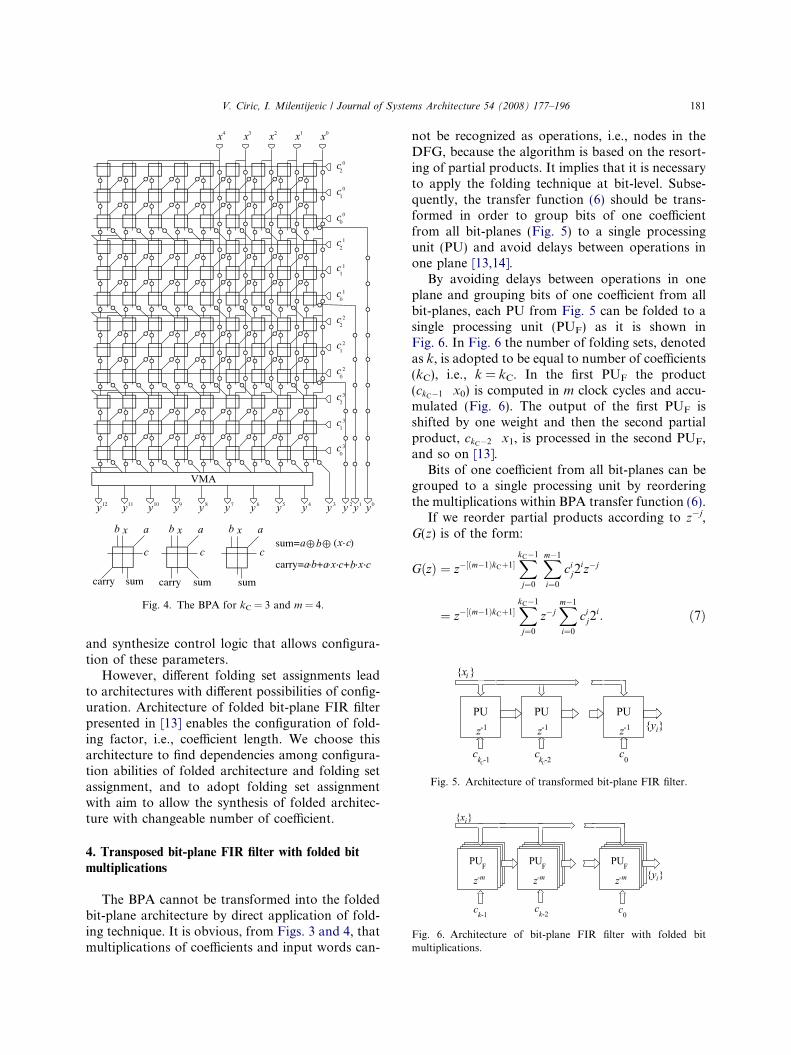
Fig. 4. The BPA for kC = 3 and m = 4.
Fig. 5. Architecture of transformed bit-plane FIR filter.
Fig. 6. Architecture of bit-plane FIR filter with folded bitmultiplications.
V. Ciric, I. Milentijevic / Journal of Systems Architecture 54 (2008) 177–196 181
and synthesize control logic that allows configura-tion of these parameters.
However, different folding set assignments leadto architectures with different possibilities of config-uration. Architecture of folded bit-plane FIR filterpresented in [13] enables the configuration of fold-ing factor, i.e., coefficient length. We choose thisarchitecture to find dependencies among configura-tion abilities of folded architecture and folding setassignment, and to adopt folding set assignmentwith aim to allow the synthesis of folded architec-ture with changeable number of coefficient.
4. Transposed bit-plane FIR filter with folded bit
multiplications
The BPA cannot be transformed into the foldedbit-plane architecture by direct application of fold-ing technique. It is obvious, from Figs. 3 and 4, thatmultiplications of coefficients and input words can-
not be recognized as operations, i.e., nodes in theDFG, because the algorithm is based on the resort-ing of partial products. It implies that it is necessaryto apply the folding technique at bit-level. Subse-quently, the transfer function (6) should be trans-formed in order to group bits of one coefficientfrom all bit-planes (Fig. 5) to a single processingunit (PU) and avoid delays between operations inone plane [13,14].
By avoiding delays between operations in oneplane and grouping bits of one coefficient from allbit-planes, each PU from Fig. 5 can be folded to asingle processing unit (PUF) as it is shown inFig. 6. In Fig. 6 the number of folding sets, denotedas k, is adopted to be equal to number of coefficients(kC), i.e., k = kC. In the first PUF the product(ckC�1 Æ x0) is computed in m clock cycles and accu-mulated (Fig. 6). The output of the first PUF isshifted by one weight and then the second partialproduct, ckC�2 Æ x1, is processed in the second PUF,and so on [13].
Bits of one coefficient from all bit-planes can begrouped to a single processing unit by reorderingthe multiplications within BPA transfer function (6).
If we reorder partial products according to z�j,G(z) is of the form:
GðzÞ ¼ z�½ðm�1ÞkCþ1�XkC�1
j¼0
Xm�1
i¼0
cij2
iz�j
¼ z�½ðm�1ÞkCþ1�XkC�1
j¼0
z�jXm�1
i¼0
cij2
i: ð7Þ
182 V. Ciric, I. Milentijevic / Journal of Systems Architecture 54 (2008) 177–196
Transformed form of transfer function (6) is
GðzÞ ¼ z0 cm�10 2m�1 þ cm�2
0 2m�2 þ � � � þ c0020
� �þ z�1 cm�1
1 2m�1 þ cm�21 2m�2 þ � � � þ c0
120� �
þ � � � þ z�ðkC�1Þ cm�1kC�12m�1 þ cm�2
kC�12m�2�
þ � � � þ c0kC�120
�: ð8Þ
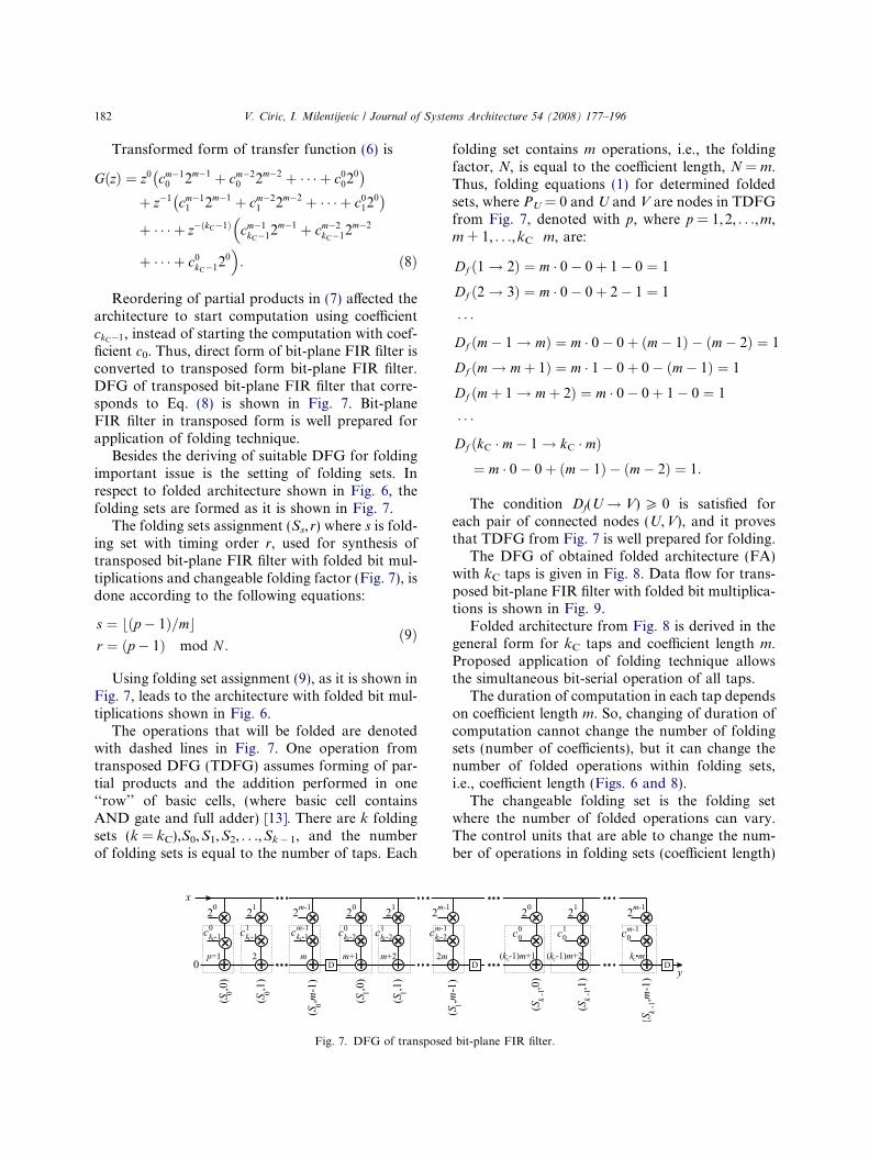
Reordering of partial products in (7) affected thearchitecture to start computation using coefficientckC�1, instead of starting the computation with coef-ficient c0. Thus, direct form of bit-plane FIR filter isconverted to transposed form bit-plane FIR filter.DFG of transposed bit-plane FIR filter that corre-sponds to Eq. (8) is shown in Fig. 7. Bit-planeFIR filter in transposed form is well prepared forapplication of folding technique.
Besides the deriving of suitable DFG for foldingimportant issue is the setting of folding sets. Inrespect to folded architecture shown in Fig. 6, thefolding sets are formed as it is shown in Fig. 7.
The folding sets assignment (Ss, r) where s is fold-ing set with timing order r, used for synthesis oftransposed bit-plane FIR filter with folded bit mul-tiplications and changeable folding factor (Fig. 7), isdone according to the following equations:
s ¼ bðp � 1Þ=mcr ¼ ðp � 1Þ mod N :
ð9Þ
Using folding set assignment (9), as it is shown inFig. 7, leads to the architecture with folded bit mul-tiplications shown in Fig. 6.
The operations that will be folded are denotedwith dashed lines in Fig. 7. One operation fromtransposed DFG (TDFG) assumes forming of par-tial products and the addition performed in one‘‘row’’ of basic cells, (where basic cell containsAND gate and full adder) [13]. There are k foldingsets (k = kC),S0,S1,S2, . . .,Sk� 1, and the numberof folding sets is equal to the number of taps. Each
Fig. 7. DFG of transposed
folding set contains m operations, i.e., the foldingfactor, N, is equal to the coefficient length, N = m.Thus, folding equations (1) for determined foldedsets, where PU = 0 and U and V are nodes in TDFGfrom Fig. 7, denoted with p, where p = 1,2, . . .,m,m + 1, . . .,kC Æ m, are:
Df ð1! 2Þ ¼ m � 0� 0þ 1� 0 ¼ 1
Df ð2! 3Þ ¼ m � 0� 0þ 2� 1 ¼ 1
� � �Df ðm� 1! mÞ ¼ m � 0� 0þ ðm� 1Þ � ðm� 2Þ ¼ 1
Df ðm! mþ 1Þ ¼ m � 1� 0þ 0� ðm� 1Þ ¼ 1
Df ðmþ 1! mþ 2Þ ¼ m � 0� 0þ 1� 0 ¼ 1
� � �Df ðkC � m� 1! kC � mÞ¼ m � 0� 0þ ðm� 1Þ � ðm� 2Þ ¼ 1:
The condition Df(U! V) P 0 is satisfied foreach pair of connected nodes (U,V), and it provesthat TDFG from Fig. 7 is well prepared for folding.
The DFG of obtained folded architecture (FA)with kC taps is given in Fig. 8. Data flow for trans-posed bit-plane FIR filter with folded bit multiplica-tions is shown in Fig. 9.
Folded architecture from Fig. 8 is derived in thegeneral form for kC taps and coefficient length m.Proposed application of folding technique allowsthe simultaneous bit-serial operation of all taps.
The duration of computation in each tap dependson coefficient length m. So, changing of duration ofcomputation cannot change the number of foldingsets (number of coefficients), but it can change thenumber of folded operations within folding sets,i.e., coefficient length (Figs. 6 and 8).
The changeable folding set is the folding setwhere the number of folded operations can vary.The control units that are able to change the num-ber of operations in folding sets (coefficient length)
bit-plane FIR filter.
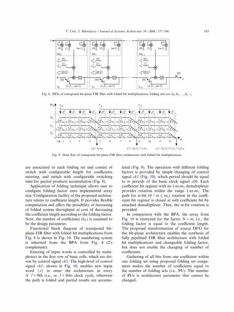
Fig. 8. DFG of transposed bit-plane FIR filter with folded bit multiplications; folding sets are S0,S1, . . .,Sk� 1.
Fig. 9. Data flow of transposed bit-plane FIR filter architecture with folded bit multiplications.
V. Ciric, I. Milentijevic / Journal of Systems Architecture 54 (2008) 177–196 183
are associated to each folding set and consist ofswitch with configurable length for coefficientsentering, and switch with configurable switchingtime for partial products accumulation (Fig. 8).
Application of folding technique allows user toconfigure folding factor onto implemented arraysize. Configuration facility of the proposed architec-ture relates to coefficient length. It provides flexiblecomputation and offers the possibility of increasingof folded system throughput at cost of decreasingthe coefficient length according to the folding factor.Now, the number of coefficients (kC) is assumed tobe the design parameter.
Functional block diagram of transposed bit-plane FIR filter with folded bit multiplications fromFig. 8 is shown in Fig. 10. The numbering systemis inherited from the BPA from Fig. 4 (2’scomplement).
Entering of input words is controlled by multi-plexers in the first row of basic cells, which are dri-ven by control signal ck1. The high-level of controlsignal ck1, shown in Fig. 10, enables new inputword {x} to enter the architecture in everyN Æ l + 0th (i.e., m Æ l + 0th) clock cycle, otherwisethe path is folded and partial results are accumu-
lated (Fig. 8). The operation with different foldingfactors is provided by simple changing of controlsignal ck1 (Fig. 10), which period should be equalto m periods of the basic clock signal ck0. Eachcoefficient bit register with its 1-to-m1 demultiplexerprovides rotation within the range 1-to-m1. Thepath for m-bit (0 < m 6 m1) rotation in the coeffi-cient bit register is closed at mth coefficient bit byattached demultiplexer. Thus, the m-bit rotation isprovided.
In comparison with the BPA, the array fromFig. 10 is restricted for the factor N = m, i.e., thefolding factor is equal to the coefficient length.The proposed transformation of source DFG forthe bit-plane architecture enables the synthesis offully pipelined FIR filter architecture with foldedbit multiplications and changeable folding factor,but does not enable the changing of number ofcoefficients.
Gathering of all bits from one coefficient withinone folding set using proposed folding set assign-ment makes the number of coefficients equal tothe number of folding sets (i.e., PU). The numberof PUs is architecture parameter that cannot bechanged.
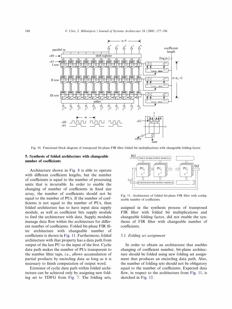
Fig. 11. Architecture of folded bit-plane FIR filter with config-urable number of coefficients.
Fig. 10. Functional block diagram of transposed bit-plane FIR filter folded bit multiplications with changeable folding factor.
184 V. Ciric, I. Milentijevic / Journal of Systems Architecture 54 (2008) 177–196
5. Synthesis of folded architecture with changeable
number of coefficients
Architecture shown in Fig. 8 is able to operatewith different coefficient lengths, but the numberof coefficients is equal to the number of processingunits that is invariable. In order to enable thechanging of number of coefficients in fixed sizearray, the number of coefficients should not beequal to the number of PUs. If the number of coef-ficients is not equal to the number of PUs, thenfolded architecture has to have input data supplymodule, as well as coefficient bits supply moduleto feed the architecture with data. Supply modulesmanage data flow within the architecture for differ-ent number of coefficients. Folded bit-plane FIR fil-ter architecture with changeable number ofcoefficients is shown in Fig. 11. Furthermore, foldedarchitecture with that property has a data path fromoutput of the last PU to the input of the first. Cyclicdata path makes the number of PUs transparent tothe number filter taps, i.e., allows accumulation ofpartial products by encircling data as long as it isnecessary to finish computation of output word.
Existence of cyclic data path within folded archi-tecture can be achieved only by assigning new fold-ing set to TDFG from Fig. 7. The folding sets,
assigned in the synthesis process of transposedFIR filter with folded bit multiplications andchangeable folding factor, did not enable the syn-thesis of FIR filter with changeable number ofcoefficients.
5.1. Folding set assignment
In order to obtain an architecture that enableschanging of coefficient number, bit-plane architec-ture should be folded using new folding set assign-ment that produces an encircling data path. Also,the number of folding sets should not be obligatoryequal to the number of coefficients. Expected dataflow, in respect to the architecture from Fig. 11, issketched in Fig. 12.
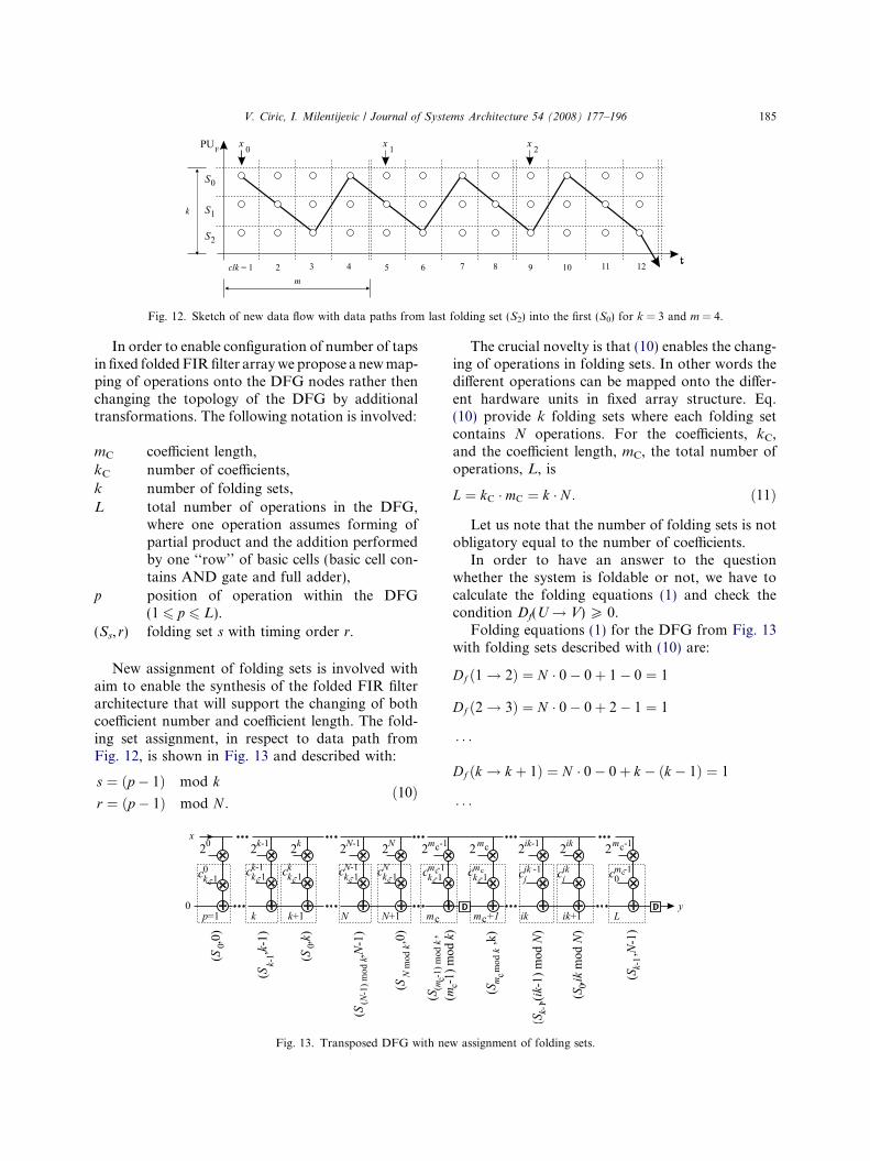
Fig. 12. Sketch of new data flow with data paths from last folding set (S2) into the first (S0) for k = 3 and m = 4.
V. Ciric, I. Milentijevic / Journal of Systems Architecture 54 (2008) 177–196 185
In order to enable configuration of number of tapsin fixed folded FIR filter array we propose a new map-ping of operations onto the DFG nodes rather thenchanging the topology of the DFG by additionaltransformations. The following notation is involved:
mC coefficient length,kC number of coefficients,k number of folding sets,L total number of operations in the DFG,
where one operation assumes forming ofpartial product and the addition performedby one ‘‘row’’ of basic cells (basic cell con-tains AND gate and full adder),
p position of operation within the DFG(1 6 p 6 L).
(Ss, r) folding set s with timing order r.
New assignment of folding sets is involved withaim to enable the synthesis of the folded FIR filterarchitecture that will support the changing of bothcoefficient number and coefficient length. The fold-ing set assignment, in respect to data path fromFig. 12, is shown in Fig. 13 and described with:
s ¼ ðp � 1Þ mod k
r ¼ ðp � 1Þ mod N :ð10Þ
Fig. 13. Transposed DFG with ne
The crucial novelty is that (10) enables the chang-ing of operations in folding sets. In other words thedifferent operations can be mapped onto the differ-ent hardware units in fixed array structure. Eq.(10) provide k folding sets where each folding setcontains N operations. For the coefficients, kC,and the coefficient length, mC, the total number ofoperations, L, is
L ¼ kC � mC ¼ k � N : ð11Þ
Let us note that the number of folding sets is notobligatory equal to the number of coefficients.
In order to have an answer to the questionwhether the system is foldable or not, we have tocalculate the folding equations (1) and check thecondition Df(U! V) P 0.
Folding equations (1) for the DFG from Fig. 13with folding sets described with (10) are:
Df ð1! 2Þ ¼ N � 0� 0þ 1� 0 ¼ 1
Df ð2! 3Þ ¼ N � 0� 0þ 2� 1 ¼ 1
� � �
Df ðk ! k þ 1Þ ¼ N � 0� 0þ k � ðk � 1Þ ¼ 1
� � �
w assignment of folding sets.
186 V. Ciric, I. Milentijevic / Journal of Systems Architecture 54 (2008) 177–196
Df ðN ! N þ 1Þ ¼ N � 0� 0þ 0� ðN � 1Þ¼ �ðN � 1Þ
� � �Df ðmC ! mC þ 1Þ ¼ N � 1� 0þ ðmC mod kÞ� ððmC � 1Þ mod kÞ¼ N þ 1
� � �Df ðn � k ! n � k þ 1Þ ¼ N � 0� 0þ ðn � k mod kÞ� ððn � k � 1Þ mod kÞ ¼ 1
� � �Df ðL� 1! LÞ ¼ N � 0� 0þ ðN � 1Þ � ðN � 2Þ ¼ 1;
ð12Þ
where PU = 0 while U and V are nodes of theTDFG denoted as p = 1,2,3, . . .,k, k + 1, . . .,N,N + 1, . . .,mC, mC + 1, . . .,n Æ k, n Æ k + 1, . . .,L � 1,L(1 6 n 6 N).
Folding equations (12) can be given in the follow-ing form:
Df ðp! p þ 1Þ¼ N � wðeÞ � 0þ ½p mod N � � ½ðp � 1Þ mod N �
¼�N þ 1; p mod N ¼ 0;
N þ 1; p mod mC ¼ 01; 1 6 p 6 L� 1;
1; other:
8><>:
ð13Þ
From (12) or (13), it can be seen that the condi-tion Df(U! V) P 0 is not satisfied for each Nthnode, i.e., for nodes U and V on positions wherepU modN = 0. The reason why the folding condi-tion is not satisfied is that there are delays betweencoefficients ci and ci + 1, i = kC � 2,kC � 1, . . ., 0, butnot between the folding sets in DFG (Fig. 13).Delays causes negative values in folding equations(12). This is the main reason for retiming of theDFG from Fig. 13.
5.2. Retiming
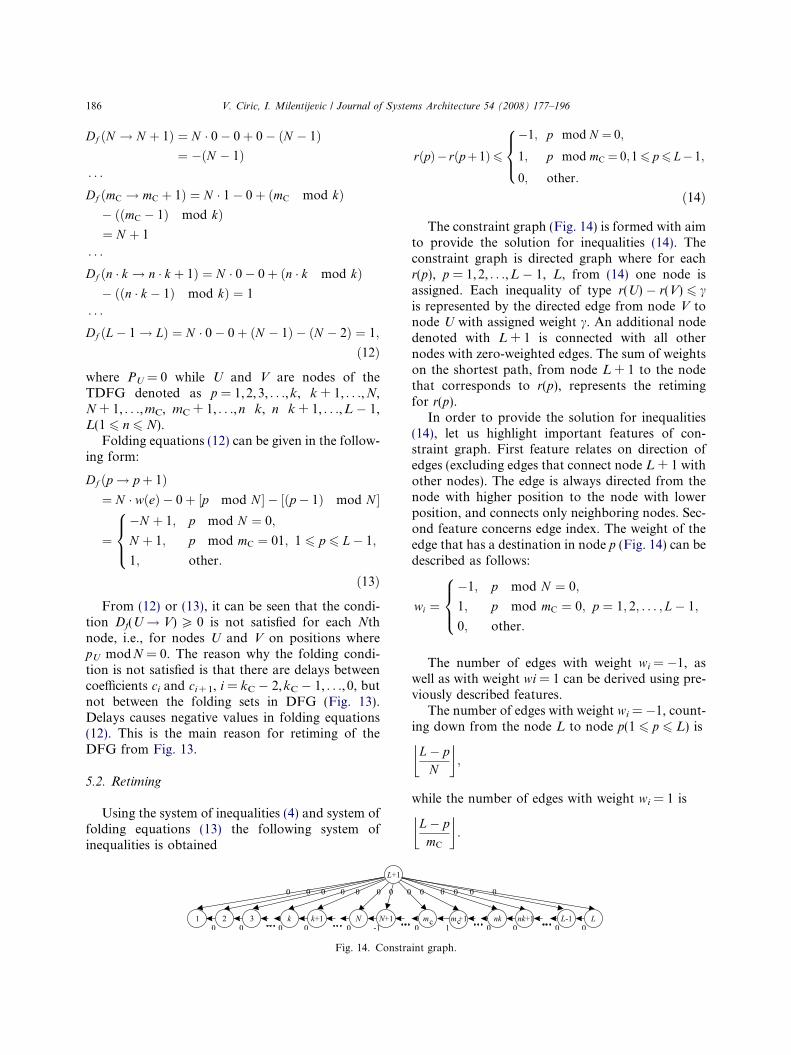
Using the system of inequalities (4) and system offolding equations (13) the following system ofinequalities is obtained
Fig. 14. Constra
rðpÞ� rðpþ 1Þ6�1; p mod N ¼ 0;
1; p mod mC ¼ 0;16 p6 L� 1;
0; other:
8><>:
ð14Þ
The constraint graph (Fig. 14) is formed with aimto provide the solution for inequalities (14). Theconstraint graph is directed graph where for eachr(p), p = 1,2, . . .,L � 1, L, from (14) one node isassigned. Each inequality of type r(U) � r(V) 6 cis represented by the directed edge from node V tonode U with assigned weight c. An additional nodedenoted with L + 1 is connected with all othernodes with zero-weighted edges. The sum of weightson the shortest path, from node L + 1 to the nodethat corresponds to r(p), represents the retimingfor r(p).
In order to provide the solution for inequalities(14), let us highlight important features of con-straint graph. First feature relates on direction ofedges (excluding edges that connect node L + 1 withother nodes). The edge is always directed from thenode with higher position to the node with lowerposition, and connects only neighboring nodes. Sec-ond feature concerns edge index. The weight of theedge that has a destination in node p (Fig. 14) can bedescribed as follows:
wi ¼�1; p mod N ¼ 0;
1; p mod mC ¼ 0; p ¼ 1; 2; . . . ; L� 1;
0; other:
8><>:
The number of edges with weight wi = �1, aswell as with weight wi = 1 can be derived using pre-viously described features.
The number of edges with weight wi = �1, count-ing down from the node L to node p(1 6 p 6 L) is
L� pN
� �;
while the number of edges with weight wi = 1 is
L� pmC
� �:
int graph.
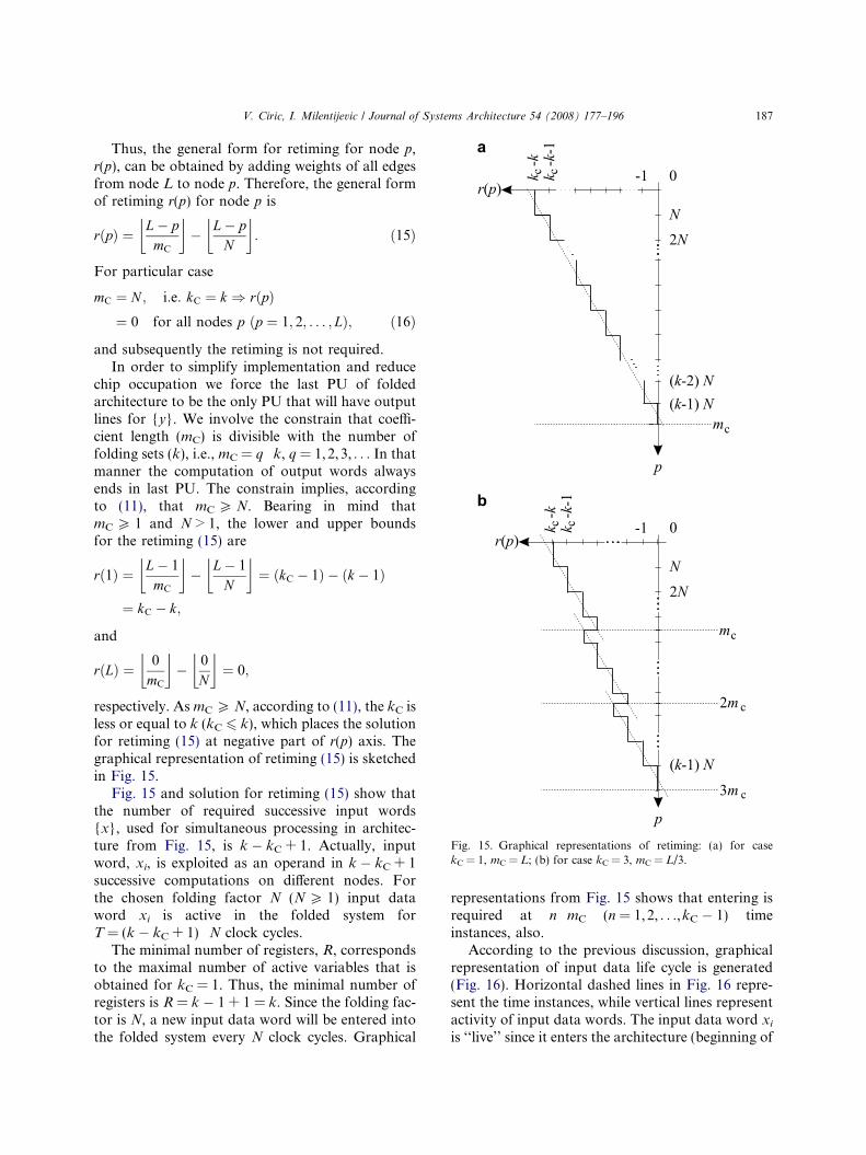
Fig. 15. Graphical representations of retiming: (a) for casekC = 1, mC = L; (b) for case kC = 3, mC = L/3.
V. Ciric, I. Milentijevic / Journal of Systems Architecture 54 (2008) 177–196 187
Thus, the general form for retiming for node p,r(p), can be obtained by adding weights of all edgesfrom node L to node p. Therefore, the general formof retiming r(p) for node p is
rðpÞ ¼ L� pmC
� �� L� p
N
� �: ð15Þ
For particular case
mC ¼ N ; i:e: kC ¼ k ) rðpÞ¼ 0 for all nodes p ðp ¼ 1; 2; . . . ; LÞ; ð16Þ
and subsequently the retiming is not required.In order to simplify implementation and reduce
chip occupation we force the last PU of foldedarchitecture to be the only PU that will have outputlines for {y}. We involve the constrain that coeffi-cient length (mC) is divisible with the number offolding sets (k), i.e., mC = q Æ k, q = 1,2,3, . . . In thatmanner the computation of output words alwaysends in last PU. The constrain implies, accordingto (11), that mC P N. Bearing in mind thatmC P 1 and N > 1, the lower and upper boundsfor the retiming (15) are
rð1Þ ¼ L� 1
mC
� �� L� 1
N
� �¼ ðkC � 1Þ � ðk � 1Þ
¼ kC � k;
and
rðLÞ ¼ 0
mC
� �� 0
N
� �¼ 0;
respectively. As mC P N, according to (11), the kC isless or equal to k (kC 6 k), which places the solutionfor retiming (15) at negative part of r(p) axis. Thegraphical representation of retiming (15) is sketchedin Fig. 15.
Fig. 15 and solution for retiming (15) show thatthe number of required successive input words{x}, used for simultaneous processing in architec-ture from Fig. 15, is k � kC + 1. Actually, inputword, xi, is exploited as an operand in k � kC + 1successive computations on different nodes. Forthe chosen folding factor N (N P 1) input dataword xi is active in the folded system forT = (k � kC + 1) Æ N clock cycles.
The minimal number of registers, R, correspondsto the maximal number of active variables that isobtained for kC = 1. Thus, the minimal number ofregisters is R = k � 1 + 1 = k. Since the folding fac-tor is N, a new input data word will be entered intothe folded system every N clock cycles. Graphical
representations from Fig. 15 shows that entering isrequired at n Æ mC (n = 1,2, . . .,kC � 1) timeinstances, also.
According to the previous discussion, graphicalrepresentation of input data life cycle is generated(Fig. 16). Horizontal dashed lines in Fig. 16 repre-sent the time instances, while vertical lines representactivity of input data words. The input data word xi
is ‘‘live’’ since it enters the architecture (beginning of
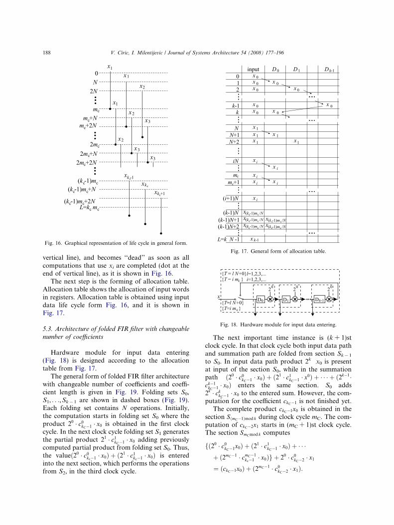
Fig. 17. General form of allocation table.
Fig. 16. Graphical representation of life cycle in general form.
Fig. 18. Hardware module for input data entering.
188 V. Ciric, I. Milentijevic / Journal of Systems Architecture 54 (2008) 177–196
vertical line), and becomes ‘‘dead’’ as soon as allcomputations that use xi are completed (dot at theend of vertical line), as it is shown in Fig. 16.
The next step is the forming of allocation table.Allocation table shows the allocation of input wordsin registers. Allocation table is obtained using inputdata life cycle form Fig. 16, and it is shown inFig. 17.
5.3. Architecture of folded FIR filter with changeable
number of coefficients
Hardware module for input data entering(Fig. 18) is designed according to the allocationtable from Fig. 17.
The general form of folded FIR filter architecturewith changeable number of coefficients and coeffi-cient length is given in Fig. 19. Folding sets S0,S1, . . .,Sk� 1 are shown in dashed boxes (Fig. 19).Each folding set contains N operations. Initially,the computation starts in folding set S0 where theproduct 20 � c0
kC�1 � x0 is obtained in the first clockcycle. In the next clock cycle folding set S1 generatesthe partial product 21 � c1
kC�1 � x0 adding previouslycomputed partial product from folding set S0. Thus,the valueð20 � c0
kc�1 � x0Þ þ ð21 � c1kc�1 � x0Þ is entered
into the next section, which performs the operationsfrom S2, in the third clock cycle.
The next important time instance is (k + 1)stclock cycle. In that clock cycle both input data pathand summation path are folded from section Sk� 1
to S0. In input data path product 2k Æ x0 is presentat input of the section S0, while in the summationpath ð20 � c0
kC�1 � x0Þ þ ð21 � c1kC�1 � x0Þ þ � � � þ ð2k�1�
ck�1kC�1 � x0Þ enters the same section. S0 adds
2k � ckkC�1 � x0 to the entered sum. However, the com-
putation for the coefficient ckC�1 is not finished yet.The complete product ckC�1x0 is obtained in the
section SðmC�1Þmod k during clock cycle mC. The com-putation of ckC�2x1 starts in (mC + 1)st clock cycle.The section SmCmod k computes
fð20 � c0kC�1x0Þ þ ð21 � c1
kC�1 � x0Þ þ � � �þ ð2mC�1 � cmC�1
kc�1 � x0Þg þ 20 � c0kC�2 � x1
¼ ðckC�1x0Þ þ ð2mC�1 � c0kC�2 � x1Þ:
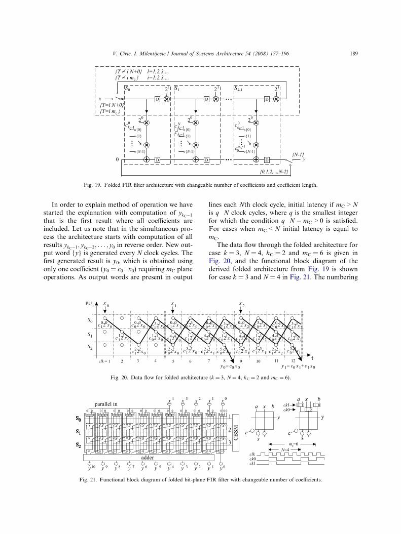
Fig. 19. Folded FIR filter architecture with changeable number of coefficients and coefficient length.
V. Ciric, I. Milentijevic / Journal of Systems Architecture 54 (2008) 177–196 189
In order to explain method of operation we havestarted the explanation with computation of ykC�1
that is the first result where all coefficients areincluded. Let us note that in the simultaneous pro-cess the architecture starts with computation of allresults ykC�1; ykC�2; . . . ; y0 in reverse order. New out-put word {y} is generated every N clock cycles. Thefirst generated result is y0, which is obtained usingonly one coefficient (y0 = c0 Æ x0) requiring mC planeoperations. As output words are present in output
Fig. 20. Data flow for folded architecture
Fig. 21. Functional block diagram of folded bit-plane F
lines each Nth clock cycle, initial latency if mC > N
is q Æ N clock cycles, where q is the smallest integerfor which the condition q Æ N � mC > 0 is satisfied.For cases when mC < N initial latency is equal tomC.
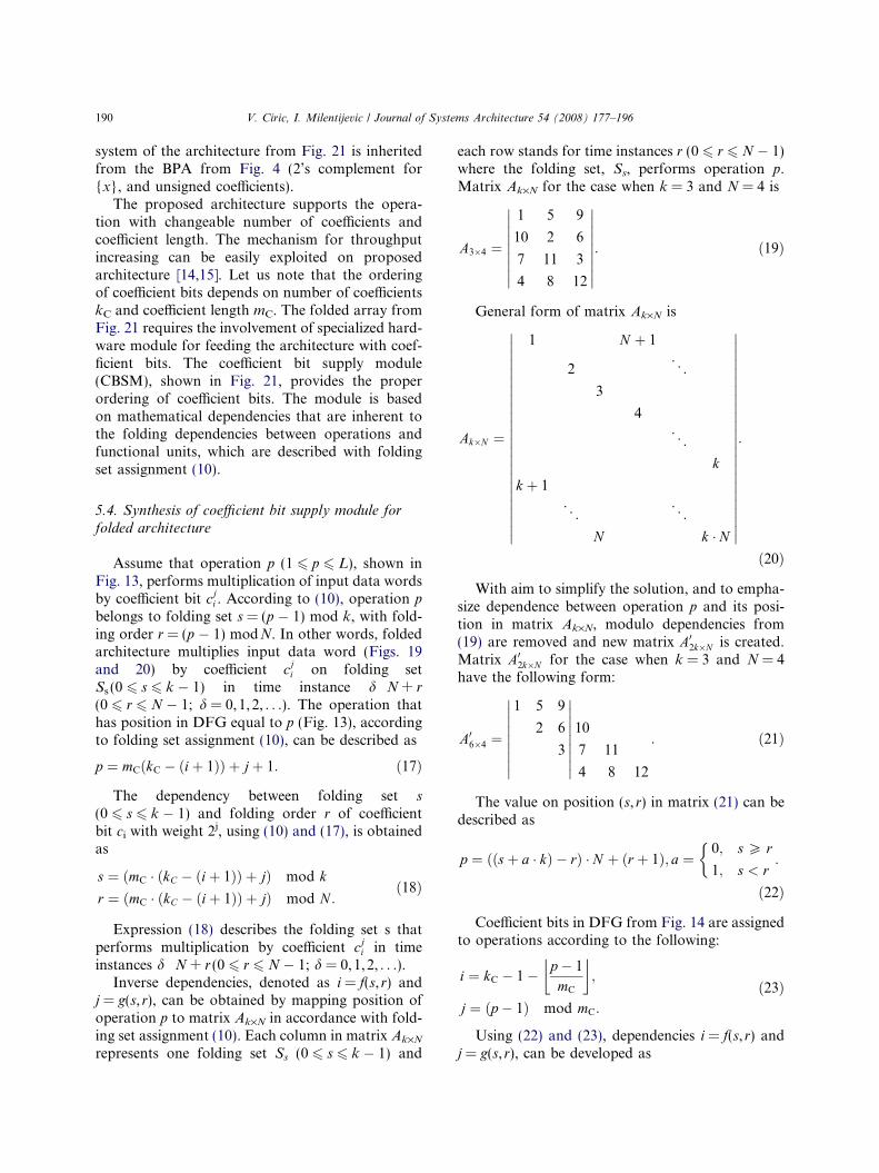
The data flow through the folded architecture forcase k = 3, N = 4, kC = 2 and mC = 6 is given inFig. 20, and the functional block diagram of thederived folded architecture from Fig. 19 is shownfor case k = 3 and N = 4 in Fig. 21. The numbering
(k = 3, N = 4, kC = 2 and mC = 6).
IR filter with changeable number of coefficients.
190 V. Ciric, I. Milentijevic / Journal of Systems Architecture 54 (2008) 177–196
system of the architecture from Fig. 21 is inheritedfrom the BPA from Fig. 4 (2’s complement for{x}, and unsigned coefficients).
The proposed architecture supports the opera-tion with changeable number of coefficients andcoefficient length. The mechanism for throughputincreasing can be easily exploited on proposedarchitecture [14,15]. Let us note that the orderingof coefficient bits depends on number of coefficientskC and coefficient length mC. The folded array fromFig. 21 requires the involvement of specialized hard-ware module for feeding the architecture with coef-ficient bits. The coefficient bit supply module(CBSM), shown in Fig. 21, provides the properordering of coefficient bits. The module is basedon mathematical dependencies that are inherent tothe folding dependencies between operations andfunctional units, which are described with foldingset assignment (10).
5.4. Synthesis of coefficient bit supply module for
folded architecture
Assume that operation p (1 6 p 6 L), shown inFig. 13, performs multiplication of input data wordsby coefficient bit cj
i . According to (10), operation p
belongs to folding set s = (p � 1) mod k, with fold-ing order r = (p � 1) modN. In other words, foldedarchitecture multiplies input data word (Figs. 19and 20) by coefficient cj
i on folding setSs (0 6 s 6 k � 1) in time instance d Æ N + r
(0 6 r 6 N � 1; d = 0,1,2, . . .). The operation thathas position in DFG equal to p (Fig. 13), accordingto folding set assignment (10), can be described as
p ¼ mCðkC � ðiþ 1ÞÞ þ jþ 1: ð17Þ
The dependency between folding set s
(0 6 s 6 k � 1) and folding order r of coefficientbit ci with weight 2j, using (10) and (17), is obtainedas
s ¼ ðmC � ðkC � ðiþ 1ÞÞ þ jÞ mod k
r ¼ ðmC � ðkC � ðiþ 1ÞÞ þ jÞ mod N :ð18Þ
Expression (18) describes the folding set s thatperforms multiplication by coefficient cj
i in timeinstances d Æ N + r (0 6 r 6 N � 1; d = 0,1,2, . . .).
Inverse dependencies, denoted as i = f(s, r) andj = g(s, r), can be obtained by mapping position ofoperation p to matrix Ak·N in accordance with fold-ing set assignment (10). Each column in matrix Ak·N
represents one folding set Ss (0 6 s 6 k � 1) and
each row stands for time instances r (0 6 r 6 N � 1)where the folding set, Ss, performs operation p.Matrix Ak·N for the case when k = 3 and N = 4 is
A3�4 ¼
1 5 9
10 2 6
7 11 3
4 8 12
���������
���������: ð19Þ
General form of matrix Ak·N is
Ak�N ¼
1 N þ 1
2 . ..
3
4
. ..
k
k þ 1
. .. . .
.
N k � N
������������������������
������������������������
:
ð20Þ
With aim to simplify the solution, and to empha-size dependence between operation p and its posi-tion in matrix Ak·N, modulo dependencies from(19) are removed and new matrix A02k�N is created.Matrix A02k�N for the case when k = 3 and N = 4have the following form:
A06�4 ¼
1 5 9
2 6
3
���������
���������10
7 11
4 8 12
: ð21Þ
The value on position (s, r) in matrix (21) can bedescribed as
p ¼ ððsþ a � kÞ � rÞ � N þ ðr þ 1Þ; a ¼0; s P r
1; s < r
:
ð22Þ
Coefficient bits in DFG from Fig. 14 are assignedto operations according to the following:
i ¼ kC � 1� p � 1
mC
� �;
j ¼ ðp � 1Þ mod mC:
ð23Þ
Using (22) and (23), dependencies i = f(s, r) andj = g(s, r), can be developed as
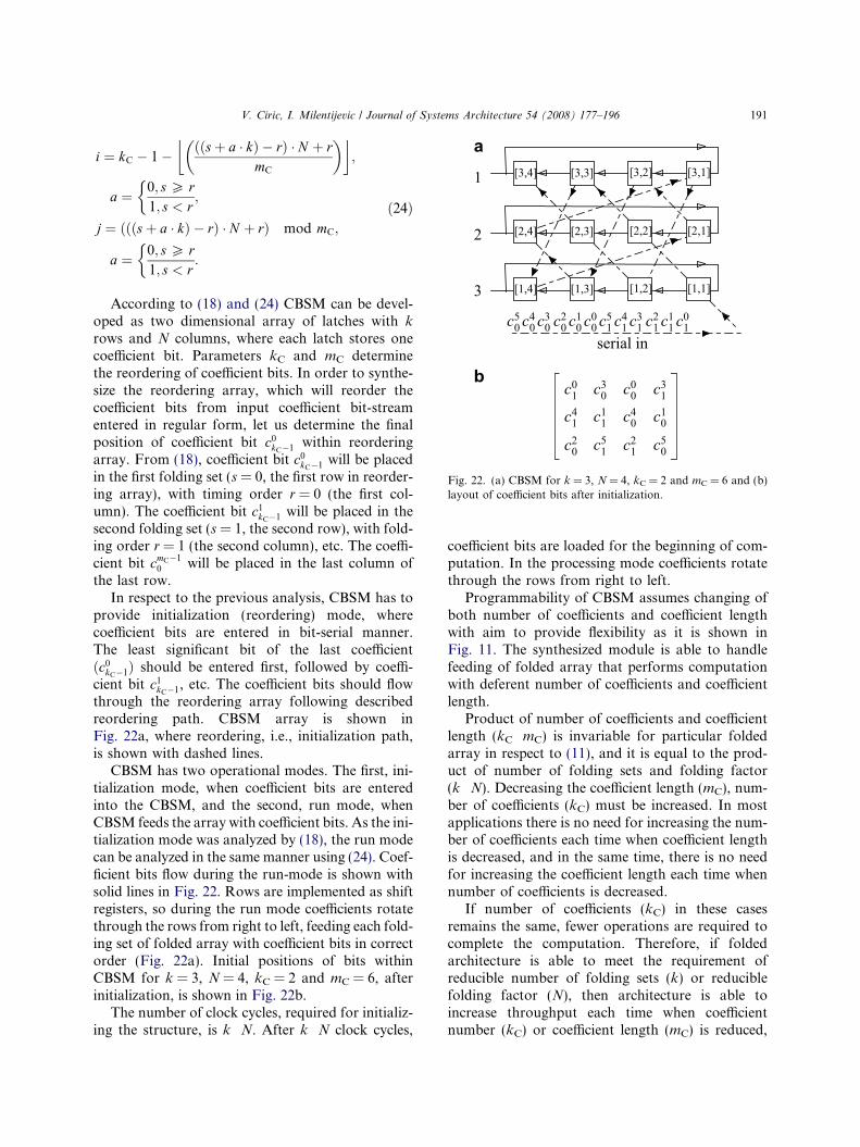
Fig. 22. (a) CBSM for k = 3, N = 4, kC = 2 and mC = 6 and (b)layout of coefficient bits after initialization.
V. Ciric, I. Milentijevic / Journal of Systems Architecture 54 (2008) 177–196 191
i ¼ kC � 1� ððsþ a � kÞ � rÞ � N þ rmC
�� �;
a ¼ 0; s P r1; s < r
;
j ¼ ðððsþ a � kÞ � rÞ � N þ rÞ mod mC;
a ¼ 0; s P r1; s < r
:
ð24Þ
According to (18) and (24) CBSM can be devel-oped as two dimensional array of latches with k
rows and N columns, where each latch stores onecoefficient bit. Parameters kC and mC determinethe reordering of coefficient bits. In order to synthe-size the reordering array, which will reorder thecoefficient bits from input coefficient bit-streamentered in regular form, let us determine the finalposition of coefficient bit c0
kC�1 within reorderingarray. From (18), coefficient bit c0
kC�1 will be placedin the first folding set (s = 0, the first row in reorder-ing array), with timing order r = 0 (the first col-umn). The coefficient bit c1
kC�1 will be placed in thesecond folding set (s = 1, the second row), with fold-ing order r = 1 (the second column), etc. The coeffi-cient bit cmC�1
0 will be placed in the last column ofthe last row.
In respect to the previous analysis, CBSM has toprovide initialization (reordering) mode, wherecoefficient bits are entered in bit-serial manner.The least significant bit of the last coefficientðc0
kC�1Þ should be entered first, followed by coeffi-cient bit c1
kC�1, etc. The coefficient bits should flowthrough the reordering array following describedreordering path. CBSM array is shown inFig. 22a, where reordering, i.e., initialization path,is shown with dashed lines.
CBSM has two operational modes. The first, ini-tialization mode, when coefficient bits are enteredinto the CBSM, and the second, run mode, whenCBSM feeds the array with coefficient bits. As the ini-tialization mode was analyzed by (18), the run modecan be analyzed in the same manner using (24). Coef-ficient bits flow during the run-mode is shown withsolid lines in Fig. 22. Rows are implemented as shiftregisters, so during the run mode coefficients rotatethrough the rows from right to left, feeding each fold-ing set of folded array with coefficient bits in correctorder (Fig. 22a). Initial positions of bits withinCBSM for k = 3, N = 4, kC = 2 and mC = 6, afterinitialization, is shown in Fig. 22b.
The number of clock cycles, required for initializ-ing the structure, is k Æ N. After k Æ N clock cycles,
coefficient bits are loaded for the beginning of com-putation. In the processing mode coefficients rotatethrough the rows from right to left.
Programmability of CBSM assumes changing ofboth number of coefficients and coefficient lengthwith aim to provide flexibility as it is shown inFig. 11. The synthesized module is able to handlefeeding of folded array that performs computationwith deferent number of coefficients and coefficientlength.
Product of number of coefficients and coefficientlength (kC Æ mC) is invariable for particular foldedarray in respect to (11), and it is equal to the prod-uct of number of folding sets and folding factor(k Æ N). Decreasing the coefficient length (mC), num-ber of coefficients (kC) must be increased. In mostapplications there is no need for increasing the num-ber of coefficients each time when coefficient lengthis decreased, and in the same time, there is no needfor increasing the coefficient length each time whennumber of coefficients is decreased.
If number of coefficients (kC) in these casesremains the same, fewer operations are required tocomplete the computation. Therefore, if foldedarchitecture is able to meet the requirement ofreducible number of folding sets (k) or reduciblefolding factor (N), then architecture is able toincrease throughput each time when coefficientnumber (kC) or coefficient length (mC) is reduced,
192 V. Ciric, I. Milentijevic / Journal of Systems Architecture 54 (2008) 177–196
in respect to equation k Æ N = kC Æ mC. The architec-ture throughput in that case could be increasedk Æ N/kC Æ mC times.
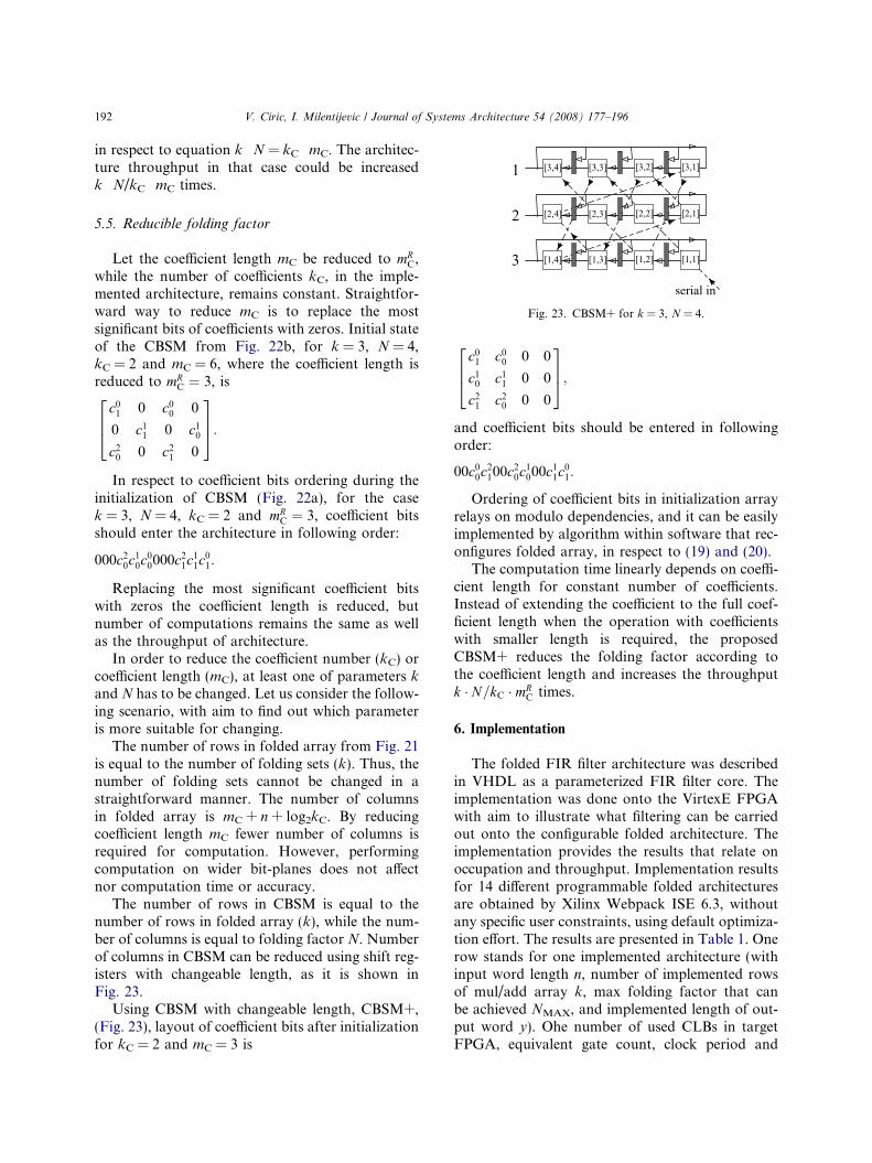
Fig. 23. CBSM+ for k = 3, N = 4.
5.5. Reducible folding factor
Let the coefficient length mC be reduced to mRC,
while the number of coefficients kC, in the imple-mented architecture, remains constant. Straightfor-ward way to reduce mC is to replace the mostsignificant bits of coefficients with zeros. Initial stateof the CBSM from Fig. 22b, for k = 3, N = 4,kC = 2 and mC = 6, where the coefficient length isreduced to mR
C ¼ 3, is
c01 0 c0
0 0
0 c11 0 c1
0
c20 0 c2
1 0
264
375:
In respect to coefficient bits ordering during theinitialization of CBSM (Fig. 22a), for the casek = 3, N = 4, kC = 2 and mR
C ¼ 3, coefficient bitsshould enter the architecture in following order:
000c20c1
0c00000c2
1c11c0
1:
Replacing the most significant coefficient bitswith zeros the coefficient length is reduced, butnumber of computations remains the same as wellas the throughput of architecture.
In order to reduce the coefficient number (kC) orcoefficient length (mC), at least one of parameters kand N has to be changed. Let us consider the follow-ing scenario, with aim to find out which parameteris more suitable for changing.
The number of rows in folded array from Fig. 21is equal to the number of folding sets (k). Thus, thenumber of folding sets cannot be changed in astraightforward manner. The number of columnsin folded array is mC + n + log2kC. By reducingcoefficient length mC fewer number of columns isrequired for computation. However, performingcomputation on wider bit-planes does not affectnor computation time or accuracy.
The number of rows in CBSM is equal to thenumber of rows in folded array (k), while the num-ber of columns is equal to folding factor N. Numberof columns in CBSM can be reduced using shift reg-isters with changeable length, as it is shown inFig. 23.
Using CBSM with changeable length, CBSM+,(Fig. 23), layout of coefficient bits after initializationfor kC = 2 and mC = 3 is
c01 c0
0 0 0
c10 c1
1 0 0
c21 c2
0 0 0
264
375;
and coefficient bits should be entered in followingorder:
00c00c2
100c20c1
000c11c0
1:
Ordering of coefficient bits in initialization arrayrelays on modulo dependencies, and it can be easilyimplemented by algorithm within software that rec-onfigures folded array, in respect to (19) and (20).
The computation time linearly depends on coeffi-cient length for constant number of coefficients.Instead of extending the coefficient to the full coef-ficient length when the operation with coefficientswith smaller length is required, the proposedCBSM+ reduces the folding factor according tothe coefficient length and increases the throughputk � N=kC � mR
C times.
6. Implementation
The folded FIR filter architecture was describedin VHDL as a parameterized FIR filter core. Theimplementation was done onto the VirtexE FPGAwith aim to illustrate what filtering can be carriedout onto the configurable folded architecture. Theimplementation provides the results that relate onoccupation and throughput. Implementation resultsfor 14 different programmable folded architecturesare obtained by Xilinx Webpack ISE 6.3, withoutany specific user constraints, using default optimiza-tion effort. The results are presented in Table 1. Onerow stands for one implemented architecture (withinput word length n, number of implemented rowsof mul/add array k, max folding factor that canbe achieved NMAX, and implemented length of out-put word y). Ohe number of used CLBs in targetFPGA, equivalent gate count, clock period and
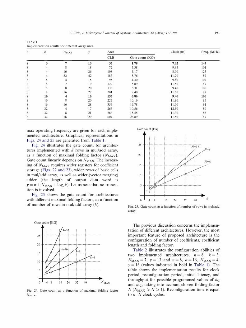
Table 1Implementation results for different array sizes
n k NMAX y Area Clock (ns) Freq. (MHz)
CLB Gate count (KG)
8 3 7 13 37 1.78 7.02 143
8 4 8 18 72 3.38 9.95 1018 4 16 26 108 5.17 8.00 1258 4 32 42 183 8.76 11.20 898 8 4 15 95 4.30 9.80 1028 8 7 19 129 5.89 11.50 878 8 8 20 136 6.31 9.40 1068 8 16 27 201 9.40 11.50 878 16 4 16 157 6.86 9.40 106
8 16 8 20 223 10.16 11.80 858 16 16 28 359 16.78 11.00 918 32 4 17 263 10.56 12.50 808 32 8 21 366 15.55 11.30 888 32 16 29 604 26.89 11.50 87
Fig. 25. Gate count as a function of number of rows in mul/add
V. Ciric, I. Milentijevic / Journal of Systems Architecture 54 (2008) 177–196 193
max operating frequency are given for each imple-mented architecture. Graphical representations inFigs. 24 and 25 are generated from Table 1.
Fig. 24 illustrates the gate count, for architec-tures implemented with k rows in mul/add array,as a function of maximal folding factor (NMAX).Gate count linearly depends on NMAX. The increas-ing of NMAX requires wider registers for coefficientstorage (Figs. 22 and 23), wider rows of basic cellsin mul/add array, as well as wider (vector merging)adder (the length of output data word isy = n + NMAX + log2 k). Let us note that no trunca-tion is involved.
Fig. 25 shows the gate count for architectureswith different maximal folding factors, as a functionof number of rows in mul/add array (k).
Fig. 24. Gate count as a function of maximal folding factorNMAX.
array.
The previous discussion concerns the implemen-tation of different architectures. However, the mostimportant feature of proposed architecture is theconfiguration of number of coefficients, coefficientlength and folding factor.
Table 2 illustrates the configuration abilities oftwo implemented architectures, n = 8, k = 3,NMAX = 7, y = 13 and n = 8, k = 16, NMAX = 4,y = 16 (values indicated in bold in Table 1). Thetable shows the implementation results for clockperiod, reconfiguration period, initial latency, andthroughput for possible programmed values of kC
and mC, taking into account chosen folding factorN (NMAX P N P 1). Reconfiguration time is equalto k Æ N clock cycles.
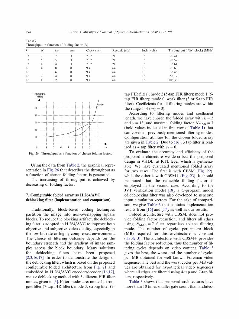
Table 2Throughput in function of folding factor (N)
k N kC mC Clock (ns) Reconf. (clk) In.lat (clk) Throughput 1/(N Æ clock) (MHz)
3 7 7 3 7.02 21 3 20.413 5 5 3 7.02 21 3 28.573 4 4 3 7.02 21 3 35.61
16 4 8 8 9.4 64 16 26.6016 3 6 8 9.4 64 18 35.4616 2 4 8 9.4 64 16 53.1916 1 2 8 9.4 64 16 106.38
Fig. 26. Throughput as a function of chosen folding factor.
194 V. Ciric, I. Milentijevic / Journal of Systems Architecture 54 (2008) 177–196
Using the data from Table 2, the graphical repre-sentation in Fig. 26 that describes the throughput asa function of chosen folding factor, is generated.
The increasing of throughput is achieved bydecreasing of folding factor.
7. Configurable folded array as H.264/AVC
deblocking filter (implementation and comparison)
Traditionally, block-based coding techniquespartition the image into non-overlapping squareblocks. To reduce the blocking artifact, the deblock-ing filter is adopted in H.264/AVC to improve bothobjective and subjective video quality, especially inthe low-bit rate or highly compressed environment.The choice of filtering outcome depends on theboundary strength and the gradient of image sam-ples across the block boundary. Many solutionsfor deblocking filters have been proposed[2,3,16,17]. In order to demonstrate the design ofthe deblocking filter, which is based on the proposedconfigurable folded architecture from Fig. 21 andembedded in H.264/AVC encoder/decoder [16,17],we use deblocking method with 5 different FIR filtermodes, given in [3]. Filter modes are: mode 4, stron-gest filter (7-tap FIR filter); mode 3, strong filter (7-
tap FIR filter); mode 2 (5-tap FIR filter); mode 1 (5-tap FIR filter); mode 0, weak filter (3 or 5-tap FIRfilter). Coefficients for all filtering modes are withinthe range 1–4 (mC = 3).
According to filtering modes and coefficientlength, we have chosen the folded array with k = 3and y = 13, and maximal folding factor NMAX = 7(bold values indicated in first row of Table 1) thatcan cover all previously mentioned filtering modes.Configuration abilities for the chosen folded arrayare given in Table 2. Due to (16), 3 tap filter is real-ized as 4 tap filter with c3 = 0.
To evaluate the accuracy and efficiency of theproposed architecture we described the proposeddesign in VHDL, at RTL level, which is synthesiz-able. We have evaluated mentioned folded arrayfor two cases. The first is with CBSM (Fig. 22),while the other is with CBSM+ (Fig. 23). It shouldbe noted that the reducible folding factor isemployed in the second case. According to theJVT verification model [18], a C-program modelof deblocking filter was also developed to generateinput simulation vectors. For the sake of compari-son, we give Table 3 that contains implementationresults from [16] and [17], as well as our results.
Folded architecture with CBSM, does not pro-vide folding factor reduction, and filters all edgesusing NMAX = 7 filter regardless to the filteringmode. The number of cycles per macro block(MB) required for this architecture is constant(Table 3). The architecture with CBSM+ providesthe folding factor reduction, thus the number of fil-tering cycles depends on video content. Table 3gives the best, the worst and the number of cyclesper MB obtained for well known Foreman videosequence. The best and the worst cycles per MB val-ues are obtained for hypothetical video sequenceswhere all edges are filtered using 4-tap and 7-tap fil-ters, respectively.
Table 3 shows that proposed architectures havemore than 10 times smaller gate count than architec-
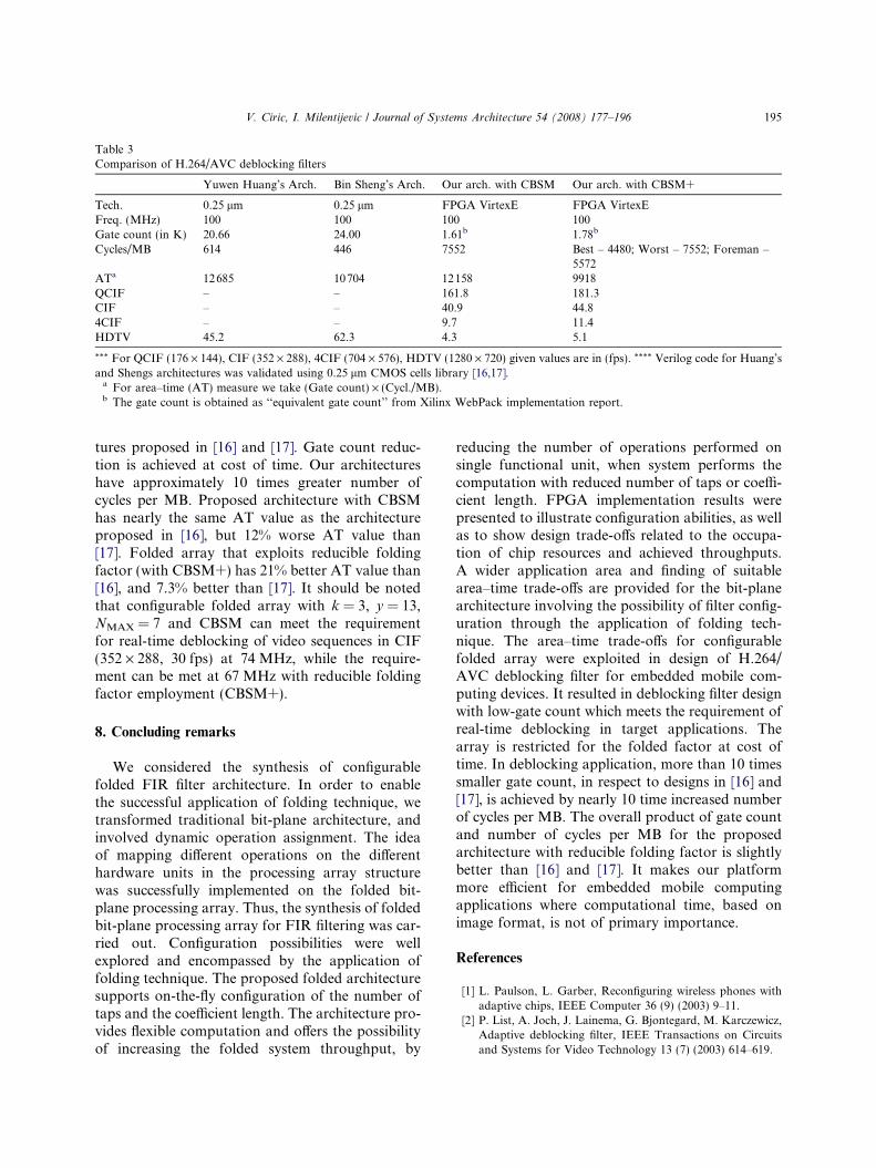
Table 3Comparison of H.264/AVC deblocking filters
Yuwen Huang’s Arch. Bin Sheng’s Arch. Our arch. with CBSM Our arch. with CBSM+
Tech. 0.25 lm 0.25 lm FPGA VirtexE FPGA VirtexEFreq. (MHz) 100 100 100 100Gate count (in K) 20.66 24.00 1.61b 1.78b
Cycles/MB 614 446 7552 Best – 4480; Worst – 7552; Foreman –5572
ATa 12685 10704 12158 9918QCIF – – 161.8 181.3CIF – – 40.9 44.84CIF – – 9.7 11.4HDTV 45.2 62.3 4.3 5.1
*** For QCIF (176 · 144), CIF (352 · 288), 4CIF (704 · 576), HDTV (1280 · 720) given values are in (fps). **** Verilog code for Huang’sand Shengs architectures was validated using 0.25 lm CMOS cells library [16,17].
a For area–time (AT) measure we take (Gate count) · (Cycl./MB).b The gate count is obtained as ‘‘equivalent gate count’’ from Xilinx WebPack implementation report.
V. Ciric, I. Milentijevic / Journal of Systems Architecture 54 (2008) 177–196 195
tures proposed in [16] and [17]. Gate count reduc-tion is achieved at cost of time. Our architectureshave approximately 10 times greater number ofcycles per MB. Proposed architecture with CBSMhas nearly the same AT value as the architectureproposed in [16], but 12% worse AT value than[17]. Folded array that exploits reducible foldingfactor (with CBSM+) has 21% better AT value than[16], and 7.3% better than [17]. It should be notedthat configurable folded array with k = 3, y = 13,NMAX = 7 and CBSM can meet the requirementfor real-time deblocking of video sequences in CIF(352 · 288, 30 fps) at 74 MHz, while the require-ment can be met at 67 MHz with reducible foldingfactor employment (CBSM+).
8. Concluding remarks
We considered the synthesis of configurablefolded FIR filter architecture. In order to enablethe successful application of folding technique, wetransformed traditional bit-plane architecture, andinvolved dynamic operation assignment. The ideaof mapping different operations on the differenthardware units in the processing array structurewas successfully implemented on the folded bit-plane processing array. Thus, the synthesis of foldedbit-plane processing array for FIR filtering was car-ried out. Configuration possibilities were wellexplored and encompassed by the application offolding technique. The proposed folded architecturesupports on-the-fly configuration of the number oftaps and the coefficient length. The architecture pro-vides flexible computation and offers the possibilityof increasing the folded system throughput, by
reducing the number of operations performed onsingle functional unit, when system performs thecomputation with reduced number of taps or coeffi-cient length. FPGA implementation results werepresented to illustrate configuration abilities, as wellas to show design trade-offs related to the occupa-tion of chip resources and achieved throughputs.A wider application area and finding of suitablearea–time trade-offs are provided for the bit-planearchitecture involving the possibility of filter config-uration through the application of folding tech-nique. The area–time trade-offs for configurablefolded array were exploited in design of H.264/AVC deblocking filter for embedded mobile com-puting devices. It resulted in deblocking filter designwith low-gate count which meets the requirement ofreal-time deblocking in target applications. Thearray is restricted for the folded factor at cost oftime. In deblocking application, more than 10 timessmaller gate count, in respect to designs in [16] and[17], is achieved by nearly 10 time increased numberof cycles per MB. The overall product of gate countand number of cycles per MB for the proposedarchitecture with reducible folding factor is slightlybetter than [16] and [17]. It makes our platformmore efficient for embedded mobile computingapplications where computational time, based onimage format, is not of primary importance.
References
[1] L. Paulson, L. Garber, Reconfiguring wireless phones withadaptive chips, IEEE Computer 36 (9) (2003) 9–11.
[2] P. List, A. Joch, J. Lainema, G. Bjontegard, M. Karczewicz,Adaptive deblocking filter, IEEE Transactions on Circuitsand Systems for Video Technology 13 (7) (2003) 614–619.
196 V. Ciric, I. Milentijevic / Journal of Systems Architecture 54 (2008) 177–196
[3] Z. Yu, J. Zhang, Video deblocking with fine-grained scalablecomplexity for embedded mobile computing, InternationalConference on Signal Processing 2 (September) (2004) 1173–1178.
[4] I. Richardson, H.264 and MPEG-4 Video Compression –Video Coding for Next Generation Multimedia, John Wileyand Sons, Inc., New York, 2003.
[5] D. Reuver, H. Klar, A configurable convolution chip withprogrammable coefficients, IEEE Journal of Solid StateCircuits 27 (7) (1992) 1121–1123.
[6] Y.-C. Lin, F.-C. Lin, Classes of systolic arrays for digitalfiltering, International Journal of Electronics 70 (4) (1991)729–737.
[7] I. Milentijevic, M.S. Stojcev, D. Maksimovic, Configurabledigit – Serial convolver of type F, Microelectronics Journal27 (6) (1996) 559–566.
[8] P. Corsonello, S. Perri, G. Cocorullo, Area–time–powertradeoff in cellular arrays VLSI implementations, IEEETransaction on Very Large Scale Integration (VLSI) Systems8 (5) (2000) 614–624.
[9] R. Lin, Reconfigurable parallel inner product processorarchitectures, IEEE Transactions on VLSI Systems 9 (2)(2001) 261–272.
[10] Robert Hawley, Bennett Wong, Thu-ji Lin, Joe Laskowski,Henry Samueli, Design techniques for silicon compilerimplementations of high-speed FIR digital filters, IEEEJournal of Solid-State Circuits 31 (5) (1996).
[11] K.K. Parhi, VLSI Digital Signal Processing Systems (Designand Implementation), John Wiley and Sons, Inc., New York,2000.
[12] T. Noll, Semi-systolic Maximum Rate Transversal Filterswith Programmable coefficients, in: Proceedings of Work-shop on Systolic Architectures, Oxford, 1986, pp. 103–112.
[13] I. Milentijevic, V. Ciric, O. Vojinovic, T. Tokic, FoldedSemi-Systolic FIR Filter Architecture with ChangeableFolding Factor, Neural, Parallel and Scientific Computa-tions 10 (2) (2002) 235–247.
[14] I. Milentijevic, V. Ciric, T. Tokic and O. Vojinovic, FPGAImplementation of Folded FIR Filter Architecture withChangeable Folding Factor, Facta Universitatis, Ser. Elec-tronics and Energetics 15(3), pp. 451–464. University of Nis,Yugoslavia.
[15] I.Z. Milentijevic, V. Ciric, T. Tokic and O. Vojinovic, FoldedBit-Plane FIR Filter Architecture with Changeable Folding
Factor, DSD 2002, in: Proceedings of EUROMICRO –Digital System Design, Dortmund, Germany, September2002, pp. 45–52.
[16] Y. Huang, T. Chen, Architecture Design for DeblockingFilter in H.264/AVC, in: Proceedings of ICME, Baltimore,Maryland, USA, July 2003, pp. 692–696.
[17] B. Sheng, W. Gao, D. Wu, An Implemented Architecture ofDeblocking Filter for H.264/AVC, in: Proceedings of Inter-national Conference on Image Processing (ICIP), 2004, pp.665–668.
[18] JVT software JM10.2, January 2006.
Vladimir M. Ciric is a teaching andresearch assistant in the Faculty ofElectronic Engineering at the Universityof Nis, Serbia. Both B.S. and M.Sc.degrees he received from Faculty ofElectronic Engineering, University ofNis 2001 and 2005, respectively, wherehe currently attends the Ph.D. studies.His research interests include computerarchitectures, fast arithmetic, digitalimage processing and video coding.
Ivan Z. Milentijevic is an AssociatedProfessor at Faculty of Electronic Engi-neering, University of Nis, Serbia. Hereceived B.S. in Electrical engineeringand M.Sc. and Ph.D. degree in Com-puter Science from the Faculty of Elec-tronic Engineering in 1989, 1994 and1998, respectively. His research interestsinclude computer architecture, parallelprocessing, fast and fault tolerant arith-metic, digital signal processing and
computer science education. He has published 15 journal papersand coordinated and managed 2 international projects. Currently
he is the head of Computer Science Department at University ofNis.


![MPC8548E Configurable Development System … Configurable Development System Reference Manual, ... [4:0] ... MPC8548E Configurable Development System Reference Manual,](https://img.pdfslide.net/doc/110x75/5af028337f8b9ac62b8e4c0e/mpc8548e-configurable-development-system-configurable-development-system-reference.jpg)