Embed Size (px)
Citation preview

Configuration Instruction IPS Analytics Applications

Copyright 2017 Securiton GmbH.
IPS and the IPS logo are registered trademarks of Securiton GmbH.
Securiton GmbH has included the information contained in this manual to the best of its knowledge. Con-tent of this documentation exclusively serves information purposes and may be changed without prior notice. Securiton GmbH accepts no responsibility for damage or accidents, which occur as a conse-quence of information, which has been given regarding devices or components not manufactured by it-self. Securiton GmbH accepts no responsibility for changes or modifications, which have not been explic-itly authorised by Securiton GmbH.
Document Revision: 17/03/17 | R01 Securiton GmbH IPS Intelligent Video Analytics Kronstadter Str. 4 D-81677 München Tel. +49 89 451590-0 Fax +49 89 451590-88 [email protected] www.ips-analytics.com

3 / 27 | 17/03/17 | V8.0 R01 A Business Unit of Securiton GmbH IPS
Configuration Instruction
IPS Analytics Applications for Axis ACAP Cameras and Encoders
Contents
1 Analytics Configuration ....................................................................................................................... 6
2 Overview of Functions and Areas ...................................................................................................... 7
3 Editing the Analytics Configuration ................................................................................................... 8
4 Backup and Restore of an Analytics Configuration ......................................................................... 8
5 Editing the Analytics Global Parameters ........................................................................................... 8
6 IPS Intrusion Detection ........................................................................................................................ 9
6.1 Selecting an Application .................................................................................................................. 9 6.2 Configuring an Open Area Application............................................................................................ 9
6.2.1 Selecting the Application ......................................................................................................... 9 6.2.2 Specifying the Detection Direction ........................................................................................... 9 6.2.3 Adapting the Object Sizes ....................................................................................................... 9 6.2.4 Drawing the Virtual Boundary .................................................................................................. 9 6.2.5 Result of the Graphical Configuration and Expert Steps ......................................................... 9 6.2.6 Adapting the Zones ................................................................................................................ 10 6.2.7 Changing the Minimum Distance ........................................................................................... 10 6.2.8 Editing the Analytic Parameters ............................................................................................. 10 6.2.9 Saving the Profile ................................................................................................................... 11
6.3 Configuring an Entrance Application............................................................................................. 11 6.3.1 Selecting the Application ....................................................................................................... 11 6.3.2 Adapting the Object Sizes ..................................................................................................... 11 6.3.3 Adjusting the Façade Marking ............................................................................................... 11 6.3.4 Marking the Door Frame ........................................................................................................ 11 6.3.5 Result of the Graphical Configuration and Expert Steps ....................................................... 11 6.3.6 Adapting the Zones ................................................................................................................ 12 6.3.7 Changing the Minimum Distance ........................................................................................... 12 6.3.8 Editing the Analytic Parameters ............................................................................................. 12 6.3.9 Saving the Profile ................................................................................................................... 13
6.4 Configuring a Building Application ................................................................................................ 13 6.4.1 Selecting the Application ....................................................................................................... 13 6.4.2 Adapting the Object Sizes ..................................................................................................... 13 6.4.3 Adjusting the Façade Marking ............................................................................................... 13 6.4.4 Setting the Detection Direction .............................................................................................. 13 6.4.5 Result of the Graphical Configuration and Expert Steps ....................................................... 13 6.4.6 Adapting the Zones ................................................................................................................ 14 6.4.7 Changing the Minimum Distance ........................................................................................... 14 6.4.8 Editing the Analytic Parameters ............................................................................................. 14 6.4.9 Saving the Profile ................................................................................................................... 15
6.5 Configuring a Fence Application ................................................................................................... 15 6.5.1 Selecting the Application ....................................................................................................... 15 6.5.2 Adapting the Object Sizes ..................................................................................................... 15

4 / 27 | 17/03/17 | V8.0 R01 A Business Unit of Securiton GmbH IPS
6.5.3 Adjusting Perimeter Marking .................................................................................................. 15 6.5.4 Setting the Detection Direction .............................................................................................. 15 6.5.5 Result of the Graphical Configuration and Expert Steps ....................................................... 16 6.5.6 Adapting the Zones ................................................................................................................ 16 6.5.7 Changing the Minimum Distance ........................................................................................... 16 6.5.8 Editing the Analytic Parameters ............................................................................................. 16 6.5.9 Saving the Profile ................................................................................................................... 17
6.6 Intrusion Detection Global Parameters ......................................................................................... 17 6.6.1 Snowfall ................................................................................................................................. 17 6.6.2 Camera identification ............................................................................................................. 17 6.6.3 Initial state at startup .............................................................................................................. 17 6.6.4 Automatic acknowledgement ................................................................................................. 17 6.6.5 Connection to video management system ............................................................................ 17 6.6.6 Day or night mode ................................................................................................................. 18
7 IPS Indoor Detection .......................................................................................................................... 18
7.1 Indoor Detection Application Configuration .................................................................................. 18 7.1.1 Adapting the Object Sizes ..................................................................................................... 18 7.1.2 Adapting the Alarm Zone ....................................................................................................... 18 7.1.3 Adapting the Result of the Graphical Configuration .............................................................. 18 7.1.4 Editing the Analytic Parameters ............................................................................................. 19 7.1.5 Saving the Profile ................................................................................................................... 19
7.2 Indoor Detection Global Parameters............................................................................................. 19 7.2.1 Camera identification ............................................................................................................. 19 7.2.2 Initial state at startup .............................................................................................................. 19 7.2.3 Automatic acknowledgement ................................................................................................. 19 7.2.4 Connection to video management system ............................................................................ 19 7.2.5 Day or night mode ................................................................................................................. 20
8 IPS Motion Detection ......................................................................................................................... 20
8.1 Motion Detection Application Configuration .................................................................................. 20 8.1.1 Adapting the Object Sizes ..................................................................................................... 20 8.1.2 Adapting the Detection Zone ................................................................................................. 20 8.1.3 Adapting the Result of the Graphical Configuration .............................................................. 20 8.1.4 Editing the Analytic Parameters ............................................................................................. 21 8.1.5 Saving the Profile ................................................................................................................... 21
8.2 Motion Detection Global Parameters ............................................................................................ 21 8.2.1 Camera identification ............................................................................................................. 21 8.2.2 Initial state at startup .............................................................................................................. 21 8.2.3 Automatic acknowledgement ................................................................................................. 21 8.2.4 Connection to video management system ............................................................................ 21 8.2.5 Day or night mode ................................................................................................................. 22
9 IPS Sabotage Detection ..................................................................................................................... 23
9.1 Sabotage Detection Application Configuration ............................................................................. 23 9.1.1 Adapting the Sabotage Zone ................................................................................................. 23 9.1.2 Editing the Analytic Parameters ............................................................................................. 23 9.1.3 Saving the Profile ................................................................................................................... 23
9.2 Sabotage Detection Global Parameters ....................................................................................... 23 9.2.1 Camera identification ............................................................................................................. 24

5 / 27 | 17/03/17 | V8.0 R01 A Business Unit of Securiton GmbH IPS
9.2.2 Initial state at startup .............................................................................................................. 24 9.2.3 Automatic acknowledgement ................................................................................................. 24 9.2.4 Connection to video management system ............................................................................ 24 9.2.5 Day or night mode ................................................................................................................. 24
10 IPS Loitering Detection ...................................................................................................................... 25
10.1 Loitering Detection Application Configuration ............................................................................... 25 10.1.1 Adapting the Object Sizes ..................................................................................................... 25 10.1.2 Adapting the Loitering Zone ................................................................................................... 25 10.1.3 Adapting the Result of the Graphical Configuration .............................................................. 25 10.1.4 Editing the Analytic Parameters ............................................................................................. 25 10.1.5 Saving the Profile ................................................................................................................... 26
10.2 Loitering Detection Global Parameters ......................................................................................... 26 10.2.1 Camera identification ............................................................................................................. 26 10.2.2 Initial state at startup .............................................................................................................. 26 10.2.3 Automatic acknowledgement ................................................................................................. 26 10.2.4 Connection to video management system ............................................................................ 26 10.2.5 Day or night mode ................................................................................................................. 27
6 / 27 | 17/03/17 | V8.0 R01 A Business Unit of Securiton GmbH IPS
1 Analytics Configuration
To open the IPS WebConfigurator proceed as follows:
1. Open the camera’s web site. You are provided with the start page shown below.
2. Make sure you have read the Licence agreement and activated the confirmation check box.
3. Click on the button IPS WebConfigurator.
7 / 27 | 17/03/17 | V8.0 R01 A Business Unit of Securiton GmbH IPS
2 Overview of Functions and Areas
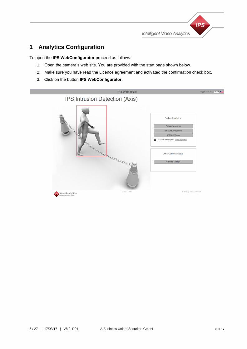
The IPS WebConfigurator is designed as a wizard. It guides you through the different steps of the con-figuration. Proceed from step to step clicking on the Next button. If you want to make a change in any of the previous steps click on the Back button.
The camera image is displayed in the working area, where all the graphical configuration is done.
Help text is displayed in the lower left window.
Help drawings in the lower right window illustrate the different steps.
You may want to surveil different areas in different situations (for example during the day and at night). For this purpose you can use different profiles. To configure another profile, select it and perform all the configuration steps.
To rename a profile click on the Rename profile button.
To reset a profile to the default values click on the Reset profile to default button.
Under Configuration Workflow the current state is displayed. Steps you have successfully passed through are marked by a green circle.
Working area
Help text Help drawings
Profiles section Configuration workflow

8 / 27 | 17/03/17 | V8.0 R01 A Business Unit of Securiton GmbH IPS
3 Editing the Analytics Configuration
To change the configuration of an IPS Analytics application proceed as follows:
1. Open the IPS WebConfigurator.
2. Select the profile you want to change.
3. Click on Next until you have reached the step where you want to make a change.
4. Click on Next until the Save button appears.
5. Click on Save.
6. Select an option from the following choices:
Select next profile
Open viewer
Go to beginning
4 Backup and Restore of an Analytics Configuration
At the last step of an Analytics configuration you can save a copy of the settings on the hard disk of your PC. When you click on Backup, a file with the settings is stored to the download directory. The name of the file is generated automatically. It is structured as follows: ips-analytics-config_<IP address>.
At the first step of an Analytics configuration you can load previously saved settings by clicking on Re-store. The WebConfigurator then opens a dialog, in which you can select the settings file. Click on Open to load the file.
5 Editing the Analytics Global Parameters
This section describes only the general proceeding. For details on the parameters refer to the global pa-rameters section of the Analytics application.
To edit the Global Parameters proceed as follows:
1. Open the camera’s web site. You are provided with the start page.
2. Click on the button Global Parameters.
When you have made all the changes to the Global Parameters click on the Next button.
Click on the Save button to save the changes or on Back to further adapt the Global Parameters.
After having clicked on Save you may select an option from the following choices:
Open viewer
Go to beginning (start page)
9 / 27 | 17/03/17 | V8.0 R01 A Business Unit of Securiton GmbH IPS
6 IPS Intrusion Detection
6.1 Selecting an Application
For the IPS Intrusion Detection first choose an application.
You may select from Open area, Entrance, Building, or Fence.
For an Entrance, Building, or Fence application select the camera position.
The wizard then guides you through the different configuration steps.
A drawing left to the camera image illustrates the application or the camera position.
6.2 Configuring an Open Area Application
6.2.1 Selecting the Application
After having started the IPS WebConfigurator select Open area and click Next.
6.2.2 Specifying the Detection Direction
Select one of the following options:
Motion from left to right
Motion from right to left
Motion from both directions
Motion in any direction
Depending on your selection, the zones automatically created in a later step will differ.
6.2.3 Adapting the Object Sizes
At two different points in the image the object size (size of a person) must be specified; one of them must be in the foreground and one in the background.
To adapt the object sizes proceed as follows:
1. Position a person in the foreground of the image.
2. Click within the blue object size rectangle and drag it over the person.
3. To adjust the object size click on one of the corner points and move it. Adapt it so that the rectangle matches the size of the person as precisely as possible.
4. Perform the same for the object size in the background (green rectangle).
5. Click on Next.
6.2.4 Drawing the Virtual Boundary
The virtual boundary is a line an intruder must cross in order to trigger an alarm. You can adapt the predefined virtual boundary by moving (clicking and dragging) the end points of the line. Click on Next when you are finished.
6.2.5 Result of the Graphical Configuration and Expert Steps
In this step the result of the graphical configuration is displayed. If you want to adapt the zones or change the minimum distance click on Expert steps.

10 / 27 | 17/03/17 | V8.0 R01 A Business Unit of Securiton GmbH IPS
6.2.6 Adapting the Zones
For the detection directions Motion from left to right, Motion from right to left, and Motion from both direc-tions Intrusion Detection provides a capture zone (green), an alarm zone (yellow). For these cases an alarm is triggered only when an object moves from the capture zone to the alarm zone and if the object has covered the minimum distance in one of the specified directions (see also next section).
When detecting Motion in any direction Intrusion Detection provides a capture zone (green) and a priority zone (red). In this case an alarm is triggered if an object enters the priority zone and if the object has cov-ered the minimum distance in one of the specified directions (see also next section). Using a capture zone helps to trigger the alarm earlier as the distance starts counting already in the capture zone.
To adapt the zones you can use the following functions:
moving corners of the polygons or the polygons themselves when the drawing tool is se-lected,
adding points to the polygons when the adding tool is selected, or
deleting points from the polygons when the deleting tool is selected.
When you are finished click on Next.
6.2.7 Changing the Minimum Distance
The minimum distances specify the distance an object must cover in a certain direction for an alarm to be triggered.
If you want to change the distance move the mouse pointer over the arrowhead and click and drag.
A grey arrow indicates that a movement in the corresponding direction does not trigger an alarm. If you extend a grey arrow its colour changes to red and the corresponding direction is activated.
To see how the distance is adapted according to the perspective (defined by the object sizes in the fore-ground and in the background), move the mouse pointer inside the small circle in the middle of the vector cross and click and drag it around in the image.
6.2.8 Editing the Analytic Parameters
IPS Intrusion Detection in fact is a package consisting of three different functions: Besides the intrusion detection it also can trigger events in the case of an activity or in the case the cam-era is being tampered with.
The parameters refer to these functions.
Activity switch-off delay: After an activity is finished the activity event is still active until the activity switch-off delay has elapsed. When both are finished the activity recording also ends.
Two cases of tampering are detected: low contrast for example in the case the lens is covered and change of the camera position. The whole image is used for this purpose.
Video alarm in case of low contrast: You may enable or disable a tampering alarm caused by low con-trast.
Video alarm in case of camera position checking: You may enable or disable a tampering alarm caused by change of the camera position.
Filter for recognizing headlights: Activate this filter only if the camera chip is ARTPEC-4 or higher. For the chip type refer to the compatibility list.
Highly sensitive detection: Enable this feature if in some cases no alarm is triggered. Before enabling this feature make sure you have correctly adapted the object sizes.
Adapt the parameters as required and click on Next.
11 / 27 | 17/03/17 | V8.0 R01 A Business Unit of Securiton GmbH IPS
6.2.9 Saving the Profile
Click on Save to store the configuration to the camera or click on Back to further adapt the configuration.
After having clicked on Save you may select an option from the following choices:
Select next profile
Open viewer
Go to beginning
6.3 Configuring an Entrance Application
6.3.1 Selecting the Application
After having started the IPS WebConfigurator select Entrance. Click on Next. Then select the camera position: Camera on the left or Camera on the right. Click on Next. Note: The entrance should be clearly visible in the image, but the camera should not look to the entrance at a right angle.
6.3.2 Adapting the Object Sizes
At two different points in the image the object size (size of a person) must be specified; one of them must be in the foreground and one in the background.
To adapt the object sizes proceed as follows:
1. Position a person in the foreground of the image close to the building.
2. Click within the blue object size rectangle and drag it over the person.
3. To adjust the object size click on one of the corner points and move it. Adapt it so that the rectangle matches the size of the person as precisely as possible.
4. Perform the same for the object size in the background (green rectangle).
5. Click on Next.
6.3.3 Adjusting the Façade Marking
The IPS WebConfigurator automatically calculates the size and position of the building façade. It displays the result in the form of the facade marking. If necessary adjust the corners maintaining their original function (e.g. base point in the front remains base point in the front). Note: The marking should at least incorporate the top of the door frame.
Click on Next.
6.3.4 Marking the Door Frame
The entrance must be marked by a rectangle. Adjust the default rectangle displayed in this step to the size and the position of the entrance. To achieve this, move the rectangle to the position of the entrance and adapt the corners so that it surrounds the door frame.
Click on Next.
6.3.5 Result of the Graphical Configuration and Expert Steps
In this step the result of the graphical configuration is displayed. If you want to adapt the zones or change the minimum distance click on Expert steps.

12 / 27 | 17/03/17 | V8.0 R01 A Business Unit of Securiton GmbH IPS
6.3.6 Adapting the Zones
Intrusion Detection provides a capture zone (green) and an alarm zone (yellow). An alarm is triggered only when an object moves from the capture zone (green) to the alarm zone (yellow, marking of the door frame).
To adapt the zones you can use the following functions:
moving corners of the polygons or the polygons themselves when the drawing tool is se-lected,
adding points to the polygons when the adding tool is selected, or
deleting points from the polygons when the deleting tool is selected.
Important note: Be sure to maintain the yellow zone (marking of the door frame) inside the green zone (capture zone).
When you are finished click on Next.
6.3.7 Changing the Minimum Distance
The minimum distances specify the distance an object must cover in a certain direction for an alarm to be triggered .
If you want to change the distance move the mouse pointer over the arrowhead and click and drag.
A grey arrow indicates that a movement in the corresponding direction does not trigger an alarm. If you extend a grey arrow its colour changes to red and the corresponding direction is activated.
To see how the distance is adapted according to the perspective (defined by the object sizes in the fore-ground and in the background), move the mouse pointer inside the small circle in the middle of the vector cross and click and drag it around in the image.
6.3.8 Editing the Analytic Parameters
IPS Intrusion Detection in fact is a package consisting of three different functions: Besides the intrusion detection it also can trigger events in the case of an activity or in the case the cam-era is being tampered with.
The parameters refer to these functions.
Activity switch-off delay: After an activity is finished the activity event is still active until the activity switch-off delay has elapsed. When both are finished the activity recording also ends.
Two cases of tampering are detected: low contrast for example in the case the lens is covered and change of the camera position. The whole image is used for this purpose.
Video alarm in case of low contrast: You may enable or disable a tampering alarm caused by low con-trast.
Video alarm in case of camera position checking: You may enable or disable a tampering alarm caused by change of the camera position.
Filter for recognizing headlights: Activate this filter only if the camera chip is ARTPEC-4 or higher. For the chip type refer to the compatibility list.
Highly sensitive detection: Enable this feature if in some cases no alarm is triggered. Before enabling this feature make sure you have correctly adapted the object sizes.
Adapt the parameters as required and click on Next.

13 / 27 | 17/03/17 | V8.0 R01 A Business Unit of Securiton GmbH IPS
6.3.9 Saving the Profile
Click on Save to store the configuration to the camera or click on Back to further adapt the configuration.
After having clicked on Save you may select an option from the following choices:
Select next profile
Open viewer
Go to beginning
6.4 Configuring a Building Application
6.4.1 Selecting the Application
After having started the IPS WebConfigurator select Building. Click on Next. Then select the camera position: Camera on the left or Camera on the right. Click on Next.
6.4.2 Adapting the Object Sizes
At two different points in the image the object size (size of a person) must be specified; one of them must be in the foreground and one in the background.
To adapt the object sizes proceed as follows:
1. Position a person in the foreground of the image close to the building.
2. Click within the blue object size rectangle and drag it over the person.
3. To adjust the object size click on one of the corner points and move it. Adapt it so that the rectangle matches the size of the person as precisely as possible.
4. Perform the same for the object size in the background (green rectangle).
5. Click on Next.
6.4.3 Adjusting the Façade Marking
The IPS WebConfigurator automatically calculates the size and position of the building façade. It displays the result in the form of the facade marking. If necessary adjust the corners maintaining their original function (e.g. base point in the front remains base point in the front).
Click on Next.
6.4.4 Setting the Detection Direction
Click anywhere in the image to change the direction from left to right or vice versa.
Click on Next.
6.4.5 Result of the Graphical Configuration and Expert Steps
In this step the result of the graphical configuration is displayed. If you want to adapt the zones or change the minimum distance click on Expert steps.
14 / 27 | 17/03/17 | V8.0 R01 A Business Unit of Securiton GmbH IPS
6.4.6 Adapting the Zones
Intrusion Detection provides a capture zone (green) and an alarm zone (yellow). An alarm is triggered only when an object moves from the capture zone (green) to the alarm zone (yellow).
To adapt the zones you can use the following functions:
moving corners of the polygons or the polygons themselves when the drawing tool is se-lected,
adding points to the polygons when the adding tool is selected, or
deleting points from the polygons when the deleting tool is selected.
Important note: Be sure to maintain the zone overlap.
When you are finished click on Next.
6.4.7 Changing the Minimum Distance
The minimum distances specify the distance an object must cover in a certain direction for an alarm to be triggered .
If you want to change the distance move the mouse pointer over the arrowhead and click and drag.
A grey arrow indicates that a movement in the corresponding direction does not trigger an alarm. If you extend a grey arrow its colour changes to red and the corresponding direction is activated.
To see how the distance is adapted according to the perspective (defined by the object sizes in the fore-ground and in the background), move the mouse pointer inside the small circle in the middle of the vector cross and click and drag it around in the image.
6.4.8 Editing the Analytic Parameters
IPS Intrusion Detection in fact is a package consisting of three different functions: Besides the intrusion detection it also can trigger events in the case of an activity or in the case the cam-era is being tampered with.
The parameters refer to these functions.
Activity switch-off delay: After an activity is finished the activity event is still active until the activity switch-off delay has elapsed. When both are finished the activity recording also ends.
Two cases of tampering are detected: low contrast for example in the case the lens is covered and change of the camera position. The whole image is used for this purpose.
Video alarm in case of low contrast: You may enable or disable a tampering alarm caused by low con-trast.
Video alarm in case of camera position checking: You may enable or disable a tampering alarm caused by change of the camera position.
Filter for recognizing headlights: Activate this filter only if the camera chip is ARTPEC-4 or higher. For the chip type refer to the compatibility list.
Highly sensitive detection: Enable this feature if in some cases no alarm is triggered. Before enabling this feature make sure you have correctly adapted the object sizes.
Adapt the parameters as required and click on Next.

15 / 27 | 17/03/17 | V8.0 R01 A Business Unit of Securiton GmbH IPS
6.4.9 Saving the Profile
Click on Save to store the configuration to the camera or click on Back to further adapt the configuration.
After having clicked on Save you may select an option from the following choices:
Select next profile
Open viewer
Go to beginning
6.5 Configuring a Fence Application
6.5.1 Selecting the Application
After having started the IPS WebConfigurator select Fence.
Click on Next.
Then select the camera position:
Camera on mast left of the fence or
Camera on top of the fence or
Camera on mast right of the fence.
6.5.2 Adapting the Object Sizes
At two different points in the image the object size (size of a person) must be specified; one of them must be in the foreground and one in the background.
To adapt the object sizes proceed as follows:
1. Position a person in the foreground of the image close to the fence.
2. Click within the blue object size rectangle and drag it over the person.
3. To adjust the object size, click on one of the corner points and move it. Adapt it so that the rectangle matches the size of the person as precisely as possible.
4. Perform the same for the object size in the background (green rectangle).
5. Click on Next.
6.5.3 Adjusting Perimeter Marking
The IPS WebConfigurator automatically calculates the size and position of the fence. It displays the result in the form of the perimeter marking. If necessary adjust the corners maintaining their original function (e.g. base point in the front remains base point in the front).
Click on Next.
6.5.4 Setting the Detection Direction
Click anywhere in the image to change the direction from left to right or vice versa.
Click on Next.
16 / 27 | 17/03/17 | V8.0 R01 A Business Unit of Securiton GmbH IPS
6.5.5 Result of the Graphical Configuration and Expert Steps
In this step the result of the graphical configuration is displayed. If you want to adapt the zones or change the minimum distance click on Expert steps.
6.5.6 Adapting the Zones
Intrusion Detection provides a capture zone (green) and an alarm zone (yellow). An alarm is triggered only when an object moves from the capture zone (green) to the alarm zone (yellow).
To adapt the zones you can use the following functions:
moving corners of the polygons or the polygons themselves when the drawing tool is se-lected,
adding points to the polygons when the adding tool is selected, or
deleting points from the polygons when the deleting tool is selected.
Important note: Be sure to maintain the zone overlap.
When you are finished click on Next.
6.5.7 Changing the Minimum Distance
The minimum distances specify the distance an object must cover in a certain direction for an alarm to be triggered .
If you want to change the distance move the mouse pointer over the arrowhead and click and drag.
A grey arrow indicates that a movement in the corresponding direction does not trigger an alarm. If you extend a grey arrow its colour changes to red and the corresponding direction is activated.
To see how the distance is adapted according to the perspective (defined by the object sizes in the fore-ground and in the background), move the mouse pointer inside the small circle in the middle of the vector cross and click and drag it around in the image.
6.5.8 Editing the Analytic Parameters
IPS Intrusion Detection in fact is a package consisting of three different functions: Besides the intrusion detection it also can trigger events in the case of an activity or in the case the cam-era is being tampered with.
The parameters refer to these functions.
Activity switch-off delay: After an activity is finished the activity event is still active until the activity switch-off delay has elapsed. When both are finished the activity recording also ends.
Two cases of tampering are detected: low contrast for example in the case the lens is covered and change of the camera position. The whole image is used for this purpose.
Video alarm in case of low contrast: You may enable or disable a tampering alarm caused by low con-trast.
Video alarm in case of camera position checking: You may enable or disable a tampering alarm caused by change of the camera position.
Filter for recognizing headlights: Activate this filter only if the camera chip is ARTPEC-4 or higher. For the chip type refer to the compatibility list.
Highly sensitive detection: Enable this feature if in some cases no alarm is triggered. Before enabling this feature make sure you have correctly adapted the object sizes.
Adapt the parameters as required and click on Next.

17 / 27 | 17/03/17 | V8.0 R01 A Business Unit of Securiton GmbH IPS
6.5.9 Saving the Profile
Click on Save to store the configuration to the camera or click on Back to further adapt the configuration.
After having clicked on Save you may select an option from the following choices:
Select next profile
Open viewer
Go to beginning
6.6 Intrusion Detection Global Parameters
To specify the Global Parameters proceed as follows:
1. Open the camera’s web site or go back to the start page.
2. Click on the button Global Parameters.
Global Parameters are specified once per camera. They are divided into groups. For details refer to the following sections.
6.6.1 Snowfall
First specify whether you want to activate the feature (to enable snowfall mode). It indicates to the IPS Intrusion Detection, that snowfall is probable during the period defined by the following 2 parameters: the First month of period and Last month of the period.
6.6.2 Camera identification
The camera name can be freely defined. The camera number can have 3 or more digits and is used as a reference when the camera is integrated with a video management system.
6.6.3 Initial state at startup
Defines the state of the IPS Intrusion Detection after restart. You may select Active or Inactive; Maintenance cannot be used any longer.
If the state after restart is Active the profile selected here is used.
6.6.4 Automatic acknowledgement
First specify whether you want to activate the feature. If enabled the delay in seconds specifies the space of time after which an alarm will be automatically acknowledged. Note: If a connection to a video management system is used, Automatic acknowledgement is required.
6.6.5 Connection to video management system
First specify whether you want to activate the feature. If enabled, enter the IP address of the video man-agement system.
If the camera is integrated with a video management system, the Port number refers to port defined in the video management system.
Specify if alarms are to be signalled to the management system.
Specify if activity is to be signalled to the management system.
Select the type of the video management system.
18 / 27 | 17/03/17 | V8.0 R01 A Business Unit of Securiton GmbH IPS
6.6.6 Day or night mode
The parameter Day or night mode is only displayed if the camera supports automatic switching between day and night mode. These modes are the same as IR cut filter on (day) and IR cut filter off (night).
If enabled, the IPS Analytics also switch between day or night mode and use this information to optimize detection.
7 IPS Indoor Detection
7.1 Indoor Detection Application Configuration
7.1.1 Adapting the Object Sizes
At two different points in the image the object size (size of a person) must be specified; one of them must be in the foreground and one in the background.
To adapt the object sizes proceed as follows:
1. Position a person in the foreground of the image.
2. Click within the blue object size rectangle and drag it over the person.
3. To adjust the object size click on one of the corner points and move it. Adapt it so that the rectangle matches the size of the person as precisely as possible.
4. Perform the same for the object size in the background (green rectangle).
5. Click on Next.
7.1.2 Adapting the Alarm Zone
Adapt the Alarm zone so that it covers the area to be monitored.
You can use the following functions:
moving corners of the polygons or the polygons themselves when the drawing tool is se-lected,
adding points to the polygons when the adding tool is selected, or
deleting points from the polygons when the deleting tool is selected.
When you are finished click on Next.
7.1.3 Adapting the Result of the Graphical Configuration
In the last step you see the result of the graphical configuration. If necessary you can adapt the zones.
Indoor Detection provides an alarm zone (red) and a capture zone (green). Whenever objects are to be detected but shall not yet trigger an alarm, you can use a capture zone.
You can use the following functions:
moving corners of the polygons or the polygons themselves when the drawing tool is se-lected,
adding points to the polygons when the adding tool is selected, or
deleting points from the polygons when the deleting tool is selected.
When you are finished click on Next.
19 / 27 | 17/03/17 | V8.0 R01 A Business Unit of Securiton GmbH IPS
7.1.4 Editing the Analytic Parameters
Sensitivity level: The sensitivity level can be set to low, medium, or high. If it is set to low, only a few objects will be detected. If it is set to medium or high more objects will be detected.
Activity switch-off delay: After an activity is finished the activity event is still active until the activity switch-off delay has elapsed. When both are finished the activity recording also ends.
Adapt the parameters as required and click on Next.
7.1.5 Saving the Profile
Click on Save to store the configuration to the camera or click on Back to further adapt the configuration.
After having clicked on Save you may select an option from the following choices:
Select next profile
Open viewer
Go to beginning (start page)
7.2 Indoor Detection Global Parameters
To specify the Global Parameters proceed as follows:
1. Open the camera’s web site or go back to the start page.
2. Click on the button Global Parameters.
Global Parameters are specified once per camera. They are divided into groups. For details refer to the following sections.
7.2.1 Camera identification
The camera name can be freely defined. The camera number can have 3 or more digits and is used as a reference when the camera is integrated with a video management system.
7.2.2 Initial state at startup
Defines the state of the IPS Indoor Detection after restart. You may select Active or Inactive; Maintenance cannot be used any longer.
If the state after restart is Active the profile selected here is used.
7.2.3 Automatic acknowledgement
First specify whether you want to activate the feature. If enabled the delay in seconds specifies the space of time after which an alarm will be automatically acknowledged. Note: If a connection to a video management system is used, Automatic acknowledgement is required.
7.2.4 Connection to video management system
First specify whether you want to activate the feature. If enabled, enter the IP address of the video man-agement system.
If the camera is integrated with a video management system, the Port number refers to the port defined in the video management system.
Specify if alarms are to be signalled to the management system.
Specify if activity is to be signalled to the management system.
Select the type of the video management system.

20 / 27 | 17/03/17 | V8.0 R01 A Business Unit of Securiton GmbH IPS
7.2.5 Day or night mode
The parameter Day or night mode is only displayed if the camera supports automatic switching between day and night mode. These modes are the same as IR cut filter on (day) and IR cut filter off (night).
If enabled, the IPS Analytics also switch between day or night mode and use this information to optimize detection.
8 IPS Motion Detection
8.1 Motion Detection Application Configuration
8.1.1 Adapting the Object Sizes
At two different points in the image the object size (size of a person) must be specified; one of them must be in the foreground and one in the background.
To adapt the object sizes proceed as follows:
1. Position a person in the foreground of the image.
2. Click within the blue object size rectangle and drag it over the person.
3. To adjust the object size click on one of the corner points and move it. Adapt it so that the rectangle matches the size of the person as precisely as possible.
4. Perform the same for the object size in the background (green rectangle).
5. Click on Next.
8.1.2 Adapting the Detection Zone
Adapt the detection zone (alarm zone) so that it covers the area to be monitored.
You can use the following functions:
moving corners of the polygons or the polygons themselves when the drawing tool is se-lected,
adding points to the polygons when the adding tool is selected, or
deleting points from the polygons when the deleting tool is selected.
When you are finished click on Next.
8.1.3 Adapting the Result of the Graphical Configuration
In the last step you see the result of the graphical configuration.
IPS Motion Detection also provides a capture zone (green). Whenever objects are to be detected but shall not yet trigger an alarm, you can use this type of zone.
If necessary adapt the zones using the following functions:
moving corners of the polygons or the polygons themselves when the drawing tool is se-lected,
adding points to the polygons when the adding tool is selected, or
deleting points from the polygons when the deleting tool is selected.
When you are finished click on Next.

21 / 27 | 17/03/17 | V8.0 R01 A Business Unit of Securiton GmbH IPS
8.1.4 Editing the Analytic Parameters
Sensitivity level: The sensitivity level can be set to low, medium, or high. If it is set to low, only a few objects will be detected. If it is set to medium or high more objects will be detected.
Activity switch-off delay: After an activity is finished the activity event is still active until the activity switch-off delay has elapsed. When both are finished the activity recording also ends.
Adapt the parameters as required and click on Next.
Outdoor application: Activate this parameter only if the camera chip is ARTPEC-4 or above (see also compatibility list).
If the application for IPS Motion Detection is outdoors and this parameter is set to yes, unnecessary trig-gering of activity or alarm events is avoided.
8.1.5 Saving the Profile
Click on Save to store the configuration to the camera or click on Back to further adapt the configuration.
After having clicked on Save you may select an option from the following choices:
Select next profile
Open viewer
Go to beginning (start page)
8.2 Motion Detection Global Parameters
To specify the Global Parameters proceed as follows:
1. Open the camera’s web site or go back to the start page.
2. Click on the button Global Parameters.
Global Parameters are specified once per camera. They are divided into groups. For details refer to the following sections.
8.2.1 Camera identification
The camera name can be freely defined. The camera number can have 3 or more digits and is used as a reference when the camera is integrated with a video management system.
8.2.2 Initial state at startup
Defines the state of the IPS Motion Detection after restart. You may select Active or Inactive; Maintenance cannot be used any longer.
If the state after restart is Active the profile selected here is used.
8.2.3 Automatic acknowledgement
First specify whether you want to activate the feature. If enabled the delay in seconds specifies the space of time after which an alarm will be automatically acknowledged. Note: If a connection to a video management system is used, Automatic acknowledgement is required.
8.2.4 Connection to video management system
First specify whether you want to activate the feature. If enabled, enter the IP address of the video man-agement system.
If the camera is integrated with a video management system, the Port number refers to the port defined in the video management system.

22 / 27 | 17/03/17 | V8.0 R01 A Business Unit of Securiton GmbH IPS
Specify if alarms are to be signalled to the management system.
Specify if activity is to be signalled to the management system.
Select the type of the video management system.
8.2.5 Day or night mode
The parameter Day or night mode is only displayed if the camera supports automatic switching between day and night mode. These modes are the same as IR cut filter on (day) and IR cut filter off (night).
If enabled, the IPS Analytics also switch between day or night mode and use this information to optimize detection.

23 / 27 | 17/03/17 | V8.0 R01 A Business Unit of Securiton GmbH IPS
9 IPS Sabotage Detection
9.1 Sabotage Detection Application Configuration
9.1.1 Adapting the Sabotage Zone
Normally the sabotage zone can be left at default. In the case areas are included where the contrast frequently undergoes strong changes (for instance by moving vehicles), it should be changed.
Then the zone should only cover areas where clearly visible contrast is present that changes as little as possible. Favourable are for instance facades or fences.
Adapt the detection zone as required.
You can use the following functions:
moving corners of the polygons or the polygons themselves when the drawing tool is se-lected,
adding points to the polygons when the adding tool is selected, or
deleting points from the polygons when the deleting tool is selected.
When you are finished click on Next.
9.1.2 Editing the Analytic Parameters
Three cases of tampering are detected in the IPS Sabotage Detection: low contrast for example in the case the lens is covered and change of the camera position.
Video alarm in case of low contrast: You may enable or disable a tampering alarm caused by low con-trast.
Video alarm in case of camera position checking: You may enable or disable a tampering alarm caused by change of the camera position.
Video alarm in case of blinding with spot light: You may enable or disable a tampering alarm caused by blinding with a spot light.
Adapt the parameters as required and click on Next.
9.1.3 Saving the Profile
Click on Save to store the configuration to the camera or click on Back to further adapt the configuration.
After having clicked on Save you may select an option from the following choices:
Select next profile
Open viewer
Go to beginning (start page)
9.2 Sabotage Detection Global Parameters
To specify the Global Parameters proceed as follows:
1. Open the camera’s web site or go back to the start page.
2. Click on the button Global Parameters.
Global Parameters are specified once per camera. They are divided into groups. For details refer to the following sections.
24 / 27 | 17/03/17 | V8.0 R01 A Business Unit of Securiton GmbH IPS
9.2.1 Camera identification
The camera name can be freely defined. The camera number can have 3 or more digits and is used as a reference when the camera is integrated with a video management system.
9.2.2 Initial state at startup
Defines the state of the IPS Sabotage Detection after restart. You may select Active or Inactive; Maintenance cannot be used any longer.
If the state after restart is Active the profile selected here is used.
9.2.3 Automatic acknowledgement
First specify whether you want to activate the feature. If enabled the delay in seconds specifies the space of time after which an alarm will be automatically acknowledged. Note: If a connection to a video management system is used, Automatic acknowledgement is required.
9.2.4 Connection to video management system
First specify whether you want to activate the feature. If enabled, enter the IP address of the video man-agement system.
If the camera is integrated with a video management system, the Port number refers to the port defined in the video management system.
Specify if alarms are to be signalled to the management system.
Specify if activity is to be signalled to the management system.
Select the type of the video management system.
9.2.5 Day or night mode
The parameter Day or night mode is only displayed if the camera supports automatic switching between day and night mode. These modes are the same as IR cut filter on (day) and IR cut filter off (night).
If enabled, the IPS Analytics also switch between day or night mode and use this information to optimize detection.

25 / 27 | 17/03/17 | V8.0 R01 A Business Unit of Securiton GmbH IPS
10 IPS Loitering Detection
10.1 Loitering Detection Application Configuration
10.1.1 Adapting the Object Sizes
At two different points in the image the object size (size of a person) must be specified; one of them must be in the foreground and one in the background.
To adapt the object sizes proceed as follows:
1. Position a person in the foreground of the image.
2. Click within the blue object size rectangle and drag it over the person.
3. To adjust the object size, click on one of the corner points and move it. Adapt it so that the rectangle matches the size of the person as precisely as possible.
4. Perform the same for the object size in the background (green rectangle).
5. Click on Next.
10.1.2 Adapting the Loitering Zone
Adapt the loitering zone so that it covers the area to be monitored.
You can use the following functions:
moving corners of the polygons or the polygons themselves when the drawing tool is se-lected,
adding points to the polygons when the adding tool is selected, or
deleting points from the polygons when the deleting tool is selected.
When you are finished click on Next.
10.1.3 Adapting the Result of the Graphical Configuration
In the last step you see the result of the graphical configuration.
WebConfigurator has automatically added a capture zone (green) over the whole screen. Any object that moves into this zone and fulfils the conditions, triggers an Activity event.
If necessary adapt the zones using the following functions:
moving corners of the polygons or the polygons themselves when the drawing tool is se-lected,
adding points to the polygons when the adding tool is selected, or
deleting points from the polygons when the deleting tool is selected.
When you are finished click on Next.
10.1.4 Editing the Analytic Parameters
Criteria for alarm
In order to trigger an alarm a person must have remained at least the
Minimum length of stay in any zone or the
Minimum length of stay at the same place.

26 / 27 | 17/03/17 | V8.0 R01 A Business Unit of Securiton GmbH IPS
Activity switch-off delay
Delay in seconds: After an activity is finished the activity event is still active until the activity switch-off delay has elapsed. When both are finished the activity recording also ends.
Adapt the parameters as required and click on Next.
10.1.5 Saving the Profile
Click on Save to store the configuration to the camera or click on Back to further adapt the configuration.
After having clicked on Save you may select an option from the following choices:
Select next profile
Open viewer
Go to beginning (start page)
10.2 Loitering Detection Global Parameters
To specify the Global Parameters proceed as follows:
1. Open the camera’s web site or go back to the start page.
2. Click on the button Global Parameters.
Global Parameters are specified once per camera. They are divided into groups. For details refer to the following sections.
10.2.1 Camera identification
The camera name can be freely defined. The camera number can have 3 or more digits and is used as a reference when the camera is integrated with a video management system.
10.2.2 Initial state at startup
Defines the state of the IPS Loitering Detection after restart. You may select Active or Inactive; Maintenance cannot be used any longer.
If the state after restart is Active the profile selected here is used.
10.2.3 Automatic acknowledgement
First specify whether you want to activate the feature. If enabled the delay in seconds specifies the space of time after which an alarm will be automatically acknowledged. Note: If a connection to a video management system is used, Automatic acknowledgement is required.
10.2.4 Connection to video management system
First specify whether you want to activate the feature. If enabled, enter the IP address of the video man-agement system.
If the camera is integrated with a video management system, the Port number refers to the port defined in the video management system.
Specify if alarms are to be signalled to the management system.
Specify if activity is to be signalled to the management system.
Select the type of the video management system.

27 / 27 | 17/03/17 | V8.0 R01 A Business Unit of Securiton GmbH IPS
10.2.5 Day or night mode
The parameter Day or night mode is only displayed if the camera supports automatic switching between day and night mode. These modes are the same as IR cut filter on (day) and IR cut filter off (night).
If enabled, the IPS Analytics also switch between day or night mode and use this information to optimize detection.