Embed Size (px)
Citation preview
Motion Control Concept andConfiguration
TM450

2 TM450 - Motion Control Concept and Configuration
Prerequisites and requirementsTraining modules TM410 – Working with Integrated Motion Control
TM440 – Motion Control: Basic Functions
Software Automation Studio 4.33Automation Runtime 4.33ACP10/ARNC0 3.16.2
Hardware ACOPOS / ACOPOSmulti / ACOPOS P3 / ACOPOSmico / ACOPOSmotor /ACOPOSremote

Table of contents
TM450 - Motion Control Concept and Configuration 3
Table of contents
1 Introduction...........................................................................................................................................41.1 Training module objectives..................................................................................................... 4
2 The basics of closed-loop control........................................................................................................5
3 Cascaded control concept................................................................................................................... 83.1 Setpoint generator...................................................................................................................93.2 Predictive position controller.................................................................................................133.3 Speed controller....................................................................................................................163.4 Current controller.................................................................................................................. 18
4 Theoretically determining control parameters....................................................................................194.1 Speed controller....................................................................................................................194.2 Position controller..................................................................................................................20
5 Procedure for tuning the controller.................................................................................................... 215.1 General information...............................................................................................................215.2 Speed controller....................................................................................................................245.3 Position controller..................................................................................................................285.4 Limit value parameter........................................................................................................... 345.5 Overview for setting control parameters...............................................................................37
6 Determining control settings using autotuning...................................................................................38
7 Saving the controller settings.............................................................................................................42
8 Summary............................................................................................................................................ 43
Introduction
4 TM450 - Motion Control Concept and Configuration
1 Introduction
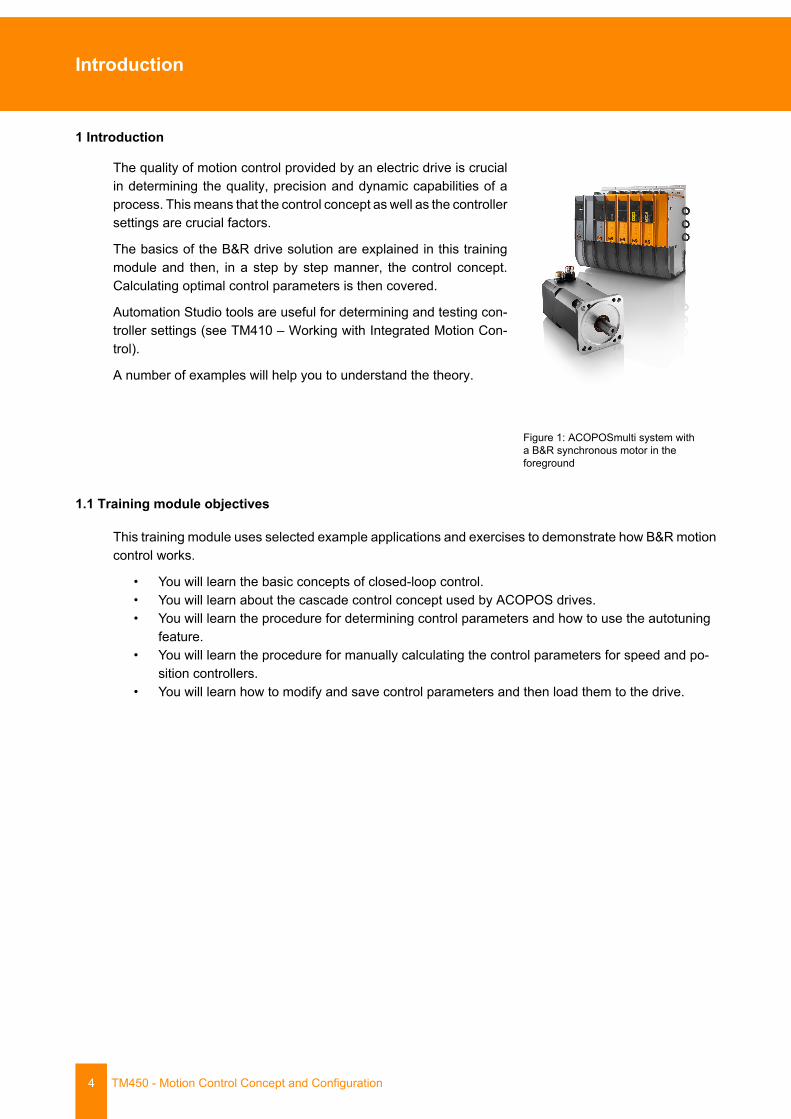
The quality of motion control provided by an electric drive is crucialin determining the quality, precision and dynamic capabilities of aprocess. This means that the control concept as well as the controllersettings are crucial factors.
The basics of the B&R drive solution are explained in this trainingmodule and then, in a step by step manner, the control concept.Calculating optimal control parameters is then covered.
Automation Studio tools are useful for determining and testing con-troller settings (see TM410 – Working with Integrated Motion Con-trol).
A number of examples will help you to understand the theory.
Figure 1: ACOPOSmulti system witha B&R synchronous motor in theforeground
1.1 Training module objectives
This training module uses selected example applications and exercises to demonstrate how B&R motioncontrol works.
• You will learn the basic concepts of closed-loop control.• You will learn about the cascade control concept used by ACOPOS drives.• You will learn the procedure for determining control parameters and how to use the autotuning
feature.• You will learn the procedure for manually calculating the control parameters for speed and po-
sition controllers.• You will learn how to modify and save control parameters and then load them to the drive.
The basics of closed-loop control
TM450 - Motion Control Concept and Configuration 5
2 The basics of closed-loop control
The following question should be asked before covering the controlconcept in more detail in the B&R drive solution:
"Why does a drive need a closed-loop control?"
The goal of a drive is to reach a position as fast and as accuratelyas possible using a motor and various mechanics.
Figure 2: ACOPOS servo drive andmotor
The first thing the controller must know is which position the motor should move to. This value is usuallyreferred to as the position setpoint. In closed-loop control, a reference variable is used to do this.
The controller requires position information to find out where the mo-tor is currently located. This information is obtained using an en-coder. The encoder is a measuring element, which provides the con-troller with the information (actual position and speed of the motor)via feedback.
If the position setpoint and the actual position don't match then thisis referred to a control deviation or a lag error.
Figure 3: Encoder information istransmitted to the ACOPOS servo drive
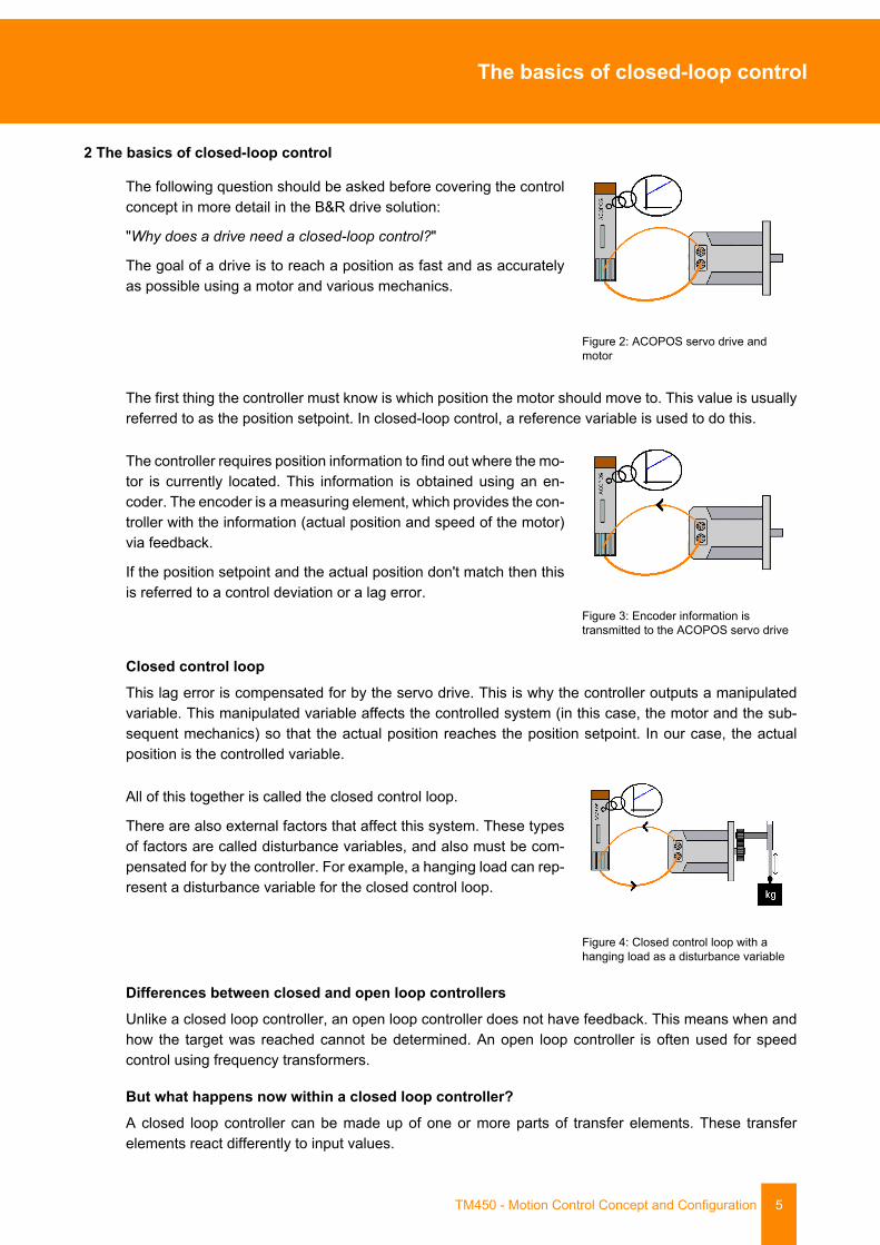
Closed control loopThis lag error is compensated for by the servo drive. This is why the controller outputs a manipulatedvariable. This manipulated variable affects the controlled system (in this case, the motor and the sub-sequent mechanics) so that the actual position reaches the position setpoint. In our case, the actualposition is the controlled variable.
All of this together is called the closed control loop.
There are also external factors that affect this system. These typesof factors are called disturbance variables, and also must be com-pensated for by the controller. For example, a hanging load can rep-resent a disturbance variable for the closed control loop.
Figure 4: Closed control loop with ahanging load as a disturbance variable
Differences between closed and open loop controllersUnlike a closed loop controller, an open loop controller does not have feedback. This means when andhow the target was reached cannot be determined. An open loop controller is often used for speedcontrol using frequency transformers.
But what happens now within a closed loop controller?A closed loop controller can be made up of one or more parts of transfer elements. These transferelements react differently to input values.

The basics of closed-loop control
6 TM450 - Motion Control Concept and Configuration
The controllers on the ACOPOS servo drive are generally made up of a proportional element (P element,P component) and an integral element (I element, I component).
P componentA P component immediately reacts to an input value jump with a proportional output value jump. Thesize of the jump on the output is determined by one factor. This gain is known as factor "kv".
Figure 5: Reaction of a P component
I componentThe output variable increases continuously in the form of a ramp if the input variable of an I componentjumps. The slope of this ramp and the rate at which the output variable ascends depends on a particulartime. This time is known as integral action time "tn".
Figure 6: Reaction of an I component
The basics of closed-loop control
TM450 - Motion Control Concept and Configuration 7
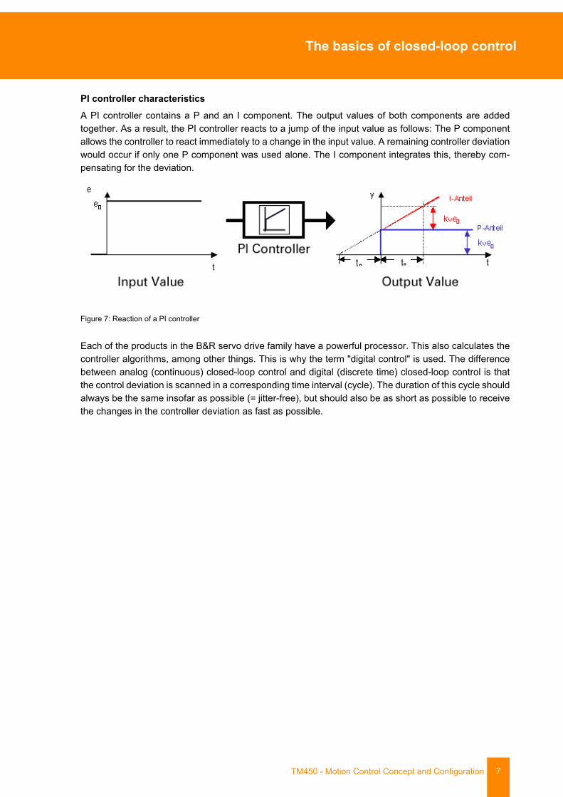
PI controller characteristicsA PI controller contains a P and an I component. The output values of both components are addedtogether. As a result, the PI controller reacts to a jump of the input value as follows: The P componentallows the controller to react immediately to a change in the input value. A remaining controller deviationwould occur if only one P component was used alone. The I component integrates this, thereby com-pensating for the deviation.
Figure 7: Reaction of a PI controller
Each of the products in the B&R servo drive family have a powerful processor. This also calculates thecontroller algorithms, among other things. This is why the term "digital control" is used. The differencebetween analog (continuous) closed-loop control and digital (discrete time) closed-loop control is thatthe control deviation is scanned in a corresponding time interval (cycle). The duration of this cycle shouldalways be the same insofar as possible (= jitter-free), but should also be as short as possible to receivethe changes in the controller deviation as fast as possible.
Cascaded control concept
8 TM450 - Motion Control Concept and Configuration
3 Cascaded control concept
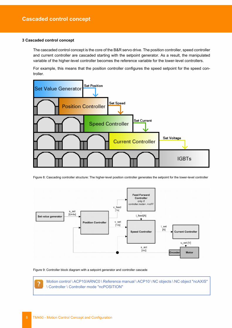
The cascaded control concept is the core of the B&R servo drive. The position controller, speed controllerand current controller are cascaded starting with the setpoint generator. As a result, the manipulatedvariable of the higher-level controller becomes the reference variable for the lower-level controllers.
For example, this means that the position controller configures the speed setpoint for the speed con-troller.
Figure 8: Cascading controller structure: The higher-level position controller generates the setpoint for the lower-level controller
Figure 9: Controller block diagram with a setpoint generator and controller cascade
Motion control \ ACP10/ARNC0 \ Reference manual \ ACP10 \ NC objects \ NC object "ncAXIS"\ Controller \ Controller mode "ncPOSITION"
Cascaded control concept
TM450 - Motion Control Concept and Configuration 9
3.1 Setpoint generator
3.1.1 Base movements
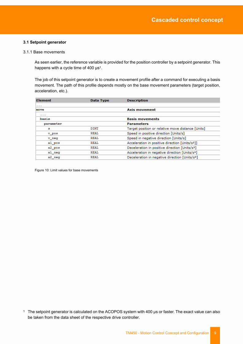
As seen earlier, the reference variable is provided for the position controller by a setpoint generator. Thishappens with a cycle time of 400 µs1.
The job of this setpoint generator is to create a movement profile after a command for executing a basismovement. The path of this profile depends mostly on the base movement parameters (target position,acceleration, etc.).
Figure 10: Limit values for base movements
1 The setpoint generator is calculated on the ACOPOS system with 400 µs or faster. The exact value can alsobe taken from the data sheet of the respective drive controller.
Cascaded control concept
10 TM450 - Motion Control Concept and Configuration
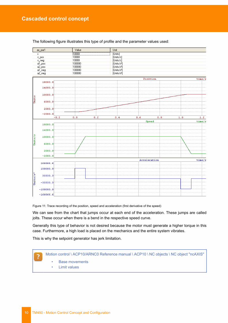
The following figure illustrates this type of profile and the parameter values used:
Figure 11: Trace recording of the position, speed and acceleration (first derivative of the speed)
We can see from the chart that jumps occur at each end of the acceleration. These jumps are calledjolts. These occur when there is a bend in the respective speed curve.
Generally this type of behavior is not desired because the motor must generate a higher torque in thiscase. Furthermore, a high load is placed on the mechanics and the entire system vibrates.
This is why the setpoint generator has jerk limitation.
Motion control \ ACP10/ARNC0 Reference manual \ ACP10 \ NC objects \ NC object "ncAXIS"
• Base movements• Limit values

Cascaded control concept
TM450 - Motion Control Concept and Configuration 11
3.1.2 Jerk limitation
The jolt occurs due to a change that causes a bend in the speed curve. If the speed is slowly increasedat the beginning or slowly reduced at the end of the acceleration phase, the rectangular accelerationprofile becomes a trapezoid. The following trace recording illustrates this:
Figure 12: Trace recording of the position, speed and acceleration with active jerk filter
A jerk filter time can be set so that the servo drive generates a jerk-limited motion profile. The jerkfilter time is the time required for acceleration from zero to the defined maximum value. Jerk limitationuses a linear filter during runtime. In the image you can see that the jerk filter time "t_jolt" was set to0.03 seconds. The measurement cursors in the lower chart diagram indicate that the rise time of theacceleration is the same as the jerk filter time.
Motion control \ ACP10/ARNC0 Reference manual \ NC \ ACP10 objects \ "ncAXIS" NC object\ Base movements
Cascaded control concept
12 TM450 - Motion Control Concept and Configuration
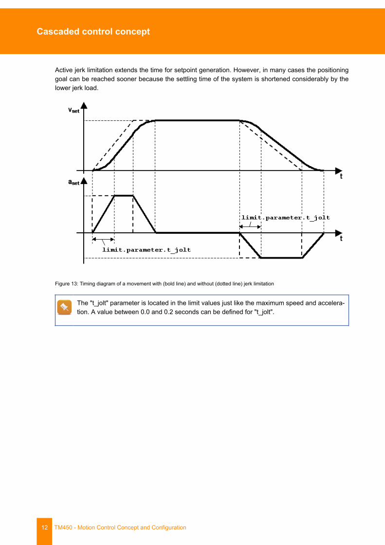
Active jerk limitation extends the time for setpoint generation. However, in many cases the positioninggoal can be reached sooner because the settling time of the system is shortened considerably by thelower jerk load.
Figure 13: Timing diagram of a movement with (bold line) and without (dotted line) jerk limitation
The "t_jolt" parameter is located in the limit values just like the maximum speed and accelera-tion. A value between 0.0 and 0.2 seconds can be defined for "t_jolt".
Cascaded control concept
TM450 - Motion Control Concept and Configuration 13
3.2 Predictive position controller
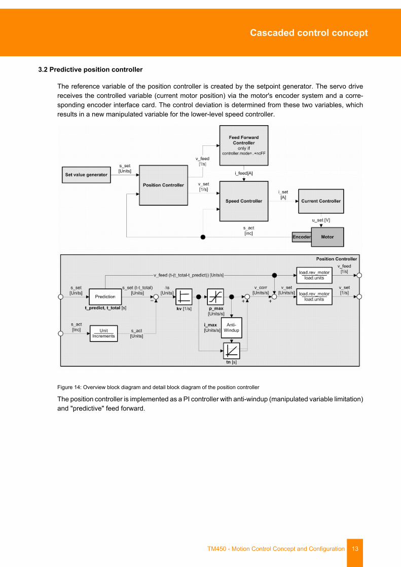
The reference variable of the position controller is created by the setpoint generator. The servo drivereceives the controlled variable (current motor position) via the motor's encoder system and a corre-sponding encoder interface card. The control deviation is determined from these two variables, whichresults in a new manipulated variable for the lower-level speed controller.
Figure 14: Overview block diagram and detail block diagram of the position controller
The position controller is implemented as a PI controller with anti-windup (manipulated variable limitation)and "predictive" feed forward.
Cascaded control concept
14 TM450 - Motion Control Concept and Configuration
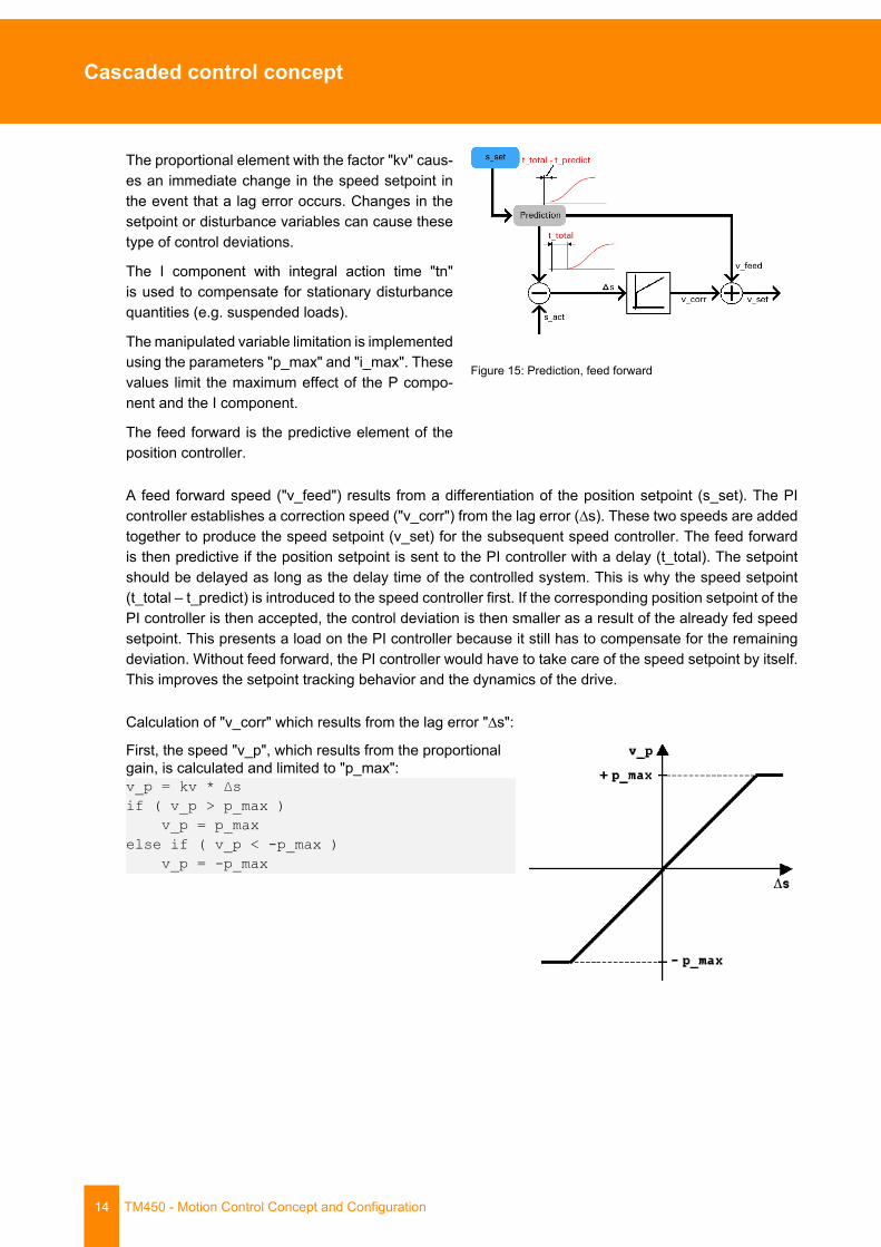
The proportional element with the factor "kv" caus-es an immediate change in the speed setpoint inthe event that a lag error occurs. Changes in thesetpoint or disturbance variables can cause thesetype of control deviations.
The I component with integral action time "tn"is used to compensate for stationary disturbancequantities (e.g. suspended loads).
The manipulated variable limitation is implementedusing the parameters "p_max" and "i_max". Thesevalues limit the maximum effect of the P compo-nent and the I component.
The feed forward is the predictive element of theposition controller.
Figure 15: Prediction, feed forward
A feed forward speed ("v_feed") results from a differentiation of the position setpoint (s_set). The PIcontroller establishes a correction speed ("v_corr") from the lag error (∆s). These two speeds are addedtogether to produce the speed setpoint (v_set) for the subsequent speed controller. The feed forwardis then predictive if the position setpoint is sent to the PI controller with a delay (t_total). The setpointshould be delayed as long as the delay time of the controlled system. This is why the speed setpoint(t_total – t_predict) is introduced to the speed controller first. If the corresponding position setpoint of thePI controller is then accepted, the control deviation is then smaller as a result of the already fed speedsetpoint. This presents a load on the PI controller because it still has to compensate for the remainingdeviation. Without feed forward, the PI controller would have to take care of the speed setpoint by itself.This improves the setpoint tracking behavior and the dynamics of the drive.
Calculation of "v_corr" which results from the lag error "∆s":
First, the speed "v_p", which results from the proportionalgain, is calculated and limited to "p_max":v_p = kv * ∆sif ( v_p > p_max ) v_p = p_maxelse if ( v_p < -p_max ) v_p = -p_max
Cascaded control concept
TM450 - Motion Control Concept and Configuration 15
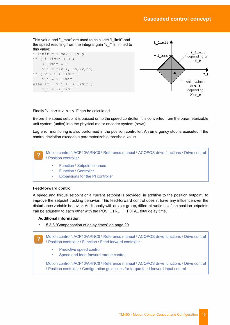
This value and "i_max" are used to calculate "i_limit" andthe speed resulting from the integral gain "v_i" is limited tothis value:i_limit = i_max - |v_p|if ( i_limit < 0 ) i_limit = 0 v_i = f(v_i, ∆s,kv,tn)if ( v_i > i_limit ) v_i = i_limitelse if ( v_i < -i_limit ) v_i = -i_limit
Finally "v_corr = v_p + v_i" can be calculated.
Before the speed setpoint is passed on to the speed controller, it is converted from the parameterizableunit system (unit/s) into the physical motor encoder system (rev/s).
Lag error monitoring is also performed in the position controller. An emergency stop is executed if thecontrol deviation exceeds a parameterizable threshold value.
Motion control \ ACP10/ARNC0 \ Reference manual \ ACOPOS drive functions \ Drive control\ Position controller
• Function \ Setpoint sources• Function \ Controller• Expansions for the PI controller
Feed-forward controlA speed and torque setpoint or a current setpoint is provided, in addition to the position setpoint, toimprove the setpoint tracking behavior. This feed-forward control doesn't have any influence over thedisturbance variable behavior. Additionally with an axis group, different runtimes of the position setpointscan be adjusted to each other with the POS_CTRL_T_TOTAL total delay time.
Additional information• 5.3.3 "Compensation of delay times" on page 29
Motion control \ ACP10/ARNC0 \ Reference manual \ ACOPOS drive functions \ Drive control\ Position controller \ Function \ Feed forward controller
• Predictive speed control• Speed and feed-forward torque control
Motion control \ ACP10/ARNC0 \ Reference manual \ ACOPOS drive functions \ Drive control\ Position controller \ Configuration guidelines for torque feed forward input control
Cascaded control concept
16 TM450 - Motion Control Concept and Configuration
3.3 Speed controller
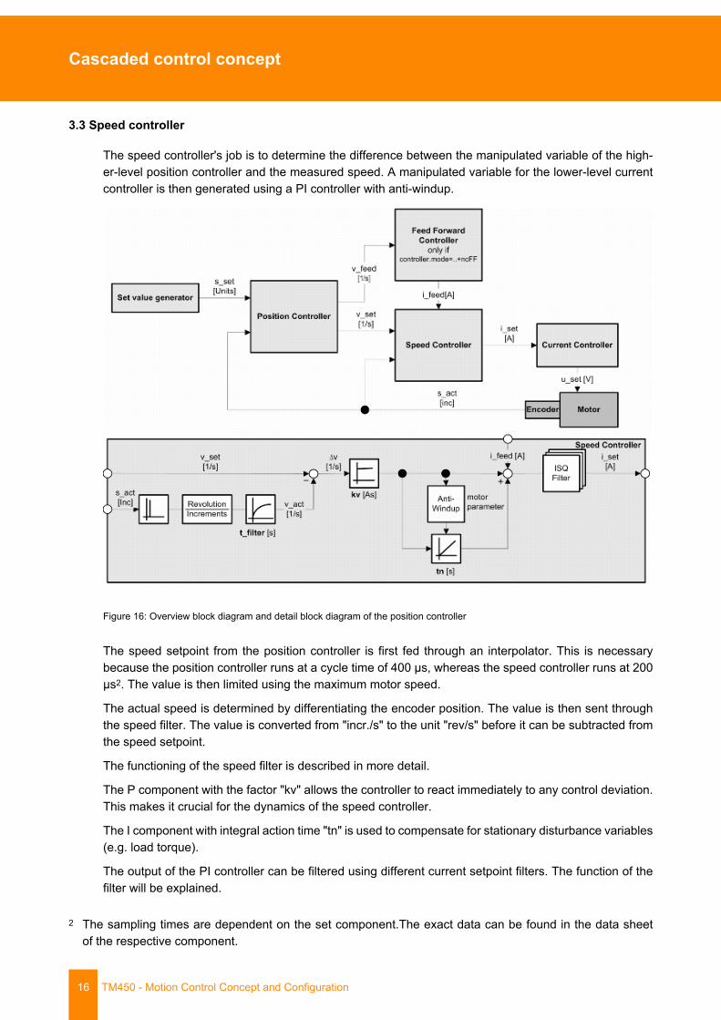
The speed controller's job is to determine the difference between the manipulated variable of the high-er-level position controller and the measured speed. A manipulated variable for the lower-level currentcontroller is then generated using a PI controller with anti-windup.
Figure 16: Overview block diagram and detail block diagram of the position controller
The speed setpoint from the position controller is first fed through an interpolator. This is necessarybecause the position controller runs at a cycle time of 400 µs, whereas the speed controller runs at 200µs2. The value is then limited using the maximum motor speed.
The actual speed is determined by differentiating the encoder position. The value is then sent throughthe speed filter. The value is converted from "incr./s" to the unit "rev/s" before it can be subtracted fromthe speed setpoint.
The functioning of the speed filter is described in more detail.
The P component with the factor "kv" allows the controller to react immediately to any control deviation.This makes it crucial for the dynamics of the speed controller.
The I component with integral action time "tn" is used to compensate for stationary disturbance variables(e.g. load torque).
The output of the PI controller can be filtered using different current setpoint filters. The function of thefilter will be explained.
2 The sampling times are dependent on the set component.The exact data can be found in the data sheetof the respective component.
Cascaded control concept
TM450 - Motion Control Concept and Configuration 17
Before the current setpoint can be provided as the reference variable for the current controller, the valueis limited using a torque limiter. This torque limitation also determines the anti-windup limits for the speedcontroller I component.
3.3.1 Torque limiting
The torque limiter is mostly used to protect the motor and the ACOPOS servo drive from the followingrisks:
• The ACOPOS servo drive cannot output more current than the motor can handle (motor peakcurrent).
• The motor's stator current cannot exceed the ACOPOS peak current.
By default, the torque limiter is pre-initialized using the smaller of the following two values:
• Motor peak current (MOTOR_CURR_MAX)• ACOPOS peak current (ACOPOS_CURR_MAX)
Motion control \ ACP10/ARNC0 \ Reference manual \ ACOPOS drive functions \ Drive control\ Torque limiter
Motion control \ ACP10/ARNC0 \ Reference manual \ ACOPOS drive functions \ Motor \ Syn-chronous motor
Motion control \ ACP10/ARNC0 \ Libraries \ ACP10_MC \ Categorized function blocks \ Torquecontrol \ Torque limiting
3.3.2 Current setpoint filter
The current setpoint filter ISQ_FILTER is made up of a cascade of up to three different filters. Thefilter cascade is placed on the speed controller input and filters the quadrature current setpoint isq. Forexample, the filters serve to separate very frequent disturbances (e.g. signal interference) from a wantedsignal or to suppress resonant frequencies (band-stop filter).
Disturbance in the encoder signal can be caused by one or more of the following:
• Coupling of disturbances on the communication path (encoder cable).• Quantization interference when converting the analog signal to digital form. This mostly occurs
when evaluating a resolver signal with low resolution.
With warp-resistant drive mechanics (e.g. direct load coupling to the motor shaft using fastening devices),the mechanical system can be subject to oscillations due to closed control loop ("two-mass oscillation").These types of systems generally have a resonance frequency in the range from 700 to 1500 Hz. Fur-thermore, this is dependent on the following factors:
• Rigidity of the mechanical system• Mass inertia of the mechanical system• Physical layout of the system
Speed filterThe actual speed is filtered before it is processed further in the speed controller. This filter is known asa "speed filter" and functions like a low pass. High-frequency disturbances can be filtered out from thespeed signal using this low pass behavior. This makes it possible to achieve higher controller quality.
Cascaded control concept
18 TM450 - Motion Control Concept and Configuration
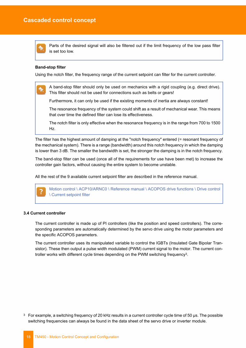
Parts of the desired signal will also be filtered out if the limit frequency of the low pass filteris set too low.
Band-stop filterUsing the notch filter, the frequency range of the current setpoint can filter for the current controller.
A band-stop filter should only be used on mechanics with a rigid coupling (e.g. direct drive).This filter should not be used for connections such as belts or gears!
Furthermore, it can only be used if the existing moments of inertia are always constant!
The resonance frequency of the system could shift as a result of mechanical wear. This meansthat over time the defined filter can lose its effectiveness.
The notch filter is only effective when the resonance frequency is in the range from 700 to 1500Hz.
The filter has the highest amount of damping at the "notch frequency" entered (= resonant frequency ofthe mechanical system). There is a range (bandwidth) around this notch frequency in which the dampingis lower than 3 dB. The smaller the bandwidth is set, the stronger the damping is in the notch frequency.
The band-stop filter can be used (once all of the requirements for use have been met) to increase thecontroller gain factors, without causing the entire system to become unstable.
All the rest of the 9 available current setpoint filter are described in the reference manual.
Motion control \ ACP10/ARNC0 \ Reference manual \ ACOPOS drive functions \ Drive control\ Current setpoint filter
3.4 Current controller
The current controller is made up of PI controllers (like the position and speed controllers). The corre-sponding parameters are automatically determined by the servo drive using the motor parameters andthe specific ACOPOS parameters.
The current controller uses its manipulated variable to control the IGBTs (Insulated Gate Bipolar Tran-sistor). These then output a pulse width modulated (PWM) current signal to the motor. The current con-troller works with different cycle times depending on the PWM switching frequency3.
3 For example, a switching frequency of 20 kHz results in a current controller cycle time of 50 µs. The possibleswitching frequencies can always be found in the data sheet of the servo drive or inverter module.
Theoretically determining control parameters
TM450 - Motion Control Concept and Configuration 19
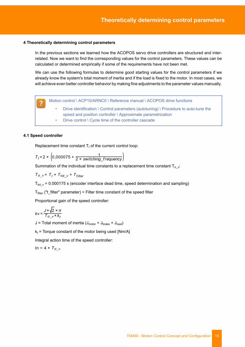
4 Theoretically determining control parameters
In the previous sections we learned how the ACOPOS servo drive controllers are structured and inter-related. Now we want to find the corresponding values for the control parameters. These values can becalculated or determined empirically if some of the requirements have not been met.
We can use the following formulas to determine good starting values for the control parameters if wealready know the system's total moment of inertia and if the load is fixed to the motor. In most cases, wewill achieve even better controller behavior by making fine adjustments to the parameter values manually.
Motion control \ ACP10/ARNC0 \ Reference manual \ ACOPOS drive functions
• Drive identification \ Control parameters (autotuning) \ Procedure to auto-tune thespeed and position controller \ Approximate parametrization
• Drive control \ Cycle time of the controller cascade
4.1 Speed controller
Replacement time constant TI of the current control loop:
Summation of the individual time constants to a replacement time constant Tσ_v:
Ttot_v = 0.000175 s (encoder interface dead time, speed determination and sampling)
Tfilter ("t_filter" parameter) = Filter time constant of the speed filter
Proportional gain of the speed controller:
J = Total moment of inertia (Jmotor + Jbrake + Jload)
kt = Torque constant of the motor being used [Nm/A]
Integral action time of the speed controller:
Theoretically determining control parameters
20 TM450 - Motion Control Concept and Configuration
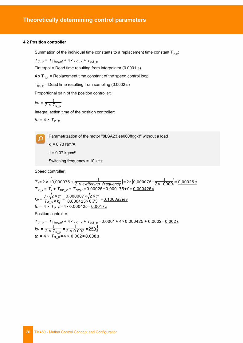
4.2 Position controller
Summation of the individual time constants to a replacement time constant Tσ_p:
Tinterpol = Dead time resulting from interpolator (0.0001 s)
4 x Tσ_v = Replacement time constant of the speed control loop
Ttot_p = Dead time resulting from sampling (0.0002 s)
Proportional gain of the position controller:
Integral action time of the position controller:
Parametrization of the motor "8LSA23.ee060ffgg-3" without a load
kt = 0.73 Nm/A
J = 0.07 kgcm²
Switching frequency = 10 kHz
Speed controller:
Position controller:

Procedure for tuning the controller
TM450 - Motion Control Concept and Configuration 21
5 Procedure for tuning the controller
In this section we will learn about a possibility for determining control parameters, which has been proventime and time again in the field. This will allow you to check and make fine adjustments to values thathave already been calculated. If this is not possible, suitable values can be determined empirically. Inthis case, the values specified in the corresponding notes can be used as start values.
The autotuning functions can be used to ease the calculation of the controller settings (see 6 "Determin-ing control settings using autotuning" on page 38).
Motion control \ ACP10/ARNC0 \ Reference manual \ ACOPOS drive functions \ Drive identifi-cation \ Controller parameters (autotuning) \ Sequence autotuning speed and position controller
• Approximate parameter settings
Motion control \ ACP10/ARNC0 \ Commissioning \ Autotuning
5.1 General information
The control parameters only really have to be determined when the mechanics are already put together.When dealing with a machine where the axis is loaded with different masses, the parameters must betested both without a load and with the highest load. The parameters should also be tested at differentspeeds and accelerations.
These tests could result in the need for a compromise.
Globally valid values for the control parameters cannot be used because all mechanics have differentfeatures.
To determine parameters of cascaded controllers, it is best to start from the bottom (last) controller andwork up. In our case, this means that we would start by setting the speed controller first followed by theposition controller. The current controller is automatically parametrized by the ACOPOS servo drive.
Figure 17: Order for setting the controllers
It is usually the goal to set the controller as "hard" as possible. A controller can be considered "hard"when a disturbance variable is compensated for as quickly and perfectly as possible.
Procedure for tuning the controller
22 TM450 - Motion Control Concept and Configuration
We want to manually rotate a flywheel mass which is mounted to the motor shaft.
• The controllers are set "soft" if the flywheel mass can be easily rotated.• The controllers are set "hard" if the flywheel mass is difficult to rotate or cannot be ro-
tated at all.
However, sometimes it is not the goal to set the controller as hard as possible. This is because a hardclosed-loop control can cause quick heating, a higher load on the mechanics and therefore more wear.This is the reason why a compromise must often be found when determining the parameters.
We will be using the NC test window to help us set the control parameters. This allows us to change andinitialize the control parameters online. This also makes it possible to start positioning movements usingany base motion parameters. We can also configure, start and evaluate the trace in the NC test window.
The behavior of the controller during a typical movement can be estimated very accurately by selectingsuitable parameters for tracing. Therefore, a base movement (e.g. relative or absolute movement) isusually started and the corresponding parameters are recorded.
Furthermore, the control parameters should be selected so that oscillation in the recorded values is keptto a minimum.
Procedure for tuning the controller
TM450 - Motion Control Concept and Configuration 23
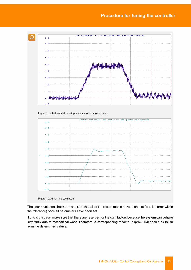
Figure 18: Stark oscillation – Optimization of settings required
Figure 19: Almost no oscillation
The user must then check to make sure that all of the requirements have been met (e.g. lag error withinthe tolerance) once all parameters have been set.
If this is the case, make sure that there are reserves for the gain factors because the system can behavedifferently due to mechanical wear. Therefore, a corresponding reserve (approx. 1/3) should be takenfrom the determined values.
Procedure for tuning the controller
24 TM450 - Motion Control Concept and Configuration
5.2 Speed controller
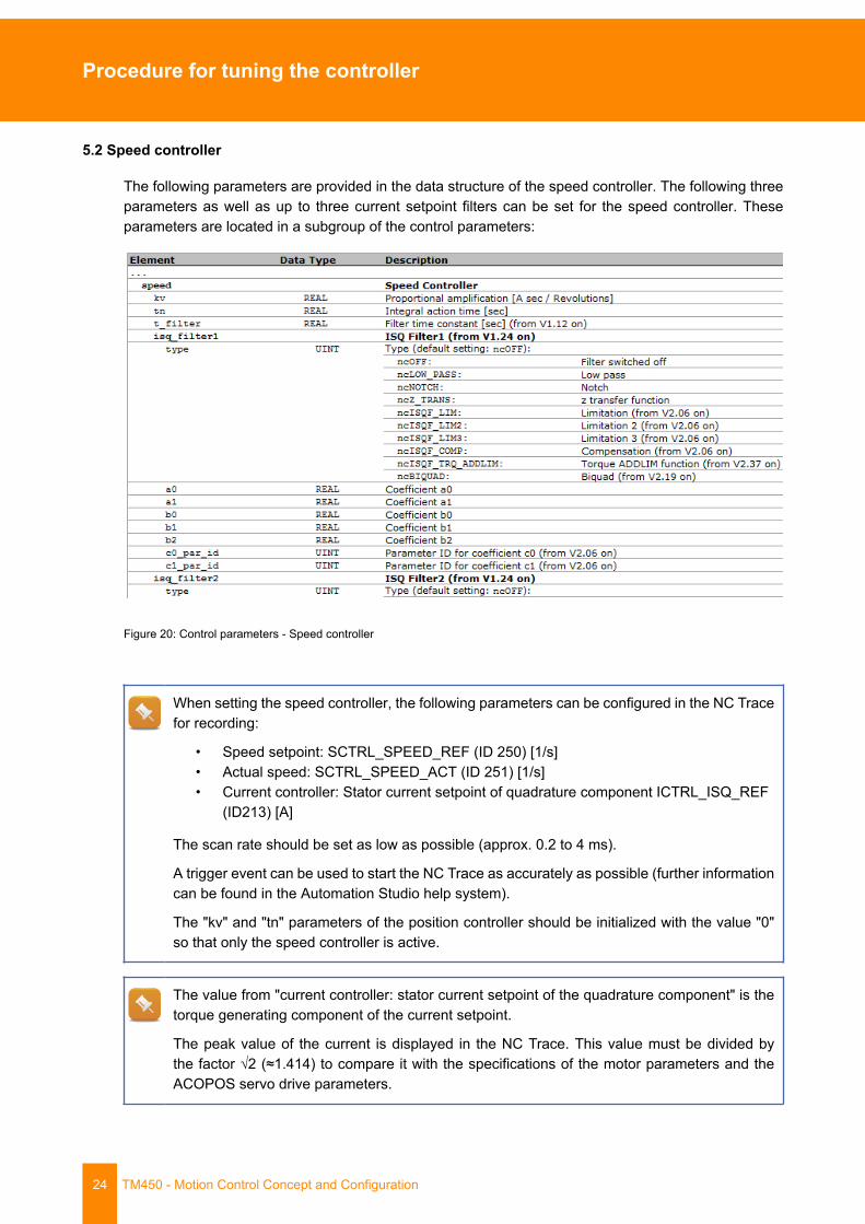
The following parameters are provided in the data structure of the speed controller. The following threeparameters as well as up to three current setpoint filters can be set for the speed controller. Theseparameters are located in a subgroup of the control parameters:
Figure 20: Control parameters - Speed controller
When setting the speed controller, the following parameters can be configured in the NC Tracefor recording:
• Speed setpoint: SCTRL_SPEED_REF (ID 250) [1/s]• Actual speed: SCTRL_SPEED_ACT (ID 251) [1/s]• Current controller: Stator current setpoint of quadrature component ICTRL_ISQ_REF
(ID213) [A]
The scan rate should be set as low as possible (approx. 0.2 to 4 ms).
A trigger event can be used to start the NC Trace as accurately as possible (further informationcan be found in the Automation Studio help system).
The "kv" and "tn" parameters of the position controller should be initialized with the value "0"so that only the speed controller is active.
The value from "current controller: stator current setpoint of the quadrature component" is thetorque generating component of the current setpoint.
The peak value of the current is displayed in the NC Trace. This value must be divided bythe factor √2 (≈1.414) to compare it with the specifications of the motor parameters and theACOPOS servo drive parameters.

Procedure for tuning the controller
TM450 - Motion Control Concept and Configuration 25
Motion control \ ACP10/ARNC0 \ Reference manual \ ACP10 \ ACOPOS parameter IDs \
• CTRL speed• CTRL current
Motion control \ ACP10/ARNC0 Reference manual \ NC \ ACP10 objects \ "ncAXIS" NC object\ Closed-loop controller \ Data structure
Motion control \ ACP10/ARNC0 \ NC Diagnose \ NC Trace \ Configuration
5.2.1 Proportional gain "kv"
The most important parameter of the speed controller parameters is the gain factor "kv". This parametersignificantly determines the dynamic properties of this controller. The goal is to set the value as largeas possible without causing the system to oscillate.
1/5 to 1/10 of the nominal motor current (In) can be used as starting value for this factor.
Example:
Difference between the speed setpoint and the actualspeed:
1 rev/s
Value of the factor "kv": 2 As/rev
Output value of the P component: 2 A
5.2.2 Integral action time "tn"
For most applications it is not necessary to use an integral action time in the speed controller ("tn" = 0s). However, this time value should not be set too low if an application does require an I component (e.g.to compensate for load-side disturbances, poor (soft) load coupling, high speed precision). Otherwise,the tendency for oscillation is increased in the speed controller.
100 ms (0.1 s) can be used as starting value for the integral action time if you want to use theI component. The value can then be gradually reduced.
5.2.3 Speed filter
The filter time constant "t_filter" for the speed filter is the last parameter in the speed control parameters.It can be used to set the limit frequency with the unit [s] (e.g. 1 kHz equals 0.001 s).
Improvement to the controller behavior using the speed filter can only be achieved in systems with a highmass moment of inertia and encoder systems with a low resolution (e.g. resolver). Whereas if encodersystems with a high resolution are used, the speed filter generally cannot create any improvements inthe controller behavior.
Procedure for tuning the controller
26 TM450 - Motion Control Concept and Configuration
You can start with a value of 0.8 ms (0.0008 s). This value can be then be gradually increaseduntil the controller behavior (reduced oscillation) has improved. Generally, the usable valuesare in the range from 0.8 ms to 2 ms.
5.2.4 Motion control \ ACP10/ARNC0 Current setpoint filter
The current setpoint filters (e.g. band-stop filter) also work in the speed controller.
Motion control \ ACP10/ARNC0 \ Reference manual \ ACOPOS drive functions \ Drive control\ Current setpoint filter
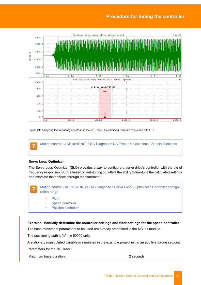
Determining parameters for band-stop filterThe resonance frequency of the system can be determined using the following steps:
• Initialize the position controller parameters with the value "0", deactivate the speed filter (t_filter= 0) and deactivate the current setpoint filter.
• Switch on controller.• The proportional gain of the speed controller is increased until the mechanics oscillate.• Record the actual speed using the trace (scan rate = 200 µs). Switch the controller off again
when the trace has finished.• Analyze the frequency spectrum in the trace using FFT (Fast Fourier Transformation).• Set the most notable frequency occurring in the trace as notch frequency for the band-stop fil-
ter.• Enter a minimum bandwidth (e.g. 25 Hz).• Switch the controller on again and determine a critical proportional gain for the speed con-
troller.• If the critical value has increased, determine if the behavior has further improved due to vari-
ation in the bandwidth and the notch frequency. Otherwise, determine a characteristic naturalfrequency again.
• If further improvement is no longer possible, the determined values can be entered in, for ex-ample, the NC Init module or the mapp configuration for the MpAxisBasic component.
The band-stop filter cannot be used if a distinct resonant frequency cannot be determined.
Procedure for tuning the controller
TM450 - Motion Control Concept and Configuration 27
Figure 21: Analyzing the frequency spectrum in the NC Trace - Determining resonant frequency with FFT
Motion control \ ACP10/ARNC0 \ NC Diagnose \ NC Trace \ Calculations \ Special functions
Servo Loop OptimizerThe Servo Loop Optimizer (SLO) provides a way to configure a servo drive's controller with the aid offrequency responses. SLO is based on autotuning but offers the ability to fine-tune the calculated settingsand examine their effects through measurement.
Motion control \ ACP10/ARNC0 \ NC Diagnose \ Servo Loop \ Optimizer \ Controller configu-ration range
• Plant• Speed controller• Position controller
Exercise: Manually determine the controller settings and filter settings for the speed controllerThe base movement parameters to be used are already predefined in the NC Init module.
The positioning path is "s" = ± 50000 units
A stationary manipulated variable is simulated in the example project using an additive torque setpoint.
Parameters for the NC Trace:
Maximum trace duration: 2 seconds

Procedure for tuning the controller
28 TM450 - Motion Control Concept and Configuration
Sampling rate: 0.0008 seconds
Use the flow chart (see 5.5 "Overview for setting control parameters") to set the speed controller in steps.
1) What happens in this case if the value "0" is entered for the position control parameter "kv"?
2) Can a band-stop filter be used/set as a current setpoint filter?
3) Can the speed filter be used/set?
4) Would you set an integral action time "tn" for the speed controller?
5.3 Position controller
The parameters for setting the position controller are located in a subgroup of the control parameters:
Figure 22: Control parameters - Position controller
The following parameters can be configured for recording with the NC Trace when setting theposition controller:
• Actual speed of the position controller: PCTRL_V_ACT (ID 92) [units/s]• Lag error of the position controller: PCTRL_LAG_ERROR (ID112) [units]• Quadrature component of the current controller stator current setpoint: ICTR-
L_ISQ_ACT (ID214) [A]
The sampling rate should be set as low as possible in this case as well.
Motion control \ ACP10/ARNC0 \ Reference manual \ ACP10 \ ACOPOS parameter IDs
• CTRL position controller• CTRL current
Motion control \ ACP10/ARNC0 \ Reference manual \ ACOPOS drive functions \ Drive control\ Position controller
5.3.1 Proportional gain "kv"
The value of the "kv" factor should also be set as large as possible for the position controller withoutcausing the controller to oscillate.

Procedure for tuning the controller
TM450 - Motion Control Concept and Configuration 29
You can start with a value of 50/s and increase it gradually.
Lag error: 15 units
Value of the factor "kv": 100/s
Output value of the P component: 1,500 Units/sec
5.3.2 Integral action time "tn"
Similar conditions also apply for this value as for the integral action time of the speed controller. For someapplications it is sufficient to just use just one P controller. An I component must be used if an axis has tocompensate for a stationary disturbance variable (e.g. hanging load). Furthermore, it may be necessaryto use the I component of the position controller if the speed controller was only able to be set soft.
The integral action time does not have to be set for the position controller if already set for the speedcontroller.
You can also use a starting value of 100 ms if necessary in this case.
An I component in the position controller causes oscillation when the target position is reachedand therefore should only be used in special cases.
5.3.3 Compensation of delay times
Transferring data from a coupling master to a coupling slave via a network results in a delay. This canbe compensated on the coupling master using the position controller parameter for total delay time("t_total"). Details regarding the compensation of delay times and how they are calculated can be foundin the "Calculation of delay times" table. The table is provided in Automation Help as a download.
It is necessary to configure a broadcast channel in order to couple an axis to setpoints that originatefrom outside of the network.
Motion control \ ACP10/ARNC0 \ Libraries \ ACP10_MC \ Categorized function blocks \ Impor-tant points \ Axis coupling
• Compensation of delay times• Coupling axes to different networks
Procedure for tuning the controller
30 TM450 - Motion Control Concept and Configuration
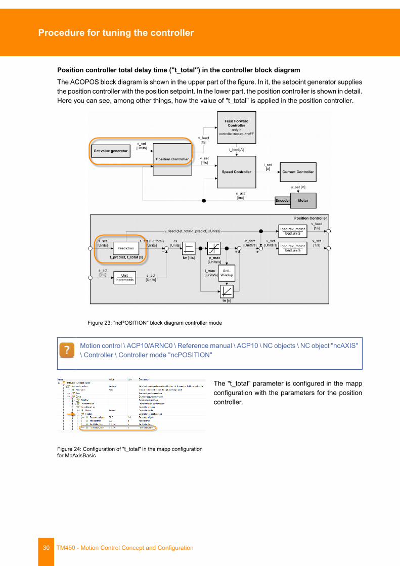
Position controller total delay time ("t_total") in the controller block diagramThe ACOPOS block diagram is shown in the upper part of the figure. In it, the setpoint generator suppliesthe position controller with the position setpoint. In the lower part, the position controller is shown in detail.Here you can see, among other things, how the value of "t_total" is applied in the position controller.
Figure 23: "ncPOSITION" block diagram controller mode
Motion control \ ACP10/ARNC0 \ Reference manual \ ACP10 \ NC objects \ NC object "ncAXIS"\ Controller \ Controller mode "ncPOSITION"
Figure 24: Configuration of "t_total" in the mapp configurationfor MpAxisBasic
The "t_total" parameter is configured in the mappconfiguration with the parameters for the positioncontroller.
Procedure for tuning the controller
TM450 - Motion Control Concept and Configuration 31
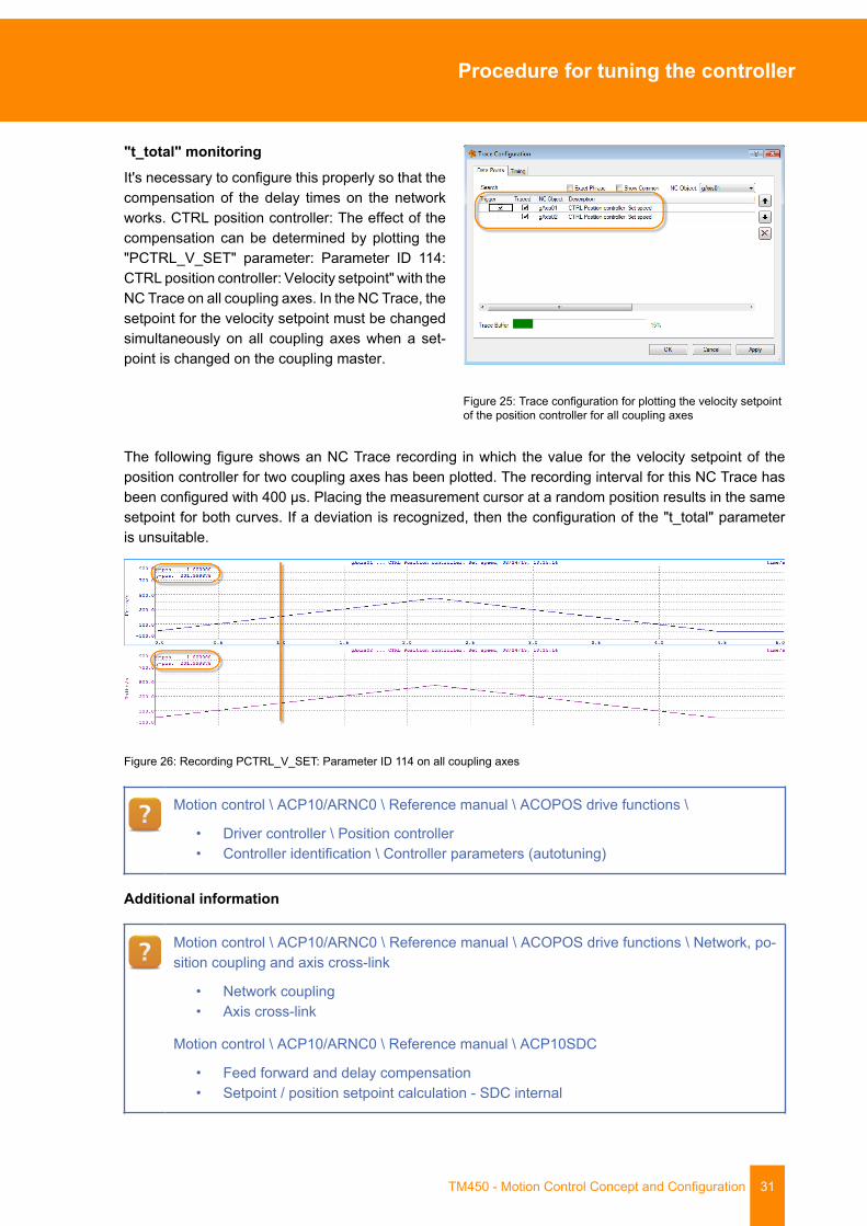
"t_total" monitoringIt's necessary to configure this properly so that thecompensation of the delay times on the networkworks. CTRL position controller: The effect of thecompensation can be determined by plotting the"PCTRL_V_SET" parameter: Parameter ID 114:CTRL position controller: Velocity setpoint" with theNC Trace on all coupling axes. In the NC Trace, thesetpoint for the velocity setpoint must be changedsimultaneously on all coupling axes when a set-point is changed on the coupling master.
Figure 25: Trace configuration for plotting the velocity setpointof the position controller for all coupling axes
The following figure shows an NC Trace recording in which the value for the velocity setpoint of theposition controller for two coupling axes has been plotted. The recording interval for this NC Trace hasbeen configured with 400 µs. Placing the measurement cursor at a random position results in the samesetpoint for both curves. If a deviation is recognized, then the configuration of the "t_total" parameteris unsuitable.
Figure 26: Recording PCTRL_V_SET: Parameter ID 114 on all coupling axes
Motion control \ ACP10/ARNC0 \ Reference manual \ ACOPOS drive functions \
• Driver controller \ Position controller• Controller identification \ Controller parameters (autotuning)
Additional information
Motion control \ ACP10/ARNC0 \ Reference manual \ ACOPOS drive functions \ Network, po-sition coupling and axis cross-link
• Network coupling• Axis cross-link
Motion control \ ACP10/ARNC0 \ Reference manual \ ACP10SDC
• Feed forward and delay compensation• Setpoint / position setpoint calculation - SDC internal

Procedure for tuning the controller
32 TM450 - Motion Control Concept and Configuration
5.3.3.1 Total delay time "t_total"
In a single-axis application, this parameter should be initialized with the same value as the predictiontime.
The delay via the network can be compensated using the "t_total" in multi-axis applications.
The potential value range is also as large as in the parameter "t_predict".
5.3.3.2 Prediction time "t_predict"
This parameter is required for the feed forward. A value "t_predict = 0 s" disables the feed forward.
The prediction time makes it possible to compensate for the lag error during the acceleration and de-celeration phase to approximately "0". This parameter is generally set after correct values have beendetermined for "kv" and "tn".
The potential value range of the "t_predict" parameter is 0.0 to 0.06 seconds.
Generally, a large prediction time is not really necessary if the speed controller could be sethard.
Definition rule:
J = Moment of inertia on the motor [kgm²]
kvspeed controller = Proportional gain of the speed controller [As/rev.]
kt = Torque constant of the motor being used [Nm/A]
The following charts display the lag error for different prediction time values.
Corresponding speed profile:
Figure 27: Speed curve for the following lag error curves
Procedure for tuning the controller
TM450 - Motion Control Concept and Configuration 33
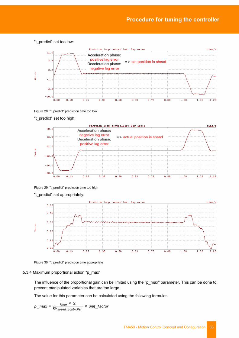
"t_predict" set too low:
Figure 28: "t_predict" prediction time too low
"t_predict" set too high:
Figure 29: "t_predict" prediction time too high
"t_predict" set appropriately:
Figure 30: "t_predict" prediction time appropriate
5.3.4 Maximum proportional action "p_max"
The influence of the proportional gain can be limited using the "p_max" parameter. This can be done toprevent manipulated variables that are too large.
The value for this parameter can be calculated using the following formulas:
Procedure for tuning the controller
34 TM450 - Motion Control Concept and Configuration
Imax = Motor peak current [A]
kvspeed controller = Proportional gain of the speed controller [As/rev.]
Unit factor = Unit scaling [units/rev.]
5.3.5 Maximum integral action "i_max"
The maximum influence of the integral element can be limited using the "i_max" parameter. This canbe done to prevent a "windup".
The value for this parameter can be calculated using the following formula to achieve a required holdingtorque:
M = Required holding torque [Nm]
kt = Torque constant of the motor being used [Nm/A]
kvspeed controller = Proportional gain of the speed controller [As/rev.]
Unit factor = Unit scaling [units/rev.]
Exercise: Manually determine the controller settings for the position controllerThe same project and same hardware are used for this exercise as before.
The base movement parameters to be used are already defined in the NC Init module.
Positioning path "s" = ± 50000 units
A stationary manipulated variable is simulated in the example project using an additive torque setpoint.
Parameters for the trace:
Max. trace duration: 2 seconds
Sampling rate: 0.0008 seconds
Use the flow chart (see 5.5 "Overview for setting control parameters") to set the position controller stepby step. The values of the speed controller obtained in the previous exercise form the basis.
1) What happens if you don't use an integral action time "tn" for the position controller?
Motion control \ ACP10/ARNC0 \ Reference manual \ ACOPOS drive functions \ Drive control\ Position controller \ Function \ Closed-loop controller
5.4 Limit value parameter
When the control parameters are optimized, two parameters must still be set for the limit values.

Procedure for tuning the controller
TM450 - Motion Control Concept and Configuration 35
5.4.1 "t_jolt” jerk time filter
The value for the parameter can be determined by recording the lag error during a positioning movementwithout jerk filter time. At the end of this movement, it will become evident that the system must first"settle down". After being determined from the trace, the settling time (time until oscillation levels out)can now be used as jerk filter time "t_jolt".
Figure 31: Calculating "t_jolt" jerk time by observing the lag error in the position controller
5.4.2 Lag error cancellation limit
The two limits "ds_warning" and "ds_stop" are de-fined for lag error monitoring (difference betweenactual position and position setpoint in positioncontroller).
Figure 32: Limit value parameter - Lag error cancellation limit
A warning is output if the current lag error value set for the "ds_warning" parameter is exceeded. Anemergency stop is executed if the value of the "ds_stop" parameter is also exceeded.
Procedure for tuning the controller
36 TM450 - Motion Control Concept and Configuration
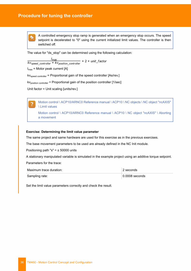
A controlled emergency stop ramp is generated when an emergency stop occurs. The speedsetpoint is decelerated to "0" using the current initialized limit values. The controller is thenswitched off.
The value for "ds_stop" can be determined using the following calculation:
Imax = Motor peak current [A]
kvspeed controller = Proportional gain of the speed controller [As/rev.]
kvposition controller = Proportional gain of the position controller [1/sec]
Unit factor = Unit scaling [units/rev.]
Motion control \ ACP10/ARNC0 Reference manual \ ACP10 \ NC objects \ NC object "ncAXIS"\ Limit values
Motion control \ ACP10/ARNC0 Reference manual \ ACP10 \ NC object "ncAXIS" \ Abortinga movement
Exercise: Determining the limit value parameterThe same project and same hardware are used for this exercise as in the previous exercises.
The base movement parameters to be used are already defined in the NC Init module.
Positioning path "s" = ± 50000 units
A stationary manipulated variable is simulated in the example project using an additive torque setpoint.
Parameters for the trace:
Maximum trace duration: 2 seconds
Sampling rate: 0.0008 seconds
Set the limit value parameters correctly and check the result.

Procedure for tuning the controller
TM450 - Motion Control Concept and Configuration 37
5.5 Overview for setting control parameters
Figure 33: Overview of the process for setting the control parameters
Determining control settings using autotuning
38 TM450 - Motion Control Concept and Configuration
6 Determining control settings using autotuning
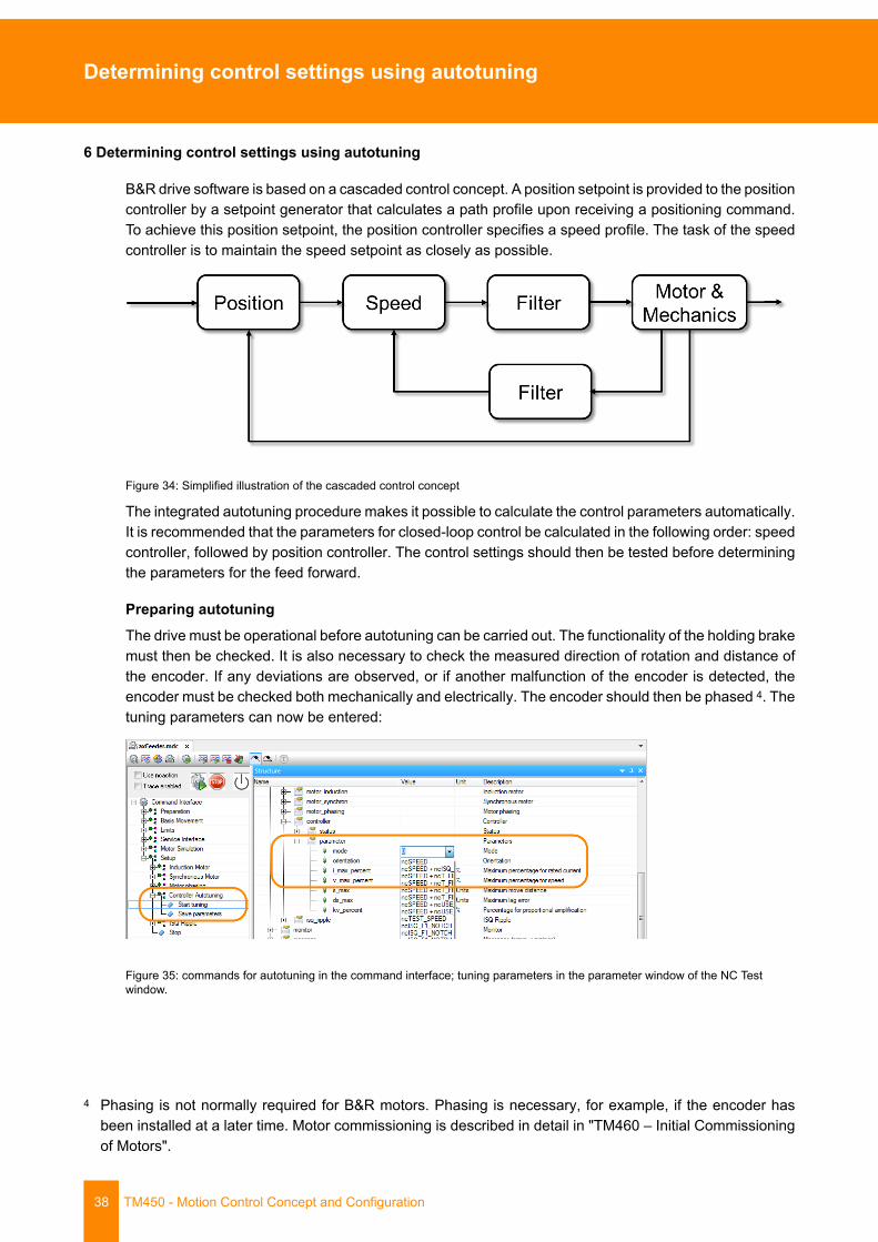
B&R drive software is based on a cascaded control concept. A position setpoint is provided to the positioncontroller by a setpoint generator that calculates a path profile upon receiving a positioning command.To achieve this position setpoint, the position controller specifies a speed profile. The task of the speedcontroller is to maintain the speed setpoint as closely as possible.
Figure 34: Simplified illustration of the cascaded control concept
The integrated autotuning procedure makes it possible to calculate the control parameters automatically.It is recommended that the parameters for closed-loop control be calculated in the following order: speedcontroller, followed by position controller. The control settings should then be tested before determiningthe parameters for the feed forward.
Preparing autotuningThe drive must be operational before autotuning can be carried out. The functionality of the holding brakemust then be checked. It is also necessary to check the measured direction of rotation and distance ofthe encoder. If any deviations are observed, or if another malfunction of the encoder is detected, theencoder must be checked both mechanically and electrically. The encoder should then be phased 4. Thetuning parameters can now be entered:
Figure 35: commands for autotuning in the command interface; tuning parameters in the parameter window of the NC Testwindow.
4 Phasing is not normally required for B&R motors. Phasing is necessary, for example, if the encoder hasbeen installed at a later time. Motor commissioning is described in detail in "TM460 – Initial Commissioningof Motors".
Determining control settings using autotuning
TM450 - Motion Control Concept and Configuration 39
A suitable NC Trace configuration for analyzing each phase of the autotuning procedure isavailable in the "Motion control \ ACP10/ARNC0 \ Commissioning \ Autotuning" section of Au-tomation Help.
Tune the cooling outputThe speed controller's job is to determine the difference between the manipulated variable of the positioncontroller (to which it is subordinate) and the measured speed. This calculates a manipulated variablefor the subordinate current controller that works against a deviation in the speed by accelerating.
Selecting the "ncSPEED" autotuning mode5 and restarting the tuning procedure from the commandinterface will determine the parameters for the speed controller.
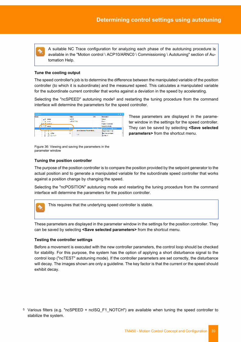
Figure 36: Viewing and saving the parameters in theparameter window
These parameters are displayed in the parame-ter window in the settings for the speed controller.They can be saved by selecting <Save selectedparameters> from the shortcut menu.
Tuning the position controllerThe purpose of the position controller is to compare the position provided by the setpoint generator to theactual position and to generate a manipulated variable for the subordinate speed controller that worksagainst a position change by changing the speed.
Selecting the "ncPOSITION" autotuning mode and restarting the tuning procedure from the commandinterface will determine the parameters for the position controller.
This requires that the underlying speed controller is stable.
These parameters are displayed in the parameter window in the settings for the position controller. Theycan be saved by selecting <Save selected parameters> from the shortcut menu.
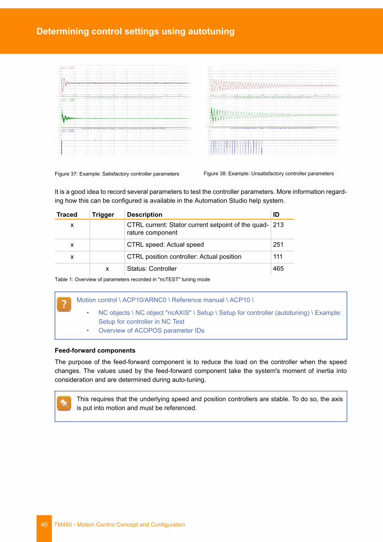
Testing the controller settingsBefore a movement is executed with the new controller parameters, the control loop should be checkedfor stability. For this purpose, the system has the option of applying a short disturbance signal to thecontrol loop ("ncTEST" autotuning mode). If the controller parameters are set correctly, the disturbancewill decay. The images shown are only a guideline. The key factor is that the current or the speed shouldexhibit decay.
5 Various filters (e.g. "ncSPEED + ncISQ_F1_NOTCH") are available when tuning the speed controller tostabilize the system.
Determining control settings using autotuning
40 TM450 - Motion Control Concept and Configuration
Figure 37: Example: Satisfactory controller parameters Figure 38: Example: Unsatisfactory controller parameters
It is a good idea to record several parameters to test the controller parameters. More information regard-ing how this can be configured is available in the Automation Studio help system.
Traced Trigger Description IDx CTRL current: Stator current setpoint of the quad-
rature component213
x CTRL speed: Actual speed 251
x CTRL position controller: Actual position 111
x Status: Controller 465Table 1: Overview of parameters recorded in "ncTEST" tuning mode
Motion control \ ACP10/ARNC0 \ Reference manual \ ACP10 \
• NC objects \ NC object "ncAXIS" \ Setup \ Setup for controller (autotuning) \ Example:Setup for controller in NC Test
• Overview of ACOPOS parameter IDs
Feed-forward componentsThe purpose of the feed-forward component is to reduce the load on the controller when the speedchanges. The values used by the feed-forward component take the system's moment of inertia intoconsideration and are determined during auto-tuning.
This requires that the underlying speed and position controllers are stable. To do so, the axisis put into motion and must be referenced.
Determining control settings using autotuning
TM450 - Motion Control Concept and Configuration 41
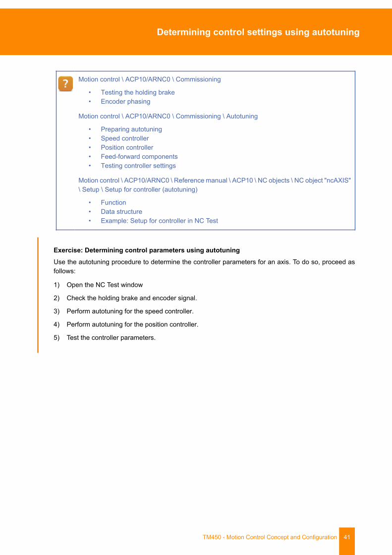
Motion control \ ACP10/ARNC0 \ Commissioning
• Testing the holding brake• Encoder phasing
Motion control \ ACP10/ARNC0 \ Commissioning \ Autotuning
• Preparing autotuning• Speed controller• Position controller• Feed-forward components• Testing controller settings
Motion control \ ACP10/ARNC0 \ Reference manual \ ACP10 \ NC objects \ NC object "ncAXIS"\ Setup \ Setup for controller (autotuning)
• Function• Data structure• Example: Setup for controller in NC Test
Exercise: Determining control parameters using autotuningUse the autotuning procedure to determine the controller parameters for an axis. To do so, proceed asfollows:
1) Open the NC Test window
2) Check the holding brake and encoder signal.
3) Perform autotuning for the speed controller.
4) Perform autotuning for the position controller.
5) Test the controller parameters.

Saving the controller settings
42 TM450 - Motion Control Concept and Configuration
7 Saving the controller settings
The data that has been determined must be saved to the controller so that it is available whenever themachine is started. All parameters available in the axis structure can be saved in an NC Init module orin the mapp configuration. Additional values can be recorded in a ACOPOS drive parameter table.
Figure 39: Controller settings in the NC Init module
Figure 40: Controller settings in the mapp configuration
Summary
TM450 - Motion Control Concept and Configuration 43
8 Summary
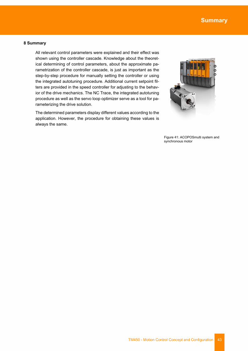
All relevant control parameters were explained and their effect wasshown using the controller cascade. Knowledge about the theoret-ical determining of control parameters, about the approximate pa-rametrization of the controller cascade, is just as important as thestep-by-step procedure for manually setting the controller or usingthe integrated autotuning procedure. Additional current setpoint fil-ters are provided in the speed controller for adjusting to the behav-ior of the drive mechanics. The NC Trace, the integrated autotuningprocedure as well as the servo loop optimizer serve as a tool for pa-rameterizing the drive solution.
The determined parameters display different values according to theapplication. However, the procedure for obtaining these values isalways the same.
Figure 41: ACOPOSmulti system andsynchronous motor

Offered by the Automation Academy
44 TM450 - Motion Control Concept and Configuration
Offered by the Automation Academy
The Automation Academy provides targeted training courses for our customers as well as our own em-ployees.At the Automation Academy, you'll develop the skills you need in no time!Our seminars make it possible for you to improve your knowledge in the field of automation engineering.Once completed, you will be in a position to implement efficient automation solutions using B&R technol-ogy. This will make it possible for you to secure a decisive competitive edge by allowing you and yourcompany to react faster to constantly changing market demands.
Seminars
Quality and relevance are essential components of our seminars. Thepace of a specific seminar is based strictly on the experience that courseparticipants bring with them and tailored to the requirements they face. Acombination of group work and self-study provides the high level of flexi-bility needed to maximize the learning experience.Each seminar is taught by one of our highly skilled and experiencedtrainers.
Training modules
Our training modules provide the basis for learning both at seminarsas well as for self-study. These compact modules rely on a consistentdidactic concept. Their bottom-up structure allows complex, interre-lated topics to be learned efficiently and effectively. They serve asthe best possible companion to our extensive help system. The train-ing modules are available as downloads and can be ordered as print-ed versions.
Topic categories:➯ Control technology➯ Motion control➯ Safety technology➯ HMI➯ Process control➯ Diagnostics and service➯ POWERLINK and openSAFETY
ETA system
The ETA system provides realistic constructions for training, educationand laboratory use. Two different basic mechanical constructions can beselected. The ETA light system offers a high degree of mobility, savesspace and is well-suited for lab work. The ETA standard system has asturdy mechanical structure and includes pre-wired sensors and actua-tors.
Find out more!
Do you require additional training? Are you interested in finding out what the B&RAutomation Academy has on offer? You've come to the right place.Detailed information can be found under the following links:www.br-automation.com/academy

Offered by the Automation Academy
TM450 - Motion Control Concept and Configuration 45

Offered by the Automation Academy
46 TM450 - Motion Control Concept and Configuration

Offered by the Automation Academy
TM450 - Motion Control Concept and Configuration 47

V1.1
.0.1
©20
17/0
9/21
by
B&R
, All
right
s re
serv
ed.
All r
egis
tere
d tra
dem
arks
are
the
prop
erty
of t
heir
resp
ectiv
e ow
ners
.W
e re
serv
e th
e rig
ht to
mak
e te
chni
cal c
hang
es.