Embed Size (px)
Citation preview

Yamaha Router Configuration Training
~ Web GUI ~

© Yamaha Corporation 2
Equipment
RTX810 SWX2200-8G/24G
GbE ×5, USB 3G modem 1Gbps throughput
200Mbps VPN throughput
IPv6 ready
Withstand up to 50℃
All GbE Cooperation with RTX810
Gigabit VPN Router Smart L2 Switch

© Yamaha Corporation 3
Contents
Web GUI operation PPPoE IPsec VPN SWX2200 Control
• Loop Detect •Search Host •VLAN

© Yamaha Corporation
Before training
4
Please disable Windows firewall.
[Start menu] – [Control Panel] – [Windows Firewall] Select “Turn Windows Firewall on or off”.

© Yamaha Corporation 5
Access into the Router
192.168.100.1 RTX810 Web browser
http://192.168.100.1/
Username : blank Password : Admin Password ※ If the Admin password is not set, You will keep form blank.
© Yamaha Corporation 6
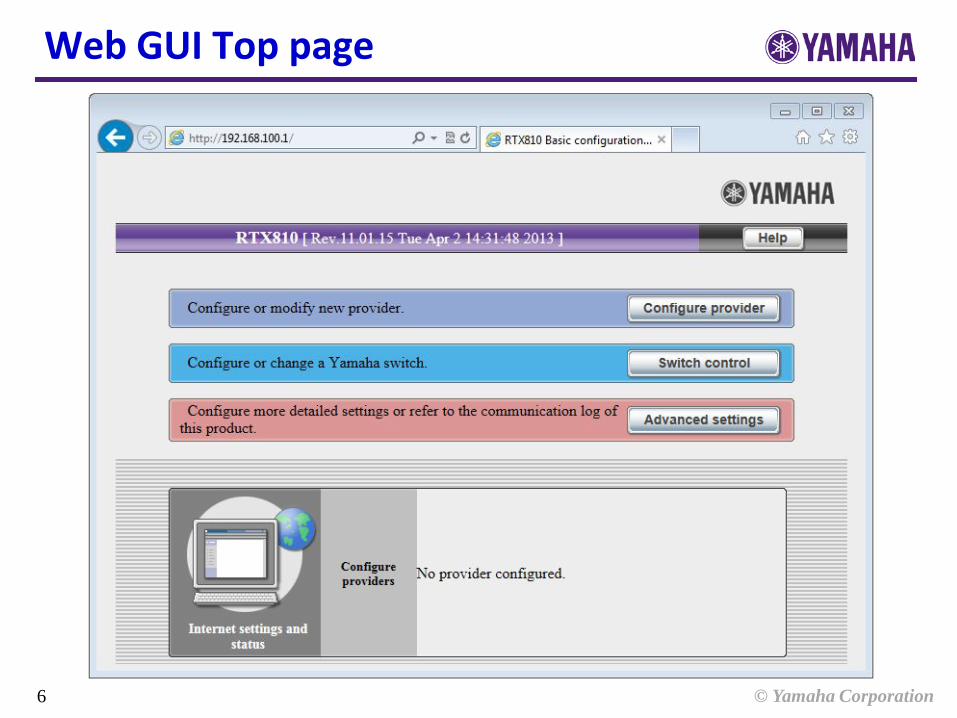
Web GUI Top page

© Yamaha Corporation 7
Internet Accessing (PPPoE)
192.168.100.0/24
.1 (LAN)
Internet
■Configure PPPoE Setting for Internet Access
(WAN)
PC

© Yamaha Corporation 8
1. PPPoE (1)
Select [Configure provider].

© Yamaha Corporation 9
1. PPPoE (2)
The router detects the type of line automatically. Click [Next].

© Yamaha Corporation 10
1. PPPoE (3)
“ PPPoE ” is selected. Click [Next].

© Yamaha Corporation 11
1. PPPoE (4)
Fill the form with User ID and Connect password. Click [Next].
Router-A ID: user1, PASS: pass1 Router-B ID: user2, PASS: pass2

© Yamaha Corporation 12
1. PPPoE (5)
Select “ not specify DNS ” Click [Next].
※ If the provider assigned DNS server address, you will select another radio button and fill the form with address.

© Yamaha Corporation 13
1. PPPoE (6)
Check the Information that you selected and filled. Click [Submit].

© Yamaha Corporation 14
1. PPPoE (7)
Provider registration is completed and click [Connect].

© Yamaha Corporation 15
Top page view after PPPoE setting

© Yamaha Corporation 16
2. Check configuration (1)
Select [Advanced settings].

© Yamaha Corporation 17
2. Check configuration (2)
Select “ all configurations ”.

© Yamaha Corporation 18
2. Check configuration (3)
Click “ View in text format ” to show configuration as console format.

© Yamaha Corporation 19
2. Check configuration (4) Routing Configuration
PPPoE Configuration
Interface addressing Configuration

© Yamaha Corporation 20
2. Check configuration (5)
Static Filter Configuration

© Yamaha Corporation 21
2. Check configuration (6)
Dynamic Filter Configuration
NAT, DHCP, DNS Configuration

© Yamaha Corporation 22
Close the configuration page. Click “ Return to top ” at the bottom of the page.
2. Check configuration (7)

© Yamaha Corporation 23
IPsec VPN (Main Mode)
172.16.1.0/24
Internet (200.1.1.0/24)
IPSec
Router-B
.202 .201
.1 .1
■Configure IPsec VPN (Main Mode) via Internet
172.16.2.0/24
Router-A
PSK: secret PSK: secret
PC2 PC1
1st step: Configure LAN setting 2nd step: Configure IPsec VPN

© Yamaha Corporation 24
3. LAN interface addressing (1)
Click [Advanced settings].

© Yamaha Corporation 25
3. LAN interface addressing (2)
Click [Configure LAN].

© Yamaha Corporation 26
3. LAN interface addressing (3)
Fill with LAN interface IP address. Router-A 172.16.1.1 Router-B 172.16.2.1
Fill with DHCP scope ID and IP address range. Router-A 172.16.1.2 - 172.16.1.191 Router-B 172.16.2.2 – 172.16.2.191

© Yamaha Corporation 27
3. LAN interface addressing (3)
Check the parameters are correct.
Click [Execute].

© Yamaha Corporation 28
3. LAN interface addressing (3)
LAN interface IP address and DHCP scope exchange is completed. Pull out the cable of PC and wait for 10 seconds for refresh the PC’s address. Connect the cable to PC. Click “ Access the new IP address via http ”.

© Yamaha Corporation 29
4. IPsec VPN (1)
Select [Advanced settings].
© Yamaha Corporation 30
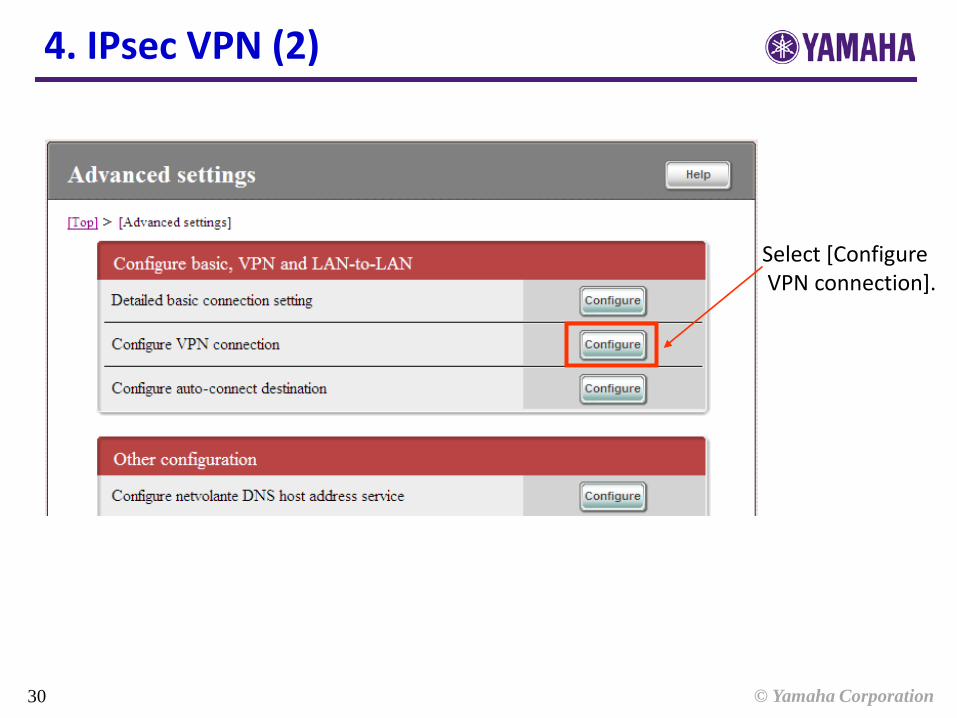
4. IPsec VPN (2)
Select [Configure VPN connection].

© Yamaha Corporation 31
4. IPsec VPN (3)
Select [Add] on “ Tunnel[01] ”.

© Yamaha Corporation 32
4. IPsec VPN (4)
Select “ LAN-to-LAN network over IPsec ”. Click [Next].

© Yamaha Corporation 33
4. IPsec VPN (5)
Router A 200.1.1.202 Router B 200.1.1.201
Fill with pre-shared-key. Select “ Identify using IP address ” and fill with opposite router address. Select Authentication and Encryption algorithm. ※ Select same as opposite. Select keepalive use or not.
“ secret ”
© Yamaha Corporation 34
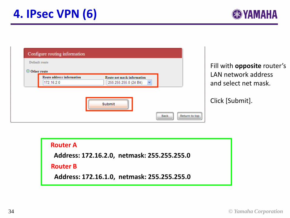
4. IPsec VPN (6)
Fill with opposite router’s LAN network address and select net mask. Click [Submit].
Router A Address: 172.16.2.0, netmask: 255.255.255.0 Router B Address: 172.16.1.0, netmask: 255.255.255.0

© Yamaha Corporation 35
4. IPsec VPN (7)
IPsec registration is completed and click [Return to top].

© Yamaha Corporation 36
Top page view after IPsec setting

© Yamaha Corporation 37
4. IPsec VPN (8)
172.16.1.0/24
Internet (200.1.1.0/24)
IPSec
Router-B
.202 .201
.1 .1
172.16.2.0/24
Router-A
PSK: secret PSK: secret
PC2 PC1
Ping is available between PC1 and PC2
172.16.1.2 172.16.2.2

© Yamaha Corporation 38
4. Configuration (1)
Routing Configuration
PPPoE Configuration
Added Interface addressing configuration

© Yamaha Corporation 39
4. Configuration (2)
IPsec VPN Configuration
Static Filter Configuration

© Yamaha Corporation 40
4. Configuration (3)
Static Filter Configuration
Dynamic Filter Configuration
NAT, DHCP, DNS Configuration
Added
Added
© Yamaha Corporation 41
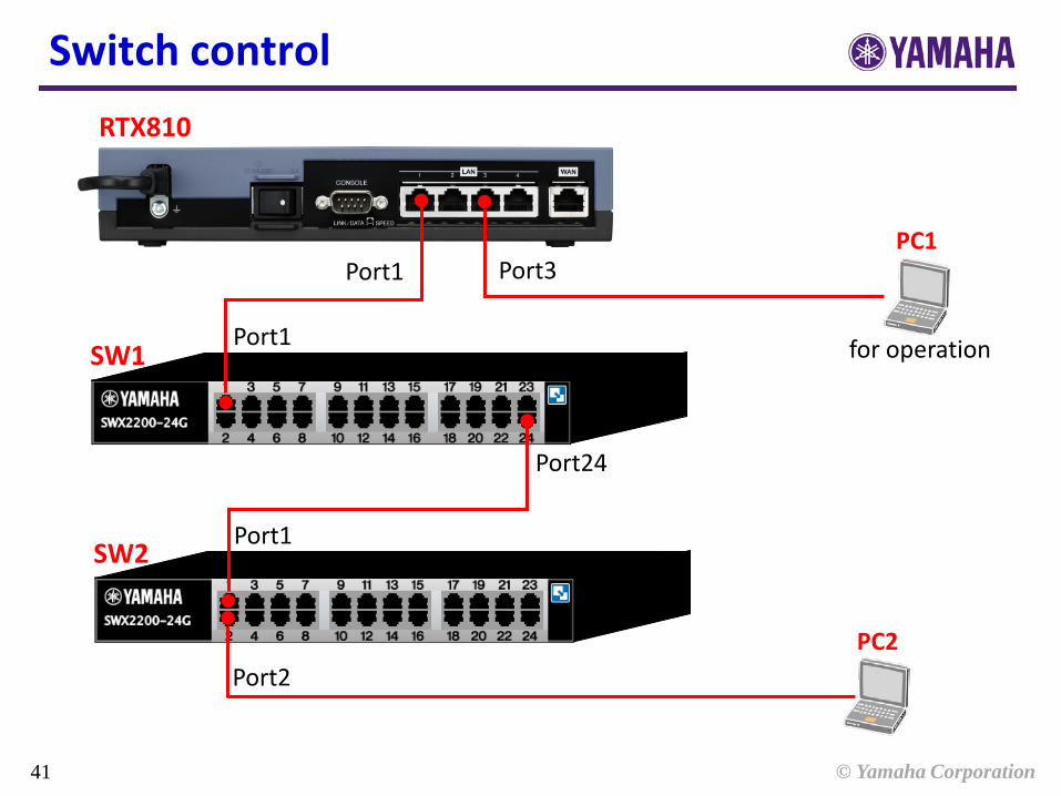
Switch control
Port1
Port1
Port3
Port24
Port1
Port2
SW1
SW2
RTX810
PC1
PC2
for operation
© Yamaha Corporation 42
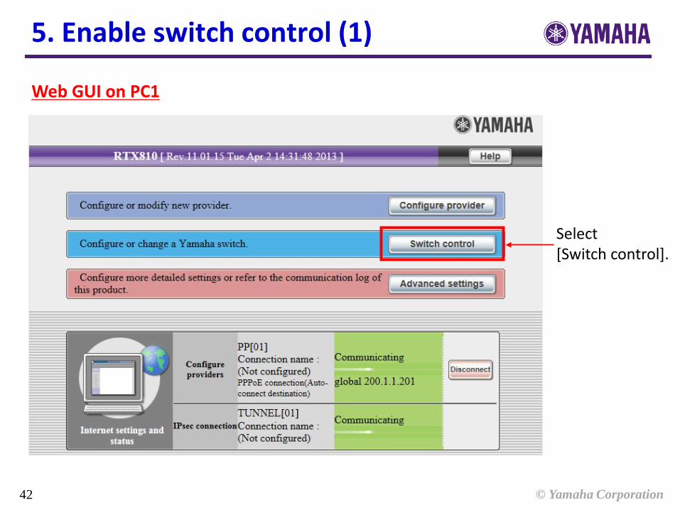
5. Enable switch control (1)
Web GUI on PC1
Select [Switch control].

© Yamaha Corporation 43
5. Enable switch control (2)
Select [Basic configuration].
© Yamaha Corporation 44
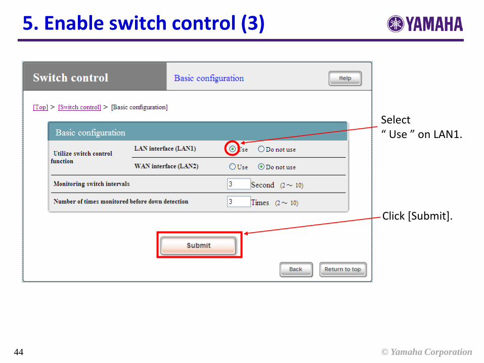
5. Enable switch control (3)
Select “ Use ” on LAN1.
Click [Submit].

© Yamaha Corporation 45
5. Enable switch control (4)
Configure completed. Click [Return to top].

© Yamaha Corporation 46
5. Open switch control GUI (1)
Web GUI on PC1
Select [Switch control].
© Yamaha Corporation 47
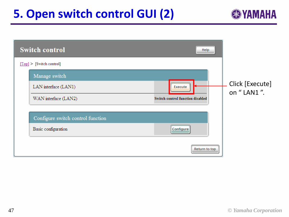
5. Open switch control GUI (2)
Click [Execute] on “ LAN1 ”.

© Yamaha Corporation 48
6. Switch control GUI (1)
Click “ View in detail all devices ”, you will see the detail of switch and each port information.

© Yamaha Corporation 49
6. Switch control GUI (2)
Move pointer onto the switch body and each port. The brief information will be displayed.
© Yamaha Corporation 50
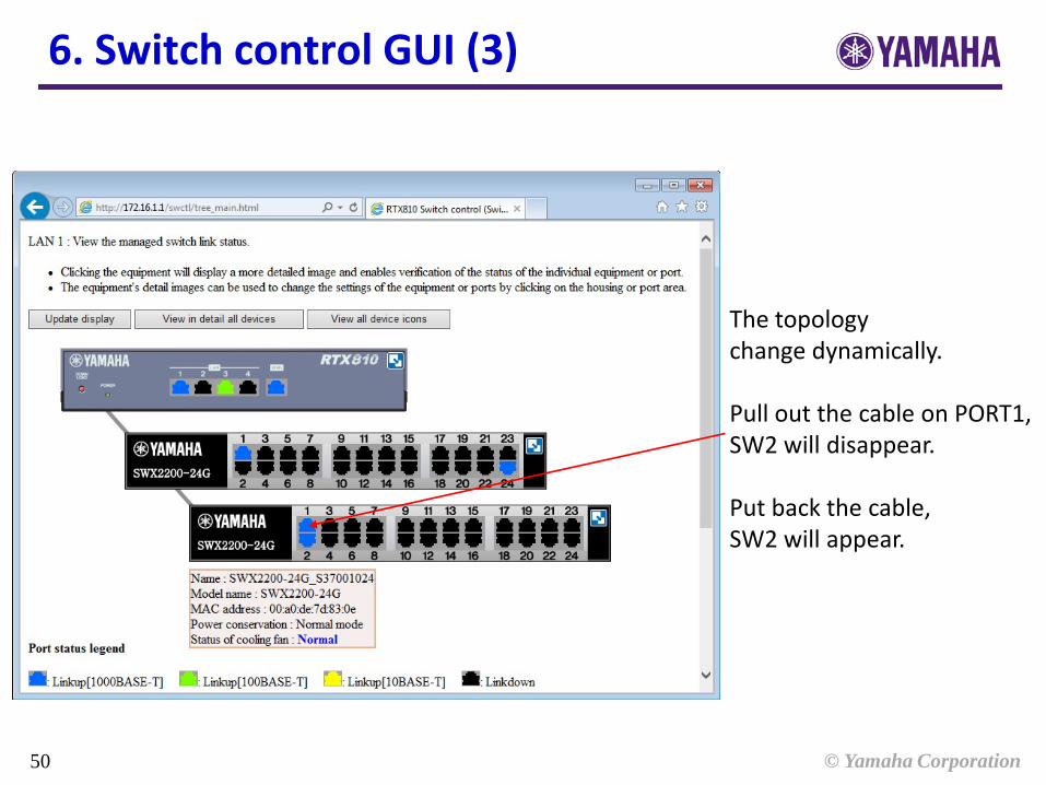
6. Switch control GUI (3)
The topology change dynamically. Pull out the cable on PORT1, SW2 will disappear. Put back the cable, SW2 will appear.

© Yamaha Corporation 51
SW
RTX810
Router sends a proprietary mac frames for switch control regularly to find connected switches. In default: interval time is 3seconds. This frame is used to configure and get status of switches also.
6. Switch control GUI (4)
Switch control mechanism

© Yamaha Corporation 52
6. Switch control GUI (5)
Click the switch’s body: Enable to configure follow: - Name - Firmware update - Power conservation - Loop detection - Port mirroring - Reset frame counter - Restart - Factory default
Configure the switch

© Yamaha Corporation 53
6. Switch control GUI (6)
Click the switch’s port: Enable to configure follow: - Auto negotiation - Speed - Flow control - QoS - Tag VLAN - Multiple VLAN - Frame counter
Configure the ports

© Yamaha Corporation 54
7. Loop detect configuration (1)
Click SW2’s body.
© Yamaha Corporation 55
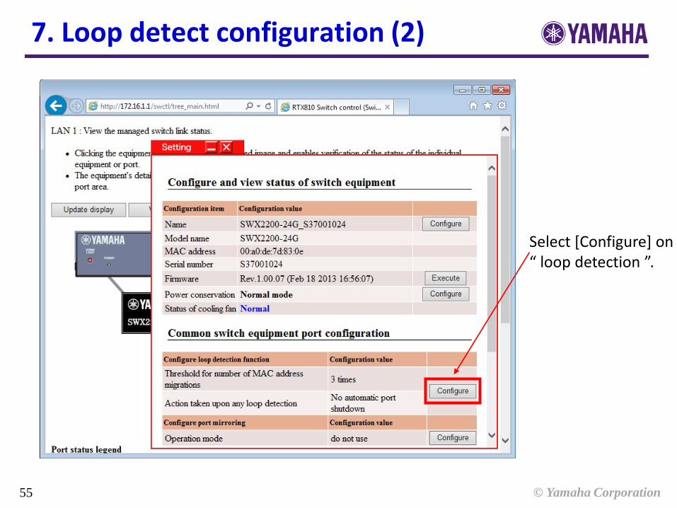
7. Loop detect configuration (2)
Select [Configure] on “ loop detection ”.

© Yamaha Corporation 56
7. Loop detect configuration (3)
Select “ Automatically shutdown ” and set 300 seconds as port shutdown time. Click [Configure].
※ By default, if the packet loop happened, the switch does not shutdown the loop detected port. The packet loop will remain.

© Yamaha Corporation 57
7. Loop detect configuration (4)
Port1
Port1
Port3
Port24
Port1
SW1
SW2
RTX810
PC1
Make a loop case.

© Yamaha Corporation 58
7. Loop detect configuration (5)
Exclamation mark is displayed on the loop detected port. The switch shutdown the port from bigger number until the packet loop stop. Port shutdown last in 300 seconds. After 300 seconds or pushing MODE button on the front panel, the port will recover from shutdown.

© Yamaha Corporation 59
8. Host search (1)
The function to search a host which connected to switch from an IP address or MAC address.
Click [Search for host].

© Yamaha Corporation 60
8. Host search (2)
DHCP client list and ARP entry list are displayed. Fill the form with PC2’s IP or MAC address. Click [Search].

© Yamaha Corporation 61
8. Host search (3)
The host detected port will blink.

© Yamaha Corporation 62
Tagged and Untagged 172.16.1.0/24 (VID : -) 192.168.100.0/24 (VID : 101)
Untagged 172.16.1.0/24
Untagged 192.168.100.0/24
9. VLAN
Port1
Port1
Port3
Port24
Port1
Port2
SW1
SW2
RTX810
PC1
PC2
192.168.100.2
172.16.1.2
LAN1 : 172.16.1.1/24 LAN1/1 : 192.168.100.0/24

© Yamaha Corporation 63
9. VLAN (1)
Select “ Create new VLAN tag ”.
Switch control GUI on PC1

© Yamaha Corporation 64
9. VLAN (2)
Click router icon.
© Yamaha Corporation 65
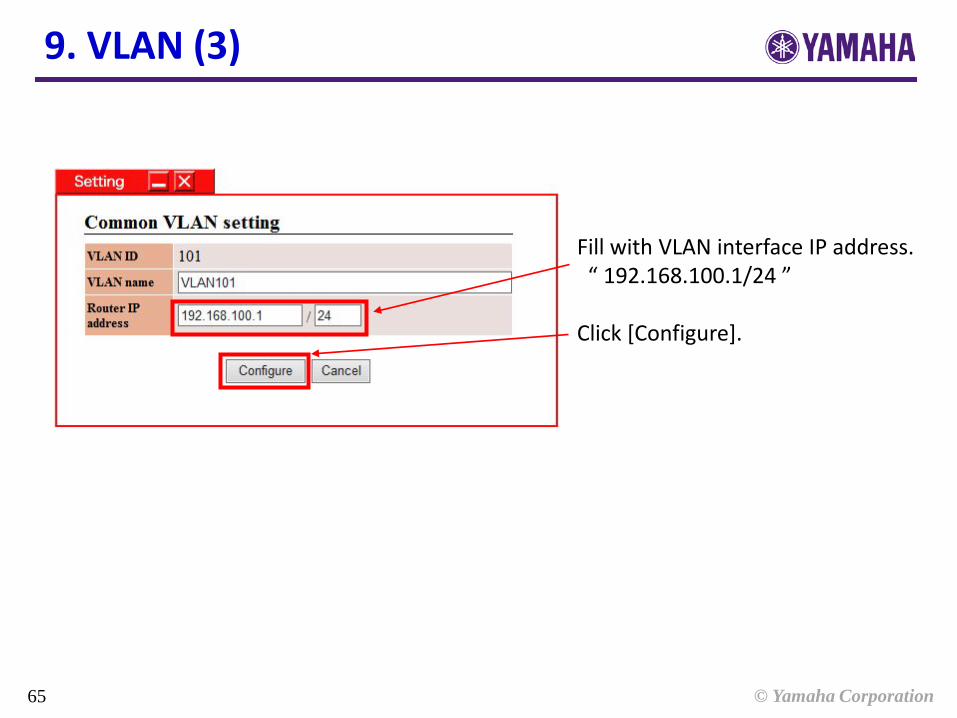
9. VLAN (3)
Fill with VLAN interface IP address. “ 192.168.100.1/24 ” Click [Configure].

© Yamaha Corporation 66
9. VLAN (4)
Click the port that connected with PC2. All ports routing from the router to the selected port is automatically configured as same VLAN group. Click [Configure] at the bottom of the page.

© Yamaha Corporation 67
9. VLAN (5)
VLAN interface IP address is set to 192.168.100.1/24 The switch joined VLAN is encircled by blue line. Click [back] at the bottom of page.

© Yamaha Corporation 68
9. VLAN (6)
Ping is available between PC1 and PC2 by routing the different network segments. It is also possible to make filtering for each VLAN network.
Port1
Port1
Port3
Port24
Port1
Port2
SW1
SW2
RTX810
PC1
PC2
192.168.100.2
172.16.1.2

© Yamaha Corporation 69
9. Configuration
① Enable switch control
② VLAN configuration
③ SW1 configuration
④ SW2 configuration
//① //②
//③
//④
・・・ 192.168.100.1/24

© Yamaha Corporation 70 70
Continue to console operation