Embed Size (px)
Citation preview
Configure the Cisco Fabric Border Provider Edge Feature for VXLAN EVPN FabricWhite PaperCisco Public
© 2016 Cisco and/or its affiliates. All rights reserved.
Configure the Cisco Fabric Border Provider Edge Feature for VXLAN EVPN Fabric
Configure the Cisco Fabric Border Provider Edge Feature for VXLAN EVPN FabricWhite PaperCisco Public
© 2016 Cisco and/or its affiliates. All rights reserved.
Contents page
What You Will Learn 3
Prerequisites 3
Introduction 3
Hardware and Software Requirements 4VXLAN EVPN BorderPE Requirements 4
Fabric and MPLS Network Requirements 4
VXLAN EVPN BorderPE Deployment Details 4Physical Overview 4
BorderPE Forwarding Details 5Forwarding from the Fabric to the MPLS Network 5
Forwarding from the MPLS Network to the Fabric 7
Configuration Example 8
Conclusion 9
Configure the Cisco Fabric Border Provider Edge Feature for VXLAN EVPN FabricWhite PaperCisco Public
© 2016 Cisco and/or its affiliates. All rights reserved.
What You Will LearnThis document describes how to integrate Virtual Extensible LAN (VXLAN) Ethernet Virtual Private Network (EVPN) fabric with Multiprotocol Label Switching (MPLS) Layer 3 VPN (L3VPN) using the Cisco® Fabric Border Provider Edge (BorderPE) feature. It also provides a configuration example to demonstrate the process.
The VXLAN EVPN fabric can be connected across Layer 3 boundaries using MPLS L3VPN, Virtual Routing and Forwarding (VRF) IP routing (VRF-lite), or Cisco Locator/ID Separation Protocol (LISP). This document focused on Layer 3 fabric connectivity using MPLS L3VPN.
For information about connecting VXLAN EVPN fabric with LISP for Layer 3 connectivity, please refer the following white paper: http://www.cisco.com/c/en/us/products/collateral/switches/nexus-7000-series-switches/white-paper-c11-734843.html.
PrerequisitesThis document assumes that the reader is already familiar with the configuration of VXLAN EVPN data center fabric. The VXLAN EVPN fabric can be configured either manually or using Cisco Data Center Network Manager (DCNM) for the underlay and Cisco Virtual Topology System (VTS) for the overlay. This document focuses entirely on providing external Layer 3 connectivity to the fabric with the assumption that the data center fabric is already configured and working on all devices, including the border leaf and spine nodes.
For more information about VXLAN EVPN, including examples showing configuration details, please refer the following white paper: http://www.cisco.com/c/en/us/products/collateral/switches/nexus-7000-series-switches/white-paper-c11-735015.html.
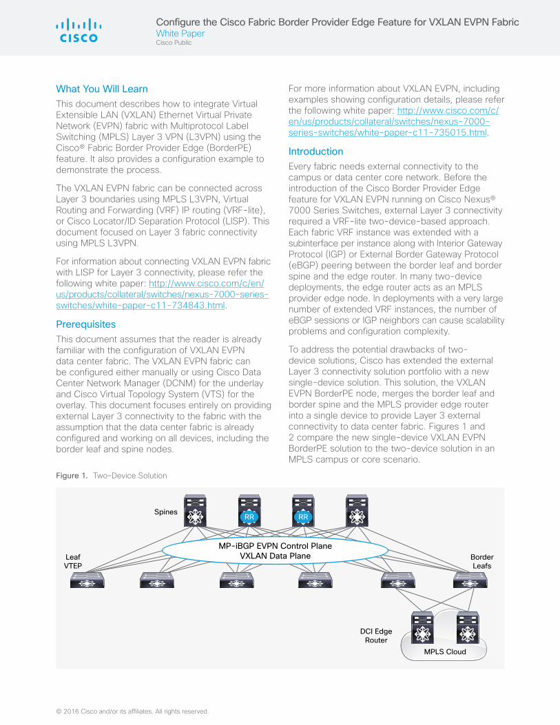
IntroductionEvery fabric needs external connectivity to the campus or data center core network. Before the introduction of the Cisco Border Provider Edge feature for VXLAN EVPN running on Cisco Nexus® 7000 Series Switches, external Layer 3 connectivity required a VRF-lite two-device-based approach. Each fabric VRF instance was extended with a subinterface per instance along with Interior Gateway Protocol (IGP) or External Border Gateway Protocol (eBGP) peering between the border leaf and border spine and the edge router. In many two-device deployments, the edge router acts as an MPLS provider edge node. In deployments with a very large number of extended VRF instances, the number of eBGP sessions or IGP neighbors can cause scalability problems and configuration complexity.
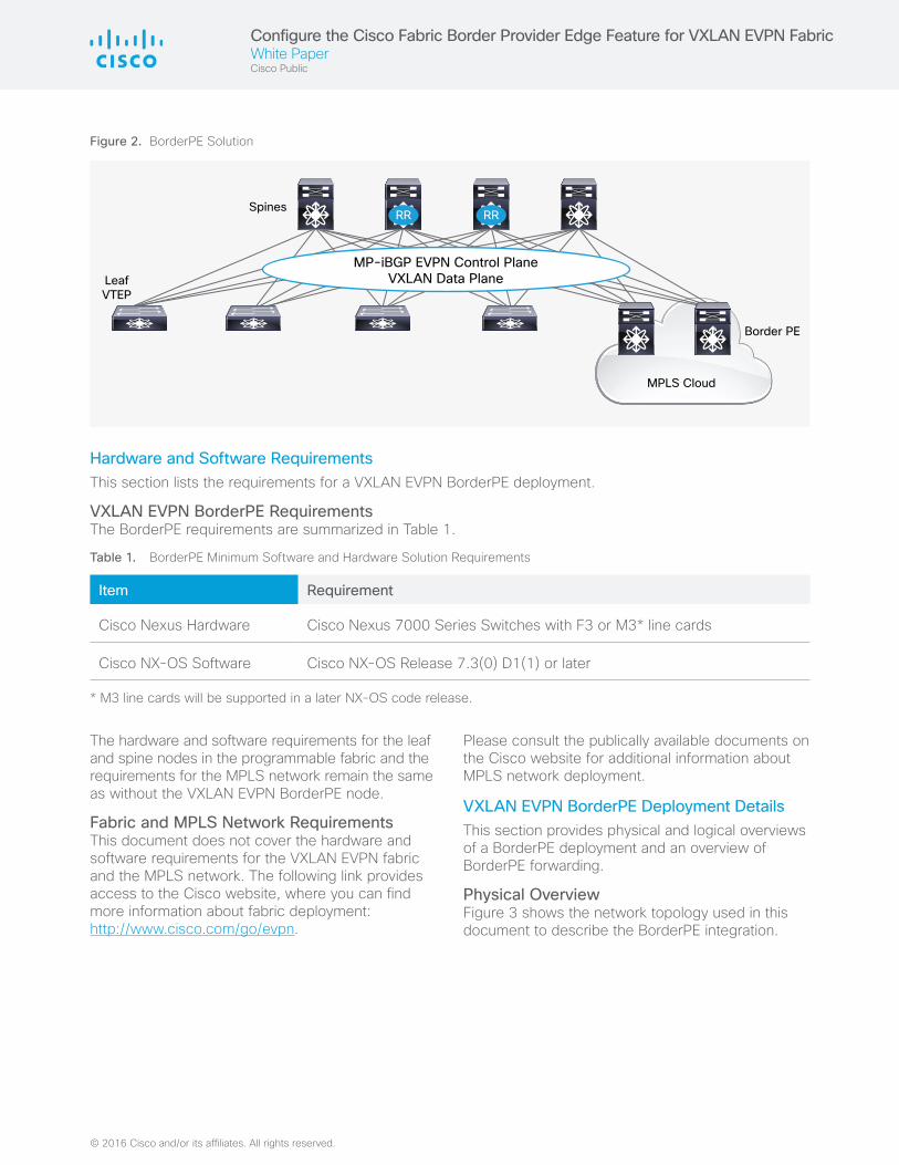
To address the potential drawbacks of two-device solutions, Cisco has extended the external Layer 3 connectivity solution portfolio with a new single-device solution. This solution, the VXLAN EVPN BorderPE node, merges the border leaf and border spine and the MPLS provider edge router into a single device to provide Layer 3 external connectivity to data center fabric. Figures 1 and 2 compare the new single-device VXLAN EVPN BorderPE solution to the two-device solution in an MPLS campus or core scenario.
MPLS Cloud
DCI EdgeRouter
BorderLeafs
LeafVTEP
SpinesRR RR
MP-iBGP EVPN Control PlaneVXLAN Data Plane
Figure 1. Two-Device Solution
Configure the Cisco Fabric Border Provider Edge Feature for VXLAN EVPN FabricWhite PaperCisco Public
© 2016 Cisco and/or its affiliates. All rights reserved.
Hardware and Software Requirements This section lists the requirements for a VXLAN EVPN BorderPE deployment.
VXLAN EVPN BorderPE Requirements The BorderPE requirements are summarized in Table 1.
Table 1. BorderPE Minimum Software and Hardware Solution Requirements
Item Requirement
Cisco Nexus Hardware Cisco Nexus 7000 Series Switches with F3 or M3* line cards
Cisco NX-OS Software Cisco NX-OS Release 7.3(0) D1(1) or later
* M3 line cards will be supported in a later NX-OS code release.
The hardware and software requirements for the leaf and spine nodes in the programmable fabric and the requirements for the MPLS network remain the same as without the VXLAN EVPN BorderPE node.
Fabric and MPLS Network Requirements This document does not cover the hardware and software requirements for the VXLAN EVPN fabric and the MPLS network. The following link provides access to the Cisco website, where you can find more information about fabric deployment: http://www.cisco.com/go/evpn.
Please consult the publically available documents on the Cisco website for additional information about MPLS network deployment.
VXLAN EVPN BorderPE Deployment DetailsThis section provides physical and logical overviews of a BorderPE deployment and an overview of BorderPE forwarding.
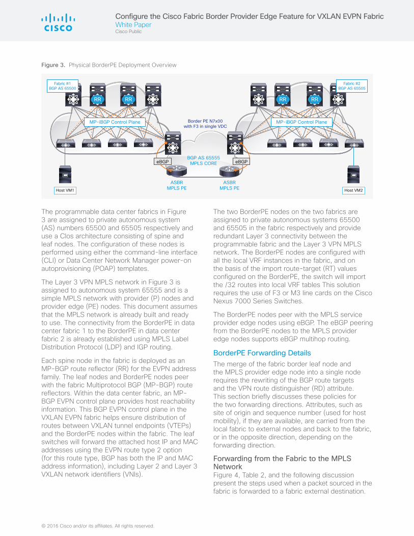
Physical OverviewFigure 3 shows the network topology used in this document to describe the BorderPE integration.
Figure 2. BorderPE Solution
MPLS Cloud
Border PE
LeafVTEP
SpinesRR RR
MP-iBGP EVPN Control PlaneVXLAN Data Plane
Configure the Cisco Fabric Border Provider Edge Feature for VXLAN EVPN FabricWhite PaperCisco Public
© 2016 Cisco and/or its affiliates. All rights reserved.
The programmable data center fabrics in Figure 3 are assigned to private autonomous system (AS) numbers 65500 and 65505 respectively and use a Clos architecture consisting of spine and leaf nodes. The configuration of these nodes is performed using either the command-line interface (CLI) or Data Center Network Manager power-on autoprovisioning (POAP) templates.
The Layer 3 VPN MPLS network in Figure 3 is assigned to autonomous system 65555 and is a simple MPLS network with provider (P) nodes and provider edge (PE) nodes. This document assumes that the MPLS network is already built and ready to use. The connectivity from the BorderPE in data center fabric 1 to the BorderPE in data center fabric 2 is already established using MPLS Label Distribution Protocol (LDP) and IGP routing.
Each spine node in the fabric is deployed as an MP-BGP route reflector (RR) for the EVPN address family. The leaf nodes and BorderPE nodes peer with the fabric Multiprotocol BGP (MP-BGP) route reflectors. Within the data center fabric, an MP-BGP EVPN control plane provides host reachability information. This BGP EVPN control plane in the VXLAN EVPN fabric helps ensure distribution of routes between VXLAN tunnel endpoints (VTEPs) and the BorderPE nodes within the fabric. The leaf switches will forward the attached host IP and MAC addresses using the EVPN route type 2 option (for this route type, BGP has both the IP and MAC address information), including Layer 2 and Layer 3 VXLAN network identifiers (VNIs).
The two BorderPE nodes on the two fabrics are assigned to private autonomous systems 65500 and 65505 in the fabric respectively and provide redundant Layer 3 connectivity between the programmable fabric and the Layer 3 VPN MPLS network. The BorderPE nodes are configured with all the local VRF instances in the fabric, and on the basis of the import route-target (RT) values configured on the BorderPE, the switch will import the /32 routes into local VRF tables This solution requires the use of F3 or M3 line cards on the Cisco Nexus 7000 Series Switches.
The BorderPE nodes peer with the MPLS service provider edge nodes using eBGP. The eBGP peering from the BorderPE nodes to the MPLS provider edge nodes supports eBGP multihop routing.
BorderPE Forwarding Details The merge of the fabric border leaf node and the MPLS provider edge node into a single node requires the rewriting of the BGP route targets and the VPN route distinguisher (RD) attribute. This section briefly discusses these policies for the two forwarding directions. Attributes, such as site of origin and sequence number (used for host mobility), if they are available, are carried from the local fabric to external nodes and back to the fabric, or in the opposite direction, depending on the forwarding direction.
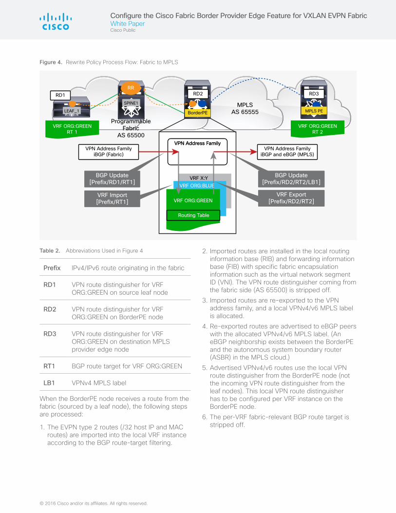
Forwarding from the Fabric to the MPLS Network Figure 4, Table 2, and the following discussion present the steps used when a packet sourced in the fabric is forwarded to a fabric external destination.
Host VM2Host VM1
BGP AS 65555MPLS CORE
Border PE N7x00with F3 in single VDC
ASBRMPLS PE
ASBRMPLS PE
Fabric #1BGP AS 65500
Fabric #2BGP AS 65505
MP-iBGP Control Plane
eBGPeBGP
MP-iBGP Control Plane
RR RR RR RR
Figure 3. Physical BorderPE Deployment Overview
Configure the Cisco Fabric Border Provider Edge Feature for VXLAN EVPN FabricWhite PaperCisco Public
© 2016 Cisco and/or its affiliates. All rights reserved.
Table 2. Abbreviations Used in Figure 4
Prefix IPv4/IPv6 route originating in the fabric
RD1 VPN route distinguisher for VRF ORG:GREEN on source leaf node
RD2 VPN route distinguisher for VRF ORG:GREEN on BorderPE node
RD3 VPN route distinguisher for VRF ORG:GREEN on destination MPLS provider edge node
RT1 BGP route target for VRF ORG:GREEN
LB1 VPNv4 MPLS label
When the BorderPE node receives a route from the fabric (sourced by a leaf node), the following steps are processed:
1. The EVPN type 2 routes (/32 host IP and MAC routes) are imported into the local VRF instance according to the BGP route-target filtering.
2. Imported routes are installed in the local routing information base (RIB) and forwarding information base (FIB) with specific fabric encapsulation information such as the virtual network segment ID (VNI). The VPN route distinguisher coming from the fabric side (AS 65500) is stripped off.
3. Imported routes are re-exported to the VPN address family, and a local VPNv4/v6 MPLS label is allocated.
4. Re-exported routes are advertised to eBGP peers with the allocated VPNv4/v6 MPLS label. (An eBGP neighborship exists between the BorderPE and the autonomous system boundary router (ASBR) in the MPLS cloud.)
5. Advertised VPNv4/v6 routes use the local VPN route distinguisher from the BorderPE node (not the incoming VPN route distinguisher from the leaf nodes). This local VPN route distinguisher has to be configured per VRF instance on the BorderPE node.
6. The per-VRF fabric-relevant BGP route target is stripped off.
RD3
LEAF_1
SPINE1
RD1
MPLSAS 65555
ProgrammableFabric
AS 65500
VRF ORG:GREENRT 1
VRF ORG:GREENRT 2
VRF ORG:GREEN
VRF X:Y
Routing Table
VPN Address FamilyiBGP (Fabric)
VPN Address FamilyiBGP and eBGP (MPLS)
BGP Update[Prefix/RD2/RT2/LB1]
BGP Update[Prefix/RD1/RT1]
VRF Import[Prefix/RT1]
VRF Export[Prefix/RD2/RT2]
VPN Address FamilyVPN Address Family
RR
MPLS PE
VRF ORG:BLUE
RD2
BorderPE
Figure 4. Rewrite Policy Process Flow: Fabric to MPLS
Configure the Cisco Fabric Border Provider Edge Feature for VXLAN EVPN FabricWhite PaperCisco Public
© 2016 Cisco and/or its affiliates. All rights reserved.
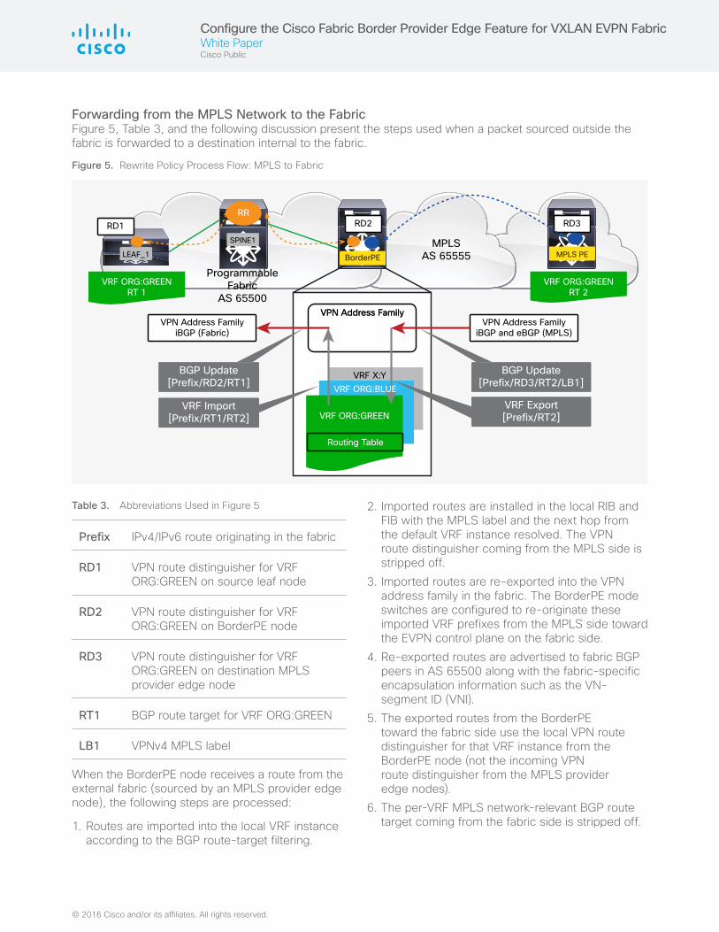
Forwarding from the MPLS Network to the Fabric Figure 5, Table 3, and the following discussion present the steps used when a packet sourced outside the fabric is forwarded to a destination internal to the fabric.
Figure 5. Rewrite Policy Process Flow: MPLS to Fabric
RD3RD2
LEAF_1
SPINE1
RD1
MPLSAS 65555
ProgrammableFabric
AS 65500
VRF ORG:GREENRT 1
VRF ORG:GREENRT 2
VRF ORG:GREEN
VRF X:Y
Routing Table
VPN Address FamilyiBGP (Fabric)
VPN Address FamilyiBGP and eBGP (MPLS)
BGP Update[Prefix/RD3/RT2/LB1]
BGP Update[Prefix/RD2/RT1]
VRF Import[Prefix/RT1/RT2]
VRF Export[Prefix/RT2]
VPN Address FamilyVPN Address Family
RR
BorderPE MPLS PE
VRF ORG:BLUE
Table 3. Abbreviations Used in Figure 5
Prefix IPv4/IPv6 route originating in the fabric
RD1 VPN route distinguisher for VRF ORG:GREEN on source leaf node
RD2 VPN route distinguisher for VRF ORG:GREEN on BorderPE node
RD3 VPN route distinguisher for VRF ORG:GREEN on destination MPLS provider edge node
RT1 BGP route target for VRF ORG:GREEN
LB1 VPNv4 MPLS label
When the BorderPE node receives a route from the external fabric (sourced by an MPLS provider edge node), the following steps are processed:
1. Routes are imported into the local VRF instance according to the BGP route-target filtering.
2. Imported routes are installed in the local RIB and FIB with the MPLS label and the next hop from the default VRF instance resolved. The VPN route distinguisher coming from the MPLS side is stripped off.
3. Imported routes are re-exported into the VPN address family in the fabric. The BorderPE mode switches are configured to re-originate these imported VRF prefixes from the MPLS side toward the EVPN control plane on the fabric side.
4. Re-exported routes are advertised to fabric BGP peers in AS 65500 along with the fabric-specific encapsulation information such as the VN-segment ID (VNI).
5. The exported routes from the BorderPE toward the fabric side use the local VPN route distinguisher for that VRF instance from the BorderPE node (not the incoming VPN route distinguisher from the MPLS provider edge nodes).
6. The per-VRF MPLS network-relevant BGP route target coming from the fabric side is stripped off.
Configure the Cisco Fabric Border Provider Edge Feature for VXLAN EVPN FabricWhite PaperCisco Public
© 2016 Cisco and/or its affiliates. All rights reserved.
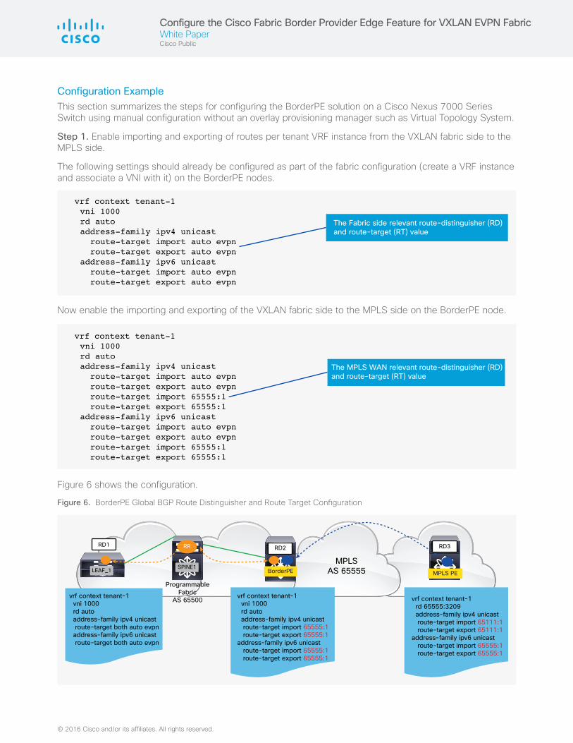
Configuration Example This section summarizes the steps for configuring the BorderPE solution on a Cisco Nexus 7000 Series Switch using manual configuration without an overlay provisioning manager such as Virtual Topology System.
Step 1. Enable importing and exporting of routes per tenant VRF instance from the VXLAN fabric side to the MPLS side.
The following settings should already be configured as part of the fabric configuration (create a VRF instance and associate a VNI with it) on the BorderPE nodes.
The Fabric side relevant route-distinguisher (RD) and route-target (RT) value
vrf context tenant-1 vni 1000 rd auto address-family ipv4 unicast route-target import auto evpn route-target export auto evpn address-family ipv6 unicast route-target import auto evpn route-target export auto evpn
Now enable the importing and exporting of the VXLAN fabric side to the MPLS side on the BorderPE node.
The MPLS WAN relevant route-distinguisher (RD) and route-target (RT) value
vrf context tenant-1 vni 1000 rd auto address-family ipv4 unicast route-target import auto evpn route-target export auto evpn route-target import 65555:1 route-target export 65555:1 address-family ipv6 unicast route-target import auto evpn route-target export auto evpn route-target import 65555:1 route-target export 65555:1
Figure 6 shows the configuration.
Figure 6. BorderPE Global BGP Route Distinguisher and Route Target Configuration
MPLS PEBorderPEMPLS
AS 65555Programmable
FabricAS 65500
vrf context tenant-1 vni 1000 rd auto address-family ipv4 unicast route-target both auto evpn address-family ipv6 unicast route-target both auto evpn
vrf context tenant-1 vni 1000 rd auto address-family ipv4 unicast route-target import 65555:1 route-target export 65555:1address-family ipv6 unicast route-target import 65555:1 route-target export 65555:1
RR
vrf context tenant-1 rd 65555:3209 address-family ipv4 unicast route-target import 65111:1 route-target export 65111:1address-family ipv6 unicast route-target import 65555:1 route-target export 65555:1
RD3RD2RD1
LEAF_1 SPINE1
Configure the Cisco Fabric Border Provider Edge Feature for VXLAN EVPN FabricWhite PaperCisco Public
© 2016 Cisco and/or its affiliates. All rights reserved. Cisco and the Cisco logo are trademarks or registered trademarks of Cisco and/or its affiliates in the U.S. and other countries. To view a list of Cisco trademarks, go to this URL: www.cisco.com/go/trademarks. Third-party trademarks mentioned are the property of their respective owners. The use of the word partner does not imply a partnership relationship between Cisco and any other company. (1110R)
C11-737109-00 04/16
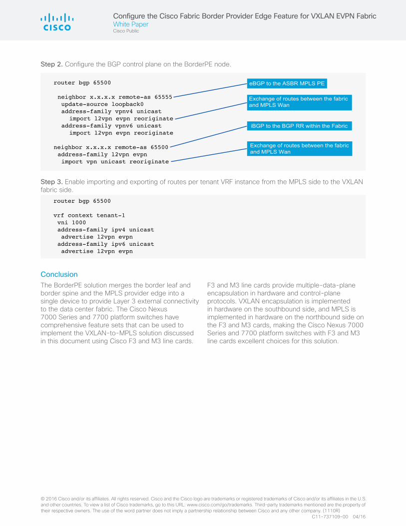
Step 2. Configure the BGP control plane on the BorderPE node.
eBGP to the ASBR MPLS PE
iBGP to the BGP RR within the Fabric
Exchange of routes between the fabric and MPLS Wan
Exchange of routes between the fabric and MPLS Wan
router bgp 65500
neighbor x.x.x.x remote-as 65555 update-source loopback0 address-family vpnv4 unicast import l2vpn evpn reoriginate address-family vpnv6 unicast import l2vpn evpn reoriginate
neighbor x.x.x.x remote-as 65500 address-family l2vpn evpn import vpn unicast reoriginate
Step 3. Enable importing and exporting of routes per tenant VRF instance from the MPLS side to the VXLAN fabric side.
router bgp 65500
vrf context tenant-1 vni 1000 address-family ipv4 unicast advertise l2vpn evpn address-family ipv6 unicast advertise l2vpn evpn
ConclusionThe BorderPE solution merges the border leaf and border spine and the MPLS provider edge into a single device to provide Layer 3 external connectivity to the data center fabric. The Cisco Nexus 7000 Series and 7700 platform switches have comprehensive feature sets that can be used to implement the VXLAN-to-MPLS solution discussed in this document using Cisco F3 and M3 line cards.
F3 and M3 line cards provide multiple-data-plane encapsulation in hardware and control-plane protocols. VXLAN encapsulation is implemented in hardware on the southbound side, and MPLS is implemented in hardware on the northbound side on the F3 and M3 cards, making the Cisco Nexus 7000 Series and 7700 platform switches with F3 and M3 line cards excellent choices for this solution.