Embed Size (px)
Citation preview

Cisco ASA Se
C H A P T E R 10
Configuring a Cluster of ASAsClustering lets you group multiple ASAs together as a single logical device. A cluster provides all the convenience of a single device (management, integration into a network) while achieving the increased throughput and redundancy of multiple devices.
Note Some features are not supported when using clustering. See the “Unsupported Features” section on page 10-20.
• Information About ASA Clustering, page 10-1
• Licensing Requirements for ASA Clustering, page 10-27
• Prerequisites for ASA Clustering, page 10-27
• Guidelines and Limitations, page 10-28
• Default Settings, page 10-32
• Configuring ASA Clustering, page 10-32
• Managing ASA Cluster Members, page 10-59
• Monitoring the ASA Cluster, page 10-70
• Configuration Examples for ASA Clustering, page 10-72
• Feature History for ASA Clustering, page 10-88
Information About ASA Clustering• How the ASA Cluster Fits into Your Network, page 10-2
• Performance Scaling Factor, page 10-2
• Cluster Members, page 10-2
• ASA Cluster Interfaces, page 10-4
• Cluster Control Link, page 10-6
• High Availability within the ASA Cluster, page 10-9
• Configuration Replication, page 10-11
• ASA Cluster Management, page 10-11
• Load Balancing Methods, page 10-13
10-1ries General Operations ASDM Configuration Guide

Chapter 10 Configuring a Cluster of ASAs Information About ASA Clustering
• Inter-Site Clustering, page 10-16
• How the ASA Cluster Manages Connections, page 10-18
• ASA Features and Clustering, page 10-20
How the ASA Cluster Fits into Your NetworkThe cluster consists of multiple ASAs acting as a single unit. (See the “Licensing Requirements for ASA Clustering” section on page 10-27 for the number of units supported per model). To act as a cluster, the ASAs need the following infrastructure:
• Isolated, high-speed backplane network for intra-cluster communication, known as the cluster control link. See the “Cluster Control Link” section on page 10-6.
• Management access to each ASA for configuration and monitoring. See the “ASA Cluster Management” section on page 10-11.
When you place the cluster in your network, the upstream and downstream routers need to be able to load-balance the data coming to and from the cluster using one of the following methods:
• Spanned EtherChannel (Recommended)—Interfaces on multiple members of the cluster are grouped into a single EtherChannel; the EtherChannel performs load balancing between units. See the “Spanned EtherChannel (Recommended)” section on page 10-13.
• Policy-Based Routing (Routed firewall mode only)—The upstream and downstream routers perform load balancing between units using route maps and ACLs. See the “Policy-Based Routing (Routed Firewall Mode Only)” section on page 10-15.
• Equal-Cost Multi-Path Routing (Routed firewall mode only)—The upstream and downstream routers perform load balancing between units using equal cost static or dynamic routes. See the “Equal-Cost Multi-Path Routing (Routed Firewall Mode Only)” section on page 10-16.
Performance Scaling FactorWhen you combine multiple units into a cluster, you can expect a performance of approximately:
• 70% of the combined throughput
• 60% of maximum connections
• 50% of connections per second
For example, for throughput, the ASA 5585-X with SSP-40 can handle approximately 10 Gbps of real world firewall traffic when running alone. For a cluster of 8 units, the maximum combined throughput will be approximately 70% of 80 Gbps (8 units x 10 Gbps): 56 Gbps.
Cluster Members• ASA Hardware and Software Requirements, page 10-3
• Bootstrap Configuration, page 10-3
• Master and Slave Unit Roles, page 10-3
• Master Unit Election, page 10-3
10-2Cisco ASA Series General Operations ASDM Configuration Guide

Chapter 10 Configuring a Cluster of ASAs Information About ASA Clustering
ASA Hardware and Software Requirements
All units in a cluster:
• Must be the same model with the same DRAM. You do not have to have the same amount of flash memory.
• Must run the identical software except at the time of an image upgrade. Hitless upgrade is supported. See the “Upgrade Path and Migrations” section on page 46-1.
• (9.1.3 and Earlier) Must be in the same geographical location. (9.1(4) and later) You can have cluster members in different geographical locations (inter-site) when using individual interface mode. See the “Inter-Site Clustering” section on page 10-16 for more information.
• Must be in the same security context mode, single or multiple.
• (Single context mode) Must be in the same firewall mode, routed or transparent.
• New cluster members must use the same SSL encryption setting (the ssl encryption command) as the master unit for initial cluster control link communication before configuration replication.
• Must have the same cluster, encryption and, for the ASA 5585-X, 10 GE I/O licenses.
Bootstrap Configuration
On each device, you configure a minimal bootstrap configuration including the cluster name, cluster control link interface, and other cluster settings. The first unit on which you enable clustering typically becomes the master unit. When you enable clustering on subsequent units, they join the cluster as slaves.
Master and Slave Unit Roles
One member of the cluster is the master unit. The master unit is determined by the priority setting in the bootstrap configuration; the priority is set between 1 and 100, where 1 is the highest priority. All other members are slave units. Typically, when you first create a cluster, the first unit you add becomes the master unit simply because it is the only unit in the cluster so far.
You must perform all configuration (aside from the bootstrap configuration) on the master unit only; the configuration is then replicated to the slave units. In the case of physical assets, such as interfaces, the configuration of the master unit is mirrored on all slave units. For example, if you configure GigabitEthernet 0/1 as the inside interface and GigabitEthernet 0/0 as the outside interface, then these interfaces are also used on the slave units as inside and outside interfaces.
Some features do not scale in a cluster, and the master unit handles all traffic for those features. See the “Centralized Features” section on page 10-21.
Master Unit Election
Members of the cluster communicate over the cluster control link to elect a master unit as follows:
1. When you enable clustering for a unit (or when it first starts up with clustering already enabled), it broadcasts an election request every 3 seconds.
2. Any other units with a higher priority respond to the election request; the priority is set between 1 and 100, where 1 is the highest priority.
3. If after 45 seconds, a unit does not receive a response from another unit with a higher priority, then it becomes master.
10-3Cisco ASA Series General Operations ASDM Configuration Guide

Chapter 10 Configuring a Cluster of ASAs Information About ASA Clustering
Note If multiple units tie for the highest priority, the cluster unit name and then the serial number is used to determine the master.
4. If a unit later joins the cluster with a higher priority, it does not automatically become the master unit; the existing master unit always remains as the master unless it stops responding, at which point a new master unit is elected.
Note You can manually force a unit to become the master. For centralized features, if you force a master unit change, then all connections are dropped, and you have to re-establish the connections on the new master unit. See the “Centralized Features” section on page 10-21 for a list of centralized features.
ASA Cluster InterfacesYou can configure data interfaces as either Spanned EtherChannels or as Individual interfaces. All data interfaces in the cluster must be one type only.
• Interface Types, page 10-4
• Interface Type Mode, page 10-6
Interface Types
• Spanned EtherChannel (Recommended)
You can group one or more interfaces per unit into an EtherChannel that spans all units in the cluster. The EtherChannel aggregates the traffic across all the available active interfaces in the channel. A Spanned EtherChannel can be configured in both routed and transparent firewall modes. In routed mode, the EtherChannel is configured as a routed interface with a single IP address. In transparent mode, the IP address is assigned to the bridge group, not to the interface. The EtherChannel inherently provides load balancing as part of basic operation. See also the “Spanned EtherChannel (Recommended)” section on page 10-13.
10-4Cisco ASA Series General Operations ASDM Configuration Guide

Chapter 10 Configuring a Cluster of ASAs Information About ASA Clustering
• Individual interfaces (Routed firewall mode only)
Individual interfaces are normal routed interfaces, each with their own Local IP address. Because interface configuration must be configured only on the master unit, the interface configuration lets you set a pool of IP addresses to be used for a given interface on the cluster members, including one for the master. The Main cluster IP address is a fixed address for the cluster that always belongs to the current master unit. The Main cluster IP address is a secondary IP address for the master unit; the Local IP address is always the primary address for routing. The Main cluster IP address provides consistent management access to an address; when a master unit changes, the Main cluster IP address moves to the new master unit, so management of the cluster continues seamlessly. Load balancing, however, must be configured separately on the upstream switch in this case. For information about load balancing, see the “Load Balancing Methods” section on page 10-13.
Note We recommend Spanned EtherChannels instead of Individual interfaces because Individual interfaces rely on routing protocols to load-balance traffic, and routing protocols often have slow convergence during a link failure.
ASA1
ASA2
ASA3
ASA4
ten0/8 ten0/9
ten0/9
ten0/9
ten0/9
ten0/8
ten0/8
ten0/8
port-channel 5 port-channel 6
InsideSpanned
port-channel 110.1.1.1
OutsideSpanned
port-channel 2209.165.201.1
Outside SwitchInside Switch
3333
61
10-5Cisco ASA Series General Operations ASDM Configuration Guide

Chapter 10 Configuring a Cluster of ASAs Information About ASA Clustering
Interface Type Mode
You must choose the interface type (Spanned EtherChannel or Individual) before you configure your devices. See the following guidelines for the interface type mode:
• You can always configure the management-only interface as an Individual interface (recommended), even in Spanned EtherChannel mode. The management interface can be an Individual interface even in transparent firewall mode.
• In Spanned EtherChannel mode, if you configure the management interface as an Individual interface, you cannot enable dynamic routing for the management interface. You must use a static route.
• In multiple context mode, you must choose one interface type for all contexts. For example, if you have a mix of transparent and routed mode contexts, you must use Spanned EtherChannel mode for all contexts because that is the only interface type allowed for transparent mode.
Cluster Control LinkEach unit must dedicate at least one hardware interface as the cluster control link.
• Cluster Control Link Traffic Overview, page 10-7
• Cluster Control Link Interfaces and Network, page 10-7
• Sizing the Cluster Control Link, page 10-7
• Cluster Control Link Redundancy, page 10-8
ASA1/Master
ASA2
ASA3
ASA4
inside ten0/810.1.1.1 (master)
10.1.1.2 (local)
inside ten0/810.1.1.3 (local)
inside ten0/810.1.1.4 (local)
inside ten0/810.1.1.5 (local)
ten0/9 outside209.165.201.1 (master)209.165.201.2 (local)
ten0/9 outside209.165.201.3 (local)
ten0/9 outside209.165.201.4 (local)
ten0/9 outside209.165.201.5 (local)
ten0/0
Load Balancing:PBR or ECMP
Load Balancing:PBR or ECMP
ten0/1
ten0/2
ten0/3
ten0/0
ten0/1
ten0/2
ten0/3
Outside SwitchInside Switch
3333
59
10-6Cisco ASA Series General Operations ASDM Configuration Guide

Chapter 10 Configuring a Cluster of ASAs Information About ASA Clustering
• Cluster Control Link Reliability, page 10-8
• Cluster Control Link Failure, page 10-9
Cluster Control Link Traffic Overview
Cluster control link traffic includes both control and data traffic.
Control traffic includes:
• Master election. (See the “Cluster Members” section on page 10-2.)
• Configuration replication. (See the “Configuration Replication” section on page 10-11.)
• Health monitoring. (See the “Unit Health Monitoring” section on page 10-9.)
Data traffic includes:
• State replication. (See the “Data Path Connection State Replication” section on page 10-10.)
• Connection ownership queries and data packet forwarding. (See the “Rebalancing New TCP Connections Across the Cluster” section on page 10-20.)
Cluster Control Link Interfaces and Network
You can use any data interface(s) for the cluster control link, with the following exceptions:
• You cannot use a VLAN subinterface as the cluster control link.
• You cannot use a Management x/x interface as the cluster control link, either alone or as an EtherChannel.
• For the ASA 5585-X with an ASA IPS module, you cannot use the module interfaces for the cluster control link; you can, however, use interfaces on the ASA 5585-X Network Module.
You can use an EtherChannel or redundant interface; see the “Cluster Control Link Redundancy” section on page 10-8 for more information.
For the ASA 5585-X with SSP-10 and SSP-20, which include two Ten Gigabit Ethernet interfaces, we recommend using one interface for the cluster control link, and the other for data (you can use subinterfaces for data). Although this setup does not accommodate redundancy for the cluster control link, it does satisfy the need to size the cluster control link to match the size of the data interfaces. See the “Sizing the Cluster Control Link” section on page 10-7 for more information.
Each cluster control link has an IP address on the same subnet. This subnet should be isolated from all other traffic, and should include only the ASA cluster control link interfaces.
For a 2-member cluster, do not directly-connect the cluster control link from one ASA to the other ASA. If you directly connect the interfaces, then when one unit fails, the cluster control link fails, and thus the remaining healthy unit fails. If you connect the cluster control link through a switch, then the cluster control link remains up for the healthy unit.
Sizing the Cluster Control Link
You should size the cluster control link to match the expected throughput of each member. For example, if you have the ASA 5585-X with SSP-60, which can pass 14 Gbps per unit maximum in a cluster, then you should also assign interfaces to the cluster control link that can pass at least 14 Gbps. In this case, you could use 2 Ten Gigabit Ethernet interfaces in an EtherChannel for the cluster control link, and use the rest of the interfaces as desired for data links.
10-7Cisco ASA Series General Operations ASDM Configuration Guide

Chapter 10 Configuring a Cluster of ASAs Information About ASA Clustering
Cluster control link traffic is comprised mainly of state update and forwarded packets. The amount of traffic at any given time on the cluster control link varies. For example state updates could consume up to 10% of the through traffic amount if through traffic consists exclusively of short-lived TCP connections. The amount of forwarded traffic depends on the load-balancing efficacy or whether there is a lot of traffic for centralized features. For example:
• NAT results in poor load balancing of connections, and the need to rebalance all returning traffic to the correct units.
• AAA for network access is a centralized feature, so all traffic is forwarded to the master unit.
• When membership changes, the cluster needs to rebalance a large number of connections, thus temporarily using a large amount of cluster control link bandwidth.
A higher-bandwidth cluster control link helps the cluster to converge faster when there are membership changes and prevents throughput bottlenecks.
Note If your cluster has large amounts of asymmetric (rebalanced) traffic, then you should increase the cluster control link size.
(9.1(4) and later) For inter-site clusters and sizing the data center interconnect for cluster control link traffic, see the “Inter-Site Clustering” section on page 10-16.
Cluster Control Link Redundancy
We recommend using an EtherChannel for the cluster control link, so you can pass traffic on multiple links in the EtherChannel while still achieving redundancy.
The following diagram shows how to use an EtherChannel as a cluster control link in a Virtual Switching System (VSS) or Virtual Port Channel (vPC) environment. All links in the EtherChannel are active. When the switch is part of a VSS or vPC, then you can connect ASA interfaces within the same EtherChannel to separate switches in the VSS or vPC. The switch interfaces are members of the same EtherChannel port-channel interface, because the separate switches act like a single switch. Note that this EtherChannel is device-local, not a Spanned EtherChannel.
Cluster Control Link Reliability
(9.1(4) and later) To ensure cluster control link functionality, be sure the round-trip time (RTT) between units is less than 20 ms. This maximum latency enhances compatibility with cluster members installed at different geographical sites. To check your latency, perform a ping on the cluster control link between units.
Switch SwitchVirtual Switch Link
3332
22
ASA1 ASA2 ASA3
10-8Cisco ASA Series General Operations ASDM Configuration Guide
Chapter 10 Configuring a Cluster of ASAs Information About ASA Clustering
The cluster control link must be reliable, with no out-of-order or dropped packets; for example, for inter-site deployment, you should use a dedicated link.
Cluster Control Link Failure
If the cluster control link line protocol goes down for a unit, then clustering is disabled; data interfaces are shut down. After you fix the cluster control link, you must manually rejoin the cluster by re-enabling clustering; see Rejoining the Cluster, page 10-10.
Note When an ASA becomes inactive, all data interfaces are shut down; only the management-only interface can send and receive traffic. The management interface remains up using the IP address the unit received from the cluster IP pool. However if you reload, and the unit is still inactive in the cluster, the management interface is not accessible (because it then uses the Main IP address, which is the same as the master unit). You must use the console port for any further configuration.
High Availability within the ASA Cluster• Unit Health Monitoring, page 10-9
• Interface monitoring, page 10-9
• Unit or Interface Failure, page 10-9
• Data Path Connection State Replication, page 10-10
Unit Health Monitoring
The master unit monitors every slave unit by sending keepalive messages over the cluster control link periodically (the period is configurable). Each slave unit monitors the master unit using the same mechanism.
Interface monitoring
Each unit monitors the link status of all hardware interfaces in use, and reports status changes to the master unit.
• Spanned EtherChannel—Uses cluster Link Aggregation Control Protocol (cLACP). Each unit monitors the link status and the cLACP protocol messages to determine if the port is still active in the EtherChannel. The status is reported to the master unit.
• Individual interfaces (Routed mode only)—Each unit self-monitors its interfaces and reports interface status to the master unit.
Unit or Interface Failure
When health monitoring is enabled, a unit is removed from the cluster if it fails or if its interfaces fail. If an interface fails on a particular unit, but the same interface is active on other units, then the unit is removed from the cluster. The amount of time before the ASA removes a member from the cluster depends on the type of interface and whether the unit is an established member or is joining the cluster. For EtherChannels (spanned or not), if the interface is down on an established member, then the ASA
10-9Cisco ASA Series General Operations ASDM Configuration Guide

Chapter 10 Configuring a Cluster of ASAs Information About ASA Clustering
removes the member after 9 seconds. If the unit is joining the cluster as a new member, the ASA waits 45 seconds before rejecting the new unit. For non-EtherChannels, the unit is removed after 500 ms, regardless of the member state.
When a unit in the cluster fails, the connections hosted by that unit are seamlessly transferred to other units; state information for traffic flows is shared over the control cluster link.
If the master unit fails, then another member of the cluster with the highest priority (lowest number) becomes the master.
The ASA automatically tries to rejoin the cluster; see Rejoining the Cluster, page 10-10.
Note When an ASA becomes inactive and fails to automatically rejoin the cluster, all data interfaces are shut down; only the management-only interface can send and receive traffic. The management interface remains up using the IP address the unit received from the cluster IP pool. However if you reload, and the unit is still inactive in the cluster, the management interface is not accessible (because it then uses the Main IP address, which is the same as the master unit). You must use the console port for any further configuration.
Rejoining the Cluster
After a cluster member is removed from the cluster, how it can rejoin the cluster depends on why it was removed:
• Failed cluster control link—After you resolve the problem with the cluster control link, you must manually rejoin the cluster by re-enabling clustering according to Configuring ASA Cluster Parameters, page 10-59.
• Failed data interface—The ASA automatically tries to rejoin at 5 minutes, then at 10 minutes, and finally at 20 minutes. If the join is not successful after 20 minutes, then the ASA disables clustering. After you resolve the problem with the data interface, you have to manually enable clustering according to Configuring ASA Cluster Parameters, page 10-59.
• Failed unit—If the unit was removed from the cluster because of a unit health check failure, then rejoining the cluster depends on the source of the failure. For example, a temporary power failure means the unit will rejoin the cluster when it starts up again as long as the cluster control link is up and clustering is still enabled.
Data Path Connection State Replication
Every connection has one owner and at least one backup owner in the cluster. The backup owner does not take over the connection in the event of a failure; instead, it stores TCP/UDP state information, so that the connection can be seamlessly transferred to a new owner in case of a failure.
If the owner becomes unavailable, the first unit to receive packets from the connection (based on load balancing) contacts the backup owner for the relevant state information so it can become the new owner.
Some traffic requires state information above the TCP or UDP layer. See Table 10-1 for clustering support or lack of support for this kind of traffic.
10-10Cisco ASA Series General Operations ASDM Configuration Guide

Chapter 10 Configuring a Cluster of ASAs Information About ASA Clustering
Configuration ReplicationAll units in the cluster share a single configuration. Except for the initial bootstrap configuration, you can only make configuration changes on the master unit, and changes are automatically replicated to all other units in the cluster.
ASA Cluster Management• Management Network, page 10-11
• Management Interface, page 10-11
• Master Unit Management Vs. Slave Unit Management, page 10-12
• RSA Key Replication, page 10-12
• ASDM Connection Certificate IP Address Mismatch, page 10-12
Management Network
We recommend connecting all units to a single management network. This network is separate from the cluster control link.
Management Interface
For the management interface, we recommend using one of the dedicated management interfaces. You can configure the management interfaces as Individual interfaces (for both routed and transparent modes) or as a Spanned EtherChannel interface.
We recommend using Individual interfaces for management, even if you use Spanned EtherChannels for your data interfaces. Individual interfaces let you connect directly to each unit if necessary, while a Spanned EtherChannel interface only allows remote connection to the current master unit.
Table 10-1 ASA Features Replicated Across the Cluster
Traffic State Support Notes
Up time Yes Keeps track of the system up time.
ARP Table Yes Transparent mode only.
MAC address table Yes Transparent mode only.
User Identity Yes Includes AAA rules (uauth) and identify firewall.
IPv6 Neighbor database Yes
Dynamic routing Yes
SNMP Engine ID No
VPN (Site-to-Site) No VPN sessions will be disconnected if the master unit fails.
10-11Cisco ASA Series General Operations ASDM Configuration Guide
Chapter 10 Configuring a Cluster of ASAs Information About ASA Clustering
Note If you use Spanned EtherChannel interface mode, and configure the management interface as an Individual interface, you cannot enable dynamic routing for the management interface. You must use a static route.
For an Individual interface, the Main cluster IP address is a fixed address for the cluster that always belongs to the current master unit. For each interface, you also configure a range of addresses so that each unit, including the current master, can use a Local address from the range. The Main cluster IP address provides consistent management access to an address; when a master unit changes, the Main cluster IP address moves to the new master unit, so management of the cluster continues seamlessly. The Local IP address is used for routing, and is also useful for troubleshooting.
For example, you can manage the cluster by connecting to the Main cluster IP address, which is always attached to the current master unit. To manage an individual member, you can connect to the Local IP address.
For outbound management traffic such as TFTP or syslog, each unit, including the master unit, uses the Local IP address to connect to the server.
For a Spanned EtherChannel interface, you can only configure one IP address, and that IP address is always attached to the master unit. You cannot connect directly to a slave unit using the EtherChannel interface; we recommend configuring the management interface as an Individual interface so you can connect to each unit. Note that you can use a device-local EtherChannel for management.
Master Unit Management Vs. Slave Unit Management
Aside from the bootstrap configuration, all management and monitoring can take place on the master unit. From the master unit, you can check runtime statistics, resource usage, or other monitoring information of all units. You can also issue a command to all units in the cluster, and replicate the console messages from slave units to the master unit.
You can monitor slave units directly if desired. Although also available from the master unit, you can perform file management on slave units (including backing up the configuration and updating images). The following functions are not available from the master unit:
• Monitoring per-unit cluster-specific statistics.
• Syslog monitoring per unit.
• SNMP
• NetFlow
RSA Key Replication
When you create an RSA key on the master unit, the key is replicated to all slave units. If you have an SSH session to the Main cluster IP address, you will be disconnected if the master unit fails. The new master unit uses the same key for SSH connections, so you do not need to update the cached SSH host key when you reconnect to the new master unit.
ASDM Connection Certificate IP Address Mismatch
By default, a self-signed certificate is used for the ASDM connection based on the Local IP address. If you connect to the Main cluster IP address using ASDM, then a warning message about a mismatched IP address appears because the certificate uses the Local IP address, and not the Main cluster IP address.
10-12Cisco ASA Series General Operations ASDM Configuration Guide

Chapter 10 Configuring a Cluster of ASAs Information About ASA Clustering
You can ignore the message and establish the ASDM connection. However, to avoid this type of warning, you can enroll a certificate that contains the Main cluster IP address and all the Local IP addresses from the IP address pool. You can then use this certificate for each cluster member. For more information, see Chapter 40, “Configuring Digital Certificates.”
Load Balancing MethodsSee also the “ASA Cluster Interfaces” section on page 10-4.
• Spanned EtherChannel (Recommended), page 10-13
• Policy-Based Routing (Routed Firewall Mode Only), page 10-15
• Equal-Cost Multi-Path Routing (Routed Firewall Mode Only), page 10-16
Spanned EtherChannel (Recommended)
You can group one or more interfaces per unit into an EtherChannel that spans all units in the cluster. The EtherChannel aggregates the traffic across all the available active interfaces in the channel.
• Spanned EtherChannel Benefits, page 10-13
• Guidelines for Maximum Throughput, page 10-13
• Load Balancing, page 10-14
• EtherChannel Redundancy, page 10-14
• Connecting to a VSS or vPC, page 10-14
Spanned EtherChannel Benefits
The EtherChannel method of load-balancing is recommended over other methods for the following benefits:
• Faster failure discovery.
• Faster convergence time. Individual interfaces rely on routing protocols to load-balance traffic, and routing protocols often have slow convergence during a link failure.
• Ease of configuration.
For more information about EtherChannels in general (not just for clustering), see the “EtherChannels” section on page 11-5.
Guidelines for Maximum Throughput
To achieve maximum throughput, we recommend the following:
• Use a load balancing hash algorithm that is “symmetric,” meaning that packets from both directions will have the same hash, and will be sent to the same ASA in the Spanned EtherChannel. We recommend using the source and destination IP address (the default) or the source and destination port as the hashing algorithm.
• Use the same type of line cards when connecting the ASAs to the switch so that hashing algorithms applied to all packets are the same.
10-13Cisco ASA Series General Operations ASDM Configuration Guide

Chapter 10 Configuring a Cluster of ASAs Information About ASA Clustering
Load Balancing
The EtherChannel link is selected using a proprietary hash algorithm, based on source or destination IP addresses and TCP and UDP port numbers.
Note On the ASA, do not change the load-balancing algorithm from the default (see the “Customizing the EtherChannel” section on page 11-33). On the switch, we recommend that you use one of the following algorithms: source-dest-ip or source-dest-ip-port (see the Nexus OS or IOS port-channel load-balance command). Do not use a vlan keyword in the load-balance algorithm because it can cause unevenly distributed traffic to the ASAs in a cluster.
The number of links in the EtherChannel affects load balancing. See the “Load Balancing” section on page 11-7 for more information.
Symmetric load balancing is not always possible. If you configure NAT, then forward and return packets will have different IP addresses and/or ports. Return traffic will be sent to a different unit based on the hash, and the cluster will have to redirect most returning traffic to the correct unit. See the “NAT” section on page 10-24 for more information.
EtherChannel Redundancy
The EtherChannel has built-in redundancy. It monitors the line protocol status of all links. If one link fails, traffic is re-balanced between remaining links. If all links in the EtherChannel fail on a particular unit, but other units are still active, then the unit is removed from the cluster.
Connecting to a VSS or vPC
You can include multiple interfaces per ASA in the Spanned EtherChannel. Multiple interfaces per ASA are especially useful for connecting to both switches in a VSS or vPC. Keep in mind that an EtherChannel can have only 8 active interfaces out of 16 maximum; the remaining 8 interfaces are on standby in case of link failure. The following figure shows a 4-ASA cluster and an 8-ASA cluster, both with a total of 16 links in the EtherChannel. The active links are shown as solid lines, while the inactive links are dotted. cLACP load-balancing can automatically choose the best 8 links to be active in the EtherChannel. As shown, cLACP helps achieve load balancing at the link level.
10-14Cisco ASA Series General Operations ASDM Configuration Guide

Chapter 10 Configuring a Cluster of ASAs Information About ASA Clustering
Policy-Based Routing (Routed Firewall Mode Only)
When using Individual interfaces, each ASA interface maintains its own IP address and MAC address. One method of load balancing is Policy-Based Routing (PBR).
We recommend this method if you are already using PBR, and want to take advantage of your existing infrastructure. This method might offer additional tuning options vs. Spanned EtherChannel as well.
PBR makes routing decisions based on a route map and ACL. You must manually divide traffic between all ASAs in a cluster. Because PBR is static, it may not achieve the optimum load balancing result at all times. To achieve the best performance, we recommend that you configure the PBR policy so that forward and return packets of a connection are directed to the same physical ASA. For example, if you have a Cisco router, redundancy can be achieved by using IOS PBR with Object Tracking. IOS Object Tracking monitors each ASA using ICMP ping. PBR can then enable or disable route maps based on reachability of a particular ASA. See the following URLs for more details:
http://www.cisco.com/en/US/products/ps6599/products_white_paper09186a00800a4409.shtml
http://www.cisco.com/en/US/docs/ios/12_3t/12_3t4/feature/guide/gtpbrtrk.html#wp1057830
Note If you use this method of load-balancing, you can use a device-local EtherChannel as an Individual interface.
Router orAccess Switch
Virtual Switch Link
Router orAccess Switch
Virtual Switch Link
3332
15
ASA1
ASA2
ASA3
ASA4
ASA1
ASA8
Switch 2Switch 1Switch 2Switch 1
port-channel1 port-channel1 port-channel1port-channel1
10-15Cisco ASA Series General Operations ASDM Configuration Guide

Chapter 10 Configuring a Cluster of ASAs Information About ASA Clustering
Equal-Cost Multi-Path Routing (Routed Firewall Mode Only)
When using Individual interfaces, each ASA interface maintains its own IP address and MAC address. One method of load balancing is Equal-Cost Multi-Path (ECMP) routing.
We recommend this method if you are already using ECMP, and want to take advantage of your existing infrastructure. This method might offer additional tuning options vs. Spanned EtherChannel as well.
ECMP routing can forward packets over multiple “best paths” that tie for top place in the routing metric. Like EtherChannel, a hash of source and destination IP addresses and/or source and destination ports can be used to send a packet to one of the next hops. If you use static routes for ECMP routing, then an ASA failure can cause problems; the route continues to be used, and traffic to the failed ASA will be lost. If you use static routes, be sure to use a static route monitoring feature such as Object Tracking. We recommend using dynamic routing protocols to add and remove routes, in which case, you must configure each ASA to participate in dynamic routing.
Note If you use this method of load-balancing, you can use a device-local EtherChannel as an Individual interface.
Inter-Site Clustering
9.1(4) and later
• Inter-Site Clustering Guidelines, page 10-16
• Sizing the Data Center Interconnect, page 10-17
• Inter-Site Example, page 10-17
Inter-Site Clustering Guidelines
See the following guidelines for inter-site clustering:
• Individual Interface mode only.
• The cluster control link latency must be less than 20 ms round-trip time (RTT).
• The cluster control link must be reliable, with no out-of-order or dropped packets; for example, you should use a dedicated link.
• Do not configure connection rebalancing (see the “Rebalancing New TCP Connections Across the Cluster” section on page 10-20); you do not want connections rebalanced to cluster members at a different site.
• The cluster implementation does not differentiate between members at multiple sites; therefore, connection roles for a given connection may span across sites (see the “Connection Roles” section on page 10-18). This is expected behavior.
10-16Cisco ASA Series General Operations ASDM Configuration Guide

Chapter 10 Configuring a Cluster of ASAs Information About ASA Clustering
Sizing the Data Center Interconnect
You should reserve bandwidth on the data center interconnect (DCI) for cluster control link traffic equivalent to the following calculation:
If the number of members differs at each site, use the larger number for your calculation. The minimum bandwidth for the DCI should not be less than the size of the cluster control link for one member.
For example:
• For 4 members at 2 sites:
– 4 cluster members total
– 2 members at each site
– 5 Gbps cluster control link per member
Reserved DCI bandwidth = 5 Gbps (2/2 x 5 Gbps).
• For 8 members at 2 sites, the size increases:
– 8 cluster members total
– 4 members at each site
– 5 Gbps cluster control link per member
Reserved DCI bandwidth = 10 Gbps (4/2 x 5 Gbps).
• For 6 members at 3 sites:
– 6 cluster members total
– 3 members at site 1, 2 members at site 2, and 1 member at site 3
– 10 Gbps cluster control link per member
Reserved DCI bandwidth = 15 Gbps (3/2 x 10 Gbps).
• For 2 members at 2 sites:
– 2 cluster members total
– 1 member at each site
– 10 Gbps cluster control link per member
Reserved DCI bandwidth = 10 Gbps (1/2 x 10 Gbps = 5 Gbps; but the minimum bandwidth should not be less than the size of the cluster control link (10 Gbps)).
Inter-Site Example
The following example shows 2 ASA cluster members at each of 2 data centers. The cluster members are connected by the cluster control link over the DCI. The inside and outside routers at each data center use OSPF and PBR or ECMP to load balance the traffic between cluster members. By assigning a higher
# of cluster members per site2
--------------------------------------------------------------------- cluster control link size per member×
10-17Cisco ASA Series General Operations ASDM Configuration Guide

Chapter 10 Configuring a Cluster of ASAs Information About ASA Clustering
cost route across the DCI, traffic stays within each data center unless all ASA cluster members at a given site go down. In the event of a failure of all cluster members at one site, traffic goes from each router over the DCI to the ASA cluster members at the other site.
How the ASA Cluster Manages Connections• Connection Roles, page 10-18
• New Connection Ownership, page 10-19
• Sample Data Flow, page 10-19
• Rebalancing New TCP Connections Across the Cluster, page 10-20
Connection Roles
There are 3 different ASA roles defined for each connection:
• Owner—The unit that initially receives the connection. The owner maintains the TCP state and processes packets. A connection has only one owner.
• Director—The unit that handles owner lookup requests from forwarders and also maintains the connection state to serve as a backup if the owner fails. When the owner receives a new connection, it chooses a director based on a hash of the source/destination IP address and TCP ports, and sends a message to the director to register the new connection. If packets arrive at any unit other than the owner, the unit queries the director about which unit is the owner so it can forward the packets. A connection has only one director.
Cluster ControlCluster Control
Data Center 1
ASA1 ASA2
Cluster Control
Router
Internet
Outside
Router
Inside
Data Center 2
ASA3 ASA4
Cluster Control
Router
Outside
Router
Inside
Data CenterInterconnect
OSPF
OSPF
OSPF OSPF OSPF
OSPF OSPF OSPF
OSPF
OSPFHigher cost route
OSPFHigher cost route
Higher cost routeOSPF
Higher cost route
3709
98
10-18Cisco ASA Series General Operations ASDM Configuration Guide

Chapter 10 Configuring a Cluster of ASAs Information About ASA Clustering
• Forwarder—A unit that forwards packets to the owner. If a forwarder receives a packet for a connection it does not own, it queries the director for the owner, and then establishes a flow to the owner for any other packets it receives for this connection. The director can also be a forwarder. Note that if a forwarder receives the SYN-ACK packet, it can derive the owner directly from a SYN cookie in the packet, so it does not need to query the director. (If you disable TCP sequence randomization, the SYN cookie is not used; a query to the director is required.) For short-lived flows such as DNS and ICMP, instead of querying, the forwarder immediately sends the packet to the director, which then sends them to the owner. A connection can have multiple forwarders; the most efficient throughput is achieved by a good load-balancing method where there are no forwarders and all packets of a connection are received by the owner.
New Connection Ownership
When a new connection is directed to a member of the cluster via load balancing, that unit owns both directions of the connection. If any connection packets arrive at a different unit, they are forwarded to the owner unit over the cluster control link. For best performance, proper external load balancing is required for both directions of a flow to arrive at the same unit, and for flows to be distributed evenly between units. If a reverse flow arrives at a different unit, it is redirected back to the original unit. For more information, see the “Load Balancing Methods” section on page 10-13.
Sample Data Flow
The following example shows the establishment of a new connection.
1. The SYN packet originates from the client and is delivered to an ASA (based on the load balancing method), which becomes the owner. The owner creates a flow, encodes owner information into a SYN cookie, and forwards the packet to the server.
2. The SYN-ACK packet originates from the server and is delivered to a different ASA (based on the load balancing method). This ASA is the forwarder.
3. Because the forwarder does not own the connection, it decodes owner information from the SYN cookie, creates a forwarding flow to the owner, and forwards the SYN-ACK to the owner.
Client
SYN/ACK1. SYN 1. SYN
2. SYN/ACK
4. State
update
3. SYN/AC
K
Director
ASA Cluster
Server
Owner
Forwarder
After step 4, allremaining packetsare forwardeddirectly to the owner.
3334
80
Inside Outside
10-19Cisco ASA Series General Operations ASDM Configuration Guide

Chapter 10 Configuring a Cluster of ASAs Information About ASA Clustering
4. The owner sends a state update to the director, and forwards the SYN-ACK to the client.
5. The director receives the state update from the owner, creates a flow to the owner, and records the TCP state information as well as the owner. The director acts as the backup owner for the connection.
6. Any subsequent packets delivered to the forwarder will be forwarded to the owner.
7. If packets are delivered to any additional units, it will query the director for the owner and establish a flow.
8. Any state change for the flow results in a state update from the owner to the director.
Rebalancing New TCP Connections Across the Cluster
If the load balancing capabilities of the upstream or downstream routers result in unbalanced flow distribution, you can configure overloaded units to redirect new TCP flows to other units. No existing flows will be moved to other units.
ASA Features and Clustering• Unsupported Features, page 10-20
• Centralized Features, page 10-21
• Features Applied to Individual Units, page 10-22
• Dynamic Routing, page 10-22
• Multicast Routing, page 10-24
• NAT, page 10-24
• AAA for Network Access, page 10-25
• Syslog and Netflow, page 10-26
• SNMP, page 10-26
• VPN, page 10-26
• FTP, page 10-26
• Cisco TrustSec, page 10-27
Unsupported Features
These features cannot be configured with clustering enabled, and the commands will be rejected.
• Unified Communications
• Remote access VPN (SSL VPN and IPsec VPN)
• The following application inspections:
– CTIQBE
– GTP
– H323, H225, and RAS
– IPsec passthrough
– MGCP
10-20Cisco ASA Series General Operations ASDM Configuration Guide

Chapter 10 Configuring a Cluster of ASAs Information About ASA Clustering
– MMP
– RTSP
– SIP
– SCCP (Skinny)
– WAAS
– WCCP
• Botnet Traffic Filter
• Auto Update Server
• DHCP client, server, relay, and proxy
• VPN load balancing
• Failover
• ASA CX module
Centralized Features
The following features are only supported on the master unit, and are not scaled for the cluster. For example, you have a cluster of eight units (5585-X with SSP-60). The Other VPN license allows a maximum of 10,000 site-to-site IPsec tunnels for one ASA 5585-X with SSP-60. For the entire cluster of eight units, you can only use 10,000 tunnels; the feature does not scale.
Note Traffic for centralized features is forwarded from member units to the master unit over the cluster control link; see the “Sizing the Cluster Control Link” section on page 10-7 to ensure adequate bandwidth for the cluster control link.
If you use the rebalancing feature (see the “Rebalancing New TCP Connections Across the Cluster” section on page 10-20), traffic for centralized features may be rebalanced to non-master units before the traffic is classified as a centralized feature; if this occurs, the traffic is then sent back to the master unit.
For centralized features, if the master unit fails, all connections are dropped, and you have to re-establish the connections on the new master unit.
• Site-to-site VPN
• The following application inspections:
– DCERPC
– NetBios
– PPTP
– RADIUS
– RSH
– SUNRPC
– TFTP
– XDMCP
• Dynamic routing (Spanned EtherChannel mode only)
10-21Cisco ASA Series General Operations ASDM Configuration Guide

Chapter 10 Configuring a Cluster of ASAs Information About ASA Clustering
• Multicast routing (Individual interface mode only)
• Static route monitoring
• IGMP multicast control plane protocol processing (data plane forwarding is distributed across the cluster)
• PIM multicast control plane protocol processing (data plane forwarding is distributed across the cluster)
• Authentication and Authorization for network access. Accounting is decentralized.
• Filtering Services
Features Applied to Individual Units
These features are applied to each ASA unit, instead of the cluster as a whole or to the master unit.
• QoS—The QoS policy is synced across the cluster as part of configuration replication. However, the policy is enforced on each unit independently. For example, if you configure policing on output, then the conform rate and conform burst values are enforced on traffic exiting a particular ASA. In a cluster with 8 units and with traffic evenly distributed, the conform rate actually becomes 8 times the rate for the cluster.
• Threat detection—Threat detection works on each unit independently; for example, the top statistics is unit-specific. Port scanning detection, for example, does not work because scanning traffic will be load-balanced between all units, and one unit will not see all traffic.
• Resource management—Resource management in multiple context mode is enforced separately on each unit based on local usage.
• IPS module—There is no configuration sync or state sharing between IPS modules. Some IPS signatures require IPS to keep the state across multiple connections. For example, the port scanning signature is used when the IPS module detects that someone is opening many connections to one server but with different ports. In clustering, those connections will be balanced between multiple ASA devices, each of which has its own IPS module. Because these IPS modules do not share state information, the cluster may not be able to detect port scanning as a result.
Dynamic Routing
• Dynamic Routing in Spanned EtherChannel Mode, page 10-22
• Dynamic Routing in Individual Interface Mode, page 10-23
Dynamic Routing in Spanned EtherChannel Mode
In Spanned EtherChannel mode, the routing process only runs on the master unit, and routes are learned through the master unit and replicated to slaves. If a routing packet arrives at a slave, it is redirected to the master unit.
10-22Cisco ASA Series General Operations ASDM Configuration Guide

Chapter 10 Configuring a Cluster of ASAs Information About ASA Clustering
Figure 10-1 Dynamic Routing in Spanned EtherChannel Mode
After the slave members learn the routes from the master unit, each unit makes forwarding decisions independently.
The OSPF LSA database is not synchronized from the master unit to slave units. If there is a master unit switchover, the neighboring router will detect a restart; the switchover is not transparent. The OSPF process picks an IP address as its router ID. Although not required, you can assign a static router ID to ensure a consistent router ID is used across the cluster.
Dynamic Routing in Individual Interface Mode
In Individual interface mode, each unit runs the routing protocol as a standalone router, and routes are learned by each unit independently.
2858
95
Router A
Router B
ASAs
EtherChannelLoad Balancing
Only master ASA uses OSPFwith neighboring routers.Slave ASAs are invisible.
10-23Cisco ASA Series General Operations ASDM Configuration Guide

Chapter 10 Configuring a Cluster of ASAs Information About ASA Clustering
Figure 10-2 Dynamic Routing in Individual Interface Mode
In the above diagram, Router A learns that there are 4 equal-cost paths to Router B, each through an ASA. ECMP is used to load balance traffic between the 4 paths. Each ASA picks a different router ID when talking to external routers.
You must configure a cluster pool for the router ID so that each unit has a separate router ID.
Multicast Routing
• Multicast Routing in Spanned EtherChannel Mode, page 10-24
• Multicast Routing in Individual Interface Mode, page 10-24
Multicast Routing in Spanned EtherChannel Mode
In Spanned EtherChannel mode, the master unit handles all multicast routing packets and data packets until fast-path forwarding is established. After the connection is established, each slave can forward multicast data packets.
Multicast Routing in Individual Interface Mode
In Individual interface mode, units do not act independently with multicast. All data and routing packets are processed and forwarded by the master unit, thus avoiding packet replication.
NAT
NAT can impact the overall throughput of the cluster. Inbound and outbound NAT packets can be sent to different ASAs in the cluster because the load balancing algorithm relies on IP addresses and ports, and NAT causes inbound and outbound packets to have different IP addresses and/or ports. When a packet arrives at an ASA that is not the connection owner, it is forwarded over the cluster control link to the owner, causing large amounts of traffic on the cluster control link.
2858
96
Router A
Router B
ASAs
ECMP Load BalancingAll ASAs are using OSPFwith neighboring routers
10-24Cisco ASA Series General Operations ASDM Configuration Guide

Chapter 10 Configuring a Cluster of ASAs Information About ASA Clustering
If you still want to use NAT in clustering, then consider the following guidelines:
• No Proxy ARP—For Individual interfaces, a proxy ARP reply is never sent for mapped addresses. This prevents the adjacent router from maintaining a peer relationship with an ASA that may no longer be in the cluster. The upstream router needs a static route or PBR with Object Tracking for the mapped addresses that points to the Main cluster IP address. This is not an issue for a Spanned EtherChannel, because there is only one IP address associated with the cluster interface.
• No interface PAT on an Individual interface—Interface PAT is not supported for Individual interfaces.
• NAT pool address distribution for dynamic PAT—The master unit evenly pre-distributes addresses across the cluster. If a member receives a connection and they have no addresses left, the connection is dropped, even if other members still have addresses available. Make sure to include at least as many NAT addresses as there are units in the cluster to ensure that each unit receives an address. Use the show nat pool cluster command to see the address allocations.
• No round-robin—Round-robin for a PAT pool is not supported with clustering.
• Dynamic NAT xlates managed by the master unit—The master unit maintains and replicates the xlate table to slave units. When a slave unit receives a connection that requires dynamic NAT, and the xlate is not in the table, it requests the xlate from the master unit. The slave unit owns the connection.
• Per-session PAT feature—Although not exclusive to clustering, the per-session PAT feature improves the scalability of PAT and, for clustering, allows each slave unit to own PAT connections; by contrast, multi-session PAT connections have to be forwarded to and owned by the master unit. By default, all TCP traffic and UDP DNS traffic use a per-session PAT xlate. For traffic that requires multi-session PAT, such as H.323, SIP, or Skinny, you can disable per-session PAT. For more information about per-session PAT, see the Per-Session PAT vs. Multi-Session PAT section in the firewall configuration guide.
• No static PAT for the following inspections—
– FTP
– PPTP
– RSH
– SQLNET
– TFTP
– XDMCP
– All Voice-over-IP applications
AAA for Network Access
AAA for network access consists of three components: authentication, authorization, and accounting. Authentication and accounting are implemented as centralized features on the clustering master with replication of the data structures to the cluster slaves. If a master is elected, the new master will have all the information it needs to continue uninterrupted operation of the established authenticated users and their associated authorizations. Idle and absolute timeouts for user authentications are preserved when a master unit change occurs.
Accounting is implemented as a distributed feature in a cluster. Accounting is done on a per-flow basis, so the cluster unit owning a flow will send accounting start and stop messages to the AAA server when accounting is configured for a flow.
10-25Cisco ASA Series General Operations ASDM Configuration Guide

Chapter 10 Configuring a Cluster of ASAs Information About ASA Clustering
Syslog and Netflow
• Syslog—Each unit in the cluster generates its own syslog messages. You can configure logging so that each unit uses either the same or a different device ID in the syslog message header field. For example, the hostname configuration is replicated and shared by all units in the cluster. If you configure logging to use the hostname as the device ID, syslog messages generated by all units look as if they come from a single unit. If you configure logging to use the local-unit name that is assigned in the cluster bootstrap configuration as the device ID, syslog messages look as if they come from different units. See the “Including the Device ID in Non-EMBLEM Format Syslog Messages” section on page 41-22.
• NetFlow—Each unit in the cluster generates its own NetFlow stream. The NetFlow collector can only treat each ASA as a separate NetFlow exporter.
SNMP
An SNMP agent polls each individual ASA by its Local IP address. You cannot poll consolidated data for the cluster.
You should always use the Local address, and not the Main cluster IP address for SNMP polling. If the SNMP agent polls the Main cluster IP address, if a new master is elected, the poll to the new master unit will fail.
VPN
Site-to-site VPN is a centralized feature; only the master unit supports VPN connections.
Note Remote access VPN is not supported with clustering.
VPN functionality is limited to the master unit and does not take advantage of the cluster high availability capabilities. If the master unit fails, all existing VPN connections are lost, and VPN users will see a disruption in service. When a new master is elected, you must reestablish the VPN connections.
When you connect a VPN tunnel to a Spanned EtherChannel address, connections are automatically forwarded to the master unit. For connections to an Individual interface when using PBR or ECMP, you must always connect to the Main cluster IP address, not a Local address.
VPN-related keys and certificates are replicated to all units.
FTP
• If FTP data channel and control channel flows are owned by different cluster members, the data channel owner will periodically send idle timeout updates to the control channel owner and update the idle timeout value. However, if the control flow owner is reloaded, and the control flow is re-hosted, the parent/child flow relationship will not longer be maintained; the control flow idle timeout will not be updated.
• If you use AAA for FTP access, then the control channel flow is centralized on the master unit.
10-26Cisco ASA Series General Operations ASDM Configuration Guide

Chapter 10 Configuring a Cluster of ASAs Licensing Requirements for ASA Clustering
Cisco TrustSec
Only the master unit learns security group tag (SGT) information. The master unit then populates the SGT to slaves, and slaves can make a match decision for SGT based on the security policy.
Licensing Requirements for ASA Clustering
Prerequisites for ASA ClusteringSwitch Prerequisites
• Be sure to complete the switch configuration before you configure clustering on the ASAs.
• Table 10-2 lists supported external hardware and software to interoperate with ASA clustering.
ASA Prerequisites
• Provide each unit with a unique IP address before you join them to the management network.
Model License Requirement
ASA 5580, ASA 5585-X
Cluster License, supports up to 8 units.
A Cluster license is required on each unit. For other feature licenses, cluster units do not require the same license on each unit. If you have feature licenses on multiple units, they combine into a single running ASA cluster license.
Note Each unit must have the same encryption license and the same 10 GE I/O license.
ASA 5512-X1
1. Supported in 9.1(4) and later.
Security Plus license, supports 2 units.
Note Each unit must have the same encryption license.
ASA 5515-X, ASA 5525-X, ASA 5545-X, ASA 5555-X1
Base License, supports 2 units.
Note Each unit must have the same encryption license.
All other models No support.
Table 10-2 External Hardware and Software Dependencies for ASA Clustering
External Hardware External Software ASA Version
Nexus 7000 NXOS 5.2(5) and later 9.0(1) and later.
Nexus 5000 NXOS 7.0(1) and later 9.1(4) and later.
Catalyst 6500 with Supervisor 32, 720, and 720-10GE
IOS 12.2(33)SXI7, SXI8, and SXI9 and later
9.0(1) and later.
Catalyst 3750-X IOS 15.0(2) and later 9.1(4) and later.
10-27Cisco ASA Series General Operations ASDM Configuration Guide

Chapter 10 Configuring a Cluster of ASAs Guidelines and Limitations
– See Chapter 3, “Getting Started,” for more information about connecting to the ASA and setting the management IP address.
– Except for the IP address used by the master unit (typically the first unit you add to the cluster), these management IP addresses are for temporary use only.
– After a slave joins the cluster, its management interface configuration is replaced by the one replicated from the master unit.
• To use jumbo frames on the cluster control link (recommended), you must enable Jumbo Frame Reservation before you enable clustering. See the “Enabling Jumbo Frame Support (Supported Models)” section on page 11-39.
• See also the “ASA Hardware and Software Requirements” section on page 10-3.
Other Prerequisites
We recommend using a terminal server to access all cluster member unit console ports. For initial setup, and ongoing management (for example, when a unit goes down), a terminal server is useful for remote management.
Guidelines and LimitationsContext Mode Guidelines
Supported in single and multiple context modes. The mode must match on each member unit.
Firewall Mode Guidelines
Supported in routed and transparent firewall modes. For single mode, the firewall mode must match on all units.
Failover Guidelines
Failover is not supported with clustering.
IPv6 Guidelines
Supports IPv6. However, the cluster control link is only supported using IPv4.
Model Guidelines
Supported on:
• ASA 5585-X
For the ASA 5585-X with SSP-10 and SSP-20, which include two Ten Gigabit Ethernet interfaces, we recommend using one interface for the cluster control link, and the other for data (you can use subinterfaces for data). Although this setup does not accommodate redundancy for the cluster control link, it does satisfy the need to size the cluster control link to match the size of the data interfaces. See the “Sizing the Cluster Control Link” section on page 10-7 for more information.
• ASA 5580
• ASA 5512-X, ASA 5515-X, ASA 5525-X, ASA 5545-X, and ASA 5555-X
Switch Guidelines
• On the switch(es) for the cluster control link interfaces, you can optionally enable Spanning Tree PortFast on the switch ports connected to the ASA to speed up the join process for new units.
10-28Cisco ASA Series General Operations ASDM Configuration Guide

Chapter 10 Configuring a Cluster of ASAs Guidelines and Limitations
• When you see slow bundling of a Spanned EtherChannel on the switch, you can enable LACP rate fast for an Individual interface on the switch.
• On the switch, we recommend that you use one of the following EtherChannel load-balancing algorithms: source-dest-ip or source-dest-ip-port (see the Nexus OS and IOS port-channel load-balance command). Do not use a vlan keyword in the load-balance algorithm because it can cause unevenly distributed traffic to the ASAs in a cluster. Do not change the load-balancing algorithm from the default on the ASA .
• If you change the load-balancing algorithm of the EtherChannel on the switch, the EtherChannel interface on the switch temporarily stops forwarding traffic, and the Spanning Tree Protocol restarts. There will be a delay before traffic starts flowing again.
• You should disable the LACP Graceful Convergence feature on all cluster-facing EtherChannel interfaces for Nexus switches.
EtherChannel Guidelines
• The ASA does not support connecting an EtherChannel to a switch stack. If the ASA EtherChannel is connected cross stack, and if the master switch is powered down, then the EtherChannel connected to the remaining switch will not come up.
• For detailed EtherChannel guidelines, limitations, and prerequisites, see the “Configuring an EtherChannel” section on page 11-30.
• See also the “EtherChannel Guidelines” section on page 11-13.
• Spanned vs. Device-Local EtherChannel Configuration—Be sure to configure the switch appropriately for Spanned EtherChannels vs. Device-local EtherChannels.
– Spanned EtherChannels—For ASA Spanned EtherChannels, which span across all members of the cluster, the interfaces are combined into a single EtherChannel on the switch. Make sure each interface is in the same channel group on the switch.
10-29Cisco ASA Series General Operations ASDM Configuration Guide

Chapter 10 Configuring a Cluster of ASAs Guidelines and Limitations
– Device-local EtherChannels—For ASA Device-local EtherChannels including any EtherChannels configured for the cluster control link, be sure to configure discrete EtherChannels on the switch; do not combine multiple ASA EtherChannels into one EtherChannel on the switch.
VLAN 101port-ch1
RIGHT WRONG
port-ch2
port-ch3
port-ch4
ASA1
Switch Switch
ASA2
ASA3
ASA4
ten0/6
VLAN 101port-ch1
Spanned Data Ifcport-ch1
ten0/6
ten0/6
ten0/6
ASA1
ASA2
ASA3
ASA4
ten0/6
Spanned Data Ifcport-ch1
ten0/6
ten0/6
ten0/6
3346
21
10-30Cisco ASA Series General Operations ASDM Configuration Guide

Chapter 10 Configuring a Cluster of ASAs Guidelines and Limitations
Additional Guidelines
• See the “ASA Hardware and Software Requirements” section on page 10-3.
• For unsupported features with clustering, see the “Unsupported Features” section on page 10-20.
• When significant topology changes occur (such as adding or removing an EtherChannel interface, enabling or disabling an interface on the ASA or the switch, adding an additional switch to form a VSS or vPC) you should disable the health check feature. When the topology change is complete, and the configuration change is synced to all units, you can re-enable the health check feature.
• When adding a unit to an existing cluster, or when reloading a unit, there will be a temporary, limited packet/connection drop; this is expected behavior. In some cases, the dropped packets can hang your connection; for example, dropping a FIN/ACK packet for an FTP connection will make the FTP client hang. In this case, you need to reestablish the FTP connection.
• If you use a Windows 2003 server connected to a Spanned EtherChannel, when the syslog server port is down and the server does not throttle ICMP error messages, then large numbers of ICMP messages are sent back to the ASA cluster. These messages can result in some units of the ASA cluster experiencing high CPU, which can affect performance. We recommend that you throttle ICMP error messages.
ASA1
ASA2
ASA3
ASA4
ten0/6
Cluster Control Linkport-ch1
ten0/7
port-ch1
port-ch1
port-ch1
VLAN 101port-ch1
RIGHT WRONG
port-ch2
port-ch3
port-ch4
ten0/6
ten0/7
ten0/6
ten0/7
ten0/6
ten0/7
ASA1
ASA2
ASA3
ASA4
ten0/6
Cluster Control Linkport-ch1
ten0/7
port-ch1
port-ch1
port-ch1
VLAN 101port-ch1
ten0/6
ten0/7
ten0/6
ten0/7
ten0/6
ten0/7
3333
58
Switch Switch
10-31Cisco ASA Series General Operations ASDM Configuration Guide

Chapter 10 Configuring a Cluster of ASAs Default Settings
Default Settings• When using Spanned EtherChannels, the cLACP system ID is auto-generated and the system
priority is 1 by default.
• The cluster health check feature is enabled by default with the holdtime of 3 seconds.
• Connection rebalancing is disabled by default. If you enable connection rebalancing, the default time between load information exchanges is 5 seconds.
Configuring ASA Clustering
Note To enable or disable clustering, you must use a console connection (for CLI) or an ASDM connection.
• Task Flow for ASA Cluster Configuration, page 10-32
• Cabling the Cluster Units and Configuring Upstream and Downstream Equipment, page 10-33
• Backing Up Your Configurations (Recommended), page 10-35
• Configuring the Cluster Interface Mode on the Master Unit, page 10-35
• (Recommended; Required in Multiple Context Mode) Configuring Interfaces on the Master Unit, page 10-38
• Adding or Joining an ASA Cluster, page 10-50
Task Flow for ASA Cluster ConfigurationTo configure clustering, perform the following steps:
Step 1 Complete all pre-configuration on the switches and ASAs according to the “Prerequisites for ASA Clustering” section on page 10-27.
Step 2 Cable your equipment. Before configuring clustering, cable the cluster control link network, management network, and data networks. See the “Cabling the Cluster Units and Configuring Upstream and Downstream Equipment” section on page 10-33.
Step 3 (Recommended) Back up each unit configuration before you enable clustering. See the “Backing Up Your Configurations (Recommended)” section on page 10-35.
Step 4 Configure the interface mode. You can only configure one type of interface for clustering: Spanned EtherChannels or Individual interfaces. See the “Configuring the Cluster Interface Mode on the Master Unit” section on page 10-35.
Step 5 (Recommended) Configure interfaces for clustering on the master unit. You cannot enable clustering if the interfaces are not cluster-ready. In single context mode, you can alternatively configure many interface settings within the High Availability and Scalability wizard, but not all interface options are available in the wizard, and you cannot configure the interfaces in multiple context mode within the wizard. See the “(Recommended; Required in Multiple Context Mode) Configuring Interfaces on the Master Unit” section on page 10-38.
Step 6 Join the cluster by running the High Availability and Scalability wizard. See the “Adding or Joining an ASA Cluster” section on page 10-50.
10-32Cisco ASA Series General Operations ASDM Configuration Guide

Chapter 10 Configuring a Cluster of ASAs Configuring ASA Clustering
Step 7 Configure the security policy on the master unit. See the chapters in this guide to configure supported features on the master unit. The configuration is replicated to the slave units. For a list of supported and unsupported features, see the “ASA Features and Clustering” section on page 10-20.
Cabling the Cluster Units and Configuring Upstream and Downstream Equipment
Before configuring clustering, cable the cluster control link network, management network, and data networks.
Note At a minimum, an active cluster control link network is required before you configure the units to join the cluster.
You should also configure the upstream and downstream equipment. For example, if you use EtherChannels, then you should configure the upstream and downstream equipment for the EtherChannels.
Examples
Note This example uses EtherChannels for load-balancing. If you are using PBR or ECMP, your switch configuration will differ.
For example on each of 4 ASA 5585-Xs, you want to use:
• 2 Ten Gigabit Ethernet interfaces in a device-local EtherChannel for the cluster control link.
• 2 Ten Gigabit Ethernet interfaces in a Spanned EtherChannel for the inside and outside network; each interface is a VLAN subinterface of the EtherChannel. Using subinterfaces lets both inside and outside interfaces take advantage of the benefits of an EtherChannel.
• 1 Management interface.
You have one switch for both the inside and outside networks.
10-33Cisco ASA Series General Operations ASDM Configuration Guide

Chapter 10 Configuring a Cluster of ASAs Configuring ASA Clustering
Purpose Connect Interfaces on each of 4 ASAs To Switch Ports
Cluster control link TenGigabitEthernet 0/6 and TenGigabitEthernet 0/7
8 ports total
For each TenGigabitEthernet 0/6 and TenGigabitEthernet 0/7 pair, configure 4 EtherChannels (1 EC for each ASA).
These EtherChannels must all be on the same isolated cluster control VLAN, for example VLAN 101.
Inside and outside interfaces TenGigabitEthernet 0/8 and TenGigabitEthernet 0/9
8 ports total
Configure a single EtherChannel (across all ASAs).
On the switch, configure these VLANs and networks now; for example, a trunk including VLAN 200 for the inside and VLAN 201 for the outside.
Management interface Management 0/0 4 ports total
Place all interfaces on the same isolated management VLAN, for example VLAN 100.
ASA1
3331
50
ten0
/6te
n0/7
ten0
/8
man
0/0
ten0
/9
ASA2
ten0
/6te
n0/7
ten0
/8
man
0/0
ten0
/9
ASA3
ten0
/6te
n0/7
ten0
/8
man
0/0
ten0
/9
ASA4
ten0
/6te
n0/7
ten0
/8
man
0/0
ten0
/9
SwitchManagement
VLAN 100
VLAN 101port-ch1
port-ch2 port-ch3 port-ch4
ClusterControl Link
port-ch1
port-ch5Inside VLAN 200
Outside VLAN 201Trunk
port-ch1 port-ch1 port-ch1
port-ch2port-ch2.200 Inside VLAN 200
port-ch2.201 Outside VLAN 201
10-34Cisco ASA Series General Operations ASDM Configuration Guide

Chapter 10 Configuring a Cluster of ASAs Configuring ASA Clustering
What to Do Next
Back up your configuration. See the “Backing Up Your Configurations (Recommended)” section on page 10-35.
Backing Up Your Configurations (Recommended)When you enable clustering on a slave unit, the current configuration is replaced with one synced from the master unit. If you ever want to leave the cluster entirely, it may be useful to have a backup configuration with a usable management interface configuration. See the “Leaving the Cluster” section on page 10-66 for more information.
Guidelines
Perform a backup on each unit.
Detailed Steps
Step 1 Choose Tools > Backup Configurations.
Step 2 Back up at least the running configuration. See the “Backing Up Configurations” section on page 46-21 for a detailed procedure.
What to Do Next
Configure the cluster interface mode on the master unit. See the “Configuring the Cluster Interface Mode on the Master Unit” section on page 10-35.
Configuring the Cluster Interface Mode on the Master UnitYou can only configure one type of interface for clustering: Spanned EtherChannels or Individual interfaces; you cannot mix interface types in a cluster. For exceptions for the management interface and other guidelines, see the “Interface Type Mode” section on page 10-6.
Note If you do not add slave units from the master unit, you must set the interface mode manually on all units according to this section, not just the master unit; if you add slaves from the master, ASDM sets the interface mode automatically on the slave.
Prerequisites
• Transparent firewall mode supports only Spanned EtherChannel mode.
• For multiple context mode, configure this setting in the system execution space; you cannot configure the mode per context.
Detailed Steps
Step 1 In ASDM on the master unit, choose Tools > Command Line Interface.
10-35Cisco ASA Series General Operations ASDM Configuration Guide

Chapter 10 Configuring a Cluster of ASAs Configuring ASA Clustering
Step 2 Enter the following commands:
Caution After you set the interface mode, you can continue to connect to the interface; however, if you reload the ASA before you configure your management interface to comply with clustering requirements (for example, adding a cluster IP pool), you will not be able to reconnect because cluster-incompatible interface configuration is removed. In that case, you will have to connect to the console port to fix the interface configuration. To configure interfaces to be compatible with clustering, see the “(Recommended; Required in Multiple Context Mode) Configuring Interfaces on the Master Unit” section on page 10-38.
For example:
Command Purpose
Step 1 cluster interface-mode {individual | spanned} check-details
Example:cluster interface-mode spanned check-details
The check-details command shows any incompatible configuration so you can force the interface mode and fix your configuration later; the mode is not changed with this command.
Step 2 cluster interface-mode {individual | spanned} force
Example:cluster interface-mode spanned force
Sets the interface mode for clustering. There is no default setting; you must explicitly choose the mode. If you have not set the mode, you cannot enable clustering.
The force option changes the mode without checking your configuration for incompatible settings. You need to manually fix any configuration issues after you change the mode. Because any interface configuration can only be fixed after you set the mode, we recommend using the force option so you can at least start from the existing configuration. You can re-run the check-details option after you set the mode for more guidance.
Without the force option, if there is any incompatible configuration, you are prompted to clear your configuration and reload, thus requiring you to connect to the console port to reconfigure your management access. If your configuration is compatible (rare), the mode is changed and the configuration is preserved. If you do not want to clear your configuration, you can exit the command by typing n.
To remove the interface mode, enter the no cluster interface-mode command.
10-36Cisco ASA Series General Operations ASDM Configuration Guide

Chapter 10 Configuring a Cluster of ASAs Configuring ASA Clustering
Step 3 Quit ASDM and reload. ASDM needs to be restarted to correctly account for the cluster interface mode. After you reload, you see the ASA Cluster tab on the Home Page:
10-37Cisco ASA Series General Operations ASDM Configuration Guide

Chapter 10 Configuring a Cluster of ASAs Configuring ASA Clustering
What to Do Next
Configure interfaces. See the “(Recommended; Required in Multiple Context Mode) Configuring Interfaces on the Master Unit” section on page 10-38.
(Recommended; Required in Multiple Context Mode) Configuring Interfaces on the Master Unit
You must modify any interface that is currently configured with an IP address to be cluster-ready before you enable clustering. At a minimum, you must modify the management interface to which ASDM is currently connected. For other interfaces, you can configure them before or after you enable clustering; we recommend pre-configuring all of your interfaces so that the complete configuration is synced to new cluster members. In multiple context mode, you must use the procedures in this section to fix existing interfaces or to configure new interfaces. However, in single mode, you can skip this section and configure common interface parameters within the High Availability and Scalability wizard (see the “Adding or Joining an ASA Cluster” section on page 10-50). Note that advanced interface settings such as creating EtherChannels for Individual interfaces are not available in the wizard.
This section describes how to configure interfaces to be compatible with clustering. You can configure data interfaces as either Spanned EtherChannels or as Individual interfaces. Each method uses a different load-balancing mechanism. You cannot configure both types in the same configuration, with the exception of the management interface, which can be an Individual interface even in Spanned EtherChannel mode. For more information, see the “ASA Cluster Interfaces” section on page 10-4.
• Configuring Individual Interfaces (Recommended for the Management Interface), page 10-38
• Configuring Spanned EtherChannels, page 10-43
Configuring Individual Interfaces (Recommended for the Management Interface)
Individual interfaces are normal routed interfaces, each with their own IP address taken from a pool of IP addresses. The Main cluster IP address is a fixed address for the cluster that always belongs to the current master unit.
In Spanned EtherChannel mode, we recommend configuring the management interface as an Individual interface. Individual management interfaces let you connect directly to each unit if necessary, while a Spanned EtherChannel interface only allows connection to the current master unit. See the “Management Interface” section on page 10-11 for more information.
10-38Cisco ASA Series General Operations ASDM Configuration Guide

Chapter 10 Configuring a Cluster of ASAs Configuring ASA Clustering
Prerequisites
• Except for the management-only interface, you must be in Individual interface mode; see the “Configuring the Cluster Interface Mode on the Master Unit” section on page 10-35.
• For multiple context mode, perform this procedure in each context. If you are not already in the context configuration mode in the Configuration > Device List pane, double-click the context name under the active device IP address.
• Individual interfaces require you to configure load balancing on neighbor devices. External load balancing is not required for the management interface. For information about load balancing, see the “Load Balancing Methods” section on page 10-13.
• (Optional) Configure the interface as a device-local EtherChannel interface, a redundant interface, and/or configure subinterfaces.
– For an EtherChannel, see the “Configuring an EtherChannel” section on page 11-30. This EtherChannel is local to the unit, and is not a Spanned EtherChannel.
– For a redundant interface, see the “Configuring a Redundant Interface” section on page 11-27. Management-only interfaces cannot be redundant interfaces.
– For subinterfaces, see the “Configuring VLAN Subinterfaces and 802.1Q Trunking” section on page 11-36.
• If you are connecting remotely to the management interface using ASDM, the current IP address of prospective slave units are for temporary use.
– Each member will be assigned an IP address from the cluster IP pool defined on the master unit.
– The cluster IP pool cannot include addresses already in use on the network, including prospective slave IP addresses.
For example:
a. You configure the master unit to use 10.1.1.1.
b. Other units use 10.1.1.2, 10.1.1.3, and 10.1.1.4.
c. When you configure the cluster IP pool on the master unit, you cannot include the .2, .3, or .4 addresses in the pool, because they are in use.
d. Instead, you need to use other IP addresses on the network, such as .5, .6, .7, and .8.
Note The pool needs as many addresses as there are members of the cluster, including the master unit; the original .1 address is the main cluster IP address that belongs to the current master unit.
e. After you join the cluster, the old, temporary addresses are relinquished and can be used elsewhere.
Detailed Steps
Step 1 Choose the Configuration > Device Setup > Interfaces pane.
Step 2 Choose the interface row, and click Edit. Configure the following parameters:
a. (Required for a management interface in Spanned EtherChannel mode) Dedicate this interface to management only—Sets an interface to management-only mode so that it does not pass through traffic. By default, Management type interfaces are configured as management-only. In transparent mode, this command is always enabled for a Management type interface.
10-39Cisco ASA Series General Operations ASDM Configuration Guide
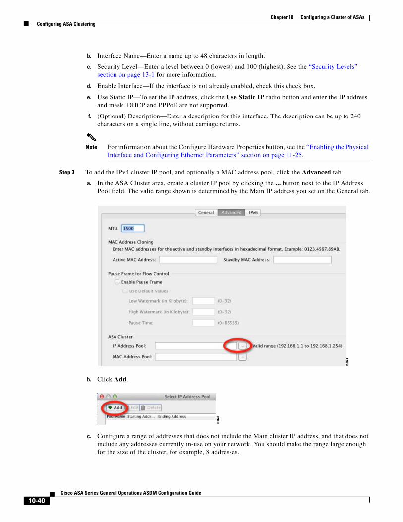
Chapter 10 Configuring a Cluster of ASAs Configuring ASA Clustering
b. Interface Name—Enter a name up to 48 characters in length.
c. Security Level—Enter a level between 0 (lowest) and 100 (highest). See the “Security Levels” section on page 13-1 for more information.
d. Enable Interface—If the interface is not already enabled, check this check box.
e. Use Static IP—To set the IP address, click the Use Static IP radio button and enter the IP address and mask. DHCP and PPPoE are not supported.
f. (Optional) Description—Enter a description for this interface. The description can be up to 240 characters on a single line, without carriage returns.
Note For information about the Configure Hardware Properties button, see the “Enabling the Physical Interface and Configuring Ethernet Parameters” section on page 11-25.
Step 3 To add the IPv4 cluster IP pool, and optionally a MAC address pool, click the Advanced tab.
a. In the ASA Cluster area, create a cluster IP pool by clicking the ... button next to the IP Address Pool field. The valid range shown is determined by the Main IP address you set on the General tab.
b. Click Add.
c. Configure a range of addresses that does not include the Main cluster IP address, and that does not include any addresses currently in-use on your network. You should make the range large enough for the size of the cluster, for example, 8 addresses.
10-40Cisco ASA Series General Operations ASDM Configuration Guide

Chapter 10 Configuring a Cluster of ASAs Configuring ASA Clustering
d. Click OK to create the new pool.
e. Select the new pool you created, and click Assign, and then click OK.
The pool name appears in the IP Address Pool field.
f. (Optional) To configure a MAC address pool, click the ... button next to the MAC Address Pool field. Follow the screens to add a pool of MAC addresses for your interfaces. It is not common to manually configure MAC addresses for an interface, but if you have special needs to do so, then this pool is used to assign a unique MAC address to each interface.
g. For other optional parameters on the Advanced tab, see the “Configuring the MAC Address, MTU, and TCP MSS” section on page 13-13 and the “Enabling the Physical Interface and Configuring Ethernet Parameters” section on page 11-25.
Step 4 To configure an IPv6 address, click the IPv6 tab.
10-41Cisco ASA Series General Operations ASDM Configuration Guide
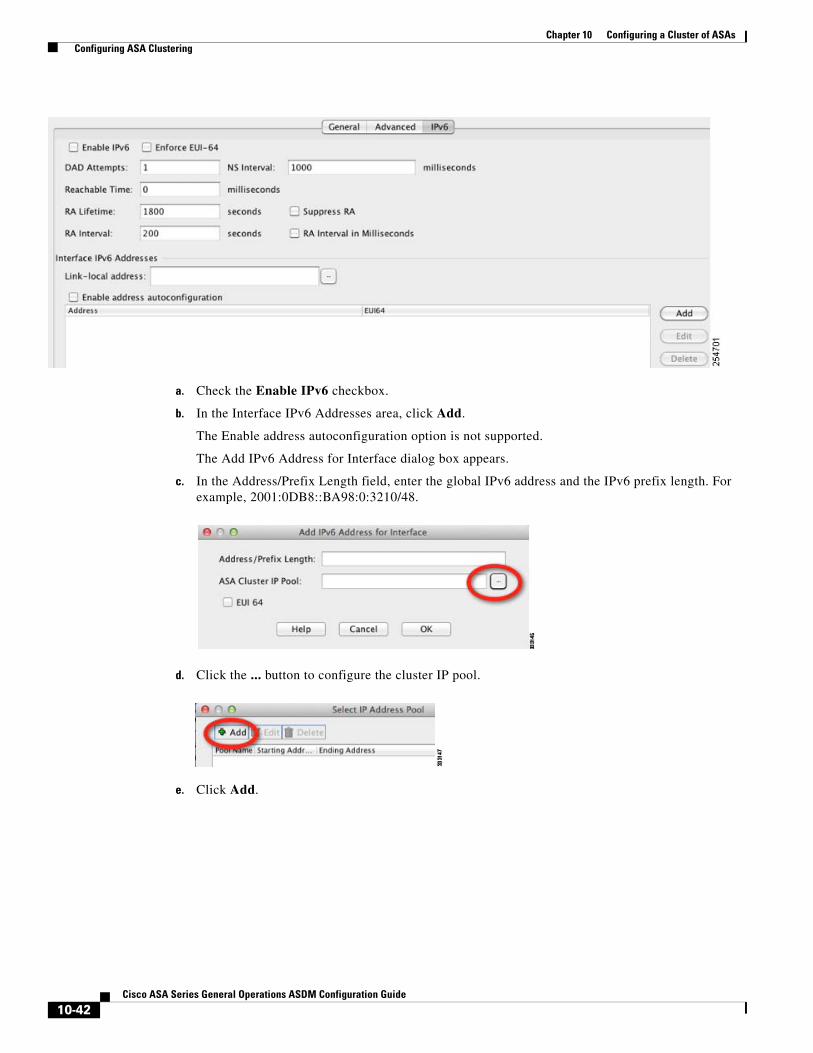
Chapter 10 Configuring a Cluster of ASAs Configuring ASA Clustering
a. Check the Enable IPv6 checkbox.
b. In the Interface IPv6 Addresses area, click Add.
The Enable address autoconfiguration option is not supported.
The Add IPv6 Address for Interface dialog box appears.
c. In the Address/Prefix Length field, enter the global IPv6 address and the IPv6 prefix length. For example, 2001:0DB8::BA98:0:3210/48.
d. Click the ... button to configure the cluster IP pool.
e. Click Add.
10-42Cisco ASA Series General Operations ASDM Configuration Guide

Chapter 10 Configuring a Cluster of ASAs Configuring ASA Clustering
f. Configure the starting IP address (network prefix), prefix length, and number of addresses in the pool.
g. Click OK to create the new pool.
h. Select the new pool you created, and click Assign, and then click OK.
The pool appears in the ASA Cluster IP Pool field.
i. Click OK.
j. For other optional parameters on the IPv6 tab, see the “Configuring IPv6 Addressing” section on page 13-15.
Step 5 Click OK to return to the Interfaces pane.
Step 6 Click Apply.
What to Do Next
• For spanned interface mode, configure your data interfaces. See the “Configuring Spanned EtherChannels” section on page 10-43.
• For Individual interface mode, join the cluster. See the “Adding or Joining an ASA Cluster” section on page 10-50.
Configuring Spanned EtherChannels
A Spanned EtherChannel spans all ASAs in the cluster, and provides load balancing as part of the EtherChannel operation.
Prerequisites
• You must be in Spanned EtherChannel interface mode; see the “Configuring the Cluster Interface Mode on the Master Unit” section on page 10-35.
• For multiple context mode, start this procedure in the system execution space. If you are not already in the System configuration mode in the Configuration > Device List pane, double-click System under the active device IP address.
• For transparent mode, configure the bridge group according to the “Configuring Bridge Groups” section on page 14-8.
10-43Cisco ASA Series General Operations ASDM Configuration Guide

Chapter 10 Configuring a Cluster of ASAs Configuring ASA Clustering
Guidelines
• Do not specify the maximum and minimum links in the EtherChannel—We recommend that you do not specify the maximum and minimum links in the EtherChannel on either the ASA or the switch. If you need to use them, note the following:
– The maximum links set on the ASA is the total number of active ports for the whole cluster. Be sure the maximum links value configured on the switch is not larger than the ASA value.
– The minimum links set on the ASA is the minimum active ports to bring up a port-channel interface per unit. On the switch, the minimum links is the minimum links across the cluster, so this value will not match the ASA value.
• Do not change the load-balancing algorithm from the default. On the switch, we recommend that you use one of the following algorithms: source-dest-ip or source-dest-ip-port (see the Nexus OS and IOS port-channel load-balance command). Do not use a vlan keyword in the load-balance algorithm because it can cause unevenly distributed traffic to the ASAs in a cluster.
• When using Spanned EtherChannels, the port-channel interface will not come up until clustering is fully enabled (see the “Adding or Joining an ASA Cluster” section on page 10-50). This requirement prevents traffic from being forwarded to a unit that is not an active unit in the cluster.
• For detailed EtherChannel guidelines, limitations, and prerequisites, see the “Configuring an EtherChannel” section on page 11-30.
• See also the “EtherChannel Guidelines” section on page 11-13.
Detailed Steps
Step 1 Depending on your context mode:
• For single mode, choose the Configuration > Device Setup > Interfaces pane.
• For multiple mode in the System execution space, choose the Configuration > Context Management > Interfaces pane.
Step 2 Choose Add > EtherChannel Interface.
The Add EtherChannel Interface dialog box appears.
10-44Cisco ASA Series General Operations ASDM Configuration Guide
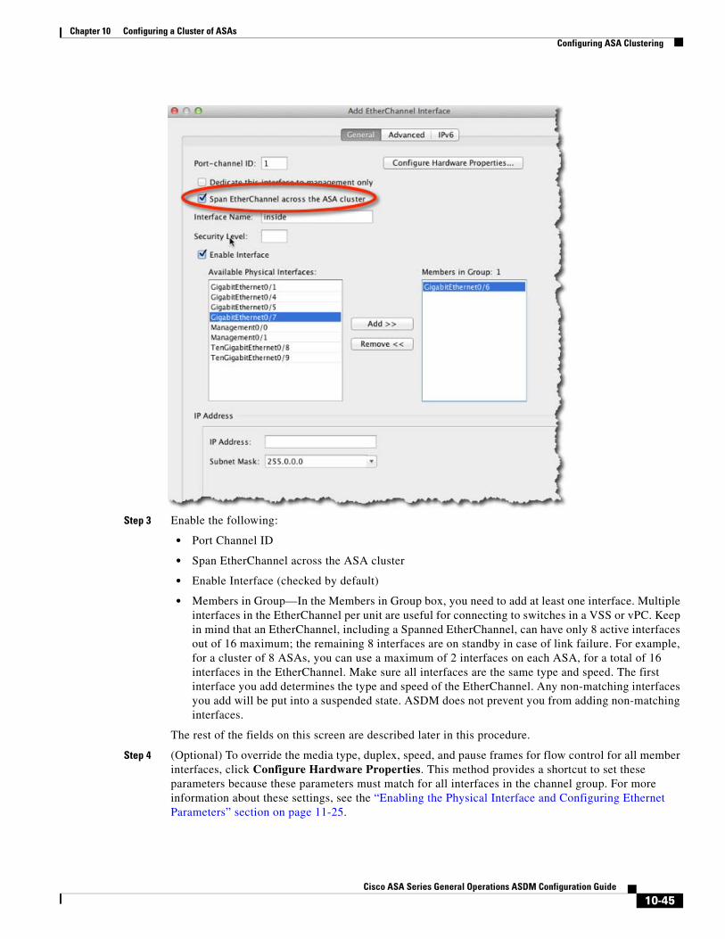
Chapter 10 Configuring a Cluster of ASAs Configuring ASA Clustering
Step 3 Enable the following:
• Port Channel ID
• Span EtherChannel across the ASA cluster
• Enable Interface (checked by default)
• Members in Group—In the Members in Group box, you need to add at least one interface. Multiple interfaces in the EtherChannel per unit are useful for connecting to switches in a VSS or vPC. Keep in mind that an EtherChannel, including a Spanned EtherChannel, can have only 8 active interfaces out of 16 maximum; the remaining 8 interfaces are on standby in case of link failure. For example, for a cluster of 8 ASAs, you can use a maximum of 2 interfaces on each ASA, for a total of 16 interfaces in the EtherChannel. Make sure all interfaces are the same type and speed. The first interface you add determines the type and speed of the EtherChannel. Any non-matching interfaces you add will be put into a suspended state. ASDM does not prevent you from adding non-matching interfaces.
The rest of the fields on this screen are described later in this procedure.
Step 4 (Optional) To override the media type, duplex, speed, and pause frames for flow control for all member interfaces, click Configure Hardware Properties. This method provides a shortcut to set these parameters because these parameters must match for all interfaces in the channel group. For more information about these settings, see the “Enabling the Physical Interface and Configuring Ethernet Parameters” section on page 11-25.
10-45Cisco ASA Series General Operations ASDM Configuration Guide

Chapter 10 Configuring a Cluster of ASAs Configuring ASA Clustering
Click OK to accept the Hardware Properties changes.
Step 5 (Optional) To configure the MAC address and optional parameters, click the Advanced tab.
10-46Cisco ASA Series General Operations ASDM Configuration Guide
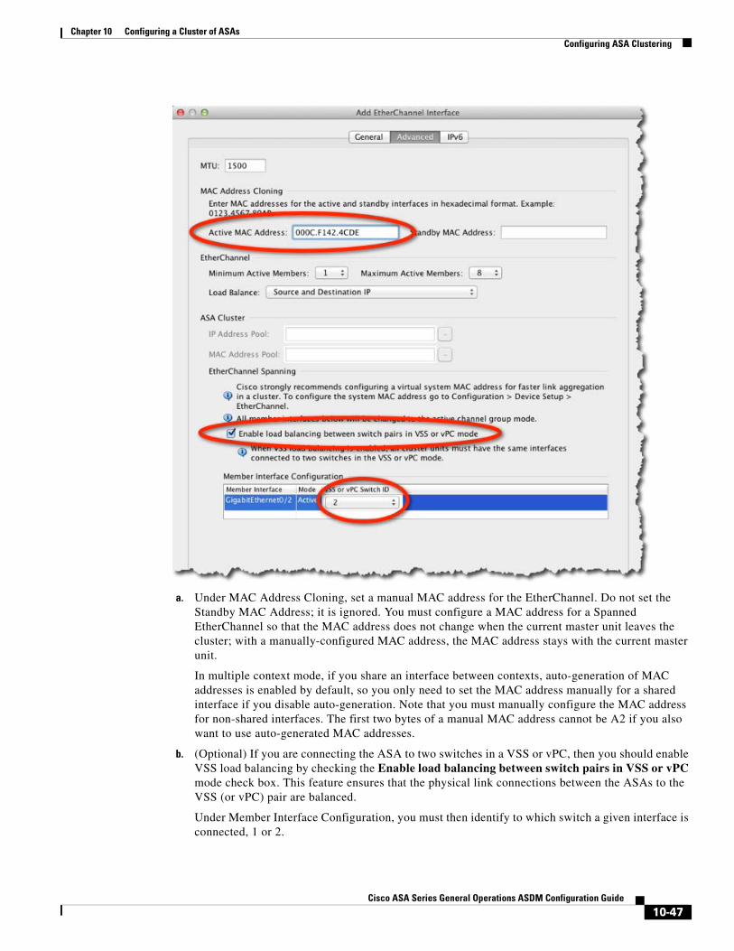
Chapter 10 Configuring a Cluster of ASAs Configuring ASA Clustering
a. Under MAC Address Cloning, set a manual MAC address for the EtherChannel. Do not set the Standby MAC Address; it is ignored. You must configure a MAC address for a Spanned EtherChannel so that the MAC address does not change when the current master unit leaves the cluster; with a manually-configured MAC address, the MAC address stays with the current master unit.
In multiple context mode, if you share an interface between contexts, auto-generation of MAC addresses is enabled by default, so you only need to set the MAC address manually for a shared interface if you disable auto-generation. Note that you must manually configure the MAC address for non-shared interfaces. The first two bytes of a manual MAC address cannot be A2 if you also want to use auto-generated MAC addresses.
b. (Optional) If you are connecting the ASA to two switches in a VSS or vPC, then you should enable VSS load balancing by checking the Enable load balancing between switch pairs in VSS or vPC mode check box. This feature ensures that the physical link connections between the ASAs to the VSS (or vPC) pair are balanced.
Under Member Interface Configuration, you must then identify to which switch a given interface is connected, 1 or 2.
10-47Cisco ASA Series General Operations ASDM Configuration Guide

Chapter 10 Configuring a Cluster of ASAs Configuring ASA Clustering
c. (Optional) For information about Load Balancing, see the “Configuring an EtherChannel” section on page 11-30. For information about the MTU, see the “Configuring the MAC Address, MTU, and TCP MSS” section on page 13-13.
We recommend that you do not set the Minimum Active Members and the Maximum Active Members. See the “Guidelines” section on page 10-44 for more information.
Step 6 (Optional) If you want to configure VLAN subinterfaces on this EtherChannel, see the “Configuring VLAN Subinterfaces and 802.1Q Trunking” section on page 11-36. The rest of this procedure applies to the subinterfaces.
Step 7 (Multiple context mode) Before you complete this procedure, you need to allocate interfaces to contexts.
a. Click OK to accept your changes.
b. To allocate interfaces, see the “Configuring a Security Context” section on page 8-20.
c. Change to the context you want to configure: in the Device List pane, double-click the context name under the active device IP address.
d. Choose the Configuration > Device Setup > Interfaces pane, select the port-channel interface you want to customize, and click Edit.
The Edit Interface dialog box appears.
Step 8 Click the General tab.
Step 9 (Transparent Mode) In the Bridge Group drop-down menu, choose the bridge group to which you want to assign this interface.
Step 10 In the Interface Name field, enter a name up to 48 characters in length.
Step 11 In the Security level field, enter a level between 0 (lowest) and 100 (highest). See the “Security Levels” section on page 13-1 for more information.
Step 12 (Routed Mode) For an IPv4 address, click the Use Static IP radio button and enter the IP address and mask. DHCP and PPPoE are not supported. For transparent mode, you configure the IP address for the bridge group interface, not the EtherChannel interface.
Step 13 (Optional) In the Description field, enter a description for this interface. The description can be up to 240 characters on a single line, without carriage returns.
Step 14 (Routed Mode) To configure an IPv6 address, click the IPv6 tab.
For transparent mode, you configure the IP address for the bridge group interface, not the EtherChannel interface.
a. Check the Enable IPv6 check box.
10-48Cisco ASA Series General Operations ASDM Configuration Guide

Chapter 10 Configuring a Cluster of ASAs Configuring ASA Clustering
b. In the Interface IPv6 Addresses area, click Add.
The Add IPv6 Address for Interface dialog box appears.
Note: The Enable address autoconfiguration option is not supported.
c. In the Address/Prefix Length field, enter the global IPv6 address and the IPv6 prefix length. For example, 2001:DB8::BA98:0:3210/64.
d. (Optional) To use the Modified EUI-64 interface ID as the host address, check the EUI-64 check box. In this case, just enter the prefix in the Address/Prefix Length field.
e. Click OK.
f. For other optional parameters on the IPv6 tab, see the “Configuring IPv6 Addressing” section on page 13-15.
Step 15 Click OK to return to the Interfaces screen.
Step 16 Click Apply.
What to Do Next
Join the cluster. See the “Adding or Joining an ASA Cluster” section on page 10-50.
10-49Cisco ASA Series General Operations ASDM Configuration Guide

Chapter 10 Configuring a Cluster of ASAs Configuring ASA Clustering
Adding or Joining an ASA ClusterEach unit in the cluster requires a bootstrap configuration to join the cluster. Run the High Availability and Scalability wizard on one unit (that will become the master unit) to create the cluster, and then add slave units to it. If you do not want to use the wizard, see the “Configuring ASA Cluster Parameters” section on page 10-59.
Note For the master unit, if you want to change the default of the cLACP system ID and priority, you cannot use the wizard; you must configure the cluster manually according to the “Configuring ASA Cluster Parameters” section on page 10-59.
Prerequisites
• For multiple context mode, complete this procedure in the system execution space. If you are not already in the System configuration mode, in the Configuration > Device List pane, double-click System under the active device IP address.
• We recommend enabling jumbo frame reservation for use with the cluster control link. See the “Enabling Jumbo Frame Support (Supported Models)” section on page 11-39.
• The interfaces you intend to use for the cluster control link interface must be in an up state on the connected switch.
• When you add a unit to a running cluster, you may see temporary, limited packet/connection drops; this is expected behavior.
• We suggest setting the cluster control link MTU to 1600 bytes or greater, which requires you to enable jumbo frame reservation on each unit before continuing with this procedure. See the “Enabling Jumbo Frame Support (Supported Models)” section on page 11-39. Jumbo frame reservation requires a reload of the ASA.
Detailed Steps 1—Starting the Wizard
Perform the following steps to start the High Availability and Scalability wizard.
Step 1 Choose Wizards > High Availability and Scalability Wizard.
Step 2 Click ASA Cluster, and then click Next.
10-50Cisco ASA Series General Operations ASDM Configuration Guide
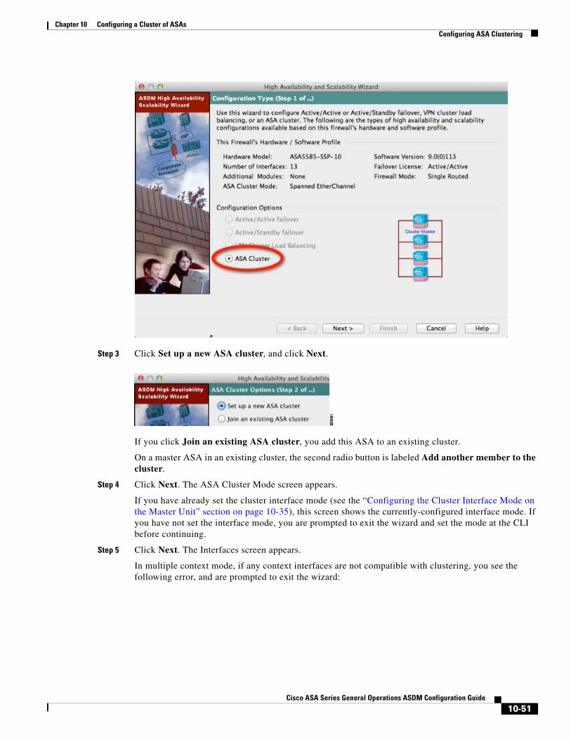
Chapter 10 Configuring a Cluster of ASAs Configuring ASA Clustering
Step 3 Click Set up a new ASA cluster, and click Next.
If you click Join an existing ASA cluster, you add this ASA to an existing cluster.
On a master ASA in an existing cluster, the second radio button is labeled Add another member to the cluster.
Step 4 Click Next. The ASA Cluster Mode screen appears.
If you have already set the cluster interface mode (see the “Configuring the Cluster Interface Mode on the Master Unit” section on page 10-35), this screen shows the currently-configured interface mode. If you have not set the interface mode, you are prompted to exit the wizard and set the mode at the CLI before continuing.
Step 5 Click Next. The Interfaces screen appears.
In multiple context mode, if any context interfaces are not compatible with clustering, you see the following error, and are prompted to exit the wizard:
10-51Cisco ASA Series General Operations ASDM Configuration Guide

Chapter 10 Configuring a Cluster of ASAs Configuring ASA Clustering
See the “(Recommended; Required in Multiple Context Mode) Configuring Interfaces on the Master Unit” section on page 10-38 to fix your interface configuration.
Detailed Steps 2—Configuring Interfaces
Step 1 Use this screen to configure the cluster control link. In single context mode, you can also use this screen to configure basic interface parameters. In multiple context mode, this screen only lets you configure hardware properties for interfaces.
Step 2 For the cluster control link, you can use a single interface, or add an EtherChannel from this dialog box.
To use a single interface:
a. Select the interface and click Edit.
b. Check the Enable Interface checkbox, and click OK.
10-52Cisco ASA Series General Operations ASDM Configuration Guide

Chapter 10 Configuring a Cluster of ASAs Configuring ASA Clustering
Make sure there is no name configured for the interface.
To add an EtherChannel for the cluster control link:
a. Click Add EtherChannel for Cluster Control Link.
The Add EtherChannel Interface for Cluster Control Link dialog box appears.
a. Specify the Port-channel ID.
b. Add member interfaces to the Members in Group window.
c. Click OK to return to the Interfaces dialog box.
d. Enable each EtherChannel member interface by selecting the interface and clicking Edit.
e. Check the Enable Interface checkbox, and click OK.
f. Repeat for other members.
Step 3 Make any other necessary interface changes; you cannot create new EtherChannels from this screen (except for the cluster control link). For more information about configuring interfaces for clustering, see the following sections:
• “Configuring Spanned EtherChannels” section on page 10-43
• “Configuring Individual Interfaces (Recommended for the Management Interface)” section on page 10-38
Step 4 Click Next.
The wizard verifies that all interfaces are cluster-ready. If you have any interfaces that are not cluster-ready, you see an error similar to the following:
10-53Cisco ASA Series General Operations ASDM Configuration Guide

Chapter 10 Configuring a Cluster of ASAs Configuring ASA Clustering
You are returned to the Interfaces screen to fix the interface configuration.
If your interface configuration passes the error checker, the ASA Cluster Configuration screen appears.
Detailed Steps 3—Configuring Bootstrap Settings
Step 1 Configure the following bootstrap settings:
a. Cluster Name—Names the cluster. The name must be an ASCII string from 1 to 38 characters. You can only configure one cluster per unit. All members of the cluster must use the same name.
10-54Cisco ASA Series General Operations ASDM Configuration Guide

Chapter 10 Configuring a Cluster of ASAs Configuring ASA Clustering
b. Member Name—Names this member of the cluster with a unique ASCII string from 1 to 38 characters.
c. Member Priority—Sets the priority of this unit for master unit elections, between 1 and 100, where 1 is the highest priority.
d. (Optional) Shared Key—Sets an encryption key for control traffic on the cluster control link. The shared secret is an ASCII string from 1 to 63 characters. The shared secret is used to generate the encryption key. This parameter does not affect datapath traffic, including connection state update and forwarded packets, which are always sent in the clear. You must configure this parameter if you also enable the password encryption service.
e. (Optional) Enable connection rebalancing for TCP traffic across all the ASAs in the cluster—Enables connection rebalancing. This parameter is disabled by default. If enabled, ASAs in a cluster exchange load information periodically, and offload new connections from more loaded devices to less loaded devices. The frequency, between 1 and 360 seconds, specifies how often the load information is exchanged. This parameter is not part of the bootstrap configuration, and is replicated from the master unit to the slave units.
Note Do not configure connection rebalancing for inter-site topologies; you do not want connections rebalanced to cluster members at a different site.
f. (Optional) Enable health monitoring of this device within the cluster—Enables the cluster health check feature, which includes unit heath monitoring and interface health monitoring. To determine unit health, the ASA cluster units send keepalive messages on the cluster control link to other units. If a unit does not receive any keepalive messages from a peer unit within the holdtime period, the peer unit is considered unresponsive or dead. The interface health check monitors for link failures. If an interface fails on a particular unit, but the same interface is active on other units, then the unit is removed from the cluster. If a unit does not receive interface status messages within the holdtime, then the amount of time before the ASA removes a member from the cluster depends on the type of interface and whether the unit is an established member or is joining the cluster. For details, see Interface monitoring, page 10-9.
Note When any topology changes occur (such as adding or removing a data interface, enabling or disabling an interface on the ASA or the switch, adding an additional switch to form a VSS or vPC) you must disable the health check. When the topology change is complete, and the configuration change is synced to all units, you can re-enable the health check.
– Time to Wait Before Device Considered Failed—This value determines the amount of time between unit keepalive status messages, between .8 and 45 seconds; The default is 3 seconds. Note that the holdtime value only affects the unit health check; for interface health, the ASA uses the interface status (up or down).
– (Optional) Broadcast keepalive messages to all EtherChannel cluster control link ports for VSS/vPC support—If you configure the cluster control link as an EtherChannel (recommended), and it is connected to a VSS or vPC pair, then you might need to enable this option. For some switches, when one unit in the VSS/vPC is shutting down or booting up, EtherChannel member interfaces connected to that switch may appear to be Up to the ASA, but they are not passing traffic on the switch side. The ASA can be erroneously removed from the cluster if you set the ASA holdtime timeout to a low value (such as .8 seconds), and the ASA sends keepalive messages on one of these EtherChannel interfaces. When you enable this option, the ASA floods the keepalive messages on all EtherChannel interfaces in the cluster control link to ensure that at least one of the switches can receive them.
10-55Cisco ASA Series General Operations ASDM Configuration Guide

Chapter 10 Configuring a Cluster of ASAs Configuring ASA Clustering
g. (Optional) Replicate console output to the master’s console—Enables console replication from slave units to the master unit. This feature is disabled by default. The ASA may print out some messages directly to the console for certain critical events. If you enable console replication, slave units send the console messages to the master unit so you only need to monitor one console port for the cluster. This parameter is not part of the bootstrap configuration, and is replicated from the master unit to the slave units.
h. Cluster Control Link—Specifies the cluster control link interface. This interface cannot have a name configured; available interfaces are shown in the drop-down list.
– Interface—Specifies the interface ID, preferably an EtherChannel. Subinterfaces and Management type interfaces are not allowed.
– IP Address—Specifies an IPv4 address for the IP address; IPv6 is not supported for this interface.
– Subnet Mask—Specifies the subnet mask.
– (Optional) MTU—Specifies the maximum transmission unit for the cluster control link interface, between 64 and 65,535 bytes. Data that is larger than the MTU value is fragmented before being sent. The default MTU is 1500 bytes. If you already enabled jumbo frame reservation, we suggest setting the MTU to 1600 bytes or greater. If you want to use jumbo frames and have not pre-enabled jumbo frame reservation, you should quit the wizard, enable jumbo frames, and then restart this procedure. See the “Enabling Jumbo Frame Support (Supported Models)” section on page 11-39.
Step 2 Click Next.
The wizard shows the cluster configuration.
Step 3 Click Finish.
Step 4 The ASA scans the running configuration for incompatible commands for features that are not supported with clustering, including commands that may be present in the default configuration. Click OK to delete the incompatible commands. If you click Cancel, then clustering is not enabled.
10-56Cisco ASA Series General Operations ASDM Configuration Guide

Chapter 10 Configuring a Cluster of ASAs Configuring ASA Clustering
Step 5 After a period of time while ASDM enables clustering and reconnects to the ASA, the Information screen appears confirming that the ASA was added to the cluster.
Note In some cases, there might be an error when joining the cluster after you finish the wizard. If ASDM was disconnected, ASDM will not receive any subsequent errors from the ASA. If clustering remains disabled after you reconnect ASDM, you should connect to the ASA console port to determine the exact error condition that disabled clustering; for example, the cluster control link might be down.
Detailed Steps 4—Adding Slave Units
Step 1 To add a slave unit, click Yes.
If you are re-running the wizard from the master, you can add slave units by choosing the Add another member to the cluster option when you first start the wizard.
10-57Cisco ASA Series General Operations ASDM Configuration Guide

Chapter 10 Configuring a Cluster of ASAs Configuring ASA Clustering
Step 2 Set the new member name, priority, and cluster control link IP address (on the same network as the other units’ cluster control links).
Step 3 Under Deployment Options, choose one of the following Deploy By options:
• Sending CLI commands to the remote unit now—Send the bootstrap configuration to the slave (temporary) management IP address. Enter the slave management IP address, username, and password.
• Copying generated CLI commands to paste on the remote unit manually—Generates the commands so you can cut and paste them at the slave unit CLI or using the CLI tool in ASDM. In the Commands to Deploy box, select and copy the generated commands for later use.
Step 4 Click Next. After a validation, the Summary screen appears. Click Finish.
10-58Cisco ASA Series General Operations ASDM Configuration Guide
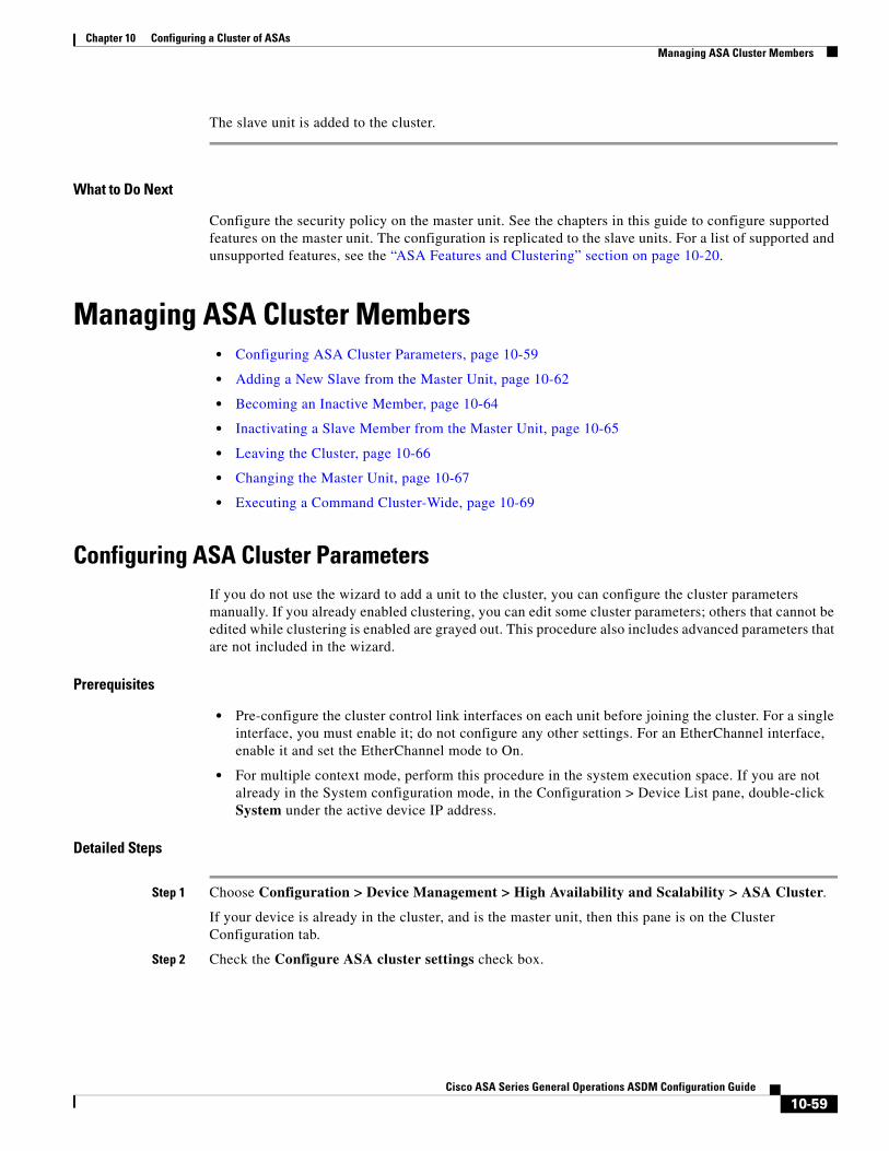
Chapter 10 Configuring a Cluster of ASAs Managing ASA Cluster Members
The slave unit is added to the cluster.
What to Do Next
Configure the security policy on the master unit. See the chapters in this guide to configure supported features on the master unit. The configuration is replicated to the slave units. For a list of supported and unsupported features, see the “ASA Features and Clustering” section on page 10-20.
Managing ASA Cluster Members• Configuring ASA Cluster Parameters, page 10-59
• Adding a New Slave from the Master Unit, page 10-62
• Becoming an Inactive Member, page 10-64
• Inactivating a Slave Member from the Master Unit, page 10-65
• Leaving the Cluster, page 10-66
• Changing the Master Unit, page 10-67
• Executing a Command Cluster-Wide, page 10-69
Configuring ASA Cluster ParametersIf you do not use the wizard to add a unit to the cluster, you can configure the cluster parameters manually. If you already enabled clustering, you can edit some cluster parameters; others that cannot be edited while clustering is enabled are grayed out. This procedure also includes advanced parameters that are not included in the wizard.
Prerequisites
• Pre-configure the cluster control link interfaces on each unit before joining the cluster. For a single interface, you must enable it; do not configure any other settings. For an EtherChannel interface, enable it and set the EtherChannel mode to On.
• For multiple context mode, perform this procedure in the system execution space. If you are not already in the System configuration mode, in the Configuration > Device List pane, double-click System under the active device IP address.
Detailed Steps
Step 1 Choose Configuration > Device Management > High Availability and Scalability > ASA Cluster.
If your device is already in the cluster, and is the master unit, then this pane is on the Cluster Configuration tab.
Step 2 Check the Configure ASA cluster settings check box.
10-59Cisco ASA Series General Operations ASDM Configuration Guide
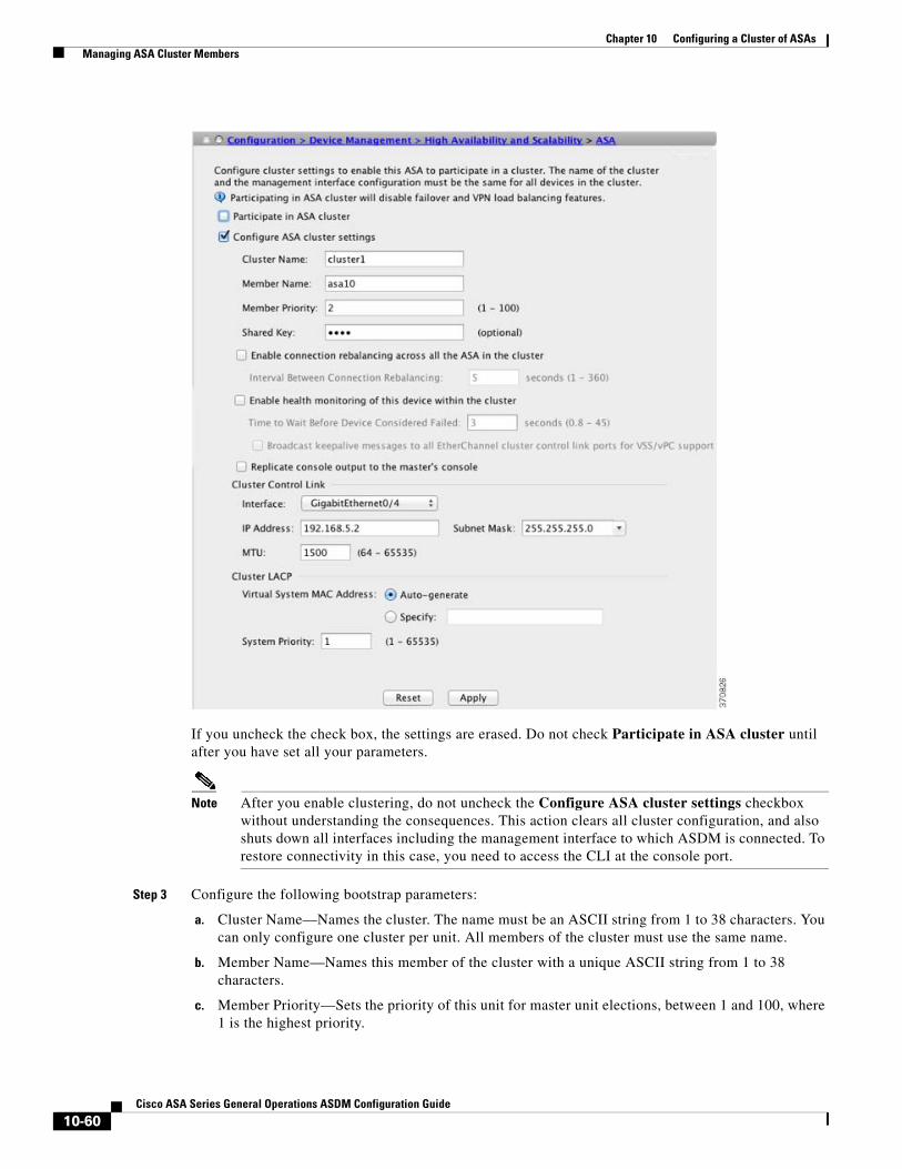
Chapter 10 Configuring a Cluster of ASAs Managing ASA Cluster Members
If you uncheck the check box, the settings are erased. Do not check Participate in ASA cluster until after you have set all your parameters.
Note After you enable clustering, do not uncheck the Configure ASA cluster settings checkbox without understanding the consequences. This action clears all cluster configuration, and also shuts down all interfaces including the management interface to which ASDM is connected. To restore connectivity in this case, you need to access the CLI at the console port.
Step 3 Configure the following bootstrap parameters:
a. Cluster Name—Names the cluster. The name must be an ASCII string from 1 to 38 characters. You can only configure one cluster per unit. All members of the cluster must use the same name.
b. Member Name—Names this member of the cluster with a unique ASCII string from 1 to 38 characters.
c. Member Priority—Sets the priority of this unit for master unit elections, between 1 and 100, where 1 is the highest priority.
10-60Cisco ASA Series General Operations ASDM Configuration Guide

Chapter 10 Configuring a Cluster of ASAs Managing ASA Cluster Members
d. (Optional) Shared Key—Sets an encryption key for control traffic on the cluster control link. The shared secret is an ASCII string from 1 to 63 characters. The shared secret is used to generate the encryption key. This parameter does not affect datapath traffic, including connection state update and forwarded packets, which are always sent in the clear. You must configure this parameter if you also enable the password encryption service.
e. (Optional) Enable connection rebalancing for TCP traffic across all the ASAs in the cluster—Enables connection rebalancing. This parameter is disabled by default. If enabled, ASAs in a cluster exchange load information periodically, and offload new connections from more loaded devices to less loaded devices. The frequency, between 1 and 360 seconds, specifies how often the load information is exchanged. This parameter is not part of the bootstrap configuration, and is replicated from the master unit to the slave units.
f. (Optional) Enable health monitoring of this device within the cluster—Enables the cluster health check feature, which includes unit heath monitoring and interface health monitoring. Note: When you are adding new units to the cluster, and making topology changes on the ASA or the switch, you should disable this feature temporarily until the cluster is complete. You can re-enable this feature after cluster and topology changes are complete. To determine unit health, the ASA cluster units send keepalive messages on the cluster control link to other units. If a unit does not receive any keepalive messages from a peer unit within the holdtime period, the peer unit is considered unresponsive or dead. Interface status messages detect link failure. If an interface fails on a particular unit, but the same interface is active on other units, then the unit is removed from the cluster. If a unit does not receive interface status messages within the holdtime, then the amount of time before the ASA removes a member from the cluster depends on the type of interface and whether the unit is an established member or is joining the cluster. For details, see Interface monitoring, page 10-9.
Note When any topology changes occur (such as adding or removing a data interface, enabling or disabling an interface on the ASA or the switch, adding an additional switch to form a VSS or vPC) you must disable the health check. When the topology change is complete, and the configuration change is synced to all units, you can re-enable the health check.
– (Optional) Broadcast keepalive messages to all EtherChannel cluster control link ports for VSS/vPC support—If you configure the cluster control link as an EtherChannel (recommended), and it is connected to a VSS or vPC pair, then you might need to enable this option. For some switches, when one unit in the VSS/vPC is shutting down or booting up, EtherChannel member interfaces connected to that switch may appear to be Up to the ASA, but they are not passing traffic on the switch side. The ASA can be erroneously removed from the cluster if you set the ASA holdtime timeout to a low value (such as .8 seconds), and the ASA sends keepalive messages on one of these EtherChannel interfaces. When you enable this option, the ASA floods the keepalive messages on all EtherChannel interfaces in the cluster control link to ensure that at least one of the switches can receive them.
g. (Optional) Replicate console output to the master’s console—Enables console replication from slave units to the master unit. This feature is disabled by default. The ASA may print out some messages directly to the console for certain critical events. If you enable console replication, slave units send the console messages to the master unit so you only need to monitor one console port for the cluster. This parameter is not part of the bootstrap configuration, and is replicated from the master unit to the slave units.
h. Cluster Control Link—Specifies the cluster control link interface. This interface cannot have a name configured; available interfaces are shown in the drop-down list.
– Interface—Specifies the interface ID, preferably an EtherChannel. Subinterfaces and Management type interfaces are not allowed.
10-61Cisco ASA Series General Operations ASDM Configuration Guide

Chapter 10 Configuring a Cluster of ASAs Managing ASA Cluster Members
– IP Address—Specifies an IPv4 address for the IP address; IPv6 is not supported for this interface.
– Subnet Mask—Specifies the subnet mask.
– (Optional) MTU—Specifies the maximum transmission unit for the cluster control link interface, between 64 and 65,535 bytes. Data that is larger than the MTU value is fragmented before being sent. The default MTU is 1500 bytes. We suggest setting the MTU to 1600 bytes or greater, which requires you to enable jumbo frame reservation. See the “Enabling Jumbo Frame Support (Supported Models)” section on page 11-39.
i. (Optional) Cluster LACP—When using Spanned EtherChannels, the ASA uses cLACP to negotiate the EtherChannel with the neighbor switch. ASAs in a cluster collaborate in cLACP negotiation so that they appear as a single (virtual) device to the switch.
– Virtual System MAC Address—Sets the cLACP system ID, which is in the format of a MAC address. All ASAs use the same system ID: auto-generated by the master unit (the default) and replicated to all slaves; or manually specified in the form H.H.H, where H is a 16-bit hexadecimal digit. For example, the MAC address 00-0C-F1-42-4C-DE is entered as 000C.F142.4CDE. This parameter is not part of the bootstrap configuration, and is replicated from the master unit to the slave units. However, you cannot change this value after you enable clustering.
– System Priority—Sets the system priority, between 1 and 65535. The priority is used to decide which unit is in charge of making a bundling decision. By default, the ASA uses priority 1, which is the highest priority. The priority needs to be higher than the priority on the switch. This parameter is not part of the bootstrap configuration, and is replicated from the master unit to the slave units. However, you cannot change this value after you enable clustering.
Step 4 Check the Participate in ASA cluster check box to join the cluster.
Step 5 Click Apply.
Adding a New Slave from the Master UnitYou can add additional slaves to the cluster from the master unit. You can also add slaves using the High Availability and Scalability wizard. Adding a slave from the master unit has the benefit of configuring the cluster control link and setting the cluster interface mode on each slave unit you add.
You can alternatively log into the slave unit and configure clustering on the unit according to the “Configuring ASA Cluster Parameters” section on page 10-59. However, after you enable clustering, your ASDM session will be disconnected, and you will have to reconnect.
Prerequisites
• For multiple context mode, complete this procedure in the system execution space. If you are not already in the System configuration mode, in the Configuration > Device List pane, double-click System under the active device IP address.
• If you want to send the bootstrap configuration over the management network, be sure the slave unit has an accessible IP address.
10-62Cisco ASA Series General Operations ASDM Configuration Guide

Chapter 10 Configuring a Cluster of ASAs Managing ASA Cluster Members
Detailed Steps
Step 1 Choose Configuration > Device Management > High Availability and Scalability > ASA Cluster > Cluster Members.
Step 2 Click Add.
Step 3 Configure the following parameters:
a. Member Name—Names this member of the cluster with a unique ASCII string from 1 to 38 characters.
b. Member Priority—Sets the priority of this unit for master unit elections, between 1 and 100, where 1 is the highest priority.
c. Cluster Control Link > IP Address—Specifies a unique IP address for this member for the cluster control link, on the same network as the master cluster control link.
d. Under Deployment Options, choose one of the following Deploy By options:
– Sending CLI commands to the remote unit now—Send the bootstrap configuration to the slave (temporary) management IP address. Enter the slave management IP address, username, and password.
10-63Cisco ASA Series General Operations ASDM Configuration Guide

Chapter 10 Configuring a Cluster of ASAs Managing ASA Cluster Members
– Copying generated CLI commands to paste on the remote unit manually—Generates the commands so you can cut and paste them at the slave unit CLI or using the CLI tool in ASDM. In the Commands to Deploy box, select and copy the generated commands for later use.
Step 4 Click OK, then Apply.
Becoming an Inactive MemberTo become an inactive member of the cluster, disable clustering on the unit while leaving the clustering configuration intact.
Note When an ASA becomes inactive (either manually or through a health check failure), all data interfaces are shut down; only the management-only interface can send and receive traffic. To resume traffic flow, re-enable clustering; or you can remove the unit altogether from the cluster. See the “Leaving the Cluster” section on page 10-66. The management interface remains up using the IP address the unit received from the cluster IP pool. However if you reload, and the unit is still inactive in the cluster, the management interface is not accessible (because it then uses the Main IP address, which is the same as the master unit). You must use the console port for any further configuration.
Prerequisites
• For multiple context mode, perform this procedure in the system execution space. If you are not already in the System configuration mode in the Configuration > Device List pane, double-click System under the active device IP address.
Detailed Steps
Step 1 Choose Configuration > Device Management > High Availability and Scalability > ASA Cluster.
If your device is already in the cluster, and is the master unit, then this pane is on the Cluster Configuration tab.
Step 2 Uncheck the Participate in ASA cluster check box.
10-64Cisco ASA Series General Operations ASDM Configuration Guide

Chapter 10 Configuring a Cluster of ASAs Managing ASA Cluster Members
Note Do not uncheck the Configure ASA cluster settings checkbox; this action clears all cluster configuration, and also shuts down all interfaces including the management interface to which ASDM is connected. To restore connectivity in this case, you need to access the CLI at the console port.
Step 3 Click Apply.
If this unit was the master unit, a new master election takes place, and a different member becomes the master unit.
The cluster configuration is maintained, so you can enable clustering again later.
Inactivating a Slave Member from the Master UnitTo inactivate a slave member, perform the following steps.
10-65Cisco ASA Series General Operations ASDM Configuration Guide

Chapter 10 Configuring a Cluster of ASAs Managing ASA Cluster Members
Note When an ASA becomes inactive, all data interfaces are shut down; only the management-only interface can send and receive traffic. To resume traffic flow, re-enable clustering; or you can remove the unit altogether from the cluster. See the “Leaving the Cluster” section on page 10-66. The management interface remains up using the IP address the unit received from the cluster IP pool. However if you reload, and the unit is still inactive in the cluster, the management interface is not accessible (because it then uses the Main IP address, which is the same as the master unit). You must use the console port for any further configuration.
Prerequisites
For multiple context mode, perform this procedure in the system execution space. If you are not already in the System configuration mode in the Configuration > Device List pane, double-click System under the active device IP address.
Detailed Steps
Step 1 Choose Configuration > Device Management > High Availability and Scalability > ASA Cluster.
Step 2 Select the slave you want to remove, and click Delete.
The slave bootstrap configuration remains intact, so you can later re-add the slave without losing your configuration.
Step 3 Click Apply.
Leaving the ClusterIf you want to leave the cluster altogether, you need to remove the entire cluster bootstrap configuration. Because the current configuration on each member is the same (synced from the master unit), leaving the cluster also means either restoring a pre-clustering configuration from backup, or clearing your configuration and starting over to avoid IP address conflicts.
Prerequisites
You must use the console port; when you remove the cluster configuration, all interfaces are shut down, including the management interface and cluster control link.
10-66Cisco ASA Series General Operations ASDM Configuration Guide

Chapter 10 Configuring a Cluster of ASAs Managing ASA Cluster Members
Detailed Steps
Changing the Master Unit
Caution The best method to change the master unit is to disable clustering on the master unit (see the “Becoming an Inactive Member” section on page 10-64), waiting for a new master election, and then re-enabling clustering. If you must specify the exact unit you want to become the master, use the procedure in this section. Note, however, that for centralized features, if you force a master unit change using this procedure, then all connections are dropped, and you have to re-establish the connections on the new master unit. See the “Centralized Features” section on page 10-21 for a list of centralized features.
Command Purpose
Step 1 For a slave unit:
cluster group cluster_nameno enable
Example:ciscoasa(config)# cluster group cluster1ciscoasa(cfg-cluster)# no enable
Disables clustering. You cannot make configuration changes while clustering is enabled on a slave unit.
Step 2 clear configure cluster
Example:ciscoasa(config)# clear configure cluster
Clears the cluster configuration. The ASA shuts down all interfaces including the management interface and cluster control link.
Step 3 no cluster interface-mode
Example:ciscoasa(config)# no cluster interface-mode
Disables cluster interface mode. The mode is not stored in the configuration and must be reset manually.
Step 4 If you have a backup configuration:
copy backup_cfg running-config
Example:ciscoasa(config)# copy backup_cluster.cfg running-config
Source filename [backup_cluster.cfg]?
Destination filename [running-config]?ciscoasa(config)#
Copies the backup configuration to the running configuration.
Step 5 write memory
Example:ciscoasa(config)# write memory
Saves the configuration to startup.
Step 6 If you do not have a backup configuration, reconfigure management access according to Chapter 3, “Getting Started.” Be sure to change the interface IP addresses, and restore the correct hostname, for example.
10-67Cisco ASA Series General Operations ASDM Configuration Guide

Chapter 10 Configuring a Cluster of ASAs Managing ASA Cluster Members
To change the master unit, perform the following steps.
Prerequisites
For multiple context mode, perform this procedure in the system execution space. If you are not already in the System configuration mode in the Configuration > Device List pane, double-click System under the active device IP address.
Detailed Steps
Step 1 Choose Monitoring > ASA Cluster > Cluster Summary.
Step 2 In the Change Master To drop-down menu, choose a slave unit to become master, and click Make Master.
Step 3 You are prompted to confirm the master unit change. Click Yes.
10-68Cisco ASA Series General Operations ASDM Configuration Guide

Chapter 10 Configuring a Cluster of ASAs Managing ASA Cluster Members
Step 4 Quit ASDM, and reconnect using the Main cluster IP address.
Executing a Command Cluster-WideTo send a command to all members in the cluster, or to a specific member, perform the following steps. Sending a show command to all members collects all output and displays it on the console of the current unit. Other commands, such as capture and copy, can also take advantage of cluster-wide execution.
Detailed Steps
Step 1 Choose Tools > Command Line Interface.
Step 2 Enter the following command:
Step 3 Click Send.
Examples
To copy the same capture file from all units in the cluster at the same time to a TFTP server, enter the following command on the master unit:
cluster exec copy /pcap capture: tftp://10.1.1.56/capture1.pcap
Multiple PCAP files, one from each unit, are copied to the TFTP server. The destination capture file name is automatically attached with the unit name, such as capture1_asa1.pcap, capture1_asa2.pcap, and so on. In this example, asa1 and asa2 are cluster unit names.
The following sample output for the cluster exec show port-channel summary command shows EtherChannel information for each member in the cluster:
cluster exec show port-channel summaryprimary(LOCAL):*********************************************************** Number of channel-groups in use: 2Group Port-channel Protocol Span-cluster Ports
Command Purpose
cluster exec [unit unit_name] command
Example:ciscoasa# cluster exec show xlate
Sends a command to all members, or if you specify the unit name, a specific member.
To view member names, enter cluster exec unit ? (to see all names except the current unit), or enter the show cluster info command.
10-69Cisco ASA Series General Operations ASDM Configuration Guide

Chapter 10 Configuring a Cluster of ASAs Monitoring the ASA Cluster
------+-------------+-----------+-----------------------------------------------1 Po1 LACP Yes Gi0/0(P)2 Po2 LACP Yes Gi0/1(P) secondary:****************************************************************** Number of channel-groups in use: 2Group Port-channel Protocol Span-cluster Ports------+-------------+-----------+-----------------------------------------------1 Po1 LACP Yes Gi0/0(P)2 Po2 LACP Yes Gi0/1(P)
Monitoring the ASA Cluster• Cluster Dashboards, page 10-70
• Monitoring Screens, page 10-70
• Related Features, page 10-72
Cluster DashboardsOn the Home page on the master unit, you can monitor the cluster using the Cluster Dashboard and the Cluster Firewall Dashboard. For more information, see the “Cluster Dashboard Tab” section on page 4-25 and the “Cluster Firewall Dashboard Tab” section on page 4-26.
Monitoring Screens• Viewing the Cluster Summary, page 10-70
• Monitoring Cluster Resources, page 10-71
• Monitoring Cluster Traffic, page 10-71
• Monitoring the Cluster Control Link, page 10-72
Viewing the Cluster Summary
Choose Monitoring > ASA Cluster > Cluster Summary. This pane shows cluster information about the unit to which you are connected, as well as other units in the cluster. You can also change the master unit from this pane.
10-70Cisco ASA Series General Operations ASDM Configuration Guide

Chapter 10 Configuring a Cluster of ASAs Monitoring the ASA Cluster
Monitoring Cluster Resources
CPU
Choose Monitoring > ASA Cluster > System Resources Graphs > CPU. This pane lets you create graphs or tables showing the CPU utilization across the cluster members.
Memory
Choose Monitoring > ASA Cluster > System Resources Graphs > Memory. This pane lets you create graphs or tables showing the Free Memory and Used Memory across the cluster members.
Monitoring Cluster Traffic
Connections
Choose Monitoring > ASA Cluster > Traffic Graphs > Connections. This pane lets you create graphs or tables showing the Connections across the cluster members.
10-71Cisco ASA Series General Operations ASDM Configuration Guide

Chapter 10 Configuring a Cluster of ASAs Configuration Examples for ASA Clustering
Throughput
Choose Monitoring > ASA Cluster > Traffic Graphs > Throughput. This pane lets you create graphs or tables showing the traffic throughput across the cluster members.
Monitoring the Cluster Control Link
Choose Monitoring > Properties > System Resources Graphs > Cluster Control Link. This pane lets you create graphs or tables showing the cluster control link Receival and Transmittal capacity utilization.
Related Features
Configuration Examples for ASA Clustering• Sample ASA and Switch Configuration, page 10-72
• Firewall on a Stick, page 10-75
• Traffic Segregation, page 10-77
• Redundant Interface (PBR or ECMP), page 10-80
• Spanned EtherChannel With Backup Links, page 10-82
Sample ASA and Switch ConfigurationThe following sample configurations connect the following interfaces between the ASA and the switch:
Command Purpose
Wizards > Packet Capture Wizard To support cluster-wide troubleshooting, you can enable capture of cluster-specific traffic on the master unit, which is then automatically enabled on all of the slave units in the cluster.
See the “Configuring and Running Captures with the Packet Capture Wizard” section on page 47-1.
Configuration > Device Management > Interfaces > Edit Interface > Advanced
Creates a MAC address pool for an individual interface.
Configuration > Device Management > Management Access > Command Line (CLI) > CLI Prompt
Sets the CLI prompt to include the cluster unit name.
See the “Customizing a CLI Prompt” section on page 45-7.
Configuration > Device Management > Logging > Syslog Setup
Each unit in the cluster generates syslog messages independently. You can generate syslog messages with identical or different device IDs to make messages appear to come from the same or different units in the cluster.
See the “Including the Device ID in Non-EMBLEM Format Syslog Messages” section on page 41-22.
10-72Cisco ASA Series General Operations ASDM Configuration Guide

Chapter 10 Configuring a Cluster of ASAs Configuration Examples for ASA Clustering
• ASA Configuration, page 10-73
• IOS Switch Configuration, page 10-74
ASA Configuration
Interface Mode on Each Unitcluster interface-mode spanned force
ASA1 Master Bootstrap Configurationinterface GigabitEthernet0/0 channel-group 1 mode onno shutdown
!interface GigabitEthernet0/1 channel-group 1 mode onno shutdown
!interface Port-channel1description Clustering Interface
!cluster group Moya local-unit A cluster-interface Port-channel1 ip 10.0.0.1 255.255.255.0 priority 10key emphyri0enable noconfirm
ASA2 Slave Bootstrap Configurationinterface GigabitEthernet0/0 channel-group 1 mode onno shutdown
!interface GigabitEthernet0/1 channel-group 1 mode onno shutdown
!interface Port-channel1description Clustering Interface
!cluster group Moya local-unit B cluster-interface Port-channel1 ip 10.0.0.2 255.255.255.0 priority 11key emphyri0enable as-slave
ASA Interface Switch Interface
GigabitEthernet 0/2 GigabitEthernet 1/0/15
GigabitEthernet 0/3 GigabitEthernet 1/0/16
GigabitEthernet 0/4 GigabitEthernet 1/0/17
GigabitEthernet 0/5 GigabitEthernet 1/0/18
10-73Cisco ASA Series General Operations ASDM Configuration Guide

Chapter 10 Configuring a Cluster of ASAs Configuration Examples for ASA Clustering
Master Interface Configurationip local pool mgmt-pool 10.53.195.231-10.53.195.232
interface GigabitEthernet0/2 channel-group 10 mode activeno shutdown
!interface GigabitEthernet0/3 channel-group 10 mode activeno shutdown
!interface GigabitEthernet0/4 channel-group 11 mode activeno shutdown
!interface GigabitEthernet0/5 channel-group 11 mode activeno shutdown
!interface Management0/0 management-onlynameif managementip address 10.53.195.230 cluster-pool mgmt-poolsecurity-level 100no shutdown
!interface Port-channel10 port-channel span-cluster mac-address aaaa.bbbb.cccc nameif inside security-level 100 ip address 209.165.200.225 255.255.255.224!interface Port-channel11 port-channel span-cluster mac-address aaaa.dddd.cccc nameif outside security-level 0 ip address 209.165.201.1 255.255.255.224
IOS Switch Configuration
interface GigabitEthernet1/0/15 switchport access vlan 201 switchport mode access spanning-tree portfast channel-group 10 mode active!interface GigabitEthernet1/0/16 switchport access vlan 201 switchport mode access spanning-tree portfast channel-group 10 mode active!interface GigabitEthernet1/0/17 switchport access vlan 401 switchport mode access spanning-tree portfast channel-group 11 mode active!interface GigabitEthernet1/0/18
10-74Cisco ASA Series General Operations ASDM Configuration Guide

Chapter 10 Configuring a Cluster of ASAs Configuration Examples for ASA Clustering
switchport access vlan 401 switchport mode access spanning-tree portfast channel-group 11 mode active
interface Port-channel10 switchport access vlan 201 switchport mode access
interface Port-channel11 switchport access vlan 401 switchport mode access
Firewall on a Stick
Data traffic from different security domains are associated with different VLANs, for example, VLAN 10 for the inside network and VLAN 20 for the outside network. Each ASA has a single physical port connected to the external switch or router. Trunking is enabled so that all packets on the physical link are 802.1q encapsulated. The ASA is the firewall between VLAN 10 and VLAN 20.
When using Spanned EtherChannels, all data links are grouped into one EtherChannel on the switch side. If an ASA becomes unavailable, the switch will rebalance traffic between the remaining units.
ASA1
3332
21
ten0
/8
ten0
/9
man
0/0
ASA2
ten0
/8
ten0
/9
man
0/0
ASA3
ten0
/8
ten0
/9
man
0/0
Switch
management10.1.1.1/24 (Pool: .2-.9),2001:DB8::1002/64(Pool: 8 IPs)
Cluster Control Link192.168.1.1, .2, and .3
port-ch5VLAN 10, VLAN 20 Trunk
VLA
N 1
0
VLA
N 2
0
Client Server
port-ch1 Spannedport-ch1.10 inside VLAN 10 10.10.10.5/24, 2001:DB8:2::5/64
MAC: 000C.F142.4CDEport-ch1.20 outside VLAN 20 209.165.201.5/27, 2001:DB8:2::5/64
MAC: 000C.F142.5CDE
10-75Cisco ASA Series General Operations ASDM Configuration Guide

Chapter 10 Configuring a Cluster of ASAs Configuration Examples for ASA Clustering
Interface Mode on Each Unitcluster interface-mode spanned force
ASA1 Master Bootstrap Configurationinterface tengigabitethernet 0/8
no shutdowndescription CCL
cluster group cluster1local-unit asa1cluster-interface tengigabitethernet0/8 ip 192.168.1.1 255.255.255.0priority 1key chuntheunavoidableenable noconfirm
ASA2 Slave Bootstrap Configurationinterface tengigabitethernet 0/8
no shutdowndescription CCL
cluster group cluster1local-unit asa2cluster-interface tengigabitethernet0/8 ip 192.168.1.2 255.255.255.0priority 2key chuntheunavoidableenable as-slave
ASA3 Slave Bootstrap Configurationinterface tengigabitethernet 0/8
no shutdowndescription CCL
cluster group cluster1local-unit asa3cluster-interface tengigabitethernet0/8 ip 192.168.1.3 255.255.255.0priority 3key chuntheunavoidableenable as-slave
Master Interface Configurationip local pool mgmt 10.1.1.2-10.1.1.9ipv6 local pool mgmtipv6 2001:DB8::1002/64 8
interface management 0/0nameif managementip address 10.1.1.1 255.255.255.0 cluster-pool mgmtipv6 address 2001:DB8::1001/32 cluster-pool mgmtipv6security-level 100management-onlyno shutdown
interface tengigabitethernet 0/9 channel-group 2 mode activeno shutdown
interface port-channel 2port-channel span-cluster
interface port-channel 2.10
10-76Cisco ASA Series General Operations ASDM Configuration Guide
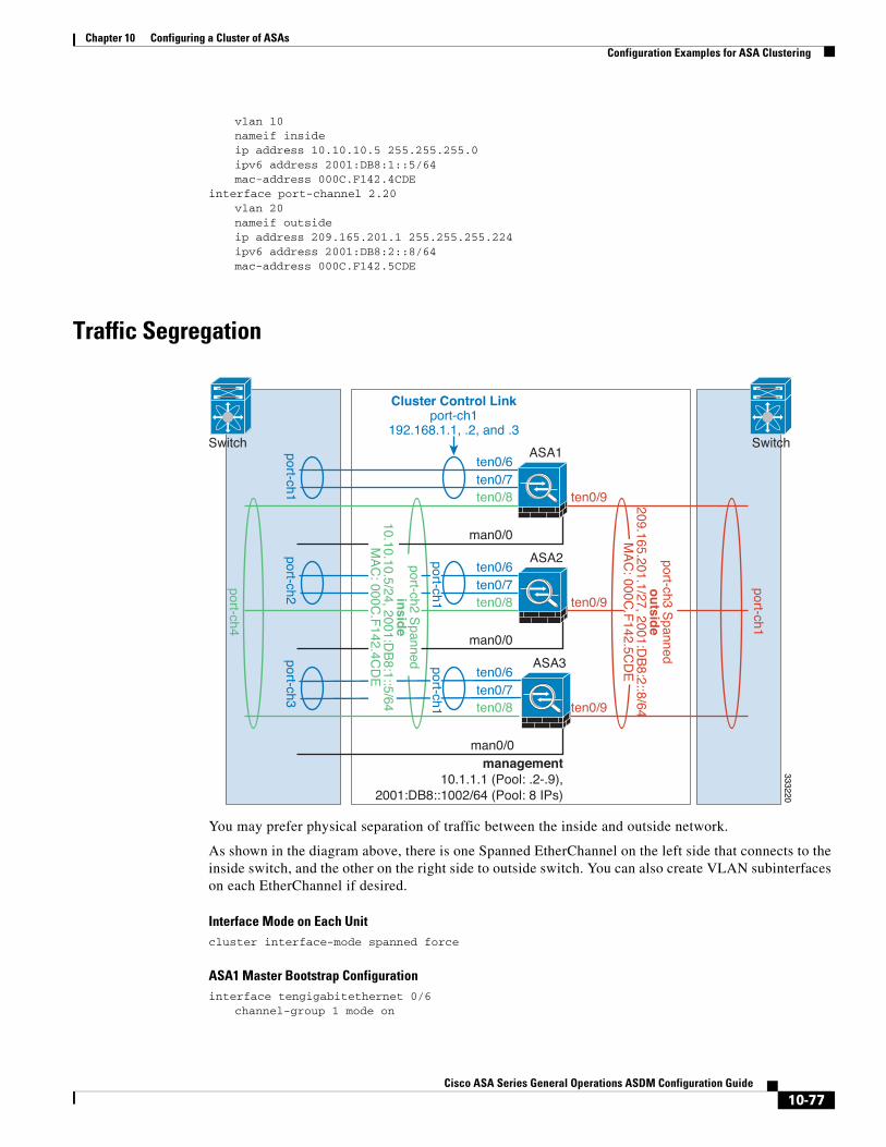
Chapter 10 Configuring a Cluster of ASAs Configuration Examples for ASA Clustering
vlan 10nameif insideip address 10.10.10.5 255.255.255.0ipv6 address 2001:DB8:1::5/64mac-address 000C.F142.4CDE
interface port-channel 2.20vlan 20nameif outsideip address 209.165.201.1 255.255.255.224ipv6 address 2001:DB8:2::8/64mac-address 000C.F142.5CDE
Traffic Segregation
You may prefer physical separation of traffic between the inside and outside network.
As shown in the diagram above, there is one Spanned EtherChannel on the left side that connects to the inside switch, and the other on the right side to outside switch. You can also create VLAN subinterfaces on each EtherChannel if desired.
Interface Mode on Each Unitcluster interface-mode spanned force
ASA1 Master Bootstrap Configurationinterface tengigabitethernet 0/6
channel-group 1 mode on
ASA1
333220
ten0/6ten0/7ten0/8
man0/0
ten0/9
ASA2ten0/6ten0/7ten0/8
man0/0
ten0/9
ASA3ten0/6ten0/7ten0/8 ten0/9
Switch port-ch1port-ch2
port-ch3
Cluster Control Linkport-ch1
192.168.1.1, .2, and .3
port-ch4
port-ch1
port-ch1port-ch1
port-ch2 Spanned
insid
e10.10.10.5/24, 2001:D
B8:1::5/64
MA
C: 000C
.F142.4C
DE
Switch
man0/0
port-ch3 Spanned
ou
tside
209.165.201.1/27, 2001:DB
8:2::8/64M
AC
: 000C.F
142.5CD
E
management10.1.1.1 (Pool: .2-.9),
2001:DB8::1002/64 (Pool: 8 IPs)
10-77Cisco ASA Series General Operations ASDM Configuration Guide

Chapter 10 Configuring a Cluster of ASAs Configuration Examples for ASA Clustering
no shutdowninterface tengigabitethernet 0/7
channel-group 1 mode onno shutdown
interface port-channel 1description CCL
cluster group cluster1local-unit asa1cluster-interface port-channel1 ip 192.168.1.1 255.255.255.0priority 1key chuntheunavoidableenable noconfirm
ASA2 Slave Bootstrap Configurationinterface tengigabitethernet 0/6
channel-group 1 mode onno shutdown
interface tengigabitethernet 0/7channel-group 1 mode onno shutdown
interface port-channel 1description CCL
cluster group cluster1local-unit asa2cluster-interface port-channel1 ip 192.168.1.2 255.255.255.0priority 2key chuntheunavoidableenable as-slave
ASA3 Slave Bootstrap Configurationinterface tengigabitethernet 0/6
channel-group 1 mode onno shutdown
interface tengigabitethernet 0/7channel-group 1 mode onno shutdown
interface port-channel 1description CCL
cluster group cluster1local-unit asa3cluster-interface port-channel1 ip 192.168.1.3 255.255.255.0priority 3key chuntheunavoidableenable as-slave
Master Interface Configurationip local pool mgmt 10.1.1.2-10.1.1.9ipv6 local pool mgmtipv6 2001:DB8::1002/64 8
interface management 0/0nameif managementip address 10.1.1.1 255.255.255.0 cluster-pool mgmtipv6 address 2001:DB8::1001/32 cluster-pool mgmtipv6security-level 100management-only
10-78Cisco ASA Series General Operations ASDM Configuration Guide
Chapter 10 Configuring a Cluster of ASAs Configuration Examples for ASA Clustering
no shutdown
interface tengigabitethernet 0/8channel-group 2 mode activeno shutdown
interface port-channel 2port-channel span-clusternameif insideip address 10.10.10.5 255.255.255.0ipv6 address 2001:DB8:1::5/64mac-address 000C.F142.4CDE
interface tengigabitethernet 0/9channel-group 3 mode activeno shutdown
interface port-channel 3port-channel span-clusternameif outsideip address 209.165.201.1 255.255.255.224ipv6 address 2001:DB8:2::8/64mac-address 000C.F142.5CDE
10-79Cisco ASA Series General Operations ASDM Configuration Guide
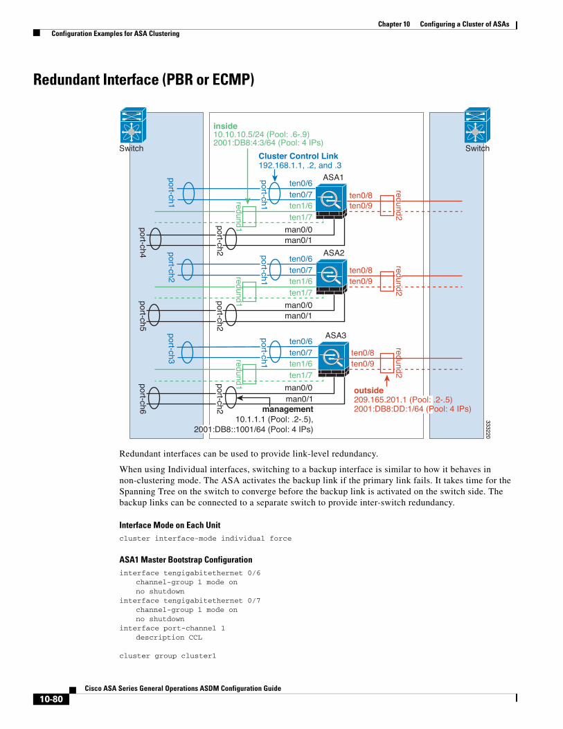
Chapter 10 Configuring a Cluster of ASAs Configuration Examples for ASA Clustering
Redundant Interface (PBR or ECMP)
Redundant interfaces can be used to provide link-level redundancy.
When using Individual interfaces, switching to a backup interface is similar to how it behaves in non-clustering mode. The ASA activates the backup link if the primary link fails. It takes time for the Spanning Tree on the switch to converge before the backup link is activated on the switch side. The backup links can be connected to a separate switch to provide inter-switch redundancy.
Interface Mode on Each Unitcluster interface-mode individual force
ASA1 Master Bootstrap Configurationinterface tengigabitethernet 0/6
channel-group 1 mode onno shutdown
interface tengigabitethernet 0/7channel-group 1 mode onno shutdown
interface port-channel 1description CCL
cluster group cluster1
ASA1
333220
ten0/6ten0/7ten1/6
man0/0
ten1/7ten0/9
man0/1
ASA2ten0/6ten0/7ten1/6 ten0/9
ASA3ten0/6ten0/7ten1/6
ten0/8
ten0/8
ten0/8ten0/9
Switch
port-ch1
port-ch4port-ch5
port-ch6
port-ch2port-ch3
Cluster Control Link192.168.1.1, .2, and .3
inside10.10.10.5/24 (Pool: .6-.9)2001:DB8:4:3/64 (Pool: 4 IPs)
port-ch1port-ch1
port-ch1
port-ch2
Switch
man0/1management
10.1.1.1 (Pool: .2-.5),2001:DB8::1001/64 (Pool: 4 IPs)
man0/0
ten1/7
man0/1
man0/0
ten1/7
port-ch2port-ch2
outside209.165.201.1 (Pool: .2-.5)2001:DB8:DD:1/64 (Pool: 4 IPs)
redund1redund1
redund1
redund2redund2
redund2
10-80Cisco ASA Series General Operations ASDM Configuration Guide
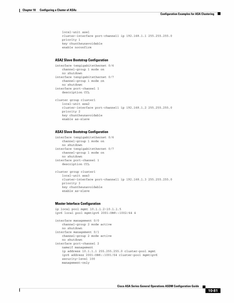
Chapter 10 Configuring a Cluster of ASAs Configuration Examples for ASA Clustering
local-unit asa1cluster-interface port-channel1 ip 192.168.1.1 255.255.255.0priority 1key chuntheunavoidableenable noconfirm
ASA2 Slave Bootstrap Configurationinterface tengigabitethernet 0/6
channel-group 1 mode onno shutdown
interface tengigabitethernet 0/7channel-group 1 mode onno shutdown
interface port-channel 1description CCL
cluster group cluster1local-unit asa2cluster-interface port-channel1 ip 192.168.1.2 255.255.255.0priority 2key chuntheunavoidableenable as-slave
ASA3 Slave Bootstrap Configurationinterface tengigabitethernet 0/6
channel-group 1 mode onno shutdown
interface tengigabitethernet 0/7channel-group 1 mode onno shutdown
interface port-channel 1description CCL
cluster group cluster1local-unit asa3cluster-interface port-channel1 ip 192.168.1.3 255.255.255.0priority 3key chuntheunavoidableenable as-slave
Master Interface Configurationip local pool mgmt 10.1.1.2-10.1.1.5ipv6 local pool mgmtipv6 2001:DB8::1002/64 4
interface management 0/0channel-group 2 mode activeno shutdown
interface management 0/1channel-group 2 mode activeno shutdown
interface port-channel 2nameif managementip address 10.1.1.1 255.255.255.0 cluster-pool mgmtipv6 address 2001:DB8::1001/64 cluster-pool mgmtipv6security-level 100management-only
10-81Cisco ASA Series General Operations ASDM Configuration Guide

Chapter 10 Configuring a Cluster of ASAs Configuration Examples for ASA Clustering
ip local pool inside 10.10.10.6-10.10.10.9ipv6 local pool insideipv6 2001:DB8:4:4/64 4
interface redundant 1member-interface tengigabitethernet 1/6member-interface tengigabitethernet 1/7
nameif insideip address 10.10.10.5 255.255.255.0 cluster-pool insideipv6 address 2001:DB8:4:3/64 cluster-pool insideipv6security-level 100
ip local pool outside 209.165.201.2-209.165.201.5ipv6 local pool outsideipv6 2001:DB8:DD:2/64 4
interface redundant 2member-interface tengigabitethernet 0/8member-interface tengigabitethernet 0/9
nameif outsideip address 209.165.201.1 255.255.255.224 cluster-pool outsideipv6 address 2001:DB8:DD:1/64 cluster-pool outsideipv6security-level 0
Spanned EtherChannel With Backup LinksThe maximum number of active ports in an etherchannel is limited to 8 from the switch side. If you have an 8-ASA cluster, and you allocate 2 ports per unit to the EtherChannel, for a total of 16 ports total, then 8 of them have to be in standby mode. The ASA uses LACP to negotiate which links should be active or standby. If you enable multi-switch EtherChannel using VSS or vPC, you can achieve inter-switch redundancy. On the ASA, all physical ports are ordered first by the slot number then by the port number. In the following figure, the lower ordered port is the “primary” port (for example, GigabitEthernet 0/0), and the other one is the “secondary” port (for example, GigabitEthernet 0/1). You must guarantee symmetry in the hardware connection: all primary links must terminate on one switch, and all secondary links must terminate on another switch if VSS/vPC is used. The following diagram shows what happens when the total number of links grows as more units join the cluster:
10-82Cisco ASA Series General Operations ASDM Configuration Guide

Chapter 10 Configuring a Cluster of ASAs Configuration Examples for ASA Clustering
The principle is to first maximize the number of active ports in the channel, and secondly keep the number of active primary ports and the number of active secondary ports in balance. Note that when a 5th unit joins the cluster, traffic is not balanced evenly between all units.
3332
18
Router orAccess Switch
Virtual Switch Link
ASA1
ASA8
1. Up to 4 units
Router orAccess Switch
Virtual Switch Link
ASA1
ASA2
ASA3
ASA4
2. 5th unit joined
3. Maximum of 8 units
Router orAccess Switch
Virtual Switch Link
ASA1
ASA2
ASA3
ASA4
ASA5
Switch 2Switch 1Switch 2Switch 1Switch 2Switch 1
10-83Cisco ASA Series General Operations ASDM Configuration Guide

Chapter 10 Configuring a Cluster of ASAs Configuration Examples for ASA Clustering
Link or device failure is handled with the same principle. You may end up with a less-than-perfect load balancing situation. The following figure shows a 4-unit cluster with a single link failure on one of the units.
3332
17
Router orAccess Switch
Virtual Switch Link
ASA1
ASA2
ASA3
ASA4
Switch 2Switch 1
10-84Cisco ASA Series General Operations ASDM Configuration Guide

Chapter 10 Configuring a Cluster of ASAs Configuration Examples for ASA Clustering
There could be multiple EtherChannels configured in the network. The following diagram shows an EtherChannel on the inside and one on the outside. An ASA is removed from the cluster if both primary and secondary links in one EtherChannel fail. This prevents the ASA from receiving traffic from the outside network when it has already lost connectivity to the inside network.
Interface Mode on Each Unitcluster interface-mode spanned force
ASA1 Master Bootstrap Configurationinterface tengigabitethernet 0/6
channel-group 1 mode onno shutdown
interface tengigabitethernet 0/7channel-group 1 mode onno shutdown
interface tengigabitethernet 0/8channel-group 1 mode onno shutdown
interface tengigabitethernet 0/9channel-group 1 mode onno shutdown
interface port-channel 1description CCL
Virtual Switch LinkSwitch 1 Switch 2
Switch 3 Switch 4
Router orAccess Switch
Router orAccess Switch
Virtual Switch Link
3332
16
ASA1 ASA2 ASA3 ASA4
Inside
Outside
10-85Cisco ASA Series General Operations ASDM Configuration Guide
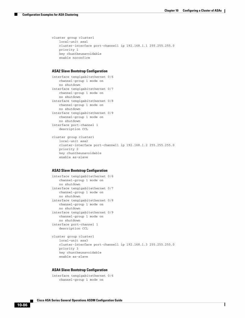
Chapter 10 Configuring a Cluster of ASAs Configuration Examples for ASA Clustering
cluster group cluster1local-unit asa1cluster-interface port-channel1 ip 192.168.1.1 255.255.255.0priority 1key chuntheunavoidableenable noconfirm
ASA2 Slave Bootstrap Configurationinterface tengigabitethernet 0/6
channel-group 1 mode onno shutdown
interface tengigabitethernet 0/7channel-group 1 mode onno shutdown
interface tengigabitethernet 0/8channel-group 1 mode onno shutdown
interface tengigabitethernet 0/9channel-group 1 mode onno shutdown
interface port-channel 1description CCL
cluster group cluster1local-unit asa2cluster-interface port-channel1 ip 192.168.1.2 255.255.255.0priority 2key chuntheunavoidableenable as-slave
ASA3 Slave Bootstrap Configurationinterface tengigabitethernet 0/6
channel-group 1 mode onno shutdown
interface tengigabitethernet 0/7channel-group 1 mode onno shutdown
interface tengigabitethernet 0/8channel-group 1 mode onno shutdown
interface tengigabitethernet 0/9channel-group 1 mode onno shutdown
interface port-channel 1description CCL
cluster group cluster1local-unit asa3cluster-interface port-channel1 ip 192.168.1.3 255.255.255.0priority 3key chuntheunavoidableenable as-slave
ASA4 Slave Bootstrap Configurationinterface tengigabitethernet 0/6
channel-group 1 mode on
10-86Cisco ASA Series General Operations ASDM Configuration Guide

Chapter 10 Configuring a Cluster of ASAs Configuration Examples for ASA Clustering
no shutdowninterface tengigabitethernet 0/7
channel-group 1 mode onno shutdown
interface tengigabitethernet 0/8channel-group 1 mode onno shutdown
interface tengigabitethernet 0/9channel-group 1 mode onno shutdown
interface port-channel 1description CCL
cluster group cluster1local-unit asa4cluster-interface port-channel1 ip 192.168.1.4 255.255.255.0priority 4key chuntheunavoidableenable as-slave
Master Interface Configurationip local pool mgmt 10.1.1.2-10.1.1.9
interface management 0/0channel-group 2 mode activeno shutdown
interface management 0/1channel-group 2 mode activeno shutdown
interface port-channel 2nameif managementip address 10.1.1.1 255.255.255.0 cluster-pool mgmtsecurity-level 100management-only
interface tengigabitethernet 1/6channel-group 3 mode active vss-id 1no shutdown
interface tengigabitethernet 1/7channel-group 3 mode active vss-id 2no shutdown
interface port-channel 3port-channel span-cluster vss-load-balancenameif insideip address 10.10.10.5 255.255.255.0mac-address 000C.F142.4CDE
interface tengigabitethernet 1/8channel-group 4 mode active vss-id 1no shutdown
interface tengigabitethernet 1/9channel-group 4 mode active vss-id 2no shutdown
interface port-channel 4port-channel span-cluster vss-load-balancenameif outsideip address 209.165.201.1 255.255.255.224mac-address 000C.F142.5CDE
10-87Cisco ASA Series General Operations ASDM Configuration Guide

Chapter 10 Configuring a Cluster of ASAs Feature History for ASA Clustering
Feature History for ASA ClusteringTable 10-3 lists each feature change and the platform release in which it was implemented. ASDM is backwards-compatible with multiple platform releases, so the specific ASDM release in which support was added is not listed.
Table 10-3 Feature History for Clustering
Feature NamePlatform Releases Feature Information
ASA Clustering for the ASA 5580 and 5585-X
9.0(1) ASA Clustering lets you group multiple ASAs together as a single logical device. A cluster provides all the convenience of a single device (management, integration into a network) while achieving the increased throughput and redundancy of multiple devices. ASA clustering is supported for the ASA 5580 and the ASA 5585-X; all units in a cluster must be the same model with the same hardware specifications. See the configuration guide for a list of unsupported features when clustering is enabled.
We introduced or modified the following screens:
Home > Device Dashboard Home > Cluster DashboardHome > Cluster Firewall DashboardConfiguration > Device Management > Advanced > Address Pools > MAC Address PoolsConfiguration > Device Management > High Availability and Scalability > ASA ClusterConfiguration > Device Management > Logging > Syslog Setup > AdvancedConfiguration > Device Setup > Interfaces > Add/Edit Interface > AdvancedConfiguration > Device Setup > Interfaces > Add/Edit Interface > IPv6Configuration > Device Setup > Interfaces > Add/Edit EtherChannel Interface > AdvancedConfiguration > Firewall > Advanced > Per-Session NAT RulesMonitoring > ASA ClusterMonitoring > Properties > System Resources Graphs > Cluster Control LinkTools > Preferences > GeneralTools > System ReloadTools > Upgrade Software from Local ComputerWizards > High Availability and Scalability WizardWizards > Packet Capture WizardWizards > Startup Wizard
ASA 5500-X support for clustering
9.1(4) The ASA 5512-X, ASA 5515-X, ASA 5525-X, ASA 5545-X, and ASA 5555-X now support 2-unit clusters. Clustering for 2 units is enabled by default in the base license; for the ASA 5512-X, you need the Security Plus license.
We did not modify any ASDM screens.
10-88Cisco ASA Series General Operations ASDM Configuration Guide

Chapter 10 Configuring a Cluster of ASAs Feature History for ASA Clustering
Improved VSS and vPC support for health check monitoring
9.1(4) If you configure the cluster control link as an EtherChannel (recommended), and it is connected to a VSS or vPC pair, you can now increase stability with health check monitoring. For some switches, such as the Nexus 5000, when one unit in the VSS/vPC is shutting down or booting up, EtherChannel member interfaces connected to that switch may appear to be Up to the ASA, but they are not passing traffic on the switch side. The ASA can be erroneously removed from the cluster if you set the ASA holdtime timeout to a low value (such as .8 seconds), and the ASA sends keepalive messages on one of these EtherChannel interfaces. When you enable the VSS/vPC health check feature, the ASA floods the keepalive messages on all EtherChannel interfaces in the cluster control link to ensure that at least one of the switches can receive them.
We modified the following screen: Configuration > Device Management > High Availability and Scalability > ASA Cluster
Support for cluster members at different geographical locations (inter-site); Individual Interface mode only
9.1(4) You can now place cluster members at different geographical locations when using individual interface mode.
We did not modify any ASDM screens.
Table 10-3 Feature History for Clustering (continued)
Feature NamePlatform Releases Feature Information
10-89Cisco ASA Series General Operations ASDM Configuration Guide

Chapter 10 Configuring a Cluster of ASAs Feature History for ASA Clustering
10-90Cisco ASA Series General Operations ASDM Configuration Guide


![Quick Configuration · [HUAWEI-vlanif5] ip address 10.10.1.1 24 [HUAWEI-vlanif5] quit 2 Add the management interface to the management VLAN. [HUAWEI] interface GigabitEthernet 0/0/8](https://img.pdfslide.net/doc/110x75/60d8c3ebe58a4d0f03534671/quick-configuration-huawei-vlanif5-ip-address-101011-24-huawei-vlanif5-quit.jpg)


![MonitorCommands - Cisco - Global Home Page · monitor session session_number destination {interfaces gigabitEthernet interface-id [network] |remote vlan vlan-id reflector-port gigabitEthernet](https://img.pdfslide.net/doc/110x75/5ffe52a35ccd7b2ad26460de/monitorcommands-cisco-global-home-page-monitor-session-sessionnumber-destination.jpg)