Embed Size (px)
Citation preview
JC; Reviewed: SPOC 6/25/2007
Solution & Interoperability Test Lab Application Notes ©2007 Avaya Inc. All Rights Reserved.
1 of 33 Ubigate-Juniper.doc
Avaya Solution & Interoperability Test Lab
Configuring a VPN Tunnel and QoS Between a Samsung UbigateTM iBG3026 Gateway and a Juniper Networks SSG 520 Gateway - Issue 1.0
Abstract
These Application Notes describe the procedures for configuring a site-to-site Virtual Private Network (VPN) tunnel between a Samsung UbigateTM iBG3026 Gateway and a Juniper Networks SSG 520 gateway with Quality of Service (QoS) to support an Avaya IP telephony infrastructure. The Samsung iBG3026 functions as a multi-service IP switch/router. A VPN/Internet Protocol Security (IPSec) option card provides encryption and decryption of IPSec VPN tunnels for the router. With a variety of QoS features and an Ethernet module with Power-over-Ethernet ports, the Samsung iBG3026 provides the necessary infrastructure for IP telephony.
JC; Reviewed: SPOC 6/25/2007
Solution & Interoperability Test Lab Application Notes ©2007 Avaya Inc. All Rights Reserved.
2 of 33 Ubigate-Juniper.doc
1. Introduction These Application Notes describe the procedures for configuring a Virtual Private Network (VPN) tunnel between a Samsung UbigateTM iBG3026 gateway and a Juniper Networks SSG 520 gateway with Quality of Service (QoS) to support an Avaya IP telephony infrastructure. The Samsung iBG3026 and Juniper SSG 520 have site-to-site IPSec VPN and QoS capabilities suitable for multi-site Avaya IP telephony deployment.
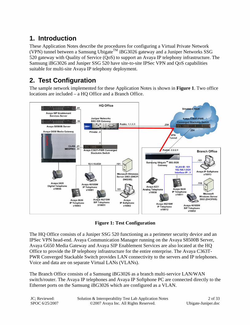
2. Test Configuration The sample network implemented for these Application Notes is shown in Figure 1. Two office locations are included – a HQ Office and a Branch Office.
Figure 1: Test Configuration The HQ Office consists of a Juniper SSG 520 functioning as a perimeter security device and an IPSec VPN head-end. Avaya Communication Manager running on the Avaya S8500B Server, Avaya G650 Media Gateway and Avaya SIP Enablement Services are also located at the HQ Office to provide the IP telephony infrastructure for the entire enterprise. The Avaya C363T-PWR Converged Stackable Switch provides LAN connectivity to the servers and IP telephones. Voice and data are on separate Virtual LANs (VLANs). The Branch Office consists of a Samsung iBG3026 as a branch multi-service LAN/WAN switch/router. The Avaya IP telephones and Avaya IP Softphone PC are connected directly to the Ethernet ports on the Samsung iBG3026 which are configured as a VLAN.
JC; Reviewed: SPOC 6/25/2007
Solution & Interoperability Test Lab Application Notes ©2007 Avaya Inc. All Rights Reserved.
3 of 33 Ubigate-Juniper.doc
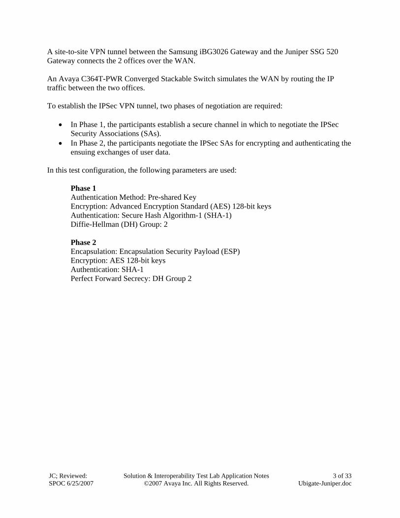
A site-to-site VPN tunnel between the Samsung iBG3026 Gateway and the Juniper SSG 520 Gateway connects the 2 offices over the WAN. An Avaya C364T-PWR Converged Stackable Switch simulates the WAN by routing the IP traffic between the two offices. To establish the IPSec VPN tunnel, two phases of negotiation are required:
• In Phase 1, the participants establish a secure channel in which to negotiate the IPSec Security Associations (SAs).
• In Phase 2, the participants negotiate the IPSec SAs for encrypting and authenticating the ensuing exchanges of user data.
In this test configuration, the following parameters are used:
Phase 1 Authentication Method: Pre-shared Key Encryption: Advanced Encryption Standard (AES) 128-bit keys Authentication: Secure Hash Algorithm-1 (SHA-1) Diffie-Hellman (DH) Group: 2 Phase 2 Encapsulation: Encapsulation Security Payload (ESP) Encryption: AES 128-bit keys Authentication: SHA-1 Perfect Forward Secrecy: DH Group 2
JC; Reviewed: SPOC 6/25/2007
Solution & Interoperability Test Lab Application Notes ©2007 Avaya Inc. All Rights Reserved.
4 of 33 Ubigate-Juniper.doc
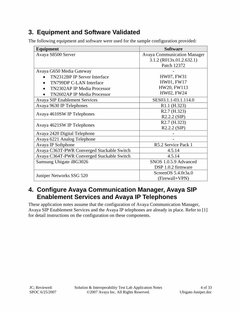
3. Equipment and Software Validated The following equipment and software were used for the sample configuration provided:
Equipment Software Avaya S8500 Server Avaya Communication Manager
3.1.2 (R013x.01.2.632.1) Patch 12372
Avaya G650 Media Gateway • TN2312BP IP Server Interface • TN799DP C-LAN Interface • TN2302AP IP Media Processor • TN2602AP IP Media Processor
- HW07, FW31 HW01, FW17 HW20, FW113 HW02, FW24
Avaya SIP Enablement Services SES03.1.1-03.1.114.0 Avaya 9630 IP Telephones R1.1 (H.323)
Avaya 4610SW IP Telephones R2.7 (H.323) R2.2.2 (SIP)
Avaya 4621SW IP Telephones R2.7 (H.323) R2.2.2 (SIP)
Avaya 2420 Digital Telephone - Avaya 6221 Analog Telephone - Avaya IP Softphone R5.2 Service Pack 1 Avaya C363T-PWR Converged Stackable Switch 4.5.14 Avaya C364T-PWR Converged Stackable Switch 4.5.14 Samsung Ubigate iBG3026 SNOS 1.0.5.9 Advanced
DSP 1.0.2 firmware
Juniper Networks SSG 520 ScreenOS 5.4.0r3a.0 (Firewall+VPN)
4. Configure Avaya Communication Manager, Avaya SIP Enablement Services and Avaya IP Telephones
These application notes assume that the configuration of Avaya Communication Manager, Avaya SIP Enablement Services and the Avaya IP telephones are already in place. Refer to [1] for detail instructions on the configuration on these components.
JC; Reviewed: SPOC 6/25/2007
Solution & Interoperability Test Lab Application Notes ©2007 Avaya Inc. All Rights Reserved.
5 of 33 Ubigate-Juniper.doc
5. Configure Juniper Networks SSG 520 The configuration steps utilize the web user interface (WebUI) of the Juniper SSG 520.
5.1. Access JUNIPER SSG 520 Step Description
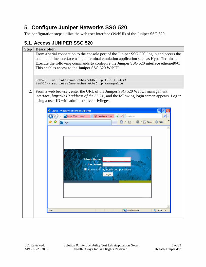
From a serial connection to the console port of the Juniper SSG 520, log in and access the command line interface using a terminal emulation application such as HyperTerminal. Execute the following commands to configure the Juniper SSG 520 interface ethernet0/0. This enables access to the Juniper SSG 520 WebUI.
1.
SSG520-> set interface ethernet0/0 ip 10.1.10.4/24 SSG520-> set interface ethernet0/0 ip manageable
2. From a web browser, enter the URL of the Juniper SSG 520 WebUI management interface, https://<IP address of the SSG>, and the following login screen appears. Log in using a user ID with administrative privileges.
JC; Reviewed: SPOC 6/25/2007
Solution & Interoperability Test Lab Application Notes ©2007 Avaya Inc. All Rights Reserved.
6 of 33 Ubigate-Juniper.doc
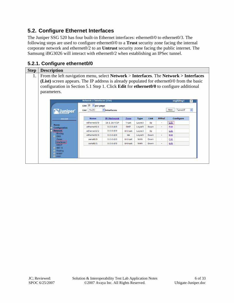
5.2. Configure Ethernet Interfaces The Juniper SSG 520 has four built-in Ethernet interfaces: ethernet0/0 to ethernet0/3. The following steps are used to configure ethernet0/0 to a Trust security zone facing the internal corporate network and ethernet0/2 to an Untrust security zone facing the public internet. The Samsung iBG3026 will interact with ethernet0/2 when establishing an IPSec tunnel.
5.2.1. Configure ethernet0/0 Step Description
1. From the left navigation menu, select Network > Interfaces. The Network > Interfaces (List) screen appears. The IP address is already populated for ethernet0/0 from the basic configuration in Section 5.1 Step 1. Click Edit for ethernet0/0 to configure additional parameters.
JC; Reviewed: SPOC 6/25/2007
Solution & Interoperability Test Lab Application Notes ©2007 Avaya Inc. All Rights Reserved.
7 of 33 Ubigate-Juniper.doc
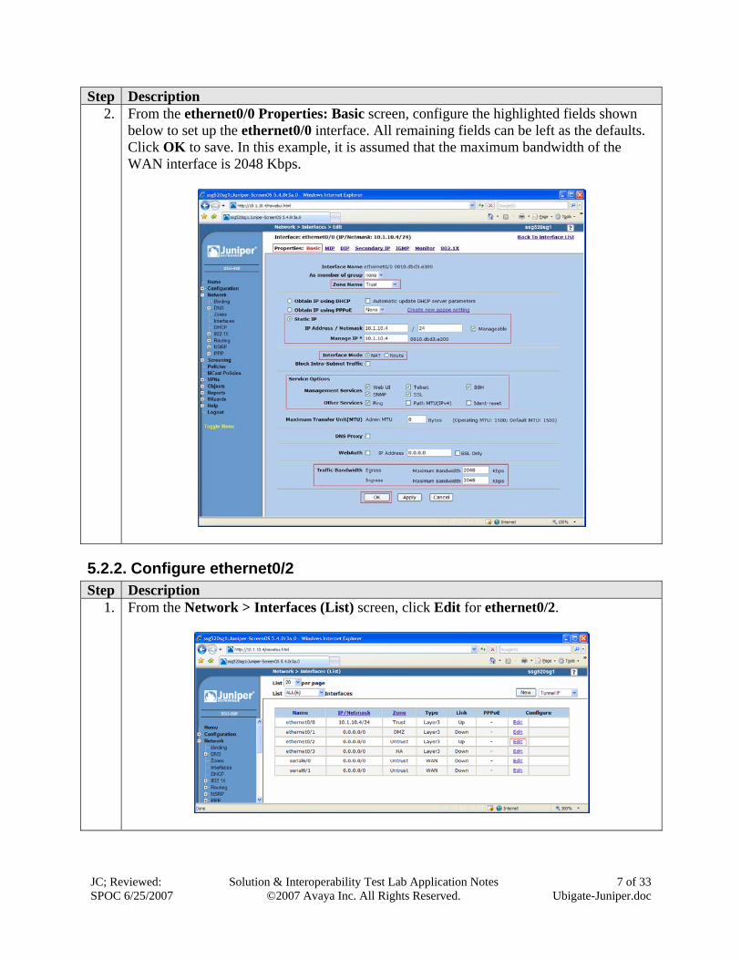
Step Description 2. From the ethernet0/0 Properties: Basic screen, configure the highlighted fields shown
below to set up the ethernet0/0 interface. All remaining fields can be left as the defaults. Click OK to save. In this example, it is assumed that the maximum bandwidth of the WAN interface is 2048 Kbps.
5.2.2. Configure ethernet0/2 Step Description
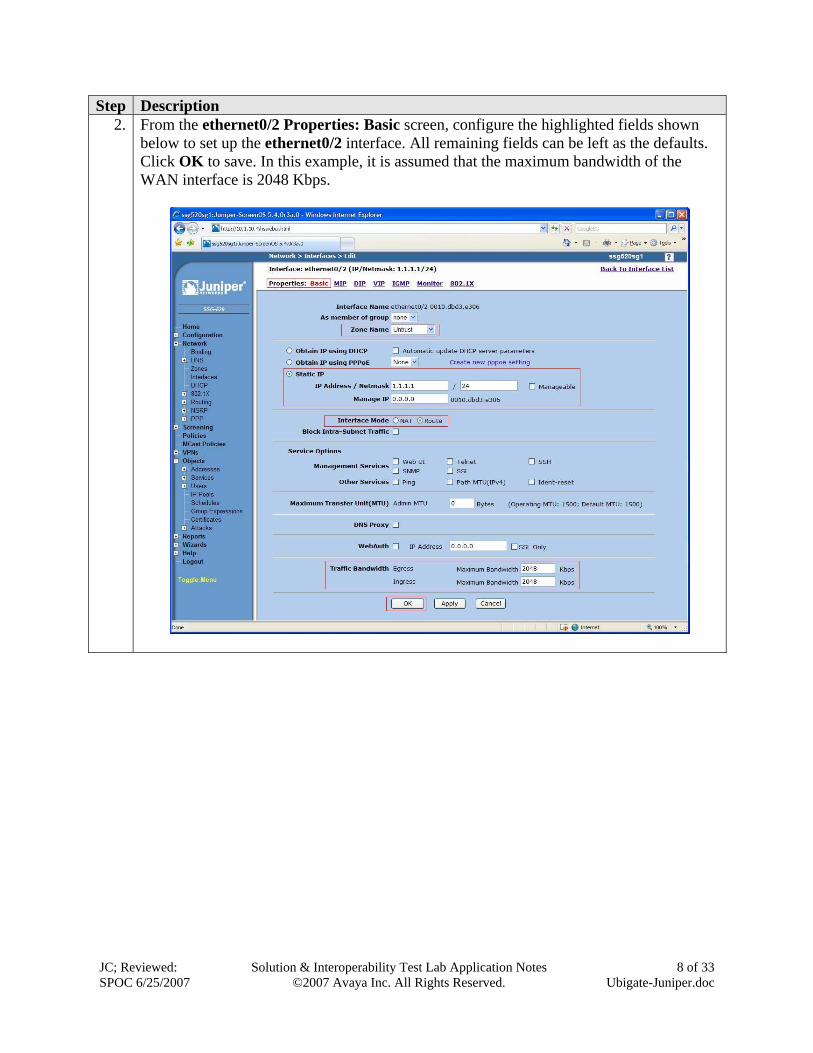
1. From the Network > Interfaces (List) screen, click Edit for ethernet0/2.
JC; Reviewed: SPOC 6/25/2007
Solution & Interoperability Test Lab Application Notes ©2007 Avaya Inc. All Rights Reserved.
8 of 33 Ubigate-Juniper.doc
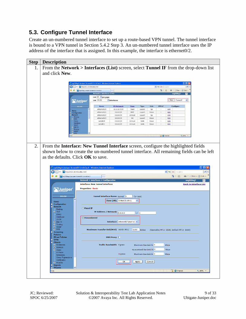
Step Description 2. From the ethernet0/2 Properties: Basic screen, configure the highlighted fields shown
below to set up the ethernet0/2 interface. All remaining fields can be left as the defaults. Click OK to save. In this example, it is assumed that the maximum bandwidth of the WAN interface is 2048 Kbps.
JC; Reviewed: SPOC 6/25/2007
Solution & Interoperability Test Lab Application Notes ©2007 Avaya Inc. All Rights Reserved.
9 of 33 Ubigate-Juniper.doc
5.3. Configure Tunnel Interface Create an un-numbered tunnel interface to set up a route-based VPN tunnel. The tunnel interface is bound to a VPN tunnel in Section 5.4.2 Step 3. An un-numbered tunnel interface uses the IP address of the interface that is assigned. In this example, the interface is ethernet0/2. Step Description
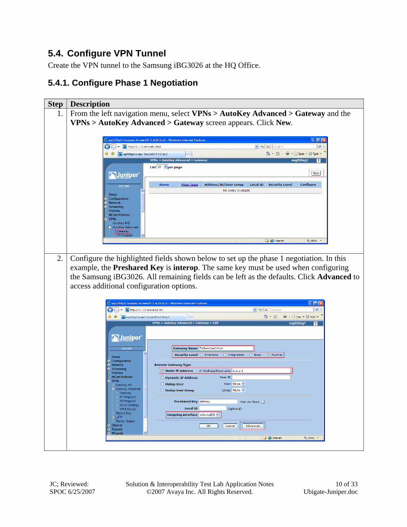
1. From the Network > Interfaces (List) screen, select Tunnel IF from the drop-down list and click New.
2. From the Interface: New Tunnel Interface screen, configure the highlighted fields shown below to create the un-numbered tunnel interface. All remaining fields can be left as the defaults. Click OK to save.
JC; Reviewed: SPOC 6/25/2007
Solution & Interoperability Test Lab Application Notes ©2007 Avaya Inc. All Rights Reserved.
10 of 33 Ubigate-Juniper.doc
5.4. Configure VPN Tunnel Create the VPN tunnel to the Samsung iBG3026 at the HQ Office.
5.4.1. Configure Phase 1 Negotiation Step Description
1. From the left navigation menu, select VPNs > AutoKey Advanced > Gateway and the VPNs > AutoKey Advanced > Gateway screen appears. Click New.
2. Configure the highlighted fields shown below to set up the phase 1 negotiation. In this example, the Preshared Key is interop. The same key must be used when configuring the Samsung iBG3026. All remaining fields can be left as the defaults. Click Advanced to access additional configuration options.
JC; Reviewed: SPOC 6/25/2007
Solution & Interoperability Test Lab Application Notes ©2007 Avaya Inc. All Rights Reserved.
11 of 33 Ubigate-Juniper.doc
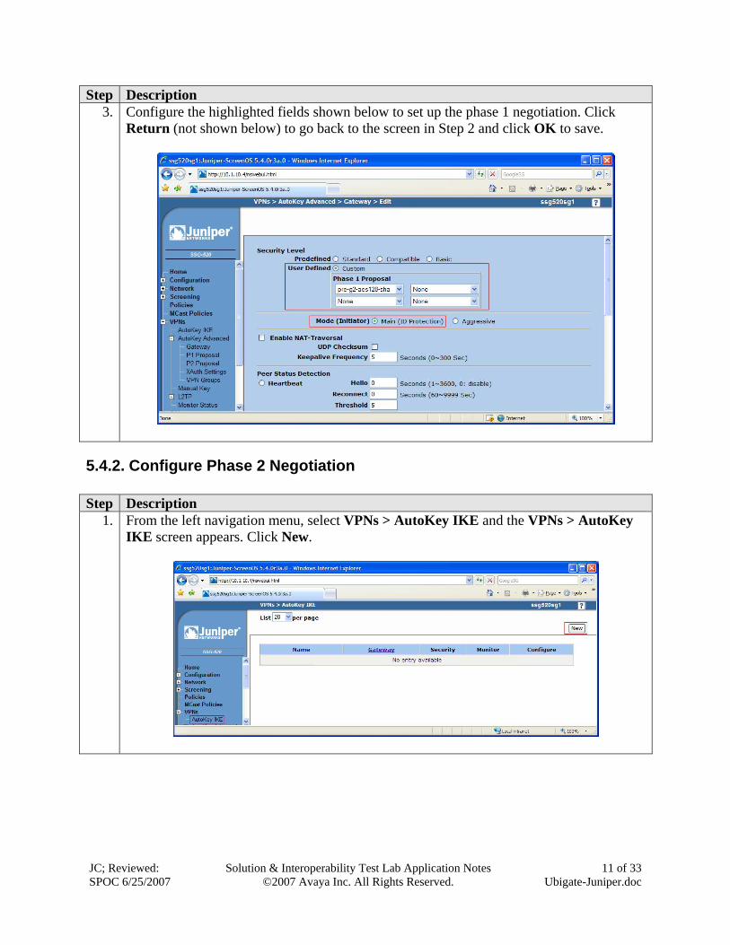
Step Description 3. Configure the highlighted fields shown below to set up the phase 1 negotiation. Click
Return (not shown below) to go back to the screen in Step 2 and click OK to save.
5.4.2. Configure Phase 2 Negotiation Step Description
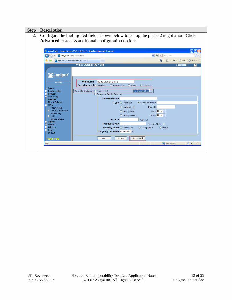
1. From the left navigation menu, select VPNs > AutoKey IKE and the VPNs > AutoKey IKE screen appears. Click New.
JC; Reviewed: SPOC 6/25/2007
Solution & Interoperability Test Lab Application Notes ©2007 Avaya Inc. All Rights Reserved.
12 of 33 Ubigate-Juniper.doc
Step Description 2. Configure the highlighted fields shown below to set up the phase 2 negotiation. Click
Advanced to access additional configuration options.
JC; Reviewed: SPOC 6/25/2007
Solution & Interoperability Test Lab Application Notes ©2007 Avaya Inc. All Rights Reserved.
13 of 33 Ubigate-Juniper.doc
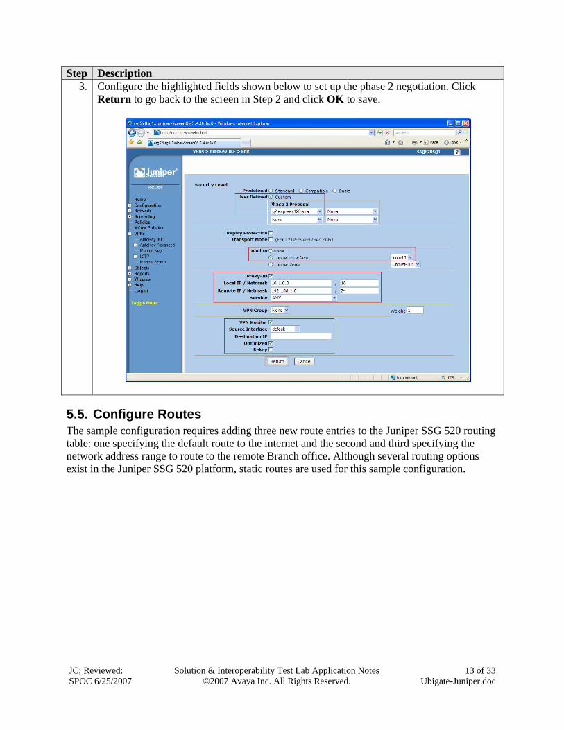
Step Description 3. Configure the highlighted fields shown below to set up the phase 2 negotiation. Click
Return to go back to the screen in Step 2 and click OK to save.
5.5. Configure Routes The sample configuration requires adding three new route entries to the Juniper SSG 520 routing table: one specifying the default route to the internet and the second and third specifying the network address range to route to the remote Branch office. Although several routing options exist in the Juniper SSG 520 platform, static routes are used for this sample configuration.
JC; Reviewed: SPOC 6/25/2007
Solution & Interoperability Test Lab Application Notes ©2007 Avaya Inc. All Rights Reserved.
14 of 33 Ubigate-Juniper.doc
5.5.1. Configure Default Route Step Description
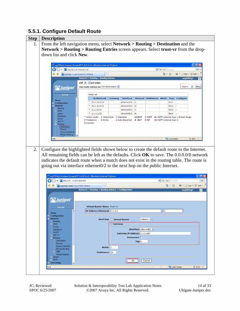
1. From the left navigation menu, select Network > Routing > Destination and the Network > Routing > Routing Entries screen appears. Select trust-vr from the drop-down list and click New.
2. Configure the highlighted fields shown below to create the default route to the Internet. All remaining fields can be left as the defaults. Click OK to save. The 0.0.0.0/0 network indicates the default route when a match does not exist in the routing table. The route is going out via interface ethernet0/2 to the next hop on the public Internet.
JC; Reviewed: SPOC 6/25/2007
Solution & Interoperability Test Lab Application Notes ©2007 Avaya Inc. All Rights Reserved.
15 of 33 Ubigate-Juniper.doc
5.5.2. Configure Route to Branch Office Step Description
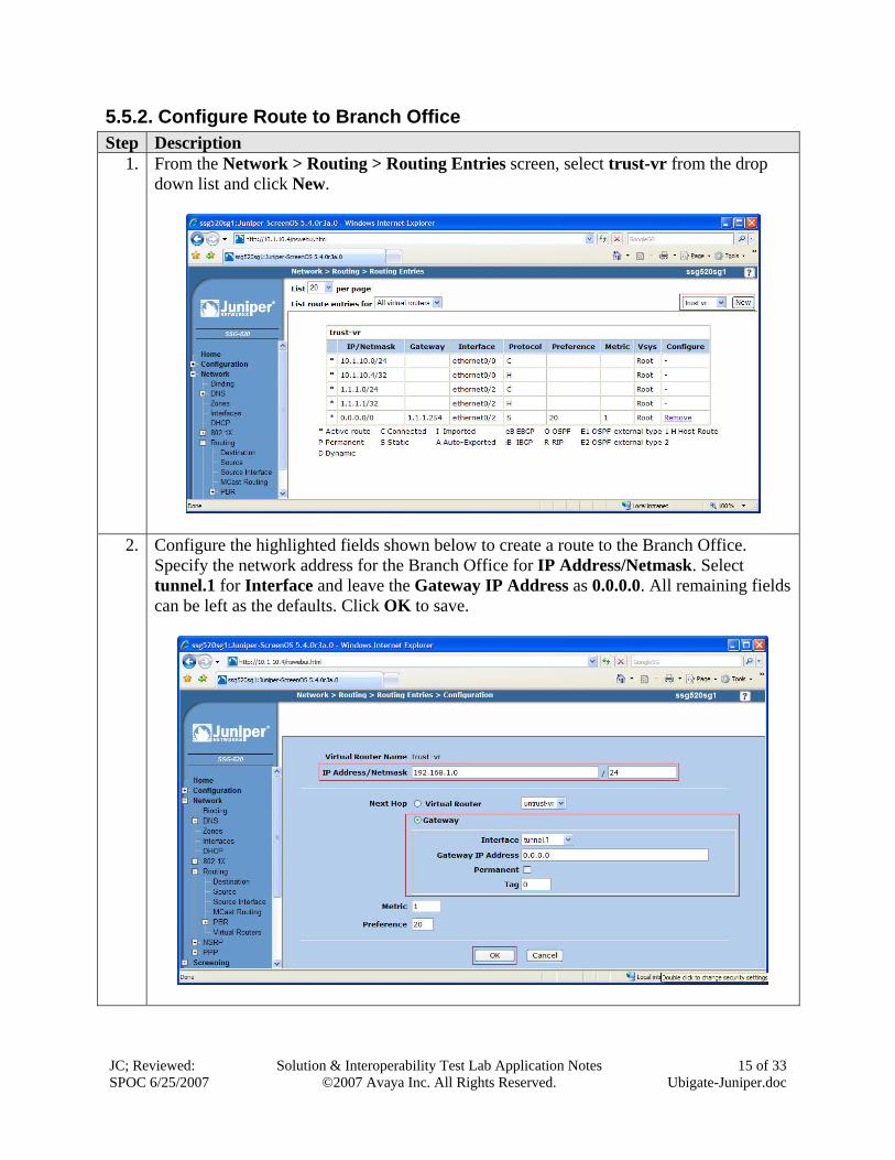
1. From the Network > Routing > Routing Entries screen, select trust-vr from the drop down list and click New.
2. Configure the highlighted fields shown below to create a route to the Branch Office. Specify the network address for the Branch Office for IP Address/Netmask. Select tunnel.1 for Interface and leave the Gateway IP Address as 0.0.0.0. All remaining fields can be left as the defaults. Click OK to save.
JC; Reviewed: SPOC 6/25/2007
Solution & Interoperability Test Lab Application Notes ©2007 Avaya Inc. All Rights Reserved.
16 of 33 Ubigate-Juniper.doc
Step Description 3. Repeat Step 1 to configure a new route.
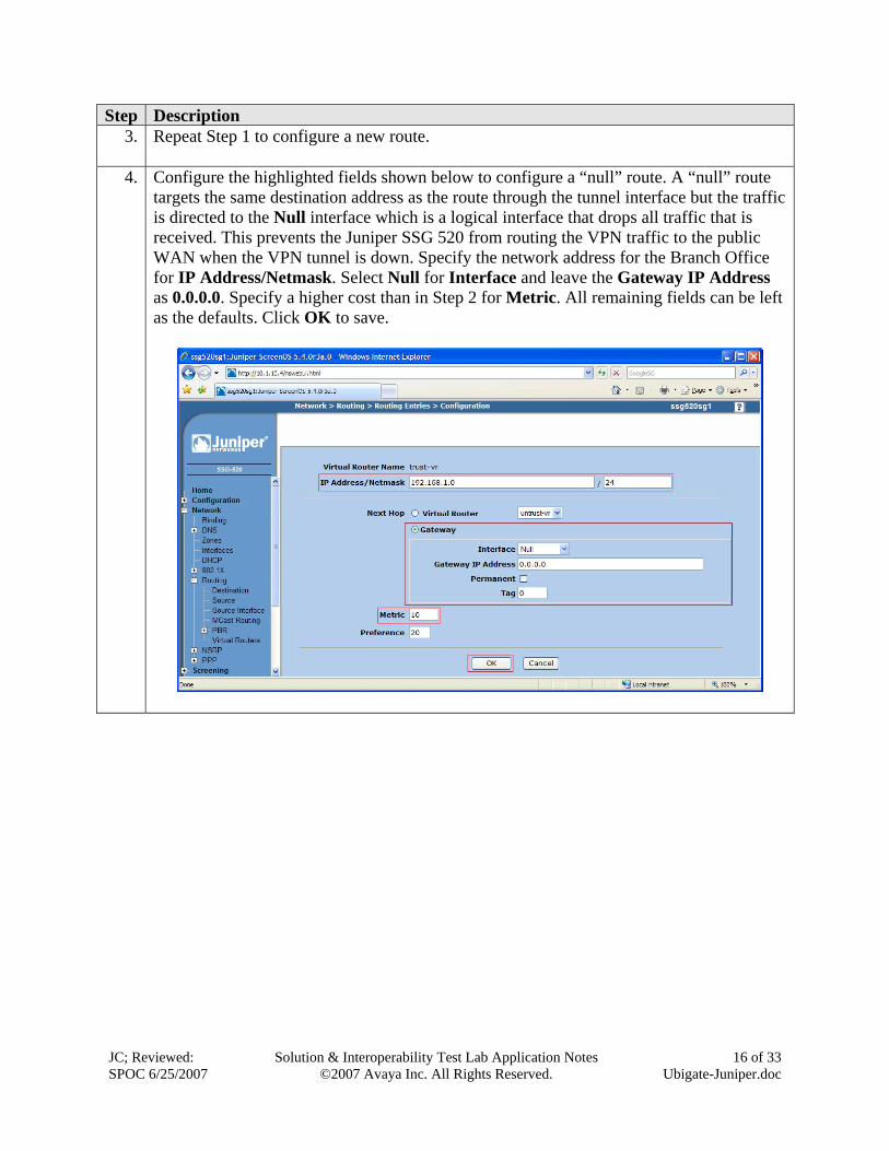
4. Configure the highlighted fields shown below to configure a “null” route. A “null” route
targets the same destination address as the route through the tunnel interface but the traffic is directed to the Null interface which is a logical interface that drops all traffic that is received. This prevents the Juniper SSG 520 from routing the VPN traffic to the public WAN when the VPN tunnel is down. Specify the network address for the Branch Office for IP Address/Netmask. Select Null for Interface and leave the Gateway IP Address as 0.0.0.0. Specify a higher cost than in Step 2 for Metric. All remaining fields can be left as the defaults. Click OK to save.
JC; Reviewed: SPOC 6/25/2007
Solution & Interoperability Test Lab Application Notes ©2007 Avaya Inc. All Rights Reserved.
17 of 33 Ubigate-Juniper.doc
5.6. Configure Addresses Create the IP addresses for the local and remote LAN to be used in the configuration of the policies. Step Description
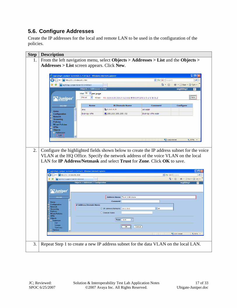
1. From the left navigation menu, select Objects > Addresses > List and the Objects > Addresses > List screen appears. Click New.
2. Configure the highlighted fields shown below to create the IP address subnet for the voice VLAN at the HQ Office. Specify the network address of the voice VLAN on the local LAN for IP Address/Netmask and select Trust for Zone. Click OK to save.
3. Repeat Step 1 to create a new IP address subnet for the data VLAN on the local LAN.
JC; Reviewed: SPOC 6/25/2007
Solution & Interoperability Test Lab Application Notes ©2007 Avaya Inc. All Rights Reserved.
18 of 33 Ubigate-Juniper.doc
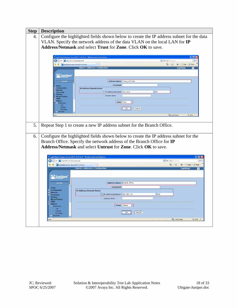
Step Description 4. Configure the highlighted fields shown below to create the IP address subnet for the data
VLAN. Specify the network address of the data VLAN on the local LAN for IP Address/Netmask and select Trust for Zone. Click OK to save.
5. Repeat Step 1 to create a new IP address subnet for the Branch Office.
6. Configure the highlighted fields shown below to create the IP address subnet for the Branch Office. Specify the network address of the Branch Office for IP Address/Netmask and select Untrust for Zone. Click OK to save.
JC; Reviewed: SPOC 6/25/2007
Solution & Interoperability Test Lab Application Notes ©2007 Avaya Inc. All Rights Reserved.
19 of 33 Ubigate-Juniper.doc
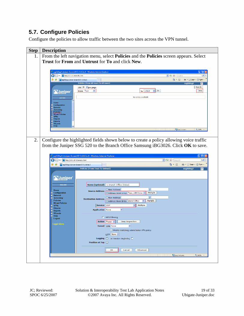
5.7. Configure Policies Configure the policies to allow traffic between the two sites across the VPN tunnel. Step Description
1. From the left navigation menu, select Policies and the Policies screen appears. Select Trust for From and Untrust for To and click New.
2. Configure the highlighted fields shown below to create a policy allowing voice traffic from the Juniper SSG 520 to the Branch Office Samsung iBG3026. Click OK to save.
JC; Reviewed: SPOC 6/25/2007
Solution & Interoperability Test Lab Application Notes ©2007 Avaya Inc. All Rights Reserved.
20 of 33 Ubigate-Juniper.doc
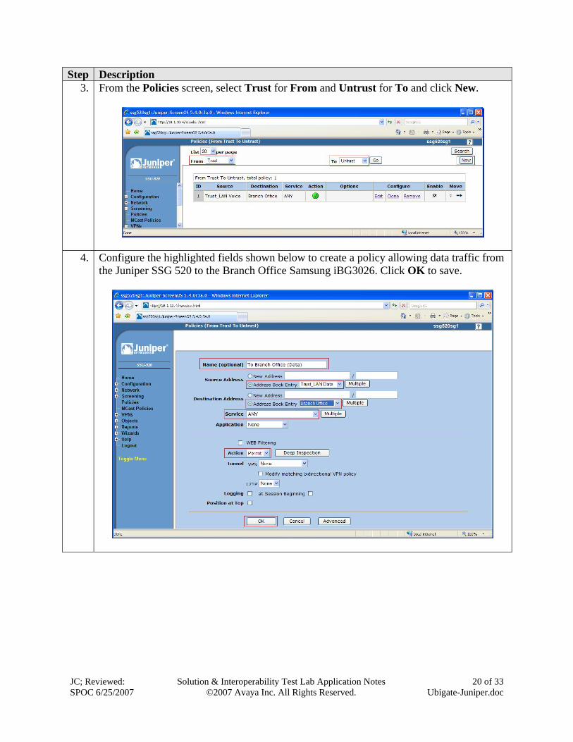
Step Description 3. From the Policies screen, select Trust for From and Untrust for To and click New.
4. Configure the highlighted fields shown below to create a policy allowing data traffic from the Juniper SSG 520 to the Branch Office Samsung iBG3026. Click OK to save.
JC; Reviewed: SPOC 6/25/2007
Solution & Interoperability Test Lab Application Notes ©2007 Avaya Inc. All Rights Reserved.
21 of 33 Ubigate-Juniper.doc
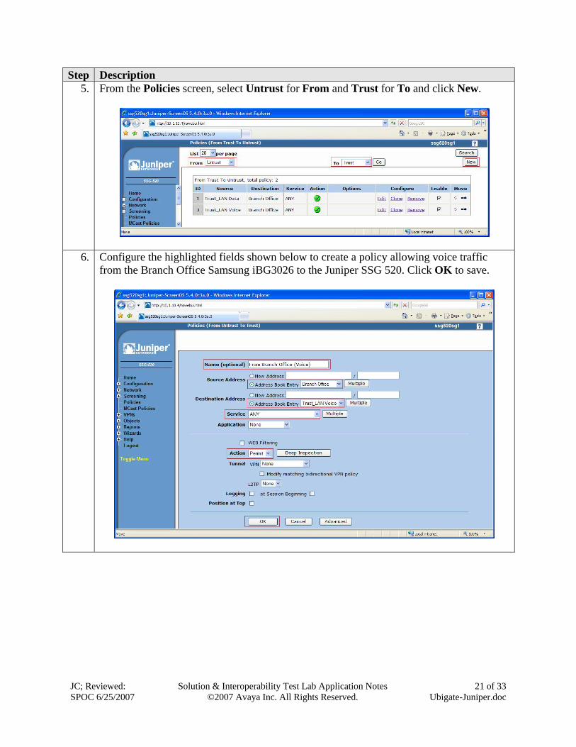
Step Description 5. From the Policies screen, select Untrust for From and Trust for To and click New.
6. Configure the highlighted fields shown below to create a policy allowing voice traffic from the Branch Office Samsung iBG3026 to the Juniper SSG 520. Click OK to save.
JC; Reviewed: SPOC 6/25/2007
Solution & Interoperability Test Lab Application Notes ©2007 Avaya Inc. All Rights Reserved.
22 of 33 Ubigate-Juniper.doc
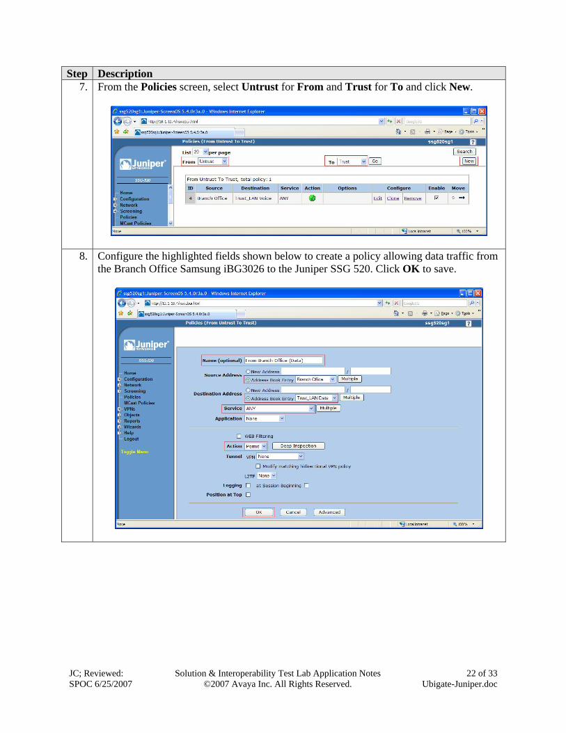
Step Description 7. From the Policies screen, select Untrust for From and Trust for To and click New.
8. Configure the highlighted fields shown below to create a policy allowing data traffic from the Branch Office Samsung iBG3026 to the Juniper SSG 520. Click OK to save.
JC; Reviewed: SPOC 6/25/2007
Solution & Interoperability Test Lab Application Notes ©2007 Avaya Inc. All Rights Reserved.
23 of 33 Ubigate-Juniper.doc
5.8. Configure Quality of Service Juniper Networks recommends the following ways to manage bandwidth for VoIP services using the standard traffic shaping mechanisms.
• Guarantee bandwidth for VoIP traffic – The most effective way to guarantee the bandwidth for VoIP service and still allow other types of traffic on the interface is to create a policy which guarantees the minimum bandwidth necessary for the amount of VoIP traffic that is expected on the interface, and to set the priority queuing to the highest level. The advantage of this strategy is that VoIP can use additional bandwidth when available, and other types of traffic can use the bandwidth that is not guaranteed for VoIP when the bandwidth is not being used.
• Limit bandwidth for non-VoIP traffic – By setting a maximum bandwidth for non-VoIP traffic, the remaining bandwidth is available to VoIP traffic. The level of priority queuing for VoIP traffic is also set to the highest level. The disadvantage of this method is that non-VoIP traffic cannot use additional bandwidth, even when the bandwidth is not being used by VoIP traffic.
• Use priority queuing and Differentiated Services Codepoint (DSCP) marking – Guaranteeing bandwidth for VoIP traffic and limiting bandwidth for non-VoIP traffic both govern throughput on the Juniper SSG 520. DSCP marking enables the priority queuing settings downstream to be preserved. At the same time, received DSCP value set by the originating networking device or upstream router can be kept or changed so that the next hop router, typically the LAN or WAN edge router, can enforce QoS in its DiffServ domain. By default, for VPN configurations, the Juniper SSG 520 copies the DSCP marking from the inner header of the IP packet to the outer header, so that the next hop router can enforce the correct QoS on the encrypted traffic.
In this configuration, QoS is achieved by guaranteeing the bandwidth for VoIP traffic and setting it to the highest priority. DSCP is already marked by the Avaya S8500B Server, CLAN circuit packs, MedPro circuit packs and Avaya IP telephones and DSCP will be preserved as it passes through the VPN tunnel.
JC; Reviewed: SPOC 6/25/2007
Solution & Interoperability Test Lab Application Notes ©2007 Avaya Inc. All Rights Reserved.
24 of 33 Ubigate-Juniper.doc
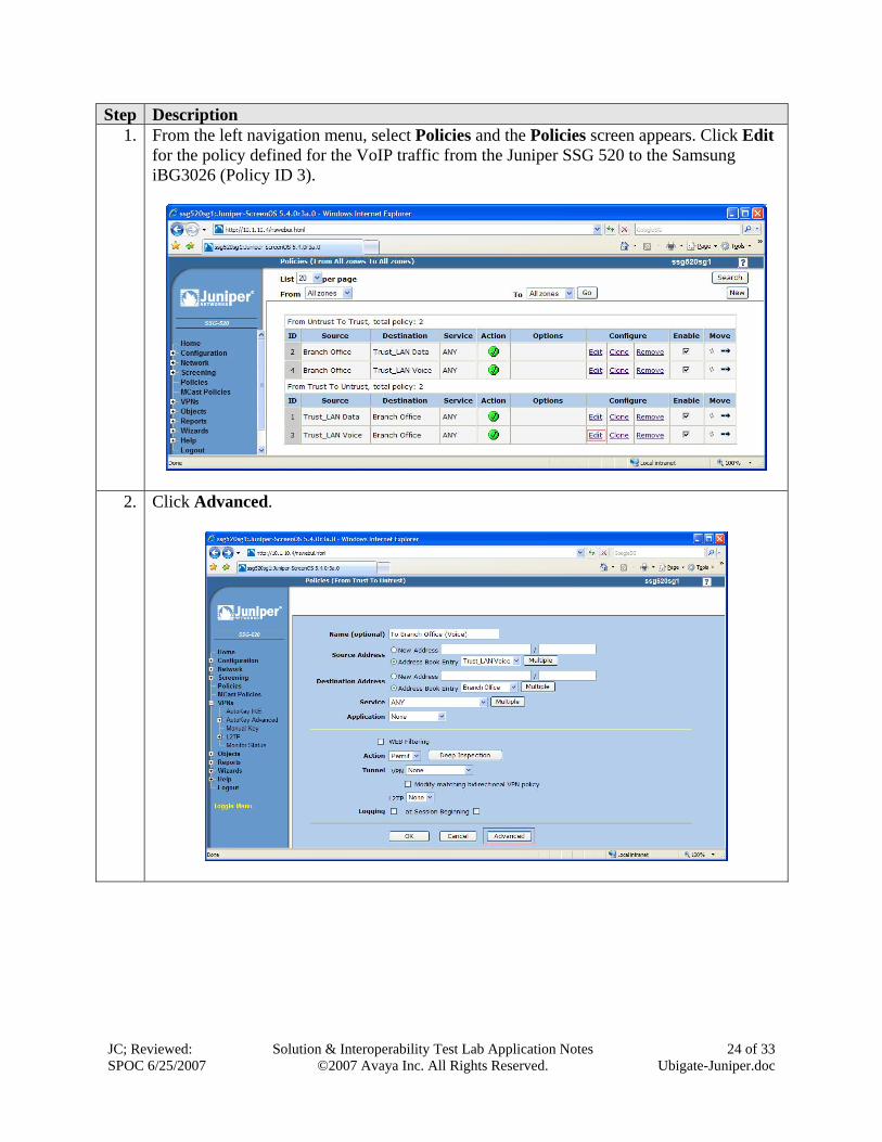
Step Description 1. From the left navigation menu, select Policies and the Policies screen appears. Click Edit
for the policy defined for the VoIP traffic from the Juniper SSG 520 to the Samsung iBG3026 (Policy ID 3).
2. Click Advanced.
JC; Reviewed: SPOC 6/25/2007
Solution & Interoperability Test Lab Application Notes ©2007 Avaya Inc. All Rights Reserved.
25 of 33 Ubigate-Juniper.doc
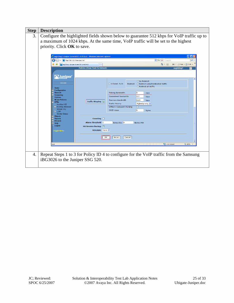
Step Description 3. Configure the highlighted fields shown below to guarantee 512 kbps for VoIP traffic up to
a maximum of 1024 kbps. At the same time, VoIP traffic will be set to the highest priority. Click OK to save.
4. Repeat Steps 1 to 3 for Policy ID 4 to configure for the VoIP traffic from the Samsung iBG3026 to the Juniper SSG 520.
JC; Reviewed: SPOC 6/25/2007
Solution & Interoperability Test Lab Application Notes ©2007 Avaya Inc. All Rights Reserved.
26 of 33 Ubigate-Juniper.doc
6. Configure Samsung Ubigate iBG3026 Gateway The Samsung iBG3026 provides both browser-based and command line-based (telnet or console port access) administrative interfaces. However, since the full range of necessary configuration features is supported only via the command line interface (CLI), the steps in this section use only the CLI.
6.1. Configure Ethernet and VLAN Interfaces Step Description
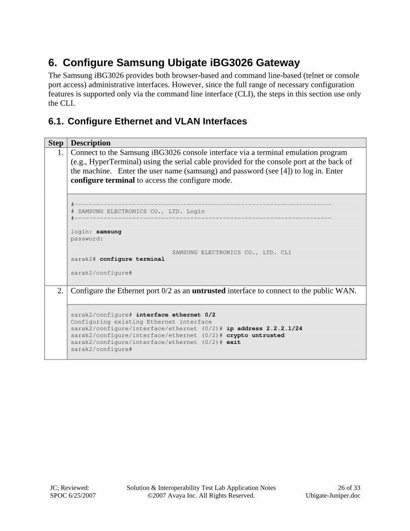
Connect to the Samsung iBG3026 console interface via a terminal emulation program (e.g., HyperTerminal) using the serial cable provided for the console port at the back of the machine. Enter the user name (samsung) and password (see [4]) to log in. Enter configure terminal to access the configure mode.
1.
#----------------------------------------------------------------------- # SAMSUNG ELECTRONICS CO., LTD. Login #----------------------------------------------------------------------- login: samsung password: SAMSUNG ELECTRONICS CO., LTD. CLI sarak2# configure terminal sarak2/configure#
Configure the Ethernet port 0/2 as an untrusted interface to connect to the public WAN.
2.
sarak2/configure# interface ethernet 0/2 Configuring existing Ethernet interface sarak2/configure/interface/ethernet (0/2)# ip address 2.2.2.1/24 sarak2/configure/interface/ethernet (0/2)# crypto untrusted sarak2/configure/interface/ethernet (0/2)# exit sarak2/configure#
JC; Reviewed: SPOC 6/25/2007
Solution & Interoperability Test Lab Application Notes ©2007 Avaya Inc. All Rights Reserved.
27 of 33 Ubigate-Juniper.doc
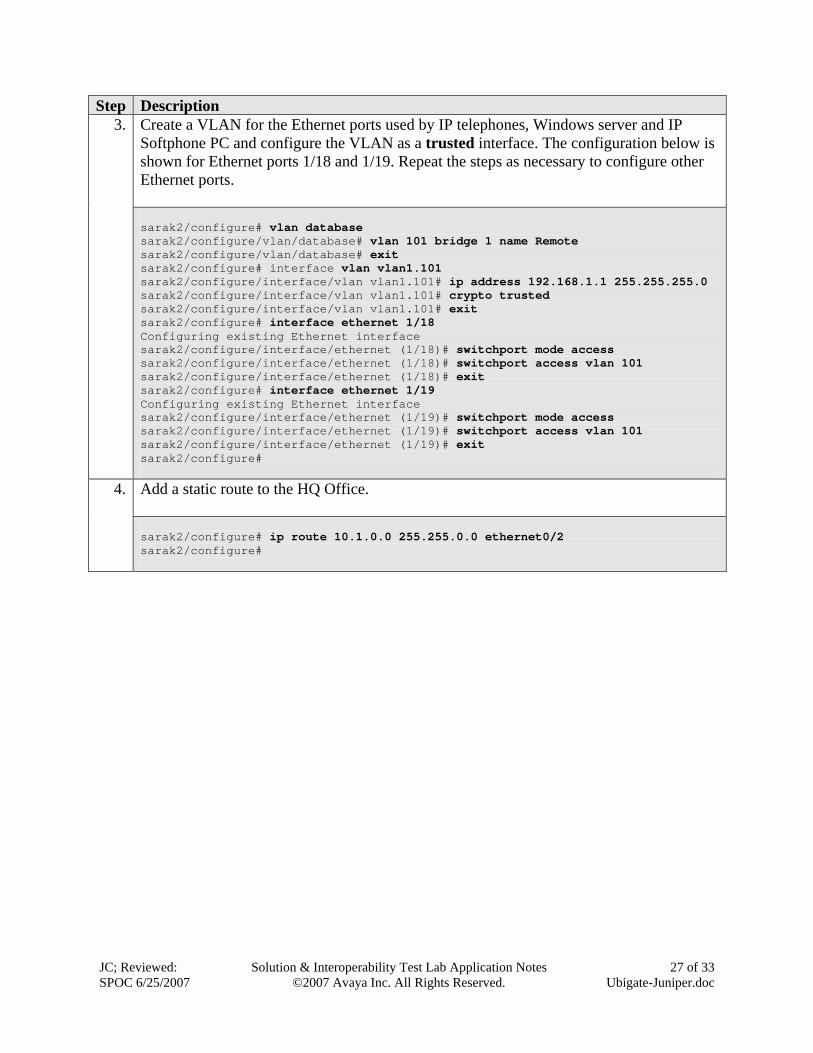
Step Description Create a VLAN for the Ethernet ports used by IP telephones, Windows server and IP Softphone PC and configure the VLAN as a trusted interface. The configuration below is shown for Ethernet ports 1/18 and 1/19. Repeat the steps as necessary to configure other Ethernet ports.
3.
sarak2/configure# vlan database sarak2/configure/vlan/database# vlan 101 bridge 1 name Remote sarak2/configure/vlan/database# exit sarak2/configure# interface vlan vlan1.101 sarak2/configure/interface/vlan vlan1.101# ip address 192.168.1.1 255.255.255.0 sarak2/configure/interface/vlan vlan1.101# crypto trusted sarak2/configure/interface/vlan vlan1.101# exit sarak2/configure# interface ethernet 1/18 Configuring existing Ethernet interface sarak2/configure/interface/ethernet (1/18)# switchport mode access sarak2/configure/interface/ethernet (1/18)# switchport access vlan 101 sarak2/configure/interface/ethernet (1/18)# exit sarak2/configure# interface ethernet 1/19 Configuring existing Ethernet interface sarak2/configure/interface/ethernet (1/19)# switchport mode access sarak2/configure/interface/ethernet (1/19)# switchport access vlan 101 sarak2/configure/interface/ethernet (1/19)# exit sarak2/configure#
Add a static route to the HQ Office.
4.
sarak2/configure# ip route 10.1.0.0 255.255.0.0 ethernet0/2 sarak2/configure#
JC; Reviewed: SPOC 6/25/2007
Solution & Interoperability Test Lab Application Notes ©2007 Avaya Inc. All Rights Reserved.
28 of 33 Ubigate-Juniper.doc
6.2. Configure VPN Tunnel Create the VPN tunnel to the Juniper SSG 520. Step Description
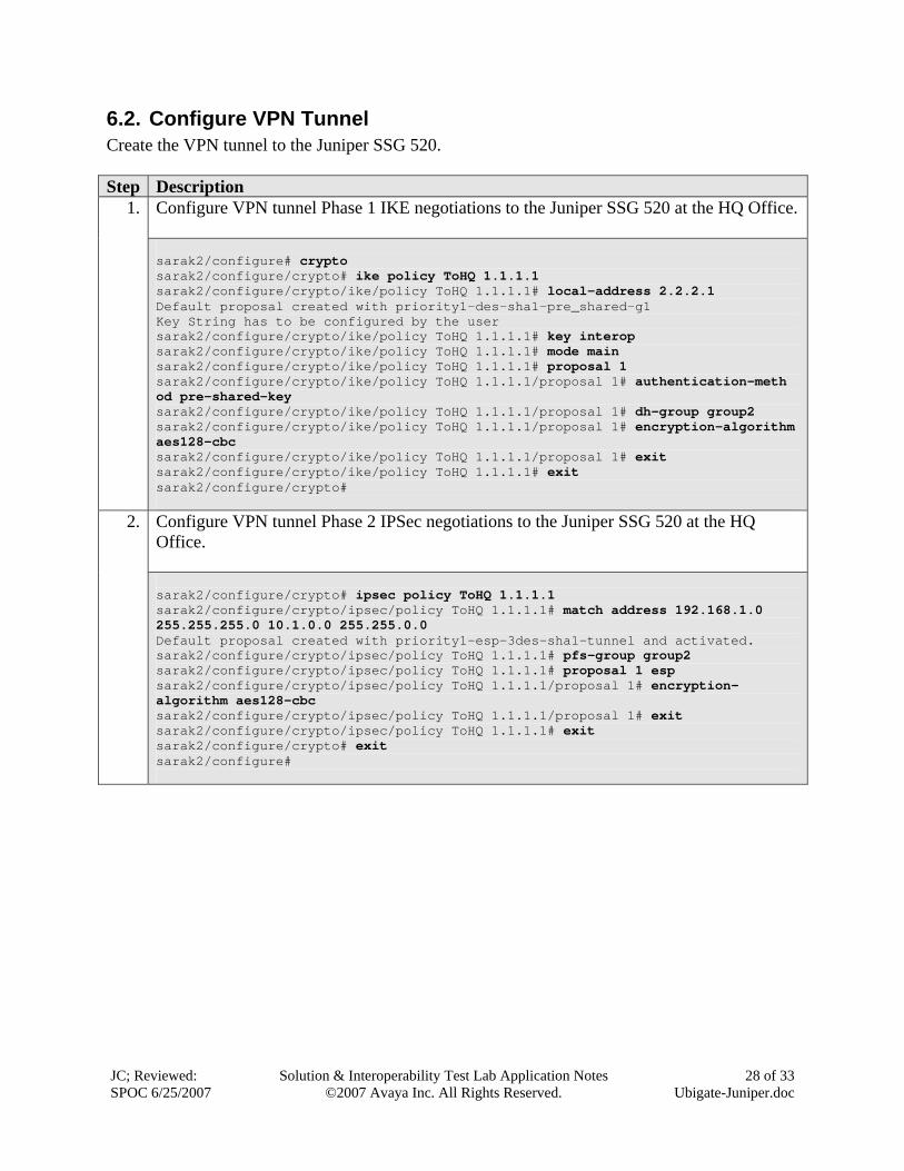
Configure VPN tunnel Phase 1 IKE negotiations to the Juniper SSG 520 at the HQ Office.
1.
sarak2/configure# crypto sarak2/configure/crypto# ike policy ToHQ 1.1.1.1 sarak2/configure/crypto/ike/policy ToHQ 1.1.1.1# local-address 2.2.2.1 Default proposal created with priority1-des-sha1-pre_shared-g1 Key String has to be configured by the user sarak2/configure/crypto/ike/policy ToHQ 1.1.1.1# key interop sarak2/configure/crypto/ike/policy ToHQ 1.1.1.1# mode main sarak2/configure/crypto/ike/policy ToHQ 1.1.1.1# proposal 1 sarak2/configure/crypto/ike/policy ToHQ 1.1.1.1/proposal 1# authentication-meth od pre-shared-key sarak2/configure/crypto/ike/policy ToHQ 1.1.1.1/proposal 1# dh-group group2 sarak2/configure/crypto/ike/policy ToHQ 1.1.1.1/proposal 1# encryption-algorithm aes128-cbc sarak2/configure/crypto/ike/policy ToHQ 1.1.1.1/proposal 1# exit sarak2/configure/crypto/ike/policy ToHQ 1.1.1.1# exit sarak2/configure/crypto#
Configure VPN tunnel Phase 2 IPSec negotiations to the Juniper SSG 520 at the HQ Office.
2.
sarak2/configure/crypto# ipsec policy ToHQ 1.1.1.1 sarak2/configure/crypto/ipsec/policy ToHQ 1.1.1.1# match address 192.168.1.0 255.255.255.0 10.1.0.0 255.255.0.0 Default proposal created with priority1-esp-3des-sha1-tunnel and activated. sarak2/configure/crypto/ipsec/policy ToHQ 1.1.1.1# pfs-group group2 sarak2/configure/crypto/ipsec/policy ToHQ 1.1.1.1# proposal 1 esp sarak2/configure/crypto/ipsec/policy ToHQ 1.1.1.1/proposal 1# encryption-algorithm aes128-cbc sarak2/configure/crypto/ipsec/policy ToHQ 1.1.1.1/proposal 1# exit sarak2/configure/crypto/ipsec/policy ToHQ 1.1.1.1# exit sarak2/configure/crypto# exit sarak2/configure#
JC; Reviewed: SPOC 6/25/2007
Solution & Interoperability Test Lab Application Notes ©2007 Avaya Inc. All Rights Reserved.
29 of 33 Ubigate-Juniper.doc
6.3. Configure Firewall Policies Configure the policies to allow traffic between the two sites across the VPN tunnel. Step Description
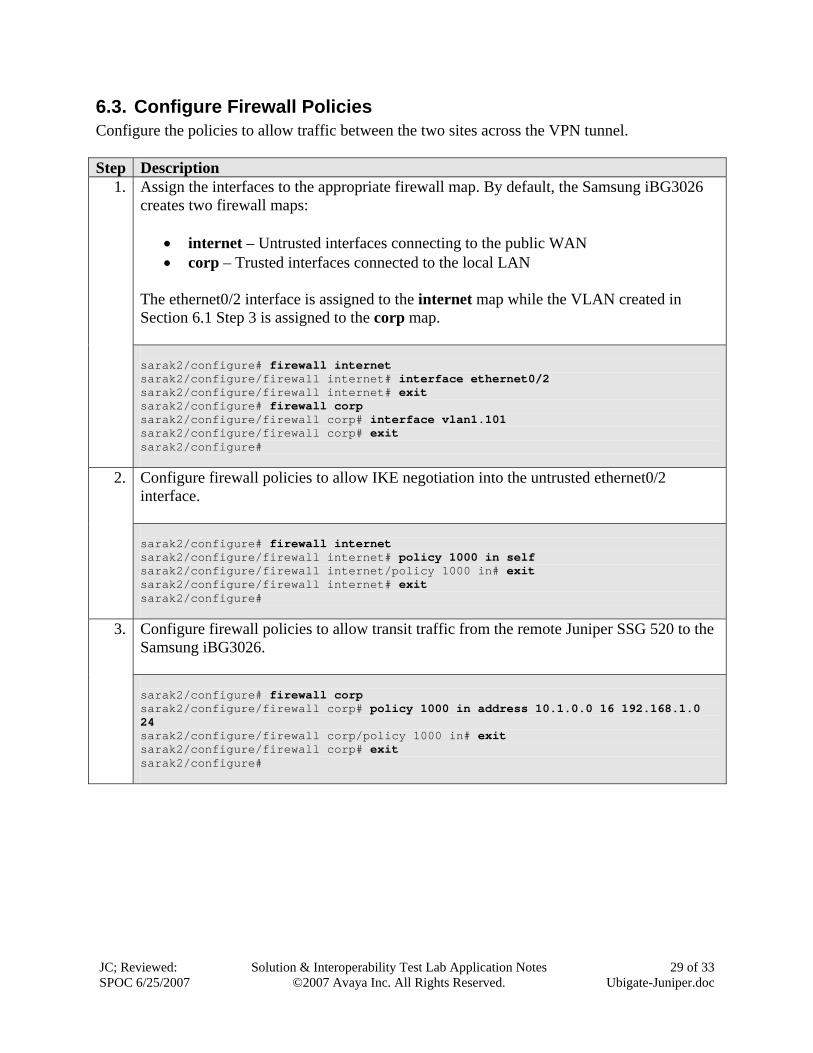
Assign the interfaces to the appropriate firewall map. By default, the Samsung iBG3026 creates two firewall maps:
• internet – Untrusted interfaces connecting to the public WAN • corp – Trusted interfaces connected to the local LAN
The ethernet0/2 interface is assigned to the internet map while the VLAN created in Section 6.1 Step 3 is assigned to the corp map.
1.
sarak2/configure# firewall internet sarak2/configure/firewall internet# interface ethernet0/2 sarak2/configure/firewall internet# exit sarak2/configure# firewall corp sarak2/configure/firewall corp# interface vlan1.101 sarak2/configure/firewall corp# exit sarak2/configure#
Configure firewall policies to allow IKE negotiation into the untrusted ethernet0/2 interface.
2.
sarak2/configure# firewall internet sarak2/configure/firewall internet# policy 1000 in self sarak2/configure/firewall internet/policy 1000 in# exit sarak2/configure/firewall internet# exit sarak2/configure#
Configure firewall policies to allow transit traffic from the remote Juniper SSG 520 to the Samsung iBG3026.
3.
sarak2/configure# firewall corp sarak2/configure/firewall corp# policy 1000 in address 10.1.0.0 16 192.168.1.0 24 sarak2/configure/firewall corp/policy 1000 in# exit sarak2/configure/firewall corp# exit sarak2/configure#
JC; Reviewed: SPOC 6/25/2007
Solution & Interoperability Test Lab Application Notes ©2007 Avaya Inc. All Rights Reserved.
30 of 33 Ubigate-Juniper.doc
6.4. Configure Quality of Service Configure the Samsung iBG3026 to prioritize voice traffic across the VPN tunnel. The Samsung iBG3026 supports both software-based QoS in the operating system and hardware-based QoS enforced in the chipset. In this configuration, software-based QoS is utilized to ensure the bandwidth allocated for voice traffic is guaranteed across the VPN tunnel. The Samsung iBG3026 QoS implements Random Early Detection (RED) to address congestion and Class Based Queuing (CBQ) to address traffic policing for bandwidth management. Step Description
Configure CBQ on the VPN interface. A class called voip is created to classify voice traffic and to assign QoS parameters for this class.
1.
sarak2/configure# crypto sarak2/configure/crypto# qos sarak2/configure/crypto/qos# add-policy-class voip root-out sarak2/configure/crypto/qos# add-policy-class default root-out sarak2/configure/crypto/qos# policy-class voip sarak2/configure/crypto/qos/policy-class voip# match-dscp 46 sarak2/configure/crypto/qos/policy-class voip# cbq cr-percent 25 pr-percent 50 priority 1 sarak2/configure/crypto/qos/policy-class voip# exit sarak2/configure/crypto/qos# policy-class default sarak2/configure/crypto/qos/policy-class default# match-dscp default sarak2/configure/crypto/qos/policy-class default# cbq cr-percent 50 pr-percent 75 priority 8 sarak2/configure/crypto/qos/policy-class default# exit sarak2/configure/crypto/qos# enable cbq sarak2/configure/crypto/qos# exit sarak2/configure/crypto# exit sarak2/configure#
7. Verification Steps The following steps can be used to verify that the configuration steps documented in these Application Notes have been done correctly.
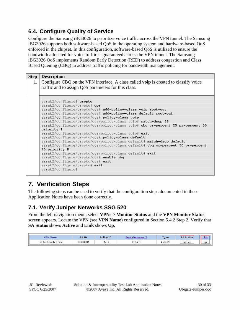
7.1. Verify Juniper Networks SSG 520 From the left navigation menu, select VPNs > Monitor Status and the VPN Monitor Status screen appears. Locate the VPN (see VPN Name) configured in Section 5.4.2 Step 2. Verify that SA Status shows Active and Link shows Up.
JC; Reviewed: SPOC 6/25/2007
Solution & Interoperability Test Lab Application Notes ©2007 Avaya Inc. All Rights Reserved.
31 of 33 Ubigate-Juniper.doc
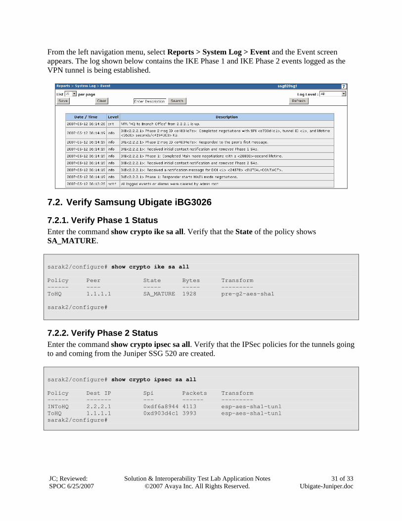
From the left navigation menu, select Reports > System Log > Event and the Event screen appears. The log shown below contains the IKE Phase 1 and IKE Phase 2 events logged as the VPN tunnel is being established.
7.2. Verify Samsung Ubigate iBG3026
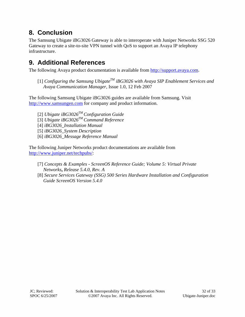
7.2.1. Verify Phase 1 Status Enter the command show crypto ike sa all. Verify that the State of the policy shows SA_MATURE. sarak2/configure# show crypto ike sa all Policy Peer State Bytes Transform ------ ---- ----- ----- --------- ToHQ 1.1.1.1 SA_MATURE 1928 pre-g2-aes-sha1 sarak2/configure#
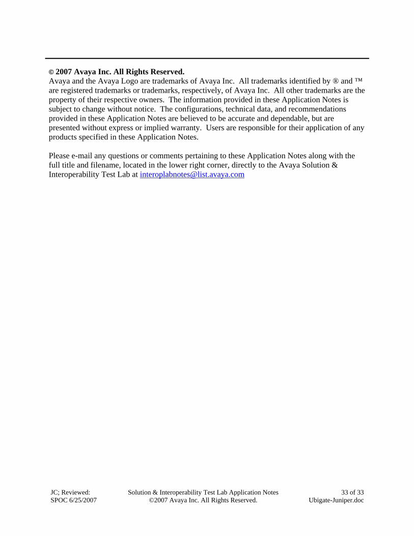
7.2.2. Verify Phase 2 Status Enter the command show crypto ipsec sa all. Verify that the IPSec policies for the tunnels going to and coming from the Juniper SSG 520 are created. sarak2/configure# show crypto ipsec sa all Policy Dest IP Spi Packets Transform ------ ------- --- ------ --------- INToHQ 2.2.2.1 0xdf6a8944 4113 esp-aes-sha1-tunl ToHQ 1.1.1.1 0xd903d4c1 3993 esp-aes-sha1-tunl sarak2/configure#
JC; Reviewed: SPOC 6/25/2007
Solution & Interoperability Test Lab Application Notes ©2007 Avaya Inc. All Rights Reserved.
32 of 33 Ubigate-Juniper.doc
8. Conclusion The Samsung Ubigate iBG3026 Gateway is able to interoperate with Juniper Networks SSG 520 Gateway to create a site-to-site VPN tunnel with QoS to support an Avaya IP telephony infrastructure.
9. Additional References The following Avaya product documentation is available from http://support.avaya.com.
[1] Configuring the Samsung UbigateTM iBG3026 with Avaya SIP Enablement Services and Avaya Communication Manager, Issue 1.0, 12 Feb 2007
The following Samsung Ubigate iBG3026 guides are available from Samsung. Visit http://www.samsungen.com for company and product information.
[2] Ubigate iBG3026TM Configuration Guide [3] Ubigate iBG3026TM Command Reference [4] iBG3026_Installation Manual [5] iBG3026_System Description [6] iBG3026_Message Reference Manual
The following Juniper Networks product documentations are available from http://www.juniper.net/techpubs/:
[7] Concepts & Examples - ScreenOS Reference Guide; Volume 5: Virtual Private Networks, Release 5.4.0, Rev. A
[8] Secure Services Gateway (SSG) 500 Series Hardware Installation and Configuration Guide ScreenOS Version 5.4.0
JC; Reviewed: SPOC 6/25/2007
Solution & Interoperability Test Lab Application Notes ©2007 Avaya Inc. All Rights Reserved.
33 of 33 Ubigate-Juniper.doc
© 2007 Avaya Inc. All Rights Reserved. Avaya and the Avaya Logo are trademarks of Avaya Inc. All trademarks identified by ® and ™ are registered trademarks or trademarks, respectively, of Avaya Inc. All other trademarks are the property of their respective owners. The information provided in these Application Notes is subject to change without notice. The configurations, technical data, and recommendations provided in these Application Notes are believed to be accurate and dependable, but are presented without express or implied warranty. Users are responsible for their application of any products specified in these Application Notes. Please e-mail any questions or comments pertaining to these Application Notes along with the full title and filename, located in the lower right corner, directly to the Avaya Solution & Interoperability Test Lab at [email protected]