Embed Size (px)
Citation preview
Product Bulletin Bulletin Number: P-2004-0129-NA Date: 05 April 2004 Configuring Cisco Quality of Service parameters to support Nortel Networks Voice over IP solutions Introduction Providing Quality of Service (QoS) for Voice over IP (VoIP) is a complex challenge given the variety of platforms and methods available. We at Nortel Networks have worked to make the task of designing and configuring QoS on our equipment as simple as possible. When a customer plans on deploying our VoIP products in a Cisco environment, this challenge becomes more difficult since Cisco has an extensive library of information available on deploying and configuring QoS on their devices where the focus is strictly on their platforms. The question that challenges the customer in this situation is “What is the Nortel Networks recommended configuration for QoS on my Cisco network so the Nortel Networks VoIP gear works properly”? This document is intended to help our customers make the correct choices when deploying Nortel Networks VoIP gear in a Cisco environment. The configuration examples are included as a reference as well as a template for the customer. This document is not intended to replace Cisco documentation nor the training necessary to configure and troubleshoot Cisco devices. It is assumed that the reader of this document is familiar with various QoS methods. This document doesn’t include every possible combination of hardware, software, LAN or WAN scenario This document contains tested Cisco configurations for different QoS techniques. These configurations are meant to be generic enough to be applied to most types of Cisco equipment. Please note that some Cisco equipment uses special processing such as Virtual Interface Processor (VIP), and as a result, may change the recommended configurations. Most QoS configurations will remain constant across different data WAN network protocols. But in some environments, this is not true. For this reason, this guide is divided into different WAN sections for HDLC, Frame Relay, and PPP. ATM configurations, and FR/ATM conversions, will be covered in a future document. In this document courier text indicates information entered into or responses from the Cisco router interface. Classification Methods Classification of traffic flows is the first step in providing QoS; all Nortel Networks VoIP products have the ability to classify traffic by marking the Differentiated Services Code Point (DSCP) or Type of Service (ToS) headers with a user specified setting. Not all Cisco devices have the ability to prioritize based on this field; this is where the complexity of the issue lies.
Nortel Networks Page 1 of 38
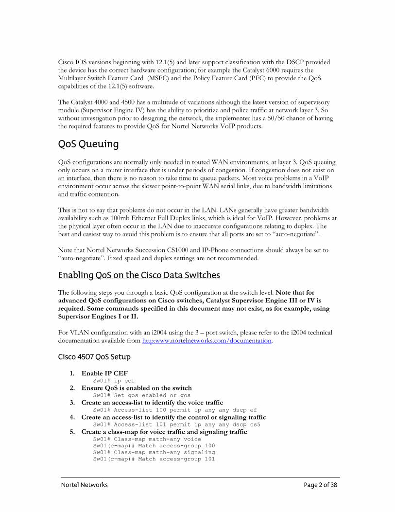
Cisco IOS versions beginning with 12.1(5) and later support classification with the DSCP provided the device has the correct hardware configuration; for example the Catalyst 6000 requires the Multilayer Switch Feature Card (MSFC) and the Policy Feature Card (PFC) to provide the QoS capabilities of the 12.1(5) software. The Catalyst 4000 and 4500 has a multitude of variations although the latest version of supervisory module (Supervisor Engine IV) has the ability to prioritize and police traffic at network layer 3. So without investigation prior to designing the network, the implementer has a 50/50 chance of having the required features to provide QoS for Nortel Networks VoIP products. QoS Queuing QoS configurations are normally only needed in routed WAN environments, at layer 3. QoS queuing only occurs on a router interface that is under periods of congestion. If congestion does not exist on an interface, then there is no reason to take time to queue packets. Most voice problems in a VoIP environment occur across the slower point-to-point WAN serial links, due to bandwidth limitations and traffic contention. This is not to say that problems do not occur in the LAN. LANs generally have greater bandwidth availability such as 100mb Ethernet Full Duplex links, which is ideal for VoIP. However, problems at the physical layer often occur in the LAN due to inaccurate configurations relating to duplex. The best and easiest way to avoid this problem is to ensure that all ports are set to “auto-negotiate”. Note that Nortel Networks Succession CS1000 and IP-Phone connections should always be set to “auto-negotiate”. Fixed speed and duplex settings are not recommended. Enabling QoS on the Cisco Data Switches The following steps you through a basic QoS configuration at the switch level. Note that for advanced QoS configurations on Cisco switches, Catalyst Supervisor Engine III or IV is required. Some commands specified in this document may not exist, as for example, using Supervisor Engines I or II. For VLAN configuration with an i2004 using the 3 – port switch, please refer to the i2004 technical documentation available from http:www.nortelnetworks.com/documentation. Cisco 4507 QoS Setup
1. Enable IP CEF Sw01# ip cef
2. Ensure QoS is enabled on the switch Sw01# Set qos enabled or qos
3. Create an access-list to identify the voice traffic Sw01# Access-list 100 permit ip any any dscp ef
4. Create an access-list to identify the control or signaling traffic Sw01# Access-list 101 permit ip any any dscp cs5
5. Create a class-map for voice traffic and signaling traffic Sw01# Class-map match-any voice Sw01(c-map)# Match access-group 100 Sw01# Class-map match-any signaling Sw01(c-map)# Match access-group 101
Nortel Networks Page 2 of 38
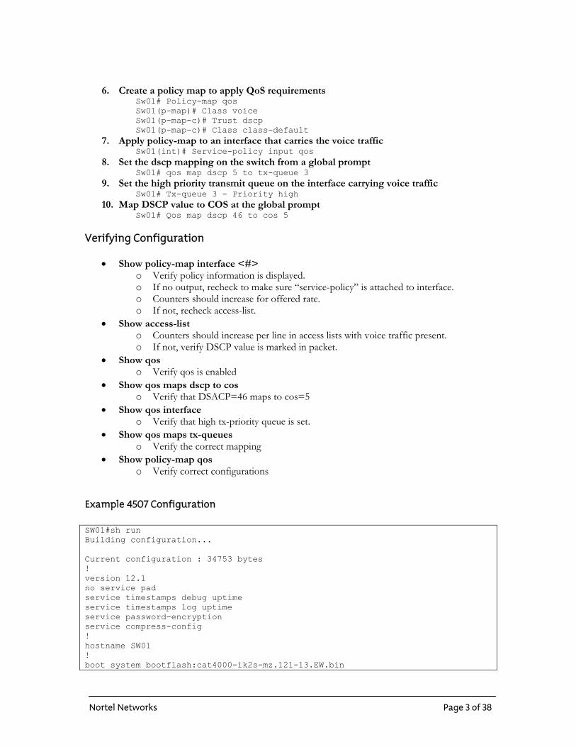
6. Create a policy map to apply QoS requirements Sw01# Policy-map qos Sw01(p-map)# Class voice Sw01(p-map-c)# Trust dscp Sw01(p-map-c)# Class class-default
7. Apply policy-map to an interface that carries the voice traffic Sw01(int)# Service-policy input qos
8. Set the dscp mapping on the switch from a global prompt Sw01# qos map dscp 5 to tx-queue 3
9. Set the high priority transmit queue on the interface carrying voice traffic Sw01# Tx-queue 3 - Priority high
10. Map DSCP value to COS at the global prompt Sw01# Qos map dscp 46 to cos 5
Verifying Configuration
• Show policy-map interface <#> o Verify policy information is displayed. o If no output, recheck to make sure “service-policy” is attached to interface. o Counters should increase for offered rate. o If not, recheck access-list.
• Show access-list o Counters should increase per line in access lists with voice traffic present. o If not, verify DSCP value is marked in packet.
• Show qos o Verify qos is enabled
• Show qos maps dscp to cos o Verify that DSACP=46 maps to cos=5
• Show qos interface o Verify that high tx-priority queue is set.
• Show qos maps tx-queues o Verify the correct mapping
• Show policy-map qos o Verify correct configurations
Example 4507 Configuration SW01#sh run Building configuration... Current configuration : 34753 bytes ! version 12.1 no service pad service timestamps debug uptime service timestamps log uptime service password-encryption service compress-config ! hostname SW01 ! boot system bootflash:cat4000-ik2s-mz.121-13.EW.bin
Nortel Networks Page 3 of 38
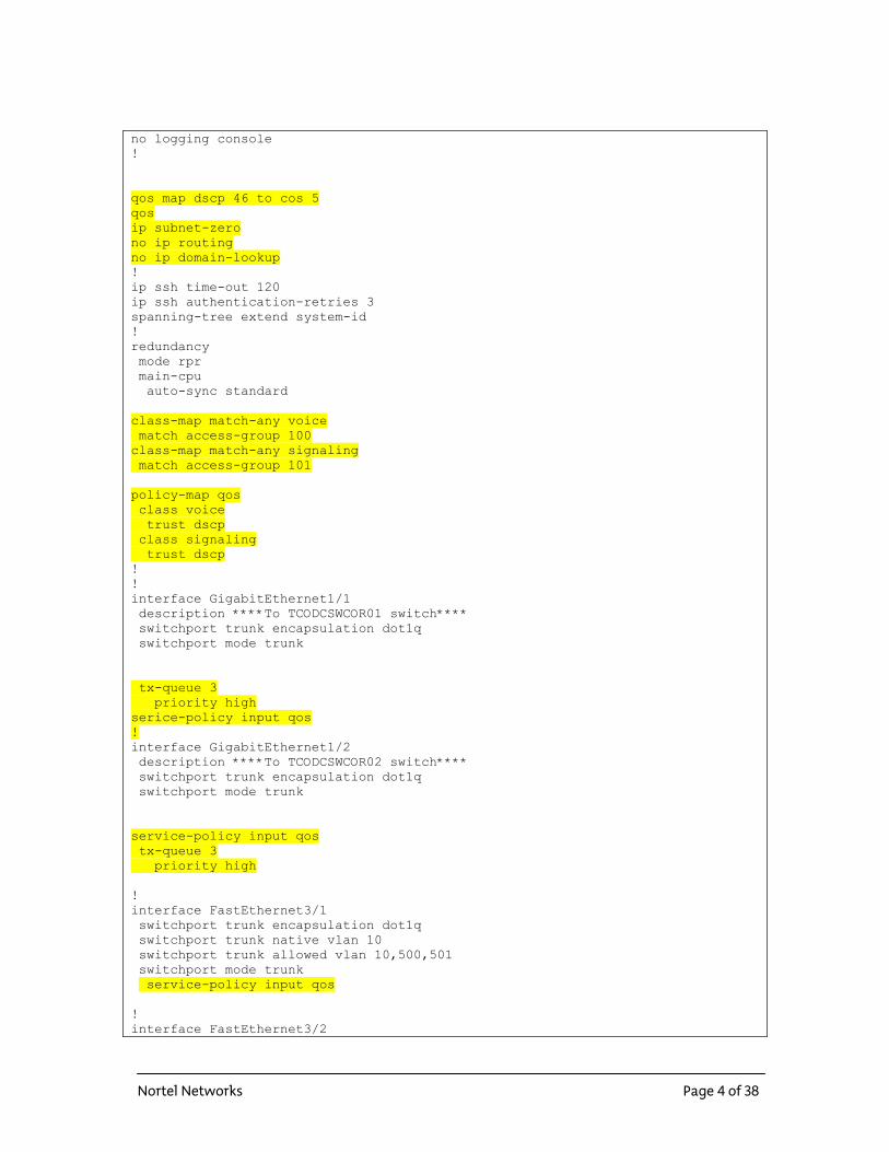
no logging console ! qos map dscp 46 to cos 5 qos ip subnet-zero no ip routing no ip domain-lookup ! ip ssh time-out 120 ip ssh authentication-retries 3 spanning-tree extend system-id ! redundancy mode rpr main-cpu auto-sync standard class-map match-any voice match access-group 100 class-map match-any signaling match access-group 101 policy-map qos class voice trust dscp class signaling trust dscp ! ! interface GigabitEthernet1/1 description ****To TCODCSWCOR01 switch**** switchport trunk encapsulation dot1q switchport mode trunk tx-queue 3 priority high serice-policy input qos ! interface GigabitEthernet1/2 description ****To TCODCSWCOR02 switch**** switchport trunk encapsulation dot1q switchport mode trunk service-policy input qos tx-queue 3 priority high ! interface FastEthernet3/1 switchport trunk encapsulation dot1q switchport trunk native vlan 10 switchport trunk allowed vlan 10,500,501 switchport mode trunk service-policy input qos ! interface FastEthernet3/2
Nortel Networks Page 4 of 38
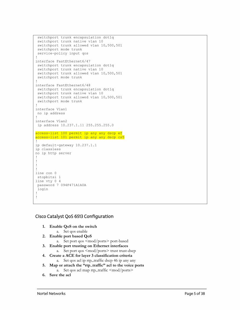
switchport trunk encapsulation dot1q switchport trunk native vlan 10 switchport trunk allowed vlan 10,500,501 switchport mode trunk service-policy input qos ! interface FastEthernet6/47 switchport trunk encapsulation dot1q switchport trunk native vlan 10 switchport trunk allowed vlan 10,500,501 switchport mode trunk ! interface FastEthernet6/48 switchport trunk encapsulation dot1q switchport trunk native vlan 10 switchport trunk allowed vlan 10,500,501 switchport mode trunk ! interface Vlan1 no ip address ! interface Vlan2 ip address 10.237.1.11 255.255.255.0 access-list 100 permit ip any any dscp ef access-list 101 permit ip any any dscp cs5 ! ip default-gateway 10.237.1.1 ip classless no ip http server ! ! ! ! line con 0 stopbitsi 1 line vty 0 4 password 7 094F471A1A0A login ! ! Cisco Catalyst QoS 6513 Configuration
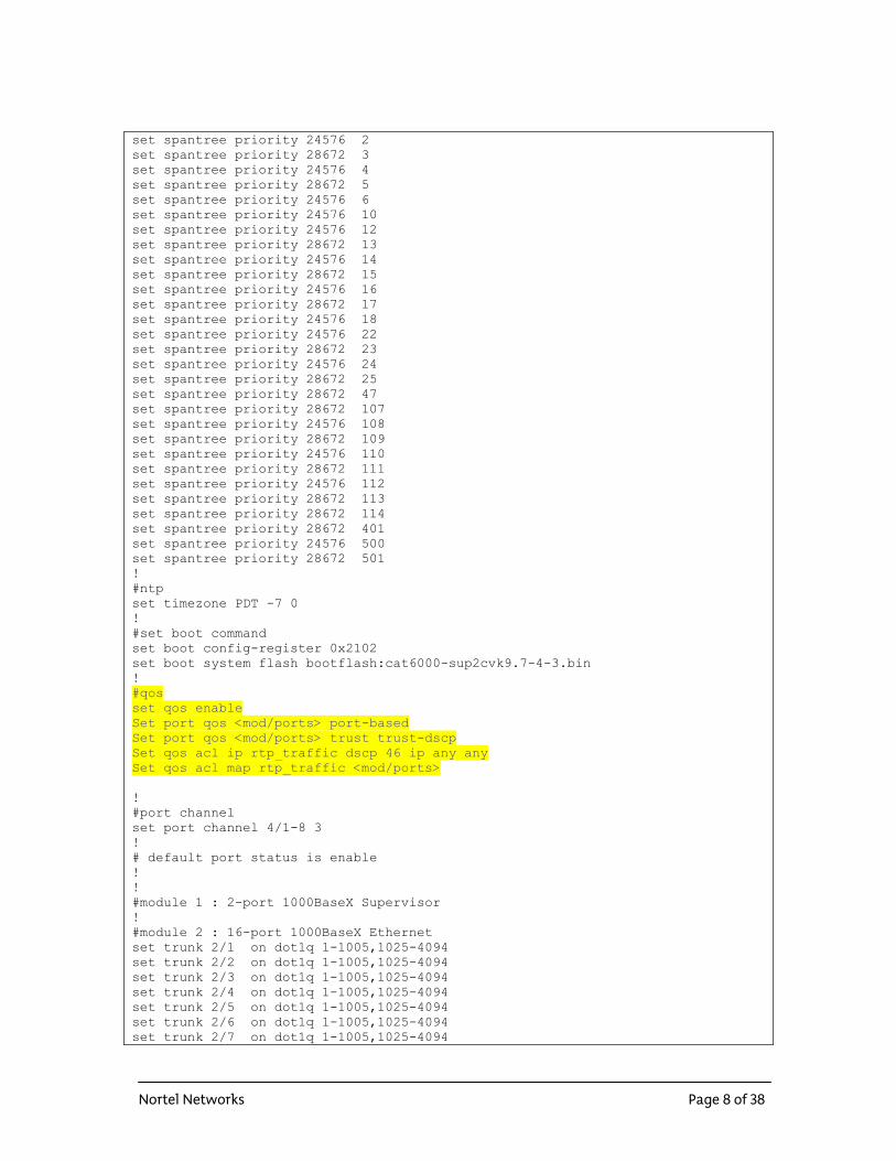
1. Enable QoS on the switch a. Set qos enable
2. Enable port based QoS a. Set port qos <mod/ports> port-based
3. Enable port trusting on Ethernet interfaces a. Set port qos <mod/ports> trust trust-dscp
4. Create a ACE for layer 3 classification criteria a. Set qos acl ip rtp_traffic dscp 46 ip any any
5. Map or attach the “rtp_traffic” acl to the voice ports a. Set qos acl map rtp_traffic <mod/ports>
6. Save the acl
Nortel Networks Page 5 of 38
a. Commit qos acl rtp_traffic
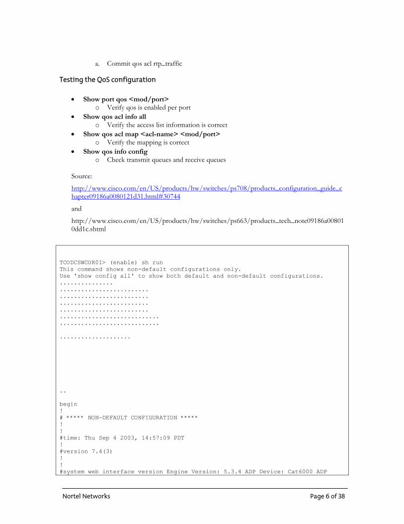
Testing the QoS configuration
• Show port qos <mod/port> o Verify qos is enabled per port
• Show qos acl info all o Verify the access list information is correct
• Show qos acl map <acl-name> <mod/port> o Verify the mapping is correct
• Show qos info config o Check transmit queues and receive queues
Source:
http://www.cisco.com/en/US/products/hw/switches/ps708/products_configuration_guide_chapter09186a0080121d31.html#30744
and
http://www.cisco.com/en/US/products/hw/switches/ps663/products_tech_note09186a008010dd1c.shtml
TCODCSWCOR01> (enable) sh run This command shows non-default configurations only. Use 'show config all' to show both default and non-default configurations. ............... ......................... ......................... ......................... ......................... ............................ ............................ .................... .. begin ! # ***** NON-DEFAULT CONFIGURATION ***** ! ! #time: Thu Sep 4 2003, 14:57:09 PDT ! #version 7.4(3) ! ! #system web interface version Engine Version: 5.3.4 ADP Device: Cat6000 ADP
Nortel Networks Page 6 of 38
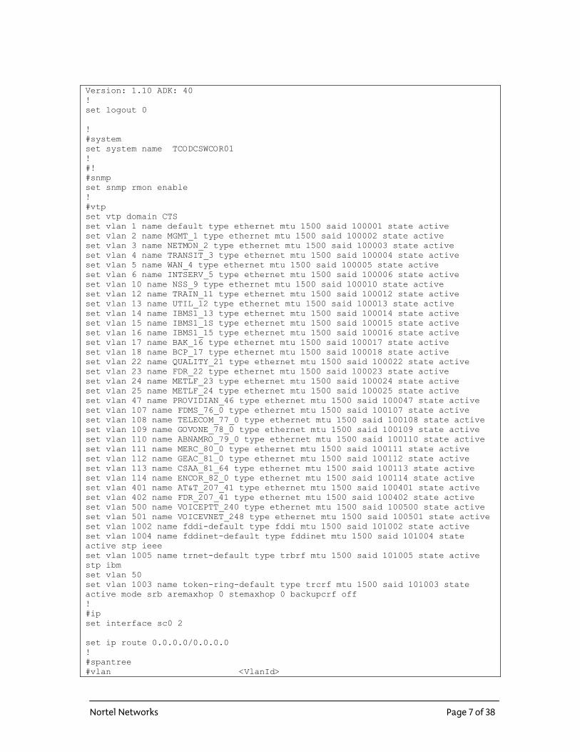
Version: 1.10 ADK: 40 ! set logout 0 ! #system set system name TCODCSWCOR01 ! #! #snmp set snmp rmon enable ! #vtp set vtp domain CTS set vlan 1 name default type ethernet mtu 1500 said 100001 state active set vlan 2 name MGMT_1 type ethernet mtu 1500 said 100002 state active set vlan 3 name NETMON_2 type ethernet mtu 1500 said 100003 state active set vlan 4 name TRANSIT_3 type ethernet mtu 1500 said 100004 state active set vlan 5 name WAN_4 type ethernet mtu 1500 said 100005 state active set vlan 6 name INTSERV_5 type ethernet mtu 1500 said 100006 state active set vlan 10 name NSS_9 type ethernet mtu 1500 said 100010 state active set vlan 12 name TRAIN_11 type ethernet mtu 1500 said 100012 state active set vlan 13 name UTIL_12 type ethernet mtu 1500 said 100013 state active set vlan 14 name IBMS1_13 type ethernet mtu 1500 said 100014 state active set vlan 15 name IBMS1_1S type ethernet mtu 1500 said 100015 state active set vlan 16 name IBMS1_15 type ethernet mtu 1500 said 100016 state active set vlan 17 name BAK_16 type ethernet mtu 1500 said 100017 state active set vlan 18 name BCP_17 type ethernet mtu 1500 said 100018 state active set vlan 22 name QUALITY_21 type ethernet mtu 1500 said 100022 state active set vlan 23 name FDR_22 type ethernet mtu 1500 said 100023 state active set vlan 24 name METLF_23 type ethernet mtu 1500 said 100024 state active set vlan 25 name METLF_24 type ethernet mtu 1500 said 100025 state active set vlan 47 name PROVIDIAN_46 type ethernet mtu 1500 said 100047 state active set vlan 107 name FDMS_76_0 type ethernet mtu 1500 said 100107 state active set vlan 108 name TELECOM_77_0 type ethernet mtu 1500 said 100108 state active set vlan 109 name GOVONE_78_0 type ethernet mtu 1500 said 100109 state active set vlan 110 name ABNAMRO_79_0 type ethernet mtu 1500 said 100110 state active set vlan 111 name MERC_80_0 type ethernet mtu 1500 said 100111 state active set vlan 112 name GEAC_81_0 type ethernet mtu 1500 said 100112 state active set vlan 113 name CSAA_81_64 type ethernet mtu 1500 said 100113 state active set vlan 114 name ENCOR_82_0 type ethernet mtu 1500 said 100114 state active set vlan 401 name AT&T_207_41 type ethernet mtu 1500 said 100401 state active set vlan 402 name FDR_207_41 type ethernet mtu 1500 said 100402 state active set vlan 500 name VOICEPTT_240 type ethernet mtu 1500 said 100500 state active set vlan 501 name VOICEVNET_248 type ethernet mtu 1500 said 100501 state active set vlan 1002 name fddi-default type fddi mtu 1500 said 101002 state active set vlan 1004 name fddinet-default type fddinet mtu 1500 said 101004 state active stp ieee set vlan 1005 name trnet-default type trbrf mtu 1500 said 101005 state active stp ibm set vlan 50 set vlan 1003 name token-ring-default type trcrf mtu 1500 said 101003 state active mode srb aremaxhop 0 stemaxhop 0 backupcrf off ! #ip set interface sc0 2 set ip route 0.0.0.0/0.0.0.0 ! #spantree #vlan <VlanId>
Nortel Networks Page 7 of 38
set spantree priority 24576 2 set spantree priority 28672 3 set spantree priority 24576 4 set spantree priority 28672 5 set spantree priority 24576 6 set spantree priority 24576 10 set spantree priority 24576 12 set spantree priority 28672 13 set spantree priority 24576 14 set spantree priority 28672 15 set spantree priority 24576 16 set spantree priority 28672 17 set spantree priority 24576 18 set spantree priority 24576 22 set spantree priority 28672 23 set spantree priority 24576 24 set spantree priority 28672 25 set spantree priority 28672 47 set spantree priority 28672 107 set spantree priority 24576 108 set spantree priority 28672 109 set spantree priority 24576 110 set spantree priority 28672 111 set spantree priority 24576 112 set spantree priority 28672 113 set spantree priority 28672 114 set spantree priority 28672 401 set spantree priority 24576 500 set spantree priority 28672 501 ! #ntp set timezone PDT -7 0 ! #set boot command set boot config-register 0x2102 set boot system flash bootflash:cat6000-sup2cvk9.7-4-3.bin ! #qos set qos enable Set port qos <mod/ports> port-based Set port qos <mod/ports> trust trust-dscp Set qos acl ip rtp_traffic dscp 46 ip any any Set qos acl map rtp_traffic <mod/ports> ! #port channel set port channel 4/1-8 3 ! # default port status is enable ! ! #module 1 : 2-port 1000BaseX Supervisor ! #module 2 : 16-port 1000BaseX Ethernet set trunk 2/1 on dot1q 1-1005,1025-4094 set trunk 2/2 on dot1q 1-1005,1025-4094 set trunk 2/3 on dot1q 1-1005,1025-4094 set trunk 2/4 on dot1q 1-1005,1025-4094 set trunk 2/5 on dot1q 1-1005,1025-4094 set trunk 2/6 on dot1q 1-1005,1025-4094 set trunk 2/7 on dot1q 1-1005,1025-4094
Nortel Networks Page 8 of 38
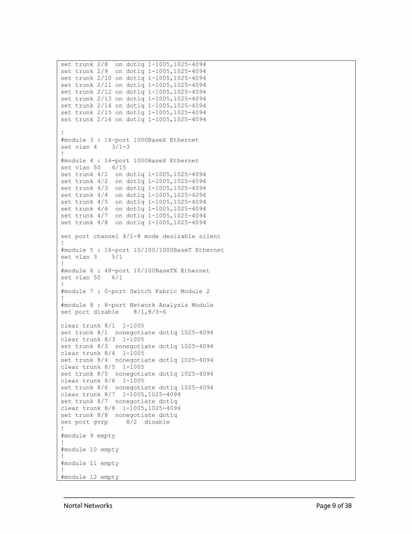
set trunk 2/8 on dot1q 1-1005,1025-4094 set trunk 2/9 on dot1q 1-1005,1025-4094 set trunk 2/10 on dot1q 1-1005,1025-4094 set trunk 2/11 on dot1q 1-1005,1025-4094 set trunk 2/12 on dot1q 1-1005,1025-4094 set trunk 2/13 on dot1q 1-1005,1025-4094 set trunk 2/14 on dot1q 1-1005,1025-4094 set trunk 2/15 on dot1q 1-1005,1025-4094 set trunk 2/16 on dot1q 1-1005,1025-4094 ! #module 3 : 16-port 1000BaseX Ethernet set vlan 4 3/1-3 ! #module 4 : 16-port 1000BaseX Ethernet set vlan 50 4/15 set trunk 4/1 on dot1q 1-1005,1025-4094 set trunk 4/2 on dot1q 1-1005,1025-4094 set trunk 4/3 on dot1q 1-1005,1025-4094 set trunk 4/4 on dot1q 1-1005,1025-4094 set trunk 4/5 on dot1q 1-1005,1025-4094 set trunk 4/6 on dot1q 1-1005,1025-4094 set trunk 4/7 on dot1q 1-1005,1025-4094 set trunk 4/8 on dot1q 1-1005,1025-4094 set port channel 4/1-8 mode desirable silent ! #module 5 : 16-port 10/100/1000BaseT Ethernet set vlan 3 5/1 ! #module 6 : 48-port 10/100BaseTX Ethernet set vlan 50 6/1 ! #module 7 : 0-port Switch Fabric Module 2 ! #module 8 : 8-port Network Analysis Module set port disable 8/1,8/3-6 clear trunk 8/1 1-1005 set trunk 8/1 nonegotiate dot1q 1025-4094 clear trunk 8/3 1-1005 set trunk 8/3 nonegotiate dot1q 1025-4094 clear trunk 8/4 1-1005 set trunk 8/4 nonegotiate dot1q 1025-4094 clear trunk 8/5 1-1005 set trunk 8/5 nonegotiate dot1q 1025-4094 clear trunk 8/6 1-1005 set trunk 8/6 nonegotiate dot1q 1025-4094 clear trunk 8/7 1-1005,1025-4094 set trunk 8/7 nonegotiate dot1q clear trunk 8/8 1-1005,1025-4094 set trunk 8/8 nonegotiate dot1q set port gvrp 8/2 disable ! #module 9 empty ! #module 10 empty ! #module 11 empty ! #module 12 empty
Nortel Networks Page 9 of 38
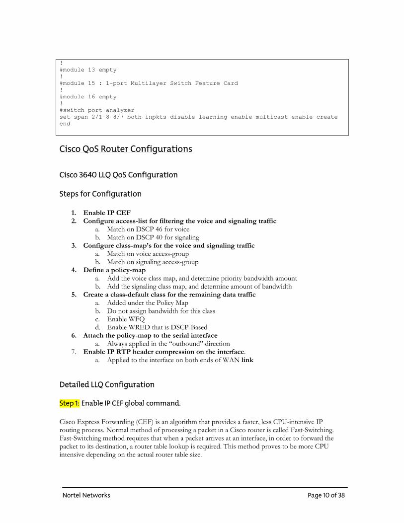
! #module 13 empty ! #module 15 : 1-port Multilayer Switch Feature Card ! #module 16 empty ! #switch port analyzer set span 2/1-8 8/7 both inpkts disable learning enable multicast enable create end Cisco QoS Router Configurations
Cisco 3640 LLQ QoS Configuration
Steps for Configuration
1. Enable IP CEF 2. Configure access-list for filtering the voice and signaling traffic
a. Match on DSCP 46 for voice b. Match on DSCP 40 for signaling
3. Configure class-map’s for the voice and signaling traffic a. Match on voice access-group b. Match on signaling access-group
4. Define a policy-map a. Add the voice class map, and determine priority bandwidth amount b. Add the signaling class map, and determine amount of bandwidth
5. Create a class-default class for the remaining data traffic a. Added under the Policy Map b. Do not assign bandwidth for this class c. Enable WFQ d. Enable WRED that is DSCP-Based
6. Attach the policy-map to the serial interface a. Always applied in the “outbound” direction
7. Enable IP RTP header compression on the interface. a. Applied to the interface on both ends of WAN link
Detailed LLQ Configuration
Step 1: Enable IP CEF global command. Cisco Express Forwarding (CEF) is an algorithm that provides a faster, less CPU-intensive IP routing process. Normal method of processing a packet in a Cisco router is called Fast-Switching. Fast-Switching method requires that when a packet arrives at an interface, in order to forward the packet to its destination, a router table lookup is required. This method proves to be more CPU intensive depending on the actual router table size.
Nortel Networks Page 10 of 38
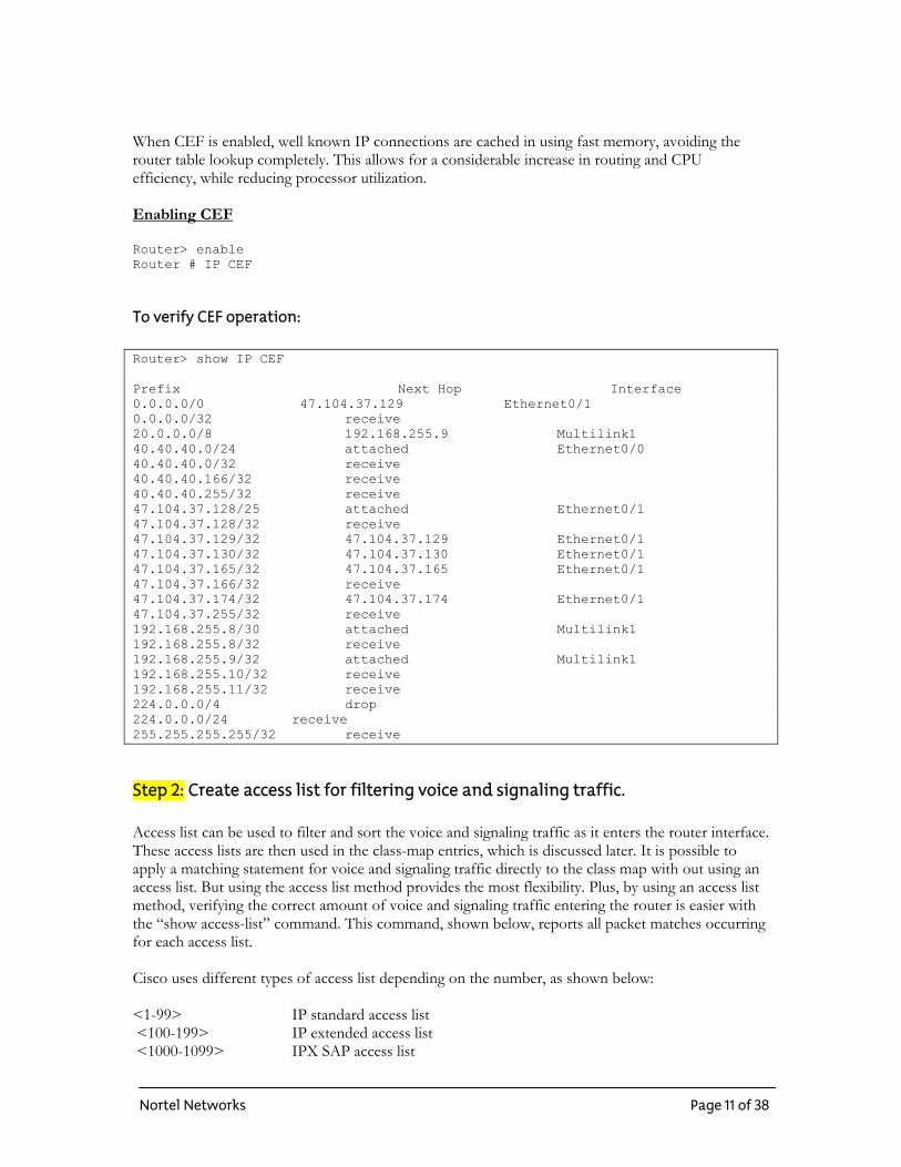
When CEF is enabled, well known IP connections are cached in using fast memory, avoiding the router table lookup completely. This allows for a considerable increase in routing and CPU efficiency, while reducing processor utilization. Enabling CEF Router> enable Router # IP CEF
To verify CEF operation: Router> show IP CEF Prefix Next Hop Interface 0.0.0.0/0 47.104.37.129 Ethernet0/1 0.0.0.0/32 receive 20.0.0.0/8 192.168.255.9 Multilink1 40.40.40.0/24 attached Ethernet0/0 40.40.40.0/32 receive 40.40.40.166/32 receive 40.40.40.255/32 receive 47.104.37.128/25 attached Ethernet0/1 47.104.37.128/32 receive 47.104.37.129/32 47.104.37.129 Ethernet0/1 47.104.37.130/32 47.104.37.130 Ethernet0/1 47.104.37.165/32 47.104.37.165 Ethernet0/1 47.104.37.166/32 receive 47.104.37.174/32 47.104.37.174 Ethernet0/1 47.104.37.255/32 receive 192.168.255.8/30 attached Multilink1 192.168.255.8/32 receive 192.168.255.9/32 attached Multilink1 192.168.255.10/32 receive 192.168.255.11/32 receive 224.0.0.0/4 drop 224.0.0.0/24 receive 255.255.255.255/32 receive
Step 2: Create access list for filtering voice and signaling traffic. Access list can be used to filter and sort the voice and signaling traffic as it enters the router interface. These access lists are then used in the class-map entries, which is discussed later. It is possible to apply a matching statement for voice and signaling traffic directly to the class map with out using an access list. But using the access list method provides the most flexibility. Plus, by using an access list method, verifying the correct amount of voice and signaling traffic entering the router is easier with the “show access-list” command. This command, shown below, reports all packet matches occurring for each access list. Cisco uses different types of access list depending on the number, as shown below: <1-99> IP standard access list <100-199> IP extended access list <1000-1099> IPX SAP access list
Nortel Networks Page 11 of 38
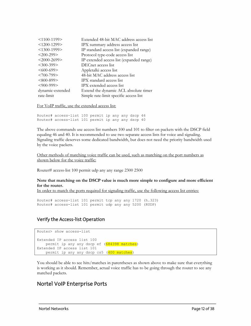
<1100-1199> Extended 48-bit MAC address access list <1200-1299> IPX summary address access list <1300-1999> IP standard access list (expanded range) <200-299> Protocol type-code access list <2000-2699> IP extended access list (expanded range) <300-399> DECnet access list <600-699> Appletalki access list <700-799> 48-bit MAC address access list <800-899> IPX standard access list <900-999> IPX extended access list dynamic-extended Extend the dynamic ACL absolute timer rate-limit Simple rate-limit specific access list For VoIP traffic, use the extended access list: Router# access-list 100 permit ip any any dscp 46 Router# access-list 101 permit ip any any dscp 40
The above commands use access list numbers 100 and 101 to filter on packets with the DSCP field equaling 46 and 40. It is recommended to use two separate access lists for voice and signaling. Signaling traffic deserves some dedicated bandwidth, but does not need the priority bandwidth used by the voice packets. Other methods of matching voice traffic can be used, such as matching on the port numbers as shown below for the voice traffic: Router# access-list 100 permit udp any any range 2300 2500 Note that matching on the DSCP value is much more simple to configure and more efficient for the router. In order to match the ports required for signaling traffic, use the following access list entries: Router# access-list 101 permit tcp any any 1720 (h.323) Router# access-list 101 permit udp any any 5200 (RUDP)
Verify the Access-list Operation Router> show access-list Extended IP access list 100 permit ip any any dscp ef (684398 matches) Extended IP access list 101 permit ip any any dscp cs5 (400 matches)
You should be able to see hits/matches in parentheses as shown above to make sure that everything is working as it should. Remember, actual voice traffic has to be going through the router to see any matched packets. Nortel VoIP Enterprise Ports
Nortel Networks Page 12 of 38
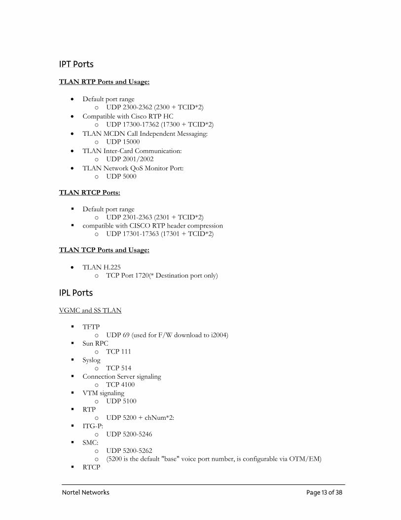
IPT Ports TLAN RTP Ports and Usage:
• Default port range o UDP 2300-2362 (2300 + TCID*2)
• Compatible with Cisco RTP HC o UDP 17300-17362 (17300 + TCID*2)
• TLAN MCDN Call Independent Messaging: o UDP 15000
• TLAN Inter-Card Communication: o UDP 2001/2002
• TLAN Network QoS Monitor Port: o UDP 5000
TLAN RTCP Ports:
Default port range o UDP 2301-2363 (2301 + TCID*2)
compatible with CISCO RTP header compression o UDP 17301-17363 (17301 + TCID*2)
TLAN TCP Ports and Usage:
• TLAN H.225 o TCP Port 1720(* Destination port only)
IPL Ports VGMC and SS TLAN
TFTP o UDP 69 (used for F/W download to i2004)
Sun RPC o TCP 111
Syslog o TCP 514
Connection Server signaling o TCP 4100
VTM signaling o UDP 5100
RTP o UDP 5200 + chNum*2:
ITG-P: o UDP 5200-5246
SMC: o UDP 5200-5262 o (5200 is the default "base" voice port number, is configurable via OTM/EM)
RTCP
Nortel Networks Page 13 of 38
o UDP5200 + chNum*2 +1 ITG-P
o UDP 5200-5247, SMC: 5201-5263 o (indirectly programmable - based on RTP port)
TPS (Node Manager) signaling (with sets) o UDP 7300
TPS signaling (with other cards) o UDP 16543
SNTP Server o TCP 20000+node id o (e.g. Node 001 has SNTP server port 20001)
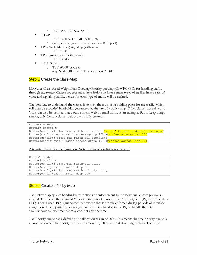
Step 3: Create the Class-Map LLQ uses Class-Based Weight Fair Queuing/Priority queuing (CBWFQ/PQ) for handling traffic through the router. Classes are created to help isolate or filter certain types of traffic. In the case of voice and signaling traffic, a class for each type of traffic will be defined. The best way to understand the classes is to view them as just a holding place for the traffic, which will then be provided bandwidth guarantees by the use of a policy map. Other classes not related to VoIP can also be defined that would contain web or email traffic as an example. But to keep things simple, only the two classes below are initially created: Router> enable Router# config t Router(config)# class-map match-all voice (“voice” is just a descriptive name) Router(config-cmap)# match access-group 100 (matches access-list 100) Router(config)# class-map match-all signaling Router(config-cmap)# match access-group 101 (matches access-list 101)
Alternate Class-map Configuration: Note that an access list is not needed. Router> enable Router# config t Router(config)# class-map match-all voice Router(config-cmap)# match dscp ef Router(config)# class-map match-all signaling Router(config-cmap)# match dscp cs5
Step 4: Create a Policy Map The Policy Map applies bandwidth restrictions or enforcement to the individual classes previously created. The use of the keyword “priority” indicates the use of the Priority Queue (PQ), and specifies LLQ is being used. PQ is guaranteed bandwidth that is strictly enforced during periods of interface congestion. It is important the enough bandwidth is allocated in the PQ to handle the total, simultaneous call volume that may occur at any one time. The Priority queue has a default burst allocation assign of 20%. This means that the priority queue is allowed to exceed the priority bandwidth amount by 20%, without dropping packets. The burst
Nortel Networks Page 14 of 38
amount is displayed in “bytes”. In order to understand the amount in “kbps”, multiply the “bytes” amount by 8. Example: Bandwidth is 200kps, then Burst would be 5000 bytes (20%) Actual burst amount in “kbps” would be 40kbps, providing a total PQ bandwidth at any one time of 200kbps + 40Kbps = 240kbps It is important to note that only during periods of congestion does the PQ allocate this bandwidth. If the PQ allocated bandwidth is exceeded during periods of congestion, all excess packets will be dropped. The keyword “bandwidth” in the other classes indicates a guaranteed bandwidth, but is not a “Priority” bandwidth which is used for the voice packets. This class bandwidth allocation is not as critical in the amount allocated, and will make use of other available bandwidth that exists in the default class if it is exceeded. This type of bandwidth is used for the signaling traffic as described below. Note that all descriptive names for the policy and classes are case-sensitive. So keeping the names simple, and all lower case helps prevent typographic errors. Router(config)# policy-map voip Router(config-pmap)# class voice Router(config-pmap-c)# priority 500 (PQ = 500kbps) Router(config-pmap)# class signaling Router(config-pmap-c)# bandwidth 20 (guaranteed bandwidth of 20kbps) Router(config-pmap)# class class-default (this class is created here) Router(config-pmap-c)# fair-queueing (enables WFQ) Router(config-pmap-c)# random-detect dscp-based (enables WRED) All remaining traffic that is not defined in the class-maps will fall into the “class-default” class. This is a catch-all class that uses Weighted Fair Queuing (WFQ), and Weighted Random Early Detection (WRED). WFQ will help share the available bandwidth evenly amongst the traffic flows in the default class. As a result, a particular type of traffic can not dominate all the available bandwidth. WRED is a congestion avoidance algorithm that purposely drops packets in order to avoid interface congestion. Both commands, WFQ and WRED, should only be applied to the default-class.
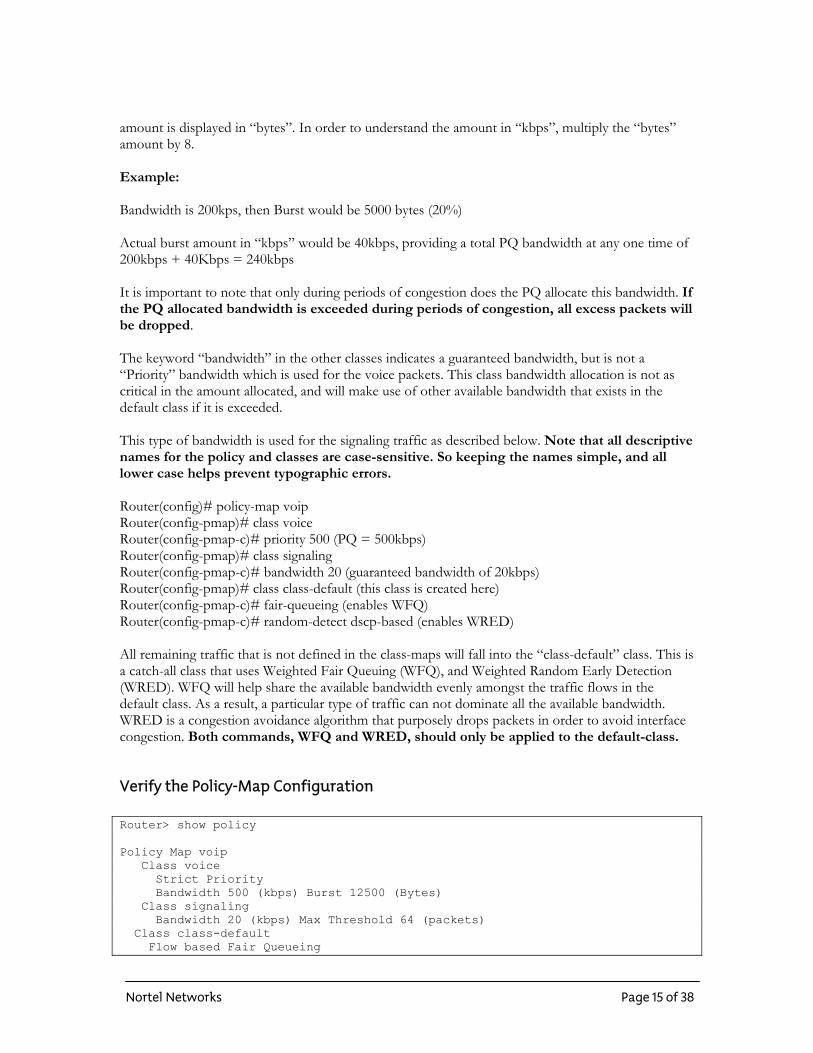
Verify the Policy-Map Configuration Router> show policy Policy Map voip Class voice Strict Priority Bandwidth 500 (kbps) Burst 12500 (Bytes) Class signaling Bandwidth 20 (kbps) Max Threshold 64 (packets) Class class-default Flow based Fair Queueing
Nortel Networks Page 15 of 38

Bandwidth 0 (kbps) exponential weight 9 dscp min-threshold max-threshold mark-probability ---------------------------------------------------------- af11 - - 1/10 af12 - - 1/10 af13 - - 1/10 af21 - - 1/10 af22 - - 1/10 af23 - - 1/10 af31 - - 1/10 af32 - - 1/10 af33 - - 1/10 af41 - - 1/10 af42 - - 1/10 af43 - - 1/10 cs1 - - 1/10 cs2 - - 1/10 cs3 - - 1/10 cs4 - - 1/10 cs5 - - 1/10 cs6 - - 1/10 cs7 - - 1/10 ef - - 1/10 rsvp - - 1/10 default - - 1/10
The above output reflects the Policy configuration currently configured in the router. Notice that the voice class is using “strict priority” set to 500kbps, and is allowed to burst 20% or 12500 bytes (100kbps) for a total of 600kbps. This Policy only takes in effect when the interface is under congestion. The Class “Class-default” is using “flow-based fair-queuing”. This type of queuing was enabled with the keywords “random-detect DSCP-Based”. This only applies to the “class-default”. All traffic flows in this class will be shared evenly using the WFQ algorithm. The Random Detect (WRED) algorithm will drop packets based on the DSCP value only. In the “class-default” class, all available class of services is listed. This listing only applies for the traffic that exists in the “default class”. It is common not to see the voice or signaling packets using class of service “EF” and “CS5” in the counters. Remember that the voice and signaling traffic is provisioned in a completely separate queue for priority and guaranteed bandwidth.
Step 5: Assign the Policy Map to an Interface So far, the policy is still not actively doing anything with the voice and signaling traffic on the interfaces. The policy map must be applied to an interface using the “service-policy” command. It is possible to apply the policy to any physical or logical interface, in an outbound or inbound direction. But the normal configuration for Layer – 3 QoS is to apply to the serial interfaces only, in the outbound direction. Router# config t Router(config)# interface s1 Router(config-if)# service-policy output voip
Nortel Networks Page 16 of 38
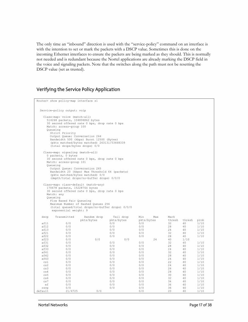
The only time an “inbound” direction is used with the “service-policy” command on an interface is with the intention to set or mark the packets with a DSCP value. Sometimes this is done on the incoming Ethernet interfaces to ensure the packets are being marked as they should. This is normally not needed and is redundant because the Nortel applications are already marking the DSCP field in the voice and signaling packets. Note that the switches along the path must not be resetting the DSCP value (set as trusted).
Verifying the Service Policy Application Router> show policy-map interface s1 Service-policy output: voip Class-map: voice (match-all) 514268 packets, 104894862 bytes 30 second offered rate 0 bps, drop rate 0 bps Match: access-group 100 Queueing Strict Priority Output Queue: Conversation 264 Bandwidth 500 (kbps) Burst 12500 (Bytes) (pkts matched/bytes matched) 263131/53668339 (total drops/bytes drops) 0/0 Class-map: signaling (match-all) 0 packets, 0 bytes 30 second offered rate 0 bps, drop rate 0 bps Match: access-group 101 Queueing Output Queue: Conversation 265 Bandwidth 20 (kbps) Max Threshold 64 (packets) (pkts matched/bytes matched) 0/0 (depth/total drops/no-buffer drops) 0/0/0 Class-map: class-default (match-any) 170678 packets, 15228744 bytes 30 second offered rate 0 bps, drop rate 0 bps Match: any Queueing Flow Based Fair Queueing Maximum Number of Hashed Queues 256 (total queued/total drops/no-buffer drops) 0/0/0 exponential weight: 9 dscp Transmitted Random drop Tail drop Min Max Mark pkts/bytes pkts/bytes pkts/bytes thresh thresh prob af11 0/0 0/0 0/0 32 40 1/10 af12 0/0 0/0 0/0 28 40 1/10 af13 0/0 0/0 0/0 24 40 1/10 af21 0/0 0/0 0/0 32 40 1/10 af22 0/0 0/0 0/0 28 40 1/10 af23 0/0 0/0 0/0 24 40 1/10 af31 0/0 0/0 0/0 32 40 1/10 af32 0/0 0/0 0/0 28 40 1/10 af33 0/0 0/0 0/0 24 40 1/10 af41 0/0 0/0 0/0 32 40 1/10 af42 0/0 0/0 0/0 28 40 1/10 af43 0/0 0/0 0/0 24 40 1/10 cs1 0/0 0/0 0/0 22 40 1/10 cs2 0/0 0/0 0/0 24 40 1/10 cs3 0/0 0/0 0/0 26 40 1/10 cs4 0/0 0/0 0/0 28 40 1/10 cs5 0/0 0/0 0/0 30 40 1/10 cs6 0/0 0/0 0/0 32 40 1/10 cs7 0/0 0/0 0/0 34 40 1/10 ef 0/0 0/0 0/0 36 40 1/10 rsvp 0/0 0/0 0/0 36 40 1/10 default 21/4725 0/0 0/0 20 40 1/10
Nortel Networks Page 17 of 38
If the service policy is working as it should, an output like what shown above should appear. If this output does not show, then recheck the configuration, and verify that all the steps are completed. Often it is the policy map application to the interface using the “service-policy” command that gets missed during the configuration. The above output displays a very effective way to verify that the different classes are working as they should. It might be necessary to change the load reporting stats on the interface in order to see a more responsive report (use keyword “load 30” on the interface). By default, the load is set to 5 minutes. To verify that in the voice class, only voice traffic exists generate only a single call across the WAN link at G.711 at 10ms for example, and recheck the voice class output using the “show policy-map interface” command. This command may need to be re-run until the output rate seems to stabilize on a single bandwidth amount. For the one call at g.711 across a PPP link, with no VAD, or HC, the output should be about 100kbps throughput. Note that if VAD (Voice Activity Detection) or QoS probing (IPT) is enabled, actual reported bandwidth per call could be different. VAD suppresses the background noise in a conversation, and only transmits the actual voice packets as speech occurs. QoS probing is a fail-over feature in ITG-Trunk applications that generates about 15kbps extra bandwidth for the probe packets. Note that the probe packets also use the same DSCP value as the actual voice packets. Under the default-class output, only counters that should increase should be for the class of services “default”. If a routing protocol such as OSPF and EIGRP is used in the data network, then the class of serve “CS6” will increment. If the counters are increasing for the class of service “CS5” or “EF” under the “default-class”, then the policy map has been corrupted and the router will need to be rebooted to correct this problem. Sometimes this happens when the policy or access list have been modified with existing voice traffic occurring on the interface. Older IOS versions are susceptible to policy modifications in this way. What this means is that the router is placing all traffic in the default class, even the voice packets that are suppose to be filtered into a priority class. Rebooting the router normally solves this problem by resetting the physical interface buffers. In order to prevent this problem from reoccurring, an upgrade to the IOS is needed to the latest release.
Step 6: Enable RTP Header-Compression Enabling cRTP allows you to conserve the amount of bandwidth per call. A voice packet uses RTP RFC 1889 protocol for transport of real-time data. The IP/UDP/RTP header combination equals 40 bytes. With cRTP, the header combination is reduced to approximately 2 to 5 bytes (RFC 2508). Note: Do not use the “passive” version of this command. “Passive” only works with packets already compressed. Router(config)#int s1 Router(config-if)# ip rtp header-compression iphc-format
Nortel Networks Page 18 of 38
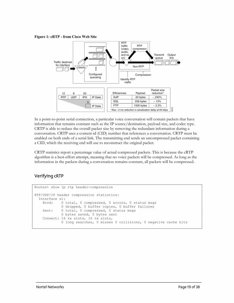
Figure 1: cRTP - from Cisco Web Site
In a point-to-point serial connection, a particular voice conversation will contain packets that have information that remains constant such as the IP source/destination, payload size, and codec type. CRTP is able to reduce the overall packet size by removing the redundant information during a conversation. CRTP uses a content-id (CID) number that references a conversation. CRTP must be enabled on both ends of a serial link. The transmitting end sends an uncompressed packet containing a CID, which the receiving end will use to reconstruct the original packet. CRTP statistics report a percentage value of actual compressed packets. This is because the cRTP algorithm is a best-effort attempt, meaning that no voice packets will be compressed. As long as the information in the packets during a conversation remains constant, all packets will be compressed.
Verifying cRTP Router> show ip rtp header-compression RTP/UDP/IP header compression statistics: Interface s1: Rcvd: 0 total, 0 compressed, 0 errors, 0 status msgs 0 dropped, 0 buffer copies, 0 buffer failures Sent: 0 total, 0 compressed, 0 status msgs 0 bytes saved, 0 bytes sent Connect: 16 rx slots, 16 tx slots, 0 long searches, 0 misses 0 collisions, 0 negative cache hits
Nortel Networks Page 19 of 38
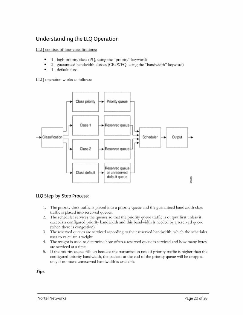
Understanding the LLQ Operation LLQ consists of four classifications:
1 - high-priority class (PQ, using the “priority” keyword) 2 - guaranteed bandwidth classes (CB/WFQ, using the “bandwidth” keyword) 1 - default class
LLQ operation works as follows:
LLQ Step-by-Step Process:
1. The priority class traffic is placed into a priority queue and the guaranteed bandwidth class traffic is placed into reserved queues.
2. The scheduler services the queues so that the priority queue traffic is output first unless it exceeds a configured priority bandwidth and this bandwidth is needed by a reserved queue (when there is congestion).
3. The reserved queues are serviced according to their reserved bandwidth, which the scheduler uses to calculate a weight.
4. The weight is used to determine how often a reserved queue is serviced and how many bytes are serviced at a time.
5. If the priority queue fills up because the transmission rate of priority traffic is higher than the configured priority bandwidth, the packets at the end of the priority queue will be dropped only if no more unreserved bandwidth is available.
Tips:
Nortel Networks Page 20 of 38
• None of the reserved queues are restricted to the configured bandwidth if bandwidth is available.
• Packets violating the guaranteed bandwidth and priority are dropped only during congestion.
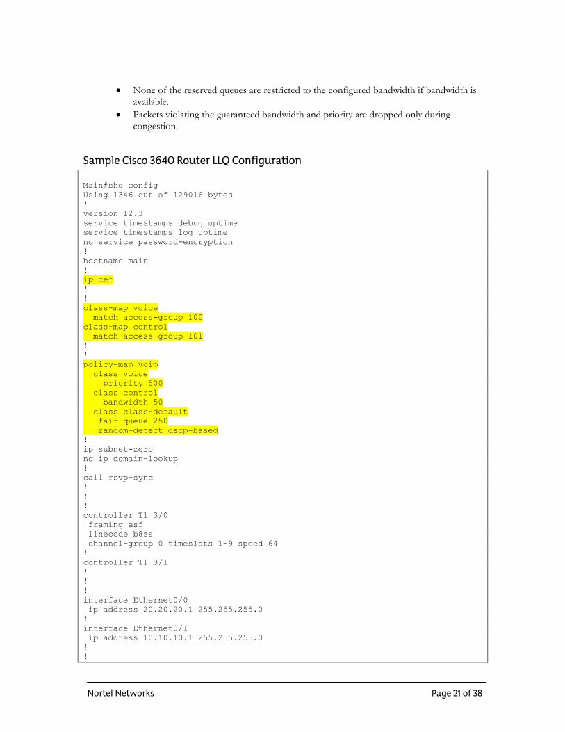
Sample Cisco 3640 Router LLQ Configuration Main#sho config Using 1346 out of 129016 bytes ! version 12.3 service timestamps debug uptime service timestamps log uptime no service password-encryption ! hostname main ! ip cef ! ! class-map voice match access-group 100 class-map control match access-group 101 ! ! policy-map voip class voice priority 500 class control bandwidth 50 class class-default fair-queue 250 random-detect dscp-based ! ip subnet-zero no ip domain-lookup ! call rsvp-sync ! ! ! controller T1 3/0 framing esf linecode b8zs channel-group 0 timeslots 1-9 speed 64 ! controller T1 3/1 ! ! ! interface Ethernet0/0 ip address 20.20.20.1 255.255.255.0 ! interface Ethernet0/1 ip address 10.10.10.1 255.255.255.0 ! !
Nortel Networks Page 21 of 38
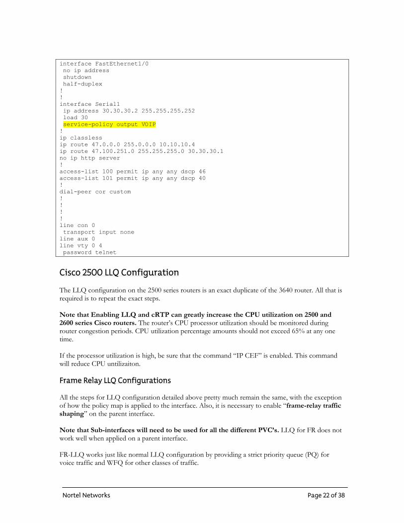
interface FastEthernet1/0 no ip address shutdown half-duplex ! ! interface Serial1 ip address 30.30.30.2 255.255.255.252 load 30 service-policy output VOIP ! ip classless ip route 47.0.0.0 255.0.0.0 10.10.10.4 ip route 47.100.251.0 255.255.255.0 30.30.30.1 no ip http server ! access-list 100 permit ip any any dscp 46 access-list 101 permit ip any any dscp 40 ! dial-peer cor custom ! ! ! ! line con 0 transport input none line aux 0 line vty 0 4 password telnet
Cisco 2500 LLQ Configuration The LLQ configuration on the 2500 series routers is an exact duplicate of the 3640 router. All that is required is to repeat the exact steps. Note that Enabling LLQ and cRTP can greatly increase the CPU utilization on 2500 and 2600 series Cisco routers. The router’s CPU processor utilization should be monitored during router congestion periods. CPU utilization percentage amounts should not exceed 65% at any one time. If the processor utilization is high, be sure that the command “IP CEF” is enabled. This command will reduce CPU untilizaiton. Frame Relay LLQ Configurations All the steps for LLQ configuration detailed above pretty much remain the same, with the exception of how the policy map is applied to the interface. Also, it is necessary to enable “frame-relay traffic shaping” on the parent interface. Note that Sub-interfaces will need to be used for all the different PVC’s. LLQ for FR does not work well when applied on a parent interface. FR-LLQ works just like normal LLQ configuration by providing a strict priority queue (PQ) for voice traffic and WFQ for other classes of traffic.
Nortel Networks Page 22 of 38
Rules for using LLQ on FR interfaces:
Must be used in combination with FRTS (traffic shaping). Queues are set on a per PVC basis. Fair queues are assigned weights proportional to the bandwidth requirements of each class. Over-subscribing or bursting above CIR is not allowed on converge voice and data PVC’s. Service policy must be applied to a “map-class” If fragmentation is used, it must be enabled on both ends of the serial link. Sub-interfaces are required for the different PVC’s
Note: LLQ for FR requires some basic understanding of FR concepts. This section provides a brief overview on these concepts but is not intended to be a complete training on FR. Frame Relay Traffic Shaping Traffic shaping is a mechanism that restricts traffic going out an interface to a particular speed, at the same time attempting to buffer bursts in excess of this maximum speed. Traffic shaping acts to “smooth out” or “shape” traffic into a stream that conforms to downstream requirements. Two methods used: GTS and FRTS GTS:
o Generic Traffic Shaping acts to limit packet rates sent out an interface to a CIR (Committed Information Rate: Total data sent on an average.) while allowing for buffering of momentary bursts.
FRTS:
o Frame Relay Traffic Shaping works like GTS, but allows queuing on a per VC basis (PQ & CQ), use of ACL’s, and Rate enforcement on a per VC basis.
Generic Traffic Shaping Parameters configured to match the Network architecture allows downstream congestion to be avoided, eliminating bottlenecks in the topologies with data-rate mismatches. GTS characteristics:
Rate enforcement per interface or sub-interface basis (can set the rate equal to the CIR). Traffic selection using ACL’s. Works on many layer 2 interface types, including FR, ATM, and Ethernet. Supports BECN messages for bandwidth throttling. Supports WFQ per interface.
Frame Relay and the “Token Bucket” Other queuing methods discussed use the “leaky bucket” method. FR Traffic Shaping uses the “token bucket” method which rate-limits traffic. A token bucket is different than a leaky bucket in
Nortel Networks Page 23 of 38
that rather than storing “packets”, it stores, or fills “tokens”. Tokens are like permission credits for a specific number of bits to be transmitted to the network at any one time. Token bucket is often referred as a “credit manager” that gives credit to traffic to be used for transmission:
1. Before a packet is sent, a certain number of tokens need to be removed from the bucket. 2. Tokens fill the token bucket at a constant rate, and the bucket is of a certain size. 3. After the bucket is full, new arriving tokens are discarded. 4. If the bucket is empty, an incoming packet has to wait for enough tokens to fill the bucket
before it can be transferred. Note that with a token bucket analogy, the burst size is roughly proportional to the size of the bucket.
Token Bucket Primary Variables There are three primary variables associated with the Token Bucket traffic shaping.
Mean Rate: Specifies how much data can be sent on average. Also called “CIR”. Burst Size: Specifies how much data can be sent over a single time interval without causing
scheduling problems. Also called “Committed Burst size”. Time Interval: This is the time quantum for a single burst. This is also called the
measurement interval. The burst size is the amount of data that can be sent to the token bucket over a single time interval. The mean rate is the burst size divided by the time interval. When a token bucket is regulating an output interface, its rate over a period of time can not exceed the mean rate. However, within that interval, the bit rate may be randomly fast. In this way, large data flows are regulated down to what the network can actually handle, and momentary bursts are smoothed out by buffering, rather than being dropped.
GTS Token Bucket Works with the Token Bucket algorithm.
1. When a packet arrives at the router, and interrupts occurs. 2. If the queue is empty, GTS consults the credit manager (token bucket) to see if there is
enough credit to send the packet. 3. If not enough credit, the packet will be sent to the queue configured, such as WFQ. 4. If there is enough credit, the packet will be sent to the output interface and the associated
credit value is deducted from the token bucket. 5. Queued packets are serviced at regular time intervals. 6. The credit manager is checked each time interval to determine if there is enough credit to
transmit the next packet waiting in the queue. 7. If there is, the packet is sent to the output interface and the VC is charged the appropriate
number of credits.
Nortel Networks Page 24 of 38
FRTS Algorithm FRTS works essentially the same as GTS.
Makes use of the “token bucket”, or “credit manager” algorithm to service the main queuing
mechanism and send packets out the interface. Not limited to one queuing method for the whole interface. Useful to overcome data-rate mismatches, typical with point to multipoint serial links. Enabled at the hub location
FRTS Characteristics:
Enhanced queuing support on a per VC basis. Traffic selection using ACL’s. Rate enforcement on a per VC basis. Supports both BECN and Cisco Foresight congestions notification on a per VC basis.
Nortel Networks Page 25 of 38
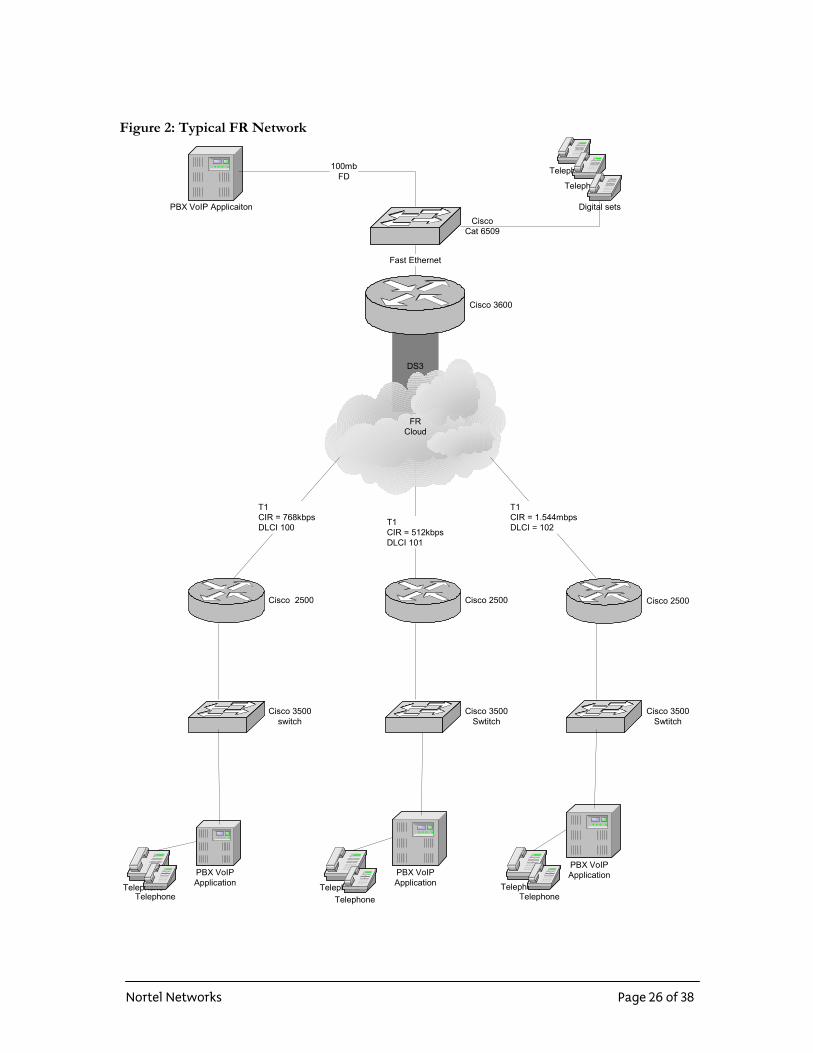
Figure 2: Typical FR Network
DS3
FRCloud
Cisco 3600
Cisco 3500switch
Cisco 2500 Cisco 2500 Cisco 2500
Cisco 3500Swtitch
Cisco 3500Swtitch
CiscoCat 6509
PBX VoIP Applicaiton
PBX VoIPApplication
PBX VoIPApplication
PBX VoIPApplication
TelephoneTelephone
TelephoneTelephone
TelephoneTelephone
Fast Ethernet
100mbFD
Telephone
Telephone
Digital sets
T1CIR = 768kbpsDLCI 100 T1
CIR = 512kbpsDLCI 101
T1CIR = 1.544mbpsDLCI = 102
Nortel Networks Page 26 of 38
Steps for LLQ –FR Configuration These steps remain the same as the previous HDLC configuration.
1. Configure ACL’s:
access-list 100 permit ip any any dscp 46 access-list 101 permit ip any any dscp 40
2. Configure Class Maps:
class-map voice match access-group 100 class-map control match access-group 101 !
3. Configure Policy-Map:
policy-map voip class voice priority 500 class control bandwidth 50 class class-default fair-queue random-detect dscp-based
Appling the “service-policy” on the interface is handled through the traffic shaping feature using a “map-class”. This is different from the HDLC configuration where the “service-policy” is attached directly to the interface.
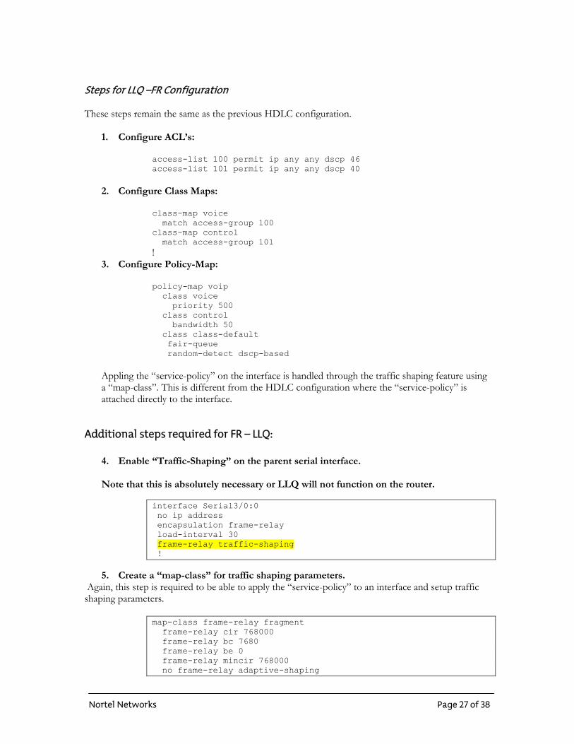
Additional steps required for FR – LLQ: 4. Enable “Traffic-Shaping” on the parent serial interface. Note that this is absolutely necessary or LLQ will not function on the router.
interface Serial3/0:0 no ip address encapsulation frame-relay load-interval 30 frame-relay traffic-shaping !
5. Create a “map-class” for traffic shaping parameters.
Again, this step is required to be able to apply the “service-policy” to an interface and setup traffic shaping parameters.
map-class frame-relay fragment frame-relay cir 768000 frame-relay bc 7680 frame-relay be 0 frame-relay mincir 768000 no frame-relay adaptive-shaping
Nortel Networks Page 27 of 38
service-policy output voip frame-relay fragment 768
Understanding Traffic Shaping Parameters
CIR: Committed Information Rate. o The average bit rate to send out the interface.
Bc: Committed bursts. o Number of bits to transmit in the specified amount of time interval. (Tc)
Be: Excess bursts. o Number of bits to transmit in the first interval of active transmission, once the
credit is built up. MinCir:
o Minimum amount of data to be sent during periods of congestion. o Defaults to half of CIR.
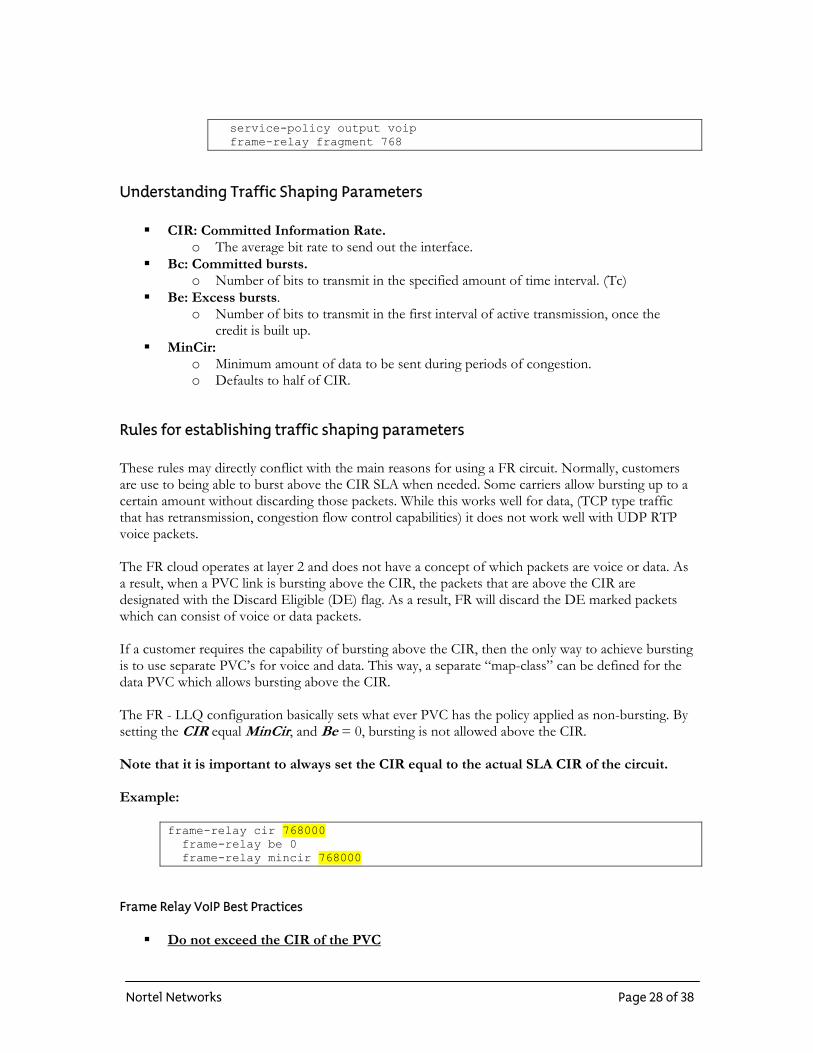
Rules for establishing traffic shaping parameters These rules may directly conflict with the main reasons for using a FR circuit. Normally, customers are use to being able to burst above the CIR SLA when needed. Some carriers allow bursting up to a certain amount without discarding those packets. While this works well for data, (TCP type traffic that has retransmission, congestion flow control capabilities) it does not work well with UDP RTP voice packets. The FR cloud operates at layer 2 and does not have a concept of which packets are voice or data. As a result, when a PVC link is bursting above the CIR, the packets that are above the CIR are designated with the Discard Eligible (DE) flag. As a result, FR will discard the DE marked packets which can consist of voice or data packets. If a customer requires the capability of bursting above the CIR, then the only way to achieve bursting is to use separate PVC’s for voice and data. This way, a separate “map-class” can be defined for the data PVC which allows bursting above the CIR. The FR - LLQ configuration basically sets what ever PVC has the policy applied as non-bursting. By setting the CIR equal MinCir, and Be = 0, bursting is not allowed above the CIR. Note that it is important to always set the CIR equal to the actual SLA CIR of the circuit. Example:
frame-relay cir 768000 frame-relay be 0 frame-relay mincir 768000
Frame Relay VoIP Best Practices
Do not exceed the CIR of the PVC
Nortel Networks Page 28 of 38
o Queuing of voice packets must be minimized. o If CIR is exceeded, packets will normally be queued in the FR cloud. o Maintain value at or below CIR on the PVC.
Do not use Frame Relay adaptive shaping o Adaptive shaping uses BECN to throttle down traffic if CIR is exceeded.
Set the Bc value low so Tc or the shaping interval is small (Tc = Bc/CIR) o Minimum configurable Tc value is 10ms. o Small value ensures that large packets do not use up all the available credits. o Large Tc values can lead to large gaps between packets sent because the traffic
shaper waits an entire Tc period to build up additional credits to send the next frame.
Set Be = zero o To ensure the CIR value is not exceeded, Be is set to zero so there are no excess
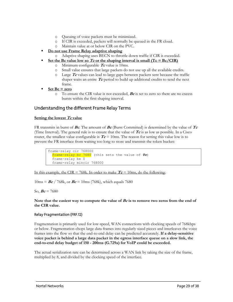
bursts within the first shaping interval. Understanding the different Frame Relay Terms Setting the lowest Tc value FR transmits in burst of Bc. The amount of Bc (Burst Committed) is determined by the value of Tc (Time Interval). The general rule is to ensure that the value of Tc is as low as possible. In a Cisco router, the smallest value configurable is Tc = 10ms. The reason for setting this value low is to prevent the FR interface from waiting too long to store and transmit the token bucket:
frame-relay cir 768000 frame-relay bc 7680 (this sets the value of Tc) frame-relay be 0 frame-relay mincir 768000
In this example, the CIR = 768k. In order to make Tc = 10ms, do the following: 10ms = Bc / 768k, or Bc = 10ms (768k), which equals 7680 So, Bc = 7680 Note that the easiest way to compute the value of Bc is to remove two zeros from the end of the CIR value. Relay Fragmentation (FRF.12) Fragmentation is primarily used for low-speed, WAN connections with clocking speeds of 768kbps or below. Fragmentation chops large data frames into regularly sized pieces and interleaves the voice frames into the flow so that the end-to-end delay can be predicted accurately. If a delay-sensitive voice packet is behind a large data packet in the egress interface queue on a slow link, the end-to-end delay budget of 150 - 200ms (G.729a) for VoIP could be exceeded. The actual serialization rate can be determined across a WAN link by taking the size of the frame, multiplied by 8, and divided by the clocking speed of the interface.
Nortel Networks Page 29 of 38
As an example: A 1500-byte frame takes 214ms to serialize on a 56kbps circuit.
(Serialization delay = (1500bytes * 8bits/byte) / (56k) In order to control the end-to-end delay and to prevent large data packets from affecting the smaller voice packets, fragmentation is required. Fragmentation is enabled under the “map-class” when using FR encapsulation. To determine the ideal fragment size, you can use the following recommendation: Recommended Fragment size:
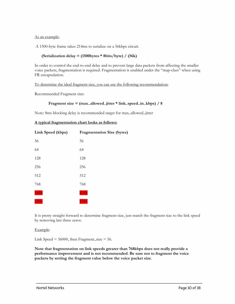
Fragment size = (max_allowed_jitter * link_speed_in_kbps) / 8 Note: 8ms blocking delay is recommended target for max_allowed_jitter A typical fragmentation chart looks as follows: Link Speed (kbps) Fragmentation Size (bytes)
56 56
64 64
128 128
256 256
512 512
768 768
1024 1024
1536 1536
It is pretty straight forward to determine fragment size, just match the fragment size to the link speed by removing last three zeros. Example: Link Speed = 56000, then Fragment_size = 56. Note that fragmentation on link speeds greater than 768kbps does not really provide a performance improvement and is not recommended. Be sure not to fragment the voice packets by setting the fragment value below the voice packet size.
Nortel Networks Page 30 of 38
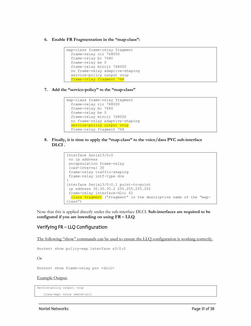
6. Enable FR Fragmentation in the “map-class”:
map-class frame-relay fragment frame-relay cir 768000 frame-relay bc 7680 frame-relay be 0 frame-relay mincir 768000 no frame-relay adaptive-shaping service-policy output voip frame-relay fragment 768
7. Add the “service-policy” to the “map-class”
map-class frame-relay fragment frame-relay cir 768000 frame-relay bc 7680 frame-relay be 0 frame-relay mincir 768000 no frame-relay adaptive-shaping service-policy output voip frame-relay fragment 768
8. Finally, it is time to apply the “map-class” to the voice/data PVC sub-interface
DLCI .
Interface Serial3/0:0 no ip address encapsulation frame-relay load-interval 30 frame-relay traffic-shaping frame-relay intf-type dce ! interface Serial3/0:0.1 point-to-point ip address 30.30.30.2 255.255.255.252 frame-relay interface-dlci 61 class fragment (“fragment” is the descriptive name of the “map-class”)
Note that this is applied directly under the sub-interface DLCI. Sub-interfaces are required to be configured if you are intending on using FR – LLQ.
Verifying FR – LLQ Configuration The following “show” commands can be used to ensure the LLQ configuration is working correctly. Router> show policy-map interface s3/0:0 Or Router> show frame-relay pvc <dlci> Example Output: Service-policy output: voip Class-map: voice (match-all)
Nortel Networks Page 31 of 38
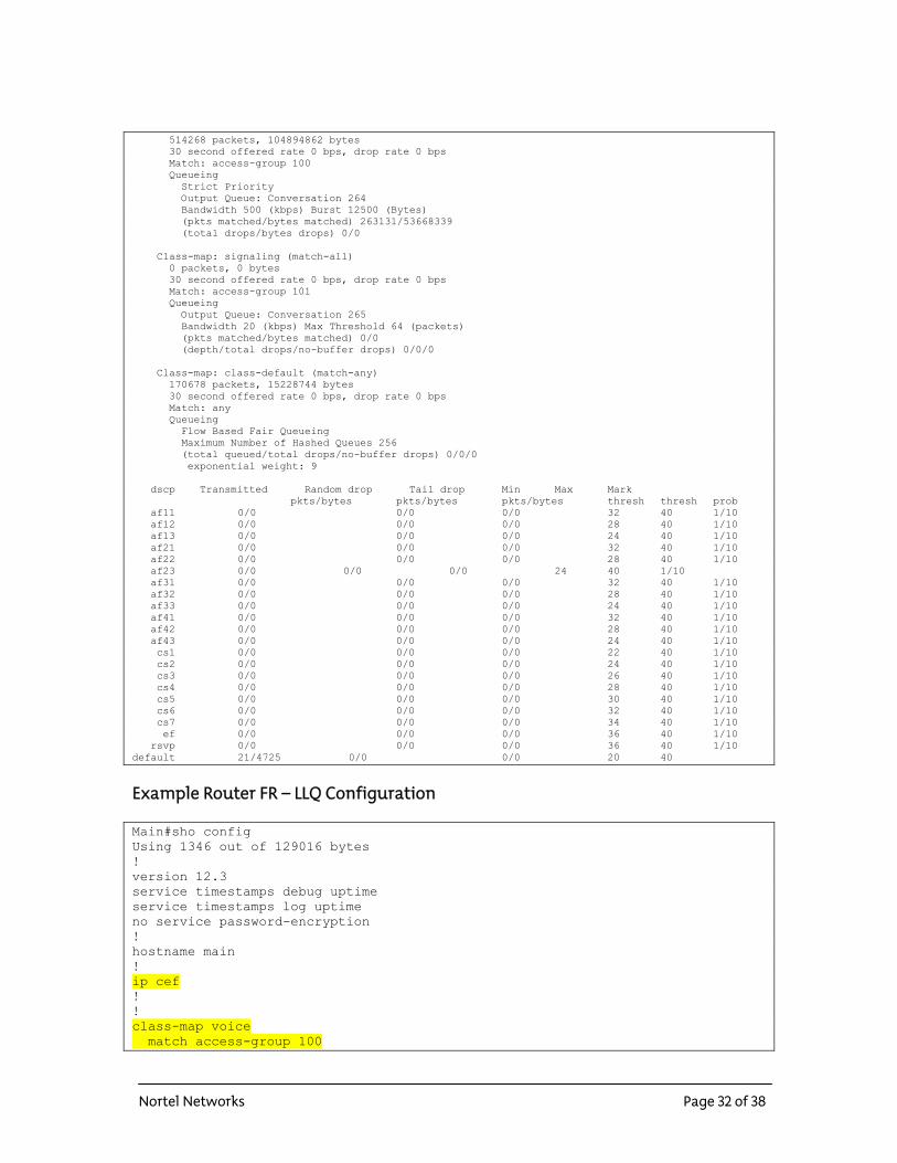
514268 packets, 104894862 bytes 30 second offered rate 0 bps, drop rate 0 bps Match: access-group 100 Queueing Strict Priority Output Queue: Conversation 264 Bandwidth 500 (kbps) Burst 12500 (Bytes) (pkts matched/bytes matched) 263131/53668339 (total drops/bytes drops) 0/0 Class-map: signaling (match-all) 0 packets, 0 bytes 30 second offered rate 0 bps, drop rate 0 bps Match: access-group 101 Queueing Output Queue: Conversation 265 Bandwidth 20 (kbps) Max Threshold 64 (packets) (pkts matched/bytes matched) 0/0 (depth/total drops/no-buffer drops) 0/0/0 Class-map: class-default (match-any) 170678 packets, 15228744 bytes 30 second offered rate 0 bps, drop rate 0 bps Match: any Queueing Flow Based Fair Queueing Maximum Number of Hashed Queues 256 (total queued/total drops/no-buffer drops) 0/0/0 exponential weight: 9 dscp Transmitted Random drop Tail drop Min Max Mark pkts/bytes pkts/bytes pkts/bytes thresh thresh prob af11 0/0 0/0 0/0 32 40 1/10 af12 0/0 0/0 0/0 28 40 1/10 af13 0/0 0/0 0/0 24 40 1/10 af21 0/0 0/0 0/0 32 40 1/10 af22 0/0 0/0 0/0 28 40 1/10 af23 0/0 0/0 0/0 24 40 1/10 af31 0/0 0/0 0/0 32 40 1/10 af32 0/0 0/0 0/0 28 40 1/10 af33 0/0 0/0 0/0 24 40 1/10 af41 0/0 0/0 0/0 32 40 1/10 af42 0/0 0/0 0/0 28 40 1/10 af43 0/0 0/0 0/0 24 40 1/10 cs1 0/0 0/0 0/0 22 40 1/10 cs2 0/0 0/0 0/0 24 40 1/10 cs3 0/0 0/0 0/0 26 40 1/10 cs4 0/0 0/0 0/0 28 40 1/10 cs5 0/0 0/0 0/0 30 40 1/10 cs6 0/0 0/0 0/0 32 40 1/10 cs7 0/0 0/0 0/0 34 40 1/10 ef 0/0 0/0 0/0 36 40 1/10 rsvp 0/0 0/0 0/0 36 40 1/10 default 21/4725 0/0 0/0 20 40
Example Router FR – LLQ Configuration Main#sho config Using 1346 out of 129016 bytes ! version 12.3 service timestamps debug uptime service timestamps log uptime no service password-encryption ! hostname main ! ip cef ! ! class-map voice match access-group 100
Nortel Networks Page 32 of 38
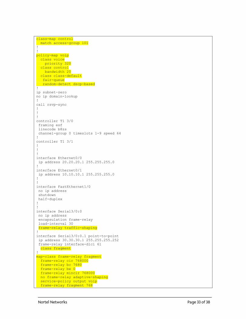
class-map control match access-group 101 ! ! policy-map voip class voice priority 320 class control bandwidth 20 class class-default fair-queue random-detect dscp-based ! ip subnet-zero no ip domain-lookup ! call rsvp-sync ! ! ! controller T1 3/0 framing esf linecode b8zs channel-group 0 timeslots 1-9 speed 64 ! controller T1 3/1 ! ! ! interface Ethernet0/0 ip address 20.20.20.1 255.255.255.0 ! interface Ethernet0/1 ip address 10.10.10.1 255.255.255.0 ! ! interface FastEthernet1/0 no ip address shutdown half-duplex ! ! interface Serial3/0:0 no ip address encapsulation frame-relay load-interval 30 frame-relay traffic-shaping ! interface Serial3/0:0.1 point-to-point ip address 30.30.30.1 255.255.255.252 frame-relay interface-dlci 61 class fragment ! map-class frame-relay fragment frame-relay cir 768000 frame-relay bc 7680 frame-relay be 0 frame-relay mincir 768000 no frame-relay adaptive-shaping service-policy output voip frame-relay fragment 768
Nortel Networks Page 33 of 38
ip classless ip route 47.0.0.0 255.0.0.0 10.10.10.4 ip route 47.100.251.0 255.255.255.0 30.30.30.1 no ip http server ! access-list 100 permit ip any any dscp 46 access-list 101 permit ip any any dscp 40 ! dial-peer cor custom ! ! ! ! line con 0 transport input none line aux 0 line vty 0 4 password telnet login
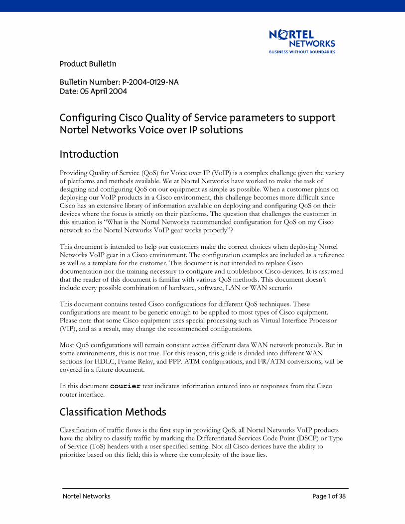
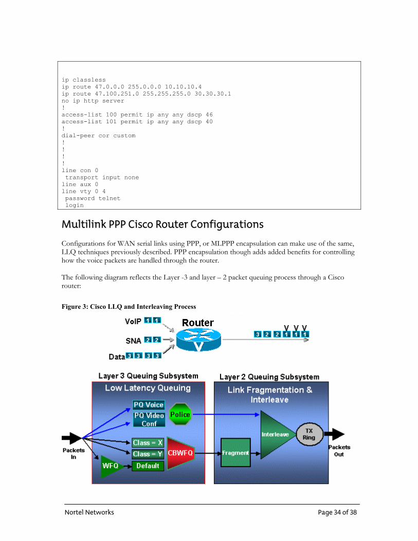
Multilink PPP Cisco Router Configurations Configurations for WAN serial links using PPP, or MLPPP encapsulation can make use of the same, LLQ techniques previously described. PPP encapsulation though adds added benefits for controlling how the voice packets are handled through the router. The following diagram reflects the Layer -3 and layer – 2 packet queuing process through a Cisco router:
Figure 3: Cisco LLQ and Interleaving Process
Nortel Networks Page 34 of 38
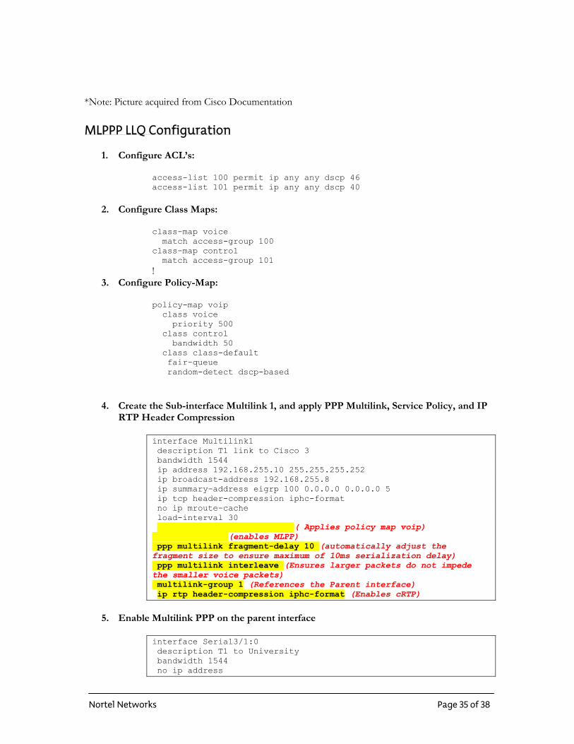
*Note: Picture acquired from Cisco Documentation MLPPP LLQ Configuration
1. Configure ACL’s:
access-list 100 permit ip any any dscp 46 access-list 101 permit ip any any dscp 40
2. Configure Class Maps:
class-map voice match access-group 100 class-map control match access-group 101 !
3. Configure Policy-Map:
policy-map voip class voice priority 500 class control bandwidth 50 class class-default fair-queue random-detect dscp-based
4. Create the Sub-interface Multilink 1, and apply PPP Multilink, Service Policy, and IP
RTP Header Compression
interface Multilink1 description T1 link to Cisco 3 bandwidth 1544 ip address 192.168.255.10 255.255.255.252 ip broadcast-address 192.168.255.8 ip summary-address eigrp 100 0.0.0.0 0.0.0.0 5 ip tcp header-compression iphc-format no ip mroute-cache load-interval 30 service-policy output voip ( Applies policy map voip)
ppp multilink (enables MLPP) ppp multilink fragment-delay 10 (automatically adjust the fragment size to ensure maximum of 10ms serialization delay) ppp multilink interleave (Ensures larger packets do not impede the smaller voice packets) multilink-group 1 (References the Parent interface) ip rtp header-compression iphc-format (Enables cRTP)
5. Enable Multilink PPP on the parent interface
interface Serial3/1:0 description T1 to University bandwidth 1544 no ip address
Nortel Networks Page 35 of 38
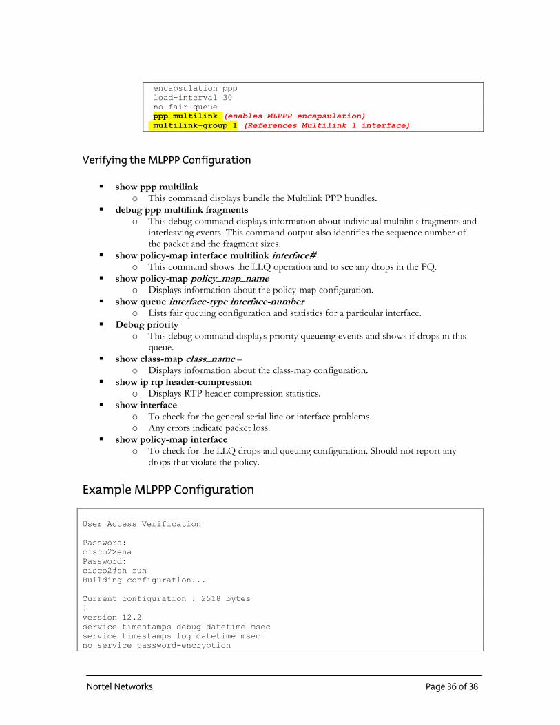
encapsulation ppp load-interval 30 no fair-queue ppp multilink (enables MLPPP encapsulation) multilink-group 1 (References Multilink 1 interface)
Verifying the MLPPP Configuration
show ppp multilink o This command displays bundle the Multilink PPP bundles.
debug ppp multilink fragments o This debug command displays information about individual multilink fragments and
interleaving events. This command output also identifies the sequence number of the packet and the fragment sizes.
show policy-map interface multilink interface# o This command shows the LLQ operation and to see any drops in the PQ.
show policy-map pol cy_map_name io Displays information about the policy-map configuration.
show queue interface-type interface-number o Lists fair queuing configuration and statistics for a particular interface.
Debug priority o This debug command displays priority queueing events and shows if drops in this
queue. show class-map class_name –
o Displays information about the class-map configuration. show ip rtp header-compression
o Displays RTP header compression statistics. show interface
o To check for the general serial line or interface problems. o Any errors indicate packet loss.
show policy-map interface o To check for the LLQ drops and queuing configuration. Should not report any
drops that violate the policy. Example MLPPP Configuration User Access Verification Password: cisco2>ena Password: cisco2#sh run Building configuration... Current configuration : 2518 bytes ! version 12.2 service timestamps debug datetime msec service timestamps log datetime msec no service password-encryption
Nortel Networks Page 36 of 38
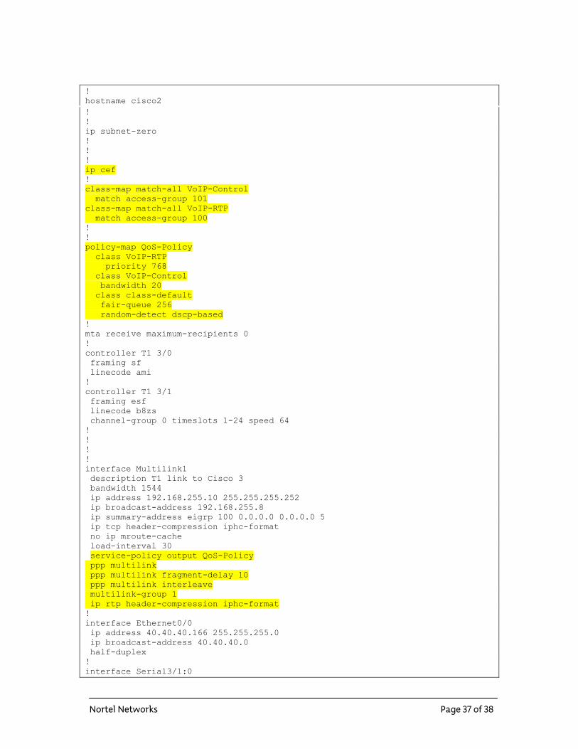
! hostname cisco2 ! ! ip subnet-zero ! ! ! ip cef ! class-map match-all VoIP-Control match access-group 101 class-map match-all VoIP-RTP match access-group 100 ! ! policy-map QoS-Policy class VoIP-RTP priority 768 class VoIP-Control bandwidth 20 class class-default fair-queue 256 random-detect dscp-based ! mta receive maximum-recipients 0 ! controller T1 3/0 framing sf linecode ami ! controller T1 3/1 framing esf linecode b8zs channel-group 0 timeslots 1-24 speed 64 ! ! ! ! interface Multilink1 description T1 link to Cisco 3 bandwidth 1544 ip address 192.168.255.10 255.255.255.252 ip broadcast-address 192.168.255.8 ip summary-address eigrp 100 0.0.0.0 0.0.0.0 5 ip tcp header-compression iphc-format no ip mroute-cache load-interval 30 service-policy output QoS-Policy ppp multilink ppp multilink fragment-delay 10 ppp multilink interleave multilink-group 1 ip rtp header-compression iphc-format ! interface Ethernet0/0 ip address 40.40.40.166 255.255.255.0 ip broadcast-address 40.40.40.0 half-duplex ! interface Serial3/1:0
Nortel Networks Page 37 of 38
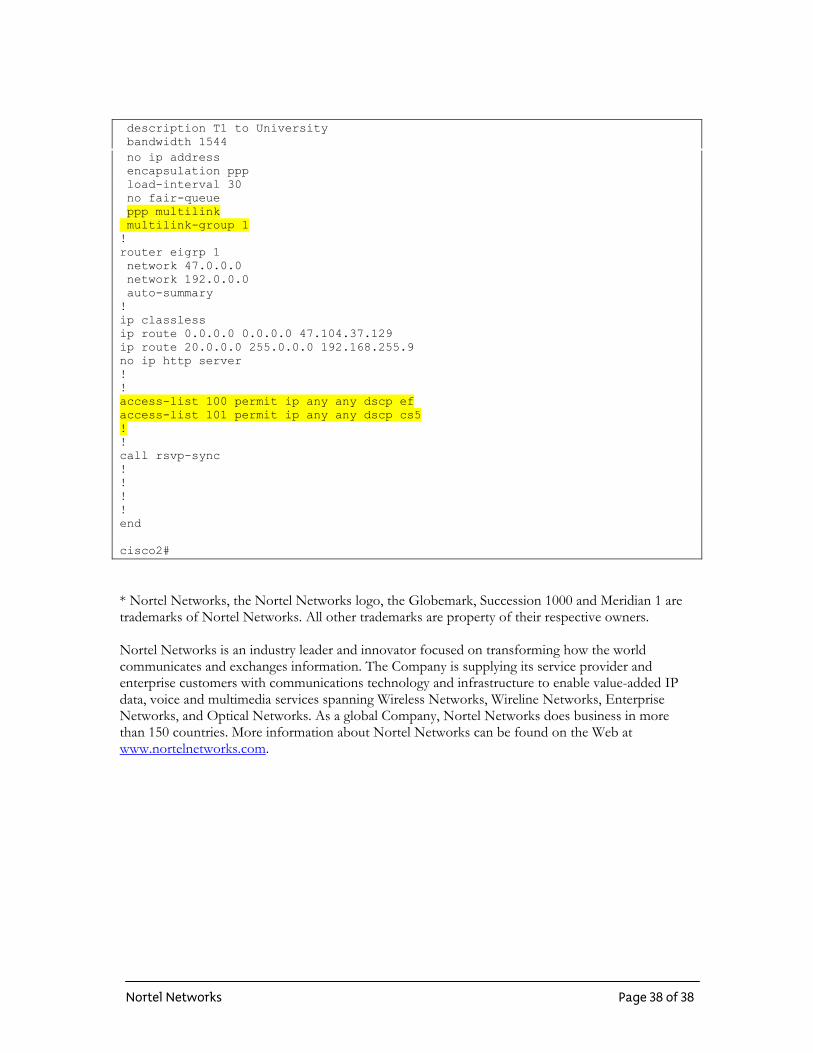
description T1 to University bandwidth 1544 no ip address encapsulation ppp load-interval 30 no fair-queue ppp multilink multilink-group 1 ! router eigrp 1 network 47.0.0.0 network 192.0.0.0 auto-summary ! ip classless ip route 0.0.0.0 0.0.0.0 47.104.37.129 ip route 20.0.0.0 255.0.0.0 192.168.255.9 no ip http server ! ! access-list 100 permit ip any any dscp ef access-list 101 permit ip any any dscp cs5 ! ! call rsvp-sync ! ! ! ! end cisco2#
* Nortel Networks, the Nortel Networks logo, the Globemark, Succession 1000 and Meridian 1 are trademarks of Nortel Networks. All other trademarks are property of their respective owners. Nortel Networks is an industry leader and innovator focused on transforming how the world communicates and exchanges information. The Company is supplying its service provider and enterprise customers with communications technology and infrastructure to enable value-added IP data, voice and multimedia services spanning Wireless Networks, Wireline Networks, Enterprise Networks, and Optical Networks. As a global Company, Nortel Networks does business in more than 150 countries. More information about Nortel Networks can be found on the Web at www.nortelnetworks.com.
Nortel Networks Page 38 of 38