Embed Size (px)
Citation preview
Cisco ASR 9000 SeriesOL-26103-02
C H A P T E R 3
Configuring General Router FeaturesThis chapter describes how to communicate with the router using the command-line interface (CLI), and it also shows basic Cisco IOS XR software configuration management.
Contents• Connecting and Communicating with the Router, page 3-31
• Logging In to a Router, page 3-37
• CLI Prompt, page 3-38
• User Access Privileges, page 3-39
• Navigating the Cisco IOS XR Command Modes, page 3-43
• Managing Configuration Sessions, page 3-49
• Configuring the RSP Hostname, page 3-64
• Configuring the Management Ethernet Interface, page 3-64
• Manually Setting the Router Clock, page 3-69
• Where to Go Next, page 3-71
Connecting and Communicating with the RouterTo use a router running Cisco IOS XR Software, first connect to it using a terminal or a PC. Before you connect to the router, determine which entity to manage. You can manage router hardware or named RSPs.
Connections are made either through a direct physical connection to the console port or through management interfaces.
Figure 3-1 shows the RSP connections for a Cisco ASR 9000 Series Router.
The first time a router starts, use a direct connection to the Console port to type the configuration information. When the router is directly connected to the Console port, enter CLI commands at a terminal or at a computer running terminal emulation software. This direct Console port connection is useful for entering initial configurations and performing some debugging tasks.
3-31 Aggregation Services Router Getting Started Guide
Chapter 3 Configuring General Router Features Connecting and Communicating with the Router
This chapter describes some of the tasks to perform during your initial configuration. One of those tasks is the configuration of the Management Ethernet interface, which is described in the “Configuring the Management Ethernet Interface” section on page 3-64. After the Management Ethernet interface is configured, most router management and configuration sessions take place over an Ethernet network connected to the Management Ethernet interface. SNMP agents also use the network connection.
You can use the modem connection for remote communications with the router. If the Management Ethernet interface fails, the modem connection serves as the alternate remote communications path.
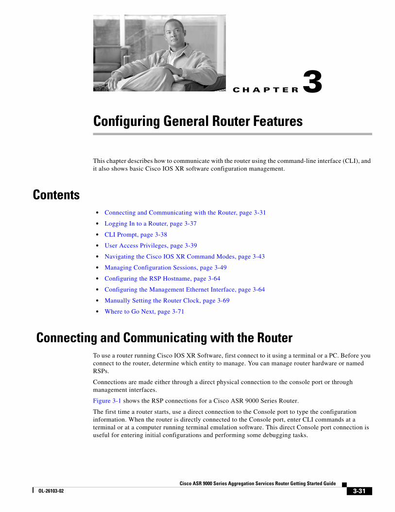
Figure 3-1 Communication Ports on the RSP Card for a Cisco ASR 9000 Series Router
2430
91
MG
T L
AN
0M
GT
LA
N 1
CO
NS
OL
EA
UX
SY
NC
0S
YN
C 1
AL
AR
M O
UT
KE
EP
CL
OS
ED
CO
MPA
CT FLA
SH
AC
CE
SS
ACO
ACO
LAMPTEST
SYNC
HDD
CF
FAIL
CRIT
MAJ
MIN
A9K-RSP-4G
LINK
AC
TLIN
K A
CT
BITS
J.211 B
ITS J.211
4
5
8
1
2
3
7
6
3-32Cisco ASR 9000 Series Aggregation Services Router Getting Started Guide
OL-26103-02
Chapter 3 Configuring General Router Features Connecting and Communicating with the Router
The following sections describe three ways to connect to the router:
• Establishing a Connection Through the Console Port, page 3-33
• Establishing a Connection Through a Terminal Server, page 3-35
• Establishing a Connection Through the Management Ethernet Interface, page 3-37
Establishing a Connection Through the Console PortTo connect to the router through the console port, perform the following procedure.
SUMMARY STEPS
1. Identify the active RSP.
2. Connect a terminal to the Console port of the active RSP.
3. Start the terminal emulation program.
4. Press Enter.
5. Log in to the router.
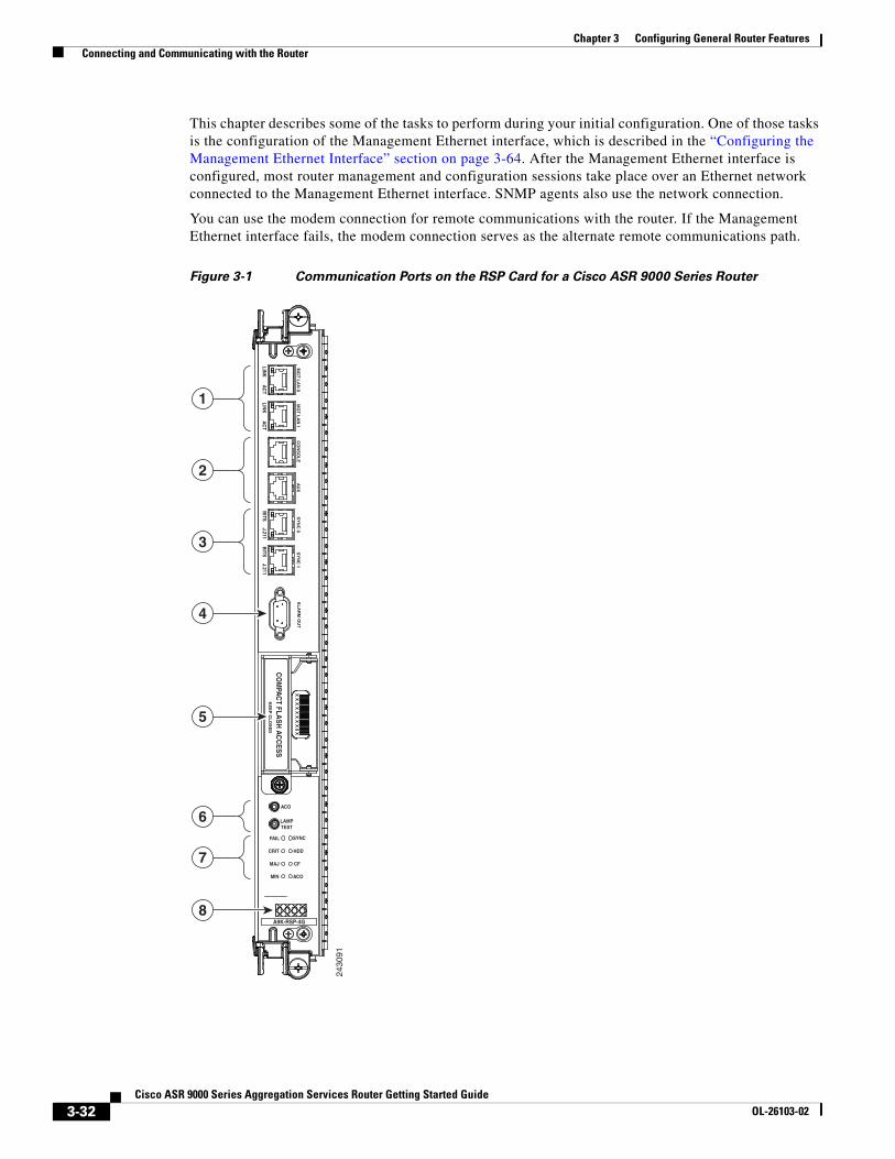
1 Management LAN Ports 5 Compact Flash type I/II
2 Console Port and Auxiliary Port 6 Alarm Cutoff (ACO) and Lamp Test push buttons
3 Sync (BITS and J.211) ports 7 Eight discrete LED indicators
4 Alarm Out DB9 Connector 8 LED Matrix display
3-33Cisco ASR 9000 Series Aggregation Services Router Getting Started Guide
OL-26103-02
Chapter 3 Configuring General Router Features Connecting and Communicating with the Router
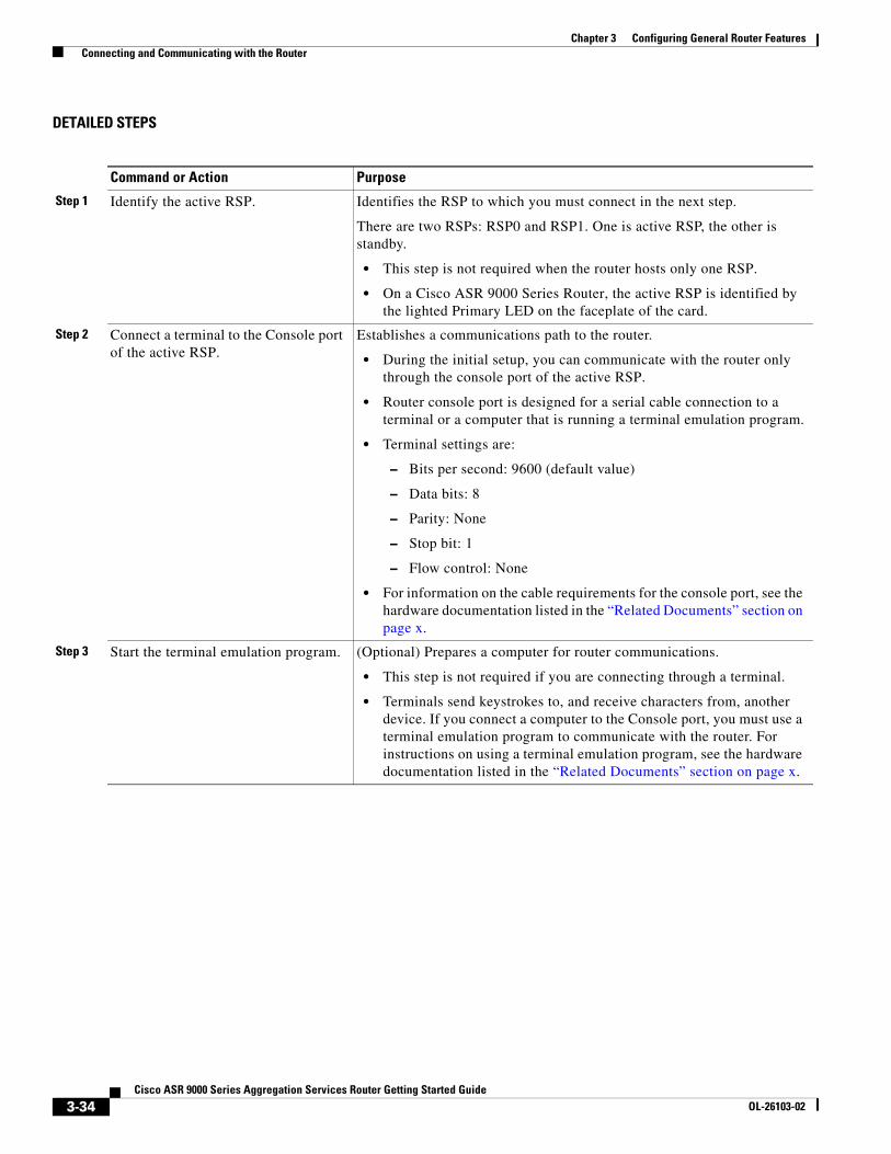
DETAILED STEPS
Command or Action Purpose
Step 1 Identify the active RSP. Identifies the RSP to which you must connect in the next step.
There are two RSPs: RSP0 and RSP1. One is active RSP, the other is standby.
• This step is not required when the router hosts only one RSP.
• On a Cisco ASR 9000 Series Router, the active RSP is identified by the lighted Primary LED on the faceplate of the card.
Step 2 Connect a terminal to the Console port of the active RSP.
Establishes a communications path to the router.
• During the initial setup, you can communicate with the router only through the console port of the active RSP.
• Router console port is designed for a serial cable connection to a terminal or a computer that is running a terminal emulation program.
• Terminal settings are:
– Bits per second: 9600 (default value)
– Data bits: 8
– Parity: None
– Stop bit: 1
– Flow control: None
• For information on the cable requirements for the console port, see the hardware documentation listed in the “Related Documents” section on page x.
Step 3 Start the terminal emulation program. (Optional) Prepares a computer for router communications.
• This step is not required if you are connecting through a terminal.
• Terminals send keystrokes to, and receive characters from, another device. If you connect a computer to the Console port, you must use a terminal emulation program to communicate with the router. For instructions on using a terminal emulation program, see the hardware documentation listed in the “Related Documents” section on page x.
3-34Cisco ASR 9000 Series Aggregation Services Router Getting Started Guide
OL-26103-02
Chapter 3 Configuring General Router Features Connecting and Communicating with the Router
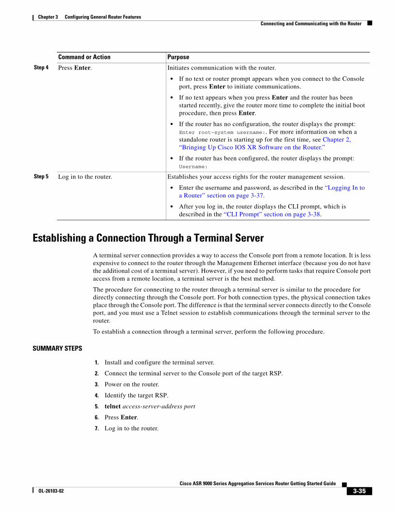
Establishing a Connection Through a Terminal ServerA terminal server connection provides a way to access the Console port from a remote location. It is less expensive to connect to the router through the Management Ethernet interface (because you do not have the additional cost of a terminal server). However, if you need to perform tasks that require Console port access from a remote location, a terminal server is the best method.
The procedure for connecting to the router through a terminal server is similar to the procedure for directly connecting through the Console port. For both connection types, the physical connection takes place through the Console port. The difference is that the terminal server connects directly to the Console port, and you must use a Telnet session to establish communications through the terminal server to the router.
To establish a connection through a terminal server, perform the following procedure.
SUMMARY STEPS
1. Install and configure the terminal server.
2. Connect the terminal server to the Console port of the target RSP.
3. Power on the router.
4. Identify the target RSP.
5. telnet access-server-address port
6. Press Enter.
7. Log in to the router.
Step 4 Press Enter. Initiates communication with the router.
• If no text or router prompt appears when you connect to the Console port, press Enter to initiate communications.
• If no text appears when you press Enter and the router has been started recently, give the router more time to complete the initial boot procedure, then press Enter.
• If the router has no configuration, the router displays the prompt: Enter root-system username:. For more information on when a standalone router is starting up for the first time, see Chapter 2, “Bringing Up Cisco IOS XR Software on the Router.”
• If the router has been configured, the router displays the prompt: Username:
Step 5 Log in to the router. Establishes your access rights for the router management session.
• Enter the username and password, as described in the “Logging In to a Router” section on page 3-37.
• After you log in, the router displays the CLI prompt, which is described in the “CLI Prompt” section on page 3-38.
Command or Action Purpose
3-35Cisco ASR 9000 Series Aggregation Services Router Getting Started Guide
OL-26103-02
Chapter 3 Configuring General Router Features Connecting and Communicating with the Router
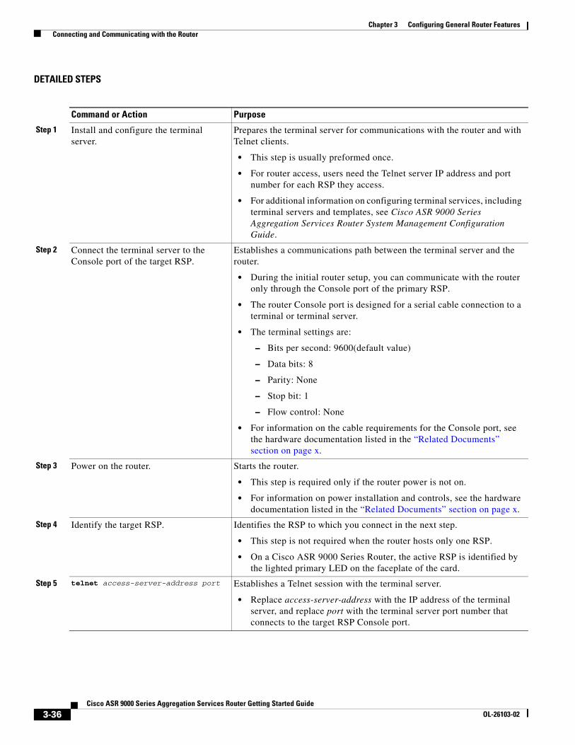
DETAILED STEPS
Command or Action Purpose
Step 1 Install and configure the terminal server.
Prepares the terminal server for communications with the router and with Telnet clients.
• This step is usually preformed once.
• For router access, users need the Telnet server IP address and port number for each RSP they access.
• For additional information on configuring terminal services, including terminal servers and templates, see Cisco ASR 9000 Series Aggregation Services Router System Management Configuration Guide.
Step 2 Connect the terminal server to the Console port of the target RSP.
Establishes a communications path between the terminal server and the router.
• During the initial router setup, you can communicate with the router only through the Console port of the primary RSP.
• The router Console port is designed for a serial cable connection to a terminal or terminal server.
• The terminal settings are:
– Bits per second: 9600(default value)
– Data bits: 8
– Parity: None
– Stop bit: 1
– Flow control: None
• For information on the cable requirements for the Console port, see the hardware documentation listed in the “Related Documents” section on page x.
Step 3 Power on the router. Starts the router.
• This step is required only if the router power is not on.
• For information on power installation and controls, see the hardware documentation listed in the “Related Documents” section on page x.
Step 4 Identify the target RSP. Identifies the RSP to which you connect in the next step.
• This step is not required when the router hosts only one RSP.
• On a Cisco ASR 9000 Series Router, the active RSP is identified by the lighted primary LED on the faceplate of the card.
Step 5 telnet access-server-address port Establishes a Telnet session with the terminal server.
• Replace access-server-address with the IP address of the terminal server, and replace port with the terminal server port number that connects to the target RSP Console port.
3-36Cisco ASR 9000 Series Aggregation Services Router Getting Started Guide
OL-26103-02
Chapter 3 Configuring General Router Features Logging In to a Router
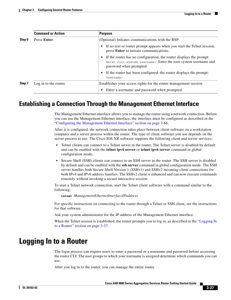
Establishing a Connection Through the Management Ethernet InterfaceThe Management Ethernet interface allows you to manage the router using a network connection. Before you can use the Management Ethernet interface, the interface must be configured as described in the “Configuring the Management Ethernet Interface” section on page 3-66.
After it is configured, the network connection takes place between client software on a workstation computer and a server process within the router. The type of client software you use depends on the server process to use. The Cisco IOS XR software supports the following client and server services:
• Telnet clients can connect to a Telnet server in the router. The Telnet server is disabled by default and can be enabled with the telnet ipv4 server or telnet ipv6 server command in global configuration mode.
• Secure Shell (SSH) clients can connect to an SSH server in the router. The SSH server is disabled by default and can be enabled with the ssh server command in global configuration mode. The SSH server handles both Secure Shell Version 1 (SSHv1) and SSHv2 incoming client connections for both IPv4 and IPv6 address families. The SSHv2 client is enhanced and can now execute commands remotely without invoking a secure interactive session.
To start a Telnet network connection, start the Telnet client software with a command similar to the following:
telnet ManagementEthernetInterfaceIPaddress
For specific instructions on connecting to the router through a Telnet or SSH client, see the instructions for that software.
Ask your system administrator for the IP address of the Management Ethernet interface.
When the Telnet session is established, the router prompts you to log in, as described in the “Logging In to a Router” section on page 3-37.
Logging In to a Router The login process can require users to enter a password or a username and password before accessing the router CLI. The user groups to which your username is assigned determine which commands you can use.
After you log in to the router, you can manage the entire router.
Step 6 Press Enter. (Optional) Initiates communications with the RSP.
• If no text or router prompt appears when you start the Telnet session, press Enter to initiate communications.
• If the router has no configuration, the router displays the prompt: Enter root-system username: Enter the root-system username and password when prompted.
• If the router has been configured, the router displays the prompt: Username:
Step 7 Log in to the router. Establishes your access rights for the router management session.
• Enter a username and password when prompted.
Command or Action Purpose
3-37Cisco ASR 9000 Series Aggregation Services Router Getting Started Guide
OL-26103-02
Chapter 3 Configuring General Router Features CLI Prompt
When you log in, the username and password may be validated by any of the following services:
• Usernames configured on the router (username command in global configuration mode)
• Root-system usernames that are configured
• Passwords configured for the router console and auxiliary ports (password or secret command in line configuration mode)
• RADIUS server
• TACACS+ server
The username and password validation method that your router uses is determined by the router configuration. For information on configuring username and password validation methods, see Cisco ASR 9000 Series Aggregation Services Router System Security Configuration Guide. For information on which username and password to use, see your system administrator.
To log in to the router, enter your username and password when prompted. For example:
User Access Verification
Username: iosxrPassword: passwordRP/0/RSP0/CPU0:router#
Note Passwords are case sensitive. To log in to the router using a root-system username , enter the username in the following format: username@admin. To support admin login, local database authentication must be enabled with the aaa authentication login remote local command. For more information, see Cisco ASR 9000 Series Aggregation Services Router System Security Configuration Guide.
After you log in, the router displays the CLI prompt, which is described in the “CLI Prompt” section on page 3-38. The command set that you can use is determined by the privileges assigned to your username. For information on how privileges are assigned to usernames, see Cisco ASR 9000 Series Aggregation Services Router System Security Configuration Guide.
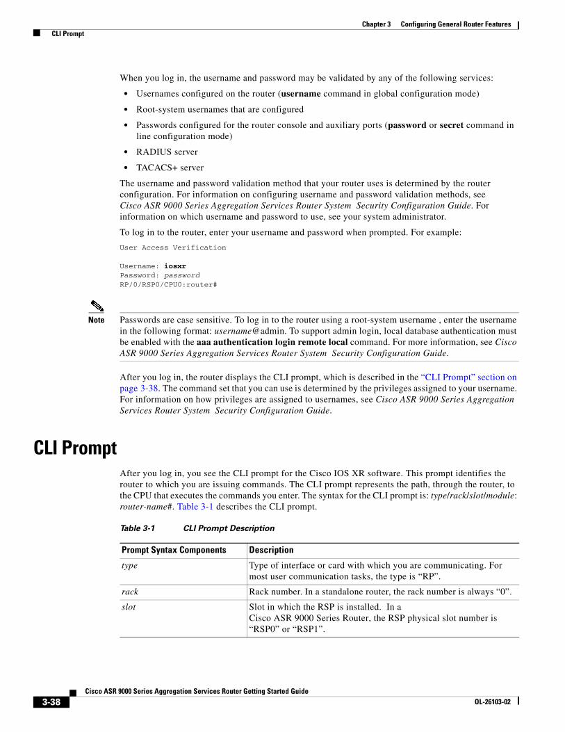
CLI PromptAfter you log in, you see the CLI prompt for the Cisco IOS XR software. This prompt identifies the router to which you are issuing commands. The CLI prompt represents the path, through the router, to the CPU that executes the commands you enter. The syntax for the CLI prompt is: type/rack/slot/module: router-name#. Table 3-1 describes the CLI prompt.
Table 3-1 CLI Prompt Description
Prompt Syntax Components Description
type Type of interface or card with which you are communicating. For most user communication tasks, the type is “RP”.
rack Rack number. In a standalone router, the rack number is always “0”.
slot Slot in which the RSP is installed. In a Cisco ASR 9000 Series Router, the RSP physical slot number is “RSP0” or “RSP1”.
3-38Cisco ASR 9000 Series Aggregation Services Router Getting Started Guide
OL-26103-02
Chapter 3 Configuring General Router Features User Access Privileges
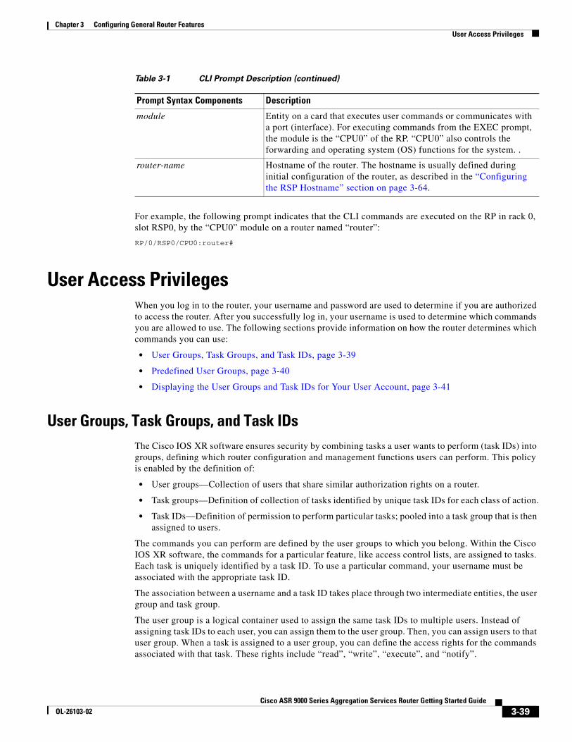
For example, the following prompt indicates that the CLI commands are executed on the RP in rack 0, slot RSP0, by the “CPU0” module on a router named “router”:
RP/0/RSP0/CPU0:router#
User Access PrivilegesWhen you log in to the router, your username and password are used to determine if you are authorized to access the router. After you successfully log in, your username is used to determine which commands you are allowed to use. The following sections provide information on how the router determines which commands you can use:
• User Groups, Task Groups, and Task IDs, page 3-39
• Predefined User Groups, page 3-40
• Displaying the User Groups and Task IDs for Your User Account, page 3-41
User Groups, Task Groups, and Task IDsThe Cisco IOS XR software ensures security by combining tasks a user wants to perform (task IDs) into groups, defining which router configuration and management functions users can perform. This policy is enabled by the definition of:
• User groups—Collection of users that share similar authorization rights on a router.
• Task groups—Definition of collection of tasks identified by unique task IDs for each class of action.
• Task IDs—Definition of permission to perform particular tasks; pooled into a task group that is then assigned to users.
The commands you can perform are defined by the user groups to which you belong. Within the Cisco IOS XR software, the commands for a particular feature, like access control lists, are assigned to tasks. Each task is uniquely identified by a task ID. To use a particular command, your username must be associated with the appropriate task ID.
The association between a username and a task ID takes place through two intermediate entities, the user group and task group.
The user group is a logical container used to assign the same task IDs to multiple users. Instead of assigning task IDs to each user, you can assign them to the user group. Then, you can assign users to that user group. When a task is assigned to a user group, you can define the access rights for the commands associated with that task. These rights include “read”, “write”, “execute”, and “notify”.
module Entity on a card that executes user commands or communicates with a port (interface). For executing commands from the EXEC prompt, the module is the “CPU0” of the RP. “CPU0” also controls the forwarding and operating system (OS) functions for the system. .
router-name Hostname of the router. The hostname is usually defined during initial configuration of the router, as described in the “Configuring the RSP Hostname” section on page 3-64.
Table 3-1 CLI Prompt Description (continued)
Prompt Syntax Components Description
3-39Cisco ASR 9000 Series Aggregation Services Router Getting Started Guide
OL-26103-02
Chapter 3 Configuring General Router Features User Access Privileges
The task group is also a logical container, but it is used to group tasks. Instead of assigning task IDs to each user group, you assign them to a task group. This allows you to quickly enable access to a specific set of tasks by assigning a task group to a user group.
To summarize the associations, usernames are assigned to user groups, which are then assigned to task groups. Users can be assigned to multiple user groups, and each user group can be assigned to one or more task groups. The commands that a user can execute are all those commands assigned to the tasks within the task groups that are associated with the user groups to which the user belongs.
Users are not assigned to groups by default and must be explicitly assigned by an administrator.
Note Only the root-system users, root-lr users, or users associated with the WRITE:AAA task ID can configure task groups.
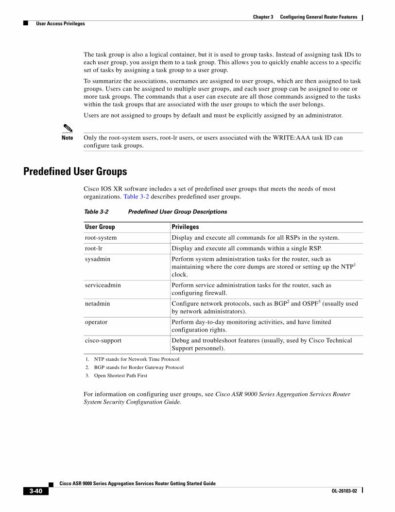
Predefined User GroupsCisco IOS XR software includes a set of predefined user groups that meets the needs of most organizations. Table 3-2 describes predefined user groups.
For information on configuring user groups, see Cisco ASR 9000 Series Aggregation Services Router System Security Configuration Guide.
Table 3-2 Predefined User Group Descriptions
User Group Privileges
root-system Display and execute all commands for all RSPs in the system.
root-lr Display and execute all commands within a single RSP.
sysadmin Perform system administration tasks for the router, such as maintaining where the core dumps are stored or setting up the NTP1 clock.
1. NTP stands for Network Time Protocol
serviceadmin Perform service administration tasks for the router, such as configuring firewall.
netadmin Configure network protocols, such as BGP2 and OSPF3 (usually used by network administrators).
2. BGP stands for Border Gateway Protocol
3. Open Shortest Path First
operator Perform day-to-day monitoring activities, and have limited configuration rights.
cisco-support Debug and troubleshoot features (usually, used by Cisco Technical Support personnel).
3-40Cisco ASR 9000 Series Aggregation Services Router Getting Started Guide
OL-26103-02
Chapter 3 Configuring General Router Features User Access Privileges
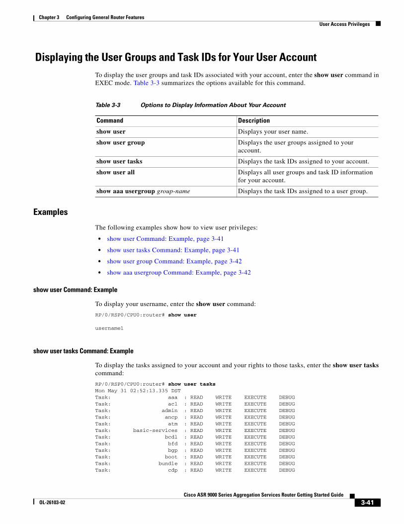
Displaying the User Groups and Task IDs for Your User Account To display the user groups and task IDs associated with your account, enter the show user command in EXEC mode. Table 3-3 summarizes the options available for this command.
Examples
The following examples show how to view user privileges:
• show user Command: Example, page 3-41
• show user tasks Command: Example, page 3-41
• show user group Command: Example, page 3-42
• show aaa usergroup Command: Example, page 3-42
show user Command: Example
To display your username, enter the show user command:
RP/0/RSP0/CPU0:router# show user
username1
show user tasks Command: Example
To display the tasks assigned to your account and your rights to those tasks, enter the show user tasks command:
RP/0/RSP0/CPU0:router# show user tasksMon May 31 02:52:13.335 DSTTask: aaa : READ WRITE EXECUTE DEBUGTask: acl : READ WRITE EXECUTE DEBUGTask: admin : READ WRITE EXECUTE DEBUGTask: ancp : READ WRITE EXECUTE DEBUGTask: atm : READ WRITE EXECUTE DEBUGTask: basic-services : READ WRITE EXECUTE DEBUGTask: bcdl : READ WRITE EXECUTE DEBUGTask: bfd : READ WRITE EXECUTE DEBUGTask: bgp : READ WRITE EXECUTE DEBUGTask: boot : READ WRITE EXECUTE DEBUGTask: bundle : READ WRITE EXECUTE DEBUGTask: cdp : READ WRITE EXECUTE DEBUG
Table 3-3 Options to Display Information About Your Account
Command Description
show user Displays your user name.
show user group Displays the user groups assigned to your account.
show user tasks Displays the task IDs assigned to your account.
show user all Displays all user groups and task ID information for your account.
show aaa usergroup group-name Displays the task IDs assigned to a user group.
3-41Cisco ASR 9000 Series Aggregation Services Router Getting Started Guide
OL-26103-02
Chapter 3 Configuring General Router Features User Access Privileges
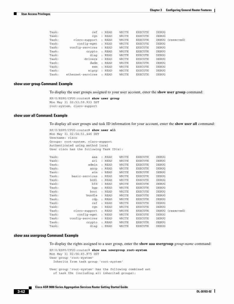
Task: cef : READ WRITE EXECUTE DEBUGTask: cgn : READ WRITE EXECUTE DEBUGTask: cisco-support : READ WRITE EXECUTE DEBUG (reserved)Task: config-mgmt : READ WRITE EXECUTE DEBUGTask: config-services : READ WRITE EXECUTE DEBUGTask: crypto : READ WRITE EXECUTE DEBUGTask: diag : READ WRITE EXECUTE DEBUGTask: drivers : READ WRITE EXECUTE DEBUGTask: dwdm : READ WRITE EXECUTE DEBUGTask: eem : READ WRITE EXECUTE DEBUGTask: eigrp : READ WRITE EXECUTE DEBUGTask: ethernet-services : READ WRITE EXECUTE DEBUG
show user group Command: Example
To display the user groups assigned to your user account, enter the show user group command:
RP/0/RSP0/CPU0:router# show user groupMon May 31 02:53:59.933 DSTroot-system, cisco-support
show user all Command: Example
To display all user groups and task ID information for your account, enter the show user all command:
RP/0/RSP0/CPU0:router# show user allMon May 31 02:54:51.446 DSTUsername: ciscoGroups: root-system, cisco-supportAuthenticated using method localUser cisco has the following Task ID(s):
Task: aaa : READ WRITE EXECUTE DEBUGTask: acl : READ WRITE EXECUTE DEBUGTask: admin : READ WRITE EXECUTE DEBUGTask: ancp : READ WRITE EXECUTE DEBUGTask: atm : READ WRITE EXECUTE DEBUGTask: basic-services : READ WRITE EXECUTE DEBUGTask: bcdl : READ WRITE EXECUTE DEBUGTask: bfd : READ WRITE EXECUTE DEBUGTask: bgp : READ WRITE EXECUTE DEBUGTask: boot : READ WRITE EXECUTE DEBUGTask: bundle : READ WRITE EXECUTE DEBUGTask: cdp : READ WRITE EXECUTE DEBUGTask: cef : READ WRITE EXECUTE DEBUGTask: cgn : READ WRITE EXECUTE DEBUGTask: cisco-support : READ WRITE EXECUTE DEBUG (reserved)Task: config-mgmt : READ WRITE EXECUTE DEBUGTask: config-services : READ WRITE EXECUTE DEBUGTask: crypto : READ WRITE EXECUTE DEBUGTask: diag : READ WRITE EXECUTE DEBUG
show aaa usergroup Command: Example
To display the rights assigned to a user group, enter the show aaa usergroup group-name command:
RP/0/RSP0/CPU0:router# show aaa usergroup root-systemMon May 31 02:56:45.975 DSTUser group 'root-system' Inherits from task group 'root-system'
User group 'root-system' has the following combined set of task IDs (including all inherited groups):
3-42Cisco ASR 9000 Series Aggregation Services Router Getting Started Guide
OL-26103-02
Chapter 3 Configuring General Router Features Navigating the Cisco IOS XR Command Modes
Task: aaa : READ WRITE EXECUTE DEBUGTask: acl : READ WRITE EXECUTE DEBUGTask: admin : READ WRITE EXECUTE DEBUGTask: ancp : READ WRITE EXECUTE DEBUGTask: atm : READ WRITE EXECUTE DEBUGTask: basic-services : READ WRITE EXECUTE DEBUGTask: bcdl : READ WRITE EXECUTE DEBUGTask: bfd : READ WRITE EXECUTE DEBUGTask: bgp : READ WRITE EXECUTE DEBUGTask: boot : READ WRITE EXECUTE DEBUGTask: bundle : READ WRITE EXECUTE DEBUGTask: cdp : READ WRITE EXECUTE DEBUGTask: cef : READ WRITE EXECUTE DEBUGTask: cgn : READ WRITE EXECUTE DEBUGTask: config-mgmt : READ WRITE EXECUTE DEBUGTask: config-services : READ WRITE EXECUTE DEBUGTask: crypto : READ WRITE EXECUTE DEBUGTask: diag : READ WRITE EXECUTE DEBUG
Navigating the Cisco IOS XR Command Modes The Cisco IOS XR Software has different command modes. Each mode provides access to a subset of commands used to configure, monitor, and manage the router. Access to a mode is determined by your user group assignments. The following sections describe the navigation of the command modes:
• Identifying the Command Mode in the CLI Prompt, page 3-44
• Summary of Common Command Modes, page 3-45
• Entering EXEC Commands from a Configuration Mode, page 3-47
• Command Mode Navigation Example, page 3-48
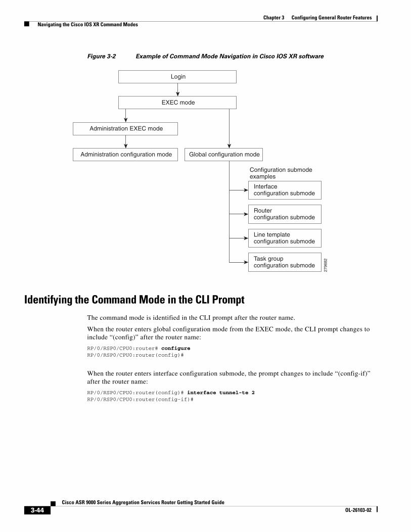
Figure 3-2 illustrates the basic command mode navigation for the CLI. Only a small sample of the possible configuration modes is shown.
3-43Cisco ASR 9000 Series Aggregation Services Router Getting Started Guide
OL-26103-02
Chapter 3 Configuring General Router Features Navigating the Cisco IOS XR Command Modes
Figure 3-2 Example of Command Mode Navigation in Cisco IOS XR software
Identifying the Command Mode in the CLI PromptThe command mode is identified in the CLI prompt after the router name.
When the router enters global configuration mode from the EXEC mode, the CLI prompt changes to include “(config)” after the router name:
RP/0/RSP0/CPU0:router# configureRP/0/RSP0/CPU0:router(config)#
When the router enters interface configuration submode, the prompt changes to include “(config-if)” after the router name:
RP/0/RSP0/CPU0:router(config)# interface tunnel-te 2 RP/0/RSP0/CPU0:router(config-if)#
2796
82
EXEC mode
Login
Interfaceconfiguration submode
Configuration submodeexamples
Routerconfiguration submode
Line templateconfiguration submode
Task groupconfiguration submode
Global configuration modeAdministration configuration mode
Administration EXEC mode
3-44Cisco ASR 9000 Series Aggregation Services Router Getting Started Guide
OL-26103-02
Chapter 3 Configuring General Router Features Navigating the Cisco IOS XR Command Modes
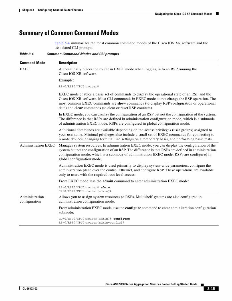
Summary of Common Command ModesTable 3-4 summarizes the most common command modes of the Cisco IOS XR software and the associated CLI prompts.
Table 3-4 Common Command Modes and CLI prompts
Command Mode Description
EXEC Automatically places the router in EXEC mode when logging in to an RSP running the Cisco IOS XR software.
Example:
RP/0/RSP0/CPU0:router#
EXEC mode enables a basic set of commands to display the operational state of an RSP and the Cisco IOS XR software. Most CLI commands in EXEC mode do not change the RSP operation. The most common EXEC commands are show commands (to display RSP configuration or operational data) and clear commands (to clear or reset RSP counters).
In EXEC mode, you can display the configuration of an RSP but not the configuration of the system. The difference is that RSPs are defined in administration configuration mode, which is a submode of administration EXEC mode. RSPs are configured in global configuration mode.
Additional commands are available depending on the access privileges (user groups) assigned to your username. Minimal privileges also include a small set of EXEC commands for connecting to remote devices, changing terminal line settings on a temporary basis, and performing basic tests.
Administration EXEC Manages system resources. In administration EXEC mode, you can display the configuration of the system but not the configuration of an RSP. The difference is that RSPs are defined in administration configuration mode, which is a submode of administration EXEC mode. RSPs are configured in global configuration mode.
Administration EXEC mode is used primarily to display system-wide parameters, configure the administration plane over the control Ethernet, and configure RSP. These operations are available only to users with the required root level access.
From EXEC mode, use the admin command to enter administration EXEC mode:
RP/0/RSP0/CPU0:router# adminRP/0/RSP0/CPU0:router(admin)#
Administration configuration
Allows you to assign system resources to RSPs. Multishelf systems are also configured in administration configuration mode.
From administration EXEC mode, use the configure command to enter administration configuration submode:
RP/0/RSP0/CPU0:router(admin)# configureRP/0/RSP0/CPU0:router(admin-config)#
3-45Cisco ASR 9000 Series Aggregation Services Router Getting Started Guide
OL-26103-02
Chapter 3 Configuring General Router Features Navigating the Cisco IOS XR Command Modes
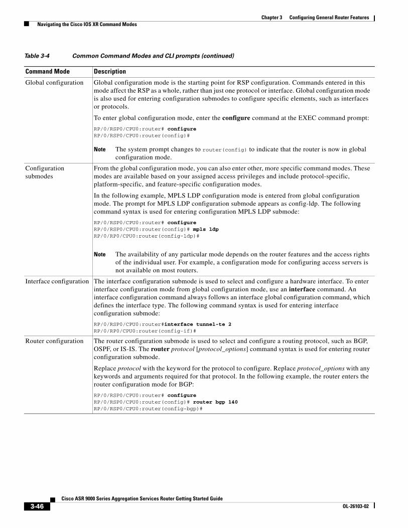
Global configuration Global configuration mode is the starting point for RSP configuration. Commands entered in this mode affect the RSP as a whole, rather than just one protocol or interface. Global configuration mode is also used for entering configuration submodes to configure specific elements, such as interfaces or protocols.
To enter global configuration mode, enter the configure command at the EXEC command prompt:
RP/0/RSP0/CPU0:router# configureRP/0/RSP0/CPU0:router(config)#
Note The system prompt changes to router(config) to indicate that the router is now in global configuration mode.
Configuration submodes
From the global configuration mode, you can also enter other, more specific command modes. These modes are available based on your assigned access privileges and include protocol-specific, platform-specific, and feature-specific configuration modes.
In the following example, MPLS LDP configuration mode is entered from global configuration mode. The prompt for MPLS LDP configuration submode appears as config-ldp. The following command syntax is used for entering configuration MPLS LDP submode:
RP/0/RSP0/CPU0:router# configureRP/0/RSP0/CPU0:router(config)# mpls ldpRP/0/RP0/CPU0:router(config-ldp)#
Note The availability of any particular mode depends on the router features and the access rights of the individual user. For example, a configuration mode for configuring access servers is not available on most routers.
Interface configuration The interface configuration submode is used to select and configure a hardware interface. To enter interface configuration mode from global configuration mode, use an interface command. An interface configuration command always follows an interface global configuration command, which defines the interface type. The following command syntax is used for entering interface configuration submode:
RP/0/RSP0/CPU0:router#interface tunnel-te 2RP/0/RP0/CPU0:router(config-if)#
Router configuration The router configuration submode is used to select and configure a routing protocol, such as BGP, OSPF, or IS-IS. The router protocol [protocol_options] command syntax is used for entering router configuration submode.
Replace protocol with the keyword for the protocol to configure. Replace protocol_options with any keywords and arguments required for that protocol. In the following example, the router enters the router configuration mode for BGP:
RP/0/RSP0/CPU0:router# configureRP/0/RSP0/CPU0:router(config)# router bgp 140RP/0/RSP0/CPU0:router(config-bgp)#
Table 3-4 Common Command Modes and CLI prompts (continued)
Command Mode Description
3-46Cisco ASR 9000 Series Aggregation Services Router Getting Started Guide
OL-26103-02
Chapter 3 Configuring General Router Features Navigating the Cisco IOS XR Command Modes
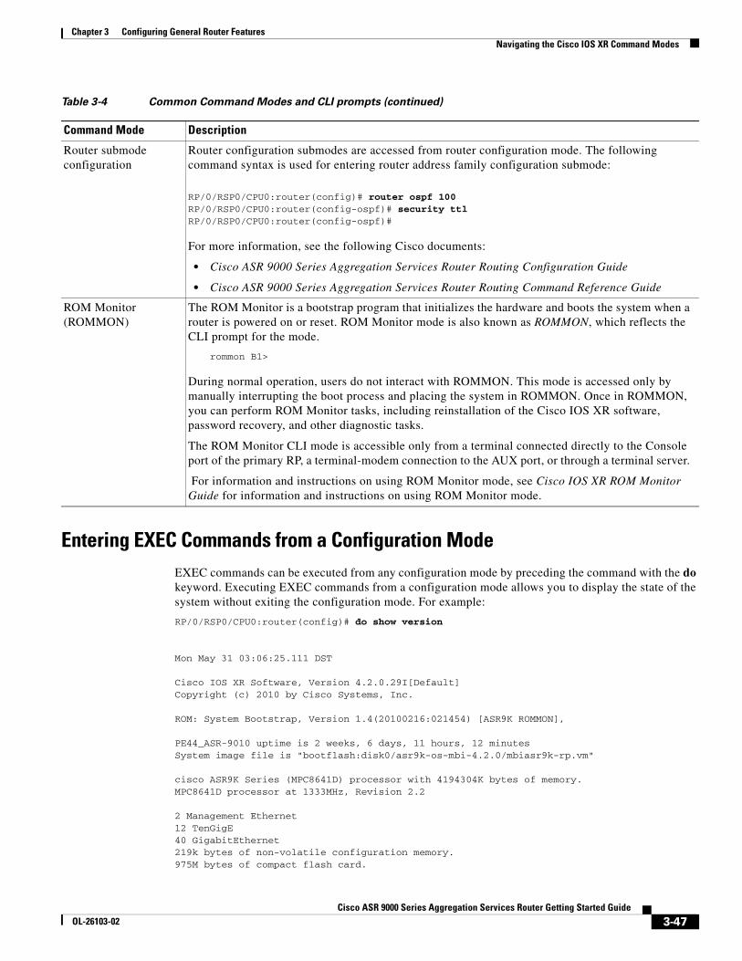
Entering EXEC Commands from a Configuration ModeEXEC commands can be executed from any configuration mode by preceding the command with the do keyword. Executing EXEC commands from a configuration mode allows you to display the state of the system without exiting the configuration mode. For example:
RP/0/RSP0/CPU0:router(config)# do show version
Mon May 31 03:06:25.111 DST
Cisco IOS XR Software, Version 4.2.0.29I[Default]Copyright (c) 2010 by Cisco Systems, Inc.
ROM: System Bootstrap, Version 1.4(20100216:021454) [ASR9K ROMMON],
PE44_ASR-9010 uptime is 2 weeks, 6 days, 11 hours, 12 minutesSystem image file is "bootflash:disk0/asr9k-os-mbi-4.2.0/mbiasr9k-rp.vm"
cisco ASR9K Series (MPC8641D) processor with 4194304K bytes of memory.MPC8641D processor at 1333MHz, Revision 2.2
2 Management Ethernet12 TenGigE40 GigabitEthernet219k bytes of non-volatile configuration memory.975M bytes of compact flash card.
Router submode configuration
Router configuration submodes are accessed from router configuration mode. The following command syntax is used for entering router address family configuration submode:
RP/0/RSP0/CPU0:router(config)# router ospf 100RP/0/RSP0/CPU0:router(config-ospf)# security ttlRP/0/RSP0/CPU0:router(config-ospf)#
For more information, see the following Cisco documents:
• Cisco ASR 9000 Series Aggregation Services Router Routing Configuration Guide
• Cisco ASR 9000 Series Aggregation Services Router Routing Command Reference Guide
ROM Monitor (ROMMON)
The ROM Monitor is a bootstrap program that initializes the hardware and boots the system when a router is powered on or reset. ROM Monitor mode is also known as ROMMON, which reflects the CLI prompt for the mode.
rommon B1>
During normal operation, users do not interact with ROMMON. This mode is accessed only by manually interrupting the boot process and placing the system in ROMMON. Once in ROMMON, you can perform ROM Monitor tasks, including reinstallation of the Cisco IOS XR software, password recovery, and other diagnostic tasks.
The ROM Monitor CLI mode is accessible only from a terminal connected directly to the Console port of the primary RP, a terminal-modem connection to the AUX port, or through a terminal server.
For information and instructions on using ROM Monitor mode, see Cisco IOS XR ROM Monitor Guide for information and instructions on using ROM Monitor mode.
Table 3-4 Common Command Modes and CLI prompts (continued)
Command Mode Description
3-47Cisco ASR 9000 Series Aggregation Services Router Getting Started Guide
OL-26103-02
Chapter 3 Configuring General Router Features Navigating the Cisco IOS XR Command Modes
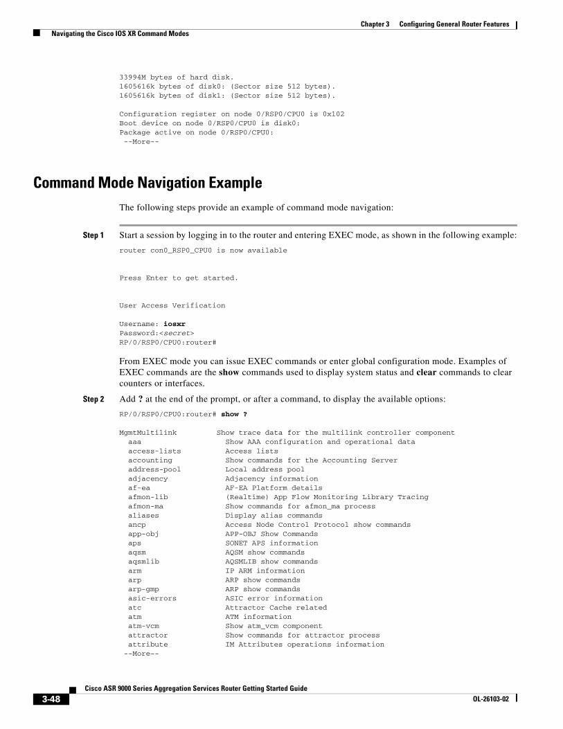
33994M bytes of hard disk.1605616k bytes of disk0: (Sector size 512 bytes).1605616k bytes of disk1: (Sector size 512 bytes).
Configuration register on node 0/RSP0/CPU0 is 0x102Boot device on node 0/RSP0/CPU0 is disk0:Package active on node 0/RSP0/CPU0: --More--
Command Mode Navigation ExampleThe following steps provide an example of command mode navigation:
Step 1 Start a session by logging in to the router and entering EXEC mode, as shown in the following example:
router con0_RSP0_CPU0 is now available
Press Enter to get started.
User Access Verification
Username: iosxrPassword:<secret>RP/0/RSP0/CPU0:router#
From EXEC mode you can issue EXEC commands or enter global configuration mode. Examples of EXEC commands are the show commands used to display system status and clear commands to clear counters or interfaces.
Step 2 Add ? at the end of the prompt, or after a command, to display the available options:
RP/0/RSP0/CPU0:router# show ?
MgmtMultilink Show trace data for the multilink controller component aaa Show AAA configuration and operational data access-lists Access lists accounting Show commands for the Accounting Server address-pool Local address pool adjacency Adjacency information af-ea AF-EA Platform details afmon-lib (Realtime) App Flow Monitoring Library Tracing afmon-ma Show commands for afmon_ma process aliases Display alias commands ancp Access Node Control Protocol show commands app-obj APP-OBJ Show Commands aps SONET APS information aqsm AQSM show commands aqsmlib AQSMLIB show commands arm IP ARM information arp ARP show commands arp-gmp ARP show commands asic-errors ASIC error information atc Attractor Cache related atm ATM information atm-vcm Show atm_vcm component attractor Show commands for attractor process attribute IM Attributes operations information --More--
3-48Cisco ASR 9000 Series Aggregation Services Router Getting Started Guide
OL-26103-02
Chapter 3 Configuring General Router Features Managing Configuration Sessions
Note The commands available depend on the router mode and your user group assignments.
Step 3 If you belong to a user group that has configuration privileges, you can place the router in the global configuration mode by entering the configure command:
RP/0/RSP0/CPU0:router# configureRP/0/RSP0/CPU0:router(config)#
Step 4 From global configuration mode, you can place the router in a configuration submode, such as interface configuration mode or a protocol-specific configuration mode:
RP/0/RSP0/CPU0:router# configureRP/0/RSP0/CPU0:router(config)# mpls ldpRP/0/RSP0/CPU0:router(config-ldp)#
In the following example, the router enters interface configuration mode and the user selects an MPLS Traffic Engineering Tunnel interface for configuration. The command syntax is interface type rack/slot/module/port.
RP/0/RSP0/CPU0:router(config)# interface tunnel-teRP/0/RSP0/CPU0:router(config-if)#
The command mode prompt changes from (config) to (config-if) and you can now enter configuration commands for the specified interface.
Step 5 To exit interface configuration mode and return to global configuration mode, enter the exit command. To return to EXEC mode, enter the end command.
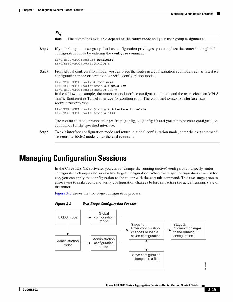
Managing Configuration SessionsIn the Cisco IOS XR software, you cannot change the running (active) configuration directly. Enter configuration changes into an inactive target configuration. When the target configuration is ready for use, you can apply that configuration to the router with the commit command. This two-stage process allows you to make, edit, and verify configuration changes before impacting the actual running state of the router.
Figure 3-3 shows the two-stage configuration process.
Figure 3-3 Two-Stage Configuration Process
EXEC modeGlobal
configurationmode
Administrationmode
Administrationconfiguration
mode
Stage 1:Enter configurationchanges or load asaved configuration.
Save configurationchanges to a file.
Stage 2:"Commit" changesto the runningconfiguration.
1499
46
3-49Cisco ASR 9000 Series Aggregation Services Router Getting Started Guide
OL-26103-02
Chapter 3 Configuring General Router Features Managing Configuration Sessions
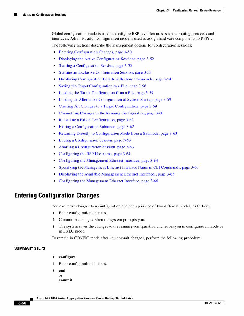
Global configuration mode is used to configure RSP-level features, such as routing protocols and interfaces. Administration configuration mode is used to assign hardware components to RSPs .
The following sections describe the management options for configuration sessions:
• Entering Configuration Changes, page 3-50
• Displaying the Active Configuration Sessions, page 3-52
• Starting a Configuration Session, page 3-53
• Starting an Exclusive Configuration Session, page 3-53
• Displaying Configuration Details with show Commands, page 3-54
• Saving the Target Configuration to a File, page 3-58
• Loading the Target Configuration from a File, page 3-59
• Loading an Alternative Configuration at System Startup, page 3-59
• Clearing All Changes to a Target Configuration, page 3-59
• Committing Changes to the Running Configuration, page 3-60
• Reloading a Failed Configuration, page 3-62
• Exiting a Configuration Submode, page 3-62
• Returning Directly to Configuration Mode from a Submode, page 3-63
• Ending a Configuration Session, page 3-63
• Aborting a Configuration Session, page 3-63
• Configuring the RSP Hostname, page 3-64
• Configuring the Management Ethernet Interface, page 3-64
• Specifying the Management Ethernet Interface Name in CLI Commands, page 3-65
• Displaying the Available Management Ethernet Interfaces, page 3-65
• Configuring the Management Ethernet Interface, page 3-66
Entering Configuration ChangesYou can make changes to a configuration and end up in one of two different modes, as follows:
1. Enter configuration changes.
2. Commit the changes when the system prompts you.
3. The system saves the changes to the running configuration and leaves you in configuration mode or in EXEC mode.
To remain in CONFIG mode after you commit changes, perform the following procedure:
SUMMARY STEPS
1. configure
2. Enter configuration changes.
3. endorcommit
3-50Cisco ASR 9000 Series Aggregation Services Router Getting Started Guide
OL-26103-02
Chapter 3 Configuring General Router Features Managing Configuration Sessions
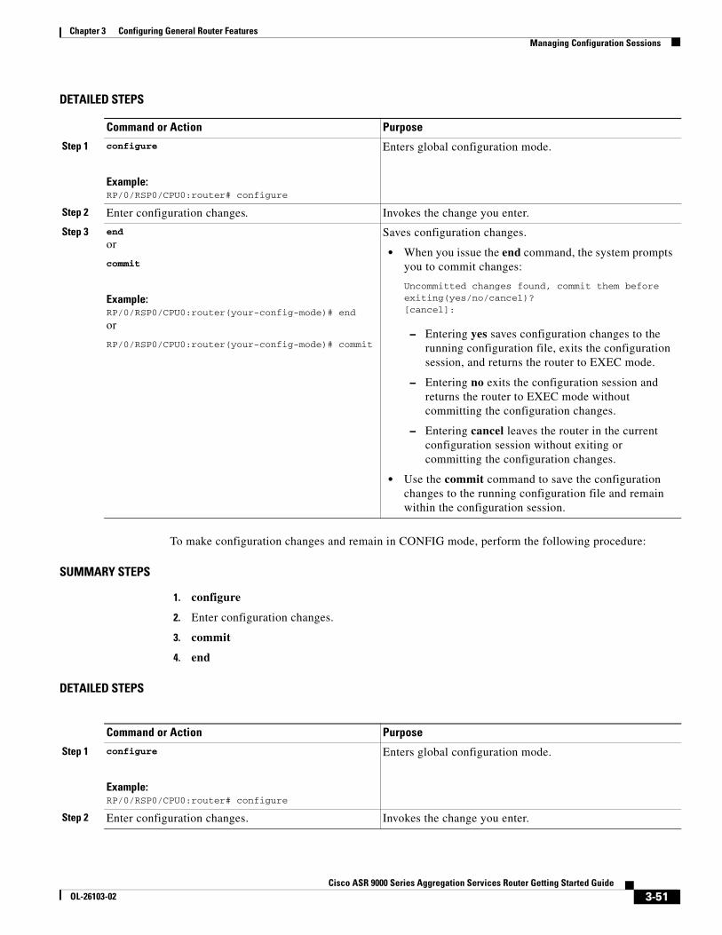
DETAILED STEPS
To make configuration changes and remain in CONFIG mode, perform the following procedure:
SUMMARY STEPS
1. configure
2. Enter configuration changes.
3. commit
4. end
DETAILED STEPS
Command or Action Purpose
Step 1 configure
Example:RP/0/RSP0/CPU0:router# configure
Enters global configuration mode.
Step 2 Enter configuration changes. Invokes the change you enter.
Step 3 end
or
commit
Example:RP/0/RSP0/CPU0:router(your-config-mode)# end
or
RP/0/RSP0/CPU0:router(your-config-mode)# commit
Saves configuration changes.
• When you issue the end command, the system prompts you to commit changes:
Uncommitted changes found, commit them before exiting(yes/no/cancel)?[cancel]:
– Entering yes saves configuration changes to the running configuration file, exits the configuration session, and returns the router to EXEC mode.
– Entering no exits the configuration session and returns the router to EXEC mode without committing the configuration changes.
– Entering cancel leaves the router in the current configuration session without exiting or committing the configuration changes.
• Use the commit command to save the configuration changes to the running configuration file and remain within the configuration session.
Command or Action Purpose
Step 1 configure
Example:RP/0/RSP0/CPU0:router# configure
Enters global configuration mode.
Step 2 Enter configuration changes. Invokes the change you enter.
3-51Cisco ASR 9000 Series Aggregation Services Router Getting Started Guide
OL-26103-02
Chapter 3 Configuring General Router Features Managing Configuration Sessions
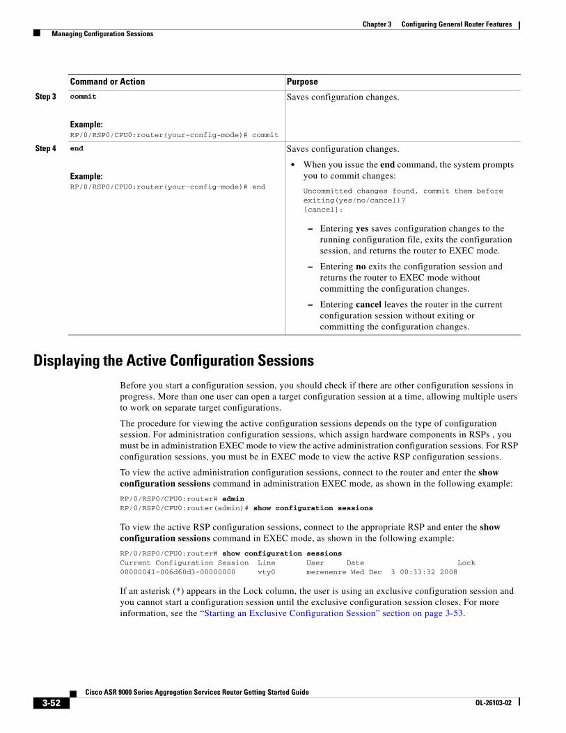
Displaying the Active Configuration SessionsBefore you start a configuration session, you should check if there are other configuration sessions in progress. More than one user can open a target configuration session at a time, allowing multiple users to work on separate target configurations.
The procedure for viewing the active configuration sessions depends on the type of configuration session. For administration configuration sessions, which assign hardware components in RSPs , you must be in administration EXEC mode to view the active administration configuration sessions. For RSP configuration sessions, you must be in EXEC mode to view the active RSP configuration sessions.
To view the active administration configuration sessions, connect to the router and enter the show configuration sessions command in administration EXEC mode, as shown in the following example:
RP/0/RSP0/CPU0:router# admin RP/0/RSP0/CPU0:router(admin)# show configuration sessions
To view the active RSP configuration sessions, connect to the appropriate RSP and enter the show configuration sessions command in EXEC mode, as shown in the following example:
RP/0/RSP0/CPU0:router# show configuration sessionsCurrent Configuration Session Line User Date Lock00000041-006d60d3-00000000 vty0 merenenre Wed Dec 3 00:33:32 2008
If an asterisk (*) appears in the Lock column, the user is using an exclusive configuration session and you cannot start a configuration session until the exclusive configuration session closes. For more information, see the “Starting an Exclusive Configuration Session” section on page 3-53.
Step 3 commit
Example:RP/0/RSP0/CPU0:router(your-config-mode)# commit
Saves configuration changes.
Step 4 end
Example:RP/0/RSP0/CPU0:router(your-config-mode)# end
Saves configuration changes.
• When you issue the end command, the system prompts you to commit changes:
Uncommitted changes found, commit them before exiting(yes/no/cancel)?[cancel]:
– Entering yes saves configuration changes to the running configuration file, exits the configuration session, and returns the router to EXEC mode.
– Entering no exits the configuration session and returns the router to EXEC mode without committing the configuration changes.
– Entering cancel leaves the router in the current configuration session without exiting or committing the configuration changes.
Command or Action Purpose
3-52Cisco ASR 9000 Series Aggregation Services Router Getting Started Guide
OL-26103-02
Chapter 3 Configuring General Router Features Managing Configuration Sessions
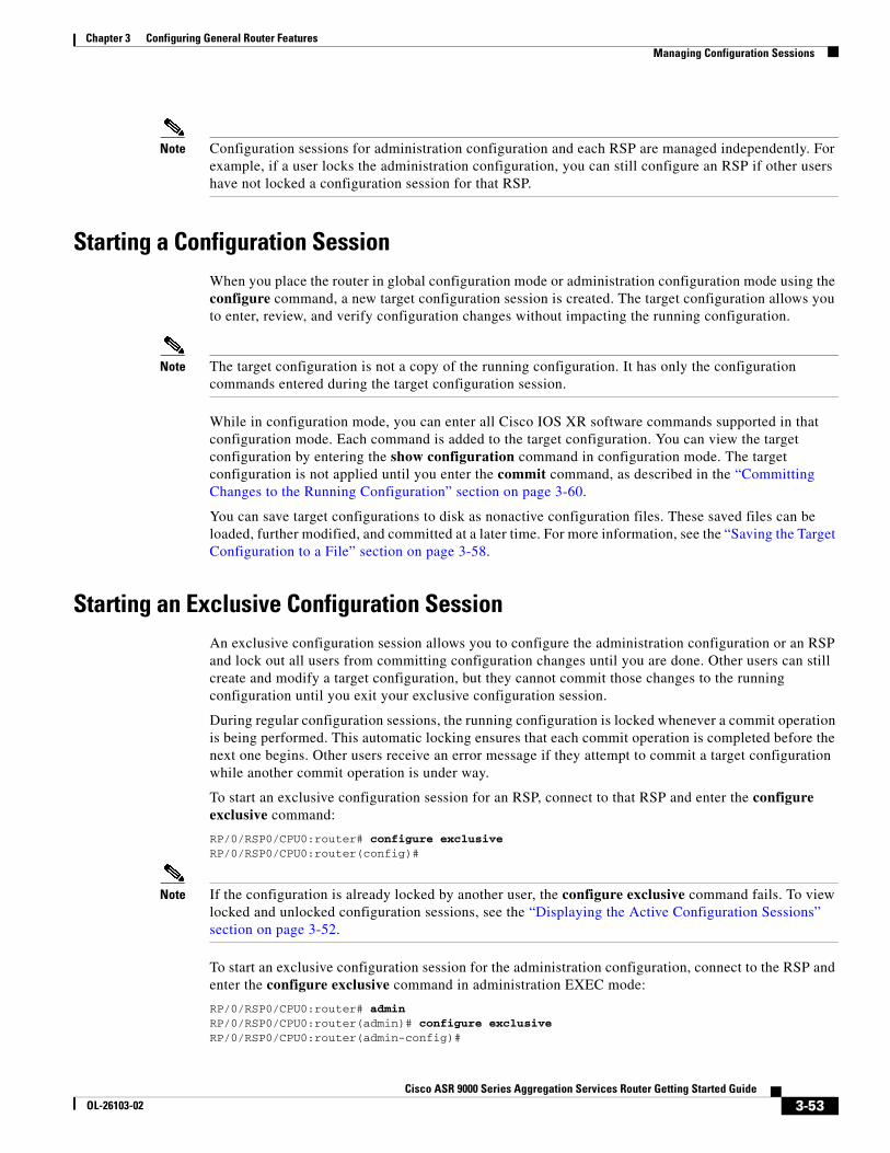
Note Configuration sessions for administration configuration and each RSP are managed independently. For example, if a user locks the administration configuration, you can still configure an RSP if other users have not locked a configuration session for that RSP.
Starting a Configuration SessionWhen you place the router in global configuration mode or administration configuration mode using the configure command, a new target configuration session is created. The target configuration allows you to enter, review, and verify configuration changes without impacting the running configuration.
Note The target configuration is not a copy of the running configuration. It has only the configuration commands entered during the target configuration session.
While in configuration mode, you can enter all Cisco IOS XR software commands supported in that configuration mode. Each command is added to the target configuration. You can view the target configuration by entering the show configuration command in configuration mode. The target configuration is not applied until you enter the commit command, as described in the “Committing Changes to the Running Configuration” section on page 3-60.
You can save target configurations to disk as nonactive configuration files. These saved files can be loaded, further modified, and committed at a later time. For more information, see the “Saving the Target Configuration to a File” section on page 3-58.
Starting an Exclusive Configuration SessionAn exclusive configuration session allows you to configure the administration configuration or an RSP and lock out all users from committing configuration changes until you are done. Other users can still create and modify a target configuration, but they cannot commit those changes to the running configuration until you exit your exclusive configuration session.
During regular configuration sessions, the running configuration is locked whenever a commit operation is being performed. This automatic locking ensures that each commit operation is completed before the next one begins. Other users receive an error message if they attempt to commit a target configuration while another commit operation is under way.
To start an exclusive configuration session for an RSP, connect to that RSP and enter the configure exclusive command:
RP/0/RSP0/CPU0:router# configure exclusiveRP/0/RSP0/CPU0:router(config)#
Note If the configuration is already locked by another user, the configure exclusive command fails. To view locked and unlocked configuration sessions, see the “Displaying the Active Configuration Sessions” section on page 3-52.
To start an exclusive configuration session for the administration configuration, connect to the RSP and enter the configure exclusive command in administration EXEC mode:
RP/0/RSP0/CPU0:router# adminRP/0/RSP0/CPU0:router(admin)# configure exclusiveRP/0/RSP0/CPU0:router(admin-config)#
3-53Cisco ASR 9000 Series Aggregation Services Router Getting Started Guide
OL-26103-02
Chapter 3 Configuring General Router Features Managing Configuration Sessions
The running configuration is unlocked when the user who started the exclusive configuration session exits the configuration mode, as described in the “Ending a Configuration Session” section on page 3-63.
Displaying Configuration Details with show CommandsThe following sections describe the following tasks:
• Displaying the Running Configuration, page 3-54
• Displaying a Sanitized Version of the Running Configuration, page 3-55
• Displaying the Target Configuration, page 3-56
• Displaying a Combined Target and Running Configuration, page 3-56
• Displaying Configuration Error Messages and Descriptions, page 3-57
• Displaying Configuration Error Messages Without Descriptions, page 3-58
• Displaying Configuration Error Messages Produced While Loading a Configuration, page 3-58
Displaying the Running Configuration
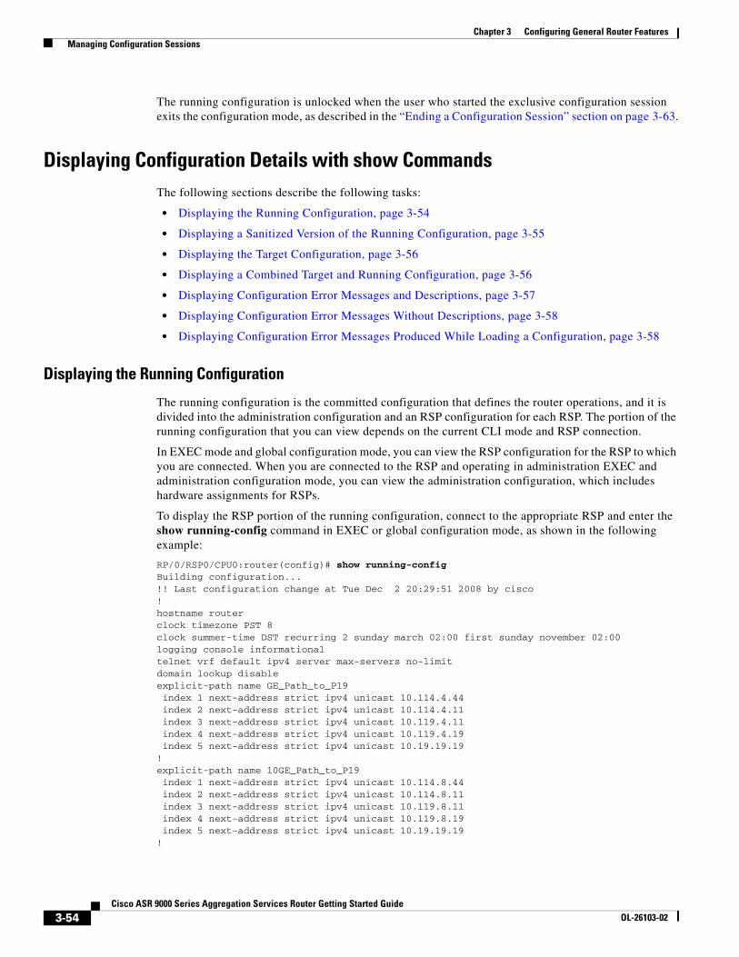
The running configuration is the committed configuration that defines the router operations, and it is divided into the administration configuration and an RSP configuration for each RSP. The portion of the running configuration that you can view depends on the current CLI mode and RSP connection.
In EXEC mode and global configuration mode, you can view the RSP configuration for the RSP to which you are connected. When you are connected to the RSP and operating in administration EXEC and administration configuration mode, you can view the administration configuration, which includes hardware assignments for RSPs.
To display the RSP portion of the running configuration, connect to the appropriate RSP and enter the show running-config command in EXEC or global configuration mode, as shown in the following example:
RP/0/RSP0/CPU0:router(config)# show running-configBuilding configuration...!! Last configuration change at Tue Dec 2 20:29:51 2008 by cisco!hostname routerclock timezone PST 8clock summer-time DST recurring 2 sunday march 02:00 first sunday november 02:00logging console informationaltelnet vrf default ipv4 server max-servers no-limitdomain lookup disableexplicit-path name GE_Path_to_P19 index 1 next-address strict ipv4 unicast 10.114.4.44 index 2 next-address strict ipv4 unicast 10.114.4.11 index 3 next-address strict ipv4 unicast 10.119.4.11 index 4 next-address strict ipv4 unicast 10.119.4.19 index 5 next-address strict ipv4 unicast 10.19.19.19!explicit-path name 10GE_Path_to_P19 index 1 next-address strict ipv4 unicast 10.114.8.44 index 2 next-address strict ipv4 unicast 10.114.8.11 index 3 next-address strict ipv4 unicast 10.119.8.11 index 4 next-address strict ipv4 unicast 10.119.8.19 index 5 next-address strict ipv4 unicast 10.19.19.19!
3-54Cisco ASR 9000 Series Aggregation Services Router Getting Started Guide
OL-26103-02
Chapter 3 Configuring General Router Features Managing Configuration Sessions
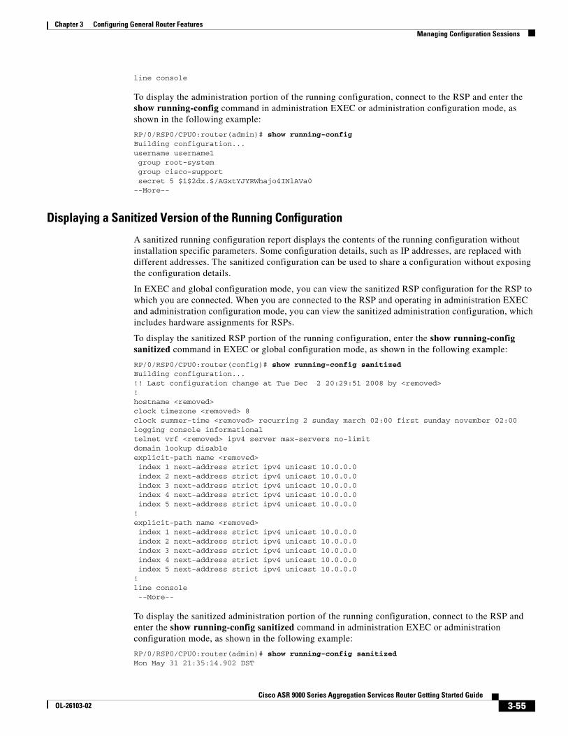
line console
To display the administration portion of the running configuration, connect to the RSP and enter the show running-config command in administration EXEC or administration configuration mode, as shown in the following example:
RP/0/RSP0/CPU0:router(admin)# show running-config Building configuration...username username1 group root-system group cisco-support secret 5 $1$2dx.$/AGxtYJYRWhajo4INlAVa0--More--
Displaying a Sanitized Version of the Running Configuration
A sanitized running configuration report displays the contents of the running configuration without installation specific parameters. Some configuration details, such as IP addresses, are replaced with different addresses. The sanitized configuration can be used to share a configuration without exposing the configuration details.
In EXEC and global configuration mode, you can view the sanitized RSP configuration for the RSP to which you are connected. When you are connected to the RSP and operating in administration EXEC and administration configuration mode, you can view the sanitized administration configuration, which includes hardware assignments for RSPs.
To display the sanitized RSP portion of the running configuration, enter the show running-config sanitized command in EXEC or global configuration mode, as shown in the following example:
RP/0/RSP0/CPU0:router(config)# show running-config sanitizedBuilding configuration...!! Last configuration change at Tue Dec 2 20:29:51 2008 by <removed>!hostname <removed>clock timezone <removed> 8clock summer-time <removed> recurring 2 sunday march 02:00 first sunday november 02:00logging console informationaltelnet vrf <removed> ipv4 server max-servers no-limitdomain lookup disableexplicit-path name <removed> index 1 next-address strict ipv4 unicast 10.0.0.0 index 2 next-address strict ipv4 unicast 10.0.0.0 index 3 next-address strict ipv4 unicast 10.0.0.0 index 4 next-address strict ipv4 unicast 10.0.0.0 index 5 next-address strict ipv4 unicast 10.0.0.0!explicit-path name <removed> index 1 next-address strict ipv4 unicast 10.0.0.0 index 2 next-address strict ipv4 unicast 10.0.0.0 index 3 next-address strict ipv4 unicast 10.0.0.0 index 4 next-address strict ipv4 unicast 10.0.0.0 index 5 next-address strict ipv4 unicast 10.0.0.0!line console --More--
To display the sanitized administration portion of the running configuration, connect to the RSP and enter the show running-config sanitized command in administration EXEC or administration configuration mode, as shown in the following example:
RP/0/RSP0/CPU0:router(admin)# show running-config sanitizedMon May 31 21:35:14.902 DST
3-55Cisco ASR 9000 Series Aggregation Services Router Getting Started Guide
OL-26103-02
Chapter 3 Configuring General Router Features Managing Configuration Sessions
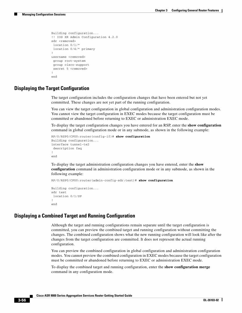
Building configuration...!! IOS XR Admin Configuration 4.2.0sdr <removed> location 0/1/* location 0/4/* primary!username <removed> group root-system group cisco-support secret 5 <removed>!end
Displaying the Target Configuration
The target configuration includes the configuration changes that have been entered but not yet committed. These changes are not yet part of the running configuration.
You can view the target configuration in global configuration and administration configuration modes. You cannot view the target configuration in EXEC modes because the target configuration must be committed or abandoned before returning to EXEC or administration EXEC mode.
To display the target configuration changes you have entered for an RSP, enter the show configuration command in global configuration mode or in any submode, as shown in the following example:
RP/0/RSP0/CPU0:router(config-if)# show configuration Building configuration...interface tunnel-te2 description faq!end
To display the target administration configuration changes you have entered, enter the show configuration command in administration configuration mode or in any submode, as shown in the following example:
RP/0/RSP0/CPU0:router(admin-config-sdr:test)# show configuration
Building configuration...sdr test location 0/1/SP !end
Displaying a Combined Target and Running Configuration
Although the target and running configurations remain separate until the target configuration is committed, you can preview the combined target and running configuration without committing the changes. The combined configuration shows what the new running configuration will look like after the changes from the target configuration are committed. It does not represent the actual running configuration.
You can preview the combined configuration in global configuration and administration configuration modes. You cannot preview the combined configuration in EXEC modes because the target configuration must be committed or abandoned before returning to EXEC or administration EXEC mode.
To display the combined target and running configuration, enter the show configuration merge command in any configuration mode.
3-56Cisco ASR 9000 Series Aggregation Services Router Getting Started Guide
OL-26103-02
Chapter 3 Configuring General Router Features Managing Configuration Sessions
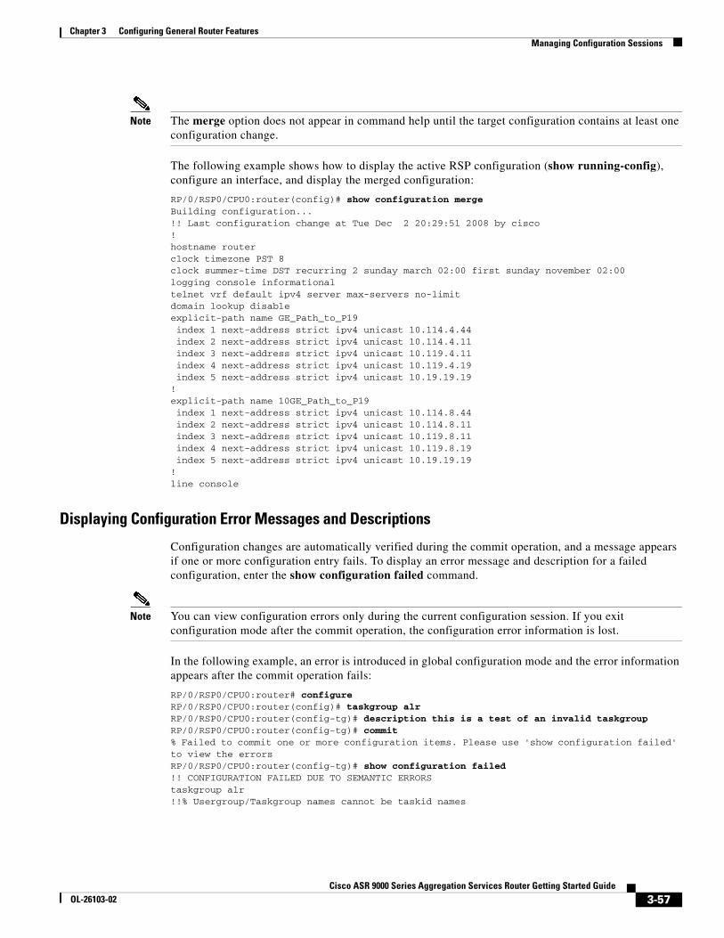
Note The merge option does not appear in command help until the target configuration contains at least one configuration change.
The following example shows how to display the active RSP configuration (show running-config), configure an interface, and display the merged configuration:
RP/0/RSP0/CPU0:router(config)# show configuration mergeBuilding configuration...!! Last configuration change at Tue Dec 2 20:29:51 2008 by cisco!hostname routerclock timezone PST 8clock summer-time DST recurring 2 sunday march 02:00 first sunday november 02:00logging console informationaltelnet vrf default ipv4 server max-servers no-limitdomain lookup disableexplicit-path name GE_Path_to_P19 index 1 next-address strict ipv4 unicast 10.114.4.44 index 2 next-address strict ipv4 unicast 10.114.4.11 index 3 next-address strict ipv4 unicast 10.119.4.11 index 4 next-address strict ipv4 unicast 10.119.4.19 index 5 next-address strict ipv4 unicast 10.19.19.19!explicit-path name 10GE_Path_to_P19 index 1 next-address strict ipv4 unicast 10.114.8.44 index 2 next-address strict ipv4 unicast 10.114.8.11 index 3 next-address strict ipv4 unicast 10.119.8.11 index 4 next-address strict ipv4 unicast 10.119.8.19 index 5 next-address strict ipv4 unicast 10.19.19.19!line console
Displaying Configuration Error Messages and Descriptions
Configuration changes are automatically verified during the commit operation, and a message appears if one or more configuration entry fails. To display an error message and description for a failed configuration, enter the show configuration failed command.
Note You can view configuration errors only during the current configuration session. If you exit configuration mode after the commit operation, the configuration error information is lost.
In the following example, an error is introduced in global configuration mode and the error information appears after the commit operation fails:
RP/0/RSP0/CPU0:router# configureRP/0/RSP0/CPU0:router(config)# taskgroup alrRP/0/RSP0/CPU0:router(config-tg)# description this is a test of an invalid taskgroupRP/0/RSP0/CPU0:router(config-tg)# commit% Failed to commit one or more configuration items. Please use 'show configuration failed' to view the errorsRP/0/RSP0/CPU0:router(config-tg)# show configuration failed!! CONFIGURATION FAILED DUE TO SEMANTIC ERRORStaskgroup alr!!% Usergroup/Taskgroup names cannot be taskid names
3-57Cisco ASR 9000 Series Aggregation Services Router Getting Started Guide
OL-26103-02
Chapter 3 Configuring General Router Features Managing Configuration Sessions
Displaying Configuration Error Messages Without Descriptions
Configuration changes are automatically verified during the commit operation, and a message appears if one or more configuration entry fails. To display only the error message (without a description) for a failed configuration, enter the show configuration failed noerror command, as shown in the following example:
RP/0/RSP0/CPU0:router(config-tg)# show configuration failed noerror!! CONFIGURATION FAILED DUE TO SEMANTIC ERRORStaskgroup alr!
Note You can view configuration errors only during the current configuration session. If you exit configuration mode after the commit operation, the configuration error information is lost.
Displaying Configuration Error Messages Produced While Loading a Configuration
To display any syntax errors found in a configuration loaded with the load command, enter the show configuration failed load command.
Saving the Target Configuration to a FileTarget configurations can be saved to a separate file without committing them to the running configuration. Target configuration files can then be loaded at a later time and further modified or committed.
To save the configuration changes in the target configuration to a file, enter the save configuration device: command. Replace the device argument with the name of the device on which you want to store the file (for example, disk0). After you enter this command, the router prompts you to enter a filename. If you enter only a filename, the file is stored in the root directory of the device. To store the file in a directory, enter the directory path and filename when prompted. We recommend that you specify the cfg file extension for easy identification. This suffix is not required, but it can help locate target configuration files, for example:
myconfig.cfg
The following example shows a target configuration file saved to the usr/cisco directory of disk0:
RP/0/RSP1/CPU0:router(admin-config)# save configuration disk0:
Mon May 31 21:52:13.237 DSTDestination file name (control-c to abort): [/running-config]?/usr/cisco/test.cfgBuilding configuration.1 lines built in 1 second[OK]
You can also save a configuration to a file using the show configuration | file filename command.
RP/0/RSP1/CPU0:router(config)#show configuration | file abc.cfgThu Jul 22 23:03:04.722 DSTBuilding configuration...
[OK]
3-58Cisco ASR 9000 Series Aggregation Services Router Getting Started Guide
OL-26103-02
Chapter 3 Configuring General Router Features Managing Configuration Sessions
Loading the Target Configuration from a FileTo populate the target configuration with the contents of a previously saved configuration file, go to global configuration or administration configuration mode and enter the load filename command. Consider the following when entering the filename argument:
• Specifies the configuration file to be loaded into the target configuration.
• If the full path of the file is not specified, the router attempts to load the file from the root directory on the device.
The following example shows a target configuration file loaded into the current configuration session. The current configuration session is populated with the contents of the file.
RP/0/RSP1/CPU0:router(config)# load disk0:/usr/cisco/test.cfg
Loading.77 bytes parsed in 1 sec (76)bytes/sec
Loading an Alternative Configuration at System StartupWhen a router is reset or powered on, the last running configuration is loaded and used to operate the router.
You can load an alternative configuration during system boot. For information and instructions on this process, see the Cisco ASR 9000 Series Aggregation Services Router ROM Monitor Guide.
Clearing All Changes to a Target ConfigurationTo clear changes made to the target configuration without terminating the configuration session, enter the clear command in global configuration mode or administration configuration mode. This command deletes any configuration changes that have not been committed.
In the following example, the user configures an interface but does not commit it. After reviewing the changes to the target configuration with the show configuration command, the user decides to remove the changes and start over by entering the clear command:
RP/0/RSP0/CPU0:router# configure RP/0/RSP0/CPU0:router(config)# interface Gi 0/3/0/1 RP/0/RSP0/CPU0:router(config-if)# description this is my interface RP/0/RSP0/CPU0:router(config-if)# ipv4 address 10.1.1.1 255.0.0.0 RP/0/RSP0/CPU0:router(config-if)# shutdown RP/0/RSP0/CPU0:router(config-if)# exit
RP/0/RSP0/CPU0:router(config)# show configuration
Building configuration... interface Gi0/3/0/1 description this is my interface ipv4 address 10.1.1.1 255.0.0.0 shutdown end
RP/0/RSP0/CPU0:router(config)# clear RP/0/RSP0/CPU0:router(config)# show configurationBuilding configuration... end
3-59Cisco ASR 9000 Series Aggregation Services Router Getting Started Guide
OL-26103-02
Chapter 3 Configuring General Router Features Managing Configuration Sessions
Committing Changes to the Running ConfigurationThe changes in the target configuration do not become part of the running configuration until you enter the commit command. When you commit a target configuration, you can use the commit command to do either of the following:
• Merge the target configuration with the running configuration to create a new running configuration.
• Replace the running configuration with the target configuration.
Note If you try to end a configuration session without saving your changes to the running configuration with the commit command, you are prompted to save the changes. For more information, see the “Ending a Configuration Session” section on page 3-63.
To commit target configuration changes to the running configuration, enter the commit command by itself or with one or more of the options described in Table 3-5.
Table 3-5 Commit Command Options
Command Description
commit (Default) Merges the target configuration with the running configuration and commits changes only if all changes in the target configuration pass the semantic verification process. If any semantic errors are found, none of the configuration changes takes effect.
commit best-effort Merges the target configuration with the running configuration and commits only valid changes (best effort). Some configuration changes might fail due to semantic errors.
commit comment line (Optional) Assigns a comment to a commit.
• This text comment appears in the commit entry displayed with the show configuration commit list [detail] command.
• The line argument is the text for the optional comment or label.
• The comment option must appear at the end of the command line. If multiple options are entered, all text after the comment option is treated as a comment.
commit confirmed seconds
(Optional) Commits the configuration in global configuration mode on a trial basis for a minimum of 30 seconds and a maximum of 300 seconds (5 minutes).
• During the trial configuration, enter commit to confirm the configuration. If you do not enter the commit command, the router reverts to the previous configuration when the trial time period expires.
• The confirmed option is not available in administration configuration mode.
commit label line (Optional) Assigns a meaningful label. This label appears in the output for the show configuration commit list [detail] command instead of the numeric label.
• The line argument is the text for the optional comment or label.
3-60Cisco ASR 9000 Series Aggregation Services Router Getting Started Guide
OL-26103-02
Chapter 3 Configuring General Router Features Managing Configuration Sessions
Examples
The following examples illustrate how to commit a configuration:
• Committing a Configuration from Global Configuration Mode: Example, page 3-61
• Committing a Configuration from Administration Configuration Mode: Example, page 3-61
Committing a Configuration from Global Configuration Mode: Example
In the following example, the default commit command is entered in global configuration mode:
RP/0/RSP0/CPU0:router# configure RP/0/RSP0/CPU0:router(config)# interface GigabitEthernet 0/0/0/2RP/0/RSP0/CPU0:router(config-if)# description faq RP/0/RSP0/CPU0:router(config-if)# ipv4 address 10.1.1.1 255.0.0.0 RP/0/RSP0/CPU0:router(config-if)# commit
RP/0/0/0:Aug 6 09:26:17.781 : %LIBTARCFG-6-COMMIT Configuration committed by user ‘cisco'. Use 'show configuration commit changes 1000000124' to view the changes.
Note The preceding message is stored in the log and appears only if logging is configured to display on screen.
Committing a Configuration from Administration Configuration Mode: Example
In the following example, the commit command is entered with the label and comment keywords in administration configuration mode:
RP/0/RSP0/CPU0:router# adminRP/0/RSP0/CPU0:router(admin)# configure RP/0/RSP0/CPU0:router(admin-config)# sdr testRP/0/RSP0/CPU0:router(admin-config-sdr:test)# location 0/1/* primaryRP/0/RSP0/CPU0:router(admin-config-sdr:test)# commit label test comment This is a testRP/0/RSP0/CPU0:router(admin-config)# show configuration commit list detail
1) CommitId: 2000000018 Label: test
commit force (Optional) Merges the target configuration with the running configuration and allows a configuration commit in low-memory conditions.
A low-memory warning occurs when a user attempts to commit a target configuration that exceeds the default capacity of the router.
The recommended resolution to such a warning is to remove configurations using the no commands.
Caution The force option can cause the router to experience severe problems if low-memory conditions occur. The force option should be used only to remove configurations.
commit replace (Optional) Replaces the contents of the running configuration with the target configuration.
Table 3-5 Commit Command Options (continued)
Command Description
3-61Cisco ASR 9000 Series Aggregation Services Router Getting Started Guide
OL-26103-02
Chapter 3 Configuring General Router Features Managing Configuration Sessions
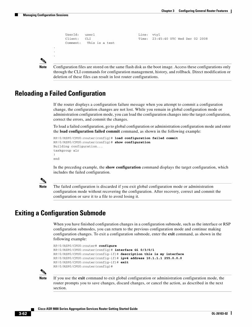
UserId: user1 Line: vty1 Client: CLI Time: 23:45:40 UTC Wed Dec 02 2008 Comment: This is a test ...
Note Configuration files are stored on the same flash disk as the boot image. Access these configurations only through the CLI commands for configuration management, history, and rollback. Direct modification or deletion of these files can result in lost router configurations.
Reloading a Failed ConfigurationIf the router displays a configuration failure message when you attempt to commit a configuration change, the configuration changes are not lost. While you remain in global configuration mode or administration configuration mode, you can load the configuration changes into the target configuration, correct the errors, and commit the changes.
To load a failed configuration, go to global configuration or administration configuration mode and enter the load configuration failed commit command, as shown in the following example:
RP/0/RSP0/CPU0:router(config)# load configuration failed commitRP/0/RSP0/CPU0:router(config)# show configurationBuilding configuration...taskgroup alr!end
In the preceding example, the show configuration command displays the target configuration, which includes the failed configuration.
Note The failed configuration is discarded if you exit global configuration mode or administration configuration mode without recovering the configuration. After recovery, correct and commit the configuration or save it to a file to avoid losing it.
Exiting a Configuration SubmodeWhen you have finished configuration changes in a configuration submode, such as the interface or RSP configuration submodes, you can return to the previous configuration mode and continue making configuration changes. To exit a configuration submode, enter the exit command, as shown in the following example:
RP/0/RSP0/CPU0:router# configure RP/0/RSP0/CPU0:router(config)# interface Gi 0/3/0/1 RP/0/RSP0/CPU0:router(config-if)# description this is my interface RP/0/RSP0/CPU0:router(config-if)# ipv4 address 10.1.1.1 255.0.0.0 RP/0/RSP0/CPU0:router(config-if)# exit RP/0/RSP0/CPU0:router(config)#
Note If you use the exit command to exit global configuration or administration configuration mode, the router prompts you to save changes, discard changes, or cancel the action, as described in the next section.
3-62Cisco ASR 9000 Series Aggregation Services Router Getting Started Guide
OL-26103-02
Chapter 3 Configuring General Router Features Managing Configuration Sessions
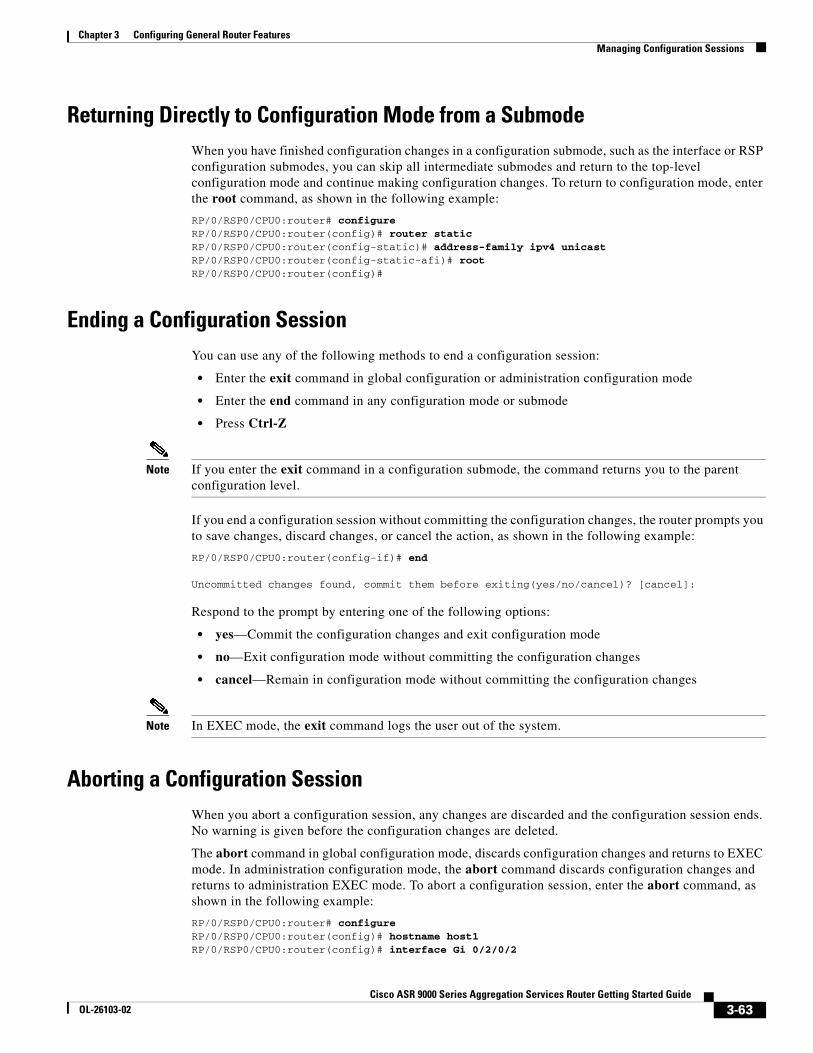
Returning Directly to Configuration Mode from a SubmodeWhen you have finished configuration changes in a configuration submode, such as the interface or RSP configuration submodes, you can skip all intermediate submodes and return to the top-level configuration mode and continue making configuration changes. To return to configuration mode, enter the root command, as shown in the following example:
RP/0/RSP0/CPU0:router# configureRP/0/RSP0/CPU0:router(config)# router static RP/0/RSP0/CPU0:router(config-static)# address-family ipv4 unicast RP/0/RSP0/CPU0:router(config-static-afi)# rootRP/0/RSP0/CPU0:router(config)#
Ending a Configuration SessionYou can use any of the following methods to end a configuration session:
• Enter the exit command in global configuration or administration configuration mode
• Enter the end command in any configuration mode or submode
• Press Ctrl-Z
Note If you enter the exit command in a configuration submode, the command returns you to the parent configuration level.
If you end a configuration session without committing the configuration changes, the router prompts you to save changes, discard changes, or cancel the action, as shown in the following example:
RP/0/RSP0/CPU0:router(config-if)# end
Uncommitted changes found, commit them before exiting(yes/no/cancel)? [cancel]:
Respond to the prompt by entering one of the following options:
• yes—Commit the configuration changes and exit configuration mode
• no—Exit configuration mode without committing the configuration changes
• cancel—Remain in configuration mode without committing the configuration changes
Note In EXEC mode, the exit command logs the user out of the system.
Aborting a Configuration SessionWhen you abort a configuration session, any changes are discarded and the configuration session ends. No warning is given before the configuration changes are deleted.
The abort command in global configuration mode, discards configuration changes and returns to EXEC mode. In administration configuration mode, the abort command discards configuration changes and returns to administration EXEC mode. To abort a configuration session, enter the abort command, as shown in the following example:
RP/0/RSP0/CPU0:router# configureRP/0/RSP0/CPU0:router(config)# hostname host1 RP/0/RSP0/CPU0:router(config)# interface Gi 0/2/0/2
3-63Cisco ASR 9000 Series Aggregation Services Router Getting Started Guide
OL-26103-02
Chapter 3 Configuring General Router Features Configuring the RSP Hostname
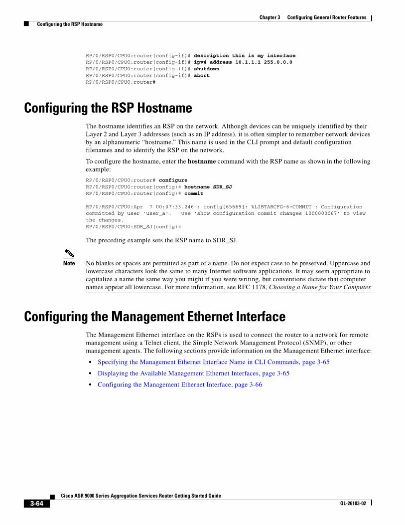
RP/0/RSP0/CPU0:router(config-if)# description this is my interface RP/0/RSP0/CPU0:router(config-if)# ipv4 address 10.1.1.1 255.0.0.0 RP/0/RSP0/CPU0:router(config-if)# shutdown RP/0/RSP0/CPU0:router(config-if)# abort RP/0/RSP0/CPU0:router#
Configuring the RSP HostnameThe hostname identifies an RSP on the network. Although devices can be uniquely identified by their Layer 2 and Layer 3 addresses (such as an IP address), it is often simpler to remember network devices by an alphanumeric “hostname.” This name is used in the CLI prompt and default configuration filenames and to identify the RSP on the network.
To configure the hostname, enter the hostname command with the RSP name as shown in the following example:
RP/0/RSP0/CPU0:router# configureRP/0/RSP0/CPU0:router(config)# hostname SDR_SJRP/0/RSP0/CPU0:router(config)# commit
RP/0/RSP0/CPU0:Apr 7 00:07:33.246 : config[65669]: %LIBTARCFG-6-COMMIT : Configuration committed by user 'user_a'. Use 'show configuration commit changes 1000000067' to view the changes.RP/0/RSP0/CPU0:SDR_SJ(config)#
The preceding example sets the RSP name to SDR_SJ.
Note No blanks or spaces are permitted as part of a name. Do not expect case to be preserved. Uppercase and lowercase characters look the same to many Internet software applications. It may seem appropriate to capitalize a name the same way you might if you were writing, but conventions dictate that computer names appear all lowercase. For more information, see RFC 1178, Choosing a Name for Your Computer.
Configuring the Management Ethernet InterfaceThe Management Ethernet interface on the RSPs is used to connect the router to a network for remote management using a Telnet client, the Simple Network Management Protocol (SNMP), or other management agents. The following sections provide information on the Management Ethernet interface:
• Specifying the Management Ethernet Interface Name in CLI Commands, page 3-65
• Displaying the Available Management Ethernet Interfaces, page 3-65
• Configuring the Management Ethernet Interface, page 3-66
3-64Cisco ASR 9000 Series Aggregation Services Router Getting Started Guide
OL-26103-02
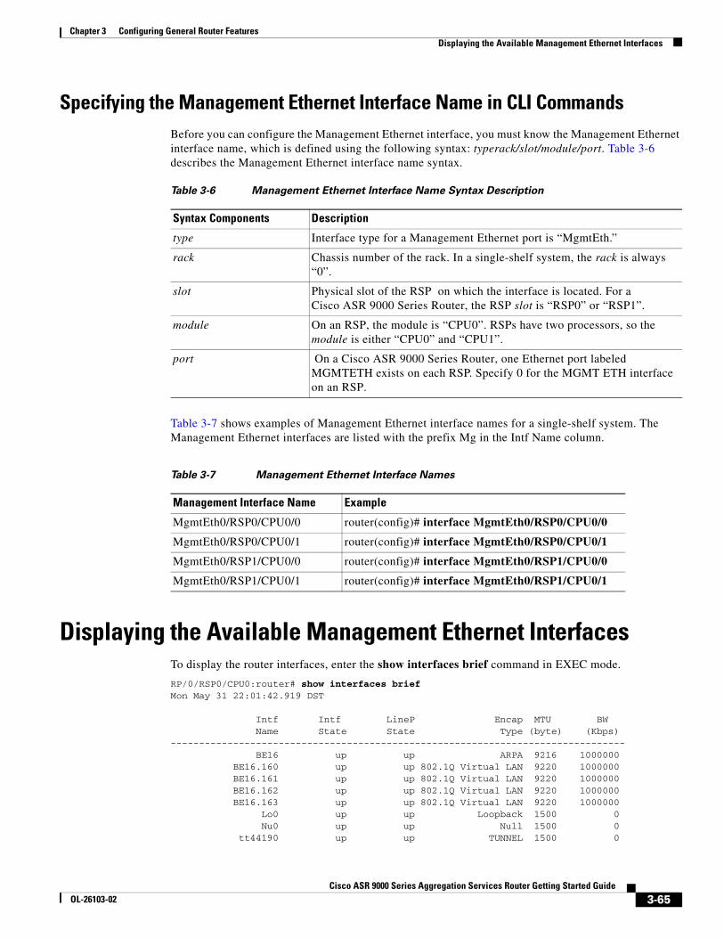
Chapter 3 Configuring General Router Features Displaying the Available Management Ethernet Interfaces
Specifying the Management Ethernet Interface Name in CLI CommandsBefore you can configure the Management Ethernet interface, you must know the Management Ethernet interface name, which is defined using the following syntax: typerack/slot/module/port. Table 3-6 describes the Management Ethernet interface name syntax.
Table 3-7 shows examples of Management Ethernet interface names for a single-shelf system. The Management Ethernet interfaces are listed with the prefix Mg in the Intf Name column.
Displaying the Available Management Ethernet Interfaces To display the router interfaces, enter the show interfaces brief command in EXEC mode.
RP/0/RSP0/CPU0:router# show interfaces briefMon May 31 22:01:42.919 DST
Intf Intf LineP Encap MTU BW Name State State Type (byte) (Kbps)-------------------------------------------------------------------------------- BE16 up up ARPA 9216 1000000 BE16.160 up up 802.1Q Virtual LAN 9220 1000000 BE16.161 up up 802.1Q Virtual LAN 9220 1000000 BE16.162 up up 802.1Q Virtual LAN 9220 1000000 BE16.163 up up 802.1Q Virtual LAN 9220 1000000 Lo0 up up Loopback 1500 0 Nu0 up up Null 1500 0 tt44190 up up TUNNEL 1500 0
Table 3-6 Management Ethernet Interface Name Syntax Description
Syntax Components Description
type Interface type for a Management Ethernet port is “MgmtEth.”
rack Chassis number of the rack. In a single-shelf system, the rack is always “0”.
slot Physical slot of the RSP on which the interface is located. For a Cisco ASR 9000 Series Router, the RSP slot is “RSP0” or “RSP1”.
module On an RSP, the module is “CPU0”. RSPs have two processors, so the module is either “CPU0” and “CPU1”.
port On a Cisco ASR 9000 Series Router, one Ethernet port labeled MGMTETH exists on each RSP. Specify 0 for the MGMT ETH interface on an RSP.
Table 3-7 Management Ethernet Interface Names
Management Interface Name Example
MgmtEth0/RSP0/CPU0/0 router(config)# interface MgmtEth0/RSP0/CPU0/0
MgmtEth0/RSP0/CPU0/1 router(config)# interface MgmtEth0/RSP0/CPU0/1
MgmtEth0/RSP1/CPU0/0 router(config)# interface MgmtEth0/RSP1/CPU0/0
MgmtEth0/RSP1/CPU0/1 router(config)# interface MgmtEth0/RSP1/CPU0/1
3-65Cisco ASR 9000 Series Aggregation Services Router Getting Started Guide
OL-26103-02
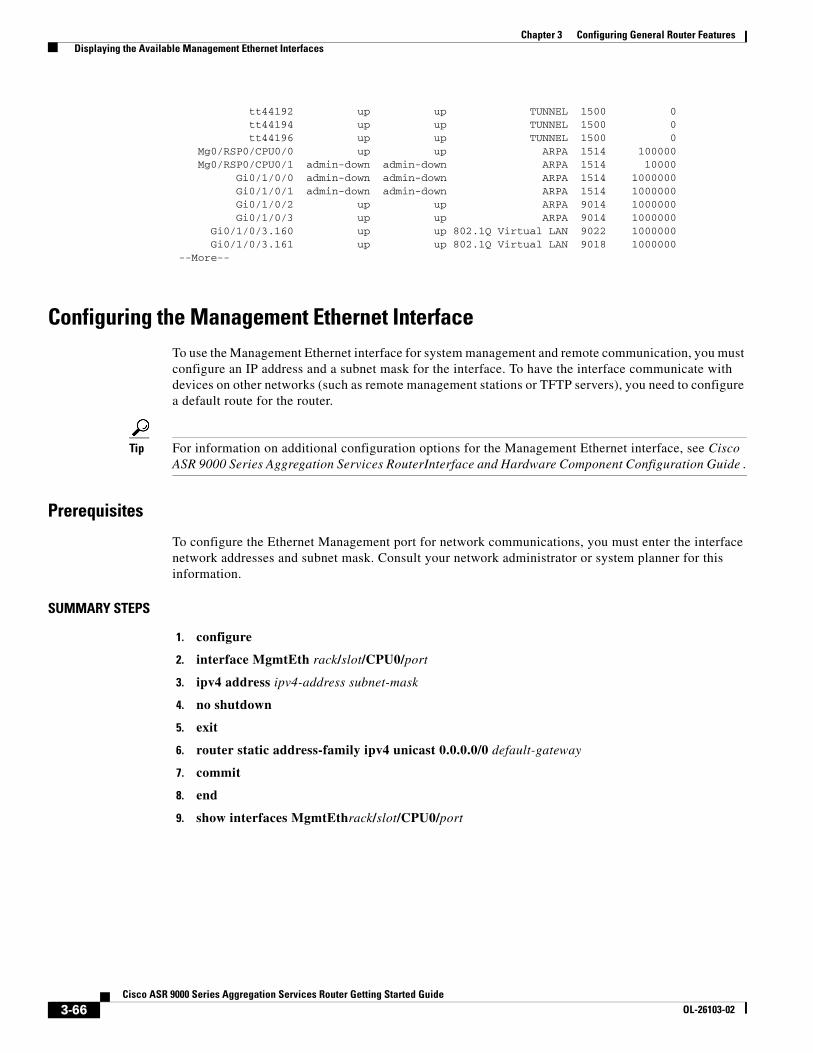
Chapter 3 Configuring General Router Features Displaying the Available Management Ethernet Interfaces
tt44192 up up TUNNEL 1500 0 tt44194 up up TUNNEL 1500 0 tt44196 up up TUNNEL 1500 0 Mg0/RSP0/CPU0/0 up up ARPA 1514 100000 Mg0/RSP0/CPU0/1 admin-down admin-down ARPA 1514 10000 Gi0/1/0/0 admin-down admin-down ARPA 1514 1000000 Gi0/1/0/1 admin-down admin-down ARPA 1514 1000000 Gi0/1/0/2 up up ARPA 9014 1000000 Gi0/1/0/3 up up ARPA 9014 1000000 Gi0/1/0/3.160 up up 802.1Q Virtual LAN 9022 1000000 Gi0/1/0/3.161 up up 802.1Q Virtual LAN 9018 1000000 --More--
Configuring the Management Ethernet InterfaceTo use the Management Ethernet interface for system management and remote communication, you must configure an IP address and a subnet mask for the interface. To have the interface communicate with devices on other networks (such as remote management stations or TFTP servers), you need to configure a default route for the router.
Tip For information on additional configuration options for the Management Ethernet interface, see Cisco ASR 9000 Series Aggregation Services RouterInterface and Hardware Component Configuration Guide .
Prerequisites
To configure the Ethernet Management port for network communications, you must enter the interface network addresses and subnet mask. Consult your network administrator or system planner for this information.
SUMMARY STEPS
1. configure
2. interface MgmtEth rack/slot/CPU0/port
3. ipv4 address ipv4-address subnet-mask
4. no shutdown
5. exit
6. router static address-family ipv4 unicast 0.0.0.0/0 default-gateway
7. commit
8. end
9. show interfaces MgmtEthrack/slot/CPU0/port
3-66Cisco ASR 9000 Series Aggregation Services Router Getting Started Guide
OL-26103-02
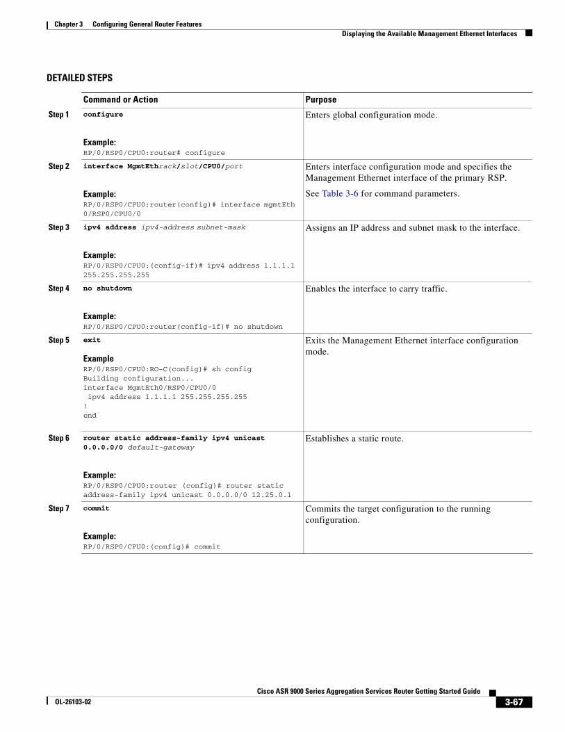
Chapter 3 Configuring General Router Features Displaying the Available Management Ethernet Interfaces
DETAILED STEPS
Command or Action Purpose
Step 1 configure
Example:RP/0/RSP0/CPU0:router# configure
Enters global configuration mode.
Step 2 interface MgmtEthrack/slot/CPU0/port
Example:RP/0/RSP0/CPU0:router(config)# interface mgmtEth 0/RSP0/CPU0/0
Enters interface configuration mode and specifies the Management Ethernet interface of the primary RSP.
See Table 3-6 for command parameters.
Step 3 ipv4 address ipv4-address subnet-mask
Example:RP/0/RSP0/CPU0:(config-if)# ipv4 address 1.1.1.1 255.255.255.255
Assigns an IP address and subnet mask to the interface.
Step 4 no shutdown
Example:RP/0/RSP0/CPU0:router(config-if)# no shutdown
Enables the interface to carry traffic.
Step 5 exit
ExampleRP/0/RSP0/CPU0:RO-C(config)# sh configBuilding configuration...interface MgmtEth0/RSP0/CPU0/0 ipv4 address 1.1.1.1 255.255.255.255!end
Exits the Management Ethernet interface configuration mode.
Step 6 router static address-family ipv4 unicast 0.0.0.0/0 default-gateway
Example:RP/0/RSP0/CPU0:router (config)# router static address-family ipv4 unicast 0.0.0.0/0 12.25.0.1
Establishes a static route.
Step 7 commit
Example:RP/0/RSP0/CPU0:(config)# commit
Commits the target configuration to the running configuration.
3-67Cisco ASR 9000 Series Aggregation Services Router Getting Started Guide
OL-26103-02
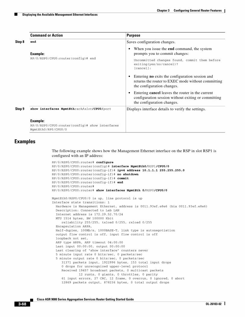
Chapter 3 Configuring General Router Features Displaying the Available Management Ethernet Interfaces
Examples
The following example shows how the Management Ethernet interface on the RSP in slot RSP1 is configured with an IP address:
RP/0/RSP0/CPU0:router# configureRP/0/RSP0/CPU0:router(config)# interface MgmtEth0/RSP1/CPU0/0RP/0/RSP0/CPU0:router(config-if)# ipv4 address 10.1.1.1 255.255.255.0RP/0/RSP0/CPU0:router(config-if)# no shutdownRP/0/RSP0/CPU0:router(config-if)# commitRP/0/RSP0/CPU0:router(config-if)# endRP/0/RSP0/CPU0:router#RP/0/RSP0/CPU0:router# show interfaces MgmtEth 0/RSP0/CPU0/0
MgmtEth0/RSP0/CPU0/0 is up, line protocol is up Interface state transitions: 1 Hardware is Management Ethernet, address is 0011.93ef.e8e6 (bia 0011.93ef.e8e6) Description: Connected to Lab LAN Internet address is 172.29.52.70/24 MTU 1514 bytes, BW 100000 Kbit reliability 255/255, txload 0/255, rxload 0/255 Encapsulation ARPA, Half-duplex, 100Mb/s, 1000BASE-T, link type is autonegotiation output flow control is off, input flow control is off loopback not set, ARP type ARPA, ARP timeout 04:00:00 Last input 00:00:00, output 00:00:00 Last clearing of "show interface" counters never 5 minute input rate 0 bits/sec, 0 packets/sec 5 minute output rate 0 bits/sec, 0 packets/sec 31371 packets input, 1922996 bytes, 153 total input drops 0 drops for unrecognized upper-level protocol Received 19457 broadcast packets, 0 multicast packets 12 runts, 0 giants, 0 throttles, 0 parity 61 input errors, 27 CRC, 12 frame, 0 overrun, 0 ignored, 0 abort 12869 packets output, 878236 bytes, 0 total output drops
Step 8 end
Example:RP/0/RSP0/CPU0:router(config)# end
Saves configuration changes.
• When you issue the end command, the system prompts you to commit changes:
Uncommitted changes found, commit them before exiting(yes/no/cancel)?[cancel]:
• Entering no exits the configuration session and returns the router to EXEC mode without committing the configuration changes.
• Entering cancel leaves the router in the current configuration session without exiting or committing the configuration changes.
Step 9 show interfaces MgmtEthrack/slot/CPU0/port
Example:RP/0/RSP0/CPU0:router(config)# show interfaces MgmtEth0/RP0/CPU0/0
Displays interface details to verify the settings.
Command or Action Purpose
3-68Cisco ASR 9000 Series Aggregation Services Router Getting Started Guide
OL-26103-02
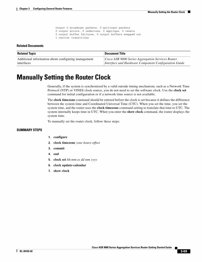
Chapter 3 Configuring General Router Features Manually Setting the Router Clock
Output 5 broadcast packets, 0 multicast packets 0 output errors, 0 underruns, 0 applique, 0 resets 0 output buffer failures, 0 output buffers swapped out 1 carrier transitions
Related Documents
Manually Setting the Router ClockGenerally, if the system is synchronized by a valid outside timing mechanism, such as a Network Time Protocol (NTP) or VINES clock source, you do not need to set the software clock. Use the clock set command for initial configuration or if a network time source is not available.
The clock timezone command should be entered before the clock is set because it defines the difference between the system time and Coordinated Universal Time (UTC). When you set the time, you set the system time, and the router uses the clock timezone command setting to translate that time to UTC. The system internally keeps time in UTC. When you enter the show clock command, the router displays the system time.
To manually set the router clock, follow these steps:
SUMMARY STEPS
1. configure
2. clock timezone zone hours-offset
3. commit
4. end
5. clock set hh:mm:ss dd mm yyyy
6. clock update-calendar
7. show clock
Related Topic Document Title
Additional information about configuring management interfaces
Cisco ASR 9000 Series Aggregation Services Router Interface and Hardware Component Configuration Guide
3-69Cisco ASR 9000 Series Aggregation Services Router Getting Started Guide
OL-26103-02
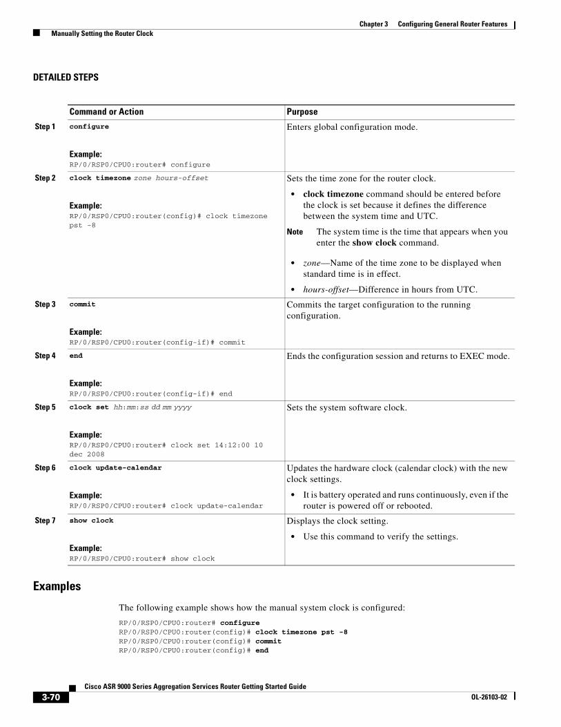
Chapter 3 Configuring General Router Features Manually Setting the Router Clock
DETAILED STEPS
Examples
The following example shows how the manual system clock is configured:
RP/0/RSP0/CPU0:router# configureRP/0/RSP0/CPU0:router(config)# clock timezone pst -8RP/0/RSP0/CPU0:router(config)# commitRP/0/RSP0/CPU0:router(config)# end
Command or Action Purpose
Step 1 configure
Example:RP/0/RSP0/CPU0:router# configure
Enters global configuration mode.
Step 2 clock timezone zone hours-offset
Example:RP/0/RSP0/CPU0:router(config)# clock timezone pst -8
Sets the time zone for the router clock.
• clock timezone command should be entered before the clock is set because it defines the difference between the system time and UTC.
Note The system time is the time that appears when you enter the show clock command.
• zone—Name of the time zone to be displayed when standard time is in effect.
• hours-offset—Difference in hours from UTC.
Step 3 commit
Example:RP/0/RSP0/CPU0:router(config-if)# commit
Commits the target configuration to the running configuration.
Step 4 end
Example:RP/0/RSP0/CPU0:router(config-if)# end
Ends the configuration session and returns to EXEC mode.
Step 5 clock set hh:mm:ss dd mm yyyy
Example:RP/0/RSP0/CPU0:router# clock set 14:12:00 10 dec 2008
Sets the system software clock.
Step 6 clock update-calendar
Example:RP/0/RSP0/CPU0:router# clock update-calendar
Updates the hardware clock (calendar clock) with the new clock settings.
• It is battery operated and runs continuously, even if the router is powered off or rebooted.
Step 7 show clock
Example:RP/0/RSP0/CPU0:router# show clock
Displays the clock setting.
• Use this command to verify the settings.
3-70Cisco ASR 9000 Series Aggregation Services Router Getting Started Guide
OL-26103-02
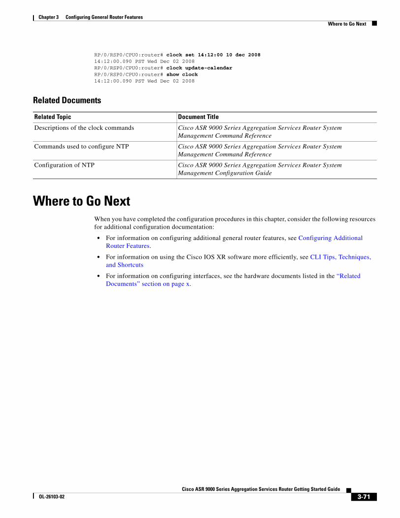
Chapter 3 Configuring General Router Features Where to Go Next
RP/0/RSP0/CPU0:router# clock set 14:12:00 10 dec 200814:12:00.090 PST Wed Dec 02 2008RP/0/RSP0/CPU0:router# clock update-calendarRP/0/RSP0/CPU0:router# show clock14:12:00.090 PST Wed Dec 02 2008
Related Documents
Where to Go NextWhen you have completed the configuration procedures in this chapter, consider the following resources for additional configuration documentation:
• For information on configuring additional general router features, see Configuring Additional Router Features.
• For information on using the Cisco IOS XR software more efficiently, see CLI Tips, Techniques, and Shortcuts
• For information on configuring interfaces, see the hardware documents listed in the “Related Documents” section on page x.
Related Topic Document Title
Descriptions of the clock commands Cisco ASR 9000 Series Aggregation Services Router System Management Command Reference
Commands used to configure NTP Cisco ASR 9000 Series Aggregation Services Router System Management Command Reference
Configuration of NTP Cisco ASR 9000 Series Aggregation Services Router System Management Configuration Guide
3-71Cisco ASR 9000 Series Aggregation Services Router Getting Started Guide
OL-26103-02

Chapter 3 Configuring General Router Features Where to Go Next
3-72Cisco ASR 9000 Series Aggregation Services Router Getting Started Guide
OL-26103-02