Embed Size (px)
Citation preview
Avaya Solution & Interoperability Test Lab
Configuring H.323 Signaling and IP Trunks between Avaya Communication Manager and Cisco CallManager 4.0 - Issue 1.0
Abstract
These Application Notes present a sample configuration for a network comprised of an Avaya S8700 Media Server IP Connect configuration and a Cisco CallManager. The focus is on the Avaya Communication Manager configuration for the H.323 Signaling Group and IP Trunk Group, and the corresponding configuration of the H.323 Gateway on the Cisco CallManager 4.0. The configuration described should be applicable to other Avaya Media Servers and Media Gateways.
SZ; Reviewed: GAK 4/8/2005
Solution & Interoperability Test Lab Application Notes ©2005 Avaya Inc. All Rights Reserved.
1 of 19 IP-trunk-CM.doc
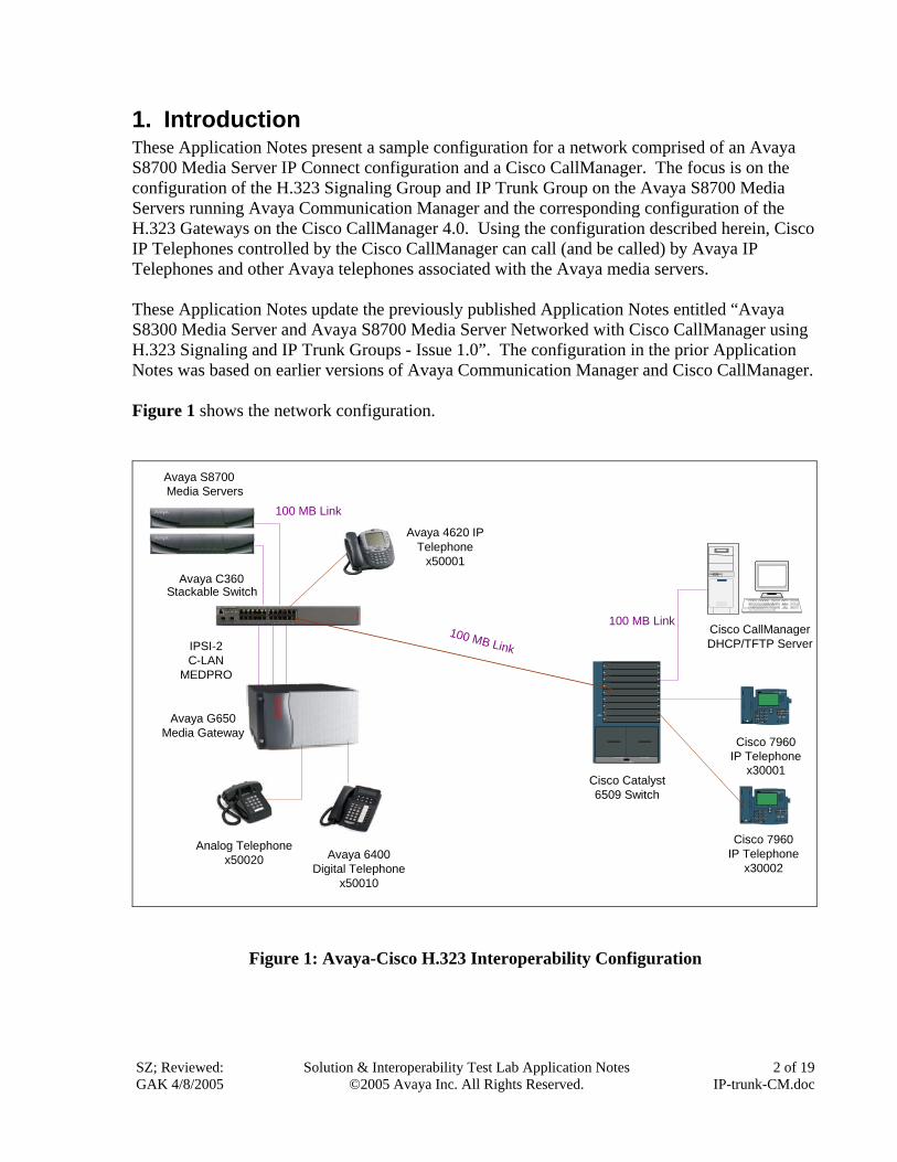
1. Introduction These Application Notes present a sample configuration for a network comprised of an Avaya S8700 Media Server IP Connect configuration and a Cisco CallManager. The focus is on the configuration of the H.323 Signaling Group and IP Trunk Group on the Avaya S8700 Media Servers running Avaya Communication Manager and the corresponding configuration of the H.323 Gateways on the Cisco CallManager 4.0. Using the configuration described herein, Cisco IP Telephones controlled by the Cisco CallManager can call (and be called) by Avaya IP Telephones and other Avaya telephones associated with the Avaya media servers. These Application Notes update the previously published Application Notes entitled “Avaya S8300 Media Server and Avaya S8700 Media Server Networked with Cisco CallManager using H.323 Signaling and IP Trunk Groups - Issue 1.0”. The configuration in the prior Application Notes was based on earlier versions of Avaya Communication Manager and Cisco CallManager. Figure 1 shows the network configuration.
Avaya S8700Media Servers
Cisco CallManagerDHCP/TFTP Server
Avaya C360Stackable Switch
100 MB Link
100 MB Link
Analog Telephonex50020
FANSTATUS
1
2
3
4
5
6
7
8
9
Power Supply 1 Power Supply 2
Catalyst 6500SERIES
1 2ABC
3DEF
4 5JKL
6MNOGHI
7 8TUV
9WXYZPQRS
* 0OPER
#
7960CISCO IP PHONE
imessagesdirectories
settingsservices
IPSI-2C-LAN
MEDPRO
Avaya G650Media Gateway
Cisco 7960IP Telephone
x30001Cisco Catalyst6509 Switch
1 2ABC
3DEF
4 5JKL
6MNOGHI
7 8TUV
9WXYZPQRS
* 0OPER
#
7960CISCO IP PHONE
imessagesdirectories
settingsservices
Cisco 7960IP Telephone
x30002
Avaya 4620 IPTelephone
x50001
100 MB Link
Avaya 6400Digital Telephone
x50010
Figure 1: Avaya-Cisco H.323 Interoperability Configuration
SZ; Reviewed: GAK 4/8/2005
Solution & Interoperability Test Lab Application Notes ©2005 Avaya Inc. All Rights Reserved.
2 of 19 IP-trunk-CM.doc
SZ; Reviewed: GAK 4/8/2005
Solution & Interoperability Test Lab Application Notes ©2005 Avaya Inc. All Rights Reserved.
3 of 19 IP-trunk-CM.doc
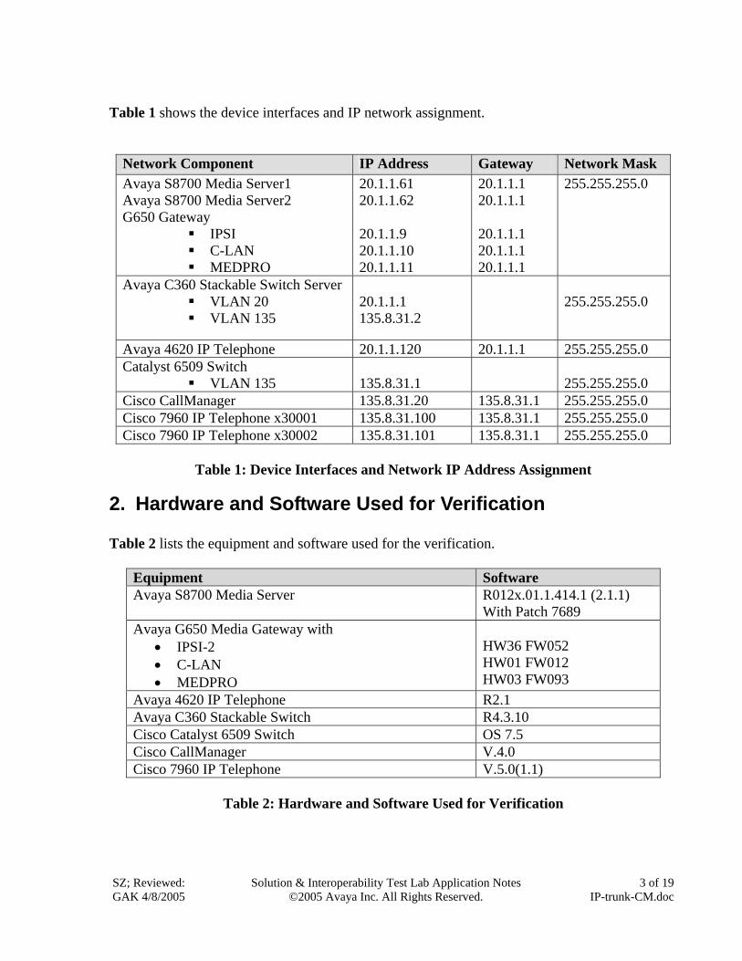
Table 1 shows the device interfaces and IP network assignment.
Network Component IP Address Gateway Network Mask Avaya S8700 Media Server1 Avaya S8700 Media Server2 G650 Gateway
IPSI C-LAN MEDPRO
20.1.1.61 20.1.1.62 20.1.1.9 20.1.1.10 20.1.1.11
20.1.1.1 20.1.1.1 20.1.1.1 20.1.1.1 20.1.1.1
255.255.255.0
Avaya C360 Stackable Switch Server VLAN 20 VLAN 135
20.1.1.1 135.8.31.2
255.255.255.0
Avaya 4620 IP Telephone 20.1.1.120 20.1.1.1 255.255.255.0 Catalyst 6509 Switch
VLAN 135 135.8.31.1
255.255.255.0
Cisco CallManager 135.8.31.20 135.8.31.1 255.255.255.0 Cisco 7960 IP Telephone x30001 135.8.31.100 135.8.31.1 255.255.255.0 Cisco 7960 IP Telephone x30002 135.8.31.101 135.8.31.1 255.255.255.0
Table 1: Device Interfaces and Network IP Address Assignment
2. Hardware and Software Used for Verification
Table 2 lists the equipment and software used for the verification.
Equipment Software Avaya S8700 Media Server R012x.01.1.414.1 (2.1.1)
With Patch 7689 Avaya G650 Media Gateway with
• IPSI-2 • C-LAN • MEDPRO
HW36 FW052 HW01 FW012 HW03 FW093
Avaya 4620 IP Telephone R2.1 Avaya C360 Stackable Switch R4.3.10 Cisco Catalyst 6509 Switch OS 7.5 Cisco CallManager V.4.0 Cisco 7960 IP Telephone V.5.0(1.1)
Table 2: Hardware and Software Used for Verification
SZ; Reviewed: GAK 4/8/2005
Solution & Interoperability Test Lab Application Notes ©2005 Avaya Inc. All Rights Reserved.
4 of 19 IP-trunk-CM.doc
3. Avaya S8700 Media Server Software Configuration This section presents configuration steps for the Avaya S8700 Media Server IP Connect Configuration. It is assumed that Avaya Communication Manager has been installed and the login and password credentials are available to the reader. The Avaya S8700 Media Server has multiple IP interfaces. Ethernet 1 is used for the control network to communicate with the IPSI circuit pack of the Avaya G650 Media Gateway. Ethernet 2 is dedicated to the services port. The services port uses the pre-configured IP address 192.11.13.6 with mask 255.255.255.252. Configure the computer’s IP address as 192.11.13.5 with mask 255.255.255.252. Connect the computer’s Ethernet interface to the services port with a crossover Ethernet cable. The Avaya Communication Manager SAT screens can be accessed using “telnet 192.11.13.6 5023” from a computer connected to the server’s services port.
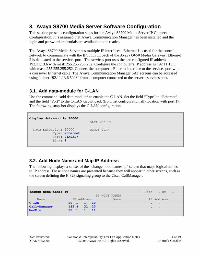
3.1. Add data-module for C-LAN Use the command “add data-module” to enable the C-LAN. Set the field “Type” to “Ethernet” and the field “Port” to the C-LAN circuit pack (from list configuration all) location with port 17. The following snapshot displays the C-LAN configuration. display data-module 20000 DATA MODULE Data Extension: 20000 Name: CLAN Type: ethernet Port: 01A0317 Link: 1
3.2. Add Node Name and Map IP Address The following displays a subset of the “change node-names ip” screen that maps logical names to IP address. These node names are presented because they will appear in other screens, such as the screen defining the H.323 signaling group to the Cisco CallManager. change node-names ip Page 1 of 1 IP NODE NAMES Name IP Address Name IP Address C-LAN 20 .1 .1 .10 . . . Call-Manager 135.8 .31 .20 . . . MedPro 20 .1 .1 .11 . . .
SZ; Reviewed: GAK 4/8/2005
Solution & Interoperability Test Lab Application Notes ©2005 Avaya Inc. All Rights Reserved.
5 of 19 IP-trunk-CM.doc
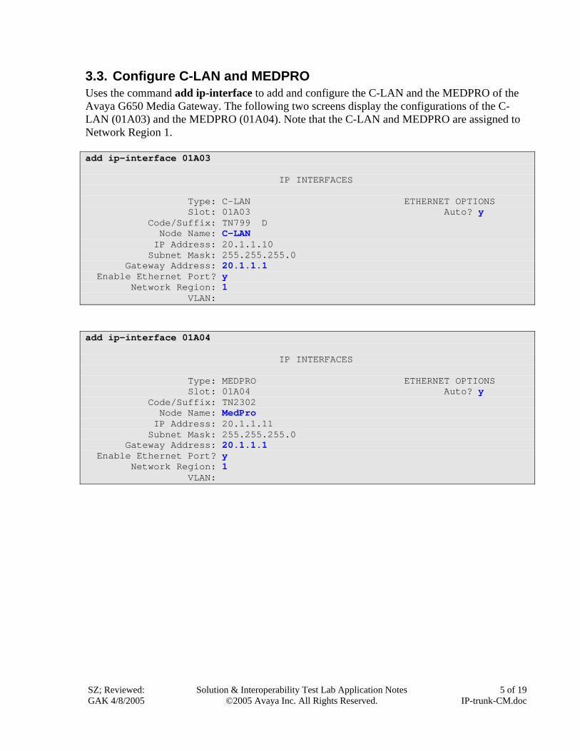
3.3. Configure C-LAN and MEDPRO Uses the command add ip-interface to add and configure the C-LAN and the MEDPRO of the Avaya G650 Media Gateway. The following two screens display the configurations of the C-LAN (01A03) and the MEDPRO (01A04). Note that the C-LAN and MEDPRO are assigned to Network Region 1. add ip-interface 01A03 IP INTERFACES Type: C-LAN ETHERNET OPTIONS Slot: 01A03 Auto? y Code/Suffix: TN799 D Node Name: C-LAN IP Address: 20.1.1.10 Subnet Mask: 255.255.255.0 Gateway Address: 20.1.1.1 Enable Ethernet Port? y Network Region: 1 VLAN:
add ip-interface 01A04 IP INTERFACES Type: MEDPRO ETHERNET OPTIONS Slot: 01A04 Auto? y Code/Suffix: TN2302 Node Name: MedPro IP Address: 20.1.1.11 Subnet Mask: 255.255.255.0 Gateway Address: 20.1.1.1 Enable Ethernet Port? y Network Region: 1 VLAN:
SZ; Reviewed: GAK 4/8/2005
Solution & Interoperability Test Lab Application Notes ©2005 Avaya Inc. All Rights Reserved.
6 of 19 IP-trunk-CM.doc
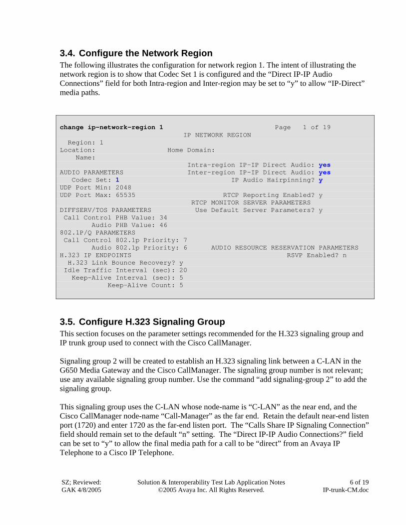
3.4. Configure the Network Region The following illustrates the configuration for network region 1. The intent of illustrating the network region is to show that Codec Set 1 is configured and the “Direct IP-IP Audio Connections” field for both Intra-region and Inter-region may be set to “y” to allow “IP-Direct” media paths. change ip-network-region 1 Page 1 of 19 IP NETWORK REGION Region: 1 Location: Home Domain: Name: Intra-region IP-IP Direct Audio: yes AUDIO PARAMETERS Inter-region IP-IP Direct Audio: yes Codec Set: 1 IP Audio Hairpinning? y UDP Port Min: 2048 UDP Port Max: 65535 RTCP Reporting Enabled? y RTCP MONITOR SERVER PARAMETERS DIFFSERV/TOS PARAMETERS Use Default Server Parameters? y Call Control PHB Value: 34 Audio PHB Value: 46 802.1P/Q PARAMETERS Call Control 802.1p Priority: 7 Audio 802.1p Priority: 6 AUDIO RESOURCE RESERVATION PARAMETERS H.323 IP ENDPOINTS RSVP Enabled? n H.323 Link Bounce Recovery? y Idle Traffic Interval (sec): 20 Keep-Alive Interval (sec): 5 Keep-Alive Count: 5
3.5. Configure H.323 Signaling Group This section focuses on the parameter settings recommended for the H.323 signaling group and IP trunk group used to connect with the Cisco CallManager. Signaling group 2 will be created to establish an H.323 signaling link between a C-LAN in the G650 Media Gateway and the Cisco CallManager. The signaling group number is not relevant; use any available signaling group number. Use the command “add signaling-group 2” to add the signaling group. This signaling group uses the C-LAN whose node-name is “C-LAN” as the near end, and the Cisco CallManager node-name “Call-Manager” as the far end. Retain the default near-end listen port (1720) and enter 1720 as the far-end listen port. The “Calls Share IP Signaling Connection” field should remain set to the default “n” setting. The “Direct IP-IP Audio Connections?” field can be set to “y” to allow the final media path for a call to be “direct” from an Avaya IP Telephone to a Cisco IP Telephone.
SZ; Reviewed: GAK 4/8/2005
Solution & Interoperability Test Lab Application Notes ©2005 Avaya Inc. All Rights Reserved.
7 of 19 IP-trunk-CM.doc
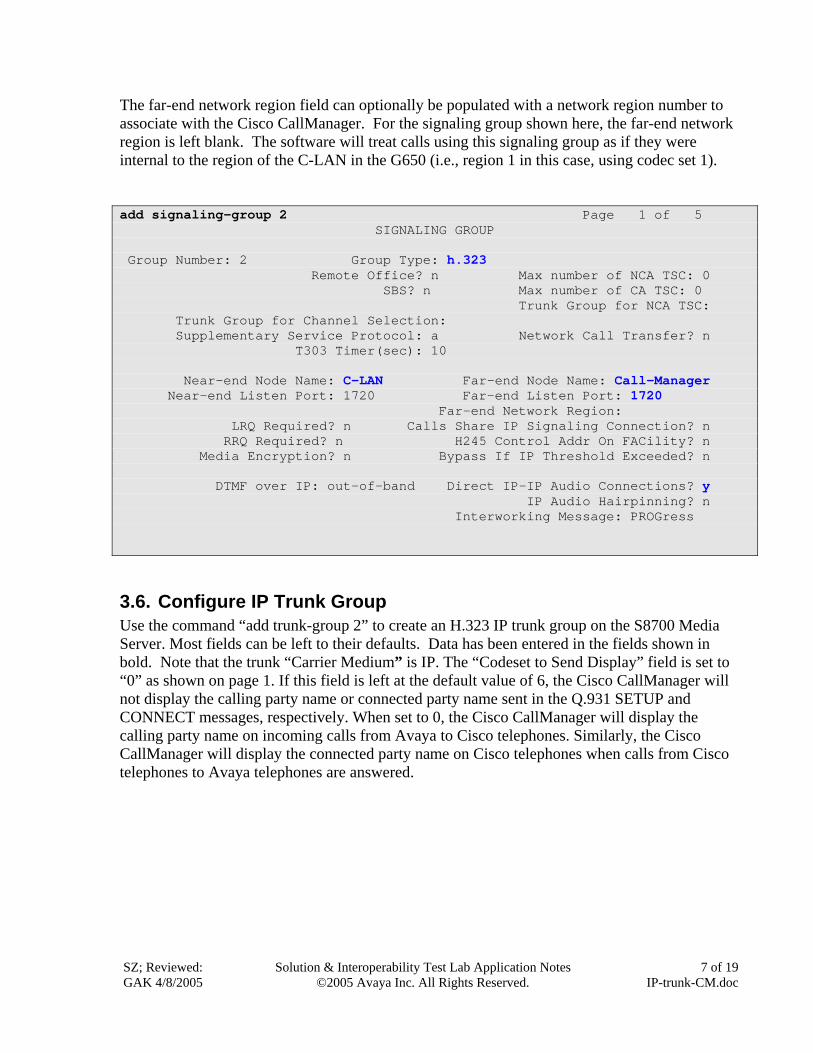
The far-end network region field can optionally be populated with a network region number to associate with the Cisco CallManager. For the signaling group shown here, the far-end network region is left blank. The software will treat calls using this signaling group as if they were internal to the region of the C-LAN in the G650 (i.e., region 1 in this case, using codec set 1). add signaling-group 2 Page 1 of 5 SIGNALING GROUP Group Number: 2 Group Type: h.323 Remote Office? n Max number of NCA TSC: 0 SBS? n Max number of CA TSC: 0 Trunk Group for NCA TSC: Trunk Group for Channel Selection: Supplementary Service Protocol: a Network Call Transfer? n T303 Timer(sec): 10 Near-end Node Name: C-LAN Far-end Node Name: Call-Manager Near-end Listen Port: 1720 Far-end Listen Port: 1720 Far-end Network Region: LRQ Required? n Calls Share IP Signaling Connection? n RRQ Required? n H245 Control Addr On FACility? n Media Encryption? n Bypass If IP Threshold Exceeded? n DTMF over IP: out-of-band Direct IP-IP Audio Connections? y IP Audio Hairpinning? n Interworking Message: PROGress
3.6. Configure IP Trunk Group Use the command “add trunk-group 2” to create an H.323 IP trunk group on the S8700 Media Server. Most fields can be left to their defaults. Data has been entered in the fields shown in bold. Note that the trunk “Carrier Medium” is IP. The “Codeset to Send Display” field is set to “0” as shown on page 1. If this field is left at the default value of 6, the Cisco CallManager will not display the calling party name or connected party name sent in the Q.931 SETUP and CONNECT messages, respectively. When set to 0, the Cisco CallManager will display the calling party name on incoming calls from Avaya to Cisco telephones. Similarly, the Cisco CallManager will display the connected party name on Cisco telephones when calls from Cisco telephones to Avaya telephones are answered.
SZ; Reviewed: GAK 4/8/2005
Solution & Interoperability Test Lab Application Notes ©2005 Avaya Inc. All Rights Reserved.
8 of 19 IP-trunk-CM.doc
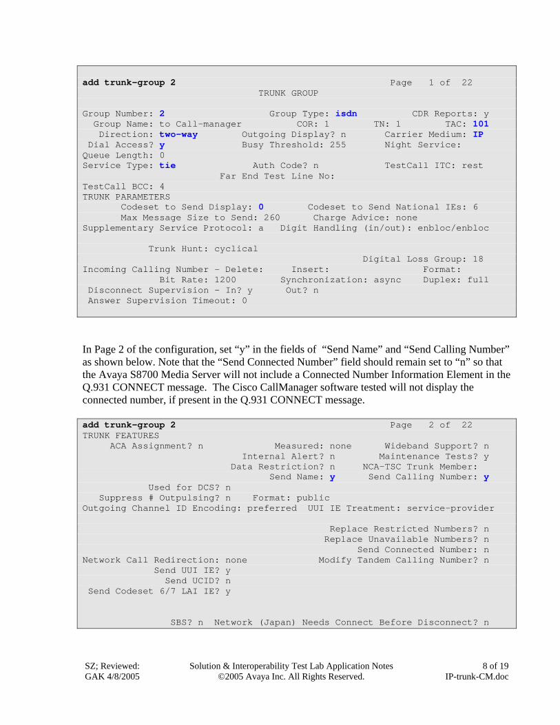
add trunk-group 2 Page 1 of 22 TRUNK GROUP Group Number: 2 Group Type: isdn CDR Reports: y Group Name: to Call-manager COR: 1 TN: 1 TAC: 101 Direction: two-way Outgoing Display? n Carrier Medium: IP Dial Access? y Busy Threshold: 255 Night Service: Queue Length: 0 Service Type: tie Auth Code? n TestCall ITC: rest Far End Test Line No: TestCall BCC: 4 TRUNK PARAMETERS Codeset to Send Display: 0 Codeset to Send National IEs: 6 Max Message Size to Send: 260 Charge Advice: none Supplementary Service Protocol: a Digit Handling (in/out): enbloc/enbloc Trunk Hunt: cyclical Digital Loss Group: 18 Incoming Calling Number - Delete: Insert: Format: Bit Rate: 1200 Synchronization: async Duplex: full Disconnect Supervision - In? y Out? n Answer Supervision Timeout: 0
In Page 2 of the configuration, set “y” in the fields of “Send Name” and “Send Calling Number” as shown below. Note that the “Send Connected Number” field should remain set to “n” so that the Avaya S8700 Media Server will not include a Connected Number Information Element in the Q.931 CONNECT message. The Cisco CallManager software tested will not display the connected number, if present in the Q.931 CONNECT message. add trunk-group 2 Page 2 of 22 TRUNK FEATURES ACA Assignment? n Measured: none Wideband Support? n Internal Alert? n Maintenance Tests? y Data Restriction? n NCA-TSC Trunk Member: Send Name: y Send Calling Number: y Used for DCS? n Suppress # Outpulsing? n Format: public Outgoing Channel ID Encoding: preferred UUI IE Treatment: service-provider Replace Restricted Numbers? n Replace Unavailable Numbers? n Send Connected Number: n Network Call Redirection: none Modify Tandem Calling Number? n Send UUI IE? y Send UCID? n Send Codeset 6/7 LAI IE? y SBS? n Network (Japan) Needs Connect Before Disconnect? n
SZ; Reviewed: GAK 4/8/2005
Solution & Interoperability Test Lab Application Notes ©2005 Avaya Inc. All Rights Reserved.
9 of 19 IP-trunk-CM.doc
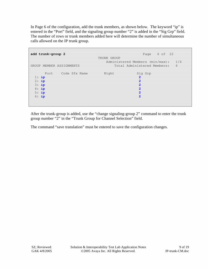
In Page 6 of the configuration, add the trunk members, as shown below. The keyword “ip” is entered in the “Port” field, and the signaling group number “2” is added in the “Sig Grp” field. The number of rows or trunk members added here will determine the number of simultaneous calls allowed on the IP trunk group. add trunk-group 2 Page 6 of 22 TRUNK GROUP Administered Members (min/max): 1/6 GROUP MEMBER ASSIGNMENTS Total Administered Members: 6 Port Code Sfx Name Night Sig Grp 1: ip 2 2: ip 2 3: ip 2 4: ip 2 5: ip 2 6: ip 2
After the trunk-group is added, use the “change signaling-group 2” command to enter the trunk group number “2” in the “Trunk Group for Channel Selection” field. The command “save translation” must be entered to save the configuration changes.
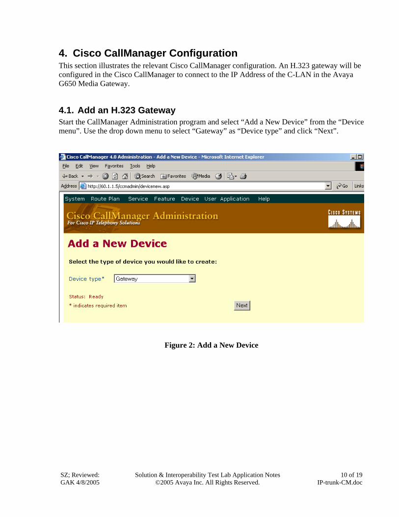
4. Cisco CallManager Configuration This section illustrates the relevant Cisco CallManager configuration. An H.323 gateway will be configured in the Cisco CallManager to connect to the IP Address of the C-LAN in the Avaya G650 Media Gateway.
4.1. Add an H.323 Gateway Start the CallManager Administration program and select “Add a New Device” from the “Device menu”. Use the drop down menu to select “Gateway” as “Device type” and click “Next”.
Figure 2: Add a New Device
SZ; Reviewed: GAK 4/8/2005
Solution & Interoperability Test Lab Application Notes ©2005 Avaya Inc. All Rights Reserved.
10 of 19 IP-trunk-CM.doc
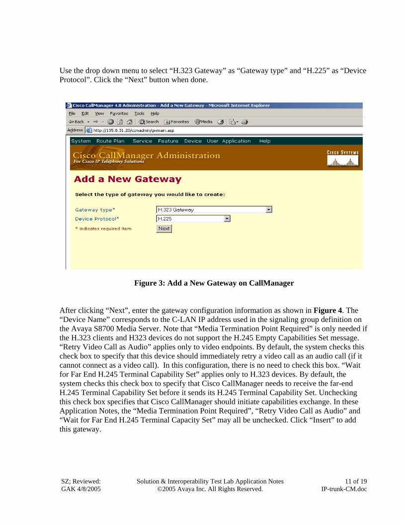
Use the drop down menu to select “H.323 Gateway” as “Gateway type” and “H.225” as “Device Protocol”. Click the “Next” button when done.
Figure 3: Add a New Gateway on CallManager After clicking “Next”, enter the gateway configuration information as shown in Figure 4. The “Device Name” corresponds to the C-LAN IP address used in the signaling group definition on the Avaya S8700 Media Server. Note that “Media Termination Point Required” is only needed if the H.323 clients and H323 devices do not support the H.245 Empty Capabilities Set message. “Retry Video Call as Audio” applies only to video endpoints. By default, the system checks this check box to specify that this device should immediately retry a video call as an audio call (if it cannot connect as a video call). In this configuration, there is no need to check this box. “Wait for Far End H.245 Terminal Capability Set” applies only to H.323 devices. By default, the system checks this check box to specify that Cisco CallManager needs to receive the far-end H.245 Terminal Capability Set before it sends its H.245 Terminal Capability Set. Unchecking this check box specifies that Cisco CallManager should initiate capabilities exchange. In these Application Notes, the “Media Termination Point Required”, “Retry Video Call as Audio” and “Wait for Far End H.245 Terminal Capacity Set” may all be unchecked. Click “Insert” to add this gateway.
SZ; Reviewed: GAK 4/8/2005
Solution & Interoperability Test Lab Application Notes ©2005 Avaya Inc. All Rights Reserved.
11 of 19 IP-trunk-CM.doc
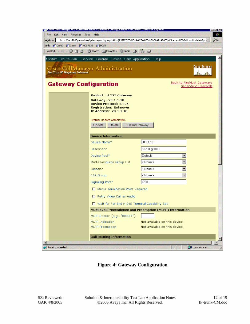
Figure 4: Gateway Configuration
SZ; Reviewed: GAK 4/8/2005
Solution & Interoperability Test Lab Application Notes ©2005 Avaya Inc. All Rights Reserved.
12 of 19 IP-trunk-CM.doc
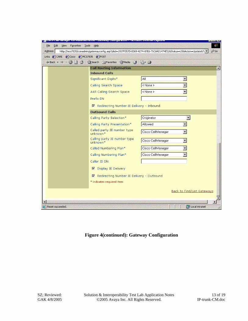
Figure 4(continued): Gateway Configuration
SZ; Reviewed: GAK 4/8/2005
Solution & Interoperability Test Lab Application Notes ©2005 Avaya Inc. All Rights Reserved.
13 of 19 IP-trunk-CM.doc
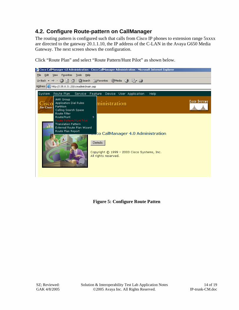
4.2. Configure Route-pattern on CallManager The routing pattern is configured such that calls from Cisco IP phones to extension range 5xxxx are directed to the gateway 20.1.1.10, the IP address of the C-LAN in the Avaya G650 Media Gateway. The next screen shows the configuration. Click “Route Plan” and select “Route Pattern/Hunt Pilot” as shown below.
Figure 5: Configure Route Patten
SZ; Reviewed: GAK 4/8/2005
Solution & Interoperability Test Lab Application Notes ©2005 Avaya Inc. All Rights Reserved.
14 of 19 IP-trunk-CM.doc
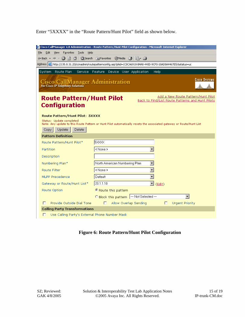
Enter “5XXXX” in the “Route Pattern/Hunt Pilot” field as shown below.
Figure 6: Route Pattern/Hunt Pilot Configuration
SZ; Reviewed: GAK 4/8/2005
Solution & Interoperability Test Lab Application Notes ©2005 Avaya Inc. All Rights Reserved.
15 of 19 IP-trunk-CM.doc
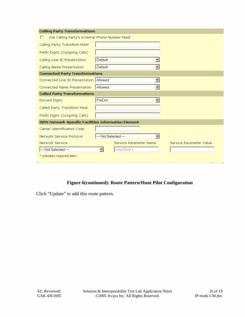
Figure 6(continued): Route Pattern/Hunt Pilot Configuration
Click “Update” to add this route pattern.
SZ; Reviewed: GAK 4/8/2005
Solution & Interoperability Test Lab Application Notes ©2005 Avaya Inc. All Rights Reserved.
16 of 19 IP-trunk-CM.doc
SZ; Reviewed: GAK 4/8/2005
Solution & Interoperability Test Lab Application Notes ©2005 Avaya Inc. All Rights Reserved.
17 of 19 IP-trunk-CM.doc
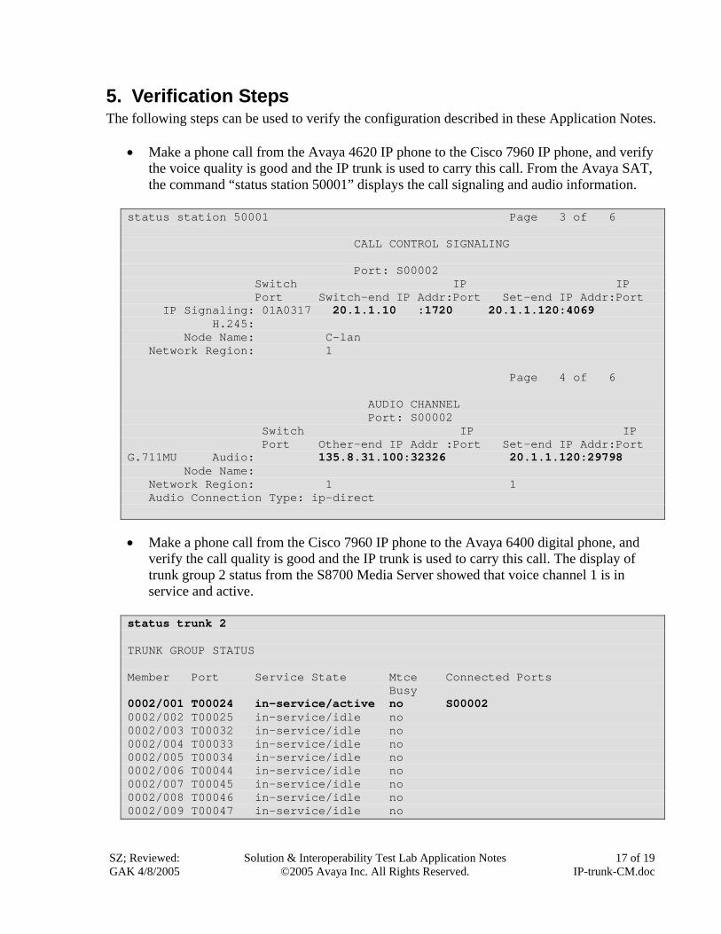
5. Verification Steps The following steps can be used to verify the configuration described in these Application Notes.
• Make a phone call from the Avaya 4620 IP phone to the Cisco 7960 IP phone, and verify
the voice quality is good and the IP trunk is used to carry this call. From the Avaya SAT, the command “status station 50001” displays the call signaling and audio information.
status station 50001 Page 3 of 6 CALL CONTROL SIGNALING Port: S00002 Switch IP IP Port Switch-end IP Addr:Port Set-end IP Addr:Port IP Signaling: 01A0317 20.1.1.10 :1720 20.1.1.120:4069 H.245: Node Name: C-lan Network Region: 1 Page 4 of 6 AUDIO CHANNEL Port: S00002 Switch IP IP Port Other-end IP Addr :Port Set-end IP Addr:Port G.711MU Audio: 135.8.31.100:32326 20.1.1.120:29798 Node Name: Network Region: 1 1 Audio Connection Type: ip-direct
• Make a phone call from the Cisco 7960 IP phone to the Avaya 6400 digital phone, and verify the call quality is good and the IP trunk is used to carry this call. The display of trunk group 2 status from the S8700 Media Server showed that voice channel 1 is in service and active.
status trunk 2 TRUNK GROUP STATUS Member Port Service State Mtce Connected Ports Busy 0002/001 T00024 in-service/active no S00002 0002/002 T00025 in-service/idle no 0002/003 T00032 in-service/idle no 0002/004 T00033 in-service/idle no 0002/005 T00034 in-service/idle no 0002/006 T00044 in-service/idle no 0002/007 T00045 in-service/idle no 0002/008 T00046 in-service/idle no 0002/009 T00047 in-service/idle no
SZ; Reviewed: GAK 4/8/2005
Solution & Interoperability Test Lab Application Notes ©2005 Avaya Inc. All Rights Reserved.
18 of 19 IP-trunk-CM.doc
• Make a phone call from the Cisco 7960 IP phone to the Avaya analog phone, and verify the voice quality is good.
• Display verifications:
o For calls from an Avaya telephone to a Cisco IP telephone, the Cisco IP telephone will display the name and number of the Avaya caller, provided the Avaya server is provisioned to send the calling party name and number. When the Cisco telephone is answered, the Avaya telephone will display the number and the name of the connected party, when sent by the Cisco CallManager.
o For calls from a Cisco telephone to an Avaya telephone, the Avaya telephone will display the calling party name and number, when sent by the Cisco CallManager. When the Avaya telephone is answered, the Cisco telephone will display the name of the connected party sent by the Avaya Media Server, and the dialed number (i.e., which may be different from the connected number. These Application Notes recommend that the Avaya Media Servers be provisioned to refrain from sending the Connected Number. Cisco CallManager would not display the Connected Number, if sent by Avaya).
6. Conclusion As illustrated in these Application Notes, the Avaya S8700 Media Server and Avaya G650 Media Gateway can interoperate with Cisco CallManager using an H.323 IP trunk. Final media paths for calls can be “ip-direct” between Cisco IP telephones and Avaya IP Telephones. The calling party name and number can be displayed for calls in both directions.
SZ; Reviewed: GAK 4/8/2005
Solution & Interoperability Test Lab Application Notes ©2005 Avaya Inc. All Rights Reserved.
19 of 19 IP-trunk-CM.doc
©2005 Avaya Inc. All Rights Reserved. Avaya and the Avaya Logo are trademarks of Avaya Inc. All trademarks identified by ® and ™ are registered trademarks or trademarks, respectively, of Avaya Inc. All other trademarks are the property of their respective owners. The information provided in these Application Notes is subject to change without notice. The configurations, technical data, and recommendations provided in these Application Notes are believed to be accurate and dependable, but are presented without express or implied warranty. Users are responsible for their application of any products specified in these Application Notes. Please e-mail any questions or comments pertaining to these Application Notes along with the full title name and filename, located in the lower right corner, directly to the Avaya Solution & Interoperability Test Lab at [email protected]