Embed Size (px)
Citation preview
OL-21524-01
C H A P T E R 12
Configuring Radio Resource ManagementOverview of Radio Resource ManagementThe radio resource management (RRM) software embedded in the controller acts as a built-in RF engineer to consistently provide real-time RF management of your wireless network. RRM enables controllers to continually monitor their associated lightweight access points for the following information:
• Traffic load—The total bandwidth used for transmitting and receiving traffic. It enables wireless LAN managers to track and plan network growth ahead of client demand.
• Interference—The amount of traffic coming from other 802.11 sources.
• Noise—The amount of non-802.11 traffic that is interfering with the currently assigned channel.
• Coverage—The received signal strength (RSSI) and signal-to-noise ratio (SNR) for all connected clients.
• Other —The number of nearby access points.
Using this information, RRM can periodically reconfigure the 802.11 RF network for best efficiency. To do this, RRM performs these functions:
• Radio resource monitoring
• Transmit power control
• Dynamic channel assignment
• Coverage hole detection and correction
Radio Resource MonitoringRRM automatically detects and configures new controllers and lightweight access points as they are added to the network. It then automatically adjusts associated and nearby lightweight access points to optimize coverage and capacity.
Lightweight access points can simultaneously scan all valid 802.11a/b/g channels for the country of operation as well as for channels available in other locations. The access points go “off-channel” for a period not greater than 60 ms to monitor these channels for noise and interference. Packets collected during this time are analyzed to detect rogue access points, rogue clients, ad-hoc clients, and interfering access points.
Note In the presence of voice traffic (in the last 100 ms), the access points defer off-channel measurements.
12-1Cisco Wireless LAN Controller Configuration Guide
Chapter 12 Configuring Radio Resource ManagementOverview of Radio Resource Management
Each access point spends only 0.2 percent of its time off-channel. This activity is distributed across all access points so that adjacent access points are not scanning at the same time, which could adversely affect wireless LAN performance.
Transmit Power ControlThe controller dynamically controls access point transmit power based on real-time wireless LAN conditions. Typically, power can be kept low to gain extra capacity and reduce interference. The controller attempts to balance the access points’ transmit power according to how the access points are seen by their third strongest neighbor.
The transmit power control (TPC) algorithm both increases and decreases an access point’s power in response to changes in the RF environment. In most instances, TPC seeks to lower an access point's power to reduce interference, but in the case of a sudden change in the RF coverage—for example, if an access point fails or becomes disabled—TPC can also increase power on surrounding access points. This feature is different from coverage hole detection, which is primarily concerned with clients. TPC provides enough RF power to achieve desired coverage levels while avoiding channel interference between access points.
Note See Step 7 on page 12-33 for an explanation of the transmit power levels.
Dynamic Channel AssignmentTwo adjacent access points on the same channel can cause either signal contention or signal collision. In a collision, data is not received by the access point. This functionality can become a problem, for example, when someone reading e-mail in a café affects the performance of the access point in a neighboring business. Even though these are completely separate networks, someone sending traffic to the café on channel 1 can disrupt communication in an enterprise using the same channel. Controllers can dynamically allocate access point channel assignments to avoid conflict and to increase capacity and performance. Channels are “reused” to avoid wasting scarce RF resources. In other words, channel 1 is allocated to a different access point far from the café, which is more effective than not using channel 1 altogether.
The controller’s dynamic channel assignment (DCA) capabilities are also useful in minimizing adjacent channel interference between access points. For example, two overlapping channels in the 802.11b/g band, such as 1 and 2, cannot both simultaneously use 11/54 Mbps. By effectively reassigning channels, the controller keeps adjacent channels separated.
The controller examines a variety of real-time RF characteristics to efficiently handle channel assignments as follows:
• Access point received energy—The received signal strength measured between each access point and its nearby neighboring access points. Channels are optimized for the highest network capacity.
• Noise—Noise can limit signal quality at the client and access point. An increase in noise reduces the effective cell size and degrades user experience. By optimizing channels to avoid noise sources, the controller can optimize coverage while maintaining system capacity. If a channel is unusable due to excessive noise, that channel can be avoided.
• 802.11 Interference—Interference is any 802.11 traffic that is not part of your wireless LAN, including rogue access points and neighboring wireless networks. Lightweight access points constantly scan all channels looking for sources of interference. If the amount of 802.11 interference exceeds a predefined configurable threshold (the default is 10 percent), the access point sends an
12-2Cisco Wireless LAN Controller Configuration Guide
OL-21524-01
Chapter 12 Configuring Radio Resource ManagementOverview of Radio Resource Management
alert to the controller. Using the RRM algorithms, the controller may then dynamically rearrange channel assignments to increase system performance in the presence of the interference. Such an adjustment could result in adjacent lightweight access points being on the same channel, but this setup is preferable to having the access points remain on a channel that is unusable due to an interfering foreign access point.
In addition, if other wireless networks are present, the controller shifts the usage of channels to complement the other networks. For example, if one network is on channel 6, an adjacent wireless LAN is assigned to channel 1 or 11. This arrangement increases the capacity of the network by limiting the sharing of frequencies. If a channel has virtually no capacity remaining, the controller may choose to avoid this channel. In very dense deployments in which all nonoverlapping channels are occupied, the controller does its best, but you must consider RF density when setting expectations.
• Utilization—When utilization monitoring is enabled, capacity calculations can consider that some access points are deployed in ways that carry more traffic than other access points (for example, a lobby versus an engineering area). The controller can then assign channels to improve the access point with the worst performance reported.
• Load—The load is taken into account when changing the channel structure to minimize the impact on clients currently in the wireless LAN. This metric keeps track of every access point’s transmitted and received packet counts to determine how busy the access points are. New clients avoid an overloaded access point and associate to a new access point. This parameter is disabled by default.
The controller combines this RF characteristic information with RRM algorithms to make system-wide decisions. Conflicting demands are resolved using soft-decision metrics that guarantee the best choice for minimizing network interference. The end result is optimal channel configuration in a three-dimensional space, where access points on the floor above and below play a major factor in an overall wireless LAN configuration.
In controller software releases prior to 5.1, only radios using 20-MHz channels are supported by DCA. In controller software release 5.1 or later releases, DCA is extended to support 802.11n 40-MHz channels in the 5-GHz band. 40-MHz channelization allows radios to achieve higher instantaneous data rates (potentially 2.25 times higher than 20-MHz channels). In controller software release 5.1 or later releases, you can choose if DCA works at 20 or 40 MHz.
Note Radios using 40-MHz channels in the 2.4-GHz band are not supported by DCA.
The RRM startup mode is invoked in the following conditions:
• In a single-controller environment, the RRM startup mode is invoked after the controller is rebooted.
• In a multiple-controller environment, the RRM startup mode is invoked after an RF Group leader is elected.
RRM startup mode runs for 100 minutes (10 iterations at 10-minute intervals). The duration of the RRM startup mode is independent of the DCA interval, sensitivity, and network size. The startup mode consists of 10 DCA runs with high sensitivity (making channel changes easy and sensitive to the environment) to converge to a steady state channel plan. After the startup mode is finished, DCA continues to run at the specified interval and sensitivity.
12-3Cisco Wireless LAN Controller Configuration Guide
OL-21524-01
Chapter 12 Configuring Radio Resource ManagementOverview of RF Groups
Coverage Hole Detection and CorrectionThe RRM coverage hole detection algorithm can detect areas of radio coverage in a wireless LAN that are below the level needed for robust radio performance. This feature can alert you to the need for an additional (or relocated) lightweight access point.
If clients on a lightweight access point are detected at threshold levels (RSSI, failed client count, percentage of failed packets, and number of failed packets) lower than those specified in the RRM configuration, the access point sends a “coverage hole” alert to the controller. The alert indicates the existence of an area where clients are continually experiencing poor signal coverage, without having a viable access point to which to roam. The controller discriminates between coverage holes that can and cannot be corrected. For coverage holes that can be corrected, the controller mitigates the coverage hole by increasing the transmit power level for that specific access point. The controller does not mitigate coverage holes caused by clients that are unable to increase their transmit power or are statically set to a power level because increasing their downstream transmit power might increase interference in the network.
Note While transmit power control and DCA can operate in multiple-controller environments (based on RF domains), coverage hole detection is performed on a per-controller basis. In controller software release 5.2 or later releases, you can disable coverage hole detection on a per-WLAN basis. See the “Disabling Coverage Hole Detection per WLAN” section on page 7-64 for more information.
RRM BenefitsRRM produces a network with optimal capacity, performance, and reliability. It frees you from having to continually monitor the network for noise and interference problems, which can be transient and difficult to troubleshoot. RRM ensures that clients enjoy a seamless, trouble-free connection throughout the Cisco unified wireless network.
RRM uses separate monitoring and control for each deployed network: 802.11a and 802.11b/g. The RRM algorithms run separately for each radio type (802.11a and 802.11b/g). RRM uses both measurements and algorithms. RRM measurements can be adjusted using monitor intervals, but they cannot be disabled. RRM algorithms are enabled automatically but can be disabled by statically configuring channel and power assignment. The RRM algorithms run at a specified updated interval, which is 600 seconds by default.
Overview of RF GroupsAn RF group, also known as an RF domain, is a cluster of controllers that coordinates its RRM calculations on a per 802.11-network basis. An RF group exists for each 802.11 network type. Clustering controllers into RF groups enables the RRM algorithms to scale beyond a single controller.
Lightweight access points periodically send out neighbor messages over the air. Access points using the the same RF group name are able to validate messages from each other. When access points on different controllers hear validated neighbor messages at a signal strength of –80 dBm or stronger, the controllers dynamically form an RF group.
12-4Cisco Wireless LAN Controller Configuration Guide
OL-21524-01
Chapter 12 Configuring Radio Resource ManagementOverview of RF Groups
Note RF groups and mobility groups are similar in that they both define clusters of controllers, but they are different in terms of their use. An RF group facilitates scalable, system-wide dynamic RF management while a mobility group facilitates scalable, system-wide mobility and controller redundancy. See Chapter 13, “Configuring Cisco CleanAir,” for more information on mobility groups.
Controller software release 4.2.99.0 or later releases support up to 20 controllers and 1000 access points in an RF group. For example, a Cisco WiSM controller supports up to 150 access points, so you can have up to 6 WiSM controllers in an RF group (150 access points x 6 controllers = 900 access points, which is less than 1000). Similarly, a 4404 controller supports up to 100 access points, so you can have up to 10 4404 controllers in an RF group (100 x 10 = 1000). The Cisco 2100 Series Controller supports a maximum of 25 access points, so you can have up to 20 of these controllers in an RF group.
Note In controller software release 4.2.61.0 or earlier releases, RRM supports no more than five Cisco 4400 Series Controllers in an RF group.
RF Group LeaderThe members of an RF group elect an RF group leader to maintain a “master” power and channel scheme for the group. The RF grouping algorithm dynamically chooses the RF group leader and ensures that an RF group leader is always present. Group leader assignments can and do change (for instance, if the current RF group leader becomes inoperable or if RF group members experience major changes).
The RF group leader analyzes real-time radio data collected by the system, calculates the power and channel assignments, and sends them to each of the controllers in the RF group. The RRM algorithms ensure system-wide stability and restrain channel and power scheme changes to the appropriate local RF neighborhoods.
In controller software releases prior to 6.0, the dynamic channel assignment (DCA) search algorithm attempts to find a good channel plan for the radios associated to controllers in the RF group, but it does not adopt a new channel plan unless it is considerably better than the current plan. The channel metric of the worst radio in both plans determines which plan is adopted. Using the worst-performing radio as the single criterion for adopting a new channel plan can result in pinning or cascading problems.
Pinning occurs when the algorithm could find a better channel plan for some of the radios in an RF group but is prevented from pursuing such a channel plan change because the worst radio in the network does not have any better channel options. The worst radio in the RF group could potentially prevent other radios in the group from seeking better channel plans. The larger the network, the more likely pinning becomes.
Cascading occurs when one radio’s channel change results in successive channel changes to optimize the remaining radios in the RF neighborhood. Optimizing these radios could lead to their neighbors and their neighbors’ neighbors having a suboptimal channel plan and triggering their channel optimization. This effect could propagate across multiple floors or even multiple buildings, if all the access point radios belong to the same RF group. This change results in considerable client confusion and network instability.
The main cause of both pinning and cascading is the way in which the search for a new channel plan is performed and that any potential channel plan changes are controlled by the RF circumstances of a single radio. In controller software release 6.0, the DCA algorithm has been redesigned to prevent both pinning and cascading. The following changes have been implemented:
12-5Cisco Wireless LAN Controller Configuration Guide
OL-21524-01
Chapter 12 Configuring Radio Resource ManagementConfiguring an RF Group
• Multiple local searches—The DCA search algorithm performs multiple local searches initiated by different radios within the same DCA run rather than performing a single global search driven by a single radio. This change addresses both pinning and cascading while maintaining the desired flexibility and adaptability of DCA and without jeopardizing stability.
• Multiple channel plan change initiators (CPCIs)—Previously, the single worst radio was the sole initiator of a channel plan change. Now each radio within the RF group is evaluated and prioritized as a potential initiator. Intelligent randomization of the resulting list ensures that every radio is eventually evaluated, which eliminates the potential for pinning.
• Limiting the propagation of channel plan changes (Localization)—For each CPCI radio, the DCA algorithm performs a local search for a better channel plan, but only the CPCI radio itself and its one-hop neighboring access points are actually allowed to change their current transmit channels. The impact of an access point triggering a channel plan change is felt only to within two RF hops from that access point, and the actual channel plan changes are confined to within a one-hop RF neighborhood. Because this limitation applies across all CPCI radios, cascading cannot occur.
• Non-RSSI-based cumulative cost metric—A cumulative cost metric measures how well an entire region, neighborhood, or network performs with respect to a given channel plan. The individual cost metrics of all access points in that area are considered in order to provide an overall understanding of the channel plan’s quality. These metrics ensure that the improvement or deterioration of each single radio is factored into any channel plan change. The objective is to prevent channel plan changes in which a single radio improves but at the expense of multiple other radios experiencing a considerable performance decline.
The RRM algorithms run at a specified updated interval, which is 600 seconds by default. Between update intervals, the RF group leader sends keepalive messages to each of the RF group members and collects real-time RF data.
Note Several monitoring intervals are also available. See the “Configuring RRM” section on page 12-10 for details.
RF Group NameA controller is configured with an RF group name, which is sent to all access points joined to the controller and used by the access points as the shared secret for generating the hashed MIC in the neighbor messages. To create an RF group, you configure all of the controllers to be included in the group with the same RF group name.
If there is any possibility that an access point joined to a controller may hear RF transmissions from an access point on a different controller, you should configure the controllers with the same RF group name. If RF transmissions between access points can be heard, then system-wide RRM is recommended to avoid 802.11 interference and contention as much as possible.
Configuring an RF GroupThis section describes how to configure RF groups through either the GUI or the CLI.
Note The RF group name is generally set at deployment time through the Startup Wizard. However, you can change it as necessary.
12-6Cisco Wireless LAN Controller Configuration Guide
OL-21524-01
Chapter 12 Configuring Radio Resource ManagementConfiguring an RF Group
Note When the multiple-country feature is being used, all controllers intended to join the same RF group must be configured with the same set of countries, configured in the same order.
Note You can also configure RF groups using the Cisco Wireless Control System (WCS). See Cisco Wireless Control System Configuration Guide for instructions.
Using the GUI to Configure an RF GroupTo create an RF group using the controller GUI, follow these steps:
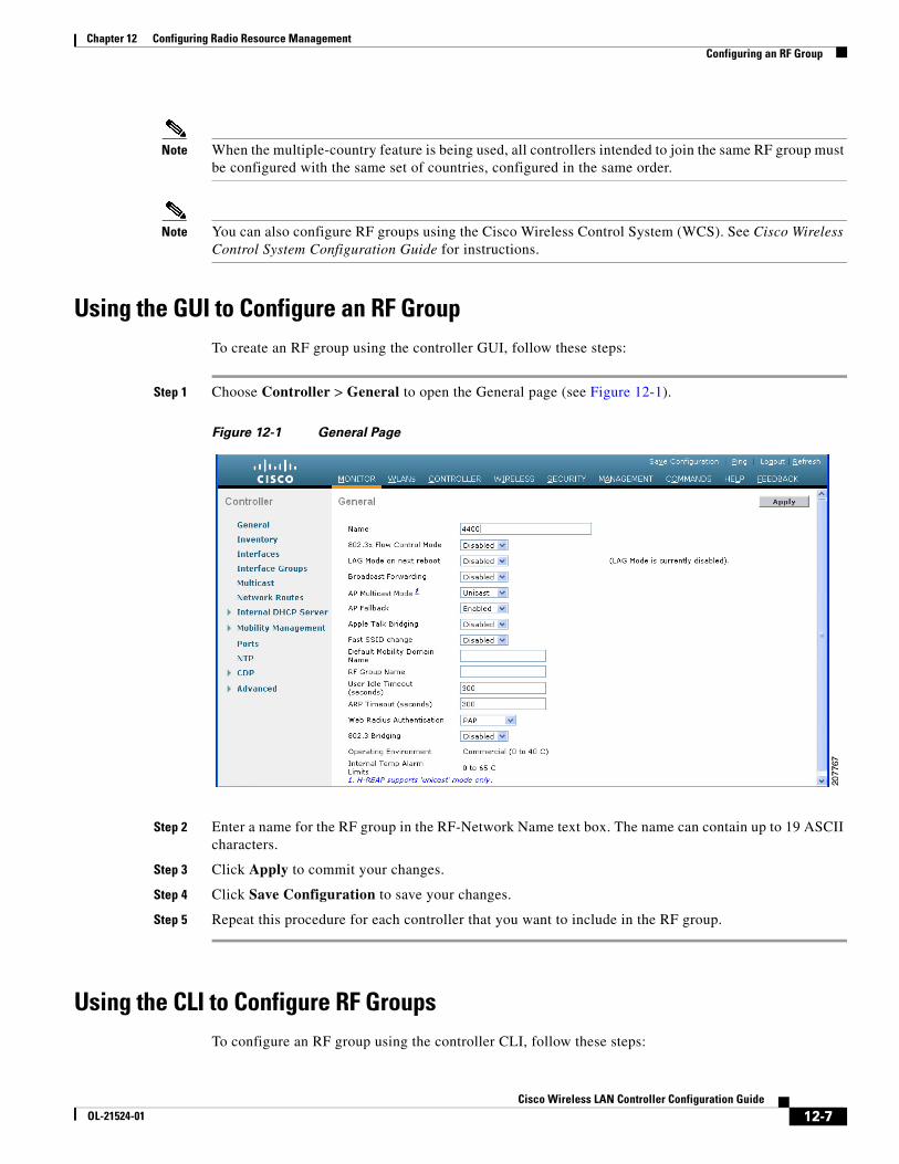
Step 1 Choose Controller > General to open the General page (see Figure 12-1).
Figure 12-1 General Page
Step 2 Enter a name for the RF group in the RF-Network Name text box. The name can contain up to 19 ASCII characters.
Step 3 Click Apply to commit your changes.
Step 4 Click Save Configuration to save your changes.
Step 5 Repeat this procedure for each controller that you want to include in the RF group.
Using the CLI to Configure RF GroupsTo configure an RF group using the controller CLI, follow these steps:
12-7Cisco Wireless LAN Controller Configuration Guide
OL-21524-01
Chapter 12 Configuring Radio Resource ManagementViewing the RF Group Status
Step 1 Create an RF group by entering the config network rf-network-name name command:
Note Enter up to 19 ASCII characters for the group name.
Step 2 View the RF group by entering the show network command.
Step 3 Save your settings by entering the save config command.
Step 4 Repeat this procedure for each controller that you want to include in the RF group.
Viewing the RF Group StatusThis section describes how to view the status of the RF group through either the GUI or the CLI.
Note You can also view the status of RF groups using the Cisco Wireless Control System (WCS). See Cisco Wireless Control System Configuration Guide for instructions.
Using the GUI to View RF Group StatusTo view the status of the RF group using the controller GUI, follow these steps:
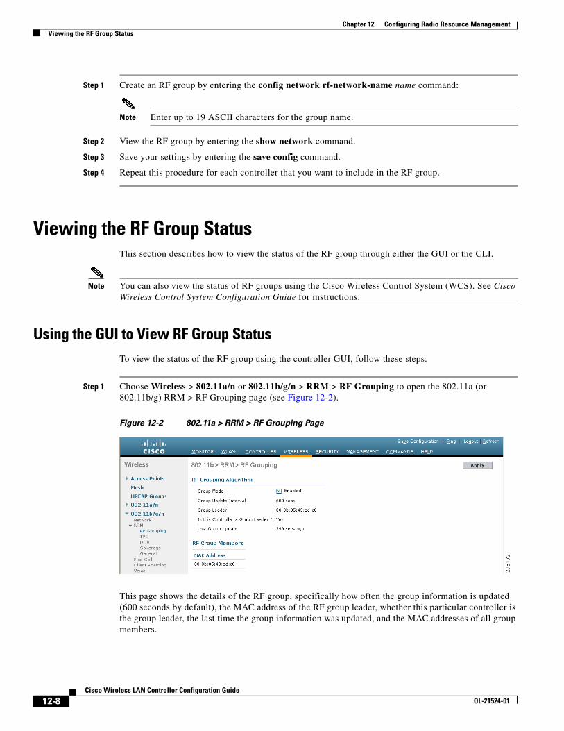
Step 1 Choose Wireless > 802.11a/n or 802.11b/g/n > RRM > RF Grouping to open the 802.11a (or 802.11b/g) RRM > RF Grouping page (see Figure 12-2).
Figure 12-2 802.11a > RRM > RF Grouping Page
This page shows the details of the RF group, specifically how often the group information is updated (600 seconds by default), the MAC address of the RF group leader, whether this particular controller is the group leader, the last time the group information was updated, and the MAC addresses of all group members.
12-8Cisco Wireless LAN Controller Configuration Guide
OL-21524-01
Chapter 12 Configuring Radio Resource ManagementViewing the RF Group Status
Note Automatic RF grouping, which is set through the Group Mode check box, is enabled by default. See the “Using the GUI to Configure RF Group Mode” section on page 12-11 for more information on this parameter.
Step 2 (Optional) Repeat this procedure for the network type that you did not select (802.11a or 802.11b/g).
12-9Cisco Wireless LAN Controller Configuration Guide
OL-21524-01
Chapter 12 Configuring Radio Resource ManagementConfiguring RRM
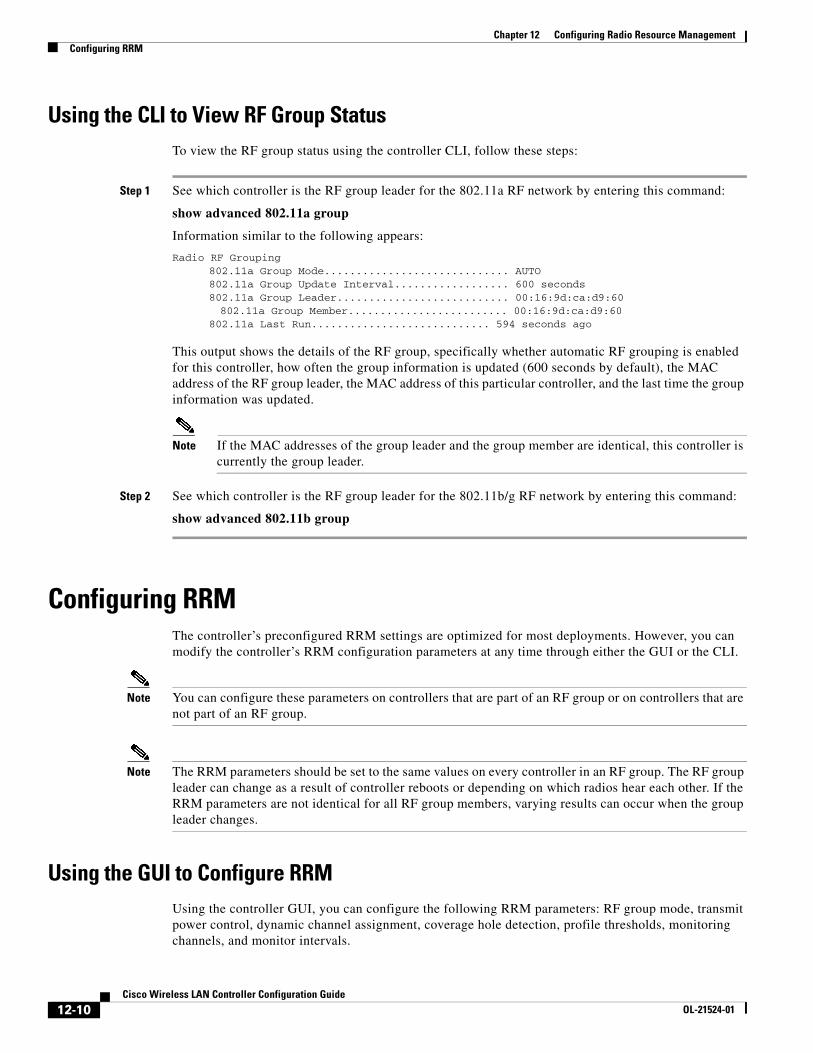
Using the CLI to View RF Group StatusTo view the RF group status using the controller CLI, follow these steps:
Step 1 See which controller is the RF group leader for the 802.11a RF network by entering this command:
show advanced 802.11a group
Information similar to the following appears:
Radio RF Grouping 802.11a Group Mode............................. AUTO 802.11a Group Update Interval.................. 600 seconds 802.11a Group Leader........................... 00:16:9d:ca:d9:60 802.11a Group Member......................... 00:16:9d:ca:d9:60 802.11a Last Run............................ 594 seconds ago
This output shows the details of the RF group, specifically whether automatic RF grouping is enabled for this controller, how often the group information is updated (600 seconds by default), the MAC address of the RF group leader, the MAC address of this particular controller, and the last time the group information was updated.
Note If the MAC addresses of the group leader and the group member are identical, this controller is currently the group leader.
Step 2 See which controller is the RF group leader for the 802.11b/g RF network by entering this command:
show advanced 802.11b group
Configuring RRMThe controller’s preconfigured RRM settings are optimized for most deployments. However, you can modify the controller’s RRM configuration parameters at any time through either the GUI or the CLI.
Note You can configure these parameters on controllers that are part of an RF group or on controllers that are not part of an RF group.
Note The RRM parameters should be set to the same values on every controller in an RF group. The RF group leader can change as a result of controller reboots or depending on which radios hear each other. If the RRM parameters are not identical for all RF group members, varying results can occur when the group leader changes.
Using the GUI to Configure RRMUsing the controller GUI, you can configure the following RRM parameters: RF group mode, transmit power control, dynamic channel assignment, coverage hole detection, profile thresholds, monitoring channels, and monitor intervals.
12-10Cisco Wireless LAN Controller Configuration Guide
OL-21524-01
Chapter 12 Configuring Radio Resource ManagementConfiguring RRM
Using the GUI to Configure RF Group Mode
To configure RF group mode using the controller GUI, follow these steps:
Step 1 Choose Wireless > 802.11a/n or 802.11b/g/n > RRM > RF Grouping to open the 802.11a (or 802.11b/g) RRM > RF Grouping page (see Figure 12-2).
Step 2 Select the Group Mode check box to enable this controller to participate in an RF group, or unselect it to disable this feature. If you enable this feature, the controller automatically forms an RF group with other controllers, and the group dynamically elects a leader to optimize RMM parameter settings for the the group. If you disable it, the controller does not participate in automatic RF grouping; instead it optimizes the access points connected directly to it. The default value is selected.
Note We recommend that controllers participate in automatic RF grouping. You can override RRM settings without disabling automatic RF group participation. See the “Overriding RRM” section on page 12-29 for instructions.
Step 3 Click Apply to commit your changes.
Step 4 Click Save Configuration to save your changes.
Using the GUI to Configure Transmit Power Control
To configure transmit power control settings using the controller GUI, follow these steps:
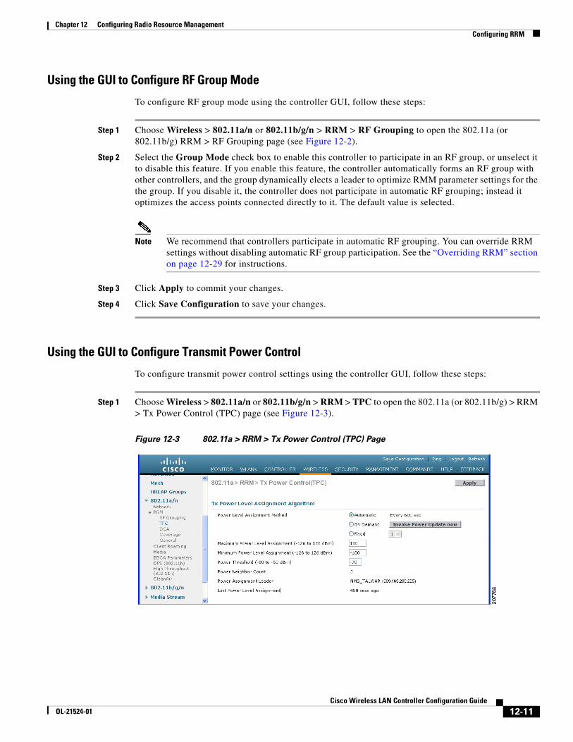
Step 1 Choose Wireless > 802.11a/n or 802.11b/g/n > RRM > TPC to open the 802.11a (or 802.11b/g) > RRM > Tx Power Control (TPC) page (see Figure 12-3).
Figure 12-3 802.11a > RRM > Tx Power Control (TPC) Page
12-11Cisco Wireless LAN Controller Configuration Guide
OL-21524-01
Chapter 12 Configuring Radio Resource ManagementConfiguring RRM
Step 2 Choose one of the following options from the Power Level Assignment Method drop-down list to specify the controller’s dynamic power assignment mode:
• Automatic—Causes the controller to periodically evaluate and, if necessary, update the transmit power for all joined access points. This is the default value.
• On Demand—Causes the controller to periodically evaluate the transmit power for all joined access points. However, the controller updates the power, if necessary, only when you click Invoke Power Update Now.
Note The controller does not evaluate and update the transmit power immediately after you click Invoke Power Update Now. It waits for the next 600-second interval. This value is not configurable.
• Fixed—Prevents the controller from evaluating and, if necessary, updating the transmit power for joined access points. The power level is set to the fixed value chosen from the drop-down list.
Note The transmit power level is assigned an integer value instead of a value in mW or dBm. The integer corresponds to a power level that varies depending on the regulatory domain in which the access points are deployed. See Step 7 on page 12-33 for information on available transmit power levels.
Note For optimal performance, we recommend that you use the Automatic setting. See the “Disabling Dynamic Channel and Power Assignment Globally for a Controller” section on page 12-36 for instructions if you need to disable the controller’s dynamic channel and power settings.
Step 3 Enter the maximum and minimum power level assignment values in the Maximum Power Level Assignment and Minimum Power Level Assignment text boxes.
The range for the Maximum Power Level Assignment is -10 to 30 dBm.
The range for the Minimum Power Level Assignment is -10 to 30 dBm.
Step 4 In the Power Threshold text box, enter the cutoff signal level used by RRM when determining whether to reduce an access point’s power. The default value for this parameter is –70 dBm but can be changed when access points are transmitting at higher (or lower) than desired power levels.
The range for this parameter is –80 to –50 dBm. Increasing this value (between –65 and –50 dBm) causes the access points to operate at higher transmit power rates. Decreasing the value has the opposite effect.
In applications with a dense population of access points, it may be useful to decrease the threshold to –80 or –75 dBm to reduce the number of BSSIDs (access points) and beacons seen by the wireless clients. Some wireless clients might have difficulty processing a large number of BSSIDs or a high beacon rate and might exhibit problematic behavior with the default threshold.
This page also shows the following nonconfigurable transmit power level parameter settings:
• Power Neighbor Count—The minimum number of neighbors an access point must have for the transmit power control algorithm to run.
• Power Assignment Leader—The MAC address of the RF group leader, which is responsible for power level assignment.
• Last Power Level Assignment—The last time RRM evaluated the current transmit power level assignments.
12-12Cisco Wireless LAN Controller Configuration Guide
OL-21524-01
Chapter 12 Configuring Radio Resource ManagementConfiguring RRM
Step 5 Click Apply to commit your changes.
Step 6 Click Save Configuration to save your changes.
Off-Channel Scanning Defer
In deployments with certain power-save clients, you sometimes need to defer RRM's normal off-channel scanning to avoid missing critical information from low-volume clients (for example, medical devices that use power-save mode and periodically send telemetry information). This feature improves the way that QoS interacts with the RRM scan defer feature.
You can use a client's WMM UP marking to configure the access point to defer off-channel scanning for a configurable period of time if it receives a packet marked UP.
Off-Channel Scanning Defer is essential to the operation of RRM, which gathers information about alternate channel choices such as noise and interference. Additionally, Off-Channel Scanning Defer is responsible for rogue detection. Devices that need to defer Off-Channel Scanning Defer should use the same WLAN as often as possible. If there are many of these devices (and the possibility exists that Off-Channel Defer scanning could be completely disabled by the use of this feature), you should implement an alternative to local AP Off-Channel Scanning Defer, such as monitor access points, or other access points in the same location that do not have this WLAN assigned.
Assignment of a QoS policy (bronze, silver, gold, and platinum) to a WLAN affects how packets are marked on the downlink connection from the access point regardless of how they were received on the uplink from the client. UP=1,2 is the lowest priority, and UP=0,3 is the next higher priority. The marking results of each QoS policy are as follows:
• Bronze marks all downlink traffic to UP= 1.
• Silver marks all downlink traffic to UP= 0.
• Gold marks all downlink traffic to UP=4.
• Platinum marks all downlink traffic to UP=6.
Using the GUI to Configure Off-Channel Scanning Defer for a WLAN
To configure Off-Channel Scanning Defer for a WLAN using the controller, follow these steps:
Step 1 Choose WLANs to open the WLANs page.
Step 2 Click the ID number of the WLAN to which you want to configure off-channel scanning Defer.
Step 3 Choose the Advanced tab from the WLANs > Edit page.
Step 4 From the Off Channel Scanning Defer section, set the Scan Defer Priority by clicking on the priority argument.
Step 5 Set the time in milliseconds in the Scan Defer Time text box.
Valid values are 100 through 60000. The default value is 100 milliseconds.
Step 6 Click Apply to save your configuration.
12-13Cisco Wireless LAN Controller Configuration Guide
OL-21524-01
Chapter 12 Configuring Radio Resource ManagementConfiguring RRM
Using the CLI to Configure Off Channel Scanning Defer for a WLAN
To configure the controller to defer normal off-channel scanning for a WLAN using the controller GUI, follow these steps:
Step 1 Assign a defer-priority for the channel scan by entering this command:
config wlan channel-scan defer-priority priority [enable | disable] WLAN-id
The valid range for the priority argument is 0 to 7.
The priority is 0 to 7 (this value should be set to 6 on the client and on the WLAN).
Use this command to configure the amount of time that scanning will be deferred following an UP packet in the queue.
Step 2 Assign the channel scan defer time (in milliseconds) by entering this command:
config wlan channel-scan defer-time msec WLAN-id
The time value is in miliseconds (ms) and the valid range is 100 (default) to 60000 (60 seconds). This setting should match the requirements of the equipment on your wireless LAN.
You can also configure this feature on the controller GUI by selecting WLANs, and either edit an existing WLAN or create a new one.
Overriding the TPC Algorithm with Minimum and Maximum Transmit Power Settings
The TPC algorithm has undergone a major rework in this release and it should do an adequate job of balancing RF power in many diverse RF environments. However, it is possible that automatic power control will not be able to resolve some scenarios in which an adequate RF design was not possible to implement due to architectural restrictions or site restrictions—for example, when all access points must be mounted in a central hallway, placing the access points close together, but requiring coverage out to the edge of the building.
In these scenarios, you can configure maximum and minimum transmit power limits to override TPC recommendations. The maximum and minimum TPC power settings only apply to access points attached to a controller from which they are configured; it is not a global RRM command. The default settings essentially disable this feature, and you should use care when overriding TPC recommendations.
To set the Maximum Power Level Assignment and Minimum Power Level Assignment text boxes, enter the maximum and minimum transmit power used by RRM on the Tx Power Control page. The range for these parameters is -10 to 30 dBM. The minimum value cannot be greater than the maximum value; the maximum value cannot be less than the minimum value.
If you configure a maximum transmit power, RRM does not allow any access point attached to the controller to exceed this transmit power level (whether the power is set by RRM TPC or by coverage hole detection). For example, if you configure a maximum transmit power of 11 dBm, then no access point would transmit above 11 dBm, unless the access point is configured manually.
Using the GUI to Configure Dynamic Channel Assignment
To specify the channels that the dynamic channel assignment (DCA) algorithm considers when selecting the channels to be used for RRM scanning using the controller GUI, follow these steps:
12-14Cisco Wireless LAN Controller Configuration Guide
OL-21524-01
Chapter 12 Configuring Radio Resource ManagementConfiguring RRM
Note This functionality is helpful when you know that the clients do not support certain channels because they are legacy devices or they have certain regulatory restrictions.
Step 1 Disable the 802.11a or 802.11b/g network as follows:
a. Choose Wireless > 802.11a/n or 802.11b/g/n > Network to open the 802.11a (or 802.11b/g) Global Parameters page.
b. Unselect the 802.11a (or 802.11b/g) Network Status check box.
c. Click Apply to commit your changes.
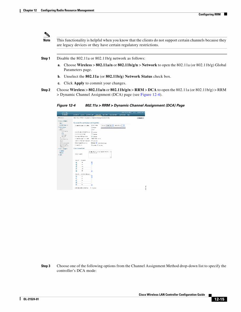
Step 2 Choose Wireless > 802.11a/n or 802.11b/g/n > RRM > DCA to open the 802.11a (or 802.11b/g) > RRM > Dynamic Channel Assignment (DCA) page (see Figure 12-4).
Figure 12-4 802.11a > RRM > Dynamic Channel Assignment (DCA) Page
Step 3 Choose one of the following options from the Channel Assignment Method drop-down list to specify the controller’s DCA mode:
12-15Cisco Wireless LAN Controller Configuration Guide
OL-21524-01
Chapter 12 Configuring Radio Resource ManagementConfiguring RRM
• Automatic—Causes the controller to periodically evaluate and, if necessary, update the channel assignment for all joined access points. This is the default value.
• Freeze—Causes the controller to evaluate and update the channel assignment for all joined access points, if necessary, but only when you click Invoke Channel Update Once.
Note The controller does not evaluate and update the channel assignment immediately after you click Invoke Channel Update Once. It waits for the next interval to elapse.
• OFF—Turns off DCA and sets all access point radios to the first channel of the band, which is the default value. If you choose this option, you must manually assign channels on all radios.
Note For optimal performance, we recommend that you use the Automatic setting. See the “Disabling Dynamic Channel and Power Assignment Globally for a Controller” section on page 12-36 for instructions if you need to disable the controller’s dynamic channel and power settings.
Step 4 From the Interval drop-down list, choose one of the following options to specify how often the DCA algorithm is allowed to run: 10 minutes, 1 hour, 2 hours, 3 hours, 4 hours, 6 hours, 8 hours, 12 hours, or 24 hours. The default value is 10 minutes.
Note If your controller supports only OfficeExtend access points, we recommend that you set the DCA interval to 6 hours for optimal performance. For deployments with a combination of OfficeExtend access points and local access points, the range of 10 minutes to 24 hours can be used.
Step 5 From the AnchorTime drop-down list, choose a number to specify the time of day when the DCA algorithm is to start. The options are numbers between 0 and 23 (inclusive) representing the hour of the day from 12:00 a.m. to 11:00 p.m.
Step 6 Select the Avoid Foreign AP Interference check box to cause the controller’s RRM algorithms to consider 802.11 traffic from foreign access points (those not included in your wireless network) when assigning channels to lightweight access points, or unselect it to disable this feature. For example, RRM may adjust the channel assignment to have access points avoid channels close to foreign access points. The default value is selected.
Step 7 Select the Avoid Cisco AP Load check box to cause the controller’s RRM algorithms to consider 802.11 traffic from Cisco lightweight access points in your wireless network when assigning channels, or unselect it to disable this feature. For example, RRM can assign better reuse patterns to access points that carry a heavier traffic load. The default value is unselected.
Step 8 Select the Avoid Non-802.11a (802.11b) Noise check box to cause the controller’s RRM algorithms to consider noise (non-802.11 traffic) in the channel when assigning channels to lightweight access points, or unselect it to disable this feature. For example, RRM may have access points avoid channels with significant interference from nonaccess point sources, such as microwave ovens. The default value is selected.
Step 9 Select the Avoid Persistent Non-WiFi Interference check box to enable the controller to ignore persistent non-WiFi interference.
Step 10 From the DCA Channel Sensitivity drop-down list, choose one of the following options to specify how sensitive the DCA algorithm is to environmental changes such as signal, load, noise, and interference when determining whether to change channels:
• Low—The DCA algorithm is not particularly sensitive to environmental changes.
12-16Cisco Wireless LAN Controller Configuration Guide
OL-21524-01
Chapter 12 Configuring Radio Resource ManagementConfiguring RRM
• Medium—The DCA algorithm is moderately sensitive to environmental changes.
• High—The DCA algorithm is highly sensitive to environmental changes.
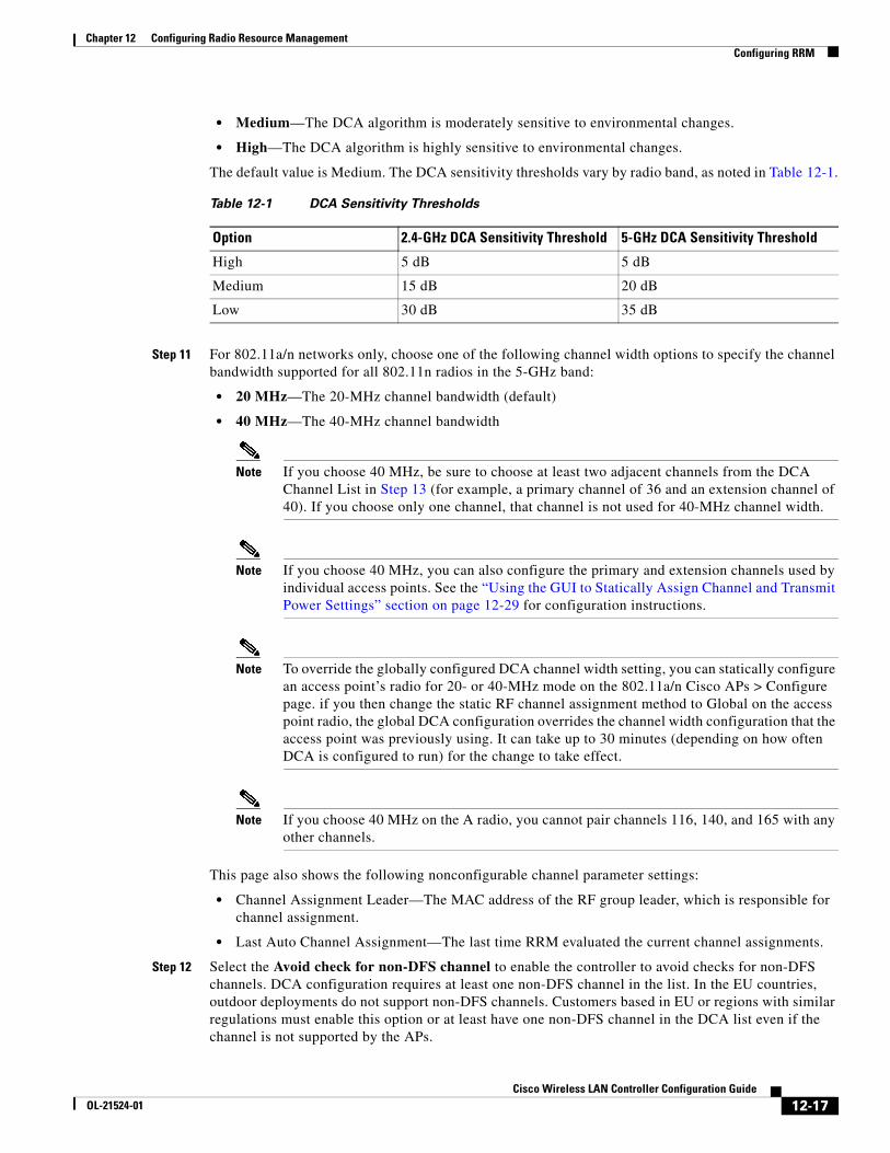
The default value is Medium. The DCA sensitivity thresholds vary by radio band, as noted in Table 12-1.
Step 11 For 802.11a/n networks only, choose one of the following channel width options to specify the channel bandwidth supported for all 802.11n radios in the 5-GHz band:
• 20 MHz—The 20-MHz channel bandwidth (default)
• 40 MHz—The 40-MHz channel bandwidth
Note If you choose 40 MHz, be sure to choose at least two adjacent channels from the DCA Channel List in Step 13 (for example, a primary channel of 36 and an extension channel of 40). If you choose only one channel, that channel is not used for 40-MHz channel width.
Note If you choose 40 MHz, you can also configure the primary and extension channels used by individual access points. See the “Using the GUI to Statically Assign Channel and Transmit Power Settings” section on page 12-29 for configuration instructions.
Note To override the globally configured DCA channel width setting, you can statically configure an access point’s radio for 20- or 40-MHz mode on the 802.11a/n Cisco APs > Configure page. if you then change the static RF channel assignment method to Global on the access point radio, the global DCA configuration overrides the channel width configuration that the access point was previously using. It can take up to 30 minutes (depending on how often DCA is configured to run) for the change to take effect.
Note If you choose 40 MHz on the A radio, you cannot pair channels 116, 140, and 165 with any other channels.
This page also shows the following nonconfigurable channel parameter settings:
• Channel Assignment Leader—The MAC address of the RF group leader, which is responsible for channel assignment.
• Last Auto Channel Assignment—The last time RRM evaluated the current channel assignments.
Step 12 Select the Avoid check for non-DFS channel to enable the controller to avoid checks for non-DFS channels. DCA configuration requires at least one non-DFS channel in the list. In the EU countries, outdoor deployments do not support non-DFS channels. Customers based in EU or regions with similar regulations must enable this option or at least have one non-DFS channel in the DCA list even if the channel is not supported by the APs.
Table 12-1 DCA Sensitivity Thresholds
Option 2.4-GHz DCA Sensitivity Threshold 5-GHz DCA Sensitivity Threshold
High 5 dB 5 dB
Medium 15 dB 20 dB
Low 30 dB 35 dB
12-17Cisco Wireless LAN Controller Configuration Guide
OL-21524-01
Chapter 12 Configuring Radio Resource ManagementConfiguring RRM
Note This parameter is applicable only for deployments having outdoor access points such as 1522 and 1524.
Step 13 In the DCA Channel List area, the DCA Channels text box shows the channels that are currently selected. To choose a channel, select its check box in the Select column. To exclude a channel, unselect its check box.
The ranges are as follows:802.11a—36, 40, 44, 48, 52, 56, 60, 64, 100, 104, 108, 112, 116, 132, 136, 140, 149, 153, 157, 161, 165, 190, 196802.11b/g—1, 2, 3, 4, 5, 6, 7, 8, 9, 10, 11
The defaults are as follows:802.11a—36, 40, 44, 48, 52, 56, 60, 64, 100, 104, 108, 112, 116, 132, 136, 140, 149, 153, 157, 161802.11b/g—1, 6, 11
Note These extended UNII-2 channels in the 802.11a band do not appear in the channel list: 100, 104, 108, 112, 116, 132, 136, and 140. If you have Cisco Aironet 1520 series mesh access points in the -E regulatory domain, you must include these channels in the DCA channel list before you start operation. If you are upgrading from a previous release, verify that these channels are included in the DCA channel list. To include these channels in the channel list, select the Extended UNII-2 Channels check box.
Step 14 If you are using Cisco Aironet 1520 series mesh access points in your network, you need to set the 4.9-GHz channels in the 802.11a band on which they are to operate. The 4.9-GHz band is for public safety client access traffic only. To choose a 4.9-GHz channel, select its check box in the Select column. To exclude a channel, unselect its check box.
The ranges are as follows:802.11a—1, 2, 3, 4, 5, 6, 7, 8, 9, 10, 11, 12, 13, 14, 15, 16, 17, 18, 19, 20, 21, 22, 23, 24, 25, 26
The defaults are as follows:802.11a—20, 26
Step 15 Click Apply to commit your changes.
Step 16 Reenable the 802.11a or 802.11b/g network as follows:
a. Choose Wireless > 802.11a/n or 802.11b/g/n > Network to open the 802.11a (or 802.11b/g) Global Parameters page.
b. Select the 802.11a (or 802.11b/g) Network Status check box.
c. Click Apply to commit your changes.
Step 17 Click Save Configuration to save your changes.
Note To see why the DCA algorithm changed channels, choose Monitor and then choose View All under Most Recent Traps. The trap provides the MAC address of the radio that changed channels, the previous channel and the new channel, the reason why the change occurred, the energy before and after the change, the noise before and after the change, and the interference before and after the change.
12-18Cisco Wireless LAN Controller Configuration Guide
OL-21524-01
Chapter 12 Configuring Radio Resource ManagementConfiguring RRM
Using the GUI to Configure Coverage Hole Detection
To enable coverage hole detection using the controller GUI, follow these steps:
Note In controller software release 5.2 or later releases, you can disable coverage hole detection on a per-WLAN basis. See the “Disabling Coverage Hole Detection per WLAN” section on page 7-64 for more information.
Step 1 Disable the 802.11a or 802.11b/g network as follows:
a. Choose Wireless > 802.11a/n or 802.11b/g/n > Network to open the 802.11a (or 802.11b/g) Global Parameters page.
b. Unselect the 802.11a (or 802.11b/g) Network Status check box.
c. Click Apply to commit your changes.
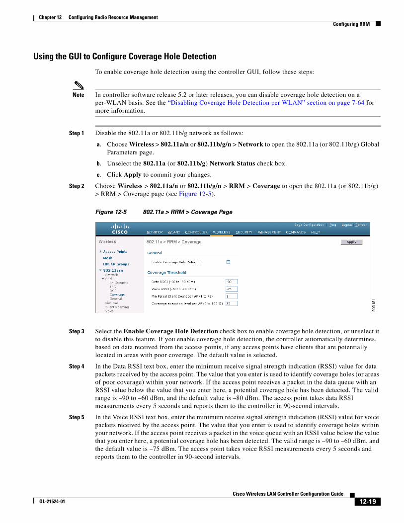
Step 2 Choose Wireless > 802.11a/n or 802.11b/g/n > RRM > Coverage to open the 802.11a (or 802.11b/g) > RRM > Coverage page (see Figure 12-5).
Figure 12-5 802.11a > RRM > Coverage Page
Step 3 Select the Enable Coverage Hole Detection check box to enable coverage hole detection, or unselect it to disable this feature. If you enable coverage hole detection, the controller automatically determines, based on data received from the access points, if any access points have clients that are potentially located in areas with poor coverage. The default value is selected.
Step 4 In the Data RSSI text box, enter the minimum receive signal strength indication (RSSI) value for data packets received by the access point. The value that you enter is used to identify coverage holes (or areas of poor coverage) within your network. If the access point receives a packet in the data queue with an RSSI value below the value that you enter here, a potential coverage hole has been detected. The valid range is –90 to –60 dBm, and the default value is –80 dBm. The access point takes data RSSI measurements every 5 seconds and reports them to the controller in 90-second intervals.
Step 5 In the Voice RSSI text box, enter the minimum receive signal strength indication (RSSI) value for voice packets received by the access point. The value that you enter is used to identify coverage holes within your network. If the access point receives a packet in the voice queue with an RSSI value below the value that you enter here, a potential coverage hole has been detected. The valid range is –90 to –60 dBm, and the default value is –75 dBm. The access point takes voice RSSI measurements every 5 seconds and reports them to the controller in 90-second intervals.
12-19Cisco Wireless LAN Controller Configuration Guide
OL-21524-01
Chapter 12 Configuring Radio Resource ManagementConfiguring RRM
Step 6 In the Min Failed Client Count per AP text box, enter the minimum number of clients on an access point with an RSSI value at or below the data or voice RSSI threshold. The valid range is 1 to 75, and the default value is 3.
Step 7 In the Coverage Exception Level per AP text box, enter the percentage of clients on an access point that are experiencing a low signal level but cannot roam to another access point. The valid range is 0 to 100%, and the default value is 25%.
Note If both the number and percentage of failed packets exceed the values configured for Failed Packet Count and Failed Packet Percentage (configurable through the controller CLI) for a 5-second period, the client is considered to be in a pre-alarm condition. The controller uses this information to distinguish between real and false coverage holes. False positives are generally due to the poor roaming logic implemented on most clients. A coverage hole is detected if both the number and percentage of failed clients meet or exceed the values entered in the Min Failed Client Count per AP and Coverage Exception Level per AP text boxes over a 90-second period. The controller determines if the coverage hole can be corrected and, if appropriate, mitigates the coverage hole by increasing the transmit power level for that specific access point.
Step 8 Click Apply to commit your changes.
Step 9 Reenable the 802.11a or 802.11b/g network as follows:
a. Choose Wireless > 802.11a/n or 802.11b/g/n > Network to open the 802.11a (or 802.11b/g) Global Parameters page.
b. Select the 802.11a (or 802.11b/g) Network Status check box.
c. Click Apply to commit your changes.
Step 10 Click Save Configuration to save your changes.
Using the GUI to Configure RRM Profile Thresholds, Monitoring Channels, and Monitor Intervals
To configure RRM profile thresholds, monitoring channels, and monitor intervals using the controller GUI, follow these steps:
Step 1 Choose Wireless > 802.11a/n or 802.11b/g/n > RRM > General to open the 802.11a (or 802.11b/g) > RRM > General page (see Figure 12-6).
12-20Cisco Wireless LAN Controller Configuration Guide
OL-21524-01
Chapter 12 Configuring Radio Resource ManagementConfiguring RRM
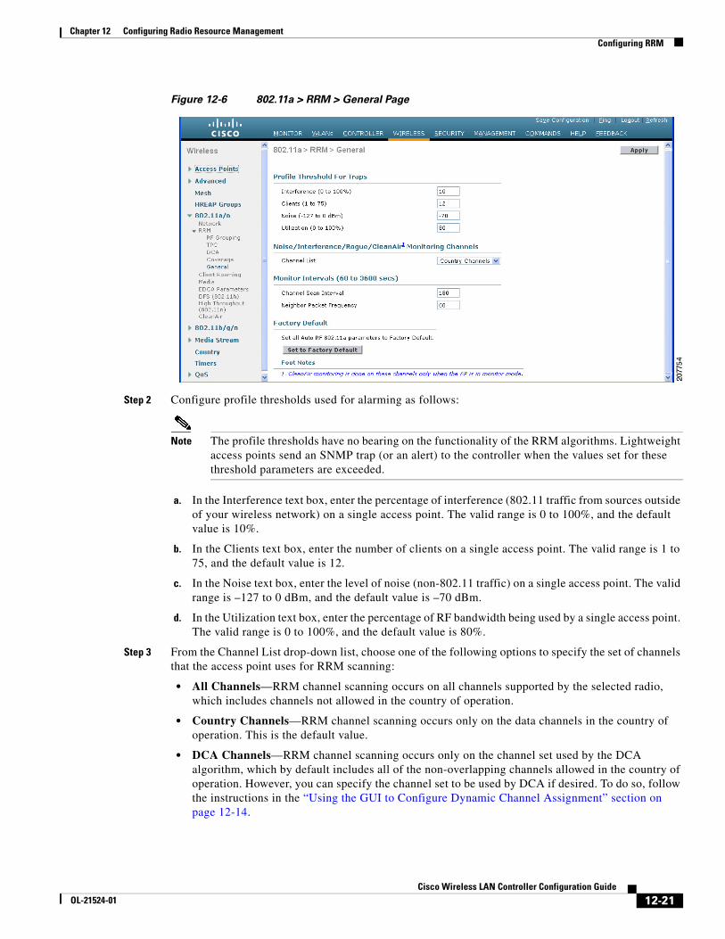
Figure 12-6 802.11a > RRM > General Page
Step 2 Configure profile thresholds used for alarming as follows:
Note The profile thresholds have no bearing on the functionality of the RRM algorithms. Lightweight access points send an SNMP trap (or an alert) to the controller when the values set for these threshold parameters are exceeded.
a. In the Interference text box, enter the percentage of interference (802.11 traffic from sources outside of your wireless network) on a single access point. The valid range is 0 to 100%, and the default value is 10%.
b. In the Clients text box, enter the number of clients on a single access point. The valid range is 1 to 75, and the default value is 12.
c. In the Noise text box, enter the level of noise (non-802.11 traffic) on a single access point. The valid range is –127 to 0 dBm, and the default value is –70 dBm.
d. In the Utilization text box, enter the percentage of RF bandwidth being used by a single access point. The valid range is 0 to 100%, and the default value is 80%.
Step 3 From the Channel List drop-down list, choose one of the following options to specify the set of channels that the access point uses for RRM scanning:
• All Channels—RRM channel scanning occurs on all channels supported by the selected radio, which includes channels not allowed in the country of operation.
• Country Channels—RRM channel scanning occurs only on the data channels in the country of operation. This is the default value.
• DCA Channels—RRM channel scanning occurs only on the channel set used by the DCA algorithm, which by default includes all of the non-overlapping channels allowed in the country of operation. However, you can specify the channel set to be used by DCA if desired. To do so, follow the instructions in the “Using the GUI to Configure Dynamic Channel Assignment” section on page 12-14.
12-21Cisco Wireless LAN Controller Configuration Guide
OL-21524-01
Chapter 12 Configuring Radio Resource ManagementConfiguring RRM
Step 4 Configure monitor intervals as follows:
a. In the Channel Scan Interval text box, enter (in seconds) the sum of the time between scans for each channel within a radio band. The entire scanning process takes 50 ms per channel, per radio and runs at the interval configured here. The time spent listening on each channel is determined by the non-configurable 50-ms scan time and the number of channels to be scanned. For example, in the U.S. all 11 802.11b/g channels are scanned for 50 ms each within the default 180-second interval. So every 16 seconds, 50 ms is spent listening on each scanned channel (180/11 = ~16 seconds). The Channel Scan Interval parameter determines the interval at which the scanning occurs.The valid range is 60 to 3600 seconds, and the default value is 60 seconds for 802.11a radios and 180 seconds for the 802.11b/g radios.
Note If your controller supports only OfficeExtend access points, we recommend that you set the channel scan interval to 1800 seconds for optimal performance. For deployments with a combination of OfficeExtend access points and local access points, the range of 60 to 3600 seconds can be used.
b. In the Neighbor Packet Frequency text box, enter (in seconds) how frequently neighbor packets (messages) are sent, which eventually builds the neighbor list. The valid range is 60 to 3600 seconds, and the default value is 60 seconds.
Note If your controller supports only OfficeExtend access points, we recommend that you set the neighbor packet frequency to 600 seconds for optimal performance. For deployments with a combination of OfficeExtend access points and local access points, the range of 60 to 3600 seconds can be used.
Note In controller software release 4.1.185.0 or later releases, if the access point radio does not receive a neighbor packet from an existing neighbor within 60 minutes, the controller deletes that neighbor from the neighbor list. In controller software releases prior to 4.1.185.0, the controller waits only 20 minutes before deleting an unresponsive neighbor radio from the neighbor list.
Step 5 Click Apply to commit your changes.
Step 6 Click Save Configuration to save your changes.
Note Click Set to Factory Default if you want to return all of the controller’s RRM parameters to their factory-default values.
Using the CLI to Configure RRMTo configure RRM using the controller CLI, follow these steps:
Step 1 Disable the 802.11a or 802.11b/g network by entering this command:
config {802.11a | 802.11b} disable network
12-22Cisco Wireless LAN Controller Configuration Guide
OL-21524-01
Chapter 12 Configuring Radio Resource ManagementConfiguring RRM
Step 2 Perform one of the following to configure transmit power control:
• To have RRM automatically set the transmit power for all 802.11a or 802.11b/g radios at periodic intervals, enter this command:
config {802.11a | 802.11b} txPower global auto
• To have RRM automatically reset the transmit power for all 802.11a or 802.11b/g radios one time, enter this command:
config {802.11a | 802.11b} txPower global once
• To configure the transmit power range that overrides the Transmit Power Control algorithm, use this command to enter the maximum and minimum transmit power used by RRM:
config {802.11a | 802.11b} txPower global {max | min} txpower
where txpower is a value from –126 to 126 dBM. The minimum value cannot be greater than the maximum value; the maximum value cannot be less than the minimum value.
If you configure a maximum transmit power, RRM does not allow any access point to exceed this transmit power (whether the maximum is set at RRM startup, or by coverage hole detection). For example, if you configure a maximum transmit power of 11 dBm, then no access point would transmit above 11 dBm, unless the access point is configured manually.
• To manually change the default transmit power setting of –70 dBm, enter this command:
config advanced {802.11a | 802.11b} tx-power-control-thresh threshold
where threshold is a value from –80 to –50 dBm. Increasing this value (between –65 and –50 dBm) causes the access points to operate at higher transmit power rates. Decreasing the value has the opposite effect.
In applications with a dense population of access points, it may be useful to decrease the threshold to –80 or –75 dBm in order to reduce the number of BSSIDs (access points) and beacons seen by the wireless clients. Some wireless clients may have difficulty processing a large number of BSSIDs or a high beacon rate and may exhibit problematic behavior with the default threshold.
Step 3 Perform one of the following to configure dynamic channel assignment (DCA):
• To have RRM automatically configure all 802.11a or 802.11b/g channels based on availability and interference, enter this command:
config {802.11a | 802.11b} channel global auto
• To have RRM automatically reconfigure all 802.11a or 802.11b/g channels one time based on availability and interference, enter this command:
config {802.11a | 802.11b} channel global once
• To disable RRM and set all channels to their default values, enter this command:
config {802.11a | 802.11b} channel global off
• To specify the channel set used for DCA, enter this command:
config advanced {802.11a | 802.11b} channel {add | delete} channel_number
You can enter only one channel number per command. This command is helpful when you know that the clients do not support certain channels because they are legacy devices or they have certain regulatory restrictions.
Step 4 Configure additional DCA parameters by entering these commands:
• config advanced {802.11a | 802.11b} channel dca anchor-time value—Specifies the time of day when the DCA algorithm is to start. value is a number between 0 and 23 (inclusive) representing the hour of the day from 12:00 a.m. to 11:00 p.m.
12-23Cisco Wireless LAN Controller Configuration Guide
OL-21524-01
Chapter 12 Configuring Radio Resource ManagementConfiguring RRM
• config advanced {802.11a | 802.11b} channel dca interval value—Specifies how often the DCA algorithm is allowed to run. value is one of the following: 1, 2, 3, 4, 6, 8, 12, or 24 hours or 0, which is the default value of 10 minutes (or 600 seconds).
Note If your controller supports only OfficeExtend access points, we recommend that you set the DCA interval to 6 hours for optimal performance. For deployments with a combination of OfficeExtend access points and local access points, the range of 10 minutes to 24 hours can be used.
• config advanced {802.11a | 802.11b} channel dca sensitivity {low | medium | high}—Specifies how sensitive the DCA algorithm is to environmental changes such as signal, load, noise, and interference when determining whether to change channel.
– low means that the DCA algorithm is not particularly sensitive to environmental changes.
– medium means that the DCA algorithm is moderately sensitive to environmental changes.
– high means that the DCA algorithm is highly sensitive to environmental changes.
The DCA sensitivity thresholds vary by radio band, as noted in Table 12-2.
• config advanced 802.11a channel dca chan-width-11n {20 | 40}—Configures the DCA channel width for all 802.11n radios in the 5-GHz band.
where
– 20 sets the channel width for 802.11n radios to 20 MHz. This is the default value.
– 40 sets the channel width for 802.11n radios to 40 MHz.
Note If you choose 40, be sure to set at least two adjacent channels in the config advanced 802.11a channel {add | delete} channel_number command in Step 3 (for example, a primary channel of 36 and an extension channel of 40). If you set only one channel, that channel is not used for 40-MHz channel width.
Note If you choose 40, you can also configure the primary and extension channels used by individual access points. See the “Using the CLI to Statically Assign Channel and Transmit Power Settings” section on page 12-34 for configuration instructions.
Table 12-2 DCA Sensitivity Thresholds
Option 2.4-GHz DCA Sensitivity Threshold 5-GHz DCA Sensitivity Threshold
High 5 dB 5 dB
Medium 15 dB 20 dB
Low 30 dB 35 dB
12-24Cisco Wireless LAN Controller Configuration Guide
OL-21524-01
Chapter 12 Configuring Radio Resource ManagementConfiguring RRM
Note To override the globally configured DCA channel width setting, you can statically configure an access point’s radio for 20- or 40-MHz mode using the config 802.11a chan_width Cisco_AP {20 | 40} command. if you then change the static configuration to global on the access point radio, the global DCA configuration overrides the channel width configuration that the access point was previously using. It can take up to 30 minutes (depending on how often DCA is configured to run) for the change to take effect.
• config advanced {802.11a | 802.11b} channel outdoor-ap-dca {enable | disable}—Enables or disables to the controller to avoid checks for non-DFS channels.
Note This parameter is applicable only for deployments having outdoor access points such as 1522 and 1524.
• config advanced {802.11a | 802.11b} channel foreign {enable | disable}—Enables or disables foreign access point interference avoidance in the channel assignment.
• config advanced {802.11a | 802.11b} channel load {enable | disable}—Enables or disables load avoidance in the channel assignment.
• config advanced {802.11a | 802.11b} channel noise {enable | disable}—Enables or disables noise avoidance in the channel assignment.
• config advanced {802.11a | 802.11b} channel update—Initiates an update of the channel selection for every Cisco access point.
Step 5 Configure coverage hole detection by entering these commands:
Note In controller software release 5.2 or later releases, you can disable coverage hole detection on a per-WLAN basis. See the “Disabling Coverage Hole Detection per WLAN” section on page 7-64 for more information.
• config advanced {802.11a | 802.11b} coverage {enable | disable}—Enables or disables coverage hole detection. If you enable coverage hole detection, the controller automatically determines, based on data received from the access points, if any access points have clients that are potentially located in areas with poor coverage. The default value is enabled.
• config advanced {802.11a | 802.11b} coverage {data | voice} rssi-threshold rssi—Specifies the minimum receive signal strength indication (RSSI) value for packets received by the access point. The value that you enter is used to identify coverage holes (or areas of poor coverage) within your network. If the access point receives a packet in the data or voice queue with an RSSI value below the value you enter here, a potential coverage hole has been detected. The valid range is –90 to –60 dBm, and the default value is –80 dBm for data packets and –75 dBm for voice packets. The access point takes RSSI measurements every 5 seconds and reports them to the controller in 90-second intervals.
• config advanced {802.11a | 802.11b} coverage level global clients—Specifies the minimum number of clients on an access point with an RSSI value at or below the data or voice RSSI threshold. The valid range is 1 to 75, and the default value is 3.
• config advanced {802.11a | 802.11b} coverage exception global percent—Specifies the percentage of clients on an access point that are experiencing a low signal level but cannot roam to another access point. The valid range is 0 to 100%, and the default value is 25%.
12-25Cisco Wireless LAN Controller Configuration Guide
OL-21524-01
Chapter 12 Configuring Radio Resource ManagementConfiguring RRM
• config advanced {802.11a | 802.11b} coverage {data | voice} packet-count packets—Specifies the minimum failure count threshold for uplink data or voice packets. The valid range is 1 to 255 packets, and the default value is 10 packets.
• config advanced {802.11a | 802.11b} coverage {data | voice} fail-rate percent—Specifies the failure rate threshold for uplink data or voice packets. The valid range is 1 to 100%, and the default value is 20%.
Note If both the number and percentage of failed packets exceed the values entered in the packet-count and fail-rate commands for a 5-second period, the client is considered to be in a pre-alarm condition. The controller uses this information to distinguish between real and false coverage holes. False positives are generally due to the poor roaming logic implemented on most clients. A coverage hole is detected if both the number and percentage of failed clients meet or exceed the values entered in the coverage level global and coverage exception global commands over a 90-second period. The controller determines if the coverage hole can be corrected and, if appropriate, mitigates the coverage hole by increasing the transmit power level for that specific access point.
Step 6 Enable the 802.11a or 802.11b/g network by entering this command:
config {802.11a | 802.11b} enable network
Note To enable the 802.11g network, enter config 802.11b 11gSupport enable after the config 802.11b enable network command.
Step 7 Save your settings by entering this command:
save config
Using the CLI to View RRM SettingsTo view 802.11a and 802.11b/g RRM settings, use these commands:
show advanced {802.11a | 802.11b} ?
where ? is one of the following:
• ccx {global | Cisco_AP}—Shows the CCX RRM configuration.
802.11a Client Beacon Measurements: disabled
• channel—Shows the channel assignment configuration and statistics.
Automatic Channel Assignment Channel Assignment Mode........................ ONCE Channel Update Interval........................ 600 seconds Anchor time (Hour of the day).................. 20 Channel Update Count........................... 0 Channel Update Contribution.................... S.IU Channel Assignment Leader...................... 00:0b:85:40:90:c0 Last Run....................................... 532 seconds ago DCA Sensitivity Level.......................... MEDIUM (20 dB) DCA 802.11n Channel Width...................... 40 MHz Channel Energy Levels
12-26Cisco Wireless LAN Controller Configuration Guide
OL-21524-01
Chapter 12 Configuring Radio Resource ManagementConfiguring RRM
Minimum...................................... unknown Average...................................... unknown Maximum...................................... unknown Channel Dwell Times Minimum...................................... unknown Average...................................... unknown Maximum...................................... unknown Auto-RF Allowed Channel List................... 36,40 Auto-RF Unused Channel List.................... 44,48,52,56,60,64,100,104, .......................................... 108,112,116,132,136,140,149,
............................................. 153,157,161,165,190,196 DCA Outdoor AP option....................... Disabled
• coverage—Shows the coverage hole detection configuration and statistics.
Coverage Hole Detection 802.11a Coverage Hole Detection Mode........... Enabled 802.11a Coverage Voice Packet Count............ 10 packets 802.11a Coverage Voice Packet Percentage....... 20% 802.11a Coverage Voice RSSI Threshold.......... -75 dBm 802.11a Coverage Data Packet Count............. 10 packets 802.11a Coverage Data Packet Percentage........ 20% 802.11a Coverage Data RSSI Threshold........... -80 dBm 802.11a Global coverage exception level........ 25% 802.11a Global client minimum exception lev. 3 clients
• logging—Shows the RF event and performance logging.
RF Event and Performance Logging Channel Update Logging......................... Off Coverage Profile Logging....................... Off Foreign Profile Logging........................ Off Load Profile Logging........................... Off Noise Profile Logging.......................... Off Performance Profile Logging.................... Off TxPower Update Logging...................... Off
• monitor—Shows the Cisco radio monitoring.
Default 802.11a AP monitoring 802.11a Monitor Mode........................... enable 802.11a Monitor Channels....................... Country channels 802.11a AP Coverage Interval................... 180 seconds 802.11a AP Load Interval....................... 60 seconds 802.11a AP Noise Interval...................... 180 seconds 802.11a AP Signal Strength Interval......... 60 seconds
• profile {global | Cisco_AP}—Shows the access point performance profiles.
Default 802.11a AP performance profiles 802.11a Global Interference threshold.......... 10% 802.11a Global noise threshold................. -70 dBm 802.11a Global RF utilization threshold........ 80% 802.11a Global throughput threshold............ 1000000 bps 802.11a Global clients threshold............ 12 clients
• receiver—Shows the 802.11a or 802.11b/g receiver configuration and statistics.
802.11a Advanced Receiver Settings RxStart : Signal Threshold..................... 15 RxStart : Signal Jump Threshold................ 5 RxStart : Preamble Power Threshold............. 2 RxRestart: Signal Jump Status................... Enabled RxRestart: Signal Jump Threshold................ 10 TxStomp : Low RSSI Status...................... Enabled
12-27Cisco Wireless LAN Controller Configuration Guide
OL-21524-01
Chapter 12 Configuring Radio Resource ManagementConfiguring RRM
TxStomp : Low RSSI Threshold................... 30 TxStomp : Wrong BSSID Status................... Enabled TxStomp : Wrong BSSID Data Only Status......... Enabled RxAbort : Raw Power Drop Status................ Disabled RxAbort : Raw Power Drop Threshold............. 10 RxAbort : Low RSSI Status...................... Disabled RxAbort : Low RSSI Threshold................... 0 RxAbort : Wrong BSSID Status................... Disabled RxAbort : Wrong BSSID Data Only Status......... Disabled --------------------------------------------.... pico-cell-V2 parameters in dbm units:...........
RxSensitivity: Min,Max,Current RxSense Thres.... 0,0,0 CCA Threshold: Min,Max,Current Clear Channel.... 0,0,0Tx Pwr: Min,Max,Current Transmit Power for A.... 0,0,0 --------------------------------------------....
• summary—Shows the configuration and statistics of the 802.11a or 802.11b/g access points.
AP Name MAC Address Admin State Operation State Channel TxPower-------- ------------------ ------------- --------------- -------- -------AP1140 00:22:90:96:5b:d0 ENABLED DOWN 64* 1(*)AP1240 00:21:1b:ea:36:60 ENABLED DOWN 161* 1(*)AP1130 00:1f:ca:cf:b6:60 ENABLED REGISTERED 48* 1(*)
• txpower—Shows the transmit power assignment configuration and statistics.
Automatic Transmit Power Assignment Transmit Power Assignment Mode................. AUTO Transmit Power Update Interval................. 600 seconds Transmit Power Update Count.................... 0 Transmit Power Threshold....................... -70 dBm Transmit Power Neighbor Count.................. 3 APs
Min Transmit Power............................. -100 dBm Max Transmit Power............................. 100 dBm Transmit Power Update Contribution............. SNI. Transmit Power Assignment Leader............... 00:0b:85:40:90:c0 Last Run....................................... 354 seconds ago
Using the CLI to Debug RRM IssuesUse these commands to troubleshoot and verify RRM behavior:
debug airewave-director ?
where ? is one of the following:
• all—Enables debugging for all RRM logs.
• channel—Enables debugging for the RRM channel assignment protocol.
• detail—Enables debugging for RRM detail logs.
• error—Enables debugging for RRM error logs.
• group—Enables debugging for the RRM grouping protocol.
• manager—Enables debugging for the RRM manager.
• message—Enables debugging for RRM messages.
• packet—Enables debugging for RRM packets.
• power—Enables debugging for the RRM power assignment protocol as well as coverage hole detection.
12-28Cisco Wireless LAN Controller Configuration Guide
OL-21524-01
Chapter 12 Configuring Radio Resource ManagementOverriding RRM
• profile—Enables debugging for RRM profile events.
• radar—Enables debugging for the RRM radar detection/avoidance protocol.
• rf-change—Enables debugging for RRM RF changes.
Overriding RRMIn some deployments, it is desirable to statically assign channel and transmit power settings to the access points instead of relying on the RRM algorithms provided by Cisco. Typically, this is true in challenging RF environments and non-standard deployments but not the more typical carpeted offices.
Note If you choose to statically assign channels and power levels to your access points and/or to disable dynamic channel and power assignment, you should still use automatic RF grouping to avoid spurious rogue device events.
You can disable dynamic channel and power assignment globally for a controller, or you can leave dynamic channel and power assignment enabled and statically configure specific access point radios with a channel and power setting. Follow the instructions in one of the following sections:
• Statically Assigning Channel and Transmit Power Settings to Access Point Radios, page 12-29
• Disabling Dynamic Channel and Power Assignment Globally for a Controller, page 12-36
Note While you can specify a global default transmit power parameter for each network type that applies to all the access point radios on a controller, you must set the channel for each access point radio when you disable dynamic channel assignment. You may also want to set the transmit power for each access point instead of leaving the global transmit power in effect.
Statically Assigning Channel and Transmit Power Settings to Access Point Radios
This section provides instructions for statically assigning channel and power settings using the GUI or CLI.
Note We recommend that you assign different nonoverlapping channels to access points that are within close proximity to each other. The nonoverlapping channels in the U.S. are 36, 40, 44, 48, 52, 56, 60, 64, 149, 153, 157, and 161 in an 802.11a network and 1, 6, and 11 in an 802.11b/g network.
Note We recommend that you do not assign all access points that are within close proximity to each other to the maximum power level.
Using the GUI to Statically Assign Channel and Transmit Power Settings
To statically assign channel and/or power settings on a per access point radio basis using the GUI, follow these steps:
12-29Cisco Wireless LAN Controller Configuration Guide
OL-21524-01
Chapter 12 Configuring Radio Resource ManagementOverriding RRM
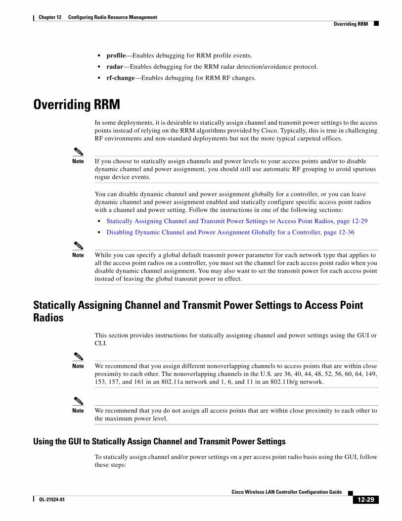
Step 1 Choose Wireless > Access Points > Radios > 802.11a/n or 802.11b/g/n to open the 802.11a/n (or 802.11b/g/n) Radios page (see Figure 12-7).
Figure 12-7 802.11a/n Radios Page
This page shows all the 802.11a/n or 802.11b/g/n access point radios that are joined to the controller and their current settings. The Channel text box shows both the primary and extension channels and uses an asterisk to indicate if they are globally assigned.
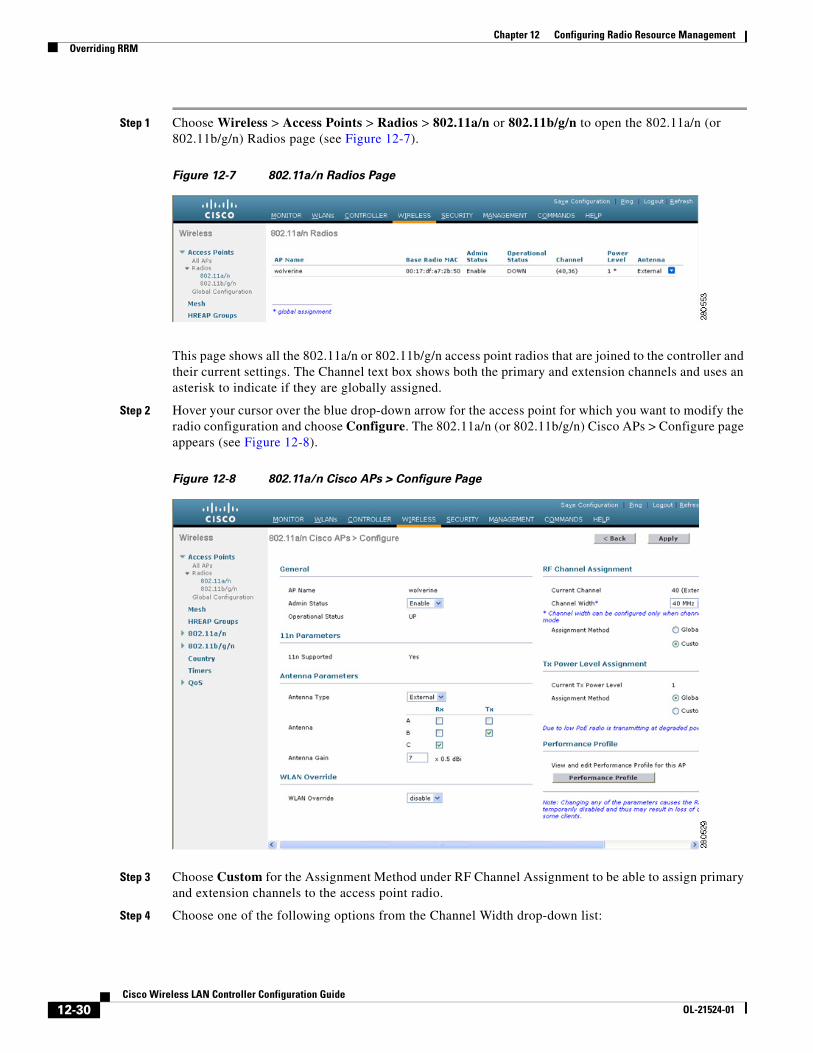
Step 2 Hover your cursor over the blue drop-down arrow for the access point for which you want to modify the radio configuration and choose Configure. The 802.11a/n (or 802.11b/g/n) Cisco APs > Configure page appears (see Figure 12-8).
Figure 12-8 802.11a/n Cisco APs > Configure Page
Step 3 Choose Custom for the Assignment Method under RF Channel Assignment to be able to assign primary and extension channels to the access point radio.
Step 4 Choose one of the following options from the Channel Width drop-down list:
12-30Cisco Wireless LAN Controller Configuration Guide
OL-21524-01
Chapter 12 Configuring Radio Resource ManagementOverriding RRM
• 20 MHz—Allows the radio to communicate using only 20-MHz channels. Choose this option for legacy 802.11a radios, 20-MHz 802.11n radios, or 40-MHz 802.11n radios that you want to operate using only 20-MHz channels. This is the default value.
• 40 MHz—Allows 40-MHz 802.11n radios to communicate using two adjacent 20-MHz channels bonded together. The radio uses the primary channel that you choose in Step 6 as well as its extension channel for faster throughput. Each channel has only one extension channel (36 and 40 are a pair, 44 and 48 are a pair, and so on). For example, if you choose a primary channel of 44, the controller would use channel 48 as the extension channel. If you choose a primary channel of 48, the controller would use channel 44 as the extension channel.
Note You cannot configure access points supporting 40 MHz channel width on 2.4 GHz.
Note The Channel Width parameter can be configured for 802.11a/n radios only if the RF channel assignment method is in custom mode.
Note Statically configuring an access point’s radio for 20- or 40-MHz mode overrides the globally configured DCA channel width setting on the 802.11a > RRM > Dynamic Channel Assignment (DCA) page. If you change the static RF channel assignment method back to Global on the access point radio, the global DCA configuration overrides the channel width configuration that the access point was previously using. It can take up to 30 minutes (depending on how often DCA is configured to run) for the change to take effect.
Figure 12-9 shows channel bonding in the 5-GHz band. Low channels are preferred.
Note Channels 116, 120, 124, and 128 are not available in the U.S. and Canada for 40-MHz channel bonding.
12-31Cisco Wireless LAN Controller Configuration Guide
OL-21524-01
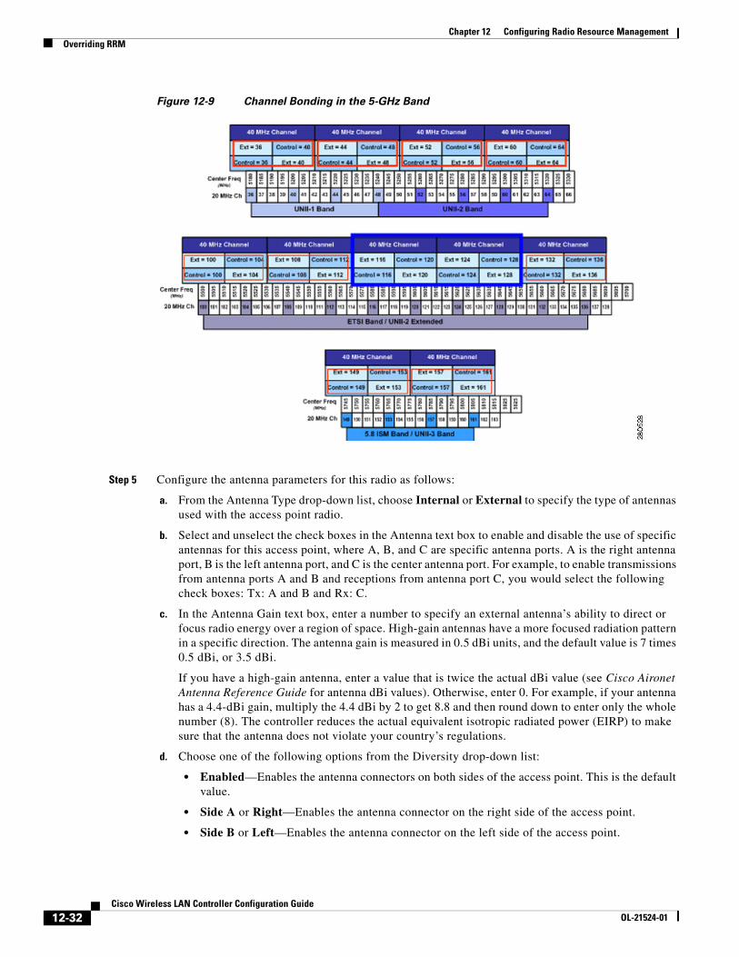
Chapter 12 Configuring Radio Resource ManagementOverriding RRM
Figure 12-9 Channel Bonding in the 5-GHz Band
Step 5 Configure the antenna parameters for this radio as follows:
a. From the Antenna Type drop-down list, choose Internal or External to specify the type of antennas used with the access point radio.
b. Select and unselect the check boxes in the Antenna text box to enable and disable the use of specific antennas for this access point, where A, B, and C are specific antenna ports. A is the right antenna port, B is the left antenna port, and C is the center antenna port. For example, to enable transmissions from antenna ports A and B and receptions from antenna port C, you would select the following check boxes: Tx: A and B and Rx: C.
c. In the Antenna Gain text box, enter a number to specify an external antenna’s ability to direct or focus radio energy over a region of space. High-gain antennas have a more focused radiation pattern in a specific direction. The antenna gain is measured in 0.5 dBi units, and the default value is 7 times 0.5 dBi, or 3.5 dBi.
If you have a high-gain antenna, enter a value that is twice the actual dBi value (see Cisco Aironet Antenna Reference Guide for antenna dBi values). Otherwise, enter 0. For example, if your antenna has a 4.4-dBi gain, multiply the 4.4 dBi by 2 to get 8.8 and then round down to enter only the whole number (8). The controller reduces the actual equivalent isotropic radiated power (EIRP) to make sure that the antenna does not violate your country’s regulations.
d. Choose one of the following options from the Diversity drop-down list:
• Enabled—Enables the antenna connectors on both sides of the access point. This is the default value.
• Side A or Right—Enables the antenna connector on the right side of the access point.
• Side B or Left—Enables the antenna connector on the left side of the access point.
12-32Cisco Wireless LAN Controller Configuration Guide
OL-21524-01
Chapter 12 Configuring Radio Resource ManagementOverriding RRM
Step 6 Choose Custom for the Assignment Method under RF Channel Assignment and choose a channel from the drop-down list to assign an RF channel to the access point radio.
The channel you choose is the primary channel (for example, channel 36), which is used for communication by legacy 802.11a radios and 802.11n 20-MHz radios. 802.11n 40-MHz radios use this channel as the primary channel but also use an additional bonded extension channel for faster throughput, if you chose 40 MHz for the channel width in Step 4.
Note The Current Channel text box shows the current primary channel. If you chose 40 MHz for the channel width in Step 4, the extension channel appears in parentheses after the primary channel.
Note Changing the operating channel causes the access point radio to reset.
Step 7 Choose Custom for the Assignment Method under Tx Power Level Assignment and choose a transmit power level from the drop-down list to assign a transmit power level to the access point radio.
The transmit power level is assigned an integer value instead of a value in mW or dBm. The integer corresponds to a power level that varies depending on the regulatory domain in which the access points are deployed. The number of available power levels varies based on the access point model. However, power level 1 is always the maximum power level allowed per country code setting, with each successive power level representing 50% of the previous power level. For example, 1 = maximum power level in a particular regulatory domain, 2 = 50% power, 3 = 25% power, 4 = 12.5% power, and so on.
Note See the hardware installation guide for your access point for the maximum transmit power levels supported per regulatory domain. Also, see the data sheet for your access point for the number of power levels supported.
Note If the access point is not operating at full power, the “Due to low PoE, radio is transmitting at degraded power” message appears under the Tx Power Level Assignment section. See “Configuring Power over Ethernet” section on page 8-116 for more information on PoE power levels.
Step 8 Choose Enable from the Admin Status drop-down list to enable this configuration for the access point.
Step 9 Click Apply to commit your changes.
Step 10 Have the controller send the access point radio admin state immediately to WCS as follows:
a. Choose Wireless > 802.11a/n or 802.11b/g/n > Network to open the 802.11a (or 802.11b/g) Global Parameters page.
b. Select the 802.11a (or 802.11b/g) Network Status check box.
c. Click Apply to commit your changes.
Step 11 Click Save Configuration to save your changes.
Step 12 Repeat this procedure for each access point radio for which you want to assign a static channel and power level.
12-33Cisco Wireless LAN Controller Configuration Guide
OL-21524-01
Chapter 12 Configuring Radio Resource ManagementOverriding RRM
Using the CLI to Statically Assign Channel and Transmit Power Settings
To statically assign channel and/or power settings on a per access point radio basis using the CLI, follow these steps:
Step 1 Disable the radio of a particular access point on the 802.11a or 802.11b/g network by entering this command:
config {802.11a | 802.11b} disable Cisco_AP
Step 2 Configure the channel width for a particular access point by entering this command:
config {802.11a | 802.11b} chan_width Cisco_AP {20 | 40}
where
• 20 allows the radio to communicate using only 20-MHz channels. Choose this option for legacy 802.11a radios, 20-MHz 802.11n radios, or 40-MHz 802.11n radios that you want to operate using only 20-MHz channels. This is the default value.
• 40 allows 40-MHz 802.11n radios to communicate using two adjacent 20-MHz channels bonded together. The radio uses the primary channel that you choose in Step 5 as well as its extension channel for faster throughput. Each channel has only one extension channel (36 and 40 are a pair, 44 and 48 are a pair, and so on). For example, if you choose a primary channel of 44, the controller would use channel 48 as the extension channel. If you choose a primary channel of 48, the controller would use channel 44 as the extension channel.
Note This parameter can be configured only if the primary channel is statically assigned.
Note Statically configuring an access point’s radio for 20- or 40-MHz mode overrides the globally configured DCA channel width setting (configured using the config advanced 802.11a channel dca chan-width-11n {20 | 40} command). If you ever change the static configuration back to global on the access point radio, the global DCA configuration overrides the channel width configuration that the access point was previously using. It can take up to 30 minutes (depending on how often DCA is configured to run) for the change to take effect.
Figure 12-9 on page 12-32 shows channel bonding in the 5-GHz band. Low channels are preferred.
Note Channels 116, 120, 124, and 128 are not available in the U.S. and Canada for 40-MHz channel bonding.
Step 3 Enable or disable the use of specific antennas for a particular access point by entering this command:
config {802.11a | 802.11b} 11nsupport antenna {tx | rx} Cisco_AP {A | B | C} {enable | disable}
where A, B, and C are antenna ports. A is the right antenna port, B is the left antenna port, and C is the center antenna port. For example, to enable transmissions from the antenna in access point AP1’s antenna port C on the 802.11a network, you would enter this command:
config 802.11a 11nsupport antenna tx AP1 C enable
Step 4 Specify the external antenna gain, which is a measure of an external antenna’s ability to direct or focus radio energy over a region of space entering this command:
config {802.11a | 802.11b} antenna extAntGain antenna_gain Cisco_AP
12-34Cisco Wireless LAN Controller Configuration Guide
OL-21524-01
Chapter 12 Configuring Radio Resource ManagementOverriding RRM
High-gain antennas have a more focused radiation pattern in a specific direction. The antenna gain is measured in 0.5 dBi units, and the default value is 7 times 0.5 dBi, or 3.5 dBi.
If you have a high-gain antenna, enter a value that is twice the actual dBi value (see Cisco Aironet Antenna Reference Guide for antenna dBi values). Otherwise, enter 0. For example, if your antenna has a 4.4-dBi gain, multiply the 4.4 dBi by 2 to get 8.8 and then round down to enter only the whole number (8). The controller reduces the actual equivalent isotropic radiated power (EIRP) to make sure that the antenna does not violate your country’s regulations.
Step 5 Specify the channel that a particular access point is to use by entering this command:
config {802.11a | 802.11b} channel ap Cisco_AP channel
For example, to configure 802.11a channel 36 as the default channel on AP1, enter the config 802.11a channel ap AP1 36 command.
The channel you choose is the primary channel (for example, channel 36), which is used for communication by legacy 802.11a radios and 802.11n 20-MHz radios. 802.11n 40-MHz radios use this channel as the primary channel but also use an additional bonded extension channel for faster throughput, if you chose 40 for the channel width in Step 2.
Note Changing the operating channel causes the access point radio to reset.
Step 6 Specify the transmit power level that a particular access point is to use by entering this command:
config {802.11a | 802.11b} txPower ap Cisco_AP power_level
For example, to set the transmit power for 802.11a AP1 to power level 2, enter theconfig 802.11a txPower ap AP1 2 command.
The transmit power level is assigned an integer value instead of a value in mW or dBm. The integer corresponds to a power level that varies depending on the regulatory domain in which the access points are deployed. The number of available power levels vary based on the access point model. However, power level 1 is always the maximum power level allowed per country code setting, with each successive power level representing 50% of the previous power level. For example, 1 = maximum power level in a particular regulatory domain, 2 = 50% power, 3 = 25% power, 4 = 12.5% power, and so on.
Note See the hardware installation guide for your access point for the maximum transmit power levels supported per regulatory domain. Also, see data sheet for your access point for the number of power levels supported.
Step 7 Save your settings by entering this command:
save config
Step 8 Repeat Step 2 through Step 7 for each access point radio for which you want to assign a static channel and power level.
Step 9 Reenable the access point radio by entering this command:
config {802.11a | 802.11b} enable Cisco_AP
Step 10 Have the controller send the access point radio admin state immediately to WCS by entering this command:
config {802.11a | 802.11b} enable network
Step 11 Save your changes by entering this command:
save config
12-35Cisco Wireless LAN Controller Configuration Guide
OL-21524-01
Chapter 12 Configuring Radio Resource ManagementOverriding RRM
Step 12 See the configuration of a particular access point by entering this command:
show ap config {802.11a | 802.11b} Cisco_AP
Information similar to the following appears:
Cisco AP Identifier.............................. 7Cisco AP Name.................................... AP1...Tx PowerNum Of Supported Power Levels ............. 8 Tx Power Level 1 .......................... 20 dBm Tx Power Level 2 .......................... 17 dBm Tx Power Level 3 .......................... 14 dBm Tx Power Level 4 .......................... 11 dBm Tx Power Level 5 .......................... 8 dBm Tx Power Level 6 .......................... 5 dBm Tx Power Level 7 .......................... 2 dBm Tx Power Level 8 .......................... -1 dBm Tx Power Configuration .................... CUSTOMIZED Current Tx Power Level .................... 1
Phy OFDM parameters Configuration ............................. CUSTOMIZED Current Channel ........................... 36 Extension Channel ......................... 40 Channel Width.............................. 40 Mhz Allowed Channel List....................... 36,44,52,60,100,108,116,132, ......................................... 149,157 TI Threshold .............................. -50 Antenna Type............................... EXTERNAL_ANTENNA External Antenna Gain (in .5 dBi units).... 7 Diversity.................................. DIVERSITY_ENABLED
802.11n Antennas Tx A....................................... ENABLED B....................................... ENABLED Rx A....................................... DISABLED B....................................... DISABLED C.................................... ENABLED
Disabling Dynamic Channel and Power Assignment Globally for a ControllerThis section provides instructions for disabling dynamic channel and power assignment using the GUI or CLI.
Using the GUI to Disable Dynamic Channel and Power Assignment
To configure disable dynamic channel and power assignment using the controller GUI, follow these steps:
Step 1 Choose Wireless > 802.11a/n or 802.11b/g/n > RRM > Auto RF to open the 802.11a (or 802.11b/g) Global Parameters > Auto RF page (see Figure 12-2).
Step 2 Disable dynamic channel assignment by choosing OFF under RF Channel Assignment.
12-36Cisco Wireless LAN Controller Configuration Guide
OL-21524-01
Chapter 12 Configuring Radio Resource ManagementEnabling Rogue Access Point Detection in RF Groups
Step 3 Disable dynamic power assignment by choosing Fixed under Tx Power Level Assignment and choosing a default transmit power level from the drop-down list.
Note See Step 7 on page 12-33 for information on transmit power levels.
Step 4 Click Apply to commit your changes.
Step 5 Click Save Configuration to save your changes.
Step 6 If you are overriding the default channel and power settings on a per radio basis, assign static channel and power settings to each of the access point radios that are joined to the controller.
Step 7 (Optional) Repeat this procedure for the network type that you did not select (802.11a or 802.11b/g).
Using the CLI to Disable Dynamic Channel and Power Assignment
To disable RRM for all 802.11a or 802.11b/g radios using the controller CLI, follow these steps:
Step 1 Disable the 802.11a or 802.11b/g network by entering this command:
config {802.11a | 802.11b} disable network
Step 2 Disable RRM for all 802.11a or 802.11b/g radios and set all channels to the default value by entering this command:
config {802.11a | 802.11b} channel global off
Step 3 Enable the 802.11a or 802.11b/g network by entering this command:
config {802.11a | 802.11b} enable network
Note To enable the 802.11g network, enter the config 802.11b 11gSupport enable command after the config 802.11b enable network command.
Step 4 Save your changes by entering this command:
save config
Enabling Rogue Access Point Detection in RF GroupsAfter you have created an RF group of controllers, you need to configure the access points connected to the controllers to detect rogue access points. The access points will then select the beacon/probe-response frames in neighboring access point messages to see if they contain an authentication information element (IE) that matches that of the RF group. If the select is successful, the frames are authenticated. Otherwise, the authorized access point reports the neighboring access point as a rogue, records its BSSID in a rogue table, and sends the table to the controller.
12-37Cisco Wireless LAN Controller Configuration Guide
OL-21524-01
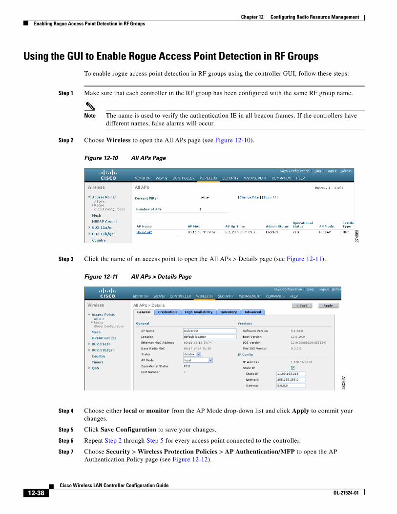
Chapter 12 Configuring Radio Resource ManagementEnabling Rogue Access Point Detection in RF Groups
Using the GUI to Enable Rogue Access Point Detection in RF GroupsTo enable rogue access point detection in RF groups using the controller GUI, follow these steps:
Step 1 Make sure that each controller in the RF group has been configured with the same RF group name.
Note The name is used to verify the authentication IE in all beacon frames. If the controllers have different names, false alarms will occur.
Step 2 Choose Wireless to open the All APs page (see Figure 12-10).
Figure 12-10 All APs Page
Step 3 Click the name of an access point to open the All APs > Details page (see Figure 12-11).
Figure 12-11 All APs > Details Page
Step 4 Choose either local or monitor from the AP Mode drop-down list and click Apply to commit your changes.
Step 5 Click Save Configuration to save your changes.
Step 6 Repeat Step 2 through Step 5 for every access point connected to the controller.
Step 7 Choose Security > Wireless Protection Policies > AP Authentication/MFP to open the AP Authentication Policy page (see Figure 12-12).
12-38Cisco Wireless LAN Controller Configuration Guide
OL-21524-01
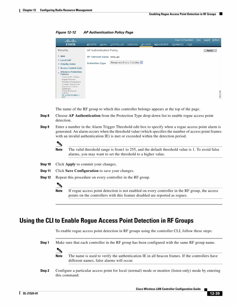
Chapter 12 Configuring Radio Resource ManagementEnabling Rogue Access Point Detection in RF Groups
Figure 12-12 AP Authentication Policy Page
The name of the RF group to which this controller belongs appears at the top of the page.
Step 8 Choose AP Authentication from the Protection Type drop-down list to enable rogue access point detection.
Step 9 Enter a number in the Alarm Trigger Threshold edit box to specify when a rogue access point alarm is generated. An alarm occurs when the threshold value (which specifies the number of access point frames with an invalid authentication IE) is met or exceeded within the detection period.
Note The valid threshold range is from1 to 255, and the default threshold value is 1. To avoid false alarms, you may want to set the threshold to a higher value.
Step 10 Click Apply to commit your changes.
Step 11 Click Save Configuration to save your changes.
Step 12 Repeat this procedure on every controller in the RF group.
Note If rogue access point detection is not enabled on every controller in the RF group, the access points on the controllers with this feature disabled are reported as rogues.
Using the CLI to Enable Rogue Access Point Detection in RF GroupsTo enable rogue access point detection in RF groups using the controller CLI, follow these steps:
Step 1 Make sure that each controller in the RF group has been configured with the same RF group name.
Note The name is used to verify the authentication IE in all beacon frames. If the controllers have different names, false alarms will occur.
Step 2 Configure a particular access point for local (normal) mode or monitor (listen-only) mode by entering this command:
12-39Cisco Wireless LAN Controller Configuration Guide
OL-21524-01
Chapter 12 Configuring Radio Resource ManagementEnabling Rogue Access Point Detection in RF Groups
config ap mode local Cisco_AP or config ap mode monitor Cisco_AP
Step 3 Save your changes by entering this command:
save config
Step 4 Repeat Step 2 and Step 3 for every access point connected to the controller.
Step 5 Enable rogue access point detection by entering this command:
config wps ap-authentication
Step 6 Specify when a rogue access point alarm is generated by entering this command. An alarm occurs when the threshold value (which specifies the number of access point frames with an invalid authentication IE) is met or exceeded within the detection period.
config wps ap-authentication threshold
Note The valid threshold range is from 1 to 255, and the default threshold value is 1. To avoid false alarms, you may want to set the threshold to a higher value.
Step 7 Save your changes by entering this command:
save config
Step 8 Repeat Step 5 through Step 7 on every controller in the RF group.
Note If rogue access point detection is not enabled on every controller in the RF group, the access points on the controllers with this feature disabled are reported as rogues.
Configuring ClientLinkClientLink is a spatial-filtering mechanism used at a transmitter to improve the received signal power or signal-to-noise (SNR) ratio at an intended receiver (client).
Cisco Aironet 1140, 1250, 1260, and 3500 series access points support ClientLink. ClientLink uses multiple transmit antennas to focus transmissions in the direction of an 802.11a or 802.11g client, which increases the downlink SNR and the data rate to the client, reduces coverage holes, and enhances overall system performance. ClientLink works with all existing 802.11a and 802.11g clients.
ClientLink starts only when the signal from the client falls below these thresholds:
• 802.11a clients—RSSI of –60 dBm or weaker
• 802.11g clients—RSSI of –50 dBm or weaker
Note 802.11b clients do not support ClientLink.
The access point actively maintains ClientLink data for up to 15 clients per radio.
In the receive data path, the access point updates the ClientLink data (the transmit steering matrix) for the active entries when packets are received from an address that matches an active entry. If a packet is received from a ClientLink client that is not an active entry, the access point automatically replaces the oldest active entry.
12-40Cisco Wireless LAN Controller Configuration Guide
OL-21524-01
Chapter 12 Configuring Radio Resource ManagementEnabling Rogue Access Point Detection in RF Groups
In the transmit data path, if the packet is destined for an active entry, the access point links the packets based on the recorded ClientLink data.
Guidelines for Using ClientLinkFollow these guidelines for using ClientLink:
• ClientLink is supported only for legacy orthogonal frequency-division multiplexing (OFDM) data rates (6, 9, 12, 18, 24, 36, 48, and 54 Mbps).
Note ClientLink is not supported for complementary code keying (CCK) data rates (1, 2, 5.5, and 11 Mbps).
• Only access points that support 802.11n (currently the 1140 and 1250 series access points) can use ClientLink.
• Two or more antennas must be enabled for transmission.
• All three antennas must be enabled for reception.
• OFDM data rates must be enabled.
• ClientLink must be enabled.
Note If the antenna configuration restricts operation to a single transmit antenna or if OFDM data rates are disabled, ClientLink is not used.
Using the GUI to Configure ClientLinkTo configure ClientLink using the controller GUI, follow these steps:
Step 1 Disable the 802.11a or 802.11b/g network as follows:
a. Choose Wireless > 802.11a/n or 802.11b/g/n > Network to open the 802.11a (or 802.11b/g) Global Parameters page.
b. Unselect the 802.11a (or 802.11b/g) Network Status check box.
c. Click Apply to commit your changes.
Step 2 Select the ClientLink check box to globally enable ClientLink on your 802.11a or 802.11g network, or leave it unselected to disable this feature. The default value is disabled.
Step 3 Reenable the network by selecting the 802.11a (or 802.11b/g) Network Status check box.
Step 4 Click Apply to commit your changes.
Step 5 Click Save Configuration to save your changes.
Note After you enable ClientLink on the network, it is automatically enabled for all the radios applicable to that network type.
12-41Cisco Wireless LAN Controller Configuration Guide
OL-21524-01
Chapter 12 Configuring Radio Resource ManagementEnabling Rogue Access Point Detection in RF Groups
Step 6 Override the global configuration and enable or disable ClientLink for a specific access point as follows:
a. Choose Wireless > Access Points > Radios > 802.11a/n or 802.11b/g/n to open the 802.11a/n (or 802.11b/g/n) Radios page.
b. Hover your cursor over the blue drop-down arrow for the access point for which you want to modify the radio configuration and choose Configure. The 802.11a/n (or 802.11b/g/n) Cisco APs > Configure page appears.
Step 7 In the 11n Parameters section, select the ClientLink check box to enable ClientLink for this access point or leave it unselected to disable this feature. The default value is unselected if ClientLink is disabled on the network and selected if ClientLink is enabled on the network.
Note If the access point does not support 802.11n, the ClientLink option is not available.
Step 8 Click Apply to commit your changes.
Step 9 Click Save Configuration to save your changes.
Using the CLI to Configure ClientLinkTo configure ClientLink using the controller CLI, follow these steps:
Step 1 Disable the 802.11a or 802.11b/g network by entering this command:
config {802.11a | 802.11b} disable network
Step 2 Globally enable or disable ClientLink on your 802.11a or 802.11g network by entering this command:
config {802.11a | 802.11b} beamforming global {enable | disable}
The default value is disabled.
Note After you enable ClientLink on the network, it is automatically enabled for all the radios applicable to that network type.
Step 3 Override the global configuration and enable or disable ClientLink for a specific access point by entering this command:
config {802.11a | 802.11b} beamforming ap Cisco_AP {enable | disable}
The default value is disabled if ClientLink is disabled on the network and enabled if ClientLink is enabled on the network.
Step 4 Reenable the network by entering this command:
config {802.11a | 802.11b} enable network
Step 5 Save your changes by entering this command:
save config
Step 6 See the ClientLink status for your network by entering this command:
show {802.11a | 802.11b}
Information similar to the following appears:
12-42Cisco Wireless LAN Controller Configuration Guide
OL-21524-01
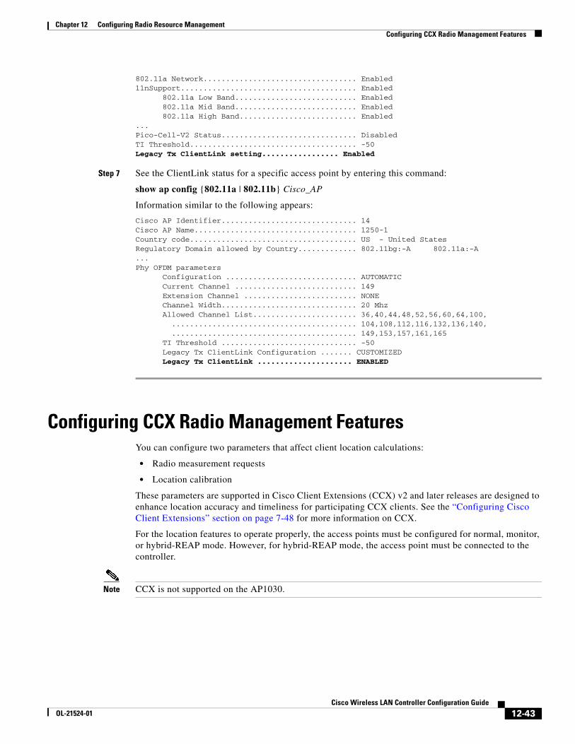
Chapter 12 Configuring Radio Resource ManagementConfiguring CCX Radio Management Features
802.11a Network.................................. Enabled11nSupport....................................... Enabled 802.11a Low Band........................... Enabled 802.11a Mid Band........................... Enabled 802.11a High Band.......................... Enabled...Pico-Cell-V2 Status.............................. DisabledTI Threshold..................................... -50Legacy Tx ClientLink setting................. Enabled
Step 7 See the ClientLink status for a specific access point by entering this command:
show ap config {802.11a | 802.11b} Cisco_AP
Information similar to the following appears:
Cisco AP Identifier.............................. 14Cisco AP Name.................................... 1250-1Country code..................................... US - United StatesRegulatory Domain allowed by Country............. 802.11bg:-A 802.11a:-A...Phy OFDM parameters Configuration ............................. AUTOMATIC Current Channel ........................... 149 Extension Channel ......................... NONE Channel Width.............................. 20 Mhz Allowed Channel List....................... 36,40,44,48,52,56,60,64,100, ......................................... 104,108,112,116,132,136,140, ......................................... 149,153,157,161,165 TI Threshold .............................. -50 Legacy Tx ClientLink Configuration ....... CUSTOMIZED
Legacy Tx ClientLink ..................... ENABLED
Configuring CCX Radio Management FeaturesYou can configure two parameters that affect client location calculations:
• Radio measurement requests
• Location calibration
These parameters are supported in Cisco Client Extensions (CCX) v2 and later releases are designed to enhance location accuracy and timeliness for participating CCX clients. See the “Configuring Cisco Client Extensions” section on page 7-48 for more information on CCX.
For the location features to operate properly, the access points must be configured for normal, monitor, or hybrid-REAP mode. However, for hybrid-REAP mode, the access point must be connected to the controller.
Note CCX is not supported on the AP1030.
12-43Cisco Wireless LAN Controller Configuration Guide
OL-21524-01
Chapter 12 Configuring Radio Resource ManagementConfiguring CCX Radio Management Features
Radio Measurement RequestsWhen you enable the radio measurements requests feature, lightweight access points issue broadcast radio measurement request messages to clients running CCXv2 or later releases. The access points transmit these messages for every SSID over each enabled radio interface at a configured interval. In the process of performing 802.11 radio measurements, CCX clients send 802.11 broadcast probe requests on all the channels specified in the measurement request. The Cisco Location Appliance uses the uplink measurements based on these requests received at the access points to quickly and accurately calculate the client location. You do not need to specify on which channels the clients are to measure. The controller, access point, and client automatically determine which channels to use.
In controller software release 4.1 or later releases, the radio measurement feature has been expanded to enable the controller to also obtain information on the radio environment from the client’s perspective (rather than from just that of the access point). In this case, the access points issue unicast radio measurement requests to a particular CCXv4 or v5 client. The client then sends various measurement reports back to the access point and onto the controller. These reports include information about the radio environment and data used to interpret the location of the clients. To prevent the access points and controller from being overwhelmed by radio measurement requests and reports, only two clients per access point and up to 20 clients per controller are supported. You can view the status of radio measurement requests for a particular access point or client as well as radio measurement reports for a particular client from the controller CLI.
Controller software release 4.1 or later releases improve the ability of the Location Appliance to accurately interpret the location of a device through a CCXv4 feature called location-based services. The controller issues a path-loss request to a particular CCXv4 or v5 client. If the client chooses to respond, it sends a path-loss measurement report to the controller. These reports contain the channel and transmit power of the client.
Note Non-CCX and CCXv1 clients ignore the CCX measurement requests and do not participate in the radio measurement activity.
Location CalibrationFor CCX clients that need to be tracked more closely (for example, when a client calibration is performed), the controller can be configured to command the access point to send unicast measurement requests to these clients at a configured interval and whenever a CCX client roams to a new access point. These unicast requests can be sent out more often to these specific CCX clients than the broadcast measurement requests, which are sent to all clients. When location calibration is configured for non-CCX and CCXv1 clients, the clients are forced to disassociate at a specified interval to generate location measurements.
Using the GUI to Configure CCX Radio ManagementTo configure CCX radio management using the controller GUI, follow these steps:
Step 1 Choose Wireless > 802.11a/n or 802.11b/g/n > Network to open the 802.11a (or 802.11b/g) Global Parameters page (see Figure 12-13).
12-44Cisco Wireless LAN Controller Configuration Guide
OL-21524-01
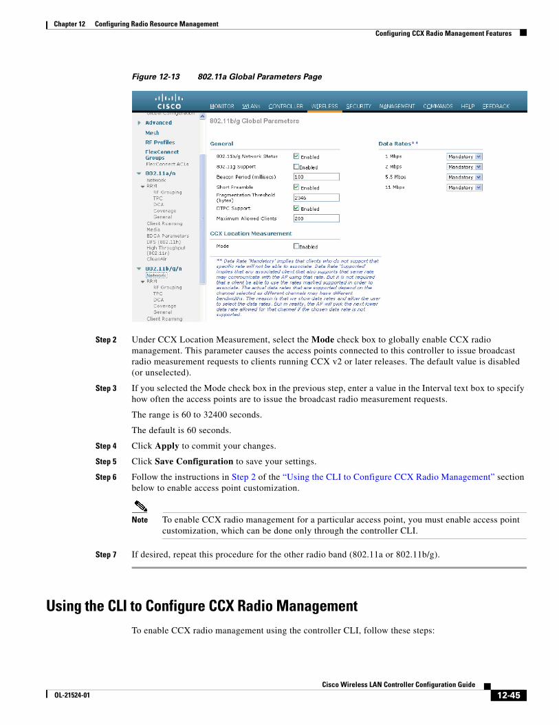
Chapter 12 Configuring Radio Resource ManagementConfiguring CCX Radio Management Features
Figure 12-13 802.11a Global Parameters Page
Step 2 Under CCX Location Measurement, select the Mode check box to globally enable CCX radio management. This parameter causes the access points connected to this controller to issue broadcast radio measurement requests to clients running CCX v2 or later releases. The default value is disabled (or unselected).
Step 3 If you selected the Mode check box in the previous step, enter a value in the Interval text box to specify how often the access points are to issue the broadcast radio measurement requests.
The range is 60 to 32400 seconds.
The default is 60 seconds.
Step 4 Click Apply to commit your changes.
Step 5 Click Save Configuration to save your settings.
Step 6 Follow the instructions in Step 2 of the “Using the CLI to Configure CCX Radio Management” section below to enable access point customization.
Note To enable CCX radio management for a particular access point, you must enable access point customization, which can be done only through the controller CLI.
Step 7 If desired, repeat this procedure for the other radio band (802.11a or 802.11b/g).
Using the CLI to Configure CCX Radio ManagementTo enable CCX radio management using the controller CLI, follow these steps:
12-45Cisco Wireless LAN Controller Configuration Guide
OL-21524-01
Chapter 12 Configuring Radio Resource ManagementConfiguring CCX Radio Management Features
Step 1 Globally enable CCX radio management by entering this command:
config advanced {802.11a | 802.11b} ccx location-meas global enable interval_seconds
The range for the interval_seconds parameter is 60 to 32400 seconds, and the default value is 60 seconds. This command causes all access points connected to this controller in the 802.11a or 802.11b/g network to issue broadcast radio measurement requests to clients running CCXv2 or later releases.
Step 2 Enable access point customization by entering these commands:
• config advanced {802.11a | 802.11b} ccx customize Cisco_AP {on | off}
This command enables or disables CCX radio management features for a particular access point in the 802.11a or 802.11b/g network.
• config advanced {802.11a | 802.11b} ccx location-meas ap Cisco_AP enable interval_seconds
The range for the interval_seconds parameter is 60 to 32400 seconds, and the default value is 60 seconds. This command causes a particular access point in the 802.11a or 802.11b/g network to issue broadcast radio measurement requests to clients running CCXv2 or higher.
Step 3 Enable or disable location calibration for a particular client by entering this command:
config client location-calibration {enable | disable} client _mac interval_seconds
Note You can configure up to five clients per controller for location calibration.
Step 4 Save your settings by entering this command:
save config
Using the CLI to Obtain CCX Radio Management InformationUse these commands to obtain information about CCX radio management on the controller:
• To see the CCX broadcast location measurement request configuration for all access points connected to this controller in the 802.11a or 802.11b/g network, enter this command:
show advanced {802.11a | 802.11b} ccx global
• To see the CCX broadcast location measurement request configuration for a particular access point in the 802.11a or 802.11b/g network, enter this command:
show advanced {802.11a | 802.11b} ccx ap Cisco_AP
• To see the status of radio measurement requests for a particular access point, enter this command:
show ap ccx rm Cisco_AP status
Information similar to the following appears:
A Radio
Beacon Request................................. Enabled Channel Load Request........................... Enabled Frame Request.................................. Disabled Noise Histogram Request........................ Disabled Path Loss Request.............................. Disabled Interval....................................... 60 Iteration...................................... 5
12-46Cisco Wireless LAN Controller Configuration Guide
OL-21524-01
Chapter 12 Configuring Radio Resource ManagementConfiguring CCX Radio Management Features
B Radio
Beacon Request................................. Disabled Channel Load Request........................... Enabled Frame Request.................................. Disabled Noise Histogram Request........................ Enabled Path Loss Request.............................. Disabled Interval....................................... 60 Iteration................................... 5
• To see the status of radio measurement requests for a particular client, enter this command:
show client ccx rm client_mac status
Information similar to the following appears:
Client Mac Address............................... 00:40:96:ae:53:b4Beacon Request................................... EnabledChannel Load Request............................. DisabledFrame Request.................................... DisabledNoise Histogram Request.......................... DisabledPath Loss Request................................ DisabledInterval......................................... 5Iteration........................................ 3
• To see radio measurement reports for a particular client, enter these commands:
• show client ccx rm client_mac report beacon—Shows the beacon report for the specified client.
• show client ccx rm client_mac report chan-load—Shows the channel-load report for the specified client.
12-47Cisco Wireless LAN Controller Configuration Guide
OL-21524-01
Chapter 12 Configuring Radio Resource ManagementConfiguring CCX Radio Management Features
• show client ccx rm client_mac report noise-hist—Shows the noise-histogram report for the specified client.
• show client ccx rm client_mac report frame—Shows the frame report for the specified client.
• To see the clients configured for location calibration, enter this command:
show client location-calibration summary
• To see the RSSI reported for both antennas on each access point that heard the client, enter this command:
show client detail client_mac
Using the CLI to Debug CCX Radio Management IssuesUse these commands if you experience any CCX radio management problems.
• To debug CCX broadcast measurement request activity, enter this command:
debug airewave-director message {enable | disable}
• To debug client location calibration activity, enter this command:
debug ccxrm [all | error | warning | message | packet | detail {enable | disable}]
• The CCX radio measurement report packets are encapsulated in Internet Access Point Protocol (IAPP) packets. Therefore, if the previous debug ccxrm command does not provide any debugs, enter this command to provide debugs at the IAPP level:
debug iapp error {enable | disable}
• To debug the output for forwarded probes and their included RSSI for both antennas, enter this command:
debug dot11 load-balancing
12-48Cisco Wireless LAN Controller Configuration Guide
OL-21524-01