Embed Size (px)
Citation preview
MCS13 Rev B 022420
Confined Space Personnel WinchUser Instruction Manual
This manual is intended to meet the Manufacturer’s Instructions as required by the American National Standards Institute (ANSI) Z359 and should be used as part of an employee training program as required by the Occupational
Safety and Health Administration (OSHA).
1306 S. Alameda Street, Compton, CA 90221, USA Tel: 800-719-4619 Fax: 323-752-5613

Table of Contents
1.0 Warnings and Important Information ..................................................................................
2.0 Description ..........................................................................................................................
3.0 Application ...........................................................................................................................
4.0 System Requirements ..........................................................................................................
5.0 Installation and Use ............................................................................................................. 6.0 Maintenance, Service, and Storage .....................................................................................
7.0 Inspection ............................................................................................................................
8.0 Labels ...................................................................................................................................
9.0 Definitions ...........................................................................................................................
Appendix A .........................................................................................................................
Appendix C .........................................................................................................................
3
4
4
5
6
10
10
13
14
16
17
For purposes of this manual, the FallTech® Confined Space Personnel Winch, in all iterations, may be referred to collectively as the personnel winch, the equipment, the product, or the unit.
Throughout this manual, ANSI Z359.0-2012 fall protection words, phases and terms are used. These terms are all formally defined in Section 9 of this manual.
2MCS13 Rev B 022420
1.0 Warnings and Important Information
This product is part of a personal fall arrest, restraint, work positioning, suspension, or rescue system. A Personal Fall Arrest System (PFAS) is typically composed of an anchorage and a Full Body Harness (FBH), with a connecting device, i.e., a Energy Absorbing Lanyard (EAL), or aSelf-Retracting Device (SRD), attached to the dorsal D-ring of the FBH.
These instructions must be provided to the worker using this equipment. The worker must read and understand the manufacturer’s instructions for each component or part of the complete system. Manufacturer’s instructions must be followed for proper use, care, and maintenance of this product. These instructions must be retained and be kept available for the worker’s reference at all times. Alterations or misuse of this product, or failure to follow instructions, may result in serious injury or death.
A Fall Protection Plan must be on file and available for review by all workers. It is the responsibility of the worker and the purchaser of this equipment to assure that users of this equipment are properly trained in its use, maintenance, and storage. Training must be repeated at regular intervals. Training must not subject the trainee to fall hazards.
Consult a doctor if there is reason to doubt your fitness to safely absorb the shock of a fall event. Age and fitness seriously affect a worker’s ability to withstand falls. Pregnant women or minors must not use this equipment.
ANSI limits the weight of fall protection equipment users to a maximum of 310 lbs. Products in this manual may have a rated capacity exceeding ANSI capacity limits. Heavy users experience more risk of serious injury or death due to falls because of increased fall arrest forces placed on the user’s body. In addition, the onset of suspension trauma after a fall even may be accelerated for heavy users.
The user of the equipment discussed in this manual must read and understand the entire manual before beginning work.
NOTE: For more information consult the ANSI Z359 body of standards.
• Avoid moving machinery, thermal, electrical, and/or chemical hazards as contact may cause serious injury or death.• Avoid swing falls. • Follow the weight restrictions and recommendations in this manual. • Remove from service any equipment subjected to fall arrest forces.• Remove from service any equipment that fails inspection.• Do not alter or intentionally misuse this equipment.• Consult FallTech when using this equipment in combination with components or subsystems other than those described in this manual.• Do not connect rebar hooks, large carabiners, or large snap hooks to the FBH dorsal D-rings as this may cause a roll-out condition and/or
unintentional disengagement.• Avoid sharp and/or abrasive surfaces and edges. • Use caution when performing arc welding. Arc flash from arc welding operations, including accidental arcs from electrical equipment, can
damage equipment and are potentially fatal. • Examine the work area. Be aware of the surroundings and workplace hazards that may impact safety, security, and the functioning of fall arrest
systems and components. • Hazards may include but not be limited to cable or debris tripping hazards, equipment failures, personnel mistakes, moving equipment such as
carts, barrows, fork lifts, cranes, or dollies. Do not allow materials, tools or equipment in transit to contact any part of the fall arrest system. • Do not work under suspended loads.
WARNING
IMPORTANT
3MCS13 Rev B 022420
The FallTech® Confined Space Personnel Winch is primarily for those entering and working in confined spaces, both permit and non-permit, and isto be used as part of a restraint, work positioning, suspension, or rescue system in a complete confined space system. See Section 3 and AppendixC of this manual.
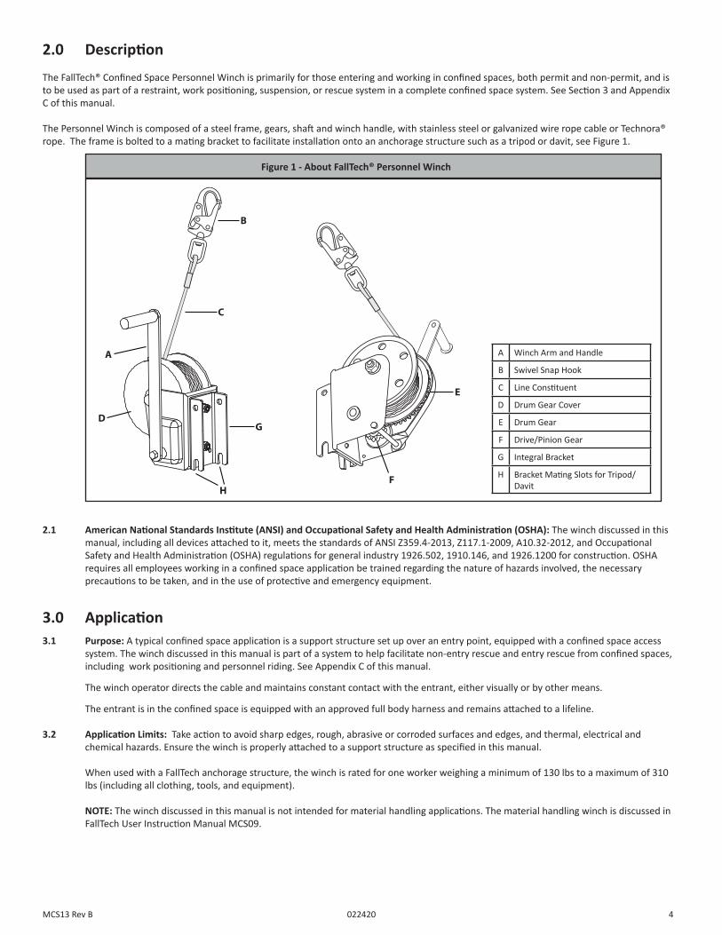
The Personnel Winch is composed of a steel frame, gears, shaft and winch handle, with stainless steel or galvanized wire rope cable or Technora® rope. The frame is bolted to a mating bracket to facilitate installation onto an anchorage structure such as a tripod or davit, see Figure 1.
2.0 Description
2.1 American National Standards Institute (ANSI) and Occupational Safety and Health Administration (OSHA): The winch discussed in this manual, including all devices attached to it, meets the standards of ANSI Z359.4-2013, Z117.1-2009, A10.32-2012, and Occupational Safety and Health Administration (OSHA) regulations for general industry 1926.502, 1910.146, and 1926.1200 for construction. OSHA requires all employees working in a confined space application be trained regarding the nature of hazards involved, the necessary precautions to be taken, and in the use of protective and emergency equipment.
Figure 1 - About FallTech® Personnel Winch
A
D
B
C
G
E
FH
A Winch Arm and Handle
B Swivel Snap Hook
C Line Constituent
D Drum Gear Cover
E Drum Gear
F Drive/Pinion Gear
G Integral Bracket
H Bracket Mating Slots for Tripod/Davit
3.0 Application3.1 Purpose: A typical confined space application is a support structure set up over an entry point, equipped with a confined space access system. The winch discussed in this manual is part of a system to help facilitate non-entry rescue and entry rescue from confined spaces, including work positioning and personnel riding. See Appendix C of this manual.
The winch operator directs the cable and maintains constant contact with the entrant, either visually or by other means.
The entrant is in the confined space is equipped with an approved full body harness and remains attached to a lifeline.
3.2 Application Limits: Take action to avoid sharp edges, rough, abrasive or corroded surfaces and edges, and thermal, electrical and chemical hazards. Ensure the winch is properly attached to a support structure as specified in this manual.
When used with a FallTech anchorage structure, the winch is rated for one worker weighing a minimum of 130 lbs to a maximum of 310 lbs (including all clothing, tools, and equipment).
NOTE: The winch discussed in this manual is not intended for material handling applications. The material handling winch is discussed in FallTech User Instruction Manual MCS09.
4MCS13 Rev B 022420
4.1 Capacity: The capacity of the winch is one worker between 130 lbs to 310 lbs. (140 kg) including tools, clothing, etc.
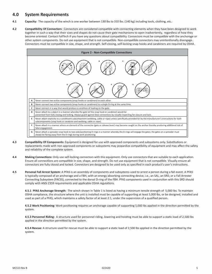
4.2 Compatibility Of Connectors: Connectors are considered compatible with connecting elements when they have been designed to work together in such a way that their sizes and shapes do not cause their gate mechanisms to open inadvertently, regardless of how they become oriented. Contact FallTech if you have any questions about compatibility. Connectors must be compatible with the anchorage or other system components. Do not use equipment that is not compatible. Non-compatible connectors may unintentionally disengage. Connectors must be compatible in size, shape, and strength. Self-closing, self-locking snap hooks and carabiners are required by OSHA.
4.0 System Requirements
4.3 Compatibility Of Components: Equipment is designed for use with approved components and subsystems only. Substitutions or replacements made with non-approved components or subsystems may jeopardize compatibility of equipment and may affect the safety and reliability of the complete system.
4.4 Making Connections: Only use self-locking connectors with this equipment. Only use connectors that are suitable to each application. Ensure all connections are compatible in size, shape, and strength. Do not use equipment that is not compatible. Visually ensure all connectors are fully closed and locked. Connectors are designed to be used only as specified in each product’s user’s instructions.
4.5 Personal Fall Arrest System: A PFAS is an assembly of components and subsystems used to arrest a person during a fall event. A PFAS is typically composed of an anchorage and a FBH, with an energy absorbing connecting device, i.e., an SAL, an SRD, or a Fall Arrester Connecting Subsystem (FACSS), connected to the dorsal D-ring of the FBH. PFAS components used in conjunction with this SRD should comply with ANSI Z359 requirements and applicable OSHA regulations.
4.5.1 PFAS Anchorage Strength: The winch shown in Table 1 is listed as having a minimum tensile strength of 5,000 lbs. To maintain OSHA compliance, the structure where the unit is installed must be capable of supporting at least 5,000 lbs, or be designed, installed and used as part of a PFAS, which maintains a safety factor of at least 2:1, under the supervision of a qualified person.
4.5.2 Work Positioning: Work positioning requires an anchorage capable of supporting 5,000 lbs applied in the direction permitted by the system.
4.5.3 Personnel Riding: A structure used for personnel riding, lowering and hoisting must be able to support a static load of 2,500 lbs applied in the direction permitted by the system.
4.5.4 Rescue: A structure used for rescue must be able to support a static load of 2,500 lbs applied in the direction permitted by the system.
A Never connect two active components (snap hooks or carabiners) to each other.
B Never connect two active components (snap hooks or carabiners) to a single D-ring at the same time.
C Never connect in a way that would produce a condition of loading on the gate.
D Never attach to a object in a manner whereby the gate (of the snap hook or carabiner) would be prevented from fully closing and locking. Always guard against false connections by visually inspecting for closure and lock.
E Never attach explicitly to a constituent subcomponent (webbing, cable or rope) unless specifically provided for by the manufacturer’s instructions for both subcomponents (snap hook or carabiner and webbing, cable or rope).
F Never attach in a manner where an element of the connector (gate or release lever) may become caught on the anchor thereby producing additional risk of false engagement.
G Never attach a spreader snap hook to two side/positioning D-rings in a manner whereby the D-rings will engage the gates; the gates on a spreader must always be facing away from the D-rings during work positioning.
Figure 2 - Non-Compatible Connections
5MCS13 Rev B 022420
5.0 Installation and Use5.1 General Installation Requirements: The winch is designed as a part of a confined space system. The user must perform specific job hazard analysis in accordance with OSHA regulations. Mitigate hazards in accordance with OSHA guidelines.
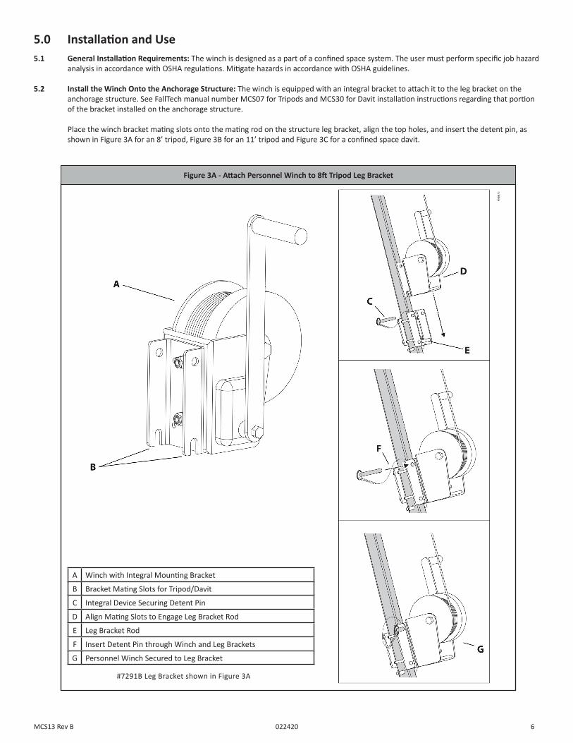
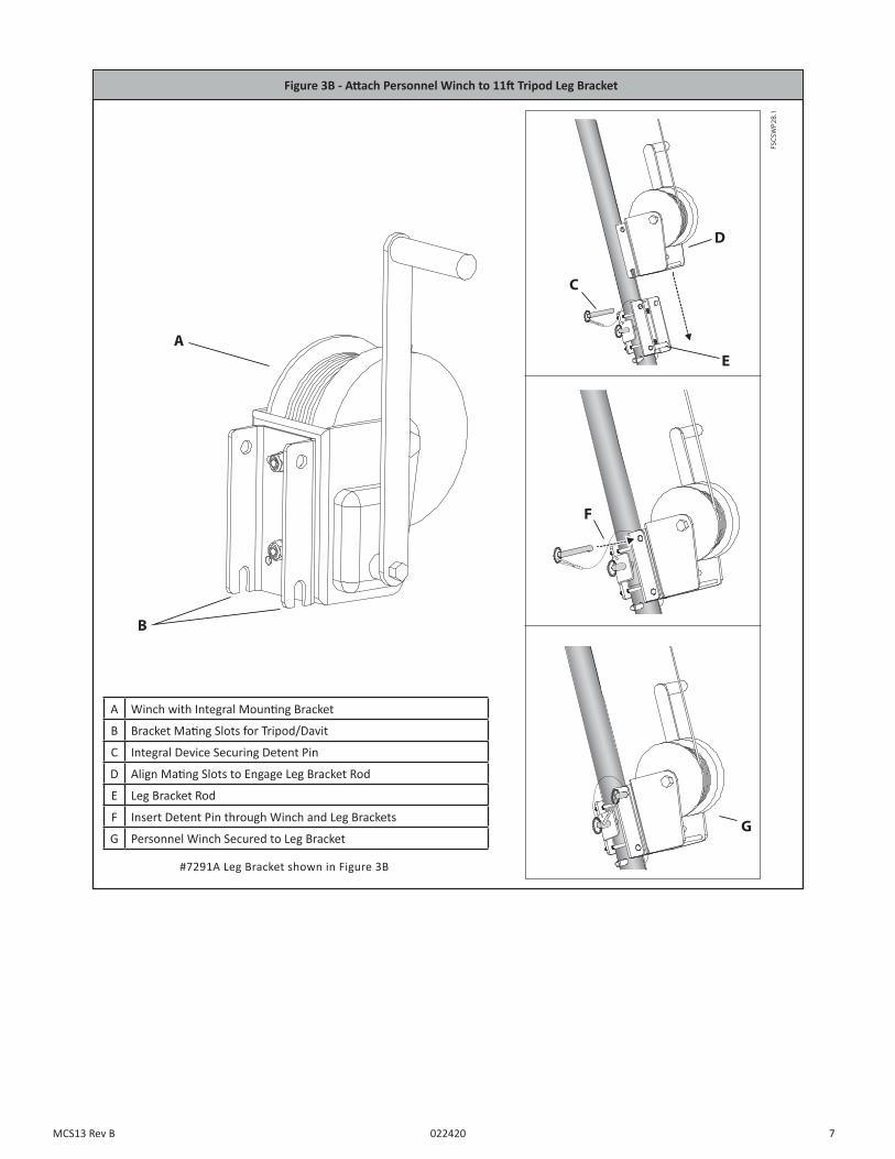
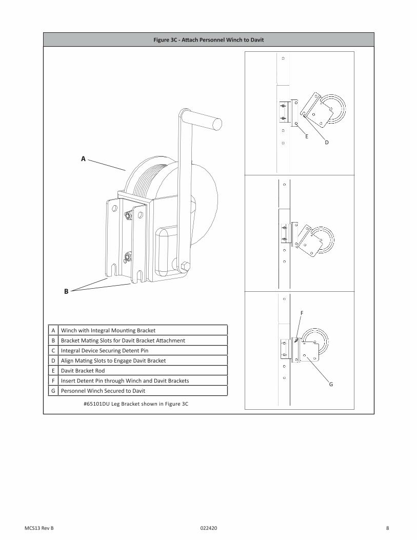
5.2 Install the Winch Onto the Anchorage Structure: The winch is equipped with an integral bracket to attach it to the leg bracket on the anchorage structure. See FallTech manual number MCS07 for Tripods and MCS30 for Davit installation instructions regarding that portion of the bracket installed on the anchorage structure.
Place the winch bracket mating slots onto the mating rod on the structure leg bracket, align the top holes, and insert the detent pin, as shown in Figure 3A for an 8’ tripod, Figure 3B for an 11’ tripod and Figure 3C for a confined space davit.
Figure 3A - Attach Personnel Winch to 8ft Tripod Leg Bracket
A Winch with Integral Mounting Bracket
B Bracket Mating Slots for Tripod/Davit
C Integral Device Securing Detent Pin
D Align Mating Slots to Engage Leg Bracket Rod
E Leg Bracket Rod
F Insert Detent Pin through Winch and Leg Brackets
G Personnel Winch Secured to Leg Bracket
#7291B Leg Bracket shown in Figure 3A
6MCS13 Rev B 022420
FSCSW
P2B.1
060915
C
D
A
B
E
F
G
Figure 3B - Attach Personnel Winch to 11ft Tripod Leg Bracket
A Winch with Integral Mounting Bracket
B Bracket Mating Slots for Tripod/Davit
C Integral Device Securing Detent Pin
D Align Mating Slots to Engage Leg Bracket Rod
E Leg Bracket Rod
F Insert Detent Pin through Winch and Leg Brackets
G Personnel Winch Secured to Leg Bracket
#7291A Leg Bracket shown in Figure 3B
7MCS13 Rev B 022420
FSCSW
P2B.1
060915
C
D
A
B
E
F
G
Figure 3C - Attach Personnel Winch to Davit
A Winch with Integral Mounting Bracket
B Bracket Mating Slots for Davit Bracket Attachment
C Integral Device Securing Detent Pin
D Align Mating Slots to Engage Davit Bracket
E Davit Bracket Rod
F Insert Detent Pin through Winch and Davit Brackets
G Personnel Winch Secured to Davit
#65101DU Leg Bracket shown in Figure 3C
ED
F
G
8MCS13 Rev B 022420
5.3 Use of the Winch: Inspect the winch and line constituent before each use in accordance with the procedures in Section 7 of this manual. Ensure the cable or rope are in proper working order, with no damage or deformities. See Section 7 for inspection criteria. Ensure the support structure is configured for maximum efficiency, and correctly oriented. The device should be at a comfortable height for use. Adjust device bracket if necessary. For more information see instruction manuals MCS07 for tripods or MCS30 for the davit.
Attach the winch leg end connector to the entrant’s dorsal D-ring of the full body harness.
To raise a load, rotate the winch handle in the clockwise direction.
To suspend a load, release the handle and the brake will suspend the load until further action is needed. Do not exceed the rated capacity of 310lbs.
To lower a load, rotate the crank handle counterclockwise to lower the entrant into a confined space. The handle will rotate approximately one revolution before the load starts to lower. If the secondary brake is engaged, raise the load approximately one turn of the drum before attempting to lower the load.
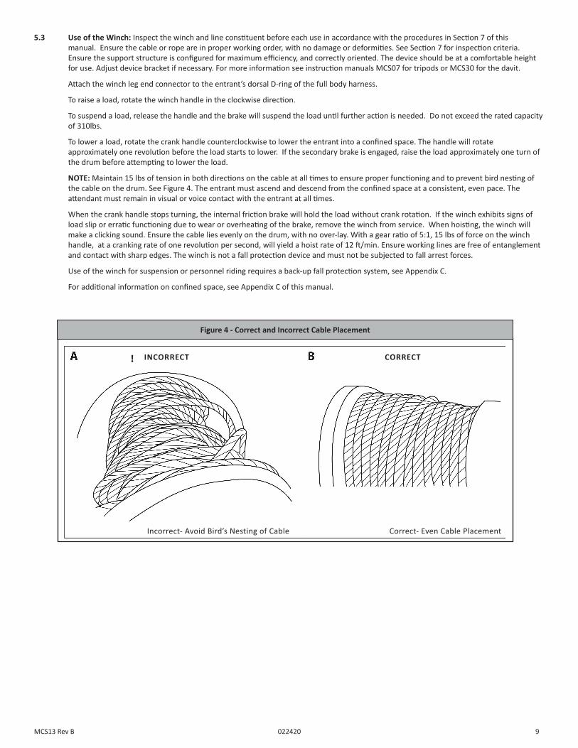
NOTE: Maintain 15 lbs of tension in both directions on the cable at all times to ensure proper functioning and to prevent bird nesting of the cable on the drum. See Figure 4. The entrant must ascend and descend from the confined space at a consistent, even pace. The attendant must remain in visual or voice contact with the entrant at all times.
When the crank handle stops turning, the internal friction brake will hold the load without crank rotation. If the winch exhibits signs of load slip or erratic functioning due to wear or overheating of the brake, remove the winch from service. When hoisting, the winch will make a clicking sound. Ensure the cable lies evenly on the drum, with no over-lay. With a gear ratio of 5:1, 15 lbs of force on the winch handle, at a cranking rate of one revolution per second, will yield a hoist rate of 12 ft/min. Ensure working lines are free of entanglement and contact with sharp edges. The winch is not a fall protection device and must not be subjected to fall arrest forces.
Use of the winch for suspension or personnel riding requires a back-up fall protection system, see Appendix C.
For additional information on confined space, see Appendix C of this manual.
CORRECTINCORRECT
Figure 4 - Correct and Incorrect Cable Placement
Incorrect- Avoid Bird’s Nesting of Cable Correct- Even Cable Placement
9MCS13 Rev B 022420
6.0 Maintenance, Service, and Storage6.1 Maintenance: Ensure the winch is kept free of excess paint, grease, dirt, or other contaminants. Clean the exterior of the unit as required with a detergent/water solution. Do not allow water other corrosion causing elements to enter the gears. After cleaning, pull the lifeline all the way out, allow the unit to air dry, then rewind the lifeline into the unit.
Apply a thin coat of number 2 lithium grease to the winch gears occasionally.
DO NOT use heat to dry. DO NOT attempt to disassemble the winch.
6.2 Service: If service is required for any reason; inspection failure, or any type of malfunction, tag the unit as “UNUSABLE”, store separately, and contact FallTech at 323-752-0066 to receive a Return Authorization number or to locate the nearest FallTech Service Center. The winch is not user repairable. Only the manufacturer, or a repair facility authorized in writing, may make repairs to the winch. 6.3 Storage: Store the winch in a cool, dry, clean environment out of direct sunlight. Avoid exposure to chemical or caustic vapors. Thoroughly inspect the winch after any period of extended storage.
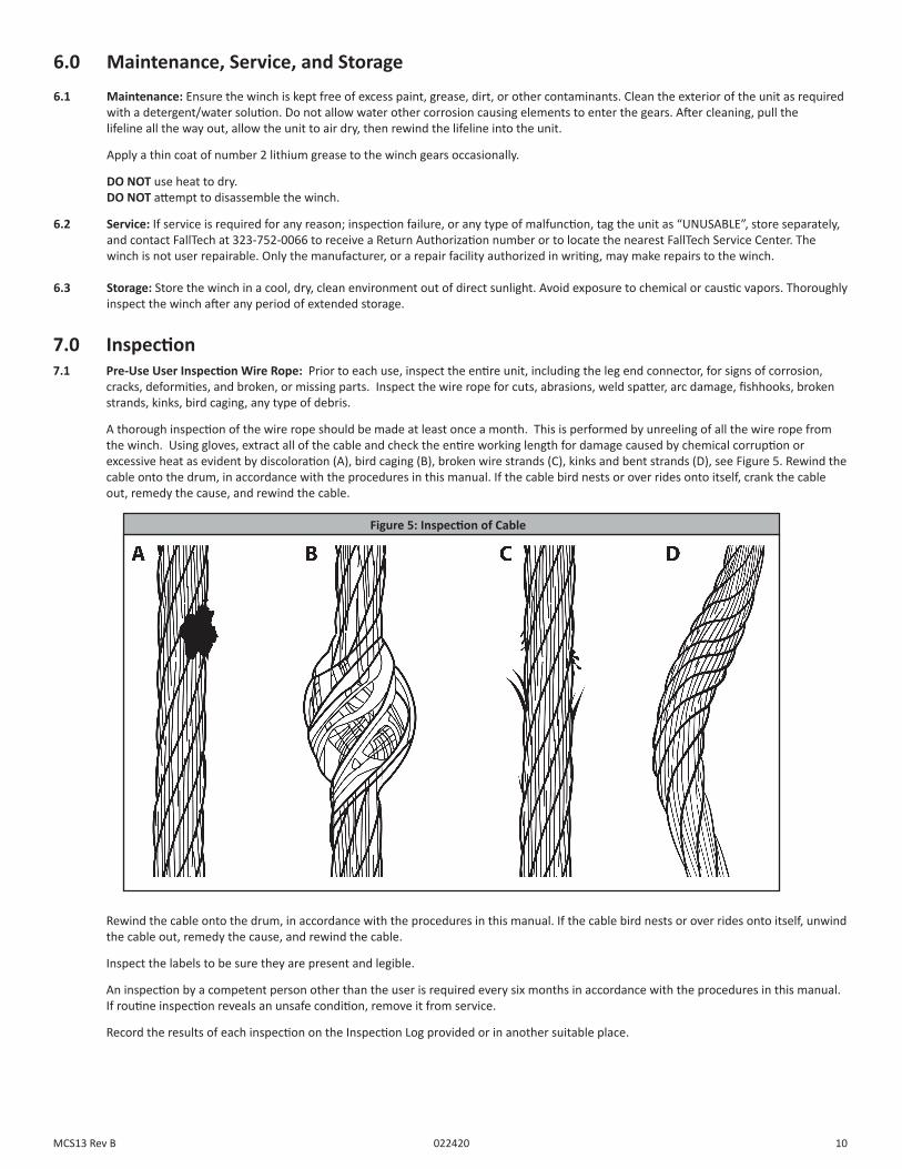
7.0 Inspection7.1 Pre-Use User Inspection Wire Rope: Prior to each use, inspect the entire unit, including the leg end connector, for signs of corrosion, cracks, deformities, and broken, or missing parts. Inspect the wire rope for cuts, abrasions, weld spatter, arc damage, fishhooks, broken strands, kinks, bird caging, any type of debris.
A thorough inspection of the wire rope should be made at least once a month. This is performed by unreeling of all the wire rope from the winch. Using gloves, extract all of the cable and check the entire working length for damage caused by chemical corruption or excessive heat as evident by discoloration (A), bird caging (B), broken wire strands (C), kinks and bent strands (D), see Figure 5. Rewind the cable onto the drum, in accordance with the procedures in this manual. If the cable bird nests or over rides onto itself, crank the cable out, remedy the cause, and rewind the cable.
Figure 5: Inspection of Cable
Rewind the cable onto the drum, in accordance with the procedures in this manual. If the cable bird nests or over rides onto itself, unwind the cable out, remedy the cause, and rewind the cable.
Inspect the labels to be sure they are present and legible.
An inspection by a competent person other than the user is required every six months in accordance with the procedures in this manual. If routine inspection reveals an unsafe condition, remove it from service.
Record the results of each inspection on the Inspection Log provided or in another suitable place.
10MCS13 Rev B 022420
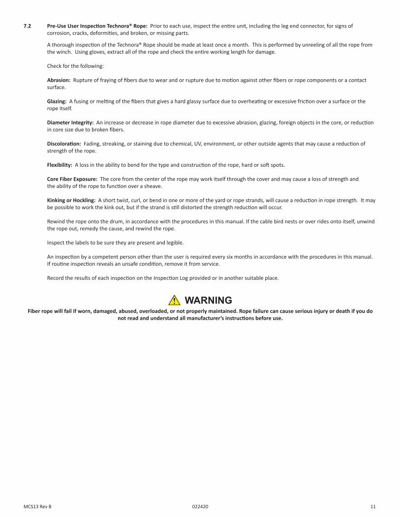
7.2 Pre-Use User Inspection Technora® Rope: Prior to each use, inspect the entire unit, including the leg end connector, for signs of corrosion, cracks, deformities, and broken, or missing parts.
A thorough inspection of the Technora® Rope should be made at least once a month. This is performed by unreeling of all the rope from the winch. Using gloves, extract all of the rope and check the entire working length for damage.
Check for the following:
Abrasion: Rupture of fraying of fibers due to wear and or rupture due to motion against other fibers or rope components or a contact surface.
Glazing: A fusing or melting of the fibers that gives a hard glassy surface due to overheating or excessive friction over a surface or the rope itself.
Diameter Integrity: An increase or decrease in rope diameter due to excessive abrasion, glazing, foreign objects in the core, or reduction in core size due to broken fibers.
Discoloration: Fading, streaking, or staining due to chemical, UV, environment, or other outside agents that may cause a reduction of strength of the rope.
Flexibility: A loss in the ability to bend for the type and construction of the rope, hard or soft spots.
Core Fiber Exposure: The core from the center of the rope may work itself through the cover and may cause a loss of strength and the ability of the rope to function over a sheave.
Kinking or Hockling: A short twist, curl, or bend in one or more of the yard or rope strands, will cause a reduction in rope strength. It may be possible to work the kink out, but if the strand is still distorted the strength reduction will occur.
Rewind the rope onto the drum, in accordance with the procedures in this manual. If the cable bird nests or over rides onto itself, unwind the rope out, remedy the cause, and rewind the rope.
Inspect the labels to be sure they are present and legible.
An inspection by a competent person other than the user is required every six months in accordance with the procedures in this manual. If routine inspection reveals an unsafe condition, remove it from service.
Record the results of each inspection on the Inspection Log provided or in another suitable place.
WARNINGFiber rope will fail if worn, damaged, abused, overloaded, or not properly maintained. Rope failure can cause serious injury or death if you do
not read and understand all manufacturer’s instructions before use.
11MCS13 Rev B 022420

Inspection RecordModel #:_________________________ Serial #:_________________________ Date of Manufacture:_________________________
INSPECTION DATE INSPECTOR COMMENTS PASS/FAIL CORRECTIVE ACTION NEEDED APPROVED BY
7.3 Inspection Document: Record inspection results on the Inspection Record provided on the following page or on a similar document.
12MCS13 Rev B 022420
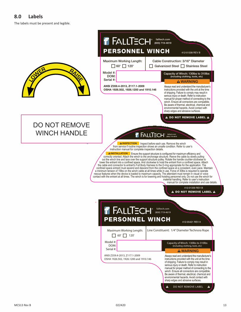
8.0 LabelsThe labels must be present and legible.
1 2 3 4 5 6 7 8
87654321
A
B
C
D
E
F
A
B
C
D
E
F
REV
TITLE
ITEM NO.
SIZESHEETSCALE
Label, Personnel WinchLabel 1
412-01338
REVISIONSREV DRAWNDATE
A PRELIMINARY INITIAL RELEASEDESCRIPTION
THE INFORMATION EMBODIED IN THIS DOCUMENT IS STRICTLY CONFIDENTIAL AND ARE SUPPLIED WITH THE UNDERSTANDING THAT THEY WILL NOT BE DISCLOSED TO THIRD PARTIES
1:1 1/1 A B
GENERAL NOTES:1.2.3.4. WEIGHT (FOR REFERENCE ONLY)
N/A
N/A
N/A
Ed Gabrielyan
N/A
N/A
N/A
Poly Carbonate Coated Vinyl
APPLICABLE STANDARDS:ASME Y14.5-2009 & DIN ISO 2768EXCEPTION: TRAILING ZEROS DENOTE TOLERANCE
UNLESS OTHERWISE SPECIFIED DIMENSIONS ARE IN MILLIMETERS (mm)
TOLERANCES ARE:0 to 6 ...........................................6 to 30 .........................................30 to 120 .....................................120 + ...........................................ANGLES ......................................
APPROVED
MFG
CHECKED
SURFACE ROUGHNESS
SURFACE FINISH
12/26/18MATERIALCOLORS DRAWN
N/A
N/A
N/A
0.10.20.30.50.5
PANTONE BLACK C
PANTONE 5415 C
PANTONE 144 C
Editable*Actual Size*
Outlined*Actual Size*
DIELINE
CUTOUT LOCATION DIMS
MAIN DIELINE DIMS
DO NOT PRINT
DO NOT REMOVE LABEL
Always read and understand the manufacturer’s instructions provided with the unit at the timeof shipping. Failure to comply may result in serious injury or death. Refer to instruction manual for proper method of connecting to the winch. Ensure all connectors are compatible. Be aware of thermal, electrical, chemical and environmental hazards. Avoid contact with sharp edges and abrasive surfaces.
PERSONNEL WINCH 412-01338 REV B
Model #:DOM:
Serial #:
Maximum Working Length:
60' 120'
Cable Construction: 3/16" Diameter
Galvanized Steel Stainless Steel
ANSI Z359.4-2013, Z117.1-2009OSHA 1926.502, 1926.1200 and 1910.146
Capacity of Winch: 130lbs to 310lbs(including clothing, tools, etc)
falltech.com
(800) 719-4619
A PRELIMINARY INITIAL RELEASE 09/12/17 SAMB UPDATED ARTWORK 01/21/19 ED
100mm
80mm
14.5mm
10.5mm
40mm x 10mm CUTOUT
1 2 3 4 5 6 7 8
87654321
A
B
C
D
E
F
A
B
C
D
E
F
REV
TITLE
ITEM NO.
SIZESHEETSCALE
Label, Personnel WinchLabel 2
412-01339
REVISIONSTHE INFORMATION EMBODIED IN THIS DOCUMENT IS STRICTLY CONFIDENTIAL AND ARE SUPPLIED WITH THE UNDERSTANDING THAT THEY WILL NOT BE DISCLOSED TO THIRD PARTIES
1:1 1/1 A B
GENERAL NOTES:1.2.3.4. WEIGHT (FOR REFERENCE ONLY)
N/A
N/A
N/A
Ed Gabrielyan
N/A
N/A
N/A
Poly Carbonate Coated Vinyl
APPLICABLE STANDARDS:ASME Y14.5-2009 & DIN ISO 2768EXCEPTION: TRAILING ZEROS DENOTE TOLERANCE
UNLESS OTHERWISE SPECIFIED DIMENSIONS ARE IN MILLIMETERS (mm)
TOLERANCES ARE:0 to 6 ...........................................6 to 30 .........................................30 to 120 .....................................120 + ...........................................ANGLES ......................................
APPROVED
MFG
CHECKED
SURFACE ROUGHNESS
SURFACE FINISH
12/26/18MATERIALCOLORS DRAWN
N/A
N/A
N/A
0.10.20.30.50.5
PANTONE BLACK C
PANTONE 108 C
REV DRAWNDATEA PRELIMINARY INITIAL RELEASE
DESCRIPTION09/12/17 SAM
B UPDATED ARTWORK 01/21/19 ED
PANTONE 5415 C
Editable*Actual Size*
Outlined*Actual Size*
DO NOT REMOVE LABEL
Inspect before each use. Remove the winchfrom service if routine inspection shows an unsafe condition. Refer to user’s
instruction manual for complete inspection details. Ensure the support structure is configured for maximum efficiency and
correctly oriented. Attach the winch to the anchorage structure. Reeve the cable by slowly pulling out the winch line and lace over the support structure pulley. Rotate the handle counterclockwise to
lower the entrant into a confined space. And clockwise to hoist the entrant from a confined space. Attach the cable end connector to entrant’s Full Body Harness to the D-ring appropriate for the applicaiton. The
confined space entrant must ascend and descend from the confined space at a consistent, even pace. Maintaina minimum tension of 15lbs on the winch cable at all times while in use. Force of 30lbs is required to operate
rescue features when the device is loaded to maximum capacity. The attendant must remain in visual or voicecontact with the entrant at all times. The winch is for lowering and hoisting personnel only. Do not use the winch for
material handling. Refer to user’s instruction manual for complete installation and use details.
INSPECTION
INSTALLATION
412-01339 REV B
falltech.com
(800) 719-4619
116mm
60mm
DIELINE
MAIN DIELINE DIMS
DO NOT PRINT
1 2 3 4 5 6 7 8
87654321
A
B
C
D
E
F
A
B
C
D
E
F
REV
TITLE
ITEM NO.
SIZESHEETSCALE
Winch Rotation Label
1133ALX
REVISIONSREV DRAWNDATEP1 PRELIMINARY INITIAL RELEASE
DESCRIPTION- -
THE INFORMATION EMBODIED IN THIS DOCUMENT IS STRICTLY CONFIDENTIAL AND ARE SUPPLIED WITH THE UNDERSTANDING THAT THEY WILL NOT BE DISCLOSED TO THIRD PARTIES
1:1 1/1 A P1WEIGHT (FOR REFERENCE ONLY)
N/A
N/A
N/A
Samuel Andrade
N/A
N/A
N/A
Polycarbonate coated vinyl
APPLICABLE STANDARDS:ASME Y14.5-2009 & DIN ISO 2768EXCEPTION: TRAILING ZEROS DENOTE TOLERANCE
UNLESS OTHERWISE SPECIFIED DIMENSIONS ARE IN MILLIMETERS (mm)
TOLERANCES ARE:0 to 6 ...........................................6 to 30 .........................................30 to 120 .....................................120 + ...........................................ANGLES .....................................
APPROVED
MFG
CHECKED
SURFACE ROUGHNESS
SURFACE FINISH
8-17-2016MATERIAL DRAWN
N/A
N/A
N/A
0.10.20.30.5
0.5
13MCS13 Rev B 022420
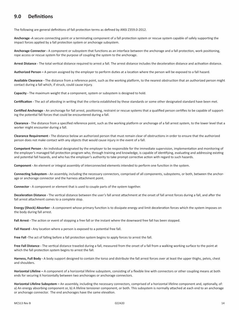
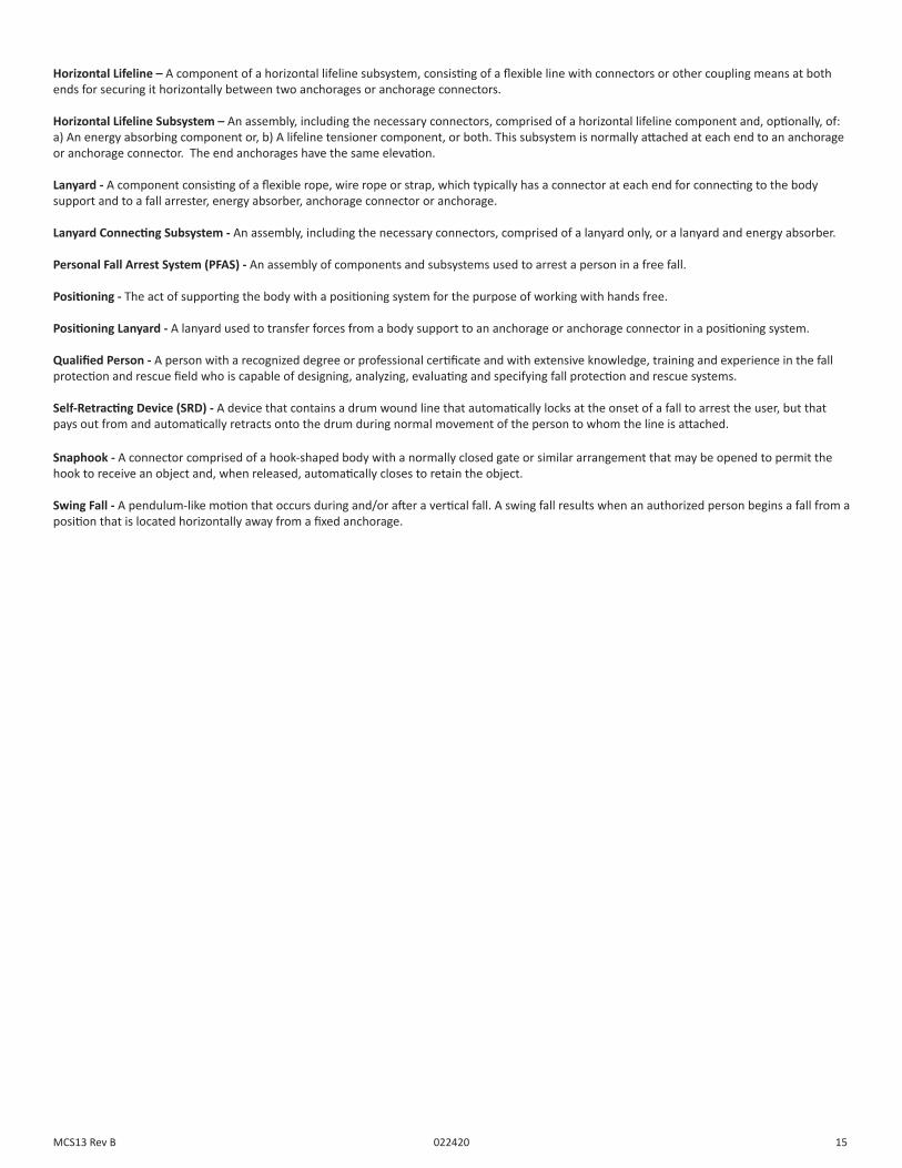
9.0 Definitions
The following are general definitions of fall protection terms as defined by ANSI Z359.0-2012.
Anchorage -A secure connecting point or a terminating component of a fall protection system or rescue system capable of safely supporting the impact forces applied by a fall protection system or anchorage subsystem.
Anchorage Connector - A component or subsystem that functions as an interface between the anchorage and a fall protection, work positioning, rope access or rescue system for the purpose of coupling the system to the anchorage.
Arrest Distance - The total vertical distance required to arrest a fall. The arrest distance includes the deceleration distance and activation distance.
Authorized Person – A person assigned by the employer to perform duties at a location where the person will be exposed to a fall hazard.
Available Clearance - The distance from a reference point, such as the working platform, to the nearest obstruction that an authorized person might contact during a fall which, if struck, could cause injury.
Capacity - The maximum weight that a component, system or subsystem is designed to hold.
Certification - The act of attesting in writing that the criteria established by these standards or some other designated standard have been met.
Certified Anchorage - An anchorage for fall arrest, positioning, restraint or rescue systems that a qualified person certifies to be capable of support-ing the potential fall forces that could be encountered during a fall.
Clearance - The distance from a specified reference point, such as the working platform or anchorage of a fall arrest system, to the lower level that a worker might encounter during a fall.
Clearance Requirement - The distance below an authorized person that must remain clear of obstructions in order to ensure that the authorized person does not make contact with any objects that would cause injury in the event of a fall.
Competent Person - An individual designated by the employer to be responsible for the immediate supervision, implementation and monitoring of the employer’s managed fall protection program who, through training and knowledge, is capable of identifying, evaluating and addressing existing and potential fall hazards, and who has the employer’s authority to take prompt corrective action with regard to such hazards.
Component - An element or integral assembly of interconnected elements intended to perform one function in the system.
Connecting Subsystem - An assembly, including the necessary connectors, comprised of all components, subsystems, or both, between the anchor-age or anchorage connector and the harness attachment point.
Connector - A component or element that is used to couple parts of the system together.
Deceleration Distance - The vertical distance between the user’s fall arrest attachment at the onset of fall arrest forces during a fall, and after the fall arrest attachment comes to a complete stop.
Energy (Shock) Absorber - A component whose primary function is to dissipate energy and limit deceleration forces which the system imposes on the body during fall arrest.
Fall Arrest - The action or event of stopping a free fall or the instant where the downward free fall has been stopped.
Fall Hazard - Any location where a person is exposed to a potential free fall.
Free Fall -The act of falling before a fall protection system begins to apply forces to arrest the fall.
Free Fall Distance - The vertical distance traveled during a fall, measured from the onset of a fall from a walking working surface to the point at which the fall protection system begins to arrest the fall.
Harness, Full Body - A body support designed to contain the torso and distribute the fall arrest forces over at least the upper thighs, pelvis, chest and shoulders.
Horizontal Lifeline – A component of a horizontal lifeline subsystem, consisting of a flexible line with connectors or other coupling means at both ends for securing it horizontally between two anchorages or anchorage connectors.
Horizontal Lifeline Subsystem – An assembly, including the necessary connectors, comprised of a horizontal lifeline component and, optionally, of: a) An energy absorbing component or, b) A lifeline tensioner component, or both. This subsystem is normally attached at each end to an anchorage or anchorage connector. The end anchorages have the same elevation.
14MCS13 Rev B 022420
Horizontal Lifeline – A component of a horizontal lifeline subsystem, consisting of a flexible line with connectors or other coupling means at both ends for securing it horizontally between two anchorages or anchorage connectors.
Horizontal Lifeline Subsystem – An assembly, including the necessary connectors, comprised of a horizontal lifeline component and, optionally, of: a) An energy absorbing component or, b) A lifeline tensioner component, or both. This subsystem is normally attached at each end to an anchorage or anchorage connector. The end anchorages have the same elevation.
Lanyard - A component consisting of a flexible rope, wire rope or strap, which typically has a connector at each end for connecting to the body support and to a fall arrester, energy absorber, anchorage connector or anchorage.
Lanyard Connecting Subsystem - An assembly, including the necessary connectors, comprised of a lanyard only, or a lanyard and energy absorber.
Personal Fall Arrest System (PFAS) - An assembly of components and subsystems used to arrest a person in a free fall.
Positioning - The act of supporting the body with a positioning system for the purpose of working with hands free.
Positioning Lanyard - A lanyard used to transfer forces from a body support to an anchorage or anchorage connector in a positioning system.
Qualified Person - A person with a recognized degree or professional certificate and with extensive knowledge, training and experience in the fall protection and rescue field who is capable of designing, analyzing, evaluating and specifying fall protection and rescue systems.
Self-Retracting Device (SRD) - A device that contains a drum wound line that automatically locks at the onset of a fall to arrest the user, but that pays out from and automatically retracts onto the drum during normal movement of the person to whom the line is attached.
Snaphook - A connector comprised of a hook-shaped body with a normally closed gate or similar arrangement that may be opened to permit the hook to receive an object and, when released, automatically closes to retain the object.
Swing Fall - A pendulum-like motion that occurs during and/or after a vertical fall. A swing fall results when an authorized person begins a fall from a position that is located horizontally away from a fixed anchorage.
15MCS13 Rev B 022420
APPENDIX A
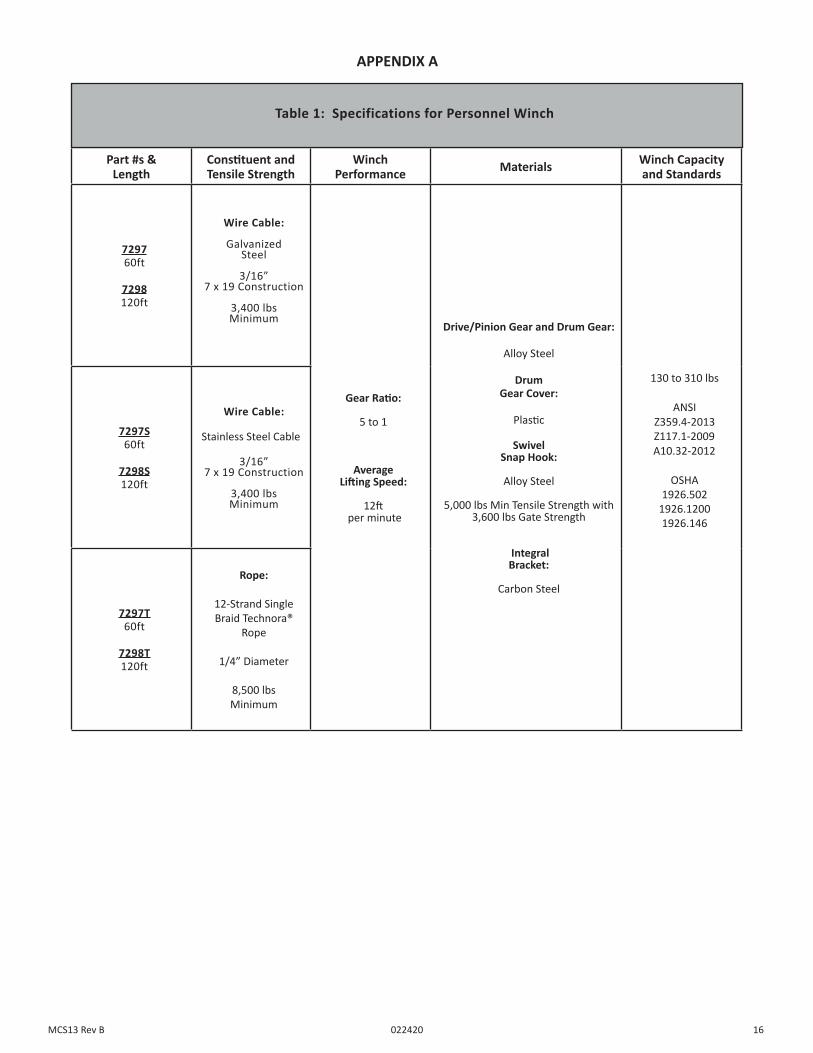
Part #s &Length
Constituent and Tensile Strength
WinchPerformance Materials Winch Capacity
and Standards
729760ft
7298120ft
Wire Cable:
Galvanized Steel
3/16” 7 x 19 Construction
3,400 lbs Minimum
Gear Ratio:
5 to 1
Average Lifting Speed:
12ft per minute
Drive/Pinion Gear and Drum Gear:
Alloy Steel
Drum Gear Cover:
Plastic
Swivel Snap Hook:
Alloy Steel
5,000 lbs Min Tensile Strength with 3,600 lbs Gate Strength
Integral Bracket:
Carbon Steel
130 to 310 lbs
ANSI Z359.4-2013
Z117.1-2009 A10.32-2012
OSHA1926.502
1926.12001926.146
7297S60ft
7298S120ft
Wire Cable:
Stainless Steel Cable
3/16” 7 x 19 Construction
3,400 lbs Minimum
7297T60ft
7298T120ft
Rope:
12-Strand Single Braid Technora®
Rope
1/4” Diameter
8,500 lbs Minimum
Table 1: Specifications for Personnel Winch
16MCS13 Rev B 022420
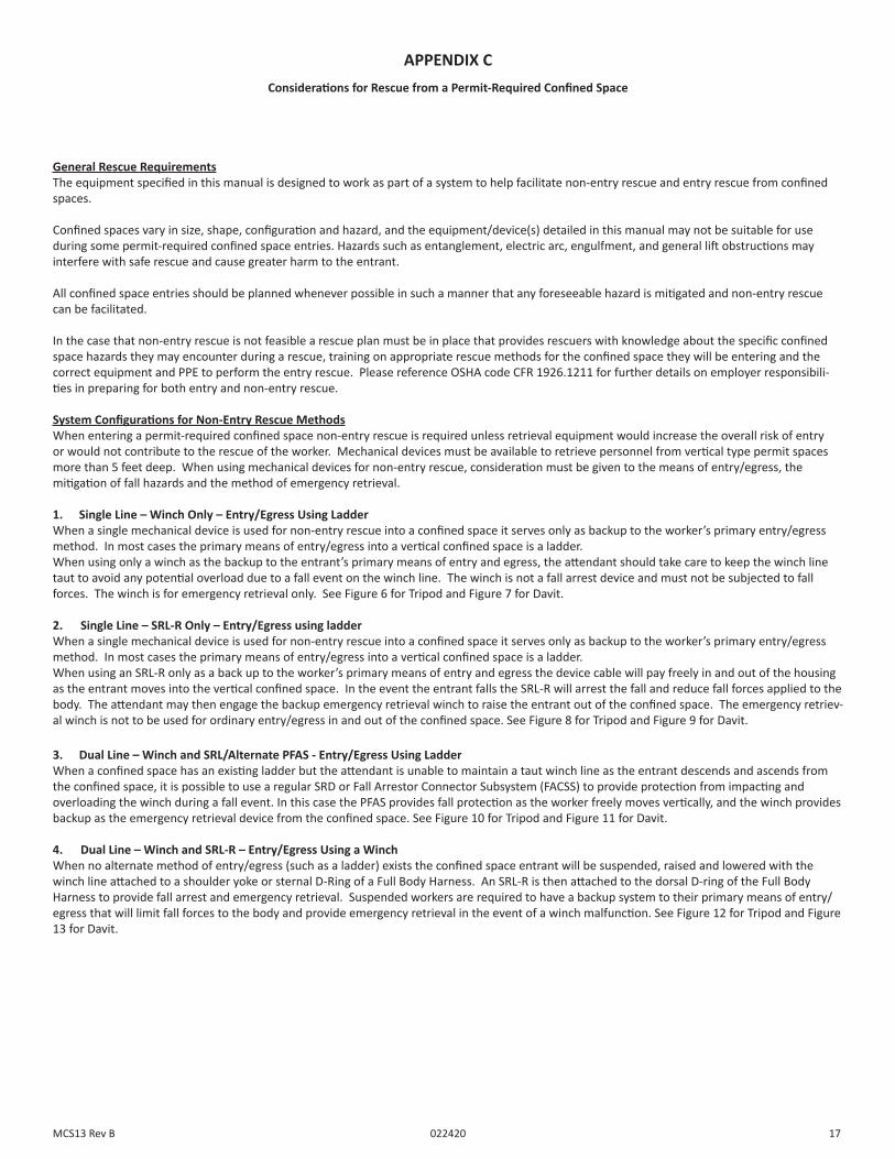
APPENDIX CConsiderations for Rescue from a Permit-Required Confined Space
General Rescue RequirementsThe equipment specified in this manual is designed to work as part of a system to help facilitate non-entry rescue and entry rescue from confined spaces.
Confined spaces vary in size, shape, configuration and hazard, and the equipment/device(s) detailed in this manual may not be suitable for use during some permit-required confined space entries. Hazards such as entanglement, electric arc, engulfment, and general lift obstructions may interfere with safe rescue and cause greater harm to the entrant.
All confined space entries should be planned whenever possible in such a manner that any foreseeable hazard is mitigated and non-entry rescue can be facilitated.
In the case that non-entry rescue is not feasible a rescue plan must be in place that provides rescuers with knowledge about the specific confined space hazards they may encounter during a rescue, training on appropriate rescue methods for the confined space they will be entering and the correct equipment and PPE to perform the entry rescue. Please reference OSHA code CFR 1926.1211 for further details on employer responsibili-ties in preparing for both entry and non-entry rescue.
System Configurations for Non-Entry Rescue MethodsWhen entering a permit-required confined space non-entry rescue is required unless retrieval equipment would increase the overall risk of entry or would not contribute to the rescue of the worker. Mechanical devices must be available to retrieve personnel from vertical type permit spaces more than 5 feet deep. When using mechanical devices for non-entry rescue, consideration must be given to the means of entry/egress, the mitigation of fall hazards and the method of emergency retrieval.
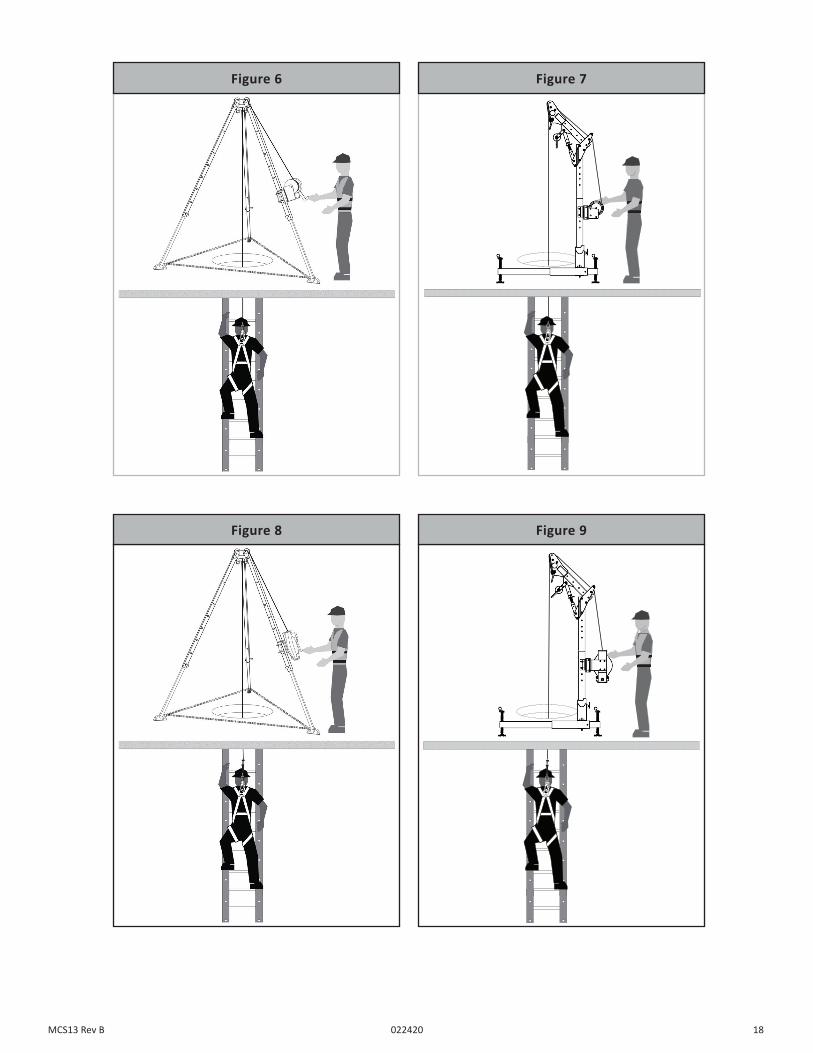
1. Single Line – Winch Only – Entry/Egress Using LadderWhen a single mechanical device is used for non-entry rescue into a confined space it serves only as backup to the worker’s primary entry/egress method. In most cases the primary means of entry/egress into a vertical confined space is a ladder. When using only a winch as the backup to the entrant’s primary means of entry and egress, the attendant should take care to keep the winch line taut to avoid any potential overload due to a fall event on the winch line. The winch is not a fall arrest device and must not be subjected to fall forces. The winch is for emergency retrieval only. See Figure 6 for Tripod and Figure 7 for Davit.
17MCS13 Rev B 022420
2. Single Line – SRL-R Only – Entry/Egress using ladderWhen a single mechanical device is used for non-entry rescue into a confined space it serves only as backup to the worker’s primary entry/egress method. In most cases the primary means of entry/egress into a vertical confined space is a ladder. When using an SRL-R only as a back up to the worker’s primary means of entry and egress the device cable will pay freely in and out of the housing as the entrant moves into the vertical confined space. In the event the entrant falls the SRL-R will arrest the fall and reduce fall forces applied to the body. The attendant may then engage the backup emergency retrieval winch to raise the entrant out of the confined space. The emergency retriev-al winch is not to be used for ordinary entry/egress in and out of the confined space. See Figure 8 for Tripod and Figure 9 for Davit.
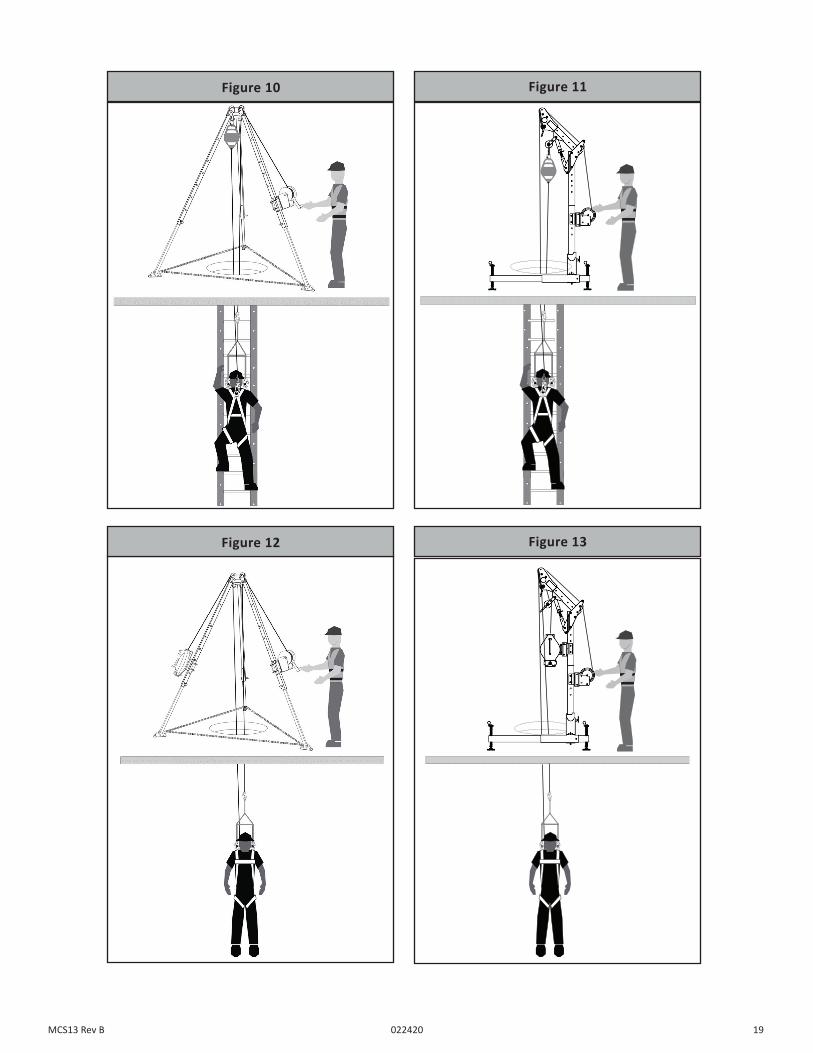
3. Dual Line – Winch and SRL/Alternate PFAS - Entry/Egress Using LadderWhen a confined space has an existing ladder but the attendant is unable to maintain a taut winch line as the entrant descends and ascends from the confined space, it is possible to use a regular SRD or Fall Arrestor Connector Subsystem (FACSS) to provide protection from impacting and overloading the winch during a fall event. In this case the PFAS provides fall protection as the worker freely moves vertically, and the winch provides backup as the emergency retrieval device from the confined space. See Figure 10 for Tripod and Figure 11 for Davit.
4. Dual Line – Winch and SRL-R – Entry/Egress Using a WinchWhen no alternate method of entry/egress (such as a ladder) exists the confined space entrant will be suspended, raised and lowered with the winch line attached to a shoulder yoke or sternal D-Ring of a Full Body Harness. An SRL-R is then attached to the dorsal D-ring of the Full Body Harness to provide fall arrest and emergency retrieval. Suspended workers are required to have a backup system to their primary means of entry/egress that will limit fall forces to the body and provide emergency retrieval in the event of a winch malfunction. See Figure 12 for Tripod and Figure 13 for Davit.
DUCSC
1.1
052715 052715
DUCSC
4.1
051415
Figure 6 Figure 7
DUCSC
1.1
052715 052715
DUCSC
4.1
051415
Figure 8 Figure 9
18MCS13 Rev B 022420
19MCS13 Rev B 022420
DUCSC
1.1
052715 052715
DUCSC
4.1
051415
Figure 10 Figure 11
DUCSC
1.1
052715 052715
DUCSC
4.1
051415
Figure 12 Figure 13