Embed Size (px)
Citation preview
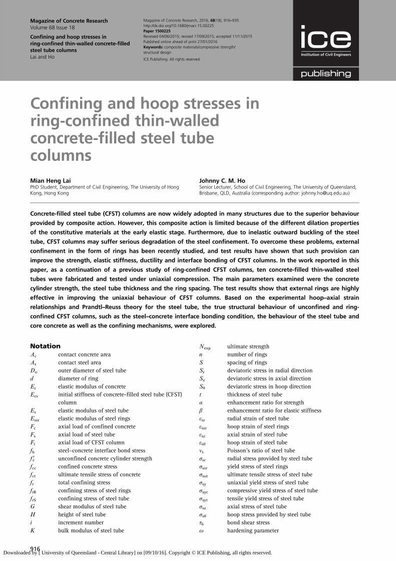
Confining and hoop stresses inring-confined thin-walledconcrete-filled steel tubecolumnsMian Heng LaiPhD Student, Department of Civil Engineering, The University of HongKong, Hong Kong
Johnny C. M. HoSenior Lecturer, School of Civil Engineering, The University of Queensland,Brisbane, QLD, Australia (corresponding author: [email protected])
Concrete-filled steel tube (CFST) columns are now widely adopted in many structures due to the superior behaviour
provided by composite action. However, this composite action is limited because of the different dilation properties
of the constitutive materials at the early elastic stage. Furthermore, due to inelastic outward buckling of the steel
tube, CFST columns may suffer serious degradation of the steel confinement. To overcome these problems, external
confinement in the form of rings has been recently studied, and test results have shown that such provision can
improve the strength, elastic stiffness, ductility and interface bonding of CFST columns. In the work reported in this
paper, as a continuation of a previous study of ring-confined CFST columns, ten concrete-filled thin-walled steel
tubes were fabricated and tested under uniaxial compression. The main parameters examined were the concrete
cylinder strength, the steel tube thickness and the ring spacing. The test results show that external rings are highly
effective in improving the uniaxial behaviour of CFST columns. Based on the experimental hoop–axial strain
relationships and Prandtl–Reuss theory for the steel tube, the true structural behaviour of unconfined and ring-
confined CFST columns, such as the steel–concrete interface bonding condition, the behaviour of the steel tube and
core concrete as well as the confining mechanisms, were explored.
NotationAc contact concrete areaAs contact steel areaDo outer diameter of steel tubed diameter of ringEc elastic modulus of concreteEcs initial stiffness of concrete-filled steel tube (CFST)
columnEs elastic modulus of steel tubeEssr elastic modulus of steel ringsFc axial load of confined concreteFs axial load of steel tubeFt axial load of CFST columnfb steel–concrete interface bond stressf 0c unconfined concrete cylinder strengthfcc confined concrete stressfct ultimate tensile stress of concretefr total confining stressfrR confining stress of steel ringsfrS confining stress of steel tubeG shear modulus of steel tubeH height of steel tubei increment numberK bulk modulus of steel tube
Nexp ultimate strengthn number of ringsS spacing of ringsSr deviatoric stress in radial directionSz deviatoric stress in axial directionSθ deviatoric stress in hoop directiont thickness of steel tubeα enhancement ratio for strengthβ enhancement ratio for elastic stiffnessεsr radial strain of steel tubeεssr hoop strain of steel ringsεsz axial strain of steel tubeεsθ hoop strain of steel tubeνs Poisson’s ratio of steel tubeσsr radial stress provided by steel tubeσssr yield stress of steel ringsσsut ultimate tensile stress of steel tubeσsy uniaxial yield stress of steel tubeσsyc compressive yield stress of steel tubeσsyt tensile yield stress of steel tubeσsz axial stress of steel tubeσsθ hoop stress provided by steel tubeτb bond shear stressω hardening parameter
916
Magazine of Concrete ResearchVolume 68 Issue 18
Confining and hoop stresses inring-confined thin-walled concrete-filledsteel tube columnsLai and Ho
Magazine of Concrete Research, 2016, 68(18), 916–935http://dx.doi.org/10.1680/jmacr.15.00225Paper 1500225Received 04/06/2015; revised 17/09/2015; accepted 11/11/2015Published online ahead of print 27/01/2016Keywords: composite materials/compressive strength/structural design
ICE Publishing: All rights reserved
Downloaded by [ University of Queensland - Central Library] on [09/10/16]. Copyright © ICE Publishing, all rights reserved.
IntroductionConcrete-filled steel tube (CFST) columns, which consist ofhollow steel tube (HST) columns in-filled with concrete, arenow widely used in many structures due to the superior behav-iour provided by the composite action (Uy, 2001; Uy et al.,2011; Zhong, 2006). In CFST columns, due to the supportingeffect provided by the core concrete, inward buckling of thesteel tube can be prevented, resulting in a higher bucklingresistance (Bradford et al., 2002; Uy, 1998). Moreover, the steeltube can act as both longitudinal and transverse reinforcement,which provides both axial resistance and confining stress.This uniform confining stress can improve the strength andductility of core concrete much more effectively than stirrupsin traditional reinforced concrete columns (Zhong, 2006).Furthermore, since the steel tube serves as permanent form-work, this system saves on construction materials and shortensconstruction cycle time (Uy and Das, 1997). However, despitethese advantages, CFST columns also have the following draw-backs. During the initial elastic stage under compression, dueto the different dilation properties of the steel tube and theconcrete (Lai and Ho, 2014b; Lu and Hsu, 2007), the corre-sponding confining stress may become negative (i.e. hoop com-pressive stress). This will reduce the strength, elastic stiffnessand ductility of the CFST column (Ho and Lai, 2013; Lai andHo, 2014a). The confining stress will be activated only whenmicrocracking of the concrete starts to form and the expansionof the concrete exceeds that of the steel tube. On the otherhand, degradation of confining stress, strength and ductilitywill occur in the post-elastic stage due to the inelastic outwardbuckling of the steel tube. These problems are more prominentwhen a thin-walled steel tube with high-strength concrete(HSC) is used, as reported in many research studies (Hu et al.,2011; O’Shea and Bridge, 2000; Tao et al., 2008).
Various approaches have been proposed to overcome thesedeficiencies and fully utilise the composite action of CFSTcolumns (Cai and He, 2006; Dabaon et al., 2009; GaneshPrabhu and Sundarraja, 2013; Ho and Lai, 2013; Ho et al.,2014; Huang et al., 2002; Lai and Ho, 2014a, 2014b; Petruset al., 2010). A brief review of these approaches was conductedby the authors (Lai and Ho, 2015a) and it was concluded thatalthough installing internal stiffeners can improve the steel–concrete interface bonding and delay the local buckling ofCFST columns, the enhancement effects on the strength, stiff-ness and ductility are not as effective as external confiningschemes. This is because external confining schemes canprovide additional confining stress to improve the strength andductility of the core concrete and CFST columns.Furthermore, internal stiffeners, if the spacing is too small, areimpractical when considering the concrete placing quality inthe construction (i.e. honeycombing or segregation can easilyoccur). Research on circular CFST columns with internal stif-feners is still limited because welding on the plates is mucheasier and more controllable than welding on the shell.Specimens confined using fibre reinforced polymer (FRP) can
fail suddenly near the mid-height region without amplewarning due to the linear-elastic–brittle stress–strain behaviourof FRP wraps. Other disadvantages of this confining schemeinclude the relatively high cost, poor fire resistance and lowelastic modulus to strength ratio of the FRP wraps.
In current practical construction, it is very common to seeCFST columns of very large diameter (up to 2 m), but it isalso not uncommon to encounter smaller diameter CFSTcolumns (< 1 m) in the higher storeys of tall buildings and inlow- to medium-rise residential buildings. Smaller sized CFSTcolumns
& provide increased buckling stability compared withreinforced concrete columns because the concrete restrainsthe column to buckle inwards
& result in lower construction and maintenance costs andreduced construction and demolition wastes, thus offeringa lower carbon dioxide infrastructure that helps to create amore sustainable living environment, which is a goal of allstructural/material engineers
& are more favourable to architects and developers and canbe utilised for different purposes.
In CFST columns, the welding of external rings – which canprovide adequate confining stress to improve the strength, duct-ility and stability of the column – is easier than the installationof internal stiffeners. A novel form of external steel ring con-finement proposed by the authors (Ho et al., 2014; Lai andHo, 2014a, 2014b) is thus one of the best methods to improvethe uniaxial behaviour of CFST columns. Due to theadditional confining stress provided by rings in ring-confinedCFST columns, the steel–concrete interface bonding isimproved and the inelastic outward buckling of the steel tubeis prevented or at least delayed, resulting in higher strength,elastic stiffness and ductility of the CFST column. Results ofprevious work showed that the maximum load-carryingcapacity and initial stiffness of confined specimens wererespectively 49% and 26% larger than unconfined counterparts(Lai and Ho, 2014b).
The authors’ previous studies (Ho et al., 2014; Lai and Ho,2014a, 2014b) have demonstrated the beneficial effects ofadopting steel rings as external confinement, but better under-standing of the true structural behaviour of unconfined andring-confined CFST columns is still required. Precise modelsare needed to explore the actual behaviour of CFST columns,such as the steel–concrete interface bonding, the stress state ofthe steel tube, the behaviour of core concrete and so on.Moreover, the steel tubes used in the authors’ previous studieswere relatively thick, with a diameter/thickness ratio of lessthan 35.
As a continuation of the authors’ studies into ring-confinedCFST columns, ten concrete-filled thin-walled steel tubes
917
Magazine of Concrete ResearchVolume 68 Issue 18
Confining and hoop stresses inring-confined thin-walled concrete-filledsteel tube columnsLai and Ho
Downloaded by [ University of Queensland - Central Library] on [09/10/16]. Copyright © ICE Publishing, all rights reserved.
(eight specimens with a diameter/thickness ratio of about 40and two specimens with a diameter/thickness ratio of over 100)were fabricated and tested under uniaxial load. The purpose ofthese experimental tests was
& to study the behaviour of thin-walled specimens and theinfluence of steel tube thickness
& to examine the beneficial effect of external confinement onthin-walled specimens
& to explore the true structural behaviour of constitutivecomponents of CFST columns by developing a precisemodel.
Experimental programme
SpecimensA total of ten concrete-filled thin-walled steel tubes were fabri-cated and tested under uniaxial load. The material propertiesof the specimens are listed in Table 1. Specimens were dividedinto two groups depending on the concrete cylinder strength(f 0c) – five CFST columns with f 0c = 30 MPa and five CFSTcolumns with f 0c = 80 MPa. Each group consisted of three ring-confined CFST columns and two unconfined CFST columns.In order to study the influence of steel tube thickness, one ofthe unconfined columns had a tube thickness of 1 mm and theother 3 mm. All the three ring-confined CFST had a tubethickness of 3 mm. The nominal outer diameter of all fivespecimens was 114·3 mm. The measured outer diameter (Do)and thickness (t) of the steel tube are summarised in Table 1.To reduce ‘end effects’ and minimise the slenderness ratio(Han et al., 2005; Lai and Ho, 2015a; Yu et al., 2007), thespecimens were fabricated to be exactly 350 mm in height (H ),which was about three times the outer diameter. Steel ringswere installed at different spacings (S=60, 90 and 120 mm),which was approximately 20t, 30t and 40t (t=3 mm) for thethree confined CFST columns in each group. The nominaldiameter (d ) of the rings was 6 mm and the nominal andactual yield strengths of the rings were 250 MPa and
304 MPa, respectively. The rings were intermittently welded tothe external surface of the steel tube at four welding spots (sep-arated from each other by 90°) at each level. To fully developthe yield strength of rings, a minimum overlapping of 10d(60 mm) was provided.
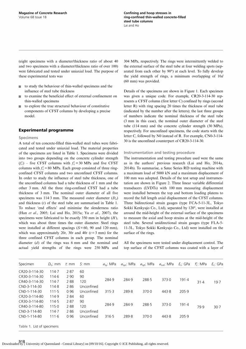
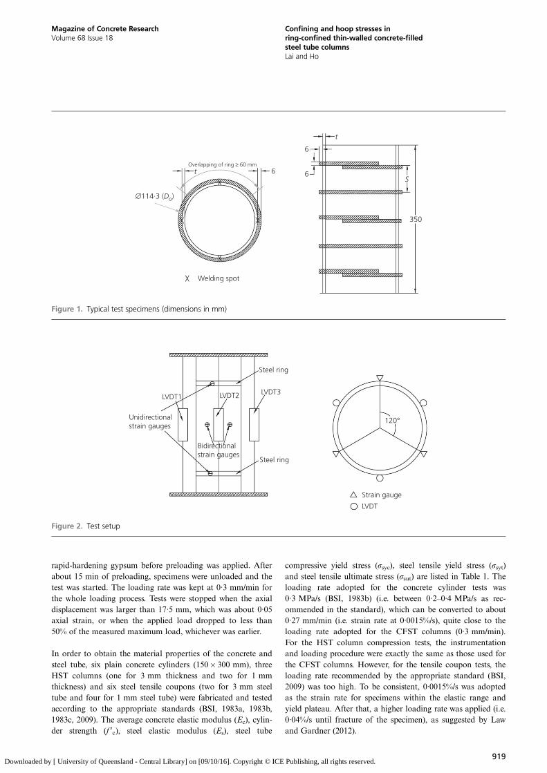
Details of the specimens are shown in Figure 1. Each specimenwas given a unique code. For example, CR20-3-114-30 rep-resents a CFST column (first letter C) confined by rings (secondletter R) with ring spacing 20 times the thickness of steel tube(indicated by the number after the letters); the last three groupsof numbers indicate the nominal thickness of the steel tube(3 mm in this case), the nominal outer diameter of the steeltube (114 mm) and the concrete cylinder strength (30 MPa),respectively. For unconfined specimens, the code starts with theletter C, followed by N0 instead of R. For example, CN0-3-114-30 is the unconfined counterpart of CR20-3-114-30.
Instrumentation and testing procedureThe instrumentation and testing procedure used were the sameas in the authors’ previous research (Lai and Ho, 2014a,2014b). To summarise, a Satec Series RD testing machine witha maximum load of 5000 kN and a maximum displacement of100 mm was adopted. Details of the test setup and instrumen-tation are shown in Figure 2. Three linear variable differentialtransducers (LVDTs) with 100 mm measuring displacementwere installed between the top and bottom loading platens torecord the full length axial displacement of the CFST columns.Three bidirectional strain gauges (type FCA-5-11-3L, TokyoSokki Kenkyujo Co., Ltd), separated by 120°, were installed ataround the mid-height of the external surface of the specimensto measure the axial and hoop strains at the mid-height of thesteel tube. Several unidirectional strain gauges (type FLA-5-11-3L, Tokyo Sokki Kenkyujo Co., Ltd) were installed on thesurface of the rings.
All the specimens were tested under displacement control. Thetop surface of the CFST columns was coated with a layer of
Specimen Do: mm t: mm S: mm σsy: MPa σsyc: MPa σsyt: MPa σsut: MPa Es: GPa f 0c: MPa Ec: GPa
CR20-3-114-30 114·7 2·87 60
284·9 284·9 288·5 373·0 191·431·4 19·7
CR30-3-114-30 114·6 2·90 90CR40-3-114-30 114·7 2·88 120CN0-3-114-30 114·8 2·86 UnconfinedCN0-1-114-30 111·5 0·96 Unconfined 315·3 289·8 370·0 443·8 205·9CR20-3-114-80 114·9 2·84 60
284·9 284·9 288·5 373·0 191·479·9 30·7
CR30-3-114-80 114·5 2·87 90CR40-3-114-80 115·0 2·88 120CN0-3-114-80 114·7 2·86 UnconfinedCN0-1-114-80 111·6 0·96 Unconfined 316·5 289·8 370·0 443·8 205·9
Table 1. List of specimens
918
Magazine of Concrete ResearchVolume 68 Issue 18
Confining and hoop stresses inring-confined thin-walled concrete-filledsteel tube columnsLai and Ho
Downloaded by [ University of Queensland - Central Library] on [09/10/16]. Copyright © ICE Publishing, all rights reserved.
rapid-hardening gypsum before preloading was applied. Afterabout 15 min of preloading, specimens were unloaded and thetest was started. The loading rate was kept at 0·3 mm/min forthe whole loading process. Tests were stopped when the axialdisplacement was larger than 17·5 mm, which was about 0·05axial strain, or when the applied load dropped to less than50% of the measured maximum load, whichever was earlier.
In order to obtain the material properties of the concrete andsteel tube, six plain concrete cylinders (150� 300 mm), threeHST columns (one for 3 mm thickness and two for 1 mmthickness) and six steel tensile coupons (two for 3 mm steeltube and four for 1 mm steel tube) were fabricated and testedaccording to the appropriate standards (BSI, 1983a, 1983b,1983c, 2009). The average concrete elastic modulus (Ec), cylin-der strength (f 0c), steel elastic modulus (Es), steel tube
compressive yield stress (σsyc), steel tensile yield stress (σsyt)and steel tensile ultimate stress (σsut) are listed in Table 1. Theloading rate adopted for the concrete cylinder tests was0·3 MPa/s (BSI, 1983b) (i.e. between 0·2–0·4 MPa/s as rec-ommended in the standard), which can be converted to about0·27 mm/min (i.e. strain rate at 0·0015%/s), quite close to theloading rate adopted for the CFST columns (0·3 mm/min).For the HST column compression tests, the instrumentationand loading procedure were exactly the same as those used forthe CFST columns. However, for the tensile coupon tests, theloading rate recommended by the appropriate standard (BSI,2009) was too high. To be consistent, 0·0015%/s was adoptedas the strain rate for specimens within the elastic range andyield plateau. After that, a higher loading rate was applied (i.e.0·04%/s until fracture of the specimen), as suggested by Lawand Gardner (2012).
t
t
6
66
∅114·3 (Do)
Overlapping of ring ≥ 60 mm
Welding spot
S
350
Figure 1. Typical test specimens (dimensions in mm)
Steel ring
Steel ring
LVDT3LVDT2LVDT1
Unidirectionalstrain gauges
Bidirectionalstrain gauges
Strain gauge
LVDT
120°
Figure 2. Test setup
919
Magazine of Concrete ResearchVolume 68 Issue 18
Confining and hoop stresses inring-confined thin-walled concrete-filledsteel tube columnsLai and Ho
Downloaded by [ University of Queensland - Central Library] on [09/10/16]. Copyright © ICE Publishing, all rights reserved.
It should be noted that this experimental programme was con-ducted based on steel tube with a relatively small diameter(139 mm) due to the limitation of the testing machine(maximum load-carrying capacity of 5000 kN). Therefore,further full-scale testing may be required in order to verify theconclusions obtained in this work for mega-sized CFSTcolumns.
Experimental results and discussion
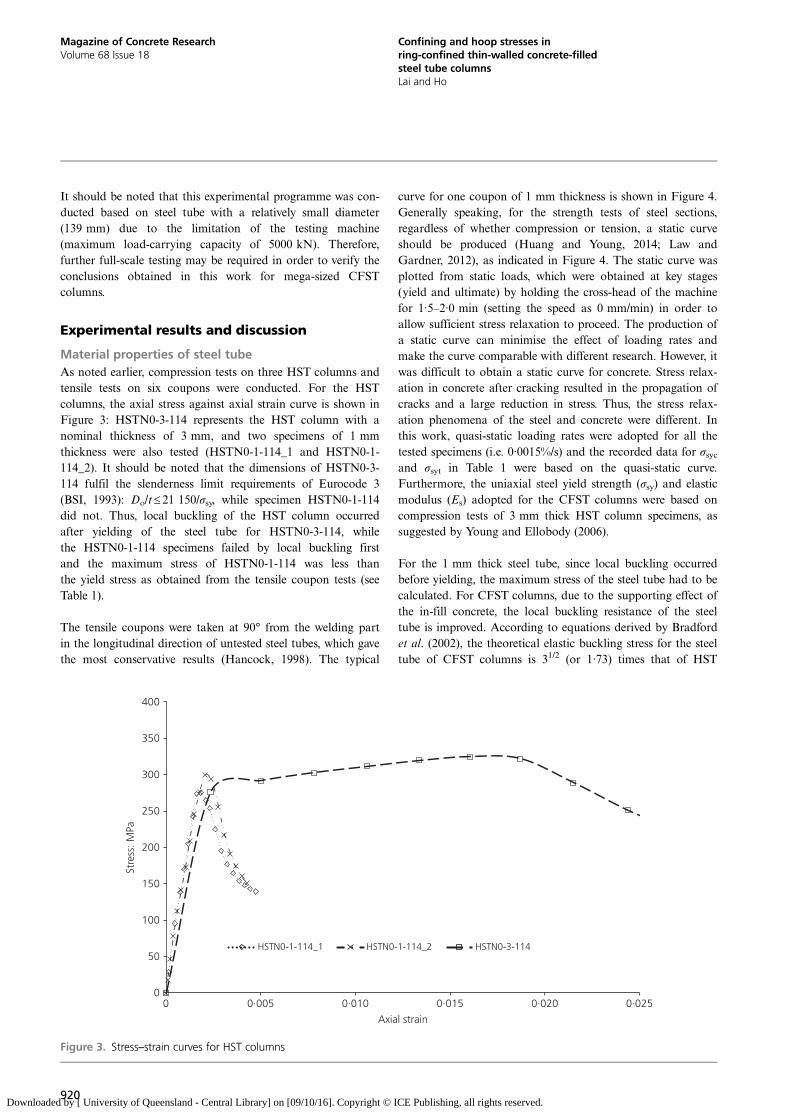
Material properties of steel tubeAs noted earlier, compression tests on three HST columns andtensile tests on six coupons were conducted. For the HSTcolumns, the axial stress against axial strain curve is shown inFigure 3: HSTN0-3-114 represents the HST column with anominal thickness of 3 mm, and two specimens of 1 mmthickness were also tested (HSTN0-1-114_1 and HSTN0-1-114_2). It should be noted that the dimensions of HSTN0-3-114 fulfil the slenderness limit requirements of Eurocode 3(BSI, 1993): Do/t ≤ 21 150/σsy, while specimen HSTN0-1-114did not. Thus, local buckling of the HST column occurredafter yielding of the steel tube for HSTN0-3-114, whilethe HSTN0-1-114 specimens failed by local buckling firstand the maximum stress of HSTN0-1-114 was less thanthe yield stress as obtained from the tensile coupon tests (seeTable 1).
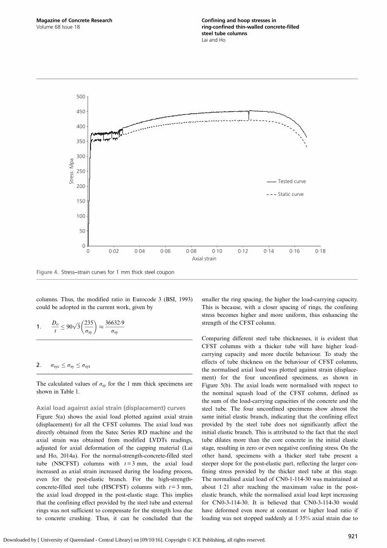
The tensile coupons were taken at 90° from the welding partin the longitudinal direction of untested steel tubes, which gavethe most conservative results (Hancock, 1998). The typical
curve for one coupon of 1 mm thickness is shown in Figure 4.Generally speaking, for the strength tests of steel sections,regardless of whether compression or tension, a static curveshould be produced (Huang and Young, 2014; Law andGardner, 2012), as indicated in Figure 4. The static curve wasplotted from static loads, which were obtained at key stages(yield and ultimate) by holding the cross-head of the machinefor 1·5–2·0 min (setting the speed as 0 mm/min) in order toallow sufficient stress relaxation to proceed. The production ofa static curve can minimise the effect of loading rates andmake the curve comparable with different research. However, itwas difficult to obtain a static curve for concrete. Stress relax-ation in concrete after cracking resulted in the propagation ofcracks and a large reduction in stress. Thus, the stress relax-ation phenomena of the steel and concrete were different. Inthis work, quasi-static loading rates were adopted for all thetested specimens (i.e. 0·0015%/s) and the recorded data for σsycand σsyt in Table 1 were based on the quasi-static curve.Furthermore, the uniaxial steel yield strength (σsy) and elasticmodulus (Es) adopted for the CFST columns were based oncompression tests of 3 mm thick HST column specimens, assuggested by Young and Ellobody (2006).
For the 1 mm thick steel tube, since local buckling occurredbefore yielding, the maximum stress of the steel tube had to becalculated. For CFST columns, due to the supporting effect ofthe in-fill concrete, the local buckling resistance of the steeltube is improved. According to equations derived by Bradfordet al. (2002), the theoretical elastic buckling stress for the steeltube of CFST columns is 31/2 (or 1·73) times that of HST
0
50
100
150
200
250
300
350
400
0 0·005 0·010 0·015 0·020 0·025
Stre
ss: M
Pa
Axial strain
HSTN0-1-114_1 HSTN0-1-114_2 HSTN0-3-114
Figure 3. Stress–strain curves for HST columns
920
Magazine of Concrete ResearchVolume 68 Issue 18
Confining and hoop stresses inring-confined thin-walled concrete-filledsteel tube columnsLai and Ho
Downloaded by [ University of Queensland - Central Library] on [09/10/16]. Copyright © ICE Publishing, all rights reserved.
columns. Thus, the modified ratio in Eurocode 3 (BSI, 1993)could be adopted in the current work, given by
1:Do
t� 90
ffiffiffi3
p 235σsy
� �� 36632�9
σsy
2: σsyc � σsy � σsyt
The calculated values of σsy for the 1 mm thick specimens areshown in Table 1.
Axial load against axial strain (displacement) curvesFigure 5(a) shows the axial load plotted against axial strain(displacement) for all the CFST columns. The axial load wasdirectly obtained from the Satec Series RD machine and theaxial strain was obtained from modified LVDTs readings,adjusted for axial deformation of the capping material (Laiand Ho, 2014a). For the normal-strength-concrete-filled steeltube (NSCFST) columns with t=3 mm, the axial loadincreased as axial strain increased during the loading process,even for the post-elastic branch. For the high-strength-concrete-filled steel tube (HSCFST) columns with t=3 mm,the axial load dropped in the post-elastic stage. This impliesthat the confining effect provided by the steel tube and externalrings was not sufficient to compensate for the strength loss dueto concrete crushing. Thus, it can be concluded that the
smaller the ring spacing, the higher the load-carrying capacity.This is because, with a closer spacing of rings, the confiningstress becomes higher and more uniform, thus enhancing thestrength of the CFST column.
Comparing different steel tube thicknesses, it is evident thatCFST columns with a thicker tube will have higher load-carrying capacity and more ductile behaviour. To study theeffects of tube thickness on the behaviour of CFST columns,the normalised axial load was plotted against strain (displace-ment) for the four unconfined specimens, as shown inFigure 5(b). The axial loads were normalised with respect tothe nominal squash load of the CFST column, defined asthe sum of the load-carrying capacities of the concrete and thesteel tube. The four unconfined specimens show almost thesame initial elastic branch, indicating that the confining effectprovided by the steel tube does not significantly affect theinitial elastic branch. This is attributed to the fact that the steeltube dilates more than the core concrete in the initial elasticstage, resulting in zero or even negative confining stress. On theother hand, specimens with a thicker steel tube present asteeper slope for the post-elastic part, reflecting the larger con-fining stress provided by the thicker steel tube at this stage.The normalised axial load of CN0-1-114-30 was maintained atabout 1·21 after reaching the maximum value in the post-elastic branch, while the normalised axial load kept increasingfor CN0-3-114-30. It is believed that CN0-3-114-30 wouldhave deformed even more at constant or higher load ratio ifloading was not stopped suddenly at 1·35% axial strain due to
0
50
100
150
200
250
300
350
400
450
500
0 0·02 0·04 0·06 0·08 0·10 0·12 0·14 0·16 0·18
Stre
ss: M
pa
Axial strain
Tested curve
Static curve
Figure 4. Stress–strain curves for 1 mm thick steel coupon
921
Magazine of Concrete ResearchVolume 68 Issue 18
Confining and hoop stresses inring-confined thin-walled concrete-filledsteel tube columnsLai and Ho
Downloaded by [ University of Queensland - Central Library] on [09/10/16]. Copyright © ICE Publishing, all rights reserved.
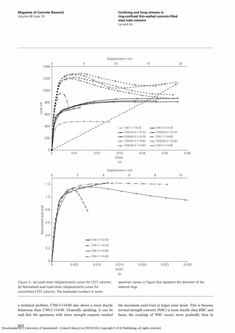
a technical problem. CN0-3-114-80 also shows a more ductilebehaviour than CN0-1-114-80. Generally speaking, it can besaid that the specimens with lower strength concrete reached
the maximum axial load at larger axial strain. This is becausenormal-strength concrete (NSC) is more ductile than HSC andhence the cracking of NSC occurs more gradually than in
0 5 10 15 20
0
200
400
600
800
1000
1200
1400
0 0·01 0·02 0·03 0·04 0·05 0·06
Displacement: mm
Load
: kN
Strain (a)
CN0-1-114-30 CN0-3-114-30
CR(6)20-3-114-30 CR(6)30-3-114-30
CR(6)40-3-114-30 CN0-1-114-80
CR(6)20-3-114-80 CR(6)30-3-114-80
CR(6)40-3-114-80 CN0-3-114-80
0 2 4 6 8 10
0
0·2
0·4
0·6
0·8
1·0
1·2
0 0·005 0·010 0·015 0·020 0·025 0·030
Displacement: mm
Nor
mal
ised
axi
al lo
ad
Strain
(b)
CN0-3-114-30
CN0-1-114-30
CN0-3-114-80
CN0-1-114-80
Figure 5. (a) Load–strain (displacement) curves for CFST columns.
(b) Normalised axial load–strain (displacement) curves for
unconfined CFST columns. The bracketed numbers in some
specimen names in Figure 5(a) represent the diameter of the
external rings
922
Magazine of Concrete ResearchVolume 68 Issue 18
Confining and hoop stresses inring-confined thin-walled concrete-filledsteel tube columnsLai and Ho
Downloaded by [ University of Queensland - Central Library] on [09/10/16]. Copyright © ICE Publishing, all rights reserved.
HSC during the post-elastic stage, resulting in smaller concretedilation and confining stress.
To quantify the effectiveness of external rings, the ultimatestrength (Nexp) and initial stiffness (Ecs) are listed in Table 2.Nexp is defined as the strength at 1·5% strain or the first peakstrength, whichever is larger. This definition of Nexp was usedhere because
& for most of the CFST columns showing strain degradationat the post-peak stage, the strain corresponding to the peakstrength was generally smaller than 1·5% (Lai and Ho,2015b)
& the steel tube was in the yield stage at 1·5% strain, whenthe strain hardening behaviour of the steel tube can beignored (Ho et al., 2005)
& most of the strain gauges did not fail before 1·5% strain,which is very important for the analysis; forspecimen CN0-3-114-30, since the tested stopped at1·35% strain, the load gained at the end of the test wastermed Nexp.
On the other hand, Ecs was taken as the slope of the initialpart of the axial load–strain curves, and further divided by thecross-sectional area of the CFST column (contact steel area(As) plus contact concrete area (Ac)). Two parameters wereadopted to evaluate the effects of the rings; these were theenhancement ratios for strength (α) and elastic stiffness (β),given by
3: α ¼ Nexp�c
Nexp�u
4: β ¼ Ecs�c
Ecs�u
where Nexp-c and Nexp-u refer to the ultimate loads for confinedand unconfined specimens, respectively and Ecs-c and Ecs-u
refer to the elastic stiffnesses for confined and unconfinedspecimens respectively.
It can be concluded from Table 2 that both the strength andelastic stiffness were improved with the addition of rings. Themaximum improvement in ultimate load by adding rings was10% for CR20-3-114-30. More importantly, the more ringsadded, the larger were the enhancement ratios. It can thereforebe concluded that rings are highly effective in improving theuniaxial behaviour of CFST columns.
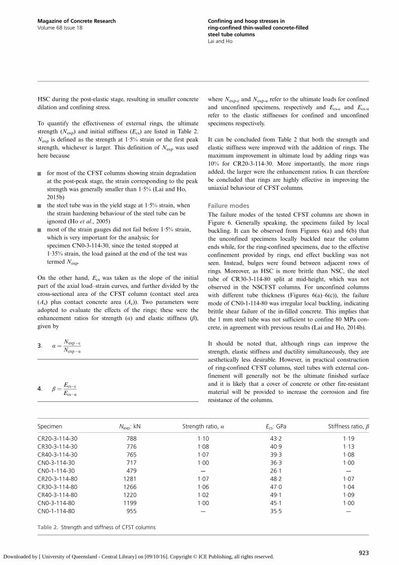
Failure modesThe failure modes of the tested CFST columns are shown inFigure 6. Generally speaking, the specimens failed by localbuckling. It can be observed from Figures 6(a) and 6(b) thatthe unconfined specimens locally buckled near the columnends while, for the ring-confined specimens, due to the effectiveconfinement provided by rings, end effect buckling was notseen. Instead, bulges were found between adjacent rows ofrings. Moreover, as HSC is more brittle than NSC, the steeltube of CR30-3-114-80 split at mid-height, which was notobserved in the NSCFST columns. For unconfined columnswith different tube thickness (Figures 6(a)–6(c)), the failuremode of CN0-1-114-80 was irregular local buckling, indicatingbrittle shear failure of the in-filled concrete. This implies thatthe 1 mm steel tube was not sufficient to confine 80 MPa con-crete, in agreement with previous results (Lai and Ho, 2014b).
It should be noted that, although rings can improve thestrength, elastic stiffness and ductility simultaneously, they areaesthetically less desirable. However, in practical constructionof ring-confined CFST columns, steel tubes with external con-finement will generally not be the ultimate finished surfaceand it is likely that a cover of concrete or other fire-resistantmaterial will be provided to increase the corrosion and fireresistance of the columns.
Specimen Nexp: kN Strength ratio, α Ecs: GPa Stiffness ratio, β
CR20-3-114-30 788 1·10 43·2 1·19CR30-3-114-30 776 1·08 40·9 1·13CR40-3-114-30 765 1·07 39·3 1·08CN0-3-114-30 717 1·00 36·3 1·00CN0-1-114-30 479 — 26·1 —
CR20-3-114-80 1281 1·07 48·2 1·07CR30-3-114-80 1266 1·06 47·0 1·04CR40-3-114-80 1220 1·02 49·1 1·09CN0-3-114-80 1199 1·00 45·1 1·00CN0-1-114-80 955 — 35·5 —
Table 2. Strength and stiffness of CFST columns
923
Magazine of Concrete ResearchVolume 68 Issue 18
Confining and hoop stresses inring-confined thin-walled concrete-filledsteel tube columnsLai and Ho
Downloaded by [ University of Queensland - Central Library] on [09/10/16]. Copyright © ICE Publishing, all rights reserved.
End effect Local buckling between rings
End effect
End effect
Rupture of steel tube
Irregularlocalbuckling
(a)
(b)
(c)
Local buckling between rings
Figure 6. Failure modes: (a) CRn-3-114-30 specimens and
counterpart specimen without rings; (b) CRn-3-114-80 and
counterpart specimen without rings; (c) CN0-1-114-X (left, NSC;
right, HSC)
924
Magazine of Concrete ResearchVolume 68 Issue 18
Confining and hoop stresses inring-confined thin-walled concrete-filledsteel tube columnsLai and Ho
Downloaded by [ University of Queensland - Central Library] on [09/10/16]. Copyright © ICE Publishing, all rights reserved.
Modelling of thin-walled CFST columnsIn order to better understand the structural behaviour ofunconfined and ring-confined CFST columns fabricated usingthin-walled steel tube, a precise model that considers the steel–concrete interface bonding condition, the stress state of thesteel tube and the behaviour of the core concrete was devel-oped. The model starts with the experimental hoop–axialstrain relationship and this is followed by the Prandtl–Reusstheory for steel tubes. The behaviour of individual componentsof CFST columns is then discussed.
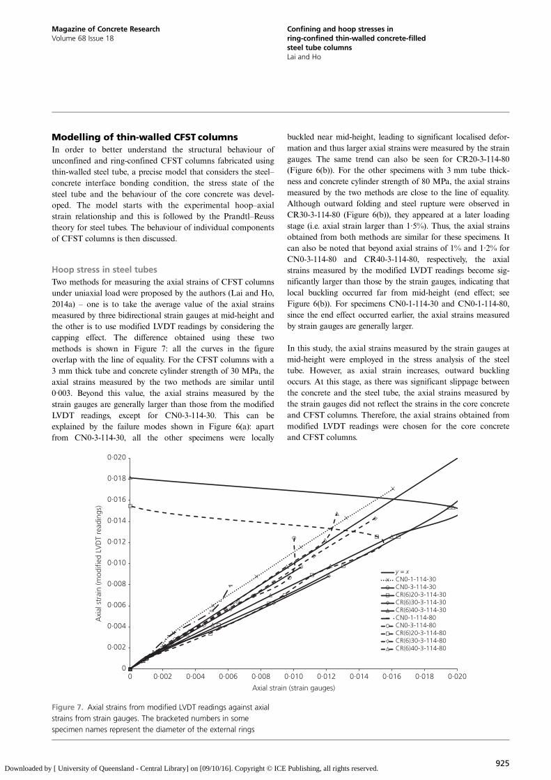
Hoop stress in steel tubesTwo methods for measuring the axial strains of CFST columnsunder uniaxial load were proposed by the authors (Lai and Ho,2014a) – one is to take the average value of the axial strainsmeasured by three bidirectional strain gauges at mid-height andthe other is to use modified LVDT readings by considering thecapping effect. The difference obtained using these twomethods is shown in Figure 7: all the curves in the figureoverlap with the line of equality. For the CFST columns with a3 mm thick tube and concrete cylinder strength of 30 MPa, theaxial strains measured by the two methods are similar until0·003. Beyond this value, the axial strains measured by thestrain gauges are generally larger than those from the modifiedLVDT readings, except for CN0-3-114-30. This can beexplained by the failure modes shown in Figure 6(a): apartfrom CN0-3-114-30, all the other specimens were locally
buckled near mid-height, leading to significant localised defor-mation and thus larger axial strains were measured by the straingauges. The same trend can also be seen for CR20-3-114-80(Figure 6(b)). For the other specimens with 3 mm tube thick-ness and concrete cylinder strength of 80 MPa, the axial strainsmeasured by the two methods are close to the line of equality.Although outward folding and steel rupture were observed inCR30-3-114-80 (Figure 6(b)), they appeared at a later loadingstage (i.e. axial strain larger than 1·5%). Thus, the axial strainsobtained from both methods are similar for these specimens. Itcan also be noted that beyond axial strains of 1% and 1·2% forCN0-3-114-80 and CR40-3-114-80, respectively, the axialstrains measured by the modified LVDT readings become sig-nificantly larger than those by the strain gauges, indicating thatlocal buckling occurred far from mid-height (end effect; seeFigure 6(b)). For specimens CN0-1-114-30 and CN0-1-114-80,since the end effect occurred earlier, the axial strains measuredby strain gauges are generally larger.
In this study, the axial strains measured by the strain gauges atmid-height were employed in the stress analysis of the steeltube. However, as axial strain increases, outward bucklingoccurs. At this stage, as there was significant slippage betweenthe concrete and the steel tube, the axial strains measured bythe strain gauges did not reflect the strains in the core concreteand CFST columns. Therefore, the axial strains obtained frommodified LVDT readings were chosen for the core concreteand CFST columns.
0
0·002
0·004
0·006
0·008
0·010
0·012
0·014
0·016
0·018
0·020
0 0·002 0·004 0·006 0·008 0·010 0·012 0·014 0·016 0·018 0·020
Axi
al s
trai
n (m
odifi
ed L
VD
T re
adin
gs)
Axial strain (strain gauges)
y = xCN0-1-114-30CN0-3-114-30CR(6)20-3-114-30CR(6)30-3-114-30CR(6)40-3-114-30CN0-1-114-80CN0-3-114-80CR(6)20-3-114-80CR(6)30-3-114-80CR(6)40-3-114-80
Figure 7. Axial strains from modified LVDT readings against axial
strains from strain gauges. The bracketed numbers in some
specimen names represent the diameter of the external rings
925
Magazine of Concrete ResearchVolume 68 Issue 18
Confining and hoop stresses inring-confined thin-walled concrete-filledsteel tube columnsLai and Ho
Downloaded by [ University of Queensland - Central Library] on [09/10/16]. Copyright © ICE Publishing, all rights reserved.
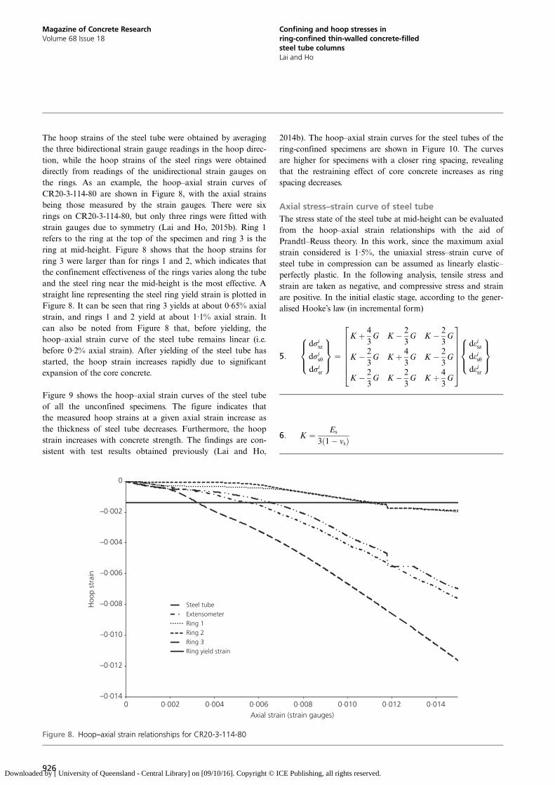
The hoop strains of the steel tube were obtained by averagingthe three bidirectional strain gauge readings in the hoop direc-tion, while the hoop strains of the steel rings were obtaineddirectly from readings of the unidirectional strain gauges onthe rings. As an example, the hoop–axial strain curves ofCR20-3-114-80 are shown in Figure 8, with the axial strainsbeing those measured by the strain gauges. There were sixrings on CR20-3-114-80, but only three rings were fitted withstrain gauges due to symmetry (Lai and Ho, 2015b). Ring 1refers to the ring at the top of the specimen and ring 3 is thering at mid-height. Figure 8 shows that the hoop strains forring 3 were larger than for rings 1 and 2, which indicates thatthe confinement effectiveness of the rings varies along the tubeand the steel ring near the mid-height is the most effective. Astraight line representing the steel ring yield strain is plotted inFigure 8. It can be seen that ring 3 yields at about 0·65% axialstrain, and rings 1 and 2 yield at about 1·1% axial strain. Itcan also be noted from Figure 8 that, before yielding, thehoop–axial strain curve of the steel tube remains linear (i.e.before 0·2% axial strain). After yielding of the steel tube hasstarted, the hoop strain increases rapidly due to significantexpansion of the core concrete.
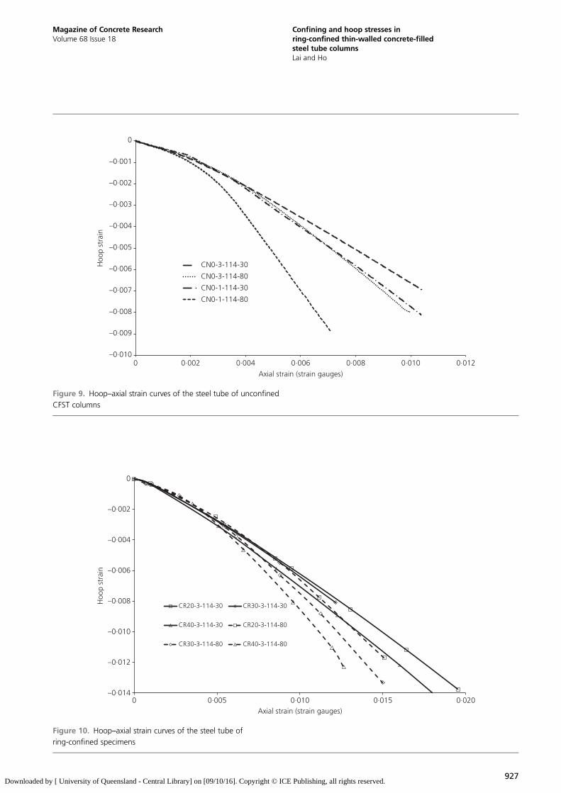
Figure 9 shows the hoop–axial strain curves of the steel tubeof all the unconfined specimens. The figure indicates thatthe measured hoop strains at a given axial strain increase asthe thickness of steel tube decreases. Furthermore, the hoopstrain increases with concrete strength. The findings are con-sistent with test results obtained previously (Lai and Ho,
2014b). The hoop–axial strain curves for the steel tubes of thering-confined specimens are shown in Figure 10. The curvesare higher for specimens with a closer ring spacing, revealingthat the restraining effect of core concrete increases as ringspacing decreases.
Axial stress–strain curve of steel tubeThe stress state of the steel tube at mid-height can be evaluatedfrom the hoop–axial strain relationships with the aid ofPrandtl–Reuss theory. In this work, since the maximum axialstrain considered is 1·5%, the uniaxial stress–strain curve ofsteel tube in compression can be assumed as linearly elastic–perfectly plastic. In the following analysis, tensile stress andstrain are taken as negative, and compressive stress and strainare positive. In the initial elastic stage, according to the gener-alised Hooke’s law (in incremental form)
5:
dσiszdσisθdσisr
8><>:
9>=>; ¼
K þ 43G K � 2
3G K � 2
3G
K � 23G K þ 4
3G K � 2
3G
K � 23G K � 2
3G K þ 4
3G
26666664
37777775
dεiszdεisθdεisr
8><>:
9>=>;
6: K ¼ Es
3ð1� νsÞ
–0·014
–0·012
–0·010
–0·008
–0·006
–0·004
–0·002
0
0 0·002 0·004 0·006 0·008 0·010 0·012 0·014
Hoo
p st
rain
Axial strain (strain gauges)
Steel tubeExtensometerRing 1Ring 2Ring 3Ring yield strain
Figure 8. Hoop–axial strain relationships for CR20-3-114-80
926
Magazine of Concrete ResearchVolume 68 Issue 18
Confining and hoop stresses inring-confined thin-walled concrete-filledsteel tube columnsLai and Ho
Downloaded by [ University of Queensland - Central Library] on [09/10/16]. Copyright © ICE Publishing, all rights reserved.
–0·010
–0·009
–0·008
–0·007
–0·006
–0·005
–0·004
–0·003
–0·002
–0·001
0
0 0·002 0·004 0·006 0·008 0·010 0·012
Hoo
p st
rain
Axial strain (strain gauges)
CN0-3-114-30
CN0-3-114-80
CN0-1-114-30
CN0-1-114-80
Figure 9. Hoop–axial strain curves of the steel tube of unconfined
CFST columns
–0·014
–0·012
–0·010
–0·008
–0·006
–0·004
–0·002
0
0 0·005 0·010 0·015 0·020
Hoo
p st
rain
Axial strain (strain gauges)
CR20-3-114-30 CR30-3-114-30
CR40-3-114-30 CR20-3-114-80
CR30-3-114-80 CR40-3-114-80
Figure 10. Hoop–axial strain curves of the steel tube of
ring-confined specimens
927
Magazine of Concrete ResearchVolume 68 Issue 18
Confining and hoop stresses inring-confined thin-walled concrete-filledsteel tube columnsLai and Ho
Downloaded by [ University of Queensland - Central Library] on [09/10/16]. Copyright © ICE Publishing, all rights reserved.
7: G ¼ Es
2ð1þ νsÞ
During the plastic stage, the famous Prandtl–Reuss equationsare adopted
For a perfectly plastic material
9: ω ¼ 3Gσ2sy
For CFST columns with a thin-walled steel tube, it is reason-able to ignore the small radial stress (σsr) of the steel tube.Thus, the steel tube can be assumed to be in plane stress andthe above equations become
10:dσiszdσisθ
( )¼ Es
1� νs
1 νsνs 1
� �dεiszdεisθ
( )
During the plastic stage, the incremental form of the stress–strain relationship should be used
11:dσiszdσisθ
( )¼ Es
S2z þ S2
θ þ 2νsSzSθ
S2θ �SzSθ
�SzSθ S2z
" #dεiszdεisθ
( )
In particular,
12: Sz ¼ 13
2σi�1sz � σi�1
sθ
� �
13: Sθ ¼ 13
2σi�1sθ � σi�1
sz
� �
In the above equations, σsz, σsθ and σsr respectively refer to theaxial, hoop and radial stresses of steel tube, K and G are thebulk and shear moduli of the steel tube, νs is Poisson’s ratio ofthe steel tube (taken as 0·3 in this paper), εsz, εsθ and εsr arerespectively the axial, hoop and radial strains of the steel tube,ω is the hardening parameter, Sz, Sθ and Sr respectively referto the deviatoric stresses in axial, hoop and radial directions
and i is the present stress or strain increment number. Theyield surface of the steel tube is determined by the von Misesyield criterion
14: σ2sz � σszσsθ þ σ2sθ ¼ σ2sy
The stresses in the steel tube can be studied using Equations10–14 and the hoop–axial strain curves of the specimens. Toeliminate measurement noise of the loading machine,smoothed hoop–axial strain relationships should be adopted(Hu et al., 2011) for the steel tube.
The calculated axial stress–strain curves for the steel tubesusing Equations 10–14 are shown in Figure 11, in which theaxial strains are the modified LVDT readings. All the curves inFigure 11 stop at 1·5% axial strain except CN0-3-114-30 andCN0-1-114-80; these curves stop earlier due to a technicalproblem with the testing machine and low ductility, respect-ively. Figure 11 shows that the axial stress increases linearly asaxial strain increases until it is slightly higher than the steelyield stress. The difference between the largest axial stressobtained and the steel yield stress is due to the different dilata-tional properties of the steel tube and the concrete, resulting inpositive hoop stress (compression) at the initial loading stageand hence the larger value of axial stress. For the ring-confinedspecimens, the confining effect of the rings may also increasethe axial stress of the steel tubes. As axial strain increases, theaxial stress drops for all the specimens after the peak pointbecause concrete dilates more than the steel tube, leading tonegative hoop stress (tension) and a drop in axial stress.Interestingly, it can be seen from Figure 11 that the axial stressdegrades more rapidly in columns filled with HSC rather thanNSC, which is because HSC dilates more than NSC and theconfining stress provided at a given axial strain is larger. Dueto the confining effect provided by the steel rings, the axialstress drops more gradually for the ring-confined specimens.On the other hand, at a given concrete strength, the axialstress drops more rapidly as the tube thickness decreases. Inparticular, the axial stress of CN0-1-114-80 drops almost tozero at an axial strain of 0·008, which is due to the local buck-ling that occurred near the bottom surface as shown inFigure 6(c).
Curves of calculated hoop stress against axial strain (by modi-fied LVDT readings) are plotted in Figure 12. For all the
8:
dσisz
dσisθ
dσisr
8>><>>:
9>>=>>; ¼
K þ 43G � ωS2
z K � 23G � ωSzSθ K � 2
3G � ωSzSr
K � 23G � ωSzSθ K þ 4
3G � ωS2
θ K � 23G � ωSθSr
K � 23G � ωSzSr K � 2
3G � ωSθSr K þ 4
3G � ωS2
r
266666664
377777775
dεisz
dεisθ
dεisr
8>><>>:
9>>=>>;
928
Magazine of Concrete ResearchVolume 68 Issue 18
Confining and hoop stresses inring-confined thin-walled concrete-filledsteel tube columnsLai and Ho
Downloaded by [ University of Queensland - Central Library] on [09/10/16]. Copyright © ICE Publishing, all rights reserved.
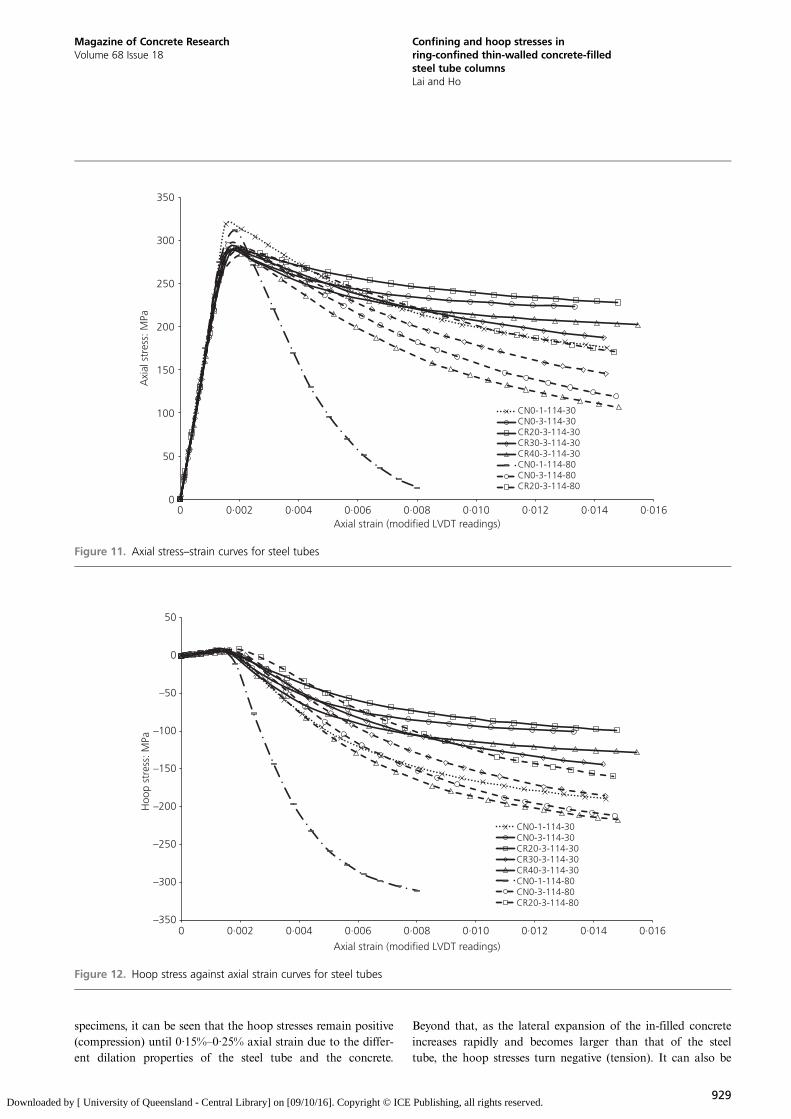
specimens, it can be seen that the hoop stresses remain positive(compression) until 0·15%–0·25% axial strain due to the differ-ent dilation properties of the steel tube and the concrete.
Beyond that, as the lateral expansion of the in-filled concreteincreases rapidly and becomes larger than that of the steeltube, the hoop stresses turn negative (tension). It can also be
0
50
100
150
200
250
300
350
0 0·002 0·004 0·006 0·008 0·010 0·012 0·014 0·016
Axi
al s
tres
s: M
Pa
Axial strain (modified LVDT readings)
CN0-1-114-30CN0-3-114-30CR20-3-114-30CR30-3-114-30CR40-3-114-30CN0-1-114-80CN0-3-114-80CR20-3-114-80
Figure 11. Axial stress–strain curves for steel tubes
–350
–300
–250
–200
–150
–100
–50
0
50
0 0·002 0·004 0·006 0·008 0·010 0·012 0·014 0·016
Axial strain (modified LVDT readings)
CN0-1-114-30CN0-3-114-30CR20-3-114-30CR30-3-114-30CR40-3-114-30CN0-1-114-80CN0-3-114-80CR20-3-114-80
Hoo
p st
ress
: MPa
Figure 12. Hoop stress against axial strain curves for steel tubes
929
Magazine of Concrete ResearchVolume 68 Issue 18
Confining and hoop stresses inring-confined thin-walled concrete-filledsteel tube columnsLai and Ho
Downloaded by [ University of Queensland - Central Library] on [09/10/16]. Copyright © ICE Publishing, all rights reserved.
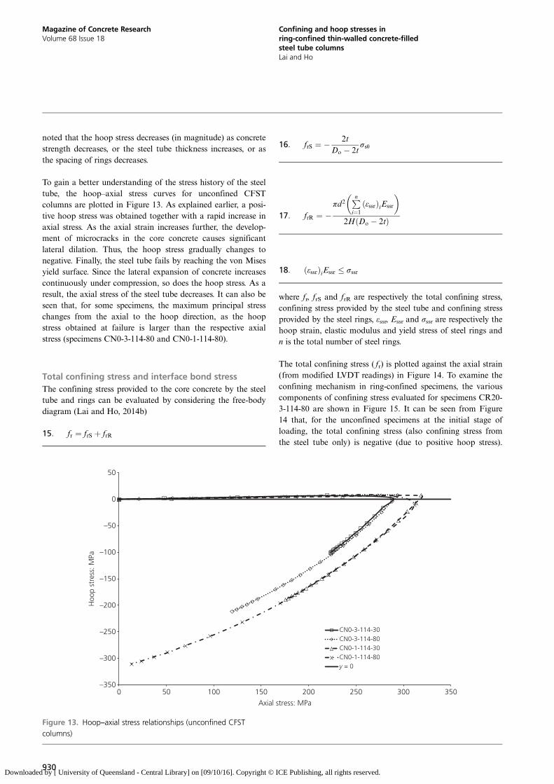
noted that the hoop stress decreases (in magnitude) as concretestrength decreases, or the steel tube thickness increases, or asthe spacing of rings decreases.
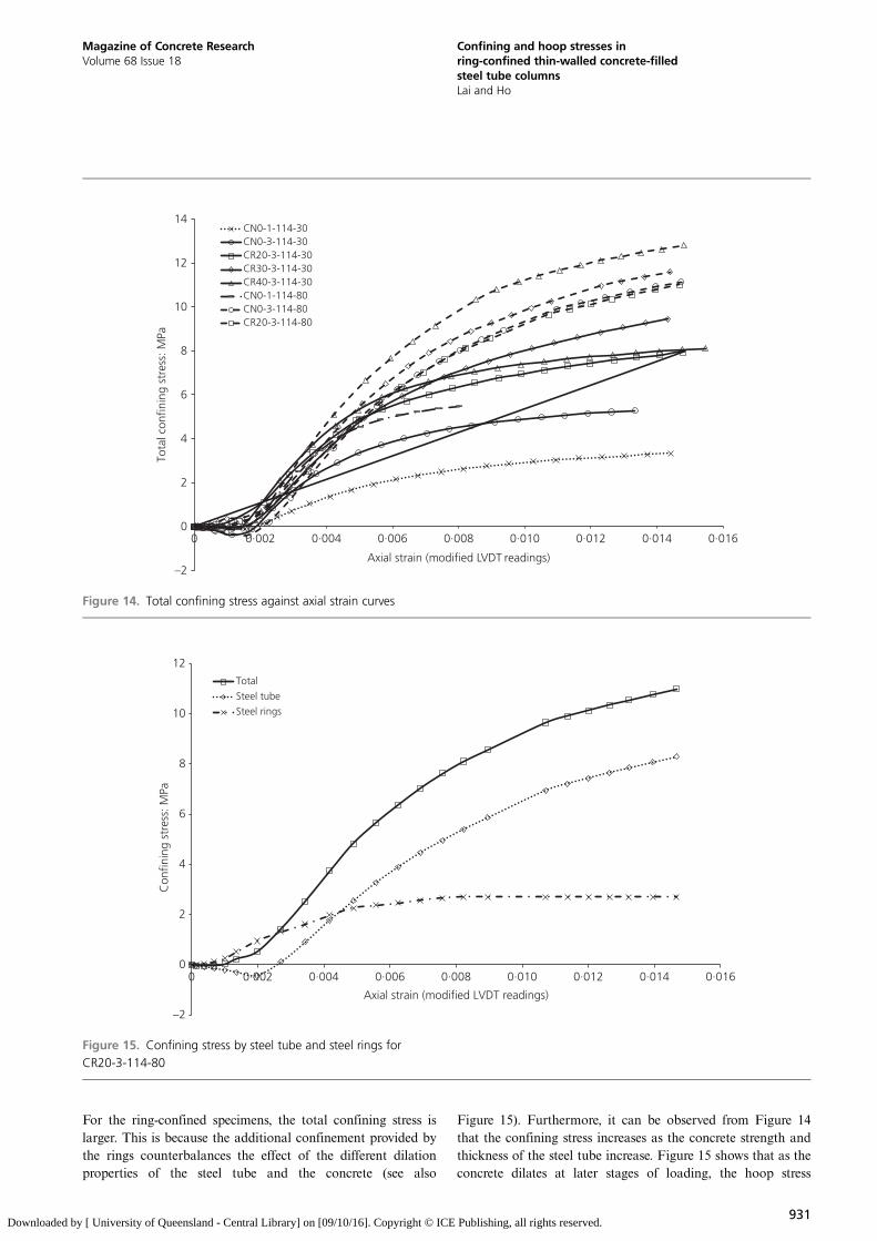
To gain a better understanding of the stress history of the steeltube, the hoop–axial stress curves for unconfined CFSTcolumns are plotted in Figure 13. As explained earlier, a posi-tive hoop stress was obtained together with a rapid increase inaxial stress. As the axial strain increases further, the develop-ment of microcracks in the core concrete causes significantlateral dilation. Thus, the hoop stress gradually changes tonegative. Finally, the steel tube fails by reaching the von Misesyield surface. Since the lateral expansion of concrete increasescontinuously under compression, so does the hoop stress. As aresult, the axial stress of the steel tube decreases. It can also beseen that, for some specimens, the maximum principal stresschanges from the axial to the hoop direction, as the hoopstress obtained at failure is larger than the respective axialstress (specimens CN0-3-114-80 and CN0-1-114-80).
Total confining stress and interface bond stressThe confining stress provided to the core concrete by the steeltube and rings can be evaluated by considering the free-bodydiagram (Lai and Ho, 2014b)
15: fr ¼ frS þ frR
16: frS ¼ � 2tDo � 2t
σsθ
17: frR ¼ �πd2 Pn
i¼1ðεssrÞiEssr
� �2HðDo � 2tÞ
18: ðεssrÞiEssr � σssr
where fr, frS and frR are respectively the total confining stress,confining stress provided by the steel tube and confining stressprovided by the steel rings, εssr, Essr and σssr are respectively thehoop strain, elastic modulus and yield stress of steel rings andn is the total number of steel rings.
The total confining stress ( fr) is plotted against the axial strain(from modified LVDT readings) in Figure 14. To examine theconfining mechanism in ring-confined specimens, the variouscomponents of confining stress evaluated for specimens CR20-3-114-80 are shown in Figure 15. It can be seen from Figure14 that, for the unconfined specimens at the initial stage ofloading, the total confining stress (also confining stress fromthe steel tube only) is negative (due to positive hoop stress).
–350
–300
–250
–200
–150
Hoo
p st
ress
: MPa –100
–50
0
50
0 50 100 150 200 250 300 350
Axial stress: MPa
CN0-3-114-30CN0-3-114-80CN0-1-114-30CN0-1-114-80y = 0
Figure 13. Hoop–axial stress relationships (unconfined CFST
columns)
930
Magazine of Concrete ResearchVolume 68 Issue 18
Confining and hoop stresses inring-confined thin-walled concrete-filledsteel tube columnsLai and Ho
Downloaded by [ University of Queensland - Central Library] on [09/10/16]. Copyright © ICE Publishing, all rights reserved.
For the ring-confined specimens, the total confining stress islarger. This is because the additional confinement provided bythe rings counterbalances the effect of the different dilationproperties of the steel tube and the concrete (see also
Figure 15). Furthermore, it can be observed from Figure 14that the confining stress increases as the concrete strength andthickness of the steel tube increase. Figure 15 shows that as theconcrete dilates at later stages of loading, the hoop stress
–2
0
2
4
6
8
10
12
14
0 0·002 0·004 0·006 0·008 0·010 0·012 0·014 0·016
Tota
l con
finin
g st
ress
: MPa
Axial strain (modified LVDT readings)
CN0-1-114-30CN0-3-114-30CR20-3-114-30CR30-3-114-30CR40-3-114-30CN0-1-114-80CN0-3-114-80CR20-3-114-80
Figure 14. Total confining stress against axial strain curves
–2
0
2
4
6
Con
finin
g st
ress
: MPa
8
10
12
0 0·002 0·004 0·006 0·008 0·010 0·012 0·014 0·016
Axial strain (modified LVDT readings)
Total
Steel tube
Steel rings
Figure 15. Confining stress by steel tube and steel rings for
CR20-3-114-80
931
Magazine of Concrete ResearchVolume 68 Issue 18
Confining and hoop stresses inring-confined thin-walled concrete-filledsteel tube columnsLai and Ho
Downloaded by [ University of Queensland - Central Library] on [09/10/16]. Copyright © ICE Publishing, all rights reserved.
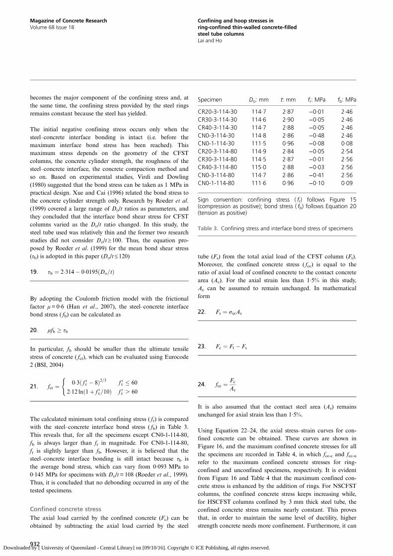
becomes the major component of the confining stress and, atthe same time, the confining stress provided by the steel ringsremains constant because the steel has yielded.
The initial negative confining stress occurs only when thesteel–concrete interface bonding is intact (i.e. before themaximum interface bond stress has been reached). Thismaximum stress depends on the geometry of the CFSTcolumns, the concrete cylinder strength, the roughness of thesteel–concrete interface, the concrete compaction method andso on. Based on experimental studies, Virdi and Dowling(1980) suggested that the bond stress can be taken as 1 MPa inpractical design. Xue and Cai (1996) related the bond stress tothe concrete cylinder strength only. Research by Roeder et al.(1999) covered a large range of Do/t ratios as parameters, andthey concluded that the interface bond shear stress for CFSTcolumns varied as the Do/t ratio changed. In this study, thesteel tube used was relatively thin and the former two researchstudies did not consider Do/t ≥ 100. Thus, the equation pro-posed by Roeder et al. (1999) for the mean bond shear stress(τb) is adopted in this paper (Do/t ≤ 120)
19: τb ¼ 2�314� 0�0195ðDo=tÞ
By adopting the Coulomb friction model with the frictionalfactor μ=0·6 (Han et al., 2007), the steel–concrete interfacebond stress ( fb) can be calculated as
20: μfb � τb
In particular, fb should be smaller than the ultimate tensilestress of concrete ( fct), which can be evaluated using Eurocode2 (BSI, 2004)
21: fct ¼ 0�3 f 0c � 8ð Þ2=3 f 0c � 60
2�12 ln 1þ f 0c=10ð Þ f 0c . 60
(
The calculated minimum total confining stress ( fr) is comparedwith the steel–concrete interface bond stress ( fb) in Table 3.This reveals that, for all the specimens except CN0-1-114-80,fb is always larger than fr in magnitude. For CN0-1-114-80,fr is slightly larger than fb. However, it is believed that thesteel–concrete interface bonding is still intact because τb isthe average bond stress, which can vary from 0·093 MPa to0·145 MPa for specimens with Do/t=108 (Roeder et al., 1999).Thus, it is concluded that no debonding occurred in any of thetested specimens.
Confined concrete stressThe axial load carried by the confined concrete (Fc) can beobtained by subtracting the axial load carried by the steel
tube (Fs) from the total axial load of the CFST column (Ft).Moreover, the confined concrete stress ( fcc) is equal to theratio of axial load of confined concrete to the contact concretearea (Ac). For the axial strain less than 1·5% in this study,Ac can be assumed to remain unchanged. In mathematicalform
22: Fs ¼ σszAs
23: Fc ¼ Ft � Fs
24: fcc ¼ Fc
Ac
It is also assumed that the contact steel area (As) remainsunchanged for axial strain less than 1·5%.
Using Equation 22–24, the axial stress–strain curves for con-fined concrete can be obtained. These curves are shown inFigure 16, and the maximum confined concrete stresses for allthe specimens are recorded in Table 4, in which fcc-c and fcc-urefer to the maximum confined concrete stresses for ring-confined and unconfined specimens, respectively. It is evidentfrom Figure 16 and Table 4 that the maximum confined con-crete stress is enhanced by the addition of rings. For NSCFSTcolumns, the confined concrete stress keeps increasing while,for HSCFST columns confined by 3 mm thick steel tube, theconfined concrete stress remains nearly constant. This provesthat, in order to maintain the same level of ductility, higherstrength concrete needs more confinement. Furthermore, it can
Specimen Do: mm t: mm fr: MPa fb: MPa
CR20-3-114-30 114·7 2·87 −0·01 2·46CR30-3-114-30 114·6 2·90 −0·05 2·46CR40-3-114-30 114·7 2·88 −0·05 2·46CN0-3-114-30 114·8 2·86 −0·48 2·46CN0-1-114-30 111·5 0·96 −0·08 0·08CR20-3-114-80 114·9 2·84 −0·05 2·54CR30-3-114-80 114·5 2·87 −0·01 2·56CR40-3-114-80 115·0 2·88 −0·03 2·56CN0-3-114-80 114·7 2·86 −0·41 2·56CN0-1-114-80 111·6 0·96 −0·10 0·09
Sign convention: confining stress ( fr) follows Figure 15(compression as positive); bond stress ( fb) follows Equation 20(tension as positive)
Table 3. Confining stress and interface bond stress of specimens
932
Magazine of Concrete ResearchVolume 68 Issue 18
Confining and hoop stresses inring-confined thin-walled concrete-filledsteel tube columnsLai and Ho
Downloaded by [ University of Queensland - Central Library] on [09/10/16]. Copyright © ICE Publishing, all rights reserved.
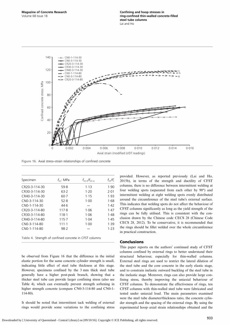
be observed from Figure 16 that the difference in the initialelastic portion for the same concrete cylinder strength is small,indicating little effect of steel tube thickness at this stage.However, specimens confined by the 3 mm thick steel tubegenerally have a higher post-peak branch, showing that athicker steel tube can provide larger confining stress (also seeTable 4), which can eventually prevent strength softening inhigher strength concrete (compare CN0-3-114-80 and CN0-1-114-80).
It should be noted that intermittent tack welding of externalrings would provide some variations to the confining stress
provided. However, as reported previously (Lai and Ho,2015b), in terms of the strength and ductility of CFSTcolumns, there is no difference between intermittent welding atfour welding spots (separated from each other by 90°) andintermittent welding at eight welding spots evenly distributedaround the circumference of the steel tube’s external surface.This indicates that welding spots do not affect the behaviour ofCFST columns significantly as long as the yield strength of therings can be fully utilised. This is consistent with the con-clusion drawn by the Chinese code CECS 28 (Chinese CodeCECS 28, 2012). To be conservative, it is recommended thatthe rings should be fillet welded over the whole circumferencein practical construction.
ConclusionsThis paper reports on the authors’ continued study of CFSTcolumns confined by external rings to better understand theirstructural behaviour, especially for thin-walled columns.External steel rings are used to restrict the lateral dilation ofthe steel tube and the core concrete in the early elastic stage,and to constrain inelastic outward buckling of the steel tube inthe inelastic stage. Moreover, rings can also provide large con-fining stress, thereby improving the uniaxial behaviour ofCFST columns. To demonstrate the effectiveness of rings, tenCFST columns with thin-walled steel tube were fabricated andtested under uniaxial load. The main parameters examinedwere the steel tube diameter/thickness ratio, the concrete cylin-der strength and the spacing of the external rings. By using theexperimental hoop–axial strain relationships obtained and the
0
20
40
60
80
100
120
140
0 0·002 0·004 0·006 0·008 0·010 0·012 0·014 0·016
Axial strain (modified LVDT readings)
CN0-1-114-30CN0-3-114-30CR20-3-114-30CR30-3-114-30CR40-3-114-30CN0-1-114-80CN0-3-114-80CR20-3-114-80
Con
fined
con
cret
e st
ress
: MPa
Figure 16. Axial stress–strain relationships of confined concrete
Specimen fcc: MPa fcc-c/fcc-u fcc/f 0c
CR20-3-114-30 59·8 1·13 1·90CR30-3-114-30 63·2 1·20 2·01CR40-3-114-30 60·7 1·15 1·93CN0-3-114-30 52·8 1·00 1·68CN0-1-114-30 44·6 — 1·42CR20-3-114-80 117·8 1·06 1·47CR30-3-114-80 118·1 1·06 1·48CR40-3-114-80 115·7 1·04 1·45CN0-3-114-80 111·1 1·00 1·39CN0-1-114-80 98·2 — 1·23
Table 4. Strength of confined concrete in CFST columns
933
Magazine of Concrete ResearchVolume 68 Issue 18
Confining and hoop stresses inring-confined thin-walled concrete-filledsteel tube columnsLai and Ho
Downloaded by [ University of Queensland - Central Library] on [09/10/16]. Copyright © ICE Publishing, all rights reserved.
Prandtl–Reuss theory for thin-walled steel tubes, the true struc-tural behaviour of CFST columns was studied. The experimen-tal and analytical studies indicate the following.
& Due to the supporting effect provided by the core concrete,the buckling resistance of thin-walled steel tubes isimproved.
& External rings are highly effective in improving thestrength, elastic stiffness, ductility and the interfacebonding condition of CFST columns.
& For unconfined CFST columns, the failure mode is ‘endeffect’ type buckling; due to the confining effect of externalrings, the failure mode of ring-confined CFST columns isoutward folding between two adjacent rows of steel rings.
& Attributed to the different dilation properties of steel andconcrete, the total confining stress is negative for uncon-fined CFST columns (i.e. debonding occurs). The provisionof external rings can counterbalance the debonding stressat the initial stage and improve the uniaxial performanceof CFST columns.
& The total confining stress increases as the thickness of thesteel tube or concrete strength increases.
This study provides a link between the authors’ previous exper-imental and theoretical studies on the stress–strain behaviourof CFST columns. Some observations on the hoop–axial strainbehaviour (e.g. measured hoop strains at a given axial strainincrease as the thickness of the steel tube decreases, hoopstrains increase with concrete strength, and hoop–axial straincurves are higher for specimens with closer ring spacings) areimportant findings for the development of a theoretical stress–strain model for confined CFST columns, which will be pre-sented in future work.
AcknowledgementsThe work described in this paper was substantially supportedby a grant from the Research Grants Council of the HongKong Special Administrative Region, China (project no. HKU712310E). Technical support for the experimental tests pro-vided by the laboratory staff of the Department of CivilEngineering, The University of Hong Kong, is gratefullyacknowledged.
REFERENCES
Bradford MA, Loh HY and Uy B (2002) Slenderness limits forfilled circular steel tubes. Journal of Constructional SteelResearch 58(2): 243–252.
BSI (1983a) BS 1881-110: 1983: Testing concrete. Method formaking test cylinders from fresh concrete. BSI, London,UK.
BSI (1983b) BS 1881-120:1983: Testing concrete. Method fordetermination of the compressive strength of concretecores. BSI, London, UK.
BSI (1983c) BS 1881-121: 1983: Testing concrete. Method fordetermination of static modulus of elasticity incompression. BSI, London, UK.
BSI (1993) BS EN 1993-1-1: Eurocode 3: Design of steelstructures. Part 1-1: General rules and rules for buildings.BSI, London, UK.
BSI (2004) BS EN 1992-1-1: Eurocode 2: Design of concretestructures. Part 1-1: General rules and rules for buildings.BSI, London, UK.
BSI (2009) BS EN ISO 6892-1: 2009: Metallic materials.Tensile testing. Method of test at ambient temperature.BSI, London, UK.
Cai J and He ZQ (2006) Axial load behavior of square CFT stubcolumn with binding bars. Journal of Constructional SteelResearch 62(5): 472–483.
Chinese Code (2012) CECS 28: Technical specification forconcrete-filled steel tubular structures. Chinese EngineeringConstruction Society, China Planning Press, Beijing, China(in Chinese).
Dabaon M, El-Khoriby S, El-Boghdadi M and Hassanein MF
(2009) Confinement effect of stiffened and unstiffenedconcrete-filled stainless steel tubular stub columns. Journalof Constructional Steel Research 65(8): 1846–1854.
Ganesh Prabhu G and Sundarraja M (2013) Behaviour ofconcrete filled steel tubular (CFST) short columnsexternally reinforced using CFRP strips composite.Construction and Building Materials 47: 1362–1371.
Han LH, Yao GH and Zhao XL (2005) Tests and calculationsfor hollow structural steel (HSS) stub columns filled withself-consolidating concrete (SCC). Journal ofConstructional Steel Research 61(9): 1241–1269.
Han LH, Yao GH and Tao Z (2007) Performance ofconcrete-filled thin-walled steel tubes under pure torsion.Thin-Walled Structures 45(1): 24–36.
Hancock GJ (1998) Design of Cold-formed Steel Structures toAustralian/New Zealand Standard AS/NZS 4600:1996.Australian Institute of Steel Construction, Sydney, NSW,Australia.
Ho JCM and Lai MH (2013) Behaviour of uni-axially loadedCFST columns confined by tie bars. Journal ofConstructional Steel Research 83: 37–50.
Ho JCM, Au FTK and Kwan AKH (2005) Effects of strainhardening of steel reinforcement on flexural strength andductility of concrete beams. Structural Engineering andMechanics 19(2): 185–198.
Ho JCM,Lai MH and Luo L (2014) Uni-axial behaviour ofconfined high-strength CFST columns. Proceedings of theInstitution of Civil Engineers – Structures and Buildings167(9): 520–533, http://dx.doi.org/10.1680/stbu.13.00004.
Hu YM, Yu T and Teng JG (2011) FRP-confined circularconcrete-filled thin steel tubes under axial compression.Journal of Composites for Construction 15(5):850–860.
Huang Y and Young B (2014) The art of coupon tests. Journalof Constructional Steel Research 96: 159–175.
934
Magazine of Concrete ResearchVolume 68 Issue 18
Confining and hoop stresses inring-confined thin-walled concrete-filledsteel tube columnsLai and Ho
Downloaded by [ University of Queensland - Central Library] on [09/10/16]. Copyright © ICE Publishing, all rights reserved.
Huang CS, Yeh YK, Liu GY et al. (2002) Axial load behavior ofstiffened concrete-filled steel columns. Journal of StructuralEngineering 128(9): 1222–1230.
Lai MH and Ho JCM (2014a) Behaviour of uni-axially loadedconcrete-filled-steel-tube columns confined by externalrings. The Structural Design of Tall and Special Buildings23(6): 403–426.
Lai MH and Ho JCM (2014b) Confinement effect of ring-confined concrete-filled-steel-tube columns under uni-axialload. Engineering Structures 67: 123–141.
Lai MH and Ho JCM (2015a) Effect of continuous spirals onuni-axial strength and ductility of CFST columns. Journalof Constructional Steel Research 104: 235–249.
Lai MH and Ho JCM (2015b) Optimal design of external ringsfor confined CFST columns. Magazine of ConcreteResearch 67(19): 1017–1032, http://dx.doi.org/10.1680/macr.14.00348.
Law K and Gardner L (2012) Lateral instability of ellipticalhollow section beams. Engineering Structures 37: 152–166.
Lu X and Hsu CTT (2007) Tangent Poisson’s ratio of high-strength concrete in triaxial compression. Magazine ofConcrete Research 59(1): 69–77, http://dx.doi.org/10.1680/macr.2007.59.1.69.
O’Shea MD and Bridge RQ (2000) Design of circular thin-walled concrete filled steel tubes. Journal of StructuralEngineering 126(11): 1295–1303.
Petrus C, Hamid HA, Ibrahim A and Parke G (2010)Experimental behaviour of concrete filled thin walled steeltubes with tab stiffeners. Journal of Constructional SteelResearch 66(7): 915–922.
Roeder CW, Cameron B and Brown CB (1999) Composite actionin concrete filled tubes. Journal of Structural Engineering125(5): 477–484.
Tao Z, Han LH and Wang DY (2008) Strength and ductility ofstiffened thin-walled hollow steel structural stub columnsfilled with concrete. Thin-Walled Structures 46(10):1113–1128.
Uy B (1998) Local and post-local buckling of concrete filledsteel welded box columns. Journal of Constructional SteelResearch 47(1–2): 47–72.
Uy B (2001) Strength of short concrete filled high strength steelbox columns. Journal of Constructional Steel Research57(2): 113–134.
Uy B and Das S (1997) Wet concrete loading of thin-walledsteel box columns during the construction of a tallbuilding. Journal of Constructional Steel Research 42(2):95–119.
Uy B, Tao Z and Han LH (2011) Behaviour of short andslender concrete-filled stainless steel tubularcolumns. Journal of Constructional Steel Research 67(3):360–378.
Virdi KS and Dowling PJ (1980) Bond strength in concrete filledsteel tubes. IABSE Periodica 3: 125–139.
Xue LH and Cai SH (1996) Bond strength at the interface ofconcrete-filled steel tube columns. Building Science3: 22–28 (in Chinese).
Young B and Ellobody E (2006) Experimental investigation ofconcrete-filled cold-formed high strength stainless steeltube columns. Journal of Constructional Steel Research62(5): 484–492.
Yu ZW, Ding FX and Cai CS (2007) Experimental behavior ofcircular concrete-filled steel tube stub columns. Journal ofConstructional Steel Research 63(2): 165–174.
Zhong ST (2006) Unified Theory of CFST Structures: Researchand Application, 1st edn. Tsinghua University Press,Beijing, China (in Chinese).
HOW CAN YOU CONTRIBUTE?
To discuss this paper, please submit up to 500 words tothe editor at [email protected]. Your contribution willbe forwarded to the author(s) for a reply and, if con-sidered appropriate by the editorial board, it will be pub-lished as a discussion in a future issue of the journal.
935
Magazine of Concrete ResearchVolume 68 Issue 18
Confining and hoop stresses inring-confined thin-walled concrete-filledsteel tube columnsLai and Ho
Downloaded by [ University of Queensland - Central Library] on [09/10/16]. Copyright © ICE Publishing, all rights reserved.