Embed Size (px)
Citation preview
00016-79200-01 1 Keyless Entry Control Module00016-34030-05 2 Keyless Entry Transmitter00016-32901-01 1 Main Wiring Harness00016-30960-56 1 On/Off Toggle Control Switch00016-32901-02 1 Miscellaneous Hardware Kit00016-30960-09 1 34" Headlight Extension Wire
P/N Qty Description
Phillip screwdriver Straight-Slot screwdriverRatchet w/extension 10 mm socketDiagonal wire cutters Common pliersFlashlight Nylon trim tool7/16” Comb. wrenchTorque Wrench 36in. lbs.
Kit Contents
Hardware Bag Contents
General Applicability
Recommended Tools
Safety Tools
Special Tools
INSTALLATION TOOLS
Special Chemicals
Vehicle Service Parts (may be required for reassembly)
Item # Quantity Reqd Description1 1 Keyless Module2 1 Main Harness3 1 Hardware Bag4 1 Valet Switch5 2 24" Cable Ties6 2 3-Button Transmitter
Item # Quantity Reqd Description1 8 Red T-Taps2 2 Blue T-Taps3 6 8" Cable Ties4 1 2-1/4"x 2-1/4" Foam Pad5 1 Yellow T-Tap
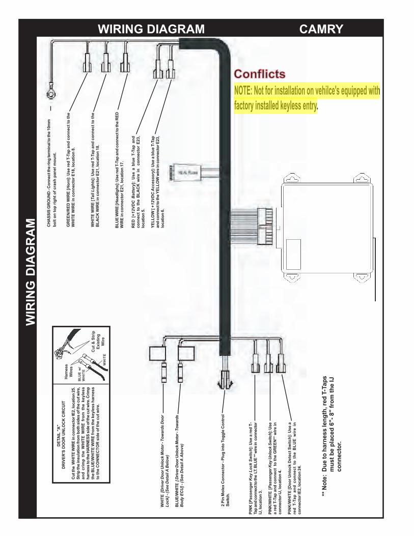
NOTE: Not for installation on vehilce's equipped withfactory installed keyless entry.
Power door locks required
Toyota Camry 2011 - Keyless Entry System
Part Number: 00016-32901Code: KE1
Southeast Toyota Distributors, LLC Page 1 of 10
Conflicts

TOYOTA CAMRY KEYLESS ENTRY SYSTEM
Negative Battery
PLASTIC NUT
REMOVE THE DRIVER'S SIDE KICK PANEL:
REMOVE THE DRIVER'S SIDE SCUFF PLATE:
REMOVE THE UPPER DASH PANEL:
INSTALLATION PREPARATION
Before starting installation1. Familiarize yourself with the installationinstructions.
2. Inspect kit components (Refer to kitcontents and hardware bag contents).
VEHICLE PREPARATION
1. Place protective coverings on vehicle.
2. "IMPORTANT........IMPORTANT" Disconnect Negative Battery Cable
1. Refer to the vehicle repair manual, andcarefully remove front kick panel.
1. Refer to the vehicle repair manual, andcarefully remove front scuff plate.
1. Refer to the vehicle repair manual, andcarefully remove the driver's side upper dashpanel.
Southeast Toyota Distributors, LLC Page 2 of 10
TOYOTA CAMRY KEYLESS ENTRY SYSTEM
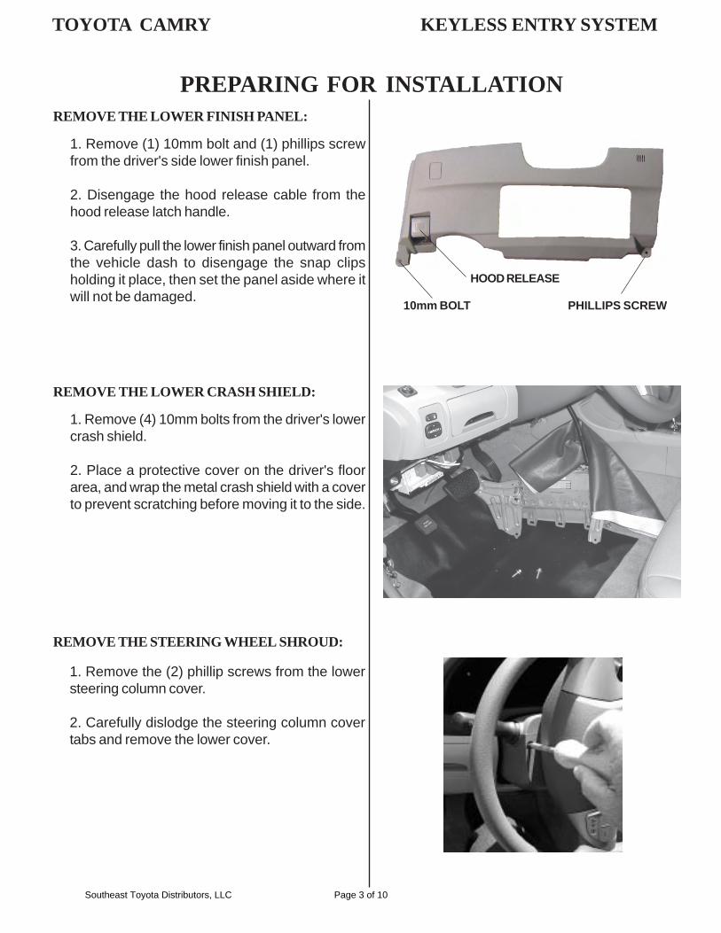
REMOVE THE LOWER FINISH PANEL:
1. Remove (1) 10mm bolt and (1) phillips screwfrom the driver's side lower finish panel.
2. Disengage the hood release cable from thehood release latch handle.
3. Carefully pull the lower finish panel outward fromthe vehicle dash to disengage the snap clipsholding it place, then set the panel aside where itwill not be damaged.
10mm BOLT PHILLIPS SCREW
HOOD RELEASE
REMOVE THE LOWER CRASH SHIELD:
1. Remove (4) 10mm bolts from the driver's lowercrash shield.
2. Place a protective cover on the driver's floorarea, and wrap the metal crash shield with a coverto prevent scratching before moving it to the side.
PREPARING FOR INSTALLATION
REMOVE THE STEERING WHEEL SHROUD:
1. Remove the (2) phillip screws from the lowersteering column cover.
2. Carefully dislodge the steering column covertabs and remove the lower cover.
Southeast Toyota Distributors, LLC Page 3 of 10
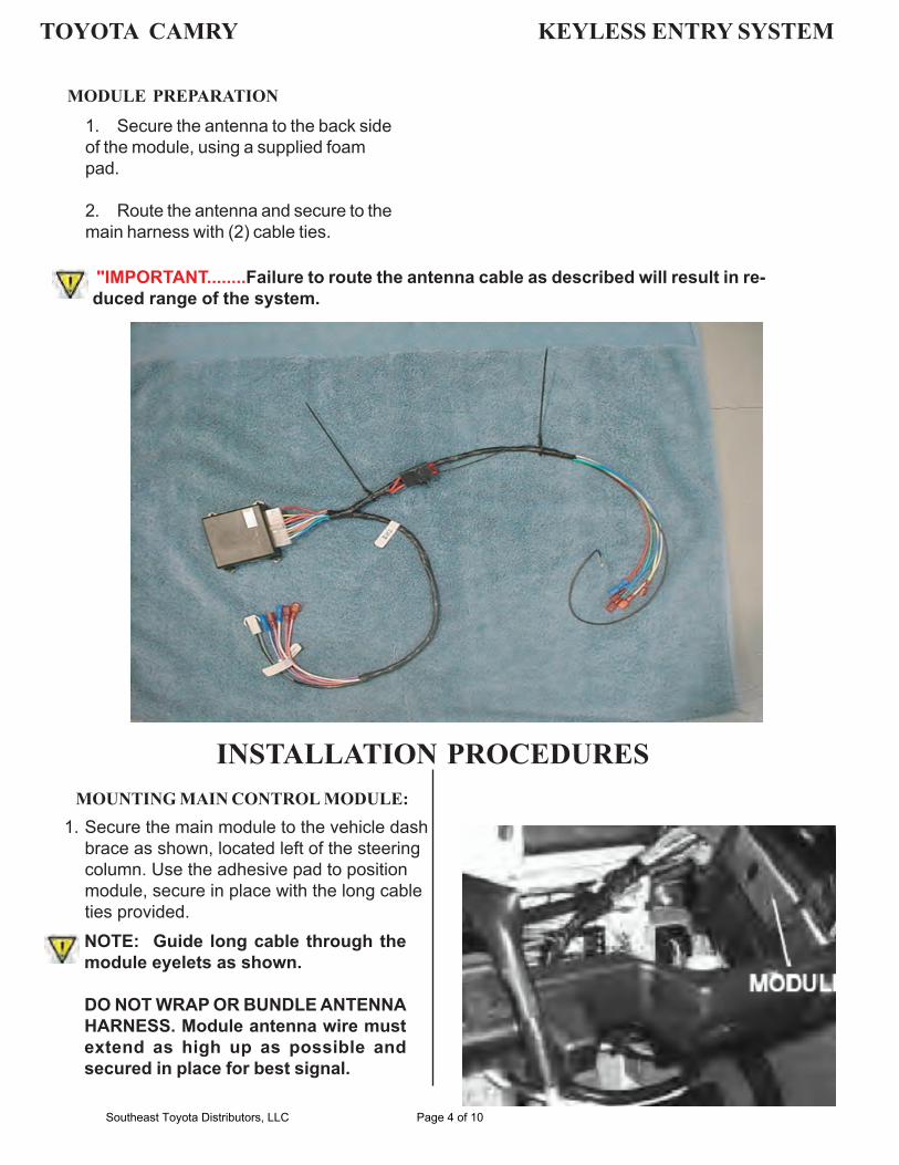
MOUNTING MAIN CONTROL MODULE:
NOTE: Guide long cable through themodule eyelets as shown.
DO NOT WRAP OR BUNDLE ANTENNAHARNESS. Module antenna wire mustextend as high up as possible andsecured in place for best signal.
INSTALLATION PROCEDURES
MODULE PREPARATION
1. Secure the antenna to the back sideof the module, using a supplied foampad.
2. Route the antenna and secure to themain harness with (2) cable ties.
"IMPORTANT........Failure to route the antenna cable as described will result in re-duced range of the system.
TOYOTA CAMRY KEYLESS ENTRY SYSTEM
Southeast Toyota Distributors, LLC Page 4 of 10
Secure the main module to the vehicle dashbrace as shown, located left of the steering column. Use the adhesive pad to position module, secure in place with the long cable ties provided.
1.
IMPORTANT ! After installation, inspect & insure that all Keyless SystemHarness are clear of all HOT, SHARP or MOVING objects
T-TAP INSTALLATION:
A. When installing female T - Tap connectors, be sure the wire is located inside the wire channel of thefemale T - Tap connector before closing connector over the wire with pliers.
Step A Step B Step C
T - Tap Wire from main keylessharness
TOYOTA CAMRY KEYLESS ENTRY SYSTEM
A. Install the ON/OFF bezel and nut. Tightennut with care, do not over torque the nut.
B. Tie wrap to main harness loom in driver'skick panel directly besides the A3 groundlug as shown.
NOTE: Toggle switch must be in the"OFF" position.
MOUNTING THE TOGGLE SWITCH:
INSTALLATION PROCEDURES
Southeast Toyota Distributors, LLC Page 5 of 10
NOTE: Not for installation on vehilce's equipped with factory installed keyless entry.
WIR
ING
DIA
GR
AM
[N
KIP
hctiwS kcoL
y e Kr
genessaP-T
red
a U
se ]:
orec
tnn
co e i
nE
** w
irLUB .TL
e th
t to
ecnnd
cona
apT.3 noitacol ,JI
[N
K/W
HIT
E PI
htci
k Sw
conl
U yK
e re
ngesasP
es U:]
ine ir
w *EN
*G
RE
the
to
on
nect
can
d p
T-Ta
d re a
4.tio
n a
loc
J,
Iec
tor
nnco
ae s
U:]chit
Swt cte
De
ck
lon U
oroD [E
ITH
/WK
INPni e
wir
EUL
B eht ot tcennoc dna pa-TT der
.42 noioc
atl
E2,
I rtocennoc
WH
ITE
roo Dsdra
or -
Tow
tiv
er D
oor U
nloc
k M
or
[D)
elow
Bta
il A
D
e
- (Se
e
ck]
Lo
E/W
HIT
EB
LUar
dswoT -r ot
Mo
r D
oor U
nloc
kve
[ Dri
l A
ita
De
e Se
- (
U]
EC
dyB
oA
ebo
v)
D [
ER
yertt
Ba
D
CV
+12
ue T
-lb
aeU
s ]:
nda pTa
23,
Er o
conn
ect
n i
rew
i
KC
BLA
the
to
t on
nec
cio
n 5.
taclo
[O
W
LLEYy
sor
scc
eD
C A
2V1+p
Ta-T eubl a
Use
]: 3,2E
n co
nnec
tor
iec
t to
the
YELL
OW
wire
n
and
con
. 6
onitcaol
0m
m
1he
t
o tte
rmin
al
g inr
he
tec
t nn
Co
-D
O
UN
GR
C
HA
SSIS
[G
REE
N/R
ED W
IRE
nrH
o re
d T-
Tap
and
conn
ect t
o th
ee
Us
:]ca
tion
8., l
or E
18ec
toW
HIT
E W
IRE
in c
onn
[R
EI
WTEI
WH
sthigLl
aiTe
thto
nnec
t oc
and
pa-TT
red
U
se: ]
ocat
ion
18.
lr E
21,
oB
LAC
K W
IRE
in c
onne
ct
olrnt
Co
elggoT onti gulP- rotc
nenoC xel
Mo
inP 2
.hitc
wS
"A"
LI
DET
A
T
CIR
CU
IK
UN
LOC
S
DO
OR
'
DR
IVER
.5n
2oita
ocIE
2, l
ortce
nnon
ci
RE
IW ET
HI
W het tu
C th
e cu
t wire
,f
rom
bot
h si
des
of
n otiarip
the
insu
ltS
ssehe
key
lt
om
r fE
WH
ITE
WIR
eh tp
mri
cdnap
imrC .ert w
iuc e
th fo deis SSEN
ARH eth
tosesnrah
ssner
key
less
ha
eE
from
thR
E W
IT
LUE/
WH
IB
the
re.
wi
the
cut
id
e of
sC
ON
NEC
TOR
to th
e
Harn
ess
esrW
i
/w
UE
LB
ITE
HW
ripSt
&t C
u Exis
ting
reW
iETI
HW
BLU
E W
IRE
[Hea
dlig
hsth
e R
ED
ct to
ese
red
T-Ta
p an
d co
nnU
]: .71
ion
taoc
or E
21, l
tecn
con
niE
WIR
WIRING DIAGRAM CAMRY
aps
arne
ss le
ngth
, red
T-T
h**
Not
e: D
ue to
IJ
mus
t be
plac
ed 6
"- 8
" fr
om th
e or
.tc
onne
c
Southeast Toyota Distributors, LLC Page 6 of 10
ConflictsConflicts
bolt
on to
p rig
ht o
f cra
sh p
anel
mou
nt.
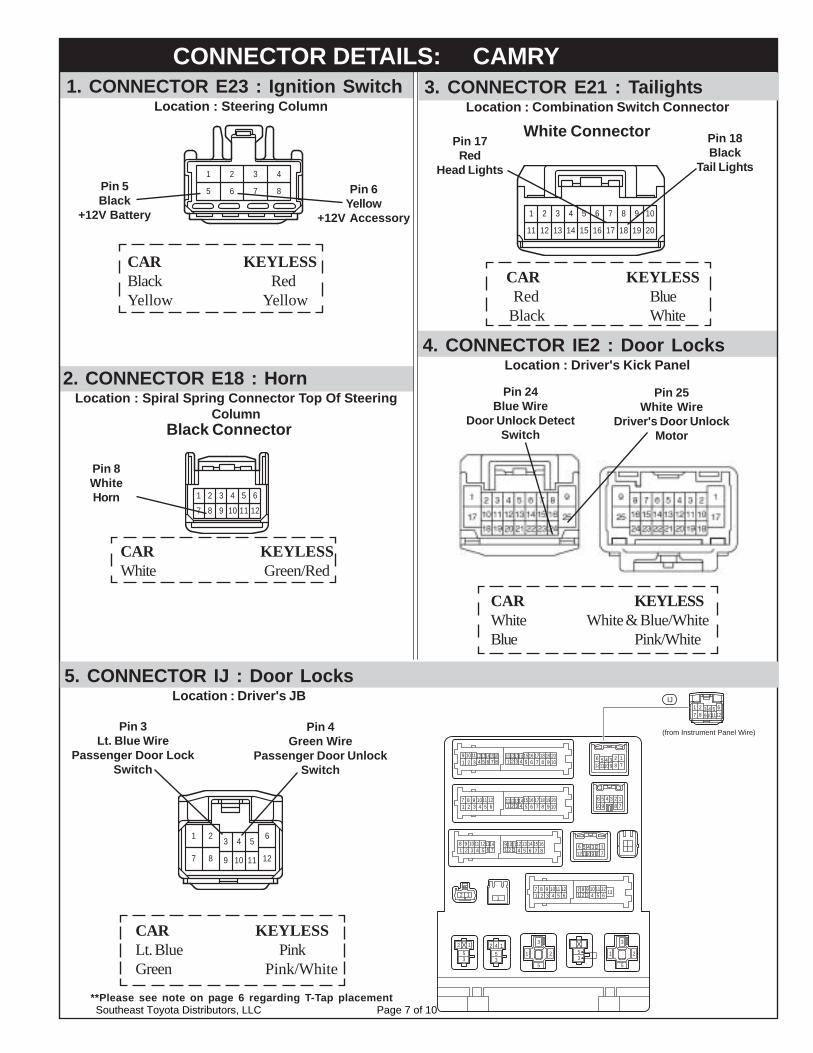
2. CONNECTOR E18 : HornLocation : Spiral Spring Connector Top Of Steering
Column
Pin 8WhiteHorn
3. CONNECTOR E21 : TailightsLocation : Combination Switch Connector
Pin 18Black
Tail Lights
CAR KEYLESS Red Blue Black White
1 2 3 4
5 6 7 8
1. CONNECTOR E23 : Ignition SwitchLocation : Steering Column
1 2 3 4 5 6 7 8 9 10
11 12 13 14 15 16 17 18 19 20
CAR KEYLESSWhite Green/Red
CAR KEYLESSBlack RedYellow Yellow
Pin 5Black
+12V Battery
Pin 6Yellow
+12V Accessory
121097
641 3 5
11
2
8
Black Connector
White ConnectorPin 17Red
Head Lights
4. CONNECTOR IE2 : Door LocksLocation : Driver's Kick Panel
Pin 25White Wire
Driver's Door UnlockMotor
Pin 24Blue Wire
Door Unlock DetectSwitch
CAR KEYLESSWhite White & Blue/WhiteBlue Pink/White
CONNECTOR DETAILS: CAMRY
5. CONNECTOR IJ : Door LocksLocation : Driver's JB
1 2 3 4 5 6
7 8 11 12109
CAR KEYLESSLt. Blue PinkGreen Pink/White
Pin 3Lt. Blue Wire
Passenger Door LockSwitch
Pin 4Green Wire
Passenger Door UnlockSwitch
123456789
123410
10
10
1010
11
1011
1112
12
10 10
10
11 11
11
12
1314 1213141516 15 16 17 18 19 20
(from Instrument Panel Wire)
11
11
12
12
101112
56789
123456789
4 6 7 8 2 9875 6431
101112
12
12
13
13
13
14
141314
15
15
16
16
17 18 19 202 9875 6431
95321
97321
84 5 6
1011 1297321
8
7 8
4 5 6
1
87
64 5
64 5
32
1 32
8321
9
9
94 5 6 7
12 1
1 2 3 4 5 67 8 9
2 153
2 153
2
3
5
1 2
3
5
135
4
IJ
**Please see note on page 6 regarding T-Tap placementSoutheast Toyota Distributors, LLC Page 7 of 10
COMPLETING THE INSTALLATION: CAMRY
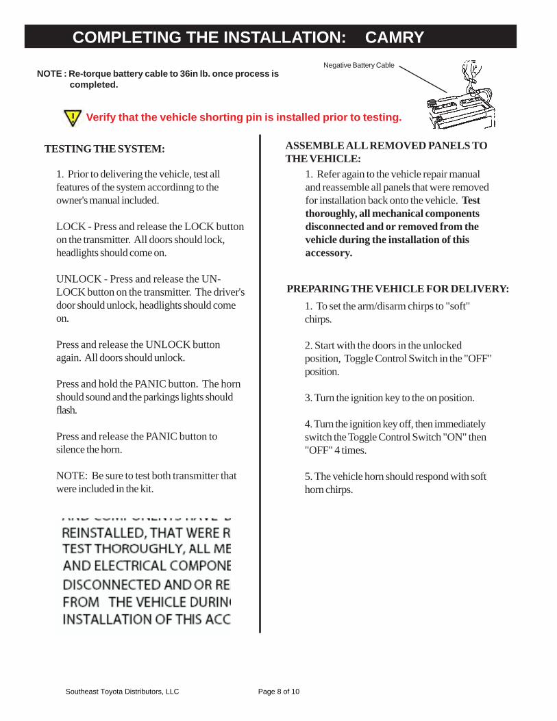
TESTING THE SYSTEM:
1. Prior to delivering the vehicle, test allfeatures of the system accordinng to theowner's manual included.
LOCK - Press and release the LOCK buttonon the transmitter. All doors should lock,headlights should come on.
UNLOCK - Press and release the UN-LOCK button on the transmitter. The driver'sdoor should unlock, headlights should comeon.
Press and release the UNLOCK buttonagain. All doors should unlock.
Press and hold the PANIC button. The hornshould sound and the parkings lights shouldflash.
Press and release the PANIC button tosilence the horn.
NOTE: Be sure to test both transmitter thatwere included in the kit.
ASSEMBLE ALL REMOVED PANELS TOTHE VEHICLE:
1. Refer again to the vehicle repair manualand reassemble all panels that were removedfor installation back onto the vehicle. Testthoroughly, all mechanical componentsdisconnected and or removed from thevehicle during the installation of thisaccessory.
PREPARING THE VEHICLE FOR DELIVERY:1. To set the arm/disarm chirps to "soft"chirps.
2. Start with the doors in the unlockedposition, Toggle Control Switch in the "OFF"position.
3. Turn the ignition key to the on position.
4. Turn the ignition key off, then immediatelyswitch the Toggle Control Switch "ON" then"OFF" 4 times.
5. The vehicle horn should respond with softhorn chirps.
NOTE : Re-torque battery cable to 36in lb. once process iscompleted.
Negative Battery Cable
Verify that the vehicle shorting pin is installed prior to testing.
Southeast Toyota Distributors, LLC Page 8 of 10
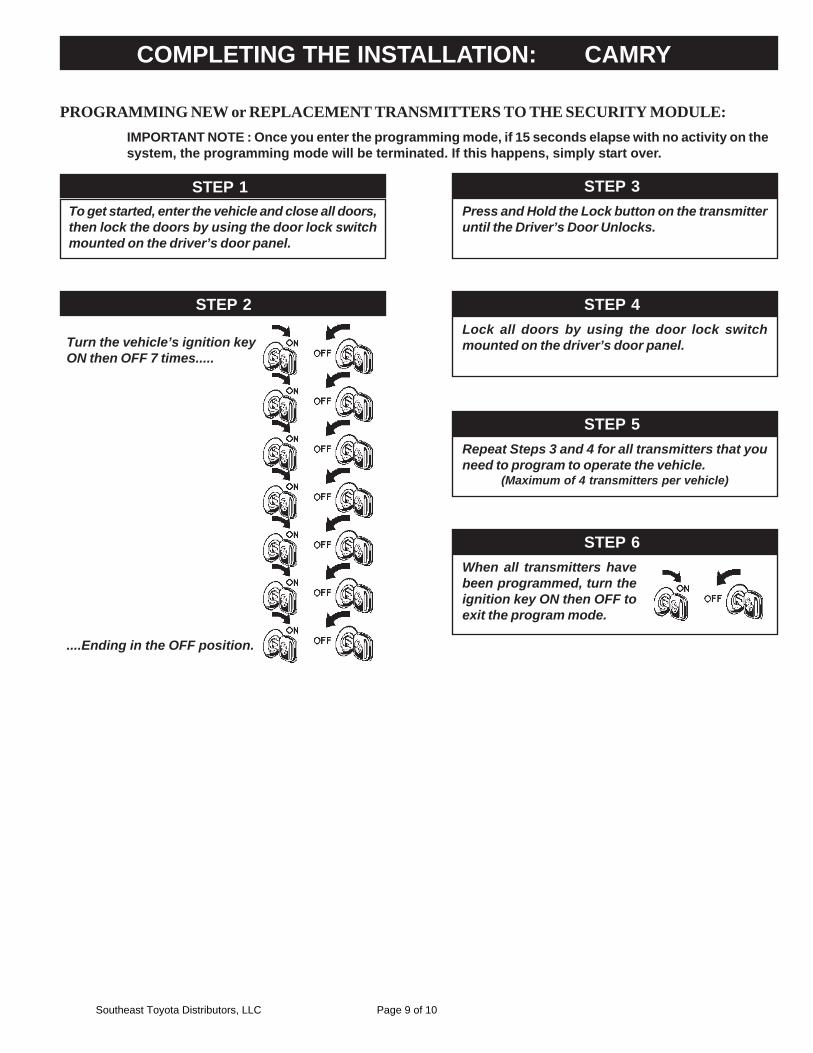
STEP 2
PROGRAMMING NEW or REPLACEMENT TRANSMITTERS TO THE SECURITY MODULE:IMPORTANT NOTE : Once you enter the programming mode, if 15 seconds elapse with no activity on thesystem, the programming mode will be terminated. If this happens, simply start over.
STEP 1
Turn the vehicle’s ignition keyON then OFF 7 times.....
....Ending in the OFF position.
To get started, enter the vehicle and close all doors,then lock the doors by using the door lock switchmounted on the driver’s door panel.
STEP 3Press and Hold the Lock button on the transmitteruntil the Driver’s Door Unlocks.
STEP 4Lock all doors by using the door lock switchmounted on the driver’s door panel.
STEP 5Repeat Steps 3 and 4 for all transmitters that youneed to program to operate the vehicle.
(Maximum of 4 transmitters per vehicle)
STEP 6When all transmitters havebeen programmed, turn theignition key ON then OFF toexit the program mode.
COMPLETING THE INSTALLATION: CAMRY
Southeast Toyota Distributors, LLC Page 9 of 10
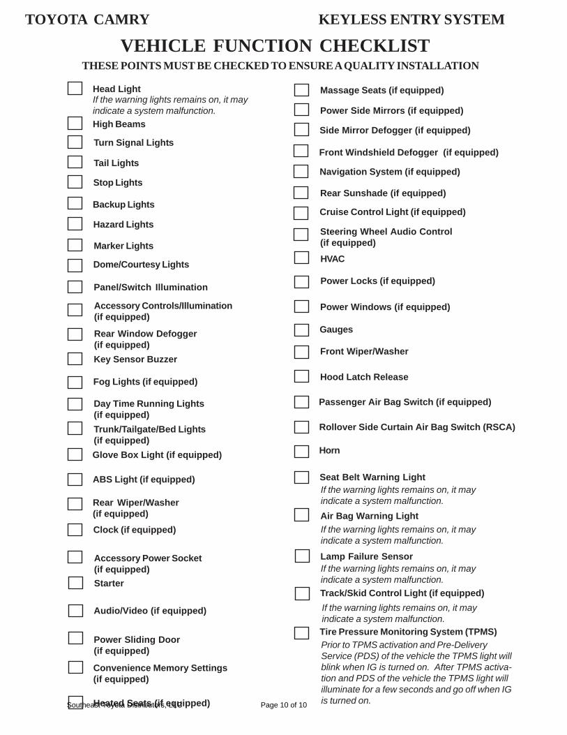
VEHICLE FUNCTION CHECKLISTTHESE POINTS MUST BE CHECKED TO ENSURE A QUALITY INSTALLATION
Head Light
High Beams
Turn Signal Lights
Tail Lights
Stop Lights
Backup Lights
Hazard Lights
Marker Lights
Dome/Courtesy Lights
Panel/Switch Illumination
Accessory Controls/Illumination(if equipped)
Rear Window Defogger(if equipped)Key Sensor Buzzer
Fog Lights (if equipped)
Day Time Running Lights(if equipped)Trunk/Tailgate/Bed Lights(if equipped)Glove Box Light (if equipped)
ABS Light (if equipped)
Rear Wiper/Washer(if equipped)Clock (if equipped)
Accessory Power Socket(if equipped)Starter
Audio/Video (if equipped)
Power Sliding Door(if equipped)
If the warning lights remains on, it mayindicate a system malfunction.
Convenience Memory Settings(if equipped)
Heated Seats (if equipped)
Massage Seats (if equipped)
Power Side Mirrors (if equipped)
Side Mirror Defogger (if equipped)
Front Windshield Defogger (if equipped)
Navigation System (if equipped)
Rear Sunshade (if equipped)
Cruise Control Light (if equipped)
Steering Wheel Audio Control(if equipped)
HVAC
Power Locks (if equipped)
Power Windows (if equipped)
Gauges
Front Wiper/Washer
Hood Latch Release
Passenger Air Bag Switch (if equipped)
Rollover Side Curtain Air Bag Switch (RSCA)
Horn
Seat Belt Warning Light
Air Bag Warning Light
Lamp Failure Sensor
Track/Skid Control Light (if equipped)
If the warning lights remains on, it mayindicate a system malfunction.
If the warning lights remains on, it mayindicate a system malfunction.
If the warning lights remains on, it mayindicate a system malfunction.
If the warning lights remains on, it mayindicate a system malfunction.
TOYOTA CAMRY KEYLESS ENTRY SYSTEM
Tire Pressure Monitoring System (TPMS)Prior to TPMS activation and Pre-DeliveryService (PDS) of the vehicle the TPMS light willblink when IG is turned on. After TPMS activa-tion and PDS of the vehicle the TPMS light willilluminate for a few seconds and go off when IGis turned on.
Southeast Toyota Distributors, LLC Page 10 of 10


![OME-PIO-DA Sofware manualOME-PIO-DA Software Manual [Win 95/98/NT/2000] 1. Introduction The software is a collection of digital I/O subroutines for the OME-PIO-DIO series add-on cards](https://img.pdfslide.net/doc/110x75/6138f1aba4cdb41a985b628f/ome-pio-da-sofware-manual-ome-pio-da-software-manual-win-9598nt2000-1-introduction.jpg)