Embed Size (px)
Citation preview

JOHNS HOPKINS APL TECHNICAL DIGEST, VOLUME 30, NUMBER 4 (2012) 321
beam at a receiver or to point the receiver field of view (FOV) at the transmitter. Transmitter and receiver aper-tures can be colocated or separate, sometimes protrude from the vehicle body, and often require very precise pointing and tracking to maintain a link.1 Because of eye-safety requirements and typical link margins (received
INTRODUCTIONFree-space optical communications (FSOC) is a prom-
ising technology for high-bandwidth data links where a cable (fiber or wire) is not feasible or where RF commu-nication is inadequate (e.g., because of data rates, spec-trum allocation, security, or jamming). FSOC terminals typically use mechanical gimbals to point a transmitted
Conformal Free-Space Optical Communications Terminal Designs for Highly Confined Vehicles
Daniel V. Hahn, David M. Brown, Andrea M. Brown, Chun-Huei Bair, Mark J. Mayr, Nathan W. Rolander, Joseph E. Sluz, and Radha Venkat
e propose novel designs for free-space optical com-munications transmitter and receiver terminals. The
designs emphasize reduction or elimination of large, gimbal-based protrusions, include a minimal number of components at the surface, use fiber optics to keep supporting components remote from the surface, and minimize moving parts. The transmit terminal is composed of a fiber switch, fiber bundle, and surface lens. Switching the communications signal among individual fibers in a bundle coarsely steers the beam with a moderate divergence over a large field of regard via lens refraction. The receive terminal uses a microlens to couple the incident optical signal into an individual fiber in another bundle routed to remote optical detectors. Each fiber in the bundle collects power from a distinct solid angle of space; the use of multiple fibers enlarges the total field of view of the receiver. The microlens-to-fiber-bundle design is scalable and modular and can be replicated in an array to increase aperture size. The microlens (array) is moved laterally with a piezoelectric transducer to optimize coupling into a given fiber core in the bundle as the source appears to move because of relative motion between the transmitter and receiver.

D. V. HAHN ET AL.
JOHNS HOPKINS APL TECHNICAL DIGEST, VOLUME 30, NUMBER 4 (2012)322
made to prioritize these aspects over traditional primary design goals, such as link efficiency, of FSOC systems. Typical FSOC systems use collimated beams and designs that minimize the beam size at the receiver terminal to achieve maximum efficiency between transmitted and received optical power. The terminal designs presented herein are not intended to compete with existing FSOC terminal designs but rather are focused on providing options for applications whose requirements preclude the use of more traditional designs.
TRANSMITTER TERMINALThe transmitter terminal design is depicted in Fig. 1
and centers about a fiber bundle routing the optical signal (present in any one of the fibers in the bundle) to a surface-mounted lens or lens system. Each fiber in the bundle is aligned with a different cross section of the terminal lens; light exiting any given fiber will conse-quently be refracted and directed toward some unique solid angle of the FOR of the transmitter aperture. Note that the intent is to direct a communications beam having a moderate divergence. The optomechanical design overlaps the divergence of each fiber such that there are no holes in the greater FOR (transmitter cone) of the system. By optically switching among the fibers in the bundle, it is possible to coarsely steer the communi-cations beam over the FOR to maintain a link with the receiver at all times. The system is designed to briefly suspend transmission during switching operations,
power is proportional to the area of the receiver aper-ture), these terminals can have aperture diameters on the order of 1–40 cm, with a suitably sized mechanical gimbal system. The large desired field of regard (FOR) of gimbal-based systems is often achieved via the angular mechanical range of motion of the system.
This approach is impractical for many applications, such as those that require small size and weight and minimal disruption to a vehicle shape or skin. Exam-ples of such applications include an unmanned airborne vehicle (UAV) communications network, a clandestine terrain-based telemetry link, a missile telemetry down-link to a UAV, a small UAV downlink to a ground sta-tion, or a data relay system between separated launch vehicle (rocket) sections. In many cases, inherent vehi-cle motion and harsh shock and vibration environments can put significant demands on the design of a pointing/tracking mechanical gimbal system. We propose novel and general designs for FSOC transmitter and receiver terminals that focus on achieving wide transmitter FOR and wide receiver FOV while eliminating the need for large, gimbal-based structures or protrusions. Other key design aspects include requiring a minimal number of components at the vehicle surface, using fiber-optic technology to keep most supporting electrical and opti-cal components remote from the vehicle surface, and minimizing moving parts. Separate terminal designs are considered for transmit and receive functions.
In focusing the designs on size, weight, and flex-ible component location, an inherent trade has been
Figure 1. Conceptual transmitter terminal design consisting of a fiber bundle terminated with a surface-mounted lens. Each fiber in the bundle is aligned with a different cross section of the lens and directs light toward some unique solid angle (divergence) of the FOR with a finite, noncollimated divergence and designed overlap. Optical switching allows for coarse beam steering.
CONFORMAL FREE-SPACE OPTICAL COMMUNICATIONS TERMINAL DESIGNS
JOHNS HOPKINS APL TECHNICAL DIGEST, VOLUME 30, NUMBER 4 (2012) 323
As previously stated, one of the terminal design goals is to use fiber-optic technology to keep most support-ing electrical and optical components remote from the transmitter aperture surface. This goal is realized by using a fiber bundle to transfer the communications beam to the surface lens (conformal with the surface of the vehicle or terminating with a conformal window). On the source side of the bundle, however, an additional component is needed (in comparison to gimbal-based transceiver terminals)—a fiber switch to select the appropriate transmission fiber.
The photonics industry has engineered many dif-ferent types of fiber switches for many applications. Technologies include, but are not limited to, micro-electromechanical systems (MEMS) devices, free-space reflective or refractive systems (coupling out of and into fiber), mechanical latching systems, birefringent photonic waveguides, acousto-optical materials, and electro-optical materials. Most commercial switches use SM fiber, although custom components can be manu-factured using MM fiber. Alternatively, SM fiber is often spliced to MM fiber (with negligible loss),5 allowing the output fiber from a SM switch to be spliced to a MM input bundle fiber. Some of the more promising tech-nologies for this terminal design are mechanical latch-ing switches and electro-optical material switches. An example of the latter is the 1 35 Electro-Optic Fiber Switch developed by AdvR Inc. for a NASA fiber lidar system.6, 7 The technology is based on a 2-D arrangement of AdvR’s electro-optic beam deflectors and is capable of higher-power switching (>1-W continuous wave) than typical MEMS and waveguide systems are capable of.7 An image of the switch and a pictorial depiction of its operating principles are shown in Fig. 3.6 The ability of this switch to handle high power is advantageous for this transmitter terminal design, where the transmitted power will be spread out over the divergence.
Behind the switch, the source optics and electronics are similar to typical gimbal-based FSOC systems, being composed of a laser source, modulator, and amplifier. However, the aforementioned relaxation of eye-safety requirements opens up the potential wavelength range to an increased solution space that is useful when available electrical battery power is limited. Therefore, although many FSOC systems choose to operate at or near the 1550-nm wavelength (where light does not pass through the cornea and focus on the retina), we have greater flex-ibility. In contrast, constraints in size, weight, and robust-ness narrow the solution space down to fiber laser and laser diode technologies as opposed to free-space cavity lasers, such as the HeNe or Nd:YAG lasers. The net gain is therefore the option of using laser diodes or fiber lasers below and outside of the typical 1550-nm FSOC regime.
Laser diodes are by far the most efficient source, with electrical-to-optical conversion efficiencies in excess of 60% (current and ongoing research are pushing these
which are on the timescale of milliseconds per switch; the frequency of switching depends upon the specific link scenario (but is assumed to be at frequencies much lower than the ~1 kHz for switching operations). The outage time resulting from data source switching is on the order of typical fade times of FSOC links and can therefore be considered an additional fade event that occurs infrequently relative to the channel fade events. Network-level protocols are commonly used to ensure reliable data delivery in the presence of these fades.2
In overlapping the divergence of each fiber, it is important to consider the intensity profile of the com-munications beam. For example, single-mode (SM) fiber yields a far-field intensity pattern of a Gaussian nature. In contrast, the superposition of modes within a multi-mode (MM) fiber itself creates a more square (top-hat) pattern, often referred to as being super-Gaussian, with near-uniform intensity over some solid angle; this is shown in Fig. 2.3, 4 Regardless of the choice of fiber, the projected power per unit area at the receiver must be high enough to close a link at all angles throughout the FOR, including those regions of overlap where the intensity field from the transmitter may be diminished.
While constraints on pointing accuracy are relaxed because of the moderate transmitter divergence, con-straints on transmitter power are consequently increased to maintain adequate irradiance at the receiver aperture. Such a system is typically not eye safe at the transmitter aperture. However, as the beam spreads over the diver-gence, eye-safe power levels will be attained well ahead of the receiver aperture (whether by design or not). Cer-tain applications may not even require eye safety at the transmitter aperture, such as those where human observ-ers are not close and where size, weight, and mounting limitations are especially constraining.
Inte
nsity
0–1 0
Lateral dimension
SM profileMM profile
1
Figure 2. Overlap of far-field intensity patterns from SM and MM fiber. The super-Gaussian nature of the MM fiber lends itself well to overlapping beams with nearly uniform power levels.

D. V. HAHN ET AL.
JOHNS HOPKINS APL TECHNICAL DIGEST, VOLUME 30, NUMBER 4 (2012)324
fiber laser and silicon avalanche photodiode (APD) technologies progress, fiber lasers and amplifi-ers will probably be developed for the 1030-nm regime,14, 15 which is much closer to the peak Si quan-tum efficiency (typically in the 900- to 950-nm range, depending on the specific doping level).
The typical FSOC wavelength range of 1530–1565 nm also offers comparable generation efficiencies (and, as previously stated, greater eye safety)13 but requires indium gallium arsenide (InGaAs) detec-tors, which have large bandwidths but also have higher noise charac-
teristics than Si detectors. The intrinsic gain when oper-ating in linear APD mode is also lower in InGaAs than Si because the InGaAs material cannot be operated with as large of an electrical gain.13 In addition, InGaAs detectors require cooling to reach optimal efficiencies (in contrast to Si detectors, which can operate efficiently at room temperature or elevated temperatures).
Ultimately, the choice of laser source depends on the application requirements, including eye safety, power limitations, transmitter and receiver platforms, and so on. For some applications, wavelength trade studies favor the 1030- to 1060-nm regime, where ytterbium-doped fiber transmitters are used in conjunction with Si APDs. This is in contrast to the majority of FSOC solutions that operate in the 1550-nm region using InGaAs detection technology (and compatible standard SM fiber technolo-gies). Future applications might be best served with all semiconductor-based master-oscillator-power-amplifier transmitters and vertical-cavity surface-emitting laser (VCSEL) diode technology, provided these technologies show increased bandwidths at high powers as they mature.
efficiencies further to near 80% in a laboratory set-ting).8 However, laser diodes have two main drawbacks. First, the output laser beam has a poor beam profile; as a result, laser diodes require coupling (with loss) to optical fibers or other beam homogenizing approaches to achieve a reasonable profile. Second, the modulation speed of laser diodes operating at relatively high powers (on the order of 100 mW) is limited to rates well below the gigahertz regime, which may or may not be accept-able for a given application. The most common design architecture of a high-power and high-bandwidth opti-cal transmitter is a master-oscillator-power-amplifier arrangement. The master oscillator involves typically a very-low-power distributed feedback diode laser, which can either be directly modulated up to ~2.5 GHz or externally modulated with a Mach–Zehnder interfer-ometer electro-optical modulator to modulation band-widths in excess of 40 GHz. High-power laser diodes are often used as pump sources for a high-power amplifier, where the latter typically consists of an erbium-doped fiber (1550 nm) or a ytterbium-doped fiber (1030–1100 nm). Because of the possible improvement in system efficiency and overall simplicity, the architecture of high-speed laser diodes followed in an integrated chip by a high-power diode amplifier is an active field of cur-rent research and development.9 If and when this effort bears fruit, high-power laser diode transmitters will become an attractive option for some FSOC systems.
For applications requiring bandwidths in the giga-hertz regime, fiber-based transmitters offer more modest electrical-to-optical conversion efficiencies on the order of 30–40%10 but allow for modulation rates in excess of 1 GHz.11, 12 Fiber-based transmitters can also be ampli-fied to achieve powers in the kilowatt range (not that these powers would be needed or desired for FSOC), with the most efficient wavebands in the 1050- to 1100-nm range.13 Unfortunately, these wavelengths are very near the band edge of silicon (Si), so the detection effi-ciency for a Si detector is not optimal. However, as both
Figure 3. AdvR 1 35 Electro-Optic Fiber Switch: up to 2 W of power, switch rate of 150 µs, 5.5 1.5 1.5 in. (Reproduced with permission from Ref. 6.)
100
80
60
40
20
0
5.04.54.03.53.02.52.01.51.00.5
00 MaxTransmitter peak power (arbitrary units)
Tran
smitt
er d
iver
genc
e (d
egre
es)
Num
ber o
f bun
dle
fiber
s
Figure 4. Transmitter terminal trade space between power, beam divergence, and number of fibers (switches).

CONFORMAL FREE-SPACE OPTICAL COMMUNICATIONS TERMINAL DESIGNS
JOHNS HOPKINS APL TECHNICAL DIGEST, VOLUME 30, NUMBER 4 (2012) 325
A microlens array (individual lens diameter <1 cm) is used to enlarge the receiver aperture area while maintaining minimal focal point movement such that the effective aperture area is comparable to that of the traditional gimbal-based design. A fiber bundle in an optimal hexagonal packing pattern17 is placed (at the lens focal distance) behind each lens in the array. Large-core and small cladding MM fibers are used to populate the bundles so as to minimize distance between fiber cores, thereby minimizing “dead” areas of light coupling. Spaunhorst et al.18 have proposed a similar approach albeit with the limitation that good coupling efficiency into one of the fibers in the bundle (for each lens) is only achieved at discrete angles.18 Such a design is not tactically viable without a means to ensure that incident light is always coupled into one of the bundle fibers for each lens. This can be accomplished by introducing a piezoelectric transducer (PZT) to translate the lens array (or fiber bundle array) as a whole. Although this solu-tion does introduce mechanical motion, the motion is small, robust, and reliable and requires minimal power.19 In addition to being well suited for use on platforms that could encounter harsh motion environments, PZTs also offer operational bandwidths (>1 kHz) that are much greater than those typically required to maintain cou-pling of light into a fiber undergoing mechanical plat-form jitter (~100 Hz).19
Having selected PZTs to control and adjust the posi-tion of the fiber bundle array with respect to that of
Having discussed both fiber switching and laser sources, it should be noted that the main design tradeoffs for the trans-mitter being discussed are size, weight, and power when con-sidering the power draw and number of switches. When developing the link model for a diverging beam, high laser power has the benefit of allow-ing for larger divergences and fewer bundle fibers (switches). Such a design will minimize switch size but require more power for laser source ampli-fication and possibly cooling. Alternatively, a large number of switches will minimize bat-tery draw but result in signifi-cant space requirements and possibly more switching events in the communications time-line. This is illustrated in an example trade study between laser power, beam divergence, and number of switches in Fig. 4. As can be seen in this figure, the two curves sug-gest that an optimal solution space exists when consider-ing constraints of size, weight, power, and cost.
RECEIVER TERMINALWhen considering an FSOC system, it is highly
desirable to maximize both transmitter laser power and receiver aperture area in order to maximize the link margin. However, for the applications under consider-ation, a large gimbal-based receiver is just as undesirable as a like transmitter for the same reasons as discussed earlier. Additionally, the receiver must either be able to point at the transmitter or have a wide enough FOV that the communications beam couples through the receiver optics to the detector(s). A natural solution exists given these two constraints—use a small receiver aperture and thereby minimize focal point movement behind the aperture, which also increases the FOV. This realiza-tion leads to potentially high power requirements on the transmitter; however, it is possible to increase the effec-tive receiver aperture area via an array of small aper-tures. Combining these ideas with the terminal design goals (requiring a minimal number of components at the surface, using fiber-optic technology to keep most supporting electrical and optical components remote from the surface, and minimizing moving parts) leads to the proposed receiver terminal design, which is shown in Fig. 5.16
Figure 5. Conceptual design of lens array/fiber bundle wide FOV FSOC receiver. A PSD controls the position of a microlens array such that an incident communications beam is always coupled into one fiber of a bundle behind each microlens in the array. Light coupled into like-positioned fibers in each array cell is optically combined and routed to a remote set of detectors. (Repro-duced with permission from Ref. 16, © 2010, The Optical Society—OSA.)
D. V. HAHN ET AL.
JOHNS HOPKINS APL TECHNICAL DIGEST, VOLUME 30, NUMBER 4 (2012)326
respect to the lens) to optimize the SNR of the signal, i.e., both maxi-mizing received signal and mini-mizing solar radiation coupling into the signal fiber. This concept illustrates one of the benefits of using a fiber bundle behind each lens—the background noise pres-ent on the signal detector comes from only that portion of the FOV that couples into the signal fibers. The design enables the receiver to have a wide effective FOV while at the same time selecting a narrower FOV for reception of the commu-nications beam, thereby mini-mizing the effect of background radiation. In the same way that the transmitter FOR was divided into the divergences from each bundle fiber, so too is the receiver FOV composed of the instanta-
neous FOVs (iFOVs) of each bundle fiber; the difference is that in the receiver design, gaps between the iFOVs are eliminated via PZT motion.
To maintain a link with the receiver as described above, a feedback loop is needed to control lens-to-fiber-bundle positioning via PZT motion. The simplest implementation of this feedback loop is to introduce a position-sensing detector (PSD) or equivalent behind one of the many lenses in the array. As an alternative, the PSD could be matched to an alternate lens of dif-ferent specification and calibrated. The measured signal position on the PSD directly relates to the incident angle of the communications signal beam and can be compared with a priori knowledge of fiber core locations (note that if multiple lens arrays are positioned on non-coplanar receiver vehicle surfaces, one PSD is needed for each surface). A simple control loop would then be used to optimize the optical coupling into the nearest fiber core or to maximize the SNR of the communications signal, as previously discussed and illustrated in Fig. 6. A more advanced control loop could use deliberate hyster-esis and a low-pass filter of the electrical signal to reduce jitter between two cores.
A key aspect of this design is that the fiber bundle positioning behind each lens of the array be consistent and that light coupled into like-positioned fibers be optically combined prior to conversion to an electrical signal, as illustrated in Fig. 5. Light from the center fibers of each bundle are combined, and light from the upper-left fibers of each bundle are combined; however, no light from upper-left fibers are ever combined with that from center fibers. Such precise fiber positioning can be achieved via a fixture plate fabricated with a precision-machining method such as electrical discharge machin-
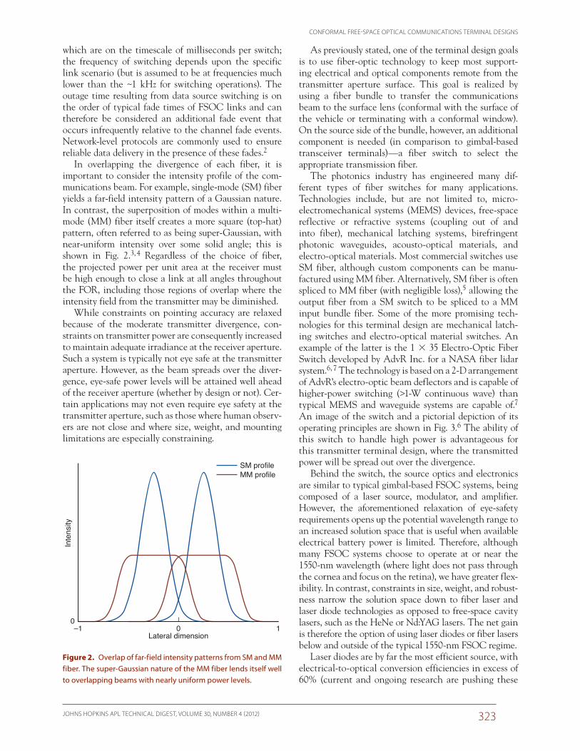
the lens array, we introduce a constraint on fiber size and, consequently, lens size. Because the motion range of PZTs is on the order of 100 mm, the fiber cladding size must be such that intercore distances are well within this range of motion.19 With this in mind, it is impor-tant to point out the motivation behind and benefit of using a fiber bundle as opposed to a single, very-large-core fiber. A single, large-core fiber would have the associated consequence that the overall system FOV of the receiver would be determined by the lens and fiber core dimensions, calculable via the thin lens equation.20 This FOV would have to be large enough such that the transmitter was always contained within it. In so doing, a large amount of background radiation would couple into the fiber along with the communications signal, thereby adversely affecting the signal-to-noise ratio (SNR). The results could be catastrophic to the com-munications system if too much background radiation were present. By introducing a fiber bundle, it is possible to couple only a fraction of the background radiation within the overall FOV into the signal fiber (each fiber in the bundle is routed to a distinct detector), thereby significantly increasing the SNR. This concept is illus-trated in Fig. 6, which shows the focal plane behind a lens with seven fibers in a bundle. In this example, the communications beam (transmitter) is close to the sun (in angle space), and both are within the overall FOV of the receiver. In the left panel of Fig. 6, the receiver is aligned for maximum coupling of the communications signal into the upper-left fiber, with a small amount of the total solar noise also coupling into this fiber (note that solar noise is only one example of a potential back-ground noise source). In the right panel, the receiver is aligned (via PZT adjustment of the fiber bundle with
Communications beam Communications beam
FOV (seven-�ber hexagon), ~10° in prototype(adding more �bers will further increase FOV)
SunSun
FOV(single �ber)
Figure 6. Focal plane of one microlens array (on fiber plate surface), including seven large-core, small cladding fibers, the communications beam (red dot), and the Sun (yellow circle). In the left panel, signal strength alone is maximized. In the right panel, the SNR is maxi-mized. In each case, solar background is significantly reduced in the communications fiber (upper left) than would be the case if a single, larger core fiber with the same overall FOV were used in the receiver design.

CONFORMAL FREE-SPACE OPTICAL COMMUNICATIONS TERMINAL DESIGNS
JOHNS HOPKINS APL TECHNICAL DIGEST, VOLUME 30, NUMBER 4 (2012) 327
EXPERIMENTAL VALIDATIONProof-of-concept experiments were conducted using
prototypes of the transmitter and receiver terminals assembled in a laboratory configuration. All optical components were of appropriate scale for small plat-forms; however, no miniaturization of supporting com-ponents (electronics, PZT stage, etc.) was undertaken. For example, the receiver terminal was constructed using a microlens array of 2-mm-diameter lenses coupling to fiber bundles of 220/240-mm core/cladding fibers. Con-trarily, the PZT stack was a commercial system measur-ing 2.5 in. across in each dimension.
One experiment tested the ability of the receiver to track the transmitter under varying orientation (point-ing) between the two. Figure 8a shows a diagram of the experimental configuration; Fig. 8b shows a picture of the receiver front end. The receiver assembly was mounted on two rotary stages in a tip/tilt configuration with the receiver optics positioned at the center of rota-tion of each stage. This configuration enabled control of the orientation of the receiver with respect to incoming light from the transmitter, which overfilled the receiver aperture. Moving either of the rotation stages caused the transmitted light to hit the lens array and PSD lens at a different angle, thereby focusing it to a different loca-tion at the respective focal planes. The position of the focused spot on the PSD was used to determine the dis-tance to move the PZT (lens array) to couple into the closest bundle fiber (behind each lens) in the focal plane of the fiber plate.
Figure 9a illustrates the focal plane of an individual bundle in the fiber plate. The corresponding FOVs of the receiver without and with PZT motion (of the lens array) are mapped in Figs. 9b and 9c, respectively, where the color map represents APD current as derived from optical power reaching each of the seven APDs. As can be seen from the data, the system FOV is greater than 20° along each primary axis. Also evident in Fig. 9b are numerous null spaces of angular coupling due to physical dead space in between fiber cores. Figure 9c
ing. The design of such a fiber plate is shown in Fig. 7 alongside a photograph of a prototype plate fabricated at APL. In this plate design, hexagonal holes with corner radii matched to the radius of a single fiber are used to tightly hold the hexagonally packed bundles of fibers. For a given fiber bundle, each fiber is routed to a different detector; the total number of detectors in the system is equal to the number of fibers in each bundle. By using this approach, signals can be optically com-bined from receiver microlenses at distributed mount-ing locations (e.g., different locations on the vehicle for aperture diversity or to accommodate mounting limitations) without introducing additional detectors or complexity.
Just as the transmitter terminal design required the additional fiber switch component, the receiver design requires additional components to optically combine light, thereby building up an effectively larger aperture than that of a single microlens. Unfortunately, the com-bining of optical communications signals in a large-core fiber is far from common practice. However, potential components have been developed for other applications. The most suitable technology is the MM fiber combiner, such as those manufactured by Neptec21 for purposes of fiber laser pump combiners. These combiners can be made with a variety of input and output fiber sizes (input fibers typically have a 100- or 200-mm core, and output fibers typically have a 200- or 400-mm core) in configu-rations of up to 19 input fibers to 1 output fiber, and the combiners could potentially be stacked for multiple stages of combination. Another potential component for use in optical signal combination is the compound para-bolic concentrator (CPC). Because of the large numeri-cal aperture at the output of CPCs, they are practical only as the final stage of optical combining and would have to be coupled directly to the detectors.22, 23 CPCs could be used as a final stage of combination after ini-tial stages of MM fiber combiners; this would also aid in coupling efficiency because MM combiners increase the numerical aperture from the input to the output fibers (CPCs can accept a larger input numerical aperture than current MM combiners). LoPresti et al.24 have also identified optical signal combining as a key design aspect and are investigating alternate methods, including free-space methods.24 The use of fiber combiners also enables multiple collection apertures on a vehicle, including on conformal surfaces, while routing collected photons to a single set of remote internal instrumentation.
Figure 7. Fiber plate mechanical design and photograph of prototype plate populated with large-core fibers and bonded with UV-cured epoxy.

D. V. HAHN ET AL.
JOHNS HOPKINS APL TECHNICAL DIGEST, VOLUME 30, NUMBER 4 (2012)328
shows that these nulls were effec-tively removed by introducing PZT motion to the microlens array. This is a critical point because it is the sole reason for introducing transla-tional motion to the lens array—without it, a communications link would be impossible to attain at certain discrete angles within the receiver FOV.
A test sequence of rotary stage motion that crossed many of the nulls was used in an automated experiment; this sequence is illus-trated by the black arrows in Figs. 9b and 9c. The APD response (the digital representation of the APD current) was monitored and recorded as the motorized rotary stages moved through the test sequence at 0.5° per second for the cases of stationary and translating lens arrays. Figure 10 shows the resulting APD responses of the two scans overlaid; the black line shows the test sequence with a stationary lens array, and the red line shows the same test sequence but with a translating lens array. Numerous dropouts of extended duration were observed when PZT motion was dis-abled; these dropouts represent the natural nulls in angular coupling. These nulls were eliminated using PZT motion—the time-widths of the dropouts were reduced to the time it took the receiver to switch channels (fibers). Therefore, if the angular relation between transmit-
140010
5
0
–5
–10
1050
700
350
00 5–5 10100
(a) (b) (c)
5–5–10 –10
Vert
ical
rota
tion
(deg
rees
)
Horizontal rotation (degrees)
C
D
F A
G B
E
Figure 9. (a) Fiber placement within a hexagonal hole. (b) The FOV of the receiver with a stationary lens array. (c) The FOV with lens array translation. The color map represents APD current as derived from optical power reaching each of the seven APDs.
Figure 8. (a) Experimental setup constructed to test transmitter and receiver designs. The orientation of the receiver with respect to the transmitter was controlled by two rotary stages in a tip/tilt configuration with the receiver optics positioned at the center of rota-tion of each stage. (b) Picture of the receiver optical front end.

CONFORMAL FREE-SPACE OPTICAL COMMUNICATIONS TERMINAL DESIGNS
JOHNS HOPKINS APL TECHNICAL DIGEST, VOLUME 30, NUMBER 4 (2012) 329
ter and receiver were to remain stationary in a natural angular null of the receiver, a data link would still be possible because of the translational motion capability between the lens array and fiber plate.
CONCLUSIONNovel designs for FSOC transmitter and receiver ter-
minals were presented; the focus of these designs is to achieve wide FORs and FOVs while eliminating the need for large, gimbal-based structures or protrusions. Other key design goals include requiring a minimal number of components at the vehicle surface, using fiber-optic technology to keep most supporting electrical and opti-cal components remote from the vehicle surface, and minimizing moving parts. Separate terminal designs were considered for transmit and receive functions.
The transmitter design uses an optical fiber switch and fiber bundle to route the communications signal to a surface lens. The optical signal will be refracted to some fractional divergence of the overall FOR of the transmitter depending on which portion of the surface lens it intersects. The divergence of each bundle fiber is designed to be moderate and to overlap with the diver-gences of adjacent fibers. In this way, coarse beam steer-ing is attained.
The receiver design uses closely packed, large-core fibers in a hexagonal pattern behind each microlens in an array to create an effective large-aperture detector that is segmented into several channels (fibers). Fur-thermore, the locations of micro-lens arrays can be distributed to achieve aperture diversity (to average across spatial variations in received power) or to accom-modate mounting limitations. By sending the separate opti-cal channels to independent detectors, one may think of this technological approach as a fiber-optic-based detector array. Fea-sibility of the proposed receiver design was evaluated through both simulation and experiment; this was discussed in detail in a previous paper.16 A proof-of-concept experiment highlight-ing the FOV of the receiver and the receiver’s ability to track the transmitter under varying angu-lar orientation was presented.
ACKNOWLEDGEMENTS: We thank the many people at APL who have contributed to the continuing success of this project. We specifically thank Kevin Baldwin, Michael Dennis, Juan Juarez, Matiwos Kafel, John Lehtonen, John Orndorff, James Riggins, Kurt Ruckelshaus, Raymond Sova, William Torruellas, and David Young for their support.
REFERENCES 1Chen, C. C., and Gardner, C. S., “Impact of Random Pointing and
Tracking Errors on the Design of Coherent and Incoherent Optical Intersatellite Communication Links,” IEEE Trans. Commun. 37(3), 252–260 (1989).
2Hammons, A. R. Jr., and Davidson, F., “On the Design of Automatic Repeat Request Protocols for Turbulent Free-Space Optical Links,” in Proc. Military Communications Conf., 2010 (MILCOM 2010), San Jose, CA, pp. 217–222 (2010).
3Wittig, L. C., Cumme, M., Nolte, S., Kley, E. B., and Tuennermann, A., “Beam Shaping for Multi Mode Beams,” in Lithographic and Micro-machining Techniques for Optical Component Fabrication, Proc. SPIE, Vol. 4440, E.-B. Kley and H. P. Herzig (eds.), SPIE, Bellingham, WA, pp. 34–39 (2001).
4Li, Y., “Beam Shaping by Superposition of Fundamental Mode Gaussian Beams,” in Laser Beam Shaping V, Proc. SPIE, Vol. 5525, F. M. Dickey and D. L. Shealy (eds.), SPIE, Bellingham, WA, pp. 128–137 (2004).
5Donlagic, D., and Culshaw, B., “Microbend Sensor Structure for Use in Distributed and Quasi-Distributed Sensor Systems Based on Selec-tive Launching and Filtering of the Modes in Graded Index Multi-mode Fiber,” J. Lightwave Technol. 17(10), 1856–1868 (1999).
6AdvR Inc., AdvR Electro-Optic Fiber Switch, http://www.advr-inc.com/switch.html (accessed 1 June 2011).
D C F
D C F A D
D E B D C A D
1600
APD
resp
onse
800
9060
Stationary lens arrayPZT translated lens array
Time (s)
Time (s) Time (s)
300
0 10 20 100 105 110
0
1600
APD
resp
onse
800
0
1600
APD
resp
onse
800
0
Figure 10. APD response for the test sequence in angular motion as drawn out in Figs. 9b and 9c; lower plots are zoomed-in sections of the data set. Letters indicate which fiber (see Fig. 9a) the signal is coupled into at any given time in the test sequence. The width of data drops without PZT motion represents signal loss at discrete angular ranges due to natural nulls spaces in the receiver FOV (physical space between fiber cores). With PZT motion, these nulls are effectively eliminated; the resulting narrow data drops represent only the time taken to switch among detector channels (fibers).

D. V. HAHN ET AL.
JOHNS HOPKINS APL TECHNICAL DIGEST, VOLUME 30, NUMBER 4 (2012)330
Daniel V. Hahn is a member of APL’s Air and Missile Defense Department (AMDD) and was the Lead Engineer for developing the FSOC terminals described in this article. He also serves as a systems engineer for the Target Instrumentation Project sponsored by Aegis Ballistic Missile Defense System. David M. Brown is a member of AMDD, sup-ports a variety of programs and has expertise in the fields of lidar systems and laser-beam propagation. Andrea M. Brown is a member of AMDD, supports a variety of programs, and has expertise in the field of optical scat-tering. Chun-Huei Bair is a member of the Asymmetric Operations Department (AOD) and is currently a key contributor to several FSOC programs at APL. Mark J. Mayr is the Supervisor of the Electro-Optical and Infrared
Systems and Technologies Group in AMDD. Nathan W. Rolander is a mechanical engineer in AMDD. He works in the area of precision optomechanics for several Aegis Ballistic Missile Defense System programs and civilian space applications. Joseph E. Sluz is a member of AOD and is currently a key contributor to several FSOC programs at APL. Radha Venkat is a member of AMDD and primarily works on FSOC systems. She also has a strong background in photonics. For further information on the work reported here, contact Daniel Hahn. His e-mail address is [email protected].
7Roberts, T., and Tamosaitis, B., “Fiber-Optic Interconnects: Electro-Optic Deflection Enables 1 35 Fiber-Optic Switch,” Laser Focus World 46(6) (1 June 2010).
8Peters, M., Rossin, V., Everett, M., and Zucker, E., “High-Power, High-Efficiency Laser Diodes at JDSU,” in High-Power Diode Laser Tech-nology and Applications V, Proc. SPIE, Vol. 6456, M. S. Zediker (ed.), SPIE, Bellingham, WA, pp. 64560G-1–64560G-11 (2007).
9Safaisini, R., Joseph, J. R., Dang, G., and Lear, K. L., “Scalable High-Power, High-Speed CW VCSEL Arrays,” Electron. Lett. 45(8), 414–415 (2009).
10Goldberg, L., Koplow, K. P., and Kliner, D. A. V., “Highly Efficient 4-W Yb-Doped Fiber Amplifier Pumped by a Broad-Strip Laser Diode,” Opt. Lett. 24(10), 673–675 (1999).
11Wright, M. W., and Kovalik, J., “A Fiber-Based Master Oscillator Power Amplifier Laser Transmitter for Optical Communications,” Interplanetary Network Progress Report 42-171, 1–18 (15 Nov 2007).
12Koroshetz, J., Schneider, E., McKinnie, I. T., Smith, D., Unternahrer, J., et al., “High Power Eye-Safe Fiber Transmitter for Free Space Opti-cal Communications,” in Proc. Advanced Solid-State Photonics (ASSP) Conf., Santa Fe, NM, paper MA2 (2004).
13Dennis, M. L., Piazzollo, S., and Kasunic, K., Deep Space Laser Com-munication Earth Terminal: Communications Package Task Area Appendix, Report to Goddard Space Flight Center, Mission Systems Directorate, Code 450, Document 450-RPT-DSLCET (22 Sept 2005).
14Tang, S., Liu, J., Krasieva, T. B., Chen, Z., and Tromberg, B. J., “Devel-oping Compact Multiphonon Systems Using Femtosecond Fiber Lasers,” J. Biomed. Opt. 14(3), 030508 (2009).
15Hildebrandt, M., Frede, M., and Kracht, D., “Single-Frequency Yb:YAG Non-Planar Ring Oscillator Fiber Amplifier Source at 1030 nm,” Opt. Commun. 273(1), 260–262 (2007).
16Hahn, D. V., Brown, D. M., Rolander, N. W., Sluz, J. E., and Venkat, R., “Fiber Optic Bundle Array Wide Field-of-View Optical Receiver
for Free Space Optical Communications,” Opt. Lett. 35(21), 3559–3561 (2010).
17Dikmelik, Y., and Davidson, F. M., “Fiber-Coupling Efficiency for Free-Space Optical Communication Through Atmospheric Turbu-lence,” Appl. Opt. 44(23), 4946–4952 (2005).
18Spaunhorst, S., LoPresti, P. G., Pondelik, S., Refai, H., and Atiquzza-man, M., “Evaluation of a Novel FSO Receiver for Mitigating Align-ment Errors,” in Atmospheric Propagation VI, Proc. SPIE, Vol. 7324, L. M. Wasiczko Thomas and G. C. Gilbreath (eds.), SPIE, Bellingham, WA, pp. 73240H-1–73240H-8 (2009).
19Rosen, C. Z., Hiremath, B. V., and Newnham, R. (eds.), Piezoelectric-ity, Springer, New York (1992).
20Hecht, E., Optics, Addison Wesley Longman, Inc., New York (1998).21Neptec, Pump Combiner–Product Description, http://www.neptecos.
com/ndb/Products2/12/Multi-Mode%20Pump%20Combiner%20%5BNx1,%20%28N+1%29x1%5D.pdf (accessed 1 June 2011).
22Agrawal, N., and Davis, C. C., “Design of Free Space Optical Omni-directional Transceivers for Indoor Applications Using Non-Imaging Optical Devices,” in Free-Space Laser Communications VIII, Proc. SPIE, Vol. 7091, A. K. Majumdar and C. C. Davis (eds.), SPIE, Bell-ingham, WA, pp. 709107-1–709107-12 (2008).
23Wasiczko, L. M., Smolyaninov, I. I., and Davis, C. C., “Analysis of Compound Parabolic Concentrators and Aperture Averaging to Mit-igate Fading on Free-Space Optical links,” in Free-Space Laser Com-munication and Active Laser Illumination III, Proc. SPIE, Vol. 5160, D. G. Voelz and J. C. Ricklin (eds.), SPIE, Bellingham, WA, pp. 133–142 (2004).
24LoPresti, P. G., Kiister, C., Spaunhorst, S., and Refai, H., “Maximiz-ing Receiver Misalignment Tolerance in a Hybrid Wireless System,” in Atmospheric Propagation V, Proc. SPIE, Vol. 6591, G. C. Gilbreath and L. M. Wasiczko (eds.), SPIE, Bellingham, WA, pp. 65910N-1–65910N-8 (2008).
The Authors
The Johns Hopkins APL Technical Digest can be accessed electronically at www.jhuapl.edu/techdigest.
David M. BrownDaniel V. Hahn Andrea M. Brown
Mark J. Mayr Joseph E. SluzNathan W. Rolander
Chun-Huei Bair
Radha Venkat