Embed Size (px)
Citation preview

Copyright © Conformiq Inc. 2014. All Rights Reserved.
Conformiq Creator 2 Tutorial
Contents Purpose ......................................................................................................................................................... 2
Terminology .................................................................................................................................................. 2
Application Under Test ................................................................................................................................. 2
Launching Conformiq Creator First Time ...................................................................................................... 2
Creator views ................................................................................................................................................ 3
Creating a new Conformiq Creator project .................................................................................................. 4
Structure Diagram ......................................................................................................................................... 7
Creating a structure diagram .................................................................................................................... 7
Structure diagram properties ................................................................................................................. 12
Live checking ............................................................................................................................................... 12
Activity diagrams ......................................................................................................................................... 12
Creating an Activity Diagram .................................................................................................................. 13
Setting main activity diagram ................................................................................................................. 14
Working inside the activity diagram ....................................................................................................... 14
Activity Flow and Actions ........................................................................................................................ 15
Adding input values into actions ............................................................................................................. 16
Variables ................................................................................................................................................. 18
Data Flows ............................................................................................................................................... 18
Decision Node ......................................................................................................................................... 20
Action properties .................................................................................................................................... 23
Popups .................................................................................................................................................... 26
Adding requirements to a model ............................................................................................................ 27
Generating Tests From a Model ................................................................................................................. 28
Exporting tests from Creator ...................................................................................................................... 32
Copyright © Conformiq Inc. 2014. All Rights Reserved.
Purpose The purpose of this document is to introduce the basics of modeling a system or application to be
tested. This tutorial shows the key concepts and features of Conformiq Creator and will help users to get
started with Conformiq Creator projects.
Terminology Conformiq Test Design perspective – A perspective that lets a user to generate tests, specify test
coverage goals, review, export and trace tests to coverage goals.
Conformiq Modeling perspective – A perspective for creating your model.
Activity Diagram – A diagram for defining activity flows
Structure Diagram – A diagram for defining interfaces available for testing a system or
application
Action – Either a predefined Creator action or action keyword automatically generated when
saving a Structure Diagram. Actions are used in Activity Diagrams in order to express the
operation of the system or application under test.
[Test] Design Configuration – Test Design Configuration is an entity in a Conformiq Creator
project that stores test coverage goals as well as scripting backends for exporting the tests
generated based on these goals. A Conformiq Creator project can have multiple test design
configurations. The test coverage goals can be modified in the Conformiq Test Design view.
Test Targets view– An editor in Conformiq Test Design perspective that lets user to select
coverage targets for test generation.
Scripting backend –A plugin that allows exporting the tests generated by Conformiq to a specific
output format (for example Excel scripting backend exports generated tests into excel document
as human readable tests).
Application Under Test The application under test that is modeled in this tutorial is a simple Login page/screen. This tutorial will
capture the basic functionality of a login screen and guide the user through the process of creating a
model, generating tests and exporting the generated tests in English language, in MS Excel format for
manual test execution.
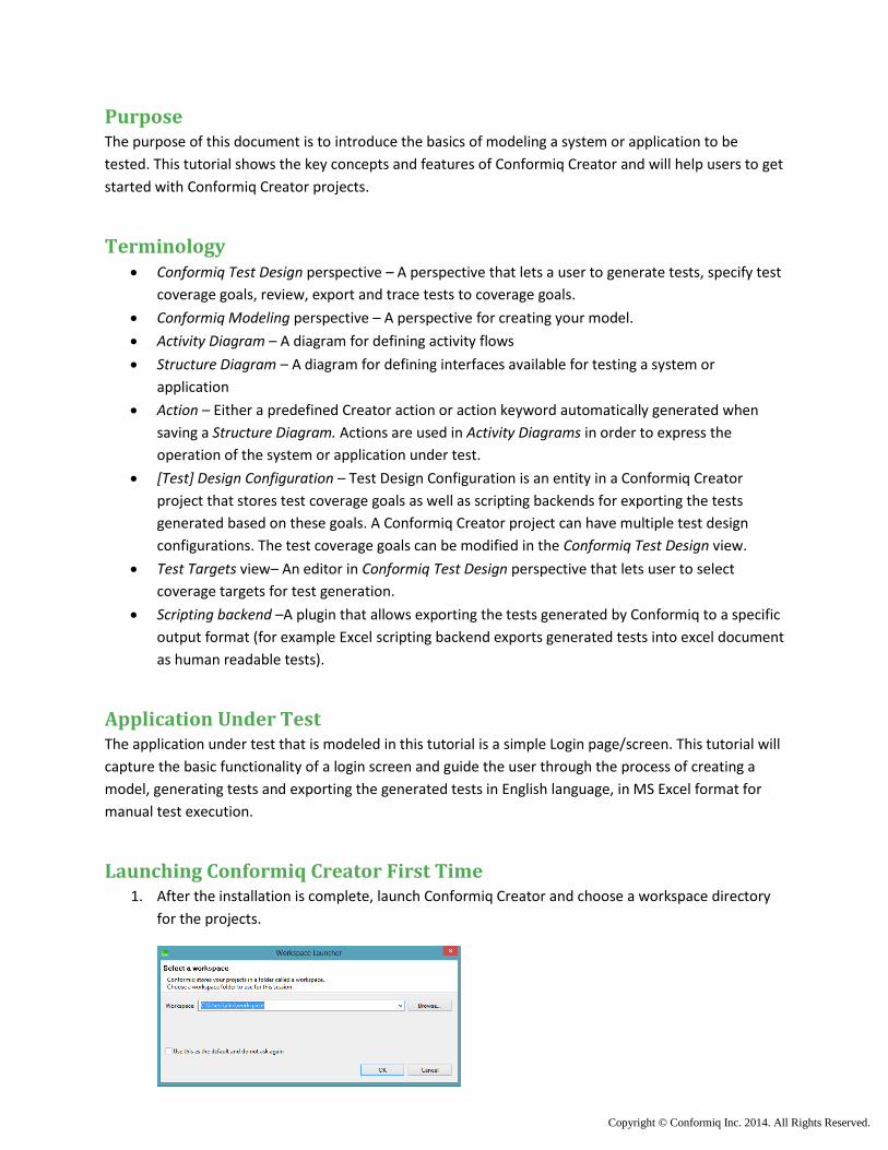
Launching Conformiq Creator First Time 1. After the installation is complete, launch Conformiq Creator and choose a workspace directory
for the projects.
Copyright © Conformiq Inc. 2014. All Rights Reserved.
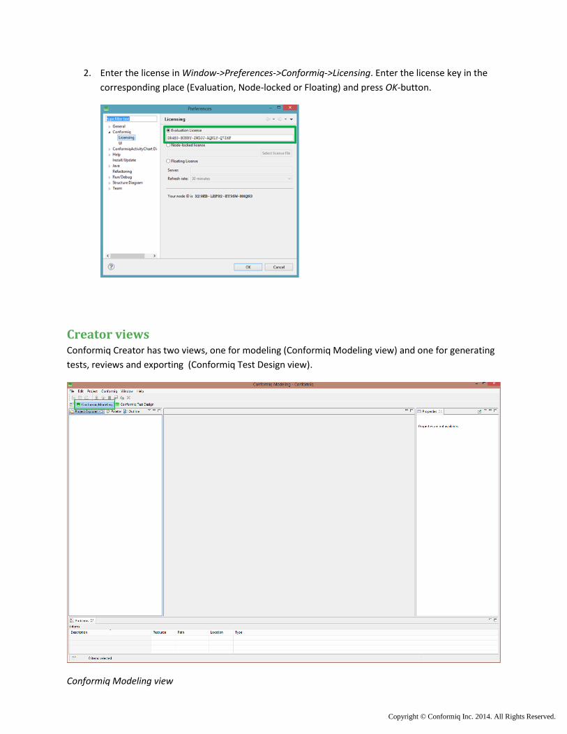
2. Enter the license in Window->Preferences->Conformiq->Licensing. Enter the license key in the
corresponding place (Evaluation, Node-locked or Floating) and press OK-button.
Creator views Conformiq Creator has two views, one for modeling (Conformiq Modeling view) and one for generating
tests, reviews and exporting (Conformiq Test Design view).
Conformiq Modeling view
Copyright © Conformiq Inc. 2014. All Rights Reserved.
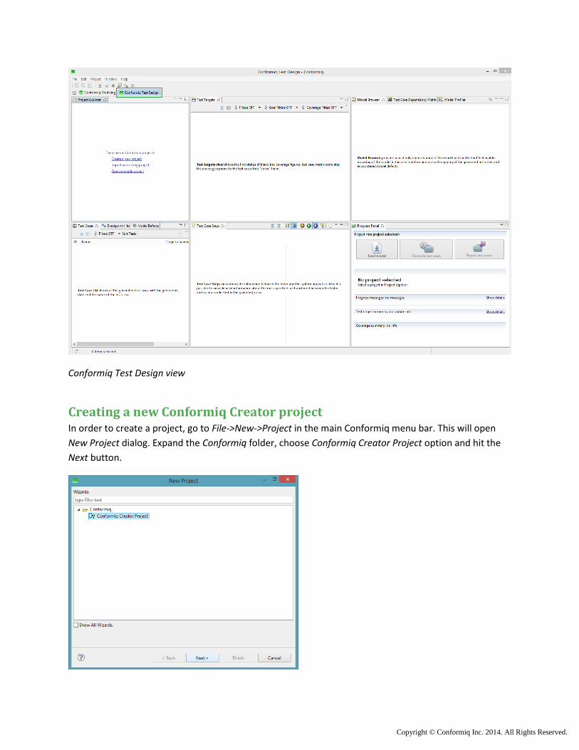
Conformiq Test Design view
Creating a new Conformiq Creator project In order to create a project, go to File->New->Project in the main Conformiq menu bar. This will open
New Project dialog. Expand the Conformiq folder, choose Conformiq Creator Project option and hit the
Next button.
Copyright © Conformiq Inc. 2014. All Rights Reserved.
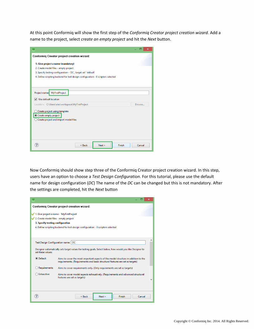
At this point Conformiq will show the first step of the Conformiq Creator project creation wizard. Add a
name to the project, select create an empty project and hit the Next button.
Now Conformiq should show step three of the Conformiq Creator project creation wizard. In this step,
users have an option to choose a Test Design Configuration. For this tutorial, please use the default
name for design configuration (DC) The name of the DC can be changed but this is not mandatory. After
the settings are completed, hit the Next button

Copyright © Conformiq Inc. 2014. All Rights Reserved.
Next Conformiq will show a Scripting Backend selection dialog. In this example the generated test cases
will be exported into human readable format in Excel document, hence select ExcelScripter.jar and press
the Finnish button.
At this moment the project should have been created. If so, the creator project has been created
successfully. If not, repeat this chapter again.
Copyright © Conformiq Inc. 2014. All Rights Reserved.
Structure Diagram The structure diagram is intended to be used for defining interfaces available for testing the given
system or application. From all of the structure diagrams in a project, Conformiq Creator automatically
generates a so called action keyword repository that is used to specify the operation of the system or
application under test in activity diagrams.
The best practice for creating models is to start with structure diagrams followed by the activity diagram
(model) and do this sequence of actions in small iterations generating test suites in between.
Creating a structure diagram
To create a structure diagram for this tutorial:
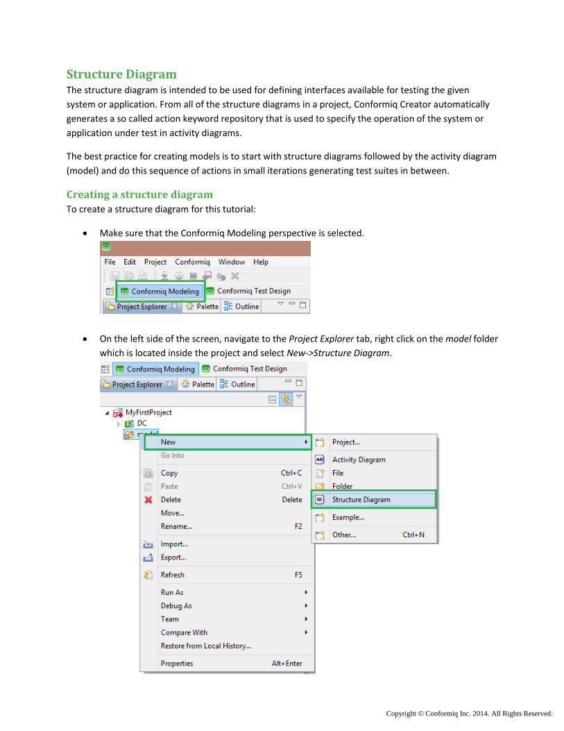
Make sure that the Conformiq Modeling perspective is selected.
On the left side of the screen, navigate to the Project Explorer tab, right click on the model folder
which is located inside the project and select New->Structure Diagram.
Copyright © Conformiq Inc. 2014. All Rights Reserved.
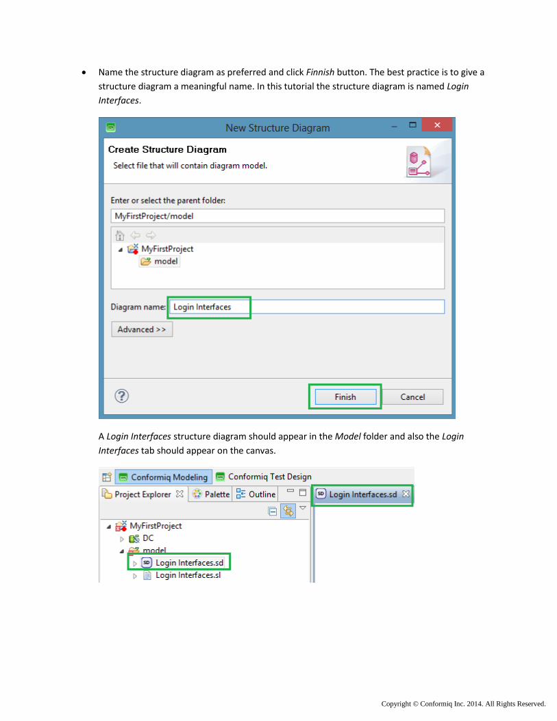
Name the structure diagram as preferred and click Finnish button. The best practice is to give a
structure diagram a meaningful name. In this tutorial the structure diagram is named Login
Interfaces.
A Login Interfaces structure diagram should appear in the Model folder and also the Login
Interfaces tab should appear on the canvas.
Copyright © Conformiq Inc. 2014. All Rights Reserved.
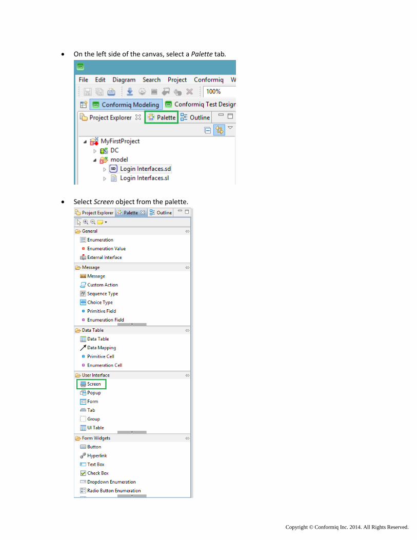
On the left side of the canvas, select a Palette tab.
Select Screen object from the palette.
Copyright © Conformiq Inc. 2014. All Rights Reserved.
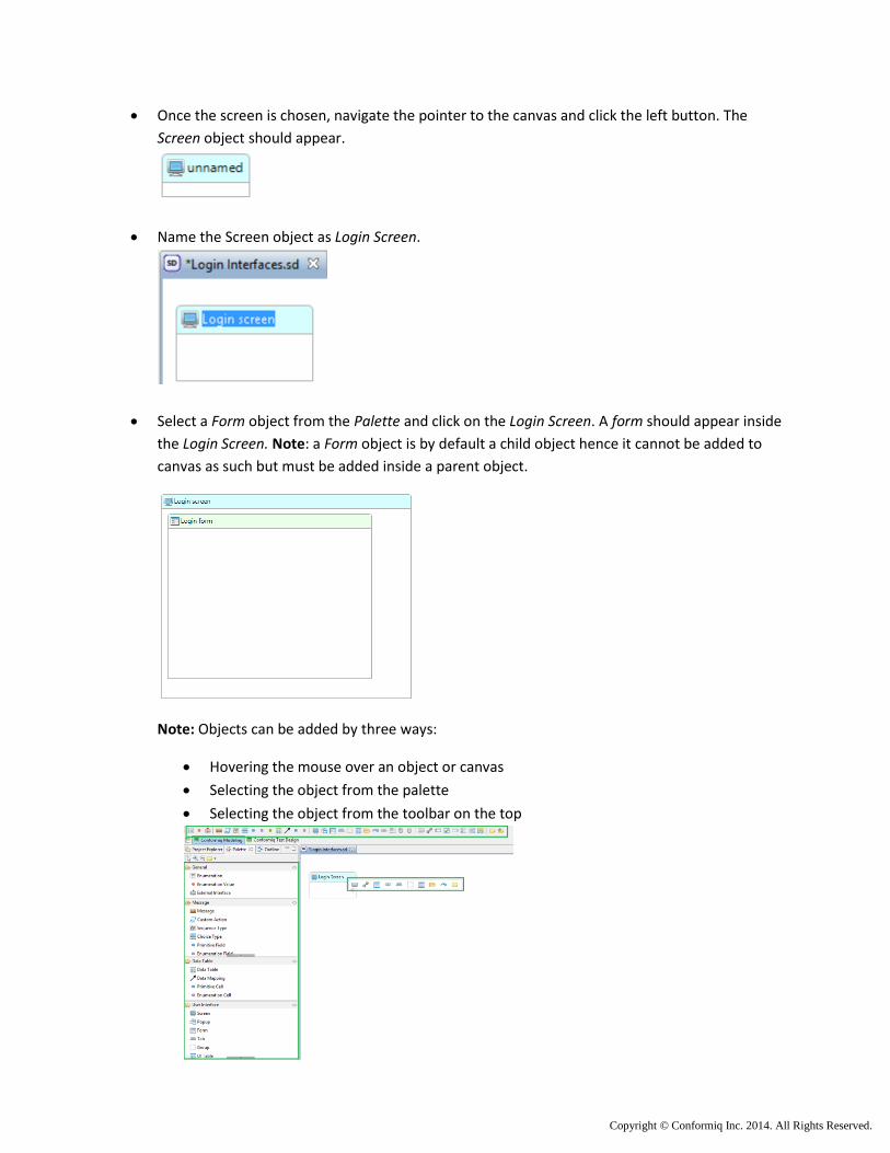
Once the screen is chosen, navigate the pointer to the canvas and click the left button. The
Screen object should appear.
Name the Screen object as Login Screen.
Select a Form object from the Palette and click on the Login Screen. A form should appear inside
the Login Screen. Note: a Form object is by default a child object hence it cannot be added to
canvas as such but must be added inside a parent object.
Note: Objects can be added by three ways:
Hovering the mouse over an object or canvas
Selecting the object from the palette
Selecting the object from the toolbar on the top
Copyright © Conformiq Inc. 2014. All Rights Reserved.
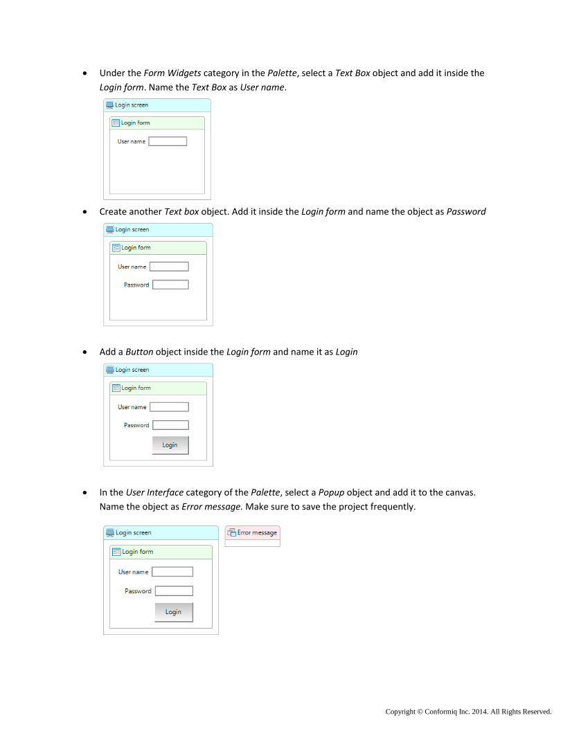
Under the Form Widgets category in the Palette, select a Text Box object and add it inside the
Login form. Name the Text Box as User name.
Create another Text box object. Add it inside the Login form and name the object as Password
Add a Button object inside the Login form and name it as Login
In the User Interface category of the Palette, select a Popup object and add it to the canvas.
Name the object as Error message. Make sure to save the project frequently.
Copyright © Conformiq Inc. 2014. All Rights Reserved.
Structure diagram properties
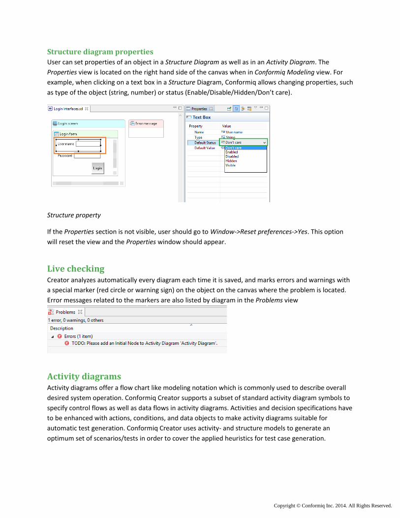
User can set properties of an object in a Structure Diagram as well as in an Activity Diagram. The
Properties view is located on the right hand side of the canvas when in Conformiq Modeling view. For
example, when clicking on a text box in a Structure Diagram, Conformiq allows changing properties, such
as type of the object (string, number) or status (Enable/Disable/Hidden/Don’t care).
Structure property
If the Properties section is not visible, user should go to Window->Reset preferences->Yes. This option
will reset the view and the Properties window should appear.
Live checking Creator analyzes automatically every diagram each time it is saved, and marks errors and warnings with
a special marker (red circle or warning sign) on the object on the canvas where the problem is located.
Error messages related to the markers are also listed by diagram in the Problems view
Activity diagrams Activity diagrams offer a flow chart like modeling notation which is commonly used to describe overall
desired system operation. Conformiq Creator supports a subset of standard activity diagram symbols to
specify control flows as well as data flows in activity diagrams. Activities and decision specifications have
to be enhanced with actions, conditions, and data objects to make activity diagrams suitable for
automatic test generation. Conformiq Creator uses activity- and structure models to generate an
optimum set of scenarios/tests in order to cover the applied heuristics for test case generation.
Copyright © Conformiq Inc. 2014. All Rights Reserved.
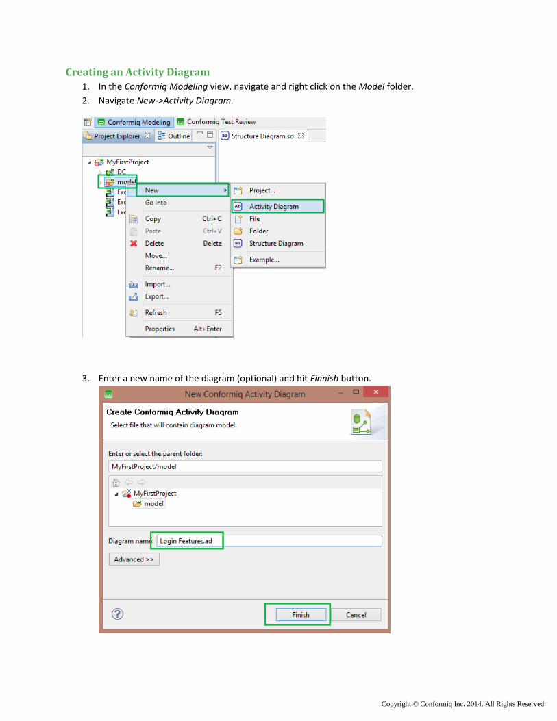
Creating an Activity Diagram
1. In the Conformiq Modeling view, navigate and right click on the Model folder.
2. Navigate New->Activity Diagram.
3. Enter a new name of the diagram (optional) and hit Finnish button.
Copyright © Conformiq Inc. 2014. All Rights Reserved.
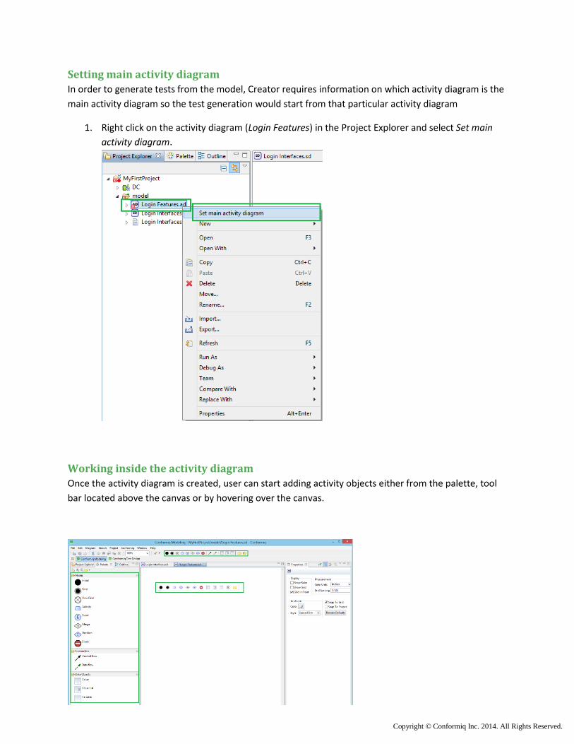
Setting main activity diagram
In order to generate tests from the model, Creator requires information on which activity diagram is the
main activity diagram so the test generation would start from that particular activity diagram
1. Right click on the activity diagram (Login Features) in the Project Explorer and select Set main
activity diagram.
Working inside the activity diagram
Once the activity diagram is created, user can start adding activity objects either from the palette, tool
bar located above the canvas or by hovering over the canvas.
Copyright © Conformiq Inc. 2014. All Rights Reserved.
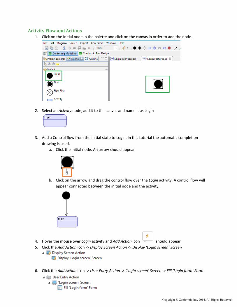
Activity Flow and Actions
1. Click on the Initial node in the palette and click on the canvas in order to add the node.
2. Select an Activity node, add it to the canvas and name it as Login
3. Add a Control flow from the initial state to Login. In this tutorial the automatic completion
drawing is used.
a. Click the initial node. An arrow should appear
b. Click on the arrow and drag the control flow over the Login activity. A control flow will
appear connected between the initial node and the activity.
4. Hover the mouse over Login activity and Add Action icon should appear
5. Click the Add Action icon -> Display Screen Action -> Display ‘Login screen’ Screen
6. Click the Add Action icon -> User Entry Action -> ‘Login screen’ Screen -> Fill ‘Login form’ Form
Copyright © Conformiq Inc. 2014. All Rights Reserved.
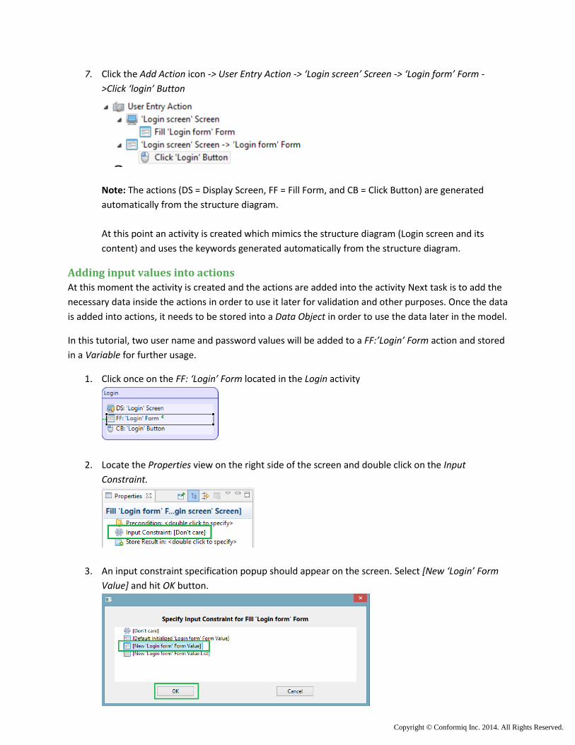
7. Click the Add Action icon -> User Entry Action -> ‘Login screen’ Screen -> ‘Login form’ Form -
>Click ‘login’ Button
Note: The actions (DS = Display Screen, FF = Fill Form, and CB = Click Button) are generated
automatically from the structure diagram.
At this point an activity is created which mimics the structure diagram (Login screen and its
content) and uses the keywords generated automatically from the structure diagram.
Adding input values into actions
At this moment the activity is created and the actions are added into the activity Next task is to add the
necessary data inside the actions in order to use it later for validation and other purposes. Once the data
is added into actions, it needs to be stored into a Data Object in order to use the data later in the model.
In this tutorial, two user name and password values will be added to a FF:’Login’ Form action and stored
in a Variable for further usage.
1. Click once on the FF: ‘Login’ Form located in the Login activity
2. Locate the Properties view on the right side of the screen and double click on the Input
Constraint.
3. An input constraint specification popup should appear on the screen. Select [New ‘Login’ Form
Value] and hit OK button.

Copyright © Conformiq Inc. 2014. All Rights Reserved.
The Properties tab of the Fill ‘Login’ Form should look like the picture below
4. In the Properties tab, under Input Constraint ‘Login’ Form Value; enter two user name and
password values. In this tutorial the user names will be “GoodName” and “BadName”, and
passwords will be “GoodPassword” and “BadPassword”. To add multiple values, click on the
<click to add alternatives> and add the next value.
Note: A user has also option to specify data coverage conditions. This option occurs only when
value lists or alternate input values are specified. The options of the data coverage are shown
below.
Copyright © Conformiq Inc. 2014. All Rights Reserved.
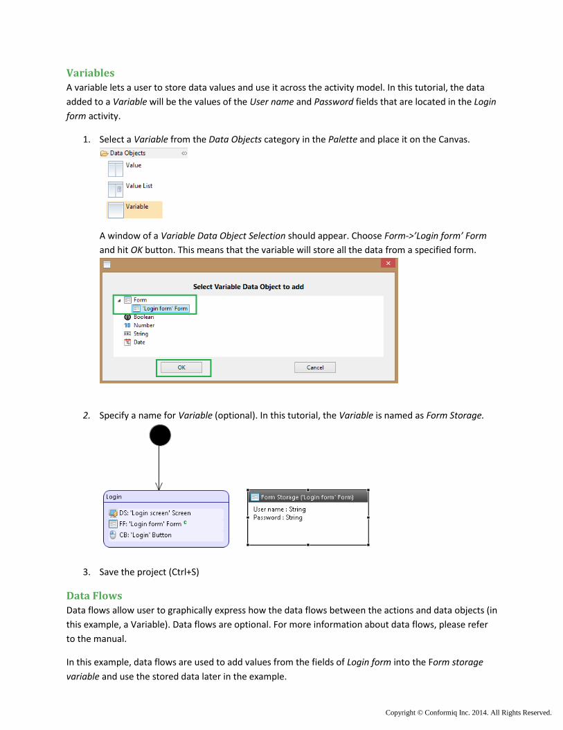
Variables
A variable lets a user to store data values and use it across the activity model. In this tutorial, the data
added to a Variable will be the values of the User name and Password fields that are located in the Login
form activity.
1. Select a Variable from the Data Objects category in the Palette and place it on the Canvas.
A window of a Variable Data Object Selection should appear. Choose Form->’Login form’ Form
and hit OK button. This means that the variable will store all the data from a specified form.
2. Specify a name for Variable (optional). In this tutorial, the Variable is named as Form Storage.
3. Save the project (Ctrl+S)
Data Flows
Data flows allow user to graphically express how the data flows between the actions and data objects (in
this example, a Variable). Data flows are optional. For more information about data flows, please refer
to the manual.
In this example, data flows are used to add values from the fields of Login form into the Form storage
variable and use the stored data later in the example.
Copyright © Conformiq Inc. 2014. All Rights Reserved.
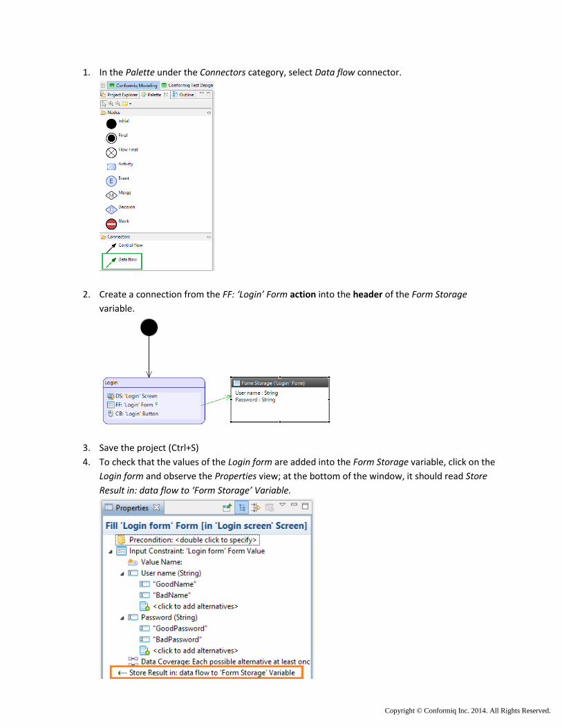
1. In the Palette under the Connectors category, select Data flow connector.
2. Create a connection from the FF: ‘Login’ Form action into the header of the Form Storage
variable.
3. Save the project (Ctrl+S)
4. To check that the values of the Login form are added into the Form Storage variable, click on the
Login form and observe the Properties view; at the bottom of the window, it should read Store
Result in: data flow to ‘Form Storage’ Variable.
Copyright © Conformiq Inc. 2014. All Rights Reserved.
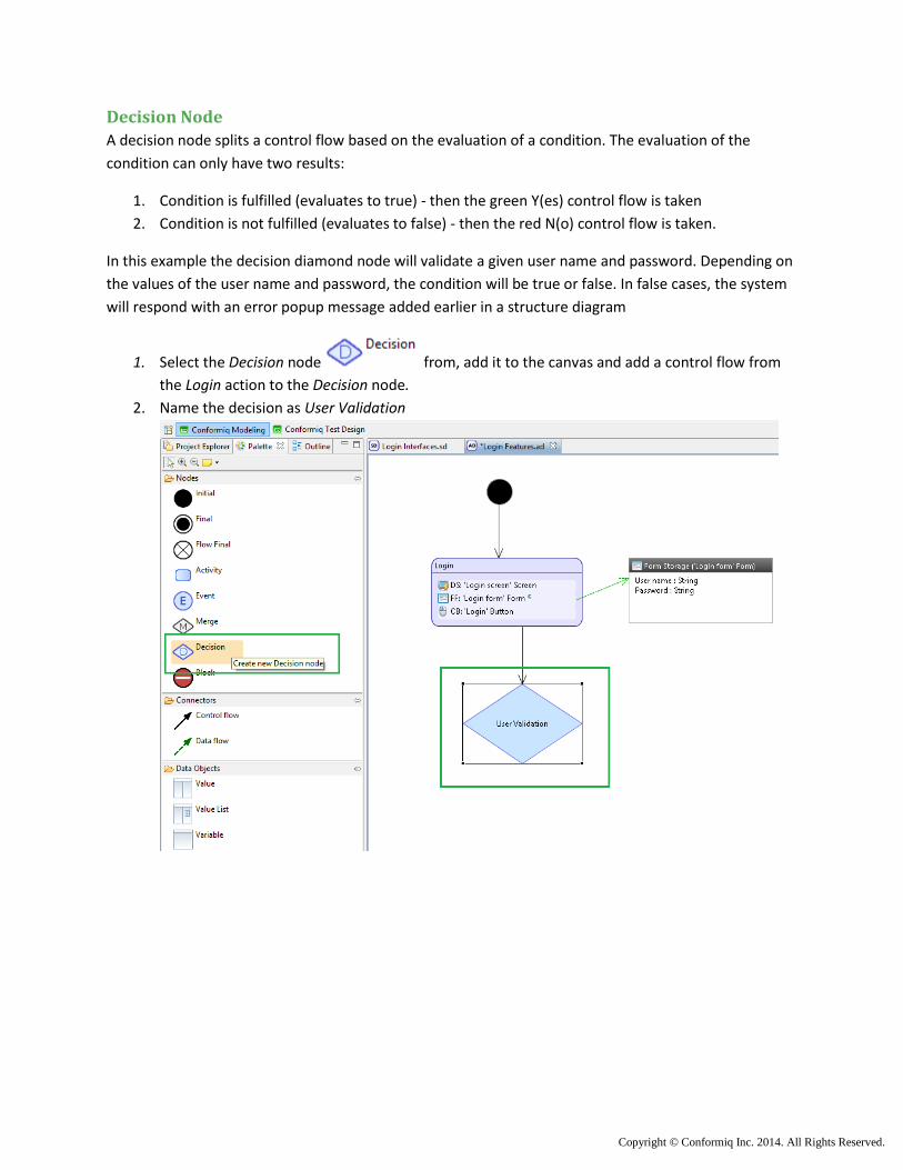
Decision Node
A decision node splits a control flow based on the evaluation of a condition. The evaluation of the
condition can only have two results:
1. Condition is fulfilled (evaluates to true) - then the green Y(es) control flow is taken
2. Condition is not fulfilled (evaluates to false) - then the red N(o) control flow is taken.
In this example the decision diamond node will validate a given user name and password. Depending on
the values of the user name and password, the condition will be true or false. In false cases, the system
will respond with an error popup message added earlier in a structure diagram
1. Select the Decision node from, add it to the canvas and add a control flow from
the Login action to the Decision node.
2. Name the decision as User Validation
Copyright © Conformiq Inc. 2014. All Rights Reserved.
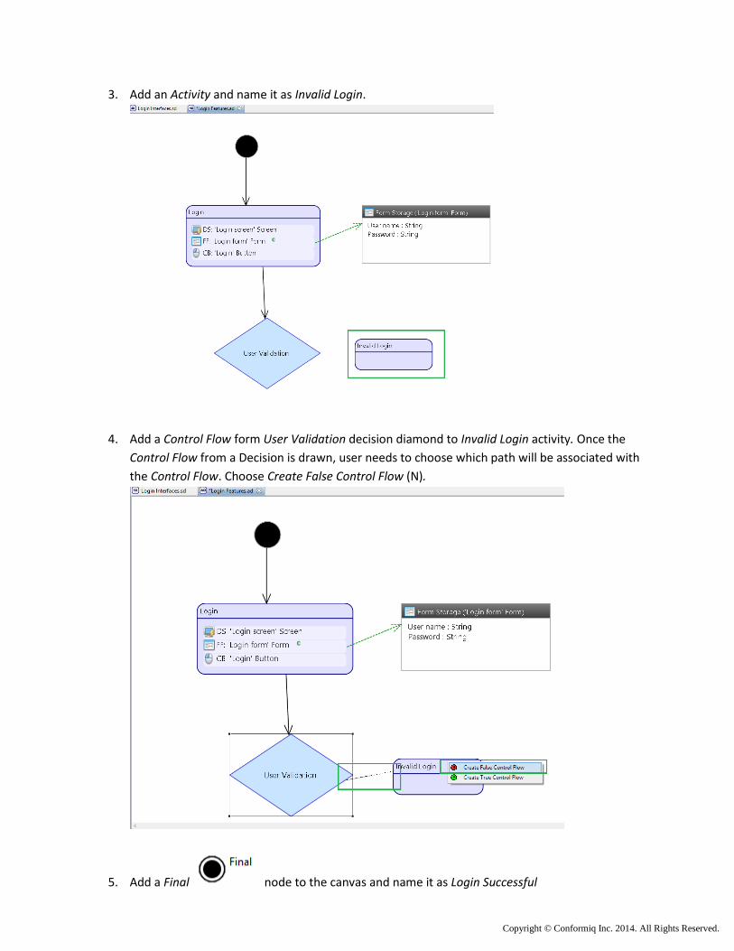
3. Add an Activity and name it as Invalid Login.
4. Add a Control Flow form User Validation decision diamond to Invalid Login activity. Once the
Control Flow from a Decision is drawn, user needs to choose which path will be associated with
the Control Flow. Choose Create False Control Flow (N).
5. Add a Final node to the canvas and name it as Login Successful
Copyright © Conformiq Inc. 2014. All Rights Reserved.
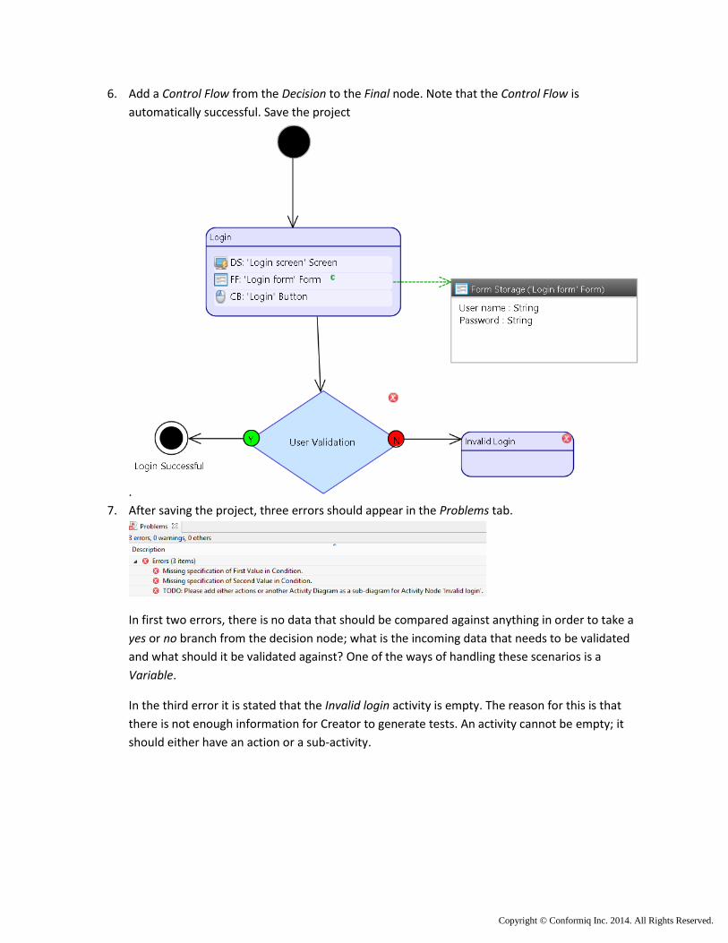
6. Add a Control Flow from the Decision to the Final node. Note that the Control Flow is
automatically successful. Save the project
.
7. After saving the project, three errors should appear in the Problems tab.
In first two errors, there is no data that should be compared against anything in order to take a
yes or no branch from the decision node; what is the incoming data that needs to be validated
and what should it be validated against? One of the ways of handling these scenarios is a
Variable.
In the third error it is stated that the Invalid login activity is empty. The reason for this is that
there is not enough information for Creator to generate tests. An activity cannot be empty; it
should either have an action or a sub-activity.
Copyright © Conformiq Inc. 2014. All Rights Reserved.
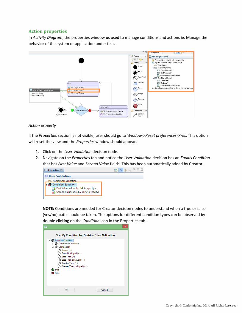
Action properties
In Activity Diagram, the properties window us used to manage conditions and actions ie. Manage the
behavior of the system or application under test.
Action property
If the Properties section is not visible, user should go to Window->Reset preferences->Yes. This option
will reset the view and the Properties window should appear.
1. Click on the User Validation decision node.
2. Navigate on the Properties tab and notice the User Validation decision has an Equals Condition
that has First Value and Second Value fields. This has been automatically added by Creator.
NOTE: Conditions are needed for Creator decision nodes to understand when a true or false
(yes/no) path should be taken. The options for different condition types can be observed by
double clicking on the Condition icon in the Properties tab.
Copyright © Conformiq Inc. 2014. All Rights Reserved.
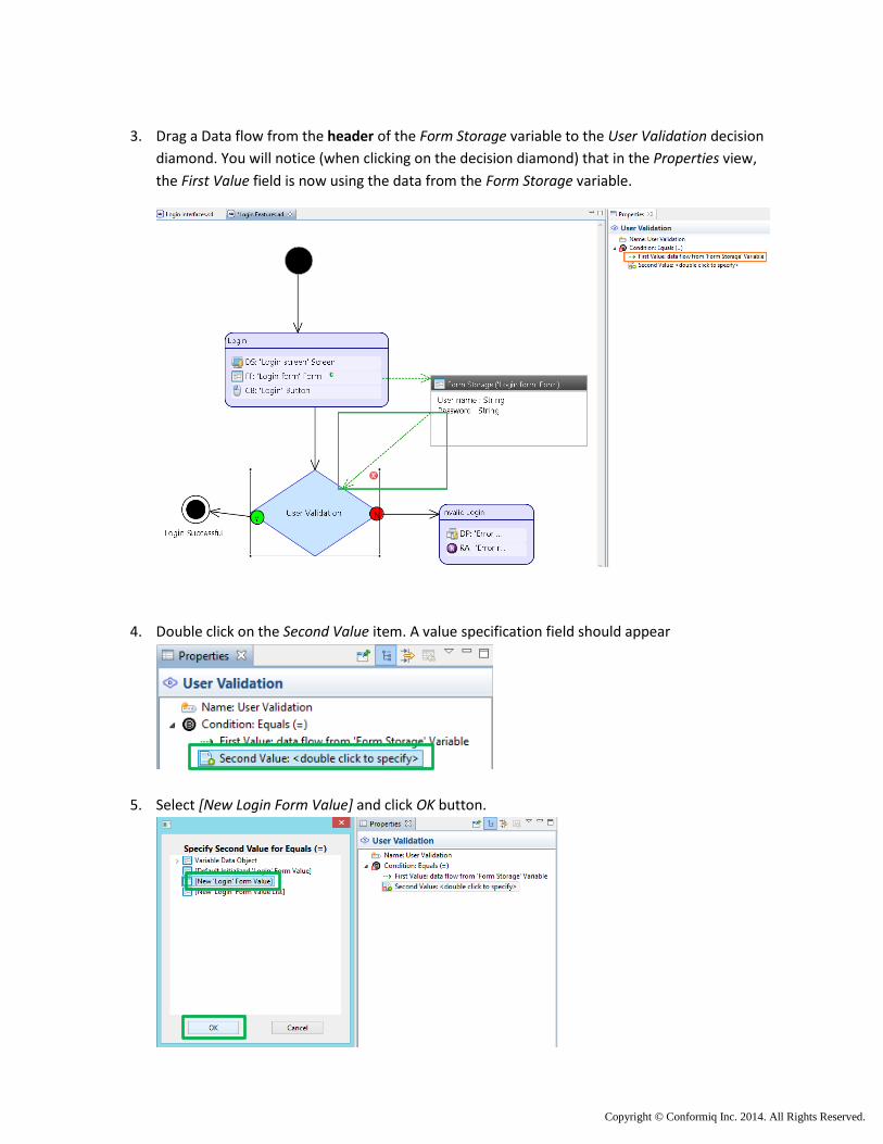
3. Drag a Data flow from the header of the Form Storage variable to the User Validation decision
diamond. You will notice (when clicking on the decision diamond) that in the Properties view,
the First Value field is now using the data from the Form Storage variable.
4. Double click on the Second Value item. A value specification field should appear
5. Select [New Login Form Value] and click OK button.
Copyright © Conformiq Inc. 2014. All Rights Reserved.
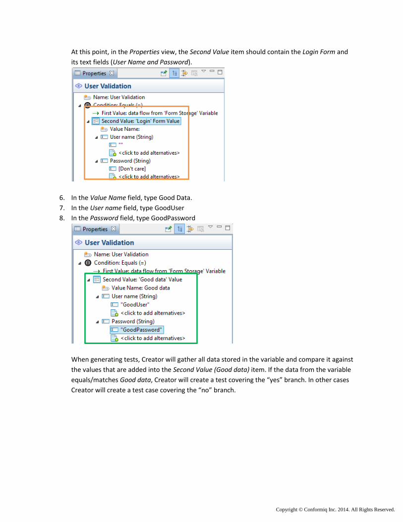
At this point, in the Properties view, the Second Value item should contain the Login Form and
its text fields (User Name and Password).
6. In the Value Name field, type Good Data.
7. In the User name field, type GoodUser
8. In the Password field, type GoodPassword
When generating tests, Creator will gather all data stored in the variable and compare it against
the values that are added into the Second Value (Good data) item. If the data from the variable
equals/matches Good data, Creator will create a test covering the “yes” branch. In other cases
Creator will create a test case covering the “no” branch.
Copyright © Conformiq Inc. 2014. All Rights Reserved.
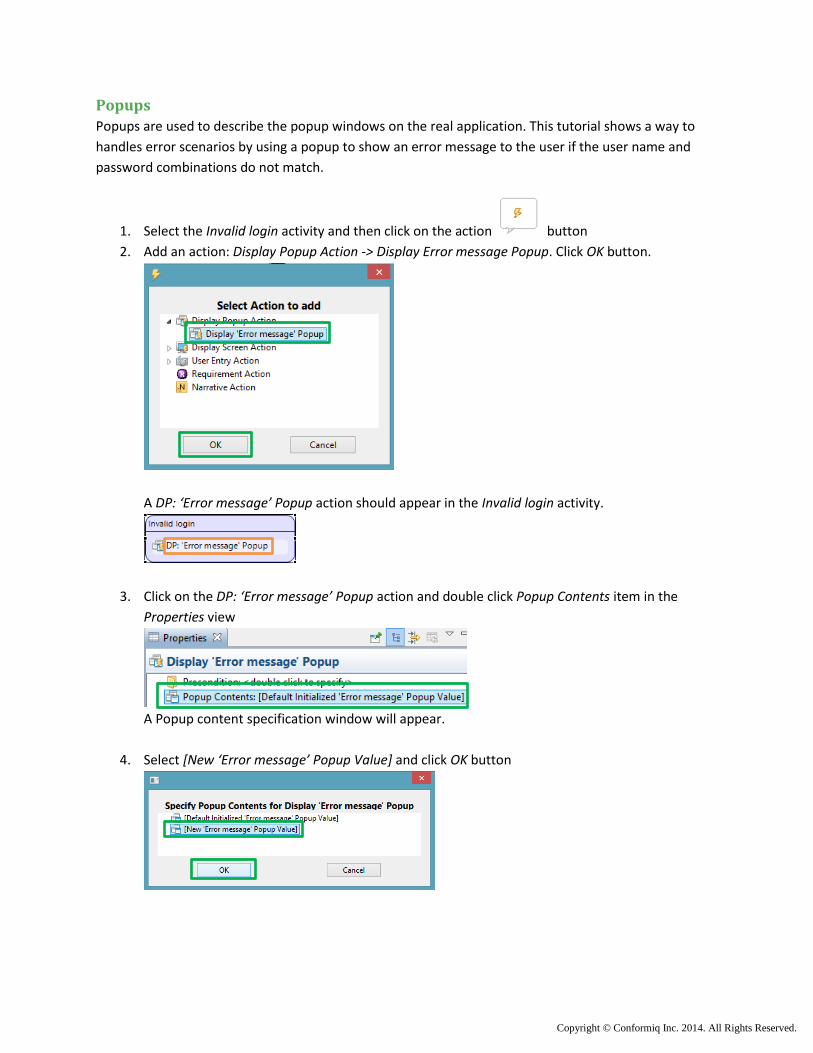
Popups
Popups are used to describe the popup windows on the real application. This tutorial shows a way to
handles error scenarios by using a popup to show an error message to the user if the user name and
password combinations do not match.
1. Select the Invalid login activity and then click on the action button
2. Add an action: Display Popup Action -> Display Error message Popup. Click OK button.
A DP: ‘Error message’ Popup action should appear in the Invalid login activity.
3. Click on the DP: ‘Error message’ Popup action and double click Popup Contents item in the
Properties view
A Popup content specification window will appear.
4. Select [New ‘Error message’ Popup Value] and click OK button

Copyright © Conformiq Inc. 2014. All Rights Reserved.
5. In the Properties window, enter the error text in the ‘Error message’ Text field. In this tutorial
the added text is “Wrong user name or password. Please try again”.
Adding requirements to a model
In Creator, requirements may be added inside an activity. Once the requirements are added to the
model (activity diagram) they become targets for test generation. Also, a traceability matrix between
the requirements and generated tests will be created automatically.
In this tutorial the requirement will be added as written in a specification. The requirement name is “The
will system should show an error message if the login is incorrect”. In order to fulfill the requirement, an
error handling logic be described in the activity diagram.
1. Select the Invalid Login activity and click on the action button.
2. Select Requirement Action from the action selector and press OK button.
3. In the Properties view, add in the Requirement Identifier - “The system should show an error
message if the login is incorrect” and save the project.
Copyright © Conformiq Inc. 2014. All Rights Reserved.
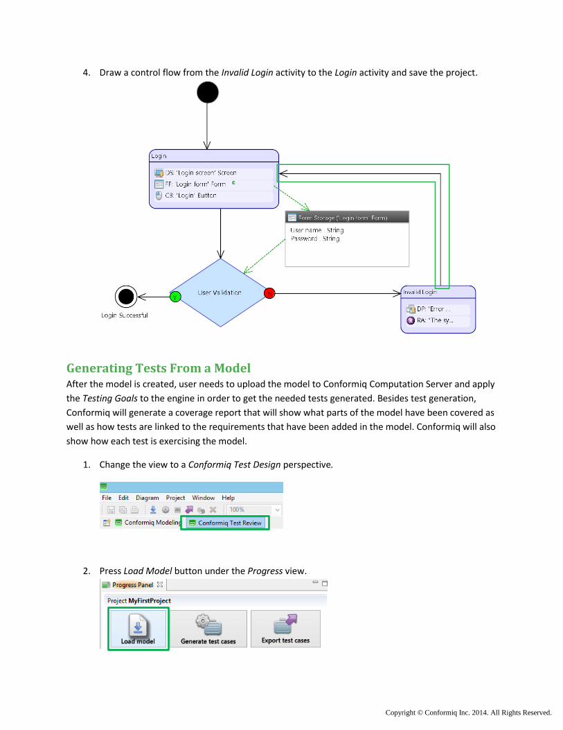
4. Draw a control flow from the Invalid Login activity to the Login activity and save the project.
Generating Tests From a Model After the model is created, user needs to upload the model to Conformiq Computation Server and apply
the Testing Goals to the engine in order to get the needed tests generated. Besides test generation,
Conformiq will generate a coverage report that will show what parts of the model have been covered as
well as how tests are linked to the requirements that have been added in the model. Conformiq will also
show how each test is exercising the model.
1. Change the view to a Conformiq Test Design perspective.
2. Press Load Model button under the Progress view.
Copyright © Conformiq Inc. 2014. All Rights Reserved.
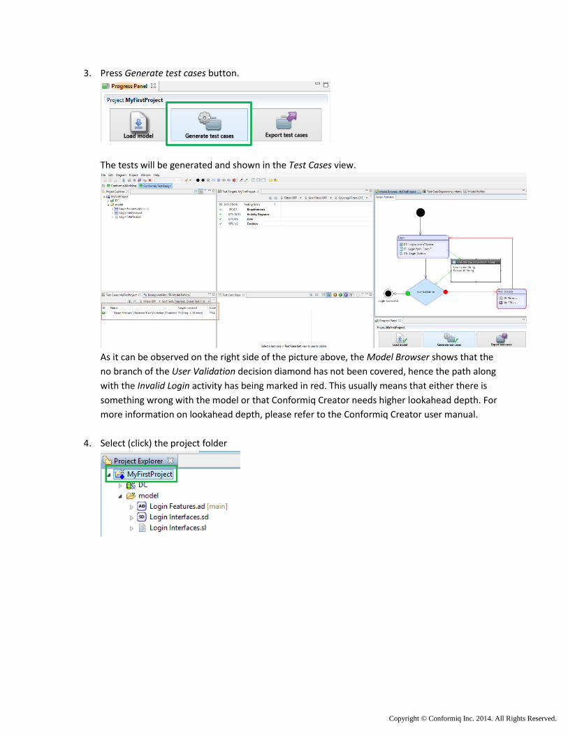
3. Press Generate test cases button.
The tests will be generated and shown in the Test Cases view.
As it can be observed on the right side of the picture above, the Model Browser shows that the
no branch of the User Validation decision diamond has not been covered, hence the path along
with the Invalid Login activity has being marked in red. This usually means that either there is
something wrong with the model or that Conformiq Creator needs higher lookahead depth. For
more information on lookahead depth, please refer to the Conformiq Creator user manual.
4. Select (click) the project folder
Copyright © Conformiq Inc. 2014. All Rights Reserved.
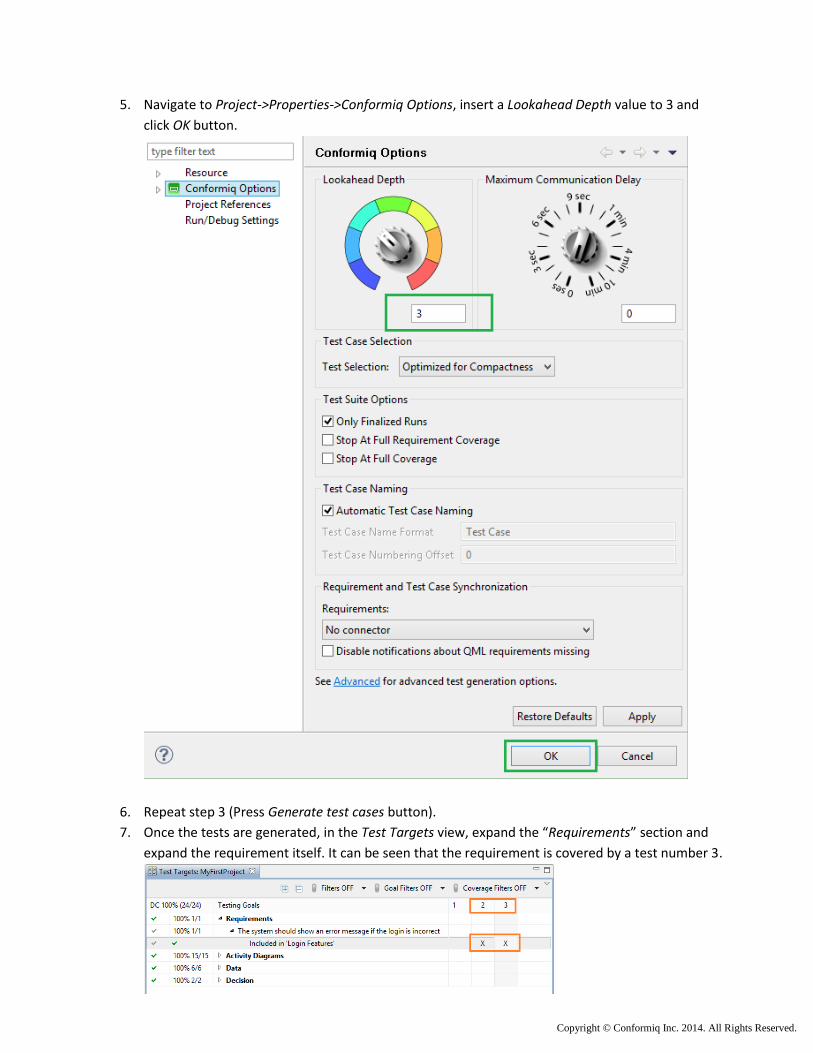
5. Navigate to Project->Properties->Conformiq Options, insert a Lookahead Depth value to 3 and
click OK button.
6. Repeat step 3 (Press Generate test cases button).
7. Once the tests are generated, in the Test Targets view, expand the “Requirements” section and
expand the requirement itself. It can be seen that the requirement is covered by a test number 3.

Copyright © Conformiq Inc. 2014. All Rights Reserved.
8. In the Test Targets view, click on the column number 1 (i.e. the first test case). The test will be
selected and shown as message sequence diagram. The model browser will show how the test is
exercising the model.
9. In order to review tests and data generated in the test, double click on the test step/arrow in
the test step view. The input/output values generated on the particular test step, will be shown
on the right side of the test step view. Also the model browser will highlight the action/activity
that is exercised at the particular test step.
Copyright © Conformiq Inc. 2014. All Rights Reserved.
Exporting tests from Creator The generated tests can be exported into various formats for manual or automated test execution. The
generated test suit can also be uploaded to an ALM/test management system. In this tutorial, tests are
exported into Excel spread sheet in human readable format (English).
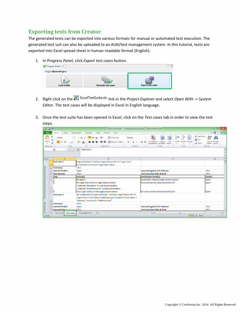
1. In Progress Panel, click Export test cases button.
2. Right click on the link in the Project Explorer and select Open With -> System
Editor. The test cases will be displayed in Excel in English language.
3. Once the test suite has been opened in Excel, click on the Test cases tab in order to view the test
steps.