Embed Size (px)
Citation preview

Configuration and Management of
Networks
2012
Pedro Amaral

Configuration and Management of Networks 2012
Service Provider Networks
Carrier grade networks that carry customers traffic:
• Triple play residential customers
• Voice
• High Speed Internet
• Broadcast TV and Video on Demand
• Mobile Backhaul • Interconnection of the RAN
(Radio Access Network)
• Enterprise Services
• Enterprise inter-‐‑branch WAN connections
• Data center networks (Cloud) interconnection

Configuration and Management of Networks
Service Provider Networks
White Paper
© 2008 Cisco Systems, Inc. All rights reserved. This document is Cisco Public Information. Page 7 of 15
● Policy/service layer: Provides broadband policy management to control service delivery – a key component of the Service Exchange Framework.
Figure 2. IP NGN Carrier Ethernet Design
Access The access component of the network provides physical wired or wireless access to subscribers. The Carrier Ethernet network must provide transport for all types of access networks and devices, including SONET and SDH MSPP networks, cable, DSL, PON, E-FTTx, WiMAX, 3G Wireless, and Wi-Fi hotspot and hotzone networks. Furthermore, services must be crafted based on the type of customer and the type of access network.
Carrier Ethernet Aggregation The Carrier Ethernet aggregation network is the foundation of the IP NGN Carrier Ethernet Design. It provides Ethernet transport for all types of services, customers, and access technologies, and scales to support the transport of 1-Gbps to 10-Gbps line-rate services and will evolve to 100-Gbps capacity and beyond . The Carrier Ethernet Design allows all services to be optimized independently, by supporting multiple Layer 2/Layer 3 technologies in the Ethernet transport network. These technologies and/or protocols include:
● Layer 3 routing with PIM-SSM ● Layer 3 MPLS VPN and multicast VPN (RFC 2547bis) ● H-VPLS

Configuration and Management of Networks 2012
Service Provider Networks
• Access: Provides access to residential and business customers over DSL, fiber, cable, or wireless.
• Carrier Ethernet aggregation: Aggregates the access network
across a Carrier Ethernet network and provides interconnectivity to the IP/MPLS edge and IP/MPLS core.
• Intelligent service edge: Interfaces services with the IP/MPLS
core; this is the provider edge for both residential and business subscriber services.
• IP/MPLS core: Provides scalable IP/MPLS routing in the core network.
• Policy/service layer: Provides broadband policy management to control service delivery – a key component of the Service Exchange Framework.

Configuration and Management of Networks 2012
Service Provider Networks
• Carrier Ethernet Aggregation -‐‑ Multiple Layer 2/Layer 3 technologies for Ethernet transport.
• Layer 3 routing with PIM-‐‑SSM
• Layer 3 MPLS VPN and multicast VPN (RFC 2547bis)
• H-‐‑VPLS
• EoMPLS (Pseudowires)
• IEEE 802.1q (VLANS), 802.1ad(QinQ), 802.1ah (PBB) Applications have different requirements that can not be addressed by a single, universal approach to network design

Configuration and Management of Networks 2012
Service Provider Networks – Protocols by service
White Paper
© 2008 Cisco Systems, Inc. All rights reserved. This document is Cisco Public Information. Page 8 of 15
● EoMPLS (Pseudowires) ● IEEE 802.1q, 802.1ad, 802.1ah ● IPoDWDM
One reason that it is critical to support multiple protocols in the aggregation network is that different customers, services, and applications have different requirements that can not be addressed by a single, universal approach to network design. Another reason that multiple protocols and technologies must be supported is that service providers have unique approaches to network architecture and design. The flexibility of the IP NGN Carrier Ethernet design allows service providers to design the network according to their own design guidelines and architecture, not those of any particular vendor.
Any of the protocols specified earlier can be used for any service with the exception of residential video broadcast service. Because of the critical quality of experience (QoE) requirements for video broadcast services, the optimal delivery technology is Layer 3 IP multicast with PIM-SSM over MPLS with Fast Reroute (FRR). This provides a highly scalable and reliable architecture for broadcast TV service. Similarly, wholesale residential broadcast video service should use Layer 3 multicast over an MPLS VPN (RFC 2547bis) to provide both scalability and logical separation from other retail networks and customers.
While service providers are free to choose transport protocols that best suit their network architecture and applications, Cisco does offer recommended protocols to optimize service delivery (Table 1). In general, EoMPLS Pseudowire transport is recommended for many services that require Ethernet transport with differentiated QoS. Because EoMPLS uses IETF Pseudowire standards, it is not only scalable, but also delivers enhanced QoS characteristics.
Table 1. Recommended Protocols for Different Services
Service Recommended Transport Protocols Transport Function
Residential High-Speed Internet
EoMPLS or IEEE 802.1ad Backhaul Internet traffic from the access network to the Broadband Remote Access Router for AAA and service control. Provide QoS, tiered, quota-based, and usage-based Internet access.
Residential VoIP EoMPLS or Layer 3 IP Routing over MPLS FRR
Connect signaling traffic to softswitch and RTP traffic to Internet or core IP network. Provide QoS.
Residential IPTV Layer 3 PIM SSM over MPLS FRR Broadcast TV service with massive scalability, fast recovery from failures, and excellent QoE.
Residential Video on Demand
Layer 3 IP Routing over MPLS FRR
Video-on-demand service with massive scalability, fast recovery from failures, and excellent QoE.
Business Ethernet Private Line (EPL)
EoMPLS or IEEE 802.1ad Transport of Ethernet circuit at full data rate with no statistical multiplexing. This requires QoS.
Business Ethernet Virtual Private Line (EVPL)
EoMPLS or IEEE 802.1ad Transport of Ethernet Virtual Connection with CIR/EIR and statistical multiplexing gain.
Business MPLS VPN MPLS or IEEE 802.1ad Transport of subscriber Ethernet Virtual Connection to MSE router that is the provider edge of the MPLS VPN service. CIR/EIR guarantees bandwidth.
Business E-LAN H-VPLS or IEEE 802.1ad Multipoint virtual LAN service for business customers. CIR/EIR guarantees bandwidth.
Mobile Backhaul EoMPLS or IEEE 802.1ad Pseudowire backhaul for 3G, WiMAX, and Wi-Fi networks.
Wholesale Residential High-Speed Internet
EoMPLS or IEEE 802.1ad Pseudowire backhaul from the access network to the retail service provider.
Wholesale IPTV and VoD RFC 2547bis MPLS VPN with multicast
Private IP network with multicast that interconnects the retail service provider with the access network.
Wholesale Business Services
EoMPLS or IEEE 802.1ad Provide transport from the business customer to the retail service provider with EIR/CIR bandwidth guaranties.

Configuration and Management of Networks 2012
Service Provider Networks
Carrier Ethernet Networks
Ethernet Service Definition according to the Metro Ethernet Forum: • User-‐‑to-‐‑Network Interface (UNI) – Point of demarcation to the customer. • Ethernet Virtual Connection (EVC) – Association of two or more UNIs
Two main service types : • Ethernet Line Service (ELS)—This is basically a point-‐‑to-‐‑point (P2P) Ethernet
service. • Ethernet LAN Service (E-‐‑LAN)—This is a multipoint-‐‑to-‐‑multipoint (MP2MP)
Ethernet.

Configuration and Management of Networks 2012
Service Provider Networks – Ethernet Challenges
NSN JN
CIS-S
P 12
- 15
, Nov
. 201
2
Junos Service Provider Switching
Chapter 2–8 • Carrier Ethernet www.juniper.net
Scalability
Allowing an Ethernet WAN to scale has always posed a challenge to the service provider. For
instance, for an Ethernet switch to forward Ethernet frames it must learn the MAC address of each of
the end stations on the customer network. For a service provider serving thousands of customers,
this need might mean that the service provider-owned switches must potentially learn millions of
MAC addresses. Also, when redundant links exist between the service provider and its customers for
resiliency purposes, the question arises, “How can you prevent a loop?” The spanning tree protocols
of today simply cannot scale to prevent the loops of thousands of customer sites.
Service-Level Agreements
Usually when a customer purchases WAN service, service-level agreements (SLAs) are in place to
ensure that the service provider provides a good service to the customer. Common SLAs would cover
frame delay and frame loss.
Continued on the next page.
Configuration and Management of Networks 2012
Service Provider Networks
NSN JN
CIS-S
P 12
- 15
, Nov
. 201
2
Junos Service Provider Switching
www.juniper.net Carrier Ethernet • Chapter 2–23
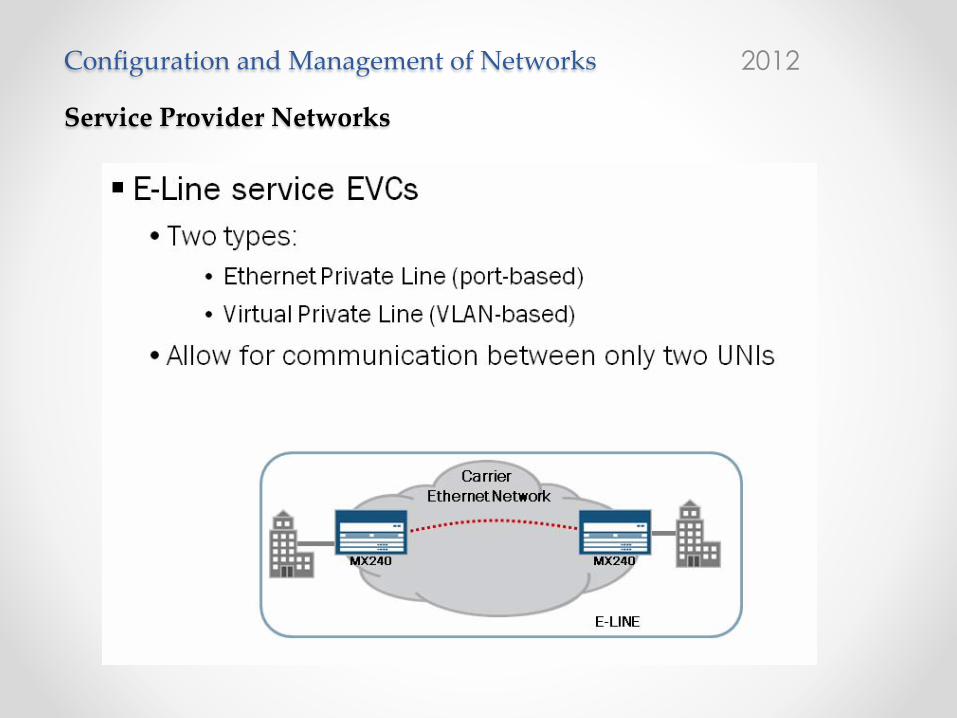
E-Line Service EVCA point-to-point EVC is referred to as an Ethernet Line (E-Line) EVC. It provides connectivity between only two UNIs. Two types of E-Line EVCs exist. An Ethernet Private Line EVC is port-based, where each of the UNIs is a dedicated port to a customer. All virtual LANs (VLANs) for the UNI can traverse the EVC. A Virtual Private Line EVC is VLAN-based, such that it allows for the mapping of individual VLANs to the EVC. This mapping allows the service provider to multiplex multiple customers using a single access port.
Configuration and Management of Networks 2012
Service Provider Networks
NSN JN
CIS-S
P 12
- 15
, Nov
. 201
2
Junos Service Provider Switching
Chapter 2–24 • Carrier Ethernet www.juniper.net
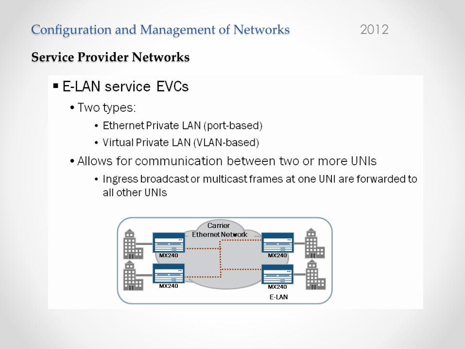
E-LAN Service EVCsMultipoint-to-multipoint EVCs are referred to as Ethernet LAN (E-LAN) EVCs. Essentially, an E-LAN EVC makes the service provider network appear to be a single broadcast domain to the customer. E-LAN EVCs come in the form of either an Ethernet Private LAN or Virtual Private LAN, similar to the E-Line EVC.

Configuration and Management of Networks 2012
Service Provider Networks
NSN JN
CIS-S
P 12
- 15
, Nov
. 201
2
Junos Service Provider Switching
Chapter 2–26 • Carrier Ethernet www.juniper.net
MEF’s Three-Layer ModelThe MEF has defined a three-layer model for carrier Ethernet networks. The Application Services Layer supports end-user applications. The Ethernet Services Layer carries the applications. This layer is the main focus of the MEF. Carrier Ethernet resides on the Ethernet Services Layer. To deliver the Ethernet services, the Transport Services Layer uses various networking and media types. This layer includes technologies like provider backbone bridging, virtual private LAN service (VPLS), and SONET. As shown on the slide, each layer of the MEF model has its own data, control, and management planes.

Configuration and Management of Networks 2012
Service Provider Networks – Carrier Ethernet
NSN JN
CIS-S
P 12
- 15
, Nov
. 201
2
Junos Service Provider Switching
Chapter 5–4 • Provider Bridging www.juniper.net
Scaling Customer Bridged Networks
IEEE 802.1Q VLAN tagging makes it possible for a customer’s bridged network to scale. Instead of
needing to add more bridging equipment to a growing network, VLAN tagging allows for the logical
separation of a bridged network into many broadcast domains (or VLANs). With a 12-bit length VLAN
ID, 4094 VLANs are available for use on a single physical Ethernet network.
Ethernet from Service Providers
Because of its simple nature, service provider customers generally understand Ethernet. For a long
time, service providers have searched for ways to deliver Ethernet Virtual Circuits (EVCs) to the
customer premises. To a customer, an EVC between two sites should appear as a simple Ethernet
link or VLAN through the service provider’s network. IEEE 802.1Q VLAN tagging does not provide the
scalability (in the service provider network) for a service provider to deliver that type of service.
Continued on the next page.

Configuration and Management of Networks 2012
Service Provider Networks – Carrier Ethernet
NSN JN
CIS-S
P 12
- 15
, Nov
. 201
2
Junos Service Provider Switching
Chapter 5–6 • Provider Bridging www.juniper.net
IEEE 802.1ad
IEEE 802.1ad, also known as Q-in-Q tunneling, has standardized the methodology of stacking VLAN tags. The slide shows the frame format that the standard introduced. The standard gives a new name to the 802.1Q VLAN tag: the Customer VLAN (C-VLAN) tag (C-TAG). It also introduces a new tag named the Service VLAN (S-VLAN) tag (S-TAG). By adding the S-TAG to the frame, much less coordination is necessary between the customer and the service provider. At the customer site, the customer can continue to use 802.1Q tagging using C-VLAN IDs that are relevant only to their network (not the service provider’s network). As 802.1Q-tagged frames arrive at the edge of the service provider’s bridged network, the provider edge bridge (PEB) adds an S-TAG to the frame. The S-TAG, using a single S-VLAN ID, can carry any or all of the 4094 C-VLANs that are possibly in use by the customer. In the simplest case, a service provider can allocate a single S-VLAN ID to represent each of its individual customers, which allows the service provider to potentially support up to 4094 customers. IEEE 802.1ad also allows for the translating of S-VLAN IDs at the edge of a service provider’s bridged network, which helps in the coordination of VLAN ID usage between service providers.
Continued on the next page.

Configuration and Management of Networks 2012
Service Provider Networks – Carrier Ethernet • Table of Contents• IndexMetro Ethernet
By Sam Halabi
Publisher: Cisco Press
Pub Date: October 01, 2003
ISBN: 1-58705-096-X
Pages: 240
The definitive guide to Enterprise and Carrier Metro Ethernet applications.
Discover the latest developments in metro networking, Ethernet, and MPLS services andwhat they can do for your organization
Learn from the easy-to-read format that enables networking professionals of all levels tounderstand the concepts
Gain from the experience of industry innovator and best-selling Cisco Press author, SamHalabi, author of Internet Routing Architectures
Metro networks will emerge as the next area of growth for the networking industry and willrepresent a major shift in how data services are offered to businesses and residential customers.The metro has always been a challenging environment for delivering data services because it hasbeen built to handle the stringent reliability and availability needs for voice. Carriers will have togo through fundamental shifts to equip the metro for next-generation data services demandedby enterprise customers and consumers. This is not only a technology shift, but also a shift in theoperational and business model that will allow the incumbent carriers to transform the metro tooffer enhanced data services.
Metro Ethernet from Cisco Press looks at the deployment of metro data services from a holisticview. It describes the current metro, which is based on TDM technology, and discusses thedrivers and challenges carriers will face in transforming the metro to address data services.
Metro Ethernet discusses the adoption of metro Ethernet services and how that has led carriersto the delivery of metro data services. With a changing mix of transport technologies, the bookthen examines current and emerging trends, and delves into the role of virtual private networks(VPN), virtual private local area networks (VLAN), virtual private LAN services (VPLS), trafficengineering, and MPLS and Generalized MPLS (GMPLS).
Figure 3-7. Logical Separation of Traffic and Services
[View full size image]
In this example, the carrier needs to assign to each physical port a set of VLAN IDs that arerepresentative of the services sold to each customer. Customer 1, for example, is assigned VLAN10, customer 2 is assigned VLAN 20, and customer 3 is assigned VLAN 30. VLANs 10, 20, and 30are carrier-assigned VLANs that are independent of the customer's internal VLAN assignments.To make that distinction, the MEF has given the name CE-VLANs to the customer-internal VLANs.The customers themselves can have existing VLAN assignments (CE-VLANs) that overlap witheach other and the carrier's VLAN. There are two types of VLAN tag support:
VLAN Tag Preservation/Stacking
VLAN Tag Translation/Swapping
VLAN Tag Preservation/Stacking
With VLAN Tag Preservation, all Ethernet frames received from the subscriber need to be carrieduntouched within the provider's network across the EVC. This means that the VLAN ID at theingress of the EVC is equal to the VLAN ID on the egress. This is typical of services such as LANextension, where the same LAN is extended between two different locations and the enterprise-internal VLAN assignments need to be preserved. Because the carrier's Ethernet switch supportsmultiple customers with overlapping CE-VLANs, the carrier's switch needs to be able to stack itsown VLAN assignment on top of the customer's VLAN assignment to keep the separationbetween the traffic of different customers. This concept is called 802.1Q-in-802.1Q or Q-in-Qstacking, as explained earlier in the section "VLAN Tagging." With Q-in-Q, the carrier VLAN IDbecomes indicative of the EVC, while the customer VLAN ID (CE-VLAN) is indicative of the

Configuration and Management of Networks 2012
Service Provider Networks – Carrier Ethernet
Provider Bridging NSN
JNCIS
-SP
12 -
15, N
ov. 2
012
Junos Service Provider Switching
www.juniper.net Provider Bridging • Chapter 5–9
Provider BridgingProvider bridging is defined under IEEE 802.1ad. It was developed to allow a service provider to provide a more scalable EVC service to its customers. A typical provider bridged network (PBN) provides for C-VLAN tagging and forwarding at the edge of the network using the ports that face the customer. For all ports that face the core of the PBN, the provider bridges forward based only on the S-VLAN tag.

Configuration and Management of Networks 2012
Service Provider Networks – Carrier Ethernet
Provider Bridging NSN
JNCIS
-SP
12 -
15, N
ov. 2
012
Junos Service Provider Switching
www.juniper.net Provider Bridging • Chapter 5–13
Service Provider Provides EVC Service to the CustomerIn the example, the service provider delivers an Ethernet circuit to each of the customer premises. To provide connectivity between Customer Bridge 1 and Customer Bridge 2, the customer must enable an IEEE 802.1Q VLAN using VLAN ID 100 on the service provider-facing ports. The service provider has allocated an S-VLAN tag of 200 to transparently forward the customer’s frames across the PBN. This allocation is performed by configuring a bridge domain on each provider bridge specifically for the customer specifying an S-VLAN ID of 200, and by configuring all possible inbound and outbound interfaces to support the appropriate VLAN tagging for the customer’s bridge domain. For example, on Bridge A, the service provider would need to configure a Bridge Domain that accepts C-tagged frames on the customer-facing interface and S-tagged frames (VLAN ID 200) on the core-facing interfaces. Over the next several slides we look at the frame processing steps for traffic traversing a Q-in-Q tunnel.

Configuration and Management of Networks 2012
Service Provider Networks – Carrier Ethernet
Provider Bridging
NSN JN
CIS-S
P 12
- 15
, Nov
. 201
2
Junos Service Provider Switching
Chapter 5–14 • Provider Bridging www.juniper.net
PEB Processing of Incoming FramesWhen C-VLAN-tagged frames arrive at Bridge A (a PEB), Bridge A performs a MAC-table lookup based on the customer’s bridge domain. If Bridge A has previously learned the destination MAC address of the frame, it forwards the frame to the appropriate outbound interface (ge-1/0/4.1 in this case) and the interface adds an S-VLAN of 200 on to the frame before sending the frame to the next bridge. The act of adding an outer tag to the frame is known as a push operation.
Note that if Bridge A did not previously learn the destination MAC address of the frames, it floods the frame out of every other interface associated with the customer’s bridge domain except for the one that originally received the frame.

Configuration and Management of Networks 2012
Service Provider Networks – Carrier Ethernet
Provider Bridging NSN
JNCIS
-SP
12 -
15, N
ov. 2
012
Junos Service Provider Switching
www.juniper.net Provider Bridging • Chapter 5–15
Bridge C Processes the FrameWhen S-VLAN-tagged frames arrive at Bridge C (an S-VLAN bridge), it performs a MAC-table lookup based on the customer’s bridge domain. If Bridge C has previously learned the destination MAC address of the frame, it forwards the frame to the appropriate outbound interface (ge-1/0/6.1 in this case) and the interface sends the frame unchanged to the next bridge.
Note that a few ways exist to configure the VLAN operations on an S-VLAN bridge. The inbound interface on Bridge C can possibly also pop the S-VLAN tag on reception and then the outbound interface can push S-VLAN of 200 on transmittal.

Configuration and Management of Networks 2012
Service Provider Networks – Carrier Ethernet
Provider Bridging
NSN JN
CIS-S
P 12
- 15
, Nov
. 201
2
Junos Service Provider Switching
Chapter 5–16 • Provider Bridging www.juniper.net
Bridge D Processes the FrameWhen S-VLAN-tagged frames arrive at Bridge D (PEB), the inbound interface pops the S-VLAN tag and Bridge D performs a MAC-table lookup based on the customer’s bridge domain. If Bridge D has previously learned the destination MAC address of the frame, it forwards the frame to the appropriate outbound interface (ge-1/0/6.100 in this case) and the interface sends the C-tagged frame to the customer bridge.

Configuration and Management of Networks 2012
Service Provider Networks – Carrier Ethernet
Provider Bridging NSN
JNCIS
-SP
12 -
15, N
ov. 2
012
Junos Service Provider Switching
www.juniper.net Provider Bridging • Chapter 5–17
Remote Customer SiteThe slide shows the frame format of the Ethernet frame as it arrives at Customer Bridge 2. Note that the frame looks exactly as it did when Customer Bridge 1 transmitted it. At this point, Customer Bridge 2 will perform its own MAC-table lookup and forward the frame on to their intended destination, if known. If the destination MAC address is unknown, Customer Bridge 2 will flood frame out all other interfaces associated with VLAN-ID 100.

© 2010 Cisco and/or its affiliates. All rights reserved. Cisco PublicBRKSPG-2203 6
Hierarchical Network Architecture
802.1QCustomer Bridges
802.1ahProvider Backbone Bridging Network (PBBN)
802.1adProvider Bridging Network (PBN)
H1 H200
BEB2BEB1
BCB 1
BCB 2
BCB 3
BCB 4
CE1
CE2
PEB1 PEB2
PB1
H201 H400
Backbone Edge Bridges (BEB)
Backbone Core Bridges (BCB)
Configuration and Management of Networks 2012
Service Provider Networks – Carrier Ethernet Provider Bridging – 802.1ah (MAC inMAC)
Configuration and Management of Networks 2012
Service Provider Networks – Carrier Ethernet
Provider Bridging – 802.1ah (MAC in MAC)
© 2010 Cisco and/or its affiliates. All rights reserved. Cisco PublicBRKSPG-2203 8
Operation at a Glance
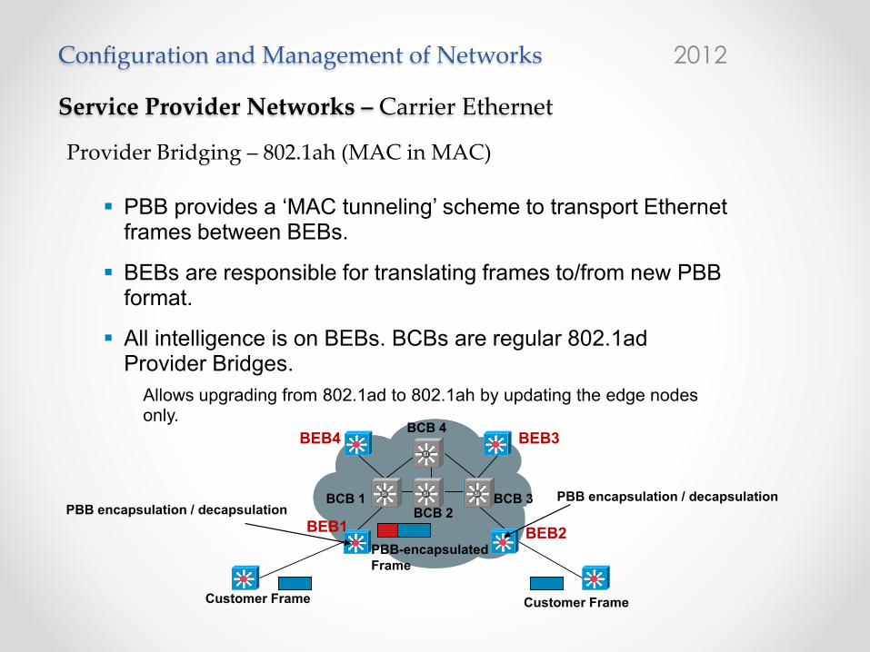
� PBB provides a ‘MAC tunneling’ scheme to transport Ethernet frames between BEBs.
� BEBs are responsible for translating frames to/from new PBBformat.
� All intelligence is on BEBs. BCBs are regular 802.1adProvider Bridges.
Allows upgrading from 802.1ad to 802.1ah by updating the edge nodes only.
BEB2BEB1
BCB 4
SiSiSiSiSiSi SiSiSiSiSiSi SiSiSiSiSiSi
SiSiSiSiSiSi
BCB 2BCB 3BCB 1
BEB3BEB4
Customer Frame Customer Frame
PBB-encapsulated Frame
PBB encapsulation / decapsulationPBB encapsulation / decapsulation

Configuration and Management of Networks 2012
Service Provider Networks – Carrier Ethernet Provider Bridging – 802.1ah (MAC in MAC)
© 2010 Cisco and/or its affiliates. All rights reserved. Cisco PublicBRKSPG-2203 9
PBB Frame Format
� Service Instance ScalabilityNew 24-bits Service Instance Identifier (I-SID) instead of 12-bits VLAN
� Domain Isolation & MAC-Address ScalabilityEncapsulate Customer MAC frames at the edge of the network into Backbone MAC frames: New MAC header
� Backwards Compatibility with IEEE 802.1adEthertype of B-VLAN is the same as 802.1ad S-VLAN (0x88a8)
PBB leverages existing L2 control plane mechanisms
PayloadC-TAGC-SAC-DAB-TAGB-SAB-DA
I-TAG: Contains 24 Bits toIdentify a Service Instance
B-TAG: same Ethertype as S-TagSecond MAC-Header
FCSS-TAGI-SID .
Overview

Configuration and Management of Networks 2012
Service Provider Networks – Carrier Ethernet Provider Bridging – 802.1ah (MAC in MAC)
© 2010 Cisco and/or its affiliates. All rights reserved. Cisco PublicBRKSPG-2203 12
Service Mapping and Bundling
� S-VLANs from access mapped or bundled into I-SIDs on BEBs.
� I-SID provides service identification in PBB network.Global in scope within a single operator’s network
� I-SIDs bundled into B-VLANs for transport over PBB core.
� B-VLAN defines transport topology in PBB network (e.g., a spanning-tree).
BCBs802.1ad
802.1ah
802.1adBEB
BEB BEB
BEB
I-SIDS-VLANB-VLAN

Configuration and Management of Networks 2012
Service Provider Networks – Carrier Ethernet Provider Bridging – 802.1ah (MAC in MAC)
© 2010 Cisco and/or its affiliates. All rights reserved. Cisco PublicBRKSPG-2203 13
Addressing and BEB Identification
� Each BEB uniquely identified by one or more unicast B-MAC addresses.
Additionally, a BEB may listen in to one or more B-MAC multicast group addresses
� B-MAC addresses guaranteed to be unique within a provider’s network & may be administered by operator.
C-MAC Address
B-MAC Address
BCBs
802.1ad
802.1ah
802.1adBEB
BEB BEB
BEB
B1
B2 B3
B4C1
C2
C3
C4
802.1QCE
802.1QCE

Configuration and Management of Networks 2012
Service Provider Networks – Carrier Ethernet Provider Bridging – 802.1ah (MAC in MAC)
© 2010 Cisco and/or its affiliates. All rights reserved. Cisco PublicBRKSPG-2203 14
MAC Address Learning
� Backbone Edge Bridge (BEB):Learn and forward based on both Customer MAC (C-MAC) and Backbone MAC (B-MAC) addresses
Build a mapping of C-MAC to B-MAC addresses
� Backbone Core Bridge (BCB):Learn and forward based on B-MAC addresses only
C-MAC Address Space
B-MAC Address Space
BCBs
802.1ad
802.1ah
802.1adBEB
BEB BEB
BEB
Configuration and Management of Networks 2012
Service Provider Networks – Carrier Ethernet Provider Bridging – 802.1ah (MAC in MAC)
© 2010 Cisco and/or its affiliates. All rights reserved. Cisco PublicBRKSPG-2203 16
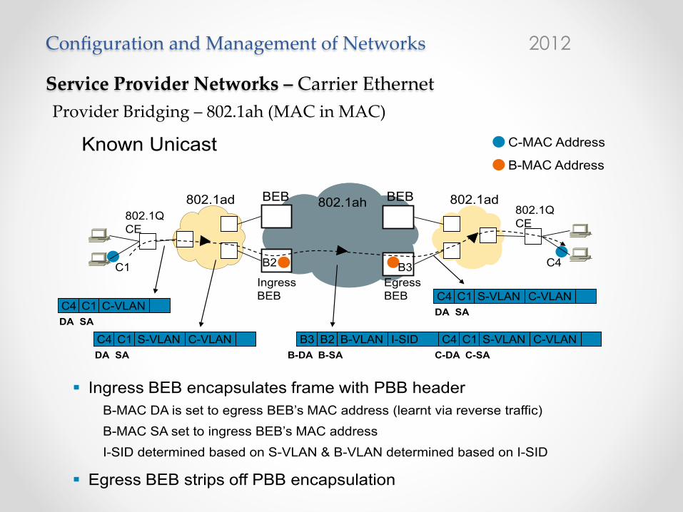
Network Packet Flow
� Ingress BEB encapsulates frame with PBB headerB-MAC DA is set to egress BEB’s MAC address (learnt via reverse traffic)
B-MAC SA set to ingress BEB’s MAC address
I-SID determined based on S-VLAN & B-VLAN determined based on I-SID
� Egress BEB strips off PBB encapsulation
C-MAC Address
B-MAC Address
802.1ad 802.1ah 802.1ad
Ingress BEB
BEB BEB
Egress BEB
B2 B3C1 C4
802.1Q CE
802.1Q CE
C4 C1 C-VLAN
C4 C1 B3 B2 C4 C1
DA SA
DA SA B-DA B-SA C-DA C-SA
S-VLAN C-VLAN S-VLAN C-VLANB-VLAN I-SID
C4 C1DA SA
S-VLAN C-VLAN
Known Unicast

Configuration and Management of Networks 2012
Service Provider Networks – Carrier Ethernet Provider Bridging – 802.1ah (MAC in MAC)
© 2010 Cisco and/or its affiliates. All rights reserved. Cisco PublicBRKSPG-2203 17
Network Packet Flow
� Ingress BEB encapsulates frame with PBB headerB-MAC DA is set to B-MAC multicast group addressB-MAC SA set to ingress BEB’s MAC addressI-SID determined based on S-VLAN & B-VLAN determined based on I-SID
� One or multiple egress BEBs listen in to the group address
C-MAC Address
B-MAC Address
802.1ad 802.1ah 802.1adBEB BEB
B2 G3C1
802.1Q CE
802.1Q CEG3G3
C4
C4 C1 C-VLAN
C4 C1 G3 B2 C4 C1DA SA
DA SA B-DA B-SA C-DA C-SA
S-VLAN C-VLAN S-VLAN C-VLANB-VLAN I-SID
C4 C1DA SA
S-VLAN C-VLANIngress BEB
Egress BEB
Multicast, Broadcast and Unknown Unicast

Configuration and Management of Networks 2012
Service Provider Networks
MPLS Three main VPN technologies: • Layer 3 VPNs • Layer 2 VPNs
• VPLS • Point-‐‑to-‐‑point PSW (pseudowires)
MPLS is already used in many different applications: – Unicast IP routing – Multicast IP routing – MPLS TE – QoS – MPLS VPNs

Configuration and Management of Networks 2012
MPLS -‐‑ Basic Idea
• Packets are switched, not routed, based on labels • Labels are filled in the packet header • Basic operation:
• Ingress LER (Label Edge Router) pushes a label in front of the IP header
• LSR (Label Switch Router) does label swapping • Egress LER removes the label
• The key : establish the forwarding table • Link state routing protocols
• Exchange network topology information for path selection • OSPF-TE, IS-IS-TE
• Signaling/Label distribution protocols: • Set up LSPs (Label Switched Path) • LDP, RSVP-TE, CR-LDP

1a. Routing protocols (e.g. OSPF-TE, IS-IS-TE) exchange reachability to destination networks
1b. Label Distribution Protocol (LDP) establishes label mappings to destination network
2. Ingress LER receives packet and “label”s packets
IP
IP 10
3. LSR forwards packets using label swapping
IP 20
4. LER at egress removes label and delivers packet
IP
Configuration and Management of Networks • 2012

Configuration and Management of Networks 2012
MPLS -‐‑ Advantages
• Scalability of network layer routing. Using labels as a means to aggregate forwarding information.
• Labels provide forwarding along an explicit path different
from the one constructed by destination-based forwarding. Better QoS and TE capabilities
• Recursion is provided for; hence tunnels can exist within tunnels. Several VPN traffic separation possibilities.

Configuration and Management of Networks 2012
Service Provider Networks
NSN JN
CIS-S
P EM
EA 19
- 23
, Nov
. 201
2
Junos MPLS and VPNs
Chapter 7–4 • VPN Review www.juniper.net
Virtual Private NetworkA VPN is a private network that is constructed over a shared, public infrastructure such as Frame Relay, an Asynchronous Transfer Mode (ATM) network, or the Internet. It is considered virtual because it does not require a separate physical network, but instead it is a logical network, one of possibly many logical networks, that uses a single physical network. It is considered a private network because a VPN can have its own separate addressing and routing scheme to interconnect devices that must communicate.
A VPN is designed so that only devices intended to communicate with each other can do so. For instance, as shown on the slide, a VPN can be the network infrastructure that provides communication between the corporate headquarters, branch offices, mobile users, data centers, suppliers, and customers, while ensuring that unwanted devices cannot gain access to this private network.

Configuration and Management of Networks 2012
Service Provider Networks
NSN JN
CIS-S
P EM
EA 19
- 23
, Nov
. 201
2
Junos MPLS and VPNs
Chapter 7–6 • VPN Review www.juniper.net
Customer Premises VPN Solutions
A customer premises equipment (CPE) VPN solution is a VPN that relies only on the customer’s
equipment to create and manage tunnels for the private IP traffic. Layer 2 Tunneling Protocol (L2TP),
Point-to-Point Tunneling Protocol (PPTP), and IP Security (IPsec) tunnel mode are protocols used by
customer premises equipment for this purpose. When the ISP receives IP packets from the
customer, they are treated as normal IP packets and are routed accordingly.
Provider-Provisioned VPN Solutions
A provider-provisioned VPN solution is a VPN that relies on the provider’s equipment to create and
manage tunnels for the private traffic using MPLS as the enabling technology. Examples of
provider-provisioned VPNs include BGP/MPLS-based VPNs, such as Layer 3 VPNs (defined in
RFC 4364), Layer 2 MPLS-based VPNs, including BGP Layer 2 VPNs (defined in draft-kompella), and
LDP Layer 2 circuits (defined in RFC 4447), as well as virtual routers and the virtual private LAN
service (VPLS) approach, which includes BGP signaled VPLS (defined in RFC 4761) and LDP signaled
VPLS (defined in RFC 4762).

Configuration and Management of Networks 2012
Service Provider Networks – Layer 3 Vs. Layer 2 VPNs
NSN JN
CIS-S
P EM
EA 19
- 23
, Nov
. 201
2
Junos MPLS and VPNs
Chapter 7–12 • VPN Review www.juniper.net
Provider-Provisioned Layer 3 VPN CharacteristicsFor Layer 3 VPNs, the provider’s routers participate in the customer’s Layer 3 routing. Thus, the customer’s routing protocol is terminated by the provider’s router. It is the responsibility of the provider’s router to manage VPN-specific routing tables and to distribute those VPN-specific routes to the customer’s remote sites.
Provider-Provisioned Layer 2 VPN CharacteristicsFor Layer 2 VPNs, as with Frame Relay, a Layer 2 VPN customer maps its Layer 3 routing to the Layer 2 circuit mesh. In this situation, the provider delivers Layer 2 circuits to the customer, one for each remote site. The provider does not participate in the routing of the customer’s private IP traffic, so the routing protocol used by the customer edge (CE) device is terminated by the remote CE device.

Configuration and Management of Networks 2012
Service Provider Networks – Layer 3 VPNs NSN
JNCIS
-SP
EMEA
19 -
23, N
ov. 2
012
Junos MPLS and VPNs
www.juniper.net VPN Review • Chapter 7–13
Outsourced VPNs
MPLS-based VPNs make it possible for a service provider to offer value-added services to new and existing customers using its existing network infrastructure.
The Junos OS supports Layer 3 provider-provisioned VPNs based on RFC 4364. In this model, the provider edge (PE) routers maintain VPN-specific routing tables called VPN route and forwarding (VRF) tables for each of their directly connected VPNs. To populate these forwarding tables, the CE routers advertise routes to the PE routers using conventional routing protocols like RIP, OSPF and EBGP.
The PE routers then advertise these routes to other PE routers with Multiprotocol Border Gateway Protocol (MP-BGP) using extended communities to differentiate traffic from different VPN sites. Traffic forwarded from one VPN site to another is tunneled across the service provider’s network using MPLS. The MPLS-based forwarding component allows support for overlapping address space and private addressing.
Configuration and Management of Networks 2012
Service Provider Networks – Layer 3 VPNs
NSN JN
CIS-S
P EM
EA 19
- 23
, Nov
. 201
2
Junos MPLS and VPNs
Chapter 7–14 • VPN Review www.juniper.net
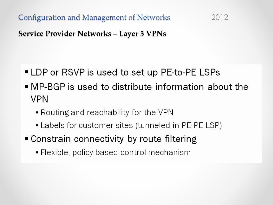
Label Distribution Protocol for LSPsSetting up and maintaining label-switched paths (LSPs) between PE routers requires a label distribution protocol. Options include the LDP or RSVP.
MP-BGP Distributes VPN InformationMP-BGP is used to distribute information about the VPNs. These communications include routing and reachability information as well as the MPLS labels that map traffic to a particular VPN forwarding table and interface.
Provider Constrains Connectivity by Route FilteringTo ensure that routing information about a particular VPN is only made available to sites participating in that VPN, the provider must constrain advertisements using routing policy (for example, route filtering).

Configuration and Management of Networks 2012
Service Provider Networks – Layer 3 VPNs Advantages:
NSN JN
CIS-S
P EM
EA 19
- 23
, Nov
. 201
2
Junos MPLS and VPNs
Chapter 7–16 • VPN Review www.juniper.net
Advantages for the Subscriber
With Layer 3 provider-provisioned VPNs, the subscriber can offload its routing responsibilities to the
provider, thus allowing the customer to focus on its core competencies.
Advantages for the Provider
The provider can offer a value-added (revenue producing) service to its customers using a scalable
IP-centric-based backbone technology.
Configuration and Management of Networks 2012
Service Provider Networks – Layer 2 VPNs:
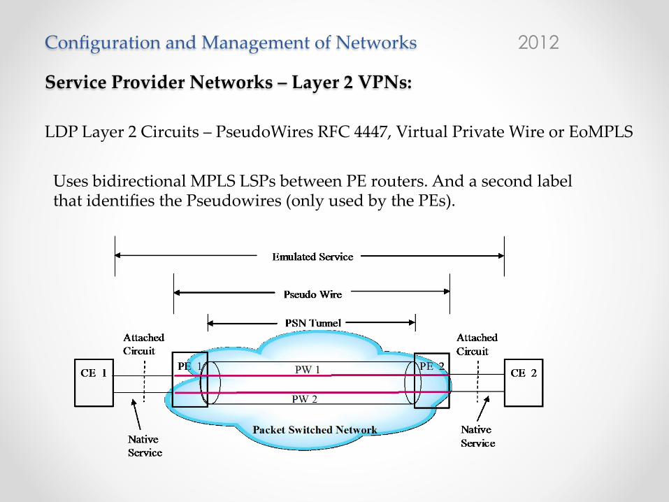
LDP Layer 2 Circuits – PseudoWires RFC 4447, Virtual Private Wire or EoMPLS
Uses bidirectional MPLS LSPs between PE routers. And a second label that identifies the Pseudowires (only used by the PEs).
EE6364
DCW MPLS-20
Pseudo-Wire Emulation End-to-End (PWE3) RFC 398510 specifies the architecture of pseudo-wire emulation end-to-end (PWE3). PWE3 is a mechanism that emulates the essential attributes of a telecommunications service (such as a TDM leased line, ATM, Frame Relay, Ethernet) over a Packet Switched Network (PSN), such as IP or MPLS network. It is intended to provide the necessary functionality to emulate the wire with the required degree of faithfulness for the given service definition. This “wire” is called pseudo wire (PW). The required functions of pseudo wires include encapsulating service-specific bit streams, cells, or PDUs arriving at an ingress port, carrying them across an IP path or MPLS tunnel, and decapsulating service-specific bit streams, cells, or PDUs and transmitting them to the customer. In some cases it is necessary to perform other operations such as managing their timing and order, to emulate the behavior and characteristics of the service to the required degree of faithfulness. The network reference model of PWE3 is shown in the following figure. 10 S. Bryant, Ed., P. Pate, Ed., “Pseudo Wire Emulation Edge-to-Edge (PWE3)
Architecture,” RFC 3950, March 2005.

Configuration and Management of Networks 2012
Service Provider Networks – Layer 2 VPNs: VPLS NSN
JNCIS
-SP
EMEA
19 -
23, N
ov. 2
012
Junos MPLS and VPNs
www.juniper.net VPN Review • Chapter 7–23
Provider’s Network Appear to Be a Single LAN SegmentA newer service that can be provided to the customer is VPLS. To the customer, VPLS appears to be a single LAN segment. In fact, it appears to act similarly to a learning bridge. That is, when the destination media access control (MAC) address is not known, an Ethernet frame is sent to all remote sites. If the destination MAC address is known, it is sent directly to the site that owns it. The Junos OS supports two variations of VPLS, BGP signaled VPLS and LDP signaled VPLS. VPLS is covered in more detail in later chapters.
No Need to Map Local Circuit to Remote SitesIn VPLS, PE devices learn MAC addresses from the frames that it receives. They use the source and destination addresses to dynamically create a forwarding table (vpn-name.vpls) for Ethernet frames. Based on this table, frames are forwarded out of directly connected interfaces or over an MPLS LSP across the provider core. This behavior allows an administrator to not have to manually map Layer 2 circuits to remote sites.
Configuration and Management of Networks 2012
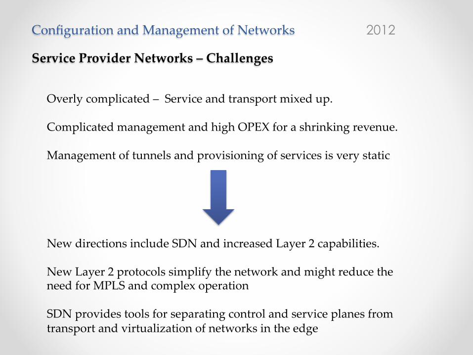
Service Provider Networks – Challenges
Overly complicated – Service and transport mixed up. Complicated management and high OPEX for a shrinking revenue. Management of tunnels and provisioning of services is very static
New directions include SDN and increased Layer 2 capabilities. New Layer 2 protocols simplify the network and might reduce the need for MPLS and complex operation SDN provides tools for separating control and service planes from transport and virtualization of networks in the edge