Embed Size (px)
Citation preview

1
Connect and Protect. Coupler and Front End Systems

2
1
1 Karl Scharfenberg.
Systematic SafetyQuality and safety – these are the attributes associated with Voith for more than a century: In 1903, Karl Scharfenberg put his first vision of an automatic train coupler into practice.
Continuous technical refinements and updated technology have made the “Schaku” one of the most prominent rail-way coupler systems all over the world. More than 500,000 couplers in use to date, from light rail vehicles to high speed trains, show the high degree of trust the customers have in Scharfenberg products.
Today, Voith system solutions cover the whole range of energy absorbing components for train front ends, including kinemat-ics and control electronics. Be it light rail, monorail or metro vehicles, regional transport or high speed trains, Voith offers the best solution for every application. In close cooperation with our customers, we adapt our products to any given purpose and situation, always keeping an eye on the safety of passengers and train.
One of the First Scharfenberg Couplers

3
Major Mile Stones on the Scharfenberg Track Record
1903 Development of the first automatic Schaku by Karl Scharfenberg; German Reichspatent
1921 Foundation of the incorporated company “Scharfenberg Aktiengesellschaft“ in Berlin
1925 Introduction of the “Schaku” at the rapid transit railway “Berliner S-Bahn” and the “Hamburger Hochbahn”
1957 The “Scharfenberg GmbH” becomes part of the Salzgitter group of companies
1998 Foundation of the “Voith Turbo Scharfenberg GmbH & Co. KG”
2002 System supplier for complete train front ends, including complete front end systems; joints; system for automatically coupling AAR type couplers including electric head and air pipe connections. The type 10 Scharfenberg coupler is declared standard coupler for high speed trains
2006 Modular coupler head One4; energy absorbing joints; modular adapter coupler
2008 New data transmission concepts; start of the GFRP production on the Salzgitter site
2010 Fibre composite vehicle head Galea as new energy absorption concept; CFRP adapter coupler; new crash buffers
2012 Expansion of the Galea concept as test bed for innovative technologies
2014 GFRP energy absorber; SA3 coupler featuring automatic air pipe connections, automatic uncouple device and energy absorbing components
2016 First order for GFRP energy absorbers
Modular Concept of Modern Schakus Front End Systems and Energy Absorption Concepts

4
On our Systems, Safety Always Gets a Free Ride. From Front End Systems to Joints: Energy Absorbing Components

5
Front End Systems
P. 14 AAR Crash Energy ManagementP. 22 GFRP Energy Absorbers
Intermediate Connections between Wagons
P. 20 Semi-Permanent CouplersP. 21 Joints
Automatic Front Couplers
P. 6 Automatic Coupler TypesP. 12 Couplers of other Makes P. 16 Freight Train SystemsP. 24 Modular DesignP. 26 Coupler HeadP. 28 Data Transmission ConceptsP. 30 Energy Absorption
(Coupler Shank)P. 32 Drawgear Articulation

6
1 2
The type 10 Scharfenberg coupler excels in strength and rigid-ity and possesses a particularly wide horizontal and vertical gathering range. In 2002, it was declared standard coupler for high speed applications and is now an inherent part of the TSI (Technical Specification for Interoperability).
This coupler can be found in nearly all state railways and a multitude of high speed trains world-wide, e.g. in Germany (ICE), France (TGV), Spain (AVE trains) or China (CRH series).
Power-Pack for Standard Gauge and High Speed Applications – Type 10
Type 10 Technical Characteristics
• Strength: Compression: 1 500 kN (up to 2 000 kN) Tension: 1 000 kN
• Compliant with the UIC standard for standard gauge motor train units• Two-position coupler lock Type 10 Automatic Scharfenberg Coupler Featuring Side-Mounted
Electric Heads, Centring Device and Downstream Deformation Tube
Automatic Scharfenberg Coupler
Automatic Scharfenberg couplers are mainly found at the train ends. Allowing automatic and safe coupling / uncou-pling, they permit a flexible train set configuration on the track. Different coupler types are available, depending on the application and required forces.

7
3 4
1 Flirt 3, Abellio Rail NRW, Germany.
2 Desiro RUS, Sovjet Union.
3 Calgary C-Train, Canada.
4 Hanover Stadtbahn (light rail), Germany.
Popular High-Performer for Metro and Electric Vehicles – Type 35The type 35 coupler is mainly used for metro vehicles and it is also suitable for electric vehicles. It can be found e.g. in Shanghai, Singapore, Salt Lake City and Edmonton (Canada).
Type 35 Automatic Scharfenberg Coupler Featuring Electric Heads and Centring Device
Type 35 Technical Characteristics
• Strength: Compression: up to 1 250 kN Tension: up to 850 kN
• Guiding horn for increased gathering range• Two-position coupler lock
8
1 2
The type 330 is mainly found in light rail and light metro vehicles. Despite its small dimensions it offers remarkable strength and the possibility to use bottom-mounted electric heads. It features a wide gathering range, even without a guid-ing horn. Designed as foldable or retractable coupler, it can be hidden behind closed front hatches. The extremely narrow dimensions of the tramtrain Avanto in Paris even called for a coupler that folds twice along its longitudinal axis.
Versatile for Light Rail and Monorail Vehicles – Type 330
Type 330 Technical Characteristics
• Strength: Compression: 800 kN Tension: 600 kN
• Particularly wide gathering range without guiding horn
Type 330 Automatic Scharfenberg Coupler Featuring Bottom-Mounted Electric Head and Rubber Cushion Drawgear

9
3 4
1 Riyadh metro, Saudi-Arabia
2 Shenyang tram, China.
3 Berlin tram (type 430 coupler), Germany.
4 Leipzig tram (type 530 coupler), Germany.
Its compact and lightweight design makes the types 430 and 530 ideal couplers for low-floor urban railways, monorails and people movers. Designed as foldable couplers, they can be combined with front hatches. Type 430 couplers can be found in Berlin (Berliner Straßenbahn), Kuala Lumpur (KL Rapid) or the monorails of Sao Paulo and King Abdullah Financial Dis-trict. The type 530 was mainly developed for the Eastern Ger-man market and is compatible to the TGL couplers that used to be very common there.
Light-Weight Design for Urban Railways – Type 430 and Type 530
Type 430 Automatic Scharfenberg Coupler Featuring Integrated Electric Heads and Rubber Cushion Drawgear with Support
Type 430 / 530 Technical Characteristics
• Strength: Compression / tension: 300 kN
• Small dimensions, low weight• Compact design without guiding horn

10
The Tough One –Type 55
For Shunting and Unimog CouplersThis coupler – developed in compliance with the UIC directive for drawhooks – provides safety and rationalisation in shunting operations. The type 55 coupler allows automatic coupling and uncoupling with a drawhook, no longer requiring any shunting staff.
The robust and service friendly coupler significantly reduces wear and maintenance – perfect for rough operating conditions.
This type of coupler can also be fitted with any other Scharfenberg couper head.
Type 55 Automatic Scharfenberg Coupler
Couplers for industrial applications need to be extremely robust and wear resistant, just like type 55 Scharfenberg couplers. Especially in shunting operations or automated marshalling of trains equipped with drawhooks, these couplers make the industrial working environment considerably safer.

11
For Shunting or Towing –Adapter CouplersAdapter couplers are used whenever different coupler types need to be connected or the coupling height is not compatible. During standard train operation this should not occur, but it is common practice in shunting or towing operations.
Modular Adapter CouplerTraditional adapter couplers were mostly very special in de-sign and layout, as they had to be adapted to one particular combination of coupler heads as well as a particular difference in coupling height.
This new modular approach separates the individual parts, namely the two coupler heads and the intermediate adapter piece bridging the offset in height. Should no adapter piece be required, the coupler heads can just as well be directly con-nected. This way, adapter couplers of any combination can be individually and flexibly assembled.
What is more, the individual components are mounted on the train one after the other, so that only a fraction of the weight needs to be carried at a time.
CFRP Adapter: High-Tech TowingAdapter couplers are only needed for towing or shunting trains. This means, they need to be fitted by the operating staff on track manually. An ideal adapter coupler would be lightweight and yet able to bear the heavy load of a whole train.
For common steel couplers used to date, the possibilities for weight reduction are virtually exhausted. This new type of adapter coupler mainly consists of carbon fibre reinforced plastics, a hightech material often to be found in aviation technology. Its weight of only 23 kg allows the CFRP adapter coupler to be fitted on the train by one person alone.
Modular Adapter Coupler with and without Intermediate Adapter Piece, Sample Configuration
CFRP Adapter Coupler

12
More than 100 years of experience have made us experts in energy absorption and couplers, including those of other makes. Depending on customer requirements, the diverse coupler heads are adapted and combined with proven Scharfenberg energy absorbing components. This way, every application gets its optimal solution.
Looking Beyond Our Own Horizon.Couplers of Other Makes
AAR Type CouplerAAR type couplers are in common use on railcars on the American market and suited for heavy loads. The mechanical connection between the couplers is established automatically, whereas the large coupler head play usually does not allow any pneumatic or electric connection. These, however, can be integrated into an additional support system. For further infor-mation, refer to page 14.
Tomlinson Type CouplerTomlinson couplers are also mainly used on the American market. Voith has developed a proto-type combining their proven energy absorption systems with the Tomlinson coupling principle, allowing mechanical, electric and pneu-matic connections to be established automatically.
AAR Coupler Tomlinson Coupler

13
Voith SA3 TypeSA3 couplers are semi-automatic centre buffer couplers. They are widely used in the widely used in Russia, Scandinavia, as well as in the Baltic and Eastern European States.For further information on SA3, refer to page 17ff.
Voith SA3 Coupler
Wedgelock Type CouplerThe Wedgelock principle can be mainly found on British trains and also allows automatic coupling. Here, the coupler lock members are held in place by pneumatically operated wedges.
GF (Fischer) Type CouplerThe GF type automatic coupler is widespread in Belgium and Switzerland. During automatic coupling, the cone and funnel shaped coupler heads interlock. The couplers can be provided with air pipe connections and electric heads.
GF Type CouplerWedgelock Coupler

14
1 SMART, California, featuring CEM (Crash Energy Management).
AAR Crash Energy ManagementOn a global scale, rail-bound traffic faces an increase in safety and crash worthiness requirements. This also applies to AAR couplers, which origi-nally were not equipped with energy absorption features of their own. Voith has developped technologies which optimally complement the high strength of the AAR coupler head with energy absorbing components. Today, a complete CEM (Crash Energy Management) system is available, complying with the latest FRA and PRIIA 305 safety regulations.
CEM-SystemA Crash Energy Management system is composed of several matched energy absorbing components which are integrated in both the coupler and the carbody. The energy absorption works in a cascading way, compensating a high amount of energy in case of a crash and preventing an overriding of the cars.
Working Principle: CouplerA standard AAR coupler head was fitted with state-of-the-art energy absorption features, forming a “push back” coupler. The drawgear is mounting compatible to that of standard AAR couplers. In addition to the usual reversible energy absorption element it contains an irreversible part based on deformation tube technology. Should a crash occur, the coupler is pushed back into the drawgear, absorbing a great amount of energy on its way.
Constituent Parts of the System
• “Push back” AAR coupler including support• Anti-climber• Lateral energy absorbers
Crash Energy Management System (SMART Project) Push Back Coupler

15
1
Anti-ClimberAt a certain point during the push-back process, the anti- climber brackets interlock and thus prevent any vertical move-ment of the cars.
A separate support structure mounted sideways of the coup-ler ensures that the energy absorption takes place in a con-trolled manner. One part of this support carries the anti-climb-er, another supports the coupler, the latter pivoting out of the way as soon as the push-back process starts.
Lateral Energy AbsorbersTwo lateral energy absorbers have been integrated into the carbody structure above the coupler level. At their front ends, they are connected through the anti-climber. This way, addi-tional energy will be absorbed as the crash proceeds.
Anti-Climber Lateral Energy Absorber

16
Freight applications are characterised high strength requirements and rough conditions. Bulk material in particular may cause tenacious soiling. What is needed here is a simple and robust coupler, one that requires hardly any maintenance even in rough environment. A further aspect is energy absorption. For 2017, an update of the DIN EN 15227 – defining crash worthiness requirements – is planned, which for the first time will include locomotives. Our developments offer maintenance-friendly design tailored to individual customer requirements. Along with that we provide technical support such as strength calculations and energy absorption certificates.
More Power – Freight Train Systems
Energy absorption for all types of coupler headsThe modular design of our components allows us to provide couplers with optimal energy absorption, no matter which coupler head interface. Solutions for different mounting spaces are available.
Exemplary energy absorption solution comprising reversible and irreversible parts.

17
Voith SA3 TypeApart from AAR* couplers, SA3 couplers can be seen as the mother of all freight couplers. SA3 coupler heads are extreme-ly robust and designed for heavy load applications, like those in coals or iron ore transportation. Voith has developed an advanced, modular type of SA3 coupler head.
Integrated air pipe connections, electric heads or sensors allow a higher degree of automation, which makes these solutions particularly appealing for locomotives. For further information, refer to the next page.
Possible AAR type coupler for freight applications
SA3 coupler head (long version) featuring mixed coupler device, support and draft gear.
* AAR-type coupler heads can also be complemented with Voith energy absorption solutions

18
Voith Standard SA3 Coupler Head featuring Mixed Coupler Device
SA3 coupler heads are extremely robust and designed for heavy load applications, like those in coal or iron ore transportation. As semi-auto-matic center buffer couplers they are widely used in the former Soviet states. In a modular approach, Voith combines an advanced SA3 coupler head with different types of energy absorption in the draft gear.
A Strong Combination –SA3 Coupler
Coupler HeadThe coupler head comes in two variations, a long version with shank and a Voith standard version featuring a muff coupling collar. The latter one can be combined with any type of Voith energy absorption solution in the draft gear.
The coupler head contour corresponds to that of the Russian SA3 coupler, including standard locking members.
The coupler head was modified in a way that an integration of different types of mixed coupler devices is possible.
Voith Standard SA3 Coupler Head Featuring Muff Coupling Collar

19
Automatic Air Pipe Connection
Energy AbsorptionEnergy absorption solutions cover the increased requirements of new safety standards. Depending on the re quirements, different types of energy absorption, both reversible and irre-versible, are available, plus combinations of these two.
Reversible energy absorption is covered by maintenance-free polymeric springs in different load dimensions. For irreversible energy absorption, different types of deformation tubes are provided.
Draft Gear with Flange Connection with Reversible and Irreversible Energy Absorption
Draft Gear with Yoke with Reversible Energy Absorption
Air Pipe Connection / Automatic UncouplingAdditional guiding elements prevent the vertical clearance in the coupler head, allowing for an automatic connection of air pipes and direct coupling with AK69e / Intermat coupler heads. A pneumatic uncouple device makes automatic uncoupling possible.
Integrated Electric Head / Elektro-pneumatic BrakingThe integration of an electric head offers many advantages: It provides the power supply and the interfaces for any data transmission and forms the basis for sensor and monitoring systems. The coupling states may be monitored this way, for instance.Furthermore, electric connections allow electro-pneumatic braking of the train, meaning a synchronised braking of all cars.

20
Semi-Permanent Coupler with Anticlimbing Feature
Working PrincipleDuring a train crash or heavy impact, the longitudinal forces are converted into vertical swerving movements leading to an overriding of the cars once a critical momentum has been ex-ceeded. This may cause the wagon to disconnect from its Jacobs bogie and damage softer structures.
The anti-climbing feature has been designed to prevent this overriding right from the start. To do so, it uses a simple, yet highly effective principle: The rear end of the coupler shank features a special geometry.
As soon as the reversible stroke of the coupler has been uti-lised, this geometry interlocks with the bearing bracket, build-ing a counter-momentum that holds the wagons down.
Additional energy absorbing components of the semi-per-menant coupler, e.g. deformation tubes or hydrostatic damp-ers, convert kinetic energy and help to keep the load on a controllable level.
Operating Principle of the Anticlimbing Feature
Semi-permanent couplers establish a safe and reliable permanent con-nection between intermediate cars. For the first time, a semi-permanent coupler for metro vehicles assumes anti-climbing function. Contrary to conventional systems, this coupler has a stabilising effect – without addi-tional space requirements – before any climbing occurs.
Optimum safety requires a perfect interaction of all the connecting components in a trainset. In case of an impact, the automatic couplers and further energy absorbing com-ponents of the train front end work hand in hand with the semi-permanent couplers and joints connecting the wag-ons. Operating in a cascading way, they function as one matched energy absorption system.
solid contact
crashF
crashF
crashF
solid contact

21
Joints
Basic DesignBasically, joints consist of two parts which are connected: joint fork and joint eye with spherical bearing. The spherical bearing allows cardanic movements and cushions impacts.
Contrary to standard semi-permanent couplers, joints also compensate vertical loads. A torsion bar suspension mounted between the cars brings additional stability.
Energy AbsorptionShould additional energy absorption be needed (e.g. for heavy rail applications), joints may be fitted with energy absorbing elements. Our standard energy absorbing joint can be pro-vided with deformation tubes on both ends – a proven tech-nology which can be exactly matched with your requirements. A combination of both energy absorbing joints and non ener-gy absorbing joints is also possible.
Whenever trains are equipped with Jacobs bogies, joints are used as inter-mediate connections between the cars. They transmit driving forces between the car bodies, harmonise deflection angles and cushion impacts. Joints always have a connection with the Jacobs bogie.
Energy Absorbing Joint with Deformation Tube (Partly Sectional View)

22
DesignKey element of the light-weight energy absorber is a fibre composite tube functioning as crash element. Its rear end is integrated into a bearing connecting the absorber to the vehicle.
The latter also functions as guiding element and nozzle. The front end holds an anti-climber plate which, in case of a collision, prevents the vehicles from climbing. Both bearing and anti-climber are made of aluminium.
FunctionIn case of a collision, the fibre composite tube is pressed through the nozzle. This induces a controlled collapse of the laminate. The laminate defibrates on its way, which makes it easy to deflect downwards. This reduces the space required behind the absorber.
The load characteristics can be adapted to customer requirements, a multiple force level layout is possible, as well as increasing force level characteristics.
Energy absorbers serve to transform the crash energy generated during an impact and thus allow the best possible protection for both passen-gers and rolling stock. GFRP energy absorbers are characterised by a low total weight and a constant energy absorption behaviour. This results in a high energy aborption capacity and a remarkable energy to weight ratio. With approximately 90 kg, their weight is far below that of standard steel absorbers.
Low Weight, High Performance – GFRP Energy Absorber
GFRP Energy Absorber GFRP Energy Absorber, Design Variation

23
Deflection plate
Range of stroke / force layoutDeflection of laminate after an impact
F [kN]
Hub: 100 … 1 0000
1 600
800
Technical data / layout
Crash stroke 100 – 1 000 mm
Force levels 600 – 1 600 kN (± 10 %)
Energy dissipation bis 1,6 MJ
Displacement acc. to EN 15227 bis 80 mm
Operating temperature -40 bis +60 °C
Fire protection EN 45545-2:2013 HL3; R7
Weight (nominal) 50 – 95 kg
Benefits
+ low total weight + constant energy absorption behaviour + above average weight-specific energy absorption capacity + variable design and force layout + multi-level force layout possible + minimum corrosion through the use of aluminium and glasfibre reinforced plastics
s [mm]

24
Modularity: Everthing’s PossibleApart from reliability and safety aspects, flexibility and adaptability are the main requirements a train coupler has to comply with. The modular design of the Scharfenberg couplers and different coupler types allow us to provide the optimum coupler for each and every application and condition.
P. 26 Coupler Head
P. 28 Data and Signal Transmission

25
P. 30 Coupler Shank / Energy Absorption Systems P. 32 Drawgear Articulation

26
The Coupler’s Centrepiece – Coupler HeadAn automatic coupler’s key functionalities are resumed by the coupler head. The connection of two couplers – mechanically, pneumatically and electrically – can only be established through the coupler head and its locking mechanism.
The Special DesignThe cone and funnel shape of the coupler face establishes a rigid and slack-free connection, reducing coupler play to a minimum. Coupler head extensions and a guiding horn assure the maximum possible gathering range. This way, automatic coupling is possible even under horizontal, vertical or angular offset, as for example in curves or on hilltops.
Coupler Lock: Safe and Wear-ResistantThe coupler lock is the functional heart of every automatic Schaku. It mainly consists of a pivot-mounted hooked plate, a coupling link and tension springs. During coupling, the coupling links and hooked plates of the two couplers interlock, forming an equilibrium of forces. A very simple, but efficient mecha-nism that excels in wear-resistance and safety, even under ex-treme conditions.
Locking Device (only for two-position coupler locks)
Central Pivot
Tension Spring
Coupling Link Hooked Plate
Coupler Lock Components (Two-Position Coupler Lock)

27
Modularity at Peak Level – One4The One4 coupler head concept is a logical consequence of our modular way of thinking. Coupler head and coupler body were separated, the coupler body designed as a “one size fits it all” piece to be fitted with the individual, type specific front plate. This can be easily replaced and yet remains compatible to existing couplers.
Enjoy MaintenanceThe One4 offers a number of benefits, especially for repair and maintenance. When the coupler front plate is removed, the coupler lock components are easily accessible and can be replaced without any special tools.
Furthermore, a standardised electric head operating gear and heating concept considerably save repair time and effort.
One4 Coupler Head: Completely Modular Concept with Removable Front Plate and Standardised Electric Head Operating Gear
One4 with Removed Front Plate
Standardised Electric Head Operating Gear Support (for Lateral Electric Heads)
Heating Elements

28
Electric Heads and Coupler / Front Hatch Control UnitsApart from power transmission, electric heads are used for transmitting control signals as well as data and video signals. They are mounted on the coupler head and, when uncoupled, are protected from the ingress of dirt and water by means of electric head covers. Our micro-processor based coupler and front hatch control units offer standard plug-and-play interfaces for controlling and diagnosing the interaction of automatic couplers and front hatch systems.
Electric Head Casing ModelsStandardised electric head casing models and interfaces en-sure easy installation and a perfect interaction of all components.
Depending on the number of contacts required and on the position of the electric head with relation to the mechanical head, different casing types are available: two for lateral arrangement, and one for top or bottom mounted electric heads. A standard electric head includes a contact block fit-ted with contacts, cables and a hand plug. The contacts are easily replaceable from the front, the hand plug ensures an easy-to-fit connection to the carbody.
Coupler and Front Hatch ControlPerfect interaction is also required for coordinated coupler and front hatch movements. Our control unit operates all ac-tuators of this system and provides an easy-to-use control and diagnosis interface to the vehicle. Diagnosis comprises only few signals, keeping the cabling manageable and still considerably reducing requirements for diagnosis on the vehicle side.
The robust coupler and front hatch control unit can be mount-ed either on the car underframe or in the front nose. A data bus connection to the vehicle is optional, and both service and maintenance software are available for maintenance purposes.
The Three Standard Electric Head Casing Models Coupler and Front Hatch Control Unit, Cover Removed

29
Without Electric Head: RadiConn and GigaPlugRadiConn is a contact-free data transmission concept which is particularly resistant to soiling, keeping the failure rate – and related maintenance works – at a minimum. The system uses near-field radio coupler pins. These may be integrated into the electric head, but can just als well be mounted anywhere on the mechanical coupler head. This makes the RadiConn particularly interesting for retrofit applications.
GigaPlug, an advancement of RadiConn and capable of contact-free realtime connections, provides a full duplex data transfer rate of 1 Gbit/s.
Cost-Effective Retrofit Solution: TLMThe Train Line Modem (TLM) shares the contacts and lines of an already configured electric head using a special modula-tion technique. This way, control and operating signals as well as train information, video or CCTV data may be transmitted without any modification on the coupler. A cost- effective solution for trains already in operation.
For New Vehicles: QuatConn and OctiConnQuatConn is a solution comprising 4-pole pin and socket connectors which need to be integrated into an electric head. Once a contact block has been prepared to hold the contacts, these are mounted just like the standard ones. This makes the QuatConn a preferred solution for new vehicles.
The OctiConn connectors work along the line of the QuatConn, but they offer a higher data transmission rate of 1 Gbit/s.
RadiConn (left) and GigaPlug OctiConn
Performance Enhancement Made EasySo far performance enhancements for signal and data transmission through the coupler meant considerable effort and high expenses, particularly for retrofit solutions. Voith has deve loped Fast Ethernet based systems for different applications, covering both new vehicles and upgrades of trains already in operation.
30
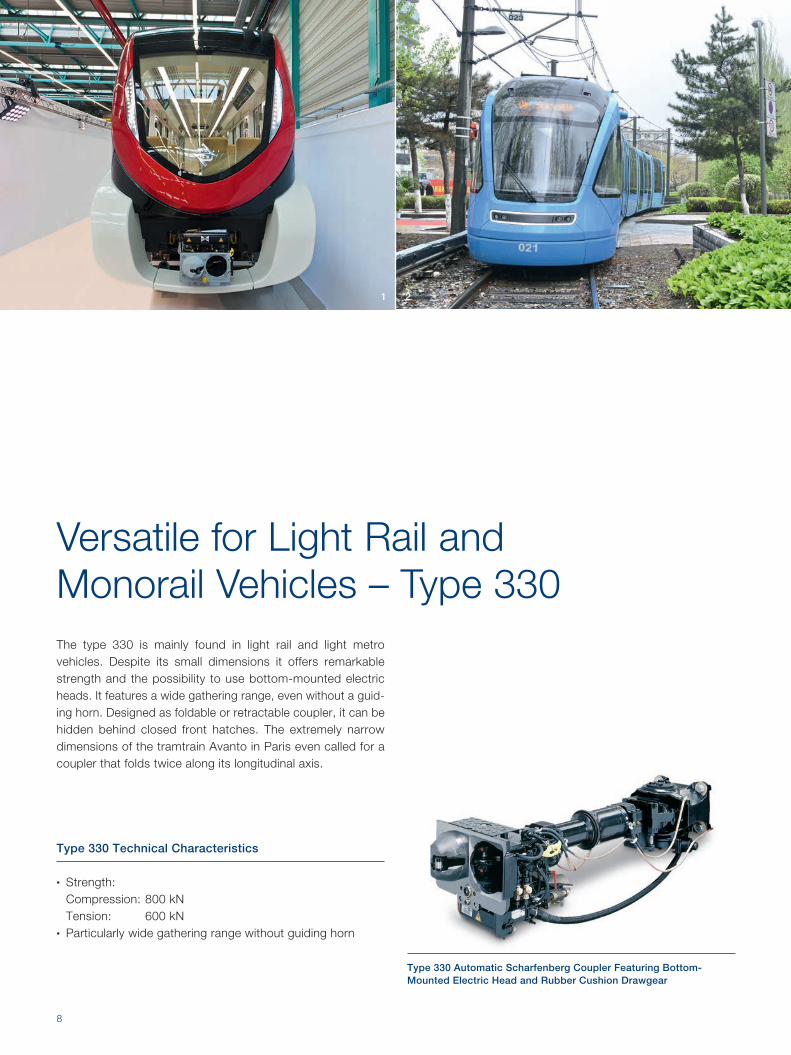
Deformation TubeThe deformation tube converts impact load into deformation. Its energy absorption characteristics allow the deformation tube to compensate major impacts. However, it will be de-stroyed while doing so.
Energy Absorption for More Safety –Coupler ShankThe coupler shank plays a major role in train safety. Customised to fit its individual purpose and application, it integrates the coupler’s energy absorption features. Reversible energy absorbing components like dampers smoothen train operation and compensate minor impacts. Irreversible (destructive) energy absorbing components like deformation tubes, on the other hand, can cope with major impacts. All energy ab-sorbing features in a train set are meticulously matched in a cascading way to ensure a most efficient interaction.
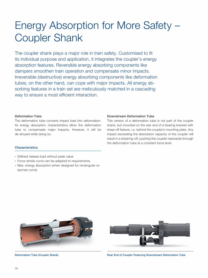
Downstream Deformation TubeThis version of a deformation tube is not part of the coupler shank, but mounted on the rear end of a bearing bracket with shear-off feature, i.e. behind the coupler’s mounting plate. Any impact exceeding the absorption capacity of the coupler will result in a shearing-off, pushing the coupler rearwards through the deformation tube at a constant force level.
Deformation Tube (Coupler Shank) Rear End of Coupler Featuring Downstream Deformation Tube
Characteristics
• Defined release load without peak value• Force stroke curve can be adapted to requirements• Max. energy absorption (when designed for rectangular re-
sponse curve)

31
Gas-Hydraulic DamperIn combination with a friction spring, the gas-hydraulic damper converts both compressive and tensile load in a regenerative way. They can be designed such that they function as “regen-erative deformation tubes”: In case of excessive load an internal bypass will be opened at a defined load level.
Hydrostatic DamperThe hydrostatic damper converts compressive load in a regenerative way.
Gas-Hydraulic Damper Hydrostatic Damper
Characteristics
• Speed-related response curve• Pre-loaded system in both directions,
tension and compression• Usually combined with spherical bearing
Characteristics
• Straight proportional response curve• Pre-loaded system in direction of compression• Usually combined with rubber cushion drawgear

32
Rubber Cushion Drawgear with and without Shear-off FeatureThe rubber cushion drawgear is a bearing bracket with inte-grated cushioning unit. Comprising either two or three rubber elements, the rubber cushion drawgear compensates both tensile and compressive loads and can be individually adapt-ed to its purpose.
Additionally, it can feature a shear-off solution. If the maximum load is exceeded, the screws fixing the cushioning unit shear off, and the whole coupler pushes rearwards under the car-body in a controlled way.
Coupler Meets Carbody –Drawgear ArticulationThe drawgear articulation establishes the connection to the carbody. Elastic components allow cardanic coupler moves and cushion minor impacts. Depending on its purpose and application, the drawgear articulation can be fitted with additional energy absorbing components to compensate tensile and compressive loads.
Rubber Cushion Drawgear with Shear-off Feature under Excessive Load
Working Mode of the Rubber Cusion Drawgear: Neutral Position Rubber Cusion Drawgear under Compressive Load

33
Bearing BracketThe bearing bracket represents the most straight-forward type of drawgear articulation: It is combined with a coupler shank featuring a spherical bearing to allow cardanic coupler moves. Just like the rubber cushion drawgear, the bearing bracket can feature an internal shear-off solution as overload protection.
If further energy absorption is required, the bearing bracket can be fitted with a rear-mounted (downstream) deformation tube with defined response characteristics. Any impact ex-ceeding the absorption capacity of the coupler will result in a shearing-off, pushing the coupler rearwards through the de-formation tube at a constant force level.
Rubber Ring / Rubber Cushion Articulation The rubber ring articulation is best suited for a narrow train front offering only small mounting dimensions. Being located on both sides – in front of and behind – the coupler mounting plate, the rubber rings cushion impacts in the direction of both compression and tension. They possess a softly rising force stroke curve and thus increase travelling comfort.
Based on the rubber ring principle, the rubber cushion articulation features rectangular rubber elements. They func-tion as anti-rotation device, while at the same time allowing a high degree of cardanic moves.
These drawgear articulations can also be designed as over-load protection solutions.
Bearing Bracket with Downstream Deformation Tube, Centring Device and Support
Rubber Cushion Articulation
Rubber Cushion Drawgear under Tensile Load
Benefits
+ High cushioning effect through shear stress of the rubber elements
+ Low-wear and maintenance-friendly design + Small dimensions + Different sizes for various applications

34
CRH 380 B / BL, China.
CRH3-380
Meanwhile, a whole family of CRH3 products has seen the light of day at the Salzgitter production site. They all have one thing in common: a huge delivery volume.
Both the design process of the CRH3-380 front nose and the manufacturing of the first systems took place at the Salz- gitter site. The remaining front noses are manufactured locally by Chinese partners. Finally, they are mounted and adjusted at the Voith site in Shanghai.
Preceding the localisation in China, our Chinese partners under-went comprehensive training in laminating the GFRP parts, as-sembling the front noses and adjusting the front hatches. When production in China started, experts accompanied the process for several weeks. The result: 100 % localised front noses at 100 % quality and functionality.
Components Supplied by Voith
Our Contribution
• Front nose module including front hatches• Front hatch kinematics (manual and automatic)• Type 10 automatic coupler• Semi-permanent couplers• Modular adapter coupler type 10 /AAR

35
EMU800, Taiwan.
EMU800
During the last years, Taiwan has invested largely to improve its rail infrastructure. Apart from a new high speed line, a fo-cus was put on intra-urban transport in and around larger cit-ies like Taipei or Kaohsiung.
Designed for a maximum speed of 130 km/h, the EMU800 vehicles are destined as commuter trains to improve the transport capacity between large urban areas.
The yellow line around the front made railway enthusiasts nickname the EMU800 "Smiling Express".
Components Supplied by Voith
Our Contribution
• Front hatches including kinematics• AAR type automatic coupler• Semi-permanent couplers• Modular adapter coupler type AAR/ semi-permanent cou-
pler

36
ICE4, Germany.
ICE4
Superlatives in rapid succession: From 2016 on, up to 300 ICE4 trains will gradually replace the Intercity/Eurocity trains presently in operation, followed by the ICE1 and ICE2 trains. Thus the ICE4 forms the new backbone of the future DB (Ger-man Railways) main line traffic. The ICx sets new standards in flexibility and operational availability and can be perfectly adapted to different transport tasks.
An advanced aerodynamic design and optimised usable floor space result in weight and energy savings, while still providing all the comfort needed for long distance travels.
The modular design and few connection points of the front nose allow for fast mounting and easy adjustment of the com-ponents. Low-maintenance encapsulated actuators remain perfectly functional even under rough operating conditions. Apart from smooth operation, these actuators prevent any un-wanted closing of the front hatches. This provides additional safety for maintenance works.
Components Supplied by Voith
Our Contribution
• GFRP driver’s cabin• Front nose module including front hatches• Front hatch kinematics (manual and automatic)• Snow deflector• Type 10 automatic coupler• Semi-permanent couplers• Adapter coupler type 10 / UIC drawhook

37
EC250, Swtzerland.
EC250
Our Contribution
• GFRP driver's cabin• Front nose module including front hatches• Front hatch kinematics• Coupler and front hatch control unit• Type 10 automatic coupler• Adapter coupler type 10/UIC drawhook
Components Supplied by Voith
Experiencing the Gotthard base tunnel at high speed: The Swiss Federal Railways (SBB) has ordered 29 eleven-car trains from Stadler Rail. They will be operated as comfortable passenger trains crossing the Alps. In the first instance, rail-way service will be realised between Zurich and Mailand, in a later stage an extension to Frankfurt is planned.
When passing the Gotthard base tunnel in winter, spontane-ous differences in temperature of up to 50 °C are possible.
The EC250, in Switzerland also knows as "Giruno" (Buzzard), is an advanced development of the FLIRT concept, reaching a maximum speed of 250 km/h. Furthermore, it has been adapt-ed to the specific safety requirements for passing tunnels.
The front hatch kinematics – patented by Voith – ensure safe and reliable operation of the front hatches, taking into account the additional energy absorption elements integrated into the train front.

G 1
712
en,
BD
/ B
AI ,
2 00
0, 2
016-
09.
Sub
ject
to
mod
ifica
tions
. A
ll d
ata
are
for
des
crip
tive
pur
pos
es o
nly
and
do
not
rep
rese
nt g
uara
ntee
d p
rop
ertie
s.
Voith Turbo GmbH & Co. KGGottfried-Linke-Str. 20538239 Salzgitter, GermanyTel +49 5341 21-02Fax +49 5341 [email protected]