Embed Size (px)
Citation preview

1
Connected Vehicle Design Review
Part 2
Southwest Research Institute
03/14/11
2
Agenda
Operational Concept System Architecture
– J2735 Driver– Subsystem– TSS CV Driver
GUI Mockups– Configuration– Device Status– TAMs
• Response Plans– Alerting
Additional Configuration
Connected Vehicle Design Review 03/14/11

3
Operational Concept
SunGuide will handle specific messages from the SAE J2735 - DSRC Message Set Dictionary– Basic Safety Message (BSM)– Probe Vehicle Data Message (PVDM)– Traveler Advisory Message (TAM)
GUI– Aggregated Probe Data display– Manually create/manage TAMs by RSE
Response Plans– Pre-selects RSEs
• Automatically generated presentation region
Connected Vehicle Design Review 03/14/11

4
Operational Concept
SDN– Send Probe data– Send TAMs
C2C– Provide demonstrators access
• Probe Data• TAMs• Standard SunGuide C2C data
Connected Vehicle Design Review 03/14/11

5
System Architecture
Connected Vehicle Design Review 03/14/11

Architecture Diagram
Connected Vehicle Design Review 03/14/11
Driver Architecture
Connected Vehicle Design Review 03/14/11

8
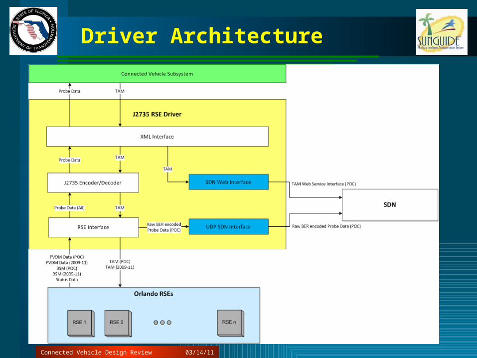
J2735 Driver
Probe Support– Support an incoming message from RSEs– Send incoming raw Probe data to SDN– Decode Probe data– Populate into XML formatting– Send to Subsystem
TAM– Decode XML from Subsystem– Send to SDN via web service interface– J2735 Encode– Send to RSEs at regular intervals
Connected Vehicle Design Review 03/14/11

9
Subsystem Architecture
Connected Vehicle Design Review 03/14/11

10
Subsystem Tasks
Probe– Collect Probe data by RSE
• Aggregate by Detection Zone– Log Probe data to the database– Send out to Databus for C2C and CV Driver
TAM– Receive TAM add/modify/delete messages– Maintain list of current messages– Notify J2735 Driver of message queue changes
Connected Vehicle Design Review 03/14/11
11
TSS Architecture
Connected Vehicle Design Review 03/14/11

12
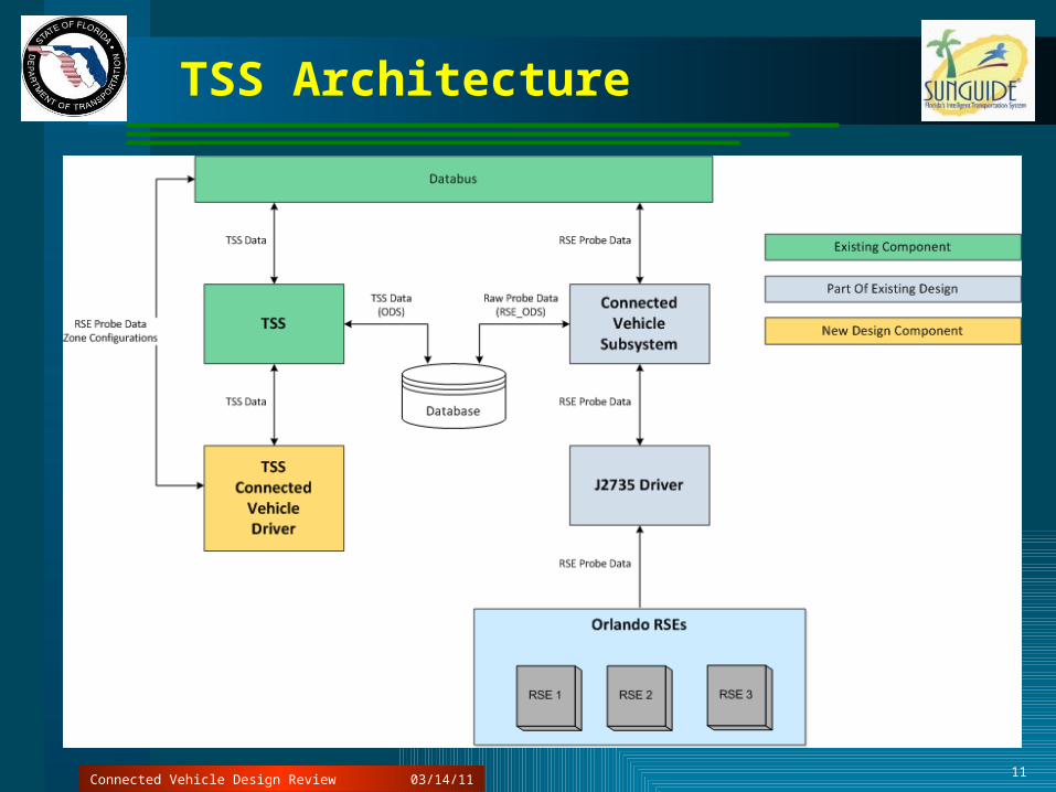
TSS CV Driver Tasks
Tasks– Add detectors and links– Map links to detectors– Read databus for updated zone readings– Push updates to TSS for new zone data
Configuration– One detector per RSE
• RSE and detector should be named the same– One link per detection Zone
Connected Vehicle Design Review 03/14/11
13
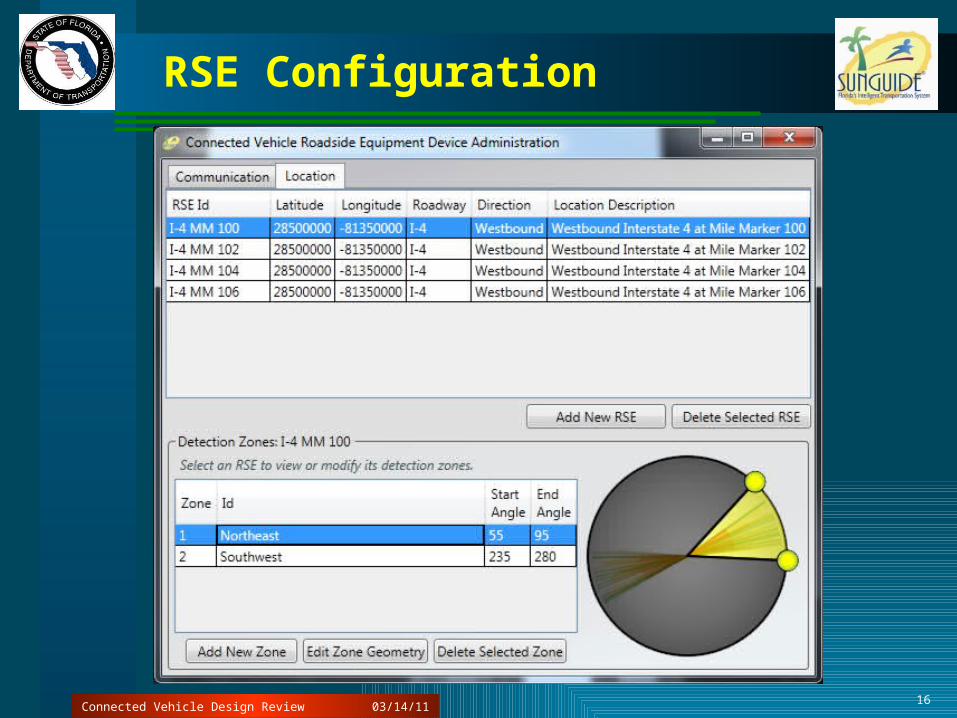
Special Notes on Detection Zones
Detection Zone may receive data from ANY RSE– OBE may store its data and pass it on to the next
RSE– Therefore, there is no link between RSE and
Detection Zone– Purely a connection for operational
understanding– Zones could potentially be split away from RSEs
Connected Vehicle Design Review 03/14/11

14
GUI Mockups
Connected Vehicle Design Review 03/14/11

15
RSE Configuration
Connected Vehicle Design Review 03/14/11
16
RSE Configuration
Connected Vehicle Design Review 03/14/11

17
Optional: Configuration Inspection
Connected Vehicle Design Review
This configuration is complex and may become out of sync Tool could assist in verifying configuration
Matches RSEs to detectors
Matches Zones Ids to lanes
Checks Zone/Name mismatches for consistency
03/14/11

18
RSE Status
Connected Vehicle Design Review 03/14/11

19
TAM Management
Change Management Board 03/14/11

20
TAM Editing
Connected Vehicle Design Review 03/14/11

21
Manually Defined TAM Presentation Region
Connected Vehicle Design Review 03/14/11
22
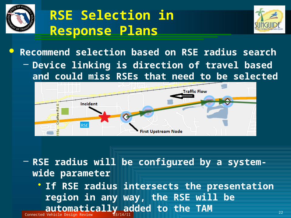
RSE Selection in Response Plans
Recommend selection based on RSE radius search– Device linking is direction of travel based and could
miss RSEs that need to be selected
– RSE radius will be configured by a system-wide parameter• If RSE radius intersects the presentation region in
any way, the RSE will be automatically added to the TAM
Connected Vehicle Design Review 03/14/11

23
RSE Selection in Response Plans
Recommend selection based on RSE radius search– Device linking is direction of travel based and could
miss RSEs that need to be selected
– RSE radius will be configured by a system-wide parameter• If RSE radius intersects the presentation region in
any way, the RSE will be automatically added to the TAM
Connected Vehicle Design Review 03/14/11
24
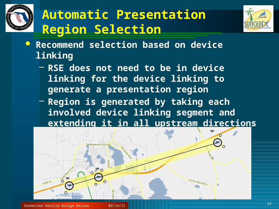
Automatic Presentation Region Selection
Recommend selection based on device linking– RSE does not need to be in device linking for the
device linking to generate a presentation region– Region is generated by taking each involved
device linking segment and extending it in all upstream directions by a configurable amount
– Accurate device linking file required
Connected Vehicle Design Review 03/14/11

25
Automatic Presentation Region Selection
Multiple regions can be included as part of a single TAM
Auto generation would generate multiple regions– Solves issue of travelers in multiple directions
Connected Vehicle Design Review 03/14/11

26
Response Plan Dialog
Connected Vehicle Design Review
Managed by TAM not by RSE All aspects of the TAM can be modified before
activating the response plan
03/14/11
27
Alerting
Connected Vehicle Design Review
Alerts for speed would be handled through TSS like all other speed alarms– Threshold would be configured on a link basis– Consistent with TSS
There would be no alerting for “TBD” fields at this time– Could be added as an enhancement when fields
are better defined
03/14/11
28
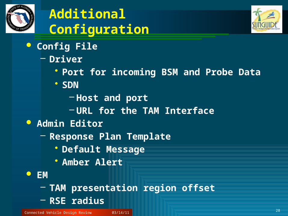
Additional Configuration
Config File– Driver
• Port for incoming BSM and Probe Data• SDN
– Host and port– URL for the TAM Interface
Admin Editor– Response Plan Template
• Default Message• Amber Alert
EM– TAM presentation region offset– RSE radius
Connected Vehicle Design Review 03/14/11
29
Questions
03/14/11Connected Vehicle Design Review