Embed Size (px)
Citation preview
(“The Charter Oak” Charles D. Brownell, 1857)
CONNECTICUT DEPARTMENTOF TRANSPORTATION
HIGHWAY DESIGN MANUALJANUARY 1999
(Includes March 2000 Revisions & Errata)

PREFACE
The Connecticut Highway Design Manual has been developed to provide uniform design practices forpreparing roadway plans. The Manual presents most of the information normally required in the design ofa typical highway project. The highway designer should attempt to meet all criteria presented in theManual; however, the Manual should not be considered a standard that must be met regardless ofimpacts. The highway designer must consider the social, economic or environmental impacts that result fromthe design values selected. The highway designer should develop solutions that meet the Department’soperational and safety requirements while preserving the aesthetic, historic or cultural resources of an area.The Department has designated certain highways or segments of highways that abut significant natural orcultural features as Scenic Highways. The criteria for and listing of Scenic Highways is included in anAppendix to Chapter One. Designers must exercise good judgment on individual projects and, frequently,they must be imaginative, innovative and flexible in their approach to highway design. Designers arereminded that the projects they work on are not just Department projects, but everyone’s project.
The Department has developed alternative design standards for bridge rehabilitation projects under theLocal Bridge Program. These alternative design standards may be applied to municipally maintained bridgeson facilities that are functionally classified as “Rural Local Roads,” “Rural Minor Collectors,” or “UrbanLocal Streets.”
The Department of Transportation wishes to thank the following organizations for their assistance duringthe development of this Manual:
< Federal Highway Administration,< Council of Small Towns,< Rural Development Council,< Connecticut Trust for Historic Preservation,< Councils of Elected Officials,< Regional Councils of Government,< Regional Planning Agencies, and< Connecticut Council on the Arts.
FOREWORD
Connecticut is blessed with an exceptionally strong sense of time and place, its bustling towns and quietvillages linked by a web of roads, some of which began before the coming of Columbus as trails and pathslinking Indian settlements. Whether local resident or visitor to the State, drivers know the experience ofthe journey can be a lot more than just getting from one point to the next.
The Connecticut landscape is one of great diversity. There are very few places in the country where youcan see such varied and distinctive landscapes, all within a two-hour drive. Connecticut has mountainousand rolling uplands dropping down to broad agricultural plateaus, dissected by rocky, fast-moving streams.Connecticut has broad and fertile river valleys framed by distinctive landforms that have supported mostof the urban population for its recent history. Connecticut has distinctive coastal plains separated by rockyoutcrops and extensive salt marshes.
Beyond exceptional natural land forms, the State is blessed with a similar range of diversity in the wayspeople have inhabited the land. As was the case along much of the eastern seaboard, people settledConnecticut in a series of episodes that adapted to conditions of the land and changes in technology. Forthe first 120 or so years, the economy was agrarian, and the landscape was covered with small farms andhomesteads. As technology evolved and industrialization began, these forms shifted and urban centersdeveloped.
There are scenic places in both of these landscape types. Within the urban regions, the scenic qualities area result of tenacious efforts by citizens to preserve what is left of the visible links between the land andpeople. Here, the scenic qualities are a result of relative scarcity. In the more rural regions, the scenicqualities are a result of tenacious efforts at making a living from the land. Scenic qualities are a result ofcontinuous stewardship and care.
The rich heritage of Connecticut needs to continue. Highway and bridge engineers, amongst many others,are key players in achieving this goal. Engineers have the challenge to not only maintain and upgrade thetransportation system to meet the operational and safety needs of the Department, but also to minimize theenvironmental, historic, cultural, aesthetic, social and economic impacts.
March 2000 TABLE OF CONTENTS TC-1
Table of ContentsCONNECTICUT HIGHWAY DESIGN MANUAL
Preface
Foreword
Table of Contents
Date of Revisions
Chapter One . . . . . . . . . . . . . . . . . . . . . . . . . . . . . . . . . . . . . . . . . . . . . . . . . . . MANUAL USAGE
Chapter Two . . . . . . . . . . . . . . . . . . . . . . . GEOMETRIC DESIGN OF EXISTING HIGHWAYS(3R Non-Freeway Projects)
Chapter Three . . . . . . . . . . . . . . . . . . . . . GEOMETRIC DESIGN OF EXISTING HIGHWAYS(4R Freeway Projects)(Spot Improvements)
Chapter Four . . . . . . . . . . . . . . . . . . . . . . . . . . . . . . . . . . . RURAL HIGHWAYS AND ROADS(New Construction/Major Reconstruction)
Chapter Five . . . . . . . . . . . . . . . . . . . . . . . . . . . . . . . . . . URBAN HIGHWAYS AND STREETS(New Construction/Major Reconstruction)
Chapter Six . . . . . . . . . . . . . . . . . . . . . . . . . . . . . . . . . . . . . . . . . . . . . . . . DESIGN CONTROLS
Chapter Seven . . . . . . . . . . . . . . . . . . . . . . . . . . . . . . . . . . . . . . . . . . . . . . . . SIGHT DISTANCE
Chapter Eight . . . . . . . . . . . . . . . . . . . . . . . . . . . . . . . . . . . . . . . . HORIZONTAL ALIGNMENT
Chapter Nine . . . . . . . . . . . . . . . . . . . . . . . . . . . . . . . . . . . . . . . . . . . VERTICAL ALIGNMENT
Chapter Ten . . . . . . . . . . . . . . . . . . . . . . . . . . . . . . . . . . . . . . . . . . . . . . . . . . CROSS SECTIONS
Chapter Eleven . . . . . . . . . . . . . . . . . . . . . . . . . . . . . . . . . . . . . . INTERSECTIONS AT-GRADE
Chapter Twelve . . . . . . . . . . . . . . . . . . . . . . . . . . . . . . . . . . . . . . . . . . . . . . . . INTERCHANGES
Chapter Thirteen . . . . . . . . . . . . . . . . . . . . . . . . . . . . . . . . . . . . . . . . . . . . ROADSIDE SAFETY
Chapter Fourteen . . . . . . . . . . . . . . . . . . MAINTENANCE AND PROTECTION OF TRAFFICTHROUGH CONSTRUCTION ZONES
Chapter Fifteen . . . . . . . . . . . . . . . . . . . . . . . . . . . . . . . . . . . . . SPECIAL DESIGN ELEMENTS

March 2000 TABLE OF CONTENTS TC-2
Glossary
Index

LIST OF SECTIONS SHOWING LATEST DATE OF REVISIONS
ORIGINAL ISSUE DATE IS JANUARY 1999
Section SectionNumber Date Number Date
March 2000 TABLE OF CONTENTS TC-3
1-1.01-1.011-1.021-1.031-1.041-2.01-2.011-2.021-2.031-2.041-2.051-2.061-2.071-2.081-2.091-2.101-2.111-2.121-2.131-2.141-2.152-1.02-2.02-2.012-2.01.012-2.01.022-2.01.032-2.022-2.032-2.042-2.052-3.0Figure 2-3A March 2000Figure 2-3B March 2000Figure 2-3C March 2000
Figure 2-3D March 2000Figure 2-3E March 2000Figure 2-3F March 2000Figure 2-3G March 2000Figure 2-3H March 2000Figure 2-3I March 20002-4.02-4.012-4.022-4.032-5.02-5.012-5.022-6.02-6.012-6.022-6.032-7.02-7.012-7.022-7.02.012-7.02.022-7.032-7.042-8.02-9.02-9.012-9.01.012-9.01.022-9.022-10.02-10.012-10.022-10.032-10.04

LIST OF SECTIONS SHOWING LATEST DATE OF REVISIONS
ORIGINAL ISSUE DATE IS JANUARY 1999
Section SectionNumber Date Number Date
March 2000 TABLE OF CONTENTS TC-4
3-1.03-1.013-1.023-1.033-1.043-1.04.013-1.04.023-1.04.033-1.04.043-1.04.053-1.04.063-2.03-2.013-2.023-2.03Figure 4A March 2000Figure 4B March 2000Figure 4C March 2000Figure 4D March 2000Figure 4E March 2000Figure 4F March 2000Figure 4G March 2000Figure 4H March 2000Figure 4IFigure 4JFigure 5A March 2000Figure 5B March 2000Figure 5C March 2000Figure 5D March 2000Figure 5E March 2000Figure 5F March 2000Figure 5G March 2000Figure 5H March 2000Figure 5I March 2000Figure 5J March 2000
Figure 5KFigure 5LFigure 5M March 20006-1.06-1.016-1.01.016-1.01.026-1.01.036-1.026-1.02.016-1.02.026-1.02.036-1.036-1.03.016-1.03.026-2.06-2.016-2.026-2.036-3.06-3.016-3.026-3.036-4.06-5.06-5.016-5.01.016-5.01.026-5.01.036-5.01.04 March 20006-5.01.056-5.026-6.06-6.016-6.02 March 2000

LIST OF SECTIONS SHOWING LATEST DATE OF REVISIONS
ORIGINAL ISSUE DATE IS JANUARY 1999
Section SectionNumber Date Number Date
March 2000 TABLE OF CONTENTS TC-5
6-6.036-6.03.016-6.03.026-6.046-7.07-1.07-2.07-2.017-2.027-3.08-1.08-2.08-2.018-2.028-2.02.018-2.02.028-2.02.038-2.038-2.03.018-2.03.028-2.03.038-2.03.048-2.03.058-2.03.068-2.03.078-2.048-2.04.018-2.04.028-2.04.038-2.04.048-2.04.058-2.058-3.08-3.018-3.02
8-3.02.018-3.02.028-3.02.038-3.038-3.049-1.09-1.019-1.029-2.09-2.019-2.029-2.039-2.049-2.04.019-2.04.029-2.04.039-3.09-3.019-3.029-3.039-4.09-5.010-1.010-1.0110-1.01.0110-1.01.021-1.0210-1.02.0110-1.02.0210-1.0310-1.0410-1.0510-1.05.0110-1.05.0210-1.05.03
LIST OF SECTIONS SHOWING LATEST DATE OF REVISIONS
ORIGINAL ISSUE DATE IS JANUARY 1999
Section SectionNumber Date Number Date
March 2000 TABLE OF CONTENTS TC-6
10-1.05.0410-2.010-2.0110-2.01.0110-2.01.0210-2.0210-2.0310-3.010-3.010-3.0110-3.0210-3.02.0110-3.02.0210-3.02.0310-4.010-4.0110-4.01.0110-4.01.0210-4.0210-5.010-6.010-7.011-1.011-1.0111-1.01.0111-1.01.0211-1.0211-1.0311-1.0411-1.04.0111-1.04.0211-1.0511-2.011-2.0111-2.01.01 March 2000
11-2.01.0211-2.01.03 March 200011-2.01.0411-2.02 March 200011-2.0311-3.011-3.0111-3.0211-3.0311-3.03.0111-3.03.0211-3.03.0311-3.03.0411-3.03.0511-4.011-4.0111-4.0211-4.02.0111-4.02.0211-4.02.0311-4.02.0411-4.02.0511-5.011-5.0111-5.0211-5.0311-5.0411-5.05 March 200011-5.0611-6.011-6.0111-6.0211-6.0311-7.011-7.01

LIST OF SECTIONS SHOWING LATEST DATE OF REVISIONS
ORIGINAL ISSUE DATE IS JANUARY 1999
Section SectionNumber Date Number Date
March 2000 TABLE OF CONTENTS TC-7
11-7.0211-8.011-8.0111-8.01.0111-8.01.0211-8.0211-8.0311-9.012-1.012-1.0112-1.01.0112-1.01.0212-1.0212-1.02.0112-1.02.0212-2.012-2.0112-2.0212-2.0312-2.0412-2.0512-2.0612-3.012-3.0112-3.01.0112-3.01.02 March 200012-3.01.0312-3.01.0412-3.01.0512-3.0212-3.02.01 March 200012-3.02.0212-3.02.0312-4.012-4.01
12-4.02 March 200012-4.03 March 200012-4.04 March 200012-5.012-5.0112-5.0212-5.0312-6.013-1.0113-2.013-2.0113-2.0213-2.0313-2.0413-3.013-3.0113-3.0213-3.0313-3.0413-3.0513-3.0613-3.0713-3.08 June 199913-4.013-4.0113-4.01.0113-4.01.0213-4.01.0313-4.01.0413-4.01.0513-4.01.0613-4.01.0713-4.01.0813-4.0213-4.03
LIST OF SECTIONS SHOWING LATEST DATE OF REVISIONS
ORIGINAL ISSUE DATE IS JANUARY 1999
Section SectionNumber Date Number Date
March 2000 TABLE OF CONTENTS TC-8
13-4.03.0113-4.03.0213-5.013-5.0113-5.0213-5.02.0113-5.02.0213-5.02.0313-5.02.0413-5.02.0513-5.0313-5.03.0113-5.0413-5.0513-5.05.0113-5.05.0213-6.013-6.0113-6.0213-6.0313-6.0413-6.0513-6.0613-6.0713-6.0813-6.0913-6.09.0113-6.09.0213-6.1013-6.1113-7.013-7.0113-7.01.0113-7.01.0213-7.01.03
13-7.01.0413-7.0213-7.02.01 March 200013-7.02.0213-7.02.0313-7.02.04 March 200013-7.02.05 March 200013-8.0Appendix March 200014-1.014-1.0114-1.0214-2.014-2.0114-2.0214-3.014-3.0114-3.0214-3.0314-3.0414-3.0514-4.014-4.0114-4.0214-4.0314-4.0414-4.0514-5.015-1.015-1.0115-1.0215-1.0315-1.03.0115-1.03.0215-1.04

LIST OF SECTIONS SHOWING LATEST DATE OF REVISIONS
ORIGINAL ISSUE DATE IS JANUARY 1999
Section SectionNumber Date Number Date
March 2000 TABLE OF CONTENTS TC-9
15-1.0515-1.05.0115-1.05.0215-1.0615-1.0715-1.0815-1.08.0115-1.08.0215-1.08.0315-1.08.0415-1.0915-2.015-2.0115-2.0215-2.02.0115-2.02.0215-2.02.0315-2.02.0415-2.0315-3.015-3.0115-3.01.0115-3.01.0215-3.0215-3.02.0115-3.02.0215-3.02.0315-3.02.0415-4.015-4.0115-4.0215-4.0315-5.015-5.0115-5.02
15-5.02.0115-5.02.0215-5.02.0315-6.015-6.0115-6.0215-6.0315-6.0415-6.04.0115-6.04.0215-6.04.03 March 200015-6.04.0415-6.04.0515-6.04.0615-6.04.0715-6.04.0815-6.0515-7.015-7.0115-7.0215-7.0315-7.0415-7.0515-8.0

March 2000 TABLE OF CONTENTS TC-10
January 1999 MANUAL USAGE 1-i
Chapter One
MANUAL USAGE
Table of Contents
Page
1-1.0 OVERVIEW . . . . . . . . . . . . . . . . . . . . . . . . . . . . . . . . . . . . . . . . . . . . . . . . . . . . . . 1-1(1)
1-1.01 Objective . . . . . . . . . . . . . . . . . . . . . . . . . . . . . . . . . . . . . . . . . . . . . . . . . 1-1(1) 1-1.02 Scope . . . . . . . . . . . . . . . . . . . . . . . . . . . . . . . . . . . . . . . . . . . . . . . . . . 1-1(1) 1-1.03 Basis for Design . . . . . . . . . . . . . . . . . . . . . . . . . . . . . . . . . . . . . . . . . . . . 1-1(3)
1-2.0 MANUAL SUMMARY . . . . . . . . . . . . . . . . . . . . . . . . . . . . . . . . . . . . . . . . . . . . . . 1-2(1)
1-2.01 Introduction . . . . . . . . . . . . . . . . . . . . . . . . . . . . . . . . . . . . . . . . . . . . . . . 1-2(1) 1-2.02 Chapter Two “Geometric Design of Existing Highways (3R Non-
Freeway Projects)” . . . . . . . . . . . . . . . . . . . . . . . . . . . . . . . . . . . . . . . . . 1-2(1) 1-2.03 Chapter Three “Geometric Design of Existing Highways (4R Non-
Freeway Projects ) (Spot Improvements)” . . . . . . . . . . . . . . . . . . . . . . . . 1-2(1) 1-2.04 Chapter Four “Rural Highways and Roads (New Construction/Major
Reconstruction)” . . . . . . . . . . . . . . . . . . . . . . . . . . . . . . . . . . . . . . . . . . . 1-2(2) 1-2.05 Chapter Five “Urban Highways and Streets (New Construction/Major
Reconstruction)” . . . . . . . . . . . . . . . . . . . . . . . . . . . . . . . . . . . . . . . . . . . 1-2(2) 1-2.06 Chapter Six “Design Controls” . . . . . . . . . . . . . . . . . . . . . . . . . . . . . . . . . 1-2(2) 1-2.07 Chapter Seven “Sight Distance” . . . . . . . . . . . . . . . . . . . . . . . . . . . . . . . . 1-2(3) 1-2.08 Chapter Eight “Horizontal Alignment” . . . . . . . . . . . . . . . . . . . . . . . . . . . . 1-2(3) 1-2.09 Chapter Nine “Vertical Alignment” . . . . . . . . . . . . . . . . . . . . . . . . . . . . . . 1-2(3) 1-2.10 Chapter Ten “Cross Sections” . . . . . . . . . . . . . . . . . . . . . . . . . . . . . . . . . 1-2(4) 1-2.11 Chapter Eleven “Intersections At-Grade” . . . . . . . . . . . . . . . . . . . . . . . . . 1-2(4) 1-2.12 Chapter Twelve “Interchanges” . . . . . . . . . . . . . . . . . . . . . . . . . . . . . . . . 1-2(4) 1-2.13 Chapter Thirteen “Roadside Safety” . . . . . . . . . . . . . . . . . . . . . . . . . . . . . 1-2(5) 1-2.14 Chapter Fourteen “Maintenance and Protection of Traffic Through
Construction Zones” . . . . . . . . . . . . . . . . . . . . . . . . . . . . . . . . . . . . . . . . . 1-2(5) 1-2.15 Chapter Fifteen “Special Design Elements” . . . . . . . . . . . . . . . . . . . . . . . . 1-2(6)

1-1(ii) MANUAL USAGE January 1999
January 1999 MANUAL USAGE 1-1(1)
Chapter One
MANUAL USAGE
1-1.0 OVERVIEW
1-1.01 Objective
The Connecticut Highway Design Manual has been prepared to provide guidance on the geometricdesign of bridge and highway projects. If used conscientiously and diligently, the Manual should be asignificant benefit to designers in selecting cost-effective designs that will meet the objectives of the localcommunity and those of the Department. Each project should be designed as part of the total environment,specifically designed to fit into the context of the area where it will be constructed. The design produced,especially those within rural areas, should reflect the natural, scenic and cultural landscape of the area.Where practical, designers should take advantage of the physical and topographical characteristics of anarea to maximize aesthetics. For a highway project to ultimately be successful, public involvement must beestablished early in the design process so that a common goal may be achieved. Included as an Appendixto Chapter One is the executive summary from the Department’s A Guide for Public Outreach, whichhas been prepared by the Office of Communications.
Throughout the design process, a designer may need to use the flexibility provided by this Manual toproduce a design solution that satisfies diverse and occasionally conflicting interests. To aid in building anunderstanding of sensitivity and flexibility in design, the Federal Highway Administration has produced aguide, Flexibility in Highway Design. Designers should refer to this guide for examples of projects thathave successfully integrated aesthetic, historic and scenic values along with safety and mobility. Also, theDepartment has produced a number of corridor studies for State-designated “Scenic Roads,” which arereferenced at the end of Chapter Two. These studies include recommendations that will allow for roadwayimprovements while protecting the scenic character of these roadways. Designers should be familiar withthese studies and should consider applying some of the design tools included in these studies to otherprojects within sensitive areas.
1-1.02 Scope
The Connecticut Highway Design Manual provides design criteria for the following highway elements:
1-1(2) MANUAL USAGE January 1999
1. geometrics;2. roadside safety;3. maintenance and protection of traffic through construction zones; and4. special design elements:
a. accessibility for disabled individuals,b. bikeways,c. landscaping,d. commuter lots, ande. fencing.
The designer should be aware of the projects’ surrounding environment and carefully integrate the designwithin its context. Through site visits, the designer may develop an appreciation of the physicalcharacteristics of an area and an understanding of community values. The designer must be aware of theimpacts that result from rigidly applying the criteria contained within this Manual. The designer shouldcarefully evaluate each criterion so that the final design provides for safety and operational improvementbut in harmony with the aesthetic, historic and cultural resources of the community. The Manual providesflexibility to a designer through the use of a range of design values where appropriate. Where theapplication of the minimum design criteria results in unreasonably high construction costs or extreme impactsto the surrounding environment, the design exception process can address the use of lower than minimumdesign values on a case-by-case basis. See Section 6-6.0.
The proper design of a highway project requires input from various disciplines. Early coordination isrequired so that their input may be effectively incorporated into the final design of a project. Their inputmay impact the original scope or change the character of the project. The design of a highway project willlikely include the evaluation and design of the following elements:
1. pavement design and rehabilitation;2. hydraulic design of drainage appurtenances;3. traffic engineering elements (e.g., traffic signals, lighting, signs, pavement markings);4. geotechnical elements (e.g., slope stability, soil bearing strength);5. structural design elements (e.g., bridges, culverts, retaining walls);6. environmental considerations including:
a. noise,b. water quality,c. biological resources, andd. historical resources;

January 1999 MANUAL USAGE 1-1(3)
7. right-of-way impacts (e.g., property owners, utilities, railroads); and8. highway capacity.
1-1.03 Basis for Design
The Connecticut Highway Design Manual has been structured to select the applicable set of designcriteria based on the following factors:
1. urban/rural location;2. design classification, based primarily on the extent of roadside development;3. the functional class of the facility:
a. freeway,b. arterial,c. collector, ord. local; and
4. the project scope of work:
a. new construction,b. 4R freeways,c. major reconstruction (non-freeways),d. 3R (non-freeways), ore. spot improvements.

1-1(4) MANUAL USAGE January 1999
January 1999 MANUAL USAGE 1-2(1)
1-2.0 MANUAL SUMMARY
1-2.01 Introduction
The following summarizes the content of each chapter within the Connecticut Highway Design Manual.
1-2.02 Chapter Two “Geometric Design of Existing Highways (3R Non-Freeway Projects)”
ConnDOT often programs highway improvements on existing non-freeways for reasons other thangeometric or safety deficiencies (e.g., pavement deterioration). These projects typically must be designedwithin restrictive right-of-way, financial and environmental constraints. Therefore, the design criteria for newconstruction are often not attainable without major and, frequently, unacceptable adverse impacts. At thesame time, however, the Department must take the opportunity to make cost-effective, practicalimprovements to the geometric design of existing highways and streets.
For these reasons, the Department has adopted in Chapter Two revised limits for geometric design criteriafor projects on existing non-freeways which are, in many cases, lower than the values for new construction.These criteria are based on a sound, engineering assessment of the underlying principles behind geometricdesign and on how the criteria for new construction can be legitimately modified to apply to existinghighways without sacrificing highway safety.
Chapter Two presents the Department's criteria for 3R non-freeway projects. These criteria are intendedto find the balance among many competing and conflicting objectives. These include the objective ofimproving Connecticut's existing highways; the objective of minimizing the adverse impacts of highwayconstruction on existing highways; and the objective of improving the greatest number of kilometers withinthe available funds.
1-2.03 Chapter Three “Geometric Design of Existing Highways (4R Freeway Projects) (SpotImprovements)”
Based on the same approach to 3R non-freeway projects in Chapter Two, Chapter Three presentsmodified geometric design criteria for:
1. 4R freeway projects, and2. spot improvement projects.
1-2(2) MANUAL USAGE January 1999
The design criteria for these two project scopes of work reflect the practical constraints of designing highwayimprovements on existing facilities.
1-2.04 Chapter Four “Rural Highways and Roads (New Construction/Major Reconstruction)”
Chapter Four presents a set of summary tables of geometric design criteria for new construction/ majorreconstruction projects in rural areas based on:
1. functional classification;
2. design classification on non-freeways (based on the average number of access points per kilometerper side); and
3. for arterials, two-lane versus multi-lane.
These tables provide the Manual user with a convenient summary of the geometric design criteria whichapply to a specific facility. The tables also identify the controlling design criteria which require a writtendesign exception if not met.
1-2.05 Chapter Five “Urban Highways and Streets (New Construction/Major Reconstruction)”
Chapter Five presents a set of summary tables of geometric design criteria for new construction/ majorreconstruction projects in urban areas based on:
1. functional classification;2. design classification on non-freeways (based on the type of area); and3. for arterials, two-lane versus multi-lane.
These tables provide the Manual user with a convenient summary of the geometric design criteria whichapply to a specific facility. The tables also identify the controlling design criteria which require a writtendesign exception if not met.
1-2.06 Chapter Six “Design Controls”
Proper highway design must reflect the consideration of many basic design controls which provide the overallframework for highway design. Chapter Six discusses the Department’s application of these controls,including:

January 1999 MANUAL USAGE 1-2(3)
1. highway systems (e.g., functional classification, Federal-aid);2. the various speed measurements (e.g., design speed);3. highway capacity analyses;4. access control; and5. project scope of work.
Chapter Six also discusses the Department’s process for requesting a design exception for those geometricdesign values which do not meet the Department’s criteria.
1-2.07 Chapter Seven “Sight Distance”
Sufficient sight distance is critical to safe highway operations. Chapter Seven presents ConnDOT criteriafor various sight distance elements, including stopping sight distance and decision sight distance. TheChapter also discusses the application of the two sight distance parameters. Intersection sight distance isaddressed in Chapter Eleven “Intersections At-Grade.”
1-2.08 Chapter Eight “Horizontal Alignment”
Highway horizontal alignment has a significant impact on highway safety and construction costs. ChapterEight presents ConnDOT criteria which will establish the alignment of a highway facility. This includes:
1. types of horizontal curves;2. minimum radii;3. superelevation development (e.g., transition lengths, axis of rotation); and4. sight distance around horizontal curves.
Because of their different operating conditions, Chapter Eight presents separate criteria for all ruralhighways/high-speed urban highways (V $ 80 km/h) and for low-speed urban streets (V # 70 km/h).
1-2.09 Chapter Nine “Vertical Alignment”
Highway vertical alignment, perhaps more so than any other highway element, has a significant impact onconstruction costs and highway operations, especially where there is an appreciable volume of trucks.Chapter Nine presents ConnDOT criteria on vertical alignment, including:
1. maximum and minimum grades,2. critical lengths of grade,

1-2(4) MANUAL USAGE January 1999
3. warrants and design for climbing lanes,4. the design of crest and sag vertical curves, and5. vertical clearances.
1-2.10 Chapter Ten “Cross Sections”
The highway cross section has a significant impact on the driver’s perception of the serviceability and safetyof the highway facility. Chapter Ten presents ConnDOT criteria on cross section elements to supplementthe design values in Chapters Two, Four and Five. Chapter Ten discusses:
1. the roadway section (e.g., travel lanes, shoulders, cross slopes, parking lanes, curbs);2. roadside elements (e.g., sidewalks, fill slopes, cut sections);3. medians;4. cross sections for bridges and underpasses; and5. right-of-way.
1-2.11 Chapter Eleven “Intersections At-Grade”
Intersections at-grade represent major points of conflict between crossing flows of traffic. Driver delay isinevitable because of the need to assign right-of-way, and accidents often cluster about intersections.Therefore, they merit considerable attention in highway design. Chapter Eleven presents ConnDOT criteriafor the design of intersections at-grade, including:
1. general design controls (e.g., capacity, selection of design vehicle, alignment, profile);2. intersection sight distance;3. design for right turns;4. turning roadways;5. auxiliary turning lanes (e.g., warrants, length, dual turn lanes);6. median openings;7. channelization; and8. driveways.
1-2.12 Chapter Twelve “Interchanges”
Interchanges offer the safest and most effective method to accommodate traffic operations between twointersecting highways. However, their high cost and significant impacts limit their application to freewaysand other selected major facilities. Chapter Twelve presents ConnDOT criteria for the selection and designof interchanges, including:
January 1999 MANUAL USAGE 1-2(5)
1. warrants;2. types;3. traffic operations (e.g., lane balance, lane reduction, capacity);4. freeway/ramp junctions (e.g., exit and entrance ramps);5. geometric design of ramps; and6. design of the ramp/crossing road intersection.
1-2.13 Chapter Thirteen “Roadside Safety”
Regardless of the highway engineering design, a certain number of vehicles will run off the road. Theroadside design should provide these drivers with a reasonable opportunity to recover and safely returnto the highway. This is accomplished through the availability of a clear roadside and/or the installation,where warranted, of protective barriers. Chapter Thirteen presents ConnDOT criteria for roadside safety,including:
1. clear zone criteria;2. guide rail warrants;3. guide rail types and selection;4. median barriers (e.g., warrants, types, design); 5. guide rail layout and design (e.g., length of need, flare rates, placement behind curbs); and6. crash cushions/end treatments.
1-2.14 Chapter Fourteen “Maintenance and Protection of Traffic Through Construction Zones”
A significant portion of the Department’s future highway program will be to upgrade existing facilities.Because this will inevitably disrupt existing traffic operations, Chapter Fourteen presents ConnDOT criteriaon traffic control through construction zones to minimize operational and safety problems. The Chapterdiscusses:
1. the ConnDOT responsibilities for maintenance and protection of traffic,2. traffic control management,3. geometric design through the construction zone, and4. roadside safety through the construction zone.

1-2(6) MANUAL USAGE January 1999
1-2.15 Chapter Fifteen “Special Design Elements”
In addition to the traditional highway design elements, the Department is responsible for ensuring that thehighway design properly incorporates a wide variety of special design elements. Chapter Fifteen presentsConnDOT criteria for these elements, including:
1. accessibility for disabled individuals,2. layout and design of commuter lots,3. location and design of bus stops,4. warrants and design of bikeways,5. landscaping,6. warrants and location for fencing, and7. design implications for noise barriers.
January 1999 MANUAL USAGE 1-A(1)
Appendix
This Appendix to Chapter One presents the following:
1. Criteria for Designation of Scenic Highways.
2. A Guide for Public Outreach, Executive Summary.

1-A(2) MANUAL USAGE January 1999
1 June 1, 1999
CRITERIA FOR DESIGNATION OFSCENIC HIGHWAYS
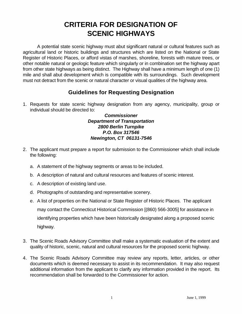
A potential state scenic highway must abut significant natural or cultural features such asagricultural land or historic buildings and structures which are listed on the National or StateRegister of Historic Places, or afford vistas of marshes, shoreline, forests with mature trees, orother notable natural or geologic feature which singularly or in combination set the highway apartfrom other state highways as being distinct. The Highway shall have a minimum length of one (1)mile and shall abut development which is compatible with its surroundings. Such developmentmust not detract from the scenic or natural character or visual qualities of the highway area.
Guidelines for Requesting Designation
1. Requests for state scenic highway designation from any agency, municipality, group orindividual should be directed to:
CommissionerDepartment of Transportation
2800 Berlin TurnpikeP.O. Box 317546
Newington, CT 06131-7546
2. The applicant must prepare a report for submission to the Commissioner which shall includethe following:
a. A statement of the highway segments or areas to be included.
b. A description of natural and cultural resources and features of scenic interest.
c. A description of existing land use.
d. Photographs of outstanding and representative scenery.
e. A list of properties on the National or State Register of Historic Places. The applicant
may contact the Connecticut Historical Commission [(860) 566-3005] for assistance in
identifying properties which have been historically designated along a proposed scenic
highway.
3. The Scenic Roads Advisory Committee shall make a systematic evaluation of the extent andquality of historic, scenic, natural and cultural resources for the proposed scenic highway.
4. The Scenic Roads Advisory Committee may review any reports, letter, articles, or other
documents which is deemed necessary to assist in its recommendation. It may also requestadditional information from the applicant to clarify any information provided in the report. Itsrecommendation shall be forwarded to the Commissioner for action.
2 June 1, 1999
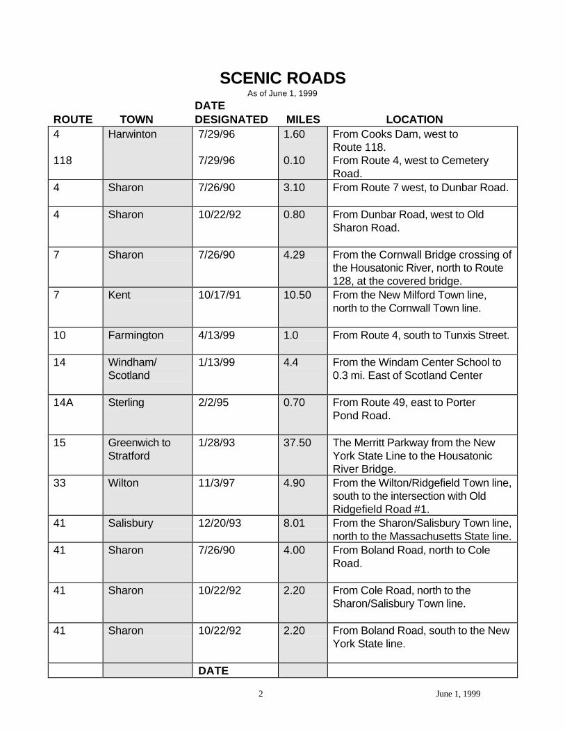
SCENIC ROADSAs of June 1, 1999
DATEROUTE TOWN DESIGNATED MILES LOCATION4
118
Harwinton 7/29/96
7/29/96
1.60
0.10
From Cooks Dam, west toRoute 118.From Route 4, west to CemeteryRoad.
4 Sharon 7/26/90 3.10 From Route 7 west, to Dunbar Road.
4 Sharon 10/22/92 0.80 From Dunbar Road, west to OldSharon Road.
7 Sharon 7/26/90 4.29 From the Cornwall Bridge crossing ofthe Housatonic River, north to Route128, at the covered bridge.
7 Kent 10/17/91 10.50 From the New Milford Town line,north to the Cornwall Town line.
10 Farmington 4/13/99 1.0 From Route 4, south to Tunxis Street.
14 Windham/Scotland
1/13/99 4.4 From the Windam Center School to0.3 mi. East of Scotland Center
14A Sterling 2/2/95 0.70 From Route 49, east to PorterPond Road.
15 Greenwich toStratford
1/28/93 37.50 The Merritt Parkway from the NewYork State Line to the HousatonicRiver Bridge.
33 Wilton 11/3/97 4.90 From the Wilton/Ridgefield Town line,south to the intersection with OldRidgefield Road #1.
41 Salisbury 12/20/93 8.01 From the Sharon/Salisbury Town line,north to the Massachusetts State line.
41 Sharon 7/26/90 4.00 From Boland Road, north to ColeRoad.
41 Sharon 10/22/92 2.20 From Cole Road, north to theSharon/Salisbury Town line.
41 Sharon 10/22/92 2.20 From Boland Road, south to the NewYork State line.
DATE
3 June 1, 1999
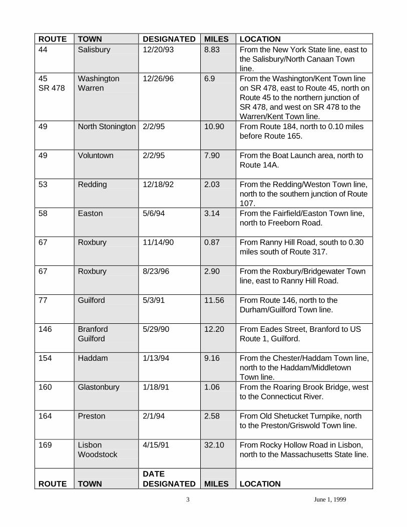
ROUTE TOWN DESIGNATED MILES LOCATION44 Salisbury 12/20/93 8.83 From the New York State line, east to
the Salisbury/North Canaan Townline.
45SR 478
WashingtonWarren
12/26/96 6.9 From the Washington/Kent Town lineon SR 478, east to Route 45, north onRoute 45 to the northern junction ofSR 478, and west on SR 478 to theWarren/Kent Town line.
49 North Stonington 2/2/95 10.90 From Route 184, north to 0.10 milesbefore Route 165.
49 Voluntown 2/2/95 7.90 From the Boat Launch area, north toRoute 14A.
53 Redding 12/18/92 2.03 From the Redding/Weston Town line,north to the southern junction of Route107.
58 Easton 5/6/94 3.14 From the Fairfield/Easton Town line,north to Freeborn Road.
67 Roxbury 11/14/90 0.87 From Ranny Hill Road, south to 0.30miles south of Route 317.
67 Roxbury 8/23/96 2.90 From the Roxbury/Bridgewater Townline, east to Ranny Hill Road.
77 Guilford 5/3/91 11.56 From Route 146, north to theDurham/Guilford Town line.
146 BranfordGuilford
5/29/90 12.20 From Eades Street, Branford to USRoute 1, Guilford.
154 Haddam 1/13/94 9.16 From the Chester/Haddam Town line,north to the Haddam/MiddletownTown line.
160 Glastonbury 1/18/91 1.06 From the Roaring Brook Bridge, westto the Connecticut River.
164 Preston 2/1/94 2.58 From Old Shetucket Turnpike, northto the Preston/Griswold Town line.
169 LisbonWoodstock
4/15/91 32.10 From Rocky Hollow Road in Lisbon,north to the Massachusetts State line.
ROUTE TOWNDATEDESIGNATED MILES LOCATION
4 June 1, 1999
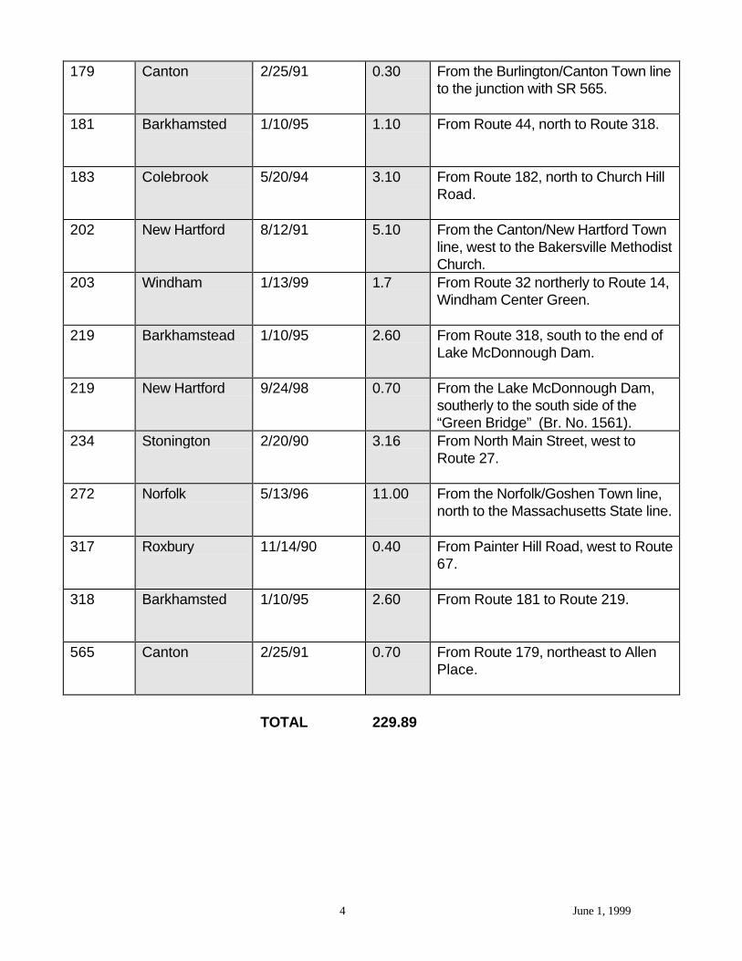
179 Canton 2/25/91 0.30 From the Burlington/Canton Town lineto the junction with SR 565.
181 Barkhamsted 1/10/95 1.10 From Route 44, north to Route 318.
183 Colebrook 5/20/94 3.10 From Route 182, north to Church HillRoad.
202 New Hartford 8/12/91 5.10 From the Canton/New Hartford Townline, west to the Bakersville MethodistChurch.
203 Windham 1/13/99 1.7 From Route 32 northerly to Route 14,Windham Center Green.
219 Barkhamstead 1/10/95 2.60 From Route 318, south to the end ofLake McDonnough Dam.
219 New Hartford 9/24/98 0.70 From the Lake McDonnough Dam,southerly to the south side of the“Green Bridge” (Br. No. 1561).
234 Stonington 2/20/90 3.16 From North Main Street, west toRoute 27.
272 Norfolk 5/13/96 11.00 From the Norfolk/Goshen Town line,north to the Massachusetts State line.
317 Roxbury 11/14/90 0.40 From Painter Hill Road, west to Route67.
318 Barkhamsted 1/10/95 2.60 From Route 181 to Route 219.
565 Canton 2/25/91 0.70 From Route 179, northeast to AllenPlace.
TOTAL 229.89
June 6, 1989 CONNECTICUT LAW JOURNAL____________________
1
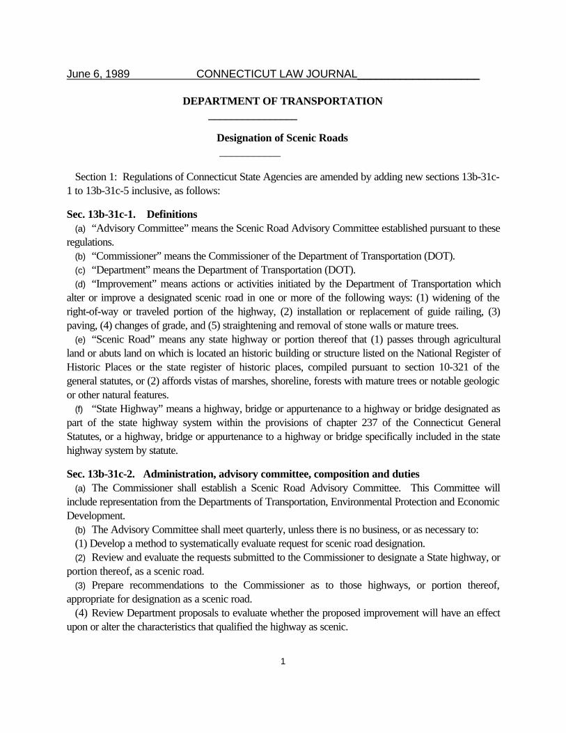
DEPARTMENT OF TRANSPORTATION ________________
Designation of Scenic Roads ___________
Section 1: Regulations of Connecticut State Agencies are amended by adding new sections 13b-31c-1 to 13b-31c-5 inclusive, as follows:
Sec. 13b-31c-1. Definitions(a) “Advisory Committee” means the Scenic Road Advisory Committee established pursuant to these
regulations.(b) “Commissioner” means the Commissioner of the Department of Transportation (DOT).(c) “Department” means the Department of Transportation (DOT).(d) “Improvement” means actions or activities initiated by the Department of Transportation which
alter or improve a designated scenic road in one or more of the following ways: (1) widening of theright-of-way or traveled portion of the highway, (2) installation or replacement of guide railing, (3)paving, (4) changes of grade, and (5) straightening and removal of stone walls or mature trees.
(e) “Scenic Road” means any state highway or portion thereof that (1) passes through agriculturalland or abuts land on which is located an historic building or structure listed on the National Register ofHistoric Places or the state register of historic places, compiled pursuant to section 10-321 of thegeneral statutes, or (2) affords vistas of marshes, shoreline, forests with mature trees or notable geologicor other natural features.
(f) “State Highway” means a highway, bridge or appurtenance to a highway or bridge designated aspart of the state highway system within the provisions of chapter 237 of the Connecticut GeneralStatutes, or a highway, bridge or appurtenance to a highway or bridge specifically included in the statehighway system by statute.
Sec. 13b-31c-2. Administration, advisory committee, composition and duties(a) The Commissioner shall establish a Scenic Road Advisory Committee. This Committee will
include representation from the Departments of Transportation, Environmental Protection and EconomicDevelopment.
(b) The Advisory Committee shall meet quarterly, unless there is no business, or as necessary to:(1) Develop a method to systematically evaluate request for scenic road designation.(2) Review and evaluate the requests submitted to the Commissioner to designate a State highway, or
portion thereof, as a scenic road.(3) Prepare recommendations to the Commissioner as to those highways, or portion thereof,
appropriate for designation as a scenic road.(4) Review Department proposals to evaluate whether the proposed improvement will have an effect
upon or alter the characteristics that qualified the highway as scenic.
June 6, 1989 CONNECTICUT LAW JOURNAL____________________
2
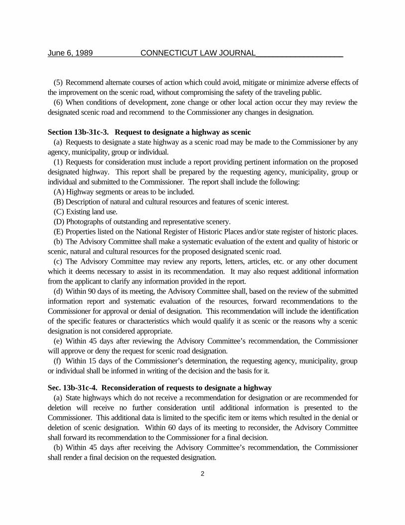
(5) Recommend alternate courses of action which could avoid, mitigate or minimize adverse effects ofthe improvement on the scenic road, without compromising the safety of the traveling public.
(6) When conditions of development, zone change or other local action occur they may review thedesignated scenic road and recommend to the Commissioner any changes in designation.
Section 13b-31c-3. Request to designate a highway as scenic(a) Requests to designate a state highway as a scenic road may be made to the Commissioner by any
agency, municipality, group or individual.(1) Requests for consideration must include a report providing pertinent information on the proposed
designated highway. This report shall be prepared by the requesting agency, municipality, group orindividual and submitted to the Commissioner. The report shall include the following:
(A) Highway segments or areas to be included.(B) Description of natural and cultural resources and features of scenic interest.(C) Existing land use.(D) Photographs of outstanding and representative scenery.(E) Properties listed on the National Register of Historic Places and/or state register of historic places.(b) The Advisory Committee shall make a systematic evaluation of the extent and quality of historic or
scenic, natural and cultural resources for the proposed designated scenic road.(c) The Advisory Committee may review any reports, letters, articles, etc. or any other document
which it deems necessary to assist in its recommendation. It may also request additional informationfrom the applicant to clarify any information provided in the report.
(d) Within 90 days of its meeting, the Advisory Committee shall, based on the review of the submittedinformation report and systematic evaluation of the resources, forward recommendations to theCommissioner for approval or denial of designation. This recommendation will include the identificationof the specific features or characteristics which would qualify it as scenic or the reasons why a scenicdesignation is not considered appropriate.
(e) Within 45 days after reviewing the Advisory Committee’s recommendation, the Commissionerwill approve or deny the request for scenic road designation.
(f) Within 15 days of the Commissioner’s determination, the requesting agency, municipality, groupor individual shall be informed in writing of the decision and the basis for it.
Sec. 13b-31c-4. Reconsideration of requests to designate a highway(a) State highways which do not receive a recommendation for designation or are recommended for
deletion will receive no further consideration until additional information is presented to theCommissioner. This additional data is limited to the specific item or items which resulted in the denial ordeletion of scenic designation. Within 60 days of its meeting to reconsider, the Advisory Committeeshall forward its recommendation to the Commissioner for a final decision.
(b) Within 45 days after receiving the Advisory Committee’s recommendation, the Commissionershall render a final decision on the requested designation.
June 6, 1989 CONNECTICUT LAW JOURNAL____________________
3
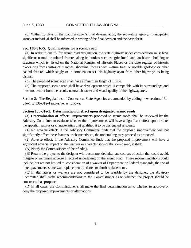
(c) Within 15 days of the Commissioner’s final determination, the requesting agency, municipality,group or individual shall be informed in writing of the final decision and the basis for it.
Sec. 13b-31c-5. Qualifications for a scenic road(a) In order to qualify for scenic road designation, the state highway under consideration must have
significant natural or cultural features along its borders such as agricultural land, an historic building orstructure which is listed on the National Register of Historic Places or the state register of historicplaces or affords vistas of marches, shoreline, forests with mature trees or notable geologic or othernatural features which singly or in combination set this highway apart from other highways as beingdistinct.
(b) The proposed scenic road shall have a minimum length of 1 mile.(c) The proposed scenic road shall have development which is compatible with its surroundings and
must not detract from the scenic, natural character and visual quality of the highway area.
Section 2: The Regulations of Connecticut State Agencies are amended by adding new sections 13b-31e-1 to 13b-31e-4 inclusive, as follows:
Section 13b-31e-1. Determination of effect upon designated scenic roads(a) Determination of effect: Improvements proposed to scenic roads shall be reviewed by the
Advisory Committee to evaluate whether the improvements will have a significant effect upon or alterthe specific features or characteristics that qualified it to be designated as scenic.
(1) No adverse effect: If the Advisory Committee finds that the proposed improvement will notsignificantly affect these features or characteristics, the undertaking may proceed as proposed.
(2) Adverse effect: If the Advisory Committee finds that the proposed improvement will have asignificant adverse impact on the features or characteristics of the scenic road, it shall:
(A) Notify the Commissioner of their finding.(B) Return the project to the designer with recommended alternate courses of action that could avoid,
mitigate or minimize adverse effects of undertaking on the scenic road. These recommendations couldinclude, but are not limited to, consideration of a waiver of Department or Federal standards, the use oftinted pavements, stone wall replacements and tree or shrub replacements.
(C) If alternatives or waivers are not considered to be feasible by the designer, the AdvisoryCommittee shall make recommendations to the Commissioner as to whether the project should beconstructed as proposed.
(D) In all cases, the Commissioner shall make the final determination as to whether to approve ordeny the proposed improvements or alternations.
June 6, 1989 CONNECTICUT LAW JOURNAL____________________
4
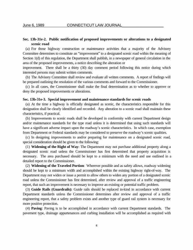
Sec. 13b-31e-2. Public notification of proposed improvements or alterations to a designatedscenic road
(a) For those highway construction or maintenance activities that a majority of the AdvisoryCommittee determines to constitute an “improvement” to a designated scenic road within the meaning ofSection 1(d) of this regulation, the Department shall publish, in a newspaper of general circulation in thearea of the proposed improvements, a notice describing the alteration orimprovement. There shall be a thirty (30) day comment period following this notice during whichinterested persons may submit written comments.
(b) The Advisory Committee shall review and evaluate all written comments. A report of findings willbe prepared outlining the resolution of the various comments and forward to the Commissioner.
(c) In all cases, the Commissioner shall make the final determination as to whether to approve ordeny the proposed improvements or alterations.
Sec. 13b-31e-3. Special improvement and maintenance standards for scenic roads(a) At the time a highway is officially designated as scenic, the characteristics responsible for this
designation shall be clearly identified and recorded. Any alteration to a scenic road shall maintain thesecharacteristics, if practical.
(b) Improvements to scenic roads shall be developed in conformity with current Department designand/or maintenance standards for the type road unless it is determined that using such standards willhave a significant adverse impact upon the roadway’s scenic characteristics. In which case, exemptionfrom Department or Federal standards may be considered to preserve the roadway’s scenic qualities.
(c) In designing improvements to and/or preparing for maintenance on a designated scenic road,special consideration should be given to the following:
(1) Widening of the Right of Way: The Department may not purchase additional property along adesignated scenic road unless the Commissioner has first determined that property acquisition isnecessary. The area purchased should be kept to a minimum with the need and use outlined in adetailed report to the Commissioner.
(2) Widening of the Traveled Portion: Wherever possible and as safety allows, roadway wideningshould be kept to a minimum width and accomplished within the existing highway right-of-way. TheDepartment may not widen or issue a permit to allow others to widen any portion of a designated scenicroad unless the Commissioner has first determined, after review and approval of a traffic engineeringreport, that such an improvement is necessary to improve an existing or potential traffic problem.
(3) Guide Rails (Guardrails): Guide rails should be replaced in-kind in accordance with currentDepartment standards unless the Commissioner determines after review and approval of a trafficengineering report, that a safety problem exists and another type of guard rail system is necessary formore positive protection.
(4) Paving: Paving is to be accomplished in accordance with current Department standards. Thepavement type, drainage appurtenances and curbing installation will be accomplished as required with

June 6, 1989 CONNECTICUT LAW JOURNAL____________________
5
consideration given to the characteristics of the scenic road. The width of paving should not extendmore than 12 inches beyond the existing shoulder.
(5) Changes of Grade: Wherever possible, proposed changes in grade should be designed to aminimum to restrict the impact on the scenic features. Changes of grade must be approved by theCommissioner after review and approval of a traffic engineering report where it has been determinedthat such an improvement is necessary to improve an existing or potential traffic problem.
(6) Straightening or Removal of Stone Walls: The Commissioner may approve the straighteningor removal of a stone wall after review and approval of a traffic engineering report that has determinedthat such action is necessary to improve an existing or potential safety hazard, improve a sight linerestriction, for installation of drainage appurtenances or for other sound reason. The Department willattempt, if practical, to relocate the stone wall within the highway right-of-way or on private property ofthe abutting property owner. The stone wall should be reconstructed in a manner consistent with itsformer appearance.
(7) Removal of Mature Trees: Wherever possible and as safety allows, mature trees within thehighway right-of-way should not be removed. If roadway widening is approved, the alignment shouldbe such as to restrict its impact on mature trees. The Commissioner may approve the removal ofmature trees after review of an engineering report which outlines the need.
(8) General Maintenance: All scenic roads shall receive the level of maintenance necessary forsafe public travel.
(9) Road Bed Maintenance: Necessary improvements, as determined by the Director ofMaintenance, may be made to improve safety, drainage or reduce a maintenance problem, but shall notdisturb the scenic characteristics for which the roadway was designated.
(10) Cross Drainage Maintenance: Cross drainage shall be maintained where necessary toprevent damage to the highway, possible washouts and other problems which may be detrimental to thesafety of the traveling public.
(11) Vegetation Maintenance: Where necessary for the safety and protection of the travelingpublic, tree branches and shrubs may be trimmed. Mowing shall be performed as necessary inaccordance with Department standards for health and safety requirements.
(12) Sign Maintenance: All information, regulatory, warning and identification signs shall be erectedand maintained as necessary or provided for by the State Traffic Commission.
(13) Winter Maintenance: Winter maintenance procedures shall be conducted in accordance withstandard Department policy. Snow and ice control shall be performed in accordance with the latestDepartment policy.
Sec. 13b-31e-4. Emergency repairsShould the Commissioner declare an emergency, as specified under Section 13b-26(f) of the General
Statutes, repairs will be made in a manner which will minimize, as much as reasonably possible, theeffect upon the features for which the highway was designated as scenic.
June 6, 1989 CONNECTICUT LAW JOURNAL____________________
6
Statement of purpose: To provide regulations for the designation of State highways as scenic roadsin accordance with Public Act No. 87-280.
Be it known that the foregoing regulations are adopted by the aforesaid agency pursuant to Public Act No. 87-280 of the PublicActs, after publication in the Connecticut Law Journal on March 8, 1988, of the notice of the proposal to adopt such regulations.
Wherefore, the foregoing regulations are hereby adopted, effective when filed with the Secretary of the State.In Witness Whereof: March 28, 1989, J. William Burns, Commissioner.Approved by the Attorney General as to legal sufficiency in accordance with Sec. 4-169, as amended, General Statutes: March
31, 1989.Approved by the Legislative Regulation Review Committee in accordance with Sec. 4-170, as amended, of the General Statues:
April 18, 1989.Two certified copies received and filed, and one such copy forwarded to the Commission on Official Legal Publications in
accordance with Sec. 4-172, as amended, of the General Statues, Secretary of State: May 1, 1989.


January 1999 3R NON-FREEWAY PROJECTS 2-i
Chapter Two
GEOMETRIC DESIGN OF EXISTING HIGHWAYS(3R Non-Freeway Projects)
Table of Contents
Page
2-1.0 INTRODUCTION . . . . . . . . . . . . . . . . . . . . . . . . . . . . . . . . . . . . . . . . . . . . . . . . . . . . . 2-1(1)
2-2.0 GENERAL . . . . . . . . . . . . . . . . . . . . . . . . . . . . . . . . . . . . . . . . . . . . . . . . . . . . . . . . . . 2-2(1)
2-2.01 Background . . . . . . . . . . . . . . . . . . . . . . . . . . . . . . . . . . . . . . . . . . . . . . . . . 2-2(1)
2-2.01.01 Federal 3R Regulations . . . . . . . . . . . . . . . . . . . . . . . . . . . . . 2-2(1) 2-2.01.02 Special Report 214 . . . . . . . . . . . . . . . . . . . . . . . . . . . . . . . . 2-2(1) 2-2.01.03 FHWA Technical Advisory T5040.28 . . . . . . . . . . . . . . . . . . . 2-2(2)
2-2.02 Objectives . . . . . . . . . . . . . . . . . . . . . . . . . . . . . . . . . . . . . . . . . . . . . . . . . . 2-2(3) 2-2.03 Approach . . . . . . . . . . . . . . . . . . . . . . . . . . . . . . . . . . . . . . . . . . . . . . . . . 2-2(4) 2-2.04 Application . . . . . . . . . . . . . . . . . . . . . . . . . . . . . . . . . . . . . . . . . . . . . . . . 2-2(5) 2-2.05 3R Project Evaluation . . . . . . . . . . . . . . . . . . . . . . . . . . . . . . . . . . . . . . . . . . 2-2(6)
2-3.0 3R GEOMETRIC DESIGN CRITERIA . . . . . . . . . . . . . . . . . . . . . . . . . . . . . . . . . . . . . . . 2-3(1)
Figure 2-3A Multi-Lane Rural Arterials (3R Projects) . . . . . . . . . . . . . . . . . . . . . . . . . . 2-3(2) Figure 2-3B Two-Lane Rural Arterials (3R Projects) . . . . . . . . . . . . . . . . . . . . . . . . . . 2-3(4) Figure 2-3C Rural Collector Roads (3R Projects) . . . . . . . . . . . . . . . . . . . . . . . . . . . . . 2-3(6)
Figure 2-3D Rural Local Roads (3R Projects) . . . . . . . . . . . . . . . . . . . . . . . . . . . . . . . 2-3(8) Figure 2-3E Multi-Lane Principal Urban Arterials (3R Projects) . . . . . . . . . . . . . . . . . . 2-3(10) Figure 2-3F Two-Lane Principal Urban Arterials (3R Projects) . . . . . . . . . . . . . . . . . . 2-3(12) Figure 2-3G Minor Urban Arterials (3R Projects) . . . . . . . . . . . . . . . . . . . . . . . . . . . . 2-3(14)
Figure 2-3H Urban Collector Streets (3R Projects) . . . . . . . . . . . . . . . . . . . . . . . . . . . 2-3(16)Figure 2-3I Local Urban Streets (3R Projects) . . . . . . . . . . . . . . . . . . . . . . . . . . . . . 2-3(18)
2-4.0 DESIGN CONTROLS . . . . . . . . . . . . . . . . . . . . . . . . . . . . . . . . . . . . . . . . . . . . . . . . . . . 2-4(1)
2-4.01 Design Speed . . . . . . . . . . . . . . . . . . . . . . . . . . . . . . . . . . . . . . . . . . . . . . 2-4(1) 2-4.02 Highway Capacity . . . . . . . . . . . . . . . . . . . . . . . . . . . . . . . . . . . . . . . . . . . 2-4(2) 2-4.03 Exceptions to Geometric Design Criteria . . . . . . . . . . . . . . . . . . . . . . . . . . . . 2-4(2)
2-5.0 HORIZONTAL ALIGNMENT . . . . . . . . . . . . . . . . . . . . . . . . . . . . . . . . . . . . . . . . . . . . . 2-5(1) 2-5.01 Rural Highways and High-Speed Urban Highways . . . . . . . . . . . . . . . . . . . . . 2-5(1) 2-5.02 Low-Speed Urban Streets . . . . . . . . . . . . . . . . . . . . . . . . . . . . . . . . . . . . . 2-5(1)

2-ii 3R NON-FREEWAY PROJECTS January 1999
Table of Contents(Continued)
Page 2-6.0 VERTICAL ALIGNMENT . . . . . . . . . . . . . . . . . . . . . . . . . . . . . . . . . . . . . . . . . . . . . . . 2-6(1)
2-6.01 Grades . . . . . . . . . . . . . . . . . . . . . . . . . . . . . . . . . . . . . . . . . . . . . . . . . . . 2-6(1) 2-6.02 Crest Vertical Curves . . . . . . . . . . . . . . . . . . . . . . . . . . . . . . . . . . . . . . . . . 2-6(1) 2-6.03 Sag Vertical Curves . . . . . . . . . . . . . . . . . . . . . . . . . . . . . . . . . . . . . . . . . . 2-6(1)
2-7.0 CROSS SECTIONS . . . . . . . . . . . . . . . . . . . . . . . . . . . . . . . . . . . . . . . . . . . . . . . . . . . . 2-7(1)
2-7.01 Widths . . . . . . . . . . . . . . . . . . . . . . . . . . . . . . . . . . . . . . . . . . . . . . . . . . . 2-7(1) 2-7.02 Bridges . . . . . . . . . . . . . . . . . . . . . . . . . . . . . . . . . . . . . . . . . . . . . . . . . . . 2-7(1)
2-7.02.01 Bridge Rehabilitation/Reconstruction . . . . . . . . . . . . . . . . . . . 2-7(1) 2-7.02.02 Bridges to Remain in Place . . . . . . . . . . . . . . . . . . . . . . . . . . 2-7(3)
2-7.03 Climbing Lanes . . . . . . . . . . . . . . . . . . . . . . . . . . . . . . . . . . . . . . . . . . . . . . 2-7(3) 2-7.04 Other Cross Section Elements . . . . . . . . . . . . . . . . . . . . . . . . . . . . . . . . . . . . 2-7(5)
2-8.0 SPECIAL DESIGN ELEMENTS . . . . . . . . . . . . . . . . . . . . . . . . . . . . . . . . . . . . . . . . . . . 2-8(1)
2-8.01 General . . . . . . . . . . . . . . . . . . . . . . . . . . . . . . . . . . . . . . . . . . . . . . . . . . . 2-8(1) 2-8.02 Traffic Calming . . . . . . . . . . . . . . . . . . . . . . . . . . . . . . . . . . . . . . . . . . . . . . 2-8(1)
2-9.0 ROADSIDE SAFETY . . . . . . . . . . . . . . . . . . . . . . . . . . . . . . . . . . . . . . . . . . . . . . . . . . . 2-9(1)
2-9.01 Clear Zones . . . . . . . . . . . . . . . . . . . . . . . . . . . . . . . . . . . . . . . . . . . . . . . . 2-9(1)
2-9.01.01 Basic 3R Criteria . . . . . . . . . . . . . . . . . . . . . . . . . . . . . . 2-9(1) 2-9.01.02 Rock Removal . . . . . . . . . . . . . . . . . . . . . . . . . . . . . . . . . . . 2-9(2)
2-9.02 Safety Appurtenances . . . . . . . . . . . . . . . . . . . . . . . . . . . . . . . . . . . . . . . . . 2-9(3)
2-10.0 INTERSECTIONS AT-GRADE . . . . . . . . . . . . . . . . . . . . . . . . . . . . . . . . . . . . . . . . . . 2-10(1)
2-10.01 Intersection Sight Distance . . . . . . . . . . . . . . . . . . . . . . . . . . . . . . . . . . . 2-10(1) 2-10.02 Turning Radii . . . . . . . . . . . . . . . . . . . . . . . . . . . . . . . . . . . . . . . . . . . . . 2-10(1) 2-10.03 Auxiliary Turning Lanes . . . . . . . . . . . . . . . . . . . . . . . . . . . . . . . . . . . . . 2-10(2) 2-10.04 Driveway Design . . . . . . . . . . . . . . . . . . . . . . . . . . . . . . . . . . . . . . . . . . 2-10(2)
2-11.0 REFERENCES . . . . . . . . . . . . . . . . . . . . . . . . . . . . . . . . . . . . . . . . . . . . . . . . . . . . . 2-11(1)
January 1999 3R NON-FREEWAY PROJECTS 2-1(1)
Chapter Two
GEOMETRIC DESIGNOF EXISTING HIGHWAYS
(3R Non-Freeway Projects)
2-1.0 INTRODUCTION
The geometric design of projects on existing highways must be viewed from a different perspective thanthat for a new construction project. These 3R projects are often initiated for reasons other than geometricdesign deficiencies (e.g., pavement deterioration), and they often must be designed within restrictive right-of-way, financial limitations and environmental constraints. Therefore, the design criteria for newconstruction are often not attainable without major and, frequently, unacceptable adverse impacts. These3R projects are initiated in communities where land use and cultural characteristics are well established.For these projects, it is essential to consider the community, land use, visual, historical and natural resourcessurrounding the proposed roadway improvement. Designers must be aware of the community context inwhich these projects are being proposed and select the design criteria accordingly. At the same time,however, the designer should take the opportunity to consider cost-effective, practical improvements tothe geometric design of existing highways and streets when accident data suggest it is appropriate. Thedesign produced should integrate these wide ranging and sometime conflicting issues to produce a safe andattractive transportation facility.
Designers should be aware of projects that are located within State- or town-designated “Scenic Roads”or “Scenic Byways.” The Department has produced a number of corridor studies for State- designatedscenic roads. These documents have been prepared in cooperation with the Department, local RegionalPlanning Agencies and other local interested parties. To protect the scenic character of these roadways,these studies include recommendations on land use, landscaping, view/scenic enhancements and geometricconsiderations. To ensure that proposed improvements on these scenic roadways will fit within the existingcharacter of the roadway, along with protecting their scenic and visual quality, the recommendations ofthese studies should be considered. Although these studies were prepared for specific segments ofroadway, designers should become familiar with the design tools presented in these documents andconsider their inclusion on other projects. Designers should also be aware of locally designated scenicroadways. Local governing authorities may have specific criteria established for these roadways. TheDepartment must be sensitive to these local issues and should incorporate their criteria where appropriate.
2-1(2) 3R NON-FREEWAY PROJECTS January 1999
For these reasons, the Department has adopted revised limits for geometric design criteria for projects onexisting highways which are, in many cases, lower than the values for new construction. These criteria arebased on a sound, engineering assessment of the underlying principles behind geometric design and on howthe criteria for new construction can be legitimately modified to apply to existing highways withoutsacrificing highway safety.
Chapter Two presents the Department's criteria for 3R non-freeway projects, and Chapter Three presentsthe criteria for 4R freeway projects and spot improvements (non-freeways). These criteria are intendedto find the balance among many competing and conflicting objectives. These include the objective ofimproving Connecticut's existing highways; the objective of minimizing the adverse impacts of highwayconstruction on existing highways; and the objective of improving the greatest number of kilometers withinthe available funds.

January 1999 3R NON-FREEWAY PROJECTS 2-2(1)
2-2.0 GENERAL
2-2.01 Background
2-2.01.01 Federal 3R Regulations
On June 10, 1982, the FHWA issued its Final Rule entitled Design Standards for Highways;Resurfacing, Restoration and Rehabilitation of Streets and Highways Other Than Freeways. ThisFinal Rule modified 23CFR Part 625 to adopt a flexible approach to the geometric design of 3R projects.Part 625 was modified again on March 31, 1983 to explicitly state that one objective of 3R projects is toenhance highway safety. In the Final Rule FHWA determined that it was not practical to adopt 3R designcriteria for nationwide application. Instead, each State can develop its own criteria and/or procedures forthe design of 3R projects, subject to FHWA approval. This allows each State to tailor its design criteriafor the 3R program according to the conditions which prevail within that State. This approach is in contrastto the application of criteria for new construction and major reconstruction, for which the AASHTO APolicy on Geometric Design of Highways and Streets provides nationwide criteria for application.
2-2.01.02 Special Report 214
In 1987, the Transportation Research Board published Special Report 214 Designing Safer Roads;Practices for Resurfacing, Restoration and Rehabilitation. This study was mandated by the SurfaceTransportation Assistance Act of 1982. The objective of the TRB study was to examine the safety cost-effectiveness of highway geometric design criteria and to recommend minimum design criteria for 3Rprojects on non-freeways. The final TRB report (SR214):
1. reviewed the existing 3R design practices of 15 State highway agencies and several local highwayagencies;
2. examined the relationship between highway accident potential and geometric design elements,based on the existing research literature and on special research projects commissioned as part ofthe TRB study;
3. examined the relationship between the extent of geometric design improvements and the cost of3R projects;
4. discussed the issue of cost-effectiveness relative to geometric design improvements on 3R projects;
5. reviewed the literature on tort liability and geometric design;

2-2(2) 3R NON-FREEWAY PROJECTS January 1999
6. presented a safety-conscious design process; and
7. presented specific numerical criteria for the geometric design of 3R projects for the followingelements:
a. lane and shoulder widths,b. horizontal curvature and superelevation,c. vertical curvature,d. bridge width,e. side slopes, andf. pavement cross slopes.
The SR214 information has been incorporated, where considered appropriate for Connecticut, into theDepartment's criteria and procedures for 3R projects. The designer should reference SR214 for morediscussion on 3R projects.
2-2.01.03 FHWA Technical Advisory T5040.28
Pursuant to its adoption of SR214, FHWA issued on October 17, 1988, Technical Advisory T5040.28"Developing Geometric Design Criteria and Processes for Non-Freeway RRR Projects." The purpose ofthe Advisory is to provide guidance on developing or modifying criteria for the design of Federal-aid, non-freeway 3R projects. The Advisory:
1. discusses the procedures for developing 3R criteria;
2. discusses the factors which should be evaluated in a safety-conscious design process;
3. discusses the application of design exceptions for the FHWA controlling design criteria on 3Rprojects; and
4. presents specific criteria for the design of 3R projects based on SR 214.
The information from the Technical Advisory has been incorporated, where considered appropriate forConnecticut, into the Department's criteria and procedures for 3R projects.
January 1999 3R NON-FREEWAY PROJECTS 2-2(3)
2-2.02 Objectives
From an overall perspective, the 3R program is intended to improve the greatest number of highwaykilometers within the available funds for highway projects. "Improve" is meant to apply to all aspects whichdetermine a facility's serviceability, including:
1. the structural integrity of the pavement, bridges and culverts;
2. the drainage design of the facility to, among other objectives, minimize ponding on the highway, toprotect the pavement structure from failure, and to prevent roadway flooding during the design-yearstorm;
3. from a highway capacity perspective, the level of service provided for the traffic flow;
4. the adequacy of access to abutting properties;
5. the geometric design of the highway to safely accommodate expected vehicular speeds and trafficvolumes;
6. the roadside safety design to reduce, within some reasonable boundary, the adverse impacts ofrun-off-the-road vehicles; and
7. the traffic control devices to provide the driver with critical information and to meet driverexpectancies.
These objectives are competing for the limited funds available for 3R projects on existing highways. TheDepartment's responsibility is to realize the greatest overall benefit from the available funds. Therefore, onindividual projects, some compromises may be necessary to achieve the goals of the overall highwayprogram. Specifically for geometric design and roadside safety, the compromise is between newconstruction criteria and what is practical for the specific conditions of each highway project.
Therefore, considering the above discussion, the Department has adopted and FHWA has approved itsapproach to the geometric design of 3R projects. The overall objective of the Department's criteria is tofulfill the requirements of the FHWA regulation and Technical Advisory which govern the 3R program.These objectives may be summarized as follows:
1. 3R projects are intended to extend the service life of the existing facility and to return its featuresto a condition of structural or functional adequacy.
2. 3R projects are intended to enhance highway safety.

2-2(4) 3R NON-FREEWAY PROJECTS January 1999
3. 3R projects are intended to incorporate cost-effective, practical improvements to the geometricdesign of the existing facility.
2-2.03 Approach
The Department's approach to the geometric design of 3R projects is to adopt, where justifiable, a revisedset of numerical criteria. The design criteria throughout the other Manual chapters provide the frame ofreference for the 3R criteria. The following summarizes the approach which has been used:
1. Design Speed. Figures 2-3A through 2-3I provide the values for design speed. Where the designspeed is based on actual speeds measured in the field, see Section 2-4.01 for the procedure thatshould be used for determining the recommended design speed. The design speed selected shouldbe consistent with respect to topography, the adjacent land use and the functional classification ofhighway.
2. Speed-Related Criteria. Many geometric design values are calculated directly from the designspeed (e.g., vertical curves, horizontal curve radii). The design speed is used to determine thesespeed-related criteria. For many of these elements, Chapter Two presents an acceptable thresholdvalue for the element which is considerably below the selected design speed. For example, if thedesign speed of an existing crest vertical curve is within 30 km/h of the 85th percentile speed andthere is not an adverse accident history, this is considered acceptable for the project without adesign exception.
3. Cross Section Widths. The criteria in Chapters Four and Five have been evaluated relative to thetypical constraints of 3R projects. Where justifiable, the lower values of the cross section widthcriteria have been reduced. The upper values from Chapters Four and Five have been incorporatedinto the 3R criteria to provide an upper range. This provides an expanded range of acceptablevalues for application on 3R projects. Where an existing roadway section exceeds the designminimum lane and shoulder widths, a proposed improvement should not result in a reduction to theexisting cross section without approval from the appropriate Division Manager. See Section 2-7.0for more discussion on cross section widths.
4. Other Design Criteria. The Department's Highway Design Manual contains many other detailson proper geometric design techniques. These criteria are directly applicable to new constructionand major reconstruction. For 3R projects, these criteria have been evaluated and a judgment hasbeen made on their proper application to 3R projects. Unless stated otherwise in this chapter, thecriteria in other chapters apply to 3R projects and should be incorporated, if practical.
January 1999 3R NON-FREEWAY PROJECTS 2-2(5)
5. Evaluation. The designer should evaluate available data (e.g., accident experience) whendetermining the geometric design of 3R projects. The necessary evaluations presented for 3Rprojects are based on the FHWA Technical Advisory T5040.28 “Developing Geometric DesignCriteria and Processes for Non-freeway RRR Projects.” Section 2-2.05 discusses 3R projectevaluation in more detail.
2-2.04 Application
The designer should realize the following factors when applying the design criteria in this chapter:
1. Trigger Values. The designer will be evaluating the existing geometric design against the criteria inthis chapter. If an existing geometric design feature does not at least meet the lower criteria, thedesigner must evaluate the practicality of improving the feature. Note that to use the design criteriain Sections 2-5.0 and 2-6.02, the selected design speed is based on the 85th percentile speed.
2. Improvement Level. The Department has determined that, once the decision is made to improvea geometric design element, the level of improvement should be compatible with the projectobjective. Where a range of values is presented, the designer should strive to avoid selectingcriteria from the lower range. The minimum acceptable level of improvement will be designated asone of the following:
a. In some cases, the 3R trigger value may be acceptable. For example, it will be acceptableto redesign sag vertical curves to meet the comfort criteria rather than the headlight sightdistance criteria. See Section 2-6.03.
b. In some cases, the trigger value may only be applicable to evaluating the need for animprovement, but a different value becomes the minimum acceptable level of improvement.For example, Figure 2-5A is used to evaluate the need for improvements to a horizontalcurve, but the criteria in Section 8-2.0 are used to make any improvements.
3. Exception Process. Desirably, the geometric design of 3R projects will meet all of the criteriapresented in this chapter. However, only key geometric design elements (i.e., the controlling designcriteria) require a formal exception when not met. The 3R design exception process is discussedin Section 2-4.03, which is the same as the exception process for new construction and majorreconstruction (Section 6-6.0).
2-2(6) 3R NON-FREEWAY PROJECTS January 1999
2-2.05 3R Project Evaluation
Sections 2-3.0 to 2-10.0 present the specific geometric design and roadside safety criteria which will be usedto determine the design of 3R projects. In addition, several other factors must be considered in a 3R project,and the designer should conduct applicable technical evaluations using appropriate Department units as maybe necessary. The possible evaluations are discussed below:
1. Conduct Field Review. The designer will normally conduct a thorough field review of the proposed3R project. Other personnel should accompany the designer as appropriate, including personnel fromtraffic, maintenance, construction, FHWA (NHS projects), etc. The objective of the field review
should be to identify potential safety hazards and potential safety improvements to the facility.
2. Document Existing Geometrics. The designer will normally review the most recent highway plansand combine this with the field review to determine the existing geometrics within the project limits.The review includes lane and shoulder widths, horizontal and vertical alignment, intersectiongeometrics and the roadside safety design.
3. Accident Experience. The accident data within the limits of the 3R project will be evaluated.
Accident data is available from the Bureau of Planning. The following accident data analyses shouldbe conducted:
a. Accident Rate versus Statewide Average (for that type facility). This will provide an overallindication of safety problems within the 3R project limits.
b. Accident Analysis by Type. This will indicate if certain types of accidents are a particularproblem. For example, a large number of head-on and/or sideswipe accidents may indicate
inadequate roadway width. A large number of fixed object accidents may indicate an inade-quate roadside clear zone.
c. Accident Analysis by Location. Accidents may cluster about certain locations, suc h a s ahorizontal curve or intersection. In particular, the analysis should check to see if any locationson the Department's Suggested Surveillance Study Sites, as identified by the Department'saccident data system, fall within the proposed project limits.
4. Speed Studies. As indicated in Section 2-4.01, the Division of Traffic Engineering will review existing
speed studies in the vicinity of the project and, if necessary, conduct a field study to determine thedesign speed of the 3R project. In addition, it may be desirable to conduct spot speed studies inspecific locations (e.g., in advance of a specific horizontal or vertical curve) to assist in thedetermination of geometric design improvements. The speed study should be conducted before thefield review.
January 1999 3R NON-FREEWAY PROJECTS 2-2(7)
5. Traffic Volumes. As indicated in Section 2-4.02, the traffic volumes used for design will range
between the current traffic volumes and those determined using a ten-year projection. This will
generate traffic volumes for any necessary highway capacity analyses. The designer should also
note that, in some cases, the Department’s 3R geometric design criteria will allow the acceptance
of geometric design values which may be considerably below those for new construction/major
reconstruction (e.g., for horizontal and vertical curves).
6. Early Coordination for Right-of-Way Acquisition. Significant ROW acquisitions are typically outside
the scope of 3R projects. However, the field, accident and/or speed studies may indicate the need
for selective safety improvements which would require ROW purchases. Therefore, the designer
should determine improvements which will be incorporated into the project design as early as feasible
and initiate the ROW acquisition process, if required.
7. Pavement Condition. 3R projects which are programmed because of a significant deterioration of the
pavement structure will generally be determined from the Department's Pavement Management
Program. The extent of deterioration will influence the decision on whether a project can be designed
using the 3R design criteria or whether it should be designed using major reconstruction criteria. A
3R project may include pavement reconstruction for up to a of the project length. The a limit may
be exceeded on a case-by-case basis with the approval from the appropriate Division Manager.
Whenever the proposed pavement improvement is major, it may be practical to include significant
geometric improvements (e.g., lane and shoulder widening) in the project design. However, the
proper level of geometric improvement is often determined by many additional factors other than the
extent of pavement improvement. These include available right-of-way, traffic volumes, accident
experience and available funds for the project. Therefore, it may be appropriate for the 3R project
to include, for example, full-depth pavement reconstruction and minimal geometric improvement, if
deemed proper, to meet the safety and operational objectives of the 3R program.
8. Geometric Design of Adjacent Highway Sections. The designer should examine the geometric
features and operating speeds of highway sections adjacent to the 3R project. This will include
investigating whether or not any highway improvements are in the planning stages. The 3R project
should provide design continuity with the adjacent sections. This involves a consideration of factors
such as driver expectancy, geometric design consistency and proper transitions between sections of
different geometric designs.
9. Physical Constraints. The physical constraints within the limits of the 3R project will often determine
what geometric improvements are practical and cost-effective. These include topography, adjacent
development, available right-of-way, utilities and environmental constraints (e.g., wetlands).
2-2(8) 3R NON-FREEWAY PROJECTS January 1999
10. Traffic Control Devices. All signing and pavement markings on 3R projects must meet the criteria
of the Manual on Uniform Traffic Control Devices (MUTCD). The Division of Traffic
Engineering is responsible for selecting and locating the traffic control devices on the project. The
designer should work with the Division of Traffic Engineering to identify possible geometric and
safety deficiencies which will remain in place (i.e., no improvement will be made). These include:
a. narrow bridges,
b. horizontal and vertical curves which do not meet the 3R criteria, and
c. roadside hazards within the clear zone.
January 1999 3R NON-FREEWAY PROJECTS 2-3(1)
2-3.0 3R GEOMETRIC DESIGN CRITERIA
Figures 2-3A through 2-3I present the Department's criteria for the design of 3R projects for both rural
and urban areas. The designer should consider the following in the use of the 3R design criteria:
1. Functional/Design Classification. The selection of design values for 3R projects depends on the
functional and design classification of the highway facility. This is discussed in Section 6-1.0.
For rural highways, the design classification is based on the average number of access points per
kilometer per side. The designer should realize that the values in the figures are for guidance only;
they should not be used as rigid criteria for determining the design classification on rural highways.
2. Cross Section Elements. The designer should realize that some of the cross section elements
included in the figure (e.g., median width) are not automatically warranted in the project design. The
values in the figures will only apply after the decision has been made to include the element in the
highway cross section.
3. Manual Section References. These figures are intended to provide a concise listing of design values
for easy use. However, the designer should review the Manual section references for greater
insight into the design elements.
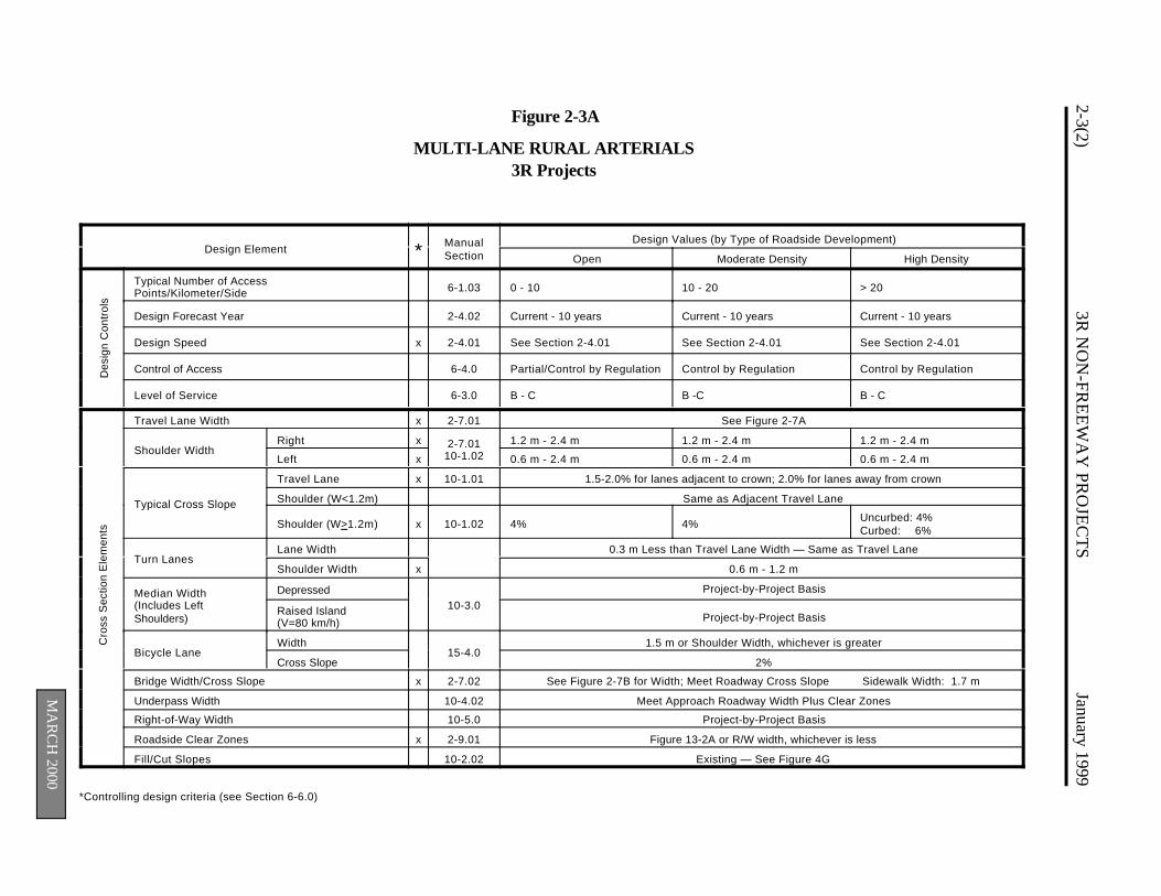
2-3(2)3R
NO
N-FR
EE
WA
Y PR
OJE
CT
SJanuary 1999
Cro
ss S
ectio
n E
lem
ents
MA
RC
H 2000
*Controlling design criteria (see Section 6-6.0)
Figure 2-3A
MULTI-LANE RURAL ARTERIALS3R Projects
Design Element * ManualSection
Design Values (by Type of Roadside Development)
Open Moderate Density High Density
Des
ign
Con
trol
s
Typical Number of AccessPoints/Kilometer/Side 6-1.03 0 - 10 10 - 20 > 20
Design Forecast Year 2-4.02 Current - 10 years Current - 10 years Current - 10 years
Design Speed x 2-4.01 See Section 2-4.01 See Section 2-4.01 See Section 2-4.01
Control of Access 6-4.0 Partial/Control by Regulation Control by Regulation Control by Regulation
Level of Service 6-3.0 B - C B -C B - C
Travel Lane Width x 2-7.01 See Figure 2-7A
Shoulder WidthRight x 2-7.01
10-1.021.2 m - 2.4 m 1.2 m - 2.4 m 1.2 m - 2.4 m
Left x 0.6 m - 2.4 m 0.6 m - 2.4 m 0.6 m - 2.4 m
Typical Cross Slope
Travel Lane x 10-1.01 1.5-2.0% for lanes adjacent to crown; 2.0% for lanes away from crown
Shoulder (W<1.2m) Same as Adjacent Travel Lane
Shoulder (W>1.2m) x 10-1.02 4% 4% Uncurbed: 4%Curbed: 6%
Turn LanesLane Width 0.3 m Less than Travel Lane Width — Same as Travel Lane
Shoulder Width x 0.6 m - 1.2 m
Median Width(Includes LeftShoulders)
Depressed10-3.0
Project-by-Project Basis
Raised Island(V=80 km/h) Project-by-Project Basis
Bicycle LaneWidth
15-4.01.5 m or Shoulder Width, whichever is greater
Cross Slope 2%
Bridge Width/Cross Slope x 2-7.02 See Figure 2-7B for Width; Meet Roadway Cross Slope Sidewalk Width: 1.7 m
Underpass Width 10-4.02 Meet Approach Roadway Width Plus Clear Zones
Right-of-Way Width 10-5.0 Project-by-Project Basis
Roadside Clear Zones x 2-9.01 Figure 13-2A or R/W width, whichever is less
Fill/Cut Slopes 10-2.02 Existing — See Figure 4G
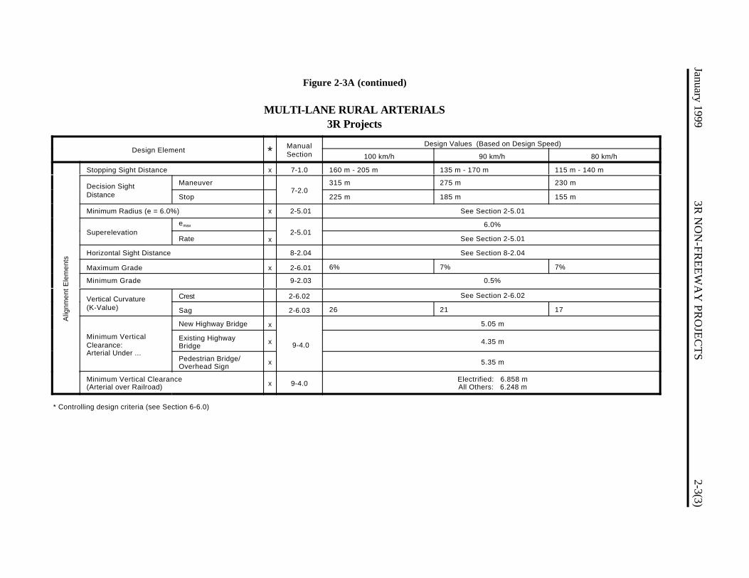
Figure 2-3A (continued)
MULTI-LANE RURAL ARTERIALS3R Projects
January 19993R
NO
N-FR
EE
WA
Y PR
OJE
CT
S2-3(3)
Alig
nmen
t Ele
men
ts
Design Element * ManualSection
Design Values (Based on Design Speed)
100 km/h 90 km/h 80 km/h
Stopping Sight Distance x 7-1.0 160 m - 205 m 135 m - 170 m 115 m - 140 m
Decision SightDistance
Maneuver7-2.0
315 m 275 m 230 m
Stop 225 m 185 m 155 m
Minimum Radius (e = 6.0%) x 2-5.01 See Section 2-5.01
Superelevationemax
2-5.016.0%
Rate x See Section 2-5.01
Horizontal Sight Distance 8-2.04 See Section 8-2.04
Maximum Grade x 2-6.01 6% 7% 7%
Minimum Grade 9-2.03 0.5%
Vertical Curvature(K-Value)
Crest 2-6.02 See Section 2-6.02
Sag 2-6.03 26 21 17
Minimum VerticalClearance:Arterial Under ...
New Highway Bridge x
9-4.0
5.05 m
Existing HighwayBridge x 4.35 m
Pedestrian Bridge/Overhead Sign x 5.35 m
Minimum Vertical Clearance(Arterial over Railroad) x 9-4.0 Electrified: 6.858 m
All Others: 6.248 m
* Controlling design criteria (see Section 6-6.0)
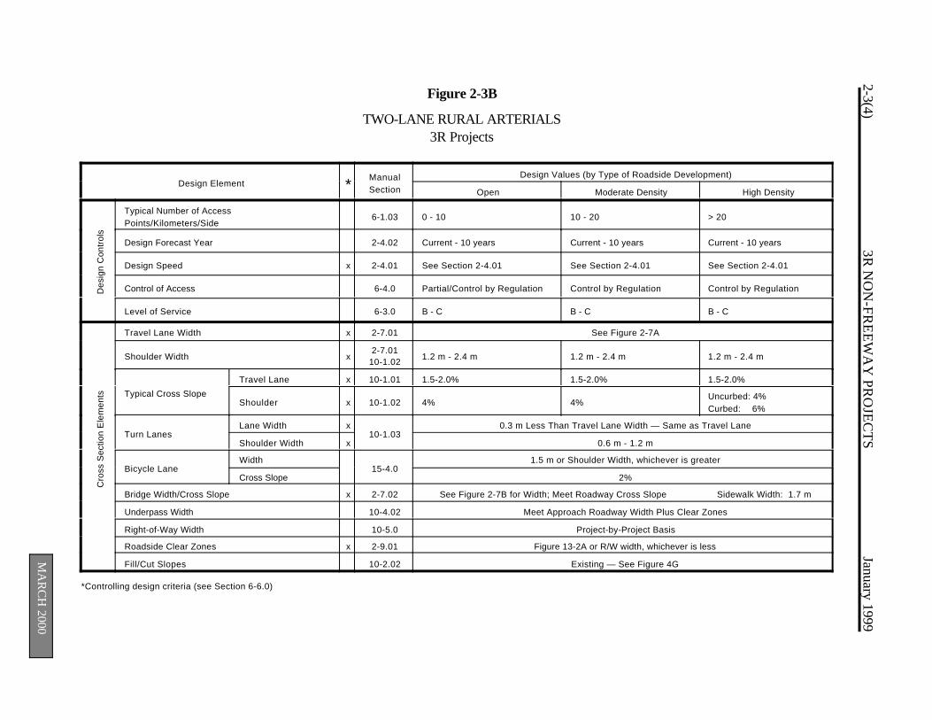
2-3(4)3R
NO
N-FR
EE
WA
Y PR
OJE
CT
SJanuary 1999
MA
RC
H 2000
*Controlling design criteria (see Section 6-6.0)
Figure 2-3B
TWO-LANE RURAL ARTERIALS3R Projects
Design Element *ManualSection
Design Values (by Type of Roadside Development)
Open Moderate Density High Density
Des
ign
Con
trol
s
Typical Number of AccessPoints/Kilometers/Side
6-1.03 0 - 10 10 - 20 > 20
Design Forecast Year 2-4.02 Current - 10 years Current - 10 years Current - 10 years
Design Speed x 2-4.01 See Section 2-4.01 See Section 2-4.01 See Section 2-4.01
Control of Access 6-4.0 Partial/Control by Regulation Control by Regulation Control by Regulation
Level of Service 6-3.0 B - C B - C B - C
Cro
ss S
ectio
n E
lem
ents
Travel Lane Width x 2-7.01 See Figure 2-7A
Shoulder Width x2-7.01
10-1.02 1.2 m - 2.4 m 1.2 m - 2.4 m 1.2 m - 2.4 m
Typical Cross Slope
Travel Lane x 10-1.01 1.5-2.0% 1.5-2.0% 1.5-2.0%
Shoulder x 10-1.02 4% 4%Uncurbed: 4%Curbed: 6%
Turn LanesLane Width x
10-1.030.3 m Less Than Travel Lane Width — Same as Travel Lane
Shoulder Width x 0.6 m - 1.2 m
Bicycle Lane Width
15-4.01.5 m or Shoulder Width, whichever is greater
Cross Slope 2%
Bridge Width/Cross Slope x 2-7.02 See Figure 2-7B for Width; Meet Roadway Cross Slope Sidewalk Width: 1.7 m
Underpass Width 10-4.02 Meet Approach Roadway Width Plus Clear Zones
Right-of-Way Width 10-5.0 Project-by-Project Basis
Roadside Clear Zones x 2-9.01 Figure 13-2A or R/W width, whichever is less
Fill/Cut Slopes 10-2.02 Existing — See Figure 4G
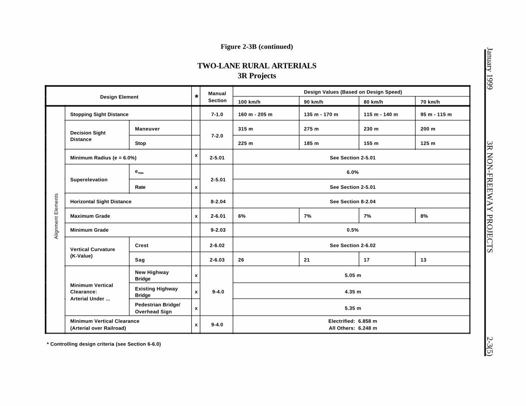
Figure 2-3B (continued)
TWO-LANE RURAL ARTERIALS3R Projects
January 19993R
NO
N-FR
EE
WA
Y PR
OJE
CT
S2-3(5)
Alig
nmen
t Ele
men
ts
Design Element *ManualSection
Design Values (Based on Design Speed)
100 km/h 90 km/h 80 km/h 70 km/h
Stopping Sight Distance 7-1.0 160 m - 205 m 135 m - 170 m 115 m - 140 m 95 m - 115 m
Decision SightDistance
Maneuver7-2.0
315 m 275 m 230 m 200 m
Stop 225 m 185 m 155 m 125 m
Minimum Radius (e = 6.0%) x 2-5.01 See Section 2-5.01
Superelevation
emax
2-5.016.0%
Rate x See Section 2-5.01
Horizontal Sight Distance 8-2.04 See Section 8-2.04
Maximum Grade x 2-6.01 6% 7% 7% 8%
Minimum Grade 9-2.03 0.5%
Vertical Curvature(K-Value)
Crest 2-6.02 See Section 2-6.02
Sag 2-6.03 26 21 17 13
Minimum VerticalClearance:Arterial Under ...
New HighwayBridge
x
9-4.0
5.05 m
Existing HighwayBridge
x 4.35 m
Pedestrian Bridge/Overhead Sign
x 5.35 m
Minimum Vertical Clearance(Arterial over Railroad)
x 9-4.0Electrified: 6.858 mAll Others: 6.248 m
* Controlling design criteria (see Section 6-6.0)

2-3(6)3R
NO
N-FR
EE
WA
Y PR
OJE
CT
SJanuary 1999
MA
RC
H 2000
Des
ign
Con
trol
s C
ross
Sec
tion
Ele
men
ts
*Controlling design criteria (see Section 6-6.0)
Figure 2-3C
RURAL COLLECTOR ROADS3R Projects
Design Element * ManualSection
Design Values (by Type of Roadside Development)
Open Moderate Density High Density
Typical Number of AccessPoints/Kilometers/Side 6-1.03 0 - 10 10 - 20 > 20
Design Forecast Year 2-4.02 Current - 10 years Current - 10 years Current - 10 years
Design Speed
AADT < 400
x 2-4.01
Posted Legal Speed Limit Posted Legal Speed Limit Posted Legal Speed Limit
AADT: 400 - 2000 60 km/h - 80 km/h 60 km/h - 80 km/h 60 km/h - 80 km/h
AADT > 2000 See Section 2-4.01 See Section 2-4.01 See Section 2-4.01
Control of Access 6-4.0 Control by Regulation Control by Regulation Control by Regulation
Level of Service 6-3.0 C - D C - D C - D
Travel Lane Width
AADT < 400
x 2-7.01 See Figure 2-7A See Figure 2-7A See Figure 2-7AAADT: 400 - 1500
AADT: 1500 - 2000
AADT > 2000
Shoulder Width x2-7.01
10-1.02 0.6 m - 2.4 m 0.6 m - 2.4 m 0.6 m - 2.4 m
Typical Cross Slope
Travel Lane x 10-1.01 1.5-2.0% for lanes adjacent to crown; 2.0% for lanes away from crown
Shoulder (W<1.2m) Same as Adjacent Travel Lanes
Shoulder (W>1.2m) x 10-1.02 4% Uncurbed: 4%Curbed: 6%
Uncurbed: 4%Curbed: 6%
Turn LanesLane Width x
10-1.030.3 m Less Than Travel Lane Width — Same as Travel Lane
Shoulder Width x 0.6 m - 1.2 m
Bicycle LaneWidth
15-4.01.5 m or Shoulder Width, whichever is greater
Cross Slope 2%
Bridge Width/Cross Slope x 2-7.02 See Figure 2-7B for Width; Meet Roadway Cross Slope Sidewalk Width: 1.7 m
Underpass Width 10-4.02 Meet Approach Roadway Width Plus Clear Zones
Right-of-Way Width 10-5.0 Project-by-Project Basis
Roadside Clear Zones x 2-9.01 Figure 13-2A or R/W width, whichever is less
Fill/Cut Slopes 10-2.02 Existing — See Figure 4G

Figure 2-3C (continued)
RURAL COLLECTOR ROADS3R Projects
Alig
nmen
t Ele
men
ts
January 19993R
NO
N-FR
EE
WA
Y PR
OJE
CT
S2-3(7)
Design Element * ManualSection
Design Values (Based on Design Speed)
90 km/h 80 km/h 70 km/h 60 km/h 50 km/h
Stopping Sight Distance x 7-1.0 135 m - 170 m 115 m - 140 m 95 m - 115 m 75 m - 85 m 60 m - 65 m
Decision SightDistance
Maneuver7-2.0
275 m 230 m 200 m 175 m 145 m
Stop 185 m 155 m 125 m 95 m 75 m
Minimum Radius (e = 6.0%) x 2-5.01 See Section 2-5.01
Superelevationemax
2-5.016.0%
Rate x See Section 2-5.01
Horizontal Sight Distance 8-2.04 See Section 8-2.04
Maximum Grade x 2-6.01 9% 9% 10% 10% 11%
Minimum Grade 9-2.03 0.5%
Vertical Curvature(K-Value)
Crest 2-6.02 See Section 2-6.02
Sag 2-6.03 21 17 13 10 7
Minimum VerticalClearance:Collector Under ...
New Highway Bridge x 9-4.0
4.5 m
Existing HighwayBridge x 4.35 m
Minimum Vertical Clearance(Collector over Railroad)
x 9-4.0 Electrified: 6.858 mAll Others: 6.248 m
* Controlling design criteria (see Section 6-6.0)

2-3(8)3R
NO
N-FR
EE
WA
Y PR
OJE
CT
SJanuary 1999
MA
RC
H 2000
Des
ign
Con
trol
s C
ross
Sec
tion
Ele
men
ts
*Controlling design criteria (see Section 6-6.0)
Figure 2-3D
RURAL LOCAL ROADS3R Projects
Design Element * ManualSection
Design Values (by Type of Roadside Development)
Open Moderate Density High Density
Typical Number of AccessPoints/Kilometers/Side 6-1.03 0 - 10 10 - 20 > 20
Design Forecast Year 2-4.02 Current - 10 years Current - 10 years Current - 10 years
Design Speed x 2-4.01 Posted Legal Speed Limit Posted Legal Speed Limit Posted Legal Speed Limit
Control of Access 6-4.0 Control by Regulation Control by Regulation Control by Regulation
Level of Service 6-3.0 C - D C - D C - D
Travel Lane Width x 2-7.01 2.7 m - 3.6 m 2.7 m - 3.6 m 2.7 m - 3.6 m
Shoulder Width x2-7.01
10-1.02 0.0 m - 1.2 m 0.0 m - 1.2 m 0.0 m - 1.2 m
Typical Cross Slope
Travel Lane x 10-1.01 1.5-2.0% 1.5-2.0% 1.5-2.0%
Shoulder (W<1.2m) Same as Adjacent Travel Lane
Shoulder (W>1.2m) x 10-1.02 4% Uncurbed: 4%Curbed: 6%
Uncurbed: 4%Curbed: 6%
Turn LanesLane Width x
10-1.032.7 m - 3.6 m
Shoulder Width x 0.0 m - 0.6 m
Bicycle Lane Width
15-4.01.5 m or Shoulder Width, whichever is greater
Cross Slope 2%
Bridge Width/Cross Slope x 2-7.02 See Figure 2-7B for Width; Meet Roadway Cross Slope Sidewalk Width: 1.7 m
Underpass Width 10-4.02 Meet Approach Roadway Width Plus Clear Zones
Right-of-Way Width 10-5.0 Project-by-Project Basis
Roadside Clear Zones x 2-9.01 Figure 13-2A or R/W width, whichever is less
Fill/Cut Slopes 10-2.02 Existing — See Figure 4G
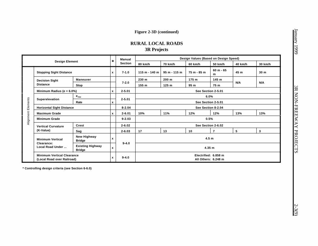
Figure 2-3D (continued)
RURAL LOCAL ROADS3R Projects
Alig
nmen
t Ele
men
ts
January 19993R
NO
N-FR
EE
WA
Y PR
OJE
CT
S2-3(9)
Design Element *ManualSection
Design Values (Based on Design Speed)
80 km/h 70 km/h 60 km/h 50 km/h 40 km/h 30 km/h
Stopping Sight Distance x 7-1.0 115 m - 140 m 95 m - 115 m 75 m - 85 m60 m - 65m 45 m 30 m
Decision SightDistance
Maneuver7-2.0
230 m 200 m 175 m 145 mN/A N/A
Stop 155 m 125 m 95 m 75 m
Minimum Radius (e = 6.0%) x 2-5.01 See Section 2-5.01
Superelevationemax
2-5.016.0%
Rate x See Section 2-5.01
Horizontal Sight Distance 8-2.04 See Section 8-2.04
Maximum Grade x 2-6.01 10% 11% 12% 12% 13% 13%
Minimum Grade 9-2.03 0.5%
Vertical Curvature(K-Value)
Crest 2-6.02 See Section 2-6.02
Sag 2-6.03 17 13 10 7 5 3
Minimum VerticalClearance:Local Road Under ...
New HighwayBridge
x
9-4.0
4.5 m
Existing HighwayBridge
x 4.35 m
Minimum Vertical Clearance(Local Road over Railroad) x 9-4.0
Electrified: 6.858 mAll Others: 6.248 m
* Controlling design criteria (see Section 6-6.0)
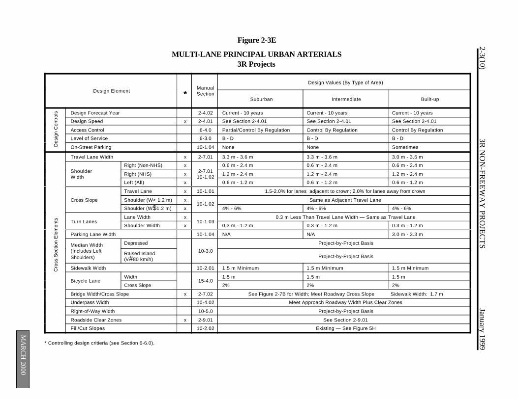
2-3(10)3R
NO
N-FR
EE
WA
Y PR
OJE
CT
SJanuary 1999
MA
RC
H 2000
Des
ign
Con
trol
sC
ross
Sec
tion
Ele
men
ts
Figure 2-3E
MULTI-LANE PRINCIPAL URBAN ARTERIALS3R Projects
Design Element *ManualSection
Design Values (By Type of Area)
Suburban Intermediate Built-up
Design Forecast Year 2-4.02 Current - 10 years Current - 10 years Current - 10 years
Design Speed x 2-4.01 See Section 2-4.01 See Section 2-4.01 See Section 2-4.01
Access Control 6-4.0 Partial/Control By Regulation Control By Regulation Control By Regulation
Level of Service 6-3.0 B - D B - D B - D
On-Street Parking 10-1.04 None None Sometimes
Travel Lane Width x 2-7.01 3.3 m - 3.6 m 3.3 m - 3.6 m 3.0 m - 3.6 m
Shoulder Width
Right (Non-NHS) x2-7.01
10-1.02
0.6 m - 2.4 m 0.6 m - 2.4 m 0.6 m - 2.4 m
Right (NHS) x 1.2 m - 2.4 m 1.2 m - 2.4 m 1.2 m - 2.4 m
Left (All) x 0.6 m - 1.2 m 0.6 m - 1.2 m 0.6 m - 1.2 m
Cross Slope
Travel Lane x 10-1.01 1.5-2.0% for lanes adjacent to crown; 2.0% for lanes away from crown
Shoulder (W< 1.2 m) x10-1.02
Same as Adjacent Travel Lane
Shoulder (W$1.2 m) x 4% - 6% 4% - 6% 4% - 6%
Turn LanesLane Width x
10-1.030.3 m Less Than Travel Lane Width — Same as Travel Lane
Shoulder Width x 0.3 m - 1.2 m 0.3 m - 1.2 m 0.3 m - 1.2 m
Parking Lane Width 10-1.04 N/A N/A 3.0 m - 3.3 m
Median Width (Includes Left Shoulders)
Depressed
10-3.0
Project-by-Project Basis
Raised Island(V#80 km/h) Project-by-Project Basis
Sidewalk Width 10-2.01 1.5 m Minimum 1.5 m Minimum 1.5 m Minimum
Bicycle Lane Width
15-4.01.5 m 1.5 m 1.5 m
Cross Slope 2% 2% 2%
Bridge Width/Cross Slope x 2-7.02 See Figure 2-7B for Width; Meet Roadway Cross Slope Sidewalk Width: 1.7 m
Underpass Width 10-4.02 Meet Approach Roadway Width Plus Clear Zones
Right-of-Way Width 10-5.0 Project-by-Project Basis
Roadside Clear Zones x 2-9.01 See Section 2-9.01
Fill/Cut Slopes 10-2.02 Existing — See Figure 5H
* Controlling design critieria (see Section 6-6.0).
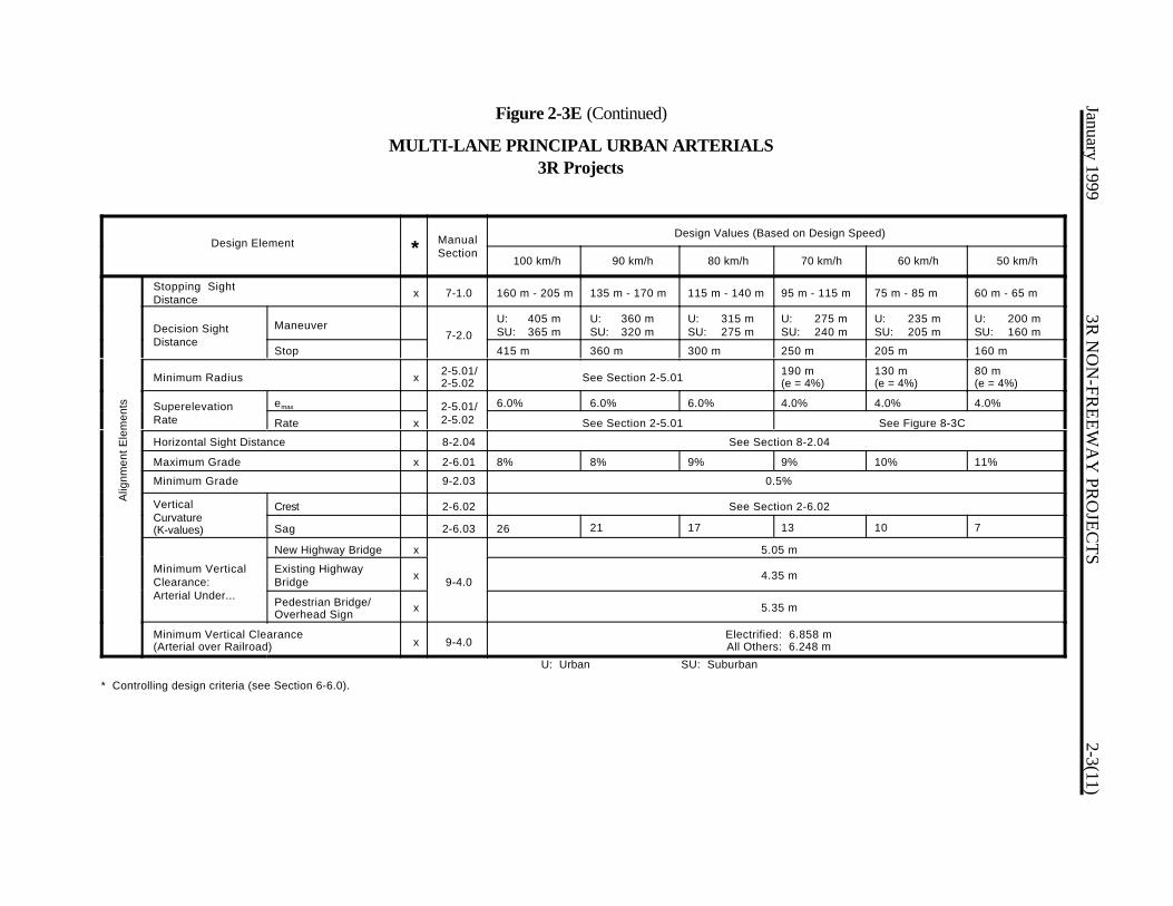
January 19993R
NO
N-FR
EE
WA
Y PR
OJE
CT
S2-3(11)
Figure 2-3E (Continued)
MULTI-LANE PRINCIPAL URBAN ARTERIALS3R Projects
Design Element * ManualSection
Design Values (Based on Design Speed)
100 km/h 90 km/h 80 km/h 70 km/h 60 km/h 50 km/h
Stopping Sight Distance x 7-1.0 160 m - 205 m 135 m - 170 m 115 m - 140 m 95 m - 115 m 75 m - 85 m 60 m - 65 m
Decision Sight Distance
Maneuver7-2.0
U: 405 mSU: 365 m
U: 360 mSU: 320 m
U: 315 mSU: 275 m
U: 275 mSU: 240 m
U: 235 mSU: 205 m
U: 200 mSU: 160 m
Stop 415 m 360 m 300 m 250 m 205 m 160 m
Minimum Radius x 2-5.01/2-5.02 See Section 2-5.01 190 m
(e = 4%)130 m(e = 4%)
80 m(e = 4%)
Superelevation Rate
emax 2-5.01/2-5.02
6.0% 6.0% 6.0% 4.0% 4.0% 4.0%
Rate x See Section 2-5.01 See Figure 8-3C
Horizontal Sight Distance 8-2.04 See Section 8-2.04
Maximum Grade x 2-6.01 8% 8% 9% 9% 10% 11%
Minimum Grade 9-2.03 0.5%
Vertical Curvature (K-values)
Crest 2-6.02 See Section 2-6.02
A
lignm
ent E
lem
ents
Sag 2-6.03 26 21 17 13 10 7
Minimum Vertical Clearance: Arterial Under...
New Highway Bridge x
9-4.0
5.05 m
Existing HighwayBridge x 4.35 m
Pedestrian Bridge/Overhead Sign x 5.35 m
Minimum Vertical Clearance (Arterial over Railroad) x 9-4.0
Electrified: 6.858 mAll Others: 6.248 m
* Controlling design criteria (see Section 6-6.0).
U: Urban SU: Suburban
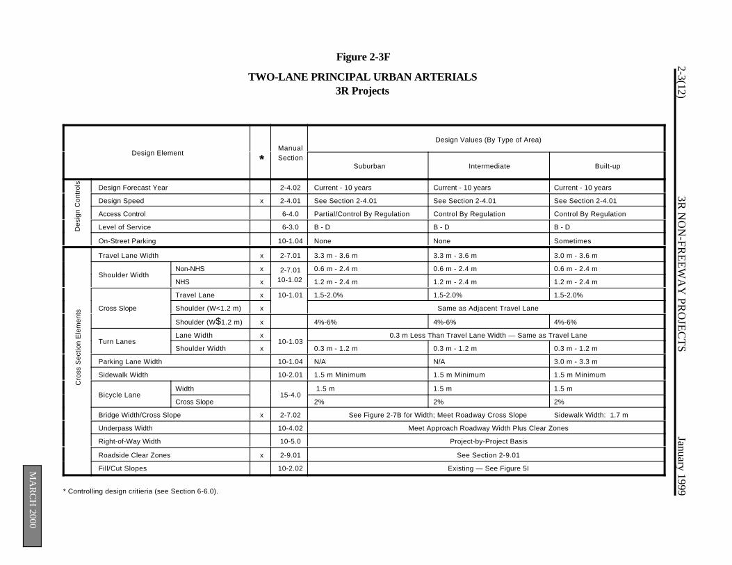
2-3(12)3R
NO
N-FR
EE
WA
Y PR
OJE
CT
SJanuary 1999
MA
RC
H 2000
Des
ign
Con
trol
sC
ross
Sec
tion
Ele
men
ts
Figure 2-3F
TWO-LANE PRINCIPAL URBAN ARTERIALS3R Projects
Design Element*
ManualSection
Design Values (By Type of Area)
Suburban Intermediate Built-up
Design Forecast Year 2-4.02 Current - 10 years Current - 10 years Current - 10 years
Design Speed x 2-4.01 See Section 2-4.01 See Section 2-4.01 See Section 2-4.01
Access Control 6-4.0 Partial/Control By Regulation Control By Regulation Control By Regulation
Level of Service 6-3.0 B - D B - D B - D
On-Street Parking 10-1.04 None None Sometimes
Travel Lane Width x 2-7.01 3.3 m - 3.6 m 3.3 m - 3.6 m 3.0 m - 3.6 m
Shoulder WidthNon-NHS x 2-7.01
10-1.02
0.6 m - 2.4 m 0.6 m - 2.4 m 0.6 m - 2.4 m
NHS x 1.2 m - 2.4 m 1.2 m - 2.4 m 1.2 m - 2.4 m
Cross Slope
Travel Lane x 10-1.01 1.5-2.0% 1.5-2.0% 1.5-2.0%
Shoulder (W<1.2 m) x Same as Adjacent Travel Lane
Shoulder (W$1.2 m) x 4%-6% 4%-6% 4%-6%
Turn LanesLane Width x
10-1.030.3 m Less Than Travel Lane Width — Same as Travel Lane
Shoulder Width x 0.3 m - 1.2 m 0.3 m - 1.2 m 0.3 m - 1.2 m
Parking Lane Width 10-1.04 N/A N/A 3.0 m - 3.3 m
Sidewalk Width 10-2.01 1.5 m Minimum 1.5 m Minimum 1.5 m Minimum
Bicycle LaneWidth
15-4.0 1.5 m 1.5 m 1.5 m
Cross Slope 2% 2% 2%
Bridge Width/Cross Slope x 2-7.02 See Figure 2-7B for Width; Meet Roadway Cross Slope Sidewalk Width: 1.7 m
Underpass Width 10-4.02 Meet Approach Roadway Width Plus Clear Zones
Right-of-Way Width 10-5.0 Project-by-Project Basis
Roadside Clear Zones x 2-9.01 See Section 2-9.01
Fill/Cut Slopes 10-2.02 Existing — See Figure 5I
* Controlling design critieria (see Section 6-6.0).

January 19993R
NO
N-FR
EE
WA
Y PR
OJE
CT
S2-3(13)
Figure 2-3F (Continued)
TWO-LANE PRINCIPAL URBAN ARTERIALS3R Projects
Design Element * ManualSection
Design Values (Based on Design Speed)
90 km/h 80 km/h 70 km/h 60 km/h 50 km/h
Stopping Sight Distance x 7-1.0 135 m - 170 m 115 m - 140 m 95 m - 115 m 75 m - 85 m 60 m - 65 m
Decision Sight Distance
Maneuver7-2.0
U: 360 mSU: 320 m
U: 315 mSU: 275 m
U: 275 mSU: 240 m
U: 235 mSU: 205 m
U: 200 mSU: 160 m
Stop 360 m 300 m 250 m 205 m 160 m
Minimum Radius x 2-5.01/2-5.02 See Section 2-5.01 190 m
(e =4%)130 m(e = 4%)
80 m(e = 4%)
Superelevation Rate
emax 2-5.01/2-5.02
6.0% 6.0% 4.0% 4.0% 4.0%
Rate x See Section 2-5.01 See Figure 8-3C
Horizontal Sight Distance 8-2.04 See Section 8-2.04
Maximum Grade x 2-6.01 8% 9% 9% 10% 11%
Minimum Grade 9-2.03 0.5%
Vertical Curvature (K-values)
Crest 2-6.02 See Section 2-6.02
Sag 2-6.03 21 17 13 10 7
A
lignm
ent E
lem
ents
Minimum Vertical Clearance: Arterial Under...
New HighwayBridge x
9-4.0
5.05 m
Existing HighwayBridge x 4.35 m
Pedestrian Bridge/Overhead Sign x 5.35 m
Minimum Vertical Clearance (Arterial over Railroad) x 9-4.0
Electrified: 6.848 mAll Others: 6.248 m
* Controlling design criteria (see Section 6-6.0).
U: Urban SU: Suburban

2-3(14)3R
NO
N-FR
EE
WA
Y PR
OJE
CT
SJanuary 1999
MA
RC
H 2000
Des
ign
Con
trol
sC
ross
Sec
tion
Ele
men
ts
Figure 2-3G
MINOR URBAN ARTERIALS3R Projects
Design Element*
ManualSection
Design Values (By Type of Area)
Suburban Intermediate Built-up
Design Forecast Year 2-4.02 Current - 10 years Current - 10 years Current - 10 years
Design Speed x 2-4.01 See Section 2-4.01 See Section 2-4.01 See Section 2-4.01
Access Control 6-4.0 Control By Regulation Control By Regulation Control By Regulation
Level of Service 6-3.0 B - D B - D B - D
On-Street Parking 10-1.04 None Sometimes Sometimes
Travel Lane Width x 2-7.01 3.3 m - 3.6 m 3.0 m - 3.6 m 3.0 m - 3.6 m
Shoulder Width
Right (Non-NHS) x2-7.01
10-1.02
0.6 m - 2.4 m 0.6 m - 2.4 m 0.6 m - 2.4 m
Right (NHS) x 1.2 m - 2.4 m 1.2 m - 2.4 m 1.2 m - 2.4 m
Left (All) x 0.6 m - 1.2 m 0.6 m - 1.2 m 0.6 m - 1.2 m
Cross Slope
Travel Lane x 10-1.01 1.5-2.0% for lanes adjacent to crown; 2% for lanes away from crown
Shoulder (W<1.2 m) x10-1.02
Same as Adjacent Travel Lane
Shoulder (W$1.2 m) x 4%-6% 4%-6% 4%-6%
Turn LanesLane Width x
10-1.030.3 m Less Than Travel Lane Width — Same as Travel Lane
Shoulder Width x 0.3 m - 1.2 m 0.3 m - 1.2 m 0.3 m - 1.2 m
Parking Lane Width 10-1.04 N/A 2.7 m - 3.3 m 2.4 m - 3.3 m
Sidewalk Width 10-2.01 1.5 m Minimum 1.5 m Minimum 1.5 m Minimum
Bicycle LaneWidth
15-4.01.5 m 1.5 m 1.5 m
Cross Slope 2% 2% 2%
Bridge Width/Cross Slope x 2-7.02 See Figure 2-7B for Width; Meet Roadway Cross Slope Sidewalk Width: 1.7 m
Underpass Width 10-4.02 Meet Approach Roadway Width Plus Clear Zones
Right-of-Way Width 10-5.0 Project-by-Project Basis
Roadside Clear Zones x 2-9.01 See Section 2-9.01
Fill/Cut Slopes 10-2.02 Existing — See Figure 5I
* Controlling design critieria (see Section 6-6.0).
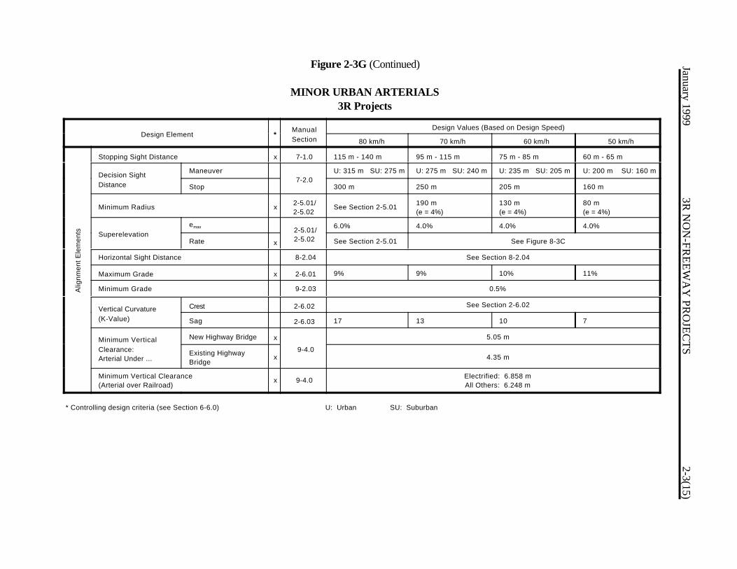
January 19993R
NO
N-FR
EE
WA
Y PR
OJE
CT
S2-3(15)
Alig
nmen
t Ele
men
ts
Figure 2-3G (Continued)
MINOR URBAN ARTERIALS3R Projects
Design Element *ManualSection
Design Values (Based on Design Speed)
80 km/h 70 km/h 60 km/h 50 km/h
Stopping Sight Distance x 7-1.0 115 m - 140 m 95 m - 115 m 75 m - 85 m 60 m - 65 m
Decision SightDistance
Maneuver7-2.0
U: 315 m SU: 275 m U: 275 m SU: 240 m U: 235 m SU: 205 m U: 200 m SU: 160 m
Stop 300 m 250 m 205 m 160 m
Minimum Radius x 2-5.01/2-5.02
See Section 2-5.01 190 m(e = 4%)
130 m(e = 4%)
80 m(e = 4%)
Superelevationemax 2-5.01/
2-5.02
6.0% 4.0% 4.0% 4.0%
Rate x See Section 2-5.01 See Figure 8-3C
Horizontal Sight Distance 8-2.04 See Section 8-2.04
Maximum Grade x 2-6.01 9% 9% 10% 11%
Minimum Grade 9-2.03 0.5%
Vertical Curvature(K-Value)
Crest 2-6.02 See Section 2-6.02
Sag 2-6.03 17 13 10 7
Minimum VerticalClearance:Arterial Under ...
New Highway Bridge x
9-4.0
5.05 m
Existing HighwayBridge
x 4.35 m
Minimum Vertical Clearance(Arterial over Railroad)
x 9-4.0 Electrified: 6.858 mAll Others: 6.248 m
* Controlling design criteria (see Section 6-6.0) U: Urban SU: Suburban

2-3(16)3R
NO
N-FR
EE
WA
Y PR
OJE
CT
SJanuary 1999
MA
RC
H 2000
Des
ign
Con
trol
sC
ross
Sec
tion
Ele
men
tsFigure 2-3H
URBAN COLLECTOR STREETS3R Projects
Design Element*
ManualSection
Design Values (By Type of Area)
Suburban Intermediate Built-up
Design Forecast Year 2-4.02 Current - 10 years Current - 10 years Current - 10 years
Design Speed x 2-4.01 See Section 2-4.01 See Section 2-4.01 See Section 2-4.01
Access Control 6-4.0 Control By Regulation Control By Regulation Control By Regulation
Level of Service 6-3.0 C - D C - D C - D
On-Street Parking 10-1.04 Sometimes Sometimes Sometimes
Travel Lane Width x 2-7.01 3.0 m - 3.6 m 3.0 m - 3.6 m 3.0 m - 3.6 m
Shoulder Width x2-7.01
10-1.020.6 m - 2.4 m 0.6 m - 2.4 m 0.6 m - 2.4 m
Cross Slope
Travel Lane (w/curb) 1.5-3.0% 1.5-3.0% 1.5-3.0%
Travel Lane(w/ocurb)
x
10-1.01
1.5-2.0% for lanes adjacent to crown; 2% for lanes away from crown
Shoulder (W<1.2 m) x Same as Adjacent Travel Lane
Shoulder (W$1.2 m) x 4%-6% 4%-6% 4%-6%
Turn LanesLane Width x
10-1.030.3 m Less Than Travel Lane Width — Same as Travel Lane
Shoulder Width x 0.3 m - 1.2 m 0.3 m - 1.2 m 0.3 m - 1.2 m
Parking Lane Width 10-1.04 2.1 m - 3.0 m 2.1 m - 3.0 m 2.1 m - 3.0 m
Sidewalk Width 10-2.01 1.5 m Minimum 1.5 m Minimum 1.5 m Minimum
Bicycle Lane Width
15-4.01.5 m 1.5 m 1.5 m
Cross Slope 2% 2% 2%
Bridge Width/Cross Slope x 2-7.02 See Figure 2-7B for Width; Meet Roadway Cross Slope Sidewalk Width: 1.7 m
Underpass Width 10-4.02 Meet Approach Roadway Width Plus Clear Zones
Right-of-Way Width 10-5.0 Project-by-Project Basis
Roadside Clear Zones x 2-9.01 See Section 2-9.01
Fill/Cut Slopes 10-2.02 See Figure 5I — Existing
* Controlling design criteria (see Section 6-6.0).
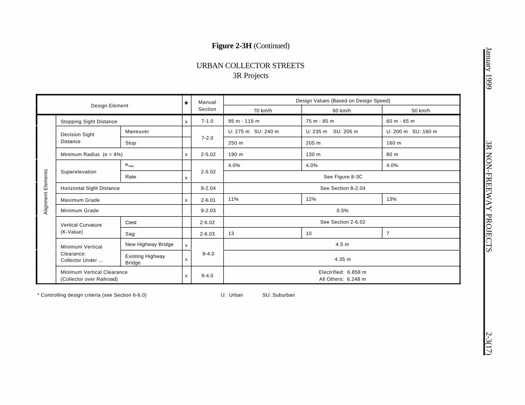
January 19993R
NO
N-FR
EE
WA
Y PR
OJE
CT
S2-3(17)
Alig
nmen
t Ele
men
tsFigure 2-3H (Continued)
URBAN COLLECTOR STREETS3R Projects
Design Element * ManualSection
Design Values (Based on Design Speed)
70 km/h 60 km/h 50 km/h
Stopping Sight Distance x 7-1.0 95 m - 115 m 75 m - 85 m 60 m - 65 m
Decision SightDistance
Maneuver7-2.0
U: 275 m SU: 240 m U: 235 m SU: 205 m U: 200 m SU: 160 m
Stop 250 m 205 m 160 m
Minimum Radius (e = 4%) x 2-5.02 190 m 130 m 80 m
Superelevationemax
2-5.024.0% 4.0% 4.0%
Rate x See Figure 8-3C
Horizontal Sight Distance 8-2.04 See Section 8-2.04
Maximum Grade x 2-6.01 11% 12% 13%
Minimum Grade 9-2.03 0.5%
Vertical Curvature(K-Value)
Crest 2-6.02 See Section 2-6.02
Sag 2-6.03 13 10 7
Minimum VerticalClearance:Collector Under ...
New Highway Bridge x
9-4.0
4.5 m
Existing HighwayBridge
x 4.35 m
Minimum Vertical Clearance(Collector over Railroad)
x 9-4.0Electrified: 6.858 mAll Others: 6.248 m
* Controlling design criteria (see Section 6-6.0) U: Urban SU: Suburban

2-3(18)3R
NO
N-FR
EE
WA
Y PR
OJE
CT
SJanuary 1999
MA
RC
H 2000
Des
ign
Con
trol
sC
ross
Sec
tion
Ele
men
ts
Figure 2-3I
LOCAL URBAN STREETS3R Projects
Design Element*
ManualSection
Design Values (By Type of Area)
Suburban Intermediate Built-up
Design Forecast Year 2-4.02 Current - 10 years Current - 10 years Current - 10 years
Design Speed x 2-4.01 See Section 2-4.01 See Section 2-4.01 See Section 2-4.01
Access Control 6-4.0 Control By Regulation Control By Regulation Control By Regulation
Level of Service 6-3.0 C - D C - D C - D
On-Street Parking 10-1.04 Sometimes Sometimes Sometimes
Travel Lane Width x 2-7.01 3.0 m - 3.3 m 3.0 m - 3.3 m 2.7 m - 3.3 m
Shoulder Width x 2-7.01 0.6 m - 1.2 m 0.6 m - 1.2 m 0.6 m - 1.2 m
Travel Lane x 10-1.01 1.5-2.0% (1.5-3.0% w/curbing) 1.5-2.0% (1.5-3.0% w/curbing) 1.5-2.0% (1.5-3.0% w/curbing)
Shoulder (W < 1.2m)
x10-1.02
Same as Adjacent Travel Lane
Shoulder (W$1.2 m) x 4%-6% 4%-6% 4%-6%
Turn LanesLane Width x
10-1.030.3 m Less Than Travel Lane Width (2.7 m Min.) — Same as Travel Lane
Shoulder Width x 0.3 m - 1.2 m 0.3 m - 1.2 m 0.3 m - 1.2 m
Parking Lane Width 10-1.04 2.1 m - 3.0 m 2.1 m - 3.3 m 2.1 m - 3.3 m
Sidewalk Width 10-2.01 1.5 m Minimum 1.5 m Minimum 1.5 m Minimum
Bicycle Lane Width
15-4.01.5 m 1.5 m 1.5 m
Cross Slope 2% 2% 2%
Bridge Width/Cross Slope x 2-7.02 See Figure 2-7B for Width; Meet Roadway Cross Slope Sidewalk Width: 1.7 m
Underpass Width 10-4.02 Meet Approach Roadway Width Plus Clear Zones
Right-of-Way Width 10-5.0 Project-by-Project Basis
Roadside Clear Zones x 2-9.01 See Section 2-9.01
Fill/Cut Slopes 10-2.02 Existing — See Figure 5I
* Controlling design critieria (see Section 6-6.0).
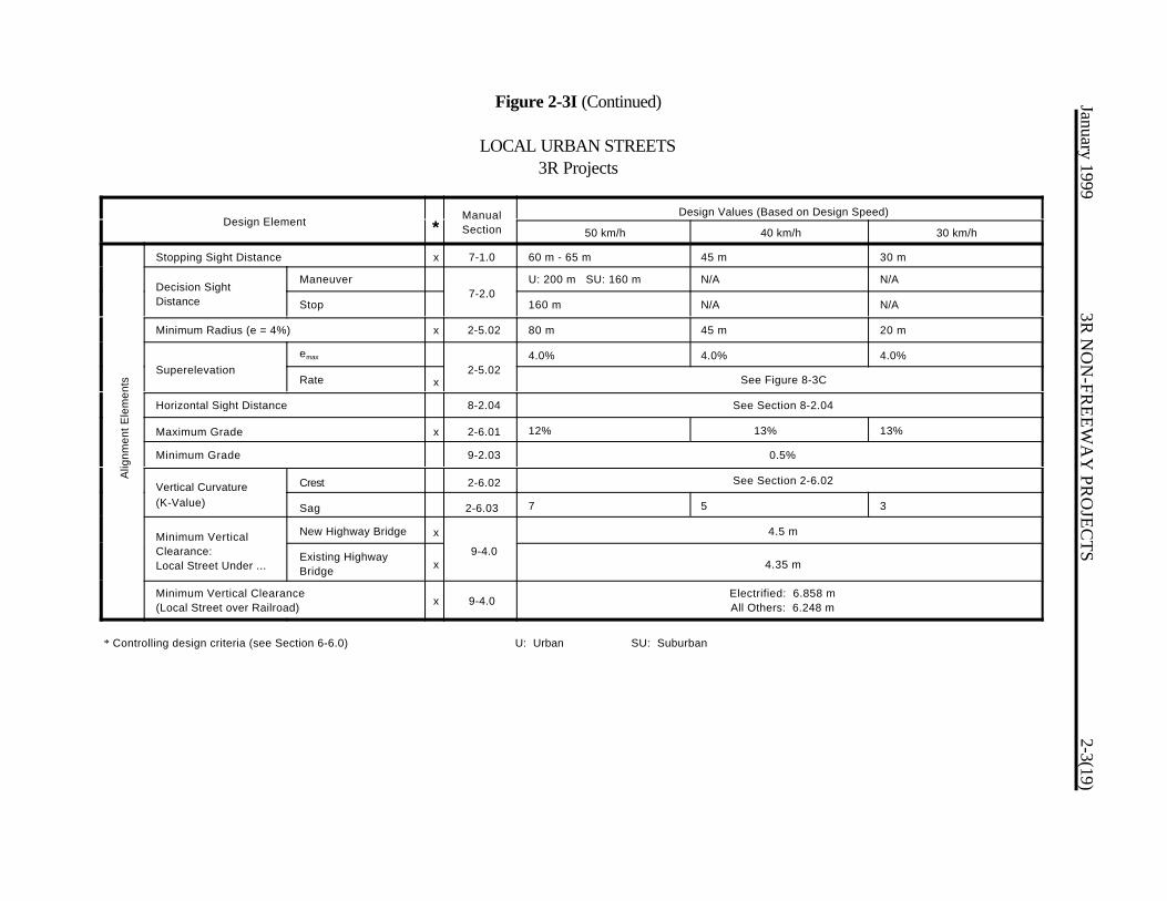
January 19993R
NO
N-FR
EE
WA
Y PR
OJE
CT
S2-3(19)
Alig
nmen
t Ele
men
ts
Figure 2-3I (Continued)
LOCAL URBAN STREETS3R Projects
Design Element *ManualSection
Design Values (Based on Design Speed)
50 km/h 40 km/h 30 km/h
Stopping Sight Distance x 7-1.0 60 m - 65 m 45 m 30 m
Decision SightDistance
Maneuver7-2.0
U: 200 m SU: 160 m N/A N/A
Stop 160 m N/A N/A
Minimum Radius (e = 4%) x 2-5.02 80 m 45 m 20 m
Superelevationemax
2-5.024.0% 4.0% 4.0%
Rate x See Figure 8-3C
Horizontal Sight Distance 8-2.04 See Section 8-2.04
Maximum Grade x 2-6.01 12% 13% 13%
Minimum Grade 9-2.03 0.5%
Vertical Curvature(K-Value)
Crest 2-6.02 See Section 2-6.02
Sag 2-6.03 7 5 3
Minimum VerticalClearance:Local Street Under ...
New Highway Bridge x
9-4.0
4.5 m
Existing HighwayBridge x 4.35 m
Minimum Vertical Clearance(Local Street over Railroad) x 9-4.0
Electrified: 6.858 mAll Others: 6.248 m
* Controlling design criteria (see Section 6-6.0) U: Urban SU: Suburban

2-3(20) 3R NON-FREEWAY PROJECTS January 1999
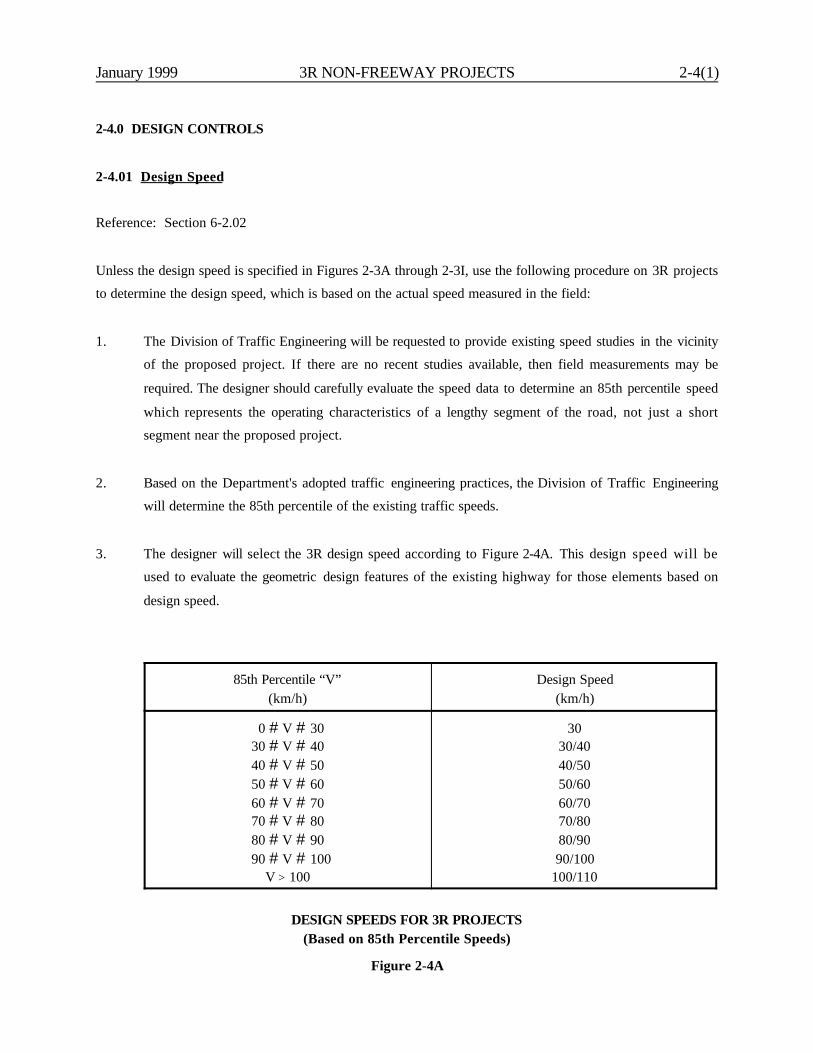
January 1999 3R NON-FREEWAY PROJECTS 2-4(1)
2-4.0 DESIGN CONTROLS
2-4.01 Design Speed
Reference: Section 6-2.02
Unless the design speed is specified in Figures 2-3A through 2-3I, use the following procedure on 3R projects
to determine the design speed, which is based on the actual speed measured in the field:
1. The Division of Traffic Engineering will be requested to provide existing speed studies in the vicinity
of the proposed project. If there are no recent studies available, then field measurements may be
required. The designer should carefully evaluate the speed data to determine an 85th percentile speed
which represents the operating characteristics of a lengthy segment of the road, not just a short
segment near the proposed project.
2. Based on the Department's adopted traffic engineering practices, the Division of Traffic Engineering
will determine the 85th percentile of the existing traffic speeds.
3. The designer will select the 3R design speed according to Figure 2-4A. This design speed will be
used to evaluate the geometric design features of the existing highway for those elements based on
design speed.
85th Percentile “V”(km/h)
Design Speed(km/h)
0 # V # 3030 # V # 4040 # V # 5050 # V # 6060 # V # 7070 # V # 8080 # V # 90
90 # V # 100V > 100
3030/4040/5050/6060/7070/8080/9090/100
100/110
DESIGN SPEEDS FOR 3R PROJECTS(Based on 85th Percentile Speeds)
Figure 2-4A
2-4(2) 3R NON-FREEWAY PROJECTS January 1999
2-4.02 Highway Capacity
Reference: Section 6-3.0
Three major factors determine the results of a capacity analysis. Their specific application to 3R projectsis discussed below:
1. Level of Service (LOS). Figures 2-3A through 2-3I provide the range of LOS criteria for 3Rprojects.
2. Design Volume. The highway facility should be designed to accommodate the LOS for the selectedDHV and/or AADT. The design volume may range from the current traffic volumes to ten yearsbeyond the expected construction completion date.
3. Capacity Analysis. The analytical techniques in the Highway Capacity Manual will be used toconduct the capacity analysis.
2-4.03 Exceptions to Geometric Design Criteria
Reference: Section 6-6.0
The discussion in Section 6-6.0 on exceptions applies equally to the geometric design of 3R projects. Thedesigner will be evaluating the proposed design against the criteria presented in Chapter Two.

January 1999 3R NON-FREEWAY PROJECTS 2-5(1)
2-5.0 HORIZONTAL ALIGNMENT
Chapter Eight discusses horizontal alignment criteria for all highways. These criteria will apply to 3Rprojects, except where discussed in the following sections.
2-5.01 Rural Highways and High-Speed Urban Highways
Reference: Section 8-2.0
Figure 2-5A will be used to determine the design speed of an existing horizontal curve. This should becompared to the 85th percentile speed. In the absence of an adverse accident history, all existing horizontalcurves with a design speed within 25 km/h of the 85th percentile speed are acceptable. No formal designexception is required for horizontal curves within this range; however, it should be documented in theproject files.
Figure 2-5A can be used only to decide if corrective action should be considered. Once the decision hasbeen made to improve the curve, the designer should use the criteria in Figure 8-2A to determine theproper combination of curve radius and superelevation to meet the 3R design speed.
If the existing curve satisfies the above criteria for design speed, the designer will not normally need tocheck other details of the horizontal curve (e.g., superelevation transition length, distribution ofsuperelevation between tangent and curve).
2-5.02 Low-Speed Urban Streets
Reference: Section 8-3.0
Section 8-3.0 discusses horizontal alignment criteria for low-speed urban streets (design speed of 70 km/hand below), and Figure 8-3C can be used to determine the design speed of an existing horizontal curve.Once this is determined, the 3R evaluation of the horizontal curve on a low-speed urban street will besimilar to that for rural highways/high-speed urban highways in Section 2-5.01.
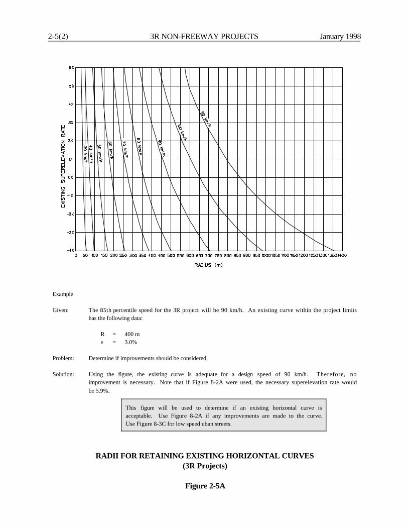
2-5(2) 3R NON-FREEWAY PROJECTS January 1998
This figure will be used to determine if an existing horizontal curve isacceptable. Use Figure 8-2A if any improvements are made to the curve.Use Figure 8-3C for low speed uban streets.
Example
Given: The 85th percentile speed for the 3R project will be 90 km/h. An existing curve within the project limitshas the following data:
R = 400 me = 3.0%
Problem: Determine if improvements should be considered.
Solution: Using the figure, the existing curve is adequate for a design speed of 90 km/h. Therefore, noimprovement is necessary. Note that if Figure 8-2A were used, the necessary superelevation rate wouldbe 5.9%.
RADII FOR RETAINING EXISTING HORIZONTAL CURVES(3R Projects)
Figure 2-5A
January 1999 3R NON-FREEWAY PROJECTS 2-6(1)
2-6.0 VERTICAL ALIGNMENT
2-6.01 Grades
Reference: Section 9-2.0
Figures 2-3A through 2-3I present the Department’s criteria for maximum and minimum grades on 3Rprojects. The maximum grades are 2% steeper than those for new construction/major reconstruction.
2-6.02 Crest Vertical Curves
Reference: Section 9-3.02
Section 9-3.02 presents the Department's criteria for the design of crest vertical curves. This informationwill be used to determine the design speed of an existing crest vertical curve, which will then be comparedto the 85th percentile speed. The following summarizes the 3R design criteria for crest vertical curves:
1. Crest Vertical Curves. In the absence of an adverse accident history, all existing crest verticalcurves with a design speed within 30 km/h of the 85th percentile speed are acceptable. No formaldesign exception is required for crest vertical curves within this range; however, it should bedocumented in the project files.
2. Angle Points. It is acceptable to retain an existing “angle” point (i.e., no vertical curve) of 1.0percent or less.
If the decision is made to flatten the crest vertical curve, the designer should design the reconstructed curveto meet the criteria for new construction/major reconstruction in Section 9-3.02.
2-6.03 Sag Vertical Curves
Reference: Section 9-3.03
Section 9-3.03 presents the Department's criteria for the design of sag vertical curves for new constructionand major reconstruction. These criteria are based on designing the sag to allow the vehicle's headlights toilluminate the pavement for a distance equal to the stopping sight distance for the design speed. For 3Rprojects, the following will apply:
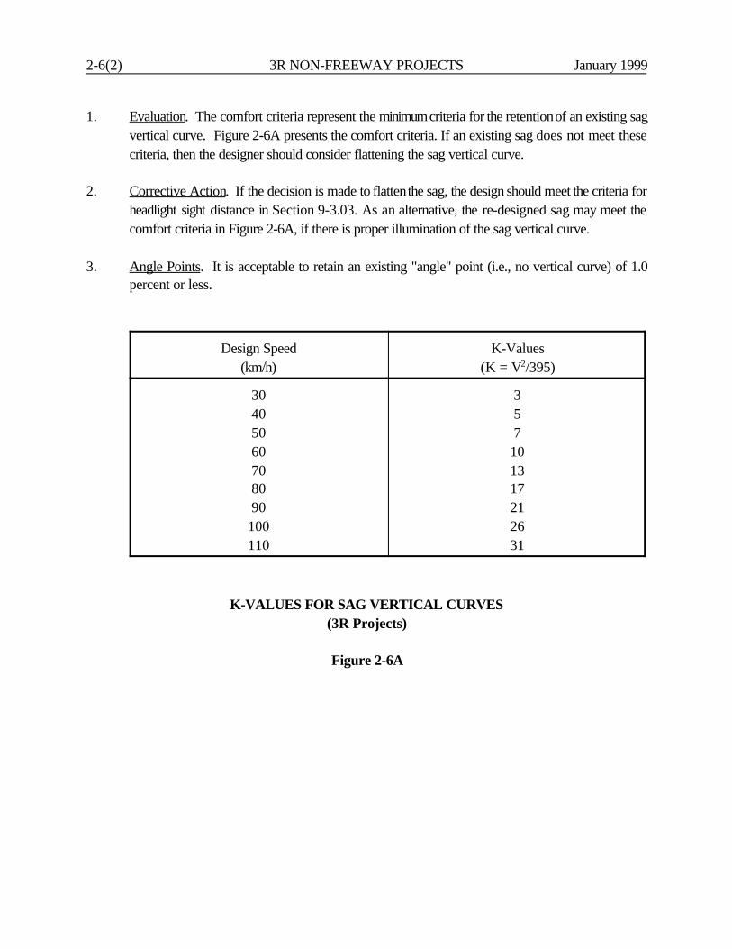
2-6(2) 3R NON-FREEWAY PROJECTS January 1999
1. Evaluation. The comfort criteria represent the minimum criteria for the retention of an existing sagvertical curve. Figure 2-6A presents the comfort criteria. If an existing sag does not meet thesecriteria, then the designer should consider flattening the sag vertical curve.
2. Corrective Action. If the decision is made to flatten the sag, the design should meet the criteria forheadlight sight distance in Section 9-3.03. As an alternative, the re-designed sag may meet thecomfort criteria in Figure 2-6A, if there is proper illumination of the sag vertical curve.
3. Angle Points. It is acceptable to retain an existing "angle" point (i.e., no vertical curve) of 1.0percent or less.
Design Speed(km/h)
K-Values(K = V2/395)
30405060708090100110
357101317212631
K-VALUES FOR SAG VERTICAL CURVES(3R Projects)
Figure 2-6A
January 1999 3R NON-FREEWAY PROJECTS 2-7(1)
2-7.0 CROSS SECTIONS
2-7.01 Widths
Reference: Chapters Four and Five
Chapters Four and Five present the Department's criteria for cross section elements for new constructionand major reconstruction. Figure 2-7A presents the travel lane widths for rural 3R collectors and arterials.The figures in Section 2-3.0 present the shoulder widths for rural 3R projects and present the travel laneand shoulder widths for urban 3R projects. In general, the 3R widths have been established consideringthe minimum acceptable width for the element from an operational and safety perspective; considering whatwill be available for a practical improvement on a "typical" 3R project; and considering that, in general, itis better to improve more kilometers to a lower level than to improve fewer kilometers to a higher level.All of these considerations are consistent with the overall objectives of the Department's 3R program.
2-7.02 Bridges
Reference: Section 10-4.01
2-7.02.01 Bridge Rehabilitation/Reconstruction
A bridge or several bridges may be within the limits of the 3R project. The bridge substructure and/orsuperstructure may be partially or entirely reconstructed as part of the 3R project. If this work includesrehabilitation of the bridge deck, the full approach width, including shoulders, will be carried across thestructure. Note: CGS 13a-86 requires a minimum bridge width of 8.534 m on any two-lane highwaymaintained by the Commissioner, exclusive of any sidewalk width. No exceptions to this criteria willbe allowed on State-maintained highways unless, in the judgment of the Commissioner, a lesserwidth is warranted. The criteria in CGS 13a-86 does not apply to bridges on highways maintainedby a municipality.
If a bridge rehabilitation/reconstruction project will involve the replacement of the bridge deck or more tothe superstructure, then Comment #’s 2, 3 and 4 on Narrow Bridges, Bridge Rails and ApproachTransitions in Section 2-7.02.02 also apply.

2-7(2) 3R NON-FREEWAY PROJECTS January 1999
Design YearAADT
FunctionalClass
Design Speed(km/h)
Lane Width
T $ 10% T < 10%
1 - 400Collector/
Arterial
# 70 3.0 m 2.7 m
$ 80 3.0 m 3.0 m
400 - 750Collector/
Arterial
#70 3.0 m 2.7 m
$ 80 3. 0 m 3.0 m
750 - 1500
Collector#70 3.3 m 3.0 m
$80 3.3 m 3.3 m
Arterial# 70 3.3 m 3.0 m
$ 80 3.6 m 3.3 m
1500 - 2000Collector/
Arterial
# 70 3.3 m 3.0 m
$ 80 3.6 m 3.3 m
> 2000Collector/
ArterialAll 3.6 m 3.6 m
Note: T = Trucks
TRAVEL LANE WIDTHS(Rural 3R Projects)
Figure 2-7A
January 1999 3R NON-FREEWAY PROJECTS 2-7(3)
2-7.02.02 Bridges to Remain in Place
If an existing bridge is structurally sound and if it meets the Department's design loading structural capacity,it is unlikely to be cost effective to improve the geometrics of the bridge. However, the geometricdeficiencies may be severe, and/or there may be an adverse accident experience at the bridge. Thefollowing will apply to all bridges to remain in place with no proposed improvements:
1. Width. The width of the existing bridge should be evaluated against the criteria in Figure 2-7B. Ifthe existing bridge does not meet these criteria, it should be evaluated for widening, including areview of the accident experience at the bridge.
2. Narrow Bridges. All bridges which are narrower than the approach roadway width (includingshoulders) should be evaluated for special narrow bridge treatments. At a minimum, the signing andpavement markings must meet the criteria of the MUTCD. In addition, NCHRP 203 Safety atNarrow Bridge Sites provides criteria specifically for narrow bridges (e.g., special pavementmarkings). The designer, in coordination with the Division of Traffic Engineering, should evaluatethe value of these additional treatments at the bridge site.
3. Bridge Rails. All existing bridge rails on the project should be evaluated to determine if they arestructurally adequate and meet the Department’s current safety performance criteria.
4. Approach Guide Rail Transitions. The approaching guide rail transitions will be evaluated todetermine if they meet the Department's current criteria. If the transitions do not, they will beupgraded. The Department's latest standard sheets will be used to make these determinations.
2-7.03 Climbing Lanes
Reference: Section 9-2.0
The design criteria in Section 9-2.0 will apply to existing or proposed climbing lanes within the limits of 3Rprojects; however, for non-freeway projects, the following criteria are acceptable:
1. Lane Width. The minimum width of the climbing lane will be 3.3 m.
2. Shoulder Width. The minimum width of the shoulder adjacent to the climbing lane will be 1.2 m.
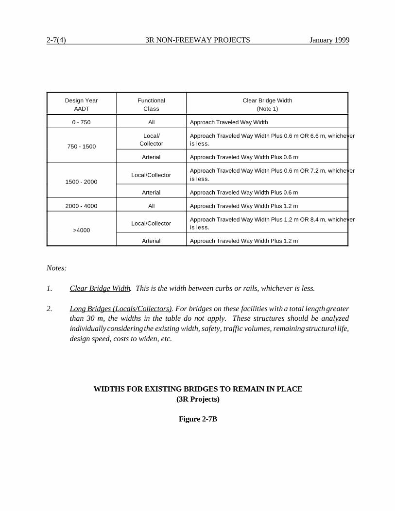
2-7(4) 3R NON-FREEWAY PROJECTS January 1999
Design YearAADT
FunctionalClass
Clear Bridge Width(Note 1)
0 - 750 All Approach Traveled Way Width
750 - 1500
Local/Collector
Approach Traveled Way Width Plus 0.6 m OR 6.6 m, whicheveris less.
Arterial Approach Traveled Way Width Plus 0.6 m
1500 - 2000Local/Collector
Approach Traveled Way Width Plus 0.6 m OR 7.2 m, whicheveris less.
Arterial Approach Traveled Way Width Plus 0.6 m
2000 - 4000 All Approach Traveled Way Width Plus 1.2 m
>4000Local/Collector
Approach Traveled Way Width Plus 1.2 m OR 8.4 m, whicheveris less.
Arterial Approach Traveled Way Width Plus 1.2 m
Notes:
1. Clear Bridge Width. This is the width between curbs or rails, whichever is less.
2. Long Bridges (Locals/Collectors). For bridges on these facilities with a total length greaterthan 30 m, the widths in the table do not apply. These structures should be analyzedindividually considering the existing width, safety, traffic volumes, remaining structural life,design speed, costs to widen, etc.
WIDTHS FOR EXISTING BRIDGES TO REMAIN IN PLACE(3R Projects)
Figure 2-7B

January 1999 3R NON-FREEWAY PROJECTS 2-7(5)
2-7.04 Other Cross Section Elements
Reference: Chapters Four, Five and Ten
These chapters provide the Department's criteria and details for many other cross section elements,including:
1. location and type of parking lanes,2. warrants for and types of curbs,3. warrants for and design of sidewalks,4. slope rounding,5. roadside ditches,6. median type, and7. fill and cut slopes.
The designer should evaluate the cross section of the existing highway or street and, as part of the 3Rproject, should make any improvements which are considered cost effective. Some of the designinformation in Chapter Ten applies directly to 3R projects (e.g., warrants for curbs and sidewalks); someof the design information will only apply if practical (e.g., slope rounding).

2-7(6) 3R NON-FREEWAY PROJECTS January 1999
January 1999 3R NON-FREEWAY PROJECTS 2-8(1)
2-8.0 SPECIAL DESIGN ELEMENTS
2-8.01 General
Reference: Chapter Fifteen
Chapter Fifteen provides the Department's criteria and design details for many special design elements. Thedesigner should review this chapter to determine if these criteria apply to the 3R project. For example,Section 15-5.0 presents information on landscaping. Aesthetics can play a significant role in the communityacceptance of a roadway improvement. Designers should aim to preserve or restore as much of theexisting landscape as practical. Chapter Fifteen provides the necessary tools and references that shouldbe considered to maintain or improve the visual quality of the roadway.
2-8.02 Traffic Calming
Traffic calming measures (TCM) consist of a variety of techniques and treatments designed to mitigate theimpacts of vehicular travel. Traffic calming is typically limited to municipal streets but may be consideredon State-maintained facilities off the NHS. TCMs typically refer to an assortment of physical featuresplaced within the limits of the roadway environment including; but not limited to the following:
1. intersection diverters,2. roundabouts,3. channelization,4. speed humps,5. speed tables,6. street narrowing,7. angle point/chicanes,8. driveway links,9. gateway/perimeter treatments, and10. street closure.
Municipalities that have developed TCM guidelines may explore traffic calming strategies on a project-by-project basis. An effective traffic calming strategy may integrate more than one TCM into a comprehensivetraffic calming program for the study area. For additional information on traffic calming strategies andmeasures, see the following publications:
2-8(2) 3R NON-FREEWAY PROJECTS January 1999
1. Traffic Calming In Practice, ITE;
2. State of the Art: Residential Traffic Management, FHWA;
3. State-of-the-Art Design of Roundabouts, TRB;
4. Take Back Your Streets - How to Protect Communities from Asphalt and Traffic,Conservation Law Foundation;
5. Residential Street Design and Traffic Control, ITE;
6. Guidelines for the Design and Application of Speed Humps, A Recommended Practice, ITE;
7. Roundabouts, Diverts and Humps, ITE; and
8. Effective Utilization of Street Width on Urban Arterials, ITE;
January 1999 3R NON-FREEWAY PROJECTS 2-9(1)
2-9.0 ROADSIDE SAFETY
2-9.01 Clear Zones
Reference: Section 13-2.0
2-9.01.01 Basic 3R Criteria
Section 13-2.0 presents the Department's criteria for roadside clear zones on new construction and majorreconstruction projects. The clear zone criteria for 3R projects will be as follows:
1. The designer should make every reasonable effort to provide a clear zone equal to the criteria inSection 13-2.0.
2. For 3R projects, the criteria in Section 13-2.0 may be modified as follows: On urban and ruralcollector and local roads where the 3R design speed is 70 km/h and below, the minimum clearzone should be 3.0 m. If practical, the clear zone should be increased where the side slope is 1:6or steeper. The criteria in Section 13-2.0 can be used to determine the applicable adjustments.
3. It will often be impractical on 3R projects to obtain additional right-of-way specifically to meet thecriteria in Section 13-2.0 or, sometimes, even the minimum clear zone criteria from #2 above.Therefore, for the purpose of deciding when a design exception is necessary, the proposed clearzone will be measured against Section 13-2.0, as modified by # 2 above, or against the existingright-of-way, whichever is less. If the clear zone used in design is the existing right-of-way line andif existing utility poles are as near as practical to the right-of-way line, then the utility poles canintrude into the clear zone without the need for a design exception.
Attempting to achieve a roadside clear zone on a 3R project can cause significant problems. The roadsideenvironment is typically cluttered with any number of natural and man-made obstacles. To remove orrelocate these obstacles can present formidable problems and public opposition, and it can be very costly.On the other hand, the designer cannot ignore the consequences to a run-off-the-road vehicle. Therefore,the designer must exercise considerable judgment when determining the appropriate clear zone on the 3Rproject. The designer should consider the following:
1. Accident Data. The designer should review the accident data to estimate the extent of the roadsidesafety problem. In particular, there may be sites where clusters of run-off-the-road accidents haveoccurred.
2-9(2) 3R NON-FREEWAY PROJECTS January 1999
2. Utilities. Utility poles are a common roadside obstacle on 3R projects. Relocation is mandatorywhen the utility poles physically interfere with construction. Relocations for safety benefits must beevaluated on a project-by-project basis. Poles should be located as near as practical to the right-of-way line. In restricted right-of-way areas, every effort should be made to provide the clear zoneused in design. The use of armless single-pole construction with vertical configuration of wires andcables and/or other special construction, as may be appropriate, should be considered. In urbanareas, the designer should also consider burying the utilities underground when relocation isimpractical.
3. Application. The designer may consider a selective application of the roadside clear zone criteria.Along some sections of highway, it may be practical to provide the clear zone criteria from Section13-2.0 while, along other sections, it may be impractical. In addition, some obstacles will be morehazardous than others. Judgment will be necessary for the application of the clear zone criteria.
4. Public. Public acceptance of widened clear zones can be a significant issue, especially when theremoval of trees is being considered. The designer must judge the community impact andsubjectively factor this into the decision-making process.
5. Safety Appurtenances. Installing guide rail or crash cushions is an alternative to providing a widerclear zone. Section 13-3.0 presents warrants for guide rail, and Section 13-7.0 presents warrantsfor crash cushions. However, this can lead to lengthy runs of guide rail along the roadside. Thedesigner should realize that the guide rail warrants are based on the relative severity betweenhazard and guide rail; they do not address the question of whether or not a guide rail installationis cost-effective. Therefore, on 3R projects, the designer must judge whether or not guide railshould be installed to shield a hazard within the clear zone. See Section 2-9.02 for morediscussion.
2-9.01.02 Rock Removal
Because of the often considerable expense to remove rock to meet the Department’s roadside clear zonecriteria, the Department has adopted a policy specifically for this design element. If the costs andassociated impacts with removing rock to meet the 3R clear zone criteria are insignificant, the designershould implement the improvement. If, however, there are negative impacts and/or the costs are significant,the designer should evaluate the following factors:
1. Project Scope. Based on the overall project objectives, the designer should judge if the potentialbenefits and costs of the rock removal are consistent with the project scope of work.
January 1999 3R NON-FREEWAY PROJECTS 2-9(3)
2. Accident Data. The designer should review the accident data along the 3R project route to identifythe specific roadside hazards related to the presence of rock.
3. Other Benefits. The rock removal may generate benefits other than those for roadside safety.These include:
a. improving intersection sight distance;b. improving sight distance around horizontal curves; orc. improving any rock stability, ground water and/or icing problems.
Any additional benefits should be considered when determining the extent of rock removal.
4. Alternative Improvements. Where the designer determines that the existing rock presents asignificant roadside hazard, the designer should consider alternative improvements to rock removal.These include:
a. installing a half-section concrete barrier or guide rail, and
b. providing a positive slope (with rounding at its toe) up to the face of the rock (1:4 orsteeper) to provide limited vehicular redirection.
5. Application. If rock is within the clear zone and more than 5.5 m from the edge of traveled way,the ConnDOT Design Exception Committee will review the case and will either:
a. determine that rock removal is appropriate because of its accident potential, orb. grant a design exception of the clear zone criteria.
Designers should also document whether or not the rock is in such a condition that it imperils thetraveling public because of flaking, falling or icing conditions, and they should evaluate the need forroadside barrier protection. This should be documented in the project file and verification soughtfrom the Design Exception Committee.
2-9.02 Safety Appurtenances
Reference: Chapter Thirteen
During the design of a 3R project, all existing safety appurtenances should be examined to determine if theymeet the Department’s current safety performance and design criteria. This includes guide rail, medianbarriers, crash cushions, sign supports, luminaire supports, etc. Normally, all existing safety appurtenances
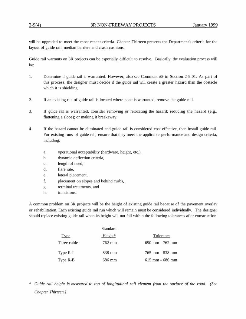
2-9(4) 3R NON-FREEWAY PROJECTS January 1999
will be upgraded to meet the most recent criteria. Chapter Thirteen presents the Department's criteria for thelayout of guide rail, median barriers and crash cushions.
Guide rail warrants on 3R projects can be especially difficult to resolve. Basically, the evaluation process willbe:
1. Determine if guide rail is warranted. However, also see Comment #5 in Section 2-9.01. As part ofthis process, the designer must decide if the guide rail will create a greater hazard than the obstaclewhich it is shielding.
2. If an existing run of guide rail is located where none is warranted, remove the guide rail.
3. If guide rail is warranted, consider removing or relocating the hazard; reducing the hazard (e.g.,flattening a slope); or making it breakaway.
4. If the hazard cannot be eliminated and guide rail is considered cost effective, then install guide rail.For existing runs of guide rail, ensure that they meet the applicable performance and design criteria,including:
a. operational acceptability (hardware, height, etc.),b. dynamic deflection criteria,c. length of need,d. flare rate,e. lateral placement,f. placement on slopes and behind curbs,g. terminal treatments, andh. transitions.
A common problem on 3R projects will be the height of existing guide rail because of the pavement overlayor rehabilitation. Each existing guide rail run which will remain must be considered individually. The designershould replace existing guide rail when its height will not fall within the following tolerances after construction:
Standard
Type Height* Tolerance
Three cable 762 mm 690 mm - 762 mm
Type R-I 838 mm 765 mm - 838 mm
Type R-B 686 mm 615 mm - 686 mm
* Guide rail height is measured to top of longitudinal rail element from the surface of the road. (See
Chapter Thirteen.)
January 1999 3R NON-FREEWAY PROJECTS 2-10(1)
2-10.0 INTERSECTIONS AT-GRADE
Reference: Chapter Eleven
Chapter Eleven provides criteria for the detailed design of intersections at-grade. Where practical, these criteria
apply to 3R projects and should be implemented. The following sections indicate areas where modifications to
the intersection criteria may be made for 3R projects.
2-10.01 Intersection Sight Distance
Reference: Section 11-2.0
The criteria in Section 11-2.0 on intersection sight distance will apply to 3R projects.
2-10.02 Turning Radii
Reference: Section 11-3.0
Section 11-3.0 presents criteria for the selection of a design vehicle, for acceptable encroachment, and for
turning radii criteria at intersections. Where practical, these criteria should be met on 3R projects and, typically,
this is practical in rural areas. However, in urban areas space limitations and existing curb radii have a significant
impact on selecting a practical design for right-turning vehicles. The designer should consider the following when
determining the appropriate right-turn treatment for urban intersections on 3R projects:
1. Simple radii of 4.5 m to 7.5 m are adequate for passenger vehicles. These radii may be retained on 3R
projects on existing streets and arterials at:
a. intersections with minor roads where very few trucks will be turning;
b. intersections where the encroachment of SU and semitrailer vehicles onto adjacent lanes is
acceptable; and
c. intersections where a parking lane is present, and it is restricted a sufficient distance from the
intersection, and it is used as a parking lane throughout the day.
2. Where practical, simple radii of 9 m or simple radii with tapers (for an SU design vehicle) should be used
at all major intersections and at all minor intersections with some truck turning volumes.
2-10(2) 3R NON-FREEWAY PROJECTS January 1999
3. At intersections where semitrailer combinations and buses turn frequently, a simple radius of 12 m
or more should be provided. Preferably, the designer will use a radius with taper offsets for the
selected design vehicle.
2-10.03 Auxiliary Turning Lanes
Reference: Section 11-5.0
Section 11-5.0 presents warrants for right- and left-turn lanes. These criteria apply to 3R projects. Section
11-5.0 also presents design details for auxiliary turning lanes, and these should be met for 3R projects.
However, in urban areas these criteria may be impractical because of restricted conditions. In these cases,
the designer will provide the best design practical for the existing field conditions.
2-10.04 Driveway Design
Reference: Section 11-8.0
The criteria in Section 11-8.0 on driveway design will apply to 3R projects.

January 1999 3R NON-FREEWAY PROJECTS 2-11(1)
2-11.0 REFERENCES
1. A Policy on Geometric Design of Highways and Streets, AASHTO, 1994.
2. Special Report 214 Designing Safer Roads; Practices for Resurfacing, Restoration and
Rehabilitation, TRB, 1987.
3. Technical Advisory T5040.28 “Developing Geometric Design Criteria and Processes for Non-
Freeway RRR Projects,” FHWA, 1988.
4. Preserving Connecticut’s Scenic Roads, Corridor Management Handbook, ConnDOT.
5. Roxbury Scenic Corridor Management Plan, Routes 67 and 317, ConnDOT.
6. Route 7 Scenic Corridor Management Plan, towns of Kent, Cornwall and Sharon,
ConnDOT.
7. Sharon Scenic Corridor Management Plan, Routes 4 and 41, ConnDOT.

2-11(2) 3R NON-FREEWAY PROJECTS January 1999
January 1999 4R FREEWAY PROJECTS 3-i
Chapter Three
GEOMETRIC DESIGN OF EXISTING HIGHWAYS(4R Freeway Projects)(Spot Improvements)
Table of Contents
Page
3-1.0 4R FREEWAY PROJECTS . . . . . . . . . . . . . . . . . . . . . . . . . . . . . . . . . . . . . . . . . . . . 3-1(1)
3-1.01 Background . . . . . . . . . . . . . . . . . . . . . . . . . . . . . . . . . . . . . . . . . . . . . . . . 3-1(1)3-1.02 Objectives . . . . . . . . . . . . . . . . . . . . . . . . . . . . . . . . . . . . . . . . . . . . . . . . . 3-1(2)3-1.03 Approach . . . . . . . . . . . . . . . . . . . . . . . . . . . . . . . . . . . . . . . . . . . . . . . . . 3-1(2)
3-1.04 Geometric Design of 4R Freeway Projects . . . . . . . . . . . . . . . . . . . . . . . . . 3-1(3)
3-1.04.01 Design Speed . . . . . . . . . . . . . . . . . . . . . . . . . . . . . . . . . . 3-1(3)3-1.04.02 Traffic Volumes . . . . . . . . . . . . . . . . . . . . . . . . . . . . . . . . . 3-1(4)3-1.04.03 Vertical Clearances . . . . . . . . . . . . . . . . . . . . . . . . . . . . . . 3-1(4)3-1.04.04 Bridges . . . . . . . . . . . . . . . . . . . . . . . . . . . . . . . . . . . . . . . 3-1(4)3-1.04.05 Safety Appurtenances . . . . . . . . . . . . . . . . . . . . . . . . . . . . 3-1(6)3-1.04.06 Interchanges . . . . . . . . . . . . . . . . . . . . . . . . . . . . . . . . . . . . 3-1(6)
3-2.0 SPOT IMPROVEMENTS (Non-Freeways) . . . . . . . . . . . . . . . . . . . . . . . . . . . . . . . . 3-2(1)
3-2.01 Objectives . . . . . . . . . . . . . . . . . . . . . . . . . . . . . . . . . . . . . . . . . . . . . . . . . 3-2(1) 3-2.02 Approach . . . . . . . . . . . . . . . . . . . . . . . . . . . . . . . . . . . . . . . . . . . . . . . . . . 3-2(2)
3-2.03 Geometric Design of Highway Bridge Replacement/Rehabilitation Program (HBRRP) Projects . . . . . . . . . . . . . . . . . . . . . . . . . 3-2(3)
3-2.04 Design Procedures for Local Bridge Projects . . . . . . . . . . . . . . . . . . . . . . . 3-2(4)
3-2.04.01 Scope . . . . . . . . . . . . . . . . . . . . . . . . . . . . . . . . . . . . . . . . . . . 3-2(4)3-2.04.02 Applicability . . . . . . . . . . . . . . . . . . . . . . . . . . . . . . . . . . . . . . . 3-2(4)3-2.04.03 Implementation . . . . . . . . . . . . . . . . . . . . . . . . . . . . . . . . . . . . . 3-2(4)3-2.04.04 Procedures . . . . . . . . . . . . . . . . . . . . . . . . . . . . . . . . . . . . . . . 3-2(5)

3-ii 4R FREEWAY PROJECTS January 1999
January 1999 4R FREEWAY PROJECTS 3-1(1)
Chapter Three
GEOMETRIC DESIGN OF EXISTING HIGHWAYS(4R Freeway Projects) (Spot Improvements)
Chapter Three presents the Department’s criteria for the geometric design of existing highways for thefollowing project types:
1. 4R freeway projects, and2. spot improvements on non-freeways.
For projects on the Merritt Parkway, the geometric design criteria will be determined on a case-by-casebasis.
3-1.0 4R FREEWAY PROJECTS
3-1.01 Background
The Department began construction of its freeway system in the 1950's and, today, the Connecticut systemis nearing completion. The freeway system has introduced a level of mobility and safety for the travelingpublic which was unattainable without its special features, such as full control of access, wide roadwaywidths and high design speeds. In the past few decades, this system has carried traffic volumes in far greaterproportion than its kilometers within the State.
The freeway system requires periodic repair and upgrading which exceeds the limits of normal maintenance.In general, these capital improvements are referred to as 4R freeway projects (resurfacing, restoration,rehabilitation and reconstruction), which applies to any project on an existing freeway. As with non-freeway3R projects, it is often impractical to fully apply new construction criteria to 4R projects without somequalifications. Therefore, the geometric design of 4R freeway projects requires special designconsiderations which are discussed in the following sections.
3-1(2) 4R FREEWAY PROJECTS January 1999
3-1.02 Objectives
The objective of a 4R freeway project is, within practical limits, to return the freeway to its original levelof serviceability or to improve its serviceability to meet current and future demands. This objective appliesto all aspects of the freeway's serviceability, including:
1. structural adequacy,2. drainage,3. level of service for the traffic flow,4. geometric design,5. roadside safety, and6. traffic control.
3-1.03 Approach
4R freeway projects are most often initiated to make a specific improvement to the freeway. Therefore,the Department's approach to the geometric design of 4R freeway projects is to selectively evaluate andimprove the existing geometrics. The 4R approach is summarized as follows:
1. Nature of Improvement. Identify the specific improvement intended for the 4R project. Forexample, geometric improvements might include:
a. add through lanes to improve the level of service,b. upgrade roadside safety,c. increase the length of one or more acceleration lanes at an interchange,d. widen an existing bridge as part of a bridge rehabilitation project,e. eliminate a weaving area at an interchange, and/orf. resurfacing.
2. Numerical Criteria. Apply the Department's new construction criteria specifically to the geometricdesign element which is improved, unless it is otherwise addressed in this chapter for 4R projects.The new construction criteria are presented in Chapters Four and Five. Chapter Ten discussescross sections; Chapter Thirteen discusses roadside safety; and Chapter Twelve presentsgeometric design criteria for interchanges.
3. Secondary Impacts. Identify and evaluate any secondary impacts which may be precipitated bythe freeway improvement. For example:
January 1999 4R FREEWAY PROJECTS 3-1(3)
a. The installation of a concrete median barrier may restrict horizontal sight distance.
b. The addition of through lanes on the outside may reduce the available roadside clear zoneto below the Department's allowable criteria.
c. A pavement overlay may require the adjustment of guide rail height or reduce the verticalclearance.
4. Other Improvements. Identify other geometric design deficiencies within the project limits. Thedesigner will exercise his/her judgment when determining any other improvements which can bepractically corrected without exceeding the intended project scope of work. For example, whenpavement is being constructed to improve acceleration lanes, it may be reasonable to constructpavement to improve deficient shoulders at the same time. Where a design feature can be improvedfor a portion of the project, these improvements should be incorporated.
5. Exceptions. The discussion in Section 6-6.0 on design exceptions applies equally to the geometricdesign of 4R freeway projects. However, it will only apply to the geometric design of the specificfreeway improvement which resulted in project initiation, and it will also apply to any secondaryimpacts which may result from the improvement.
3-1.04 Geometric Design of 4R Freeway Projects
As stated in Section 3-1.03, the Department's design criteria for new construction also applies to 4Rfreeway projects. However, the designer must still make certain decisions, and there is some flexibility thatcan be applied. These are discussed in the following sections.
3-1.04.01 Design Speed
Chapters Four and Five present the Department's criteria for selecting the design speed for new freewayconstruction. These apply to 4R projects at a minimum. However, the designer may judge that these designspeeds are less than the 85th percentile speeds for the project under design. Therefore, the designer hasthe option of requesting a speed study from the Division of Traffic Engineering to determine the 85thpercentile speed on the existing freeway. The designer should follow the procedure in Section 2-4.0 forthis determination.
3-1(4) 4R FREEWAY PROJECTS January 1999
3-1.04.02 Traffic Volumes
Some design elements on 4R freeway projects will require the selection of the DHV (e.g., level of service)or AADT (e.g., roadside clear zones). The freeway will be designed to meet the geometric design criteriafor traffic volumes determined for 10 to 20 years beyond the expected construction completion date.
3-1.04.03 Vertical Clearances
The minimum vertical clearance for freeways passing beneath an existing bridge to remain in place shouldbe 4.9 m over the entire roadway width, including auxiliary lanes and shoulders. (Note: Departmentpractice is to post a "low-clearance" sign on structures with vertical clearances less than 4.35 m.)
3-1.04.04 Bridges
The following discusses the Department's design criteria for bridges on 4R freeway projects.
1. Bridges to Remain in Place. A 4R project may be primarily intended, for example, to improve thepavement condition over several kilometers. A bridge or several bridges may be within the limitsof the 4R project. Desirably, the bridge widths will equal the full approach roadway width,including shoulders. However, this may not be the case. If the existing bridge is structurally soundand if it meets the Department's design loading structural capacity, it is unlikely to be cost effectiveto improve the geometrics of the bridge. However, the geometric deficiencies may be severe,and/or there may be an adverse accident experience at the bridge. In this case, it may be warrantedto widen the bridge as part of the 4R project.
If a bridge remains in place, its minimum width must be equal to the approach traveled way +3.0m (right shoulder) +1.1 m (left shoulder); otherwise, a design exception will be necessary. Inaddition, existing bridge rails on the project should be evaluated to determine if they meet theDepartment’s current safety performance criteria.
2. Bridge Replacement/Rehabilitation. 4R freeway projects will often include bridge replacements orbridge rehabilitation and, in some cases, this will be the entire project scope of work. The followingwill apply to the geometric design of these projects:
a. Horizontal and Vertical Alignment. An existing bridge may have an alignment which doesnot meet the Department's current criteria. For bridge replacement projects, the designer
January 1999 4R FREEWAY PROJECTS 3-1(5)
should evaluate the practicality of realigning the bridge to meet the applicable alignment cri-teria for new construction. For bridge rehabilitation projects, it is unlikely to be costeffective to realign the bridge to correct any alignment deficiencies.
b. Width. The bridge width should equal the full approach roadway width, includingshoulders, as determined by the criteria in Chapters Four and Five for the most likely levelof future highway improvement on the approaches. If practical, this decision should bebased on a capacity analysis for the selected DHV at the selected level of service. Thisanalysis could determine the need for additional travel lanes and/or the need for widershoulders. For example, if the predicted volume of trucks exceeds 250 DDHV, the futureshoulder width on the approach should be 3.6 m. Because freeway bridges representmajor economic investments with lengthy design lives, it may be warranted to provide thewider widths as part of a bridge replacement or rehabilitation project.
As another example, a capacity analysis may indicate the need for an additional throughlane to meet the level-of-service criteria for the design year. The decision may be made towiden the bridge as part of the replacement/rehabilitation project. Until the roadwayapproach is widened, it may be necessary to indicate with pavement markings that theadditional width on the bridge cannot be used by through traffic.
c. Length. The length of the freeway bridge determines the width of the underpass for thefacility passing beneath the freeway. Therefore, if practical, the freeway bridge should belong enough to accommodate any likely future widening of the underpassing roadway. Thismay involve an assessment of the potential for further development in the general vicinityof the underpass. The Bureau of Planning should be consulted for its traffic projections.
d. Bridge Rails. All existing bridge rails on the project should be evaluated to determine if theyare structurally adequate and meet the Department’s current safety performance criteria.
e. Approach Guide Rail Transitions. The approaching guide rail transitions will be evaluatedto determine if they meet the Department's current criteria. If the transitions do not, theywill be upgraded. The Department's latest standard sheets will be used to make thesedeterminations.

3-1(6) 4R FREEWAY PROJECTS January 1999
3-1.04.05 Safety AppurtenancesOne of the objectives of a 4R freeway project may be to upgrade roadside safety along the freeway. Guiderail warrants and design can present difficult problems (e.g., guide rail height). The discussion in Section2-9.0 on 3R non-freeway projects also applies to safety appurtenances on 4R projects.
3-1.04.06 Interchanges
A 4R freeway project may include proposed work on a freeway interchange. The work may be torehabilitate the entire interchange or to make only selective improvements to the interchange geometrics.Chapter Twelve will be used to design the interchange element.
January 1999 SPOT IMPROVEMENTS 3-2(1)
3-2.0 SPOT IMPROVEMENTS (Non-Freeways)
3-2.01 Objectives
Spot improvements are intended to correct an identified deficiency at an isolated location on non-freeways.Occasionally, more than one location is included in a project for design or construction purposes. Thisproject scope of work is consistent with the Department's responsibility to provide a safe drivingenvironment for the motoring public which is free of unexpected demands on the driver. Experience hasdemonstrated the benefits of improving relatively short roadway sections or spot locations with recognizedgeometric deficiencies to at least a level consistent with the adjacent highway sections. This will providedrivers with a facility that is consistent with the principles of driver expectancy.
The deficiency which the spot improvement will correct may be related to structural, geometric, safety,drainage or traffic control problems. These projects are not intended to provide a general upgrading of thehighway, as are projects categorized as new construction, major reconstruction or 3R. For these reasons,a flexible approach is necessary to determine the appropriate geometric design criteria which will apply tothe spot improvement.
Spot improvement projects may also be affected by special criteria which may apply to a particular fundingcategory. Two examples are:
1. Safety Projects. These projects are intended to provide cost-effective improvements to sitesidentified as having an unusually high number of accidents or accident rate. Typical projects areintersection improvements, flattening a horizontal curve, installing guide rail, or installing trafficcontrol devices. Most often, projects will only be funded when the B/C ratio is estimated to beabove 1.0. The Division of Traffic Engineering is responsible for conducting a preliminary evaluationof the site and recommending improvements. When roadway work is involved, the Office ofEngineering is responsible for preparing the detailed project design.
2. Highway Bridge Replacement & Rehabilitation Program (HBRRP). The HBRRP is intended tocorrect structural and functional deficiencies on a priority basis. The priorities are determined bya Statewide bridge inspection program which leads to a sufficiency rating for each bridge. Therating is based on a weighted formula which reflects both structural and geometric deficiencies (e.g.,inadequate roadway width, poor alignment or inadequate bridge rail or transitions). However, thestructural deficiencies usually have the greater influence on the sufficiency rating. Therefore, thisshould be reflected in the consideration of any geometric improvements. Geometric design criteriafor HBRRP projects are discussed separately in Section 3-2.03.

3-2(2) SPOT IMPROVEMENTS January 1999
3-2.02 Approach
The Department has adopted a flexible approach to the geometric design of spot improvement projects.The following summarizes the approach:
1. Numerical Criteria. The designer should consider the level of improvement which will most likelybe used to upgrade the highway in the future. If this is deemed to be major reconstruction, then thecriteria in Chapters Four and Five for new construction/major reconstruction will provide the frameof reference for the spot improvement. Chapter Eleven will apply to an intersection project. If a3R project is considered the most likely level of improvement, then the criteria in Chapter Two willapply.
2. Design Speed. The design speed of the adjacent sections should be used for the spot improvement;however, a speed less than the posted speed should not be used. The selection of the applicabledesign speed will be left to the judgment of the designer. Some factors that may be consideredinclude:
a. the results from a speed study by the Division of Traffic Engineering, if requested;b. the design speeds for new construction in Chapters Four and Five; andc. the posted/legal speed limit (this will be a minimum).
3. Application. The designer should apply the selected criteria specifically to the geometricimprovement related to the objective of the spot improvement project (e.g., install guide rail, flattena horizontal curve, add a left-turn lane). In addition, the designer should evaluate other geometricdesign deficiencies within the project limits. The designer should consider improving any severedeficiencies, even if not related to the specific objective of the spot improvement. The designer willexercise his/her judgment when determining any other improvements which may be justified.
4. Exceptions. The design exception process in Section 6-6.0 applies to bridge widths, underpasswidths and vertical clearances on spot improvement projects. For other geometric designelements, it will only apply to the geometric design of the specific geometric design improvementwhich resulted in project initiation, and it will also apply to any secondary impacts which may resultfrom the improvement. For example, if a spot improvement is initiated to install an exclusive left-turn lane, it will not be necessary to seek a design exception for the intersection sight distance (ISD)if the ISD does not meet the Department’s criteria, unless the deficiency is caused or made worseby the installation of the new lane.
January 1999 SPOT IMPROVEMENTS 3-2(3)
3-2.03 Geometric Design of Highway Bridge Replacement/Rehabilitation Program(HBRRP) Projects
The spot improvement approach discussed in Section 3-2.02 also applies to HBRRP projects. Thefollowing offers additional factors to consider:
1. Horizontal and Vertical Alignment. Many existing bridges have alignments which do not meet theDepartment's current criteria. For bridge replacement projects, the designer should evaluate thepracticality of realigning the bridge to meet the applicable alignment criteria (major reconstructionor 3R). For bridge rehabilitation projects, it is unlikely to be cost-effective to realign the bridge tocorrect any alignment deficiencies unless the bridge is within a future highway project area whichhas already been scheduled. The bridge designer should verify that no projects are scheduledbefore using the existing alignment.
2. Width. The bridge width should equal or exceed the full approach roadway width, includingshoulders, as determined from the Department's criteria for the most likely level of future highwayimprovement on the approaches (major reconstruction or 3R). This width will be determined bythe tables in Chapters Two, Four or Five. If the decision is made not to provide the applicablewidth, the designer must comply with the design exception process (Section 6-6.0). Note: Section13a-86 of the Connecticut Statutes requires a minimum bridge width of 28 ft (8.54 m),exclusive of any sidewalk width. No exceptions to this criteria will be allowed on State-maintained highways and bridges.
3. Narrow Bridges. All bridges which are narrower than the approach roadway width (includingshoulders) should be evaluated for widening and/or special narrow bridge treatments. At aminimum, the signing and pavement markings must meet the criteria of the MUTCD. In addition,NCHRP 203 Safety at Narrow Bridge Sites provides criteria specifically for narrow bridges(e.g., special pavement markings). The designer, in coordination with the Division of TrafficEngineering, should evaluate the value of these additional treatments at the bridge site.
4. Bridge Rails. All existing bridge rails on the project should be evaluated to determine if they arestructurally adequate and meet the Department’s current safety performance criteria.
5. Approach Guide Rail Transitions. The approaching guide rail transitions will be evaluated todetermine if they meet the Department's current criteria. If the transitions do not, they will beupgraded. The Department's latest standard sheets will be used to make these determinations.
6. Exceptions. For municipally owned and maintained bridges, see Section 3-2.04.
3-2(4) SPOT IMPROVEMENTS January 1999
3-2.04 Design Procedures for Local Bridge Projects
3-2.04.01 Scope
This Section establishes procedures for the design of municipally owned bridges which are funded in partby the State’s Local Bridge Program and/or the Federal Highway Bridge Replacement/ Rehabilitation(HBRR) Program. These procedures have been developed as a result of passage of Public Act 97-214An Act Concerning The Rehabilitation Or Replacement Of Bridges In The State And Requiring ASouth East Corridor Transportation Study. This act, which was effective on October 1, 1997, willapply to bridges located on roads functionally classified as “Rural Local Roads,” “Rural Minor Collectors,”or “Urban Local Streets.” These procedures do not apply to bridges on roads with a functionalclassification greater than those listed above nor to State owned/maintained bridges.
3-2.04.02 Applicability
This procedure will apply to municipally owned and maintained bridges which are determined to bestructurally deficient or functionally obsolete according to the Recording and Coding Guide for theStructure Inventory and Appraisal of the Nation’s Bridges (FHWA, December 1995). Thisdetermination is formulated by the Department’s Bridge Inspection and Evaluation Unit according toparameters established in the FHWA Coding Guide.
The State’s inventory of structurally deficient or functionally obsolete bridges is the major component informulating Connecticut’s apportionment of Federal funds in the HBRR Program. The primary purposeof this Program is to rectify the deficiencies in bridges which qualified for the funding. Projects funded bythis Program should result in the removal of the subject bridge from the State’s deficient bridge list, resultingin bridges which are 1) able to carry all legal loads, 2) structurally sound, and 3) functionally efficient.
3-2.04.03 Implementation
These procedures will apply to new projects initiated by the Department on or after October 1, 1997 andto any existing projects which do not have Preliminary Design approval as of October 1, 1997. PreliminaryDesign approval is issued by the Department after all engineering studies have been completed andaccepted by the Department, the proposed bridge and approaches have been displayed graphically,Federal approval has been secured for all environmental and historical reviews, and the public has had anopportunity to view and comment on the proposal through the public informational process.
January 1999 SPOT IMPROVEMENTS 3-2(5)
3-2.04.04 Procedures
An “assignment meeting” shall be conducted for each project. This meeting is typically attended byrepresentatives from the town, the town’s designer, and the Department of Transportation, and the meetingresults in the collective agreement of the “scope of project.” If a consensus cannot be reached on the mostappropriate scope of work (i.e., rehabilitation or replacement), the town shall be allowed to prepare or haveprepared a report which specifically addresses the following factors for consideration as specified in Section1(b) of Public Act 97-214:
1. the functional classification of the highway;
2. the structural capacity and geometric constraints of the bridge within its existing footprint and theavailability of alternative routes;
3. the comparative long-term costs, risks and benefits of rehabilitation and new construction;
4. the requirements of State geometric design criteria;
5. disruption to homes and businesses;
6. environmental impacts;
7. the potential effects on the local and State economics;
8. cost-effectiveness;
9. mobility;
10. safety, as determined by factors such as the accident history for motorists, pedestrians and bicyclists;and
11. the impact on the historic, scenic and aesthetic values of the municipality in which the bridge is ormay be located.
The cost to prepare this report is an allowable project cost, and the report shall be submitted to theDepartment of Transportation for review and comment. Final Department concurrence in the findings of thereport must be in place before commencing design activities.
The design criteria for the development of plans on this program shall be the Connecticut Highway DesignManual. In consideration of site conditions, environmental factors, engineering factors or communitystandards and custom, it may be reasonable to depart from these design guidelines.
3-2(6) SPOT IMPROVEMENTS January 1999
The municipality shall have the authority for approving any digressions from the Connecticut HighwayDesign Manual for projects funded by a Grant and/or Loan under the provisions of the Local BridgeProgram (CGS 13a-175p through 13a-175w).
The Connecticut Department of Transportation, on behalf of the Federal Highway Administration, shallapprove any digressions from the Connecticut Highway Design Manual for projects receiving Federalassistance under the provisions of the HBRR Program. Municipalities shall submit such requests in writingto the Administrator of the Federal Local Bridge Program for review. Each request shall have sufficientsupport documentation to justify the design exception. The Department shall review each request andrender a decision without the need for a formal review by the Department’s Design Exception Committee.
It should be noted that, under normal circumstances, the Department will not approve design exceptionswhich perpetuate a structurally deficient or functionally obsolete condition on bridges which are on theNational Bridge Inventory (bridges with span lengths of 6 m or greater). In unusual circumstances (e.g.,a historically significant bridge), the Department will entertain a request for an exception to the designguidelines that results in a bridge coding of “structurally deficient” or “functionally obsolete.”
January 1999 RURAL HIGHWAYS/ROADS 4-i
Chapter Four
RURAL HIGHWAYS AND ROADS(New Construction/Major Reconstruction)
Table of Contents
Page
Figure 4A Rural Freeways . . . . . . . . . . . . . . . . . . . . . . . . . . . . . . . . . . . . . . . . . . . . . 4(2)
Figure 4B Multi-Lane Rural Arterials . . . . . . . . . . . . . . . . . . . . . . . . . . . . . . . . . . . . . . 4(4)
Figure 4C Two-Lane Rural Arterials . . . . . . . . . . . . . . . . . . . . . . . . . . . . . . . . . . . . . . . 4(6)
Figure 4D Rural Collector Roads . . . . . . . . . . . . . . . . . . . . . . . . . . . . . . . . . . . . . . . . . 4(8)
Figure 4E Local Rural Roads . . . . . . . . . . . . . . . . . . . . . . . . . . . . . . . . . . . . . . . . . 4(10)
Figure 4F Typical Depressed Median Section . . . . . . . . . . . . . . . . . . . . . . . . . . . . . . . . . 4(12)(Rural Freeways)
Figure 4G Typical Two-Lane Section . . . . . . . . . . . . . . . . . . . . . . . . . . . . . . . . . . . . . . . 4(14)(Rural Arterial/Collector/Local Road)
Figure 4H Miscellaneous Details, Various Classes . . . . . . . . . . . . . . . . . . . . . . . . . . . . . . 4(16)
Figure 4I Typical Median Section for Freeways . . . . . . . . . . . . . . . . . . . . . . . . . . . . . . . 4(17)(20 m or Less)
Figure 4J Details of Cut Sections . . . . . . . . . . . . . . . . . . . . . . . . . . . . . . . . . . . . . . . . . 4(18)

4-ii RURAL HIGHWAYS/ROADS January 1999
January 1999 RURAL HIGHWAYS/ROADS 4(1)
Chapter Four
RURAL HIGHWAYS AND ROADS(New Construction/Major Reconstruction)
This chapter presents the Department's criteria for the design of rural highways and roads. They apply tonew construction and major reconstruction projects. The designer should consider the following in the useof the tables:
1. Functional/Design Classification. The selection of design values for new construction and majorreconstruction depends on the functional and design classification of the highway facility. This isdiscussed in Section 6-1.0. For non-freeways, the design classification is based on the averagenumber of access points per kilometer per side. The designer should realize that the values in thetables are for guidance only; they should not be used as rigid criteria for determining the designclassification on rural highways. Each project should be designed as part of the total environment,specifically designed to fit into the context of the area where it is to be constructed. Beforeselecting design values, the designer should take into consideration the commuity, land use, visual,historical and natural resources of the area. Designers should attempt to maintain the character ofan area, but at the same time meet the transportation needs of the project.
2. Capacity Analyses. Section 6-3.0 discusses highway capacity. Several highway design elements(e.g., the number of travel lanes) will be determined in part by the capacity analysis. As discussedin Section 6-3.0, the capacity analysis will be based on:
a. the design hourly volume (DHV), usually 20 years from the construction completion date;
b. the level of service, as determined from the tables in this chapter; and
c. the capacity analysis, using the techniques in the HCM.
3. Cross Section Elements. The designer should realize that some of the cross section elementsincluded in a table (e.g., median width) are not automatically warranted in the project design. Thevalues in the tables will only apply after the decision has been made to include the element in thehighway cross section.
4. Manual Section References. These tables are intended to provide a concise listing of design valuesfor easy use. However, the designer should review the Manual section references for greaterinsight into the design elements.

4(2)R
UR
AL H
IGH
WA
YS/R
OA
DS
January 1999
Des
ign
Con
trol
s
*Controlling design criteria (see Section 6-6.0)
MA
RC
H 2000
Footnote:
(1) Shoulder Width. Where the truck volumes exceed 250 DDHV, both the right and left shoulders should be 3.6 m.
Figure 4A
RURAL FREEWAYSNew Construction/Major Reconstruction
Design Element *ManualSection
Design Values
Design Forecast Year 6-3.02 20 Years
Design Speed x 6-2.02 110 km/h
Control of Access 6-4.0 Full Control
Level of Service 6-3.0 B - C
Cro
ss S
ectio
n El
emen
ts
Lane Width x 10-1.01 3.6 m
Shoulder Width (1)
Right x 3.0 m
Left — 4 Lanes x 10-1.02 2.4 m (1.2 m Paved + 1.2 m Graded)
Left — 6+ Lanes x 3.0 m
Typical Cross SlopeTravel Lane x 10-1.01 1.5-2.0% for lanes adjacent to crown; 2.0% for lanes away from crown
Shoulder x 10-1.02 4%; with CMB, 4% - 6% for left shoulder
Median Width (includes left shoulders) 10-3.0 See Figure 4I — 30 m
Bridge Width/Cross Slope x 10-4.01 Meet Approach Roadway Width and Cross Slope
Underpass Width 10-4.02 Meet Approach Roadway Width Plus Clear Zones
Right-of-Way Width 10-5.0 Max: 30 m Beyond Edge of Traveled Way
Roadside Clear Zones x 13-2.0 See Section 13-2.0
Fill/Cut Slopes 10-2.02 See Figure 4F
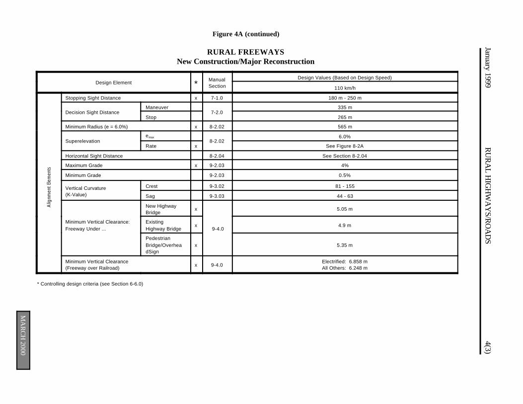
Figure 4A (continued)
RURAL FREEWAYSNew Construction/Major Reconstruction
January 1999R
UR
AL H
IGH
WA
YS/R
OA
DS
4(3)
Alig
nmen
t El
emen
ts
MA
RC
H 2000
Design Element *ManualSection
Design Values (Based on Design Speed)
110 km/h
Stopping Sight Distance x 7-1.0 180 m - 250 m
Decision Sight Distance Maneuver
7-2.0335 m
Stop 265 m
Minimum Radius (e = 6.0%) x 8-2.02 565 m
Superelevationemax
8-2.026.0%
Rate x See Figure 8-2A
Horizontal Sight Distance 8-2.04 See Section 8-2.04
Maximum Grade x 9-2.03 4%
Minimum Grade 9-2.03 0.5%
Vertical Curvature(K-Value)
Crest 9-3.02 81 - 155
Sag 9-3.03 44 - 63
Minimum Vertical Clearance:Freeway Under ...
New HighwayBridge
x
9-4.0
5.05 m
ExistingHighway Bridge
x 4.9 m
PedestrianBridge/OverheadSign
x 5.35 m
Minimum Vertical Clearance(Freeway over Railroad)
x 9-4.0Electrified: 6.858 mAll Others: 6.248 m
* Controlling design criteria (see Section 6-6.0)
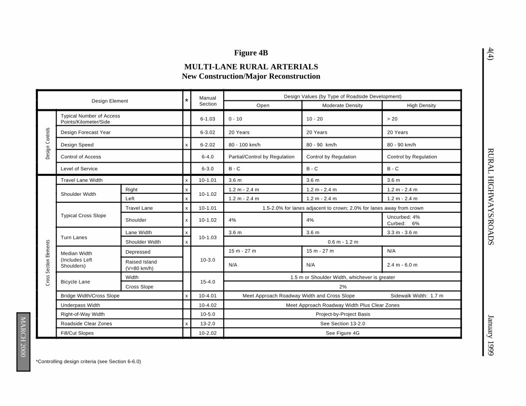
4(4)R
UR
AL H
IGH
WA
YS/R
OA
DS
January 1999
MA
RC
H 2000
Cro
ss S
ectio
n El
emen
ts
*Controlling design criteria (see Section 6-6.0)
Figure 4B
MULTI-LANE RURAL ARTERIALSNew Construction/Major Reconstruction
Design Element * ManualSection
Design Values (by Type of Roadside Development)
Open Moderate Density High Density
Des
ign
Con
trol
s
Typical Number of AccessPoints/Kilometer/Side
6-1.03 0 - 10 10 - 20 > 20
Design Forecast Year 6-3.02 20 Years 20 Years 20 Years
Design Speed x 6-2.02 80 - 100 km/h 80 - 90 km/h 80 - 90 km/h
Control of Access 6-4.0 Partial/Control by Regulation Control by Regulation Control by Regulation
Level of Service 6-3.0 B - C B - C B - C
Travel Lane Width x 10-1.01 3.6 m 3.6 m 3.6 m
Shoulder WidthRight x
10-1.021.2 m - 2.4 m 1.2 m - 2.4 m 1.2 m - 2.4 m
Left x 1.2 m - 2.4 m 1.2 m - 2.4 m 1.2 m - 2.4 m
Typical Cross Slope
Travel Lane x 10-1.01 1.5-2.0% for lanes adjacent to crown; 2.0% for lanes away from crown
Shoulder x 10-1.02 4% 4%Uncurbed: 4%Curbed: 6%
Turn LanesLane Width x
10-1.033.6 m 3.6 m 3.3 m - 3.6 m
Shoulder Width x 0.6 m - 1.2 m
Median Width(Includes LeftShoulders)
Depressed
10-3.0
15 m - 27 m 15 m - 27 m N/A
Raised Island(V=80 km/h)
N/A N/A 2.4 m - 6.0 m
Bicycle LaneWidth
15-4.01.5 m or Shoulder Width, whichever is greater
Cross Slope 2%
Bridge Width/Cross Slope x 10-4.01 Meet Approach Roadway Width and Cross Slope Sidewalk Width: 1.7 m
Underpass Width 10-4.02 Meet Approach Roadway Width Plus Clear Zones
Right-of-Way Width 10-5.0 Project-by-Project Basis
Roadside Clear Zones x 13-2.0 See Section 13-2.0
Fill/Cut Slopes 10-2.02 See Figure 4G
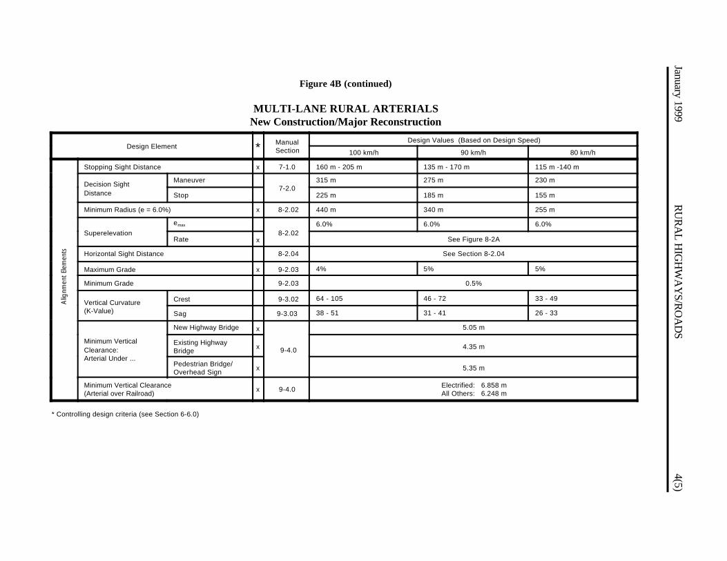
Figure 4B (continued)
MULTI-LANE RURAL ARTERIALSNew Construction/Major Reconstruction
January 1999R
UR
AL H
IGH
WA
YS/R
OA
DS
4(5) A
lignm
ent
Elem
ents
Design Element * ManualSection
Design Values (Based on Design Speed)
100 km/h 90 km/h 80 km/h
Stopping Sight Distance x 7-1.0 160 m - 205 m 135 m - 170 m 115 m -140 m
Decision SightDistance
Maneuver7-2.0
315 m 275 m 230 m
Stop 225 m 185 m 155 m
Minimum Radius (e = 6.0%) x 8-2.02 440 m 340 m 255 m
Superelevation
emax
8-2.026.0% 6.0% 6.0%
Rate x See Figure 8-2A
Horizontal Sight Distance 8-2.04 See Section 8-2.04
Maximum Grade x 9-2.03 4% 5% 5%
Minimum Grade 9-2.03 0.5%
Vertical Curvature(K-Value)
Crest 9-3.02 64 - 105 46 - 72 33 - 49
Sag 9-3.03 38 - 51 31 - 41 26 - 33
Minimum VerticalClearance:Arterial Under ...
New Highway Bridge x
9-4.0
5.05 m
Existing HighwayBridge
x 4.35 m
Pedestrian Bridge/Overhead Sign
x 5.35 m
Minimum Vertical Clearance(Arterial over Railroad)
x 9-4.0Electrified: 6.858 mAll Others: 6.248 m
* Controlling design criteria (see Section 6-6.0)
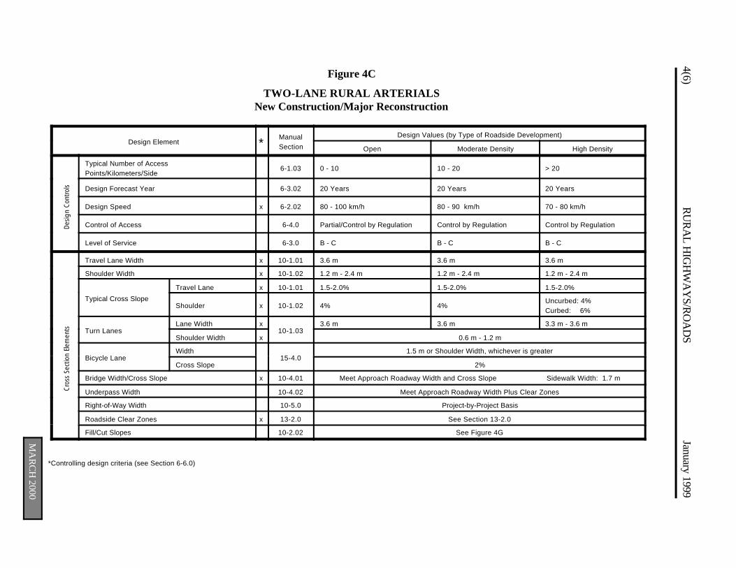
MA
RC
H 2000
4(6)R
UR
AL H
IGH
WA
YS/R
OA
DS
January 1999
*Controlling design criteria (see Section 6-6.0)
Figure 4C
TWO-LANE RURAL ARTERIALSNew Construction/Major Reconstruction
Design Element *ManualSection
Design Values (by Type of Roadside Development)
Open Moderate Density High Density
Des
ign
Con
trol
s
Typical Number of AccessPoints/Kilometers/Side
6-1.03 0 - 10 10 - 20 > 20
Design Forecast Year 6-3.02 20 Years 20 Years 20 Years
Design Speed x 6-2.02 80 - 100 km/h 80 - 90 km/h 70 - 80 km/h
Control of Access 6-4.0 Partial/Control by Regulation Control by Regulation Control by Regulation
Level of Service 6-3.0 B - C B - C B - C
Cro
ss S
ectio
n El
emen
ts
Travel Lane Width x 10-1.01 3.6 m 3.6 m 3.6 m
Shoulder Width x 10-1.02 1.2 m - 2.4 m 1.2 m - 2.4 m 1.2 m - 2.4 m
Typical Cross Slope
Travel Lane x 10-1.01 1.5-2.0% 1.5-2.0% 1.5-2.0%
Shoulder x 10-1.02 4% 4%Uncurbed: 4%Curbed: 6%
Turn LanesLane Width x
10-1.033.6 m 3.6 m 3.3 m - 3.6 m
Shoulder Width x 0.6 m - 1.2 m
Bicycle LaneWidth
15-4.01.5 m or Shoulder Width, whichever is greater
Cross Slope 2%
Bridge Width/Cross Slope x 10-4.01 Meet Approach Roadway Width and Cross Slope Sidewalk Width: 1.7 m
Underpass Width 10-4.02 Meet Approach Roadway Width Plus Clear Zones
Right-of-Way Width 10-5.0 Project-by-Project Basis
Roadside Clear Zones x 13-2.0 See Section 13-2.0
Fill/Cut Slopes 10-2.02 See Figure 4G
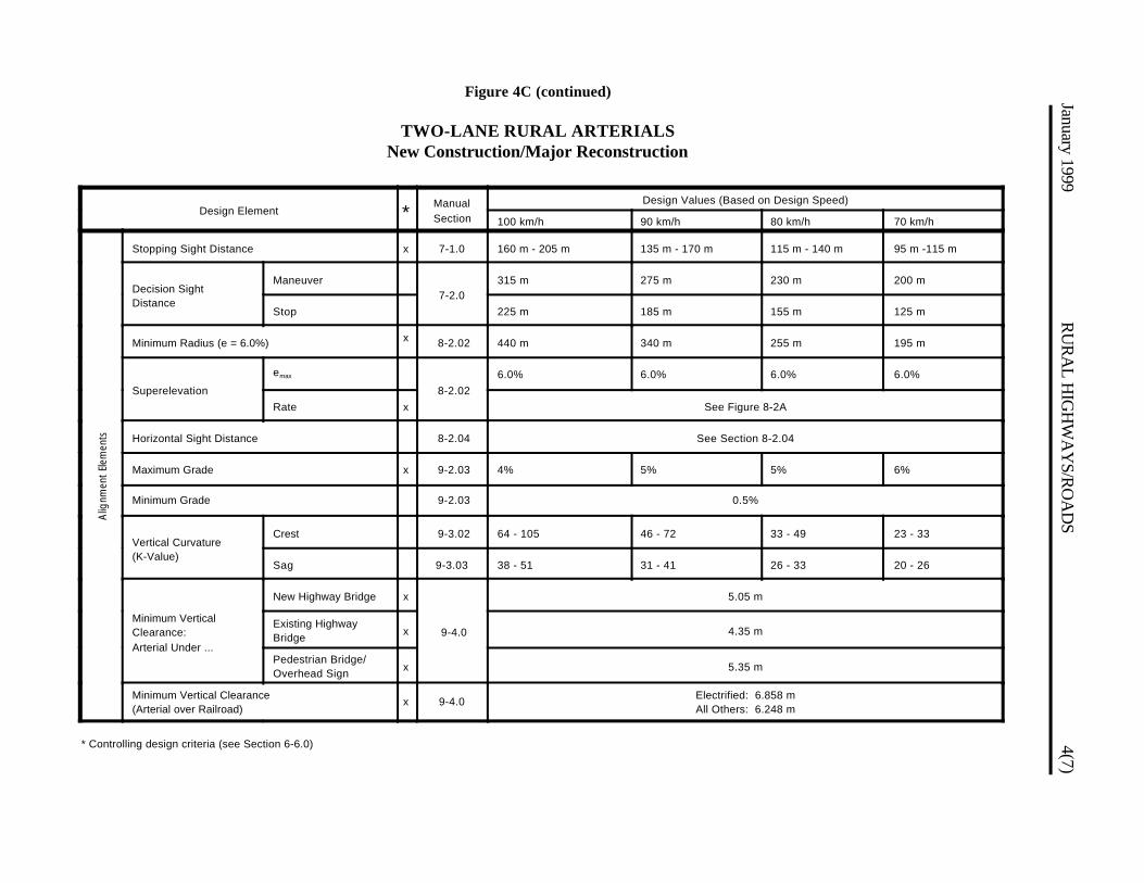
January 1999R
UR
AL H
IGH
WA
YS/R
OA
DS
4(7)Figure 4C (continued)
TWO-LANE RURAL ARTERIALSNew Construction/Major Reconstruction
Alig
nmen
t El
emen
ts
Design Element *ManualSection
Design Values (Based on Design Speed)
100 km/h 90 km/h 80 km/h 70 km/h
Stopping Sight Distance x 7-1.0 160 m - 205 m 135 m - 170 m 115 m - 140 m 95 m -115 m
Decision SightDistance
Maneuver7-2.0
315 m 275 m 230 m 200 m
Stop 225 m 185 m 155 m 125 m
Minimum Radius (e = 6.0%) x 8-2.02 440 m 340 m 255 m 195 m
Superelevation
emax
8-2.02
6.0% 6.0% 6.0% 6.0%
Rate x See Figure 8-2A
Horizontal Sight Distance 8-2.04 See Section 8-2.04
Maximum Grade x 9-2.03 4% 5% 5% 6%
Minimum Grade 9-2.03 0.5%
Vertical Curvature(K-Value)
Crest 9-3.02 64 - 105 46 - 72 33 - 49 23 - 33
Sag 9-3.03 38 - 51 31 - 41 26 - 33 20 - 26
Minimum VerticalClearance:Arterial Under ...
New Highway Bridge x
9-4.0
5.05 m
Existing HighwayBridge
x 4.35 m
Pedestrian Bridge/Overhead Sign
x 5.35 m
Minimum Vertical Clearance(Arterial over Railroad)
x 9-4.0Electrified: 6.858 mAll Others: 6.248 m
* Controlling design criteria (see Section 6-6.0)

MA
RC
H 2000
4(8)R
UR
AL H
IGH
WA
YS/R
OA
DS
January 1999 D
esig
n C
ontr
ols
Cro
ss S
ectio
n El
emen
ts
*Controlling design criteria (see Section 6-6.0)
Footnote:
(1) Bridge Width. See Section 3-2.04 for local bridge projects.
Figure 4D
RURAL COLLECTOR ROADSNew Construction/Major Reconstruction
Design Element * ManualSection
Design Values (by Type of Roadside Development)
Open Moderate Density High Density
Typical Number of AccessPoints/Kilometers/Side 6-1.03 0 - 10 10 - 20 > 20
Design Forecast Year 6-3.02 20 Years 20 Years 20 Years
Design Speed
AADT < 400
x 6-2.02
50 - 60 km/h N/A N/A
AADT: 400 - 2000 60 - 80 km/h 60 - 70 km/h N/A
AADT > 2000 80 km/h 70 - 80 km/h 60 - 70 km/h
Control of Access 6-4.0 Control by Regulation Control by Regulation Control by Regulation
Level of Service 6-3.0 C - D C - D C - D
Travel Lane Width
AADT < 400
x 10-1.01
3.0 m N/A N/A
AADT: 400 - 1500 3.3 m (V$60); 3.0 m (V#50) 3.3 m (V$60); 3.0 m (V#50) N/A
AADT: 1500 - 2000 3.3 m 3.3 m N/A
AADT > 2000 3.6 m 3.6 m 3.6 m
Shoulder WidthAADT # 1500
x 10-1.020.6 m - 2.4 m 0.6 m - 2.4 m N/A
AADT > 1500 1.2 m - 2.4 m 1.2 m - 2.4 m 1.2 m - 2.4 m
Typical Cross SlopeTravel Lane x 10-1.01 1.5-2.0% 1.5-2.0% 1.5-2.0%
Shoulder x 10-1.02 4% Uncurbed: 4%Curbed: 6%
Uncurbed: 4%Curbed: 6%
Turn LanesLane Width x
10-1.030.3 m Less Than Travel Lane Width — Same as Travel Lane
Shoulder Width x 0.6 m - 1.2 m
Bicycle LaneWidth
15-4.01.5 m or Shoulder Width, whichever is greater
Cross Slope 2%
Bridge Width/Cross Slope (1) x 10-4.01 Meet Approach Roadway Width and Cross Slope Sidewalk Width: 1.7 m
Underpass Width 10-4.02 Meet Approach Roadway Width Plus Clear Zones
Right-of-Way Width 10-5.0 Project-by-Project Basis
Roadside Clear Zones x 13-2.0 See Section 13-2.0
Fill/Cut Slopes 10-2.02 See Figure 4G

Figure 4D (continued)
RURAL COLLECTOR ROADSNew Construction/Major Reconstruction
Alig
nmen
t El
emen
ts
January 1999R
UR
AL H
IGH
WA
YS/R
OA
DS
4(9)
Design Element * ManualSection
Design Values (Based on Design Speed)
80 km/h 70 km/h 60 km/h 50 km/h
Stopping Sight Distance x 7-1.0 115 m - 140 m 95 m - 115 m 75 m - 85 m 60 m - 65 m
Decision SightDistance
Maneuver7-2.0
230 m 200 m 175 m 145 m
Stop 155 m 125 m 95 m 75 m
Minimum Radius (e = 6.0%) x 8-2.02 255 m 195 m 135 m 90 m
Superelevation
emax
8-2.026.0% 6.0% 6.0% 6.0%
Rate x See Figure 8-2A
Horizontal Sight Distance 8-2.04 See Section 8-2.04
Maximum Grade x 9-2.03 7% 8% 8% 9%
Minimum Grade 9-2.03 0.5%
Vertical Curvature(K-Value)
Crest 9-3.02 33 - 49 23 - 33 14 - 18 9 - 11
Sag 9-3.03 26 - 33 20 - 26 15 - 18 11 - 13
Minimum VerticalClearance:Collector Under ...
New HighwayBridge
x 9-4.0
4.5 m
Existing HighwayBridge x 4.35 m
Minimum Vertical Clearance(Collector over Railroad) x 9-4.0 Electrified: 6.858 m
All Others: 6.248 m
* Controlling design criteria (see Section 6-6.0)
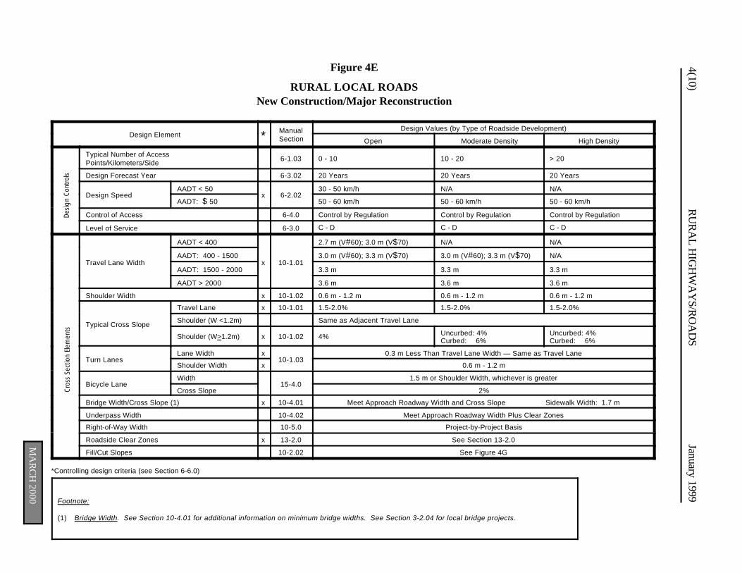
MA
RC
H 2000
4(10)R
UR
AL H
IGH
WA
YS/R
OA
DS
January 1999 D
esig
n C
ontr
ols
Cro
ss S
ectio
n El
emen
ts
*Controlling design criteria (see Section 6-6.0)
Footnote:
(1) Bridge Width. See Section 10-4.01 for additional information on minimum bridge widths. See Section 3-2.04 for local bridge projects.
Figure 4E
RURAL LOCAL ROADSNew Construction/Major Reconstruction
Design Element * ManualSection
Design Values (by Type of Roadside Development)
Open Moderate Density High Density
Typical Number of AccessPoints/Kilometers/Side
6-1.03 0 - 10 10 - 20 > 20
Design Forecast Year 6-3.02 20 Years 20 Years 20 Years
Design SpeedAADT < 50
x 6-2.0230 - 50 km/h N/A N/A
AADT: $ 50 50 - 60 km/h 50 - 60 km/h 50 - 60 km/h
Control of Access 6-4.0 Control by Regulation Control by Regulation Control by Regulation
Level of Service 6-3.0 C - D C - D C - D
Travel Lane Width
AADT < 400
x 10-1.01
2.7 m (V#60); 3.0 m (V$70) N/A N/A
AADT: 400 - 1500 3.0 m (V#60); 3.3 m (V$70) 3.0 m (V#60); 3.3 m (V$70) N/A
AADT: 1500 - 2000 3.3 m 3.3 m 3.3 m
AADT > 2000 3.6 m 3.6 m 3.6 m
Shoulder Width x 10-1.02 0.6 m - 1.2 m 0.6 m - 1.2 m 0.6 m - 1.2 m
Typical Cross Slope
Travel Lane x 10-1.01 1.5-2.0% 1.5-2.0% 1.5-2.0%
Shoulder (W <1.2m) Same as Adjacent Travel Lane
Shoulder (W>1.2m) x 10-1.02 4% Uncurbed: 4%Curbed: 6%
Uncurbed: 4%Curbed: 6%
Turn LanesLane Width x
10-1.030.3 m Less Than Travel Lane Width — Same as Travel Lane
Shoulder Width x 0.6 m - 1.2 m
Bicycle Lane Width
15-4.01.5 m or Shoulder Width, whichever is greater
Cross Slope 2%
Bridge Width/Cross Slope (1) x 10-4.01 Meet Approach Roadway Width and Cross Slope Sidewalk Width: 1.7 m
Underpass Width 10-4.02 Meet Approach Roadway Width Plus Clear Zones
Right-of-Way Width 10-5.0 Project-by-Project Basis
Roadside Clear Zones x 13-2.0 See Section 13-2.0
Fill/Cut Slopes 10-2.02 See Figure 4G
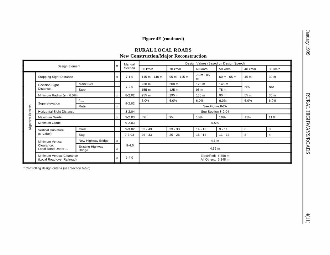
Figure 4E (continued)
RURAL LOCAL ROADSNew Construction/Major Reconstruction
January 1999R
UR
AL H
IGH
WA
YS/R
OA
DS
4(11) A
lignm
ent
Elem
ents
Design Element * ManualSection
Design Values (Based on Design Speed)
80 km/h 70 km/h 60 km/h 50 km/h 40 km/h 30 km/h
Stopping Sight Distance x 7-1.0 115 m - 140 m 95 m - 115 m75 m - 85m
60 m - 65 m 45 m 30 m
Decision SightDistance
Maneuver7-2.0
230 m 200 m 175 m 145 mN/A N/A
Stop 155 m 125 m 95 m 75 m
Minimum Radius (e = 6.0%) x 8-2.02 255 m 195 m 135 m 90 m 55 m 30 m
Superelevationemax
8-2.026.0% 6.0% 6.0% 6.0% 6.0% 6.0%
Rate x See Figure 8-2A
Horizontal Sight Distance 8-2.04 See Section 8-2.04
Maximum Grade x 9-2.03 8% 9% 10% 10% 11% 11%
Minimum Grade 9-2.03 0.5%
Vertical Curvature(K-Value)
Crest 9-3.02 33 - 49 23 - 33 14 - 18 9 - 11 6 3
Sag 9-3.03 26 - 33 20 - 26 15 - 18 11 - 13 8 4
Minimum VerticalClearance:Local Road Under ...
New Highway Bridge x
9-4.0
4.5 m
Existing HighwayBridge x 4.35 m
Minimum Vertical Clearance(Local Road over Railroad)
x 9-4.0Electrified: 6.858 mAll Others: 6.248 m
* Controlling design criteria (see Section 6-6.0)
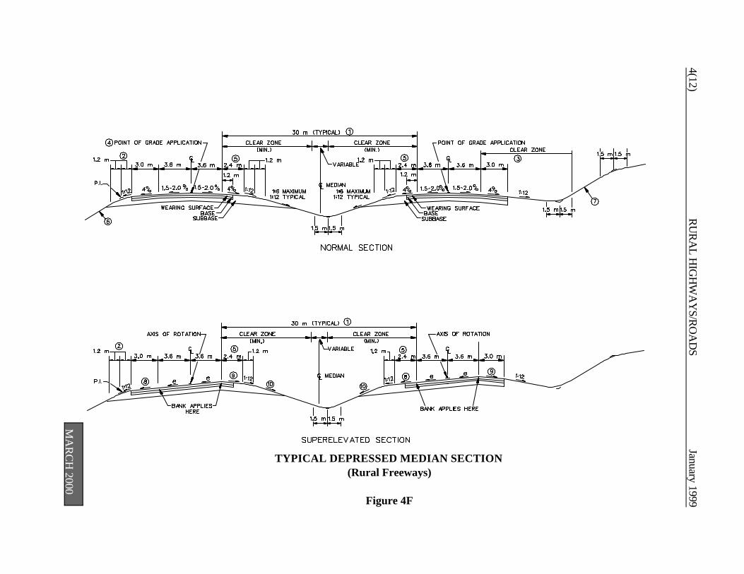
4(12)R
UR
AL H
IGH
WA
YS/R
OA
DS
January 1999
TYPICAL DEPRESSED MEDIAN SECTION(Rural Freeways)
Figure 4F
MA
RC
H 2000
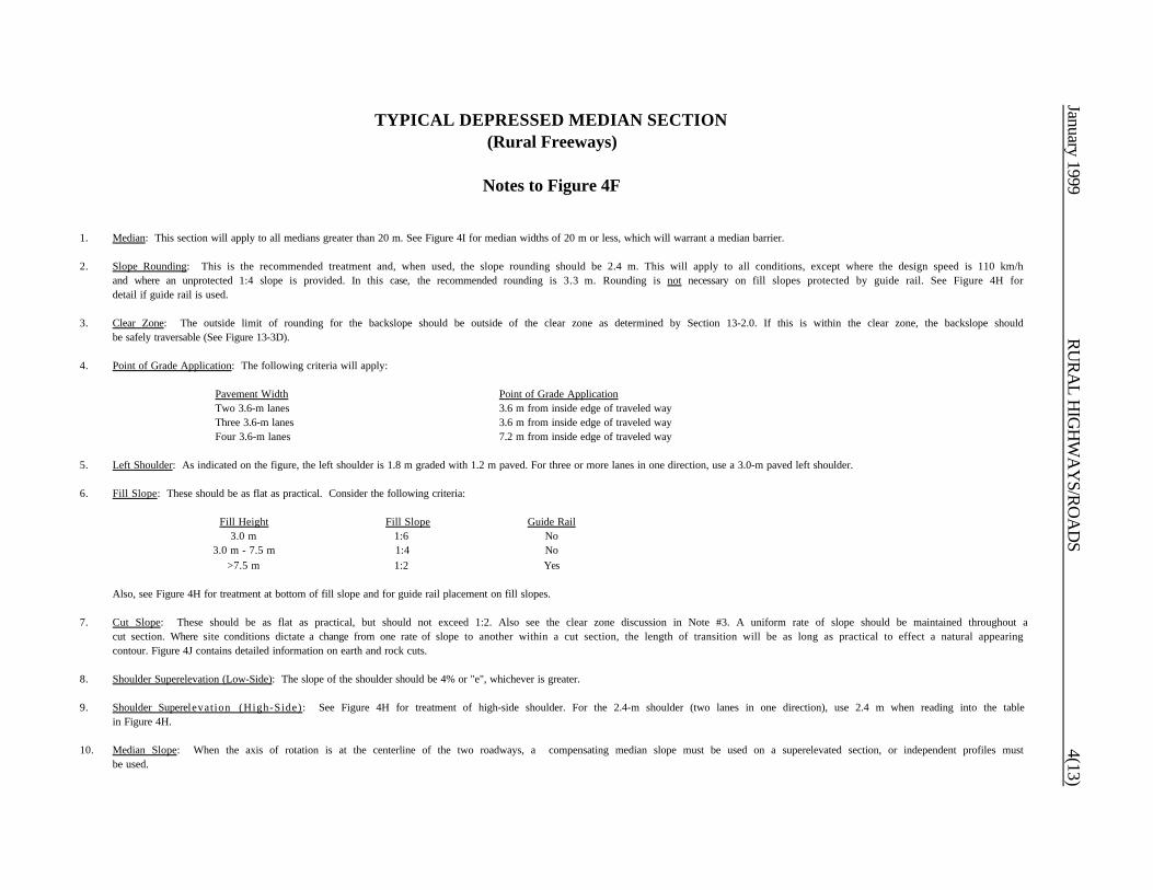
January 1999R
UR
AL H
IGH
WA
YS/R
OA
DS
4(13)
TYPICAL DEPRESSED MEDIAN SECTION(Rural Freeways)
Notes to Figure 4F
1. Median: This section will apply to all medians greater than 20 m. See Figure 4I for median widths of 20 m or less, which will warrant a median barrier.
2. Slope Rounding: This is the recommended treatment and, when used, the slope rounding should be 2.4 m. This will apply to all conditions, except where the design speed is 110 km/hand where an unprotected 1:4 slope is provided. In this case, the recommended rounding is 3.3 m. Rounding is not necessary on fill slopes protected by guide rail. See Figure 4H fordetail if guide rail is used.
3. Clear Zone: The outside limit of rounding for the backslope should be outside of the clear zone as determined by Section 13-2.0. If this is within the clear zone, the backslope shouldbe safely traversable (See Figure 13-3D).
4. Point of Grade Application: The following criteria will apply:
Pavement Width Point of Grade ApplicationTwo 3.6-m lanes 3.6 m from inside edge of traveled wayThree 3.6-m lanes 3.6 m from inside edge of traveled wayFour 3.6-m lanes 7.2 m from inside edge of traveled way
5. Left Shoulder: As indicated on the figure, the left shoulder is 1.8 m graded with 1.2 m paved. For three or more lanes in one direction, use a 3.0-m paved left shoulder.
6. Fill Slope: These should be as flat as practical. Consider the following criteria:
Fill Height Fill Slope Guide Rail3.0 m 1:6 No
3.0 m - 7.5 m 1:4 No>7.5 m 1:2 Yes
Also, see Figure 4H for treatment at bottom of fill slope and for guide rail placement on fill slopes.
7. Cut Slope: These should be as flat as practical, but should not exceed 1:2. Also see the clear zone discussion in Note #3. A uniform rate of slope should be maintained throughout acut section. Where site conditions dictate a change from one rate of slope to another within a cut section, the length of transition will be as long as practical to effect a natural appearingcontour. Figure 4J contains detailed information on earth and rock cuts.
8. Shoulder Superelevation (Low-Side): The slope of the shoulder should be 4% or "e", whichever is greater.
9. Shoulder Superelevation (High-Side): See Figure 4H for treatment of high-side shoulder. For the 2.4-m shoulder (two lanes in one direction), use 2.4 m when reading into the tablein Figure 4H.
10. Median Slope: When the axis of rotation is at the centerline of the two roadways, a compensating median slope must be used on a superelevated section, or independent profiles mustbe used.
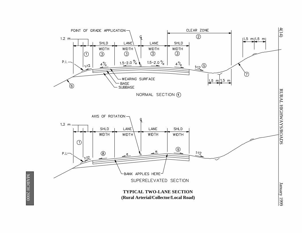
4(14)R
UR
AL H
IGH
WA
YS/R
OA
DS
January 1999
TYPICAL TWO-LANE SECTION(Rural Arterial/Collector/Local Road)
MA
RC
H 2000
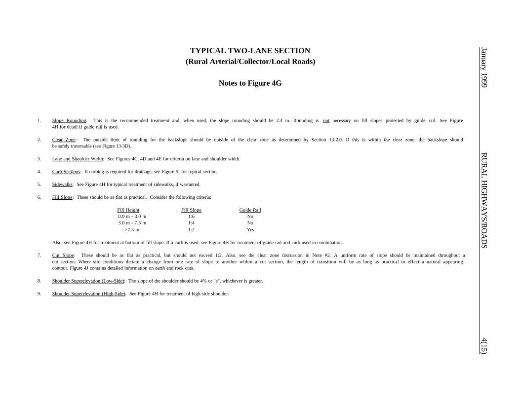
January 1999R
UR
AL H
IGH
WA
YS/R
OA
DS
4(15)
TYPICAL TWO-LANE SECTION(Rural Arterial/Collector/Local Roads)
Notes to Figure 4G
1. Slope Rounding: This is the recommended treatment and, when used, the slope rounding should be 2.4 m. Rounding is not necessary on fill slopes protected by guide rail. See Figure4H for detail if guide rail is used.
2. Clear Zone: The outside limit of rounding for the backslope should be outside of the clear zone as determined by Section 13-2.0. If this is within the clear zone, the backslope shouldbe safely traversable (see Figure 13-3D).
3. Lane and Shoulder Width: See Figures 4C, 4D and 4E for criteria on lane and shoulder width.
4. Curb Sections: If curbing is required for drainage, see Figure 5I for typical section.
5. Sidewalks: See Figure 4H for typical treatment of sidewalks, if warranted.
6. Fill Slope: These should be as flat as practical. Consider the following criteria:
Fill Height Fill Slope Guide Rail0.0 m - 3.0 m 1:6 No3.0 m - 7.5 m 1:4 No
>7.5 m 1:2 Yes
Also, see Figure 4H for treatment at bottom of fill slope. If a curb is used, see Figure 4H for treatment of guide rail and curb used in combination.
7. Cut Slope: These should be as flat as practical, but should not exceed 1:2. Also, see the clear zone discussion in Note #2. A uniform rate of slope should be maintained throughout acut section. Where site conditions dictate a change from one rate of slope to another within a cut section, the length of transition will be as long as practical to effect a natural appearingcontour. Figure 4J contains detailed information on earth and rock cuts.
8. Shoulder Superelevation (Low-Side): The slope of the shoulder should be 4% or "e", whichever is greater.
9. Shoulder Superelevation (High-Side): See Figure 4H for treatment of high-side shoulder.
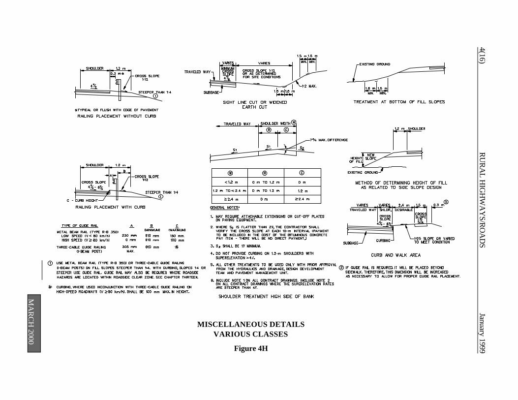
4(16)R
UR
AL H
IGH
WA
YS/R
OA
DS
January 1999
MISCELLANEOUS DETAILSVARIOUS CLASSES
Figure 4H
MA
RC
H 2000
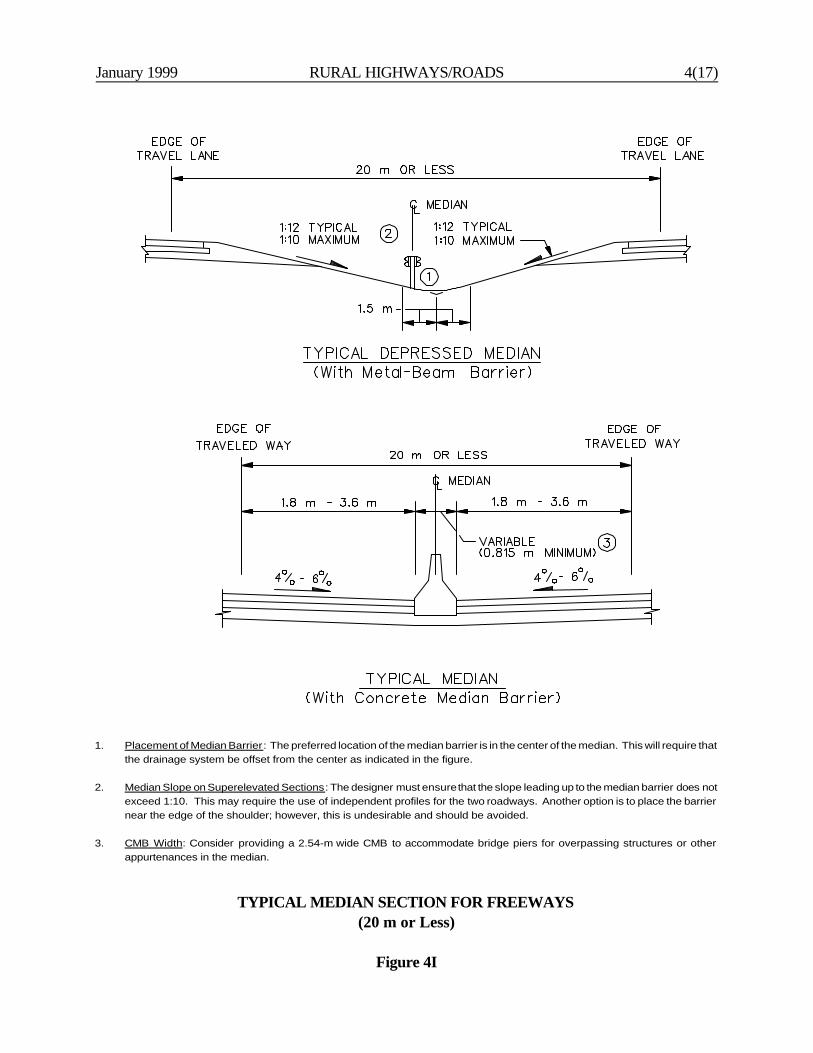
January 1999 RURAL HIGHWAYS/ROADS 4(17)
1. Placement of Median Barrier: The preferred location of the median barrier is in the center of the median. This will require thatthe drainage system be offset from the center as indicated in the figure.
2. Median Slope on Superelevated Sections: The designer must ensure that the slope leading up to the median barrier does notexceed 1:10. This may require the use of independent profiles for the two roadways. Another option is to place the barriernear the edge of the shoulder; however, this is undesirable and should be avoided.
3. CMB Width: Consider providing a 2.54-m wide CMB to accommodate bridge piers for overpassing structures or otherappurtenances in the median.
TYPICAL MEDIAN SECTION FOR FREEWAYS(20 m or Less)
Figure 4I

4(18)R
UR
AL H
IGH
WA
YS/R
OA
DS
January 1999
Î To be increased as rock competencedecreases or as height of rock cutincreases.
Ï Rock slopes should be determined bygeological investigations and analysis.
Ð Slopes flatter than the 1:2 maximumare preferred and should be usedwhere site conditions allow. Generallya uniform rate of slope should be heldthroughout a section. Where siteconditions dictate a change from onerate of slope to another within a cutsection, the length of transition shouldbe as long as possible to effect anatural appearing contour.
Ñ The 6-m rock shelf may be reduced toa minimum of 1.5 m when: (a) duringconstruction, the rock elevation isfound to be lower than anticipatedduring design, (b) it is desirable toreduce surplus excavation, and (c) it isdesirable to minimize right-of-wayneeds.
DETAILS OF CUT SECTIONSFigure 4J
January 1999 URBAN HIGHWAYS AND STREETS 5-i
Chapter Five
URBAN HIGHWAYS AND STREETS(New Construction/Major Reconstruction)
Table of Contents
Page
Figure 5A Urban Freeways . . . . . . . . . . . . . . . . . . . . . . . . . . . . . . . . . . . . . . . . . . . . . . 5(2)
Figure 5B Multi-Lane Principal Urban Arterials . . . . . . . . . . . . . . . . . . . . . . . . . . . . . . . . 5(4)
Figure 5C Two-Lane Principal Urban Arterials . . . . . . . . . . . . . . . . . . . . . . . . . . . . . . . . 5(6)
Figure 5D Minor Urban Arterial . . . . . . . . . . . . . . . . . . . . . . . . . . . . . . . . . . . . . . . . . 5(8)
Figure 5E Urban Collector Streets . . . . . . . . . . . . . . . . . . . . . . . . . . . . . . . . . . . . . . . . . 5(10)
Figure 5F Local Urban Street . . . . . . . . . . . . . . . . . . . . . . . . . . . . . . . . . . . . . . . . . . . . . 5(12)
Figure 5G Typical Depressed Median Section . . . . . . . . . . . . . . . . . . . . . . . . . . . . . . . . . 5(14)(Urban Freeways)
Figure 5H Typical Raised Median Section . . . . . . . . . . . . . . . . . . . . . . . . . . . . . . . . . . . . 5(16)(Urban Arterials)
Figure 5I Typical Two-Lane Section . . . . . . . . . . . . . . . . . . . . . . . . . . . . . . . . . . . . . . . 5(18)(Urban Arterial/Collector/Local Streets)
Figure 5J Miscellaneous Details, Various Classes . . . . . . . . . . . . . . . . . . . . . . . . . . . . . . 5(20)
Figure 5K Typical Median Section for Freeways . . . . . . . . . . . . . . . . . . . . . . . . . . . . . . . 5(21)(20 m or Less)
Figure 5L Details of Cut Sections . . . . . . . . . . . . . . . . . . . . . . . . . . . . . . . . . . . . . . . . . . 5(22)
Figure 5M Typical Section for Urban Freeways . . . . . . . . . . . . . . . . . . . . . . . . . . . . . . . . 5(23)(High-Volume/Incident Management Freeways)

5-ii URBAN HIGHWAYS AND STREETS January 1999

January 1999 URBAN HIGHWAYS AND STREETS 5(1)
Chapter Five
URBAN HIGHWAYS AND STREETS(New Construction/Major Reconstruction)
This chapter presents the Department's criteria for the design of urban highways and streets. They applyto new construction and major reconstruction projects. The designer should consider the following in theuse of the tables:
1. Functional/Design Classification. The selection of design values for new construction and majorreconstruction depends on the functional and, for non-freeways, the design classification of thehighway facility. This is discussed in Section 6-1.0.
2. Capacity Analyses. Section 6-3.0 discusses highway capacity. Several highway design elements(e.g., the number of travel lanes) will be determined in part by the capacity analysis. As discussedin Section 6-3.0, the capacity analysis will be based on:
a. the design hourly volume (DHV), usually 20 years from the construction completion date;
b. the level of service, as determined from the tables in this chapter; and
c. the capacity analysis, using the techniques in the HCM.
3. Cross Section Elements. The designer should realize that some of the cross section elementsincluded in a table (e.g., median width) are not automatically warranted in the project design. Thevalues in the tables will only apply after the decision has been made to include the element in thehighway cross section.
4. Manual Section References. These tables are intended to provide a concise listing of design valuesfor easy use. However, the designer should review the Manual section references for greaterinsight into the design elements.

MA
RC
H 2000
5(2)U
RB
AN
HIG
HW
AY
S AN
D STR
EETSJanuary 1999
Des
ign
Con
trol
s C
ross
Sec
tion
Elem
ents
*Controlling design criteria (see Section 6-6.0)
Footnote:
(1) Shoulder Width. Where the truck volumes exceed 250 DDHV, both the right and left shoulders should be 3.6 m. Where warranted for high-volume/incidentmanagement sites, use a 4.8-m left shoulder.
Figure 5A
URBAN FREEWAYSNew Construction/Major Reconstruction
Design Element *ManualSection
Design Values (By Type of Area)
Suburban/Intermediate Built-up
Design Forecast Year 6-3.02 20 Years 20 Years
Design Speed x 6-2.02 100 - 110 km/h 80-90 km/h
Control of Access 6-4.0 Full Control Full Control
Level of Service 6-3.0 B - C B - C
Lane Width x 10-1.01 3.6 m 3.6 m
Shoulder Width (1)
Right x 3.0 m 3.0 m
Left — 4 Lanes x 10-1.02 2.4 m (1.2 m Paved +1.2 m Graded) 2.4 m (1.2 m Paved +1.2 m Graded)
Left — 6+ Lanes x 3.0 m 3.0 m
Typical Cross SlopeTravel Lane x 10-1.01 1.5-2.0% for lanes adjacent to crown; 2.0% for lanes away from crown
Shoulder x 10-1.02 4%; with CMB, 4% - 6% for left shoulder 4%; with CMB, 4% - 6% for left shoulder
Median Width (includes left shoulders) 10-3.0 See Figure 5K - 27 m See Figure 5K - 27 m
Bridge Width/Cross Slope x 10-4.01 Meet Approach Roadway Width and Cross Slope
Underpass Width 10-4.02 Meet Approach Roadway Width Plus Clear Zones
Right-of-Way Width 10-5.0 Max: 30 m Beyond Edge of Traveled Way
Roadside Clear Zones x 13-2.0 See Section 13-2.0
Fill/Cut Slopes 10-2.02 See Figure 5G
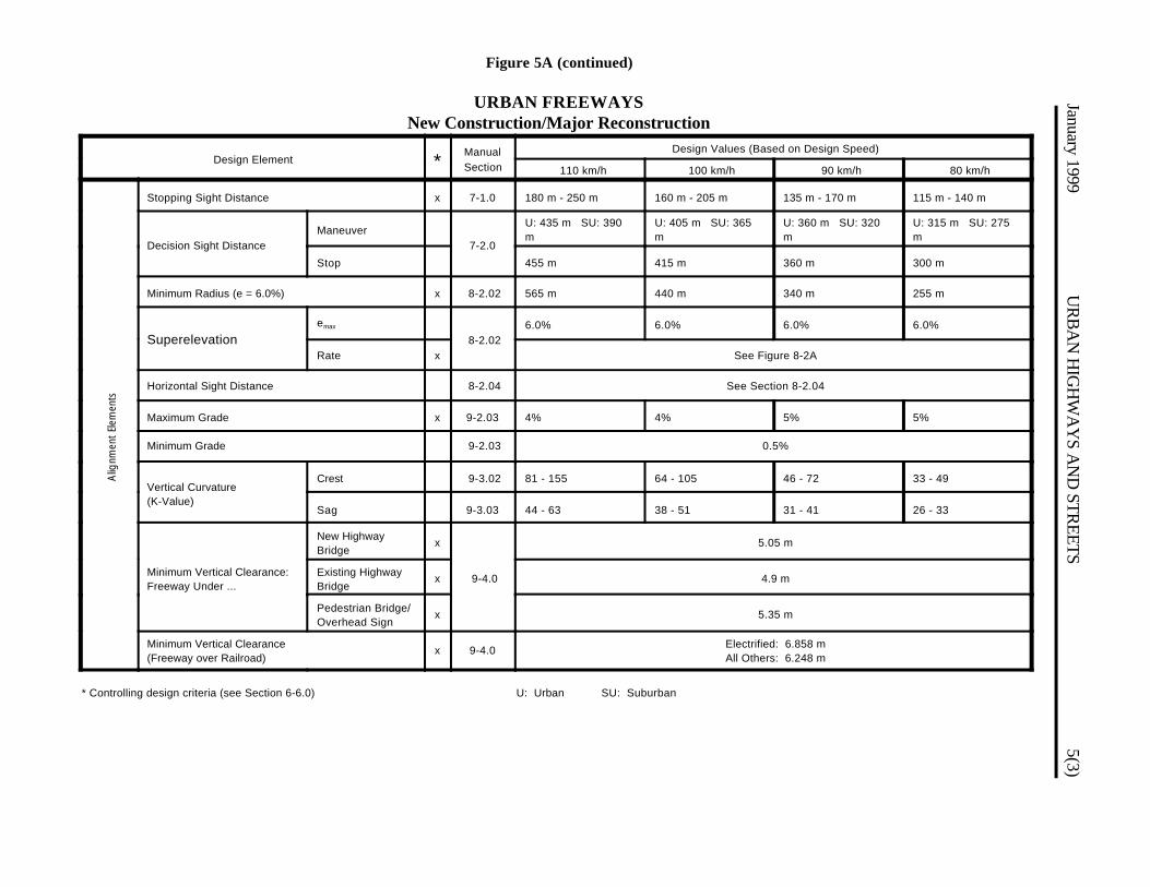
Figure 5A (continued)
URBAN FREEWAYSNew Construction/Major Reconstruction
January 1999U
RB
AN
HIG
HW
AY
S AN
D STR
EETS5(3)
Alig
nmen
t El
emen
ts
Design Element *ManualSection
Design Values (Based on Design Speed)
110 km/h 100 km/h 90 km/h 80 km/h
Stopping Sight Distance x 7-1.0 180 m - 250 m 160 m - 205 m 135 m - 170 m 115 m - 140 m
Decision Sight Distance Maneuver
7-2.0
U: 435 m SU: 390m
U: 405 m SU: 365m
U: 360 m SU: 320m
U: 315 m SU: 275m
Stop 455 m 415 m 360 m 300 m
Minimum Radius (e = 6.0%) x 8-2.02 565 m 440 m 340 m 255 m
Superelevationemax
8-2.026.0% 6.0% 6.0% 6.0%
Rate x See Figure 8-2A
Horizontal Sight Distance 8-2.04 See Section 8-2.04
Maximum Grade x 9-2.03 4% 4% 5% 5%
Minimum Grade 9-2.03 0.5%
Vertical Curvature(K-Value)
Crest 9-3.02 81 - 155 64 - 105 46 - 72 33 - 49
Sag 9-3.03 44 - 63 38 - 51 31 - 41 26 - 33
Minimum Vertical Clearance:Freeway Under ...
New HighwayBridge
x
9-4.0
5.05 m
Existing HighwayBridge
x 4.9 m
Pedestrian Bridge/Overhead Sign
x 5.35 m
Minimum Vertical Clearance(Freeway over Railroad)
x 9-4.0Electrified: 6.858 mAll Others: 6.248 m
* Controlling design criteria (see Section 6-6.0) U: Urban SU: Suburban
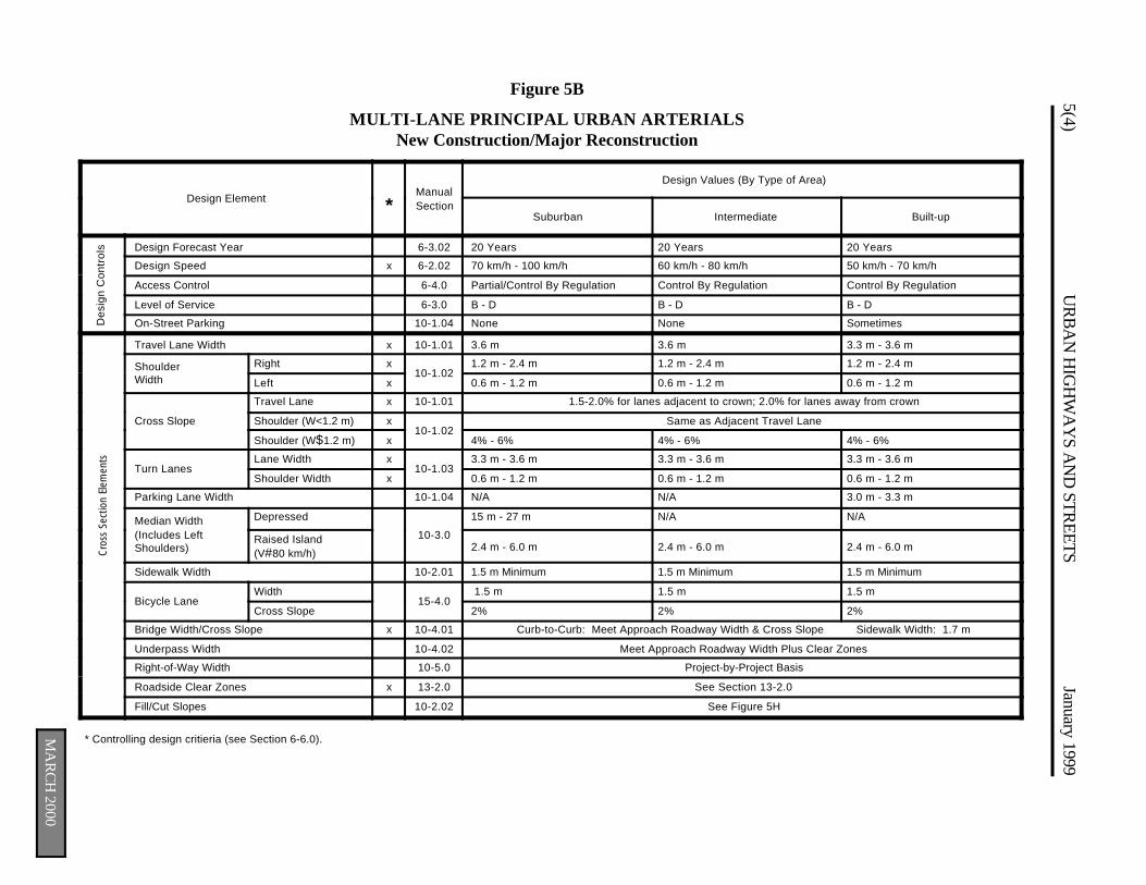
5(4)U
RB
AN
HIG
HW
AY
S AN
D STR
EETSJanuary 1999
MA
RC
H 2000
Des
ign
Con
trol
sFigure 5B
MULTI-LANE PRINCIPAL URBAN ARTERIALSNew Construction/Major Reconstruction
Design Element *ManualSection
Design Values (By Type of Area)
Suburban Intermediate Built-up
Design Forecast Year 6-3.02 20 Years 20 Years 20 Years
Design Speed x 6-2.02 70 km/h - 100 km/h 60 km/h - 80 km/h 50 km/h - 70 km/h
Access Control 6-4.0 Partial/Control By Regulation Control By Regulation Control By Regulation
Level of Service 6-3.0 B - D B - D B - D
On-Street Parking 10-1.04 None None Sometimes
Travel Lane Width x 10-1.01 3.6 m 3.6 m 3.3 m - 3.6 m
Shoulder Width
Right x10-1.02
1.2 m - 2.4 m 1.2 m - 2.4 m 1.2 m - 2.4 m
Left x 0.6 m - 1.2 m 0.6 m - 1.2 m 0.6 m - 1.2 m
Cross Slope
Travel Lane x 10-1.01 1.5-2.0% for lanes adjacent to crown; 2.0% for lanes away from crown
Shoulder (W<1.2 m) x10-1.02
Same as Adjacent Travel Lane
Shoulder (W$1.2 m) x 4% - 6% 4% - 6% 4% - 6%
Turn LanesLane Width x
10-1.033.3 m - 3.6 m 3.3 m - 3.6 m 3.3 m - 3.6 m
Shoulder Width x 0.6 m - 1.2 m 0.6 m - 1.2 m 0.6 m - 1.2 m
Parking Lane Width 10-1.04 N/A N/A 3.0 m - 3.3 m
Median Width (Includes Left Shoulders)
Depressed
10-3.0
15 m - 27 m N/A N/A
Raised Island(V#80 km/h)
2.4 m - 6.0 m 2.4 m - 6.0 m 2.4 m - 6.0 m
Sidewalk Width 10-2.01 1.5 m Minimum 1.5 m Minimum 1.5 m Minimum
Bicycle Lane Width
15-4.0 1.5 m 1.5 m 1.5 m
Cross Slope 2% 2% 2%
Bridge Width/Cross Slope x 10-4.01 Curb-to-Curb: Meet Approach Roadway Width & Cross Slope Sidewalk Width: 1.7 m
Underpass Width 10-4.02 Meet Approach Roadway Width Plus Clear Zones
Right-of-Way Width 10-5.0 Project-by-Project Basis
Roadside Clear Zones x 13-2.0 See Section 13-2.0
Fill/Cut Slopes 10-2.02 See Figure 5H
Cro
ss S
ectio
n El
emen
ts
* Controlling design critieria (see Section 6-6.0).
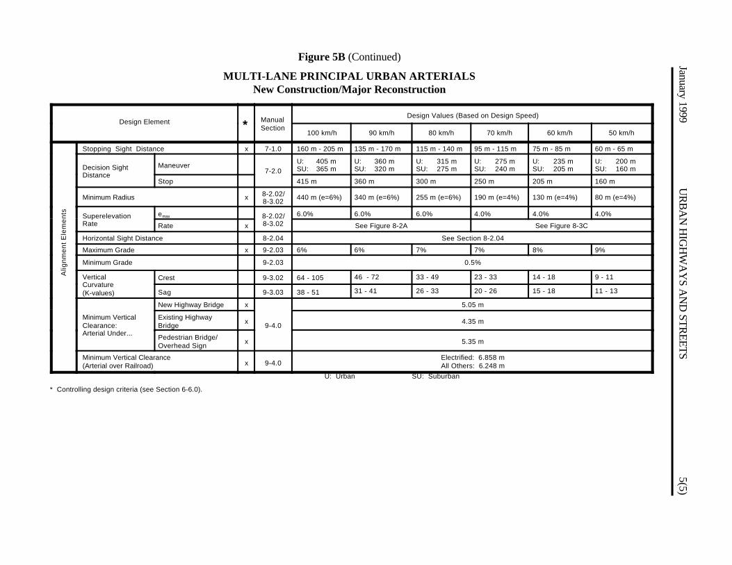
January 1999U
RB
AN
HIG
HW
AY
S AN
D STR
EETS5(5)
Figure 5B (Continued)
MULTI-LANE PRINCIPAL URBAN ARTERIALSNew Construction/Major Reconstruction
Design Element * ManualSection
Design Values (Based on Design Speed)
100 km/h 90 km/h 80 km/h 70 km/h 60 km/h 50 km/h
Stopping Sight Distance x 7-1.0 160 m - 205 m 135 m - 170 m 115 m - 140 m 95 m - 115 m 75 m - 85 m 60 m - 65 m
Decision Sight Distance
Maneuver7-2.0
U: 405 mSU: 365 m
U: 360 mSU: 320 m
U: 315 mSU: 275 m
U: 275 mSU: 240 m
U: 235 mSU: 205 m
U: 200 mSU: 160 m
Stop 415 m 360 m 300 m 250 m 205 m 160 m
Minimum Radius x 8-2.02/8-3.02
440 m (e=6%) 340 m (e=6%) 255 m (e=6%) 190 m (e=4%) 130 m (e=4%) 80 m (e=4%)
Superelevation Rate
emax 8-2.02/8-3.02
6.0% 6.0% 6.0% 4.0% 4.0% 4.0%
Rate x See Figure 8-2A See Figure 8-3C
Horizontal Sight Distance 8-2.04 See Section 8-2.04
Maximum Grade x 9-2.03 6% 6% 7% 7% 8% 9%
Minimum Grade 9-2.03 0.5%
Vertical Curvature (K-values)
Crest 9-3.02 64 - 105 46 - 72 33 - 49 23 - 33 14 - 18 9 - 11
A
lignm
ent
Ele
men
ts
Sag 9-3.03 38 - 51 31 - 41 26 - 33 20 - 26 15 - 18 11 - 13
Minimum Vertical Clearance: Arterial Under...
New Highway Bridge x
9-4.0
5.05 m
Existing HighwayBridge
x 4.35 m
Pedestrian Bridge/Overhead Sign
x 5.35 m
Minimum Vertical Clearance (Arterial over Railroad) x 9-4.0
Electrified: 6.858 mAll Others: 6.248 m
* Controlling design criteria (see Section 6-6.0).
U: Urban SU: Suburban
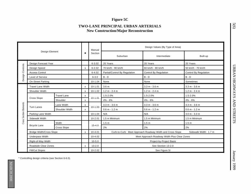
5(6)U
RB
AN
HIG
HW
AY
S AN
D STR
EETSJanuary 1999
MA
RC
H 2000
Des
ign
Con
trol
sC
ross
Sec
tion
Elem
ents
Figure 5C
TWO-LANE PRINCIPAL URBAN ARTERIALSNew Construction/Major Reconstruction
Design Element*
ManualSection
Design Values (By Type of Area)
Suburban Intermediate Built-up
Design Forecast Year 6-3.02 20 Years 20 Years 20 Years
Design Speed x 6-2.02 70 km/h - 90 km/h 60 km/h - 80 km/h 50 km/h - 70 km/h
Access Control 6-4.02 Partial/Control By Regulation Control By Regulation Control By Regulation
Level of Service 6-3.0 B - D B - D B - D
On-Street Parking 10-1.04 None None Sometimes
Travel Lane Width x 10-1.01 3.6 m 3.3 m - 3.6 m 3.3 m - 3.6 m
Shoulder Width x 10-1.02 1.2 m - 2.4 m 1.2 m - 2.4 m 1.2 m - 2.4 m
Cross SlopeTravel Lane x
10-1.011.5-2.0% 1.5-2.0% 1.5-2.0%
Shoulder x 4% - 6% 4% - 6% 4% - 6%
Turn LanesLane Width x
10-1.033.3 m - 3.6 m 3.3 m - 3.6 m 3.3 m - 3.6 m
Shoulder Width x 0.6 m - 1.2 m 0.6 m - 1.2 m 0.6 m - 1.2 m
Parking Lane Width 10-1.04 N/A N/A 3.0 m - 3.3 m
Sidewalk Width 10-2.01 1.5 m Minimum 1.5 m Minimum 1.5 m Minimum
Bicycle LaneWidth
15-4.01.5 m 1.5 m 1.5 m
Cross Slope 2% 2% 2%
Bridge Width/Cross Slope x 10-4.01 Curb-to-Curb: Meet Approach Roadway Width and Cross Slope Sidewalk Width: 1.7 m
Underpass Width 10-4.02 Meet Approach Roadway Width Plus Clear Zones
Right-of-Way Width 10-5.0 Project-by-Project Basis
Roadside Clear Zones x 13-2.0 See Section 13-2.0
Fill/Cut Slopes 10-2.02 See Figure 5I
* Controlling design critieria (see Section 6-6.0).

January 1999U
RB
AN
HIG
HW
AY
S AN
D STR
EETS5(7)
Figure 5C (Continued)
TWO-LANE PRINCIPAL URBAN ARTERIALSNew Construction/Major Reconstruction
Design Element * ManualSection
Design Values (Based on Design Speed)
90 km/h 80 km/h 70 km/h 60 km/h 50 km/h
Stopping Sight Distance x 7-1.0 135 m - 170 m 115 m - 140 m 95 m - 115 m 75 m - 85 m 60 m - 65 m
Decision Sight Distance
Maneuver7-2.0
U: 360 mSU: 320 m
U: 315 mSU: 275 m
U: 275 mSU: 240 m
U: 235 mSU: 205 m
U: 200 mSU: 160 m
Stop 360 m 300 m 250 m 205 m 160 m
Minimum Radius x 8-2.02/8-3.02
340 m (e=6%) 255 m (e=6%) 190 m (e=4%) 130 m (e=4%) 80 m (e=4%)
Superelevation Rate
emax 8-2.02/8-3.02
6.0% 6.0% 4.0% 4.0% 4.0%
Rate x See Figure 8-2A See Figure 8-3C
Horizontal Sight Distance 8-2.04 See Section 8-2.04
Maximum Grade x 9-2.03 6% 7% 7% 8% 9%
Minimum Grade 9-2.03 0.5%
Vertical Curvature (K-values)
Crest 9-3.02 46 - 72 33 - 49 23 - 33 14 - 18 9 - 11
Sag 9-3.03 31 - 41 26 - 33 20 - 26 15 - 18 11 - 13
Alig
nmen
t E
lem
ents
Minimum Vertical Clearance: Arterial Under...
New HighwayBridge
x
9-4.0
5.05 m
Existing HighwayBridge
x 4.35 m
Pedestrian Bridge/Overhead Sign
x 5.35 m
Minimum Vertical Clearance (Arterial over Railroad) x 9-4.0
Electrified: 6.858 mAll Others: 6.248 m
* Controlling design criteria (see Section 6-6.0).
U: Urban SU: Suburban
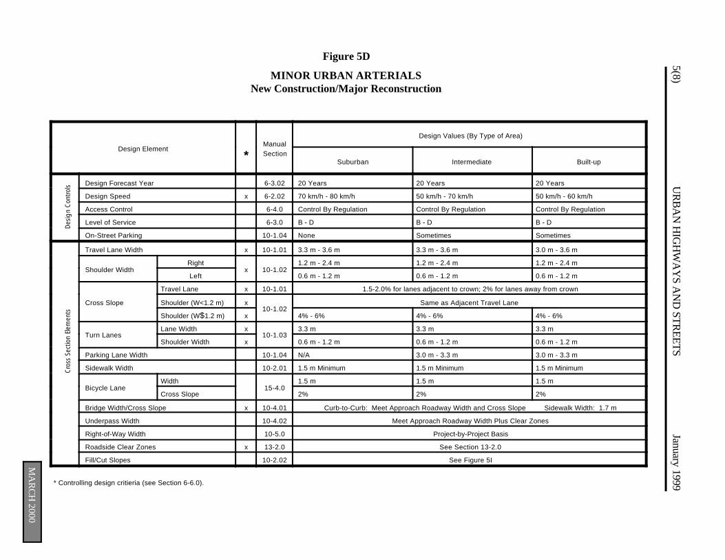
5(8)U
RB
AN
HIG
HW
AY
S AN
D STR
EETSJanuary 1999
MA
RC
H 2000
Des
ign
Con
trol
sC
ross
Sec
tion
Elem
ents
Figure 5D
MINOR URBAN ARTERIALSNew Construction/Major Reconstruction
Design Element*
ManualSection
Design Values (By Type of Area)
Suburban Intermediate Built-up
Design Forecast Year 6-3.02 20 Years 20 Years 20 Years
Design Speed x 6-2.02 70 km/h - 80 km/h 50 km/h - 70 km/h 50 km/h - 60 km/h
Access Control 6-4.0 Control By Regulation Control By Regulation Control By Regulation
Level of Service 6-3.0 B - D B - D B - D
On-Street Parking 10-1.04 None Sometimes Sometimes
Travel Lane Width x 10-1.01 3.3 m - 3.6 m 3.3 m - 3.6 m 3.0 m - 3.6 m
Shoulder WidthRight
x 10-1.021.2 m - 2.4 m 1.2 m - 2.4 m 1.2 m - 2.4 m
Left 0.6 m - 1.2 m 0.6 m - 1.2 m 0.6 m - 1.2 m
Cross Slope
Travel Lane x 10-1.01 1.5-2.0% for lanes adjacent to crown; 2% for lanes away from crown
Shoulder (W<1.2 m) x10-1.02
Same as Adjacent Travel Lane
Shoulder (W$1.2 m) x 4% - 6% 4% - 6% 4% - 6%
Turn LanesLane Width x
10-1.033.3 m 3.3 m 3.3 m
Shoulder Width x 0.6 m - 1.2 m 0.6 m - 1.2 m 0.6 m - 1.2 m
Parking Lane Width 10-1.04 N/A 3.0 m - 3.3 m 3.0 m - 3.3 m
Sidewalk Width 10-2.01 1.5 m Minimum 1.5 m Minimum 1.5 m Minimum
Bicycle LaneWidth
15-4.01.5 m 1.5 m 1.5 m
Cross Slope 2% 2% 2%
Bridge Width/Cross Slope x 10-4.01 Curb-to-Curb: Meet Approach Roadway Width and Cross Slope Sidewalk Width: 1.7 m
Underpass Width 10-4.02 Meet Approach Roadway Width Plus Clear Zones
Right-of-Way Width 10-5.0 Project-by-Project Basis
Roadside Clear Zones x 13-2.0 See Section 13-2.0
Fill/Cut Slopes 10-2.02 See Figure 5I
* Controlling design critieria (see Section 6-6.0).

Alig
nmen
t El
emen
ts
January 1999U
RB
AN
HIG
HW
AY
S AN
D STR
EETS5(9)
Figure 5D (Continued)
MINOR URBAN ARTERIALSNew Construction/Major Reconstruction
Design Element * ManualSection
Design Values (Based on Design Speed)
80 km/h 70 km/h 60 km/h 50 km/h
Stopping Sight Distance x 7-1.0 115 m - 140 m 95 m - 115 m 75 m - 85 m 60 m - 65 m
Decision SightDistance
Maneuver7-2.0
U: 315 m SU: 275 m U: 275 m SU: 240 m U: 235 m SU: 205 m U: 200 m SU: 160 m
Stop 300 m 250 m 205 m 160 m
Minimum Radius x8-2.02/8-3.02
255 m(e = 6%)
190 m(e = 4%)
130 m(e = 4%)
80 m(e = 4%)
Superelevationemax 8-2.02/
8-3.02
6.0% 4.0% 4.0% 4.0%
Rate x See Fig. 8-2A See Figure 8-3C
Horizontal Sight Distance 8-2.04 See Section 8-2.04
Maximum Grade x 9-2.03 7% 7% 8% 9%
Minimum Grade 9-2.03 0.5%
Vertical Curvature(K-Value)
Crest 9-3.02 33 - 49 23 - 33 14 - 18 9 - 11
Sag 9-3.03 26 - 33 20 - 26 15 - 18 11 - 13
Minimum VerticalClearance:Arterial Under ...
New Highway Bridge x
9-4.0
5.05 m
Existing HighwayBridge
x 4.35 m
Minimum Vertical Clearance(Arterial over Railroad)
x 9-4.0Electrified: 6.858 mAll Others: 6.248 m
* Controlling design criteria (see Section 6-6.0) U: Urban SU: Suburban
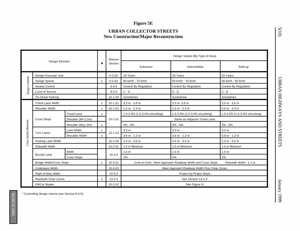
5(10)U
RB
AN
HIG
HW
AY
S AN
D STR
EETSJanuary 1999
MA
RC
H 2000
Des
ign
Con
trol
sC
ross
Sec
tion
Elem
ents
Figure 5E
URBAN COLLECTOR STREETSNew Construction/Major Reconstruction
Design Element*
ManualSection
Design Values (By Type of Area)
Suburban Intermediate Built-up
Design Forecast Year 6-3.02 20 Years 20 Years 20 Years
Design Speed x 6-2.02 60 km/h - 70 km/h 50 km/h - 70 km/h 50 km/h - 60 km/h
Access Control 6-4.0 Control By Regulation Control By Regulation Control By Regulation
Level of Service 6-3.0 C - D C - D C - D
On-Street Parking 10-1.04 Sometimes Sometimes Sometimes
Travel Lane Width x 10-1.01 3.3 m - 3.6 m 3.3 m -3.6 m 3.0 m - 3.6 m
Shoulder Width x 10-1.02 1.2 m - 2.4 m 1.2 m - 2.4 m 0.6 m - 2.4 m
Cross Slope
Travel Lane x
10-1.01
1.5-2.0% (1.5-3.0% w/curbing) 1.5-2.0% (1.5-3.0% w/curbing) 1.5-2.0% (1.5-3.0% w/curbing)
Shoulder (W<1.2m) Same as Adjacent Travel Lane
Shoulder (W>1.2m) x 4% - 6% 4% - 6% 4% - 6%
Turn LanesLane Width x
10-1.033.3 m 3.3 m 3.3 m
Shoulder Width x 0.6 m - 1.2 m 0.6 m - 1.2 m 0.6 m - 1.2 m
Parking Lane Width 10-1.04 2.4 m - 3.0 m 2.4 m - 3.0 m 2.4 m - 3.0 m
Sidewalk Width 10-2.01 1.5 m Minimum 1.5 m Minimum 1.5 m Minimum
Bicycle LaneWidth
15-4.01.5 m 1.5 m 1.5 m
Cross Slope 2% 2% 2%
Bridge Width/Cross Slope x 10-4.01 Curb-to-Curb: Meet Approach Roadway Width and Cross Slope Sidewalk Width: 1.7 m
Underpass Width 10-4.02 Meet Approach Roadway Width Plus Clear Zones
Right-of-Way Width 10-5.0 Project-by-Project Basis
Roadside Clear Zones x 13-2.0 See Section 13-2.0
Fill/Cut Slopes 10-2.02 See Figure 5I
* Controlling design criteria (see Section 6-6.0).
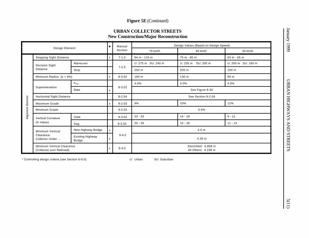
Alig
nmen
t El
emen
ts
January 1999U
RB
AN
HIG
HW
AY
S AN
D STR
EETS5(11)
Figure 5E (Continued)
URBAN COLLECTOR STREETSNew Construction/Major Reconstruction
Design Element * ManualSection
Design Values (Based on Design Speed)
70 km/h 60 km/h 50 km/h
Stopping Sight Distance x 7-1.0 94 m - 115 m 75 m - 85 m 60 m - 65 m
Decision SightDistance
Maneuver7-2.0
U: 275 m SU: 240 m U: 235 m SU: 205 m U: 200 m SU: 160 m
Stop 250 m 205 m 160 m
Minimum Radius (e = 4%) x 8-3.02 190 m 130 m 80 m
Superelevationemax
8-3.024.0% 4.0% 4.0%
Rate x See Figure 8-3C
Horizontal Sight Distance 8-2.04 See Section 8-2.04
Maximum Grade x 9-2.03 9% 10% 11%
Minimum Grade 9-2.03 0.5%
Vertical Curvature(K-Value)
Crest 9-3.02 23 - 33 14 - 18 9 - 11
Sag 9-3.03 20 - 26 15 - 18 11 - 13
Minimum VerticalClearance:Collector Under ...
New Highway Bridge x
9-4.0
4.5 m
Existing HighwayBridge x 4.35 m
Minimum Vertical Clearance(Collector over Railroad) x 9-4.0
Electrified: 6.858 mAll Others: 6.248 m
* Controlling design criteria (see Section 6-6.0) U: Urban SU: Suburban
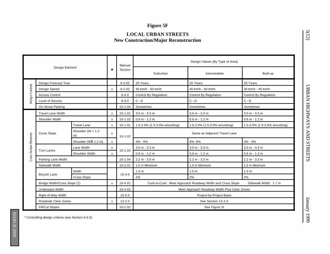
5(12)U
RB
AN
HIG
HW
AY
S AN
D STR
EETSJanuary 1999
MA
RC
H 2000
Des
ign
Con
trol
sC
ross
Sec
tion
Elem
ents
Figure 5F
LOCAL URBAN STREETSNew Construction/Major Reconstruction
Design Element*
ManualSection
Design Values (By Type of Area)
Suburban Intermediate Built-up
Design Forecast Year 6-3.02 20 Years 20 Years 20 Years
Design Speed x 6-2.02 40 km/h - 50 km/h 40 km/h - 50 km/h 30 km/h - 40 km/h
Access Control 6-4.0 Control By Regulation Control By Regulation Control By Regulation
Level of Service 6-3.0 C - D C - D C - D
On-Street Parking 10-1.04 Sometimes Sometimes Sometimes
Travel Lane Width x 10-1.01 3.0 m - 3.3 m 3.0 m - 3.3 m 3.0 m - 3.3 m
Shoulder Width x 10-1.02 0.6 m - 1.2 m 0.6 m - 1.2 m 0.6 m - 1.2 m
Cross Slope
Travel Lane x 10-1.01 1.5-2.0% (1.5-3.0% w/curbing) 1.5-2.0% (1.5-3.0% w/curbing) 1.5-2.0% (1.5-3.0% w/curbing)
Shoulder (W < 1.2m)
x10-1.02
Same as Adjacent Travel Lane
Shoulder (W$ 1.2 m) x 4% - 6% 4% -6% 4% - 6%
Turn LanesLane Width x
10-1.033.0 m - 3.3 m 3.0 m - 3.3 m 3.0 m - 3.3 m
Shoulder Width x 0.6 m - 1.2 m 0.6 m - 1.2 m 0.6 m - 1.2 m
Parking Lane Width 10-1.04 2.2 m - 3.0 m 2.2 m - 3.3 m 2.2 m - 3.3 m
Sidewalk Width 10-2.01 1.5 m Minimum 1.5 m Minimum 1.5 m Minimum
Bicycle Lane Width
15-4.01.5 m 1.5 m 1.5 m
Cross Slope 2% 2% 2%
Bridge Width/Cross Slope (1) x 10-4.01 Curb-to-Curb: Meet Approach Roadway Width and Cross Slope Sidewalk Width: 1.7 m
Underpass Width 10-4.02 Meet Approach Roadway Width Plus Clear Zones
Right-of-Way Width 10-5.0 Project-by-Project Basis
Roadside Clear Zones x 13-2.0 See Section 13-2.0
Fill/Cut Slopes 10-2.02 See Figure 5I
* Controlling design critieria (see Section 6-6.0).
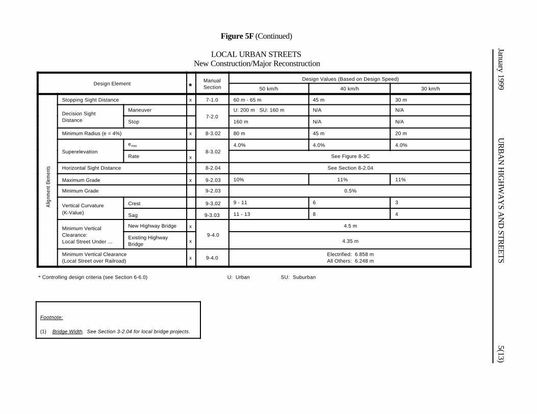
January 1999U
RB
AN
HIG
HW
AY
S AN
D STR
EETS5(13)
Alig
nmen
t El
emen
ts
Footnote:
(1) Bridge Width. See Section 3-2.04 for local bridge projects.
Figure 5F (Continued)
LOCAL URBAN STREETSNew Construction/Major Reconstruction
Design Element *ManualSection
Design Values (Based on Design Speed)
50 km/h 40 km/h 30 km/h
Stopping Sight Distance x 7-1.0 60 m - 65 m 45 m 30 m
Decision SightDistance
Maneuver7-2.0
U: 200 m SU: 160 m N/A N/A
Stop 160 m N/A N/A
Minimum Radius (e = 4%) x 8-3.02 80 m 45 m 20 m
Superelevation
emax
8-3.024.0% 4.0% 4.0%
Rate x See Figure 8-3C
Horizontal Sight Distance 8-2.04 See Section 8-2.04
Maximum Grade x 9-2.03 10% 11% 11%
Minimum Grade 9-2.03 0.5%
Vertical Curvature(K-Value)
Crest 9-3.02 9 - 11 6 3
Sag 9-3.03 11 - 13 8 4
Minimum VerticalClearance:Local Street Under ...
New Highway Bridge x
9-4.0
4.5 m
Existing HighwayBridge
x 4.35 m
Minimum Vertical Clearance(Local Street over Railroad)
x 9-4.0Electrified: 6.858 mAll Others: 6.248 m
* Controlling design criteria (see Section 6-6.0) U: Urban SU: Suburban
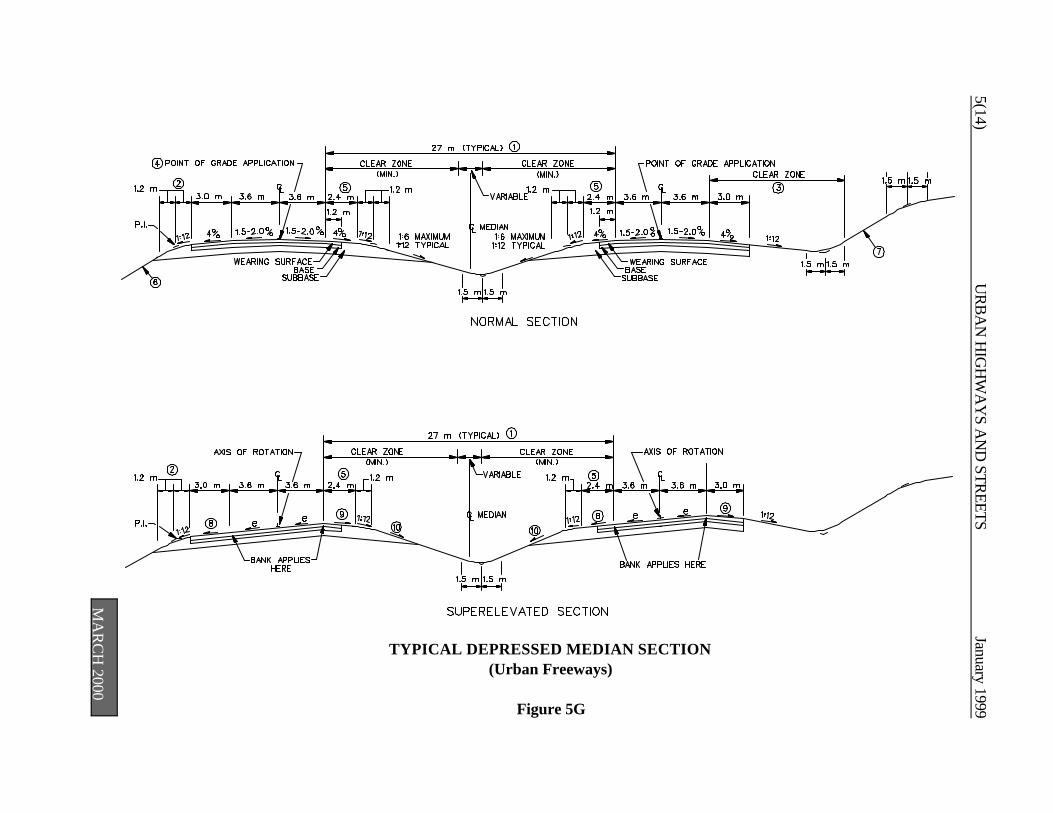
5(14)U
RB
AN
HIG
HW
AY
S AN
D STR
EETSJanuary 1999
TYPICAL DEPRESSED MEDIAN SECTION(Urban Freeways)
Figure 5G
MA
RC
H 2000
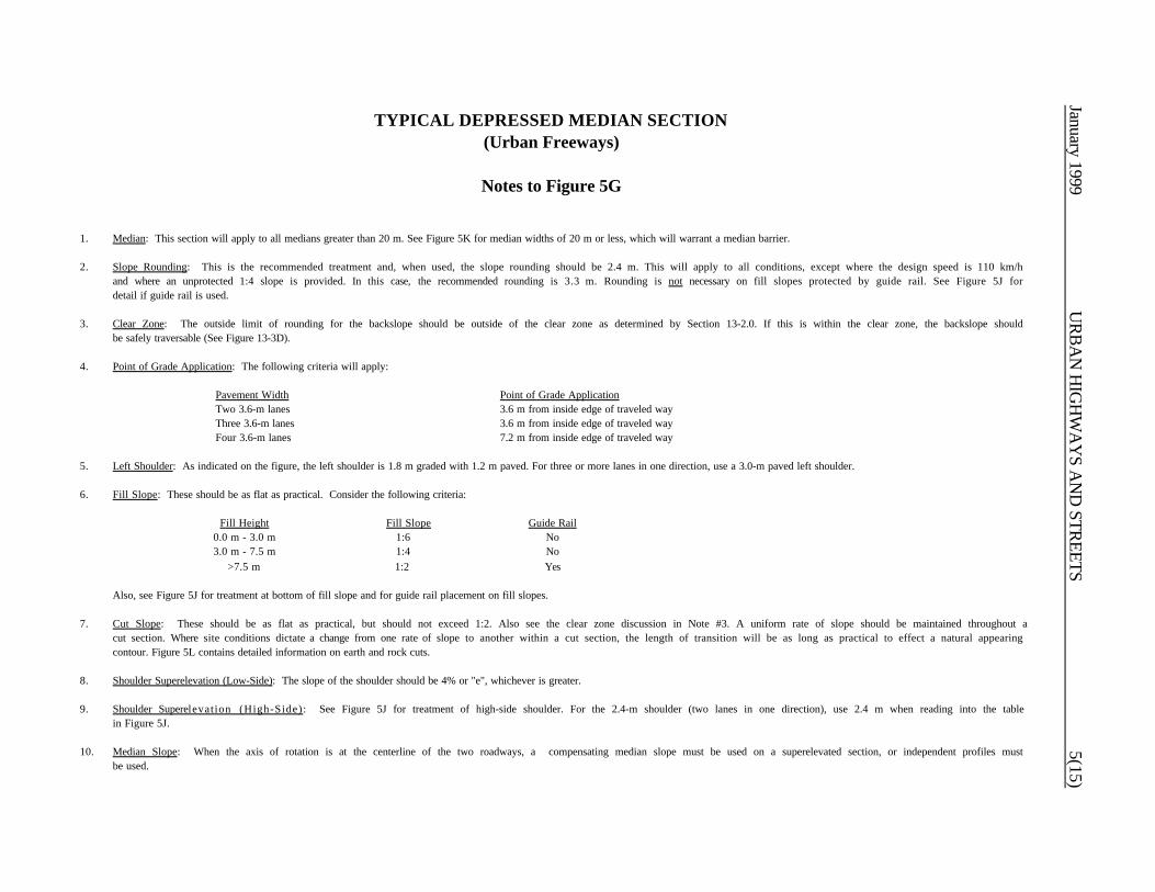
January 1999U
RB
AN
HIG
HW
AY
S AN
D STR
EETS5(15)
TYPICAL DEPRESSED MEDIAN SECTION(Urban Freeways)
Notes to Figure 5G
1. Median: This section will apply to all medians greater than 20 m. See Figure 5K for median widths of 20 m or less, which will warrant a median barrier.
2. Slope Rounding: This is the recommended treatment and, when used, the slope rounding should be 2.4 m. This will apply to all conditions, except where the design speed is 110 km/hand where an unprotected 1:4 slope is provided. In this case, the recommended rounding is 3.3 m. Rounding is not necessary on fill slopes protected by guide rail. See Figure 5J fordetail if guide rail is used.
3. Clear Zone: The outside limit of rounding for the backslope should be outside of the clear zone as determined by Section 13-2.0. If this is within the clear zone, the backslope shouldbe safely traversable (See Figure 13-3D).
4. Point of Grade Application: The following criteria will apply:
Pavement Width Point of Grade ApplicationTwo 3.6-m lanes 3.6 m from inside edge of traveled wayThree 3.6-m lanes 3.6 m from inside edge of traveled wayFour 3.6-m lanes 7.2 m from inside edge of traveled way
5. Left Shoulder: As indicated on the figure, the left shoulder is 1.8 m graded with 1.2 m paved. For three or more lanes in one direction, use a 3.0-m paved left shoulder.
6. Fill Slope: These should be as flat as practical. Consider the following criteria:
Fill Height Fill Slope Guide Rail0.0 m - 3.0 m 1:6 No3.0 m - 7.5 m 1:4 No
>7.5 m 1:2 Yes
Also, see Figure 5J for treatment at bottom of fill slope and for guide rail placement on fill slopes.
7. Cut Slope: These should be as flat as practical, but should not exceed 1:2. Also see the clear zone discussion in Note #3. A uniform rate of slope should be maintained throughout acut section. Where site conditions dictate a change from one rate of slope to another within a cut section, the length of transition will be as long as practical to effect a natural appearingcontour. Figure 5L contains detailed information on earth and rock cuts.
8. Shoulder Superelevation (Low-Side): The slope of the shoulder should be 4% or "e", whichever is greater.
9. Shoulder Superelevation (High-Side): See Figure 5J for treatment of high-side shoulder. For the 2.4-m shoulder (two lanes in one direction), use 2.4 m when reading into the tablein Figure 5J.
10. Median Slope: When the axis of rotation is at the centerline of the two roadways, a compensating median slope must be used on a superelevated section, or independent profiles mustbe used.
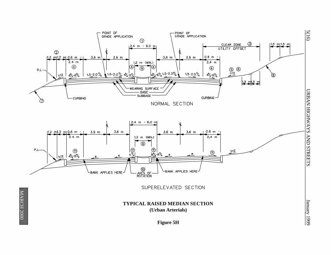
5(16)U
RB
AN
HIG
HW
AY
S AN
D STR
EETSJanuary 1999
TYPICAL RAISED MEDIAN SECTION(Urban Arterials)
Figure 5H
MA
RC
H 2000
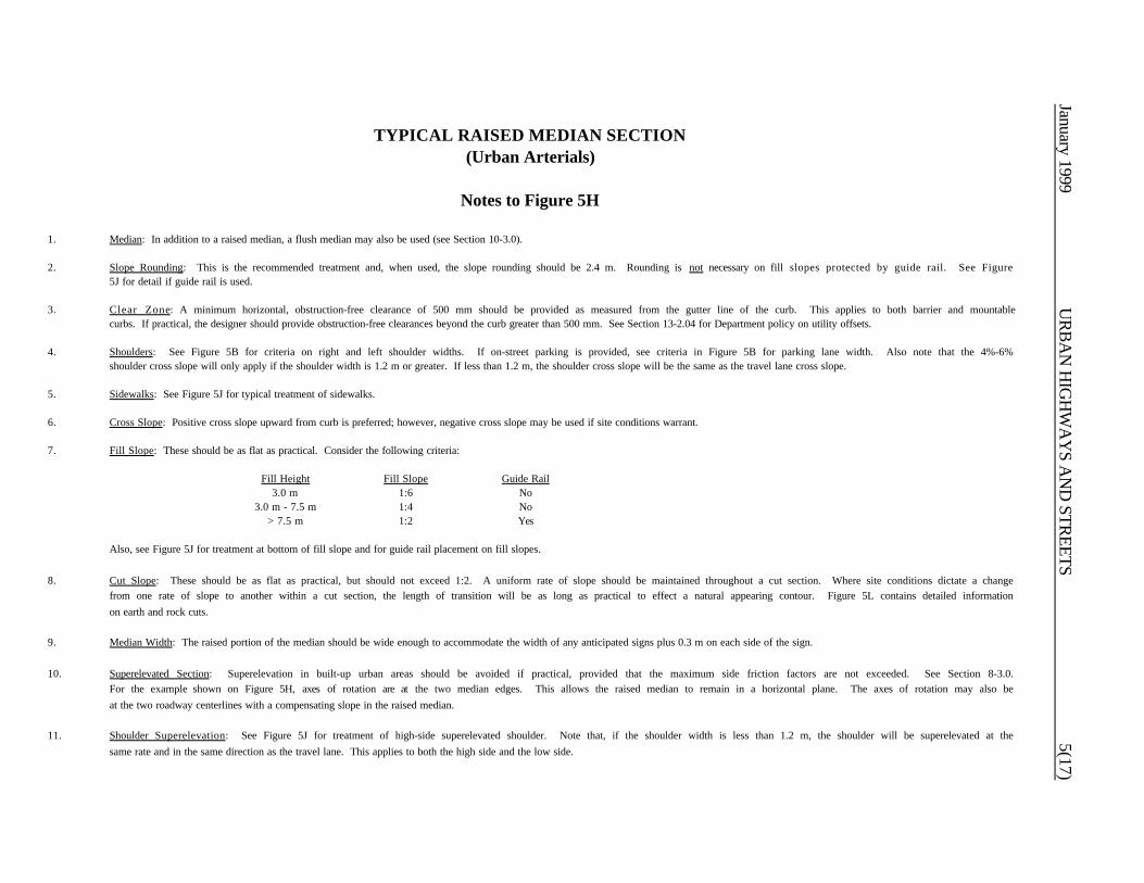
January 1999U
RB
AN
HIG
HW
AY
S AN
D STR
EETS5(17)
TYPICAL RAISED MEDIAN SECTION(Urban Arterials)
Notes to Figure 5H
1. Median: In addition to a raised median, a flush median may also be used (see Section 10-3.0).
2. Slope Rounding: This is the recommended treatment and, when used, the slope rounding should be 2.4 m. Rounding is not necessary on fill slopes protected by guide rail. See Figure5J for detail if guide rail is used.
3. Clear Zone: A minimum horizontal, obstruction-free clearance of 500 mm should be provided as measured from the gutter line of the curb. This applies to both barrier and mountablecurbs. If practical, the designer should provide obstruction-free clearances beyond the curb greater than 500 mm. See Section 13-2.04 for Department policy on utility offsets.
4. Shoulders: See Figure 5B for criteria on right and left shoulder widths. If on-street parking is provided, see criteria in Figure 5B for parking lane width. Also note that the 4%-6%shoulder cross slope will only apply if the shoulder width is 1.2 m or greater. If less than 1.2 m, the shoulder cross slope will be the same as the travel lane cross slope.
5. Sidewalks: See Figure 5J for typical treatment of sidewalks.
6. Cross Slope: Positive cross slope upward from curb is preferred; however, negative cross slope may be used if site conditions warrant.
7. Fill Slope: These should be as flat as practical. Consider the following criteria:
Fill Height Fill Slope Guide Rail3.0 m 1:6 No
3.0 m - 7.5 m 1:4 No> 7.5 m 1:2 Yes
Also, see Figure 5J for treatment at bottom of fill slope and for guide rail placement on fill slopes.
8. Cut Slope: These should be as flat as practical, but should not exceed 1:2. A uniform rate of slope should be maintained throughout a cut section. Where site conditions dictate a changefrom one rate of slope to another within a cut section, the length of transition will be as long as practical to effect a natural appearing contour. Figure 5L contains detailed informationon earth and rock cuts.
9. Median Width: The raised portion of the median should be wide enough to accommodate the width of any anticipated signs plus 0.3 m on each side of the sign.
10. Superelevated Section: Superelevation in built-up urban areas should be avoided if practical, provided that the maximum side friction factors are not exceeded. See Section 8-3.0.For the example shown on Figure 5H, axes of rotation are at the two median edges. This allows the raised median to remain in a horizontal plane. The axes of rotation may also beat the two roadway centerlines with a compensating slope in the raised median.
11. Shoulder Superelevation: See Figure 5J for treatment of high-side superelevated shoulder. Note that, if the shoulder width is less than 1.2 m, the shoulder will be superelevated at thesame rate and in the same direction as the travel lane. This applies to both the high side and the low side.

5(18)U
RB
AN
HIG
HW
AY
S AN
D STR
EETSJanuary 1999
TYPICAL TWO-LANE SECTION(Urban Arterial/Collector/Local Street)
Figure 5I
MA
RC
H 2000
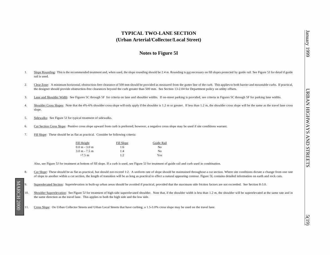
January 1999U
RB
AN
HIG
HW
AY
S AN
D STR
EETS5(19)
TYPICAL TWO-LANE SECTION(Urban Arterial/Collector/Local Street)
Notes to Figure 5I
1. Slope Rounding: This is the recommended treatment and, when used, the slope rounding should be 2.4 m. Rounding is not necessary on fill slopes protected by guide rail. See Figure 5J for detail if guiderail is used.
2. Clear Zone: A minimum horizontal, obstruction-free clearance of 500 mm should be provided as measured from the gutter line of the curb. This applies to both barrier and mountable curbs. If practical,the designer should provide obstruction-free clearances beyond the curb greater than 500 mm. See Section 13-2.04 for Department policy on utility offsets.
3. Lane and Shoulder Width: See Figures 5C through 5F for criteria on lane and shoulder widths. If on-street parking is provided, see criteria in Figures 5C through 5F for parking lane widths.
4. Shoulder Cross Slopes: Note that the 4%-6% shoulder cross slope will only apply if the shoulder is 1.2 m or greater. If less than 1.2 m, the shoulder cross slope will be the same as the travel lane crossslope.
5. Sidewalks: See Figure 5J for typical treatment of sidewalks.
6. Cut Section Cross Slope: Positive cross slope upward from curb is preferred; however, a negative cross slope may be used if site conditions warrant.
7. Fill Slope: These should be as flat as practical. Consider he following criteria:
Fill Height Fill Slope Guide Rail0.0 m - 3.0 m 1:6 No3.0 m - 7.5 m 1:4 No
>7.5 m 1:2 Yes
Also, see Figure 5J for treatment at bottom of fill slope. If a curb is used, see Figure 5J for treatment of guide rail and curb used in combination.
8. Cut Slope: These should be as flat as practical, but should not exceed 1:2. A uniform rate of slope should be maintained throughout a cut section. Where site conditions dictate a change from one rateof slope to another within a cut section, the length of transition will be as long as practical to effect a natural appearing contour. Figure 5L contains detailed information on earth and rock cuts.
9. Superelevated Section: Superelevation in built-up urban areas should be avoided if practical, provided that the maximum side friction factors are not exceeded. See Section 8-3.0.
10. Shoulder Superelevation: See Figure 5J for treatment of high-side superelevated shoulder. Note that, if the shoulder width is less than 1.2 m, the shoulder will be superelevated at the same rate and inthe same direction as the travel lane. This applies to both the high side and the low side.
11. Cross Slope: On Urban Collector Streets and Urban Local Streets that have curbing, a 1.5-3.0% cross slope may be used on the travel lane.
MA
RC
H 2000

5(20)U
RB
AN
HIG
HW
AY
S AN
D STR
EETSJanuary 1999
MISCELLANEOUS DETAILS
VARIOUS CLASSES
Figure 5J
MA
RC
H 2000
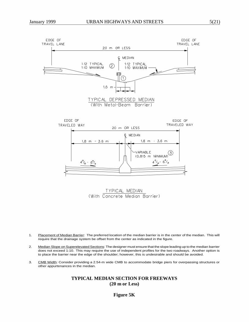
January 1999 URBAN HIGHWAYS AND STREETS 5(21)
1. Placement of Median Barrier: The preferred location of the median barrier is in the center of the median. This willrequire that the drainage system be offset from the center as indicated in the figure.
2. Median Slope on Superelevated Sections: The designer must ensure that the slope leading up to the median barrierdoes not exceed 1:10. This may require the use of independent profiles for the two roadways. Another option isto place the barrier near the edge of the shoulder; however, this is undesirable and should be avoided.
3. CMB Width: Consider providing a 2.54-m wide CMB to accommodate bridge piers for overpassing structures orother appurtenances in the median.
TYPICAL MEDIAN SECTION FOR FREEWAYS(20 m or Less)
Figure 5K
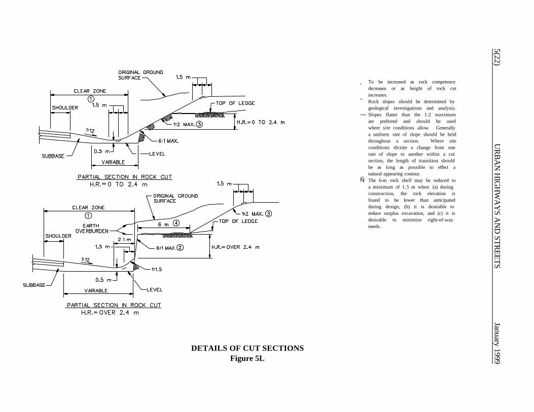
5(22)U
RB
AN
HIG
HW
AY
S AN
D STR
EETSJanuary 1999
Î To be increased as rock competencedecreases or as height of rock cutincreases.
Ï Rock slopes should be determined bygeological investigations and analysis.
Ð Slopes flatter than the 1:2 maximumare preferred and should be usedwhere site conditions allow. Generallya uniform rate of slope should be heldthroughout a section. Where siteconditions dictate a change from onerate of slope to another within a cutsection, the length of transition shouldbe as long as possible to effect anatural appearing contour.
Ñ The 6-m rock shelf may be reduced toa minimum of 1.5 m when: (a) duringconstruction, the rock elevation isfound to be lower than anticipatedduring design, (b) it is desirable toreduce surplus excavation, and (c) it isdesirable to minimize right-of-wayneeds.
DETAILS OF CUT SECTIONSFigure 5L

January 1999U
RB
AN
HIG
HW
AY
S AN
D STR
EETS5(23)
Note: See Section 10-6.0 for a discussion on this typical section.
TYPICAL SECTION FOR URBAN FREEWAYS(High-Volume/Incident Management Freeways)
Figure 5M
MA
RC
H 2000
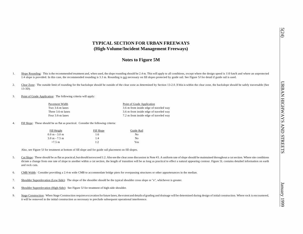
5(24)U
RB
AN
HIG
HW
AY
S AN
D STR
EETSJanuary 1999
TYPICAL SECTION FOR URBAN FREEWAYS(High-Volume/Incident Management Freeways)
Notes to Figure 5M
1. Slope Rounding: This is the recommended treatment and, when used, the slope rounding should be 2.4 m. This will apply to all conditions, except where the design speed is 110 km/h and where an unprotected1:4 slope is provided. In this case, the recommended rounding is 3.3 m. Rounding is not necessary on fill slopes protected by guide rail. See Figure 5J for detail if guide rail is used.
2. Clear Zone: The outside limit of rounding for the backslope should be outside of the clear zone as determined by Section 13-2.0. If this is within the clear zone, the backslope should be safely traversable (See13-3D).
3. Point of Grade Application: The following criteria will apply:
Pavement Width Point of Grade ApplicationTwo 3.6-m lanes 3.6 m from inside edge of traveled wayThree 3.6-m lanes 3.6 m from inside edge of traveled wayFour 3.6-m lanes 7.2 m from inside edge of traveled way
4. Fill Slope: These should be as flat as practical. Consider the following criteria:
Fill Height Fill Slope Guide Rail0.0 m - 3.0 m 1:6 No3.0 m - 7.5 m 1:4 No
>7.5 m 1:2 Yes
Also, see Figure 5J for treatment at bottom of fill slope and for guide rail placement on fill slopes.
5. Cut Slope: These should be as flat as practical, but should not exceed 1:2. Also see the clear zone discussion in Note #3. A uniform rate of slope should be maintained throughout a cut section. Where site conditionsdictate a change from one rate of slope to another within a cut section, the length of transition will be as long as practical to effect a natural appearing contour. Figure 5L contains detailed information on earthand rock cuts.
6. CMB Width: Consider providing a 2.4-m wide CMB to accommodate bridge piers for overpassing structures or other appurtenances in the median.
7. Shoulder Superelevation (Low-Side): The slope of the shoulder should be the typical shoulder cross slope or "e", whichever is greater.
8. Shoulder Superelevation (High-Side): See Figure 5J for treatment of high-side shoulder.
9. Stage Construction: When Stage Construction requires excavation for future lanes, the extent and details of grading and drainage will be determined during design of initial construction. Where rock is encountered,it will be removed in the initial construction as necessary to preclude subsequent operational interference.
January 1999 DESIGN CONTROLS 6-i
Chapter Six
DESIGN CONTROLS
Table of Contents
Page
6-1.0 HIGHWAY SYSTEMS . . . . . . . . . . . . . . . . . . . . . . . . . . . . . . . . . . . . . . . . . . . . . . 6-1(1)
6-1.01 Functional Classification System . . . . . . . . . . . . . . . . . . . . . . . . . . . . . . . . 6-1(1)
6-1.01.01 Arterials . . . . . . . . . . . . . . . . . . . . . . . . . . . . . . . . . . . . . . . . 6-1(1) 6-1.01.02 Collectors . . . . . . . . . . . . . . . . . . . . . . . . . . . . . . . . . . . . . . . 6-1(2) 6-1.01.03 Local Roads and Streets . . . . . . . . . . . . . . . . . . . . . . . . . . . . 6-1(2)
6-1.02 Federal-Aid System . . . . . . . . . . . . . . . . . . . . . . . . . . . . . . . . . . . . . . . . . 6-1(2)
6-1.02.01 National Highway System . . . . . . . . . . . . . . . . . . . . . . . . . . . . 6-1(3) 6-1.02.02 Surface Transportation System . . . . . . . . . . . . . . . . . . . . . . . . 6-1(3) 6-1.02.03 Bridge Replacement and Rehabilitation Program . . . . . . . . . . . 6-1(4)
6-1.03 Classification by Type of Area . . . . . . . . . . . . . . . . . . . . . . . . . . . . . . . . . 6-1(4)
6-1.03.01 Rural Highways and Roads . . . . . . . . . . . . . . . . . . . . . . . . . . . 6-1(4) 6-1.03.02 Urban Highways and Streets . . . . . . . . . . . . . . . . . . . . . . . . . 6-1(5)
6-2.0 SPEED . . . . . . . . . . . . . . . . . . . . . . . . . . . . . . . . . . . . . . . . . . . . . . . . . . . . . . . . . . . 6-2(1)
6-2.01 Definitions . . . . . . . . . . . . . . . . . . . . . . . . . . . . . . . . . . . . . . . . . . . . . . . . 6-2(1) 6-2.02 Design Speed . . . . . . . . . . . . . . . . . . . . . . . . . . . . . . . . . . . . . . . . . . . . . . 6-2(2) 6-2.03 Posted Speed Limit . . . . . . . . . . . . . . . . . . . . . . . . . . . . . . . . . . . . . . . . . 6-2(3)
6-3.0 HIGHWAY CAPACITY . . . . . . . . . . . . . . . . . . . . . . . . . . . . . . . . . . . . . . . . . . . . . 6-3(1)
6-3.01 Definitions . . . . . . . . . . . . . . . . . . . . . . . . . . . . . . . . . . . . . . . . . . . . . . . . 6-3(1) 6-3.02 Selection of Design Hourly Volume . . . . . . . . . . . . . . . . . . . . . . . . . . . . . . 6-3(2) 6-3.03 Capacity Analyses . . . . . . . . . . . . . . . . . . . . . . . . . . . . . . . . . . . . . . . . . . 6-3(3)
6-ii DESIGN CONTROLS January 1999
Table of Contents(Continued)
Page
6-4.0 ACCESS CONTROL . . . . . . . . . . . . . . . . . . . . . . . . . . . . . . . . . . . . . . . . . . . . . . . . 6-4(1)
6-5.0 PROJECT SCOPE OF WORK . . . . . . . . . . . . . . . . . . . . . . . . . . . . . . . . . . . . . . . . 6-5(1)
6-5.01 Description . . . . . . . . . . . . . . . . . . . . . . . . . . . . . . . . . . . . . . . . . . . . . . . 6-5(1)
6-5.01.01 New Construction . . . . . . . . . . . . . . . . . . . . . . . . . . . . . . . . . 6-5(1) 6-5.01.02 4R (Freeways) . . . . . . . . . . . . . . . . . . . . . . . . . . . . . . . . . . . . 6-5(2) 6-5.01.03 Major Reconstruction (Non-Freeways) . . . . . . . . . . . . . . . . . 6-5(3) 6-5.01.04 3R (Non-Freeways) . . . . . . . . . . . . . . . . . . . . . . . . . . . . . . . . 6-5(5) 6-5.01.05 Spot Improvements . . . . . . . . . . . . . . . . . . . . . . . . . . . . . . . . 6-5(7)
6-5.02 Procedures . . . . . . . . . . . . . . . . . . . . . . . . . . . . . . . . . . . . . . . . . . . . . . . 6-5(8)
6-6.0 EXCEPTIONS TO GEOMETRIC DESIGN CRITERIA . . . . . . . . . . . . . . . . . . . . . 6-6(1)
6-6.01 Department Intent . . . . . . . . . . . . . . . . . . . . . . . . . . . . . . . . . . . . . . . . . . 6-6(1) 6-6.02 Controlling Design Criteria . . . . . . . . . . . . . . . . . . . . . . . . . . . . . . . . . . . . 6-6(1) 6-6.03 Application . . . . . . . . . . . . . . . . . . . . . . . . . . . . . . . . . . . . . . . . . . . . . . . 6-6(3)
6-6.03.01 Project Scope of Work . . . . . . . . . . . . . . . . . . . . . . . . . . . . . 6-6(3) 6-6.03.02 Highway System/Funding Source . . . . . . . . . . . . . . . . . . . . . . 6-6(3)
6-6.04 Procedures for Exceptions . . . . . . . . . . . . . . . . . . . . . . . . . . . . . . . . . . . . 6-6(4)
6-7.0 REFERENCES . . . . . . . . . . . . . . . . . . . . . . . . . . . . . . . . . . . . . . . . . . . . . . . . . . . . . 6-7(1)

January 1999 DESIGN CONTROLS 6-1(1)
Chapter Six
DESIGN CONTROLS
6-1.0 HIGHWAY SYSTEMS
6-1.01 Functional Classification System
The Department's Highway Design Manual is based on the functional classification concept. Chapters Twothrough Five summarize the Department's design criteria for each functional class for rural and urbanhighways and streets and for the Project Scope of Work.
The Department has functionally classified all public highways and streets within Connecticut. To design aproject, the designer should contact the appropriate Department office to determine the predicted functionalclass of the highway or street.
6-1.01.01 Arterials
Arterial highways are characterized by a capacity to quickly move relatively large volumes of traffic. Theyare sometimes deliberately restricted in their service to abutting properties. The arterial functional class issubdivided into principal and minor categories for rural and urban areas:
1. Principal Arterials. In both rural and urban areas, the princ ipal arterials provide the highest trafficvolumes and the greatest trip lengths. The designer should review the project scope of work and theenvironmental documents to determine which of the following principal arterials should be used indesign and identify its corresponding criteria:
a. Freeways. The freeway is the highest level of principal arterials. These facilities are charac-terized by full control of access, high design speeds and a high level of driver comfort andsafety. For these reasons, freeways are considered a special type of highway within thefunctional classification system, and separate design criteria have been developed for thesefacilities.
b. Expressways. These are divided-highway facilities which are characterized by full or partial
control of access. Expressways with full control of access are actually freeways. Partialcontrol of access is characterized by a few at-grade intersections with other public roads,and there may be an occasional private access.
6-1(2) DESIGN CONTROLS January 1999
c. Urban/Rural Arterials. These facilities are usually 2 or 4 lanes with or without a median.Partial control of access is desirable along these facilities. A high level of geometric designis desirable to move the high traffic volumes quickly and efficiently through an area.
2. Minor Arterials. In rural areas, minor arterials will provide a mix of interstate and interregionaltravel service. In urban areas, minor arterials may carry local bus routes and provideintracommunity connections, but they will not, for example, penetrate neighborhoods. Whencompared to the principal arterial system, the minor arterials provide lower travel speeds,accommodate shorter trips and distances and lower traffic volumes but provide more access toproperty.
6-1.01.02 Collectors
Collector routes are characterized by a roughly even distribution of their access and mobility functions.Traffic volumes and speeds will typically be somewhat lower than those of arterials. In rural areas collectorsserve intraregional travel needs and provide connections to the arterial system. All cities and towns withina region will be connected. In urban areas collectors act as intermediate links between the arterial systemand points of origin and destination. Urban collectors typically penetrate residential neighborhoods andcommercial and industrial areas. Local bus routes will often include collector streets.
6-1.01.03 Local Roads and Streets
All public roads and streets not classified as arterials or collectors will have a local classification. Localroads and streets are characterized by their many points of direct access to adjacent properties and theirrelatively minor value in accommodating mobility. Speeds and volumes are usually low and trip distancesshort. Through traffic is often deliberately discouraged.
6-1.02 Federal-Aid System
The Intermodal Surface Transportation Efficiency Act (ISTEA) of 1991 implemented a major realignmentof the Federal-aid system. Traditionally, the system had been divided into Interstate, primary, secondaryand urban Federal-aid systems. Separate categories of Federal funds were available for eligible Federal-aid projects on each system. The following sections briefly describe the Federal-aid system created byISTEA.
January 1999 DESIGN CONTROLS 6-1(3)
6-1.02.01 National Highway System
The National Highway System (NHS) is a system of those highways determined to have the greatestnational importance to transportation, commerce and defense in the United States. It consists of theInterstate highway system, logical additions to the Interstate system, selected other principal arterials, andother facilities which meet the requirements of one of the subsystems within the NHS. The NHS representsapproximately 4%-5% of the total public road kilometers in the United States. Specifically, the NHSincludes the following subsystems (note that a specific highway route may be on more than one subsystem):
1. Interstate. The current Interstate system of highways retains its separate identity within the NHS.There are also provisions to add kilometers to the existing Interstate subsystem.
2. Other Principal Arterials. These are highways in rural and urban areas which provide accessbetween an arterial and a major port, airport, public transportation facility or other intermodaltransportation facility.
3. Strategic Highway Network. This is a network of highways which are important to the UnitedStates' strategic defense policy and which provide defense access, continuity and emergencycapabilities for defense purposes.
4. Major Strategic Highway Network Connectors. These are highways which provide accessbetween major military installations and highways which are part of the Strategic HighwayNetwork.
The 1991 ISTEA has mandated that each State highway agency, in cooperation with other jurisdictionalagencies, develop and implement several management systems. These include management systems forpavements, bridges, traffic congestion, highway safety, public transportation facilities/equipment andintermodal transportation facilities/systems.
6-1.02.02 Surface Transportation Program
The Surface Transportation Program (STP) is a block grant type program that may be used by the Statesand localities for any roads (including NHS facilities) that are not functionally classified as local routes orrural minor collectors. These roads are now collectively referred to as Federal-aid roads. Bridge projectsusing STP funds are not restricted to Federal-aid roads, but may be used on any public road. Transitcapital projects are also eligible under the STP program.

6-1(4) DESIGN CONTROLS January 1999
6-1.02.03 Bridge Replacement and Rehabilitation Program
The Bridge Replacement and Rehabilitation Program (BRRP) has retained its separate identity within theFederal-aid program. BRRP funds are eligible for work on any bridge on any public road regardless ofits functional classification.
6-1.03 Classification by Type of Area
The functional classification system is based on urban or rural designation. For a highly developed Statelike Connecticut, this is not sufficient to determine the appropriate project design. Therefore, the designcriteria in Chapters Two, Four and Five are further divided by the type of area where the project is located.This refinement to the highway design process will allow the designer to better tailor the project to theconstraints of the surrounding environment.
The following sections briefly discuss the classifications by type of area for urban and rural locations. Thedesigner is responsible for determining which type of area is most appropriate for the project under design.
6-1.03.01 Rural Highways and Roads
Chapter Four presents the Department's design criteria for new construction or major reconstruction ofrural highways and roads; Chapter Two presents the criteria for 3R non-freeway projects. Many highwaysin Connecticut are classified as rural but frequently pass through relatively built-up areas. Therefore,Chapters Two and Four present design criteria based on the extent of roadside development. The tablesin the chapters provide criteria for the average number of access points per kilometer per side. Thesecriteria provide some guidance for the designer, but they should not be considered rigid. In addition, thedesigner should consider the following narrative descriptions:
1. Open. This fits the traditional concept of a rural area. The driver has almost total freedom ofmovement and is generally not affected by occasional access points along the highway or road. Forthe purpose of determining the classification, access points will average less than 10 per kilometerper side. Right-of-way is usually not a problem.
2. Low/Moderate Density. The roadside development has increased to a level where the prudentdriver will instinctively reduce his/her speed as compared to an open highway. The driver must bemore alert to the possibility of entering and exiting vehicles, but he/she is still able to maintain a rela-tively high travel speed. The estimated number of access points will average between 10 and 20per kilometer per side. Right-of-way may be difficult to attain.
January 1999 DESIGN CONTROLS 6-1(5)
3. Moderate/High Density. The roadside development has increased to a level which is comparableto a suburban area within an urbanized boundary. The extent of the development will have asignificant impact on the selected travel speed of a prudent driver. Exiting and entering vehicles arefrequent, and traffic signals are typical at major intersections. The estimated number of accesspoints will average greater than 20 per kilometer per side. Right-of-way is usually quite difficult toattain.
6-1.03.02 Urban Highways and Streets
Chapter Five presents the Department's design criteria for new construction or major reconstruction ofurban highways and streets; Chapter Two presents the criteria for 3R non-freeway projects. Eachfunctional classification table is subdivided by the type of area where the project is located. The designershould consider the following descriptions when selecting the applicable type of area:
1. Suburban. These areas are usually located at the fringes of urbanized and small urban areas. Thepredominant character of the surrounding environment is usually residential, but it will also includea considerable number of commercial establishments. There may also be a few industrial parks insuburban areas. On suburban roads and streets, drivers usually have a significant degree offreedom but, nonetheless, they must also devote some of their attention to entering and exitingvehicles. Roadside development is characterized by low to moderate density. Pedestrian activitymay or may not be a significant design factor. Right-of-way is often available for roadwayimprovements.
Local and collector streets in suburban areas are typically located in residential areas, but may alsoserve a commercial area. Posted speed limits typically range between 25 and 40 mph (40 and 70km/h). The majority of intersections will have stop or yield control, but there will be an occasionaltraffic signal. A typical suburban arterial will have strip commercial development and perhaps a fewresidential properties. Posted speed limits usually range between 35 and 50 mph (60 and 80 km/h),and there will usually be a few signalized intersections along the arterial.
2. Intermediate. As its name implies, intermediate areas fall between suburban and built-up areas. Thesurrounding environment may be either residential, commercial or industrial or some combinationof these. On roads and streets in intermediate areas, the extent of roadside development will havea significant impact on the selected speeds of drivers. The increasing frequency of intersections isalso a major control on average travel speeds. Pedestrian activity has now become a significantdesign consideration, and sidewalks and cross walks at intersections are common. The availableright-of-way will often restrict the practical extent of roadway improvements.

6-1(6) DESIGN CONTROLS January 1999
Local and collector streets in intermediate areas typically have posted speed limits between 25 and35 mph (40 and 60 km/h). The frequency of signalized intersections has increased substantiallywhen compared to suburban areas. An arterial in an intermediate area will often have intensivecommercial development along its roadside. Posted speed limits range between 30 and 40 mph(50 and 70 km/h). These arterials typically have several signalized intersections per kilometer.
3. Built-up. These areas normally refer to the central business district within an urbanized or smallurban area. The roadside development has a high density and is often commercial. However, asubstantial number of roads and streets in built-up areas pass through a high-density, residentialenvironment (e.g., apartment complexes, row houses). Access to property is the primary functionof the road network in built-up areas; the average driver rarely passes through a built-up area formobility purposes. Pedestrian considerations may be as important as vehicular considerations,especially at intersections. Right-of-way for roadway improvements is usually not available.
Because of the high density of development in built-up areas, the distinction between the functionalclasses (local, collector or arterial) becomes less important when considering signalization andspeeds. The primary distinction among the three functional classes is often the relative trafficvolumes and, therefore, the number of lanes. As many as half the intersections may be signalized;posted speed limits typically range between 25 and 35 mph (40 and 60 km/h).
January 1999 DESIGN CONTROLS 6-2(1)
6-2.0 SPEED
6-2.01 Definitions
1. Design Speed. Design speed is the maximum safe speed that can be maintained over a specifiedsection of highway when conditions are so favorable that the design features of the highway govern.A design speed is selected for each project which will establish criteria for several design elementsincluding horizontal and vertical curvature, superelevation and sight distance.
2. Low Speed. For geometric design applications, low speed is defined as 70 km/h or less.
3. High Speed. For geometric design applications, high speed is defined as greater than 70 km/h.
4. Average Running Speed. Running speed is the average speed of a vehicle over a specified sectionof highway. It is equal to the distance traveled divided by the running time (the time the vehicle isin motion). The average running speed is the distance summation for all vehicles divided by therunning time summation for all vehicles.
5. Average Travel Speed. Average travel speed is the distance summation for all vehicles divided bythe total time summation for all vehicles. (Note: Average running speed only includes the time thevehicle is in motion. Therefore, on uninterrupted flow facilities which are not congested, averagerunning speed and average travel speed are equal.)
6. Operating Speed. Operating speed, as defined by AASHTO, is the highest overall speed at whicha driver can safely travel a given highway under favorable weather conditions and prevailing trafficconditions while at no time exceeding the design speed. Therefore, for low-volume conditions,operating speed equals design speed. The designer should note that this term has little or no usagein geometric design.
7. 85th-Percentile Speed. The 85th-percentile speed is the speed below which 85 percent of vehiclestravel on a given highway. The most common application of the value is its use as one of thefactors, and usually the most important factor, for determining the posted, regulatory speed limitof a highway section. In most cases, field measurements for the 85th-percentile speed will beconducted during off-peak hours when drivers are free to select their desired speed.
6-2(2) DESIGN CONTROLS January 1999
6-2.02 Design Speed
Design speed, perhaps more so than any other design control, will have a major impact on all facets ofgeometric design. Many design elements, such as horizontal and vertical curvature, superelevation and sightdistances, are directly dependent on the design speed; i.e., the selected design speed is used directly in theequations for these geometric design elements. Other features, such as lane and shoulder width and clearzones, logically vary with design speed but are not a direct function of the design speed.
Chapters Four and Five present the minimum design speeds for new construction and major reconstruction.The design speed will vary according to functional classification, urban/rural location and type of area.Chapter Two presents the Department's policy for determining the design speed on 3R non-freewayprojects. Design speeds are selected at 10-km/h increments.
The following should be evaluated when determining the project design speed:
1. Balance. The selected design speed should be a reasonable balance between topography, urbanor rural character, and the functional use of the highway. The designer must weigh the benefits ofa desired degree of safety, mobility and efficiency against the environmental, right-of-way and costimpacts.
2. Driver Expectancy. The element of driver expectancy should be considered when selecting thedesign speed. The driver expects to be able to drive at certain maximum speeds based on thefunctional and rural or urban character of the highway. Therefore, the design speed should fit thetravel desires and habits of the great majority of drivers. Driver expectancy should also beconsidered where design speed transitions are introduced. If a difficult condition is obvious, driversare more likely to accept a lower speed than if there is no apparent reason for it.
3. Traffic Volumes. This may also impact the selection of design speed. With all other factors equal,a higher volume highway may justify a higher design speed because of the increased capacity andsavings in vehicular operating costs. However, the designer should consider that at low volumesdrivers are likely to travel at higher speeds. Therefore, the values in Chapters Four and Five areapplicable to a wide range of traffic volumes.
4. Consistency. When a substantial length of highway is under design, the designer should assume aconstant design speed. Where restrictive conditions dictate a lower design speed, it should beintroduced gradually over a sufficient distance to transition drivers down to the lower speed.

January 1999 DESIGN CONTROLS 6-2(3)
5. Design Speed as Minimum Control. Although the selected design speed establishes the minimumcriteria for highway alignment, the designer should consider providing flatter horizontal curves andlonger sight distances if compatible with community objectives. Even in difficult terrain, anoccasional tangent or flat curve may be appropriate. The designer should also be especially carefulwhen providing a long tangent on any highway and then minimum radii at the end of the tangent.A lengthy tangent section may encourage a driver to exceed the design speed of the horizontalcurve.
6. Posted Speed Limit. For all new construction/major reconstruction projects, the selected designspeed should equal or exceed the anticipated posted or regulatory speed limit of the completedfacility. This requirement recognizes the important relationship between likely travel speeds and thehighway design. It also recognizes that a posted speed limit creates a definite driver expectationof safe operating speed. The design speeds in Chapters Four and Five and the procedure inChapter Two for 3R non-freeway projects are intended to achieve this objective. Section 6-2.03discusses the Department's policy on determining the posted speed limit.
6-2.03 Posted Speed Limit
The Office of Traffic Engineering is responsible for recommending to the State Traffic Commission theposted speed limit on all State highways. It also typically assists or advises municipalities in determining theposted speed on other public roads and streets. The Office of Traffic Engineering conducts an engineeringevaluation of each site. The following factors are evaluated:
1. the 85th percentile speed,2. roadway geometrics,3. functional classification and type of area,4. type and density of roadside development,5. accident experience, and6. pedestrian activity.

6-2(4) DESIGN CONTROLS January 1999
January 1999 DESIGN CONTROLS 6-3(1)
6-3.0 HIGHWAY CAPACITY
6-3.01 Definitions
1. Capacity. The maximum number of vehicles which can reasonably be expected to traverse a pointor uniform section of a road during a given time period under prevailing roadway, traffic and controlconditions. The time period most often used for analysis is 15 minutes.
2. Level of Service. A qualitative concept which has been developed to characterize acceptabledegrees of congestion. In the Highway Capacity Manual, the qualitative descriptions of each levelof service (A to E) have been converted into quantitative measures for the capacity analysis foreach highway element (freeway, signalized intersection, etc.). Chapters Four and Five presentguidelines for selecting the level of service for highway design. These apply to all highway elements(mainline, intersections, weaving areas, etc.)
3. Average Annual Daily Traffic (AADT). The total yearly volume in both directions of travel dividedby the number of days in the year.
4. Average Daily Traffic (ADT). The calculation of average traffic volumes in both directions of travelduring a specified time period and divided by the number of days in that time period.
5. Hourly Volume. The total number of vehicles that pass over a given point or section of a lane orroadway during a hour.
6. Peak-Rate of Flow. The highest equivalent hourly rate at which vehicles pass over a given pointor section of a lane or roadway during a given time interval less than one hour, usually 15 min.
7. Peak-Hour Factor (PHF). A ratio of the total hourly volume to the maximum 15-min rate of flowwithin the hour.
8. Design Hourly Volume (DHV). The 1-hr volume in both directions of travel in the design yearselected for determining the highway design. Section 6-3.02 discusses the Department's policy forselecting the DHV for highway design. The 30th highest hourly volume is normally used for design.
9. Directional Design Hourly Volume (DDHV). The 1-hr volume in one direction of travel in theselected design year.
6-3(2) DESIGN CONTROLS January 1999
10. Design Service Volume or Flow Rate. The maximum hourly vehicular volume which can passthrough a highway element at the selected level of service. The basic intent of a highway capacityanalysis is to ensure that the DHV does not exceed the calculated design service volume of thehighway element when considering the prevailing roadway, traffic and control conditions.
11. Density. The number of vehicles occupying a given length of lane, averaged over time. It is usuallyexpressed as vehicles per kilometer (vpk).
12. Delay. A critical performance measure on interrupted flow facilities, especially at signalizedintersections. For this element, average stopped-time delay is measured, which is expressed inseconds per vehicle.
13. Directional Distribution. The division, by percent, of the traffic in each direction of travel during thedesign hour.
14. Traffic Composition. A factor which reflects the percentage of heavy vehicles (trucks, buses andrecreational vehicles) in the traffic stream during the DHV. The poorer operating capabilities andlarger size of heavy vehicles must be reflected in the capacity analysis.
6-3.02 Selection of Design Hourly Volume
For most geometric design elements which are impacted by traffic volumes, the peaking characteristics aremost significant. The highway facility should be able to accommodate the predicted traffic volumes for thegreat majority of time at the selected level of service. An analysis of peaking trends has led to theconclusion that the 30th highest hourly volume (30 HV) in the selected design year is a reasonable designcontrol. This design hourly volume (DHV) will affect many design elements including the number of travellanes, lane and shoulder width, and intersection geometrics.
A highway should be designed to accommodate the traffic that might occur within the life of the facilityunder reasonable maintenance. This involves projecting the traffic conditions for a selected future year. Fornew construction and major reconstruction, traffic volume projections are usually based on 20 years fromthe expected construction completion date. This is a reasonable compromise between a facility's useful life,the uncertainties of long-range projections, and the consequences of inaccurate projections.
For 3R non-freeway projects, the designer should provide a highway facility which, desirably, willaccommodate the DHV for ten years in the future at the selected level of service. At a minimum, thehighway facility should accommodate current traffic volumes at the selected level of service. Chapter Twodiscusses the geometric design of 3R non-freeway projects in detail.
January 1999 DESIGN CONTROLS 6-3(3)
Bridge design life is considered to be approximately 50 years. This should be considered in the geometricdesign of bridges and in the design of roadways which pass beneath a bridge.
The designer should analyze the proposed design using the a.m. and p.m. DHV's separately. This couldhave an impact on the geometric design of the highway.
The Office of Inventory and Forecasting in the Bureau of Planning prepares traffic forecasts for DHV,AADT, directional distribution and percentage of heavy vehicles. A simple traffic analysis would bepredicting the 30th highest hourly volume in 20 years by applying the traffic growth factors to presentvolumes. The forecaster must also incorporate the impact of any anticipated land development or trafficdiversions onto or away from the facility. In addition, the forecaster must determine the trafficcharacteristics of directional distribution and composition specifically during the DHV. For intersections andinterchanges, DHV forecasts must be made for every possible through and turning movement.
6-3.03 Capacity Analyses
The highway mainline, intersection or interchange should be designed to accommodate the selected designhourly volume (DHV) at the selected level of service. This may involve adjusting the various highwayfactors which affect capacity until a design is developed that will accommodate the DHV. The detailedcalculation factors and methodologies are in the Highway Capacity Manual (HCM). In reality the designservice volume of the facility should be calculated. Capacity assumes a level of service E; design servicevolume is the maximum volume of traffic that a projected highway of designed dimensions is able to servewithout the degree of congestion falling below a preselected level.

6-3(4) DESIGN CONTROLS January 1999
January 1999 DESIGN CONTROLS 6-4(1)
6-4.0 ACCESS CONTROL
Access control is defined as the condition where the public authority fully or partially controls the right ofabutting owners to have access to and from the public highway. The functional classification of a highway(Section 6-1.0) is partially determined by the degree of access it allows. Access control may be exercisedby statute, zoning, right-of-way purchases, driveway controls, turning and parking regulations, or geometricdesign (e.g., grade separations and frontage roads).
Chapters Two, Three and Four provide the typical degree of access control for the various functionalclasses and for the type of area. The following provides definitions for the three basic types of accesscontrol:
1. Full Control. Full control of access is achieved by giving priority to through traffic by providingaccess only at grade separation interchanges with selected public roads. No at-grade crossings orprivate driveway connections are allowed. The freeway is the common term used for this type ofhighway. Full control of access maximizes the capacity, safety and vehicular speeds on the freeway.
2. Partial Control. Partial control of access is an intermediate level between full control and regulatoryrestriction. Priority is given to through traffic, but a few at-grade intersections and private drivewayconnections may be allowed. The proper selection and spacing of at-grade intersections andservice connections will provide a balance between the mobility and access service of the highway.
3. Control by Regulation. All highways warrant some degree of access control. If access points areproperly spaced and designed, the adverse effects on highway capacity and safety will beminimized. These points should be located where they can best suit the traffic and land-usecharacteristics of the highway under design. Their design should enable vehicles to enter and exitsafely with a minimum of interference to through traffic.
Control by regulation is exercised by the Department and all Connecticut municipalities todetermine where private interests may have access to and from the public road system.Occasionally, statutory control is used on arterials to restrict access to only public roads and majortraffic generators. Zoning may be used to effectively control the adjacent property developmentso that major generators of traffic will not develop. However, zoning restrictions are at thediscretion of the local government. Driveway regulations and permits are used to control thegeometric design of an entrance, driveway spacing, and driveway proximity to public road intersec-tions. Section 11-8.0 discusses the applicable criteria for driveway design. The Department'sHighway Encroachment Permit Regulations discusses the procedures and design criteria forobtaining driveway permits onto State highways.

6-4(2) DESIGN CONTROLS January 1999
January 1999 DESIGN CONTROLS 6-5(1)
6-5.0 PROJECT SCOPE OF WORK
6-5.01 Description
The scope of work for the proposed highway project is a major control in highway design. The projectscope of work will reflect the basic intent of the highway project and will determine the overall level ofhighway improvement. New construction and reconstruction projects will often have significant impacts(e.g., considerable right-of-way involvement). In contrast, 3R non-freeway projects typically restrictimprovements to the existing right-of-way. The decision on the project scope of work will determine theuse of the Department's Highway Design Manual.
The following descriptions are intended to provide guidance for the determination of the project scope ofwork.
6-5.01.01 New Construction
New construction is defined as the following for the various highway elements:
1. Highway Mainline. New horizontal and vertical alignment on new location is considered newconstruction of a highway mainline. Chapters Four and Five present the Department's criteria fornew construction.
2. Intersections At-Grade. Any intersection which falls within the project limits of a new highwaymainline is considered new construction. Likewise, any existing intersection which is relocated toa new point of intersection is considered new construction. Chapter Eleven presents theDepartment's criteria for the new construction of intersections; Chapters Four and Five present theDepartment's criteria for the width of cross-section elements within the intersection (e.g., auxiliarylane width).
3. Interchanges. Any construction of an interchange on a new highway mainline is considered newconstruction. In addition, the construction of a new interchange on an existing highway isconsidered new construction. Chapter Twelve presents the Department's criteria for the newconstruction of interchanges. Chapters Four and Five present the Department's criteria for thewidth of cross-section elements for the highway mainline within the interchange.
4. Bridges. Bridges on a new highway mainline are considered new construction for bridges. ChaptersFour and Five present the Department's criteria for the width of bridges which are newconstruction.
6-5(2) DESIGN CONTROLS January 1999
6-5.01.02 4R (Freeways)
4R (resurfacing, restoration, rehabilitation and reconstruction) is used to describe any project on an existingfreeway. These may or may not involve significant right-of-way acquisitions. 4R freeway projects aredefined as the following for the various highway elements:
1. Highway Mainline. 4R work on an existing freeway mainline may include:
a. lane and shoulder pavement resurfacing;
b. lane and shoulder pavement reconstruction;
c. lane and shoulder widening;
d. addition of through and/or auxiliary lanes;
e. flattening a selected horizontal or vertical curve;
f. major reconstruction of the existing alignment;
g. widening the roadside clear zone;
h. upgrading the safety appurtenances to meet current criteria;
i. flattening side slopes;
j. structural, geometric and/or safety improvements to existing bridges within the projectlimits;
k. upgrading the existing drainage system; and/or
l. traffic management, TSM and upgrading of signing.
Section 3-1.0 presents the Department's criteria for the design of 4R freeway projects on highwaymainline.
2. Interchanges. An existing interchange may be within the project limits of a 4R project, or a 4Rproject may be initiated solely to improve an existing interchange. The scope of work may rangefrom a total reconstruction of the existing interchange to selected design improvements. Most often,the level of improvement to an existing interchange within larger project limits will be commensurate

January 1999 DESIGN CONTROLS 6-5(3)
with the level of improvement to the highway mainline. Therefore, 4R work on an existinginterchange might include:
a. upgrading the interchange type (e.g., converting a cloverleaf to a directional interchange);
b. adding new connections for movements;
c. adding collector-distributor roads;
d. lengthening an existing acceleration or deceleration lane;
e. improving roadside safety within the interchange limits;
f. realigning an existing ramp; and/or
g. widening an existing ramp.
Chapter Twelve discusses the Department's criteria for the design of the interchange elements.
3. Bridges. Any work on an existing freeway bridge is considered a 4R project. In addition, a bridgemay be within the limits of a 4R project, but no improvement may be proposed. Therefore, thescope of work for a freeway bridge may be one of the following:
a. bridge replacement, either as an independent project or within the limits of amainline/interchange 4R project;
b. bridge rehabilitation/reconstruction, either as an independent project or within the limits ofa mainline/interchange 4R project; or
c. bridge will remain in place within the limits of a mainline/interchange 4R project.
Section 3-1.0 presents the Department's criteria for 4R freeway bridge projects.
6-5.01.03 Major Reconstruction (Non-Freeway)
Major reconstruction on a non-freeway will usually require significant right-of-way purchases and will oftenhave a major impact on the surrounding area. Major reconstruction is defined as the following for thevarious highway elements:

6-5(4) DESIGN CONTROLS January 1999
1. Highway Mainline. Major reconstruction of an existing highway mainline will typically includereconstruction of the existing horizontal and vertical alignment but will be essentially within theexisting highway corridor. The primary reason to perform major reconstruction is because theexisting facility cannot accommodate its current or future demands and requires an extensiveimprovement to provide an acceptable level of service. Any project which increases the basicnumber of through traffic lanes on an existing road is considered Major Reconstruction. Becauseof the significant level of work, the geometric design of the project should be determined by thecriteria for new construction. Therefore, the values in Chapters Four and Five will be used todesign major reconstruction projects.
2. Intersections At-Grade. Any intersection which falls within the limits of a major reconstructionproject will also be evaluated for major reconstruction. The scope of work for a project strictly toimprove an existing intersection may also be considered major reconstruction if the proposed workis extensive. This could include the:
a. addition of through and/or auxiliary lanes for all approaches;b. relocation and flattening of turning radii;c. addition of turning roadways;d. flattening the approach and intersection gradients;e. realigning the angle of intersection; and/orf. rechannelizing the intersection.
Because of the extensive level of work for major reconstruction, the criteria in Chapter Eleven willapply to the design of the intersection. The criteria in Chapters Four and Five apply for the widthof the cross-section elements.
3. Interchanges. An existing interchange may be within the project limits of a non-freeway facilitywhich is being redesigned as a major reconstruction project. The interchange should also beevaluated for major reconstruction. This may only apply to those interchange elements whichdirectly impact the safety and operations of the non-freeway facility not the entire interchange. Inaddition, the scope of work for a project strictly to improve an existing interchange may beconsidered major reconstruction if the proposed work is extensive. This would apply to aninterchange between two non-freeway facilities; if a freeway is one of the intersecting facilities, thiswill be a 4R project. The major reconstruction of an existing interchange may be characterized by:
a. upgrading the interchange type (e.g., converting a cloverleaf to a directional interchange);
b. adding new connections for movements which are currently not provided; and/or
January 1999 DESIGN CONTROLS 6-5(5)
MARCH 2000
c. adding collector-distributor roads.
When major reconstruction is being performed on an existing interchange, the entire interchangeshould be evaluated according to the criteria in Chapters Four, Five and Twelve.
4. Bridges. "Major reconstruction" on a non-freeway bridge refers to a bridge within the limits of amajor reconstruction project. An independent project to perform work solely on a bridge and itsapproaches is a spot improvement (Section 6-5.01.05). Therefore, the scope of work as it appliesto non-freeway bridges and major reconstruction projects may be one of the following:
a. bridge replacement, either as a spot improvement (Section 3-2.0) or as part of the majorreconstruction of a highway mainline (Section 10-4.0);
b. bridge rehabilitation/reconstruction, either as a spot improvement (Section 3-2.0) or aspart of the major reconstruction of a highway mainline (Section 10-4.0); or
c. bridge will remain in place within the limits of the major reconstruction of a highwaymainline (Section 10-4.0).
6-5.01.04 3R (Non-Freeways)
3R (resurfacing, restoration and/or rehabilitation) on non-freeways will typically involve either no or minorright-of-way acquisition (e.g., slivers, an occasional building). A 3R non-freeway project is defined as thefollowing for the various highway elements:
1. Highway Mainline. 3R work on an existing highway mainline is work essentially on the existinghighway alignment, but which frequently includes selected improvements to the highway geometrics.The basic number of through traffic lanes must be the same before and after the project. Typicalimprovements for 3R projects include:
a. lane and shoulder pavement resurfacing,
b. full-depth reconstruction of the travel lanes up to a of the project length (total projectlength may be full-depth reconstruction with approval from the appropriate DivisionManager),
c. shoulder pavement reconstruction (for all or part of the project length),
d. lane and shoulder widening,
6-5(6) DESIGN CONTROLS January 1999
e. addition of auxiliary lanes,
f. flattening a selected horizontal or vertical curve,
g. widening the roadside clear zone,
h. converting an existing median to include left-turn lanes,
i. revising the location, spacing or design of existing driveways along the mainline,
j. adding or removing parking lanes,
k. adding curbs or sidewalks,
l. structural, geometric or safety improvements to existing bridges within the project limits,
m. relocating utility poles,
n. upgrading safety appurtenances to meet current criteria,
o. upgrading of the existing drainage system, and/or
p. upgrading of signing, pavement markings, traffic signals, etc.
Chapter Two presents the Department's criteria for the design of 3R non-freeway projects.
2. Intersections At-Grade. Any intersection which is within the limits of a 3R project will be evaluatedfor 3R-type improvements. In addition, an existing intersection may also be improved as anindependent project. This may be considered as either a 3R project or a spot improvement(Section 6-5.01.05).
A 3R project at an existing intersection may include improvements such as:
a. widening the approach roadway width,b. adding an auxiliary lane,c. lengthening an existing auxiliary lane,d. improving the intersection sight distance,e. flattening the existing turning radii,f. minor realignment of the intersection angle,g. adding a turning roadway,

January 1999 DESIGN CONTROLS 6-5(7)
h. widening an existing turning roadway,i. minor rechannelization,j. upgrading the existing signal system, and/ork. upgrading the existing drainage system.
Chapter Two discusses the Department's design criteria for 3R work to an existing intersection.This is primarily a reference to the criteria in Chapter Eleven.
3. Interchanges. An interchange may be within the project limits of a 3R project on a non-freewayfacility. The project should also include an evaluation of those interchange elements which directlyimpact the safety and operations of the non-freeway. 3R-type work to an existing interchangewithin a 3R project might include:
a. lengthening an existing acceleration or deceleration lane,b. improving roadside safety within the interchange limits,c. realigning an existing ramp,d. widening an existing ramp, and/ore. improvements to the ramp/non-freeway intersection.
Chapter Twelve discusses the Department's design criteria for interchanges.
4. Bridges. "3R" work on a non-freeway bridge refers to a bridge within the limits of a 3R project.An independent project to perform work solely on a bridge and its approaches is a spotimprovement (Section 6-5.01.05). Therefore, the scope of work as it applies to non-freewaybridges and 3R projects may be one of the following:
a. bridge replacement, either as a spot improvement (Section 3-2.0) or as part of a 3Rproject (Section 2-7.0);
b. bridge rehabilitation/reconstruction, either as a spot improvement (Section 3-2.0) or aspart of a 3R project (Section 2-7.0); or
c. bridge will remain in place within the limits of a 3R project (Section 2-7.0).
6-5.01.05 Spot Improvements
These projects are intended to correct a deficiency at an isolated location. This may be an intersection, ahorizontal curve, a bridge or a limited roadside section. Many spot improvement projects are safety

6-5(8) DESIGN CONTROLS January 1999
projects and projects identified by the Highway Bridge Replacement and Rehabilitation Program. Section3-2.0 discusses the Department's criteria for the design of spot improvement projects.
6-5.02 Procedures
The procedures for selecting and revising the project scope of work are integrated into the Department'sProject Initiation and Project Modification process. These overall procedures are outlined in the Pre-Construction Management System’s (PCMS) User Manual and Appendix. The following providesadditional details specifically for the project scope of work:
1. Projects may be initiated by Planning, Project Concept, Traffic, Maintenance, Design or othergroups. When the RPM is prepared, the initiating unit will select the project scope of work.
2. The Project Initiation is prepared based on the approved project scope of work.
3. When the project is initiated, the designer will begin work on the project. At any time during design,the designer may recommend to revise the project scope of work based on an evaluation of actualfield conditions. The revised scope must then be approved by the Scoping Committee. Onceapproved, the designer must prepare a Recommended Project Modification to document andjustify the revised project scope of work. The modification is then submitted to the appropriateoffice director for approval. From this point, the processing of the modification is similar to that ofthe RPM.
January 1999 DESIGN CONTROLS 6-6(1)
6-6.0 EXCEPTIONS TO GEOMETRIC DESIGN CRITERIA
This section discusses the Department's procedures for identifying, justifying and processing exceptions tothe geometric design criteria in the Highway Design Manual.
6-6.01 Department Intent
The general intent of the Connecticut Department of Transportation is that all design criteria in this Manualshould be met. Where a range of values is presented, the designer should use the upper values within therange where the cost, social, economic, community, and environmental impacts are not critical. This isintended to ensure that the Department will provide a highway system which meets the transportation needsof the State and provides a reasonable level of safety, comfort and convenience for the traveling public.However, recognizing that this will not always be practical, the Department has established a process toevaluate and approve exceptions to geometric design criteria.
6-6.02 Controlling Design Criteria
Controlling design criteria are those highway design elements which are judged to be the most criticalindicators of a highway's safety and its overall serviceability. Obviously, not all design criteria in the Depart-ment's Highway Design Manual are equally important. Therefore, the Department and FHWA haveidentified those design elements which qualify as controlling criteria and, therefore, must complete the formaldocumentation and approval process when not met.
The designer is also responsible for meeting the other design criteria in the Manual, if practical. Thesecriteria represent good engineering practice, and the designer should make every reasonable effort to meetthese criteria on all projects.
The following establishes the controlling criteria for the design exception process:
1. design speed;
2. travel lane and shoulder widths;
3. auxiliary lane and shoulder widths;
4. bridge widths;
5. structural capacity;
6-6(2) DESIGN CONTROLS January 1999
MARCH 2000
6. horizontal alignment:
a. minimum radii, and
b. compound curves which do not meet the 1.5:1 ratio;
7. vertical curvature based on:
a. level SSD at crests, and
b. level SSD at sags;
8. maximum grades;
9. stopping sight distance (based on level grades);
10. cross slopes;
11. superelevation:
a. rate based on emax = 6.0%, and
b. transition lengths;
12. vertical clearances;
13. accessibility requirements for handicapped individuals; *
14. roadside clear zones; and **
15. intersection sight distance at unsignalized intersections, excluding residential and minor commercial
driveways.**
* No design exceptions are permitted which do not meet CGS Sections 7-118A and 14-235a or which do not
meet the Americans with Disabilities Act (Public Law 101-336).
** Not FHWA controlling design criteria. Not controlling design criteria for projects designed bymunicipalities (or their consultants) on facilities owned and maintained by the municipality.
January 1999 DESIGN CONTROLS 6-6(3)
The designer is encouraged to use the Department’s recommended design speed and then seek designexceptions for individual elements which do not meet the applicable criteria for that design speed (e.g.,minimum radius, SSD at crest vertical curve).
6-6.03 Application
6-6.03.01 Project Scope of Work
This design exception process will apply to:
1. all new construction projects,
2. all major reconstruction projects,
3. all 3R projects, and
4. bridge widths, underpass widths and vertical clearances on spot improvement projects whichinvolve work on a bridge. For other design elements, the design exception process will apply tospot improvements as discussed in Section 3-2.02.
6-6.03.02 Highway System/Funding Source
The design exception process will apply as follows:
1. NHS. The process will apply to all projects on the National Highway System regardless of thesource of funding.
2. Non-NHS/State Highway System. The process will apply to all projects on State highways noton the NHS regardless of the source of funding.
3. Off State Highway System. The process will apply to all projects off the State highway systemwhich include Federal and/or State funds. It will not apply to projects off the State highway systemwith 100% local funds.
6-6(4) DESIGN CONTROLS January 1999
6-6.04 Procedures for Exceptions
The designer will not request an exception to controlling design criteria until he/she has evaluated theimpacts of providing the minimum or better design values. If these impacts are judged to be unacceptable,then the designer can initiate the exception process. The designer’s goal will be to identify and seekapproval of design exceptions as early in the final design phase as practical.
The following establishes the procedures the highway designer should follow for all proposed exceptionsto design criteria:
1. The designer should present information to demonstrate the impacts of meeting the minimum orlower design criteria. This can include but is not limited to:
a. construction costs,b. environmental consequences, c. right-of-way impacts, andd. community involvement/concerns.
2. The designer should provide sufficient information to demonstrate the consequences of using adesign value which does not meet the minimum criteria. Where appropriate, this may include butis not limited to:
a. impacts on traffic serviceability (i.e., level of service);b. impacts on safety (i.e., accident history);c. impacts on traffic operations; andd. impacts on future maintenance.
3. The designer should prepare a written summary of the information and submit it to the appropriateDivision Manager for review.
4. The designer will then arrange a meeting through the office of the Engineering Administrator todiscuss all proposed design exceptions. The meeting will usually be attended by the EngineeringAdministrator, Division Manager and the Project Manager and/or Engineer. The FHWA will alsobe represented for projects that require full FHWA oversight.
January 1999 DESIGN CONTROLS 6-7(1)
6-7.0 REFERENCES
1. A Policy on Geometric Design of Highway and Streets, AASHTO, 1994.
2. Highway Capacity Manual, TRB, 1994.
3. Code of Federal Regulations 23, Office of the Federal Register, published April 1 of every year.

6-7(2) DESIGN CONTROLS January 1999
January 1999 SIGHT DISTANCE 7-i
Chapter Seven
SIGHT DISTANCE
Table of Contents
Page
7-1.0 STOPPING SIGHT DISTANCE . . . . . . . . . . . . . . . . . . . . . . . . . . . . . . . . . . . . . . 7-1(1)
7-2.0 DECISION SIGHT DISTANCE . . . . . . . . . . . . . . . . . . . . . . . . . . . . . . . . . . . . . . . . 7-2(1)
7-2.01 Application . . . . . . . . . . . . . . . . . . . . . . . . . . . . . . . . . . . . . . . . . . . . . . . 7-2(1) 7-2.02 Examples . . . . . . . . . . . . . . . . . . . . . . . . . . . . . . . . . . . . . . . . . . . . . . . . . 7-2(2)
7-3.0 INTERSECTION SIGHT DISTANCE . . . . . . . . . . . . . . . . . . . . . . . . . . . . . . . . . . . 7-3(1)

7-ii SIGHT DISTANCE January 1999
January 1999 SIGHT DISTANCE 7-1(1)
Chapter SevenSIGHT DISTANCE
7-1.0 STOPPING SIGHT DISTANCE
Stopping sight distance (SSD) is the sum of the distance traveled during a driver’s perception/ reaction orbrake reaction time and the distance traveled while braking to a stop. Figure 7-1A presents the range ofSSD values used in design. The designer is referred to AASHTO A Policy on Geometric Design ofHighways and Streets for the criteria and assumptions used to develop the SSD. The designer shouldalways try to meet the upper values for SSD. The designer should also consider the following:
1. Height of Eye. When applying the SSD values, the height of eye is assumed to be 1070 mm.
2. Height of Object. The height of object is assumed to be 150 mm.
3. Rounding. The SSD values, as determined from the AASHTO equations, have been rounded upto the next highest 5-m increment.
4. Grade Adjustments. Because of gravitational forces, downgrades require greater distances forbraking and upgrades require lesser distances. Figure 7-1A provides adjusted SSD values forgrades. Selection of the appropriate gradient and SSD will be based on the longitudinal gradientat the site of the brake application. Note that for design exception purposes, only those valueswhich do not meet or exceed the “Level” SSD criteria will require a design exception as discussedin Section 6-6.0.
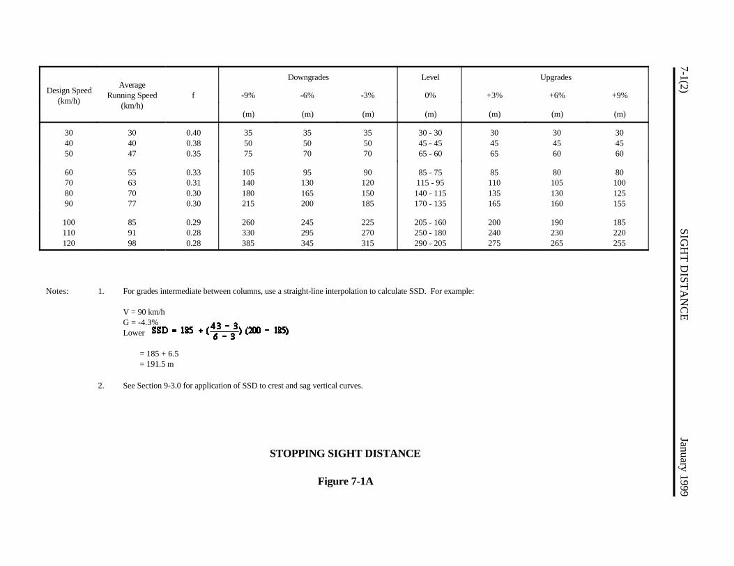
7-1(2)SIG
HT
DIST
AN
CE
January 1999
Design Speed(km/h)
AverageRunning Speed
(km/h)f
Downgrades Level Upgrades
-9% -6% -3% 0% +3% +6% +9%
(m) (m) (m) (m) (m) (m) (m)
304050
304047
0.400.380.35
355075
355070
355070
30 - 3045 - 4565 - 60
304565
304560
304560
60708090
55637077
0.330.310.300.30
105140180215
95130165200
90120150185
85 - 75115 - 95140 - 115170 - 135
85110135165
80105130160
80100125155
100110120
859198
0.290.280.28
260330385
245295345
225270315
205 - 160250 - 180290 - 205
200240275
190230265
185220255
Notes: 1. For grades intermediate between columns, use a straight-line interpolation to calculate SSD. For example:
V = 90 km/hG = -4.3%Lower
= 185 + 6.5= 191.5 m
2. See Section 9-3.0 for application of SSD to crest and sag vertical curves.
STOPPING SIGHT DISTANCE
Figure 7-1A
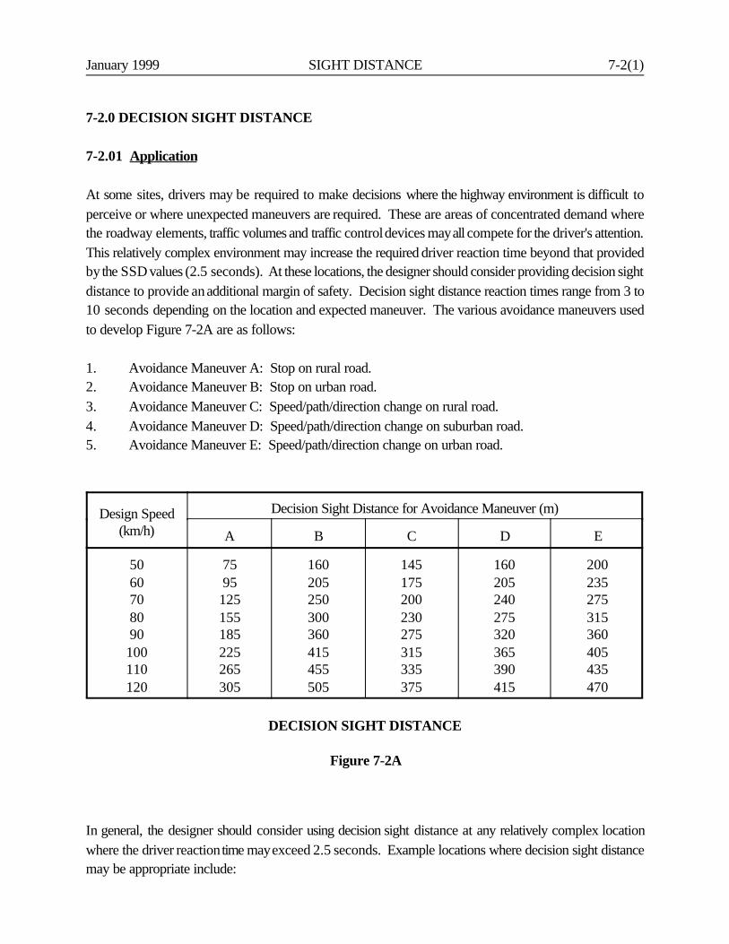
January 1999 SIGHT DISTANCE 7-2(1)
7-2.0 DECISION SIGHT DISTANCE
7-2.01 Application
At some sites, drivers may be required to make decisions where the highway environment is difficult toperceive or where unexpected maneuvers are required. These are areas of concentrated demand wherethe roadway elements, traffic volumes and traffic control devices may all compete for the driver's attention.This relatively complex environment may increase the required driver reaction time beyond that providedby the SSD values (2.5 seconds). At these locations, the designer should consider providing decision sightdistance to provide an additional margin of safety. Decision sight distance reaction times range from 3 to10 seconds depending on the location and expected maneuver. The various avoidance maneuvers usedto develop Figure 7-2A are as follows:
1. Avoidance Maneuver A: Stop on rural road.2. Avoidance Maneuver B: Stop on urban road.3. Avoidance Maneuver C: Speed/path/direction change on rural road.4. Avoidance Maneuver D: Speed/path/direction change on suburban road.5. Avoidance Maneuver E: Speed/path/direction change on urban road.
Design Speed(km/h)
Decision Sight Distance for Avoidance Maneuver (m)
A B C D E
5060708090100110120
7595125155185225265305
160205250300360415455505
145175200230275315335375
160205240275320365390415
200235275315360405435470
DECISION SIGHT DISTANCE
Figure 7-2A
In general, the designer should consider using decision sight distance at any relatively complex locationwhere the driver reaction time may exceed 2.5 seconds. Example locations where decision sight distancemay be appropriate include:

7-2(2) SIGHT DISTANCE January 1999
1. freeway exits;2. freeway lane drops;3. left-side entrances or exits;4. at-grade intersections near a horizontal curve;5. railroad/highway grade crossings;6. detours;7. along high-speed, high-volume urban arterials with considerable roadside friction; or8. traffic signals on high-speed rural highways.
As with SSD, the height of eye is 1070 mm and the height of object is typically 150 mm. However,candidate sites for decision sight distance may also be candidate sites for assuming that the "object" is thepavement surface (e.g., freeway exits). Therefore, the designer should consider a 0.0-mm height of objectfor application at some sites.
7-2.02 Examples* * * * * * * *
Example 7-2.1
Given:
An exit on a suburban freeway under design (design speed = 100 km/h) is located just beyond a bridge.The freeway passes over. The grade on each side of the overpass is 3%. The freeway will carry high trafficvolumes.
Problem: Determine the needed sight distance to the exit gore.
Solution:
A freeway exit is a major decision point for the driver, and the highway design should provide decision sightdistance to the exit gore. The avoidance maneuver is a speed/path/direction change (i.e., AvoidanceManeuver D).
1. From Figure 7-2A, the decision sight distance = 365 m.
2. Calculate the length of the crest vertical curve for the freeway overpass. The algebraic differencein grade change is 6%. A height of object of 0.0 mm to the exit gore will be used. Section 9-3.0provides the following equations for vertical curve lengths:
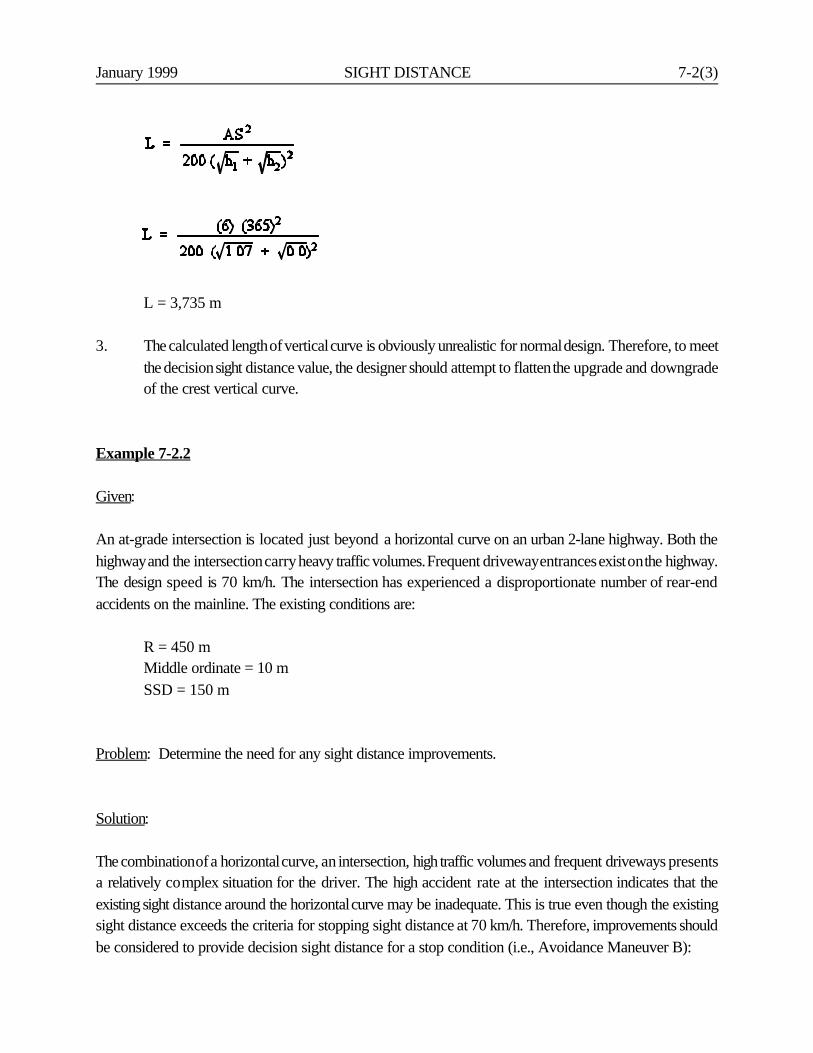
January 1999 SIGHT DISTANCE 7-2(3)
L = 3,735 m
3. The calculated length of vertical curve is obviously unrealistic for normal design. Therefore, to meetthe decision sight distance value, the designer should attempt to flatten the upgrade and downgradeof the crest vertical curve.
Example 7-2.2
Given:
An at-grade intersection is located just beyond a horizontal curve on an urban 2-lane highway. Both thehighway and the intersection carry heavy traffic volumes. Frequent driveway entrances exist on the highway.The design speed is 70 km/h. The intersection has experienced a disproportionate number of rear-endaccidents on the mainline. The existing conditions are:
R = 450 mMiddle ordinate = 10 mSSD = 150 m
Problem: Determine the need for any sight distance improvements.
Solution:
The combination of a horizontal curve, an intersection, high traffic volumes and frequent driveways presentsa relatively complex situation for the driver. The high accident rate at the intersection indicates that theexisting sight distance around the horizontal curve may be inadequate. This is true even though the existingsight distance exceeds the criteria for stopping sight distance at 70 km/h. Therefore, improvements shouldbe considered to provide decision sight distance for a stop condition (i.e., Avoidance Maneuver B):
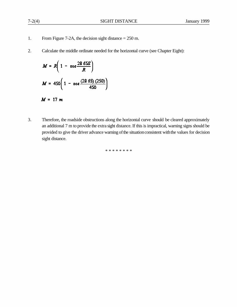
7-2(4) SIGHT DISTANCE January 1999
1. From Figure 7-2A, the decision sight distance = 250 m.
2. Calculate the middle ordinate needed for the horizontal curve (see Chapter Eight):
3. Therefore, the roadside obstructions along the horizontal curve should be cleared approximatelyan additional 7 m to provide the extra sight distance. If this is impractical, warning signs should beprovided to give the driver advance warning of the situation consistent with the values for decisionsight distance.
* * * * * * * *

January 1999 SIGHT DISTANCE 7-3(1)
7-3.0 INTERSECTION SIGHT DISTANCE
Section 11-2.0 discusses the design requirements of sight distance for intersections at-grade.
January 1999 HORIZONTAL ALIGNMENT 8-i
Chapter Eight
HORIZONTAL ALIGNMENT
Table of Contents
Section Page
8-1.0 DEFINITIONS . . . . . . . . . . . . . . . . . . . . . . . . . . . . . . . . . . . . . . . . . . . . . . . . 8-1(1)
8-2.0 RURAL HIGHWAYS/HIGH-SPEED URBAN HIGHWAYS . . . . . . . . . . . 8-2(1)
8-2.01 General Controls . . . . . . . . . . . . . . . . . . . . . . . . . . . . . . . . . . . . . 8-2(1)8-2.02 Horizontal Curvature . . . . . . . . . . . . . . . . . . . . . . . . . . . . . . . . . . 8-2(2)
8-2.02.01 Theoretical Discussion . . . . . . . . . . . . . . . . . . . . 8-2(2)8-2.02.02 Application . . . . . . . . . . . . . . . . . . . . . . . . . . . . . 8-2(2)8-2.02.03 Types of Curvature . . . . . . . . . . . . . . . . . . . . . . . 8-2(3)
8-2.03 Superelevation Development . . . . . . . . . . . . . . . . . . . . . . . . . . . . 8-2(5)
8-2.03.01 Axis of Rotation . . . . . . . . . . . . . . . . . . . . . . . . . 8-2(5)8-2.03.02 Transition Length (Two-Lane Roadways) . . . . . 8-2(8)8-2.03.03 Transition Length (Multilane Highways) . . . . . . 8-2(8)8-2.03.04 Application of Transition Length . . . . . . . . . . . . 8-2(10)8-2.03.05 Effects of Curvature Type . . . . . . . . . . . . . . . . . . 8-2(10)8-2.03.06 Shoulder Superelevation . . . . . . . . . . . . . . . . . . . 8-2(14)8-2.03.07 Typical Figures . . . . . . . . . . . . . . . . . . . . . . . . . . 8-2(14)
8-2.04 Horizontal Sight Distance . . . . . . . . . . . . . . . . . . . . . . . . . . . . . . 8-2(20)
8-2.04.01 Sight Obstruction (Definition) . . . . . . . . . . . . . . 8-2(20)8-2.04.02 Length of Curve > Sight Distance . . . . . . . . . . . 8-2(20)8-2.04.03 Length of Curve < Sight Distance . . . . . . . . . . . 8-2(25)8-2.04.04 Application . . . . . . . . . . . . . . . . . . . . . . . . . . . . . 8-2(25)8-2.04.05 Longitudinal Barriers . . . . . . . . . . . . . . . . . . . . . 8-2(27)
8-2.05 Crossover Line . . . . . . . . . . . . . . . . . . . . . . . . . . . . . . . . . . . . . . . 8-2(27)
8-3.0 LOW-SPEED URBAN STREETS . . . . . . . . . . . . . . . . . . . . . . . . . . . . . . . . . 8-3(1)
8-3.01 General Controls . . . . . . . . . . . . . . . . . . . . . . . . . . . . . . . . . . . . . 8-3(1)8-3.02 Horizontal Curvature . . . . . . . . . . . . . . . . . . . . . . . . . . . . . . . . . . 8-3(1)
8-ii HORIZONTAL ALIGNMENT January 1999
Table of Contents(Continued)
Page
8-3.02.01 Theoretical Discussion . . . . . . . . . . . . . . . . . . . . 8-3(1)8-3.02.02 Application . . . . . . . . . . . . . . . . . . . . . . . . . . . . . 8-3(1)8-3.02.03 Types of Curvature . . . . . . . . . . . . . . . . . . . . . . . 8-3(5)
8-3.03 Superelevation Development . . . . . . . . . . . . . . . . . . . . . . . . . . . 8-3(5)8-3.04 Horizontal Sight Distance . . . . . . . . . . . . . . . . . . . . . . . . . . . . . 8-3(5)
January 1999 HORIZONTAL ALIGNMENT 8-1(1)
Chapter Eight
HORIZONTAL ALIGNMENT
8-1.0 DEFINITIONS
1. Simple Curves. These are continuous arcs of constant radius which achieve the necessary highwaydeflection without an entering or exiting transition.
2. Compound Curves. These are a series of two or more simple curves with deflections in the samedirection immediately adjacent to each other.
3. Reverse Curves. These are two simple curves with deflections in opposite directions which arejoined by a relatively short tangent distance.
4. Broken-Back Curves. These are closely spaced horizontal curves with deflection angles in the samedirection with an intervening, short tangent section.
5. Spiral Curves. A curve of continuously varying radius.
6. Superelevation (e). Superelevation is the amount of cross slope or "bank" provided on a horizontalcurve to counterbalance, in combination with side friction, the centrifugal force of a vehicletraversing the curve.
7. Maximum Superelevation (emax). The maximum rate of superelevation (emax) is an overallsuperelevation control used on a specific facility. Its selection depends on several factors includingclimatic conditions, terrain conditions, type of area (rural or urban) and highway functionalclassification.
8. Side Friction (f). The interaction between the tire and the pavement surface to counterbalance, incombination with the superelevation, the centrifugal force of a vehicle traversing a horizontal curve.
9. Maximum Side Friction (fmax). Limiting values selected by AASHTO for use in the design ofhorizontal curves. The designated fmax values represent a threshold of driver discomfort and not thepoint of impending skid.
10. Superelevation Transition Length. The superelevation transition length is the distance required totransition the roadway from a normal crown section to full superelevation.
8-1(2) HORIZONTAL ALIGNMENT January 1999
The superelevation transition length is the sum of the tangent runout (TR) and superelevationrunoff (L) distances:
a. Tangent Runout (TR). Tangent runout is the distance needed to change from a normalcrown section to a point where the adverse cross slope of the outside lane or lanes isremoved (i.e., the outside lane(s) is level).
b. Superelevation Runoff (L). Superelevation runoff is the distance needed to change thecross slope from the end of the tangent runout (adverse cross slope removed) to asection that is sloped at the design superelevation rate.
11. Axis of Rotation. The superelevation axis of rotation is the line about which the pavement isrevolved to superelevate the roadway. This line will maintain the normal highway profilethroughout the curve. The axis of rotation is generally located at the point of application ofgrade.
12. Crossover Line. The lane line between any two adjacent lanes of traffic.
13. Superelevation Rollover. Superelevation rollover is the algebraic difference (A) between thesuperelevated travel lane slope and shoulder slope on the outside of a horizontal curve.
14. Normal Crown (NC). The typical cross section on a tangent section of roadway (i.e., nosuperelevation).
15. Remove Adverse Crown (RC). A superelevated roadway section which is sloped across theentire traveled way in the same direction and at a rate equal to the cross slope on the tangentsection.
16. Relative Longitudinal Slope. In superelevation transition sections on two-lane facilities, therelative gradient between the profile grade and edge of traveled way.
17. Open Roadways. All urban facilities with a design speed greater than 70 km/h and all ruralfacilities for all design speeds.
18. Low-Speed Urban Streets. All streets within an urbanized or small urban area with a designspeed of 70 km/h or less.
19. Point of Application of Grade. The point on the cross section where the elevation of thecalculated profile grade list is located.
January 1999 HORIZONTAL ALIGNMENT 8-2(1)
8-2.0 RURAL HIGHWAYS/HIGH-SPEED URBAN HIGHWAYS
This section presents horizontal alignment criteria for all rural highways and for high-speed urbanhighways (V A 80 km/h). See Section 8-3.0 for horizontal alignment criteria for low-speed urbanstreets (V @ 70 km/h).
8-2.01 General Controls
Much of the criteria for horizontal alignment seeks to establish minimum design values which arebased on specific limiting factors. These include side-friction factors, superelevation, longitudinalgradients for superelevation transition, and middle ordinate values for sight distance. In addition, thedesigner should adhere to several general controls for horizontal alignment. These are based onaesthetic and safety considerations. They include:
1. Horizontal alignment should be as directional as possible. Where feasible, minimum radiishould be avoided. Flatter curvature with shorter tangents is generally preferable to sharpcurves connected by long tangents.
2. Curves with small deflection angles should be long enough to avoid the appearance of a kink.For a central angle of 5o or less, the curve should be at least 150-m long. On freeways, thedesigner should try to provide a curve length, in meters, of at least 6 times the design speedin km/h. On other major highways, try to provide a curve length 3 times the design speed.
3. Very small deflection angles may not require a horizontal curve; i.e., the roadway may bedesigned with an angular break. As a general guide, the designer may consider using an anglepoint when the deflection angle is less than 1o. The evaluation on the use of an angle pointwill be based on urban/rural location, aesthetics, construction costs and the visibility of thekink.
4. Broken back curvature should be avoided.
5. Sharp horizontal curves should not be introduced near crest or sag vertical curves. Thecombination of horizontal and vertical curves can greatly reduce sight distance, and thelikelihood of accidents is increased.
6. Horizontal curves and superelevation transitions should be avoided on bridges. These causedesign, construction and operational problems when snow and ice are present. The designershould not, however, avoid placing a curve on a bridge if this results in sharp horizontalcurves on the approaching roadway. Where a curve is necessary on a bridge, a simple curve
8-2(2) HORIZONTAL ALIGNMENT January 1999
should be used on the bridge, and any superelevation development should be placed on theapproaching roadway.
7. Normally, simple circular curves will be used in design. However, spiral curves may beconsidered throughout the length of a curve to fit the roadway into a restricted roadside.Spiral transition curves should be considered in areas where high speeds are anticipated incombination with tight curvature. For additional information, refer to any available surveymanual.
8. The crossover line will often be a control for setting the rates of superelevation and radiusand profile where two roadways converge. Freeway gores are an example.
9. The radius of a ramp curve ending parallel to a freeway should be within 300 meters of theradius of the freeway.
8-2.02 Horizontal Curvature
8-2.02.01 Theoretical Discussion
From the laws of mechanics, the point mass formula for vehicular operation on a curve is used todefine the curvature radius. The basic equation is:
where: R = radius of curve, me = superelevation rate (expressed as a decimal)f = side-friction factorV = vehicle speed, km/h
A number of assumptions are reflected in the values used in highway design for rural highways andhigh-speed urban highways. These apply both to the limiting values for curvature and to the methodof determining superelevation for radii greater than the minimum. The designer should reference APolicy on Geometric Design of Highways and Streets for more information.
8-2.02.02 Application
Figure 8-2A provides design superelevation rates for combinations of radii and design speeds. Thefigure also provides the design lengths for superelevation runoff (from the end of the tangent runout
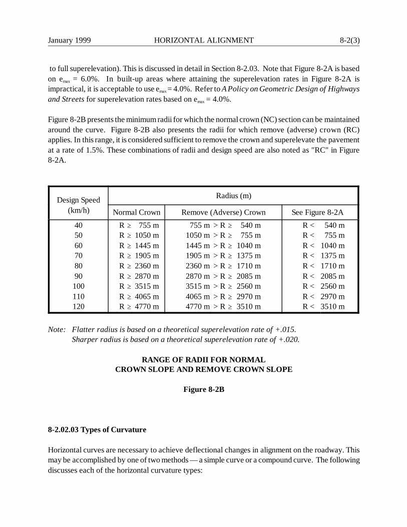
January 1999 HORIZONTAL ALIGNMENT 8-2(3)
to full superelevation). This is discussed in detail in Section 8-2.03. Note that Figure 8-2A is basedon emax = 6.0%. In built-up areas where attaining the superelevation rates in Figure 8-2A isimpractical, it is acceptable to use emax = 4.0%. Refer to A Policy on Geometric Design of Highwaysand Streets for superelevation rates based on emax = 4.0%.
Figure 8-2B presents the minimum radii for which the normal crown (NC) section can be maintainedaround the curve. Figure 8-2B also presents the radii for which remove (adverse) crown (RC)applies. In this range, it is considered sufficient to remove the crown and superelevate the pavementat a rate of 1.5%. These combinations of radii and design speed are also noted as "RC" in Figure8-2A.
Design Speed(km/h)
Radius (m)
Normal Crown Remove (Adverse) Crown See Figure 8-2A405060708090100110120
R AR AR AR AR AR AR AR AR A
755 m1050 m1445 m1905 m2360 m2870 m3515 m4065 m4770 m
755 m1050 m1445 m1905 m2360 m2870 m3515 m4065 m4770 m
> R A> R A> R A> R A> R A> R A> R A> R A> R A
540 m 755 m1040 m1375 m1710 m2085 m2560 m2970 m3510 m
R <R <R <R <R <R <R <R <R <
540 m 755 m1040 m1375 m1710 m2085 m2560 m2970 m3510 m
Note: Flatter radius is based on a theoretical superelevation rate of +.015.Sharper radius is based on a theoretical superelevation rate of +.020.
RANGE OF RADII FOR NORMALCROWN SLOPE AND REMOVE CROWN SLOPE
Figure 8-2B
8-2.02.03 Types of Curvature
Horizontal curves are necessary to achieve deflectional changes in alignment on the roadway. Thismay be accomplished by one of two methods — a simple curve or a compound curve. The followingdiscusses each of the horizontal curvature types:
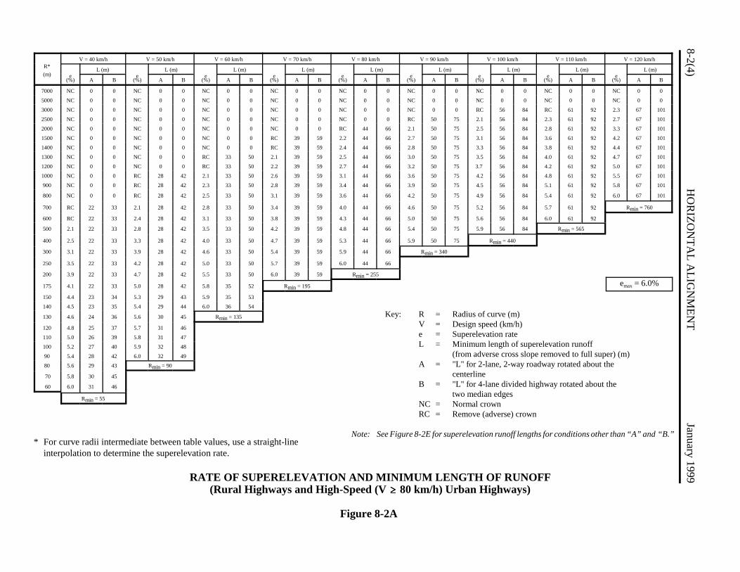
* For curve radii intermediate between table values, use a straight-lineinterpolation to determine the superelevation rate.
8-2(4)H
OR
IZON
TAL A
LIGN
MEN
TJanuary 1999
emax = 6.0%
Key: R = Radius of curve (m)V = Design speed (km/h)e = Superelevation rateL = Minimum length of superelevation runoff
(from adverse cross slope removed to full super) (m)A = "L" for 2-lane, 2-way roadway rotated about the
centerlineB = "L" for 4-lane divided highway rotated about the
two median edges NC = Normal crownRC = Remove (adverse) crown
Note: See Figure 8-2E for superelevation runoff lengths for conditions other than “A” and “B.”
R*(m)
V = 40 km/h V = 50 km/h V = 60 km/h V = 70 km/h V = 80 km/h V = 90 km/h V = 100 km/h V = 110 km/h V = 120 km/h
e(%)
L (m)e
(%)
L (m)e
(%)
L (m)e
(%)
L (m)e
(%)
L (m)e
(%)
L (m)e
(%)
L (m)e
(%)
L (m)e
(%)
L (m)
A B A B A B A B A B A B A B A B A B
7000 NC 0 0 NC 0 0 NC 0 0 NC 0 0 NC 0 0 NC 0 0 NC 0 0 NC 0 0 NC 0 0
5000 NC 0 0 NC 0 0 NC 0 0 NC 0 0 NC 0 0 NC 0 0 NC 0 0 NC 0 0 NC 0 0
3000 NC 0 0 NC 0 0 NC 0 0 NC 0 0 NC 0 0 NC 0 0 RC 56 84 RC 61 92 2.3 67 101
2500 NC 0 0 NC 0 0 NC 0 0 NC 0 0 NC 0 0 RC 50 75 2.1 56 84 2.3 61 92 2.7 67 101
2000 NC 0 0 NC 0 0 NC 0 0 NC 0 0 RC 44 66 2.1 50 75 2.5 56 84 2.8 61 92 3.3 67 101
1500 NC 0 0 NC 0 0 NC 0 0 RC 39 59 2.2 44 66 2.7 50 75 3.1 56 84 3.6 61 92 4.2 67 101
1400 NC 0 0 NC 0 0 NC 0 0 RC 39 59 2.4 44 66 2.8 50 75 3.3 56 84 3.8 61 92 4.4 67 101
1300 NC 0 0 NC 0 0 RC 33 50 2.1 39 59 2.5 44 66 3.0 50 75 3.5 56 84 4.0 61 92 4.7 67 101
1200 NC 0 0 NC 0 0 RC 33 50 2.2 39 59 2.7 44 66 3.2 50 75 3.7 56 84 4.2 61 92 5.0 67 101
1000 NC 0 0 RC 28 42 2.1 33 50 2.6 39 59 3.1 44 66 3.6 50 75 4.2 56 84 4.8 61 92 5.5 67 101
900 NC 0 0 RC 28 42 2.3 33 50 2.8 39 59 3.4 44 66 3.9 50 75 4.5 56 84 5.1 61 92 5.8 67 101
800 NC 0 0 RC 28 42 2.5 33 50 3.1 39 59 3.6 44 66 4.2 50 75 4.9 56 84 5.4 61 92 6.0 67 101
700 RC 22 33 2.1 28 42 2.8 33 50 3.4 39 59 4.0 44 66 4.6 50 75 5.2 56 84 5.7 61 92 Rmin = 760
600 RC 22 33 2.4 28 42 3.1 33 50 3.8 39 59 4.3 44 66 5.0 50 75 5.6 56 84 6.0 61 92
500 2.1 22 33 2.8 28 42 3.5 33 50 4.2 39 59 4.8 44 66 5.4 50 75 5.9 56 84 Rmin = 565
400 2.5 22 33 3.3 28 42 4.0 33 50 4.7 39 59 5.3 44 66 5.9 50 75 Rmin = 440
300 3.1 22 33 3.9 28 42 4.6 33 50 5.4 39 59 5.9 44 66 Rmin = 340
250 3.5 22 33 4.2 28 42 5.0 33 50 5.7 39 59 6.0 44 66
200 3.9 22 33 4.7 28 42 5.5 33 50 6.0 39 59 Rmin = 255
175 4.1 22 33 5.0 28 42 5.8 35 52 Rmin = 195
150 4.4 23 34 5.3 29 43 5.9 35 53
140 4.5 23 35 5.4 29 44 6.0 36 54
130 4.6 24 36 5.6 30 45 Rmin = 135
120 4.8 25 37 5.7 31 46
110 5.0 26 39 5.8 31 47
100 5.2 27 40 5.9 32 48
90 5.4 28 42 6.0 32 49
80 5.6 29 43 Rmin = 90
70 5.8 30 45
60 6.0 31 46
Rmin = 55
RATE OF SUPERELEVATION AND MINIMUM LENGTH OF RUNOFF(Rural Highways and High-Speed (V AAAA 80 km/h) Urban Highways)
Figure 8-2A
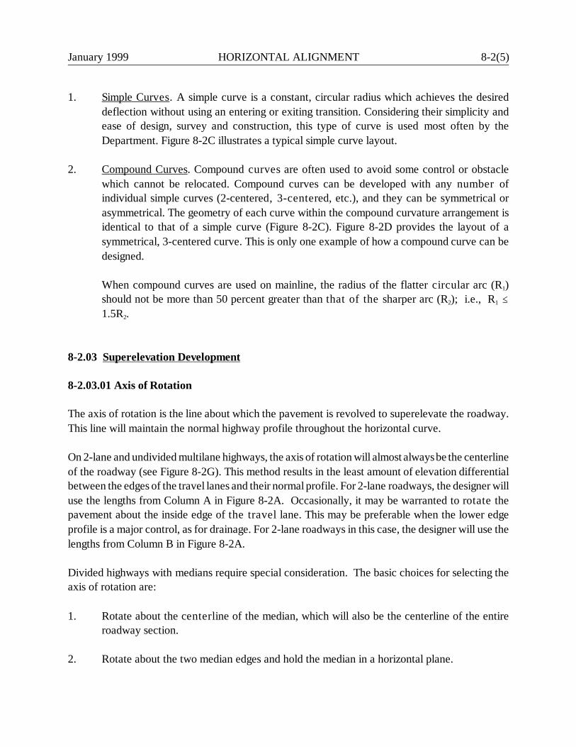
January 1999 HORIZONTAL ALIGNMENT 8-2(5)
1. Simple Curves. A simple curve is a constant, circular radius which achieves the desireddeflection without using an entering or exiting transition. Considering their simplicity andease of design, survey and construction, this type of curve is used most often by theDepartment. Figure 8-2C illustrates a typical simple curve layout.
2. Compound Curves. Compound curves are often used to avoid some control or obstaclewhich cannot be relocated. Compound curves can be developed with any number ofindividual simple curves (2-centered, 3-centered, etc.), and they can be symmetrical orasymmetrical. The geometry of each curve within the compound curvature arrangement isidentical to that of a simple curve (Figure 8-2C). Figure 8-2D provides the layout of asymmetrical, 3-centered curve. This is only one example of how a compound curve can bedesigned.
When compound curves are used on mainline, the radius of the flatter circular arc (R1)should not be more than 50 percent greater than that of the sharper arc (R2); i.e., R1 @1.5R2.
8-2.03 Superelevation Development
8-2.03.01 Axis of Rotation
The axis of rotation is the line about which the pavement is revolved to superelevate the roadway.This line will maintain the normal highway profile throughout the horizontal curve.
On 2-lane and undivided multilane highways, the axis of rotation will almost always be the centerlineof the roadway (see Figure 8-2G). This method results in the least amount of elevation differentialbetween the edges of the travel lanes and their normal profile. For 2-lane roadways, the designer willuse the lengths from Column A in Figure 8-2A. Occasionally, it may be warranted to rotate thepavement about the inside edge of the travel lane. This may be preferable when the lower edgeprofile is a major control, as for drainage. For 2-lane roadways in this case, the designer will use thelengths from Column B in Figure 8-2A.
Divided highways with medians require special consideration. The basic choices for selecting theaxis of rotation are:
1. Rotate about the centerline of the median, which will also be the centerline of the entireroadway section.
2. Rotate about the two median edges and hold the median in a horizontal plane.

8-2(6) HORIZONTAL ALIGNMENT January 1999
CURVE SYMBOLS
F = Deflection Angle, degreesT = Tangent Distance = distance from PC to PI =
distance from PI to PTL = Length of curve in meters = distance from PC to PT
along curveR = Radius of curveE = External Distance (PI to mid-point of curve)LC = Length of long chord — PC to PTM = Middle Ordinate (mid-point of arc to mid-point of
long chord)
CIRCULAR CURVE ABBREVIATIONS
P.C.= PC = Point of Curvature (Beginning of Curve)P.T. = PT = Point of Tangency (End of Curve)P.I. = PI = Point of Intersection of TangentsP.C.C. = PCC = Point of Compound Curvature
CURVE FORMULA
LAYOUT OF SIMPLE CURVE
Figure 8-2C

Equations for Any Two-Centered Compound Curves:
I = Total Deflection Angle = ∆1 + ∆2X = R2 sin I + (R1 - R2) sin ∆1Y = R1 - R2 cos I - (R1 - R2) cos ∆1Tb =
Isin Y
Ta = X - Tb cos I
Equations for Any Three-Centered Compound Curves:
I = Total Deflection Angle = ∆1 + ∆2 + ∆3X = (R1 - R2) sin ∆1 + (R2 - R3) sin (∆1 + ∆2) + R3 sin IY = R1 - R3 cos I - (R1 - R2) cos ∆1 - (R2 - R3) cos (∆1 + ∆2)Tb =
Isin Y
Ta = X - Tb cos I
Equations for Symmetrical Three-Centered Compound Curve (R1 = R3; ∆1 =∆3, as shown in Figure):I = Total Deflection Angle = 2 ∆1 + ∆2X = (R1 - R2) sin ∆1 + (R2 - R1) sin (∆1 + ∆2) + R1 sin IY = R1 - R2 cos I - (R1 - R2) cos ∆1 - (R2 - R1) cos (∆1 + ∆2)Tb =
Isin Y
Ta = X - Tb cos I
Note: R1 � 1.5 R2
Note: This is only one example of how acompound curve can be designed.
SYMMETRICAL THREE-CENTERED COMPOUND CURVEFigure 8-2
January 1999H
OR
IZON
TAL A
LIGN
MEN
T 8-2(7)
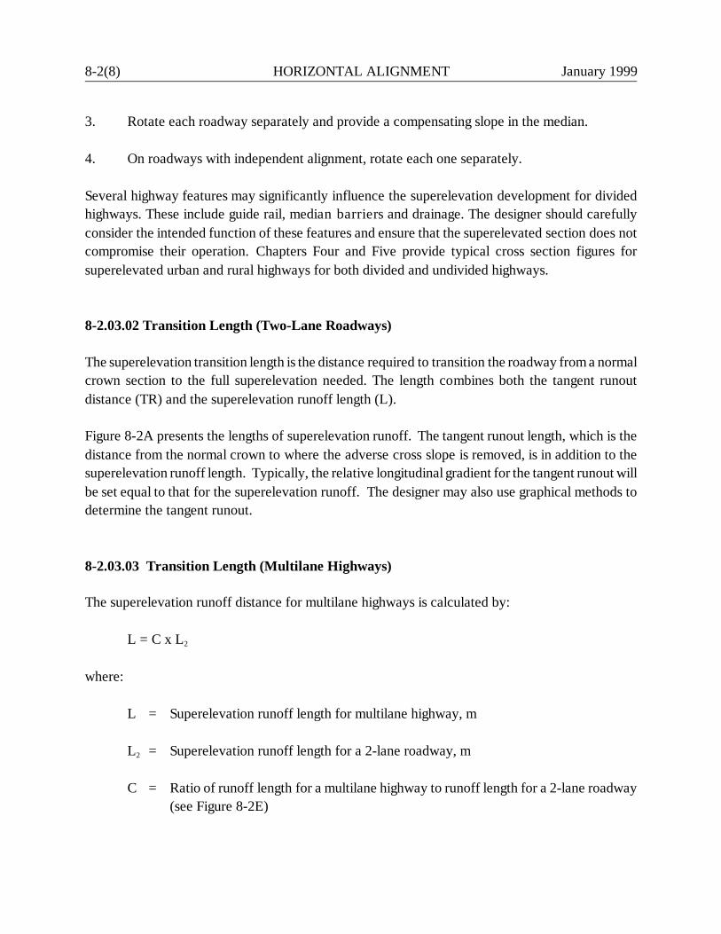
8-2(8) HORIZONTAL ALIGNMENT January 1999
3. Rotate each roadway separately and provide a compensating slope in the median.
4. On roadways with independent alignment, rotate each one separately.
Several highway features may significantly influence the superelevation development for dividedhighways. These include guide rail, median barriers and drainage. The designer should carefullyconsider the intended function of these features and ensure that the superelevated section does notcompromise their operation. Chapters Four and Five provide typical cross section figures forsuperelevated urban and rural highways for both divided and undivided highways.
8-2.03.02 Transition Length (Two-Lane Roadways)
The superelevation transition length is the distance required to transition the roadway from a normalcrown section to the full superelevation needed. The length combines both the tangent runoutdistance (TR) and the superelevation runoff length (L).
Figure 8-2A presents the lengths of superelevation runoff. The tangent runout length, which is thedistance from the normal crown to where the adverse cross slope is removed, is in addition to thesuperelevation runoff length. Typically, the relative longitudinal gradient for the tangent runout willbe set equal to that for the superelevation runoff. The designer may also use graphical methods todetermine the tangent runout.
8-2.03.03 Transition Length (Multilane Highways)
The superelevation runoff distance for multilane highways is calculated by:
L = C x L2
where:
L = Superelevation runoff length for multilane highway, m
L2 = Superelevation runoff length for a 2-lane roadway, m
C = Ratio of runoff length for a multilane highway to runoff length for a 2-lane roadway(see Figure 8-2E)

January 1999 HORIZONTAL ALIGNMENT 8-2(9)
Number of LanesBeing Rotated* C
One
Two
Three
Four
1.0
1.5**
2.0
2.5
* This column refers to the number of lanes being rotated on either side of the axis rotation.Select the higher value. For example, if the axis of rotation for a 3-lane roadway is about theedge of the interior lane, two lanes will be rotated on one side of the axis and one lane will berotated on the other side. The higher number is two, and C is 1.5.
Note also that a C = 1.5 should be used to determine the superelevation runoff length for a 2-lane, 2-way roadway where the axis of rotation is about either edge of the travelway.
As another example, consider a 5-lane roadway (i.e., four through lanes and a two-way, left-turn lane (TWLTL)) with the axis of rotation in the center of the TWLTL. In this case, thenumber of lanes being rotated is 2.5; therefore, C = 1.75.
** Column B in Figure 8-2A presents values based on C = 1.5.
C VALUES(Superelevation Runoff Lengths, Multilane Highways)
Figure 8-2E

8-2(10) HORIZONTAL ALIGNMENT January 1999
8-2.03.04 Application of Transition Length
The location of the transition length may be shifted within the indicated limits to obtain practicalbeginning and ending points. In most cases, the designer will likely locate the transition termini atthe nearest 20-m or 40-m station. In addition, the designer should examine the relationship betweenthe horizontal and vertical alignment to provide a desirable visual impact.
8-2.03.05 Effects of Curvature Type
Horizontal curvature may be a simple curve or a compound curve. Superelevation development willvary for each type. In addition, superelevation development must be carefully addressed at closelyspaced reverse curves. Each is discussed:
1. Simple Curves. The typical figures in Section 8-2.03.07 illustrate superelevation develop-ment for simple curves. The designer must distribute the placement of the transition lengthbetween the tangent section (where no superelevation is needed) and the curve section(where full superelevation is needed). No distribution method can be completely justified.As an approximation, 60% - 80% of the full superelevation should be reached at the PC. Ifpractical, try to provide 0.67e at the PC. This superelevation rate will be reached at 0.67 ofthe superelevation runoff length.
2. Compound Curvature. The typical figure in Section 8-2.03.07 illustrates the superelevationdevelopment for compound curvature. These criteria should be met:
a. If the distance between the PC and PCC or between two PCC points is less than orequal to 90 m, a uniform longitudinal gradient should be used throughout thetransition.
b. If the distance between the PC and PCC or between two PCC points is more than90 m, it may be preferable to consider the two curves separately. Superelevation forthe entering curve would be developed by the distribution method used for simplecurves. This superelevation rate (ef) would be maintained until it is necessary todevelop the remaining superelevation of the sharper curve.
c. The minimum superelevation runoff length in Figure 8-2A applies to the superele-vation development for the sharpest or controlling curve; i.e., this length is used fromthe end of the tangent runout to the PCC of the controlling curve.
d. Superelevation should be developed so that, for the first and last curve, two-thirdsof the design superelevation rate for those curves will be attained at the PC or PT.
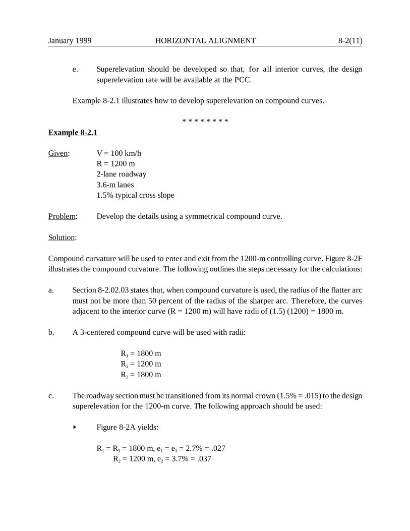
January 1999 HORIZONTAL ALIGNMENT 8-2(11)
e. Superelevation should be developed so that, for all interior curves, the designsuperelevation rate will be available at the PCC.
Example 8-2.1 illustrates how to develop superelevation on compound curves.
* * * * * * * *Example 8-2.1
Given: V = 100 km/hR = 1200 m2-lane roadway3.6-m lanes1.5% typical cross slope
Problem: Develop the details using a symmetrical compound curve.
Solution:
Compound curvature will be used to enter and exit from the 1200-m controlling curve. Figure 8-2Fillustrates the compound curvature. The following outlines the steps necessary for the calculations:
a. Section 8-2.02.03 states that, when compound curvature is used, the radius of the flatter arcmust not be more than 50 percent of the radius of the sharper arc. Therefore, the curvesadjacent to the interior curve (R = 1200 m) will have radii of (1.5) (1200) = 1800 m.
b. A 3-centered compound curve will be used with radii:
R1 = 1800 mR2 = 1200 mR3 = 1800 m
c. The roadway section must be transitioned from its normal crown (1.5% = .015) to the designsuperelevation for the 1200-m curve. The following approach should be used:
Y Figure 8-2A yields:
R1 = R3 = 1800 m, e1 = e3 = 2.7% = .027R2 = 1200 m, e2 = 3.7% = .037
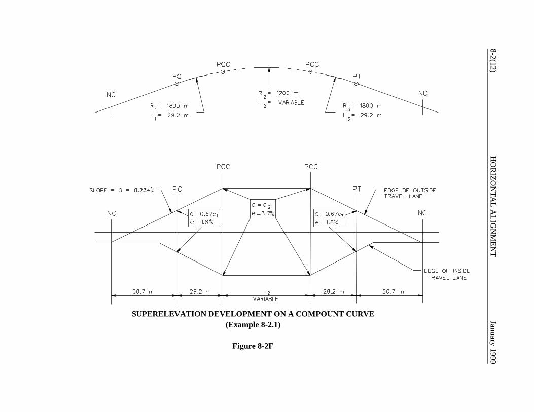
8-2(12)H
OR
IZON
TAL A
LIGN
MEN
TJanuary 1999
SUPERELEVATION DEVELOPMENT ON A COMPOUNT CURVE(Example 8-2.1)
Figure 8-2F
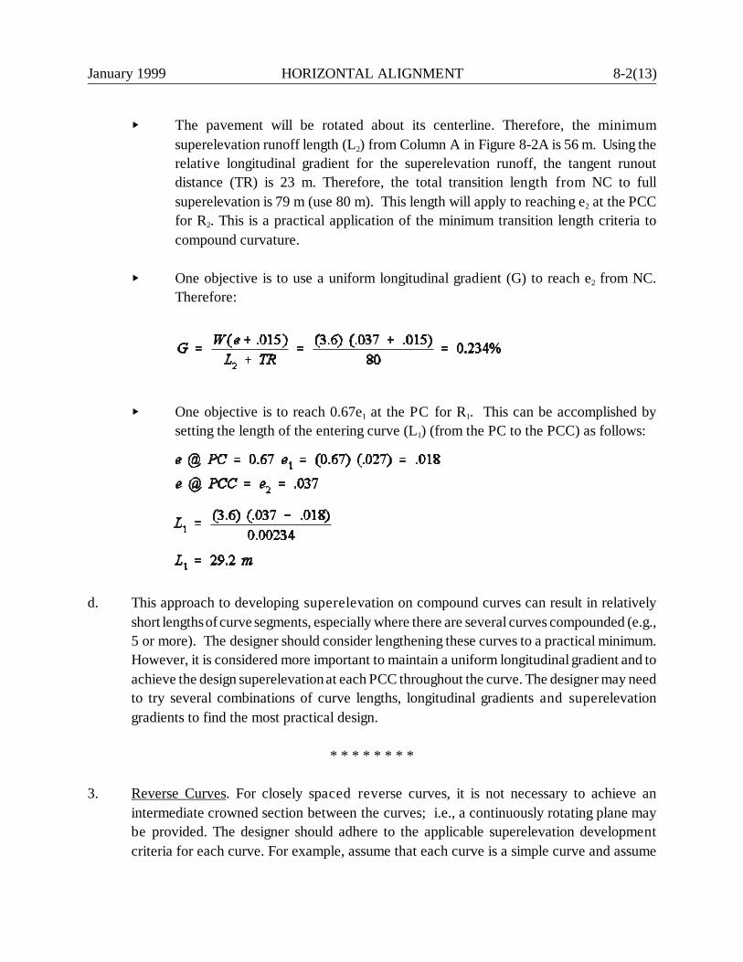
January 1999 HORIZONTAL ALIGNMENT 8-2(13)
Y The pavement will be rotated about its centerline. Therefore, the minimumsuperelevation runoff length (L2) from Column A in Figure 8-2A is 56 m. Using therelative longitudinal gradient for the superelevation runoff, the tangent runoutdistance (TR) is 23 m. Therefore, the total transition length from NC to fullsuperelevation is 79 m (use 80 m). This length will apply to reaching e2 at the PCCfor R2. This is a practical application of the minimum transition length criteria tocompound curvature.
Y One objective is to use a uniform longitudinal gradient (G) to reach e2 from NC.Therefore:
Y One objective is to reach 0.67e1 at the PC for R1. This can be accomplished bysetting the length of the entering curve (L1) (from the PC to the PCC) as follows:
d. This approach to developing superelevation on compound curves can result in relativelyshort lengths of curve segments, especially where there are several curves compounded (e.g.,5 or more). The designer should consider lengthening these curves to a practical minimum.However, it is considered more important to maintain a uniform longitudinal gradient and toachieve the design superelevation at each PCC throughout the curve. The designer may needto try several combinations of curve lengths, longitudinal gradients and superelevationgradients to find the most practical design.
* * * * * * * *
3. Reverse Curves. For closely spaced reverse curves, it is not necessary to achieve anintermediate crowned section between the curves; i.e., a continuously rotating plane maybe provided. The designer should adhere to the applicable superelevation developmentcriteria for each curve. For example, assume that each curve is a simple curve and assume
8-2(14) HORIZONTAL ALIGNMENT January 1999
that 0.67 of the full superelevation is provided at the PT and PC. This means that theminimum length of the tangent section between the PT and PC is:
where:
Ltan = Tangent distance between PT and PC, mL1 = Superelevation runoff length for first curve, mTR1 = Tangent runout length for first curve, mTR2 = Tangent runout length for second curve, mL2 = Superelevation runoff length for second curve, m
It is undesirable to have a zero tangent distance between the two curves (i.e., where the PT ofthe first curve is coincident with the PC of the second curve). This type of alignment requiresthe driver to shift his steering from a curve in one direction to a curve in the other at exactly thepoint of reverse curvature if he is to remain within his lane. It is not possible to have aminimum amount of superelevation at the beginning of the curve, and transitions are moredifficult. This lowers the effective design speed of the curve within the transition zone. It ispreferable to use tighter radii to provide the tangent length required to effect the introductionof superelevation and allow the driver time to react. In general, even under restrictedconditions, 2.5 seconds of travel time should be provided on a tangent section.
8-2.03.06 Shoulder Superelevation
Figures 4H and 5J provide the detail for shoulder superelevation on the high side of the roadway. Thisdetail will apply when the shoulder width is 1.2 m or more and will apply to the entire range ofsuperelevation rates (1.5% to 6.0%). When the shoulder width is less than 1.2 m, it will be superelevatedat the same rate and in the same direction as the travel lane. In this case, the designer should ensure thatthe drainage for the area beyond the roadway will not flow into the roadway.
On the low side, the shoulder cross slope will remain equal to its rate on the tangent section until thesuperelevated rate exceeds that value. Then, the shoulder will be sloped at the same rate as thesuperelevated travel lanes.
Section 10-1.02.02 contains criteria on shoulders across superelevated bridges.
8-2.03.07 Typical Figures
January 1999 HORIZONTAL ALIGNMENT 8-2(15)
Based on the discussion in the previous sections, the following figures illustrate the Department'smethods for superelevation development:
1. Figure 8-2G is applicable to 2-lane roadways rotated about the centerline where a simplecurve is used.
2. Figure 8-2H is applicable to 2-lane roadways rotated about the centerline where compoundcurvature is provided.
3. Figure 8-2I is applicable to roadways with three or four lanes where a simple curve is used.The axis of rotation is about the centerline (4-lane roadways) or about one inside edge oftravel lane (3-lane roadways). If a compound curve is used, the designer will modify thesuperelevation development as illustrated in Figure 8-2H.
4. Figure 8-2J is applicable to roadways with five or six lanes where a simple curve is used. Theaxis of rotation is about the centerline (6-lane roadway) or about either edge of the centerlane (5-lane roadways). If a compound curve is used, the designer will modify thesuperelevation development as illustrated in Figure 8-2H.
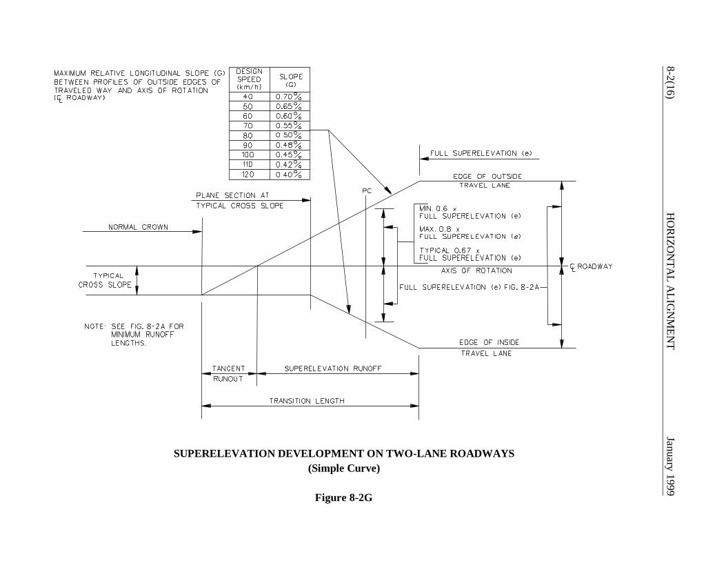
8-2(16)H
OR
IZON
TAL A
LIGN
MEN
TJanuary 1999
SUPERELEVATION DEVELOPMENT ON TWO-LANE ROADWAYS(Simple Curve)
Figure 8-2G
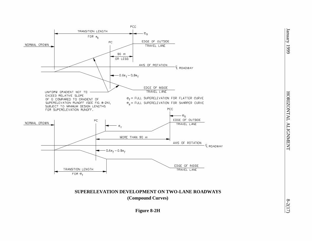
January 1999 H
OR
IZON
TAL A
LIGN
MEN
T8-2(17)
SUPERELEVATION DEVELOPMENT ON TWO-LANE ROADWAYS(Compound Curves)
Figure 8-2H

8-2(18)H
OR
IZON
TAL A
LIGN
MEN
TJanuary 1999
SUPERELEVATION DEVELOPMENT ON THREE-LANE AND FOUR-LANE ROADWAYS(Simple Curve)
Figure 8-2I
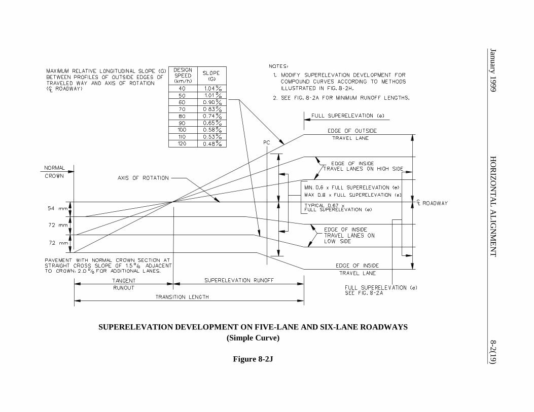
January 1999 H
OR
IZON
TAL A
LIGN
MEN
T8-2(19)
SUPERELEVATION DEVELOPMENT ON FIVE-LANE AND SIX-LANE ROADWAYS(Simple Curve)
Figure 8-2J

8-2(20) HORIZONTAL ALIGNMENT January 1999
(Equation 8-2.1)
8-2.04 Horizontal Sight Distance
The designer must evaluate the impact of sight obstructions which are located laterally on the insideof horizontal curves. These may interfere with the required sight distance and should be removed ifpractical.
8-2.04.01 Sight Obstruction (Definition)
Sight obstructions on the inside of a horizontal curve are defined as obstacles of considerable lengthwhich interfere with the line of sight on a continuous basis. These include walls, cut slopes, woodedareas, buildings and high farm crops. In general, point obstacles such as traffic signs and utility polesare not considered sight obstructions on the inside of horizontal curves. The designer must examineeach curve individually to determine whether it is necessary to remove an obstruction or adjust thehorizontal alignment to obtain the required sight distance.
8-2.04.02 Length of Curve > Sight Distance
Where the length of curve (L) is greater than the sight distance (S) used for design, the neededclearance on the inside of the horizontal curve is calculated as follows:
Where:
M = Middle ordinate, or distance from the center of the inside travel lane to theobstruction, m
R = Radius of centerline of inside travel lane, m
S = Sight distance, m
Note: The expression is in degrees, not radians.
Stopping Sight Distance (SSD)
At a minimum, SSD will be available throughout the horizontal curve. Figure 8-2K and Figure 8-2Lprovide the horizontal clearance criteria (i.e, middle ordinate) for various combinations of stopping

January 1999 HORIZONTAL ALIGNMENT 8-2(21)
sight distance and curve radii. For those selections of S which fall outside of the figures (e.g., M >16 m and/or R < 50 m), the designer should use Equation 8-2.1 to calculate the needed clearance.
The Example on Figure 8-2M illustrates the determination of clearance requirements at a horizontal curvebased on SSD.
Decision Sight Distance (DSD)
At some locations, it may be warranted to provide decision sight distance at the horizontal curve.Chapter Seven discusses candidate sites and provides design values for these sight distance criteria.These "S" values should be used in the basic equation to calculate "M" (Equation 8-2.1).
Entering/Exiting Portions
The M values from Figures 8-2K and 8-2L apply between the PC and PT. In addition, sometransition is needed on the entering and exiting portions of the curve. The designer should use thefollowing steps:
Step 1: Locate the point which is on the outside edge of shoulder and a distance of S/2 before thePC.
Step 2: Locate the point which is a distance M measured laterally from the center of the inside travellane at the PC.
Step 3: Connect the two points located in Step #'s 1 and 2. The area between this line and theroadway should be clear of all continuous obstructions.
Step 4: A symmetrical application of Step #'s 1 through 3 should be used beyond the PT.
The Example on Figure 8-2M illustrates the determination of clearance requirements entering andexiting from a curve.
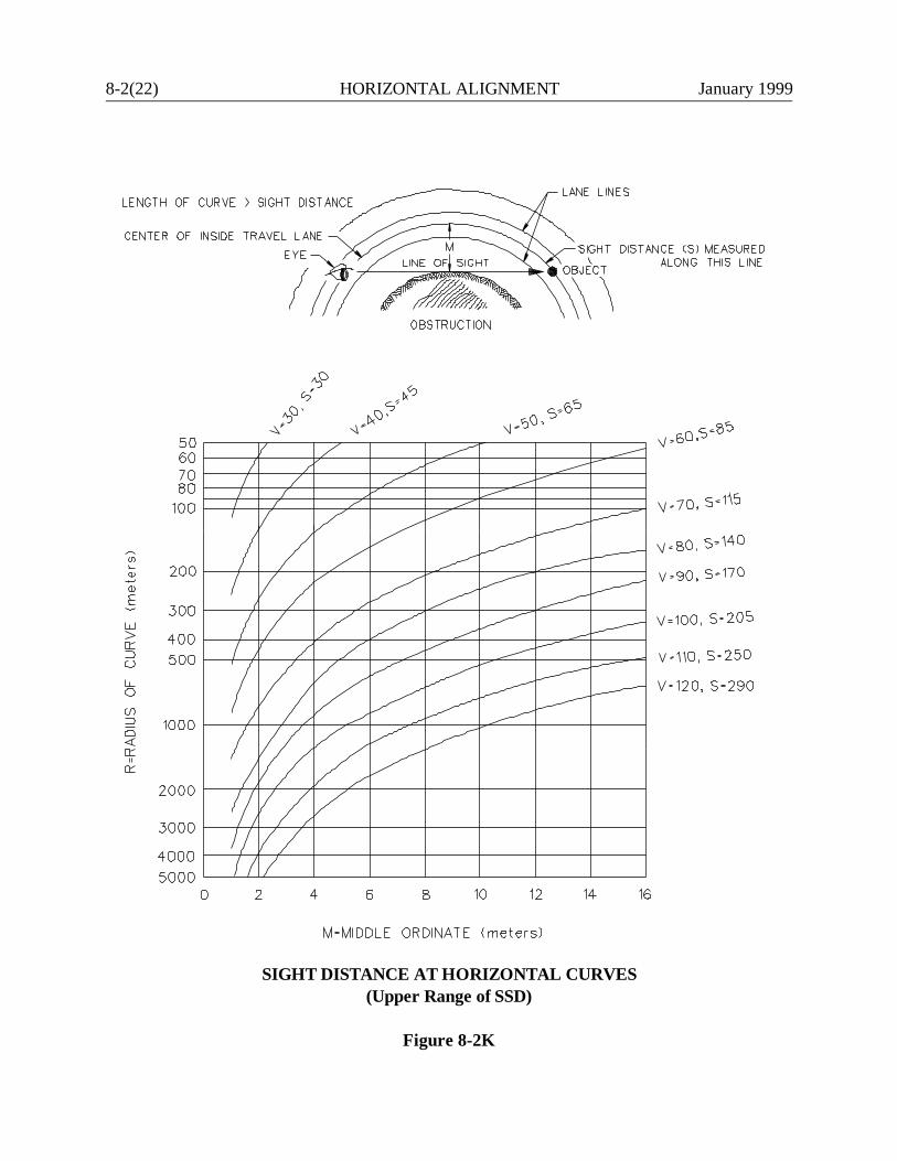
8-2(22) HORIZONTAL ALIGNMENT January 1999
SIGHT DISTANCE AT HORIZONTAL CURVES(Upper Range of SSD)
Figure 8-2K
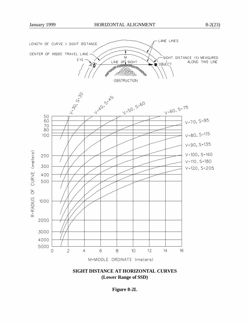
January 1999 HORIZONTAL ALIGNMENT 8-2(23)
SIGHT DISTANCE AT HORIZONTAL CURVES(Lower Range of SSD)
Figure 8-2L
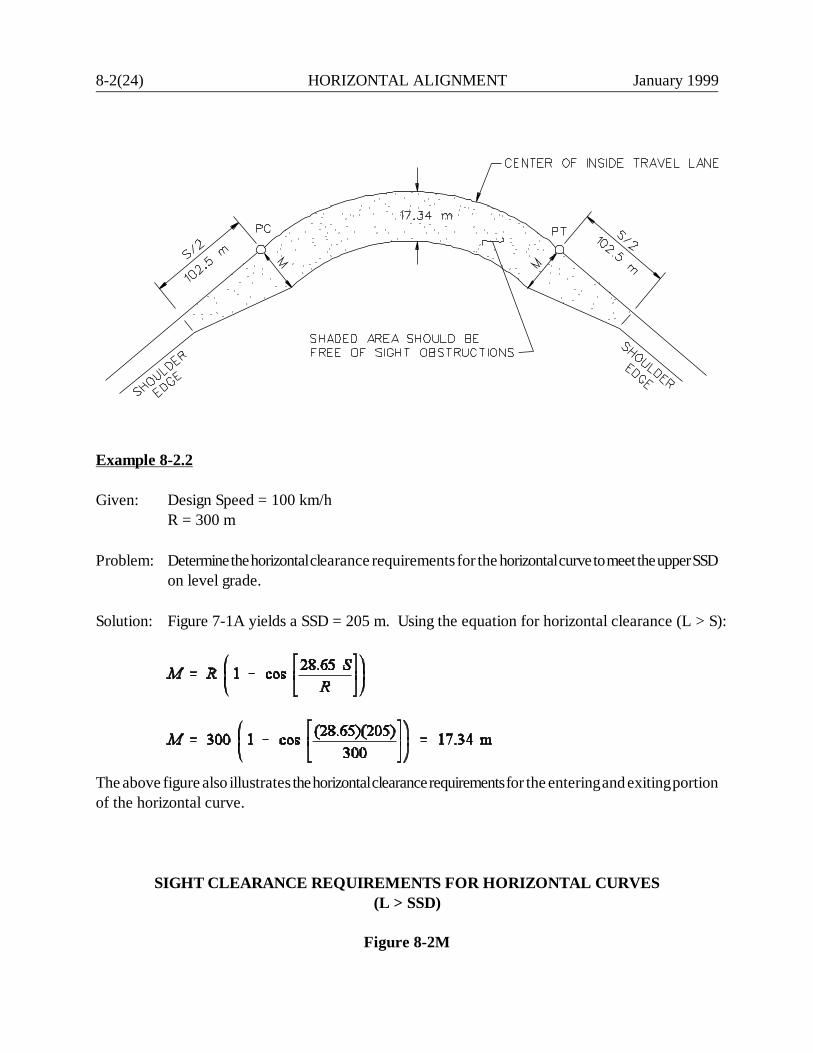
8-2(24) HORIZONTAL ALIGNMENT January 1999
Example 8-2.2
Given: Design Speed = 100 km/hR = 300 m
Problem: Determine the horizontal clearance requirements for the horizontal curve to meet the upper SSDon level grade.
Solution: Figure 7-1A yields a SSD = 205 m. Using the equation for horizontal clearance (L > S):
The above figure also illustrates the horizontal clearance requirements for the entering and exiting portionof the horizontal curve.
SIGHT CLEARANCE REQUIREMENTS FOR HORIZONTAL CURVES(L > SSD)
Figure 8-2M
January 1999 HORIZONTAL ALIGNMENT 8-2(25)
(Equation 8-2.2)
8-2.04.03 Length of Curve < Sight Distance
Where the length of curve is less than the sight distance used in design, the M value from the basicequation will never be reached. As an approximation, the horizontal clearance for these curvesshould be determined as follows:
Step 1: For the given R and S, calculate M assuming L > S.
Step 2: The maximum Mk value will be needed at a point of L/2 beyond the PC. Mk iscalculated from the following proportion:
Where:Mk @ M
Step 3: Locate the point which is on the outside edge of shoulder and a distance of S/2 before thePC.
Step 4: Connect the two points located in Step #’s 2 and 3. The area between this line and theroadway should be clear of all continuous obstructions.
Step 5: A symmetrical application of Step #’s 2 through 4 should be used on the exiting portionof curve.
The Example on Figure 8-2N illustrates the determination of the clearance requirements where L< S.
8-2.04.04 Application
For application, the height of eye is 1070 mm and the height of object is 150 mm. Both the eye andobject are assumed to be in the center of the inside travel lane. The line-of-sight intercept shouldbe unobstructed at least 150 mm above ground level where it is outside of the paved roadway.
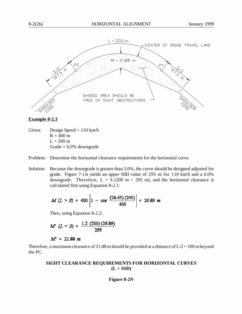
8-2(26) HORIZONTAL ALIGNMENT January 1999
Example 8-2.3
Given: Design Speed = 110 km/hR = 400 mL = 200 mGrade = 6.0% downgrade
Problem: Determine the horizontal clearance requirements for the horizontal curve.
Solution: Because the downgrade is greater than 3.0%, the curve should be designed adjusted forgrade. Figure 7-1A yields an upper SSD value of 295 m for 110 km/h and a 6.0%downgrade. Therefore, L < S (200 m < 295 m), and the horizontal clearance iscalculated first using Equation 8-2.1:
Then, using Equation 8-2.2:
Therefore, a maximum clearance of 21.88 m should be provided at a distance of L/2 = 100 m beyondthe PC.
SIGHT CLEARANCE REQUIREMENTS FOR HORIZONTAL CURVES(L < SSD)
Figure 8-2N
January 1999 HORIZONTAL ALIGNMENT 8-2(27)
8-2.04.05 Longitudinal Barriers
Longitudinal barriers (e.g., bridge rails, guardrail, CMB) may cause sight distance problems athorizontal curves because barriers are placed relatively close to the travel lane (often, 3 m or less)and because their height is greater than 0.6 m.
The designer should check the line of sight over a barrier along a horizontal curve and attempt, ifpractical, to locate the barrier such that it does not block the line of sight. The following should beconsidered:
1. Superelevation. A superelevated roadway will elevate the driver eye and, therefore, improvethe line of sight over the barrier.
2. Grades. The line of sight over a barrier may be improved for a driver on an upgrade andlessened on a downgrade.
3. Barrier Height. The higher the barrier, the more obstructive it will be to the line of sight.
Each barrier location on a horizontal curve will require an individual analysis to determine itsimpacts on the line of sight. The designer must determine the elevation of the driver eye (1070 mmabove the pavement surface), the elevation of the object (150 mm above the pavement surface) andthe elevation of the barrier where the line of sight intercepts the barrier run. If the barrier does blockthe line of sight to a 150-mm object, the designer should consider relocating the barrier or revisingthe horizontal alignment. If the barrier blocks the sight distance needed for minimum SSD on themainline, it will be necessary to obtain a design exception.
8-2.05 Crossover Line
When adjacent lanes have different cross slopes and the driver moves from one lane to the other,there is a pull on the vehicular steering. This pull can cause erratic behavior when it becomesexcessive. To control this, the difference in cross slope on adjacent lanes must be within the limitsshown in Figure 8-2O. This will limit the radius and superelevation rates which may be used undercertain conditions (e.g., when a ramp enters a freeway).
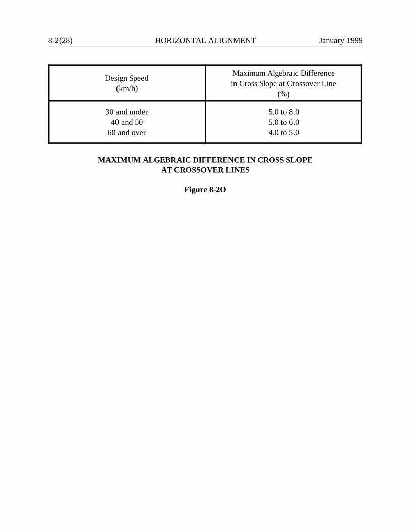
8-2(28) HORIZONTAL ALIGNMENT January 1999
Design Speed(km/h)
Maximum Algebraic Differencein Cross Slope at Crossover Line
(%)
30 and under40 and 50
60 and over
5.0 to 8.05.0 to 6.04.0 to 5.0
MAXIMUM ALGEBRAIC DIFFERENCE IN CROSS SLOPEAT CROSSOVER LINES
Figure 8-2O
January 1999 HORIZONTAL ALIGNMENT 8-3(1)
8-3.0 LOW-SPEED URBAN STREETS
This section presents horizontal alignment criteria for low-speed urban streets (design speed of 70km/h or less). The operating conditions on these facilities is significantly different from those on ruralhighways and high-speed urban highways. Also, urban areas present physical constraints which shouldbe recognized. Therefore, some of the assumptions for horizontal alignment can be legitimatelyrevised for low-speed urban streets. However, much of the criteria in Section 8-2.0 on open highwaysalso applies to low-speed urban streets. Therefore, this section will reference Section 8-2.0 whereapplicable.
8-3.01 General Controls
The criteria in Section 8-2.01 also applies to low-speed urban streets.
8-3.02 Horizontal Curvature
8-3.02.01 Theoretical Discussion
The point mass formula for curvature is also used for low-speed urban streets. However, theassumptions for the values within the formula differ from those for open highways. See the AASHTOA Policy on Geometric Design of Highways and Streets for the theoretical discussion.
For low-speed urban streets, emax = 4.0% once the decision is made that a curve requiressuperelevation. This lower value reflects the problems often encountered when attempting tosuperelevate in urban areas where roadside development is extensive.
8-3.02.02 Application
Figure 8-3A presents the minimum radii for various design speeds for low-speed urban streets. Thedesigner should wherever practical provide horizontal curvature flatter than the minimum radius.
Figure 8-3B presents the minimum radii for which the normal crown (NC) section can be maintainedaround a curve. The values assume that the pavement cross slope is 1.5%, which yields asuperelevation rate of -1.5% for one direction of travel when the normal crown section is maintained.The figure also presents the range of radii for which remove crown (RC) applies. In this range, thecurve must be superelevated at a rate of +1.5% across the entire highway section.

8-3(2) HORIZONTAL ALIGNMENT January 1999
Design Speed(km/h)
emax fmax e + fMinimum Radius
(m)
3040506070
4.0%4.0%4.0%4.0%4.0%
0.3120.2520.2140.1860.163
0.3520.2920.2540.2260.203
204580
130190
MINIMUM RADII ON LOW-SPEED URBAN STREETSFigure 8-3A
DesignSpeed(km/h)
Radius (m)
NormalCrown
RemoveCrown
See Figure8-3C
3040506070
R >R >R >R >R >
2555104178258
25 55
104178258
> R >> R >> R >> R >> R >
224786142204
R <R <R <R <R <
22 47 86 142 204
Note: Flatter radius is based on a theoretical superelevation rate of -1.5%.Sharper radius is based on a theoretical superelevation rate of +1.5%.
RANGE OF RADII FOR NORMAL CROWN SLOPEAND REMOVE CROWN SLOPE
(Cross Slope = 1.5%)
Figure 8-3B
January 1999 HORIZONTAL ALIGNMENT 8-3(3)
Figure 8-3C provides the superelevation rates for combinations of curve radius and design speed forthose curves when NC or RC is inadequate. The following examples illustrate how to use Figures 8-3B and 8-3C.
* * * * * * * *Example 8-3.1
Given: Design speed = 60 km/hRadius = 180 mCross slope = 1.5%
Problem: Determine the superelevation rate.
Solution: Figure 8-3C yields a required superelevation rate of -2.6%. If the normal crown ismaintained throughout the curve, the superelevation rate is -1.5%. Therefore, thenormal crown should be maintained. This is consistent with the NC criteria in Figure8-3B.
Example 8-3.2
Given: Design speed = 60 km/hRadius = 150 mCross slope = 1.5%
Problem: Determine the superelevation rate.
Solution: Figure 8-3C yields a required superelevation rate of +0.3%. The normal crown wouldprovide a rate of -1.5%, which is unacceptable. Therefore, the pavement should besuperelevated at a rate of +1.5% across the entire pavement for ease of design andconstruction. This is consistent with the RC criteria in Figure 8-3B.
Example 8-3.3
Given: Design speed = 60 km/hRadius = 135 mCross slope = 1.5%
Problem: Determine the superelevation rate.

8-3(4) HORIZONTAL ALIGNMENT January 1999
Notes:
1. emax = 4.0% (typical)
2. For the rotation of a 1-lane pavement width, the minimum length will always apply. Theseare:
Design Speed(km/h)
Minimum RunoffLength (m)a
3040506070
2025303540
a Runoff length is measured from the adverse slope removed to full superelevation. SeeSection 8-2.03 for calculation of tangent runout length (from normal crown to adverseslope removed).
3. For the rotation of a 2-lane pavement width, see the discussion in Section 8-2.03 to calculatethe superelevation transition length.
SUPERELEVATION RATES(Low-Speed Urban Streets)
Figure 8-3C
January 1999 HORIZONTAL ALIGNMENT 8-3(5)
Solution: Figure 8-3C yields a required rate of +2.4%. Therefore, the entire pavement shouldbe transitioned and superelevated at this rate.
* * * * * * * *
8-3.02.03 Types of Curvature
The discussion and figures in Section 8-2.02.03 also apply to low-speed urban streets.
8-3.03 Superelevation Development
Once the decision is made to provide superelevation on a low-speed urban street, the methodspresented in Section 8-2.03 will apply. Section 8-2.03 discusses the length of transition, the effectsof the type of curvature (e.g., simple) and the axis of rotation. Note that Figure 8-3C presents thesuperelevation transition lengths for low-speed urban streets where a 1-lane pavement width is beingrotated.
8-3.04 Horizontal Sight Distance
The criteria presented in Section 8-2.04 also apply to horizontal sight distance on low-speed urbanstreets.

8-3(6) HORIZONTAL ALIGNMENT January 1999

January 1999 VERTICAL ALIGNMENT 9-i
Chapter Nine
VERTICAL ALIGNMENT
Table of Contents
Page
9-1.0 DESIGN PRINCIPLES AND PROCEDURES . . . . . . . . . . . . . . . . . . . . . . . . . . . 9-1(1)
9.1.01 General Controls for Vertical Alignment . . . . . . . . . . . . . . . . . . . . . . . 9-1(1) 9-1.02 Coordination of Horizontal and Vertical Alignment . . . . . . . . . . . . . . . 9-1(2)
9-2.0 GRADES . . . . . . . . . . . . . . . . . . . . . . . . . . . . . . . . . . . . . . . . . . . . . . . . . . . . . . . . 9-2(1)
9-2.01 Terrain (Definitions) . . . . . . . . . . . . . . . . . . . . . . . . . . . . . . . . . . . . . . . 9-2(1) 9-2.02 Critical Length of Grade . . . . . . . . . . . . . . . . . . . . . . . . . . . . . . . . . . . . 9-2(1)
9-2.03 Maximum and Minimum . . . . . . . . . . . . . . . . . . . . . . . . . . . . . . . . . . . . 9-2(2) 9-2.04 Truck-Climbing Lanes . . . . . . . . . . . . . . . . . . . . . . . . . . . . . . . . . . . . . . 9-2(5)
9-2.04.01 Warrants . . . . . . . . . . . . . . . . . . . . . . . . . . . . . . . . . . . . . . . 9-2(5) 9-2.04.02 Capacity Analysis . . . . . . . . . . . . . . . . . . . . . . . . . . . . . . . . 9-2(5) 9-2.04.03 Design . . . . . . . . . . . . . . . . . . . . . . . . . . . . . . . . . . . . . . . . . 9-2(6)
9-3.0 VERTICAL CURVES . . . . . . . . . . . . . . . . . . . . . . . . . . . . . . . . . . . . . . . . . . . . . . 9-3(1)
9-3.01 General . . . . . . . . . . . . . . . . . . . . . . . . . . . . . . . . . . . . . . . . . . . . . . . . . . 9-3(1) 9-3.02 Crest Vertical Curves . . . . . . . . . . . . . . . . . . . . . . . . . . . . . . . . . . . . . . . 9-3(1) 9-3.03 Sag Vertical Curves . . . . . . . . . . . . . . . . . . . . . . . . . . . . . . . . . . . . . . . . 9-3(5)
9-4.0 VERTICAL CLEARANCES . . . . . . . . . . . . . . . . . . . . . . . . . . . . . . . . . . . . . . . . . . 9-4(1)
9-5.0 REFERENCES . . . . . . . . . . . . . . . . . . . . . . . . . . . . . . . . . . . . . . . . . . . . . . . . . . . . 9-5(1)

9-ii VERTICAL ALIGNMENT January 1999
January 1999 VERTICAL ALIGNMENT 9-1(1)
Chapter NineVERTICAL ALIGNMENT
9-1.0 DESIGN PRINCIPLES AND PROCEDURES
9-1.01 General Controls for Vertical Alignment
As discussed elsewhere in Chapter Nine, the design of vertical alignment involves, to a large extent,complying with specific limiting criteria. These include maximum and minimum grades, sightdistance at vertical curves and vertical clearances. In addition, the designer should adhere to certaingeneral design principles and controls which will determine the overall safety of the facility and willenhance the aesthetic appearance of the highway. These design principles for vertical alignmentinclude:
1. Consistency. Use a smooth grade line with gradual changes, consistent with the type ofhighway and character of terrain, rather than a line with numerous breaks and short lengthsof tangent grades.
2. Environmental Impacts. Vertical alignment should be properly coordinated withenvironmental impacts (e.g., encroachment onto wetlands).
3. Long Grades. On a long ascending grade, it is preferable to place the steepest grade at thebottom and flatten the grade near the top. It is also preferable to break the sustained gradewith short intervals of flatter grades.
4. Intersections. Maintain moderate grades through intersections to facilitate turningmovements. See Chapter Eleven for specific information on vertical alignment throughintersections.
5. Roller Coaster. Avoid using "roller-coaster" type profiles. Roller-coaster profiles are wherethe horizontal alignment is generally straight and roadway profile closely follows a rollingnatural ground line. This type of profile may be proposed in the interest of economy, but itis aesthetically undesirable and may be more difficult to drive.
6. Broken-Back Curvature. Avoid "broken-back" grade lines (two crest or sag vertical curvesseparated by a short tangent). One long vertical curve is more desirable.
9-1(2) VERTICAL ALIGNMENT January 1999
7. Sags. Avoid using sag vertical curves in cut sections unless adequate drainage can beprovided.
8. Coordination with Natural/Man-Made Features. The vertical alignment should be properlycoordinated with the natural topography, available right-of-way, utilities, roadsidedevelopment and natural/man-made drainage patterns.
9-1.02 Coordination of Horizontal and Vertical Alignment
Horizontal and vertical alignment should not be designed separately, especially for projects on newalignment. Their importance demands that the designer carefully evaluate the interdependence ofthe two highway design features. This will enhance highway safety and improve the facility'soperation. The following should be considered in the coordination of horizontal and verticalalignment:
1. Balance. Curvature and grades should be in proper balance. Maximum curvature with flatgrades or flat curvature with maximum grades does not achieve this desired balance. Acompromise between the two extremes produces the best design relative to safety, capacity,ease and uniformity of operations and aesthetics.
2. Coordination. Vertical curvature superimposed upon horizontal curvature (i.e., vertical andhorizontal P.I.'s at approximately the same stations) generally results in a more pleasingappearance and reduces the number of sight distance restrictions. Successive changes inprofile not in combination with the horizontal curvature may result in a series of humpsvisible to the driver for some distance, which may produce an unattractive design. However,under some circumstances, superimposing the horizontal and vertical alignment must betempered somewhat by Comment #'s 3 and 4 as follows.
3. Crest Vertical Curves. Do not introduce sharp horizontal curvature at or near the top ofpronounced crest vertical curves. This is undesirable because the driver cannot perceive thehorizontal change in alignment, especially at night when headlight beams project straightahead into space. This problem can be avoided if the horizontal curvature leads the verticalcurvature or by using design values which well exceed the minimums.
4. Sag Vertical Curves. Do not introduce sharp horizontal curves at or near the low point ofpronounced sag vertical curves or at the bottom of steep vertical grades. Because visibilityto the road ahead is foreshortened, only flat horizontal curvature will avoid an undesirable,distorted appearance. At the bottom of long grades, vehicular speeds often are higher,particularly for trucks, and erratic operations may occur, especially at night.
January 1999 VERTICAL ALIGNMENT 9-1(3)
5. Intersections. At intersections, horizontal and vertical alignment should be as flat aspractical to provide designs which produce sufficient sight distance and gradients forvehicles to slow or stop. See Chapter Eleven.
6. Divided Highways. On divided facilities with wide medians, it is frequently advantageousto provide independent alignments for the two one-way roadways. Where traffic justify adivided facility, a superior design with minimal additional cost generally can result from theuse of independent alignments.
7. Residential Areas. Design the alignment to minimize nuisance factors to neighborhoods.Generally, a depressed facility makes the highway less visible and reduces the noise toadjacent residents. Minor adjustment to the horizontal alignment may increase the bufferzone between the highway and residential areas.
8. Aesthetics. Layout alignment to enhance attractive scenic views of rivers, rock formations,parks, golf courses, etc. The highway should head into rather than away from those viewsthat are considered to be aesthetically pleasing. The highway should fall towards thosefeatures of interest at a low elevation and rise toward those features which are best seen frombelow or in silhouette against the sky.
The designer should coordinate the layout of the horizontal and vertical alignment as early aspractical in the design process. Alignment layouts are typically completed after the topography andground line have been drafted. The designer should use the computer visualization programs withinCADD to visualize how the layout will appear in the field. The designer should review severalalternatives to ensure that the most pleasing and practical design is selected.

9-1(4) VERTICAL ALIGNMENT January 1999
January 1999 VERTICAL ALIGNMENT 9-2(1)
9-2.0 GRADES
9-2.01 Terrain (Definitions)
1. Level. Highway sight distances are either long or could be made long without major constructionexpense. The terrain is generally considered to be flat, which has minimal impact on vehicularperformance.
2. Rolling. The natural slopes consistently rise above and fall below the roadway grade and,occasionally, steep slopes present some restriction to the desirable highway alignment. In general,rolling terrain generates steeper grades, causing trucks to reduce speeds below those of passengercars.
3. Mountainous. Longitudinal and transverse changes in elevation are abrupt, and benching and sidehill excavation are frequently required to provide the desirable highway alignment. Mountainousterrain aggravates the performance of trucks relative to passenger cars, resulting in some trucksoperating at crawl speeds.
In Connecticut, only the rolling level terrain criteria will be applicable because, even though a roadway maypass through a level or hilly site, the area as a whole is still considered to be rolling terrain.
9-2.02 Critical Length of Grade
In addition to the maximum grade, the designer must consider the length of the grade. The criticallength of grade is the maximum length of a specific upgrade on which a loaded truck can operatewithout an unreasonable reduction in speed. The highway gradient in combination with the lengthof grade will determine the truck speed reduction on upgrades. The following will apply to thecritical length of grade:
1. Design Vehicle. For critical-length-of-grade determinations, the Department has adoptedthe 180 kilograms/kiloWatt (kg/kW) truck as the most representative design vehicle forConnecticut.
2. Criteria. Figure 9-2A provides the critical lengths of grade for a given percent grade andacceptable truck speed reduction. Although these figures are based on an initial truck speedof 90 km/h, they apply to any design speed. For design purposes, use the 15 km/h speedreduction curve to determine if the critical length of grade is exceeded.
3. Measurement. Vertical curves are part of the length of grade. Figure 9-2B illustrates howto measure the length of grade to determine the critical length of grade from Figure 9-2A.
9-2(2) VERTICAL ALIGNMENT January 1999
4. Highway Types. The critical-length-of-grade criteria applies equally to two-lane or multi-lane highways and applies equally to urban and rural facilities.
5. Application. If the critical length of grade is exceeded, the designer should either flatten thegrade, if practical, or should evaluate the need for a truck-climbing lane (see Section 9-2.04).
* * * * * * * * * *Example 9-2.1
Given: Level ApproachG = +4%L = 350 m (length of grade)Rural Arterial
Problem: Determine if the critical length of grade is exceeded.
Solution: Figure 9-2A yields a critical length of grade of 280 m for a 15-km/h speed reduction.The length of grade (L) exceeds this value. Therefore, the designer should flatten thegrade, if practical, or evaluate the need for a climbing lane.
9-2.03 Maximum and Minimum
The highway gradient will significantly impact vehicular operations and safety. The Department hasadopted criteria for maximum gradient based on functional classification, urban/rural location, designspeed and project scope of work. These values are presented in Chapters Two, Four and Five.Flatter grades should be used wherever practical.
The minimum longitudinal gradient is 0.5%. This applies to all highways with or without curbs.
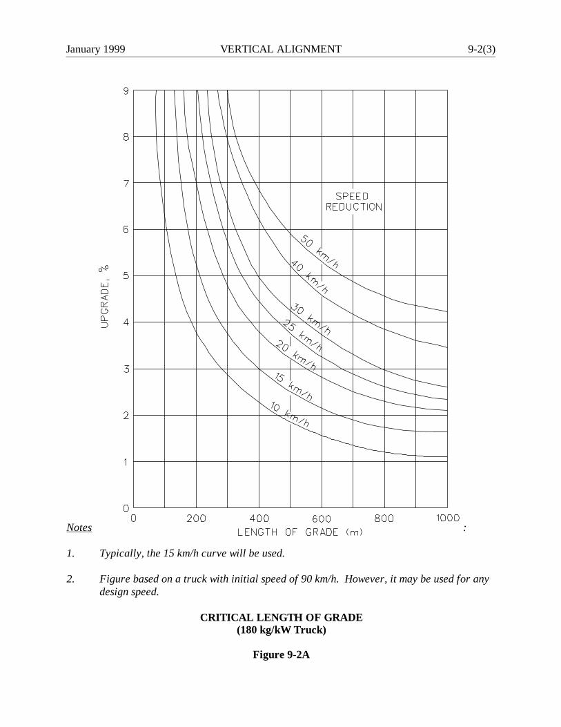
January 1999 VERTICAL ALIGNMENT 9-2(3)
Notes :
1. Typically, the 15 km/h curve will be used.
2. Figure based on a truck with initial speed of 90 km/h. However, it may be used for anydesign speed.
CRITICAL LENGTH OF GRADE(180 kg/kW Truck)
Figure 9-2A
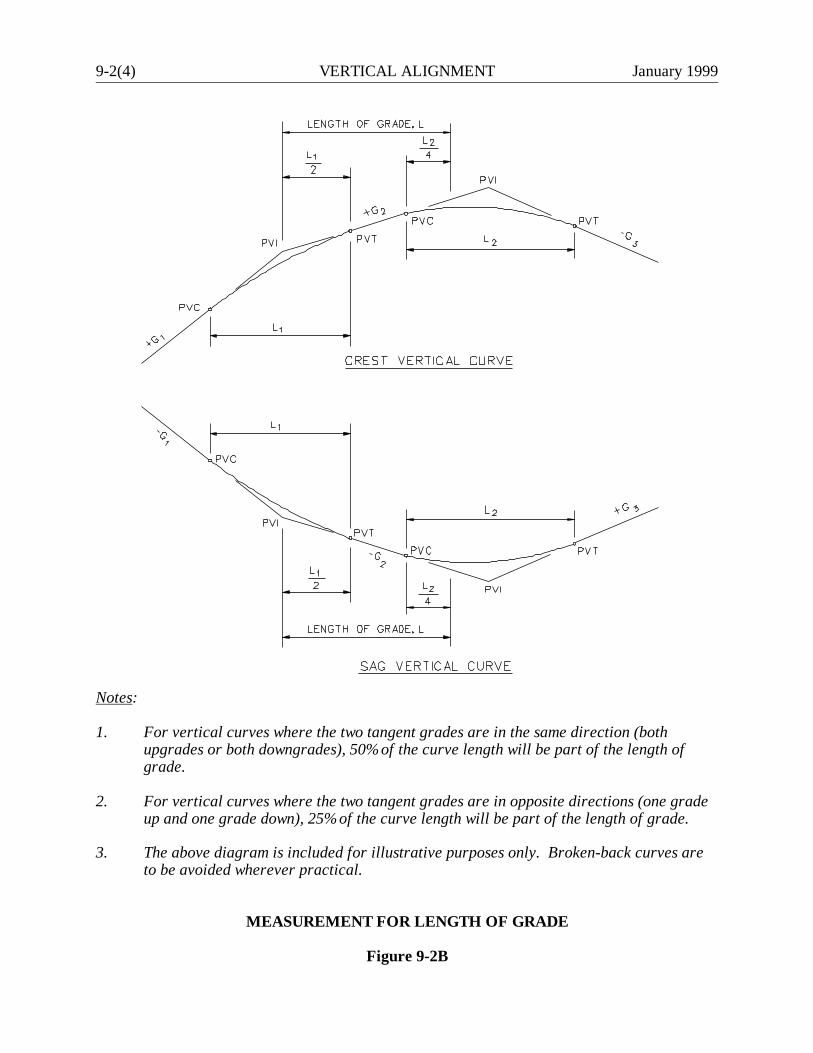
9-2(4) VERTICAL ALIGNMENT January 1999
Notes:
1. For vertical curves where the two tangent grades are in the same direction (bothupgrades or both downgrades), 50% of the curve length will be part of the length ofgrade.
2. For vertical curves where the two tangent grades are in opposite directions (one gradeup and one grade down), 25% of the curve length will be part of the length of grade.
3. The above diagram is included for illustrative purposes only. Broken-back curves areto be avoided wherever practical.
MEASUREMENT FOR LENGTH OF GRADE
Figure 9-2B
January 1999 VERTICAL ALIGNMENT 9-2(5)
9-2.04 Truck-Climbing Lanes
9-2.04.01 Warrants
A truck-climbing lane may be warranted to allow a specific upgrade to operate at an acceptable levelof service. A truck-climbing lane will generally be warranted if the following conditions are satisfied:
1. the critical length of grade is exceeded for the 15 km/h speed reduction curve (see Figure9-2A; and
2. one of the following conditions exists:
a. the level of service (LOS) on the upgrade is E or F, or
b. there is a reduction of two or more LOS when moving from the approach segmentto the upgrade; and
3. the construction costs and the construction impacts (e.g., environmental, right-of-way) areconsidered reasonable.
Truck-climbing lanes may also be warranted where the above criteria are not met if, for example,there is an adverse accident experience on the upgrade related to slow-moving trucks. In addition,on 4-lane freeways if the speed profile reveals an operating speed of less than 50 km/h at any point,a climbing lane will be warranted regardless of the results of the capacity analysis.
9-2.04.02 Capacity Analysis
The objective of the capacity analysis procedure is to determine if the warranting criteria in Section9-2.04.01 are met. This is accomplished by calculating the service flow rate for each LOS level (Athrough D) and comparing this to the actual flow rate on the upgrade. Because a LOS worse thanD warrants a truck-climbing lane, it is not necessary to calculate the service flow rate for LOS E.
The designer should analyze the operations on the grade using the procedures set forth in theHighway Capacity Manual. Note that the default values for determining the appropriate passengercar equivalent (E) values in the Highway Capacity Software (HCS) are acceptable for determiningthe LOS on climbing lanes (i.e., the default truck in the HCS is acceptable).
9-2(6) VERTICAL ALIGNMENT January 1999
To determine if a climbing lane is warranted, these basic steps should be followed:
1. Review the project to determine if a climbing lane should be considered. Steep and/or longgrades should be considered for climbing lanes.
2. For highways with a single grade, the critical length of grade can be directly determined fromFigure 9-2A. However, most highways have a continuous series of grades. Often, it isnecessary to find the impact of a series of significant grades in succession. If several differentgrades are present, then a speed profile must be developed using Figure 9-2C and theprocedures set forth in the Highway Capacity Manual. If there is a 15 km/h reduction, thenthe first warrant is met. The speed profile should note the truck speed at the beginning of thefull-width climbing lane, the PVC, the PVT and the end of the full-width lane.
3. Determine the total traffic volumes, the truck volumes on the grade and those on theapproach prior to the upgrade.
4. Using the procedures set forth in the Highway Capacity Manual, determine the appropriatelevel of service for both the approach and the grade. If the level of service on the upgradeis E/F or if there is a reduction of 2 or more levels of service on the upgrade from theapproaches, then the second warrant is met.
9-2.04.03 Design
Figure 9-2D summarizes the design criteria for climbing lanes. It should be noted, that actualplacement of the tapers for the beginning and end of climbing lanes should consider sight distanceto the tapers. The placement of the terminal taper should maximize the available sight distance. Theshoulder width along the climbing lane will be the normal shoulder width for the appropriate highwayclassification. The tables in Chapters Four and Five provide the shoulder widths.
The Traffic Standard Details provide the typical signing and pavement marking patterns for theclimbing lanes.
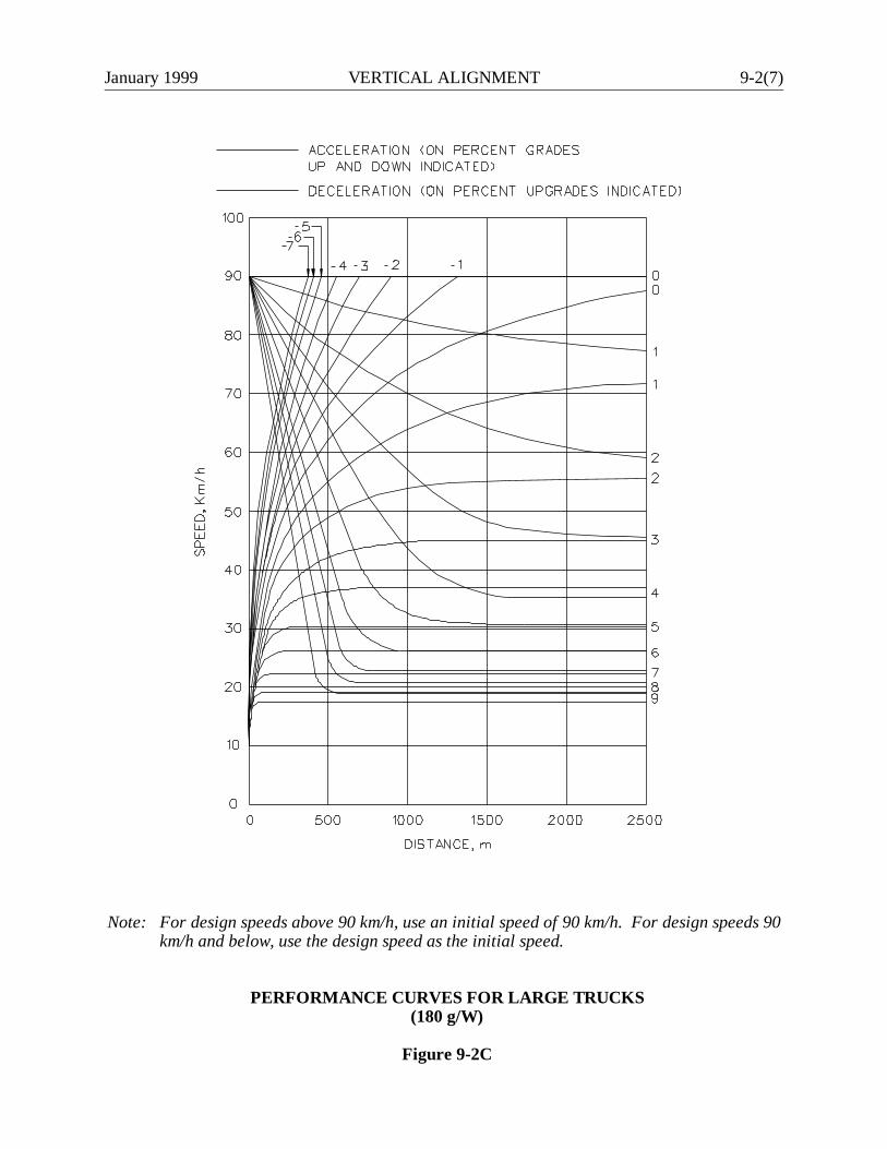
January 1999 VERTICAL ALIGNMENT 9-2(7)
Note: For design speeds above 90 km/h, use an initial speed of 90 km/h. For design speeds 90km/h and below, use the design speed as the initial speed.
PERFORMANCE CURVES FOR LARGE TRUCKS(180 g/W)
Figure 9-2C
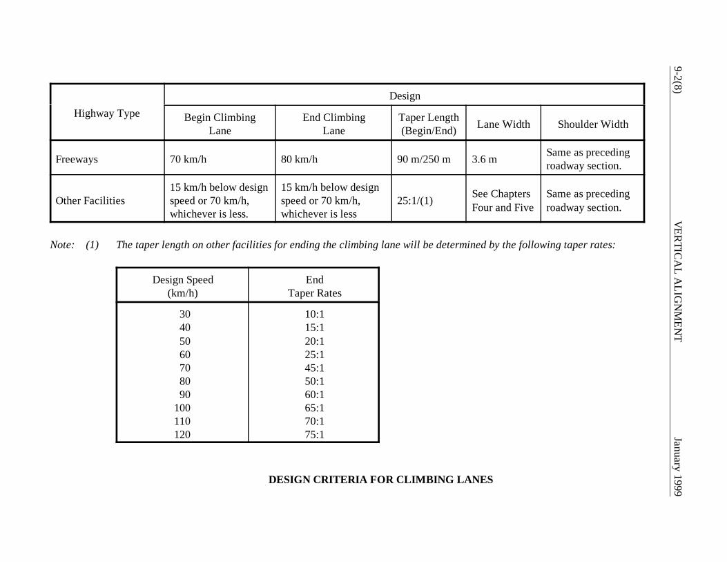
9-2(8)V
ERTIC
AL A
LIGN
MEN
TJanuary 1999
Highway TypeDesign
Begin ClimbingLane
End ClimbingLane
Taper Length(Begin/End) Lane Width Shoulder Width
Freeways 70 km/h 80 km/h 90 m/250 m 3.6 m Same as precedingroadway section.
Other Facilities15 km/h below designspeed or 70 km/h,whichever is less.
15 km/h below designspeed or 70 km/h,whichever is less
25:1/(1) See ChaptersFour and Five
Same as precedingroadway section.
Note: (1) The taper length on other facilities for ending the climbing lane will be determined by the following taper rates:
Design Speed(km/h)
EndTaper Rates
30405060708090
100110120
10:115:120:125:145:150:160:165:170:175:1
DESIGN CRITERIA FOR CLIMBING LANES
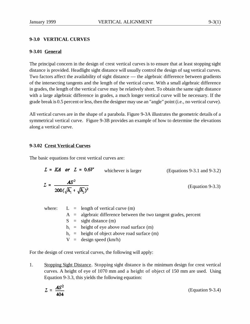
January 1999 VERTICAL ALIGNMENT 9-3(1)
(Equation 9-3.3)
9-3.0 VERTICAL CURVES
9-3.01 General
The principal concern in the design of crest vertical curves is to ensure that at least stopping sightdistance is provided. Headlight sight distance will usually control the design of sag vertical curves.Two factors affect the availability of sight distance — the algebraic difference between gradientsof the intersecting tangents and the length of the vertical curve. With a small algebraic differencein grades, the length of the vertical curve may be relatively short. To obtain the same sight distancewith a large algebraic difference in grades, a much longer vertical curve will be necessary. If thegrade break is 0.5 percent or less, then the designer may use an "angle" point (i.e., no vertical curve).
All vertical curves are in the shape of a parabola. Figure 9-3A illustrates the geometric details of asymmetrical vertical curve. Figure 9-3B provides an example of how to determine the elevationsalong a vertical curve.
9-3.02 Crest Vertical Curves
The basic equations for crest vertical curves are:
whichever is larger (Equations 9-3.1 and 9-3.2)
where: L = length of vertical curve (m)A = algebraic difference between the two tangent grades, percentS = sight distance (m)h1 = height of eye above road surface (m)h2 = height of object above road surface (m)V = design speed (km/h)
For the design of crest vertical curves, the following will apply:
1. Stopping Sight Distance. Stopping sight distance is the minimum design for crest verticalcurves. A height of eye of 1070 mm and a height of object of 150 mm are used. UsingEquation 9-3.3, this yields the following equation:
(Equation 9-3.4)

9-3(2) VERTICAL ALIGNMENT January 1999
M = Mid-ordinate (m)Z = Any tangent offset (m)L = Horizontal length of vertical curve (m)X = Horizontal distance from PVC or PVT to any ordinate "Z" (m)G1 & G2 = Rates of grade, expressed algebraically, in percent
ALL EXPRESSIONS TO BE CALCULATED ALGEBRAICALLY
For offset "Z" at distance "X" from PVC or PVT:
For slope "S" of a line tangent to any point on the vertical curve at an "X" distance measured from the PVC:
CALCULATING HIGH OR LOW POINT ON CURVE
Where "XT" equals the horizontal distance from the PVC to the high or low point on the curve in meters.Elevation of high or low point on curve equals:
SYMMETRICAL VERTICAL CURVE EQUATIONS
Figure 9-3A
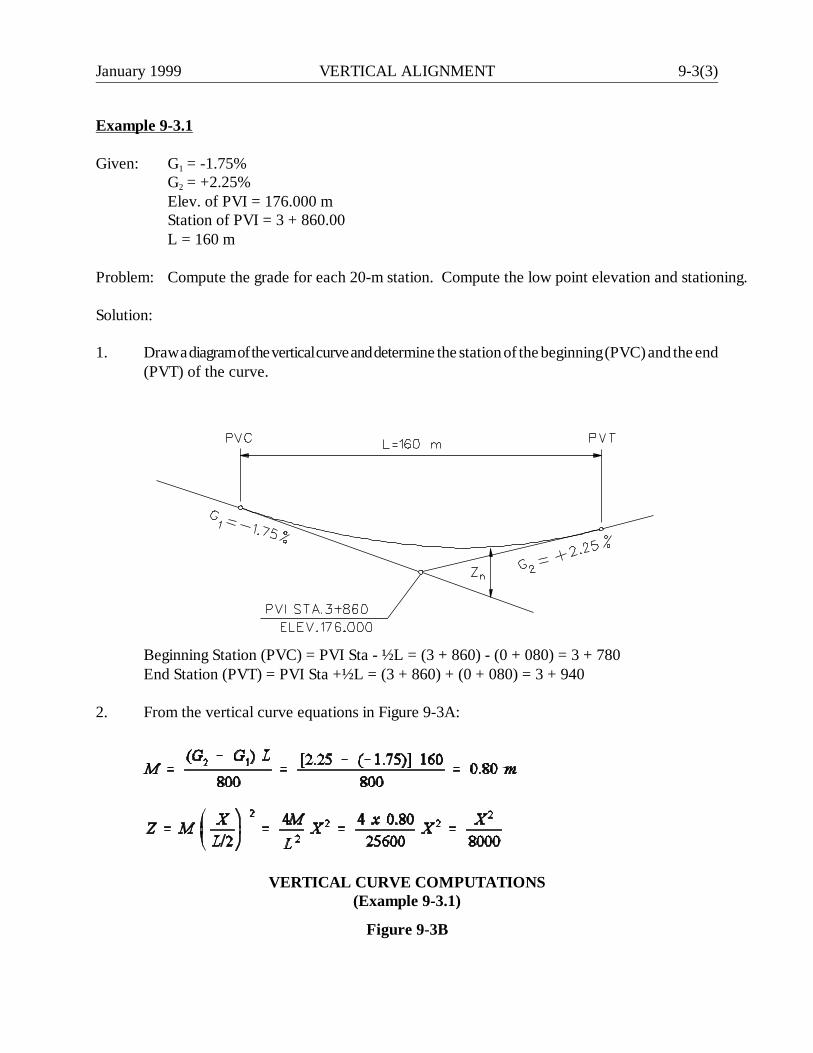
January 1999 VERTICAL ALIGNMENT 9-3(3)
Example 9-3.1
Given: G1 = -1.75%G2 = +2.25%Elev. of PVI = 176.000 mStation of PVI = 3 + 860.00L = 160 m
Problem: Compute the grade for each 20-m station. Compute the low point elevation and stationing.
Solution:
1. Draw a diagram of the vertical curve and determine the station of the beginning (PVC) and the end(PVT) of the curve.
Beginning Station (PVC) = PVI Sta - ½L = (3 + 860) - (0 + 080) = 3 + 780End Station (PVT) = PVI Sta +½L = (3 + 860) + (0 + 080) = 3 + 940
2. From the vertical curve equations in Figure 9-3A:
VERTICAL CURVE COMPUTATIONS(Example 9-3.1)
Figure 9-3B

9-3(4) VERTICAL ALIGNMENT January 1999
Example 9-3.1Solution: (continued)
3. Set up a table to show the vertical curve elevations at the 20-meter stations:
Station(n) Inf.
TangentElevation(Along G1)
X X2 Zn
GradeElevation
3 + 7803 + 8003 + 8203 + 8403 + 8603 + 8803 + 9003 + 9203 + 940
PVC
PVI
PVT
177.400177.050176.700176.350176.000175.650175.300174.950174.600
020406080100120140160
0400160036006400
10 00014 40019 60025 600
00.0500.2000.4500.8001.2501.8002.4503.200
177.400177.100176.900176.800176.800176.900177.100177.400177.800
4. Calculating low point:
therefore, the Station at low point is:
(3 + 780) + (0 + 070) = (3 + 850)
elevation of low point on curve equals:
VERTICAL CURVE COMPUTATIONS(Example 9-3.1)
(Continued)
Figure 9-3B
January 1999 VERTICAL ALIGNMENT 9-3(5)
Figure 9-3C presents the K-values for crest vertical curves. These values have beencalculated by using the SSD values from Figure 7-1A and Equation 9-3.4.
2. Grade Adjustments. When determining S for crest vertical curves, the designer shouldconsider the effects of grade on stopping sight distance (SSD). The following thresholds maybe used for determining the thresholds for "Level" K-values:
V > 80 km/h : -1% < G < +1%V < 80 km/h : -2% < G < +2%
The selection of "G" at a crest vertical curve will depend on which grade is steeper andwhether the roadway is one way or two way. On a 1-way roadway, "G" should always be thegrade on the far side of the crest when considering the direction of travel. On a 2-wayroadway, "G" should always be the steeper of the two grades on either side of the crest.
For design exception purposes, only the “Level” SSD value will require an exception. Fordesigns where, because of rounding in the charts, the “Level” SSD is met but not the K-value, an exception will not be required.
3. Decision Sight Distance. Section 7-2.0 discusses the general warrants for decision sightdistance. The procedure will determine the appropriate "S" and height of object for thespecific site conditions. These values should then be used in Equation 9-3.3 to determine thenecessary curve length at the site.
4. Drainage. Drainage should be considered in the design of crest vertical curves where curbedsections are used. Drainage problems should not be experienced if the vertical curvature issharp enough so that a minimum longitudinal grade of at least 0.3% is reached at a pointabout 15 m from either side of the apex. To ensure that this objective is achieved, the lengthof the vertical curve should be based upon a K-value of 50 or less. For crest vertical curveson curbed sections where this K-value is exceeded, the drainage design should be morecarefully evaluated near the apex.
For uncurbed sections of highway, drainage should not be a problem at crest vertical curves.
9-3.03 Sag Vertical Curves
Headlight sight distance is the primary design control for sag vertical curves. The height of theheadlights is assumed to be 600 mm. The upward divergence of the beam is 1° from the longitudinalaxis of the vehicle. The curvature of the sag should allow sufficient pavement illumination to provideadequate sight distance. These criteria yield the following equations:
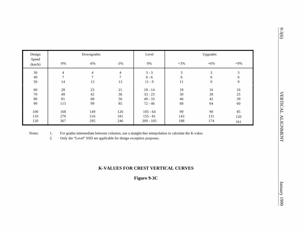
9-3(6)V
ERTIC
AL A
LIGN
MEN
TJanuary 1999
DesignSpeed(km/h)
Downgrades Level Upgrades
-9% -6% -3% 0% +3% +6% +9%
304050
47
14
47
13
47
13
3 - 36 - 6
11 - 9
36
11
369
369
60708090
284981
115
23426899
21365685
18 - 1433 - 2349 - 3372 - 46
18304668
16284264
16253960
100110120
168270367
149216295
126181246
105 - 64155 - 81
209 - 105
99143188
90131174
85120161
Notes: 1. For grades intermediate between columns, use a straight-line interpolation to calculate the K-value.2. Only the “Level” SSD are applicable for design exception purposes.
K-VALUES FOR CREST VERTICAL CURVES
Figure 9-3C

January 1999 VERTICAL ALIGNMENT 9-3(7)
whichever is larger (Equations 9-3.5 and 9-3.6)
(Equation 9-3.7)
For the design of sag vertical curves, the following will apply:
1. Stopping Sight Distance (SSD). Figure 9-3D presents the K-values for sag vertical curves.These values have been calculated by using the SSD values from Figure 7-1A and Equation9-3.7.
2. Grade Adjustments. Section 9-3.02 discusses the application of SSD to crest vertical curvespertaining to the grade correction. The grade correction and the thresholds also apply to sagvertical curves.
For design exception purposes, only the “Level” SSD value will require an exception. Fordesigns where, because of rounding in the charts, the “Level” SSD is met but not the K-value, an exception will not be required.
3. Decision Sight Distance. Section 7-2.0 discusses the general warrants for decision sightdistance. The procedure will determine the appropriate "S" and height of object for thespecific site conditions. These values should then be used in Equation 9-3.7 to determine thenecessary curve length at the site.
4. Drainage. Drainage considerations also impact the design of sag curves. The criteria is thesame as for crest vertical curves, which yields a K = 50 for the maximum length of curve.Where this K value is exceeded, the designer should consider special drainage treatments,especially on curbed pavements. In addition, the designer should avoid the placement ofbridges or other structures at the low point of sag vertical curves because of the potentialdrainage problems.
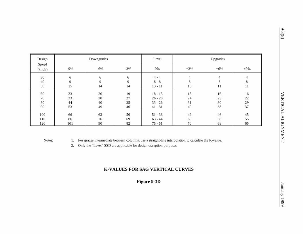
9-3(8)V
ERTIC
AL A
LIGN
MEN
TJanuary 1999
DesignSpeed(km/h)
Downgrades Level Upgrades
-9% -6% -3% 0% +3% +6% +9%
304050
69
15
69
14
69
14
4 - 48 - 8
13 - 11
48
13
48
11
48
11
60708090
23334453
20304049
19273546
18 - 1526 - 2033 - 2641 - 31
18243140
16233038
16222937
100110120
6686
101
627690
566982
51 - 3863 - 4475 - 51
496070
465868
455565
Notes: 1. For grades intermediate between columns, use a straight-line interpolation to calculate the K-value.2. Only the “Level” SSD are applicable for design exception purposes.
K-VALUES FOR SAG VERTICAL CURVES
Figure 9-3D
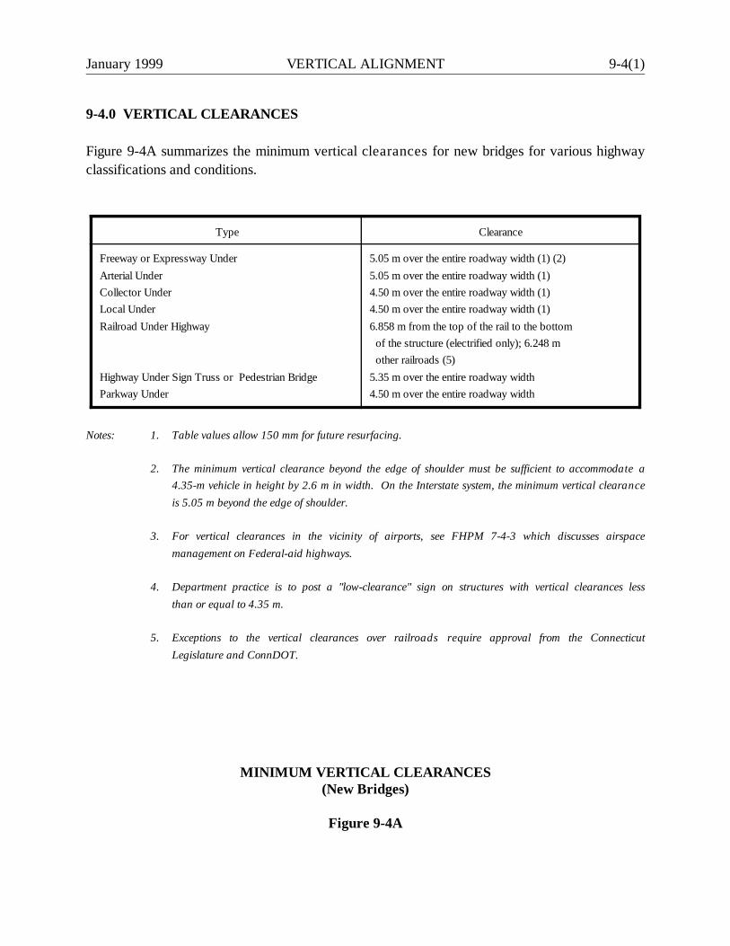
January 1999 VERTICAL ALIGNMENT 9-4(1)
9-4.0 VERTICAL CLEARANCES
Figure 9-4A summarizes the minimum vertical clearances for new bridges for various highwayclassifications and conditions.
Type Clearance
Freeway or Expressway UnderArterial UnderCollector UnderLocal UnderRailroad Under Highway
Highway Under Sign Truss or Pedestrian BridgeParkway Under
5.05 m over the entire roadway width (1) (2)5.05 m over the entire roadway width (1)4.50 m over the entire roadway width (1)4.50 m over the entire roadway width (1)6.858 m from the top of the rail to the bottom of the structure (electrified only); 6.248 m other railroads (5)5.35 m over the entire roadway width4.50 m over the entire roadway width
Notes: 1. Table values allow 150 mm for future resurfacing.
2. The minimum vertical clearance beyond the edge of shoulder must be sufficient to accommodate a4.35-m vehicle in height by 2.6 m in width. On the Interstate system, the minimum vertical clearanceis 5.05 m beyond the edge of shoulder.
3. For vertical clearances in the vicinity of airports, see FHPM 7-4-3 which discusses airspacemanagement on Federal-aid highways.
4. Department practice is to post a "low-clearance" sign on structures with vertical clearances lessthan or equal to 4.35 m.
5. Exceptions to the vertical clearances over railroads require approval from the ConnecticutLegislature and ConnDOT.
MINIMUM VERTICAL CLEARANCES(New Bridges)
Figure 9-4A

9-4(2) VERTICAL ALIGNMENT January 1999
January 1999 VERTICAL ALIGNMENT 9-5(1)
9-5.0 REFERENCES
1. A Policy on Geometric Design of Highways and Streets, AASHTO, 1994.
2. Highway Capacity Manual, TRB, 1994.

9-5(2) VERTICAL ALIGNMENT January 1999

January 1999 CROSS SECTIONS 10-i
Chapter Ten
CROSS SECTIONS
Table of Contents
Page
10-1.0 ROADWAY SECTION . . . . . . . . . . . . . . . . . . . . . . . . . . . . . . . . . . . . . . . . . 10-1(1)
10-1.01 Travel Lanes . . . . . . . . . . . . . . . . . . . . . . . . . . . . . . . . . . . . . . . . . 10-1(1)
10-1.01.01 Width . . . . . . . . . . . . . . . . . . . . . . . . . . . . . . . . . . . 10-1(1) 10-1.01.02 Cross Slope . . . . . . . . . . . . . . . . . . . . . . . . . . . . . . . 10-1(1)
10-1.02 Shoulders . . . . . . . . . . . . . . . . . . . . . . . . . . . . . . . . . . . . . . . . . . . 10-1(2)
10-1.02.01 Shoulder Widths/Types . . . . . . . . . . . . . . . . . . . . . . 10-1(2) 10-1.02.02 Shoulder Cross Slope . . . . . . . . . . . . . . . . . . . . . . . 10-1(2)
10-1.03 Turn Lanes . . . . . . . . . . . . . . . . . . . . . . . . . . . . . . . . . . . . . . . . . . 10-1(3) 10-1.04 Parking Lanes . . . . . . . . . . . . . . . . . . . . . . . . . . . . . . . . . . . . . . . . 10-1(4)
10-1.05 Curbs . . . . . . . . . . . . . . . . . . . . . . . . . . . . . . . . . . . . . . . . . . . . . . 10-1(4)
10-1.05.01 Types . . . . . . . . . . . . . . . . . . . . . . . . . . . . . . . . . . . 10-1(5) 10-1.05.02 Safety . . . . . . . . . . . . . . . . . . . . . . . . . . . . . . . . . . . 10-1(5) 10-1.05.03 Application on Low-Speed Roads/Streets . . . . . . . . 10-1(5) 10-1.05.04 Application on High-Speed Highways . . . . . . . . . . . . 10-1(6)
10-2.0 ROADSIDE ELEMENTS . . . . . . . . . . . . . . . . . . . . . . . . . . . . . . . . . . . . . . . 10-2(1)
10-2.01 Sidewalks . . . . . . . . . . . . . . . . . . . . . . . . . . . . . . . . . . . . . . . . . . . 10-2(1)
10-2.01.01 Guidelines for Sidewalk Construction . . . . . . . . . . . . . 10-2(1) 10-2.01.02 Sidewalk Design Criteria . . . . . . . . . . . . . . . . . . . . . . . 10-2(1)
10-2.02 Fill and Cut Slopes . . . . . . . . . . . . . . . . . . . . . . . . . . . . . . . . . . . . 10-2(2) 10-2.03 Utility Placement . . . . . . . . . . . . . . . . . . . . . . . . . . . . . . . . . . . . . . 10-2(3)
10-3.0 MEDIANS . . . . . . . . . . . . . . . . . . . . . . . . . . . . . . . . . . . . . . . . . . . . . . . . . . . 10-3(1)
10-3.01 Median Widths . . . . . . . . . . . . . . . . . . . . . . . . . . . . . . . . . . . . . . . 10-3(1) 10-3.02 Median Types . . . . . . . . . . . . . . . . . . . . . . . . . . . . . . . . . . . . . . . . 10-3(2)
10-ii CROSS SECTIONS January 1999
Table of Contents(Continued)
Page
10-3.02.01 Flush Medians . . . . . . . . . . . . . . . . . . . . . . . . . . . . . 10-3(2) 10-3.02.02 Raised Medians . . . . . . . . . . . . . . . . . . . . . . . . . . . . 10-3(2) 10-3.02.03 Depressed Medians . . . . . . . . . . . . . . . . . . . . . . . . . 10-3(4)
10-4.0 BRIDGE AND UNDERPASS CROSS SECTION . . . . . . . . . . . . . . . . . . . . 10-4(1)
10-4.01 Bridges . . . . . . . . . . . . . . . . . . . . . . . . . . . . . . . . . . . . . . . . . . . . . 10-4(1)
10-4.01.01 New Construction . . . . . . . . . . . . . . . . . . . . . . . . . . 10-4(1) 10-4.01.02 Major Reconstruction (Non-Freeways) . . . . . . . . . . 10-4(1)
10-4.02 Underpasses . . . . . . . . . . . . . . . . . . . . . . . . . . . . . . . . . . . . . . . . . 10-4(2)
10-5.0 RIGHT-OF-WAY . . . . . . . . . . . . . . . . . . . . . . . . . . . . . . . . . . . . . . . . . . . . . 10-5(1)
10-6.0 TYPICAL SECTIONS . . . . . . . . . . . . . . . . . . . . . . . . . . . . . . . . . . . . . . . . . 10-6(1)
10-7.0 REFERENCES . . . . . . . . . . . . . . . . . . . . . . . . . . . . . . . . . . . . . . . . . . . . . . . 10-7(1)

January 1999 CROSS SECTIONS 10-1(1)
Chapter Ten
CROSS SECTIONS
Chapters Four and Five "Geometric Design Tables" present the design values for the widths of the variouscross section elements on new construction and major reconstruction projects. These are based on thefunctional classification (freeway, arterial, collector or local road or street). Chapters Four and Five alsoprovide typical tangent and superelevated cross section figures. Chapter Two provides design values forcross section widths on 3R projects. Chapter Ten discusses cross section elements and provides additionalinformation and guidance which should be considered in the highway design.
10-1.0 ROADWAY SECTION
10-1.01 Travel Lanes
10-1.01.01 Width
Travel lane widths will vary between 2.7 m and 3.6 m, depending upon the functional classification, trafficvolumes and rural/urban location. Chapters Two, Four and Five provide specific criteria for travel lanewidths for these various conditions.
10-1.01.02 Cross Slope
Surface cross slopes are required for proper drainage of through travel lanes on tangent sections. Todetermine the appropriate slope, the following will apply:
1. Two-Lane Highways. Crown the traveled way at the centerline with a cross slope of 1.5-2.0%sloping away from the centerline.
2. Multi-Lane Highways. For multi-lane highways, the following will apply:
a. Undivided Facilities. For undivided facilities, crown the pavement at the centerline. Thecross slope of the travel lanes adjacent to the crown should be 1.5-2.0%. The lanesbeyond this should be sloped at 2%.
10-1(2) CROSS SECTIONS January 1999
b. Divided Facilities. For divided facilities, the pavement is crowned at the centerline of eachroadway. For three-lane sections, the pavement is typically crowned along the lane edgebetween the middle lane and the lane adjacent to the median. The right two lanes aresloped to the outside and the median lane to the inside.
The cross slope of the lanes adjacent to the crown should be 1.5-2.0%. The lanes beyondthis should be sloped at 2%.
c. Uneven Sections. Where an uneven cross section is used (e.g., three lanes in onedirection and one lane in the other), or to match a short section of a new road to an existingsection, it may be appropriate to place the crown line in a different location.
3. Breaks. In general, all cross slope breaks should occur at lane edges. One exception to this maybe where a two-way, left-turn lane is provided.
4. Bridges. Carry the approach roadway cross section across the bridge.
10-1.02 Shoulders
10-1.02.01 Shoulder Widths/Types
Shoulder widths will vary according to project scope of work, functional classification, urban or rurallocation, traffic volumes and the presence of curbs. Chapters Two, Four and Five present therecommended shoulder widths for these various conditions. All shoulders on State routes should be paved.For roads under local jurisdictions and if requested by the municipality, a well-graded, stabilized aggregateor surface-treated shoulder will be acceptable. There should be no drop off between the traveled way andthe graded shoulder. Where curbing is provided, the shoulder must be paved. The designer should also notethat, in no case, will the area outside of the curb be considered as part of the shoulder width.
10-1.02.02 Shoulder Cross Slope
The shoulder cross slope will vary depending on the shoulder width and whether or not there is curbing.Chapters Two, Four and Five provide the shoulder cross slope criteria. In addition, the designer shouldconsider the following:
1. Narrow Shoulders. If the shoulder width is less than 1.2 m, the shoulder cross slope will be thesame as the travel lane cross slope. This applies to both tangent and superelevated sections.
January 1999 CROSS SECTIONS 10-1(3)
2. Shoulder Adjacent to Traveled Way (Tangent Section). For highways without curbs, the typicalshoulder cross slope is 4%. Where curbs are present, the typical shoulder cross slope is 6%.Where wide shoulders are used with 100-mm curbing, use a 4% cross slope.
3. Shoulder Adjacent to Traveled Way (Superelevated Section). On the low side, the shoulder crossslope will remain equal to its rate on the tangent section until the superelevated rate exceeds thatvalue. Then, the shoulder will be sloped at the same rate as the superelevated travel lanes.
On the high side, the break between the travel lane and shoulder cross slope will be designedaccording to the miscellaneous detail in Figures 4H and 5J. The location of the break is dependenton the width of the shoulder. Shoulders less than 1.2 m are not broken. This detail applies to theentire range of superelevation rates (1.5% to 6.0%).
4. Shoulders on Bridges. On bridges, the shoulder cross slopes will match the approach roadwayshoulder slopes. For ramps, the following will apply:
a. Tangent Section. The lower side shoulder will slope at the same rate as the travel lane. Onthe high side, the last 1.2 m will slope away in the same manner as the high-side shoulderadjacent to a superelevated mainline (see Figure 12-4B).
b. Superelevated Section. The division between the ramp travel lane and shoulder may vary,and it is often determined by the pavement markings. Regardless of this division, 1.2 m ofthe ramp width should slope away from the remaining ramp width on the high side of thesuperelevated section. The details of the break between the two sections will bedetermined by the detail in Figures 4H and 5J.
10-1.03 Turn Lanes
Turn lanes include left- and right-turn lanes. Chapters Two, Three and Four provide the specific travel laneand shoulder width criteria for turn lanes. See Section 10-1.01.02 for turn lane cross slopes.

10-1(4) CROSS SECTIONS January 1999
10-1.04 Parking Lanes
Chapters Two and Five provide the recommended widths for parking lanes. Where a parking lane is currently
being used as a travel lane during peak hours, or where it may potentially be converted to a travel lane in thefuture, and if curbing is present, increase the parking lane width to 3.9 m.
Many urban streets provide on-street parking. In addition to parking lane width, the designer must consider
the following:
1. Capacity. In general, on-street parking reduces capacity, impedes traffic flow, produces undesirabletraffic operations and increases the accident potential. Therefore, the designer should carefully
consider these impacts before introducing on-street parking to an urban street. If these problems havebecome unacceptable on an urban street with existing on-street parking, the designer should eliminate
parking. However, if sufficient replacement off-street parking is unavailable, it may be impracticalto completely eliminate the on-street parking. As an alternative, parking may be prohibited during
peak-traffic hours to improve the level of service during periods of maximum flow.
2. Parallel Versus Angle Parking. Parallel on-street parking is greatly preferred over angle parking.
Angle parking has been associated with higher accident rates, because parked vehicles are requiredto back into the flow of traffic where adjacent parked vehicles may block the line of sight. Therefore,
where on-street parking is being introduced to an urban street, the designer should provide parallelparking. Where angle parking currently exists, the designer should, if practical, convert these to
parallel parking.
3. Intersection Sight Distance. Parking should be prohibited within the corner sight triangles for inter-section sight distance at intersections and driveways. See Section 11-2.0 for the detailed criteria for
intersection sight distance.
4. Railroads. Parking should be prohibited within 15 m of the nearest rail of a railroad/ highwaycrossing.
Coordinate all design decisions related to on-street parking with the Division of Traffic Engineering.
10-1.05 Curbs
Curbs are used extensively at the outside of the shoulder on urban streets and occasionally on rural highways.
Curbs contain the pavement drainage within the road and away from adjacent properties, provide pavementdelineation, assist in channelization and driveway control for orderly roadside development, provide a physical
January 1999 CROSS SECTIONS 10-1(5)
separation between vehicles and pedestrians, and are considered aesthetically pleasing. However, do notuse curbs on highways with design speeds of 80 km/h or greater, except under special conditions.
10-1.05.01 Types
There are generally two types of curbs — mountable and barrier. By definition, mountable curbs have aheight of 150 mm or less with a batter no steeper than 3 vertical to 1 horizontal. Barrier curbs range inheight between 150 mm and 225 mm with a batter steeper than 3 vertical to 1 horizontal. Typically,ConnDOT barrier curbs are vertical. The Connecticut Standard Drawings provide the design detailsfor the various types of curbs used by the Department.
10-1.05.02 Safety
When impacted by a vehicle, curbs may result in the loss of vehicular control. In addition, a curb close tothe travel lane may cause a driver to shy away, which reduces highway capacity. For these reasons, thedisadvantages of a curb must be weighed against its benefits before a curb is introduced on any highwayfacility. Where a curb and barrier are used together, see Section 13-6.0 for design details.
10-1.05.03 Application on Low-Speed Roads/Streets
A low-speed road or street is defined as one which has a design speed of 70 km/h or less. However, forthis section on curbing, it will be considered to be less than 80 km/h. In urban areas, curbs have a majorbenefit in containing the drainage within the pavement area and in channelizing traffic into and out ofadjacent properties. On rural, low-speed roads curbs should only be used where drainage is necessary orwhere roadside development is a problem.
The designer must also select the type of curb for the project. The following guidance should be used:
1. Non-State Facilities. On non-State highways, the curb should be the type that currently exists orshould be as agreed upon with the local government.
2. 3R Projects. For 3R projects on State highways, the designer should match the existing curb type.

10-1(6) CROSS SECTIONS January 1999
3. Curb Type. For major reconstruction or new construction projects on State highways, thedesigner should select the most practical type of curb. The Connecticut Standard Drawingsprovide the various curb types used by the Department (e.g., BCLC, concrete, stone curbing).The designer should consider initial cost, life expectancy, availability of materials, constructionoperations, maintenance requirements and appearance. For example, stone curbing may bejustified on heavily traveled urban streets with parking lanes, street-cleaning operations and heavyuse of de-icing materials. The superior durability of the stone curbing may make it a more cost-effective selection.
4. Stone Curbing. Whenever stone curbing is used, Connecticut policy is that granite will always beused, except where existing curbs are bluestone.
5. Sidewalks. Where sidewalks are adjacent to the roadway or where they may be constructed inthe future, curbs should be included in the project design.
6. Intersections. At intersections, curbs may be used to channelize vehicular paths and provide atarget area for islands. In these cases, use mountable curbs.
7. Handicapped. Curbs should be designed with curb ramps at all pedestrians crosswalks to provideadequate access for the safe and convenient movement of physically handicapped individuals. SeeSection 15-1.0 for details on the design and location of curb ramps.
10-1.05.04 Application on High-Speed Highways
In general, curbs should not be used on highways with a design speed of 80 km/h or greater because oftheir adverse effect on vehicular behavior when impacted. Their use is limited to these conditions:
1. Drainage. Where containing the drainage within the pavement area is absolutely essential,mountable curbing may be used. For more information, the designer should refer to theDepartment's Drainage Manual for more specific uses of a curb for drainage purposes.
2. Bridges. For approaches to a bridge superstructure, use granite stone transition curbing in advanceof the bridge. This curbing will transition to the protruding blunt end of the bridge curbing and,therefore, helps guide the motorist away from the bridge curb. On a one-way structure, the
January 1999 CROSS SECTIONS 10-1(7)
transition curbing serves no purpose on the trailing end and should not be provided, unless requiredfor drainage.
3. Raised Medians. Mountable curbing is acceptable for design speeds up to 80 km/h.
Where curbing is determined to be necessary, use a 100-mm mountable curbing as shown in theConnecticut Standard Drawings.

10-1(8) CROSS SECTIONS January 1999
January 1999 CROSS SECTIONS 10-2(1)
10-2.0 ROADSIDE ELEMENTS
10-2.01 Sidewalks
10-2.01.01 Guidelines for Sidewalk Construction
ConnDOT Policy "HWYS-19 — SIDEWALKS" provides the Department's guidelines for when a newsidewalk should be considered or where an existing sidewalk should be replaced. This Policy alsodiscusses the State's municipalities’ funding and maintenance responsibilities.
10-2.01.02 Sidewalk Design Criteria
In determining the sidewalk design, the designer should consider the following:
1. Widths. Sidewalk widths may vary from 1.2 m to 2.4 m with 1.5 m considered typical. Onbridges, the typical width is 1.7 m. High pedestrian volumes may warrant widths greater than 1.5m. In special cases (e.g., schools), the designer may need to conduct a detailed capacity analysisto determine the sidewalk width. Use the Highway Capacity Manual for this analysis.
2. Central Business Districts (CDB) Areas. The entire area between the curb and building is oftenfully used as a paved sidewalk.
3. Appurtenances. The designer should also consider the impacts of roadside appurtenances withinthe sidewalk (e.g., fire hydrants, parking meters, utility poles). These elements will reduce theeffective width because they interfere with pedestrian activity. Preferably, place theseappurtenances behind the sidewalk. If they are placed within the sidewalk, the sidewalk shouldhave a minimum clear width of 1.0 m to 1.2 m. The clear width will be measured from the edge ofthe appurtenance to the edge of the sidewalk. The 1.0 m minimum is necessary to meet thehandicapped accessibility requirements (see Section 15-1.0).
4. Cross Slope. The typical cross slope on the sidewalk is 2% towards the roadway. If the sidewalkis on an accessible route for handicapped individuals, then the maximum cross slope will be 2%(see Section 15-1.0).
5. Buffer Areas. If the available right-of-way is sufficient, consider providing a buffer area betweenthe curb and sidewalk. These areas provide space for snow storage and allow a greater separationbetween vehicle and pedestrian. The buffer area should be at least 0.6 m wide to be effective. Thedesigner should consider providing buffer areas between 2.4 m to 3.0 m wide. Buffer areas mayalso be used for the placement of roadside appurtenances, if necessary. However, this is
10-2(2) CROSS SECTIONS January 1999
undesirable because the proximity to the traveled way increases the likelihood of vehicle/fixed-object accidents. Also, their presence in buffer areas detracts from the appearance of the highwayenvironment.
Section 13b-17-27 of the Department's "Highway Encroachment Permit Regulations" contains additionalinformation related to the design of sidewalks. Section 15-1.0 of the Highway Design Manual containsinformation related to accessibility requirements for handicapped individuals which applies to sidewalkdesign.
10-2.02 Fill and Cut Slopes
Fill and cut slopes should be designed to ensure the stability of the roadway and be as flat as practical toenhance roadside safety. Much of the necessary information for design will be provided in the Soils Report,if one is necessary for the project. The designer should consider the following when selecting a fill or cutslope design:
1. Fill Slopes. Fill slopes should be 1:6 or flatter. All soils will be stable at this rate. Maintenanceefforts are greatly reduced, the erosion potential is reduced, and the slopes are safely traversableat 1:6. For fill heights between 3.0 m and 7.5 m, 1:4 slopes are acceptable. For fill heights greaterthan 7.5 m, 1:2 slopes protected by guide rail are typical. If site conditions require a slope steeperthan 1:2, slope retaining structures are normally used. Any proposed slope steeper than 1:2 mustbe approved by the Soils and Foundation Section. The typical section figures in Chapters Four andFive provide additional information on slope rates for various classes of highway.
2. Clear Zones. The steeper the fill slope, the greater the clear zone will be where guide rail is notprovided (see Figure 13-2A).
3. Slope Rounding. Round slope transitions adjacent to shoulders at the top of fills. As indicated inthe typical cross section figures in Chapters Four and Five, the recommended rounding is 2.4 m.Measure this from the edge of the shoulder to where the rounded section intercepts the fill slope.For safety purposes, this will be sufficient with one exception. Where the design speed is 110 km/hand where an unprotected 1:4 slope is provided, the recommended rounding distance is 3.5 m(Note: Rounding is not necessary on fill slopes protected by guide rail.)
The typical rounding at the toe of a fill slope and at the top of a cut slope is 3.0 m.
4. Erosion Control. Erosion possibilities should be minimized. To the extent practical, preserve thenatural and existing drainage patterns. Severely rutted side slopes can cause vehicular rollovereven on relatively flat slopes. In good soil, turf can be established on slopes as steep as 1:2.
January 1999 CROSS SECTIONS 10-2(3)
However, flatter slopes obviously reduce the erosion potential and should be used where feasible.The Department's Drainage Manual discusses erosion prevention in more detail.
5. Rock Cuts. Slopes up to vertical are possible in rock cuts using presplitting methods. Wherepractical, place the bottom of the rock-cut slope outside of the calculated clear zone. All jaggedrock outcroppings exposed to possible vehicular impacts should be removed. Figures 4J and 5Lprovide details for rock cuts. The Department's Soils and Foundation Section will determine theappropriate slope in rock cuts.
6. Earth Cuts. In earth cuts, a rounded swale will normally be provided. Deep earth cuts maywarrant terracing. These reduce erosion and enhance soil stability. The recommendation of theSoils and Foundation Section will govern.
10-2.03 Utility Placement
Space for the placement of utilities is an integral part of the highway cross section. To ensure that there willbe adequate space, the designer should consider utility placement early in the project development.

10-2(4) CROSS SECTIONS January 1999
January 1999 CROSS SECTIONS 10-3(1)
10-3.0 MEDIANS
10-3.01 Median Widths
The median width is measured from the edge of the two inside travel lanes and includes the left shouldersif present. The design width will depend on the functional class, type of median, availability of right-of-way,construction costs, maintenance considerations, traffic operations at crossing intersections, safety and fieldconditions. Chapters Two, Four and Five provide the design range for median widths based on thefunctional classification and area type. In general, the median should be as wide as can be usedadvantageously. In addition, the designer should consider the following when determining the appropriatemedian width:
1. Left Turns. Consider the need for left-turn bays when selecting a median width.
2. Crossing Vehicles. A median should be approximately 8.0-m wide to safely allow a crossingpassenger vehicle to stop between the two roadways. In areas where trucks are commonlypresent (e.g., truck stops), increase the median width to allow trucks to stop between roadways.Median widths from 9 m to 15 m should be carefully considered. These widths may encouragedrivers to attempt the crossing independently; however, they may not be wide enough to fullyprotect longer vehicles from the through traffic.
3. Signalization. At signalized intersections, wide medians can lead to inefficient traffic operations andmay increase crossing times.
4. Median Barrier. A median barrier is warranted for medians 20 m or less on freeways and otherdivided arterials. If feasible, the median should be wide enough to eliminate the need for a barrier.
5. Operations. Several vehicular maneuvers at intersections are partially dependent on the medianwidth. These include U-turns and turning maneuvers at median openings, which are discussed inChapter Eleven. The designer should evaluate the likely maneuvers at intersections and providea median width that will accommodate the selected design vehicle.
6. Uniformity. In general, try to provide a uniform median width. However, variable-width mediansmay be advantageous where right-of-way is restricted, at-grade intersections are widely spaced(800 m or more), or an independent alignment is practical.
7. Roadway Elements. Do not reduce the widths of the other roadway cross section elements toprovide additional median width.

10-3(2) CROSS SECTIONS January 1999
8. Wide Medians. Median widths in the range of 15 m to 24 m may cause confusion as drivers maybe confused about the intended operations for the multiple intersection encountered (e.g., going thewrong way on a one-way roadway).
9. Preferences. Drivers prefer medians that are obviously narrow or are wide enough to provideadequate refuge to allow independent crossings.
The typical cross section figures in Chapters Four and Five illustrate typical median types and other designdetails for median cross sections.
10-3.02 Median Types
The type of median selected will depend upon many factors, including:
1. drainage,2. availability for median width,3. snow and ice impacts,4. impacts of superelevation development,5. urban or rural location, and6. traffic volumes.
10-3.02.01 Flush Medians
Flush medians may be used on urban highways and streets. A flush median should be crowned to avoidponding water on the median area. A slightly depressed median in conjunction with median drains can beused to avoid carrying all of the drainage across the travel lanes.
10-3.02.02 Raised Medians
Raised medians are often used on urban highways and streets, both to control access and left turns and toimprove the capacity of the facility. Figure 5H illustrates a typical raised median.
January 1999 CROSS SECTIONS 10-3(3)
Advantages
When compared to flush medians, raised medians offer several advantages:
1. Mid-block left turns are controlled.2. Left-turn channelization can be more effectively delineated if the median is wide enough.3. A distinct location is available for traffic signs, signals, pedestrian refuge and snow storage.4. The median edges are much more discernible during and after a snowfall.5. Drainage collection may be improved.6. Limited physical separation is available.
Disadvantages
The disadvantages of raised medians when compared to flush medians are:
1. They are more expensive to construct and more difficult to maintain.
2. They may need greater widths to serve the same function (e.g., left-turn lanes at intersections)because of the raised island and offset between curb and travel lane.
3. Curbs may result in adverse vehicular behavior upon impact.
4. Prohibiting mid-block left turns may overload street intersections and may increase the number ofU-turns.
5. They may complicate the drainage design.
6. Access for emergency vehicles (e.g., fire, ambulance) may be more difficult.
Design
If a raised median will be used, the designer should consider the following in the design of the median:
1. Design Speed. Raised medians should only be used where the design speed is 80 km/h or less.
2. Curb Type. Either barrier or mountable curbs may be used.
10-3(4) CROSS SECTIONS January 1999
3. Appurtenances. If practical, the placement of appurtenances within the median is stronglydiscouraged (e.g., traffic signal poles, light standards).
4. Width. The width of a raised median is measured from the two inside edges of the traveled waysand, therefore, includes the left shoulders. The width of a raised median should be sufficient toallow for the development of a channelized left-turn lane. Therefore, the typical width is 6.6 m,which provides for:
a. a 3.6-m left-turn lane,b. a 0.6-m shoulder between the turn lane and raised island,c. a 0.6-m shoulder between the opposing traveled way and the raised island, andd. a minimum 1.8-m raised island.
If practical at an unsignalized intersection, a raised median should be 7.5 m in width to permitstorage of a vehicle crossing or turning left onto the mainline.
5. Minimum Width. Under restricted conditions, the recommended minimum width of a raised medianshould be 2.4 m. This assumes a minimum 1.2-m raised island with 0.6-m shoulders on each sideadjacent to the through travel lanes.
10-3.02.03 Depressed Medians
A depressed median is typically used on rural freeways. Depressed medians have better drainage andsnow storage characteristics than flush or raised medians and, therefore, are preferred on major highways.
Figures 4F and 5G illustrate the use of depressed medians on rural and urban freeways and expressways.A depressed median should typically be 30 m wide in rural areas and 27 m wide in urban areas. This allowsfor the addition of future travel lanes on the inside while still maintaining a sufficient width of a depressedmedian. The designer should consider providing wider median widths, within the constraints of additionalright-of-way and construction costs. When selecting a width for a depressed median, consider thefollowing:
1. Median Barriers. All medians 20 m or less on freeways will require a median barrier. Therefore,to eliminate the need for a median barrier, consider providing a depressed median width greaterthan 20 m.
2. Slopes. Figures 4F and 5G illustrate a median slope range of 1:6 to 1:12, slopes greater than 1:10should only be used if there is no median barrier placed on the slope. The designer should make

January 1999 CROSS SECTIONS 10-3(5)
every reasonable effort to provide a median width which will allow the flatter slopes but still providethe necessary depth for the depressed median.
3. Longitudinal Gradient. The center longitudinal gradient of a depressed median should be aminimum of 0.5%.

10-3(6) CROSS SECTIONS January 1999
January 1999 CROSS SECTIONS 10-4(1)
10-4.0 BRIDGE AND UNDERPASS CROSS SECTION
The bridge or underpass cross section will depend upon the cross section of the approaching roadway, itsfunctional classification, and whether the project entails new construction, major reconstruction, 3R work(non-freeways), 4R work (freeways), or a spot improvement.
10-4.01 Bridges
This section presents the Department's criteria for bridges which are within the limits of a new constructionproject (all functional classes) or within the limits of a major reconstruction project (non-freeways). Thedesigner should reference the following sections for the Department's criteria on bridge widths for otherconditions:
1. 4R freeway projects -- Section 3-1.04.2. 3R non-freeway projects -- Section 2-7.02.3. Bridge rehabilitation/replacement (freeways) -- Section 3-1.04.4. Bridge rehabilitation/replacement (spot improvements, non-freeways) -- Section 3-2.03.
10-4.01.01 New Construction
This refers to bridges within the limits of a new construction project. In all cases, the full approach roadwaywidth, including shoulders, will be carried across the structure. The approach width will be determined bythe criteria in Chapters Four and Five. Where sidewalks are provided, they will be 1.7-m wide asmeasured from the gutter line.
10-4.01.02 Major Reconstruction (Non-Freeways)
This refers to bridges within the limits of a major reconstruction project on a non-freeway facility. TheDepartment's criteria are as follows:
1. Bridge Reconstruction. The bridge substructure and/or superstructure may be partially or entirelyreconstructed as part of the major reconstruction project. For example, this would be necessaryif the project included the addition of travel lanes. If this work includes rehabilitation of the bridgedeck, carry the full approach width, including shoulders, across the structure. Connecticut GeneralStatutes (CGS) 13a-86 requires a minimum bridge width of 8.534 m on any 2-lane highway main-tained by the Commissioner, exclusive of any sidewalk width. No exceptions to this criteria will be

10-4(2) CROSS SECTIONS January 1999
allowed, unless in the judgment of the Commissioner a lesser width is warranted. Note that thecriteria in CGS 13a-86 does not apply to bridges on highways maintained by a municipality.
2. Bridges to Remain in Place. If an existing bridge within the project limits is structurally sound andif it meets the Department's design loading structural capacity, it is unlikely to be cost effective toimprove the geometrics of the bridge. These are considered existing bridges to remain in place.However, the geometric deficiencies may be severe, and/or there may be an adverse accidentexperience at the bridge. Therefore, the designer should consider widening the bridge to meet theapproach roadway width as part of the major reconstruction project. Figure 10-4A provides theminimum widths for existing bridges to remain in place within the limits of a major reconstructionproject. In addition, all existing bridge rails and the approach transitions will be evaluated todetermine if they meet the Department’s current criteria.
10-4.02 Underpasses
The discussion in this section will apply to all functional classes and to all project scopes of work.
The approaching roadway cross section, including clear zones, should be carried through the underpass.If an auxiliary lane passes through the underpass adjacent to the mainline, measure the clear zone distancefrom the edge of the auxiliary lane. The lateral clearances for any collector-distributor roads should betreated separately from the mainline, with its clear zone based on its own design speed, side slope andtraffic characteristics.
When determining the cross section width of a highway underpass, the designer should also consider thelikelihood of future roadway widening. Widening an existing underpass in the future can be extremelyexpensive and it may be warranted, if some flexibility is available, to allow for possible future developments.Therefore, the designer should evaluate the potential for further development in the vicinity of the underpasswhich would significantly increase traffic volumes. The Bureau of Policy and Planning should be consultedfor its projections. As an example, a reasonable allowance for future widening may be to provide sufficientlateral clearance for one additional lane in each direction.
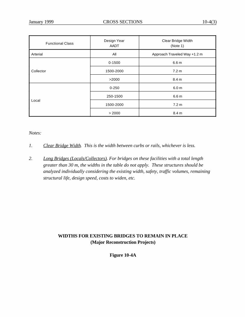
January 1999 CROSS SECTIONS 10-4(3)
Functional ClassDesign Year
AADTClear Bridge Width
(Note 1)
Arterial All Approach Traveled Way +1.2 m
Collector
0-1500 6.6 m
1500-2000 7.2 m
>2000 8.4 m
Local
0-250 6.0 m
250-1500 6.6 m
1500-2000 7.2 m
> 2000 8.4 m
Notes:
1. Clear Bridge Width. This is the width between curbs or rails, whichever is less.
2. Long Bridges (Locals/Collectors). For bridges on these facilities with a total lengthgreater than 30 m, the widths in the table do not apply. These structures should beanalyzed individually considering the existing width, safety, traffic volumes, remainingstructural life, design speed, costs to widen, etc.
WIDTHS FOR EXISTING BRIDGES TO REMAIN IN PLACE(Major Reconstruction Projects)
Figure 10-4A

10-4(4) CROSS SECTIONS January 1999
January 1999 CROSS SECTIONS 10-5(1)
10-5.0 RIGHT-OF-WAY
For information on the types of right-of-ways (e.g., permanent, temporary, easements), the designer shouldreview the Department's Policies and Procedures for Property Maps. The right-of-way width shouldbe sufficiently wide to provide the selected cross section elements and dimensions, to provide properdrainage, to allow maintenance of the facility and to provide for future expansion of the cross section.However, restrictions along the highway corridor may require some compromises in determining the ROWwidth. In these cases, the selected highway cross section may be limited by the available ROW.
The following summarizes the Department's criteria for determining the ROW width:
1. Freeways (All Projects). The upper range of the ROW width should be the sum of the travel laneand median width plus 30 m beyond the edge of the outside travel lane on each side or side sloperequirements, whichever governs. In urban areas, the minimum ROW width will be the sum of thetravel lane and median widths plus the roadside clear zone on each side or side slope requirements,whichever governs.
2. Other Arterials and Collectors (New Construction/Major Reconstruction). The ROW width willbe determined on a project-by-project basis. In determining the ROW width, the designer shouldconsider travel lane widths, median widths, roadside clear zones, utility strips, side sloperequirements, etc.
3. Other Arterials and Collectors (3R Projects). The acquisition of significant amounts of ROW isoften outside the scope of a 3R project. Therefore, the existing ROW will often be unchanged bythe 3R project. However, the designer should, wherever practical, secure additional ROW to allowcost-effective geometric and roadside safety improvements.
4. Local Roads and Streets (All Projects). The ROW width will be as required for the purpose of theproject and will be determined by the local government.
ROW width should be uniform, but this is not a necessity. In urban areas, variable widths may be necessarydue to the existing development; varying side slopes and embankment heights may make it desirable to varyROW width; and, ROW limits will likely have to be adjusted at intersections and freeway interchanges.The following special ROW controls should also be considered:
1. Sight Distances. At horizontal curves and intersections additional ROW may be warranted toensure that the necessary sight distance is always available in the future.
10-5(2) CROSS SECTIONS January 1999
2. Restricted Areas. In areas where the necessary ROW widths cannot be reasonably obtained, thedesigner should consider using steeper slopes, revising grades, or using slope retaining structures.
3. Railroads. On sections of highway adjacent to railroads, avoid any encroachment on railroadROW whenever feasible.
4. Interchanges. Special ROW considerations at interchanges are discussed in Chapter Twelve.
January 1999 CROSS SECTIONS 10-6(1)
10-6.0 TYPICAL SECTIONS
Chapters Four and Five present several typical section figures for both normal and superelevated sections.The figures are based on:
1. rural or urban location;2. multilane or two-lane;3. type of median (e.g., depressed, raised, with a median barrier); and4. curbed or uncurbed.
In addition, Figure 5M presents a typical section for a high-volume/incident management freeway.“Incident management” refers to events (e.g., accidents) which have the potential to produce majordisruptions to the flow of traffic on a freeway. The critical feature of this typical section is the provision ofa left shoulder with sufficient width to assist in accommodating traffic in the event of a highway incident inthe interim.
The use of this typical section will be determined on a case-by-case basis.

10-6(2) CROSS SECTIONS January 1999
January 1999 CROSS SECTIONS 10-7(1)
10-7.0 REFERENCES
1. A Policy on Geometric Design of Highways and Streets, AASHTO, 1994.
2. Highway Capacity Manual, TRB, 1994.
3. Roadside Design Guide, AASHTO, 1995.
4. TS-80-204, Design of Urban Streets, FHWA, January, 1980.
5. Parking Principles, Special Report No. 125, Highway Research Board, 1971.
6. FHWA-RD-79-75/76, Safety Aspects of Curb Parking, FHWA, 1979.

10-7(2) CROSS SECTIONS January 1999
January 1999 INTERSECTIONS AT-GRADE 11-i
Chapter Eleven
INTERSECTIONS AT-GRADE
Table of Contents
Page
11-1.0 GENERAL DESIGN CONSIDERATIONS . . . . . . . . . . . . . . . . . . . . . . . . . . . 11-1(1)
11-1.01 Capacity . . . . . . . . . . . . . . . . . . . . . . . . . . . . . . . . . . . . . . . . . . . . . 11-1(1)
11-1.01.01 Design Year and Level of Service . . . . . . . . . . . . . . 11-1(1) 11-1.01.02 Capacity Methodology for Signalized Intersections 11-1(1)
11-1.02 Design Vehicle . . . . . . . . . . . . . . . . . . . . . . . . . . . . . . . . . . . . . . . . 11-1(2) 11-1.03 Intersection Alignment . . . . . . . . . . . . . . . . . . . . . . . . . . . . . . . . . . 11-1(2) 11-1.04 Intersection Profile . . . . . . . . . . . . . . . . . . . . . . . . . . . . . . . . . . . . . 11-1(4)
11-1.04.01 Approach Gradient . . . . . . . . . . . . . . . . . . . . . . . . . 11-1(4) 11-1.04.02 Cross Section Transitions . . . . . . . . . . . . . . . . . . . . . 11-1(4)
11-1.05 Intersection Spacing . . . . . . . . . . . . . . . . . . . . . . . . . . . . . . . . . . . . 11-1(6)
11-2.0 INTERSECTION SIGHT DISTANCE (ISD) . . . . . . . . . . . . . . . . . . . . . . . . . . 11-2(1)
11-2.01 Stop-Controlled Intersections . . . . . . . . . . . . . . . . . . . . . . . . . . . . . 11-2(1)
11-2.01.01 Theoretical Discussion (Upper ISD Values) . . . . . . 11-2(1) 11-2.01.02 Theoretical Discussion (Minimum ISD Values) . . . . 11-2(5)
11-2.01.03 ISD Application . . . . . . . . . . . . . . . . . . . . . . . . . . . . 11-2(5) 11-2.01.04 ISD Worksheet . . . . . . . . . . . . . . . . . . . . . . . . . . . . 11-2(8)
11-2.02 Stopped Vehicle Turning Left Across Oncoming Traffic . . . . . . . . 11-2(8) 11-2.03 Signal-Controlled Intersections . . . . . . . . . . . . . . . . . . . . . . . . . . . 11-2(12)
11-3.0 TURNING RADII (Right Turns) . . . . . . . . . . . . . . . . . . . . . . . . . . . . . . . . . . . 11-3(1)
11-3.01 Types of Treatment . . . . . . . . . . . . . . . . . . . . . . . . . . . . . . . . . . . . 11-3(1) 11-3.02 Design Vehicle Selection . . . . . . . . . . . . . . . . . . . . . . . . . . . . . . . . 11-3(1) 11-3.03 Designs for Pavement Edge/Curb Line . . . . . . . . . . . . . . . . . . . . . 11-3(3)
11-3.03.01 Tolerable Encroachment . . . . . . . . . . . . . . . . . . . . . 11-3(5) 11-3.03.02 Inside Clearance . . . . . . . . . . . . . . . . . . . . . . . . . . . 11-3(5)
11-3.03.03 Parking Lanes/Shoulders . . . . . . . . . . . . . . . . . . . . . 11-3(5) 11-3.03.04 Pedestrians . . . . . . . . . . . . . . . . . . . . . . . . . . . . . . . . 11-3(8) 11-3.03.05 Summary . . . . . . . . . . . . . . . . . . . . . . . . . . . . . . . . . 11-3(8)
11-ii INTERSECTIONS AT-GRADE January 1999
Table of Contents(Continued)
Page
11-4.0 TURNING ROADWAYS . . . . . . . . . . . . . . . . . . . . . . . . . . . . . . . . . . . . . . . . 11-4(1)
11-4.01 Guidelines . . . . . . . . . . . . . . . . . . . . . . . . . . . . . . . . . . . . . . . . . . . . 11-4(1) 11-4.02 Design Criteria . . . . . . . . . . . . . . . . . . . . . . . . . . . . . . . . . . . . . . . . 11-4(1)
11-4.02.01 Design Speed . . . . . . . . . . . . . . . . . . . . . . . . . . . . . 11-4(1) 11-4.02.02 Horizontal Alignment . . . . . . . . . . . . . . . . . . . . . . . . 11-4(3) 11-4.02.03 Width . . . . . . . . . . . . . . . . . . . . . . . . . . . . . . . . . . . 11-4(6) 11-4.02.04 Angle of Turn . . . . . . . . . . . . . . . . . . . . . . . . . . . . . 11-4(6) 11-4.02.05 Acceleration/Deceleration Lanes . . . . . . . . . . . . . 11-4(11)
11-5.0 AUXILIARY TURNING LANES . . . . . . . . . . . . . . . . . . . . . . . . . . . . . . . . . 11-5(1)
11-5.01 Guidelines for Right-Turn Lanes . . . . . . . . . . . . . . . . . . . . . . . . . . 11-5(1) 11-5.02 Guidelines for Left-Turn Lanes . . . . . . . . . . . . . . . . . . . . . . . . . . . 11-5(1) 11-5.03 Design Details for Auxiliary Turning Lanes . . . . . . . . . . . . . . . . . . 11-5(8) 11-5.04 Typical Treatments for Auxiliary Turning Lanes . . . . . . . . . . . . . . 11-5(8) 11-5.05 Dual Turn Lanes . . . . . . . . . . . . . . . . . . . . . . . . . . . . . . . . . . . . . . . 11-5(11)11-5.06 Extension of Additional Through Lanes . . . . . . . . . . . . . . . . . . . . 11-5(15)
11-6.0 MEDIAN OPENINGS . . . . . . . . . . . . . . . . . . . . . . . . . . . . . . . . . . . . . . . . . . . 11-6(1)
11-6.01 Guidelines . . . . . . . . . . . . . . . . . . . . . . . . . . . . . . . . . . . . . . . . . . . . 11-6(1) 11-6.02 Design . . . . . . . . . . . . . . . . . . . . . . . . . . . . . . . . . . . . . . . . . . . . . . . 11-6(1) 11-6.03 Median Openings on Freeways . . . . . . . . . . . . . . . . . . . . . . . . . . . 11-6(3)
11-7.0 CHANNELIZATION . . . . . . . . . . . . . . . . . . . . . . . . . . . . . . . . . . . . . . . . . . . . 11-7(1)
11-7.01 Design Principles . . . . . . . . . . . . . . . . . . . . . . . . . . . . . . . . . . . . . . 11-7(1) 11-7.02 Design Details (Islands) . . . . . . . . . . . . . . . . . . . . . . . . . . . . . . . . . 11-7(1)
11-8.0 DRIVEWAYS . . . . . . . . . . . . . . . . . . . . . . . . . . . . . . . . . . . . . . . . . . . . . . . . . 11-8(1)
11-8.01 Design . . . . . . . . . . . . . . . . . . . . . . . . . . . . . . . . . . . . . . . . . . . . . . . 11-8(1)
11-8.01.01 Detailed Criteria . . . . . . . . . . . . . . . . . . . . . . . . . . . 11-8(1) 11-8.01.02 Criteria (Existing Driveways) . . . . . . . . . . . . . . . . . 11-8(6)
11-8.02 Driveway Spacing and Corner Clearances . . . . . . . . . . . . . . . . . . . 11-8(7) 11-8.03 Major Traffic Generators . . . . . . . . . . . . . . . . . . . . . . . . . . . . . . . . 11-8(7)
11-9.0 REFERENCES . . . . . . . . . . . . . . . . . . . . . . . . . . . . . . . . . . . . . . . . . . . . . . . . . 11-9(1)
January 1999 INTERSECTIONS AT-GRADE 11-1(1)
Chapter Eleven
INTERSECTIONS AT-GRADE
11-1.0 GENERAL DESIGN CONSIDERATIONS
11-1.01 Capacity
11-1.01.01 Design Year and Level of Service
To perform the capacity analysis, the designer must select a future design year. For new constructionand major reconstruction, this is typically 20 years from the construction completion date. For 3Rand spot improvement projects, the intersection should be designed to accommodate current trafficvolumes to 10-year future traffic volumes. If the intersection is within the limits of a longer project,the design year for the intersection will be the same as that for the project.
The geometric design tables in Chapters Two, Four and Five present the recommended levels ofservice for highways based on functional classification and urban or rural location. The intersectionlevel of service for the selected design year should meet these criteria so that the highway facilitywill operate at a consistent serviceability. At a minimum, the intersection should operate at no worsethan LOS D.
When a project has experienced a significant delay during design, the designer may be required toperform an updated capacity analysis. The need for this updated analysis will be determined on acase-by-case basis.
11-1.01.02 Capacity Methodology for Signalized Intersections
The Division of Traffic Engineering is responsible for most capacity calculations at intersections. TheDepartment has adopted the unsignalized and signalized intersection methods (Chapters Nine andTen) presented in the Highway Capacity Manual (HCM). For use of other computerized capacityanalysis programs, the designer should contact the Division of Traffic Engineering to determinewhich programs and versions are acceptable to the Department.
11-1(2) INTERSECTIONS AT-GRADE January 1999
11-1.02 Design Vehicle
Designs for right and left turns should accommodate the turning paths of the applicable designvehicle. The detailed design criteria for right turns at intersections are presented in Section 11-3.0.The Department has adopted the following design vehicles for intersection design:
1. P — passenger car2. SU — single unit vehicle (e.g., delivery truck)3. BUS — intercity or city transit bus4. WB-15 — semitrailer truck or tractor-trailer combination with a 12.2-m semitrailer5. WB-19 ("Large" Truck) — tractor with 14.6-m semitrailer.
The turning characteristics of the applicable design vehicle are used to test the adequacy of anexisting or proposed design at an intersection. The designer can determine the amount of vehicularencroachment upon adjacent lanes when making a right turn. This, combined with several otherfactors discussed in Section 11-3.0, will allow the designer to select the appropriate turningtreatment.
11-1.03 Intersection Alignment
All legs of an intersection should be on tangent rather than curved sections. Where a minor roadintersects a major road on a horizontal curve, this complicates the geometric design of theintersection — particularly sight distance, turning movements, channelization and superelevation.If relocation of the intersection is not practical, the designer may be able to realign the minor roadto intersect the major road perpendicular to a tangent at a point on the horizontal curve. Althoughthis is an improvement, this arrangement may still result in difficult turning movements if thesuperelevation is high.
At-grade intersections should intersect at angles between 60o and 90o. (See Figure 11-1A.)Excessively skewed intersections increase the travel distance across the major highway, adverselyaffect sight distance, and complicate the designs for turning movements. If the angle of intersectionis less than 60o, the intersections should be realigned if practical.
The alignment should direct the through vehicle into the appropriate receiving lane across theintersection.
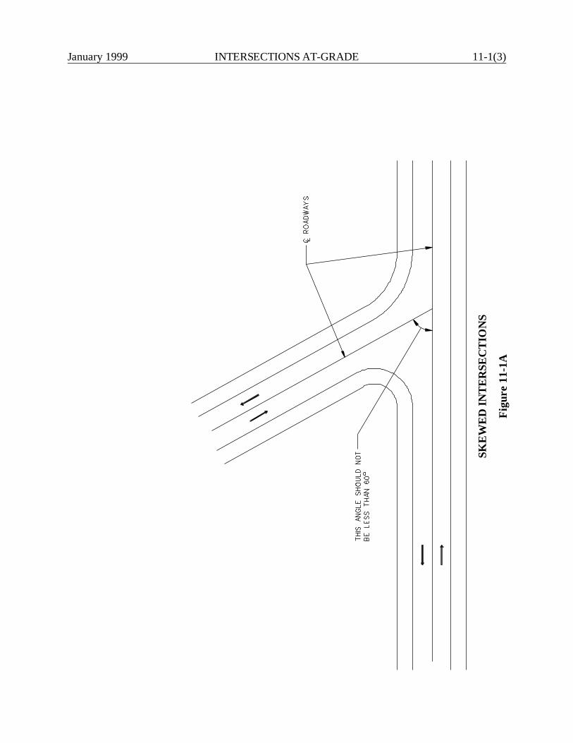
January 1999 INTERSECTIONS AT-GRADE 11-1(3)
SKE
WE
D IN
TE
RSE
CT
ION
S
Figu
re 1
1-1A
11-1(4) INTERSECTIONS AT-GRADE January 1999
11-1.04 Intersection Profile
11-1.04.01 Approach Gradient
The vertical profile of an at-grade intersection should be as level as practical, subject to drainagerequirements. This also applies to the distance along any intersection leg, called the landing area,where vehicles stop waiting to pass through the intersection. Grades approaching or leaving theintersection will affect vehicular deceleration distances (and therefore stopping sight distance) andvehicular acceleration distances. Therefore, the gradient on the landing area should be 3% or less.When designing the profile of a minor road crossing a major highway, the designer should maintainstopping sight distance to the brake lights of the preceding vehicle, approximately 450 mm.
11-1.04.02 Cross Section Transitions
One or more of the approaching legs of the intersection may need to be transitioned (or warped) tomeet the cross section of the two crossing roads. The designer should consider the following:
1. Stop Controlled. When the minor road is stop controlled, the profile and cross section of themajor road will normally be maintained through an intersection, and the cross slope of thestop-controlled leg will be transitioned to match the major road cross slope and profile.
2. Signalized Intersection. At signalized intersections, or potential signalized intersections, thecross section of the minor road will typically be transitioned to meet the profile and crossslope of the major road. If both intersecting roads have approximately equal importance, thedesigner may want to consider transitioning both roadways to form a plane section throughthe intersection. Where compromises are necessary between the two major roadways, thesmoother riding characteristics should be provided for the roadway with the higher trafficvolumes and operating speeds.
3. Transition Rates. Where one or both intersecting roadways are transitioned, the designermust determine the length and rate of transition from the normal section to the modifiedsection; see Figure 11-1B. Consider providing a transition design that meets the generalprinciples of superelevation transition which apply to that roadway (i.e., open-road or low-speed urban street conditions). See Chapter Eight for a complete discussion onsuperelevation development. Where these criteria are applied to transition rates, the applieddesign speed is typically:
a. 50 km/h for a stop-controlled leg,b. the highway design speed for a free-flowing leg, orc. the highway design speed for all legs of a signalized intersection.
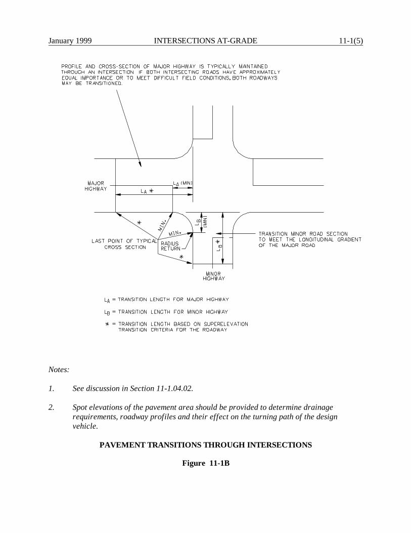
January 1999 INTERSECTIONS AT-GRADE 11-1(5)
Notes:
1. See discussion in Section 11-1.04.02.
2. Spot elevations of the pavement area should be provided to determine drainagerequirements, roadway profiles and their effect on the turning path of the designvehicle.
PAVEMENT TRANSITIONS THROUGH INTERSECTIONS
Figure 11-1B
11-1(6) INTERSECTIONS AT-GRADE January 1999
At a minimum, the approaching legs of an intersection should be transitioned within the curbor curve radius length of the intersection consistent with practical field conditions (see Figure11-1B).
11-1.05 Intersection Spacing
Short distances between intersections should be avoided if practical because they tend to impedetraffic operations. For example, if two intersections are close together and require signalization, theymay need to be considered as one intersection for signalization purposes. To operate safely, each legof the intersection may require a separate green cycle, thereby greatly reducing the capacity for bothintersections. To operate efficiently, signalized intersections should be 400 m apart.
In addition, short gaps between opposing "T" intersections should also be avoided. Drivers tend toencroach into the opposing lanes (corner cutting) so that they can make their turning maneuvers inone movement. In general, all new intersections should preferably be at least 120 m apart.
January 1999 INTERSECTIONS AT-GRADE 11-2(1)
MARCH 2000
11-2.0 INTERSECTION SIGHT DISTANCE (ISD)
11-2.01 Stop-Controlled Intersections
This section presents the Department's ISD criteria for stop-controlled intersections. Where all legsof an intersection are stop controlled, minimum ISD are acceptable. Because of the more difficultmaneuvers at a stop-controlled side road, the use of ISD values in the upper range are encouraged.However, for design exceptions only the minimum values are applicable. A design exception will notbe required where the minimum ISD is not met due to the presence of parked vehicles within theroadway. The presence of permanent objects such as buildings, cut slopes, parking lots, etc., withinthe minimum ISD will require a design exception. The critical maneuvers for ISD are turningmovements either to the left or to the right. The ISD required for crossing movement is less than theleft-turn movement.
11-2.01.01 Theoretical Discussion (Upper ISD Values)
The Department has adopted ISD criteria which differ from those adopted by AASHTO. TheDepartment's upper ISD criteria are based on the Department’s October 1985 report "ParametersAffecting Intersection Sight Distance."
Figure 11-2A illustrates the Department's theoretical assumptions for its upper ISD criteria. The ISDmodel, in summary, assumes that a mainline driver approaches an intersection at design speed as avehicle enters the highway from a side road ahead of the mainline driver. The mainline driver reactsto the vehicle by releasing the accelerator and/or slightly touching the brake. The mainline driverdecelerates at a comfortable rate until a reduced speed, 10% below design speed, is reached. Fromthis point, the mainline driver cruises at the reduced speed until the vehicle is tailgate distance awayfrom the accelerating (entering) vehicle. The entering vehicle is accelerating according to the ratesdeveloped by the Department's research study.
The calculations for the ISD values are based on the following equation:
where: ISD = intersection sight distance, mV = design speed (major road), km/hRV = reduced speed (mainline vehicle), km/hD = deceleration rate (mainline vehicle), km/h/secJ = reaction time (mainline vehicle), secTR = time traveled at reduced speed (mainline vehicle), secXa = distance accelerating (entering) vehicle travels, mTG = tailgate distance, m

11-2(2)IN
TERSEC
TION
S AT-G
RA
DE
January 1999
Notes:
1. See Section 11-2.01.01 for definition of terms.2. ISD for right-turning vehicle is determined in a similar manner.
INTERSECTION SIGHT DISTANCE(Theoretical Model)
Figure 11-2A
January 1999 INTERSECTIONS AT-GRADE 11-2(3)
The theoretical ISD model developed by the Department is intended to find a balance between anacceptable level of safety and what can be practically provided at intersections. The model assignsa reasonable level of responsibility to both the entering vehicle (EV) and mainline vehicle (MV). Thefollowing summarizes the major assumptions within the Department's ISD model:
1. Design Vehicle. The passenger car (P) has been selected for the ISD model.
2. Reaction Time of EV. The model assumes 1 second for the entering driver to release thebrake and depress the accelerator.
3. Acceleration Rate of EV. Based on the Department's research, the ISD model assumes thatthe EV will accelerate at the rates presented in Figure 11-2B. From the acceleration rates,the distance Xa can be determined. These are also provided in Figure 11-2B.
4. Reaction Time of MV (J). This is the time required from the moment the entering vehiclebegins its maneuver until the mainline driver releases the accelerator. These times arepresented in 11-2C. The reaction time of EV (i.e., 1 second) has been added to this value.
5. Deceleration Rate of MV (D). These are based on the Department's field tests as part of theISD research study. The objective was to determine "comfortable" rates of vehiculardeceleration. It was decided to assume deceleration in gear at high speeds and to assumelightly actuating the brakes at low speeds. Deceleration rates are presented in Figure 11-2C.For comparison, the Department's deceleration rates are equal to about 25% of the AASHTO"comfortable" deceleration/braking rates (Figure II-17 of the 1994 Green Book).
6. Reduced Speed of MV (RV). The Department's ISD model assumes that the MV will reduceits speed to 90% of the mainline design speed. Likewise, this is the speed to which the EVwill accelerate to before being overtaken by the MV.
7. Tailgate Distance (TG). This is the distance between the MV and the EV when the EV hasaccelerated to 90% of the design speed on the major road. The TG distance is based onproviding one car length (5.8 m) for each 15 km/h of speed (i.e., 5.8 x RV/15).
8. Eye Location. The ISD values will establish one leg of the sight triangle which needs to bevisible to the EV. The leg on the stop-controlled road or street will be determined by theassumed location of the eye. This is established as 3.0 m to 6.0 m behind the "reference" line.The reference line will normally be the edge of shoulder or curb line. However, it may fallbetween the shoulder edge and travel way edge, if there is reasonable justification to do so.
9. Height of Eye/Object. Both of these values will be 1070 mm.

11-2(4) INTERSECTIONS AT-GRADE January 1999
InitialSpeed(km/h)
FinalSpeed(km/h)
Time(Ta)(sec)
Distance(Xa)(m)
AverageAcceleration
Rate ë(km/h / sec)
00000000
30405060708090100
5.7 8.411.314.517.921.325.028.8
275490138199272359459
5.264.714.424.143.913.763.603.47
Note: ë These criteria are based on field studies reported in Reference 8. Theseare 85th percentile values; i.e., 85% of all cars will accelerate at a fasterrate than in the table.
ISD BASE DATA(Entering Driver)
Figure 11-2B
MainlineDesign Speed(V) (km/h)
ReducedSpeed
(RV) (km/h)
ReactionTime
(J) (sec)
DecelerationRate (D)
(km/h sec)
405060708090100
36455463728190
3.03.64.34.95.56.16.7
1.481.601.731.861.992.132.25
ISD BASE DATA(Mainline Driver)
Figure 11-2C
January 1999 INTERSECTIONS AT-GRADE 11-2(5)
11-2.01.02 Theoretical Discussion (Minimum ISD Values)
The minimum ISD values are developed using the following criteria:
1. the SSD criteria from the AASHTO A Policy on Geometric Design of Highways and Streets;or
2. the SSD criteria from NCHRP 270 Parameters Affecting Stopping Sight Distance (Table27); or
3. the minimum distance for a vehicle to clear the travel lane(s) from the left (minimum ISD tothe left), or the minimum distance for a vehicle to clear the entire intersection (minimum ISDto the right); whichever is larger.
11-2.01.03 ISD Application
The designer will use the criteria in Figure 11-2D and Figure 11-2E to determine the applicable ISDvalues. The designer must make every reasonable effort to meet the values in the upper range of theISD criteria; only for severely restricted locations will the minimum ISD be acceptable. As illustratedin Figure 11-2D, the ISD criteria are based on the distance "X" the turning vehicle must travel fromthe shoulder or curb line to clear the opposing traffic. This allows the application of the Department'sISD model to multilane highways. The designer should also consider the following when determiningthe ISD criteria:
1. The minimum "X" distance will be 6.6 m, even if the actual "X" is less than this value.
2. Each successive column approximately represents an additional lane of opposing traffic (3.6m).
3. The eye location is 3.0 m to 6.0 m behind the reference line. The eye location is independentof "X".
The table assumes that a right-turning vehicle will turn into the outer travel lane in thatdirection. A left-turning vehicle will turn into the inner travel lane in that direction.
5. If the opposing direction of travel includes an exclusive right- or left-turn lane(s) or narrowmedian, these will be included in the "X" distance when reading into the table.
6. For values of "X" which are between columns, the designer should read into the next highestcolumn.
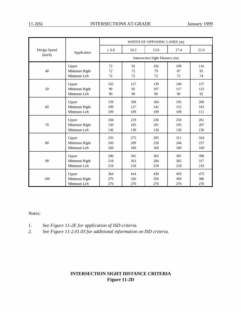
11-2(6) INTERSECTIONS AT-GRADE January 1999
Design Speed(km/h) Application
WIDTH OF OPPOSING LANES (m)
@ 6.6 10.2 13.8 17.4 21.0
Intersection Sight Distance (m)
40UpperMinimum RightMinimum Left
727272
927272
1027972
1098772
1169574
50UpperMinimum RightMinimum Left
1029090
1279590
13910790
14911790
15712592
60UpperMinimum RightMinimum Left
139109109
169127109
184141109
195153109
206163111
70UpperMinimum RightMinimum Left
184130130
219165130
236181130
250195130
261207130
80UpperMinimum RightMinimum Left
235169169
275209169
295228169
311244169
324257169
90UpperMinimum RightMinimum Left
296218218
341263218
363284218
381302218
396317218
100UpperMinimum RightMinimum Left
364276276
414326276
439350276
459369276
475386276
Notes:
1. See Figure 11-2E for application of ISD criteria.2. See Figure 11-2.01.03 for additional information on ISD criteria.
INTERSECTION SIGHT DISTANCE CRITERIAFigure 11-2D
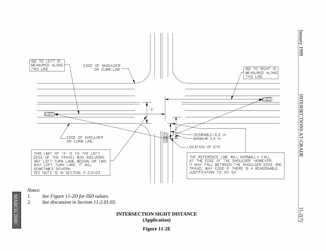
January 1999 IN
TERSEC
TION
S AT-G
RA
DE
11-2(7)
Notes:1. See Figure 11-2D for ISD values.2. See discussion in Section 11-2.01.03.
INTERSECTION SIGHT DISTANCE(Application)
Figure 11-2E
MA
RC
H 2000
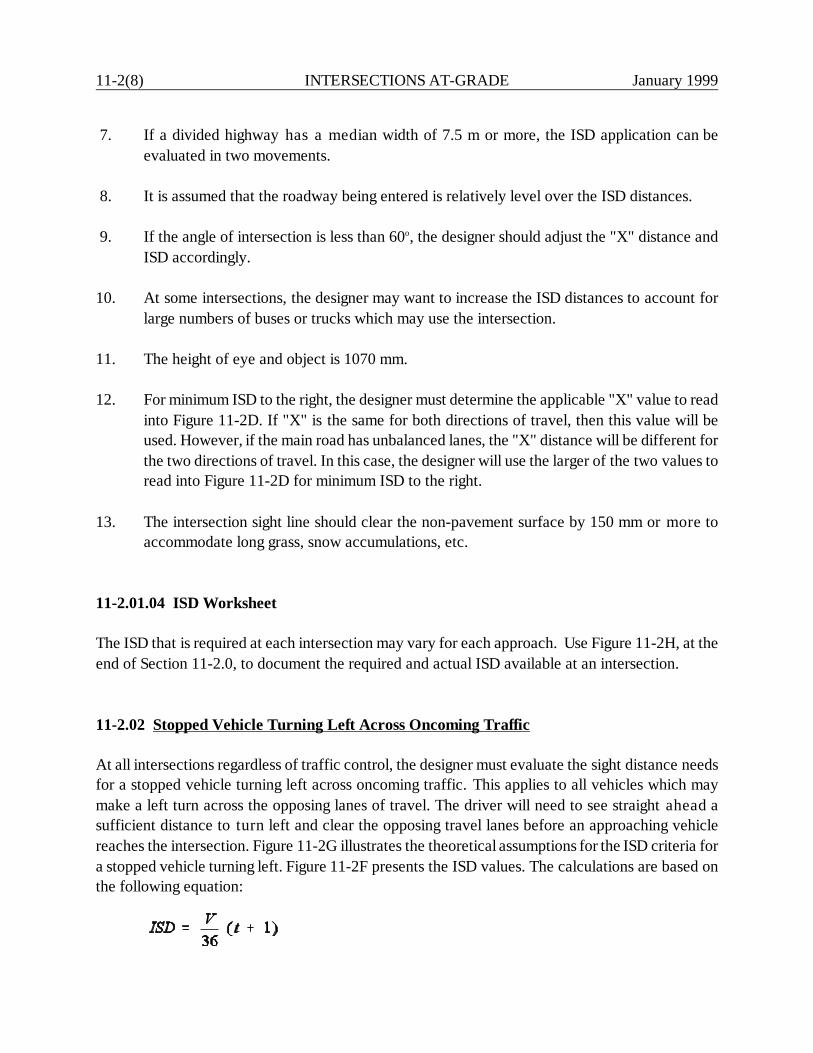
11-2(8) INTERSECTIONS AT-GRADE January 1999
7. If a divided highway has a median width of 7.5 m or more, the ISD application can beevaluated in two movements.
8. It is assumed that the roadway being entered is relatively level over the ISD distances.
9. If the angle of intersection is less than 60o, the designer should adjust the "X" distance andISD accordingly.
10. At some intersections, the designer may want to increase the ISD distances to account forlarge numbers of buses or trucks which may use the intersection.
11. The height of eye and object is 1070 mm.
12. For minimum ISD to the right, the designer must determine the applicable "X" value to readinto Figure 11-2D. If "X" is the same for both directions of travel, then this value will beused. However, if the main road has unbalanced lanes, the "X" distance will be different forthe two directions of travel. In this case, the designer will use the larger of the two values toread into Figure 11-2D for minimum ISD to the right.
13. The intersection sight line should clear the non-pavement surface by 150 mm or more toaccommodate long grass, snow accumulations, etc.
11-2.01.04 ISD Worksheet
The ISD that is required at each intersection may vary for each approach. Use Figure 11-2H, at theend of Section 11-2.0, to document the required and actual ISD available at an intersection.
11-2.02 Stopped Vehicle Turning Left Across Oncoming Traffic
At all intersections regardless of traffic control, the designer must evaluate the sight distance needsfor a stopped vehicle turning left across oncoming traffic. This applies to all vehicles which maymake a left turn across the opposing lanes of travel. The driver will need to see straight ahead asufficient distance to turn left and clear the opposing travel lanes before an approaching vehiclereaches the intersection. Figure 11-2G illustrates the theoretical assumptions for the ISD criteria fora stopped vehicle turning left. Figure 11-2F presents the ISD values. The calculations are based onthe following equation:
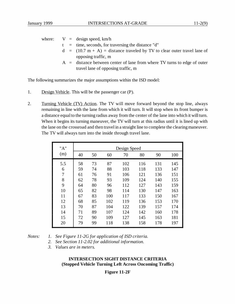
January 1999 INTERSECTIONS AT-GRADE 11-2(9)
where: V = design speed, km/ht = time, seconds, for traversing the distance "d"d = (10.7 m + A) = distance traveled by TV to clear outer travel lane of
opposing traffic, mA = distance between center of lane from where TV turns to edge of outer
travel lane of opposing traffic, m
The following summarizes the major assumptions within the ISD model:
1. Design Vehicle. This will be the passenger car (P).
2. Turning Vehicle (TV) Action. The TV will move forward beyond the stop line, alwaysremaining in line with the lane from which it will turn. It will stop when its front bumper isa distance equal to the turning radius away from the center of the lane into which it will turn.When it begins its turning maneuver, the TV will turn at this radius until it is lined up withthe lane on the crossroad and then travel in a straight line to complete the clearing maneuver.The TV will always turn into the inside through travel lane.
"A"(m)
Design Speed40 50 60 70 80 90 100
5.5 58 73 87 102 116 131 1456 59 74 88 103 118 133 1477 61 76 91 106 121 136 1518 62 78 93 109 124 140 1559 64 80 96 112 127 143 15910 65 82 98 114 130 147 16311 67 83 100 117 133 150 16712 68 85 102 119 136 153 17013 70 87 104 122 139 157 17414 71 89 107 124 142 160 17815 72 90 109 127 145 163 18120 79 99 118 138 158 178 197
Notes: 1. See Figure 11-2G for application of ISD criteria.2. See Section 11-2.02 for additional information.3. Values are in meters.
INTERSECTION SIGHT DISTANCE CRITERIA(Stopped Vehicle Turning Left Across Oncoming Traffic)
Figure 11-2F
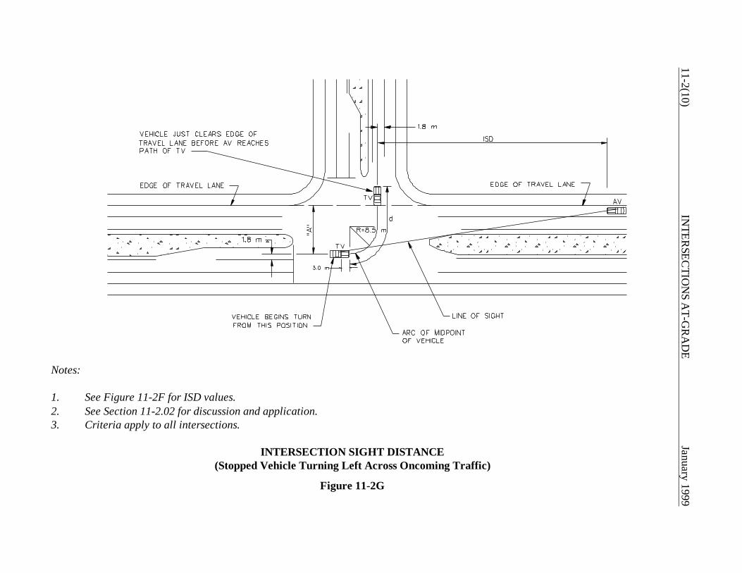
11-2(10)IN
TERSEC
TION
S AT-G
RA
DE
January 1999
Notes:
1. See Figure 11-2F for ISD values.2. See Section 11-2.02 for discussion and application.3. Criteria apply to all intersections.
INTERSECTION SIGHT DISTANCE(Stopped Vehicle Turning Left Across Oncoming Traffic)
Figure 11-2G
January 1999 INTERSECTIONS AT-GRADE 11-2(11)
3. Approaching Vehicle (AV) Action. The AV will travel at the design speed (V) and willmaintain this speed through the intersection (i.e., it will not slow down).
4. Turning Radius. This will be 8.5 m for the mid-section of the TV. This radius will be constantthroughout the turn.
5. Acceleration Rate. The TV will accelerate at the rates found by the Department's field study(Figure 11-2B).
6. Reaction Time of TV. The model assumes one second for the turning driver to release thebrake and depress the accelerator.
7. Clearance Interval. The clearance between the TV and the AV is assumed to be zero.
8. Effect of Median Width. This represents additional distance the TV must traverse. The modelassumes the TV will not move laterally to the left within the intersection area, even if theopportunity is available.
9. Effect of Exclusive Left-Turn Lane. If one is present, the TV will turn from it; if one is notpresent, the TV will turn from the inner through lane. If a dual left-turn lane is present, theTV will turn from the outer left-turn lane, which will yield a greater ISD need.
For application, the ISD criteria for a stopped vehicle turning left will apply to all opportunities forthis maneuver at all intersections. The following procedure should be used:
1. Find the ISD value from Figure 11-2F for the applicable design speed and "A" value at theintersection.
2. Use the ISD value to locate the front bumper of the AV as indicated in Figure 11-2G. Thiswill represent the "object" location.
3. Find the "eye" location as indicated in Figure 11-2G.
4. The line of sight between the eye and object should be clear of all obstacles. The heights ofeye and object are each 1070 mm.

11-2(12) INTERSECTIONS AT-GRADE January 1999
11-2.03 Signal-Controlled Intersections
The minimum ISD requirements in Figure 11-2D will apply to all approach legs to a signalizedintersection.

January 1999 IN
TERSEC
TION
S AT-G
RA
DE
11-2(13)
INTERSECTION SIGHT DISTANCE
Project Number: INTERSECTION:
NAME OF N/SROADWAY
DISTANCE FROMEYE LOCATION
TO NEARESTTHROUGH LANE
APPROACH SPEEDOF CROSSING
TRAFFIC
UPPER ISD(Figure 11-2D)
MINIMUM ISD(Figure 11-2D)
ACTUAL ISDAVAILABLE*
NORTHBOUNDLEFT LANELOOKING LEFTNORTHBOUNDRIGHT LANELOOKING RIGHTSOUTHBOUNDLEFT LANELOOKING LEFTSOUTHBOUNDRIGHT LANELOOKING RIGHTEASTBOUNDLEFT LANELOOKING LEFTEASTBOUNDRIGHT LANELOOKING RIGHTWESTBOUNDLEFT LANELOOKING LEFTWESTBOUNDRIGHT LANELOOKING RIGHT
*A design exception will be required for each location where this is less than the minimum.

11-2(14) INTERSECTIONS AT-GRADE January 1999
January 1999 INTERSECTIONS AT-GRADE 11-3(1)
11-3.0 TURNING RADII (Right Turns)
11-3.01 Types of Treatment
At intersections, the designer must decide how best to accommodate right-turning vehicles. A designmust be selected for the edge of pavement or curb lines, which may be one of the following types:
1. simple radius,2. simple radius with entering and exiting tapers,3. 3-centered symmetric compound curve, or4. 3-centered asymmetric compound curve.
Each basic design type has its advantages and disadvantages. The simple radius is the easiest todesign and construct and, therefore, it is the most common. However, the designer should alsoconsider the benefits of the simple radius with an entering and exiting taper. Its advantages ascompared to other designs include:
1. The simple radius with tapers provides approximately the same transitional benefits as thecompound curvature arrangements, but it is easier to design, survey and construct.
2. To accommodate a specific vehicle with no encroachment, a simple radius requires greaterintersection pavement area than a radius with tapers. For large vehicles, a simple radius isoften an unreasonable design, unless a channelized island is used.
3. A simple radius results in greater distances for pedestrians to cross than a radius with tapers.
4. For angles of turn greater than 90o, a radius with tapers is a better design than a simpleradius, primarily because less intersection area is required.
11-3.02 Design Vehicle Selection
In general, the selected design vehicle should be the largest vehicle likely to make the turn with somefrequency. Therefore, the appropriate design vehicle may vary from intersection to intersection, andthe selection will involve an assessment of the number and types of vehicles which will make theturn. Figure 11-3A presents suggested criteria which the designer should use as a starting point.

11-3(2) INTERSECTIONS AT-GRADE January 1999
For TurnMade From
For TurnMade Onto
Minimum SuggestedDesign Vehicle
TurningRadii (m) (3)
Freeway Ramp All Moving WB-15* 18
ArterialArterial
CollectorLocal
Moving WB-15Moving SUMoving SU
181818
CollectorArterial
CollectorLocal
Moving SUMoving SUMoving SU
181818
LocalArterial
CollectorLocal
Stopped SUStopped SUStopped SU
131313
*WB-19 must be physically able to make the turn.
Notes:
1. The criteria apply to both urban and rural intersections.2. See Section 11-3.02 for a discussion of the selection of a WB-19 truck for intersection
design.3. Radius is for the outer wheel of the turning vehicle.
DESIGN VEHICLE SELECTION
Figure 11-3A

January 1999 INTERSECTIONS AT-GRADE 11-3(3)
The WB-19 design vehicle (large truck) is allowed on the National Truck Network (the Interstatehighway system and other freeways in Connecticut). Large trucks must have reasonable access totruck facilities for a distance of 1.5 km from the Network route. Therefore, large trucks may beallowed to make right turns at some at-grade intersections, and the designer should consider thispossibility. The designer should exercise judgment when deciding which intersections should bedesigned according to the turning characteristics of the large truck. Some intersections (e.g., thosenear truck stops) are obvious candidates. The designer should also consider whether or not anintersection may in the future need to accommodate the large truck. Individuals or entities may applyfor access permits for greater distances through the Commissioner of CONNDOT by applying to theMotor Transport Services Division in the Bureau of Public Transportation. Finally, the designershould consider that even longer trucks than the WB-19 vehicle may today or in the future be nego-tiating the intersection. Where a significant number of these are expected, the designer should takethis into consideration.
11-3.03 Designs for Pavement Edge/Curb Line
Once the designer has selected the design vehicle (Figure 11-3A) and the type of right-turn treatment(e.g., simple radius), he/she must now determine the appropriate design for the pavement edge orcurb line. Figure 11-3B presents recommended criteria. The designer should consider that there arecertain assumptions built into these numbers. The following presents the major assumptions:
1. Encroachment. The criteria in Figure 11-3B will allow the indicated vehicle to make the turnentirely within its lane of travel; i.e., no encroachment into adjacent lanes will occur.
2. Speed. The criteria in Figure 11-3B have been developed assuming a turning speed of lessthan 15 km/h.
3. Inside Clearance. The criteria in the table assumes that a 0.5-m clearance is maintainedthroughout most of the turn and that the clearance is never less than 0.2 m.
4. Parking Lanes/Shoulders. The criteria in the table assume that no parking lanes or shouldersare available which would, of course, allow the vehicle additional space on the inside tomake the turn.
Because of these assumptions, the criteria in Figure 11-3B should serve as a starting point todetermine the design for the pavement edge or curb line. To determine the final design, the designermust use a turning template for the selected design vehicle. The designer should also consider thediscussion in the following sections.
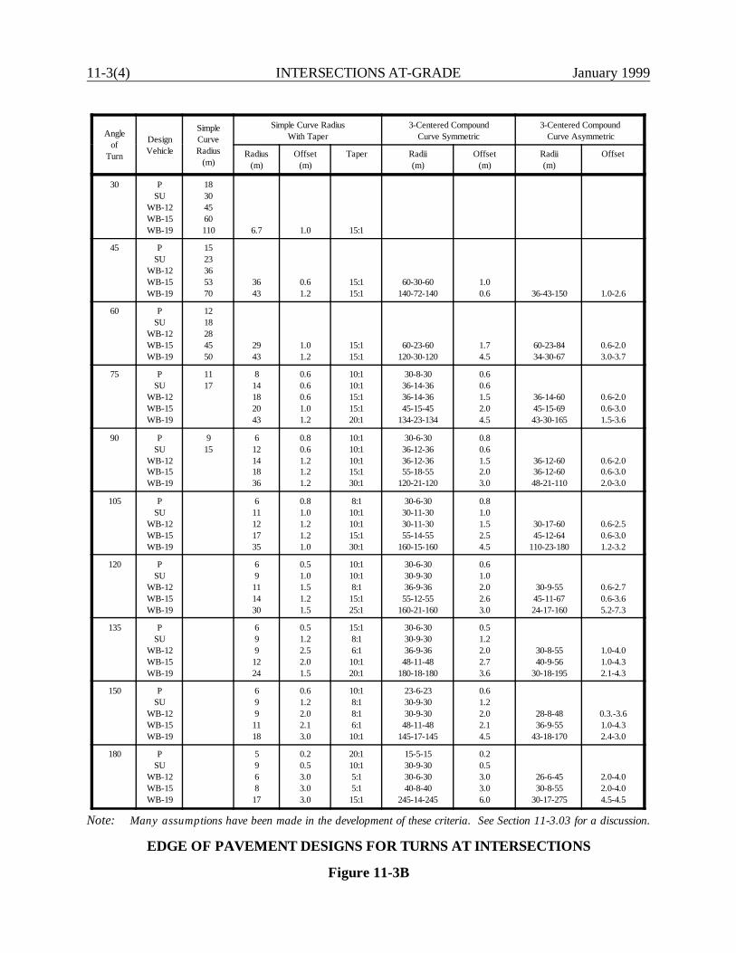
11-3(4) INTERSECTIONS AT-GRADE January 1999
Angleof
Turn
DesignVehicle
SimpleCurveRadius
(m)
Simple Curve RadiusWith Taper
3-Centered CompoundCurve Symmetric
3-Centered Compound Curve Asymmetric
Radius(m)
Offset(m)
Taper Radii(m)
Offset(m)
Radii(m)
Offset
30 PSU
WB-12WB-15WB-19
18304560110 6.7 1.0 15:1
45 PSU
WB-12WB-15WB-19
1523365370
3643
0.61.2
15:115:1
60-30-60140-72-140
1.00.6 36-43-150 1.0-2.6
60 PSU
WB-12WB-15WB-19
1218284550
2943
1.01.2
15:115:1
60-23-60120-30-120
1.74.5
60-23-8434-30-67
0.6-2.03.0-3.7
75 PSU
WB-12WB-15WB-19
1117
814182043
0.60.60.61.01.2
10:110:115:115:120:1
30-8-3036-14-3636-14-3645-15-45
134-23-134
0.60.61.52.04.5
36-14-6045-15-6943-30-165
0.6-2.00.6-3.01.5-3.6
90 PSU
WB-12WB-15WB-19
915
612141836
0.80.61.21.21.2
10:110:110:115:130:1
30-6-3036-12-3636-12-3655-18-55
120-21-120
0.80.61.52.03.0
36-12-6036-12-6048-21-110
0.6-2.00.6-3.02.0-3.0
105 PSU
WB-12WB-15WB-19
611121735
0.81.01.21.21.0
8:110:110:115:130:1
30-6-3030-11-3030-11-3055-14-55
160-15-160
0.81.01.52.54.5
30-17-6045-12-64
110-23-180
0.6-2.50.6-3.01.2-3.2
120 PSU
WB-12WB-15WB-19
69
111430
0.51.01.51.21.5
10:110:18:1
15:125:1
30-6-3030-9-3036-9-36
55-12-55160-21-160
0.61.02.02.63.0
30-9-5545-11-6724-17-160
0.6-2.70.6-3.65.2-7.3
135 PSU
WB-12WB-15WB-19
699
1224
0.51.22.52.01.5
15:18:16:1
10:120:1
30-6-3030-9-3036-9-36
48-11-48180-18-180
0.51.22.02.73.6
30-8-5540-9-56
30-18-195
1.0-4.01.0-4.32.1-4.3
150 PSU
WB-12WB-15WB-19
699
1118
0.61.22.02.13.0
10:18:18:16:1
10:1
23-6-2330-9-3030-9-30
48-11-48145-17-145
0.61.22.02.14.5
28-8-4836-9-55
43-18-170
0.3.-3.61.0-4.32.4-3.0
180 PSU
WB-12WB-15WB-19
5968
17
0.20.53.03.03.0
20:110:15:15:1
15:1
15-5-1530-9-3030-6-3040-8-40
245-14-245
0.20.53.03.06.0
26-6-4530-8-55
30-17-275
2.0-4.02.0-4.04.5-4.5
Note: Many assumptions have been made in the development of these criteria. See Section 11-3.03 for a discussion.
EDGE OF PAVEMENT DESIGNS FOR TURNS AT INTERSECTIONS
Figure 11-3B

January 1999 INTERSECTIONS AT-GRADE 11-3(5)
11-3.03.01 Tolerable Encroachment
To determine the tolerable encroachment, the designer should evaluate several factors, includingtraffic volumes, one-way or two-way operation and the functional classes of the intersecting roadsor streets. Figure 11-3C presents recommended criteria for tolerable encroachment for right-turningvehicles. The designer must evaluate these criteria against the construction and right-of-way impactsfor meeting the encroachment recommendations. For example, if these impacts are significant andif through and/or turning volumes are relatively low, the designer may decide to acceptencroachment for the design vehicle which exceeds the criteria in Figure 11-3C. Considering localconditions, the width of local side road at the back of the curb return should be 9.0 m.
11-3.03.02 Inside Clearance
The following will apply to the assumed inside clearance of the turning vehicle:
1. Maximum. The selected design vehicle will make the right turn while maintaining approximatelya 0.5-m clearance from the pavement edge or curb line and will not come closer than 0.2 m.
2. Minimum. At restricted sites, it may be necessary to assume a less generous clearance. At aminimum, the selected design vehicle may be allowed to make the right turn such that its wheelswill almost touch the pavement edge or curb line. This means that the vehicle will overhangbeyond the edge. Therefore, the designer must ensure that the turning vehicle will not impactany obstructions (e.g., signal poles, mailboxes, signs).
11-3.03.03 Parking Lanes/Shoulders
At many intersections, parking lanes and/or shoulders will be available on one or more approachlegs, and this additional roadway width may be carried through the intersection. This will greatlydecrease the turning problems for large vehicles at intersections with small curb radii. Figure 11-3Dillustrates the turning paths of several design vehicles with curb radii of 4.5 m or 7.5 m and where2.4-m to 3.0-m parking lanes are provided. The presence of a shoulder 2.4 m to 3.0 m in width willhave the same impact as a parking lane. The figure also illustrates the necessary distance to restrictparking before the PC (4.5 m) and after the P.T. (6 m to 12 m) on the cross street. The designer will,of course, need to check the proposed design with the applicable turning template and encroachmentcriteria. The designer should not consider the beneficial effects of a parking lane if the lane will beused for through traffic part of the day or if parking will likely be prohibited in the future.
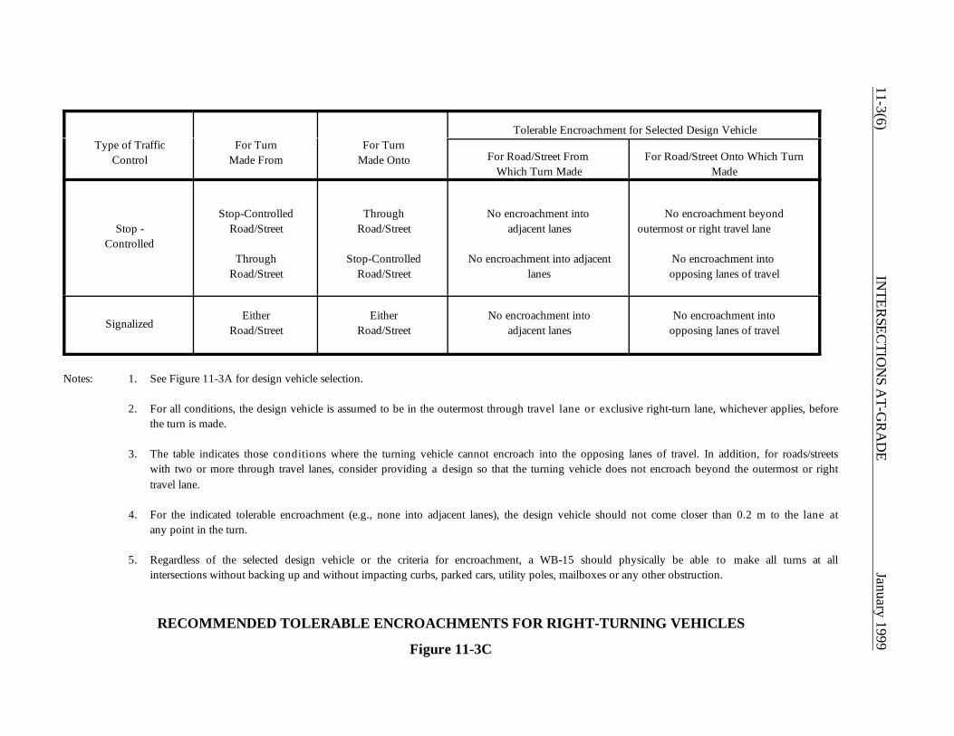
11-3(6)IN
TERSEC
TION
S AT-G
RA
DE
January 1999
Type of TrafficControl
For TurnMade From
For TurnMade Onto
Tolerable Encroachment for Selected Design Vehicle
For Road/Street From Which Turn Made
For Road/Street Onto Which TurnMade
Stop -Controlled
Stop-ControlledRoad/Street
ThroughRoad/Street
ThroughRoad/Street
Stop-ControlledRoad/Street
No encroachment into adjacent lanes
No encroachment into adjacentlanes
No encroachment beyondoutermost or right travel lane
No encroachment into opposing lanes of travel
SignalizedEither
Road/StreetEither
Road/StreetNo encroachment into
adjacent lanesNo encroachment into
opposing lanes of travel
Notes: 1. See Figure 11-3A for design vehicle selection.
2. For all conditions, the design vehicle is assumed to be in the outermost through travel lane or exclusive right-turn lane, whichever applies, beforethe turn is made.
3. The table indicates those conditions where the turning vehicle cannot encroach into the opposing lanes of travel. In addition, for roads/streetswith two or more through travel lanes, consider providing a design so that the turning vehicle does not encroach beyond the outermost or righttravel lane.
4. For the indicated tolerable encroachment (e.g., none into adjacent lanes), the design vehicle should not come closer than 0.2 m to the lane atany point in the turn.
5. Regardless of the selected design vehicle or the criteria for encroachment, a WB-15 should physically be able to make all turns at allintersections without backing up and without impacting curbs, parked cars, utility poles, mailboxes or any other obstruction.
RECOMMENDED TOLERABLE ENCROACHMENTS FOR RIGHT-TURNING VEHICLES
Figure 11-3C
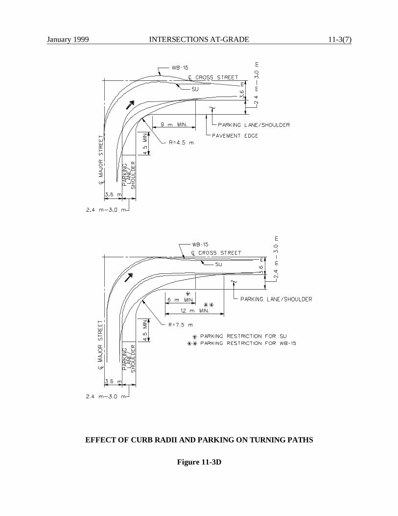
January 1999 INTERSECTIONS AT-GRADE 11-3(7)
EFFECT OF CURB RADII AND PARKING ON TURNING PATHS
Figure 11-3D
11-3(8) INTERSECTIONS AT-GRADE January 1999
11-3.03.04 Pedestrians
The greater the turning radius or the number of lanes, the farther pedestrians must walk in theroadway. This is especially important to handicapped individuals. Therefore, the designer shouldconsider this when determining the edge of pavement or curb line design. This may lead to, forexample, the decision to use a turning roadway (see Section 11-4.0) to provide a pedestrian refuge.In addition, where the pedestrian must cross more than four lanes, the designer should evaluate theaccommodation of pedestrian traffic.
11-3.03.05 Summary
In summary, the designer should determine the proper design for the edge of pavement or curb lineto accommodate right-turning vehicles as follows:
1. Select the type of turning treatment:
a. simple radius,b. simple radius with entering and exiting tapers,c. 3-centered symmetric compound curve, ord. 3-centered asymmetric compound curve.
Use Figure 11-3B as a starting point.
2. Select the design vehicle (Figure 11-3A).
3. Determine the tolerable encroachment (Figure 11-3C).
4. Determine the appropriate inside clearance (Section 11-3.03.02).
5. Consider the benefits of any parking lanes or shoulders (Section 11-3.03.03).
6. Consider impacts on pedestrians (Section 11-3.03.04).
7. Check all proposed designs with the applicable vehicular turning template.
8. Revise design as necessary to accommodate the right-turning vehicle or determine that thisis not practical because of adverse impacts.
January 1999 INTERSECTIONS AT-GRADE 11-4(1)
11-4.0 TURNING ROADWAYS
Turning roadways are channelized areas (painted or raised) at intersections at-grade.
11-4.01 Guidelines
The need for a turning roadway will be determined on a case-by-case basis. The designer shouldconsider using turning roadways when:
1. there is a need to allow right turns at 25 km/h or more on, for example, rural or urbanarterials;
2. the angle of turn will be greater than 90o;
3. the volume of right turns is especially high;
4. there is significant amount of unused pavement; and/or
5. the selected design vehicle is a semi-trailer combination.
11-4.02 Design Criteria
Figure 11-4A illustrates a typical design for a turning roadway at an urban intersection. Thefollowing sections provide additional guidance on the design of a turning roadway.
11-4.02.01 Design Speed
Where practical, the design speed on a turning roadway should be within 30 km/h of the mainlinedesign speed. However, a turning roadway even at a low design speed (e.g., 20 km/h) will stillprovide a significant benefit to the turning vehicle regardless of the speed on the approachinghighway. Typically, the design speed for a turning roadway will be in the range of 20-30 km/h. For3-centered compound curves, this criteria applies to the design speed of the sharpest curve.
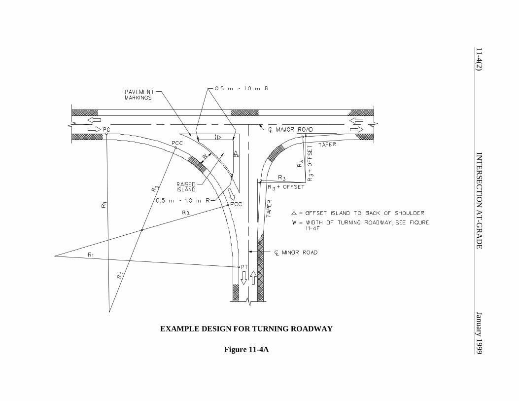
11-4(2)IN
TERSEC
TION
AT-G
RA
DE
January 1999
EXAMPLE DESIGN FOR TURNING ROADWAY
Figure 11-4A
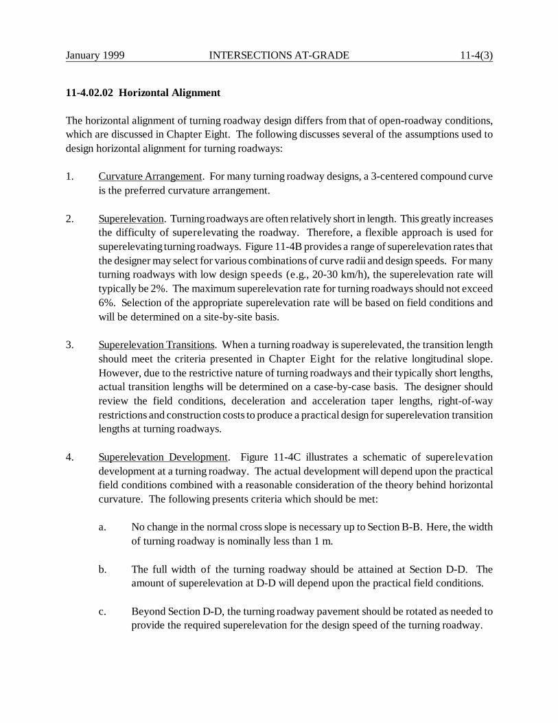
January 1999 INTERSECTIONS AT-GRADE 11-4(3)
11-4.02.02 Horizontal Alignment
The horizontal alignment of turning roadway design differs from that of open-roadway conditions,which are discussed in Chapter Eight. The following discusses several of the assumptions used todesign horizontal alignment for turning roadways:
1. Curvature Arrangement. For many turning roadway designs, a 3-centered compound curveis the preferred curvature arrangement.
2. Superelevation. Turning roadways are often relatively short in length. This greatly increasesthe difficulty of superelevating the roadway. Therefore, a flexible approach is used forsuperelevating turning roadways. Figure 11-4B provides a range of superelevation rates thatthe designer may select for various combinations of curve radii and design speeds. For manyturning roadways with low design speeds (e.g., 20-30 km/h), the superelevation rate willtypically be 2%. The maximum superelevation rate for turning roadways should not exceed6%. Selection of the appropriate superelevation rate will be based on field conditions andwill be determined on a site-by-site basis.
3. Superelevation Transitions. When a turning roadway is superelevated, the transition lengthshould meet the criteria presented in Chapter Eight for the relative longitudinal slope.However, due to the restrictive nature of turning roadways and their typically short lengths,actual transition lengths will be determined on a case-by-case basis. The designer shouldreview the field conditions, deceleration and acceleration taper lengths, right-of-wayrestrictions and construction costs to produce a practical design for superelevation transitionlengths at turning roadways.
4. Superelevation Development. Figure 11-4C illustrates a schematic of superelevationdevelopment at a turning roadway. The actual development will depend upon the practicalfield conditions combined with a reasonable consideration of the theory behind horizontalcurvature. The following presents criteria which should be met:
a. No change in the normal cross slope is necessary up to Section B-B. Here, the widthof turning roadway is nominally less than 1 m.
b. The full width of the turning roadway should be attained at Section D-D. Theamount of superelevation at D-D will depend upon the practical field conditions.
c. Beyond Section D-D, the turning roadway pavement should be rotated as needed toprovide the required superelevation for the design speed of the turning roadway.
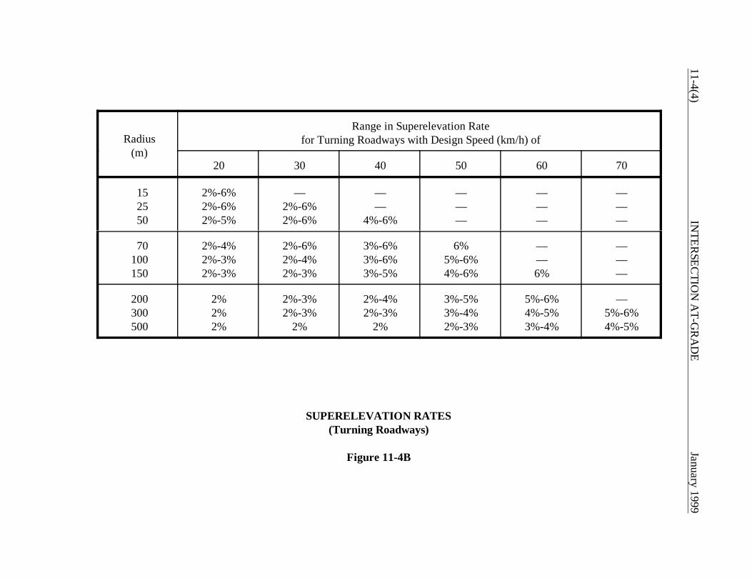
11-4(4)IN
TERSEC
TION
AT-G
RA
DE
January 1999
Radius(m)
Range in Superelevation Ratefor Turning Roadways with Design Speed (km/h) of
20 30 40 50 60 70
152550
2%-6%2%-6%2%-5%
—2%-6%2%-6%
——
4%-6%
———
———
———
70100150
2%-4%2%-3%2%-3%
2%-6%2%-4%2%-3%
3%-6%3%-6%3%-5%
6%5%-6%4%-6%
——6%
———
200300500
2%2%2%
2%-3%2%-3%
2%
2%-4%2%-3%
2%
3%-5%3%-4%2%-3%
5%-6%4%-5%3%-4%
—5%-6%4%-5%
SUPERELEVATION RATES(Turning Roadways)
Figure 11-4B

January 1999 INTERSECTIONS AT-GRADE 11-4(5)
Note: The axis of rotation is first about Edge 2 and then about Edge 4.
DEVELOPMENT OF SUPERELEVATION ATTURNING ROADWAY TERMINALS
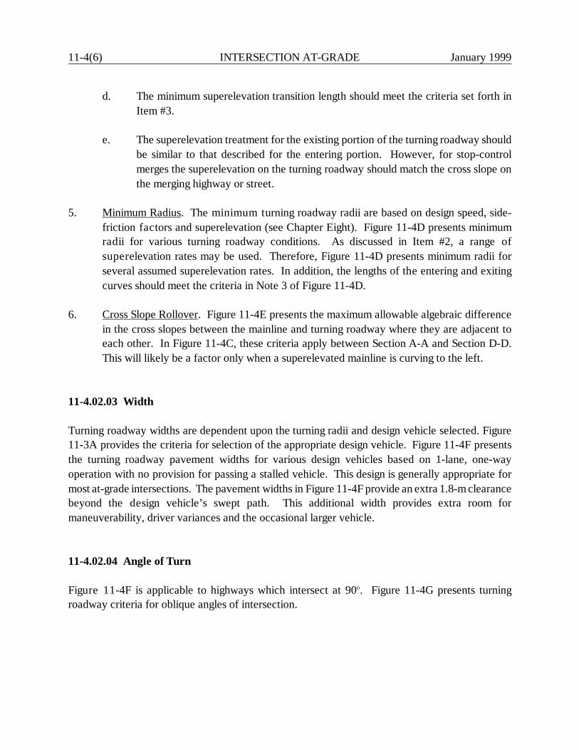
11-4(6) INTERSECTION AT-GRADE January 1999
d. The minimum superelevation transition length should meet the criteria set forth inItem #3.
e. The superelevation treatment for the existing portion of the turning roadway shouldbe similar to that described for the entering portion. However, for stop-controlmerges the superelevation on the turning roadway should match the cross slope onthe merging highway or street.
5. Minimum Radius. The minimum turning roadway radii are based on design speed, side-friction factors and superelevation (see Chapter Eight). Figure 11-4D presents minimumradii for various turning roadway conditions. As discussed in Item #2, a range ofsuperelevation rates may be used. Therefore, Figure 11-4D presents minimum radii forseveral assumed superelevation rates. In addition, the lengths of the entering and exitingcurves should meet the criteria in Note 3 of Figure 11-4D.
6. Cross Slope Rollover. Figure 11-4E presents the maximum allowable algebraic differencein the cross slopes between the mainline and turning roadway where they are adjacent toeach other. In Figure 11-4C, these criteria apply between Section A-A and Section D-D.This will likely be a factor only when a superelevated mainline is curving to the left.
11-4.02.03 Width
Turning roadway widths are dependent upon the turning radii and design vehicle selected. Figure11-3A provides the criteria for selection of the appropriate design vehicle. Figure 11-4F presentsthe turning roadway pavement widths for various design vehicles based on 1-lane, one-wayoperation with no provision for passing a stalled vehicle. This design is generally appropriate formost at-grade intersections. The pavement widths in Figure 11-4F provide an extra 1.8-m clearancebeyond the design vehicle’s swept path. This additional width provides extra room formaneuverability, driver variances and the occasional larger vehicle.
11-4.02.04 Angle of Turn
Figure 11-4F is applicable to highways which intersect at 90o. Figure 11-4G presents turningroadway criteria for oblique angles of intersection.
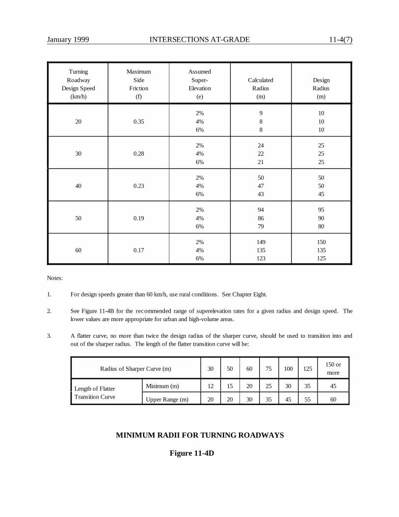
January 1999 INTERSECTIONS AT-GRADE 11-4(7)
TurningRoadway
Design Speed(km/h)
MaximumSide
Friction(f)
AssumedSuper-
Elevation(e)
CalculatedRadius
(m)
DesignRadius
(m)
20 0.352%4%6%
988
101010
30 0.282%4%6%
242221
252525
40 0.232%4%6%
504743
505045
50 0.192%4%6%
948679
959080
60 0.172%4%6%
149135123
150135125
Notes:
1. For design speeds greater than 60 km/h, use rural conditions. See Chapter Eight.
2. See Figure 11-4B for the recommended range of superelevation rates for a given radius and design speed. Thelower values are more appropriate for urban and high-volume areas.
3. A flatter curve, no more than twice the design radius of the sharper curve, should be used to transition into andout of the sharper radius. The length of the flatter transition curve will be:
Radius of Sharper Curve (m) 30 50 60 75 100 125150 ormore
Length of FlatterTransition Curve
Minimum (m) 12 15 20 25 30 35 45
Upper Range (m) 20 20 30 35 45 55 60
MINIMUM RADII FOR TURNING ROADWAYS
Figure 11-4D
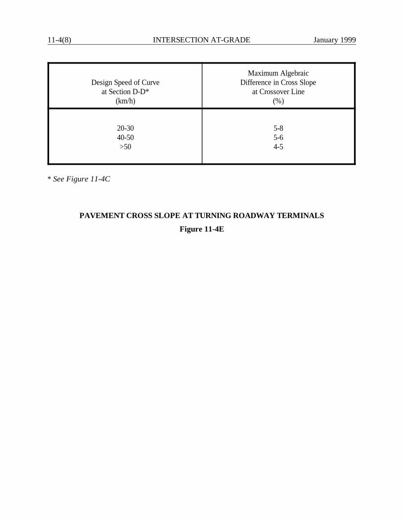
11-4(8) INTERSECTION AT-GRADE January 1999
Design Speed of Curveat Section D-D*
(km/h)
Maximum AlgebraicDifference in Cross Slope
at Crossover Line(%)
20-3040-50>50
5-85-64-5
* See Figure 11-4C
PAVEMENT CROSS SLOPE AT TURNING ROADWAY TERMINALS
Figure 11-4E

January 1999 IN
TERSEC
TION
S AT-G
RA
DE
11-4(9)
Radius on InnerEdge of Pavement,
R(m)
Width of Turning Roadways (m)
P SU WB-15 WB-19
152530
3.93.93.9
5.45.14.8
7.86.66.3
7.87.56.9
5075
100
3.63.63.6
4.84.84.5
5.75.15.1
6.35.75.4
125150
Tangent
3.63.63.6
4.54.54.5
4.84.84.8
5.15.14.5
Notes:
1. If barrier curb is used on one side, then a curb offset of 0.3 m should be added to the table value.
2. If barrier curb is used on both sides, then a curb offset of 0.6 m (0.3 m on each side) should be added to the table value.
PAVEMENT WIDTHS FOR TURNING ROADWAYS
Figure 11-4F
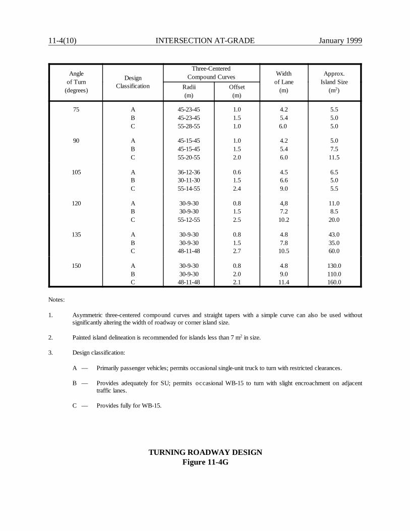
11-4(10) INTERSECTION AT-GRADE January 1999
Angleof Turn
(degrees)
DesignClassification
Three-CenteredCompound Curves Width
of Lane(m)
Approx.Island Size
(m2)Radii(m)
Offset(m)
75 ABC
45-23-4545-23-4555-28-55
1.01.51.0
4.25.46.0
5.55.05.0
90 ABC
45-15-4545-15-4555-20-55
1.01.52.0
4.25.46.0
5.07.5
11.5
105 ABC
36-12-3630-11-3055-14-55
0.61.52.4
4.56.69.0
6.55.05.5
120 ABC
30-9-3030-9-30
55-12-55
0.81.52.5
4,87.2
10.2
11.08.5
20.0
135 ABC
30-9-3030-9-30
48-11-48
0.81.52.7
4.87.8
10.5
43.035.060.0
150 ABC
30-9-3030-9-30
48-11-48
0.82.02.1
4.89.0
11.4
130.0110.0160.0
Notes:
1. Asymmetric three-centered compound curves and straight tapers with a simple curve can also be used withoutsignificantly altering the width of roadway or corner island size.
2. Painted island delineation is recommended for islands less than 7 m2 in size.
3. Design classification:
A — Primarily passenger vehicles; permits occasional single-unit truck to turn with restricted clearances.
B — Provides adequately for SU; permits occasional WB-15 to turn with slight encroachment on adjacenttraffic lanes.
C — Provides fully for WB-15.
TURNING ROADWAY DESIGNFigure 11-4G
January 1999 INTERSECTIONS AT-GRADE 11-4(11)
11-4.02.05 Acceleration/Deceleration Lanes
As discussed in Section 11-4.02.01, the design speed on the turning roadway should be within 30km/h of the mainline design speed. Where this is not practical, the designer should consider usinga deceleration lane. They are especially beneficial where mainline and turning volumes are high; atthese intersections, the deceleration lane may also be needed for storage. An acceleration lane forthe exiting portion of the turning roadway may also be justified. However, it may not be used togood advantage if the turning roadway will be stop controlled. Acceleration and deceleration lanesshould be considered at intersections which include turning roadways for arterials with a designspeed of 80 km/h or more. Refer to Section 11-5.0 for the design details of the auxiliary lanes.

11-4(12) INTERSECTION AT-GRADE January 1999
January 1999 INTERSECTIONS AT-GRADE 11-5(1)
11-5.0 AUXILIARY TURNING LANES
This section presents criteria for the design and guidelines for auxiliary lanes at intersections. Inparticular the designer should consider that deceleration lanes are advantageous, especially on high-speed highways. A driver leaving the highway has no choice but to slow down in the through travellane if a deceleration lane is not provided.
11-5.01 Guidelines for Right-Turn Lanes
In general, exclusive right-turn lanes should be provided for at-grade intersections as follows:
1. at any unsignalized intersection on a 2-lane urban or rural highway which satisfies the criteriain Figure 11-5A;
2. at any intersection where a capacity analysis determines a right-turn lane is necessary tomeet the level-of-service criteria; or
3. at any intersection where the accident experience, existing traffic operations, sight distancerestriction or engineering judgment indicates a significant problem related to right-turningvehicles.
11-5.02 Guidelines for Left-Turn Lanes
In general, exclusive left-turn lanes should be provided for at-grade intersections as follows:
1. on all divided urban and rural highways with a median wide enough to allow a left-turn lane(this applies to intersections with public roads and to major traffic generators);
2. for all approaches at arterial/arterial intersections;
3. at any unsignalized intersection on a 2-lane urban or rural highway which satisfies the criteriain Figures 11-5B, 11-5C, 11-5D, 11-5E or 11-5F;
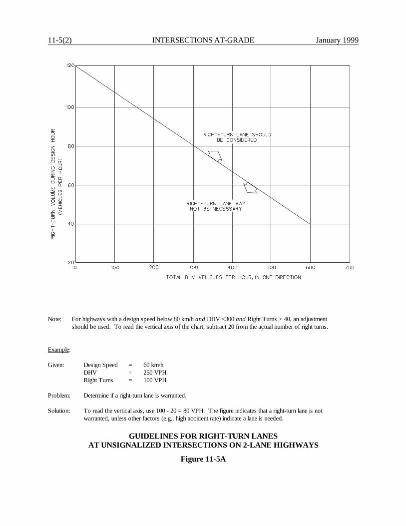
11-5(2) INTERSECTIONS AT-GRADE January 1999
Note: For highways with a design speed below 80 km/h and DHV <300 and Right Turns > 40, an adjustmentshould be used. To read the vertical axis of the chart, subtract 20 from the actual number of right turns.
Example:
Given: Design Speed = 60 km/hDHV = 250 VPHRight Turns = 100 VPH
Problem: Determine if a right-turn lane is warranted.
Solution: To read the vertical axis, use 100 - 20 = 80 VPH. The figure indicates that a right-turn lane is notwarranted, unless other factors (e.g., high accident rate) indicate a lane is needed.
GUIDELINES FOR RIGHT-TURN LANESAT UNSIGNALIZED INTERSECTIONS ON 2-LANE HIGHWAYS
Figure 11-5A
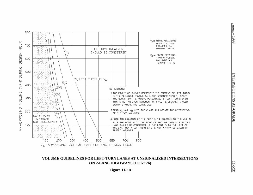
January 1999IN
TERSEC
TION
S AT-G
RA
DE
11-5(3)
VOLUME GUIDELINES FOR LEFT-TURN LANES AT UNSIGNALIZED INTERSECTIONSON 2-LANE HIGHWAYS (100 km/h)
Figure 11-5B

11-5(4)IN
TERSEC
TION
S AT-G
RA
DE
January 1999
VOLUME GUIDELINES FOR LEFT-TURN LANES AT UNSIGNALIZED INTERSECTIONSON 2-LANE HIGHWAYS (90 km/h)
Figure 11-5C
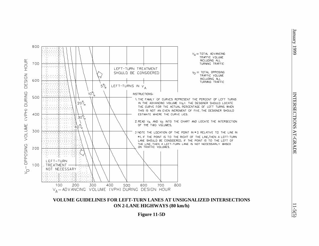
January 1999IN
TERSEC
TION
S AT-G
RA
DE
11-5(5)
VOLUME GUIDELINES FOR LEFT-TURN LANES AT UNSIGNALIZED INTERSECTIONSON 2-LANE HIGHWAYS (80 km/h)
Figure 11-5D
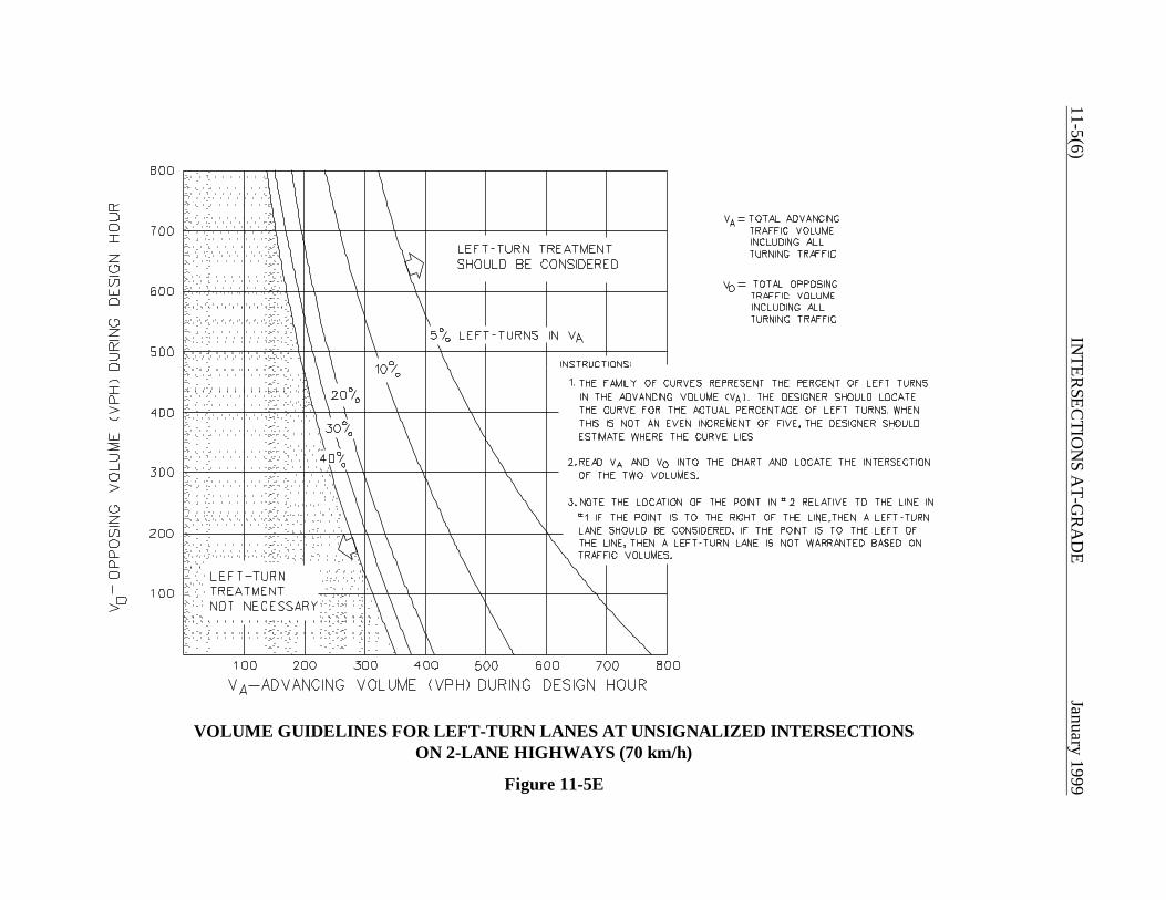
11-5(6)IN
TERSEC
TION
S AT-G
RA
DE
January 1999
VOLUME GUIDELINES FOR LEFT-TURN LANES AT UNSIGNALIZED INTERSECTIONSON 2-LANE HIGHWAYS (70 km/h)
Figure 11-5E
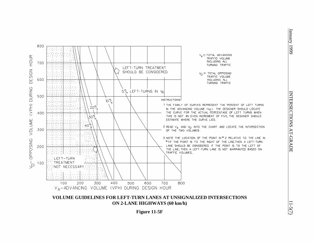
January 1999IN
TERSEC
TION
S AT-G
RA
DE
11-5(7)
VOLUME GUIDELINES FOR LEFT-TURN LANES AT UNSIGNALIZED INTERSECTIONSON 2-LANE HIGHWAYS (60 km/h)
Figure 11-5F
11-5(8) INTERSECTIONS AT-GRADE January 1999
4. at any intersection where a capacity analysis determines a left-turn lane is necessary to meetthe level-of-service criteria;
5. at any intersection included or expected to be within an interconnected signal system wherethe presence of standing left-turning vehicles would disrupt the progression of platoonedtraffic; or
6. at any intersection where the accident experience, traffic operations, sight distancerestrictions or engineering judgment indicates a significant problem related to left-turningvehicles.
11-5.03 Design Details for Auxiliary Turning Lanes
The following criteria will apply to the design of auxiliary turning lanes:
1. Length. The length of a turning lane will be the sum of its taper and storage lengths. Figure11-5G provides the design criteria that should be used to determine these lengths. Thedesigner will coordinate with the Division of Traffic Engineering to determine if additionallength to accommodate deceleration within the auxiliary lane is warranted.
2. Width. The width of the turn lane should be according to the functional class, urban/rurallocation and project scope of work. Chapters Two, Four and Five present the applicablewidths for auxiliary lanes. When curbing is provided, at a minimum, a 0.6-m shoulder shouldbe provided along the turning lane.
3. Parking Lanes. A right-turn lane in an urban area will often require parking restrictionsbeyond the typical restricted distances from the intersection. Also, it may require relocatingnear-side bus stops to the far side of the intersection.
4. Median Openings. These should be designed according to the criteria in Section 11-6.0.
11-5.04 Typical Treatments for Auxiliary Turning Lanes
The following presents typical treatments for right- and left-turn lanes:
1. Right-Turn Lanes. Figure 11-5H illustrates the typical development of an exclusive right-turnlane. Note the insertion of short horizontal curves (R = 15 m) at the beginning and end of thetaper. Consider providing these where curbs define the edge of the turn lane.
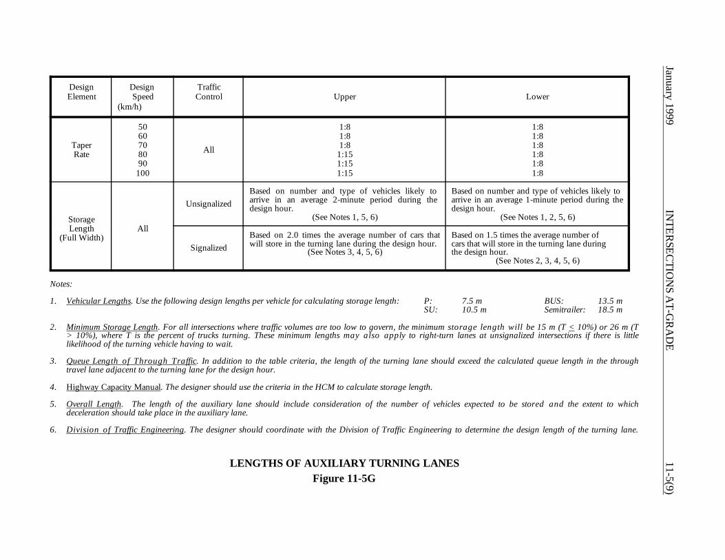
January 1999IN
TERSEC
TION
S AT-G
RA
DE
11-5(9)
DesignElement
Design Speed
(km/h)
TrafficControl Upper Lower
TaperRate
5060708090
100
All
1:81:81:8
1:151:151:15
1:81:81:81:81:81:8
StorageLength
(Full Width)All
UnsignalizedBased on number and type of vehicles likely toarrive in an average 2-minute period during thedesign hour.
(See Notes 1, 5, 6)
Based on number and type of vehicles likely toarrive in an average 1-minute period during thedesign hour.
(See Notes 1, 2, 5, 6)
SignalizedBased on 2.0 times the average number of cars thatwill store in the turning lane during the design hour.
(See Notes 3, 4, 5, 6)
Based on 1.5 times the average number ofcars that will store in the turning lane duringthe design hour.
(See Notes 2, 3, 4, 5, 6)
Notes:
1. Vehicular Lengths. Use the following design lengths per vehicle for calculating storage length: P: 7.5 m BUS: 13.5 mSU: 10.5 m Semitrailer: 18.5 m
2. Minimum Storage Length. For all intersections where traffic volumes are too low to govern, the minimum storage length will be 15 m (T < 10%) or 26 m (T> 10%), where T is the percent of trucks turning. These minimum lengths may also apply to right-turn lanes at unsignalized intersections if there is littlelikelihood of the turning vehicle having to wait.
3. Queue Length of Through Traffic. In addition to the table criteria, the length of the turning lane should exceed the calculated queue length in the throughtravel lane adjacent to the turning lane for the design hour.
4. Highway Capacity Manual. The designer should use the criteria in the HCM to calculate storage length.
5. Overall Length. The length of the auxiliary lane should include consideration of the number of vehicles expected to be stored and the extent to whichdeceleration should take place in the auxiliary lane.
6. Division of Traffic Engineering. The designer should coordinate with the Division of Traffic Engineering to determine the design length of the turning lane.
LENGTHS OF AUXILIARY TURNING LANESFigure 11-5G
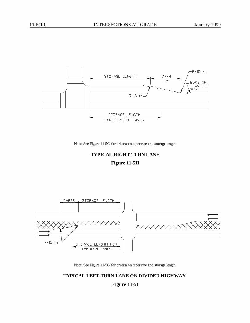
11-5(10) INTERSECTIONS AT-GRADE January 1999
Note: See Figure 11-5G for criteria on taper rate and storage length.
TYPICAL RIGHT-TURN LANE
Figure 11-5H
Note: See Figure 11-5G for criteria on taper rate and storage length.
TYPICAL LEFT-TURN LANE ON DIVIDED HIGHWAY Figure 11-5I
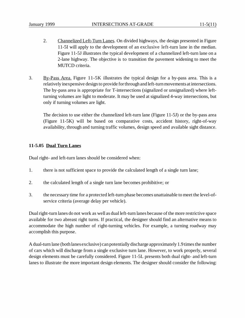
January 1999 INTERSECTIONS AT-GRADE 11-5(11)
2. Channelized Left-Turn Lanes. On divided highways, the design presented in Figure11-5I will apply to the development of an exclusive left-turn lane in the median.Figure 11-5J illustrates the typical development of a channelized left-turn lane on a2-lane highway. The objective is to transition the pavement widening to meet theMUTCD criteria.
3. By-Pass Area. Figure 11-5K illustrates the typical design for a by-pass area. This is arelatively inexpensive design to provide for through and left-turn movements at intersections.The by-pass area is appropriate for T-intersections (signalized or unsignalized) where left-turning volumes are light to moderate. It may be used at signalized 4-way intersections, butonly if turning volumes are light.
The decision to use either the channelized left-turn lane (Figure 11-5J) or the by-pass area(Figure 11-5K) will be based on comparative costs, accident history, right-of-wayavailability, through and turning traffic volumes, design speed and available sight distance.
11-5.05 Dual Turn Lanes
Dual right- and left-turn lanes should be considered when:
1. there is not sufficient space to provide the calculated length of a single turn lane;
2. the calculated length of a single turn lane becomes prohibitive; or
3. the necessary time for a protected left-turn phase becomes unattainable to meet the level-of-service criteria (average delay per vehicle).
Dual right-turn lanes do not work as well as dual left-turn lanes because of the more restrictive spaceavailable for two abreast right turns. If practical, the designer should find an alternative means toaccommodate the high number of right-turning vehicles. For example, a turning roadway mayaccomplish this purpose.
A dual-turn lane (both lanes exclusive) can potentially discharge approximately 1.9 times the numberof cars which will discharge from a single exclusive turn lane. However, to work properly, severaldesign elements must be carefully considered. Figure 11-5L presents both dual right- and left-turnlanes to illustrate the more important design elements. The designer should consider the following:
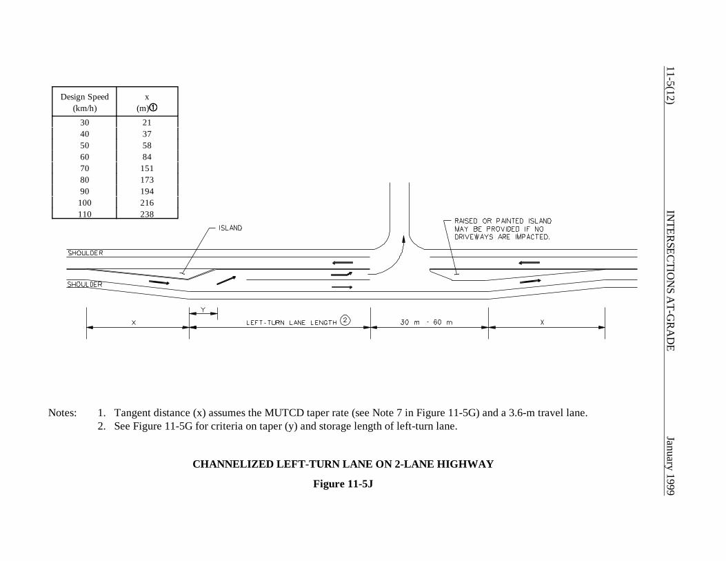
11-5(12)IN
TERSEC
TION
S AT-G
RA
DE
January 1999
Design Speed(km/h)
x(m)ÿÿÿÿ
30 2140 3750 5860 8470 15180 17390 194
100 216110 238
Notes: 1. Tangent distance (x) assumes the MUTCD taper rate (see Note 7 in Figure 11-5G) and a 3.6-m travel lane.2. See Figure 11-5G for criteria on taper (y) and storage length of left-turn lane.
CHANNELIZED LEFT-TURN LANE ON 2-LANE HIGHWAY
Figure 11-5J
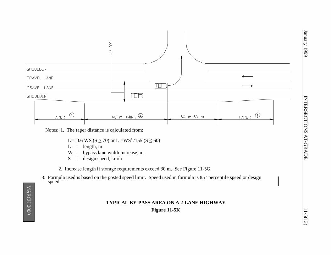
January 1999IN
TERSEC
TION
S AT-G
RA
DE
11-5(13)
MA
RC
H 2000
Notes: 1. The taper distance is calculated from:
L= 0.6 WS (S > 70) or L =WS2 /155 (S < 60)L = length, mW = bypass lane width increase, mS = design speed, km/h
2. Increase length if storage requirements exceed 30 m. See Figure 11-5G.
3. Formula used is based on the posted speed limit. Speed used in formula is 85th percentile speed or design speed
TYPICAL BY-PASS AREA ON A 2-LANE HIGHWAYFigure 11-5K
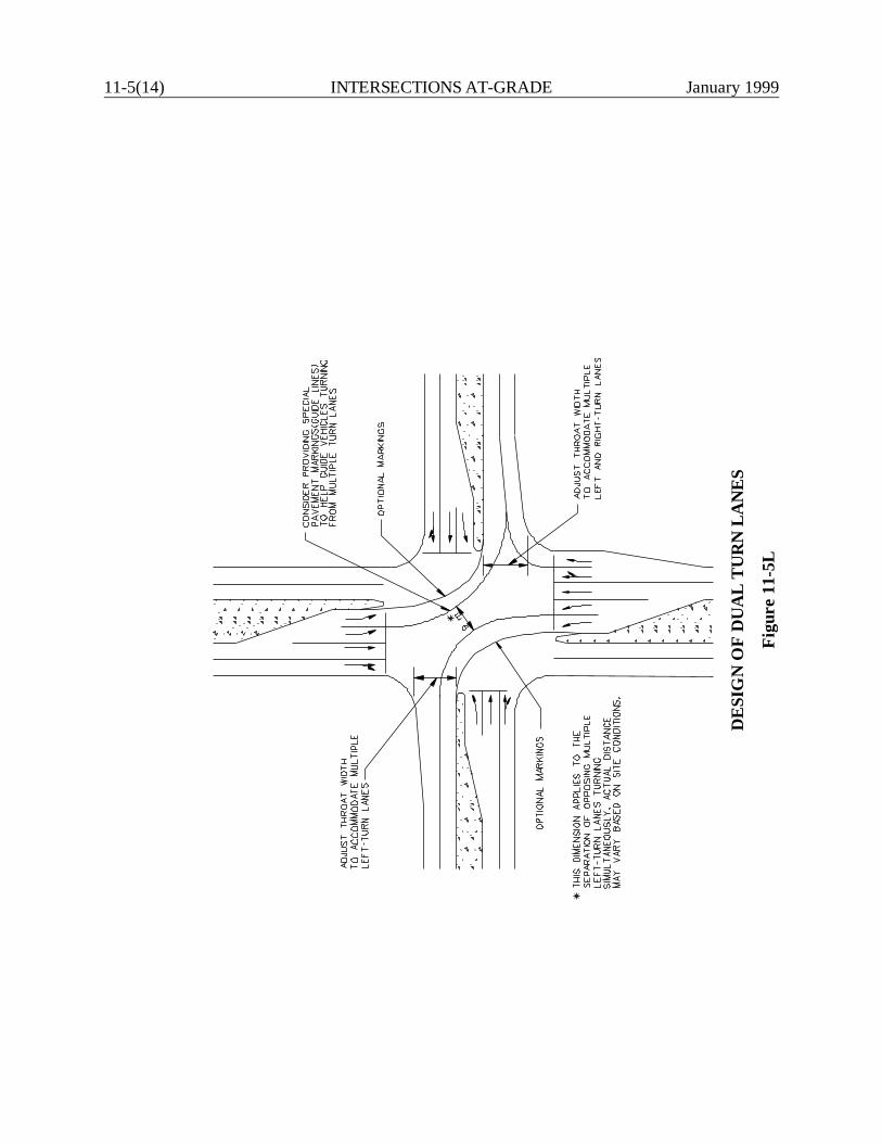
11-5(14) INTERSECTIONS AT-GRADE January 1999
DE
SIG
N O
F D
UA
L T
UR
N L
AN
ES
Figu
re 1
1-5L
January 1999 INTERSECTIONS AT-GRADE 11-5(15)
1. Throat Width. Because of the off-tracking characteristics of turning vehicles, the normalwidth of two travel lanes may be inadequate to properly receive two vehicles turning abreast.Therefore, the receiving throat width may need to be widened. For 90o intersections, thedesigner can expect that the throat width for dual turn lanes will be approximately 9 m to10.8 m. If the angle of turn is less than 90o, it may be acceptable to provide a narrower width.When determining the available throat width, the designer can assume that the pavedshoulder, if present, will be used to accommodate two-abreast turns.
2. Widening Approaching Through Lanes. If a 9-m or 10.8-m throat width is provided toreceive dual-turn lanes, the designer should also consider how this will affect the trafficapproaching from the other side. The designer should also ensure that the through lanes lineup relatively well to ensure a smooth flow of traffic through the intersection.
3. Special Pavement Markings. As illustrated in Figure 11-5L, these can effectively guide twolines of vehicles turning abreast. The Division of Traffic Engineering will help determine theselection and placement of any special pavement markings.
4. Opposing Left-Turn Traffic. If simultaneous, opposing left turns will be allowed, the designershould ensure that there is sufficient space for all turning movements. This is always a factor,but dual left-turn lanes can cause special problems. If space is unavailable, it may benecessary to alter the signal phasing to allow the two directions of traffic to move throughthe intersection on separate phases.
5. Turning Templates. All intersection design elements for dual turn lanes must be checked byusing the applicable turning templates. The design vehicle will be assumed to be in each laneturning side by side.
11-5.06 Extension of Additional Through Lanes
To meet the level-of-service criteria, it may be necessary to add through lanes approaching theintersection. However, these additional lanes must be extended beyond the intersection to realizethe capacity benefits. Figure 11-5M provides criteria for determining how far these lanes should beextended beyond the intersection.
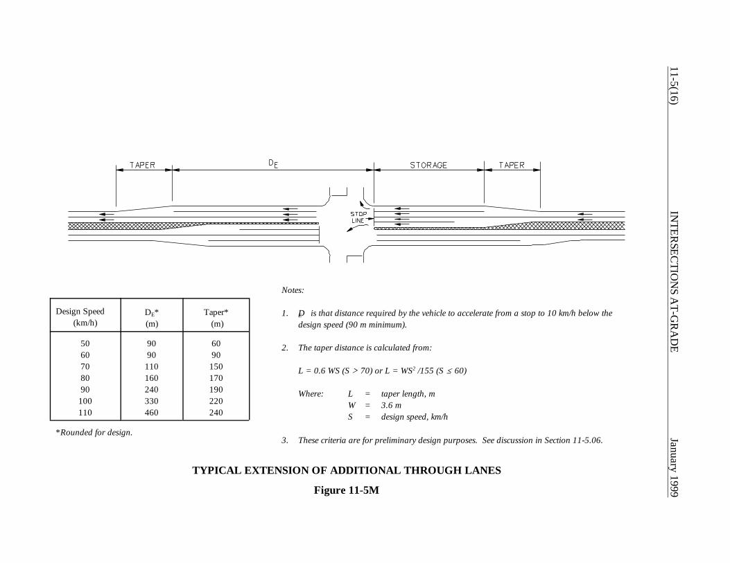
11-5(16)IN
TERSEC
TION
S AT-G
RA
DE
January 1999
Design Speed(km/h)
DE*(m)
Taper* (m)
5060708090
100110
9090
110160240330460
6090
150170190220240
*Rounded for design.
TYPICAL EXTENSION OF ADDITIONAL THROUGH LANES
Figure 11-5M
Notes:
1. DE is that distance required by the vehicle to accelerate from a stop to 10 km/h below thedesign speed (90 m minimum).
2. The taper distance is calculated from:
L = 0.6 WS (S A 70) or L = WS2 /155 (S @ 60)
Where: L = taper length, mW = 3.6 mS = design speed, km/h
3. These criteria are for preliminary design purposes. See discussion in Section 11-5.06.

January 1999 INTERSECTIONS AT-GRADE 11-5(17)
The designer should recognize that the full-width lengths of the through lane extensions (DE) arethose distances needed for the stopped vehicle to accelerate to 10 km/h below the design speed ofthe highway. These distances may or may not be sufficient for the vehicle to merge into the"primary" through lane. The merging characteristics will be based on vehicular acceleration, rate ofdeparture through the intersection and headways in the "primary" lane. Therefore, the criteria inFigure 11-5M should be used for preliminary design purposes. For final design, the designer willcoordinate with the Division of Traffic Engineering, who will perform a more detailed analysis.

11-5(18) INTERSECTIONS AT-GRADE January 1999
January 1999 INTERSECTIONS AT-GRADE 11-6(1)
11-6.0 MEDIAN OPENINGS
11-6.01 Guidelines
The designer should consider providing median openings on divided non-freeways at all intersectionswith public roads and major traffic generators (e.g., shopping centers). The following recommendedminimum spacings should be evaluated when determining the need for a median opening:
1. Rural Intersections. Openings are generally provided at all public road intersections.
2. Urban Intersections. In general, median openings are typically provided at all intersections.However, to improve capacity and traffic efficiency, the designer may elect not to providean opening for a traffic generator if there are other points of access within a reasonabledistance of the generator.
Median openings should normally be between 400 m and 800 m.
11-6.02 Design
Median openings must be designed to properly accommodate left-turning vehicles, which traceessentially the same path as right-turning vehicles. Figure 11-6A illustrates a typical median openingdesign. The following criteria will apply to the design of a median opening:
1. Nose Design. The bullet nose design should be used for the median nose. The radius at thenose should be approximately 0.5 m to 1 m. The semicircular design is acceptable, but itrequires a greater median width or length of opening to accommodate a given design vehicle.
2. Design Vehicle. The design vehicle for median openings should be the largest vehicle thatwill be making the turn with some frequency. The process for the selection of the designvehicle is the same as for a right-turning vehicle (see Section 11-3.02).
3. Encroachment. In all cases, the designer should consider providing a design that will allowthe selected design vehicle to make the left turn entirely within the inside lane (i.e., there willbe no encroachment into the lane adjacent to the inside lane). This will be the minimumdesign at unsignalized intersections. At signalized intersections, the minimum design will beto allow the selected design vehicle to encroach to the outside edge of the traveled way. Fordual left-turn lanes, the designer may assume that the design vehicle will turn from the outerleft-turn lane.
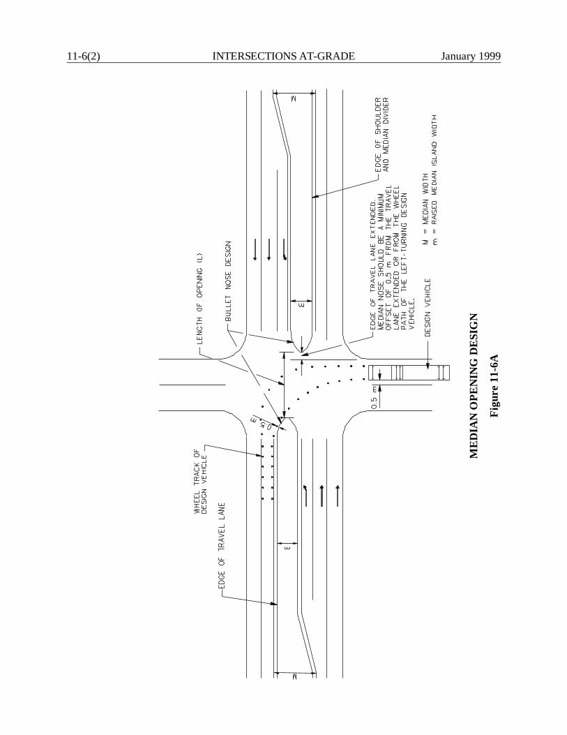
11-6(2) INTERSECTIONS AT-GRADE January 1999
ME
DIA
N O
PEN
ING
DE
SIG
N
Figu
re 1
1-6A
January 1999 INTERSECTIONS AT-GRADE 11-6(3)
4. Length of Opening. The length of a median opening should properly accommodatethe turning path of the design vehicle. The minimum median opening length is 12 m.However, each median opening should be evaluated individually to determine theproper length of opening. The designer should consider the following factors in theevaluation:
a. Turning Templates. The designer should check the proposed design with the turningtemplate for the design vehicle most likely to use the intersection. Considerationshould be given to the frequency of the turn and to the encroachment onto adjacenttravel lanes or shoulders by the turning vehicle.
b. Nose Offset. At 4-leg intersections, traffic passing through the median opening(going straight) will pass the nose and the median end (semicircular or bullet nose).To provide a sense of comfort for these drivers, the offset between the nose and thethrough travel lane (extended) should be at least 0.5 m.
c. Lane Alignment. The designer should ensure that lanes line up properly for crossingtraffic.
d. Location of Crosswalks. Where practical, pedestrian crosswalks should intersect themedian nose to provide some refuge for pedestrians. Therefore, the median openingdesign should be coordinated with the location of crosswalks.
5. U-turns. Median openings are sometimes used only to accommodate U-turns on divided non-freeways. Figure 11-6B provides information on minimum U-turn median opening design.
11-6.03 Median Openings on Freeways
On access-controlled freeways, median crossings are denied to the public. However, occasionalmedian openings or emergency crossovers are needed to accommodate maintenance and emergencyvehicles. The following should be considered:
1. Warrants and Location. Emergency crossovers are normally placed away from any mainlineconflicts. As a general guide, median openings may be considered when the distancebetween interchanges exceeds 5 km. Two crossovers may be considered where the distancebetween interchanges exceed 10 km. In addition, crossovers may be placed at State lines,maintenance section ends and at interchanges for winter maintenance. Locations for medianopenings are reviewed by the Median Opening Committee. This Committee is chaired bythe Director of Maintenance.
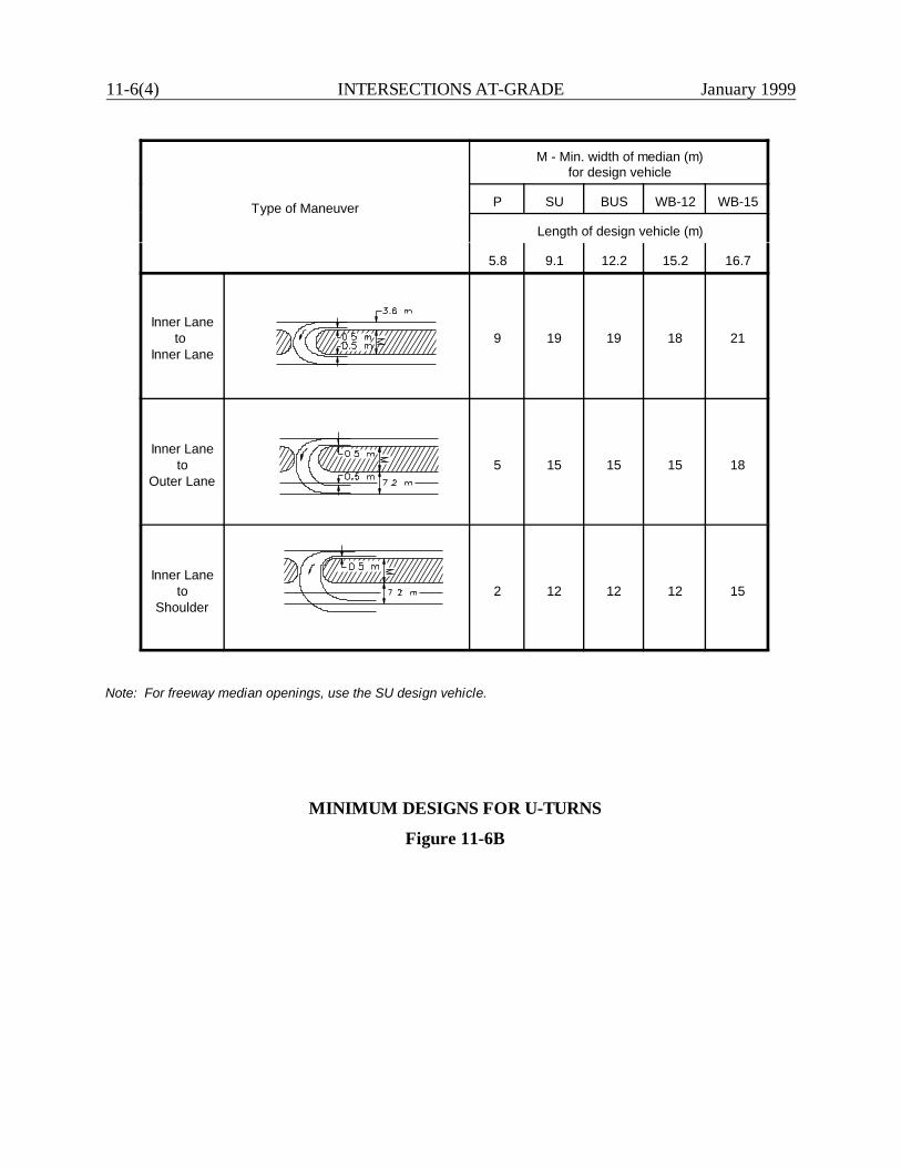
11-6(4) INTERSECTIONS AT-GRADE January 1999
Type of Maneuver
M - Min. width of median (m)for design vehicle
P SU BUS WB-12 WB-15
Length of design vehicle (m)
5.8 9.1 12.2 15.2 16.7
Inner Laneto
Inner Lane9 19 19 18 21
Inner Laneto
Outer Lane5 15 15 15 18
Inner Laneto
Shoulder2 12 12 12 15
Note: For freeway median openings, use the SU design vehicle.
MINIMUM DESIGNS FOR U-TURNS
Figure 11-6B
January 1999 INTERSECTIONS AT-GRADE 11-6(5)
2. Sight Distance. Because of the unexpected U-turn maneuver, sight distances should be largewhen vehicles make U-turns on freeways. The designer should attempt to select a locationthat can achieve a sight distance of 600 m to the right of the crossover in both directions.If this cannot be achieved, then intersection sight distance as discussed in Section 11-2.0 maybe used.
3. Median Width. The median should be wide enough to accommodate the design vehicle.
4. Median Barriers. Emergency crossovers should be avoided where a median barrier is present.If a crossover must be provided, the barrier should be terminated as described in Section13-6.0. The width of the opening should be about 7.5 m to 9.0 m. This is wide enough tosafely allow a vehicle to turn through, but it is narrow enough to minimize the possibility ofa run-off-the-road vehicle passing through.
5. Design. Figure 11-6B provides the minimum width of median for several design vehicles andtypes of U-turn maneuvers. If practical, the design should allow the inner lane to inner lanedesign. This design also allows the vehicle to be fully protected within the median, if thedriver must stop here. Figure 11-6C provides additional design details for a median opening.
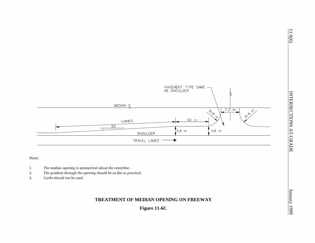
11-6(6)IN
TERSEC
TION
S AT-G
RA
DE
January 1999
Notes:
1. The median opening is symmetrical about the centerline.2. The gradient through the opening should be as flat as practical.3. Curbs should not be used.
TREATMENT OF MEDIAN OPENING ON FREEWAY
Figure 11-6C

January 1999 INTERSECTIONS AT-GRADE 11-6(7)
January 1999 INTERSECTIONS AT-GRADE 11-7(1)
11-7.0 CHANNELIZATION
11-7.01 Design Principles
Intersection channelization directs traffic into definite paths of travel. When properly applied,channelization can increase capacity, improve safety and maximize the sense of driver comfort.Improper channelization can greatly confuse drivers and may be worse than no channelization at all.The designer should incorporate the following principles into the channelization design:
1. Motorists should not be confronted with more than one decision at a time.
2. Unnatural paths that require turns greater than 90o or sudden and sharp reverse curves shouldbe avoided.
3. Areas of vehicular conflict should be reduced as much as practical. However, merging andweaving areas should be as long as conditions permit.
4. Traffic streams that cross without merging and weaving should intersect at or near rightangles.
5. The angle of intersection between merging streams of traffic should be small.
6. Refuge areas for turning vehicles should be provided clear of through traffic.
7. Prohibited turns should be discouraged wherever practical by the use of, for example, sharpradii curbs.
8. Safe location of essential traffic control devices should be an integral part of the design ofa channelized intersection.
11-7.02 Design Details (Islands)
Flush or raised islands are used to create the intersection channelization. The designer should adhereto the following criteria when designing islands:
1. Types. Islands may be flush or raised, paved or turf, and triangular or elongated. Raisedislands (with curbs) should be used where pedestrian traffic is significant and where trafficcontrol devices are needed within the island. The designer should consider lighting theintersection where raised islands are used. Flush (painted) islands are appropriate in lightly
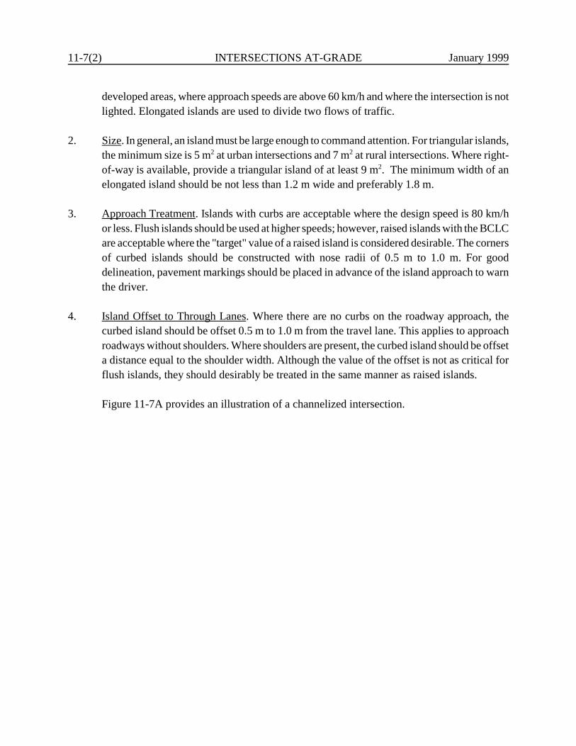
11-7(2) INTERSECTIONS AT-GRADE January 1999
developed areas, where approach speeds are above 60 km/h and where the intersection is notlighted. Elongated islands are used to divide two flows of traffic.
2. Size. In general, an island must be large enough to command attention. For triangular islands,the minimum size is 5 m2 at urban intersections and 7 m2 at rural intersections. Where right-of-way is available, provide a triangular island of at least 9 m2. The minimum width of anelongated island should be not less than 1.2 m wide and preferably 1.8 m.
3. Approach Treatment. Islands with curbs are acceptable where the design speed is 80 km/hor less. Flush islands should be used at higher speeds; however, raised islands with the BCLCare acceptable where the "target" value of a raised island is considered desirable. The cornersof curbed islands should be constructed with nose radii of 0.5 m to 1.0 m. For gooddelineation, pavement markings should be placed in advance of the island approach to warnthe driver.
4. Island Offset to Through Lanes. Where there are no curbs on the roadway approach, thecurbed island should be offset 0.5 m to 1.0 m from the travel lane. This applies to approachroadways without shoulders. Where shoulders are present, the curbed island should be offseta distance equal to the shoulder width. Although the value of the offset is not as critical forflush islands, they should desirably be treated in the same manner as raised islands.
Figure 11-7A provides an illustration of a channelized intersection.

January 1999 INTERSECTIONS AT-GRADE 11-7(3)
Note: Where island size is either less than 6-m wide or 12-m long, it will be paved to minimize maintenance. Otherwise, it will be loamed and seeded. Positive drainage may be required.
EXAMPLE OF CHANNELIZED INTERSECTION
Figure 11-7A

11-7(4) INTERSECTIONS AT-GRADE January 1999

January 1999 INTERSECTIONS AT-GRADE 11-8(1)
11-8.0 DRIVEWAYS
11-8.01 Design
11-8.01.01 Detailed Criteria
Figure 11-8A summarizes the Department's recommended criteria for the design of driveways. Thedesigner should also consider the following:
1. Driveway Type. As indicated in Figure 11-8A, the Department has designated threedriveway types for the purpose of design. These are residential, minor commercial and majorcommercial.
2. Vertical Profile. Figures 11-8B, 11-8C and 11-8D present the Department's drivewayentrance designs for the vertical profile. The designer should meet these criteria, if practical.However, actual field conditions may make this unattainable.
3. Auxiliary Lanes. Deceleration and acceleration lanes should be considered at high-volumedriveway entrances, especially on high-speed, high-volume arterials. Section 11-5.0 furtherdiscusses the design and warrants for auxiliary turn lanes. In addition, it may be warrantedto provide a right-turn lane if the change in grade is abrupt at the driveway entrance.
4. Turning Template. The designer should check the driveway entrance with the applicableturning template to ensure that the design vehicle can make the turn within the drivewaywidth.
5. Sight Distance. Intersection sight distance should be evaluated at all driveways (see Section11-2.0). However, only intersection sight distance for major commercial driveways will beconsidered as a controlling design criteria and will require an exception if the minimumvalues are not met. Residential and minor commercial driveways will not require anexception if the minimum values are not met.
6. Transverse Slopes. Where the highway mainline intersects a driveway, a slope transverse tothe mainline will be present. See Section 13-3.07. If impacted by a run-off-the-road vehicle,the angle of impact will likely be close to 90 degrees. Even for relatively flat side slopes, thiswill result in vehicular vaulting; for steeper slopes the vehicle bumper may "catch" in theslope resulting in an abrupt stop and high occupant decelerations. For these reasons,transverse slopes should be as flat as practical. For design speeds of 80 km/h or higher, theslope should be 1:10 or flatter. Below 80 km/h, the slope should be 1:6 or flatter.
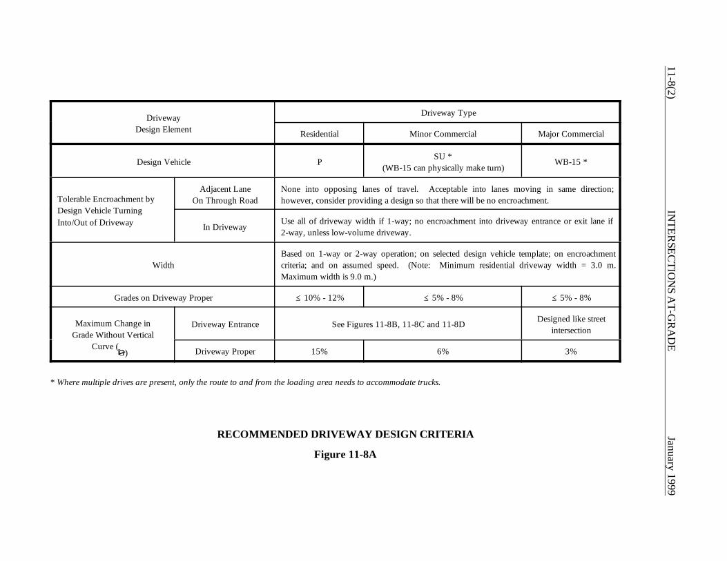
11-8(2)IN
TERSEC
TION
S AT-G
RA
DE
January 1999
DrivewayDesign Element
Driveway Type
Residential Minor Commercial Major Commercial
Design Vehicle P SU *(WB-15 can physically make turn)
WB-15 *
Tolerable Encroachment byDesign Vehicle TurningInto/Out of Driveway
Adjacent LaneOn Through Road
None into opposing lanes of travel. Acceptable into lanes moving in same direction;however, consider providing a design so that there will be no encroachment.
In DrivewayUse all of driveway width if 1-way; no encroachment into driveway entrance or exit lane if2-way, unless low-volume driveway.
WidthBased on 1-way or 2-way operation; on selected design vehicle template; on encroachmentcriteria; and on assumed speed. (Note: Minimum residential driveway width = 3.0 m.Maximum width is 9.0 m.)
Grades on Driveway Proper @ 10% - 12% @ 5% - 8% @ 5% - 8%
Maximum Change inGrade Without Vertical
Curve (F
G)
Driveway Entrance See Figures 11-8B, 11-8C and 11-8D Designed like streetintersection
Driveway Proper 15% 6% 3%
* Where multiple drives are present, only the route to and from the loading area needs to accommodate trucks.
RECOMMENDED DRIVEWAY DESIGN CRITERIA
Figure 11-8A
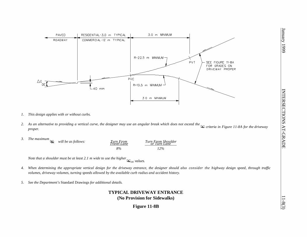
January 1999IN
TERSEC
TION
S AT-G
RA
DE
11-8(3)
1. This design applies with or without curbs.
2. As an alternative to providing a vertical curve, the designer may use an angular break which does not exceed the F
G criteria in Figure 11-8A for the drivewayproper.
3. The maximum F
GDE will be as follows: Turn From Turn From ShoulderTravel Lane or Turn Lane 8% 12%
Note that a shoulder must be at least 2.1 m wide to use the higher F
GDE values.
4. When determining the appropriate vertical design for the driveway entrance, the designer should also consider the highway design speed, through trafficvolumes, driveway volumes, turning speeds allowed by the available curb radius and accident history.
5. See the Department’s Standard Drawings for additional details.
TYPICAL DRIVEWAY ENTRANCE(No Provision for Sidewalks)
Figure 11-8B
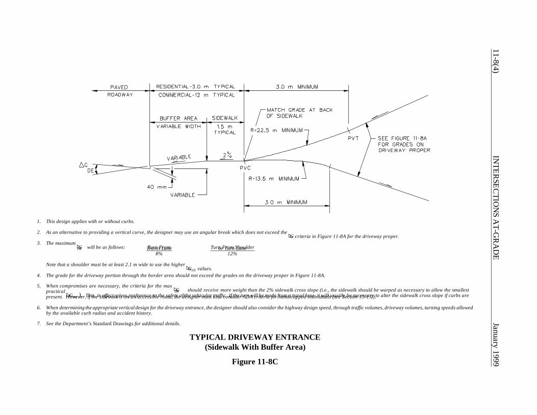
11-8(4)IN
TERSEC
TION
S AT-G
RA
DE
January 1999
1. This design applies with or without curbs.
2. As an alternative to providing a vertical curve, the designer may use an angular break which does not exceed the F
G criteria in Figure 11-8A for the driveway proper.3. The maximum F
GDE will be as follows: Turn From Turn From ShoulderTravel Lane or Turn Lane 8% 12%
Note that a shoulder must be at least 2.1 m wide to use the higher F
GDE values.4. The grade for the driveway portion through the border area should not exceed the grades on the driveway proper in Figure 11-8A.
5. When compromises are necessary, the criteria for the max F
GDE should receive more weight than the 2% sidewalk cross slope (i.e., the sidewalk should be warped as necessary to allow the smallestpractical F
GDE ). This, in effect, gives preference to the safety of the vehicular traffic. If the turn will be made from a travel lane, it will usually be necessary to alter the sidewalk cross slope if curbs arepresent. However, if the sidewalk is on an accessible route, the designer must also consider ADA criteria for handicapped individuals (see Section 15-1.0).
6. When determining the appropriate vertical design for the driveway entrance, the designer should also consider the highway design speed, through traffic volumes, driveway volumes, turning speeds allowedby the available curb radius and accident history.
7. See the Department’s Standard Drawings for additional details.
TYPICAL DRIVEWAY ENTRANCE(Sidewalk With Buffer Area)
Figure 11-8C
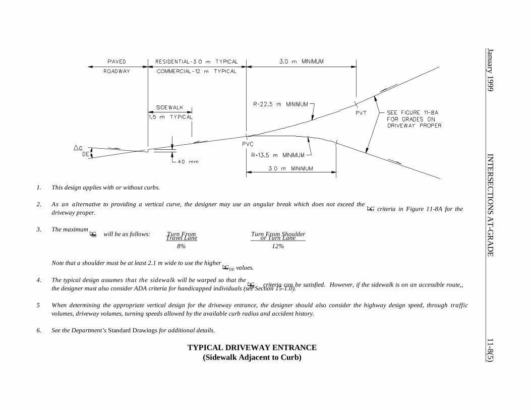
January 1999IN
TERSEC
TION
S AT-G
RA
DE
11-8(5)
1. This design applies with or without curbs.
2. As an alternative to providing a vertical curve, the designer may use an angular break which does not exceed the F
G criteria in Figure 11-8A for thedriveway proper.
3. The maximum F
GDE will be as follows: Turn From Turn From ShoulderTravel Lane or Turn Lane 8% 12%
Note that a shoulder must be at least 2.1 m wide to use the higher F
GDE values.
4. The typical design assumes that the sidewalk will be warped so that the F GDE criteria can be satisfied. However, if the sidewalk is on an accessible route,,the designer must also consider ADA criteria for handicapped individuals (see Section 15-1.0).
5 When determining the appropriate vertical design for the driveway entrance, the designer should also consider the highway design speed, through trafficvolumes, driveway volumes, turning speeds allowed by the available curb radius and accident history.
6. See the Department’s Standard Drawings for additional details.
TYPICAL DRIVEWAY ENTRANCE(Sidewalk Adjacent to Curb)
11-8(6) INTERSECTIONS AT-GRADE January 1999
7. Curb Returns. Where curbs are used, the curb return should be constructed into thedriveway. The radius of the curb return should not be less than 0.6 m nor more than 15 m.
11-8.01.02 Criteria (Existing Driveways)
The following will apply to projects which impact existing driveways:
1. Grades. When an existing driveway is impacted by the project construction, the designershould, whenever practical, ensure that the reconstructed driveway grade will not exceed thegrade of the existing driveway. When the grade must be adjusted, the new grade should notexceed the criteria in Figure 11-8A.
If an existing driveway grade exceeds the criteria in Figure 11-8A, the designer shouldattempt to flatten the grade as part of the project.
2. Procedures. If it is determined during the Preliminary Design review that there will be asubstantial increase in the grade of the driveway or if the length of the driveway will besignificantly revised, then the words, "Right to construct, reconstruct and/or relocatedriveway required," should be noted on the construction plans. This will signify that theproperty owner must be contacted and permission obtained. It will be the responsibility ofthe Right-of-Way representative to contact the property owner to explain the proposedconstruction. This will be done during the acquisition stage of property in the vicinity.
If the proposed reconstruction of a driveway will exceed the Department's driveway designcriteria, alternative solutions will be discussed at the Preliminary Design meeting. Thesesolutions will be presented to the property owner during the regular acquisition of propertyin the vicinity. If neither alternative is acceptable to the owner, the designer may meet withthe Right-of-Way project coordinator for the area concerned to review the driveway design.
3. Project Plans. To ensure a clear understanding of the intended driveway construction and,especially, to depict the treatment of the grade to prevent roadway drainage from flowinginto the property, the normal indication of proposed driveways on 1:500 scale plans andprofiles will be supplemented by a standard sheet, a driveway section or a special detail. Thesection or detail will contain a scale and will be sufficiently detailed so that there will be nomisunderstanding by construction personnel or claim of misrepresentation by the Contractor.
January 1999 INTERSECTIONS AT-GRADE 11-8(7)
11-8.02 Driveway Spacing and Corner Clearances
Closely spaced driveways can cause operational problems, especially with high-volume roadwaysand/or high-volume driveways. These problems can also result if driveways are too close to at-gradeintersections. The following criteria will apply to driveway spacing and corner clearance:
1. Upper Design Values. Figure 11-8E presents criteria which, where practical, should be met.On new construction and major reconstruction projects, the designer should be able toachieve these criteria. This will help provide good traffic operations for the main facility andfor driveways.
2. Minimum. Section 13b-11-15 of the Department's "Highway Encroachment PermitRegulations" discusses criteria for driveway spacing and location. For convenience, Section13b-11-15 is presented at the end of Section 11-8.0. At a minimum, the designer will ensurethat these criteria are met. This will often be applicable on 3R projects. In addition, it will notbe permissible to place any part of a driveway (including its entrance radius) within theradius of a public road at an intersection. If this criteria cannot be met for properties inintersection corners, one possible solution is to relocate the driveway entrance from themajor road to the minor road, if applicable.
11-8.03 Major Traffic Generators
The State Traffic Commission (STC) is responsible for processing and approving access requests formajor traffic generators (e.g., shopping malls). The Department may be requested to review andcomment on the engineering aspects of the access requests. Section 14-311 of the General Statutesprovides the regulatory basis for the authority of the STC to regulate the access of major trafficgenerators onto public roads.
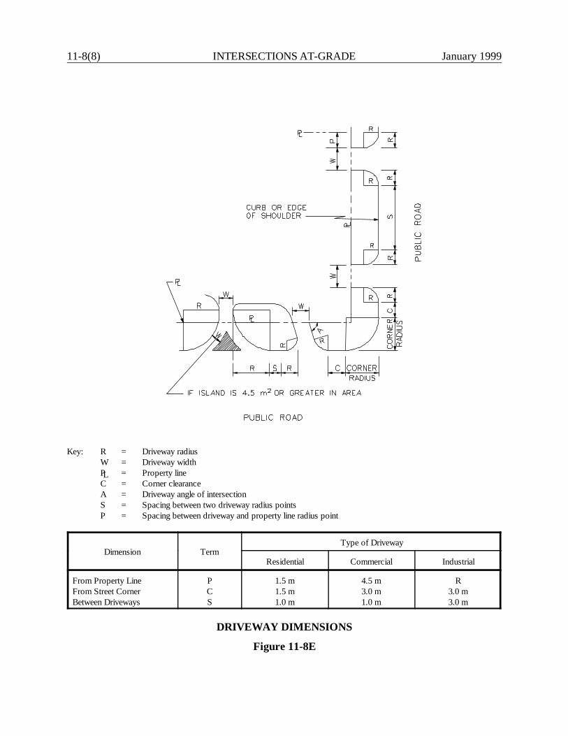
11-8(8) INTERSECTIONS AT-GRADE January 1999
Key: R = Driveway radiusW = Driveway widthPL = Property lineC = Corner clearanceA = Driveway angle of intersectionS = Spacing between two driveway radius pointsP = Spacing between driveway and property line radius point
Dimension TermType of Driveway
Residential Commercial Industrial
From Property LineFrom Street CornerBetween Driveways
PCS
1.5 m1.5 m1.0 m
4.5 m3.0 m1.0 m
R3.0 m3.0 m
DRIVEWAY DIMENSIONS
Figure 11-8E
January 1999 INTERSECTIONS AT-GRADE 11-8(9)
Note: This excerpt has retained the English units from the 1992 version.
Section 13b-11-15 "Driveways"from the
Highway Encroachment Permit Regulations
Approval of an application for a permit for a driveway shall be subject to Sec. 13a-143a Driveway Permits, which reads “No person shall construct a new driveway or relocatean existing driveway leading onto a state highway without first obtaining a permit from theCommissioner of Transportation. In determining the advisability of issuing such permit,the Commissioner shall include, in his consideration, the location of the driveway withrespect to its effect on highway drainage, highway safety, the width and character of thehighways affected, the density of traffic thereon, and the character of such traffic. Theperson to whom the permit is issued shall comply with the provisions and restrictionscontained therein at his own expense.”
Such approval shall also be subject to the following conditions:(1) The applicant is the owner of the property, or owner jointly with the contractor,
and any driveway approach constructed is for the bona fide purpose of securing accessto the property and not for the purpose of parking or servicing vehicles on the highwayright-of-way.
(2) Any driveway, approach or improvement constructed under permit within theright-of-way shall be subject to inspection at any time by the State. The DistrictMaintenance Manager reserves the right to require such changes, additions andrelocations thereto as, in the manager’s opinion, may be necessary for the relocation,reconstruction, widening or maintenance of the highway or to provide protection to life andproperty on or adjacent to the highway.
(3) No driveway, approach or other improvement constructed on the right-of-way,under permit, shall be relocated, or its dimensions altered, without written permission ofthe District Maintenance Manager.
(4) The applicant agrees to comply with all insurance requirements set forth insection 13b-17-9 of these regulations.
(5) The proposed location, design and construction of any driveways under permitshall be evaluated by the State in accordance with the following criteria:
(a) For permit purposes, the priority of use by the abutting land-owner of thatportion of the roadside fronting on his/her land shall be confined between lines drawn fromthe frontage corners of the property to the centerline of the roadway either at right anglesto the centerline on tangents or on a radial line on curves.
(b) No more than one combination entrance and exit shall be allowed for anyproperty with frontage of less than 50 feet. Parcels having a frontage from 50 to 100 feetmay be permitted two entrances if a minimum of one-third of the total frontage is used toseparate driveways. Lots with frontage in excess of 100 feet shall conform to suchdriveway and channelization layout as the District Maintenance Manager shall prescribe.
(c) The width of any entrance or exit shall not exceed 30 feet, measured parallelto the direction of the State highway at the property line, except as may otherwise bedesignated by the District Maintenance Manager because of municipal ordinance or other
11-8(10) INTERSECTIONS AT-GRADE January 1999
valid reason. The area within State property between the entrance and exit shall not beimproved to facilitate vehicular traffic or parking. This area shall be considered restrictedand may be developed on as hereinafter provided in paragraph (1).
(d) The grade of entrances and exits shall conform to current Highway DesignStandards for typical treatment of drives.
(e) In rural or suburban regions, no entrance or exit shall be so constructed thatany part of such entrance or exit is less than ten feet from the extended common boundaryseparating adjacent private properties, except for returns, the radius of which shall notexceed 50 feet. In urban areas, or where there is a curb and gutter, the distance from theboundary may be five feet. See paragraph 5(a) above for limitations on radius termini.
(f) The construction of parking areas on the highway right-of-way is prohibited,except as provided for under the regulations governing parking areas under lease withinthe highway right-of-way. Places of business requiring parking space for their customersshall provide such facilities on their own premises.
(g) Drainage discharged from a State highway or flowing within the right-of-wayshall not be altered or impeded and the permittee must provide suitable drainagestructures as directed by the District Maintenance Manager.
(h) When a curb and gutter are removed, the entrance and exit shall beconstructed so that the curbing along the highway shall be returned into the entrance andexit on a radius of not less than 2 feet or more than 50 feet unless otherwise directed bythe District Maintenance Manager.
(i) All entrances and exits shall be so located that vehicle operators approachingor using them shall have adequate sight distances in both directions along the Statehighway in accordance with current Department of Transportation geometric designstandards. All slopes shall be stabilized by the permit applicant by loaming and seedingor other method directed by the Permit Inspector.
(j) All entrances and exits constructed under permit shall be paved on the entiresection within the State highway right-of-way with bituminous concrete, portland cementconcrete, or as directed by the District Maintenance Manager. The remainder of the areagraded to drain to the State highway shall be stabilized to prevent erosion and washingof material onto the State highway. All costs of such paving shall be borne by thepermittee. The pavement shall be joined in a straight line at its intersection with the Statehighway shoulder and shaped as the Inspector shall require to accommodate highwaydrainage.
(k) No entrance or exit shall be constructed at the intersection of two Statehighways, town road, or city street within the area lines drawn perpendicular to thecenterline of the highway from points on the right-of-way lines, for a distance of 25 feetfrom the intersection of said right-of-way lines at non-signalized intersections. Drivewaysat signalized intersections shall be constructed as directed by the District MaintenanceManager. (l) The area between entrances and exits and those portions of rights-of-way whichhave been defined herein above in (c) as restricted area may be filled in only when surfacedrainage is provided, so that all surface water on the improved area is carried away fromthe highway roadbed and shoulder in a suitable manner, and when the drainage facilityinstalled under any filled area is adequate to carry the water along the State highway. Noheadwall or other structure so designed as to be a hazard to an errant vehicle shall be
January 1999 INTERSECTIONS AT-GRADE 11-8(11)
constructed in the highway right-of-way within the clear zone as specified in theGuidelines for Highway Design. The District Maintenance Manager will determine whetheror not berms or curbs are to be constructed around this separating island area and alsoalong the edges of any end island area. Driveway side slopes within the highway clearzone should not exceed 1:6 maximum.
(m) At locations of new, single homes being constructed adjacent to and lowerthan the State highway pavement, the property owner is required to grade the frontagewithin highway limits so as to confine highway surface water to the gutter or construct abituminous concrete berm. These berms, either grassed earth or bituminous concrete, aremaintained by the State upon satisfactory completion by the permittee. Particular caremust be exercised to see that the permittee constructs driveway entrances so as to confinesurface drainage to the highway gutter.
(n) At new housing developments, shopping centers, industrial parks, and similardevelopments, the owner shall be required to construct a bituminous concrete lip curbadjacent to the gutter along the entire frontage of the property being developed unlessotherwise directed by the District Maintenance Manager.
(o) In instances where the property abutting a State highway is already developedand it becomes necessary to construct a bituminous concrete berm to confine the highwaysurface drainage, the total cost of constructing the berm is the obligation of theDepartment.

11-8(12) INTERSECTIONS AT-GRADE January 1999
January 1999 INTERSECTIONS AT-GRADE 11-9(1)
11-9.0 REFERENCES
1. A Policy on Geometric Design of Highways and Streets, AASHTO, 1994.
2. Highway Capacity Manual, TRB, 1994.
3. NCHRP Synthesis 225, Left-Turn Treatments at Intersections, TRB, 1996.
4. Manual on Uniform Traffic Control Devices, FHWA, 1988.
5. NCHRP 279, Intersection Channelization Design Guide, TRB, 1985.
6. Guidelines for Driveway Location and Design, ITE, 1987.
7. "Volume Warrants for Left-Turn Storage Lanes at Unsignalized Grade Intersections," M.D.Harmelink, Highway Research Record 211, 1967.
8. "Parameters Affecting Intersection Sight Distance", Special Studies Unit, Connecticut Departmentof Transportation, October, 1985.
9. NCHRP 375, Median Intersection Design, TRB, 1995.
10. Highway Encroachment Permit Regulations, Connecticut Department of Transportation, 1992.
11. "Major Traffic Generators Procedure for Engineering and Preparation of State Traffic CommissionReport", Connecticut State Traffic Commission, January, 1977.

11-9(2) INTERSECTIONS AT-GRADE January 1999
January 1999 INTERCHANGES 12-i
Chapter Twelve
INTERCHANGES
Table of Contents
Page
12-1.0 GENERAL . . . . . . . . . . . . . . . . . . . . . . . . . . . . . . . . . . . . . . . . . . . . . . . . . . . . 12-1(1)
12-1.01 Warrants . . . . . . . . . . . . . . . . . . . . . . . . . . . . . . . . . . . . . . . . . . . . . 12-1(1)
12-1.01.01 Guidelines . . . . . . . . . . . . . . . . . . . . . . . . . . . . . . . . . 12-1(1) 12-1.01.02 New/Revised Interchanges on the Interstate System . . 12-1(2)
12-1.02 Interchange Type Selection . . . . . . . . . . . . . . . . . . . . . . . . . . . . . . . . 12-1(4)
12-1.02.01 General Evaluation . . . . . . . . . . . . . . . . . . . . . . . . . . . 12-1(4) 12-1.02.02 Types . . . . . . . . . . . . . . . . . . . . . . . . . . . . . . . . . . . . 12-1(4)
12-2.0 TRAFFIC OPERATIONAL FACTORS . . . . . . . . . . . . . . . . . . . . . . . . . . . . . . 12-2(1)
12-2.01 Basic Number of Lanes and Lane Balance . . . . . . . . . . . . . . . . . . . . 12-2(1) 12-2.02 Lane Reductions . . . . . . . . . . . . . . . . . . . . . . . . . . . . . . . . . . . . . . . 12-2(1) 12-2.03 Distance Between Successive Freeway/Ramp Junctions . . . . . . . . . . 12-2(5) 12-2.04 Safety Considerations . . . . . . . . . . . . . . . . . . . . . . . . . . . . . . . . . . . . 12-2(5) 12-2.05 Capacity and Level of Service . . . . . . . . . . . . . . . . . . . . . . . . . . . . . 12-2(10)12-2.06 Collector-Distributor Roads . . . . . . . . . . . . . . . . . . . . . . . . . . . . . . . 12-2(10)
12-3.0 FREEWAY/RAMP JUNCTIONS . . . . . . . . . . . . . . . . . . . . . . . . . . . . . . . . . . 12-3(1)
12-3.01 Exit Ramps . . . . . . . . . . . . . . . . . . . . . . . . . . . . . . . . . . . . . . . . . . . 12-3(1)
12-3.01.01 Deceleration Lanes . . . . . . . . . . . . . . . . . . . . . . . . . . 12-3(1) 12-3.01.02 Sight Distance . . . . . . . . . . . . . . . . . . . . . . . . . . . . . . 12-3(1) 12-3.01.03 Superelevation . . . . . . . . . . . . . . . . . . . . . . . . . . . . . . 12-3(5) 12-3.01.04 Gore Area . . . . . . . . . . . . . . . . . . . . . . . . . . . . . . . . . 12-3(5) 12-3.01.05 Cross Slope Rollover . . . . . . . . . . . . . . . . . . . . . . . . . 12-3(6)
12-3.02 Entrance Ramps . . . . . . . . . . . . . . . . . . . . . . . . . . . . . . . . . . . . . . . . 12-3(6)
12-3.02.01 Acceleration Lanes . . . . . . . . . . . . . . . . . . . . . . . . . . 12-3(6) 12-3.02.02 Sight Distance . . . . . . . . . . . . . . . . . . . . . . . . . . . . . . 12-3(10)12-3.02.03 Superelevation . . . . . . . . . . . . . . . . . . . . . . . . . . . . . . 12-3(10)
12-3.03 Critical Design Elements . . . . . . . . . . . . . . . . . . . . . . . . . . . . . . . . . . 12-3(10)
12-ii INTERCHANGES January 1999
Table of Contents(Continued)
Page
12-4.0 RAMP DESIGN . . . . . . . . . . . . . . . . . . . . . . . . . . . . . . . . . . . . . . . . . . . . . . . 12-4(1)
12-4.01 Design Speed . . . . . . . . . . . . . . . . . . . . . . . . . . . . . . . . . . . . . . . . . . 12-4(1) 12-4.02 Cross Section . . . . . . . . . . . . . . . . . . . . . . . . . . . . . . . . . . . . . . . . . 12-4(2) 12-4.03 Horizontal Alignment . . . . . . . . . . . . . . . . . . . . . . . . . . . . . . . . . . . . 12-4(3) 12-4.04 Vertical Alignment . . . . . . . . . . . . . . . . . . . . . . . . . . . . . . . . . . . . . . 12-4(6)
12-5.0 RAMP/CROSSING ROAD INTERSECTION . . . . . . . . . . . . . . . . . . . . . . . . 12-5(1)
12-5.01 Design of At-Grade Intersections . . . . . . . . . . . . . . . . . . . . . . . . . . . 12-5(1) 12-5.02 Frontage Road Intersection . . . . . . . . . . . . . . . . . . . . . . . . . . . . . . . 12-5(4) 12-5.03 Access Control . . . . . . . . . . . . . . . . . . . . . . . . . . . . . . . . . . . . . . . . 12-5(4)
12-6.0 REFERENCES . . . . . . . . . . . . . . . . . . . . . . . . . . . . . . . . . . . . . . . . . . . . . . . . . 12-6(1)
January 1999 INTERCHANGES 12-1(1)
Chapter TwelveINTERCHANGES
12-1.0 GENERAL
12-1.01 Warrants
12-1.01.01 Guidelines
Although an interchange is a high-level compromise for intersection problems, its high cost andenvironmental impact require that interchanges only be used after careful consideration of its costsand benefits. Because of the great variance in specific site conditions, ConnDOT has not adoptedspecific interchange warrants. When determining the need for an interchange or grade separation,the following guidelines should be considered:
1. Design Designation. Once it has been decided to provide a fully access-controlled facility,each intersecting highway must be terminated, rerouted, provided a grade separation orprovided an interchange. The importance of the continuity of the crossing road and thefeasibility of an alternative route will determine the need for a grade separation orinterchange. An interchange should be provided on the basis of the anticipated demand foraccess to the minor road.
On facilities with partial control of access, intersections with public roads will beaccommodated by an interchange or with an at-grade intersection; grade separations aloneare not normally provided. Typically, an interchange will be selected for the higher-volumeintersecting roads. Therefore, on a facility with partial control of access, the decision toprovide an interchange will be, in general, based on the criteria in the following comments.
2. Functional Classification. Interchanges will be provided at all freeway-to-freeway crossings.On fully access-controlled facilities, interchanges should be provided with all majorhighways, unless this is determined inappropriate for other reasons. Interchanges to otherhighways may be provided if practical.
3. Congestion. An interchange may be considered where the level of service (LOS) at an at-grade intersection is unacceptable, and the intersection cannot be redesigned at-grade tooperate at an acceptable LOS. Although LOS criteria is the most tangible of any interchange
12-1(2) INTERCHANGES January 1999
guideline, ConnDOT has not adopted any specific levels which, when exceeded, woulddemand an interchange.
4. Safety. The accident reduction benefits of an interchange should be considered at an existingat-grade intersection which has a high accident rate. Section 12-2.04 provides additionalinformation on various safety considerations relative to interchange selection.
5. Site Topography. At some sites the topography may be more adaptable to an interchangethan an at-grade intersection.
6. Road-User Benefits. Interchanges significantly reduce the travel time when compared to at-grade intersections but may increase the travel distances. If an analysis reveals that road-userbenefits over the service life of the interchange will exceed costs, then an interchange maybe considered.
7. Traffic Volumes. A traffic volume warrant is the most tangible of any interchange warrant.Although the Department has not adopted specific numbers which, when exceeded, woulddemand an interchange, it is still an important factor. For example, the point at whichvolumes for an at-grade intersection exceed capacity may warrant an interchange, if the at-grade intersection cannot be practically upgraded. In addition, other factors, such as costs,right-of-way and environmental concerns, need to be considered.
8. Interchange Spacing. When interchanges are spaced farther apart, freeway operations areimproved. Spacing of urban interchanges between interchange crossroads should not be lessthan 1.5 km. This should allow for adequate distance for an entering driver to adjust to thefreeway environment, to allow for proper weaving maneuvers between entrance and exitramps, and to allow for adequate advance and exit signing. In urban areas, a spacing of lessthan 1.5 km may be developed by grade-separated ramps or by collector-distributor roads.In rural areas, interchanges should not be spaced less than 5 km apart on the Interstate systemor 3 km on other systems.
12-1.01(02) New/Revised Interchanges on the Interstate System
The Department’s goal is to maintain the highest practical level of service, safety and mobility onits Interstate System. Among other design features, this is accomplished by controlling access ontothe system. In general, new access points on existing fully access-controlled facilities arediscouraged. Proposals for new or revised access points on an existing Interstate must fully addressthe following considerations:

January 1999 INTERCHANGES 12-1(3)
1. Traffic Volumes. The proposal must demonstrate that existing interchanges and/or localroads and streets within the corridor cannot satisfactorily accommodate, nor can the existingnetwork be feasibly improved to accommodate, the expected design-year traffic volumes.
2. Alternatives. The proposal must demonstrate that all reasonable alternatives for designoptions, locations and transportation system management type improvements (e.g., rampmetering, mass transit, HOV facilities) have been evaluated, provided for, and/or provisionmade for future incorporation.
3. Impacts. The proposed new access point should not have a significant adverse impact on thesafety and operation of the Interstate facility based on an analysis of current and future traffic(e.g., 20 years in the future). The operational analysis for existing conditions should include:
a. an analysis of Interstate sections to, and including, at least the first adjacent existingor proposed interchange on either side; and
b. an analysis of crossroads and other roads/streets to ensure their ability to collect anddistribute traffic to and from the proposed interchange.
4. Connections. The proposed new interchange will only be connected to a public road, and itwill provide for all traffic movements. Less than "full interchanges" for special purposeaccess for transit vehicles, for HOV entrances or to park-and-ride lots may be considered ona case-by-case basis.
5. Land Use. The proposal must address the consistency of the interchange with local andregional development plans and transportation system improvements. For possible multipleinterchange additions, the proposal must be supported by a comprehensive Interstate networkstudy which should address all proposed and desired access within the context of a long-termplan.
6. New/Expanded Development. Where new or revised access is requested, due to a proposedor expanded development, document that the appropriate coordination has taken place withthe developer in conjunction with other transportation system improvements.
7. Design. The Department's design criteria for interchanges as presented in this chapter mustbe met or adequately addressed.
All proposed new or revised access points on the Interstate System will require formal approval fromthe FHWA. See Federal Register, Vol. 55, No. 204, Monday, 10-22-90.

12-1(4) INTERCHANGES January 1999
Each entrance and exit point on the mainline, including "locked gate" access (e.g., utility opening), isdefined as an access point (e.g., diamond interchanges have four access points). A revised access isconsidered to be a change in the interchange configuration even though the number of access pointsmay not change (e.g., replacing a diamond interchange ramp with a loop).
12-1.02 Interchange Type Selection
12-1.02.01 General Evaluation
The AASHTO A Policy on Geometric Design of Highways and Streets presents the various interchangetypes which may be used at a given site. The Office of Intermodal Project Planning normallydetermines the type of interchange for the site. Typically, the Office will evaluate several types forpotential application considering:
1. compatibility with the surrounding highway system;2. route continuity;3. level of service for each interchange element (e.g., freeway/ramp junction, ramp proper);4. operational characteristics (e.g., single versus double exits, weaving, signing);5. road user impacts (e.g., travel distance and time, safety, convenience, comfort);6. driver expectancy;7. geometric design;8. construction and maintenance costs;9. potential for stage construction;10. right-of-way impacts and availability;11. environmental impacts; and12. potential growth of surrounding area.
All interchanges should provide for all movements, even when the anticipated turning volume is low.An omitted movement may cause confusion to those drivers searching for the exit or entrance. Inaddition, unanticipated future developments may increase the demand for that movement.
12-1.02.02 Types
This section presents the basic types of interchanges in Connecticut. The AASHTO A Policy onGeometric Design of Highways and Streets discusses the advantages and disadvantages for eachinterchange type. Each interchange must be custom-designed to fit the individual site considerations.The final design may be a minor or major modification of one of the basic types or may be acombination of two or more basic types. The following are the basic types of interchanges used inConnecticut:

January 1999 INTERCHANGES 12-1(5)
1. Three-Leg. Three-leg interchanges, also known as T- or Y-interchanges, are provided atintersections with three legs.
2. Diamond. The diamond is the simplest and perhaps the most common type of interchange.One-way diagonal ramps are provided in each quadrant with two at-grade intersectionsprovided at the minor road. If these two intersections can be properly designed, the diamondis usually the best choice of interchange where the intersecting road is not access controlled.
3. Single Point Urban Interchange. The single point urban interchange is a special type ofdiamond interchange. With this interchange, all legs of the interchange meet at a singlepoint. It can significantly increase the interchange capacity, alleviate the operationalproblems of having two closely spaced at-grade intersections on the minor road, andovercome the left-turn lane storage problem for drivers wishing to enter the freeway.
4. Full Cloverleafs. Cloverleaf interchanges are used at 4-leg intersections and employ loopramps to accommodate left-turn movements. Loops may be provided in any number ofquadrants. Full cloverleaf interchanges are those with loops in all four quadrants; all othersare partial cloverleafs.
5. Partial Cloverleafs. Partial cloverleaf interchanges are those with loops in one, two or threequadrants. They are appropriate where right-of-way restrictions preclude ramps in one ormore quadrants. They are also advantageous where a left-turn movement can be providedonto the major road by a loop without the immediate presence of an entrance loop from theminor road.
6. Directional and Semi-Directional. Directional or semi-directional interchanges are used forheavy left-turn movements to reduce travel distance, to increase speed and capacity and toeliminate weaving. These types of connections allow an interchange to operate at a betterlevel of service than is possible with cloverleaf interchanges.

12-1(6) INTERCHANGES January 1999
January 1999 INTERCHANGES 12-2(1)
12-2.0 TRAFFIC OPERATIONAL FACTORS
Several traffic operational factors are important in the design of an interchange. Adhering to thesefactors will minimize confusion, operational problems and the number of accidents. The designermust work closely with the Design Development Team to ensure that all operational factors areproperly considered.
12-2.01 Basic Number of Lanes and Lane Balance
The basic number of lanes is the minimum number of lanes over a significant length of highwaybased on the overall capacity needs of that section. The number of lanes should remain constant overshort distances. For example, a lane should not be dropped at the exit of a diamond interchange andthen added at the downstream entrance simply because the traffic volume between the exit andentrance drops significantly. A basic lane should also not be dropped between closely spacedinterchanges simply because the estimated traffic volume in that short section of highway does notwarrant the higher number of lanes.
The number of lanes on the freeway mainline should not be reduced by more than one lane at an exitor increased by more than one lane at an entrance. This principle is lane balance. It would prohibit,for example, dropping two lanes at a 2-lane exit ramp. One lane must provide the option ofremaining on the freeway.
Figure 12-2A illustrates how to coordinate lane balance and the basic number of lanes at aninterchange. Figure 12-2B illustrates how to achieve lane balance at the merging and diverging pointsof branch connections.
12-2.02 Lane Reductions
Freeway lane drops, where the basic number of lanes is decreased, must be carefully designed. Theyshould occur on the freeway mainline away from any other turbulence, such as interchange exits andentrances. Figure 12-2C illustrates the recommended design of a lane drop beyond an interchange.The following criteria are important when designing a freeway lane drop:
1. Location. The lane drop should occur 600 m to 900 m beyond the previous interchange. Thisdistance allows adequate signing and driver adjustments from the interchange, but yet is notso far downstream that drivers become accustomed to the number of lanes and are surprisedby the lane drop. In addition, a lane should not be dropped on a horizontal curve or whereother signing is required, such as for an upcoming exit.
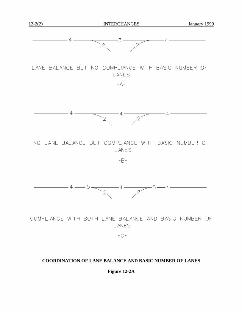
12-2(2) INTERCHANGES January 1999
COORDINATION OF LANE BALANCE AND BASIC NUMBER OF LANES
Figure 12-2A
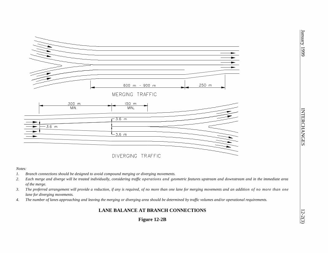
January 1999 IN
TERC
HA
NG
ES12-2(3)
Notes:1. Branch connections should be designed to avoid compound merging or diverging movements.2. Each merge and diverge will be treated individually, considering traffic operations and geometric features upstream and downstream and in the immediate area
of the merge.3. The preferred arrangement will provide a reduction, if any is required, of no more than one lane for merging movements and an addition of no more than one
lane for diverging movements.4. The number of lanes approaching and leaving the merging or diverging area should be determined by traffic volumes and/or operational requirements.
LANE BALANCE AT BRANCH CONNECTIONS
Figure 12-2B
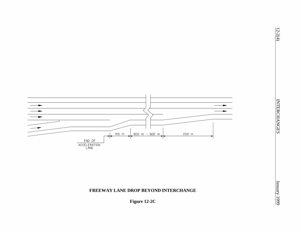
12-2(4)IN
TERC
HA
NG
ESJanuary 1999
FREEWAY LANE DROP BEYOND INTERCHANGE
Figure 12-2C
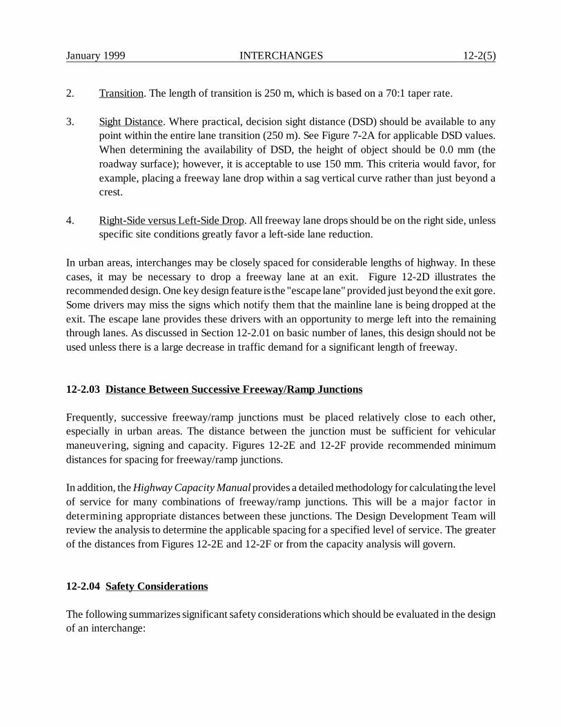
January 1999 INTERCHANGES 12-2(5)
2. Transition. The length of transition is 250 m, which is based on a 70:1 taper rate.
3. Sight Distance. Where practical, decision sight distance (DSD) should be available to anypoint within the entire lane transition (250 m). See Figure 7-2A for applicable DSD values.When determining the availability of DSD, the height of object should be 0.0 mm (theroadway surface); however, it is acceptable to use 150 mm. This criteria would favor, forexample, placing a freeway lane drop within a sag vertical curve rather than just beyond acrest.
4. Right-Side versus Left-Side Drop. All freeway lane drops should be on the right side, unlessspecific site conditions greatly favor a left-side lane reduction.
In urban areas, interchanges may be closely spaced for considerable lengths of highway. In thesecases, it may be necessary to drop a freeway lane at an exit. Figure 12-2D illustrates therecommended design. One key design feature is the "escape lane" provided just beyond the exit gore.Some drivers may miss the signs which notify them that the mainline lane is being dropped at theexit. The escape lane provides these drivers with an opportunity to merge left into the remainingthrough lanes. As discussed in Section 12-2.01 on basic number of lanes, this design should not beused unless there is a large decrease in traffic demand for a significant length of freeway.
12-2.03 Distance Between Successive Freeway/Ramp Junctions
Frequently, successive freeway/ramp junctions must be placed relatively close to each other,especially in urban areas. The distance between the junction must be sufficient for vehicularmaneuvering, signing and capacity. Figures 12-2E and 12-2F provide recommended minimumdistances for spacing for freeway/ramp junctions.
In addition, the Highway Capacity Manual provides a detailed methodology for calculating the levelof service for many combinations of freeway/ramp junctions. This will be a major factor indetermining appropriate distances between these junctions. The Design Development Team willreview the analysis to determine the applicable spacing for a specified level of service. The greaterof the distances from Figures 12-2E and 12-2F or from the capacity analysis will govern.
12-2.04 Safety Considerations
The following summarizes significant safety considerations which should be evaluated in the designof an interchange:
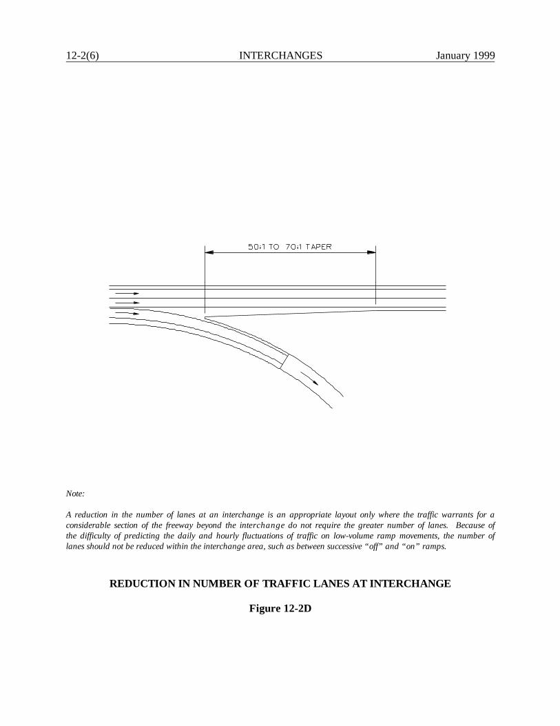
12-2(6) INTERCHANGES January 1999
Note:
A reduction in the number of lanes at an interchange is an appropriate layout only where the traffic warrants for aconsiderable section of the freeway beyond the interchange do not require the greater number of lanes. Because ofthe difficulty of predicting the daily and hourly fluctuations of traffic on low-volume ramp movements, the number oflanes should not be reduced within the interchange area, such as between successive “off” and “on” ramps.
REDUCTION IN NUMBER OF TRAFFIC LANES AT INTERCHANGE
Figure 12-2D
January 1999 IN
TERC
HA
NG
ES12-2(7)
Note:
The spacing of exit terminals should be based upon considerations of signing to permit the driver adequate time to make decisions. Exit terminals should not bespaced closer than 1.5 km except where conditions, such as ramp or local terminal capacity, may make it necessary to reduce this distance. 450 m is consideredthe minimum distance between exit terminals which will provide safe and efficient operation. Closer spacings should only be used under the lower speed situationprovided by the distributor road arrangement shown in the upper sketch. In addition, the Highway Capacity Manual should be used to determine the actualdistance based on a specified level of service.
SUCCESSIVE EXIT TERMINAL SPACINGS
Figure 12-2E

12-2(8)IN
TERC
HA
NG
ESJanuary 1999
Note:
The spacing of entrance terminals should be based upon considerations of maintaining smooth operations on the through traffic lanes. Entrance terminals oftencause turbulence which should not extend through successive entrance areas. 100 m is considered the minimum distance of normal cross section necessary forthe turbulence associated with lane changing to subside. Where closer spacing of entrance terminals is required, the collector road detail shown in the uppersketch may be employed. In addition, the Highway Capacity Manual should be used to determine the actual distance based on a specified level of service.
SUCCESSIVE ENTRANCE TERMINAL SPACINGS
Figure 12-2F
January 1999 INTERCHANGES 12-2(9)
1. Exit Points. Where practical, provide decision sight distance at freeway exits, and use thepavement surface for the height of object (0.0 mm). A 150-mm height of object isacceptable. See Section 12-3.01 for the application of decision sight distance to freewayexits. Proper advance signing of exits is also essential.
2. Exit Speed Changes. The design should provide enough distance to allow safe deceleration
from the freeway design speed to the design speed of the first governing geometric featureon the ramp, typically the horizontal exit curve. See Section 12-3.01 for applicable valuesfor deceleration length.
3. Merges. Rear-end collisions on entrance merges onto a freeway may result from a driverattempting the complicated maneuver of simultaneously searching for a gap in the mainlinetraffic stream and watching for vehicles in front. An acceleration distance of sufficientlength should be provided to allow a merging vehicle to attain speed and find a sufficient gapto merge into.
4. Fixed-Object Accidents. A number of fixed objects may be located within interchanges, suchas signs at exit gores or bridge piers. These should be removed where practical, madebreakaway, or shielded with barriers or crash cushions. See Chapter Thirteen for a detaileddiscussion on roadside safety.
5. Wrong-Way Entrances. In almost all cases, wrong-way maneuvers originate at interchanges.Some cannot be avoided, but many result from driver confusion due to poor visibility,deceiving ramp arrangement or inadequate signing. The interchange design must attempt tominimize wrong-way possibilities. The designer should coordinate with the Division ofTraffic Engineering to achieve this objective.
6. Incomplete Interchanges. If practical, the designer should ensure that all movements areprovided at an interchange, even if projected turning volumes are low. A missing movementmay cause confusion for those drivers seeking that movement. In addition, if future demandfor the movement increases, it may be relatively expensive and disruptive to provide theconnection.
7. Driver Expectancy. Interchanges can be significant sources of driver confusion; therefore,they should be designed to conform to the principles of driver expectancy. Several of theseprinciples are discussed below:
a. Avoid using left-hand exits and entrances. It is difficult for a driver entering from aramp to safely merge with the high-speed left lane on the mainline. Therefore, leftexits and entrances should not be used, because they are not consistent with the
12-2(10) INTERCHANGES January 1999
concept of driver expectancy when they are mixed with right-hand entrances andexits.
b. Do not place exits in line with the freeway tangent section at the point of mainlinecurvature to the left.
c. Avoid placing exits beyond structures.
12-2.05 Capacity and Level of Service
The capacity of an interchange will depend upon the operation of its individual elements:
1. basic freeway section where interchanges are not present,2. freeway/ramp junctions,3. weaving areas,4. ramp proper, and5. ramp/crossing road intersection.
The basic capacity reference is the Highway Capacity Manual (HCM). The HCM provides theanalytical tools to analyze the level of service for each element listed above.
The interchange should operate at an acceptable level of service. The level of service valuespresented in Figures 4A and 5A for freeways will also apply to interchanges. The level of service ofeach interchange element should be as good as the level of service provided on the basic freewaysection. At a minimum, interchange elements should not operate at more than one level of servicebelow that of the basic freeway section. In addition, the operation of the ramp/crossing roadintersection in urban areas should not impair the operation of the mainline. This will likely involvea consideration of the operational characteristics on the minor road for some distance in eitherdirection from the interchange. The Design Development Team is responsible for conducting thecapacity analyses for all interchange elements. However, coordinate the capacity analyses atramp/crossing road intersections with the Division of Traffic Engineering.
12-2.06 Collector-Distributor Roads
Collector-distributor (C-D) roads are sometimes provided within an interchange to improve itsoperational characteristics. C-D roads will:

January 1999 INTERCHANGES 12-2(11)
1. remove weaving maneuvers from the mainline,2. provide single exits and entrances from the mainline, and3. provide all mainline exits in advance of the structure.
C-D roads are most often warranted when traffic volumes are so high that the interchange withoutthem cannot operate at an acceptable level of service, especially in weaving sections. C-D roadsmay be one or two lanes, depending upon the traffic volumes and weaving conditions. Lane balanceshould be maintained at the exit and entrance points of the C-D road. The design speed should bethe same as the mainline, but not more than 20 km/h below the mainline. The separation betweenthe C-D road and mainline should be as wide as practical, but not less than that required to providethe applicable shoulder widths and a longitudinal barrier between the two.

12-2(12) INTERCHANGES January 1999
January 1999 INTERCHANGES 12-3(1)
12-3.0 FREEWAY/RAMP JUNCTIONS
12-3.01 Exit Ramps
12-3.01.01 Deceleration Lanes
Sufficient deceleration distance is needed to safely and comfortably allow an exiting vehicle to leavethe freeway mainline. All deceleration should occur within the full width of the deceleration lane.The length of the deceleration lane will depend upon the design speed of the mainline and the designspeed of the first governing geometric control on the exit ramp. This will most often be a horizontalcurve but could be, for example, stopping sight distance on a vertical curve. Figure 12-3A providesthe deceleration distances for various combinations of highway design speeds and ramp designspeeds. Greater distances should be provided if practical. If the deceleration lane is on a grade of 3%or more, the length of the lane should be adjusted according to the criteria in Figure 12-3B.
The specific use of the deceleration criteria to horizontal curves warrants some elaboration. Thefollowing will apply:
1. Based on the highway design speed and the design speed of the first curve on the exit ramp,Figure 12-3A will yield the required length of the deceleration lane. This will apply from thepoint where the deceleration lane becomes 3.6 m to the PC of the horizontal curve.
2. For compound curves on the ramp, the minimum length of the entering flatter curve shouldallow for safe deceleration to the design speed of the sharper curve. Figure 12-3A providesthe criteria to determine the minimum distance between the PC and PCC or between thePCC and PCC.
Department policy is that taper ramps will be used for all freeway exits. Figure 12-3C illustrates thetypical design for a freeway taper exit. However, at restrictive sites where a taper design cannotprovide the needed deceleration for sharp curvature, a parallel lane may be considered. If used, itshould be introduced with a taper of 25:1. The AASHTO A Policy on Geometric Design ofHighways and Streets provides the design criteria for parallel lane designs.
12-3.01.02 Sight Distance
Where practical, decision sight distance should be provided for drivers approaching an exit. Thissight distance is particularly important for exit loops immediately beyond the structure. Verticalcurvature or bridge piers can obstruct the exit points if not carefully designed. When measuring for
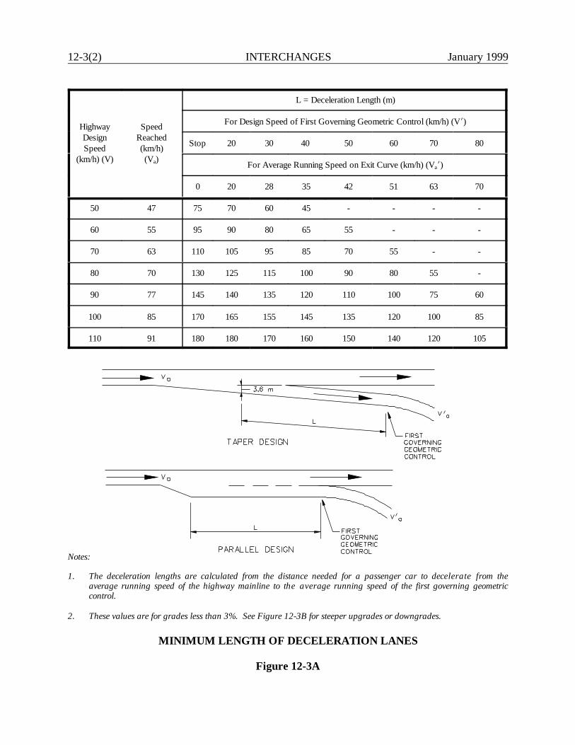
12-3(2) INTERCHANGES January 1999
HighwayDesignSpeed
(km/h) (V)
SpeedReached(km/h)(Va)
L = Deceleration Length (m)
For Design Speed of First Governing Geometric Control (km/h) (Vk)
Stop 20 30 40 50 60 70 80
For Average Running Speed on Exit Curve (km/h) (Vak)
0 20 28 35 42 51 63 70
50 47 75 70 60 45 - - - -
60 55 95 90 80 65 55 - - -
70 63 110 105 95 85 70 55 - -
80 70 130 125 115 100 90 80 55 -
90 77 145 140 135 120 110 100 75 60
100 85 170 165 155 145 135 120 100 85
110 91 180 180 170 160 150 140 120 105
Notes:
1. The deceleration lengths are calculated from the distance needed for a passenger car to decelerate from theaverage running speed of the highway mainline to the average running speed of the first governing geometriccontrol.
2. These values are for grades less than 3%. See Figure 12-3B for steeper upgrades or downgrades.
MINIMUM LENGTH OF DECELERATION LANES
Figure 12-3A

January 1999 INTERCHANGES 12-3(3)
Direction ofGrade
Ratio of Deceleration Lane Length on Grade to Length on Level
< 3% 3% < G < 5% 5% < G < 7% G > 7%
Upgrade 1.0 0.9 0.8 0.7
Downgrade 1.0 1.2 1.35 1.5
Notes: 1. Table applies to all highway design speeds.
2. The "grade" in the table is the average grade over the distance used for measuringthe length of the deceleration lane. See Figure 12-3C.
Example
Given: Highway Design Speed - 110 km/hFirst Exit Curve Design Speed - 70 km/hAverage Grade - 5% downgrade
Problem: Determine length of deceleration lane.
Solution: Figure 12-3A yields a minimum deceleration lane of 120 m on the level. Accordingto Figure 12-3B, this should be increased by 1.35.
Therefore: L = 120 x 1.35L = 162 m
A 162-m deceleration lane would be provided from the full width of the lane to thePC of the first exit curve.
GRADE ADJUSTMENTS ON DECELERATION LANES
Figure 12-3B
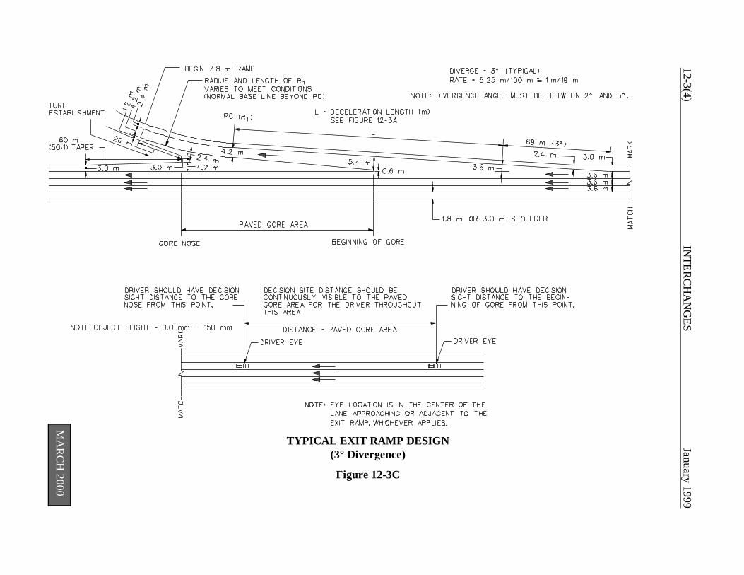
12-3(4)IN
TERC
HA
NG
ESJanuary 1999
MA
RC
H 2000
TYPICAL EXIT RAMP DESIGN(3° Divergence)
Figure 12-3C
January 1999 INTERCHANGES 12-3(5)
adequate sight distance, the height of object should be 0.0 mm (the roadway surface); however, itis acceptable to use 150 mm. Figure 12-3C illustrates the application of the decision sight distanceto freeway exits.
12-3.01.03 Superelevation
The superelevation at an exit ramp must be developed to properly transition the driver from themainline to the curvature at the exit. The principles of superelevation for rural highways and high-speed urban facilities, as discussed in Section 8-2.0, should be applied to the exit ramp design.
The maximum superelevation rate is 6%. Figure 8-2A presents the design superelevation rate forvarious combinations of radii and design speed. Typically, the exit lane should be transitioned so that0.67 of the design superelevation is reached at the PC of the first exit curve. At a minimum, thelength of runoff should be based on the distances provided in Figure 8-2A.
12-3.01.04 Gore Area
The gore area is normally considered to be both the paved triangular area between the through laneand the exit lane, plus the graded area which may extend 100 m or more downstream beyond thegore nose. The following should be considered when designing the gore:
1. Traffic Control Devices. If practical, the area beyond the gore nose should be free of signsand luminaire supports for approximately 100 m beyond the gore nose. If they must bepresent, they must be yielding or breakaway or shielded by guide rail or a crash cushion.(See Chapter Thirteen).
2. Grading. The graded area beyond the gore nose should be as flat as practical. If theelevation between the exit ramp or loop and the mainline increases rapidly, this may not bepractical. These areas will likely be non-traversable and the gore design must shield theseareas from the motorist. At some sites, the vertical divergence of the ramp and mainline willwarrant protection for both roadways beyond the gore.
3. Paved Gore. The paved triangular gore area between the through lane and exit lane shouldbe safely traversable. The effects of snow storage and melt in the gore area design must becarefully considered. The typical gore grading design will collect the highway runoff in aswale section and direct if off the highway into the earth gore or collect it in a subsurfacedrainage system. This will minimize icing problems during winter maintenance activities. Themaximum break in pavement cross slopes through the swale area should not exceed 8% atany point. Where this treatment is not practical, a straight cross slope may be used provideddrainage and snow melt issues are adequately addressed. In no case should the cross slope
12-3(6) INTERCHANGES January 1999
of gore be steeper than the adjacent travel lane cross slope. To ensure adequateconsideration is given to the combination of drainage and geometric factors, carefulevaluation will be necessary early in the design process.
4. Signing. Signing in advance of the exit and at the divergence should be according to currentConnDOT practices. This also applies to the pavement markings in the triangular areaupstream from the gore nose. Signing and pavement markings should be coordinated withthe Division of Traffic Engineering.
12-3.01.05 Cross Slope Rollover
The cross slope rollover is the algebraic difference between the slope of the through lane and theslope of the exit lane, when these two are adjacent to each other (i.e., before the gore begins). Themaximum algebraic difference is 4% to 5%.
12-3.02 Entrance Ramps
12-3.02.01 Acceleration Lanes
A properly designed acceleration lane will facilitate driver comfort, traffic operations and safety. Thelength of the acceleration lane will primarily depend upon the design speed of the last (or controlling)curve on the entrance ramp and the design speed of the mainline. Figure 12-3D provides the criteriafor minimum lengths of acceleration lanes. These lengths are for the full width of the accelerationlane; taper lengths, typically 105 m, are in addition to the table lengths. However, in restrictivelocations, up to 15 m of the taper length may be used to meet the criteria for the accelerationdistance. Where grades of 3 percent or more occur on the acceleration lane, adjustments should bemade in its length according to Figure 12-3E. Figure 12-3F illustrates the typical design for entranceramps. The designer should coordinate with the Design Development Team to determine the actuallength of the acceleration lane.
The values in Figure 12-3D provide sufficient distance for vehicular acceleration; they may notsafely allow a vehicle to merge into the mainline if traffic volumes are high. Where the mainline andramp will carry traffic volumes approaching the design capacity of the merging area, the parallelportion of the acceleration lane should be increased to a maximum of 360 m in length.
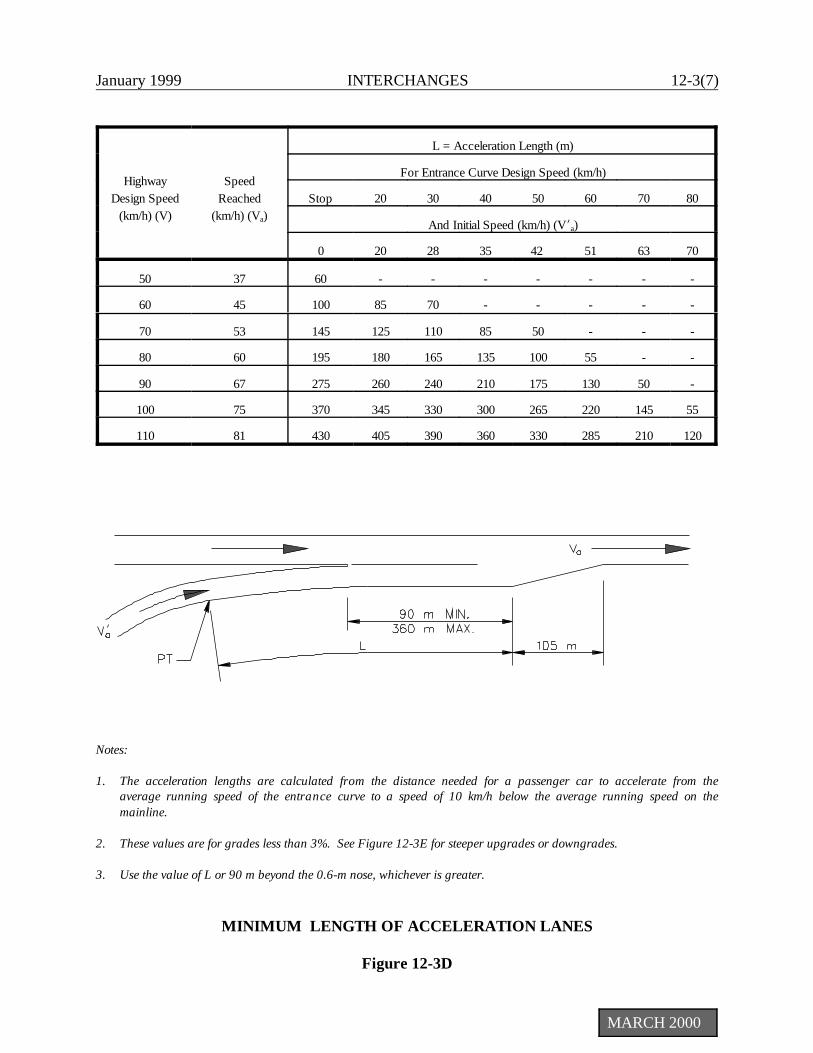
January 1999 INTERCHANGES 12-3(7)
MARCH 2000
HighwayDesign Speed
(km/h) (V)
SpeedReached
(km/h) (Va)
L = Acceleration Length (m)
For Entrance Curve Design Speed (km/h)
Stop 20 30 40 50 60 70 80
And Initial Speed (km/h) (Vka)
0 20 28 35 42 51 63 70
50 37 60 - - - - - - -
60 45 100 85 70 - - - - -
70 53 145 125 110 85 50 - - -
80 60 195 180 165 135 100 55 - -
90 67 275 260 240 210 175 130 50 -
100 75 370 345 330 300 265 220 145 55
110 81 430 405 390 360 330 285 210 120
Notes:
1. The acceleration lengths are calculated from the distance needed for a passenger car to accelerate from theaverage running speed of the entrance curve to a speed of 10 km/h below the average running speed on themainline.
2. These values are for grades less than 3%. See Figure 12-3E for steeper upgrades or downgrades.
3. Use the value of L or 90 m beyond the 0.6-m nose, whichever is greater.
MINIMUM LENGTH OF ACCELERATION LANES
Figure 12-3D
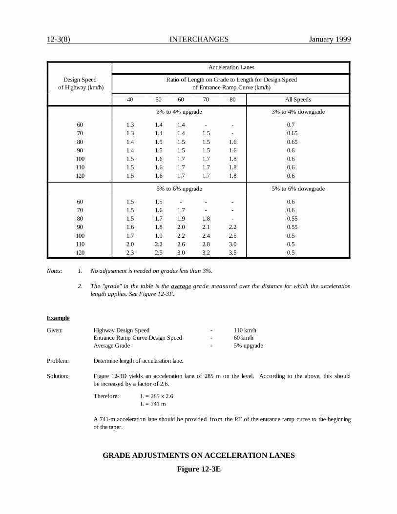
12-3(8) INTERCHANGES January 1999
Design Speed of Highway (km/h)
Acceleration Lanes
Ratio of Length on Grade to Length for Design Speedof Entrance Ramp Curve (km/h)
40 50 60 70 80 All Speeds
3% to 4% upgrade 3% to 4% downgrade
60708090100110120
1.31.31.41.41.51.51.5
1.41.41.51.51.61.61.6
1.41.41.51.51.71.71.7
-1.51.51.51.71.71.7
--
1.61.61.81.81.8
0.70.650.650.60.60.60.6
5% to 6% upgrade 5% to 6% downgrade
60708090100110120
1.51.51.51.61.72.02.3
1.51.61.71.81.92.22.5
-1.71.92.02.22.63.0
--
1.82.12.42.83.2
---
2.22.53.03.5
0.60.60.550.550.50.50.5
Notes: 1. No adjustment is needed on grades less than 3%.
2. The "grade" in the table is the average grade measured over the distance for which the accelerationlength applies. See Figure 12-3F.
Example
Given: Highway Design Speed - 110 km/hEntrance Ramp Curve Design Speed - 60 km/hAverage Grade - 5% upgrade
Problem: Determine length of acceleration lane.
Solution: Figure 12-3D yields an acceleration lane of 285 m on the level. According to the above, this shouldbe increased by a factor of 2.6.
Therefore: L = 285 x 2.6L = 741 m
A 741-m acceleration lane should be provided from the PT of the entrance ramp curve to the beginningof the taper.
GRADE ADJUSTMENTS ON ACCELERATION LANES
Figure 12-3E
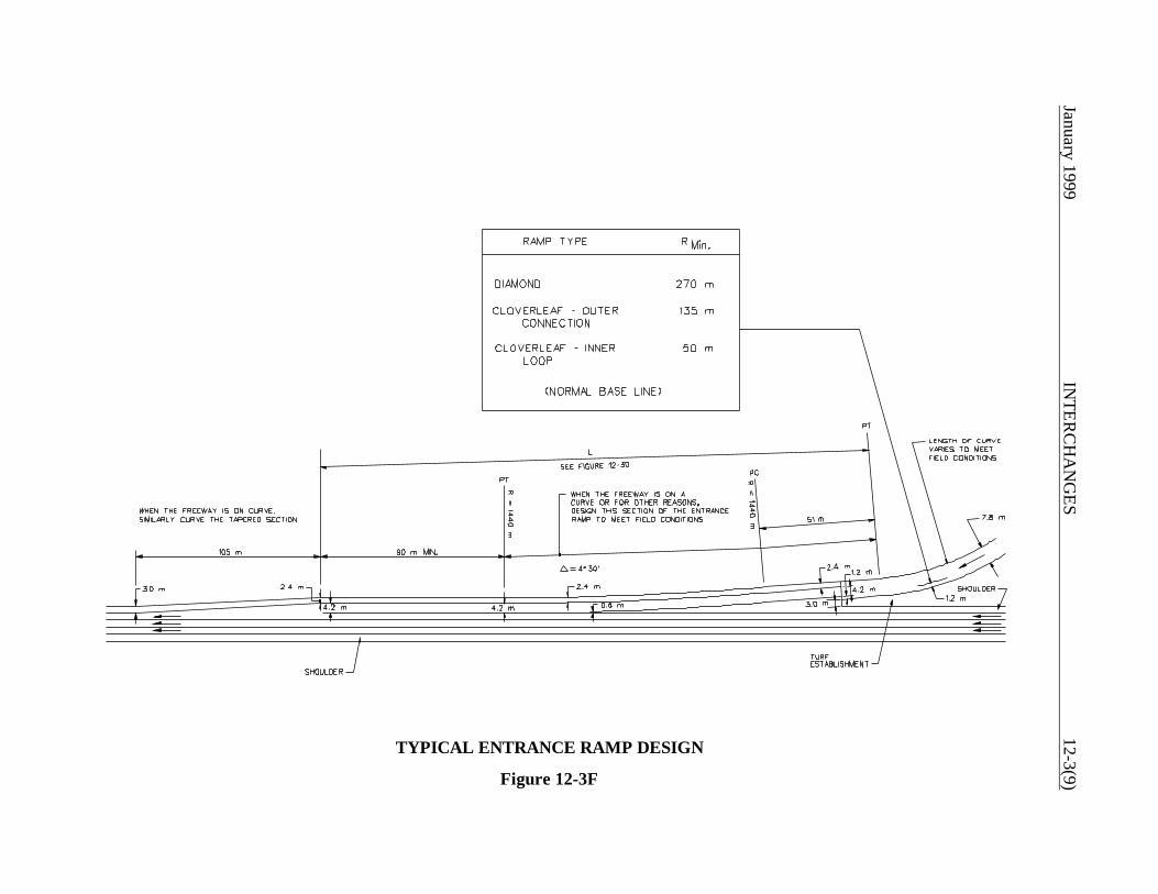
January 1999IN
TERC
HA
NG
ES12-3(9)
TYPICAL ENTRANCE RAMP DESIGN
Figure 12-3F
12-3(10) INTERCHANGES January 1999
12-3.02.02 Sight Distance
Where practical, decision sight distance should be provided for drivers on the mainline approachingan entrance terminal. They need sufficient distance to see the merging traffic so they can adjust theirspeed or change lanes to allow the merging traffic to enter the freeway. Likewise, drivers on theentrance ramp need to see a sufficient distance upstream from the entrance to locate gaps in thetraffic stream for merging.
12-3.02.03 Superelevation
The ramp superelevation should be gradually transitioned to meet the normal cross slope of themainline. The principles of superelevation for rural highways, as discussed in Section 8-2.0, shouldbe applied to the entrance design. The following criteria should be used:
1. The maximum superelevation rate is 6%.
2. The maximum algebraic difference between the slopes of the acceleration lane and throughlane is 4% to 5%, when these two lanes are adjacent to each other.
3. At a minimum the superelevation runoff length should be based on the distance provided inFigure 8-2A.
12-3.03 Critical Design Elements
The designer should provide a freeway/ramp junction design which meets all criteria presented inSection 12-3.0. However, the following elements are especially important to the safety and properoperation of the junction:
1. the minimum length of deceleration for an exit ramp (Figure 12-3A),2. the deflection (taper) angle for a taper exit ramp (Figure 12-3C),3. the minimum length of acceleration for an entrance ramp (Figure 12-3D), and4. the parallel portion of the acceleration lane for an entrance ramp (360 m minimum).
January 1999 INTERCHANGES 12-4(1)
12-4.0 RAMP DESIGN
12-4.01 Design Speed
Figure 12-4A provides the acceptable ranges of ramp design speed based on the design speed of themainline. In addition, the designer should consider the following:
1. Freeway/Ramp Junctions. The design speeds in Figure 12-4A apply to the ramp proper andnot to the freeway/ramp junction. Freeway/ramp junctions are designed using the freewaymainline design speed.
2. At-Grade Terminals. If a ramp will be terminated at an at-grade intersection with a stop orsignal control, the design speeds in the figure may not be applicable to the ramp portion nearthe intersection.
3. Variable Speeds. The ramp design speed may vary based on the two design speeds of theintersecting roadways. Higher design speeds should be used on the portion of the ramp nearthe higher-speed facility while lower design speeds may be selected near the lower-speedfacility. The designer needs to ensure that sufficient deceleration distance is availablebetween design elements with varying design speeds (e.g., two horizontal curves).
4. Ramps for Right Turns. Design speeds for right-turn ramps are typically in the mid to highrange. This includes, for example, a diagonal ramp of a diamond interchange.
5. Loop Ramps. Design speeds in the high range are generally not attainable for loop ramps.For mainline design speeds greater than 80 km/h, the loop design speed should not be lessthan 40 km/h. However, design speeds greater than 50 km/h will require significantly moreright-of-way and may not be practical in urban areas.
6. Semidirect Connections. Design speeds between the mid and high ranges should be used forsemidirect connections. Design speeds less than 50 km/h should not be used. Design speedsgreater than 80 km/h are generally not practical for short, single-lane ramps. For 2-laneramps, values in the mid to high ranges should be used.
7. Direct Connections. For direct connections, the design speed should be in the mid to highrange. The design speed should not be less than 60 km/h.
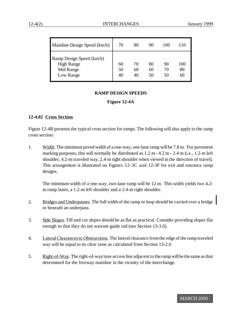
12-4(2) INTERCHANGES January 1999
Mainline Design Speed (km/h) 70 80 90 100 110
Ramp Design Speed (km/h) High Range Mid Range Low Range
605040
706040
806050
907050
1008060
MARCH 2000
RAMP DESIGN SPEEDS
Figure 12-4A
12-4.02 Cross Section
Figure 12-4B presents the typical cross section for ramps. The following will also apply to the rampcross section:
1. Width. The minimum paved width of a one-way, one-lane ramp will be 7.8 m. For pavementmarking purposes, this will normally be distributed as 1.2 m - 4.2 m - 2.4 m (i.e., 1.2-m leftshoulder, 4.2-m traveled way, 2.4-m right shoulder when viewed in the direction of travel).This arrangement is illustrated on Figures 12-3C and 12-3F for exit and entrance rampdesigns.
The minimum width of a one-way, two-lane ramp will be 12 m. This width yields two 4.2-m ramp lanes, a 1.2-m left shoulder and a 2.4-m right shoulder.
2. Bridges and Underpasses. The full width of the ramp or loop should be carried over a bridgeor beneath an underpass.
3. Side Slopes. Fill and cut slopes should be as flat as practical. Consider providing slopes flatenough so that they do not warrant guide rail (see Section 13-3.0).
4. Lateral Clearances to Obstructions. The lateral clearance from the edge of the ramp traveledway will be equal to its clear zone as calculated from Section 13-2.0.
5. Right-of-Way. The right-of-way/non-access line adjacent to the ramp will be the same as thatdetermined for the freeway mainline in the vicinity of the interchange.
January 1999 INTERCHANGES 12-4(3)
12-4.03 Horizontal Alignment
Flexibility must be applied when determining the horizontal alignment on ramps. This recognizestheir unique character. In general, horizontal alignment will be determined by the design speed andtype of ramp. The following should be considered:
1. Minimum Radius. The criteria in Figure 8-2A for rural highways also apply to the minimumradius on all ramps, except for loop ramps. Because of the normally restrictive condition forloop ramps, it is typically impractical to use rural criteria. Therefore, the criteria in Figure 11-4D for turning roadways may be used on loop ramps. The design speed or the anticipatedoperating speed at the curve should be selected to determine the minimum radius.
2. Outer Connection. The outer connection at cloverleaf interchanges should be as directionalas practical. However, if site conditions are restrictive, it may be warranted to follow areverse-path alignment around the inner loop.
3. Loops. Loop ramps should be on a continuously curved alignment in a compound curvearrangement. The radius of the flatter curve should be no more than twice the radius of thesharper curve. Figure 11-4D presents minimum curve lengths for turning roadways atintersections. These also apply to ramp loops.
4. Compound Curves. Where compound curves are used in the vicinity of an exit ramp, thedesigner should ensure that the length of the flatter curve provides a sufficient distance todecelerate to the design speed of the sharper curve. The deceleration criteria in Figure 12-3Ashould be used to determine the minimum lengths of curves in a compound curvaturearrangement. In addition, the designer should provide a ratio of 1.5:1 between the radius ofthe flatter curve and that of the succeeding sharper curve. However, in restricted locations,it may be 2:1.
5. Superelevation. The following applies:
a. The maximum superelevation rate is 6%.
b. The criteria for rural highways and high-speed urban highways discussed in Section8-2.0 also apply to ramps for transitioning to and from the needed superelevation.This includes the superelevation runoff lengths presented in Figure 8-2A. However,because of the restrictive nature of some ramps, this may not be practical. Theminimum longitudinal slope should not exceed 1 percent, which corresponds to a "P"of 100. This value should be used in the following equation to calculate thesuperelevation transition length:

12-4(4)IN
TERC
HA
NG
ESJanuary 1999
TYPICAL RAMP CROSS SECTIONS
Figure 12-4B
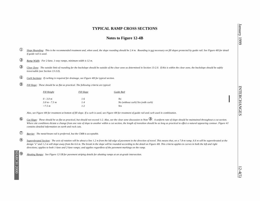
January 1999 IN
TERC
HA
NG
ES12-4(5)
TYPICAL RAMP CROSS SECTIONS
Notes to Figure 12-4B
ë Slope Rounding: This is the recommended treatment and, when used, the slope rounding should be 2.4 m. Rounding is not necessary on fill slopes protected by guide rail. See Figure 4H for detailif guide rail is used.
ì Ramp Width: For 2-lane, 1-way ramps, minimum width is 12 m.
í Clear Zone: The outside limit of rounding for the backslope should be outside of the clear zone as determined in Section 13-2.0. If this is within the clear zone, the backslope should be safelytraversable (see Section 13-3.0).
î Curb Sections: If curbing is required for drainage, see Figure 4H for typical section.
ï Fill Slope: These should be as flat as practical. The following criteria are typical:
Fill Height Fill Slope Guide Rail
0 - 3.0 m 1:6 No3.0 m - 7.5 m 1:4 No (without curb) Yes (with curb)>7.5 m 1:2 Yes
Also, see Figure 4H for treatment at bottom of fill slope. If a curb is used, see Figure 4H for treatment of guide rail and curb used in combination.
ð Cut Slope: These should be as flat as practical, but should not exceed 1:2. Also, see the clear zone discussion in Note í. A uniform rate of slope should be maintained throughout a cut section.Where site conditions dictate a change from one rate of slope to another within a cut section, the length of transition should be as long as practical to effect a natural appearing contour. Figure 4Jcontains detailed information on earth and rock cuts.
ñ Barrier: The metal-beam rail is preferred, but the CMB is acceptable.
ò Superelevated Section: The axis of rotation will be about a line 1.2 m from the left edge of pavement in the direction of travel. This means that, on a 7.8-m ramp, 6.6 m will be superelevated at thedesign "e" and 1.2 m will slope away from the 6.6 m. The break in the slope will be rounded according to the detail on Figure 4H. This criteria applies to curves in both the left and rightdirections; applies to both 1-lane and 2-lane ramps; and applies regardless of the pavement markings on the ramp.
ó Abutting Ramps: See Figure 12-5B for pavement striping details for abutting ramps at an at-grade intersection.
MA
RC
H 2000

12-4(6) INTERCHANGES January 1999
MARCH 2000
L = (e) (W) (P)
where: L = superelevation transition length (m)P = 100e = superelevation rate (expressed as a decimal)W = width of pavement rotation (m)
c. The axis of rotation will be about a line 1.2 m from the inside edge of pavement. Thismeans that, on a 7.8-m ramp, 6.6 m will be superelevated at the design "e" and 1.2 mwill slope away from the 6.6-m section. The break in the slope will be roundedaccording to the detail on Figures 4H and 5J. This criteria applies to curves in boththe left and right directions and applies regardless of the pavement markings on theramp.
d. The designer should not superelevate curves on ramps such that the design "e" ismaintained on the curve for a very short distance. No specific minimum length isprovided; these will be evaluated on a case-by-case basis.
e. If the ramp will be terminated at an at-grade intersection with stop or signal control,it is not appropriate to fully superelevate curves near the terminal.
6. Sight Distance. Section 8-2.04 describes how to determine the middle ordinate to providestopping sight distance at horizontal curves.
12-4.04 Vertical Alignment
Maximum grades for vertical alignment cannot be as definitively expressed as those for the highwaymainline. General values of limiting gradient are shown in Figure 12-4C, but for any one ramp theselected gradient is dependent upon a number of factors. These factors include the following:
1. The flatter the gradient on the ramp relative to the freeway grade, the longer it will be. Atrestricted sites, it may be necessary to provide a steeper grade for the purpose of shorteningthe length of ramp.
2. The steepest gradients should be designed for the center part of the ramp. Landing areas orstorage platforms at at-grade intersections should be as flat as practical.
3. Downgrades on ramps should follow the same guidelines as upgrades. They may, however,safely exceed these values by 2%, with 8% considered a recommended maximum.
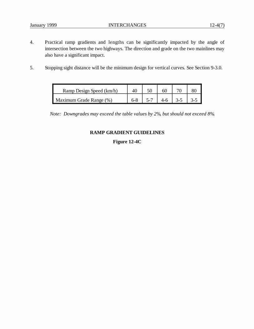
January 1999 INTERCHANGES 12-4(7)
4. Practical ramp gradients and lengths can be significantly impacted by the angle ofintersection between the two highways. The direction and grade on the two mainlines mayalso have a significant impact.
5. Stopping sight distance will be the minimum design for vertical curves. See Section 9-3.0.
Ramp Design Speed (km/h) 40 50 60 70 80
Maximum Grade Range (%) 6-8 5-7 4-6 3-5 3-5
Note: Downgrades may exceed the table values by 2%, but should not exceed 8%.
RAMP GRADIENT GUIDELINES
Figure 12-4C

12-4(8) INTERCHANGES January 1999
January 1999 INTERCHANGES 12-5(1)
12-5.0 RAMP/CROSSING ROAD INTERSECTION
12-5.01 Design of At-Grade Intersections
Where the ramp will intersect the minor road at-grade, this intersection should be treated asdescribed in Chapter Eleven. This will involve a consideration of capacity and the physical geometricdesign elements such as design vehicle, sight distance, angle of intersection, acceleration lanes,grade, channelization and turning lanes. However, several points warrant special attention in thedesign of the ramp/crossing road intersection:
1. Capacity. In urban areas where traffic volumes are often high, inadequate capacity of theramp/crossing road intersection can adversely affect the operation of the ramp/freewayjunction. In a worst case situation the safety and operation of the mainline itself may beimpaired by a backup onto the freeway. Therefore, special attention should be given toproviding sufficient capacity and storage for an at-grade intersection or merge with thecrossing road. This could lead to the addition of lanes at the intersection or on the rampproper (see Figure 12-5A), or it could involve traffic signalization where the ramp traffic willbe given priority. The analysis must also consider the operational impacts of the trafficcharacteristics in either direction on the intersecting road. Coordinate this analysis with theDivision of Traffic Engineering. See Chapter 11 for additional information.
2. Sight Distance. Section 11-2.0 discusses the criteria for intersection sight distance. Thesecriteria also apply to a ramp/crossing road intersection. Special attention must be given to thelocation of the bridge pier or abutment because these will present major sight distanceobstacles. The bridge obstruction and the required intersection sight distance may result inthe need to relocate the ramp/crossing road intersection.
3. Wrong-Way Movements. Most wrong-way movements originate at the ramp/crossing roadintersection. This intersection must be properly signed and designed to minimize the potentialfor a wrong-way movement.
4. Abutting Ramps. Figure 12-4B illustrates the use of a metal-beam rail to divide abuttingramps. This provides a physical separation and discourages wrong-way entry. Where theramp intersects the crossing road, the median barrier should be terminated with an approvedend terminal. Where a median barrier is not used, the abutting ramps should intersect theminor road as shown in Figure 12-5B.
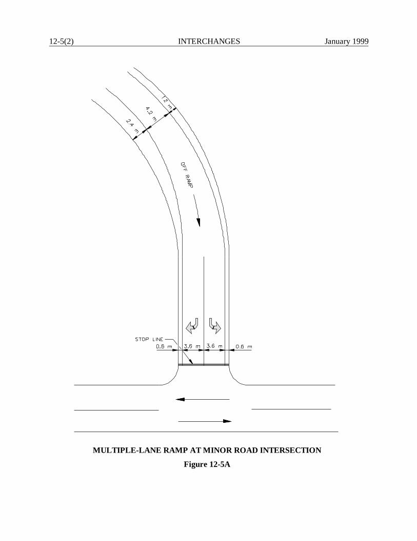
12-5(2) INTERCHANGES January 1999
MULTIPLE-LANE RAMP AT MINOR ROAD INTERSECTION
Figure 12-5A
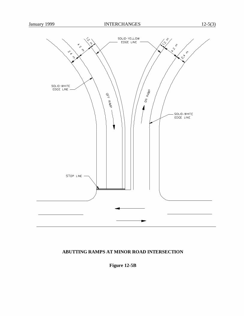
January 1999 INTERCHANGES 12-5(3)
ABUTTING RAMPS AT MINOR ROAD INTERSECTION
Figure 12-5B
12-5(4) INTERCHANGES January 1999
12-5.02 Frontage Road Intersection
Where frontage roads are present adjacent to freeways, the ramp/crossing road intersection is greatlycomplicated. If practical, the frontage road should be curved away from the interchange and allowedto intersect the minor road a sufficient distance from the ramp intersection. If the ramp intersects thecrossing road at approximately 90o, this distance should be at least 90 m. If the ramp traffic mergeswith the crossing road, the distance should be 90 m beyond where the taper of the acceleration laneends. This treatment allows the two intersections to operate independently, and it eliminates theoperational and signing problems of providing the same point of exit and entrance for the frontageroad and freeway ramp.
At some interchanges, it may be impractical to separate the intersections of the ramp and frontageroad with the crossing road. In these cases, the only alternative is to combine the ramp and frontageroad before the intersection with the crossing road. This can apply to either the exit or entranceramp. A detailed analysis will be necessary to establish the needed distance to properlyaccommodate traffic volumes and speeds, weaving, stopping and intersection storage. Coordinatethis analysis with the Division of Traffic Engineering.
12-5.03 Access Control
Proper access control must be provided along the crossing road in the vicinity of the ramp/crossingroad intersection. This will ensure that the intersection has approximately the same degree offreedom and absence of conflict as the freeway itself. Figure 12-5C illustrates the Department'spolicy for the location of the non-access line at ramp/crossing road intersections. Any proposalswhich do not meet these criteria will require an exception to the controlling design criteria. SeeSection 6-6.0. This applies to all of the access control criteria in Figure 12-5C. This also applies bothto new interchanges and to existing non-access lines at existing interchanges.
One situation warrants a special discussion. Many interchanges were initially constructed inConnecticut when the surrounding area was rural in character. Since that time, the area may havebecome suburban or urban. As indicated in Figure 12-5C, the Department has adopted differentcriteria for the access control at urban and rural interchanges. However, the change in area characteralone is not a sufficient justification to alter the location of the non-access line.

January 1999 INTERCHANGES 12-5(5)
NON-ACCESS LINE TREATMENT IN VICINITY OF RAMP TERMINAL
Figure 12-5C

12-5(6) INTERCHANGES January 1999
January 1999 INTERCHANGES 12-6(1)
12-6.0 REFERENCES
1. A Policy on Geometric Design of Highways and Streets, AASHTO, 1994.
2. Highway Capacity Manual, TRB, 1994.
3. NCHRP 345, Single Point Urban Interchange Design and Operations Analysis, TRB, 1991.
4. NCHRP 175, Freeway Lane Drops, TRB, 1976.

12-6(2) INTERCHANGES January 1999
January 1999 ROADSIDE SAFETY 13-i
Chapter Thirteen
ROADSIDE SAFETY
Table of Contents
Page
13-1.01 DEFINITIONS . . . . . . . . . . . . . . . . . . . . . . . . . . . . . . . . . . . . . . . . . . . 13-1(1)
13-2.0 CLEAR ZONES . . . . . . . . . . . . . . . . . . . . . . . . . . . . . . . . . . . . . . . . . . . 13-2(1)
13-2.01 Background . . . . . . . . . . . . . . . . . . . . . . . . . . . . . . . . . . . . . . . . . 13-2(1)13-2.02 Application . . . . . . . . . . . . . . . . . . . . . . . . . . . . . . . . . . . . . . . . . 13-2(1)13-2.03 Rock Removal . . . . . . . . . . . . . . . . . . . . . . . . . . . . . . . . . . . . . . . 13-2(6)13-2.04 Utility Setback and Design Exceptions Procedures . . . . . . . . . . . . 13-2(7)
13-3.0 GUIDE RAIL WARRANTS . . . . . . . . . . . . . . . . . . . . . . . . . . . . . . . . . . . . . 13-3(1)
13-3.01 Embankments . . . . . . . . . . . . . . . . . . . . . . . . . . . . . . . . . . . . . . . 13-3(1)13-3.02 Roadside Hazards . . . . . . . . . . . . . . . . . . . . . . . . . . . . . . . . . . . . 13-3(1)13-3.03 Bridge Rails and Approaches . . . . . . . . . . . . . . . . . . . . . . . . . . . . 13-3(3)13-3.04 Bridge Piers & Abutments . . . . . . . . . . . . . . . . . . . . . . . . . . . . . . 13-3(3)13-3.05 Vertical Drop-offs . . . . . . . . . . . . . . . . . . . . . . . . . . . . . . . . . . . . 13-3(3)13-3.06 Roadside Ditches, Channels and Swales . . . . . . . . . . . . . . . . . . . . 13-3(6)
13-3.07 Transverse Slopes . . . . . . . . . . . . . . . . . . . . . . . . . . . . . . . . . . . . 13-3(6)13-3.08 High Tension Lines and Reservoirs . . . . . . . . . . . . . . . . . . . . . . . . 13-3(9)
13-4.0 ROADSIDE BARRIERS . . . . . . . . . . . . . . . . . . . . . . . . . . . . . . . . . . . . . . . 13-4(1)
13-4.01 Guide Rail Types . . . . . . . . . . . . . . . . . . . . . . . . . . . . . . . . . . . . . 13-4(1)
13-4.01.01 Three Cable Guide Railing (I-Beam Posts) . . . . . . . 13-4(1) 13-4.01.02 Metal Beam Rail (Type R-I) . . . . . . . . . . . . . . . . . 13-4(3)
13-4.01.03 Metal Beam Rail (Type R-B) . . . . . . . . . . . . . . . . . 13-4(3)13-4.01.04 Metal Beam Rail (Type R-B 350) . . . . . . . . . . . . . 13-4(3)
13-4.01.05 Thrie Beam 350 . . . . . . . . . . . . . . . . . . . . . . . . . . . 13-4(4)13-4.01.06 Metal Beam Rail (Box Beam) . . . . . . . . . . . . . . . . 13-4(4)13-4.01.07 Single-Faced Precast Concrete Barrier Curb
(PCBC) . . . . . . . . . . . . . . . . . . . . . . . . . . . . . . . . 13-4(4)13-4.01.08 Merritt Parkway Timber Rail . . . . . . . . . . . . . . . . . 13-4(4)
13-ii ROADSIDE SAFETY January 1999
Table of Contents(Continued)
Page
13-4.02 Deflection Distance . . . . . . . . . . . . . . . . . . . . . . . . . . . . . . . . . . 13-4(5)
13-4.03 Disposition of Existing Guide Rail . . . . . . . . . . . . . . . . . . . . . . 13-4(8)
13-4.03.01 NHS Facilities . . . . . . . . . . . . . . . . . . . . . . . . . . 13-4(8)13-4.03.02 All Other Facilities . . . . . . . . . . . . . . . . . . . . . . . 13-4(8)
13-5.0 MEDIAN BARRIERS . . . . . . . . . . . . . . . . . . . . . . . . . . . . . . . . . . . . . . 13-5(1)
13-5.01 Warrants . . . . . . . . . . . . . . . . . . . . . . . . . . . . . . . . . . . . . . 13-5(1)13-5.02 Median Barrier Types . . . . . . . . . . . . . . . . . . . . . . . . . . . . . . . . 13-5(1)
13-5.02.01 Metal Beam Rail (Type MD-I) . . . . . . . . . . . . . 13-5(1)13-5.02.02 Metal Beam Rail (Type MD-B) . . . . . . . . . . . . . 13-5(3)13-5.02.03 Metal Beam Rail (Type MD-B 350) . . . . . . . . . 13-5(3)13-5.02.04 Double-Faced F-Shape PCBC . . . . . . . . . . . . . . 13-5(3)13-5.02.05 Merritt Parkway Median Barrier . . . . . . . . . . . . 13-5(3)
13-5.03 Median Barrier Placement . . . . . . . . . . . . . . . . . . . . . . . . . . . . . 13-5(4)
13-5.03.01 Divided Median Barriers . . . . . . . . . . . . . . . . . . 13-5(6)
13-5.04 Glare Screens . . . . . . . . . . . . . . . . . . . . . . . . . . . . . . . . . . . . . . 13-5(6)13-5.05 Disposition of Existing Median Barriers . . . . . . . . . . . . . . . . . . 13-5(7)
13-5.05.01 NHS Facilities . . . . . . . . . . . . . . . . . . . . . . . . . . 13-5(7)13-5.05.02 All Other Facilities . . . . . . . . . . . . . . . . . . . . . . . 13-5(7)
13-6.0 GUIDE RAIL LAYOUT . . . . . . . . . . . . . . . . . . . . . . . . . . . . . . . . . . . . . . 13-6(1)
13-6.01 Length of Need . . . . . . . . . . . . . . . . . . . . . . . . . . . . . . . . . . . . . . 13-6(1)13-6.02 Flare Rate . . . . . . . . . . . . . . . . . . . . . . . . . . . . . . . . . . . . . . . . . 13-6(1)13-6.03 Lateral Placement . . . . . . . . . . . . . . . . . . . . . . . . . . . . . . . . . . . . 13-6(1)13-6.04 Curbs and Curb/Barrier Combinations . . . . . . . . . . . . . . . . . . . 13-6(3)13-6.05 Placement on Slopes . . . . . . . . . . . . . . . . . . . . . . . . . . . . . . . . . 13-6(4)13-6.06 Minimum Length and Guide Rail Gaps . . . . . . . . . . . . . . . . . . . 13-6(5)13-6.07 Treatment at Intersecting Roads and Driveways . . . . . . . . . . . . 13-6(5)13-6.08 Guide Rail Curvature Criteria . . . . . . . . . . . . . . . . . . . . . . . . . . 13-6(7)

January 1999 ROADSIDE SAFETY 13-iii
Table of Contents(Continued)
Page
13-6.09 Transitions . . . . . . . . . . . . . . . . . . . . . . . . . . . . . . . . . . . . . . . . . 13-6(7)
13-6.09.01 Transitions Within Same Type System . . . . . . . . 13-6(7) 13-6.09.02 Transitions Between Systems . . . . . . . . . . . . . . . 13-6(8)
13-6.10 Pavement for Railing . . . . . . . . . . . . . . . . . . . . . . . . . . . . . . . . . 13-6(8)13-6.11 Placement on High Fills with Sidewalk and Utility Pole Lines . 13-6(10)
13-7.0 IMPACT ATTENUATORS . . . . . . . . . . . . . . . . . . . . . . . . . . . . . . . . . . . . 13-7(1)
13-7.01 General . . . . . . . . . . . . . . . . . . . . . . . . . . . . . . . . . . . . . . 13-7(1)
13-7.01.01 Definitions . . . . . . . . . . . . . . . . . . . . . . . . . . . . . 13-7(1)13-7.01.02 Crash Cushion and End Terminal Types . . . . . . 13-7(2)13-7.01.03 Crash Cushion Selection . . . . . . . . . . . . . . . . . . 13-7(2)13-7.01.04 Crash Cushion Design . . . . . . . . . . . . . . . . . . . . 13-7(2)
13-7.02 End Treatment Selection . . . . . . . . . . . . . . . . . . . . . . . . . . . . . . 13-7(4)
13-7.02.01 End Treatment Design . . . . . . . . . . . . . . . . . . . . 13-7(4)13-7.02.02 Three Cable Guide Rail . . . . . . . . . . . . . . . . . . . 13-7(6)13-7.02.03 Merritt Parkway . . . . . . . . . . . . . . . . . . . . . . . . . 13-7(6)13-7.02.04 Metal Beam Rail Median Barrier (Type MD-B350) 13-7(6)13-7.02.05 Concrete Median Barrier . . . . . . . . . . . . . . . . . . 13-7(6)
13-8.0 REFERENCES . . . . . . . . . . . . . . . . . . . . . . . . . . . . . . . . . . . . . . . . . . . 13-8(1)
APPENDIX
Guide Rail Procedure
FHWA Technical Advisory T5040.32 “Curved W-Beam GuardrailInstallations at Minor Roadway Intersections”

13-iv ROADSIDE SAFETY January 1999

January 1999 ROADSIDE SAFETY 13-1(1)
Chapter ThirteenROADSIDE SAFETY
This Chapter provides the designer with guidance on measures to reduce the number and/or severityof accidents when vehicles leave the traveled way.
The "forgiving roadside" concept, developed in the 1960's, has been a long-standing philosophy inConnecticut. As a result, many of ConnDOT's State highways have been constructed to meet thisdesign philosophy. In addition, guidance for installing roadside safety hardware has graduallyevolved to reflect the results of crash test programs.
The American Association of State Highway and Transportation Officials (AASHTO) hasincorporated many of the crash test results and roadside safety design concepts into the RoadsideDesign Guide (RDG). ConnDOT's Manual for Selecting, Locating and Designing Guide Railingand Traffic Barriers has been replaced by the RDG.
Chapter Thirteen is a supplement to the RDG. Where there is a discrepancy between the two,Chapter Thirteen will take precedence.
13-1.0 DEFINITIONS
1. Recoverable Parallel Slope. Slopes which can be safely traversed and upon which the driverof an errant vehicle has a reasonable opportunity to stop and return to the roadway. TheDepartment considers slopes flatter than 1:4 and slopes of 1:4 without curbing at their toprecoverable.
2. Non-Recoverable Parallel Slope. Slopes which are steeper than 1:4. Most drivers will not beable to recover and return to the highway. The Department has decided to treat this rangeof cross slopes as critical.
3. Critical Parallel Slope. Slopes upon which a vehicle is likely to overturn. Under theDepartment’s roadside criteria, slopes steeper than 1:4 and slopes of 1:4 with curbing at thetop are critical.
These definitions vary slightly from those in the RDG.

13-1(2) ROADSIDE SAFETY January 1999
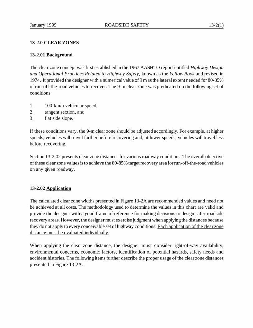
January 1999 ROADSIDE SAFETY 13-2(1)
13-2.0 CLEAR ZONES
13-2.01 Background
The clear zone concept was first established in the 1967 AASHTO report entitled Highway Designand Operational Practices Related to Highway Safety, known as the Yellow Book and revised in1974. It provided the designer with a numerical value of 9 m as the lateral extent needed for 80-85%of run-off-the-road vehicles to recover. The 9-m clear zone was predicated on the following set ofconditions:
1. 100-km/h vehicular speed,2. tangent section, and3. flat side slope.
If these conditions vary, the 9-m clear zone should be adjusted accordingly. For example, at higherspeeds, vehicles will travel farther before recovering and, at lower speeds, vehicles will travel lessbefore recovering.
Section 13-2.02 presents clear zone distances for various roadway conditions. The overall objectiveof these clear zone values is to achieve the 80-85% target recovery area for run-off-the-road vehicleson any given roadway.
13-2.02 Application
The calculated clear zone widths presented in Figure 13-2A are recommended values and need notbe achieved at all costs. The methodology used to determine the values in this chart are valid andprovide the designer with a good frame of reference for making decisions to design safer roadsiderecovery areas. However, the designer must exercise judgment when applying the distances becausethey do not apply to every conceivable set of highway conditions. Each application of the clear zonedistance must be evaluated individually.
When applying the clear zone distance, the designer must consider right-of-way availability,environmental concerns, economic factors, identification of potential hazards, safety needs andaccident histories. The following items further describe the proper usage of the clear zone distancespresented in Figure 13-2A.
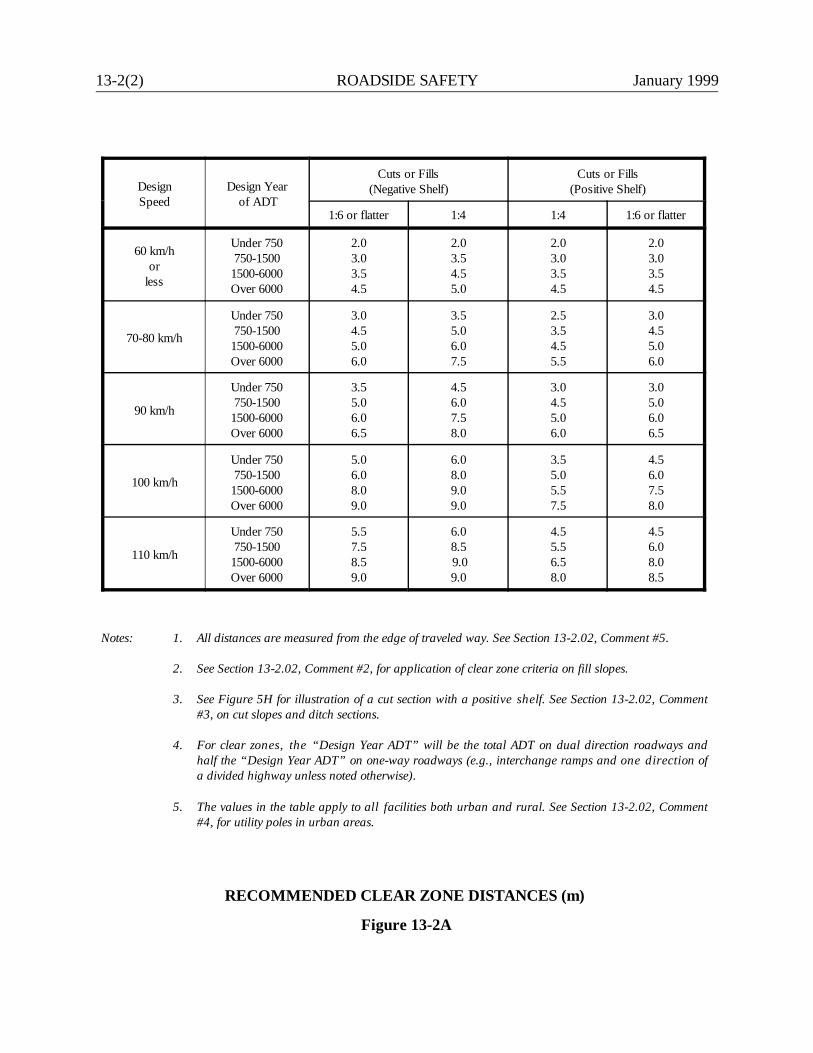
13-2(2) ROADSIDE SAFETY January 1999
DesignSpeed
Design Year of ADT
Cuts or Fills(Negative Shelf)
Cuts or Fills(Positive Shelf)
1:6 or flatter 1:4 1:4 1:6 or flatter
60 km/hor
less
Under 750750-1500
1500-6000Over 6000
2.03.03.54.5
2.03.54.55.0
2.03.03.54.5
2.03.03.54.5
70-80 km/h
Under 750750-1500
1500-6000Over 6000
3.04.55.06.0
3.55.06.07.5
2.53.54.55.5
3.04.55.06.0
90 km/h
Under 750750-1500
1500-6000Over 6000
3.55.06.06.5
4.56.07.58.0
3.04.55.06.0
3.05.06.06.5
100 km/h
Under 750750-1500
1500-6000Over 6000
5.06.08.09.0
6.08.09.09.0
3.55.05.57.5
4.56.07.58.0
110 km/h
Under 750750-1500
1500-6000Over 6000
5.57.58.59.0
6.08.5 9.09.0
4.55.56.58.0
4.56.08.08.5
Notes: 1. All distances are measured from the edge of traveled way. See Section 13-2.02, Comment #5.
2. See Section 13-2.02, Comment #2, for application of clear zone criteria on fill slopes.
3. See Figure 5H for illustration of a cut section with a positive shelf. See Section 13-2.02, Comment#3, on cut slopes and ditch sections.
4. For clear zones, the “Design Year ADT” will be the total ADT on dual direction roadways andhalf the “Design Year ADT” on one-way roadways (e.g., interchange ramps and one direction ofa divided highway unless noted otherwise).
5. The values in the table apply to all facilities both urban and rural. See Section 13-2.02, Comment#4, for utility poles in urban areas.
RECOMMENDED CLEAR ZONE DISTANCES (m)
Figure 13-2A
January 1999 ROADSIDE SAFETY 13-2(3)
1. Boundaries. The designer should not use the clear zone distances as boundaries forintroducing roadside hazards such as bridge piers, non-breakaway sign supports or utilitypoles. These should be placed as far from the roadway as practical. Where roadside hazardsmust be placed along the highway, at a minimum they should be placed at the clear zoneboundary and possibly shielded.
2. Fill Slopes. Figure 13-2A provides clear zone values as a function of design speed, trafficvolume, and the rate of fill slopes with a positive or negative shelf. Figure 13-2B illustratesthe clear zone application on fill slopes with a negative shelf. Barn-roof fill slopes may bedesigned with two slope rates where the second slope is steeper than the slope adjacent tothe shoulder. See Figure 13-2B(b). This design requires less right-of-way and embankmentmaterial than a continuous, flatter slope. Although a “weighted” average of the slopes maybe used, a simple average of the clear zone distances for each slope is sufficiently accurateif the variable slopes are approximately the same width. If one slope is significantly wider,the clear zone computation based on that slope alone may be used.
3. Cut Slopes. Figure 13-2A also provides clear zone values as a function of design speed,traffic volume, and the rate of cut slopes with a positive or negative shelf. Figure 13-2Cillustrates the clear zone application in a cut section. The designer must also referenceSection 13-3.06 for guidance on the proper treatment of drainage features encounteredwithin the clear zone.
The outside limit of rounding for the backslope should be outside of the clear zone. This isillustrated in the typical section figures in Chapters Four and Five. When this is notachievable, the following approach should be used to calculate the clear zone for a ditchsection:
a. When the backslope is 1:6 or flatter, treat the backslope as level and use the clearzone for the front slope.
b. When the backslope is between 1:6 and 1:4, assume the vehicle cannot make it upto the top of the backslope, if the slope is at least 3-m wide. The initial 3 m beyondthe toe of the backslope or the distance in Step #3a, whichever is less, should be clearof roadside hazards. Any obstacles beyond this point would be considered outside ofthe clear zone.
c. When the backslope is steeper than 1:4, assume the vehicle cannot make it up thebackslope. However, the initial 1.5 m beyond the outside limit of rounding for thebackslope should be clear of roadside hazards. Any obstacles beyond 1.5 m wouldbe considered outside of the clear zone.

13-2(4) ROADSIDE SAFETY January 1999
CLEAR ZONE APPLICATION FOR FILL SLOPES(Negative Shelf)
Figure 13-2B

January 1999 ROADSIDE SAFETY 13-2(5)
CLEA RZONE A
PPLICATION FOR CUT SLOPES
Figure 13-2C
13-2(6) ROADSIDE SAFETY January 1999
4. Urban Facilities. A minimum horizontal obstruction-free clearance of 500 mm should beprovided as measured from the gutter line to any utility pole, sign or traffic signal pole. Clearzones to other fixed objects such as buildings should conform to Figure 13-2A. Refer to theUtility Setback and Design Exceptions Procedure in Section 13-2.04.
5. Auxiliary Lanes. For auxiliary lanes, such as climbing lanes, passing lanes, etc., the clearzone will be the same as for the mainline and will be measured from the outside edge of theauxiliary lane. The clear zone will not normally apply to left- and right-turning lanes atintersections. When evaluating cross-over accident potential for undivided roadways, theclear zone will be measured from the left edge of the through travelway.
6. Horizontal Curves. Additional clear zone may be provided on the outside of horizontal curvesby the use of curve correction factors that are included in the RDG. These increases shouldbe considered only where accident histories indicate a need or where specific investigationsindicate a high potential for accidents and where the increase to the clear zone is costeffective.
13-2.03 Rock Removal
Because of the often considerable expense in removing rock to meet roadside clear zone criteria, theDepartment adopted a policy specifically for rock removal. If the costs and associated impacts withremoving rock to meet the clear zone criteria in Figure 13-2A are reasonable, the designer shouldmeet these criteria. If, however, there are significant negative impacts and/or the costs are major,the designer should evaluate the following factors:
1. Other Benefits. The rock removal may generate benefits other than those for roadside safety.These include:
a. improving intersection sight distance;b. improving sight distance around horizontal curves; orc. improving any rock stability, ground water and/or icing problems.
Any additional benefits should be considered when determining the extent of the rockremoval.
2. Alternative Improvements. Where the designer determines that retaining the rock within theclear zone presents a significant roadside hazard, the designer should consider alternativeimprovements to rock removal. These include:
January 1999 ROADSIDE SAFETY 13-2(7)
a. installing a single-faced concrete barrier or guide rail, and
b. providing a positive slope (with rounding at its toe) up to the face of the rock (1:4 orsteeper) to provide limited vehicular redirection.
3. Application. If rock is within the clear zone and more than 5.5 m from the edge of traveledway, the ConnDOT Design Exception Committee will review the case and will either:
a. determine that rock removal is appropriate because of its accident potential, or b. grant a waiver of the clear zone criteria.
Designers should also discern whether or not the rock is in a condition that may imperil thetraveling public by flaking, falling or icing. If so, the designer should evaluate the need forand proper type of roadside barrier protection. This should be documented in the project fileand verification sought from the Design Exception Committee.
13-2.04 Utility Setback and Design Exceptions Procedures
There will be many sites where it will be impractical to locate utility poles outside the clear zone fora project. This is especially prevalent in urban projects but could apply to any project, dependingupon the circumstances.
This discussion provides the requirements for blanket design exceptions for utility poles locatedwithin the clear zone. Provided the criteria noted below is complied with and the utility companyhas justified, to the satisfaction of the Department, that its poles have been set back to the maximumextent practical, waivers will not have to be approved through the Design Exception Committee.
The project correspondence file should provide sufficient documentation that utility poles are setback in accordance with the criteria. It is suggested that the request for design approval include thefollowing information:
1. Utility poles should be positioned outside the clear zone whenever practical.
2. A maximum utility pole setback of 3.0 m (measured from the outside edge of the shoulderor the gutter line), irrespective of the clear zone, is permissible. This setback dimension isconsistent with the capabilities of the utility company’s installation and maintenanceequipment. The maximum 3.0-m setback is also consistent with the utility company’scorporate strategy of providing a quick response to power outages, etc.
13-2(8) ROADSIDE SAFETY January 1999
3. The Department may require a setback greater than 3.0 m up to a maximum of 9.0 m ifconditions such as, but not limited to, a higher incidence of accidents related to the presenceof utility poles exist.
4. Along urban highways, the Department will require poles to be placed as close to the right-of-way line as practical. Where sufficient space is available, poles must be placed in backof the sidewalk. If insufficient space is available, the Department may allow poles to beplaced between the curb and sidewalk or as far from the curb as practical when there are nosidewalk considerations (minimum 500 mm behind the face of curb).
5. Design exceptions for utility poles within the clear zone are still required when it is theDepartment’s position that the utility company is not locating its poles in accordance withthese criteria.
January 1999 ROADSIDE SAFETY 13-3(1)
13-3.0 GUIDE RAIL WARRANTS
Determining the need for guide rail can be difficult and time consuming. Existing conditions maylimit the designer's options thus increasing project cost, environmental impacts and right-of-wayacquisitions. However, when economically and practically feasible, the designer should alwaysattempt to eliminate the need for guide rail.
Section 1.2 of the RDG provides the designer with six design options, in order of priority, forredesigning the roadside to eliminate the need for guide rail. These steps should become an integralpart of the preliminary design phase of all Department projects where applicable.
The following sections illustrate where guide rail may be warranted.
13-3.01 Embankments
The severity of the roadside condition depends upon the rate and height of the fill slope. Refer toFigure 13-3A for Comparative Risk Warrants for Embankments. This figure is revised from Figure5.1 of the RDG. Depending on the height of fill slope, guide rail may be needed to shield a fill slopesteeper than 1:4 and slopes of 1:4 with curbing. See section 13-6.04 for curb and curb/barriercombinations. Guide rail is not required on fill slopes flatter than 1:4 if there are no roadside hazardswithin the clear zone as calculated from Section 13-2.0.
13-3.02 Roadside Hazards
The recommended clear zone distances for various roadway conditions presented in Section 13-2.0should be free of any fixed objects and non-traversable hazards. Roadside hazards that may warrantguide rail include but are not limited to the following:
1. non-breakaway sign and luminaire supports,2. concrete bases extending more than 100 mm above the ground,3. bridge piers and abutments at underpasses,4. retaining walls and culvert end-walls,5. trees with diameter greater than 150 mm (at maturity),6. rough rock cuts,7. large boulders,8. streams or permanent bodies of water,9. stone fences, and10. utility poles. Note: It is not Department policy to design guide rail to protect the traveling
public from utility poles.
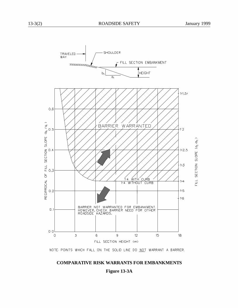
13-3(2) ROADSIDE SAFETY January 1999
COMPARATIVE RISK WARRANTS FOR EMBANKMENTS
Figure 13-3A
January 1999 ROADSIDE SAFETY 13-3(3)
These hazards in some instances may not warrant guide rail depending on their location. Forexample, to install guide rail to protect an errant vehicle from an isolated tree at the edge of a 9-mclear zone may not be practical.
The designer should recognize that even barriers installed to deflect errant vehicles away from fixedobjects may be hazards themselves. Preference should therefore be given to eliminating or relocatingthe fixed object or potential hazard rather than placing guide rail in front of it whenever possible.
13-3.03 Bridge Rails and Approaches
The leading and trailing ends of bridge rails normally warrant protection. The highway designer isresponsible for determining the need for and design of the guide rail leading up to and trailing fromthe bridge rail; the bridge designer is responsible for the design of the bridge rail and details for guiderail attachment to bridge parapets. Figure 13-3B illustrates warrants for providing guide railapproaching a bridge rail. Refer to the Department’s Guide Rail Procedure for the disposition ofexisting leading end transitions to bridge parapets. Section 13-6.09.02 provides additionalinformation on transitions.
13-3.04 Bridge Piers & Abutments
Bridge piers and abutments should normally be placed outside the clear zone. However, many ofConnecticut's existing bridge piers and abutments are within the design clear zone and can not berelocated and, therefore, warrant guide rail protection. Where full-height abutments are immediatelyoutside the clear zone, a leading end guide rail treatment may often be warranted.
When the face of existing bridge piers and abutments are less than or equal to 1 m from the edge ofroadway, the selected system must meet appropriate deflection requirements. Section 13-4.02provides more information on the deflection parameters for various guide rail types.
13-3.05 Vertical Drop-Offs
An extended length of vertical drop-off, either along a fill slope or at the shoulder edge (e.g.,retaining wall), typically warrants the installation of an unyielding barrier (e.g., concrete medianbarrier) when the height of the vertical drop-off is 800 mm or greater. The single-faced, pre-castconcrete barrier curb should not be used unless the area behind it can be backfilled. Normally, eitherthe full-section pre-cast concrete barrier curb or a cast-in-place retaining wall is used. Figure 13-3Cprovides additional details on where an unyielding barrier may be required.
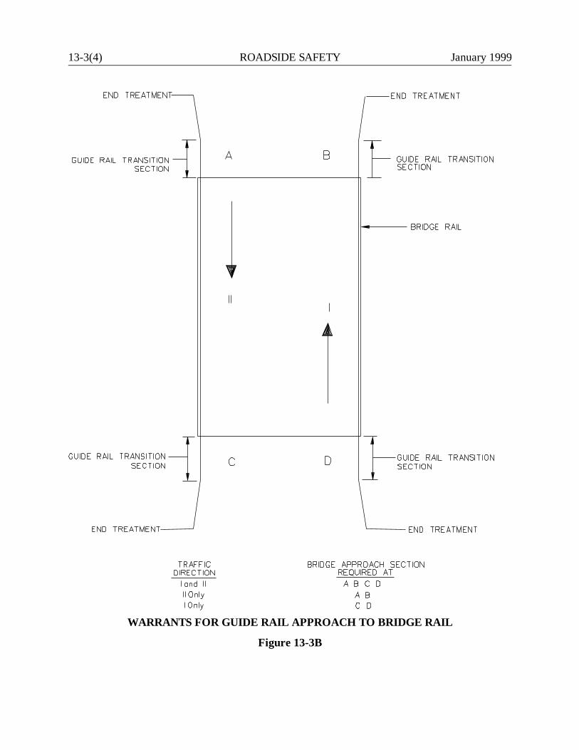
13-3(4) ROADSIDE SAFETY January 1999
WARRANTS FOR GUIDE RAIL APPROACH TO BRIDGE RAIL
Figure 13-3B
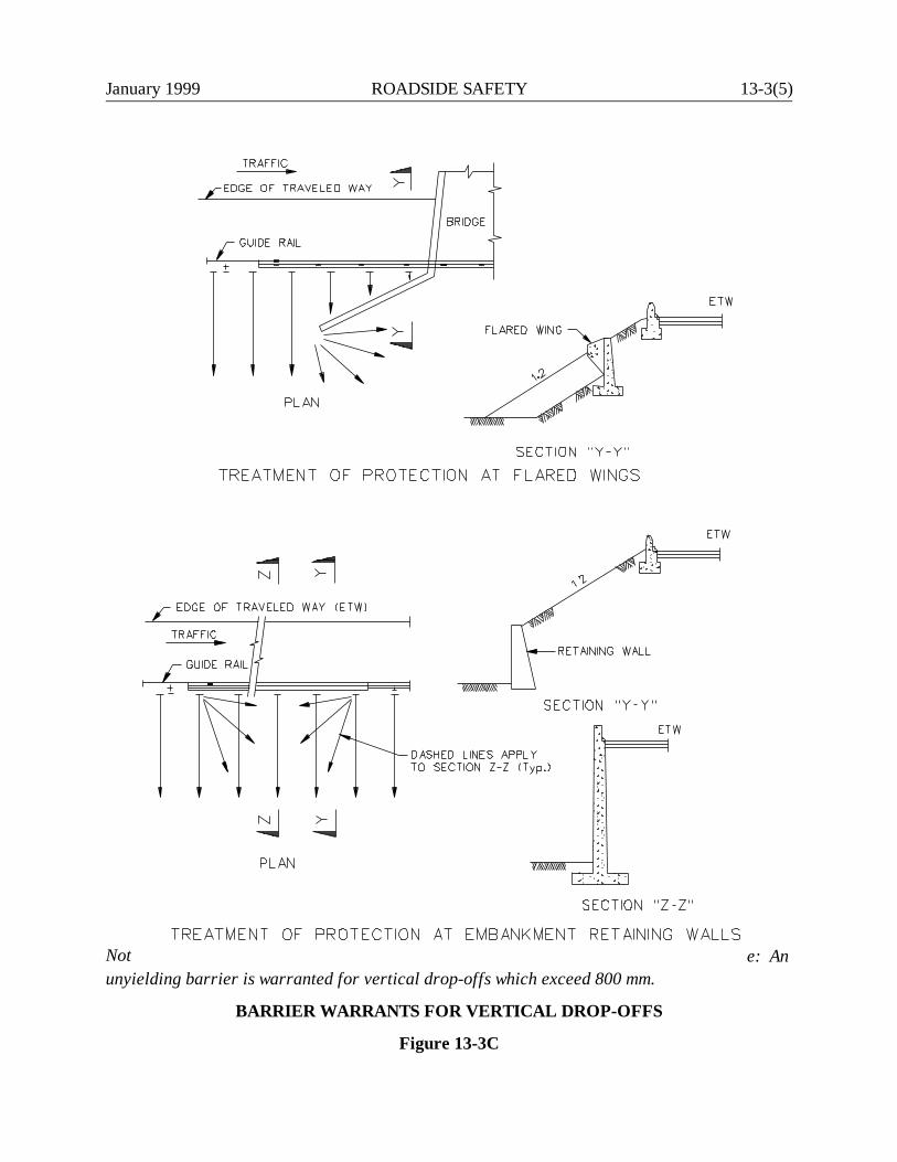
January 1999 ROADSIDE SAFETY 13-3(5)
Not e: Anunyielding barrier is warranted for vertical drop-offs which exceed 800 mm.
BARRIER WARRANTS FOR VERTICAL DROP-OFFS
Figure 13-3C
13-3(6) ROADSIDE SAFETY January 1999
13-3.06 Roadside Ditches, Channels and Swales
If a vehicle departs the roadway and encounters ditches, channels or swales, the roadsideconfiguration may introduce abrupt changes in vehicular direction which can result in destabilizationof the vehicle. Figure 13-3D illustrates the relative traversability of various combinations of frontslopes, ditch widths and backslopes for roadside channels, ditches and swales.
The typical section figures in Chapters Four and Five and Figure 13-2C illustrate the standardroadside swales in a cut section. For highways without curbs, the front slope is 1:12, the roundedditch width is 3 m and the backslope is variable but not to exceed 1:2. The typical sections also showthat the outside limit of rounding for the backslope should be outside the clear zone distancedetermined from Section 13-2.0. Where this limit is within the clear zone, the designer shouldattempt to relocate the outside limit of rounding to beyond the clear zone.
Ditch sections that fall within Zone 1 in Figure 13-3D may warrant guide rail. However, the designershould consider the cost effectiveness of installing lengthy sections of guide rail to shield a ditch.This is not always desirable and may warrant revising the ditch cross section to eliminate the needfor guide rail.
If the dimensions of an existing or proposed ditch section fall within Zone 2 in Figure 13-3D, thebackslope should be flattened if practical. If this is not feasible, guide rail is not warranted becauseof the ditch cross section alone. In this Zone, guide rail is considered more of a hazard than the ditchitself and, therefore, may not be warranted.
13-3.07 Transverse Slopes
Where the highway mainline intersects a driveway, side road or median crossing, a slope transverseto the mainline will be present. See Figure 13-3E. If the guide rail is impacted by a run-off-the-roadvehicle at this location, the angle of impact will likely be close to 90 degrees. Even for relatively flatside slopes, this may result in vehicular vaulting; for steeper slopes the vehicular bumper may"catch" in the slope resulting in an abrupt stop and high occupant accelerations.
For these reasons, transverse slopes should be as flat as practical. For design speeds of 80 km/h orhigher, the slope should be 1:12 typical or 1:10 maximum or flatter. Below 80 km/h, the slope shouldbe 1:6 or flatter. If this criteria cannot be met practically, guide rail may be considered. The decisionto use guide rail should be made on a case-by-case basis considering costs, traffic volumes, severityof the proposed transverse slope and other relevant factors. If guide rail is needed around the cornersof intersecting roads or driveways, see Figure 13-6D for placement criteria on radii and AppendixA for design criteria of the "Washington Curved Guide rail Treatment".
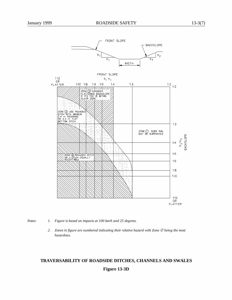
January 1999 ROADSIDE SAFETY 13-3(7)
Notes: 1. Figure is based on impacts at 100 km/h and 25 degrees.
2. Zones in figure are numbered indicating their relative hazard with Zone ë being the mosthazardous.
TRAVERSABILITY OF ROADSIDE DITCHES, CHANNELS AND SWALES
Figure 13-3D
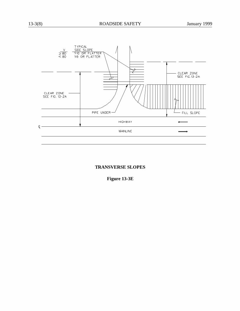
13-3(8) ROADSIDE SAFETY January 1999
TRANSVERSE SLOPES
Figure 13-3E
January 1999 ROADSIDE SAFETY 13-3(9)
JUNE 1999
13-3.08 High Tension Lines and Reservoirs
A 1145-mm precast or cast-in-place concrete barrier curb with the F-shape or box beam are thepreferred means of shielding high tension line towers and water supply reservoirs. See Section 13-4.0for a description of the box beam and Section 13-5.0 for a description of the F-shape roadsidebarrier.

13-3(10) ROADSIDE SAFETY January 1999
January 1999 ROADSIDE SAFETY 13-4(1)
13-4.0 ROADSIDE BARRIERS
FHWA has mandated that as of October 1, 1998 all new installations of roadside safety hardwareon the National Highway System (NHS) must meet, at a minimum, Test Level 3 (TL-3) crash testingcriteria in National Cooperative Highway Research Program (NCHRP) Report 350 RecommendedProcedures for the Safety Performance Evaluation of Highway Features. This applies to roadsidebarriers (i.e., guide rail), impact attenuators, end treatments, bridge rails and guide rail-to-bridge-railtransitions. The Department has adopted the TL-3 criteria as the minimum acceptable for newinstallations on all State-owned highways, whether on or off the NHS. Unless indicated otherwise,all guide rail types in Section 13-4.01 have met the TL-3 criteria in NCHRP Report 350.
13-4.01 Guide Rail Types
Figure 13-4A presents the Department’s preferred guide rail systems. The figure summarizes thehardware requirements for each system. The designer should reference the Connecticut StandardSheets for detailed information on each system. The following sections describe each system and itstypical usage. In addition, several special roadside guide rails are described.
13-4.01.01 Three Cable Guide Railing (I-Beam Posts)
Three cable guide railing is a weak-post flexible system with a large dynamic deflection. Most of theresistance to impact is supplied by the tensile forces developed in the cable strands. Upon impact,the cables break away from the posts, and the vehicle is able to knock down the posts as it isredirected by the cables. The detached posts do not contribute to controlling the lateral deflection.However, the posts which remain in place do provide a substantial part of the lateral resistance tothe impacting vehicle and are therefore critical to proper performance.
Three cable guide railing is the most forgiving of the available systems because of its large dynamicdeflection. It should only be used where considerable lengths of the proper deflection distance isavailable behind the guide rail. Its use should be tempered by the following considerations:
1. Transitions. Do not use three cable guide railing for leading end transitions into bridge rails.
2. Slopes. Do not use three cable guide railing on fill slopes steeper than 1:2, unless the distancebetween the back of the posts and the break in the fill slope is at least 2.4 m.

13-4(2)R
OA
DSID
E SAFETY
January 1999
TypeThree CableGuide Rail
Metal Beam Rail(Type R-B 350)
Merritt ParkwayGuide Rail
AASHTO Designation SGR01a SGR04a (Modified) N/A
General Type Weak-post (flexible) Strong-post (semi-rigid) Strong-post (semi-rigid)
Standard Post Spacing 4900 mm 1905 mm 3050 mm
Max. Dynamic Deflection 3.3 m 1.305 m 1.305 m
Post Type S75 x 8.5 Steel W150 x 13.5 Steel W150 x 22.5 Steel
Beam TypeThree 19-mm dia. SteelCables
Steel W. Section150 mm x 300 mm RoughSawn Timber
Offset Brackets None150 mm x 200 mm x 330 mmRecycled Plastic Block Out
100 mm x 200 mm x 275 mmTimber Block Out
Note: Recycled plastic block outs approved by FHWA per NCHRP Report 350 TL-3 criteria shall be used with R-B 350 guide railsystems. See Connecticut Standard Sheets. The Merritt Parkway Guide Rail is approved for use solely on the Merritt Parkway(see Section 13-4.01.08).
January 1999 ROADSIDE SAFETY 13-4(3)
3. Minimum Radius. Three cable guide railing shall not be used on radii less than or equal to135 m. See Figure 13-6E for guide rail curvature criteria.
4. Cable Tension. For three cable guide rail to provide full impact performance, the cables mustbe tensioned properly. Therefore, maintenance forces should ensure that the cable strandsare tensioned properly at all times.
13-4.01.02 Metal Beam Rail (Type R-I)
Like three cable guide railing, the metal beam rail (Type R-I) is a weak-post flexible system. Thetensile strength in the longitudinal W-beam will provide most of the resistance to the lateral forcesof the impacting vehicle.
The Type R-I guide rail failed the TL-3 crash testing criteria in NCHRP Report 350. As a result,Department policy is that no new installations of this system will be allowed on any State-ownedroadway. See Appendix A for latest Guide Rail Procedure.
13-4.01.03 Metal Beam Rail (Type R-B)
The metal beam rail (Type R-B) is a strong post semi-rigid system with steel posts and steel blockouts. The Type R-B guide rail failed the TL-3 crash testing criteria in NCHRP Report 350. As aresult, Department policy is that no new installations of this system will be allowed on any State-owned roadway. See Appendix A for latest Guide Rail Procedure.
13-4.01.04 Metal Beam Rail (Type R-B 350)
After the failure of metal beam rail (Type R-B) with steel block outs, FHWA tested a similar systemwith timber block outs that passed TL-3. Further tests were performed using recycled plastic blockouts that passed TL-3 and were approved by FHWA. The Department has decided to use onlyrecycled plastic block outs with FHWA approval for R-B 350 and MD-B 350 guide rail.
The maximum dynamic deflection of R-B 350 guide rail is much less than that of three cable guiderail. The deceleration forces on vehicle occupants when impacting R-B 350 are significantly higherthan impacts with three cable guide rail. Thus, three cable guide rail is the preferred system.However, R-B 350 guide rail has significant maintenance advantages over the flexible rail. It canoften safely sustain a second impact even after a major first impact. For this reason, R-B 350 guiderail should be strongly considered where a site has a history of frequent run-off-the-road accidentsor where the greater deflection distance required for three cable guide rail is not available or is onlyavailable intermittently.
13-4(4) ROADSIDE SAFETY January 1999
13-4.01.05 Thrie Beam 350
The Thrie Beam 350 passed the TL-3 crash test criteria in NCHRP Report 350. It is a strong postsemi-rigid guide rail with a 508-mm wide thrie-beam section, a W150 x 13.5 steel post, and a M369x 26 steel block out with a notch cut out of the bottom of the web. This rail has a maximum dynamicdeflection of 1.02 m at a 1905-mm post spacing. It may be used at selected sites on a case-by-casebasis with approval of the Transportation Engineering Administrator.
13-4.01.06 Metal Beam Rail (Box Beam)
The box beam rail passed the TL-3 crash test criteria in NCHRP Report 350. It is a weak post semi-rigid guide rail with a S75 x 8 steel post and a TS152 x 152 x 4.8 steel box rail. This rail has amaximum dynamic deflection of 1.15 m at a 1830-mm post spacing. It may be used at selected siteson a case-by-case basis with approval of the Transportation Engineering Administrator.
13-4.01.07 Single-Faced Precast Concrete Barrier Curb (PCBC)
ConnDOT previously used the "Jersey Shape" PCBC. The Department’s choice, when installing newpermanent PCBC, is the 1145-mm "F-shape". The single faced F-shape PCBC may be used on theroadside in front of rigid objects where no deflection distance is available. If the rigid object is notcontinuous (e.g., bridge piers), the designer should backfill behind the PCBC.
Existing "Jersey Shape" PCBC may remain. However, designers should provide a proper transitionwhere new construction meets existing. Refer to the Connecticut Standard Sheets for transitiondetails.
13-4.01.08 Merritt Parkway Timber Rail
The Merritt Parkway steel-backed timber guide rail combines aesthetic appeal (i.e., the timberlongitudinal member) with acceptable safety performance (i.e., it passed the TL-3 crash testingcriteria in NCHRP Report 350). The Department has approved this rail for use solely on the MerrittParkway. However aesthetically appealing, this rail has a high maintenance and installation costwhich precludes its widespread application on other State-owned roadways.
13-4.02 Deflection Distance
January 1999 ROADSIDE SAFETY 13-4(5)
The "deflection distance" is defined as the lateral distance that the outside (side away from traffic)face of a barrier will deflect when struck by an errant vehicle before that barrier system stops themovement away from the road. Deflection for heavy post systems is measured as the deflection fromthe outside face of the posts to the hazard. This distinction is made because weak post rail systemsusually separate from the posts when struck, while heavy post systems will usually remain attached.The clear distance to an obstruction must therefore include an allowance for the width of the heavypost. This clear distance for deflection is determined by the vehicular weight, speed, angle of impactand strength or rigidity of the barrier system.
The deflection distance is an important parameter for two reasons. First, it determines the magnitudeof the lateral deceleration. Rigid systems, such as concrete barriers, produce essentiallyinstantaneous lateral decelerations which are more likely to result in injuries. This difference is themajor safety factor favoring the selection of flexible systems. The second reason that deflectiondistance is important is that it determines the space that must be maintained between the hazard andthe barrier. If a hazard is allowed to remain or grow within the deflection distance of a barrier, thelongitudinal movement of an errant vehicle can still carry it into the obstacle, even if the lateralmovement has been arrested. The results of crash tests have been analyzed to develop a method forestimating the deflections that may be expected when a standard 2000-kg vehicle strikes differenttypes of barriers at different speeds and impact angles.
Figure 13-4D presents the deflection distances expected when various barrier systems are impactedat 100 km/h with a standard 2000-kg vehicle at 25 degrees. Vehicles traveling at lower speeds onnarrow roadways with reduced lateral offsets tend to impact guide rail at smaller angles therebycreating a smaller deflection in the guide rail. For this reason, Figure 13-4B is used when needed todetermine the maximum lateral offset for narrow roads. Figure 13-4C should be used to establishapplicable reduction factors that may be used to decrease the normal dynamic deflection of guiderail when proposed for installation on lower speed, narrow roadways. Refer to the example problemin Figure 13-4C.
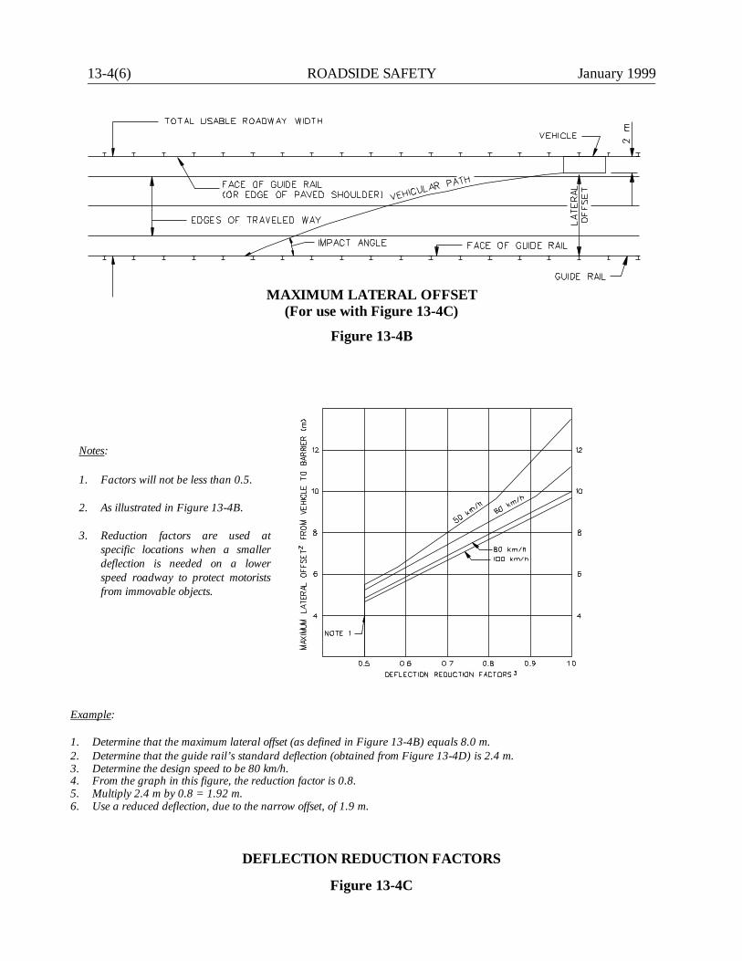
13-4(6) ROADSIDE SAFETY January 1999
Notes:
1. Factors will not be less than 0.5.
2. As illustrated in Figure 13-4B.
3. Reduction factors are used atspecific locations when a smallerdeflection is needed on a lowerspeed roadway to protect motoristsfrom immovable objects.
Example:
1. Determine that the maximum lateral offset (as defined in Figure 13-4B) equals 8.0 m.2. Determine that the guide rail’s standard deflection (obtained from Figure 13-4D) is 2.4 m.3. Determine the design speed to be 80 km/h.4. From the graph in this figure, the reduction factor is 0.8.5. Multiply 2.4 m by 0.8 = 1.92 m.6. Use a reduced deflection, due to the narrow offset, of 1.9 m.
MAXIMUM LATERAL OFFSET(For use with Figure 13-4C)
Figure 13-4B
DEFLECTION REDUCTION FACTORS
Figure 13-4C
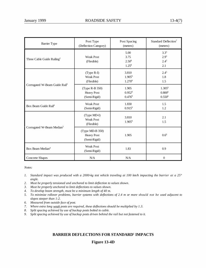
January 1999 ROADSIDE SAFETY 13-4(7)
Barrier TypePost Type
(Deflection Category)Post Spacing
(meters)Standard Deflection7
(meters)
Three Cable Guide Railing2 Weak Post(Flexible)
5.003.752.508
1.258
3.35
2.95
2.45
2.1
Corrugated W-Beam Guide Rail3
(Type R-I)Weak Post(Flexible)
3.8101.9059
1.2709
2.45
1.8 1.5
(Type R-B 350)Heavy Post(Semi-Rigid)
1.9050.9529
0.4769
1.3056
0.8006 0.5506
Box Beam Guide Rail4 Weak Post(Semi-Rigid)
1.8300.9159
1.51.2
Corrugated W-Beam Median3
(Type MD-I)Weak Post(Flexible)
3.8101.9059
2.11.5
(Type MD-B 350)Heavy Post(Semi-Rigid)
1.905 0.66
Box Beam Median4 Weak Post(Semi-Rigid)
1.83 0.9
Concrete Shapes N/A N/A 0
Notes:
1. Standard impact was produced with a 2000-kg test vehicle traveling at 100 km/h impacting the barrier at a 25°angle.
2. Must be properly tensioned and anchored to limit deflection to values shown.3. Must be properly anchored to limit deflections to values shown.4. To develop beam strength, must be a minimum length of 40 m.5. To minimize rollover problems, barrier systems with deflections of 2.4 m or more should not be used adjacent to
slopes steeper than 1:2.6. Measured from outside face of post.7. Where extra long weak posts are required, these deflections should be multiplied by 1.3.8. Split spacing achieved by use of backup posts bolted to cable.9. Split spacing achieved by use of backup posts driven behind the rail but not fastened to it.
BARRIER DEFLECTIONS FOR STANDARD1 IMPACTS
Figure 13-4D
13-4(8) ROADSIDE SAFETY January 1999
Department policy for selecting guide rail with respect to deflection needs is summarized below:
1. The barrier system with the largest acceptable deflection should be selected when a barrier isrequired.
2. The deflection of the selected system must be less than the distance from the line of the barrierto the nearest hazard that cannot be removed or relocated.
3. All removable hazards must be removed from the area within the deflection distance of theselected guide rail. Maintenance work may be needed to prevent trees within the deflectiondistance from growing to more than 100 mm in diameter. Because the Department cannot controldevelopment beyond the right-of-way (ROW) line, the selection of a barrier system should ensurethat its deflection will not extend beyond the ROW.
13-4.03 Disposition of Existing Guide Rail
13-4.03.01 NHS Facilities
Refer to the latest Guide Rail Procedure in Appendix A for disposition of existing guide rail systems onNHS facilities and the Merritt Parkway.
13-4.03.02 All Other Facilities
It is Department policy that all future and existing roadside safety hardware meet the crash testingrequirements presented in NCHRP Report 350. Therefore, when any of the longitudinal barriers listed inthe Guide Rail Procedure mentioned in Appendix A are encountered within the limits of a project, designersshould upgrade the guide rail to the new standards.
January 1999 ROADSIDE SAFETY 13-5(1)
13-5.0 MEDIAN BARRIERS
13-5.01 Warrants
The following summarizes the Department's criteria:
1. Freeways. Median barrier is warranted on all medians of 20.1 m or less. A median barriermay also be warranted on wider medians if a significant number of accidents have occurred.
Medians may vary in width. If a section warrants a median barrier but a wider section doesnot, the barrier should be extended into the wider median by approximately 30 m.
2. Non-Freeways. On lower-speed, lower-class highways, some judgment must be used. Onhighways without access control, the median barrier must terminate at each at-gradeintersection, which is undesirable. In addition, lower speeds will reduce the likelihood of acrossover accident. On non-freeways, the designer should evaluate the accident history,traffic volumes, travel speeds, median width, alignment, sight distance and construction coststo determine an appropriate median barrier.
13-5.02 Median Barrier Types
All new installations of median barrier on NHS roadways must meet the TL-3 crash testing criteriain NCHRP Report 350. Figure 13-5A presents the types of median barriers which are typically usedby the Department. The figure summarizes the hardware requirements for each system. Unlessindicated otherwise, all types have met TL-3 criteria in NCHRP Report 350. Section 13-5.03provides additional guidance on the selection of median barriers.
13-5.02.01 Metal Beam Rail (Type MD-I)
Metal beam rail (Type MD-I) is a weak-post flexible median barrier. Its performance is similar tometal beam rail (Type R-I). FHWA has tested Type R-I guide rail at TL-3 and it failed. As a result,corresponding median Type MD-I has also been deemed a failure. Therefore, Department policy isthat no new installations of this system will be allowed on any State-owned roadway.
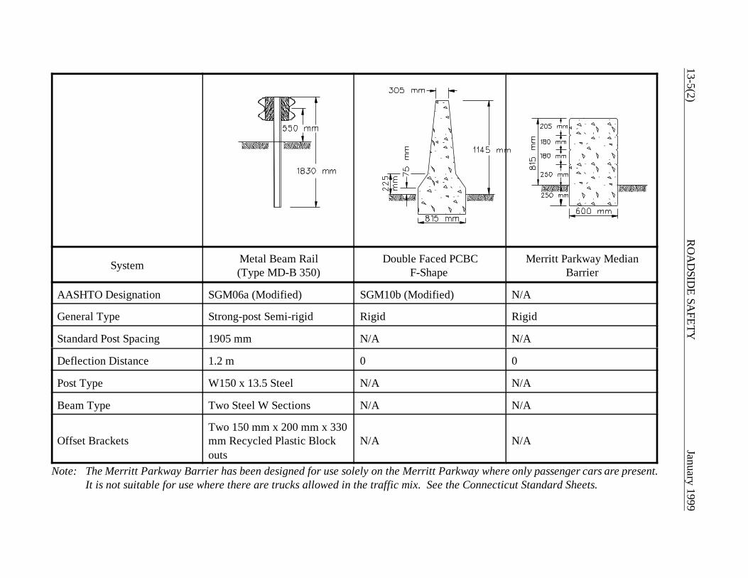
13-5(2)R
OA
DSID
E SAFETY
January 1999
System Metal Beam Rail(Type MD-B 350)
Double Faced PCBCF-Shape
Merritt Parkway MedianBarrier
AASHTO Designation SGM06a (Modified) SGM10b (Modified) N/A
General Type Strong-post Semi-rigid Rigid Rigid
Standard Post Spacing 1905 mm N/A N/A
Deflection Distance 1.2 m 0 0
Post Type W150 x 13.5 Steel N/A N/A
Beam Type Two Steel W Sections N/A N/A
Offset BracketsTwo 150 mm x 200 mm x 330mm Recycled Plastic Blockouts
N/A N/A
Note: The Merritt Parkway Barrier has been designed for use solely on the Merritt Parkway where only passenger cars are present.It is not suitable for use where there are trucks allowed in the traffic mix. See the Connecticut Standard Sheets.
January 1999 ROADSIDE SAFETY 13-5(3)
13-5.02.02 Metal Beam Rail (Type MD-B)
Metal beam rail (Type MD-B) is a strong-post semi-rigid system with steel posts and steel block outs.Its performance is similar to metal beam rail (Type R-B). FHWA has tested Type R-B guide rail atTL-3 and it failed. As a result, corresponding median Type MD-B has also been deemed a failure.Therefore, Department policy is that no new installations of this guide rail will be allowed on anyState-owned roadway.
13-5.02.03 Metal Beam Rail (Type MD-B 350)
Metal beam rail (Type MD-B 350) is a strong-post semi-rigid median barrier with steel posts andrecycled plastic block outs. Its performance is similar to metal beam rail Type R-B 350. MD-B 350median guide rail is most applicable in medians with narrow or intermediate widths on non-freeways.One special application for MD-B 350 is to separate adjacent on/off ramps at interchanges.
13-5.02.04 Double-Faced F-Shape PCBC
As discussed in Section 13-4.01.07, the Department’s choice for new permanent median PCBC isthe 1145-mm F-shape. See the latest Guide Rail Policy and Procedure in Appendix A. When installing median PCBC, the distance between the edge of traveled way and the concretemedian barrier should not exceed 3.6 m as illustrated in Figures 4I and 5K.
13-5.02.05 Merritt Parkway Median Barrier
Two individual roadside sections of the standard steel-backed timber guide rail discussed in Section13-4.01.08 may be used in the median on the Merritt Parkway when the median is greater than orequal to 4 m wide. Two individual roadside sections of System 2 or System 3 shown in theConnecticut Standard Sheets may be used when the median is between 2 m and 4 m wide. Ideally,designers should install the appropriate steel-backed timber guide rail system with the properdeflection needed for the site.
Where the median width is too narrow to accommodate the deflection of the steel-backed timberguide rail, the Merritt Parkway median barrier will be used. See the Connecticut Standard Sheetsfor more details on its use and placement.

13-5(4) ROADSIDE SAFETY January 1999
13-5.03 Median Barrier Placement
The ideal location for the median barrier is in the center of the median which will provide amaximum clear recovery area for each direction of travel. The presence of excessive slopes orexisting drainage in the center may make it impossible to locate a barrier there. Therefore, thefollowing criteria will apply:
1. Slopes. A median barrier should not be placed where the roadside slope up to the barrierexceeds 1:10. For a PCBC, the slope leading up to the barrier will be the shoulder slope.Existing median slopes greater than 1:10 should be flattened to a desirable 1:12 rate ormaximum 1:10 rate.
Figure 13-5B illustrates three basic types of sloped medians. The following discusses eachtype; it assumes a median barrier is warranted:
a. For Cross Section I, the designer should determine if the individual slopes warrantprotection based on the criteria in Section 13-3.0. If both slopes warrant protection(Illustration 1), guide rail should be placed at “b” and “d”. If one slope warrantsprotection, a median barrier should be placed to shield that slope. If neither slopewarrants protection and both slopes are steeper than 1:10 (Illustration 2), a medianbarrier should be placed at “b” or “d”, whichever is shielding the steeper slope. If theslopes are 1:10 or flatter (Illustration 3), the median barrier should be placed slightlyto one side of the center of the median so that it does not interfere with highwaydrainage.
b. For Cross Section II, the slope in the median will determine the proper treatment. Ifthe slope is between 1:10 and 1:4 (Illustration 4), the median barrier should be placedat “b.” If the median slope is 1:4 or steeper, guide rail at “b” is the only necessarytreatment. If the median slope is a roadside hazard (e.g., rough rock cut) (Illustration5), guide rail should be placed at both “b” and “d.” If the median slope is 1:10 orflatter (Illustration 6), the median barrier should be placed in the center of themedian.
c. For Cross Section III (Illustration 7), the redirective capacity of the median slope willdetermine the proper treatment. If the median slope is 1:4 or steeper and > 1 m invertical height, no roadside nor median barrier is necessary. If the median slopes areflatter than 1:4 and/or < 1 m in vertical height, the median barrier should be placedat the apex of the cross section.

January 1999 ROADSIDE SAFETY 13-5(5)
SLOPED MEDIANS
Figure 13-5B
13-5(6) ROADSIDE SAFETY January 1999
13-5.03.01 Divided Median Barriers
It may be necessary to intermittently divide a median barrier. The slope criteria in Section 13-5.03 or afixed object in the median may require this. The median barrier may be divided by one of these methods:
1. A fixed object may be encased by an F-shaped PCBC.
2. A single-faced F-shaped PCBC may be used on both sides to shield a fixed object. Backfillingmay be necessary.
3. Metal beam rail MD-B 350 may be split into two separate runs of guide rail passing on either sideof the median hazard (fixed object or slope).
If a median barrier is split, the design should adhere to the acceptable flare rates (Figure 13-6A). Wherepractical, the flare rate should be 50:1.
The designer should note that, when a vehicle impacts a PCBC, the vehicle may lean over the top of thebarrier and strike bridge piers, sign supports, light poles, etc., that have been placed on the top of thebarrier. If practical, fixed objects should be placed on the outside of the highway beyond the clear zone,instead of on top of the PCBC. Designers should refer to the Connecticut Standard Sheets for placementof PCBC's adjacent to bridge piers.
13-5.04 Glare Screens
Headlight glare from opposing traffic can be bothersome and distracting. Glare screens can be used incombination with median barriers to eliminate this problem. The Department has not adopted specificwarrants for the use of glare screens.
The typical application, however, is on urban freeways with narrow medians and high traffic volumes orbetween on/off ramps at interchanges where the two ramps adjoin each other. Here, the sharp radii ofcurvature and the narrow separation may make headlight glare especially bothersome. Designers shouldconsider the use of glare screens at these sites especially if the Department has received a significantnumber of public complaints.
Blocking headlight glare can be achieved in several ways:
1. Vegetation can be used; however, the designer should not introduce hazardous fixed objects in anarrow median.
January 1999 ROADSIDE SAFETY 13-5(7)
2. Several commercial glare screens are available. Considering both effectiveness and ease ofmaintenance, the paddle glare barrier may be the best choice. These are a series of plastic paddleswhich are usually mounted to a PCBC.
Glare screens should be designed for a cutoff angle of 20o. This is the angle between the median centerlineand the line of sight between two vehicles traveling in opposite directions. The glare screen should bedesigned to block the headlights of oncoming vehicles up to the 20o cutoff angle. On horizontal curves, thedesign cutoff angle should be increased to allow for the effect of the curvature on headlight direction. SeeFigure 13-5C. The criteria is:
Cutoff Angle = 20 + 1746.8/Rwhere R = Curve radius, m
The designer should also evaluate the impact of a glare screen on horizontal sight distance on curves to theleft. The screen could significantly reduce the available middle ordinate for stopping sight distance. SeeSection 8-2.0 for a discussion of sight distance at horizontal curves.
13-5.05 Disposition of Existing Median Barriers
13-5.05.01 NHS Facilities
Refer to the latest Guide Rail Procedure in Appendix A for disposition of existing median barriers on theNHS facilities and the Merritt parkway.
13-5.05.02 All Other Facilities
It is Department Policy that all future and existing roadside safety hardware meet the crash testingrequirements presented in NCHRP Report 350. Therefore, when any of the longtitudinal barriers listed inthe Guide Rail Procedure are encountered within the limits of a project, designers should upgrade the guiderail to the new standards.
Temporary median Jersey-shaped PCBC may continue to be used for maintenance and protection of trafficduring construction, provided that positive moment conection between barriers, as shown in theMiscellaneous Connecticut Details, is incorporated.
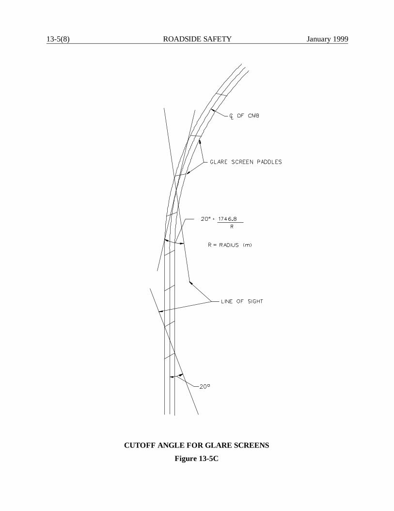
13-5(8) ROADSIDE SAFETY January 1999
CUTOFF ANGLE FOR GLARE SCREENS
Figure 13-5C
January 1999 ROADSIDE SAFETY 13-6(1)
13-6.0 GUIDE RAIL LAYOUT
13-6.01 Length of Need
The Department's criteria for determining the length of need is as follows:
1. Terminal Outside The Clear Zone. The Connecticut Standard Sheets illustrate the typicaltreatment for leading end anchors of R-B 350 or MD-B 350 guide rail placed outside theclear zone as determined from Section 13-2.0. Where this layout cannot be achieved, seeComment #2.
2. Terminal Within The Clear Zone. Designers should use Section 5.6.4 in the RDG todetermine the length of need for all leading ends of guide rail located within the clear zone.
13-6.02 Flare Rate
It may be necessary to laterally relocate a run of guide rail to terminate the end anchorage outsidethe clear zone or to meet a bridge parapet. This lateral relocation may increase the angle of impacton the guide rail. Therefore, guide rail flare rates should be based on Figure 13-6A.
13-6.03 Lateral Placement
Guide rail should be placed as far as practical from the edge of the traveled way. This will minimizethe chance that it will be struck. The following factors should be considered when determining guiderail lateral placement:
1. The dynamic deflection distance of the guide rail, as shown in Figure 13-4D, should be met.
2. At a minimum, 0.6 m should be provided between the back of the guide rail post and thebreak in the fill slope. This will provide the necessary soil resistance for the post. In addition,on fill slopes steeper than 1:2, three cable guide railing should not be installed unless thedistance between the back of the post and the break in the fill slope is at least 2.4 m.
3. Drivers tend to "shy" away from continuous longitudinal obstacles along the roadside, suchas guide rail. Therefore, the minimum lateral guide rail offset without curbing should bebased on Figure 13-6B.
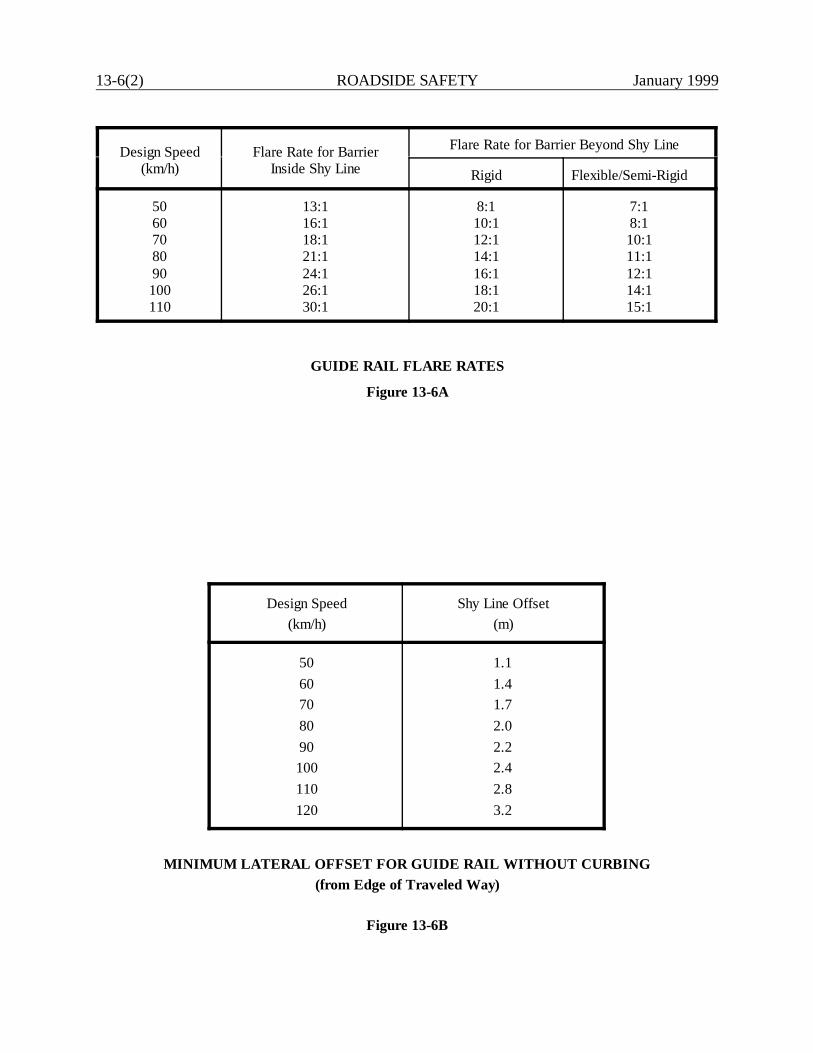
13-6(2) ROADSIDE SAFETY January 1999
Design Speed(km/h)
Flare Rate for BarrierInside Shy Line
Flare Rate for Barrier Beyond Shy Line
Rigid Flexible/Semi-Rigid
5060708090100110
13:116:118:121:124:126:130:1
8:110:112:114:116:118:120:1
7:18:110:111:112:114:115:1
GUIDE RAIL FLARE RATES
Figure 13-6A
Design Speed(km/h)
Shy Line Offset(m)
5060708090100110120
1.11.41.72.02.22.42.83.2
MINIMUM LATERAL OFFSET FOR GUIDE RAIL WITHOUT CURBING(from Edge of Traveled Way)
Figure 13-6B

January 1999 ROADSIDE SAFETY 13-6(3)
13-6.04 Curbs and Curb/Barrier Combinations
When the tires of an errant vehicle strike a curb, the impact tends to bounce the vehicle upwardswhich may contribute to vaulting or penetration of the rail. This problem is increased when curbs arelocated between 0.3 m and 3.0 m in front of guide rail. When the destabilizing or vertical bounce ofthe vehicle acts in combination with the longitudinal barrier, undesirable results may occur. Theplacement of curbing in conjunction with guide rail must be considered carefully.
The following criteria will apply for curb and curb/barrier combinations on high-speed (V> 80 km/h)roadways:
1. Curbing of any height is not permitted for use in conjunction with either concrete barriers orattenuating devices. Refer to Bridge Design for exceptions at abutments.
2. Curbing should not be used in gore areas or wide medians. Existing curbing should beremoved wherever practical.
3. When curbing is necessary for drainage control on high-speed roadways, a maximum heightof 100 mm may be used. W-beam guide rail will be installed with the face of the rail flushwith the face of the curbing and the height of the rail measured from the gutter line.However, where railing is behind a sidewalk, measure it from the top of the sidewalk. Seethe Connecticut Standard Sheets for 100-mm park curbing.
4. Curbing must not be placed along high-speed highways to shield pedestrians. Curbing isineffective as a barrier and, at high speeds, vehicles that contact curbing are at an increasedrisk of departing the traveled way and encroaching into areas frequented by pedestrians.
5. Due to the propensity for vehicles to vault or roll over W-beam guide rail when used withcurbing, the allowable guide rail deflection should not exceed 1.2 m.
6. Three cable guide rail when used with curbing shall be placed a maximum of 0.3 m fromthe face of curbing. The installation height will be measured from the top of pavement.
7. Refer to the Guide Rail Procedure and Connecticut Standard Sheets for transition curbingat bridge parapets.
The following criteria will apply to curb and curb/barrier combinations on low-speed (V @ 80 km/h)roadways:
1. Curbing of any height is not permitted for use in conjunction with either concrete barriers orattenuating devices. Refer to Bridge Design for exceptions at abutments.
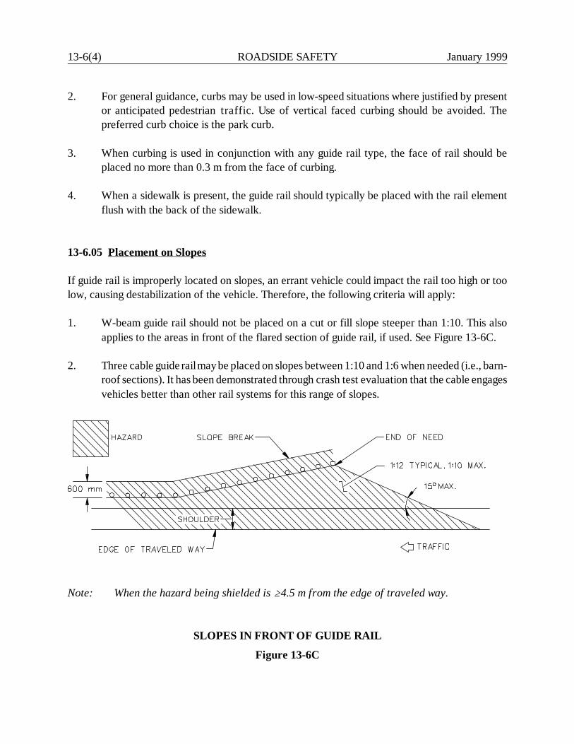
13-6(4) ROADSIDE SAFETY January 1999
2. For general guidance, curbs may be used in low-speed situations where justified by presentor anticipated pedestrian traffic. Use of vertical faced curbing should be avoided. Thepreferred curb choice is the park curb.
3. When curbing is used in conjunction with any guide rail type, the face of rail should beplaced no more than 0.3 m from the face of curbing.
4. When a sidewalk is present, the guide rail should typically be placed with the rail elementflush with the back of the sidewalk.
13-6.05 Placement on Slopes
If guide rail is improperly located on slopes, an errant vehicle could impact the rail too high or toolow, causing destabilization of the vehicle. Therefore, the following criteria will apply:
1. W-beam guide rail should not be placed on a cut or fill slope steeper than 1:10. This alsoapplies to the areas in front of the flared section of guide rail, if used. See Figure 13-6C.
2. Three cable guide rail may be placed on slopes between 1:10 and 1:6 when needed (i.e., barn-roof sections). It has been demonstrated through crash test evaluation that the cable engagesvehicles better than other rail systems for this range of slopes.
Note: When the hazard being shielded is A4.5 m from the edge of traveled way.
SLOPES IN FRONT OF GUIDE RAIL
Figure 13-6C
January 1999 ROADSIDE SAFETY 13-6(5)
13-6.06 Minimum Length and Guide Rail Gaps
Short runs of guide rail have limited value and should be avoided. As a general rule, the three cableguide railing should have at least 60 m of length at full height. Type R-B 350 guide rail should haveat least 26 m of length at full height. Likewise, short gaps between runs of guide rail are undesirable.In general, gaps less than 60 m between guide rail termini should be connected into a single run.However, this may not be possible on roadways with numerous driveway openings. Wheneverpossible, removal of the need for guide rail should be investigated to prevent short runs of guide railor multiple short gaps of guide rail.
13-6.07 Treatment at Intersecting Roads and Driveways
Guide rail runs on non-freeway facilities must often be interrupted by intersecting roads anddriveways. Figure 13-6D presents the typical treatment that should be used for terminating guide railat intersecting roads and driveways. When using this figure, the designer should consider thefollowing:
1. Studies have shown that there is an increased chance for vehicles to impact this type of guiderail installation at 90o. Because of the potential for high-angle impact, three cable guiderailing should not be used.
2. The guide rail should be flared away from the main road to allow sufficient sight distance forvehicles on the intersecting road or driveway.
3. The slope between the main line and the guide rail should not exceed 1:10.
4. The end treatments should meet the criteria in Section 13-7.0.
5. The designer should ensure that the treatment reflects the applicable safety considerationsfor the intersecting road or driveway.
6. On intersecting roads and driveways with design speeds of V @ 80 km/h, designersshould investigate the possibility of using the "Washington Curved Guide Rail Treatment."Refer to Appendix A for design criteria and the Connecticut Standard details.
7. Curbing should not be used in the area where guide rail is flared for the sight line.
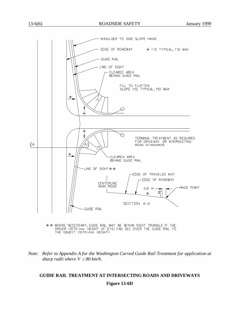
13-6(6) ROADSIDE SAFETY January 1999
Note: Refer to Appendix A for the Washington Curved Guide Rail Treatment for application atsharp radii where V @ 80 km/h.
GUIDE RAIL TREATMENT AT INTERSECTING ROADS AND DRIVEWAYS
Figure 13-6D
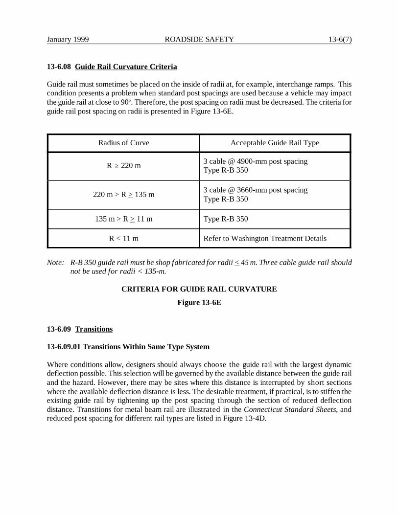
January 1999 ROADSIDE SAFETY 13-6(7)
13-6.08 Guide Rail Curvature Criteria
Guide rail must sometimes be placed on the inside of radii at, for example, interchange ramps. Thiscondition presents a problem when standard post spacings are used because a vehicle may impactthe guide rail at close to 90o. Therefore, the post spacing on radii must be decreased. The criteria forguide rail post spacing on radii is presented in Figure 13-6E.
Radius of Curve Acceptable Guide Rail Type
R A 220 m 3 cable @ 4900-mm post spacingType R-B 350
220 m > R > 135 m 3 cable @ 3660-mm post spacingType R-B 350
135 m > R > 11 m Type R-B 350
R < 11 m Refer to Washington Treatment Details
Note: R-B 350 guide rail must be shop fabricated for radii < 45 m. Three cable guide rail shouldnot be used for radii < 135-m.
CRITERIA FOR GUIDE RAIL CURVATURE
Figure 13-6E
13-6.09 Transitions
13-6.09.01 Transitions Within Same Type System
Where conditions allow, designers should always choose the guide rail with the largest dynamicdeflection possible. This selection will be governed by the available distance between the guide railand the hazard. However, there may be sites where this distance is interrupted by short sectionswhere the available deflection distance is less. The desirable treatment, if practical, is to stiffen theexisting guide rail by tightening up the post spacing through the section of reduced deflectiondistance. Transitions for metal beam rail are illustrated in the Connecticut Standard Sheets, andreduced post spacing for different rail types are listed in Figure 13-4D.
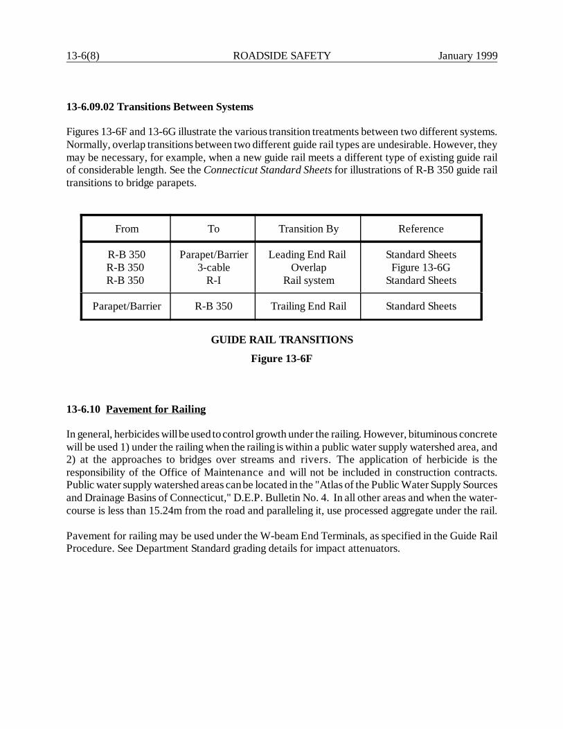
13-6(8) ROADSIDE SAFETY January 1999
13-6.09.02 Transitions Between Systems
Figures 13-6F and 13-6G illustrate the various transition treatments between two different systems.Normally, overlap transitions between two different guide rail types are undesirable. However, theymay be necessary, for example, when a new guide rail meets a different type of existing guide railof considerable length. See the Connecticut Standard Sheets for illustrations of R-B 350 guide railtransitions to bridge parapets.
From To Transition By Reference
R-B 350R-B 350 R-B 350
Parapet/Barrier3-cable
R-I
Leading End Rail Overlap
Rail system
Standard SheetsFigure 13-6G
Standard Sheets
Parapet/Barrier R-B 350 Trailing End Rail Standard Sheets
GUIDE RAIL TRANSITIONS
Figure 13-6F
13-6.10 Pavement for Railing
In general, herbicides will be used to control growth under the railing. However, bituminous concretewill be used 1) under the railing when the railing is within a public water supply watershed area, and2) at the approaches to bridges over streams and rivers. The application of herbicide is theresponsibility of the Office of Maintenance and will not be included in construction contracts.Public water supply watershed areas can be located in the "Atlas of the Public Water Supply Sourcesand Drainage Basins of Connecticut," D.E.P. Bulletin No. 4. In all other areas and when the water-course is less than 15.24m from the road and paralleling it, use processed aggregate under the rail.
Pavement for railing may be used under the W-beam End Terminals, as specified in the Guide RailProcedure. See Department Standard grading details for impact attenuators.
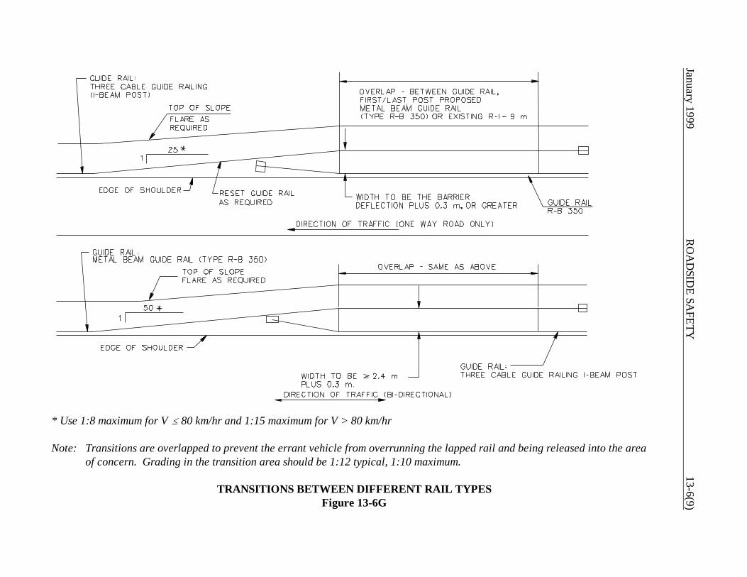
January 1999R
OA
DSID
E SAFETY
13-6(9)
* Use 1:8 maximum for V @ 80 km/hr and 1:15 maximum for V > 80 km/hr
Note: Transitions are overlapped to prevent the errant vehicle from overrunning the lapped rail and being released into the areaof concern. Grading in the transition area should be 1:12 typical, 1:10 maximum.
TRANSITIONS BETWEEN DIFFERENT RAIL TYPESFigure 13-6G
13-6(10) ROADSIDE SAFETY January 1999
13-6.11 Placement on High Fills with Sidewalk and Utility Pole Lines.
Theoretically, the preferred location for guide rail is behind the sidewalk with the utility pole linelocated at the guide rail deflection distance plus 0.3 m. In most locations, the pole would then beplaced at least five meters from the edge of the roadway. This is beyond the practical distance forwhich utility lines can be easily maintained and would increase the likelihood of the lines being tooclose to buildings. In practice, the utility poles will usually be placed within a utility strip/snow shelfbetween the street and the sidewalk. In high-speed areas where there are few driveway breaksrequiring guide rail between the street and the walk, consideration should be given to placing the railadjacent to the curb and the utility poles immediately behind the walk. See Utility Pole PlacementPolicy in Section 13-2.04.

January 1999 ROADSIDE SAFETY 13-7(1)
13-7.0 IMPACT ATTENUATORS
13-7.01 General
Impact attenuators may be categorized as either inertial or compression systems. Inertial systems aredesigned to transfer the kinetic energy of a vehicle to a series of yielding masses. Sand barrel arraysare a typical example. Compression systems are designed to absorb the energy of the vehicle by theprogressive deformation or crushing of the elements of the system. W-beam end terminals are atypical example.
13-7.01.01 Definitions
Designers are encouraged to fully understand the following definitions before specifying impactattenuators:
1. Critical Impact Point (CIP). For a given test, the CIP is the initial point of vehicular contactalong the longitudinal dimension of a feature judged to have the greatest potential for causinga failure.
2. Length of Need (LON). That part of a longitudinal barrier or terminal designed to containand redirect an errant vehicle.
3. Crash Cushion (Impact Attenuators). A device designed primarily to safely stop a vehiclewithin a relatively short distance.
4. Redirective Crash Cushion. A device designed to contain and redirect a vehicle impactingdownstream from the nose of the cushion.
5. Non-Redirective Crash Cushion. A device designed to contain and capture a vehicleimpacting downstream from the nose of the cushion.
6. Gating Device. A device designed to allow controlled penetration of the vehicle whenimpacted between the nose and the beginning of the LON of the device.
7. Non-Gating Device. A device designed to contain and redirect a vehicle when impacteddownstream from the nose of the device. An end terminal or a crash cushion with redirectioncapabilities along its entire length is a non-gating device.
13-7(2) ROADSIDE SAFETY January 1999
13-7.01.02 Crash Cushion and End Terminal Types.
As with all roadside safety appurtenances, impact attenuators used on the State-owned highwaysystem must satisfy NCHRP Report 350 criteria (TL-3 minimum). When determining the appropriatetype of impact attenuator, the designer should refer to the latest Guide Rail Procedure forDepartment approved systems.
13-7.01.03 Crash Cushion Selection
Crash cushions are most often installed to shield fixed-point hazards which are close to the traveledway. Examples include exit gore areas, bridge piers and non-breakaway sign supports. Crashcushions are often preferable to guide rail to shield these hazards. They offer a smaller target areaand often cost less than a guide rail installation. However, when these hazards are a considerabledistance from the traveled way, guide rail is usually preferred.
The selected crash cushion must be compatible with the specific site characteristics. This includesa consideration of:
1. the width of the hazard to be shielded,2. the need for redirective capability,3. the anticipated frequency of impact,4. any attenuation capacity after impact,5. the initial cost of the system, and6. maintenance of the crash cushion.
13-7.01.04 Crash Cushion Design
Once a crash cushion system has been selected, the designer must ensure that its design is compatiblewith the traffic and physical conditions at the site. All of the Department approved crash cushionsare patented; therefore, the designer should contact the manufacturer of the system for assistance.The following presents additional information on the design of crash cushions:
1. Deceleration. For all safety appurtenances, acceptable vehicular deceleration is determinedby the occupant impact velocity measured during full-scale crash tests. These are discussedin detail in NCHRP Report 350 Recommended Procedures for the Safety Performance ofHighway Features. The crash cushion should be designed to meet the recommendedacceptance limits for deceleration.
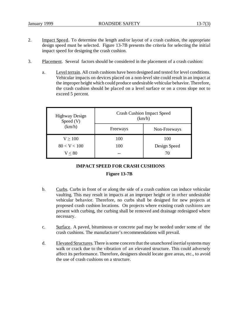
January 1999 ROADSIDE SAFETY 13-7(3)
2. Impact Speed. To determine the length and/or layout of a crash cushion, the appropriatedesign speed must be selected. Figure 13-7B presents the criteria for selecting the initialimpact speed for designing the crash cushion.
3. Placement. Several factors should be considered in the placement of a crash cushion:
a. Level terrain. All crash cushions have been designed and tested for level conditions.Vehicular impacts on devices placed on a non-level site could result in an impact atthe improper height which could produce undesirable vehicular behavior. Therefore,the crash cushion should be placed on a level surface or on a cross slope not toexceed 5 percent.
Highway DesignSpeed (V)
(km/h)
Crash Cushion Impact Speed(km/h)
Freeways Non-Freeways
V > 10080 < V < 100
V < 80
100100--
100Design Speed
70
IMPACT SPEED FOR CRASH CUSHIONS
Figure 13-7B
b. Curbs. Curbs in front of or along the side of a crash cushion can induce vehicularvaulting. This may result in impacts at an improper height or in other undesirablevehicular behavior. Therefore, no curbs shall be designed for new projects atproposed crash cushion locations. On projects where existing crash cushions arepresent with curbing, the curbing shall be removed and drainage redesigned wherenecessary.
c. Surface. A paved, bituminous or concrete pad may be needed under some of thecrash cushions. The manufacturer’s recommendations will prevail.
d. Elevated Structures. There is some concern that the unanchored inertial systems maywalk or crack due to the vibration of an elevated structure. This could adverselyaffect its performance. Therefore, designers should locate gore areas, etc., to avoidthe use of crash cushions on a structure.

13-7(4) ROADSIDE SAFETY January 1999
MARCH 2000
e. Reserve Area. The designer should, as early as practical in the project design process,determine the need for and approximate dimensions of a crash cushion. This willavoid late changes which could significantly affect the project design. Figure 13-7Cprovides recommended criteria for the crash cushion reserve area.
13-7.02 End Treatment Selection
Guide rail end treatments present a potential roadside hazard if not properly selected, designed, andinstalled. Department policy is that all new end treatments installed on the State-owned highwaysystem must meet the NCHRP Report 350 criteria (TL-3 minimum). This Section discusses thosetreatments which are acceptable for use.
13-7.02.01 End Treatment Design
For the leading ends of metal beam rail Type R-B 350 guide rail, the following will apply:
1. End Anchorage Outside Clear Zone. The preferred end treatment is to flare the guide railto outside the clear zone and use the End Anchorage Type I. See the Connecticut StandardSheets for details of the Type I end anchorage.
2. Earth Cut Slope and Rock Cut Anchorages. Wherever practical, use these anchorages forthe R-B 350. They eliminate the possibility of an errant vehicle striking the terminal end orrunning behind the terminal. The Connecticut Standard Sheets illustrate the details for theseanchorages with the R-B 350.
3. Terminal Within Clear Zone (NHS). If a crash worthy end terminal is needed to anchor W-beam guide rail within the clear zone, designers should choose an impact attenuator from theapproved list in the latest Guide Rail Procedure in Appendix A. When the recommendedlength of need in not attainable due to intersecting roads or driveways and when the use ofan impact attenuator or 3-cable guide rail is inappropriate, a radius rail with a Type II endanchor may be placed down the driveway. In some cases, an easement for placement of theanchor may be required. Refer to Section 13-6.07 for details and sight line requirements.
4. Terminal Within Clear Zone (Non-NHS). As with NHS roadways, designers should striveto anchor w-beam guide rail by extending the anchor outside the clear zone and/or anchoringthe end in an earth cut slope or rock outcrop. An impact attenuator may be used as a lastoption only if all grading requirements and design features can be obtained. Refer toDepartment grading plans for impact attenuators. If the above options are not appropriate,designers may consider regrading the roadside so that a proper anchor can be installed.Refer to Figure 13-6D for guide rail treatment at intersecting roads and driveways.
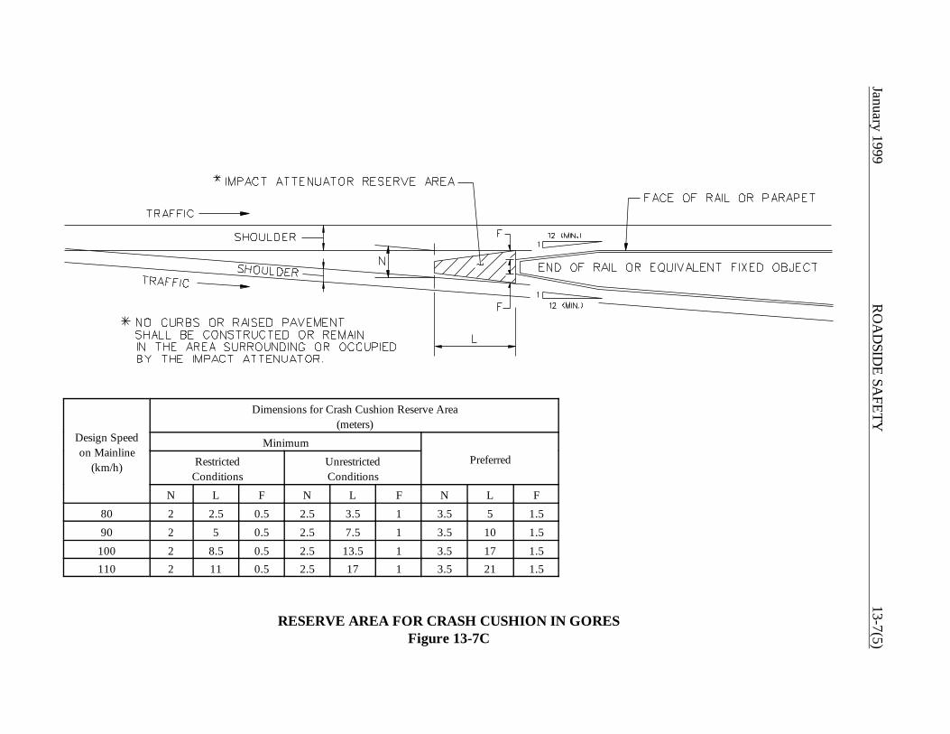
January 1999R
OA
DSID
E SAFETY
13-7(5)
Design Speedon Mainline
(km/h)
Dimensions for Crash Cushion Reserve Area(meters)
MinimumPreferredRestricted
ConditionsUnrestrictedConditions
N L F N L F N L F80 2 2.5 0.5 2.5 3.5 1 3.5 5 1.590 2 5 0.5 2.5 7.5 1 3.5 10 1.5
100 2 8.5 0.5 2.5 13.5 1 3.5 17 1.5110 2 11 0.5 2.5 17 1 3.5 21 1.5
RESERVE AREA FOR CRASH CUSHION IN GORESFigure 13-7C
13-7(6) ROADSIDE SAFETY January 1999
MARCH 2000
For the trailing ends of metal beam rail Type R-B 350 guide rail, the following will apply:
1. Undivided Facilities (NHS). The above criteria for the approach ends of Type R-B 350 alsoapplies to its trailing end on a two-way facility and on an undivided multi-lane facility.
2. One-Way Roadways (NHS and Non-NHS). These include interchange ramps and oneroadway of a divided facility. In these cases, the trailing end of Type R-B 350 may be theEnd Anchorage Type I placed within the clear zone. The rationale is that the end anchoragecannot be impacted head on.
13-7.02.02 Three Cable Guide Rail
It is not necessary to place the end anchorage outside of the clear zone. The following applies to itsend treatments:
1. End Anchorage Type I. This is the preferred end treatment.
2. End Anchorage Type II. This terminal is used where narrow openings must remain fordriveways, crossing roads, etc., and the use of the End Anchorage Type I is impractical.
See the Connecticut Standard Sheets for the use of each end treatment with three cable guide rail.
13-7.02.03 Merritt Parkway
See the Connecticut Standard Sheets and the latest Guide Rail Procedure in Appendix A foracceptable end treatments.
13-7.02.04 Metal Beam Rail Median Barrier (Type MD-B 350)
The Department uses these types of terminal treatments for the Type MD-B 350:
1. End Anchorage Type I. This treatment is used when the median metal beam rail can be flaredto a point outside the clear zone or to another safe location. The details for this terminal typeare illustrated in the Connecticut Standard Sheets.
2. Terminal End Treatments. There are several types of special end treatments available formedian metal beam rail. These end treatments are used where the terminal end for themedian rail cannot be flared to a point outside of the clear zone (e.g., in narrow medians).
The selection of the appropriate end treatment will be based on a case-by-case assessmentconsidering initial cost, maintenance, grading requirements, etc. Refer to the Guide RailProcedure in Appendix A for the Department approved list.
January 1999 ROADSIDE SAFETY 13-7(7)
MARCH 2000
When the medial rail extends down an on/off ramp to a T intersection, an MD-B EndAnchorage Type I may be used. The anchor shall be placed so that sight line is notcompromised and that clear zone requirements for the intersecting road is met.
13-7.02.05 Concrete Median Barrier
A variety of situations exist on Connecticut roadways where the leading ends of concretebarriers require shielding. Refer to the Guide Rail Procedure in Appendix A for theDepartment approved list.

January 1999 ROADSIDE SAFETY 13-8(1)
13-8.0 REFERENCES
1. Roadside Design Guide, AASHTO.
2. Guide for Selecting, Locating, and Designing Traffic Barriers, AASHTO, 1977.
3. A Supplement to A Guide for Selecting, Locating, and Designing Traffic Barriers,Texas Transportation Institute, March, 1980.
4. Safety Design and Operational Practices for Streets and Highways, FHWA, March,1980.
5. FHWA-IP-83-4 A Procedure for Determining Frequencies to Inspect and RepairHighway Safety Hardware, December, 1983.
6. Research Report 67-1 New Highway Barriers, The Practical Application ofTheoretical Design, New York Department of Public Works, May, 1967.
7. NYSDOT-ERD-76-RR38 Testing of Highway Barriers and Other SafetyAppurtenances, New York State Department of Transportation, December, 1976.
8. Transportation Research Record 970, “Development of Proposed Height Standardsand Tolerances for Light-Post Traffic Barriers,” James E. Bryden, 1984.
9. “A Roadside Design Procedure,” James Hatton, Federal Highway Administration,January, 1974.
10. FHWA/NY/RR-80/83 Crash Tests of Sharply Curved Light-Post Guide rail, NewYork State Department of Transportation, July, 1980.
11. NCHRP Report 150 Effect of Curb Geometry and Location on Vehicle Behavior,Transportation Research Board, 1974.
12. NCHRP Report 158 Selection of Safe Roadside Cross Sections, TransportationResearch Board, 1975.
13. NCHRP Synthesis 66 Glare Screen Guidelines, Transportation Research Board,December 1979.
14. NCHRP Report 350 Recommended Procedures for the Safety Performance ofHighway Features, Transportation Research Board, 1993.
15. Crash Cushions -- Selection and Design Criteria, FHWA, 1975.
16. “Crash Cushions, Safety Systems,” Technical Notebook, Energy Absorption Systems,Inc.
January 1999 ROADSIDE SAFETY 13-A(1)
Appendix
This Appendix to Chapter Thirteen presents the following:
1. Guide Rail Procedure
2. FHWA Technical Advisory T5040.32 “Curved W-Beam Guardrail Installations atMinor Roadway Intersections.”
April 2000
Guide Rail Procedure
1 of 8
When the American Association of State Highway and Transportation Officials and FederalHighway Administration’s (AASHTO-FHWA) agreement regarding the National CooperativeHighway Research Program (NCHRP) Report 350 was published in 1997, the Departmentdeveloped a procedure for its implementation dated, December 1, 1997. The followingprocedure will supersede that guide rail procedure.
It has always been Department practice to attempt to provide the traveling public with aforgiving roadside. Although a forgiving roadside is not always possible, every effort should bemade to eliminate the need for railing. When all means to remove the need for railing have beenexhausted, designers should refer to the following procedure and Chapter 13 of theDepartment's Highway Design Manual (HDM). When special instances arise, that are notaddressed in this procedure, the appropriate Division Manager must approve alternate designs.
Section 13-A.01: National Highway System (NHS) and StateRoadways with Design Speeds > 80kph and/or Traffic Volumes > 6000vpd and all Freeway Ramps
13-A.01.a Railing: All new roadside safety appurtenances installed on NHS and Stateroads, as noted above must meet the testing criteria found in NCHRP Report 350 Test Level 3(TL-3) or better.
1. When any of the longitudinal barriers requiring removal, as listed below, are within thelimits of a project, and their need cannot be eliminated, the railing shall be replaced with abarrier chosen from the approved longitudinal barrier list.
Longitudinal Barriers Requiring Removal:a) Two-cable on wood posts.b) Three cable with steel bracket on steel or wood posts.c) R-I and MD-I w-beam guide rails on weak steel posts.d) R-B and MD-B w-beam guide rails with the steel blockouts.
Approved Longitudinal Barriers:a) Three Cable Guide Railing (I-Beam Posts), TL-3.b) R-B 350 and MD-B 350 w-beam guide rail with polyethylene blockout, TL-3.c) 1145 mm F-shaped Precast Concrete Barrier Curb (PCBC), TL-5.
d) 152 mm x 152 mm roadside box beam, TL-3 *e) 152 mm x 200 mm median box beam, TL-3. *f) Thrie-beam 350 guide rail with modified steel blockout, TL-4+. *g) Innovative Barriers. See Section 13-A.01.e.
* Note: These barriers may only be used with the written permission of the Transportation Engineering Administrator.
April 2000
Guide Rail Procedure
2 of 8
2. New installations of R-I, MD-I, R-B, and MD-B guide rail are prohibited.
3. New R-B 350 guide rail including systems, anchors, and transitions installed on limitedaccess highways and ramps shall use 10 gauge w-beam rail elements. Standard sheets havebeen revised to include this change.
4. Existing guide rail types R-I, MD-I, R-B, and MD-B shall be either eliminated,replaced, or converted to R-B 350 or MD-B 350. See Department Specifications.
5. Avoid gaps less than 60 m between guide rail end anchors.
13-A.01.b Anchors:
1. Leading-end, turned-down end anchors, except three cable guide railing(I-Beam Posts), are no longer allowed within the clear zone. Refer to HDM Section 13-2 forclear zone applications. Existing leading end anchors within the limits of a project in the clear-zone shall be either flared away from the roadway to meet clear-zone requirements, anchoredinto an earth-cut slope, attached to a rock face or, as a last option, installed with an impactattenuator. When proposing an impact attenuator, refer to the attached chart for designparameters and the Department's standard sheets for grading requirements. There shall be nocurbing in front of, or fixed objects in the vicinity of, any impact attenuator.
2. Remove all existing leading-end blunt ends and terminate the rail using an appropriateend treatment chosen from Section 13-A.01.b1 above.
3. Pavement for railing shall be used only within public water supply watershed areas andat the approaches to bridges over waterways. In all other areas and when the water course isgreater than 15.24 m from the road and paralleling it, use processed aggregate under railing.Some impact attenuators require a deck structure and others may be installed with processedaggregate or pavement for railing.
4. Trailing-end, turned-down end anchors for w-beam guide rail may continue to beplaced within the clear-zone on divided or one-way roadways. On bi-directionalroadways, the trailing-end, turned-down end anchor shall be placed outside theclear-zone. The clear-zone, in this case, is measured from the centerline of the road to the lastpost before the turndown. The concrete anchor for the turndown shall then be measured andplaced as shown on the Department's standard sheets.
5. When the recommended length of need is not attainable due to intersecting roads ordriveways and when the use of an impact attenuator or three cable guide rail is inappropriate, aradius rail with a Type II end anchor may be placed down the driveway. In some cases, aneasement for placement of the anchor may be required. Refer to the HDM Section 13-6.07 fordetails and sight line requirements.
April 2000
Guide Rail Procedure
3 of 8
13-A.01.c Guide Rail to Bridge Rail Transitions:
1. At this time, the R-B 350 transition to a vertical-shaped bridge parapet has successfullymet NCHRP Report 350 guidelines. FHWA has scheduled testing for theR-B 350 transition to a safety-shaped parapet and expects results by September of 2000.(Both of these transitions were originally approved by FHWA per NCHRP Report 230guidelines.)
2. All existing bridge rail transitions not meeting NCHRP Report 230 requirements withinthe limits of a project shall be converted to one of the R-B 350 guide rail transitions. Adeficient-approach guide rail is one where the rubrail is not attached to the parapet, where thesystem improperly transitions strength, or where the system is completely unattached.
3. The R-B 350 trailing-end bridge attachment shall only be designed forsingle-direction roadways. All four corners of a bridge on a bi-directional roadway shall betreated as an approach end regardless of clear-zone requirements.
13-A.01.d Curbs and Curb/Barrier Combinations:
1. The standard curb used on high-speed, high-volume NHS or State roadways shall bethe 100 mm bituminous concrete park curbing shown in the Department standard sheets.
2. When w-beam guide rail is installed without curb, it may be placed 305 mm or morefrom the edge of pavement only on slopes 1:10 or flatter. If the rail is installed within 600 mm ofthe edge of shoulder, the rail height is measured from the shoulder slope extended to the rail. Ifthe rail is installed beyond 600 mm from the edge of shoulder, the rail height is measured fromthe ground directly below the rail. Deflection requirements must be adhered to at all times.
3. When w-beam guide rail is installed with curb, install it flush with the face of curb andmeasure the rail height from the top of pavement. If curb and sidewalk are present and the rail isplaced behind the sidewalk, measure the rail height from the top of sidewalk. Deflectionrequirements must be adhered to at all times.
4. The use of granite stone transition curbing (gstc) has been discontinued. Existing gstcmay remain in place if a 100 mm reveal at the parapet can be obtained to accommodate the R-B 350 Safety Shape Attachment. If the existing curb does not have a 100 mm reveal, replace itwith the Department standard curb. When installing the R-B 350 Vertical Shape Attachment,measure the rail height from the top of curb.
April 2000
Guide Rail Procedure
4 of 8
13-A.01.e Innovative Barriers:
1. Section 328 of the NHS Act entitled Roadside Barrier Technology requires 2.5% of allbarrier installed on the NHS beginning with calendar year 1996 to be innovative. The termbarrier, as used in Section 328, includes both temporary and permanent median and roadsidebarrier, but excludes guide rail. The following is a list of NCHRP Report 350 approvedinnovative barriers. Designers should review and investigate the possibility of using them in theirprojects.
Permanent:1070 mm high (or higher) Jersey-Shaped PCBC.1070 mm high (or higher) F-Shaped PCBC. (Dept. standard is 1145mm)1070 mm high (or higher) Vertical-Shaped PCBC.1070 mm high (or higher) Single-Sloped PCBC.
13-A.01.f Concrete Barriers:
1. Due to the superior performance during crash tests, FHWA has deemed theF-Shape PCBC as the preferred barrier shape. Therefore, 1145 mm F-Shape PCBC shall beused for new construction to provide positive median separation on limited access highways orwhen needed on the roadside. Replacement of existing Jersey Shape PCBC within the limits ofa project is not required.
2. Temporary median Jersey-shaped PCBC may continue to be used for maintenance andprotection of traffic during construction provided that positive moment connection between thebarriers as shown in the Department Special Provision 822 or Miscellaneous Connecticut Detailis incorporated.
13-A.02 Merritt Parkway
13-A.02.a Railing:
1. The Merritt Parkway Guide rail (MPGR) has successfully met NCHRP Report 350TL-3 guidelines and is approved exclusively for use on the Merritt Parkway. Any existinglongitudinal barrier requiring replacement within the limits of a project shall be replaced with theMPGR. Refer to Section 13-A.01.a for the list of longitudinal barrier requiring replacement.
13-A.02.b Anchors:
1. A crash-worthy end treatment is not available for MPGR. Use one of the followingapplications to anchor the leading-end.
a) Anchor the rail to a rock face.
April 2000
Guide Rail Procedure
5 of 8
b) Bury the anchor in an earth cut slope.c) Place the anchor outside the clear zone and bury the end.d) Bury the anchor in a built-up berm.(Use only as a last option.)
13-A.02.c Guide rail to Bridge Rail Transitions:
1. The MPGR transition to a bridge rail has been successfully crash tested to meetNCHRP Report 350 TL-3 guidelines. It was tested with gstc and is currently the only placewhere new gstc can be installed. Refer to Department standard sheets and the HDM Sections13-4 and 13-5 for more information.
13-A.03 State Roadways with Design Speeds < 80kph and TrafficVolumes < 6000 vpd
13-A.03.a Railing:
1. Existing metal beam rail (type R-I and R-B) does not need to be replaced provided itmeets length of need and deflection requirements. The rail shall be extended if the length of needis inadequate. All other new installations of guide rail should meet the testing criteria in NCHRPReport 350. 2. Replace rail such as two-cable on wood posts and three cable with steelbrackets on wood or steel posts according to Department standards, even if the run of railextends beyond the project limits.
13-A.03.b Anchors:
1. Review existing anchors for location and type. Extend the anchor to meetclear-zone requirements or anchor it into an earth cut slope or rock face. Use an impactattenuator only if all grading requirements and design features can be obtained. Refer tostandard grading plans for proper installation. If the railing can be extended up to an additional60 m to provide proper anchorage, this should be done instead of installing an impactattenuator. Types R-I and MD-I guide rail needing an impact attenuator will require 7.62 m ofstrong post transition before installing the impact attenuator.
2. Do not terminate guide rail at a second rail type unless a transition meeting Departmentstandards can be applied. Refer to HDM Section 13-6.09.02 and Figure 13-6G.Never transition or terminate guide rail at a critical juncture such as at the radii of intersections.
3. If the above options are not appropriate, designers may consider re-grading theroadside so that a proper anchor can be installed. Refer to figure 13-6D in the HDM for guiderail treatment at intersecting roads and driveways.

April 2000
Guide Rail Procedure
6 of 8
13-A.03.c Guide Rail to Bridge Rail Transition:
1. Unconnected top rail and/or rubrail for bridge-approach guide rail transitions shall beconnected with an approved transition design meeting the requirements of NCHRP Report 350.See Department standard sheets. Existing bridge-approach guide rail transitions for types R-I orR-B are acceptable provided any rubrail is also attached.
13-A.04 Scenic Roadways
1. For installations on scenic roads, the designer will have the option of using ASTMA-588 steel, “weathering steel” rail elements and posts for metal beam rail, and weathering steelposts for three cable guide rail (I-beam posts). Where there is a large body of water, such asmajor rivers and lakes adjacent to a scenic roadway or within the roadway fill slope, thedesigner has the option of using galvanized or weathering steel box beam rail elements andposts. If the body of water is a potable reservoir, Section 13-3.08 of the HDM governs.
13-A.05 Local Roadways
1. Municipalities are encouraged to use current Department guide rail standards, andprocedures for their roadside safety appurtenances. Refer to Chapters Two, Four, Five andThirteen of the HDM.
13-A.06 General
1. When a designer considers using three cable guide rail (I-beam posts), accident historyshould be investigated. If the accident history shows a significant number of accidents haveoccurred; designers should consider using R-B 350 guide rail instead. In this case, R-B 350guide rail may be more appropriate because it may remain in services after a hit where as thethree cable may not.
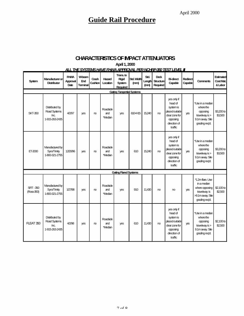
April 2000
Guide Rail Procedure
7 of 8
CHARACTERISTICS OF IMPACT ATTENUATORSApril 1, 2000
ALL THE SYSTEMS HAVE FHWA APPROVAL PER NCHRP-350 TEST LEVEL III
SystemManufacturer or
Distributor
FHWA Approval
Date
W-beam End
Terminal
Crash Cushion
Hazard Location
Trans. to Rigid
System Required
Std. Width (mm)
Std. Length (mm)
Deck Structure Required
Bi-direct Capable
Redirect Capable Comments
Estimated Cost Mat. & Labor
Gating Tangential Systems
SKT-350
Distributed by Road Systems
Inc. 1-915-263-2435
4/2/97 yes noRoadside
and *Median
yes 610+H15 15,240 no
yes only if head of
system is placed outside clear zone for
opposing direction of
traffic
yes
*Use in a median where the opposing
travelway is > 9.1m away. Site grading req'd.
$3,200 to $3,500
ET-2000Manufactured by
Syro/Trinity 1-800-321-2755
12/20/96 yes noRoadside
and *Median
yes 610 15,240 no
yes only if head of
system is placed outside clear zone for
opposing direction of
traffic
yes
*Use in a median where the opposing
travelway is > 9.1m away. Site grading req'd.
$3,200 to $3,500
Gating Flared Systems
SRT - 350 (Ross-350)
Manufactured by Syro/Trinity
1-800-321-27551/27/98 yes no
Roadside and
*Medianyes 910 11,430 no no yes
*1.2m flare. Use in a median
where opposing travelway is
>9.1m away. Site grading req'd.
$2,100 to $2,500
FLEAT 350
Distributed by Road Systems
Inc. 1-915-263-2435
4/2/98 yes noRoadside
and *Median
yes 610 11,430 no
yes only if head of
system is placed outside clear zone for
opposing direction of
traffic
yes
*Use in a median where the opposing
travelway is > 9.1m away. Site grading req'd.
$2,100 to $2,500

April 2000
Guide Rail Procedure
8 of 8
CHARACTERISTICS OF IMPACT ATTENUATORS April 1, 2000
ALL THE SYSTEMS HAVE FHWA APPROVAL PER NCHRP-350 TEST LEVEL III
SystemManufacturer or
Distributor
FHWA Approval
Date
W-beam End
Terminal
Crash Cushion
Hazard Location
Trans. to Rigid
System Required
Std. Width (mm)
Std. Length (mm)
Deck Structure Required
Bidirect Capable
Redirect Capable
CommentsEstimated Cost Mat. & Labor
Gating Bi-directional Systems
BRAKEMASTERDistributed by
TRANSPO 1-800-321-7870
6/19/97 yes yesRoadside *Median and Gore
yes 610 9125 yes yes yes
*Median width 6.1m or more. Site grading
req'd.
$5,000
C-A-TManufactured by
Syro/Trinity 1-800-321-2755
5/1/96 yes yesRoadside,
Median and Gore
yes 705 9125 no yes yesSite grading
req'd.$5,000
ADIEM 350Manufactured by
Syro/Trinity 1-800-321-2755
3/3/97 yes yesRoadside
and Medianno 711 9144 yes yes yes
Use to shield fixed objects 610
mm wide. $13,500
Gating Sand Barrel Systems
FITCH UNIVERSAL MODULE BARRELS
Distributed by TRANSPO
1-800-321-7870 6/28/95 no yes
Roadside, Median &
Goreno
1980 to unlimited
5496 to 11887 no yes no
Primarily used as a temporary
barrier
$375 per barrel
ENERGITE III (BARRELS)
Distributed by TRANSPO
1-800-321-7870 6/28/95 no yes
Roadside, Median &
Goreno
1980 to unlimited
5496 to 11887
no yes noPrimarily used as
a temporary barrier
$375 per barrel
Non - Gating Systems
REACT 350 Family
Distributed by TRANSPO
1-800-321-7870
Various Dates
yes yesRoadside, Median &
Gore
no (Transition to
W-beam Available)
914 to 3048
4704 to 9296
yes yes yes
Primarily used in locations where a
high # of accidents have
occurred on high speed high
volume roadways
$15,000 to $28,000
QUADGUARD Family
Distributed by TRANSPO
1-800-321-7870
Various Dates
no yesRoadside, Median &
Goreno 610 to
22861740 to 11,810
yes yes yesPrimarily used to
shield fixed objects
$7500 to $30,000
NCIAS CTDOT 3/26/99 no yesRoadside, Median &
Gore
Back up Support Required
914 9144 no yes yes Non-Proprietary $12,000
TRACCManufactured by
Syro/Trinity 1-800-321-2755
11/13/98 yes yesRoadside, Median &
Goreno 800 6040 yes yes yes
Unit is shipped completely assembled
$10,500
CURVED W-BEAM GUARDRAILINSTALLATIONS AT MINOR ROADWAYINTERSECTIONS
T 5040.32 April 13, 1992
Par. 1. Purpose2. Background3. Summary4. Recommendations5. Related Technical Information
1. PURPOSE. To transmit information on two different operationaldesigns of curved guardrail for radii between 8½ and 35feet, as well as a specialized application of an 8½ footradius curved guardrail. These new designs have beensuccessfully crash tested and are acceptable for newconstruction, as well as for improving safety at existing sites. These designs are most appropriate for use on low volumehighways.
2. BACKGROUND
a. Often roads or driveways intersect a highway close to theend of a bridge or other immovable, restrictive features ofthe highway. To shield both the end of the bridge and thesteep embankment, a strong post W-beam guardrail curvedaround the radius is typically used. Often, theseinstallations have not been effective when the curvedsection of the barrier has been hit at higher speeds. Avehicle which impacts the barrier under such conditions willgenerally vault over or penetrate the guardrail; or, in theevent that the vehicle is contained by the guardrail, theresulting decelerating forces often exceed the recommendedlimits for occupant safety. In many of these situations, itis not practical to change the site conditions by relocatingthe intersecting roadway further away from the bridge end inorder to allow room for a standard approach guardrail. Itwas, therefore, necessary to develop a curved guardrailinstallation which would substantially improve the safety atthese sites.
FHWA TECHNICAL ADVISORY T 5040.32April 13, 1992
2
b. A cooperative research program between the Washington StateDepartment of Transportation and the Federal HighwayAdministration was undertaken to design improved curvedguardrail approaches and transitions. Subsequently, Yuma Countyin Arizona tested and developed a stiffer 8½-foot radius curvedguardrail for sites where canals or other features such asdrainage are close to the guardrail. Both systems are intendedprimarily for use on lower-speed through roadways intersected bylow-speed, low-volume roads, driveways, or maintenance rights-of-way.
3. SUMMARY
a. This information can be used to enhance highway safety incertain locations where it is desirable to use curved strongpost guardrail sections. This information is appropriate foruse in new construction and for improving or upgrading existingcurved guardrail installations.
b. The curved sections have been successfully crash tested withinthe performance limits detailed in this Technical Advisory. Crash tests also indicated that these sections have limitationsand should not be used in situations which vary excessively fromthe conditions (such as grading, layout, or vehicle speed) underwhich these successful crash test results were obtained.
c. Adherence to detail is important. Guardrail section layout andconstruction details such as rates of curvature, use ofbreakaway Controlled Releasing Terminal (CRT) posts, adequatedeflection zone behind curved guardrail and appropriate endanchorages are elements which can critically affect performance.
d. The recommended designs and details listed below are shown inthe attached drawings:
(1) Figure 1: Curved W-Beam Guardrail Installation for an 8½-foot radius.
(2) Figure 2: Curved W-Beam Guardrail Installation for a 35-foot radius.
(3) Figure 3a: Special Anchor Details.
FHWA TECHNICAL ADVISORY T 5040.32April 13, 1992
3
(4) Figure 3b: Special Anchor Details.
(5) Figure 4: Yuma County, AZ, Curved W-Beam GuardrailInstallation for an 8½-foot radius.
4. RECOMMENDATIONS
a. The curved guardrail designs detailed in this Technical Advisoryshould be considered for use in new construction projects asappropriate. Existing curved guardrail installations may alsobe replaced or upgraded as the opportunity becomes available.
b. These curved guardrail designs are for radii of 8½ feet and 35feet. Crash test results and technical experience indicate thatthis system will also perform satisfactorily with otherintermediate radii as noted in the table on Figure 1. Situations which require a curved guardrail installation whichfalls beyond this range of radii should be designed individuallyand not subjected to a "make it fit" misapplication of thesedetails.
5. RELATED TECHNICAL INFORMATION
a. The following details are essential to proper system performancein the field:
(1) Breakaway CRT posts are used within the curved "nose" of theguardrail installation. Wood blockouts are not used on theCRT posts. The W-beam rail in the curved area is attacheddirectly to the CRT post with a button-head bolt which hasno washer. This is done to have the posts break away in thecurved nose area and thus separate from the rail. Thisminimizes rotation of the rail during impact and minimizesthe likelihood that a vehicle will vault over the guardrailupon impact.
(2) For the 8½-foot radius layout (Figure 1), the guardrail isnot bolted to the one CRT post at the center of the curvednose area. This allows the center post to easily separatefrom the guardrail
upon impact, and facilitates guardrail deflectionwithout having this bolt ripping or snagging the W-beam rail section.
FHWA TECHNICAL ADVISORY T 5040.32April 13, 1992
4
(3) A flat approach to the curved guardrail installation isnecessary in order to ensure proper performance of thesystem. The slope in front of the installation should notexceed 15:1. If the installation is on a superelevatedsection, analysis should be performed in order to evaluatethe potential for vaulting of an errant vehicle.
(4) The embankment slope should break at least 2 feet behind thepost (so that the post will have adequate bearing strengthwhen hit). It is desirable that the embankment slopesbehind the guardrail not be steeper than 2:1. Successfulcrash tests were done on installations with 2:1 slopesbehind the guardrail.
(5) Considerable deflection of the W-beam guardrail can beexpected with higher speed impacts on the curved guardrailportion of the installation. Therefore, the area behind thecurved portion of the guardrail, shown as the cross-hatchedareas on Figures 1, 2 and 4, must be kept free of fixedobjects.
b. These curved guardrail installations are not appropriate for use inall situations. To avoid misapplication, the designer should beaware of the following limitations:
(1) When used in close proximity to a bridge with a rigid bridgerail, these design layouts require an adequate space betweenthe curved guardrail installation and the bridge end(approximately 25 feet) to place a crashworthy W-beamtransition from the W-beam guardrail to a rigid bridge rail.
(2) Since the special end anchor shown in Figures 3A and 3B hasnot been crash tested as a guardrail terminal, its useshould be limited to low-speed, low-volume facilities with astop condition such as intersecting driveways or service-type roadways. For most intersecting public highways, thecurved guardrail installation should be either terminatedalong the intersecting roadway with an acceptable terminalsystem, or connected to an existing guardrail system.
(3) The special end anchor system was developed for use when itis necessary to end the guardrail system immediately afterthe curved section. This end anchor uses many components

FHWA TECHNICAL ADVISORY T 5040.32April 13, 1992
5
from the breakaway cable terminal design. It also includesanother cable to connect the steel foundation of the next-to-last post to the end post anchoring cable system. Onenovel feature incorporated is a pivoting pipe section whichis placed over the end post and improves rail performance byallowing it to swivel as it is deflected by a car. Thisspecial end anchor is not a crashworthy terminal for highspeed highways. Therefore, as stated previously, its useshould be limited to driveways or service roadways.
(4) In the high speed crash tests, some heavy debris wasobserved flying about in the area behind the impact. Judgment must be used when installing these sections wherepeople are likely to be present in the area behind thecurved section.
c. Curved guardrail installations of the Washington State design havingradii of 8½ feet and 35 feet were successfully crash tested, but itshould be noted that the 35-foot radius installation did not performadequately when impacted at 60 MPH by a large vehicle (4740 lbs.). Satisfactory results were obtained for the 35-foot radiusinstallation when a test was performed at a reduced speed of 50 MPHwith the large vehicle. Two intermediate radii (17 feet and 25½feet) are provided in Figure 1. Installations having a differentradius between 8½ feet and 35 feet must be specially detailedso as to use only full lengths of W-beam rail, and to shop bend onlyfull sections of rail. Any such intermediate radius designs mustincorporate all other critical details and post types and locationsas shown on the attached Figures 1 and 2 in order to be consideredacceptable.
(1) It is important to note that the Yuma County design shown inFigure 4 was successfully crash tested at 50 mph. Radii largerthan 8½ feet should not be used without further testing.
(2) All of the attached designs are based on an intersection angleof 90 degrees. If field conditions vary excessively from 90degrees, it will be necessary to specially detail a curvedguardrail section so that the curved rails will fit theintersection geometry, and that only full sections of W-beamrail will be shop bent for installation.
d. The attached drawings, in a format suitable for use on the
FHWA TECHNICAL ADVISORY T 5040.32April 13, 1992
6
Intergraph CAD system, are available from the Federal HighwayAdministration, Office of Engineering, Geometric and Roadside DesignBranch, HNG-14, 400 Seventh Street, S.W., Washington, D.C. 20590.
/s/ Thomas O. Willett /s/ R. Clarke Bennett Thomas O. Willett R. Clarke BennettDirector, Office of Engineering Director, Office of
Highway Safety
Attachments (Not on disk-see printed copy of Technical Advisory)
January 1999 M & P OF TRAFFIC THROUGH CONSTRUCTION ZONES 14-i
Chapter Fourteen
MAINTENANCE AND PROTECTION OFTRAFFIC THROUGH CONSTRUCTION ZONES
Table of Contents
Page
14-1.0 GENERAL . . . . . . . . . . . . . . . . . . . . . . . . . . . . . . . . . . . . . . . . . . . . . . . . . . . 14-1(1)
14-1.01 Responsibilities . . . . . . . . . . . . . . . . . . . . . . . . . . . . . . . . . . . . . . . . 14-1(1) 14-1.02 Maintenance and Protection of Traffic Plans (MPT) . . . . . . . . . . 14-1(2)
14-2.0 TRAFFIC CONTROL MANAGEMENT . . . . . . . . . . . . . . . . . . . . . . . . . . . . 14-2(1)
14-2.01 Work Zone Type . . . . . . . . . . . . . . . . . . . . . . . . . . . . . . . . . . . . . . 14-2(1) 14-2.02 Work Zone Traffic Control Strategy . . . . . . . . . . . . . . . . . . . . . . . 14-2(2)
14-3.0 GEOMETRIC DESIGN . . . . . . . . . . . . . . . . . . . . . . . . . . . . . . . . . . . . . . . . . 14-3(1)
14-3.01 Design Speed . . . . . . . . . . . . . . . . . . . . . . . . . . . . . . . . . . . . . . . . . 14-3(1) 14-3.02 Sight Distance . . . . . . . . . . . . . . . . . . . . . . . . . . . . . . . . . . . . . . . . . 14-3(1) 14-3.03 Lane/Shoulders Widths . . . . . . . . . . . . . . . . . . . . . . . . . . . . . . . . . 14-3(1) 14-3.04 Transition Taper Rates . . . . . . . . . . . . . . . . . . . . . . . . . . . . . . . . . . 14-3(2) 14-3.05 Alignment . . . . . . . . . . . . . . . . . . . . . . . . . . . . . . . . . . . . . . . . . . . . 14-3(4) 14-3.06 Exceptions . . . . . . . . . . . . . . . . . . . . . . . . . . . . . . . . . . . . . . . . . . . 14-3(4)
14-4.0 ROADSIDE SAFETY . . . . . . . . . . . . . . . . . . . . . . . . . . . . . . . . . . . . . . . . . . . 14-4(1)
14-4.01 Warrants for Positive Protection . . . . . . . . . . . . . . . . . . . . . . . . . . 14-4(1) 14-4.02 Clear Zones . . . . . . . . . . . . . . . . . . . . . . . . . . . . . . . . . . . . . . . . . . 14-4(2) 14-4.03 Roadside Barriers . . . . . . . . . . . . . . . . . . . . . . . . . . . . . . . . . . . . . . 14-4(2) 14-4.04 End Treatments . . . . . . . . . . . . . . . . . . . . . . . . . . . . . . . . . . . . . . . 14-4(3) 14-4.05 Design/Layout . . . . . . . . . . . . . . . . . . . . . . . . . . . . . . . . . . . . . . . . 14-4(3)
14-5.0 REFERENCES . . . . . . . . . . . . . . . . . . . . . . . . . . . . . . . . . . . . . . . . . . . . . . . . . 14-5(1)

14-ii M & P OF TRAFFIC THROUGH CONSTRUCTION ZONES January 1999

January 1999 M & P OF TRAFFIC THROUGH CONSTRUCTION ZONES 14-1(1)
Chapter Fourteen
MAINTENANCE AND PROTECTION OFTRAFFIC THROUGH CONSTRUCTION ZONES
14-1.0 GENERAL
Because much of the Department's highway program will include work on existing highways, highwayconstruction will often disrupt existing traffic operations. Therefore, the designer must devote specialattention to traffic control in construction zones to minimize possible operational and safety problemsthrough the work zone.
14-1.01 Responsibilities
The following summarizes the division of responsibilities for the Maintenance and Protection of Traffic(MPT):
1. Designer. The prime designer is responsible for initiating action on the MPT, and he/she will requestinput from the Division of Traffic Engineering. If a temporary road will be constructed for trafficduring construction (i.e., a detour), the designer is responsible for its geometric and roadside safetydesign. The designer will work with Traffic to determine the traffic control strategy for the MPTon existing roads; see Section 14-2.0. Also, the designer is responsible for ensuring that thehighway can be constructed using the developed MPT plans.
2. Division of Traffic Engineering. Traffic will prepare or review the traffic control plans, including alltraffic control devices, on all projects on all temporary, proposed and existing roads. Traffic alsomaintains special standard sheets for traffic control devices, which are included with all projects.For a temporary road which will be used by traffic during construction, Traffic will provide thelayout or review the layout of all traffic control devices on that road. Traffic and the designer willwork together to determine the traffic control strategy for the MPT.
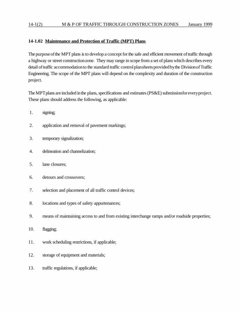
14-1(2) M & P OF TRAFFIC THROUGH CONSTRUCTION ZONES January 1999
14-1.02 Maintenance and Protection of Traffic (MPT) Plans
The purpose of the MPT plans is to develop a concept for the safe and efficient movement of traffic througha highway or street construction zone. They may range in scope from a set of plans which describes everydetail of traffic accommodation to the standard traffic control plan sheets provided by the Division of TrafficEngineering. The scope of the MPT plans will depend on the complexity and duration of the constructionproject.
The MPT plans are included in the plans, specifications and estimates (PS&E) submission for every project.These plans should address the following, as applicable:
1. signing; 2. application and removal of pavement markings;
3. temporary signalization;
4. delineation and channelization;
5. lane closures;
6. detours and crossovers;
7. selection and placement of all traffic control devices;
8. locations and types of safety appurtenances;
9. means of maintaining access to and from existing interchange ramps and/or roadside properties; 10. flagging;
11. work scheduling restrictions, if applicable;
12. storage of equipment and materials;
13. traffic regulations, if applicable;

January 1999 M & P OF TRAFFIC THROUGH CONSTRUCTION ZONES 14-1(3)
14. duration of use of any traffic control feature (throughout construction period, only during closureof left lane, etc.);
15. surveillance and inspection requirements;
16. contractor access to the work site;
17. coordination with any other construction projects;
18. truck-mounted attenuators;
19. capacity analyses;
20. liquidated damages; and/or
21. use of special materials.
For construction work which may involve a significant disruption to existing traffic operations, the designershould consider during the MPT plan development the likely impact on all affected local interests. Theseinclude, where applicable, the operations of the local:
1. public works or highway/street department,2. police,3. fire department,4. ambulance services,5. public transportation services,6. school boards, 7. pedestrians and bicyclists, and8. businesses.

14-1(4) M & P OF TRAFFIC THROUGH CONSTRUCTION ZONES January 1999
January 1999 M & P OF TRAFFIC THROUGH CONSTRUCTION ZONES 14-2(1)
14-2.0 TRAFFIC CONTROL MANAGEMENT
14-2.01 Work Zone Type
There are several basic work zone types that may be considered in a maintenance and protection of trafficplan. Note that work sites which are completely off the roadway and do not disrupt traffic are notaddressed because they will generally not have a major effect on traffic. The following presents adescription for each of the work zone applications:
1. Lane Constriction. This work zone type is configured by reducing the width of one or more lanesto retain the number of lanes normally available to traffic. This application is the least disruptive ofall work zone types, but it is generally appropriate only if the work area is mostly outside thenormal traffic lanes. It should be noted that narrow lane widths may reduce the facility's capacity,especially where there is significant truck traffic. The use of shoulders as part of the lane width willhelp reduce the amount of lane width reduction that may be required. Where this application isapplied for long-term work zones, the current lane markings must be obliterated to avoid motoristconfusion. Section 14-3.0 discusses the minimum lane widths that must be provided.
2. Lane Closure. This work zone type closes off one or more normal traffic lanes. Capacity and delayanalyses may be required to determine whether serious congestion will result from lane closures.In some cases, use of the shoulder or median area as a temporary lane will mitigate the problemsarising from the loss in capacity. Upgrading or replacement of existing pavement may benecessary.
3. Alternating One-Way Traffic Operation. This work zone type involves utilizing one lane for bothdirections of traffic. Flaggers or signals are normally used to coordinate the alternating directionsof traffic. Signing alone may be sufficient for short-term work zones on very low-volume, 2-laneroads. This work zone type is generally only applicable for low- and intermediate-volume roadsor short-term work zones.
4. Temporary Roadway. This work zone involves the total closure of the roadway (one or bothdirections) where work is being performed and the traffic is rerouted to a temporary roadway. Thisapplication may require the purchase of temporary right-of-way and usually requires extensivepreparation of the temporary roadway.
5. Intermittent Closure. This work zone type involves stopping all traffic in one or both directions fora relatively short period of time to allow the work to proceed. After a specific time, depending ontraffic volumes, the roadway is re-opened and all vehicles can travel through the area. This

14-2(2) M & P OF TRAFFIC THROUGH CONSTRUCTION ZONES January 1999
application is normally only appropriate on low-volume roadways or during time periods wherethere are very low volumes (e.g., Sunday mornings).
6. Use of Shoulder or Median. This work zone type involves using the shoulder or the median as atemporary traffic lane. To use this technique, it may be necessary to upgrade the shoulder toadequately support the anticipated traffic loads. This technique may be used in combination withother work zone types or as a separate technique.
7. Crossover. This work zone type involves routing a portion or all of one direction of the trafficstream across the median to the opposite traffic lanes. This application might also incorporate theuse of shoulders and/or lane constrictions to maintain the same number of lanes. Section 14-3.0discusses the geometric design criteria that should be used to develop crossovers.
8. Detour. This work zone type involves total closure of the roadway (one or both directions) wherework is being performed and rerouting the traffic to existing alternate facilities. This application maybe used where there is unused capacity on roads running parallel to the closed roadway.
The designer must also carefully consider the impact that the detoured traffic will have on otherState or local roads. A detour agreement with the Town is required when the State highway trafficis detoured onto a local road. The Division of Traffic Engineering is responsible for coordinatingbetween the State and Town(s).
14-2.02 Work Zone Traffic Control Strategy
Selection of the appropriate work zone type represents one of the most significant elements of a controlstrategy. Other elements of a control strategy that should be considered include length of the work zone,time of work, number of lanes, width of lanes, traffic speeds and right-of-way. Considering these and otherfactors, reasonable alternates can be narrowed to a selected few for further review. Typically, only a smallnumber of feasible work zone alternates will emerge for a particular project and, in many cases, only onemay be practical. Identification of these alternates at an early stage in the planning process can reducesignificantly the analysis effort necessary.
Figure 14-2A provides guidelines for identifying feasible work zone alternates based on roadway type, laneclosure requirements, shoulder width, traffic volume, and the availability of right-of-way and detour routes.However, it should be recognized that every work zone location will have a wide variation of conditionsand that an all-inclusive selection matrix is not practical.

January 1999 M & P OF TRAFFIC THROUGH CONSTRUCTION ZONES 14-2(3)
In using Figure 14-2A, local policy and regulations should be recognized. Many jurisdictions have adoptedsafety regulations and public convenience policies as safeguards against the unacceptable impacts of workzones. These regulations and policies may impose additional constraints regarding the types of controlstrategies that can be implemented. Knowing these constraints can help eliminate infeasible alternates fromconsideration. The public convenience policies or local regulations may specify peak hour restrictions,access requirements, noise level limitations, material storage and handling, excavation procedures, workzone lengths and number of traffic lanes that must remain open.
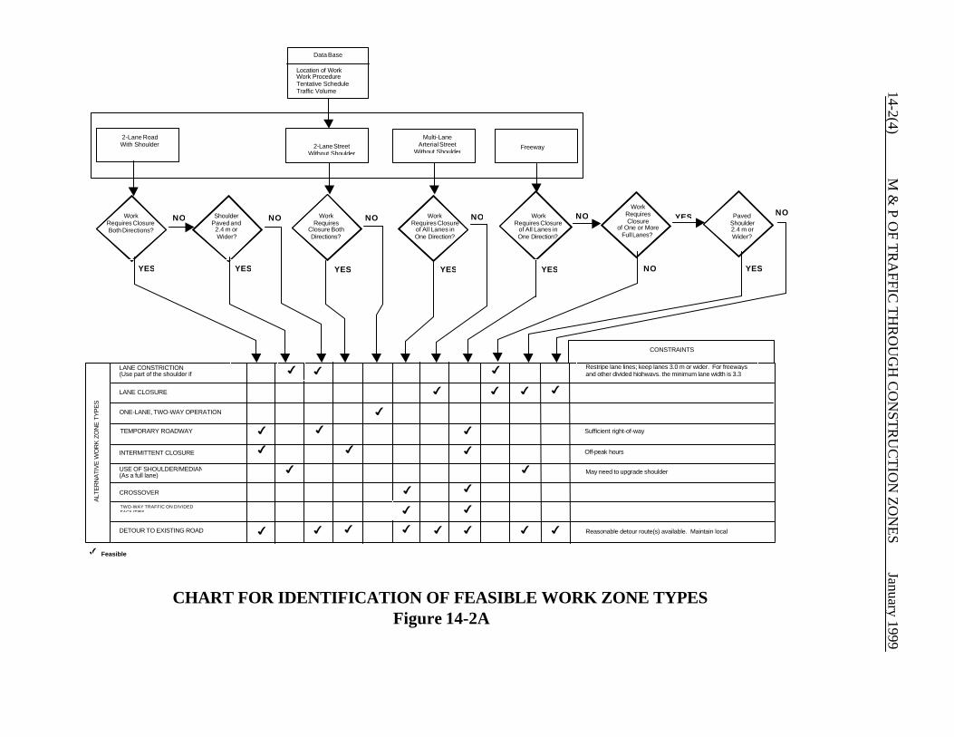
Location of WorkWork ProcedureTentative ScheduleTraffic Volume
4
4
4
4
4
Data Base
WorkRequires
Closure BothDirections?
2-Lane StreetWithout Shoulder
ShoulderPaved and
2.4 m orWider?
WorkRequires Closure
of All Lanes inOne Direction?
WorkRequires Closure
of All Lanes inOne Direction?
2-Lane RoadWith Shoulder
WorkRequires ClosureBoth Directions?
WorkRequiresClosure
of One or MoreFull Lanes?
Multi-LaneArterial Street
Without ShoulderFreeway
PavedShoulder2.4 m orWider?
LANE CONSTRICTION(Use part of the shoulder if
LANE CLOSURE
ONE-LANE, TWO-WAY OPERATION
DETOUR TO EXISTING ROAD
CROSSOVER
INTERMITTENT CLOSURE
TEMPORARY ROADWAY
USE OF SHOULDER/MEDIAN(As a full lane)
Restripe lane lines; keep lanes 3.0 m or wider. For freewaysand other divided highways, the minimum lane width is 3.3
Reasonable detour route(s) available. Maintain local
Off-peak hours
Sufficient right-of-way
ALT
ER
NA
TIV
E W
OR
K Z
ON
E T
YP
ES
CONSTRAINTS
4
4 4 4 4 44 4
4
4
4
4 4
4
4
4
4
4
4
4
4 4
4
4
NO NO NO NO NO
NO
NO
YES YES YES YES YES
YES
YES
Feasible
May need to upgrade shoulder
TWO-WAY TRAFFIC ON DIVIDEDFACILITIES
CHART FOR IDENTIFICATION OF FEASIBLE WORK ZONE TYPESFigure 14-2A
14-2(4) M
& P O
F TR
AFFIC
TH
RO
UG
H C
ON
STR
UC
TIO
N Z
ON
ES
January 1999
January 1999 M & P OF TRAFFIC THROUGH CONSTRUCTION ZONES 14-3(1)
14-3.0 GEOMETRIC DESIGN
The following sections present design criteria which apply to temporary crossovers on dividedhighways, existing roadways through construction zones, and detours specifically designed forconstruction projects (e.g., crossovers, temporary roadways). These criteria do not apply to detoursover existing routes.
14-3.01 Design Speed
Do not select a construction-zone design speed which is significantly lower than a facility's existingdesign speed and then attempt to mitigate the driver's speed by regulatory or advanced warningmeans. This may lead to poor operating conditions. With the exception of, perhaps, warning signsat horizontal curves, regulatory and warning speed signs are generally ineffective for controllingexcessive vehicular speeds through construction zones. Consider providing a construction-zonedesign speed that will be the same as that for the existing facility.
14-3.02 Sight Distance
For the approach to the first physical indication of the construction zone, where practical, the sightdistance available to the motorist should be based on the decision sight distance criteria provided inSection 7-2.0 and, at a minimum, based on the stopping sight distance criteria provided in Section7-1.0. Through the construction zone itself, the designer should ensure that at least the minimumstopping sight distance is available to the driver. Unfortunately, the location of many design featuresis often dictated by construction operations. However, some elements may have an optional location.For example, lane closures and transitions should be located where the approaching driver hasdecision sight distance available to the lane closure or transition. Through horizontal curves in theconstruction area, the designer should check the horizontal clearance (i.e., the middle ordinate) ofthe horizontal curve using its radius and the minimum stopping sight distance for the construction-zone design speed (see Chapter Eight).
14-3.03 Lane/Shoulder Widths
In general, there should not be a reduction in the roadway cross section width through theconstruction zone. However, this is often not practical. Section 14-3.04 presents the minimum taperrates that should be used on approaches to lane width reductions. The following minimum lane andshoulder widths should be used in construction zones:
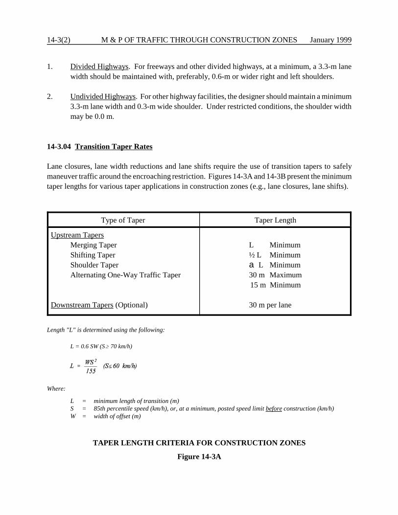
14-3(2) M & P OF TRAFFIC THROUGH CONSTRUCTION ZONES January 1999
1. Divided Highways. For freeways and other divided highways, at a minimum, a 3.3-m lanewidth should be maintained with, preferably, 0.6-m or wider right and left shoulders.
2. Undivided Highways. For other highway facilities, the designer should maintain a minimum3.3-m lane width and 0.3-m wide shoulder. Under restricted conditions, the shoulder widthmay be 0.0 m.
14-3.04 Transition Taper Rates
Lane closures, lane width reductions and lane shifts require the use of transition tapers to safelymaneuver traffic around the encroaching restriction. Figures 14-3A and 14-3B present the minimumtaper lengths for various taper applications in construction zones (e.g., lane closures, lane shifts).
Type of Taper Taper Length
Upstream TapersMerging TaperShifting TaperShoulder TaperAlternating One-Way Traffic Taper
Downstream Tapers (Optional)
L Minimum½ L Minimuma L Minimum30 m Maximum15 m Minimum
30 m per lane
Length "L" is determined using the following:
L = 0.6 SW (SA 70 km/h)
Where:
L = minimum length of transition (m)S = 85th percentile speed (km/h), or, at a minimum, posted speed limit before construction (km/h)W = width of offset (m)
TAPER LENGTH CRITERIA FOR CONSTRUCTION ZONES
Figure 14-3A

January 1999 M & P OF TRAFFIC THROUGH CONSTRUCTION ZONES 14-3(3)
Note: Length “L” is determined from Figure 14-3A.
TAPER LENGTH CRITERIA FOR CONSTRUCTION ZONES(Application)
Figure 14-3B
14-3(4) M & P OF TRAFFIC THROUGH CONSTRUCTION ZONES January 1999
14-3.05 Alignment
Once the design speed is selected for the construction zone, the designer will use the criteria inChapter Two (geometric design of 3R projects) for alignment considerations. Note that, althoughChapter Two applies to the permanent design of non-freeways, the 3R criteria in Chapter Two isapplicable to the design of the construction zones for all facilities. One application of the 3R criteria,for example, will be the minimum radius for maintaining the normal crown section through ahorizontal curve for a given design speed and given (negative) superelevation (see Figure 2-5A).This will then be the minimum radius for a horizontal curve which transitions traffic from themainline to a temporary roadway without superelevation. For low-speed urban streets, the designerwill use Figure 8-3B for the minimum radius for a normal crown section.
14-3.06 Exceptions
It is not Department policy to obtain formal design exceptions for temporary conditions inconstruction zones.
January 1999 M & P OF TRAFFIC THROUGH CONSTRUCTION ZONES 14-4(1)
14-4.0 ROADSIDE SAFETY
Through a construction zone, drivers are often exposed to numerous hazards (e.g., restrictivegeometrics, construction equipment, opposing traffic). The designer must devote special attentionto reducing a motorist’s exposure to these hazards. The following sections offer roadside safetycriteria which apply only to the roadside elements within the construction zone. These criteria donot apply to detours over existing routes.
14-4.01 Warrants for Positive Protection
Positive protection for run-off-the-road vehicles may be warranted in construction zones. Thisdecision will be made on a project-by-project and site-by-site basis. The following factors should beconsidered:
1. duration of construction activity;2. traffic volumes (including seasonal fluctuations);3. nature of hazard (e.g., edge of travel lane drop-offs);4. design speed;5. highway functional class;6. proximity between traffic and construction workers and construction equipment;7. adverse geometrics which may increase the likelihood of run-off-the-road vehicles;8. length and depth of dropoffs;9. length of hazard; and/or10. lane closures or lane transitions.
During the planning and design of a project, careful consideration should be given to traffic controlplan alternatives which do not require the use of temporary barriers. The alternatives includeconstruction of detour roadways, minimizing the exposure time and depth of drop-offs, and providingmaximum separation between traffic and workers.
However, even with proper project planning and design, there will be many instances where barriersare clearly needed. In a barrier system, the greatest hazard occurs at the approach end. To achievethe safest condition, three goals are important:
1. flare the approach end to a location outside the clear zone or as far away from the throughtraffic lanes as practical; and
2. if the approach end cannot be placed outside the clear zone, provide the most crashworthyend treatment as technically and economically feasible; and
14-4(2) M & P OF TRAFFIC THROUGH CONSTRUCTION ZONES January 1999
3. provide adequate delineation in advance of and along the temporary barrier.
Where traffic is directed onto the opposing roadway, the designer should consider the effect this willhave on the operational characteristics of roadside appurtenances. For example, existing trailing endsof unprotected bridge rails may require approach guardrail transitions or impact attenuators, or bluntguardrail terminals may need to be protected with an acceptable end treatment.
14-4.02 Clear Zones
Section 13-2.0 provides the appropriate clear zone values for new construction/reconstructionprojects. For construction zones, the clear zone should be the distances in Section 13-2.0. It isimportant to select the appropriate clear zone based on the construction zone design speed and notthe posted speed. If the recommended clear zone cannot be achieved, the safest end treatmentshould be provided consistent with cost-effectiveness and geometric considerations.
14-4.03 Roadside Barriers
In general, there are two types of roadside barriers — guide railing and temporary precast concretebarrier curb (TPCBC). Design and installation details for temporary guide railing should be the samefor permanent installations; see Chapter Thirteen for additional information. Metal beam rail mustfirst be stiffened before it is attached to TPCBC.
When it has been determined that TPCBC should be used in a work zone, special care must be givento its layout. Although it provides the greatest protection to the work zone, it is also the leastforgiving to the driver. Impact with the blunt end of concrete barrier (including contractor's accessopenings) will result in an intolerable impact, even at low speeds. All barriers will require anappropriate end treatment; see Section 14-4.04.
TPCBC should be extended at an appropriate flare rate to a point beyond the clear zone. The flarerate for TPCBC on freeways is 1:10, and for non-freeways the flare rates should be based on thedesign speed through the work zone. The TPCBC flare rates for non-freeways are shown in Figure14-4A. The designer should meet these flare rates unless extenuating circumstances render theserates impractical (e.g., stop conditions, driveways, intersections).
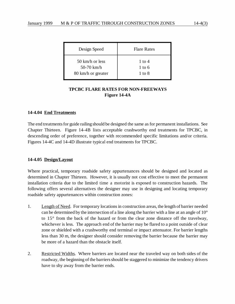
January 1999 M & P OF TRAFFIC THROUGH CONSTRUCTION ZONES 14-4(3)
Design Speed Flare Rates
50 km/h or less50-70 km/h
80 km/h or greater
1 to 41 to 61 to 8
TPCBC FLARE RATES FOR NON-FREEWAYSFigure 14-4A
14-4.04 End Treatments
The end treatments for guide railing should be designed the same as for permanent installations. SeeChapter Thirteen. Figure 14-4B lists acceptable crashworthy end treatments for TPCBC, indescending order of preference, together with recommended specific limitations and/or criteria.Figures 14-4C and 14-4D illustrate typical end treatments for TPCBC.
14-4.05 Design/Layout
Where practical, temporary roadside safety appurtenances should be designed and located asdetermined in Chapter Thirteen. However, it is usually not cost effective to meet the permanentinstallation criteria due to the limited time a motorist is exposed to construction hazards. Thefollowing offers several alternatives the designer may use in designing and locating temporaryroadside safety appurtenances within construction zones:
1. Length of Need. For temporary locations in construction areas, the length of barrier neededcan be determined by the intersection of a line along the barrier with a line at an angle of 10°to 15° from the back of the hazard or from the clear zone distance off the travelway,whichever is less. The approach end of the barrier may be flared to a point outside of clearzone or shielded with a crashworthy end terminal or impact attenuator. For barrier lengthsless than 30 m, the designer should consider removing the barrier because the barrier maybe more of a hazard than the obstacle itself.
2. Restricted Widths. Where barriers are located near the traveled way on both sides of theroadway, the beginning of the barriers should be staggered to minimize the tendency drivershave to shy away from the barrier ends.
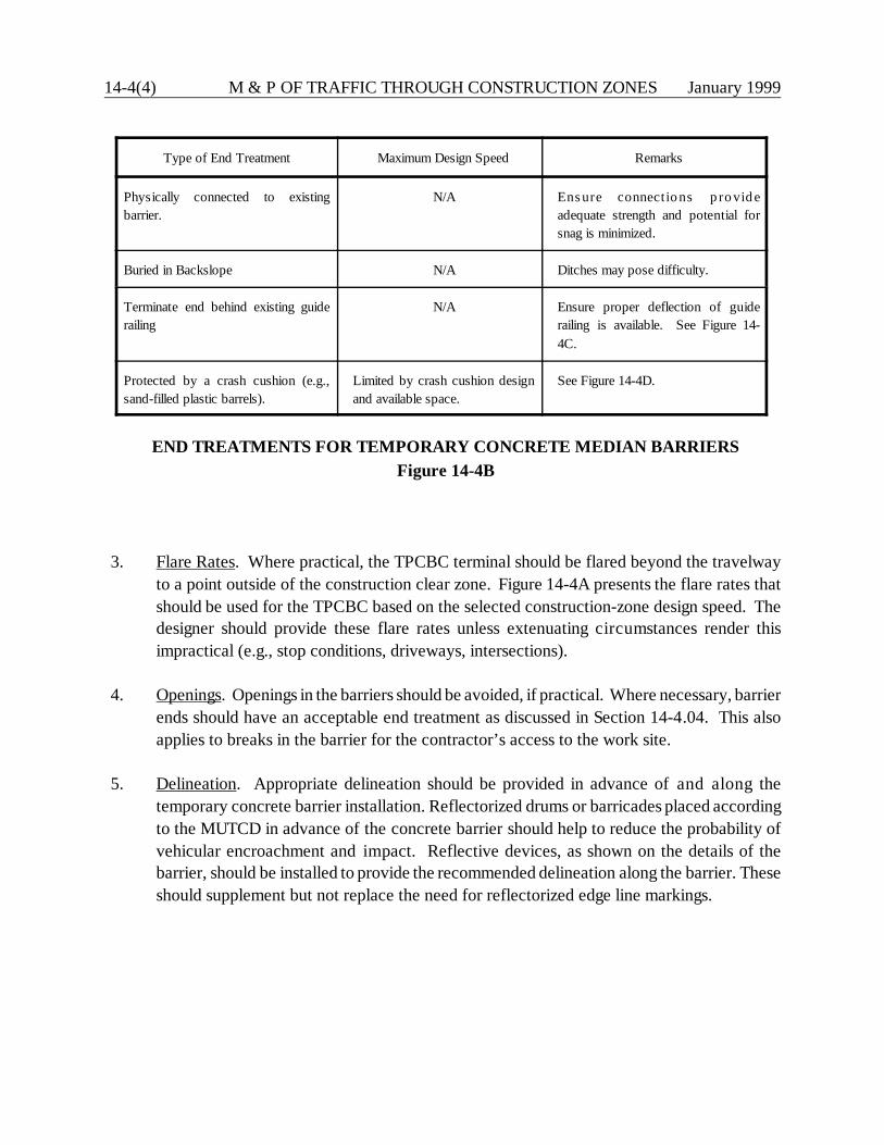
14-4(4) M & P OF TRAFFIC THROUGH CONSTRUCTION ZONES January 1999
Type of End Treatment Maximum Design Speed Remarks
Physically connected to existingbarrier.
N/A Ens ure connectio ns p ro vid eadequate strength and potential forsnag is minimized.
Buried in Backslope N/A Ditches may pose difficulty.
Terminate end behind existing guiderailing
N/A Ensure proper deflection of guiderailing is available. See Figure 14-4C.
Protected by a crash cushion (e.g.,sand-filled plastic barrels).
Limited by crash cushion designand available space.
See Figure 14-4D.
END TREATMENTS FOR TEMPORARY CONCRETE MEDIAN BARRIERSFigure 14-4B
3. Flare Rates. Where practical, the TPCBC terminal should be flared beyond the travelwayto a point outside of the construction clear zone. Figure 14-4A presents the flare rates thatshould be used for the TPCBC based on the selected construction-zone design speed. Thedesigner should provide these flare rates unless extenuating circumstances render thisimpractical (e.g., stop conditions, driveways, intersections).
4. Openings. Openings in the barriers should be avoided, if practical. Where necessary, barrierends should have an acceptable end treatment as discussed in Section 14-4.04. This alsoapplies to breaks in the barrier for the contractor’s access to the work site.
5. Delineation. Appropriate delineation should be provided in advance of and along thetemporary concrete barrier installation. Reflectorized drums or barricades placed accordingto the MUTCD in advance of the concrete barrier should help to reduce the probability ofvehicular encroachment and impact. Reflective devices, as shown on the details of thebarrier, should be installed to provide the recommended delineation along the barrier. Theseshould supplement but not replace the need for reflectorized edge line markings.
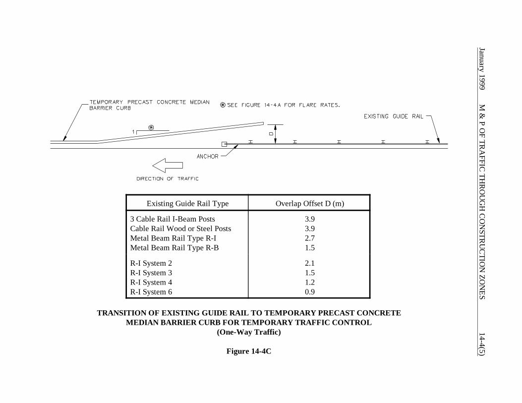
January 1999 M
& P O
F TRA
FFIC TH
RO
UG
H C
ON
STRU
CTIO
N ZO
NES
14-4(5)
Existing Guide Rail Type Overlap Offset D (m)
3 Cable Rail I-Beam PostsCable Rail Wood or Steel PostsMetal Beam Rail Type R-IMetal Beam Rail Type R-B
3.93.92.71.5
R-I System 2R-I System 3R-I System 4R-I System 6
2.11.51.20.9
TRANSITION OF EXISTING GUIDE RAIL TO TEMPORARY PRECAST CONCRETEMEDIAN BARRIER CURB FOR TEMPORARY TRAFFIC CONTROL
(One-Way Traffic)
Figure 14-4C
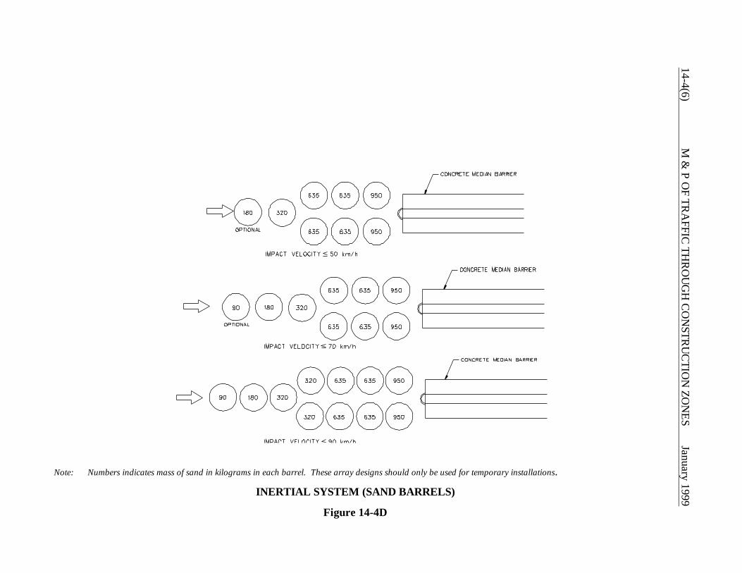
14-4(6)M
& P O
F TRA
FFIC TH
RO
UG
H C
ON
STRU
CTIO
N ZO
NES
January 1999
Note: Numbers indicates mass of sand in kilograms in each barrel. These array designs should only be used for temporary installations.
INERTIAL SYSTEM (SAND BARRELS)
Figure 14-4D

January 1999 M & P OF TRAFFIC THROUGH CONSTRUCTION ZONES 14-5(1)
14-5.0 REFERENCES
1. Manual on Uniform Traffic Control Devices, Part VI, FHWA, 1993.
2. Planning and Scheduling Work Zone Traffic Control, FHWA-IP-81-6, FHWA, 1981.
3. A Policy on Geometric Design of Highways and Streets, AASHTO 1994.
4. Roadside Design Guide, AASHTO 1996.

14-5(2) M & P OF TRAFFIC THROUGH CONSTRUCTION ZONES January 1999

January 1999 SPECIAL DESIGN ELEMENTS 15-i
Chapter Fifteen
SPECIAL DESIGN ELEMENTS
Table of Contents
Page
15-1.0 ACCESSIBILITY FOR HANDICAPPED INDIVIDUALS . . . . . . . . . . . . . . . 15-1(1)
15-1.01 Buildings . . . . . . . . . . . . . . . . . . . . . . . . . . . . . . . . . . . . . . . . . . . . . 15-1(1) 15-1.02 Bus Stops . . . . . . . . . . . . . . . . . . . . . . . . . . . . . . . . . . . . . . . . . . . . 15-1(1) 15-1.03 Parking . . . . . . . . . . . . . . . . . . . . . . . . . . . . . . . . . . . . . . . . . . . . . . 15-1(2)
15-1.03.01 Off-Street Parking . . . . . . . . . . . . . . . . . . . . . . . . . . 15-1(2) 15-1.03.02 On-Street Parking . . . . . . . . . . . . . . . . . . . . . . . . . . 15-1(5)
15-1.04 Accessible Route . . . . . . . . . . . . . . . . . . . . . . . . . . . . . . . . . . . . . . . 15-1(6) 15-1.05 Sidewalks . . . . . . . . . . . . . . . . . . . . . . . . . . . . . . . . . . . . . . . . . . . . 15-1(8)
15-1.05.01 Criteria for Accessible Routes . . . . . . . . . . . . . . . . . 15-1(8) 15-1.05.02 Criteria for Non-Accessible Routes . . . . . . . . . . . . . 15-1(9)
15-1.06 Stairs . . . . . . . . . . . . . . . . . . . . . . . . . . . . . . . . . . . . . . . . . . . . . . . . 15-1(10)15-1.07 Ramps . . . . . . . . . . . . . . . . . . . . . . . . . . . . . . . . . . . . . . . . . . . . . . . 15-1(10)15-1.08 Curb Ramps . . . . . . . . . . . . . . . . . . . . . . . . . . . . . . . . . . . . . . . . . . 15-1(13)
15-1.08.01 General . . . . . . . . . . . . . . . . . . . . . . . . . . . . . . . . . . 15-1(13)15-1.08.02 Location . . . . . . . . . . . . . . . . . . . . . . . . . . . . . . . . . 15-1(13)15-1.08.03 Crossing Controls . . . . . . . . . . . . . . . . . . . . . . . . . . 15-1(14)15-1.08.04 Types . . . . . . . . . . . . . . . . . . . . . . . . . . . . . . . . . . . 15-1(16)
15-1.09 Pedestrian Overpasses and Underpasses . . . . . . . . . . . . . . . . . . . . . 15-1(19)
15-2.0 COMMUTER LOTS . . . . . . . . . . . . . . . . . . . . . . . . . . . . . . . . . . . . . . . . . . . . 15-2(1)
15-2.01 General . . . . . . . . . . . . . . . . . . . . . . . . . . . . . . . . . . . . . . . . . . . . . . 15-2(1) 15-2.02 Layout . . . . . . . . . . . . . . . . . . . . . . . . . . . . . . . . . . . . . . . . . . . . . . . 15-2(1)
15-2.02.01 Entrances and Exits . . . . . . . . . . . . . . . . . . . . . . . . . 15-2(1) 15-2.02.02 Traffic Circulation . . . . . . . . . . . . . . . . . . . . . . . . . . . 15-2(2) 15-2.02.03 Pedestrian and Bicyclist Considerations . . . . . . . . . . 15-2(2)
15-2.02.04 Accessibility for Handicapped Individuals . . . . . . . . . 15-2(2)
15-2.03 Design Elements . . . . . . . . . . . . . . . . . . . . . . . . . . . . . . . . . . . . . . . . 15-2(2)
15-ii SPECIAL DESIGN ELEMENTS January 1999
Table of Contents(Continued)
Page
15-3.0 BUS STOPS AND TURNOUTS . . . . . . . . . . . . . . . . . . . . . . . . . . . . . . . . . . . 15-3(1)
15-3.01 Location . . . . . . . . . . . . . . . . . . . . . . . . . . . . . . . . . . . . . . . . . . . . . 15-3(1)
15-3.01.01 Bus Stops . . . . . . . . . . . . . . . . . . . . . . . . . . . . . . . . 15-3(1) 15-3.01.02 Bus Turnouts . . . . . . . . . . . . . . . . . . . . . . . . . . . . . . 15-3(1)
15-3.02 Design . . . . . . . . . . . . . . . . . . . . . . . . . . . . . . . . . . . . . . . . . . . . . . . 15-3(2)
15-3.02.01 Bus Stops . . . . . . . . . . . . . . . . . . . . . . . . . . . . . . . . 15-3(2) 15-3.02.02 Bus Turnouts . . . . . . . . . . . . . . . . . . . . . . . . . . . . . . 15-3(2) 15-3.02.03 Bus Stop Pads . . . . . . . . . . . . . . . . . . . . . . . . . . . . . 15-3(5) 15-3.02.04 Bus Shelters . . . . . . . . . . . . . . . . . . . . . . . . . . . . . . . 15-3(5)
15-4.0 BIKEWAYS . . . . . . . . . . . . . . . . . . . . . . . . . . . . . . . . . . . . . . . . . . . . . . . . . . 15-4(1)
15-4.01 Bikeway Classifications . . . . . . . . . . . . . . . . . . . . . . . . . . . . . . . . . . 15-4(1) 15-4.02 Warrants . . . . . . . . . . . . . . . . . . . . . . . . . . . . . . . . . . . . . . . . . . . . . 15-4(1) 15-4.03 Bikeway Design Elements . . . . . . . . . . . . . . . . . . . . . . . . . . . . . . . . . 15-4(2)
15-5.0 LANDSCAPING . . . . . . . . . . . . . . . . . . . . . . . . . . . . . . . . . . . . . . . . . . . . . . . 15-5(1)
15-5.01 General Benefits . . . . . . . . . . . . . . . . . . . . . . . . . . . . . . . . . . . . . . . . 15-5(1) 15-5.02 Landscaping Policies . . . . . . . . . . . . . . . . . . . . . . . . . . . . . . . . . . . . 15-5(2)
15-5.02.01 Planting Policy . . . . . . . . . . . . . . . . . . . . . . . . . . . . . 15-5(2) 15-5.02.02 Protection of Existing Vegetation . . . . . . . . . . . . . . . 15-5(2) 15-5.02.03 Turf Establishment, Topsoil and Sodding . . . . . . . . . . 15-5(2)
15-6.0 FENCING . . . . . . . . . . . . . . . . . . . . . . . . . . . . . . . . . . . . . . . . . . . . . . . . . . . . 15-6(1)
15-6.01 General Warrants and Location . . . . . . . . . . . . . . . . . . . . . . . . . . . . 15-6(1) 15-6.02 Freeways . . . . . . . . . . . . . . . . . . . . . . . . . . . . . . . . . . . . . . . . . . . . . 15-6(2) 15-6.03 Unlimited Access Highways . . . . . . . . . . . . . . . . . . . . . . . . . . . . . . . 15-6(3) 15-6.04 Fencing and Railings on Highway Structures . . . . . . . . . . . . . . . . . . . 15-6(3)
15-6.04.01 General . . . . . . . . . . . . . . . . . . . . . . . . . . . . . . . . . . 15-6(3) 15-6.04.02 Highway Overpasses with Sidewalks . . . . . . . . . . . . 15-6(4) 15-6.04.03 Highway Overpasses without Sidewalks . . . . . . . . . . 15-6(4) 15-6.04.04 Stream and Wetland Overpasses . . . . . . . . . . . . . . . 15-6(4) 15-6.04.05 Railroad Overpasses . . . . . . . . . . . . . . . . . . . . . . . . 15-6(5) 15-6.04.06 Pedestrian Overpasses . . . . . . . . . . . . . . . . . . . . . . . 15-6(5)
January 1999 SPECIAL DESIGN ELEMENTS 15-iii
Table of Contents(Continued)
Page
15-6.04.07 Walls . . . . . . . . . . . . . . . . . . . . . . . . . . . . . . . . . . . . 15-6(5) 15-6.04.08 Railing and Fencing at Lighting and Signing
Standards . . . . . . . . . . . . . . . . . . . . . . . . . . . . . . . . 15-6(6)
15-6.05 Fencing Delineation on Contract Plans . . . . . . . . . . . . . . . . . . . . . . . 15-6(6)
15-7.0 NOISE BARRIER IMPACTS . . . . . . . . . . . . . . . . . . . . . . . . . . . . . . . . . . . . . . 15-7(1)
15-7.01 Roadside Safety . . . . . . . . . . . . . . . . . . . . . . . . . . . . . . . . . . . . . . . . 15-7(1) 15-7.02 Sight Distance . . . . . . . . . . . . . . . . . . . . . . . . . . . . . . . . . . . . . . . . . 15-7(1) 15-7.03 Right-of-Way . . . . . . . . . . . . . . . . . . . . . . . . . . . . . . . . . . . . . . . . . . 15-7(1) 15-7.04 Interference with Roadside Appurtenances . . . . . . . . . . . . . . . . . . . . 15-7(1) 15-7.05 Additional Design Criteria . . . . . . . . . . . . . . . . . . . . . . . . . . . . . . . . . 15-7(2)
15-8.0 REFERENCES . . . . . . . . . . . . . . . . . . . . . . . . . . . . . . . . . . . . . . . . . . . . . . . . . 15-8(1)

15-iv SPECIAL DESIGN ELEMENTS January 1999
January 1999 SPECIAL DESIGN ELEMENTS 15-1(1)
Chapter Fifteen
SPECIAL DESIGN ELEMENTS
15-1.0 ACCESSIBILITY FOR HANDICAPPED INDIVIDUALS
Many highway elements can affect the accessibility and mobility of handicapped individuals. Theseinclude sidewalks, parking lots, buildings at transportation facilities, overpasses and underpasses.The Department's accessibility criteria complies with the 1990 Americans with Disabilities Act(ADA) and the General Statutes of Connecticut (CGS). The following sections present accessibilitycriteria which are based on information presented in the ADA Accessibility Guidelines for Buildingsand Facilities (ADA Guidelines). Designers are required to meet the criteria presented in thefollowing sections. Where other agencies or local codes require standards which exceed the ADAGuidelines, then the stricter criteria may be required. This will be determined on a case-by-casebasis.
15-1.01 Buildings
ADA Reference: Section 4.1
For interior accessibility criteria in all buildings, airport terminals, rest areas, weigh stations andtransit stations (e.g., stations for intercity bus, intercity rail, high-speed rail and other fixed guidewaysystems), the accessibility criteria set forth in the ADA Guidelines shall apply. The designer shouldreview the ADA Guidelines to determine the appropriate accessibility requirements for buildinginteriors, including rest rooms, drinking fountains, elevators, telephones, etc.
15-1.02 Bus Stops
ADA Reference: Section 10.2
The following accessibility criteria apply to the construction of bus stops:
1. Bus Stop Pads. New bus stop pads constructed to be used in conjunction with a lift or rampshall meet the following criteria:
a. A firm stable surface must be provided.
15-1(2) SPECIAL DESIGN ELEMENTS January 1999
b. It must have a minimum clear length of 2440 mm (measured from the curb orroadway edge) and minimum clear width of 1525 mm (measured parallel to theroadway) depending on the legal or site constraints.
c. It must be connected to streets, sidewalks or pedestrian paths by at least oneaccessible route.
d. The slope of pad parallel to the roadway must be the same as the roadway to themaximum extent practical.
e. For drainage purposes, a maximum cross slope of 2% perpendicular to the roadwayis allowable.
2. Bus Shelters. Where new or replaced bus shelters are provided, they must be installed orpositioned to permit a wheelchair user to enter from the public way and reach a locationwithin the shelter having a minimum clear floor area of 760 mm by 1220 mm. An accessibleroute shall be provided from the shelter to the boarding area.
3. Signing. All new bus route identification signs should be sized based on the maximumdimensions permitted by local, state or federal regulations or ordinances. The signs shallhave an eggshell, matte or other non-glare finish. The characters or symbols shall contrastwith their background (i.e., light characters on a dark background or dark characters on alight background).
15-1.03 Parking
ADA Reference: Section 4.1.2
Connecticut General Statutes: CGS 14-253a “Parking privileges for blind or handicapped persons.Identification card. License plates. Parking spaces. Penalty.”
15-1.03.01 Off-Street Parking
ADA Reference: Section 4.1.2 and 4.6
The following criteria apply to off-street handicapped parking spaces:
1. Minimum Number. Figure 15-1A provides the criteria for the minimum number of accessiblespaces. A typical handicapped stall layout is shown in Figure 15-1B.
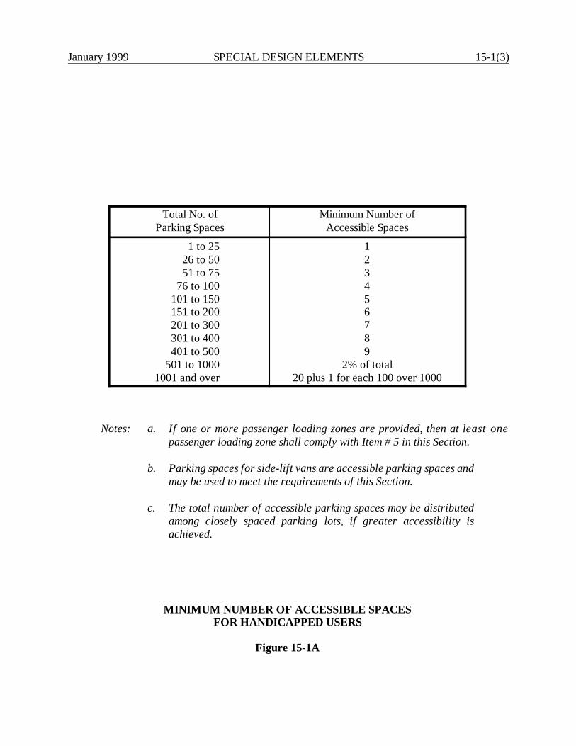
January 1999 SPECIAL DESIGN ELEMENTS 15-1(3)
Total No. ofParking Spaces
Minimum Number ofAccessible Spaces
1 to 2526 to 5051 to 75
76 to 100101 to 150151 to 200201 to 300301 to 400401 to 500
501 to 10001001 and over
123456789
2% of total20 plus 1 for each 100 over 1000
Notes: a. If one or more passenger loading zones are provided, then at least onepassenger loading zone shall comply with Item # 5 in this Section.
b. Parking spaces for side-lift vans are accessible parking spaces andmay be used to meet the requirements of this Section.
c. The total number of accessible parking spaces may be distributedamong closely spaced parking lots, if greater accessibility isachieved.
MINIMUM NUMBER OF ACCESSIBLE SPACESFOR HANDICAPPED USERS
Figure 15-1A
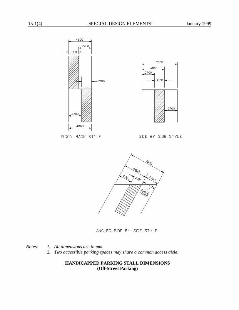
15-1(4) SPECIAL DESIGN ELEMENTS January 1999
Notes: 1. All dimensions are in mm.2. Two accessible parking spaces may share a common access aisle.
HANDICAPPED PARKING STALL DIMENSIONS(Off-Street Parking)
January 1999 SPECIAL DESIGN ELEMENTS 15-1(5)
2. Location. Parking spaces for disabled individuals and accessible passenger loadingzones that serve a particular building shall be the spaces or zones closest to thenearest accessible entrance on an accessible route. In separate parking structures orlots that do not serve a particular building, parking spaces for disabled individualsshall be located on the shortest possible circulation route to an accessible pedestrianentrance of the parking facility. In buildings with multiple access entrances withadjacent parking, accessible parking spaces shall be dispersed and located closest tothe accessible entrances.
3. Signing. Parking spaces for the handicapped shall be designated by above-grade signs withwhite lettering against a blue background and shall bear the international symbol of access(see MUTCD), and the words “Handicapped Parking State Permit Required” and “ViolatorsWill Be Fined.”. The sign shall not be obscured by a vehicle parked in the space.
4. Dimensions. The parking spaces designated for the handicapped shall be at a minimum 4800-mm wide which includes a 2100-mm minimum access aisle, or the space should be parallelto a sidewalk on a public highway. Parking access aisles shall be part of an accessible routeto the building or facility entrance. Parked vehicular overhangs shall not reduce the clearwidth of an accessible circulation route. Parking spaces and access aisles shall be level withsurface slopes not exceeding 2% in all directions. The Division of Traffic Engineering willdetermine the striping plan for the handicapped parking spaces.
5. Passenger Loading Zones. Passenger loading zones shall provide an access aisle at least1525-mm wide and 6100-mm long adjacent and parallel to the vehicular pull-up space. Ifthere are curbs between the access aisle and the vehicular pull-up space, then a curb rampcomplying with Section 15-1.08 shall be provided. Vehicular standing spaces and accessaisles shall be essentially level. Surface slopes shall not exceed 2% in all directions.
6. Parking Garages (Vertical Clearances). The designer must meet the requirements of theConnecticut General Statutes, CGS 14-253a for any parking garages: “Any parking garageor terminal constructed on and after October 1, 1985, shall have nine feet six inches verticalclearance (2895 mm) at its entrance and along the route to at least two parking spaces whichconform with the requirements of subsection (f) of this statute and which have nine feet six(2895 mm) inches vertical clearance.” The criteria in Item #2 “Location,” #3 “Signing,” and#4 “Dimensions” meet the requirements of subsection (f) of CGS 14-253a.
15-1.03.02 On-Street Parking
Where new on-street paid or time-limited parking is provided and designated in districts zoned forbusiness uses, the designer should consider the following accessibility criteria for the on-streetparking:
15-1(6) SPECIAL DESIGN ELEMENTS January 1999
1. Minimum Number. Figure 15-1A provides the criteria for the minimum number of on-streetaccessibility spaces.
2. Location. On-street accessibility parking spaces will be dispersed throughout the projectarea. To the maximum extent feasible, accessible on-street parking should be located in levelareas.
3. Dimensions. At a minimum, a 1525-mm wide perpendicular access aisle must be providedat the head or foot of the parking space. This is illustrated in Figure 15-1C. The travel laneshall not encroach into the access aisle.
4. Signing. Parking spaces for the handicapped shall be designated by above-ground signs withwhite lettering against a blue background, and the signs shall bear the international symbolof access (see MUTCD) and the words “Handicapped Parking State Permit Required” and“Violators Will Be Fined.” These signs will be located to be visible from a driver's seat.
5. Curb Ramps. If there are curbs next to an on-street accessible parking space, then a curbramp complying with Section 15-1.08 shall be provided. Access parking spaces adjacent tointersections may be served by the sidewalk curb ramp at the intersection, provided that thepath of travel from the access aisle to the curb ramp is within the pedestrian crossing area.
6. Parking Meters. Where provided, parking meter controls shall be a maximum of 1220 mmabove the sidewalk or pedestrian circulation path. Controls and operating mechanisms shallbe operable with one hand and shall not require tight grasping, pinching or twisting of thewrist. The force required to activate controls shall be no greater than 22.2 N. A firm, stableand slip-resistant area (760 mm by 1220 mm), with the least possible slope, shall be providedat the controls and shall be connected to the sidewalk by a continuous passage that is aminimum of 915-mm wide.
15-1.04 Accessible Route
ADA Reference: Section 4.3
An accessible route is a continuous, unobstructed path connecting all accessible elements and spacesin a building, facility or site. A "site" is defined as a parcel of land bounded by a property line or adesignated portion of a public right-of-way. A "facility" is defined as all or any portion of buildings,structures, site improvements, complexes, equipment, roads, walks, passageways, parking lots, orother real or personal property on a site. Interior accessible routes may include corridors, floors,ramps, elevators, lifts and clear floor space at fixtures. Exterior accessible routes may includeparking access aisles, curb ramps, crosswalks at vehicular ways, walks, ramps and lifts.
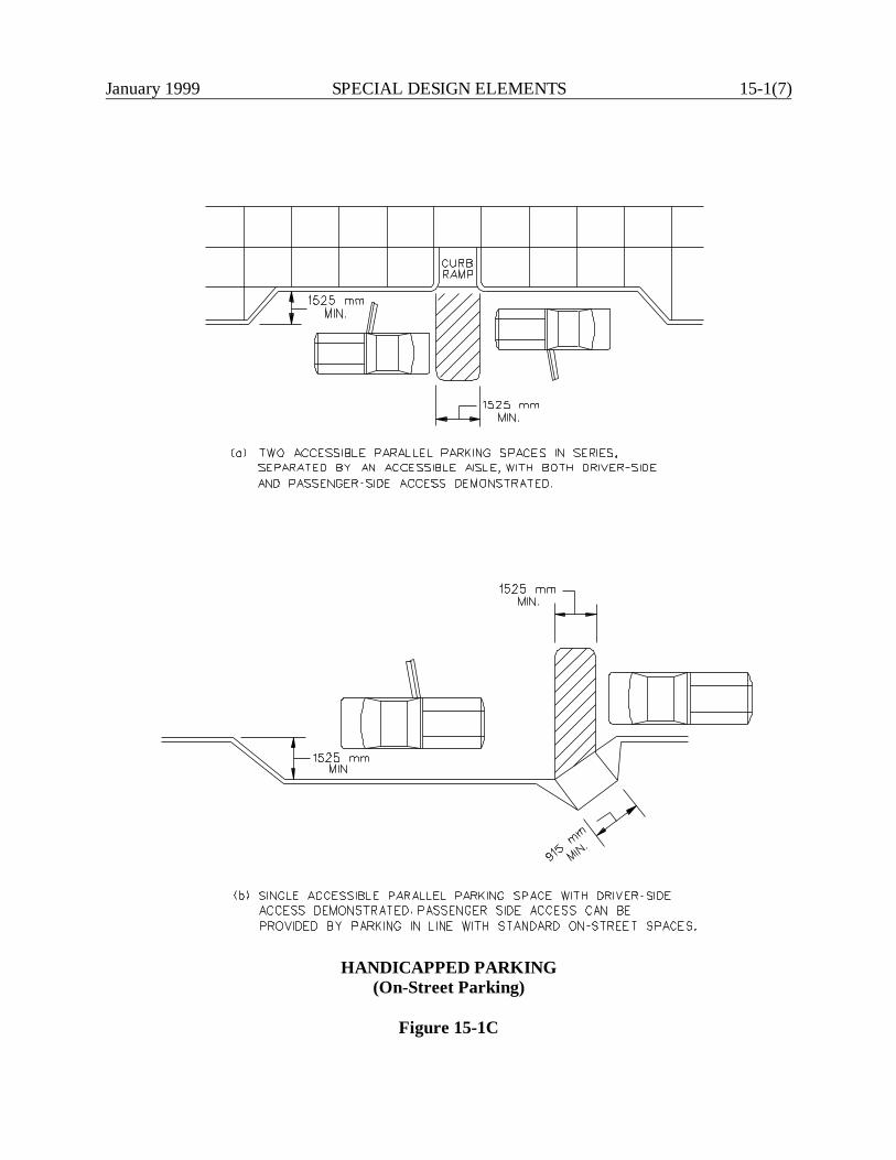
January 1999 SPECIAL DESIGN ELEMENTS 15-1(7)
HANDICAPPED PARKING(On-Street Parking)
Figure 15-1C
15-1(8) SPECIAL DESIGN ELEMENTS January 1999
Accessible routes must be provided as follows:
1. At least one accessible route within the boundary of the site shall be provided from publictransportation stops, accessible parking, accessible passenger loading zones, and publicstreets or sidewalks to the accessible building entrance they serve. The accessible routeshall, to the maximum extent feasible, coincide with the route for the general public.
2. At least one accessible route shall connect accessible buildings, facilities, elements, andspaces that are on the same site.
3. At least one accessible route shall connect accessible buildings or facility entrances with allaccessible spaces and elements and with all accessible dwelling units within the building orfacility.
For highway projects, the application of the accessible route criteria applies to definitive sites whichare related to highway purposes. These include rest areas, recreational areas, park-and-ride lots, etc.Section 15-1.05 provides the accessibility requirements for sidewalks. Most sidewalks along publicright-of-way are considered non-accessible.
15-1.05 Sidewalks
Section 10-2.01 presents the Department's warrants and design criteria for sidewalks. In addition,all sidewalks must comply with the ADA Guidelines presented in the following sections.
15-1.05.01 Criteria for Accessible Routes
ADA Reference: Various.
For sidewalks on accessible routes, the following accessibility criteria shall be met:
1. Width. The minimum clear width shall be 915 mm, except at doors which may have aminimum width of 815 mm.
2. Passing Space. If the sidewalk has less than 1525-mm clear width, then passing spaces atleast 1525 mm by 1525 mm shall be located at reasonable intervals not to exceed 61 m. AT-intersection between two walks is an acceptable passing space. Paved driveways alsoprovide acceptable passing space in residential areas.
January 1999 SPECIAL DESIGN ELEMENTS 15-1(9)
3. Surface. All sidewalk surfaces shall be stable, firm and slip resistant. The longitudinalgradient should be flush and free of abrupt changes. However, changes in level up to 6 mmmay be vertical and without edge treatment. Changes in level between 6 mm and 13 mmshall be beveled with a slope no greater than 50%. Changes greater than 13 mm shall beaccommodated with a ramp (see Section 15-1.07).
Gratings should not be placed within the walking surface. If, however, gratings are locatedin walking surfaces, then they shall have spaces no greater than 13-mm wide in one direction.If gratings have elongated openings, then they shall be placed so that the long dimension isperpendicular to the dominant direction of travel.
4. Slope. The sidewalk cross slope shall not exceed 2%. If the longitudinal gradient exceeds 5%,the sidewalk must meet the accessibility criteria for ramps (see Section 15-1.07).
5. Protruding Objects. Objects projecting from walls (e.g., signs, telephones, canopies) withtheir leading edges between 685 mm and 2030 mm above the finished sidewalk shall notprotrude more than 100 mm into any portion of the sidewalk. Freestanding objects mountedon posts or pylons may overhang their mountings up to a maximum of 305 mm when locatedbetween 685 mm and 2030 mm above the sidewalk or ground surface. Protruding objectsless than 685 mm or greater than 2030 mm may protrude any amount provided that theeffective width of the sidewalk is maintained. Where the vertical clearance is less than 2030mm, a barrier shall be provided to warn the blind or visually-impaired person.
6. Separation. Sidewalks will be separated from roadways by curbs, snow shelf or otherbarriers, which will be continuous except where interrupted by driveways, alleys orconnections to accessible elements.
7. Bus Stops. Where bus passenger loading areas or bus shelters are provided on or adjacentto sidewalks, they must comply with the criteria in Section 15-1.02.
8. Curb Ramps. All curb ramps on an accessible route must comply with the criteria in Section15-1.08.
15-1.05.02 Criteria for Non-Accessible Routes
In general, sidewalks on non-accessible routes should meet the criteria presented in Section15-1.05.01. However, some flexibility is required to meet the adjacent roadway conditions and toprovide practical designs. The criteria in Section 15-1.05.01 should be implemented, unless notedas follows:
15-1(10) SPECIAL DESIGN ELEMENTS January 1999
1. Slopes. The flattest longitudinal slope practical should be provided. Preferably, thelongitudinal slope should not exceed 8%. Sidewalk slopes 5% or greater do not require theuse of handrails as defined in Section 15-1.07. Cross slopes greater than 2% may be usedprovided adjacent portions are smoothly blended.
2. Stairs. Sidewalks with stairs are allowed on non-accessible routes, provided an unobstructedroute is available between accessible entrances. Section 15-1.06 presents criteria for stairs.
3. Separation. Sidewalks adjacent to the curb or roadway may be offset to avoid a non-conforming cross slope at driveway aprons by diverting the sidewalk around the apron.
4. Protruding Objects. Objects on or along a sidewalk which are not fixed, such as newspapervending machines, trash receptacles, etc., are not subject to the ADA Guidelines.
15-1.06 Stairs
ADA Reference: Section 4.9
Stairs shall not be part of an exterior accessible route because they cannot be safely negotiated byindividuals in wheelchairs. Where stairs are used, they should be designed to be accessible by otherhandicapped individuals. Therefore, the design of stairs must comply with Section 4.9 of the ADAGuidelines and the Connecticut Standard Sheets. This includes the provision of handrails.
15-1.07 Ramps
ADA Reference: Sections 4.1.6, 4.8 and 4.26
Any part of an accessible route with a slope greater than 5% shall be considered a ramp and shallconform to the ADA Guidelines. This includes the provision of handrails. The following criteriamust be met for ramps on accessible routes:
1. Slope and Rise. The least possible slope should be used for any ramp. Figure 15-1Dprovides the maximum allowable ramp slopes for new construction. Curb ramps and rampsto be constructed on existing sites or in existing buildings or facilities may have slopes andrises as shown in Figure 15-1E, if space limitations prohibit the use of a 1:12 slope or less.
2. Width. The minimum clear width of a ramp shall be 915 mm.
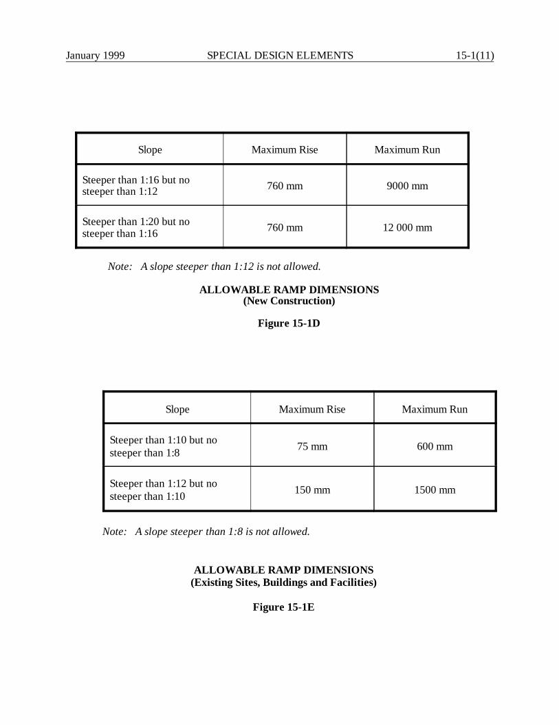
January 1999 SPECIAL DESIGN ELEMENTS 15-1(11)
Slope Maximum Rise Maximum Run
Steeper than 1:10 but nosteeper than 1:8 75 mm 600 mm
Steeper than 1:12 but nosteeper than 1:10 150 mm 1500 mm
Note: A slope steeper than 1:8 is not allowed.
ALLOWABLE RAMP DIMENSIONS(Existing Sites, Buildings and Facilities)
Figure 15-1E
Slope Maximum Rise Maximum Run
Steeper than 1:16 but nosteeper than 1:12 760 mm 9000 mm
Steeper than 1:20 but nosteeper than 1:16 760 mm 12 000 mm
Note: A slope steeper than 1:12 is not allowed.
ALLOWABLE RAMP DIMENSIONS(New Construction)
Figure 15-1D

15-1(12) SPECIAL DESIGN ELEMENTS January 1999
3. Landings. Ramps shall have level landings at the bottom and top of each run. Landings shallhave the following features:
a. The landing shall be at least as wide as the ramp run leading to it.
b. The landing length shall be a minimum of 1525 mm clear.
c. If ramps change direction at landings, the minimum landing size shall be 1525 mm by1525 mm.
4. Handrails. If a ramp run has a rise greater than 150 mm or a horizontal projection greaterthan 1830 mm, then it shall have handrails on both sides. Handrails are not required on curbramps. Handrails shall have the following features:
a. Handrails shall be provided along both sides of ramp segments. The inside handrailon switchback or dogleg ramps shall be continuous.
b. If handrails are not continuous, they shall extend at least 305 mm beyond the top andbottom of the ramp segment and shall be parallel with the floor or ground surface.
c. The clear space between the handrail and the wall shall be 40 mm.
d. Gripping surfaces shall be continuous.
e. Top of handrail gripping surfaces shall be mounted between 865 mm and 965 mmabove ramp surfaces.
f. Ends of handrails shall be either rounded or returned smoothly to floor, wall or post.
g. Handrails shall not rotate within their fittings.
5. Cross Slope and Surfaces. The cross slope of ramp surfaces shall be no greater than 2%.Ramp surfaces shall comply with the criteria for "Surface" for sidewalks (Section 15-1.05).
6. Edge Protection. Ramps and landings with dropoffs shall have curbs, walls, railings orprojecting surfaces that prevent people from slipping off the ramp. Curbs shall be aminimum of 50 mm high.
7. Outdoor Conditions. Outdoor ramps and their approaches shall be designed so that waterwill not accumulate on walking surfaces.
January 1999 SPECIAL DESIGN ELEMENTS 15-1(13)
15-1.08 Curb Ramps
ADA Reference: Section 4.7
Connecticut General Statutes: CGS 7-118a
15-1.08.01 General
“Curb cuts” and “curb ramps” are terms which each describe the treatment at intersections forgradually lowering the elevation of sidewalks with curbs to the elevation of the street surface. Theterm “curb ramps” will be used in this Manual.
All curbs and sidewalks shall be designed with curb ramps at all pedestrian crosswalks to provideadequate and reasonable access for the safe and convenient movement of physically handicappedpersons. This applies to new construction, reconstruction, 3R and spot improvement projects. Forthe purpose of this section, a pedestrian crosswalk is defined as that portion of a highway or streetordinarily included within the prolongation or connections of lateral lines of sidewalks atintersections. It also includes any portion of a highway or street distinctly indicated as a crossing forpedestrians by lines or other markings on the surface, except such prolonged or connecting linesfrom an alley across a street.
15-1.08.02 Location
When determining the need for a curb ramp, the designer should consider the following:
1. If at least one curb will be disturbed by construction at an existing intersection, then curbramps shall be constructed at all crosswalks which extend from a paved sidewalk in thatintersection.
2. For all projects, curb ramps will be constructed at all crosswalks which provide pedestrianaccess in that intersection and will be provided on all corners. At T-intersections, thedesigner must ensure that curb ramps are located on the side opposite the minor intersectingroad.
3. Opposing ramps must always be provided on adjacent legs of an intersection even if outsideproject limits.
4. Curb ramps shall be positioned so as not to cause a safety hazard for blind pedestrians.
5. Curb ramps shall be located or protected to prevent their obstruction by parked vehicles.

15-1(14) SPECIAL DESIGN ELEMENTS January 1999
6. Curb ramps at marked crossings shall be wholly contained within the markings, excludingany flared sides.
7. A diagonal curb ramp shall be wholly contained within the painted markings, including anyflared sides. There shall be at least 610 mm of full-height curb within the crosswalk. Inaddition, there shall be at least 1220 mm between the gutter line and the corner of the twointersecting crosswalks. See Figure 15-1F for an illustration of these criteria.
8. The function of the curb ramp must not be compromised by other highway features (e.g.,guide rail, catch basins, utility poles, signs).
9. Curb ramps are required at all curbed intersections with sidewalks or along all accessibleroutes.
10. The location of the curb ramp must be consistent with the operation of pedestrian-actuatedtraffic signals, if present. In addition, a pedestrian push-button must be located so it can bereached by wheelchair-bound individuals.
11. The designer will provide the Division of Traffic Engineering with a set of plans at thepreliminary design stage and before the preliminary design review. The Division of TrafficEngineering, in its review, will determine the need and location of mid-block curb ramps.These recommendations will be incorporated into the design before the preliminary designreview. In addition, the Division of Traffic Engineering will be notified of any geometricchanges which will impact the location of any curb ramp included in the preliminary designreview.
15-1.08.03 Crossing Controls
If a pedestrian crosswalk and curb ramp are present at an intersection with a traffic signal that haspedestrian detectors (push buttons), the following will apply:
1. Location. Controls shall be located as close as practical to the curb ramp and, to themaximum extent feasible, shall permit operation from a level area immediately adjacent tothe controls.
2. Surface. A firm, stable and slip-resistant area, a minimum of 915 m by 1220 mm, shall beprovided to allow a forward or parallel approach to the controls.
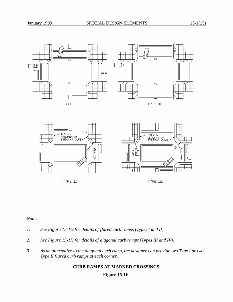
January 1999 SPECIAL DESIGN ELEMENTS 15-1(15)
Notes:
1. See Figure 15-1G for details of flared curb ramps (Types I and II).
2. See Figure 15-1H for details of diagonal curb ramps (Types III and IV).
3. As an alternative to the diagonal curb ramp, the designer can provide two Type I or twoType II flared curb ramps at each corner.
CURB RAMPS AT MARKED CROSSINGS
Figure 15-1F
15-1(16) SPECIAL DESIGN ELEMENTS January 1999
15-1.08.04 Types
Figure 15-1F illustrates the two basic types of curb ramps — flared (Type I and II) and diagonal(Type III and IV). Details for the construction of flared curb ramps are provided in Figure 15-1Gand for diagonal curb ramps in Figure 15-1H.
The following provides several suggestions for selecting the appropriate curb ramp:
1. Crosswalk Markings and Stop Bars. The placement of curb ramps affects the placement ofcrosswalk markings and stop bars. Conversely, the location of existing crosswalk markingsand stop bars affect the placement of curb ramps. Some of the crosswalk markingconstraints are shown in Figure 15-1F and in the Connecticut Standard Sheets. The MUTCDcontains additional constraints on crosswalk markings and stop bar placement.
2. Obstructions. It is desirable to move any obstructions from curb ramps whenever practical.When this is not practical, the direction of traffic relative to the placement of the curb rampmust be considered. It is important that drivers can see the handicapped person using thecurb ramp.
3. Diagonal Curb Ramps. The usage of a diagonal curb ramp should be avoided wheneverpractical due to its effect on the crosswalk width. It is preferable to use the straight curbramp or several straight ramps rather than to use a diagonal curb ramp.
4. Islands. Any raised islands in a pedestrian crosswalk shall be cut through level with thestreet or have curb ramps at both sides and a level area at least 1220-mm long in the part ofthe island intersected by the crossing.
5. Material. Regardless of the type of pavement of the adjacent sidewalk, all curb ramps shallbe constructed of portland cement concrete. Also, all curb ramps shall be constructed inaccordance with the details of the Connecticut Standard Sheets for concrete sidewalk,except for the ramp which will have a textured and non-slip surface.
6. Specifications. Curb ramps shall be constructed, measured and paid for as concretesidewalks, as referred to in the Department’s Standard Specifications for Roads, Bridgesand Incidental Construction, latest issue.

January 1999 SPECIAL DESIGN ELEMENTS 15-1(17)
FLARED CURB RAMPS
Figure 15-1G
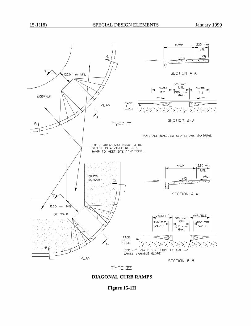
15-1(18) SPECIAL DESIGN ELEMENTS January 1999
DIAGONAL CURB RAMPS
Figure 15-1H
January 1999 SPECIAL DESIGN ELEMENTS 15-1(19)
15-1.09 Pedestrian Overpasses and Underpasses
ADA Reference: Various
When deciding where to locate a pedestrian crossing, the highway and structure designers mustcoordinate their efforts to properly address the accessibility considerations. The following areapplicable:
1. All current and future accessible routes must be identified. If existing routes areinaccessible, the designer must evaluate the likelihood the routes will be made accessiblein the future. This could be done as part of the project under design.
2. The evaluation in Item #1 may lead to the decision to relocate the pedestrian overpass orunderpass to another site where accessibility can be more easily provided.
3. The proposed design must meet the ADA Guidelines criteria for stairs, ramps, curb rampsand accessible routes.
4. The designer should reference FHWA-IP-84-6 Guidelines for Making Pedestrian CrossingStructures Accessible for additional design information.

15-1(20) SPECIAL DESIGN ELEMENTS January 1999
January 1999 SPECIAL DESIGN ELEMENTS 15-2(1)
15-2.0 COMMUTER LOTS
15-2.01 General
Commuter lots may be located in both rural or urban areas to accommodate car-pooling or to provideaccess to transit terminals. By locating these lots outside of the downtown area, congestion isreduced, parking lot property costs are lowered, and accessibility is improved. The general locationand size of commuter lots is normally determined during planning studies for transportation facilitiesby the Bureau of Planning. Guidance for site selections can be found in the AASHTO Guide for theDesign of Park-and-Ride Facilities. The designer is responsible for the internal design and layoutof the commuter lot
15-2.02 Layout
15-2.02.01 Entrances and Exits
The designer should locate entrances and exits so that they will have the least disruption to existingtraffic on the street, allow easy access to and from the lot, and provide the maximum storage spacewithin the lot. In addition, consider the following:
1. Location. Separate entrances and exits whenever practical, preferably on different streets.The entrance should be on the "upstream" side of the traffic flow nearest the lot and the exiton the "downstream" side. If separation is not possible, the combined entry-exit point shouldbe as close to mid-block as practical.
2. Spacing. Entrances and exits should be at least 45 m apart and 45 m from a publicintersection. Where practical, these distances should be 100 m. For lots with less than 150spaces, these dimensions may be reduced to 30 m.
3. Storage. The designer needs to ensure that there is sufficient storage on the mainline forentering the lot. This may require providing a separate left-turn lane. Also, check the exitingtraffic to ensure the exiting queue will not adversely affect the traffic circulation in the lotitself.
4. Design. Design all entrance and exits for capacity, sight distance, turning radii, accelerationand deceleration lanes, turn lanes, etc., according to the criteria in Chapter Eleven. Thetypical design vehicle will be a BUS.
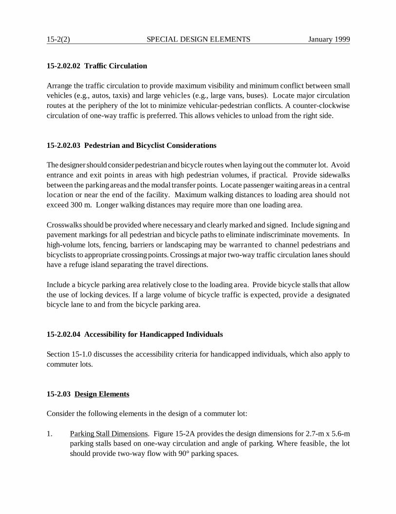
15-2(2) SPECIAL DESIGN ELEMENTS January 1999
15-2.02.02 Traffic Circulation
Arrange the traffic circulation to provide maximum visibility and minimum conflict between smallvehicles (e.g., autos, taxis) and large vehicles (e.g., large vans, buses). Locate major circulationroutes at the periphery of the lot to minimize vehicular-pedestrian conflicts. A counter-clockwisecirculation of one-way traffic is preferred. This allows vehicles to unload from the right side.
15-2.02.03 Pedestrian and Bicyclist Considerations
The designer should consider pedestrian and bicycle routes when laying out the commuter lot. Avoidentrance and exit points in areas with high pedestrian volumes, if practical. Provide sidewalksbetween the parking areas and the modal transfer points. Locate passenger waiting areas in a centrallocation or near the end of the facility. Maximum walking distances to loading area should notexceed 300 m. Longer walking distances may require more than one loading area.
Crosswalks should be provided where necessary and clearly marked and signed. Include signing andpavement markings for all pedestrian and bicycle paths to eliminate indiscriminate movements. Inhigh-volume lots, fencing, barriers or landscaping may be warranted to channel pedestrians andbicyclists to appropriate crossing points. Crossings at major two-way traffic circulation lanes shouldhave a refuge island separating the travel directions.
Include a bicycle parking area relatively close to the loading area. Provide bicycle stalls that allowthe use of locking devices. If a large volume of bicycle traffic is expected, provide a designatedbicycle lane to and from the bicycle parking area.
15-2.02.04 Accessibility for Handicapped Individuals
Section 15-1.0 discusses the accessibility criteria for handicapped individuals, which also apply tocommuter lots.
15-2.03 Design Elements
Consider the following elements in the design of a commuter lot:
1. Parking Stall Dimensions. Figure 15-2A provides the design dimensions for 2.7-m x 5.6-mparking stalls based on one-way circulation and angle of parking. Where feasible, the lotshould provide two-way flow with 90° parking spaces.
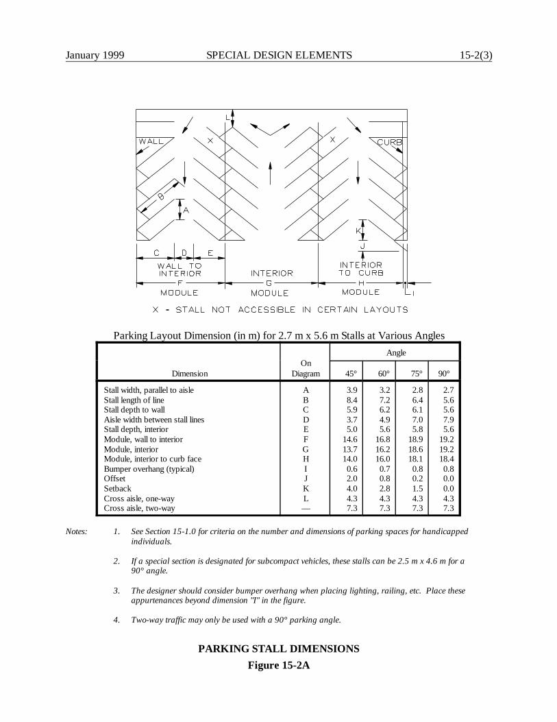
January 1999 SPECIAL DESIGN ELEMENTS 15-2(3)
Parking Layout Dimension (in m) for 2.7 m x 5.6 m Stalls at Various Angles
DimensionOn
Diagram
Angle
45° 60° 75° 90°
Stall width, parallel to aisleStall length of lineStall depth to wallAisle width between stall linesStall depth, interiorModule, wall to interiorModule, interiorModule, interior to curb faceBumper overhang (typical)OffsetSetbackCross aisle, one-wayCross aisle, two-way
ABCDEFGHIJKL—
3.98.45.93.75.0
14.613.714.00.62.04.04.37.3
3.27.26.24.95.6
16.816.216.00.70.82.84.37.3
2.8 6.4 6.1 7.05.8
18.918.618.10.80.21.54.37.3
2.75.65.67.95.6
19.219.218.40.80.00.04.37.3
Notes: 1. See Section 15-1.0 for criteria on the number and dimensions of parking spaces for handicappedindividuals.
2. If a special section is designated for subcompact vehicles, these stalls can be 2.5 m x 4.6 m for a90° angle.
3. The designer should consider bumper overhang when placing lighting, railing, etc. Place theseappurtenances beyond dimension "I" in the figure.
4. Two-way traffic may only be used with a 90° parking angle.
PARKING STALL DIMENSIONSFigure 15-2A

15-2(4) SPECIAL DESIGN ELEMENTS January 1999
2. Bus Loading Areas. Design the bus loading and unloading areas to provide for continuouscounter-clockwise circulation and for curb parking without backing maneuvers. The trafficlanes and the curb loading area should each be 3.6-m wide. Figure 15-2B provides criteriafor the recommended lengths of bus-loading areas. Section 15-3.0 discusses bus stops alongstreets and other access facilities.
3. Sidewalk Dimensions. All sidewalks should be paved and be at least 1.5-m wide. In loadingareas, the width should be at least 3.6-m. Provide a 150-mm raised platform in the loadingarea to assist in the loading. Curb-cut ramps are required for access to sidewalks and loadingareas, see Section 15-1.0.
4. Cross Slope. To provide proper drainage, the minimum gradient on the commuter lot shouldbe 1%. As a maximum, the gradient should not exceed 5%. If available, design the lot todirect the drainage runoff into existing drainage systems. If water impoundment cannot beavoided along pedestrian routes, bicycle routes and standing areas, provide drop inlets andunderground drainage. In parking areas, design the drainage to avoid standing water. Thedetailed drainage design for the lot should be prepared using the Department's DrainageManual to determine design frequency, pavement discharge and capacity of drainage inlets.
5. Pavement Design. A typical pavement design for a commuter lot is 50 mm to 75 mm ofbituminous concrete on 250 mm of subbase. Where curbs are used within the lot, they willnormally be the bituminous concrete lip curbing (BCLC) type.
6. Shelters. Where a loading area for buses or trains will be provided, include a shelter in thedesign. The shelter should provide approximately 0.5 m2 of covered area per person. At aminimum, the shelter should provide lighting, benches and trash receptacles. Other amenitiesmay include routing information signs and a telephone. For handicapped accessibilityrequirements, see Section 15-1.0.
7. Lighting. Light the commuter lot for pedestrian safety and lot security. Ensure provisionsare considered for location of lighting supports and power lines. Coordinate the lightingdesign with the Division of Traffic Engineering. All interior light standards should beprotected from bumper damage.
8. Traffic Control Devices. Provide signs and pavement markings to direct drivers andpedestrians to appropriate loading zones, parking areas, bicycle facilities, handicappedparking and entrances and exits. Coordinate the use of traffic control devices with theDivision of Traffic Engineering.
9. Fencing. Provide fencing around the entire lot according to field conditions.
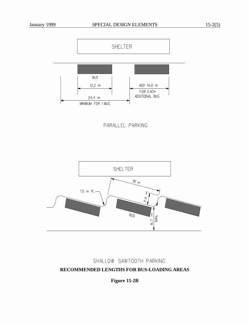
January 1999 SPECIAL DESIGN ELEMENTS 15-2(5)
RECOMMENDED LENGTHS FOR BUS-LOADING AREAS
Figure 15-2B
15-2(6) SPECIAL DESIGN ELEMENTS January 1999
10. Landscaping. In some locations, consider landscaping to minimize the visual impact of thecommuter lot. This may include providing a buffer zone around the perimeter of the lot orimproving the aesthetics of the lot itself. Desirably, include a 3.0 m - 6.0 m buffer zonearound the lot to accommodate vegetation screens. Also, traffic islands and parking lotseparators provide suitable locations for shrubs and trees. Section 15-5.0 discussesDepartment policies on landscaping. Specifically for commuter lots, landscaping shouldinclude low maintenance vegetation and vegetation which does not cause visibility problems.
11. Maintenance Considerations. To minimize maintenance, the design should include a 3.0-mto 6.0-m snow shelf around the perimeter of the lot, at least on two sides, to provide storagespace for snow removal. This area can coincide with the buffer zone around the lot, providedthat the entire area is not filled with shrubs or trees. Place any fencing outside the snow shelf.Also, keep raised traffic islands to a minimum; painted islands are preferred.
January 1999 SPECIAL DESIGN ELEMENTS 15-3(1)
15-3.0 BUS STOPS AND TURNOUTS
15-3.01 Location
15-3.01.01 Bus Stops
If local bus routes are located on an urban or suburban highway, the designer should consider theirimpact on normal traffic operations. The stop-and-go pattern of local buses will disrupt traffic flow,but certain measures can minimize the disruption. The location of bus stops is particularly important.These are determined not only by convenience to patrons, but also by the design and operationalcharacteristics of the highway and the roadside environment. If the bus must make a left-turn, forexample, do not locate a bus stop in the block preceding the left turn.
Some considerations in selecting an appropriate bus-stop location are listed below:
1. Far-Side Stops. The far side of at-grade intersections is generally superior to near-side ormid-block bus stops. Far-side stops produce less impediment to through traffic and right-turning traffic; they do not interfere as much with corner sight distance; and they lendthemselves better to bus turnouts.
2. Near-Side Stops. Near-side stops allow easier vehicle re-entry into the traffic stream wherecurb parking is allowed, and they can increase street capacity. At intersections where thereis a high volume of right-turning vehicles, near-side stops can result in traffic conflicts andshould be avoided. However, near-side stops must be used where the bus will make a rightturn at the intersection.
3. Mid-Block Stops. Mid-block bus stops may be advantageous where the distance betweenintersections is large or where there is a fairly heavy and continuous transit demandthroughout the block. They may be appropriate if a large traffic generator is located in mid-block. Mid-block bus stops may also be considered where right turns at an intersection arehigh (250 in peak hour) and far-side stops are not practical.
15-3.01.02 Bus Turnouts
Interference between buses and other traffic can be reduced significantly by providing bus turnouts.Turnouts remove stopped buses from the through lanes and provide a well-defined user area for busstops. Consider turnouts under the following conditions:
1. The street provides arterial service with high traffic speeds and volumes and high-volume buspatronage.
15-3(2) SPECIAL DESIGN ELEMENTS January 1999
2. Right-of-way width is sufficient to prevent adverse impact on sidewalk pedestrianmovements.
3. Curb parking is prohibited, at least during peak hours.
4. During peak-hour traffic, there are at least 500 vehicles per hour in the curb lane.
5. Bus volumes do not justify an exclusive bus lane, but there are at least 100 buses per day andat least 10 to 15 buses during the peak hour.
6. The average bus dwell time generally exceeds 10 seconds per stop.
7. At locations where specially equipped buses are used to load and unload handicappedindividuals.
15-3.02 Design
15-3.02.01 Bus Stops
Figure 15-3A provides the recommended distances for the prohibition of on-street parking near busstops. Where articulated buses are expected to use these stops, add an additional 6 m to thesedistances. Provide an additional 14 m of length for each additional bus expected to stopsimultaneously at any given bus stop area. This allows for the length of the extra bus (12.2 m) plus1.8 m between buses.
15-3.02.02 Bus Turnouts
The following design criteria will apply:
1. The bus turnout should be 3.0 m to 3.6 m wide.
2. The full-width area of the turnout should be at least 15 m long. Where articulated buses areexpected, the turnout should be 21 m. For a two-bus turnout, add 14 m.
3. Figure 15-3B illustrates the design details for bus turnouts. In the transition areas, providean entering taper no sharper than 5:1 and a re-entry taper no sharper than 3:1. As analternative, short horizontal curves (30-m radius) may be used on the entry end and 15-m to
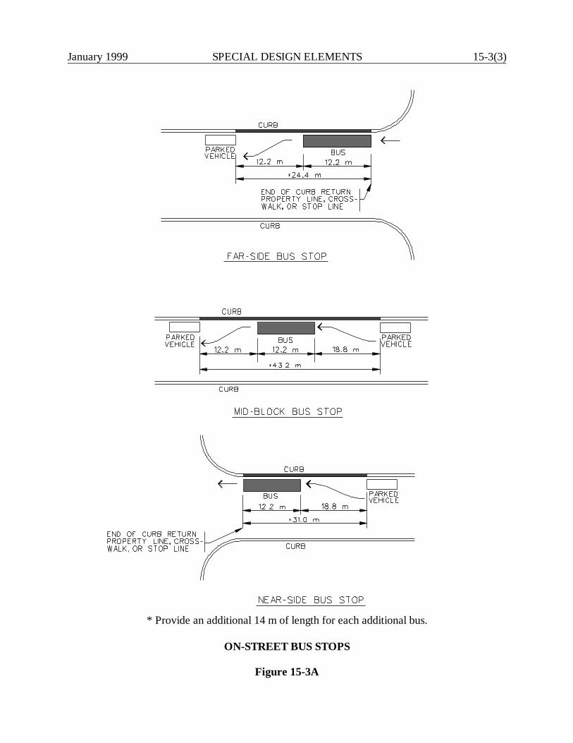
January 1999 SPECIAL DESIGN ELEMENTS 15-3(3)
* Provide an additional 14 m of length for each additional bus.
ON-STREET BUS STOPS
Figure 15-3A
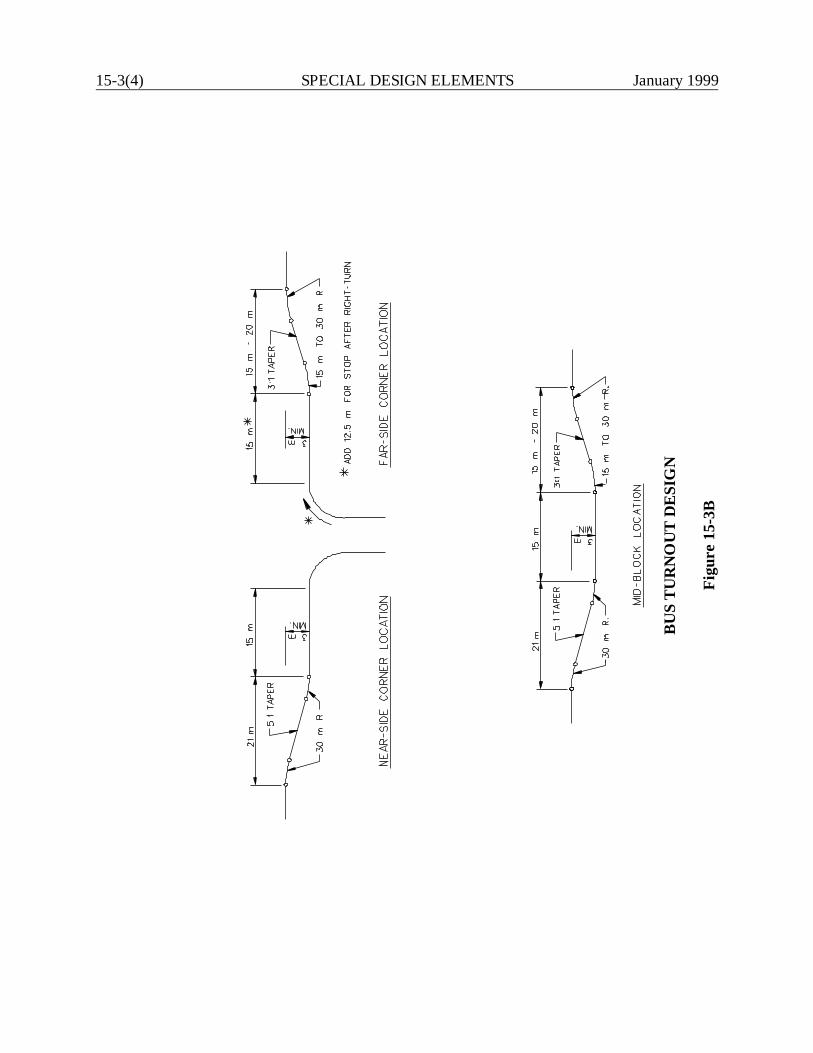
15-3(4) SPECIAL DESIGN ELEMENTS January 1999
BU
S T
UR
NO
UT
DE
SIG
N
Figu
re 1
5-3B
January 1999 SPECIAL DESIGN ELEMENTS 15-3(5)
30-m curves on the re-entry end. Where a turnout is located at a far-side or near-sidelocation, the cross street area can be assumed to fulfill the need for the exit or entry area,whichever applies.
15-3.02.03 Bus Stop Pads
All new bus stops which are constructed for use with lifts or ramps must meet the handicappedaccessibility criteria set forth in Section 15-1.0.
15-3.02.04 Bus Shelters
Provide shelters at all major bus stops (more than 100 boarding or transferring passengers per day).Also, provide shelters at stops that primarily serve the elderly and handicapped individuals, such asretirement homes and hospitals. Benches are also desirable at these locations. The designer shouldconsider the following in the design of bus shelters:
1. Visibility. To enhance passenger safety, the shelter sides should provide the maximumtransparency as practical. In addition, do not place shelters such that it limits the generalpublic's view of the shelter interior.
2. Selection. Contact the local transit agency to determine if they use a standardized shelterdesign.
3. Appearance. Shelters should be pleasing and blend with their surroundings. Shelters shouldalso be clearly identified with "bus logo" symbols to discourage non-patron use.
4. Handicapped Accessibility. Design new bus shelters to meet the accessibility criteriapresented in Section 15-1.0.
5. Placement. Do not place shelters where they will restrict vehicular sight distance, pedestrianflow or handicapped accessibility. It should also be placed so that waste and debris are notallowed to accumulate around the shelter.
6. Responsibility. The local transit agency is responsible for providing and maintaining theshelter.
7. Capacity. The maximum shelter size is based upon the maximum expected passengeraccumulation at a bus stop between bus runs. This determination should be coordinated withthe Bureau of Public Transportation. The designer can assume approximately 0.5 m2 per

15-3(6) SPECIAL DESIGN ELEMENTS January 1999
person to determine the appropriate shelter size. See Section 15-1.0 for minimumhandicapped accessibility requirements.
January 1999 SPECIAL DESIGN ELEMENTS 15-4(1)
15-4.0 BIKEWAYS
The majority of bicycling will take place on public roads with no dedicated space for bicyclists.Bicyclists can be expected to ride on almost all roadways. Sometimes they use sidewalks as jointbicycle and pedestrian facilities, unless such usage is prohibited by local ordinance. This sectionprimarily provides information on the development of new facilities to enhance and encourage safebicycle travel.
15-4.01 Bikeway Classifications
The Department has adopted the nomenclature used by AASHTO for bikeway classifications. Thefollowing definitions will apply:
1. Bikeway. Any road, path or way which in some manner is specifically designated as beingopen to bicycle travel, regardless of whether such facilities are designated for the exclusiveuse of bicycles or are to be shared with other transportation modes.
2. Shared Roadway. Any roadway upon which a bicycle lane is not designated and which maybe legally used by bicycles regardless of whether such facility is specifically designated asa bikeway.
3. Bicycle Path. A bikeway physically separated from motorized vehicular traffic by an openspace or barrier and either within the highway right-of-way or within an independent right-of-way. Bicycle paths may assume different forms, as conditions warrant. They may be two-direction, multilane facilities or, where the path would parallel a roadway with limited right-of-way, a single lane on both sides of the road.
4. Bicycle Lane. A portion of a roadway which has been designated by striping, signing andpavement markings for the preferential or exclusive use of bicyclists. It is distinguished fromthe traveled way portion of the roadway by a physical or symbolic barrier. Bicycle lanes mayalso assume varying forms but may generally be included in one of the following categories:
a. bicycle lane between parking lane and traveled way; orb. bicycle lane between roadway edge and traveled way, where parking is prohibited.
15-4.02 WarrantsEach type of facility has its own merits and disadvantages. Care must be exercised in choosing theappropriate type of facility for a given situation. Each route is unique and must be judged on its
15-4(2) SPECIAL DESIGN ELEMENTS January 1999
individual conditions. The Connecticut Statewide Bicycle and Pedestrian Transportation Plan andAASHTO Guide for the Development of Bicycle Facilities provides additional guidance on theselection of bikeways.
15-4.03 Bikeway Design Elements
For design details of bicycle facilities, the designer is referred to the Connecticut Statewide Bicycleand Pedestrian Transportation Plan and the AASHTO Guide for the Development of BicycleFacilities.
January 1999 SPECIAL DESIGN ELEMENTS 15-5(1)
15-5.0 LANDSCAPING
Roadside landscaping can greatly enhance the aesthetic value of a highway. Consider landscapingtreatments early in the project development so that they can be easily and inexpensivelyincorporated into the project design. Landscaping will be considered on a project-by-projectassessment. The designer should also reference the AASHTO A Guide for Transportation Landscapeand Environmental Design for more information on landscaping. The Department's landscaping staffwithin the Office of Engineering will determine the proper landscaping treatment for each project.
15-5.01 General Benefits
Roadside landscaping can be designed advantageously to yield several benefits. The most importantobjective is to fit the highway naturally into the existing terrain. Retain the existing landscape to themaximum extent practical. Following is a brief discussion of the benefits of proper landscaping:
1. Aesthetics. Gentle slopes, mountains, parks, bodies of water, and vegetation have an obviousaesthetic appeal to the highway user. Landscaping techniques can be used effectively toenhance the view from the highway. The designer should reference the FHWA publicationVisual Impact Assessment for Highway Projects for more information.
In rural areas, the landscaping should be natural and eliminate construction scars. Theplanting shape and spacing should be irregular to avoid a cosmetic appearance.
In urban areas, the smaller details of the landscape predominate and plantings become moreformal. The interaction between the occupants of slow-moving vehicles and pedestrians withthe landscape determines the scale of the aesthetic details. In some cases, the designer maybe able to provide walking areas, small parks, etc. Landscaping should be pleasant, neat,sometimes ornamental, and require low maintenance.
2. Erosion. Landscaping and erosion control are interrelated. Flat and rounded slopes andvegetation serve to both prevent erosion and provide aesthetic value.
3. Screening. Landscaping can be used to effectively screen headlight glare and unsightlyroadside views. It also can be used as a buffer for existing residences.
4. Maintenance. Landscaping decisions will greatly affect roadside maintenance. Maintenanceactivities for mowing, fertilizing, and using herbicides should be considered when designingthe roadside landscape.
5. Safety. The effects on roadside safety should be reflected in the landscape treatment (seeChapter Thirteen). Flat, rounded slopes are both safer and more aesthetic. Unless protected

15-5(2) SPECIAL DESIGN ELEMENTS January 1999
by guide rail, plant major trees outside of the clear zone, see Section 13-2.0. Shrubs andminor trees may be planted closer to the traveled way where traffic delineation will berequired. Landscaping should not be placed in ramp gore areas, near intersections orturnouts that would restrict sight distances.
15-5.02 Landscaping Policies
15-5.02.01 Planting Policy
All projects which include planting must have a special provision which requires the contractor tobe responsible for a plant establishment period of one growing season. The time begins after all plantmaterials in the contract have been planted.
15-5.02.02 Protection of Existing Vegetation
The Department's general policy is that, wherever practical, trees and other landscaping features willnot be removed on highway projects. This objective, however, must be compatible with otherconsiderations such as roadside safety, geometric design, utilities, terrain, public acceptance andeconomics. The Department has placed a special emphasis on saving valuable shade trees wheneverpractical. The plans should clearly designate all shade trees which will be saved.
15-5.02.03 Turf Establishment, Topsoil and Sodding
In areas disturbed by construction work, the designer must ensure that the turf is reestablished. Turfestablishment refers to the reseeding of disturbed areas. The designer should use the guidance in thefollowing comments to determine the appropriate turf establishment, depending upon individual siteconditions. In addition, the turf placement must reflect the requirements of the Department'sStandard Specifications for Roads, Bridges and Incidental Construction.
1. Topsoil. Place topsoil to a depth of 150 mm at all designated locations. The following topsoilrequirements apply to the indicated location:
a. Freeways. Place topsoil on all fill slopes 1:5 and flatter to a width not to exceed 6.0m from the edge of shoulder. Where abutting properties are subject to intensive
January 1999 SPECIAL DESIGN ELEMENTS 15-5(3)
mowing or in other special cases, include topsoil for all areas disturbed by construc-tion.
b. All other Highways. Topsoil should normally not be required at locations involvingabutting undeveloped properties. In areas where sodding is required, include topsoilin accordance with the Department's specifications.
c. Medians. In general, median areas should be topsoiled to a width not to exceed 6.0m from the edge of shoulders on both sides. Where the width remaining is 6.0 m orless, include topsoil for the entire median.
d. Gore Areas. Place topsoil from the end of the gore area pavement (3.0 m width) atthe bifurcation for a distance not to exceed 22.5 m parallel to the highway for the fullwidth between the roadways.
e. Bridge Abutments. For structures crossing roadways, place topsoil on the approachslopes for a distance not to exceed 15 m. This coverage is to extend from the top ofslope to the toe of slope.
f. Other Locations. Place topsoil at any other special locations, especially ininterchange areas as designated by qualified personnel.
2. Planting of Grass. Lime, seed, fertilize and mulch all areas disturbed by construction, exceptexposed rock surfaces and areas to be sodded, regardless of the presence or absence oftopsoil. Estimate the amount of fertilizing, seeding, mulching, and liming for such areas.Estimate liming at the rate of 2200 kg per hectare.
3. Sodding. Where developed properties and/or areas of intensive mowing abut the highwayproject (e.g., lawns of residences, hospitals, public parks), sod all adjacent areas disturbedby construction in accordance with the Department's specifications.
In addition to the above guidance for turf establishment, the designer must ensure that the projectplans and quantity estimates adhere to certain criteria. The designer will determine the type of turfestablishment and the areas within the construction limits which will be treated. These must bedesignated on the project plans. On this basis, the Office of Engineering, either by its own forces orwith consulting engineers, will compute the quantities and prepare the necessary plans, specialprovisions and estimates for inclusion in the construction plans. In addition, the following will apply:
1. Project Plans. The requirements of turf establishment should be indicated on the plansaccording to the size of the project. On minor projects, these requirements generally shouldbe reported on the detailed estimate sheet by stations. On larger projects which require Index
15-5(4) SPECIAL DESIGN ELEMENTS January 1999
Plans, indicate the turf establishment on these sheets where such information will notseriously conflict with the data normally reported thereon. Otherwise, prepare supplementalIndex Plan sheets showing turfing requirements and include them in the contract drawings.
2. Quantity Estimates. Before preparing quantity estimates, the designer should schedule areview of the proposed turf establishment requirements with the qualified personnel in theOffice of Engineering. When estimating quantities of work for turf establishment, add 3.0 mto the measured length of slope to minimize the possibility of overruns. Do not indicate thisadditional slope length on the plans. When estimating topsoil and sodding quantities, use themeasured length of the cross section and not the projected length from the plan sheets.
January 1999 SPECIAL DESIGN ELEMENTS 15-6(1)
15-6.0 FENCING
Fencing should be provided along high-speed highways to protect the driver from unexpected intrusionsfrom outside of the right-of-way line. Fencing prevents unauthorized and unsafe entry to the highway byvehicles, pedestrians or animals. It also prevents objects from being dropped or thrown from highwayoverpasses.
Except where warranted for highway reasons, fencing is normally the responsibility of the abutting propertyowner. They may be necessary for retaining livestock, discouraging trespassing, defining propertyboundaries, or otherwise to keep land use activities within bounds. If private fences are impacted by ahighway project, their relocation or disposition is usually reconciled as part of the property agreement.
15-6.01 General Warrants and Location
In general, the following will apply:
1. Warrants. Fencing is warranted to:
a. keep animals off the highway;
b. keep children or pedestrians off the highway;
c. protect children and pedestrians from a precipitous slope or drop off;
d. prevent vehicles and people from entering or leaving the highway at unauthorized places;and
e. prevent stones or other objects from being dropped or thrown from highway overpassesonto vehicles passing underneath.
2. Location. Fencing is typically provided along access-controlled facilities; near schools, playgroundsand parks; near livestock areas; on some bridges; and between frontage roads and the highwaymainline. Fencing is usually erected parallel to the highway centerline. Where taking lines are irregu-lar, the fencing should still be basically parallel to the highway, provided the fencing is within thehighway right-of-way. The fence line should be reasonably close to the right-of-way line; however,deviations are acceptable where existing obstructions (e.g., hedges) would have to be destroyed.
15-6(2) SPECIAL DESIGN ELEMENTS January 1999
Occasionally, the fence line will intersect a stream. The fencing may cross the stream withoutdeviation, or it may be angled in and terminated at the bridge abutment or culvert wing wall. Thetreatment will vary according to the size of the stream.
15-6.02 Freeways
The following will apply to fencing along freeways:
1. Warrants. Provide continuous fencing on either the right-of-way or access-control line. However,engineering judgment should dictate exceptions. In addition, where a noise barrier exists, fencingmay not be required to effectively preserve access control.
2. Location. Construct controlled-access fencing on State right-of-way with the face of the fencingtoward the abutting property. It will be maintained by the State, delineated on contract plans anddetermined in the overall development of the design.
3. Type. The following will apply:
a. Chain link fence is generally used on freeways, see the Connecticut Standard Sheets.Use 1.8-m high chain link fence in areas having a high concentration of children such asschools, churches and playgrounds. Use 1.5-m high chain link fence in areas adjacent tohousing developments, single-family homes, parks, reservoirs, commercial and industrialproperties, etc. During design and construction, the designer must consider impendingdevelopment of this type adjacent to the highway, and chain link fence of the appropriateheight may be installed to preclude replacement a short time later. In rural areas where littledevelopment is planned, wire fencing on steel posts may be used.
b. Normally, a coil spring tension wire is used at the top of a chain link fence. However, inareas where the fence will be subject to abuse and where there is little likelihood that it willbe struck by a vehicle, a top rail may be used to provide rigidity to the installation.
c. Provide gates with locks, where required, to allow access by maintenance forces.
4. Payments. Fencing payments (for fencing along the right-of-way boundary) will not be made inright-of-way settlements. The Office of Rights of Way will note on property agreements that fencingwill be installed by the State wherever delineated on the plans.
January 1999 SPECIAL DESIGN ELEMENTS 15-6(3)
15-6.03 Unlimited Access Highways
The following will apply to fencing along unlimited access highways:
1. Location. Posts will be on the land of the abutting owner, and the face of the fencing is usually onthe highway line. If by agreement with the property owner, the face of the fence may be on theother side of post. For stone walls, the face will be on the highway line, and the wall on the landof the abutting owner. The abutting owner is responsible for maintenance of all fences on unlimitedaccess highways. The designer will include an unassigned length in the contract estimate.
2. Type. Fencing may be:
a. wire fencing on wood posts (steel posts as required for ledge);b. stone wall or farm wall fencing; orc. chain link fence.
Fencing locations and types will be determined by agreement between the property owner and Department.
15-6.04 Fencing and Railings on Highway Structures
15-6.04.01 General
A railing is required on all parapets less than 1075 mm in height. The railing will be either a pedestrianrailing, bicycle railing or protective fence. In addition to the following sections, Section 12 of the BridgeDesign Manual contains additional information on railing and fencing of highway overpasses.
Protective fencing should satisfy the aesthetic consideration of the structure and should be designed inconformance with the latest Department criteria for fencing. From a maintenance perspective, vinyl-coatedchain-link fabric should be used on most bridges. Anodized aluminum fences should only be used withwritten approval. If protective fencing is provided, pedestrian and bicycle railings do not need to beprovided.

15-6(4) SPECIAL DESIGN ELEMENTS January 1999
MARCH 2000
15-6.04.02 Highway Overpasses with Sidewalks
The following will apply for highway overpasses with one or more sidewalks:
1. Protective Fencing. Protective fencing is required on both parapets. The height of the fencingabove the top of the parapet will be a minimum of 1525 mm. The maximum size opening in thefence will be determined by the designer and will be approved by the Department. Also, thedesigner should investigate the need for a curved top fence.
2. Pedestrian Railing. A pedestrian railing is not required.
3. Bicycle Railing. A bicycle railing is not required.
15-6.04.03 Highway Overpasses without Sidewalks
The following will apply for highway overpasses without sidewalks:
1. Protective Fencing. Protective fencing is required on highway overpasses without sidewalks, whichcarry local or secondary roads over a limited access highway.
2. Pedestrian Railing. A pedestrian railing is required on both parapets for parapets less than 1075mm high, unless protective fencing is provided.
3. Bicycle Railing. A bicycle railing is required on designated bicycle routes, unless protective fencingis provided.
15-6.04.04 Stream and Wetland Overpasses
The following apply to stream and wetland overpasses with or without sidewalks:
1. Protective Fencing. In general, fencing is not required on highway overpasses without sidewalks,except where unusual conditions are present which affect public safety below.
2. Pedestrian Railing. A pedestrian railing is required on both parapets for parapets less than 1075mm high.
3. Bicycle Railing. A bicycle railing is required on designated bicycle routes.
January 1999 SPECIAL DESIGN ELEMENTS 15-6(5)
15-6.04.05 Railroad Overpasses
The following will apply to all railroad overpasses:
1. Protective Fencing. Protective fencing is generally required on both parapets on the span over therailroad tracks. On long structures, protective fencing is required over the tracks plus a minimumof 7600 mm beyond the outside of track, measured perpendicular to the track.
The following criteria pertain to the height of the protective fence above the top of the parapet andthe maximum size of opening:
LocationHeight(mm)
Maximum Size Opening
Non-Electrified Zone 1525 (min.) 13 mm or as approved by the Department
Electrified Zone 1525 (min.)* Solid Barrier Required
* Use a 2135-mm high protective fence with a curved top at all sidewalks.
2. Pedestrian Railing. A pedestrian railing is not required where a protective fence is provided.However on long structures, provide pedestrian railing on both parapets outside the limits forprotective fencing as defined in Comment #1.
3. Bicycle Railing. A bicycle railing is not required where a protective fence is provided. Howeveron long structures, provide bicycle railing outside the limits for protective fencing as defined inComment #1 on designated bicycle routes.
15-6.04.06 Pedestrian Overpasses
Provide complete enclosures for pedestrian structures crossing over highways and railroads. The need forprotective fencing on pedestrian structures at streams or woodland crossings will be determined on a case-by-case basis.
15-6.04.07 Walls
The following will apply to fencing and railing on structures other than overpasses:
1. U-Type Wingwalls. The warrants for pedestrian railing, bicycle railing or protective fencing on U-type wingwalls are the same as for overpasses.
15-6(6) SPECIAL DESIGN ELEMENTS January 1999
2. Retaining Walls Adjacent to Traffic. A pedestrian railing is generally required for retaining wallswith parapets less than 1075 mm high and adjacent to traffic. Retaining walls along a sidewalkgenerally will follow the requirements of Section 15-6.04.02.
3. Retaining Walls not Adjacent to Traffic. A pedestrian railing or protective fencing is generallyrequired for walls that are not adjacent to traffic or for a sidewalk where the vertical drop off isgreater than 1500 mm.
4. Concrete Barrier Walls. Pedestrian railing, bicycle railing and protective fencing are generally notrequired on concrete barrier walls.
15-6.04.08 Railing and Fencing at Lighting and Signing Standards
Where lighting and signing standards are located on structures, the railing or fencing will be continuous atthese locations. Locate the lighting and signing standards outside of the continuous railing or fence. Designthe protective fencing with removable panels or other means to provide access to the handhole locations.Where practical, do not locate lighting and signing standards on a span over a railroad electrified zone.
15-6.05 Fencing Delineation on Contract Plans
Delineate all fencing requirements on contract plans. Show station references where needed for clarity.Where a fence is erected or replaced between a State highway and agricultural property, payment will beaccording to the provisions of the Connecticut General Statutes, Section 47-46 of Title 47, Chapter 823.

January 1999 SPECIAL DESIGN ELEMENTS 15-6(7)

January 1999 SPECIAL DESIGN ELEMENTS 15-7(1)
15-7.0 NOISE BARRIER IMPACTS
Noise barriers are erected to reduce the environmental impact on areas adjacent to a highway. They aredesigned to reduce the noise level of traffic adjacent to existing buildings to an acceptable level asdetermined by Federal guidelines. The Office of Planning is responsible for selection, location and designas related to the environment. However, the Office of Engineering must evaluate the impacts of the noisebarrier on the highway design. This section discusses those impacts.
15-7.01 Roadside Safety
Section 13-2.0 provides the Department's design criteria for clear zones. If practical, noise barrier wallsshould be placed outside of the applicable clear zone value. Otherwise, guide rail should be considered toshield the wall from run-off-the-road vehicles. The designer must ensure that adequate deflection distanceis available between the guide rail and noise barrier. Chapter Thirteen discusses the design of guide rail indetail.
If the noise barrier is a mound of dirt, the toe of the barrier should be traversable by a run-off-the-roadvehicle.
15-7.02 Sight Distance
For at-grade intersections, noise barriers should not be located in the triangle required for corner sightdistance. Section 11-2.0 provides the criteria to determine the required sight distance triangle.
Noise barriers can also impact sight distance along horizontal curves. Section 8-2.04 provides the detailedcriteria to determine the middle ordinate value which will yield the necessary sight distance. The locationof the noise barrier must be outside of this value.
15-7.03 Right-of-Way
The noise barrier must be located within the highway right-of-way.
15-7.04 Interference with Roadside Appurtenances
A noise barrier may be constructed on a new or on an existing highway. Its proposed location couldinterfere with proposed or existing roadside features, including signs, sign supports, utilities and
15-7(2) SPECIAL DESIGN ELEMENTS January 1999
illumination facilities. The designer must determine if these features are impacted by the noise barrier andmust coordinate with the applicable Department units to resolve any conflicts.
15-7.05 Additional Design Criteria
In addition to the criteria in the previous sections, the designer should also consider the following:
1. Standard Drawings. The Connecticut Standard Drawings provide additional details on noisewalls used by the Department.
2. Plans. All approved noise wall options will be included in the plans, unless there is a specific noisedesign criteria which would suggest one design over another.
3. Bridges. Bridge designs will not include masonry walls, or other walls with similar weight orattachment problems, which would result in additional structural loading problems.
4. Transitions. The Contractor will be responsible for any transition details which are necessary toproperly interface a structural noise wall with a ground mounted wall of a different type, subjectto the approval of the Engineer.
5. Earth Berms. Where field conditions and right-of-way permit, earth berms will be the primarydesign for noise barriers.
6. Wood Walls. The designer will design the structure mounted noise barrier walls, which will includeall of the wood noise barrier walls in the Connecticut Standard Drawings. For other than thewood noise barrier walls, the designer will invite the manufacturer to design the wall for eachstructure, unless the manufacturer has requested the Department not to have its wall included instructure designs.
7. Design Criteria. The designer will be responsible for obtaining the latest criteria for noise barrierwalls immediately before submitting the project for processing. This will ensure that all of the latestcriteria will be included. Where a structure is involved, the structural designer will obtain the latestcriteria for noise barrier walls immediately before designing the structure to ensure that the structureis designed to accommodate all of the suitable types of walls. The structural designer is alsoresponsible for all modifications to the design of the applicable standard walls which may berequired to ensure their suitability for use as a structure mounted noise barrier wall and for theconnection of the wall to the structure.
January 1999 SPECIAL DESIGN ELEMENTS 15-8(1)
15-8.0 REFERENCES
1. Accessibility Guidelines for Building and Facilities, U.S. Architectural and TransportationBarriers Compliance Board, 1991, 1994.
2. FHWA-IP-84-6, Guidelines for Making Pedestrian Crossing Structures Accessible, August,1984.
3. A Policy on Geometric Design of Highways and Streets, AASHTO, 1994.
4. Guide for the Design of Park-and-Ride Facilities, AASHTO, 1992.
5. Traffic Engineering Handbook, Institute of Transportation Engineers, 1992.
6. The Location and Design of Bus Transfer Facilities, Institute of Transportation Engineers, 1992.
7. Proper Location of Bus Stops, Institute of Transportation Engineers, 1986.
8. Guide for the Development of Bicycle Facilities, AASHTO, 1991.
9. Visual Impact Assessment for Highway Projects, FHWA, 1981.
10. A Guide for Transportation Landscape and Environmental Design, AASHTO, 1991.
11. An Informational Guide on Fencing Controlled Access Highways, AASHTO, 1967.

15-8(2) SPECIAL DESIGN ELEMENTS January 1999

January 1999 GLOSSARY GL-1
GLOSSARY
General
1. Access Control. The condition where the public authority fully or partially controls the rightof abutting owners to have access to and from the public highway.
2. Accessible Route. An accessible route is a continuous, unobstructed path connecting allaccessible elements and spaces in a building, facility or site. A “site” is defined as a parcel ofland bounded by a property line or a designated portion of a public right-of-way. A “facility”is defined as all or any portion of buildings, structures, site improvements, complexes,equipment, roads, walks, passageways, parking lots, or other real or personal property on asite.
3. Arterials. Highways which are characterized by a capacity to quickly move relatively largevolumes of traffic but often provide limited access to abutting properties. The arterial systemtypically provides for high travel speeds and the longest trip movements.
4. Average Running Speed. The distance summation for all vehicles over a specified section ofhighway divided by the running time summation for all vehicles.
5. Average Travel Speed. The distance summation for all vehicles divided by the total timesummation for all vehicles.
6. Bicycle Lane. A portion of a roadway which has been designated by striping, signing andpavement markings for the preferential or exclusive use of bicyclists.
7. Bicycle Path. A bikeway physically separated from motorized vehicular traffic by an openspace or barrier and either within the highway right-of-way or within an independent right-of-way.
8. Bikeway. Any road, path or way which in some manner is specifically designated as beingopen to bicycle travel, regardless of whether such facilities are designated for the exclusiveuse of bicycles or will be shared with other transportation modes.
9. Bridge. A structure, including supports, erected over a depression or obstruction, such aswater, a highway, or a railway, and having a track or passageway for carrying traffic or othermoving loads, and having an opening measured along the center of the roadway of more than6 m between undercopings of abutments or spring lines or arches or extreme ends of openings
GL-2 GLOSSARY January 1999
for multiple boxes; may include multiple pipes where the clear distance between openings isless than half of the smaller contiguous opening.
10. Bridge Roadway Width. The clear width of the structure measured at right angles to thecenter of the roadway between the bottom of curbs or, if curbs are not used, between theinner faces of parapet or railing.
11. Bridge to Remain in Place. An “existing bridge to remain in place” refers to any bridge workwhich does not require the total replacement of both the substructure and superstructure.
12. Built-up. An urban classification that refers to the central business district within anurbanized or small urban area. The roadside development has a high density and is oftencommercial. Access to property is the primary function of the road network in built-up areas;the average driver rarely passes through a built-up area for mobility purposes. Pedestrianconsiderations may be as important as vehicular considerations, especially at intersections.Right-of-way for roadway improvements is usually not available.
13. Bus. A heavy vehicle involved in the transport of passengers on a for-hire, charter orfranchised transit basis.
14. Collectors. Highways which are characterized by a roughly even distribution of their accessand mobility functions.
15. Control by Regulation. Where the public authority determines where private interests mayhave access to and from the public road system.
16. Controlling Design Criteria. A list of geometric criteria requiring FHWA or ConnDOTapproval if they are not met or exceeded.
17. Crosswalk. A marked lane for passage of pedestrians, bicycles, etc., traffic across a road orstreet.
18. Curb Cuts or Curb Ramps. The treatment at intersections for gradually lowering theelevation of sidewalks with curbs to the elevation of the street surface. The term “curbramps” is used in this Manual.
19. Department. Connecticut Department of Transportation.
20. Design Exception. The process of receiving approval from the FHWA or Department forusing design criteria which does not meet the criteria set forth in this Manual.
January 1999 GLOSSARY GL-3
21. Design Speed. Design speed is the maximum safe speed that can be maintained over aspecified section of highway when conditions are so favorable that the design features of thehighway govern.
22. Divided Highway. A highway with separated roadways for traffic moving in oppositedirections.
23. 85th-Percentile Speed. The speed below which 85 percent of vehicles travel on a givenhighway.
24. Expressways. Divide highway facilities which are characterized by full or partial control ofaccess.
25. Freeways. The highest level of arterial. These facilities are characterized by full control ofaccess, high design speeds, and a high level of driver comfort and safety.
26. Frontage Road. A road constructed adjacent and parallel to but separated from the highway
for service to abutting property and for control of access.
27. Full Control (Access Controlled). Full control of access is achieved by giving priority tothrough traffic by providing access only at grade separation interchanges with selected publicroads. No at-grade crossings or approaches are allowed. The freeway is the common termused for this type of highway. Full control of access maximizes the capacity, safety andvehicular speeds on the freeway.
28. Grade Separation. A crossing of two highways, or a highway and a railroad, at differentlevels.
29. High Speed. For geometric design purposes, high speed is defined as greater than 70 km/h.
30. Highway, Street or Road. A general term denoting a public way for purposes of vehiculartravel, including the entire area within the right of way. (Recommended usage: in urbanareas - highway or street, in rural areas - highway or road).
31. Intermediate. As urban classification that falls between suburban and built-up. Thesurrounding environment may be either residential, commercial or industrial or somecombination of these. On roads and streets in intermediate areas, the extent of roadsidedevelopment will have a significant impact on the selected speeds of drivers. Pedestrianactivity is a significant design consideration, and sidewalks and cross walks at intersectionsare common. The available right-of-way will often restrict the practical extent of roadwayimprovements.

GL-4 GLOSSARY January 1999
32. Interchange. A system of interconnecting roadways in conjunction with one or more gradeseparations, providing for the movement of traffic between two or more roadways ondifferent levels.
33. Intersection. The general area where two or more highways join or cross, within which areincluded the roadway and roadside facilities for traffic movements in that area.
34. Local Roads and Streets. All public roads and streets not classified as arterials or collectors.
35. Low-Moderate Density. A rural classification where the roadside development has increasedto a level where the prudent driver will instinctively reduce his/her speed as compared to anopen roadway. The driver must be more alert to the possibility of entering and exitingvehicles, but he/she is still able to maintain a relatively high travel speed. The estimatednumber of access points will average between 10 and 20 per kilometer per side. Right-of-waymay be difficult to attain.
36. Low Speed. For geometric design purposes, low speed is defined as 70 km/h or less.
37. Major Strategic Highway Network Connectors. Highways which provide access betweenmajor military installations and highways which are part of the Strategic Highway Network.
38. Moderate/High Density. A rural classification where the roadside development has increasedto a level which is comparable to a suburban area within an urbanized boundary. The extentof the development will have a significant impact on the selected travel speed of a prudentdriver. Exiting and entering vehicles are frequent, and traffic signals are typical at majorintersections. The estimated number of access points will average greater than 20 perkilometer per side. Right-of-way is usually quite difficult to attain.
39. National Highway System (NHS). A system of highways determined to have the greatestnational importance to transportation, commerce and defense in the United States. It consistsof the Interstate highway system, selected other principal arterials, and other facilities whichmeet the requirements of one of the subsystems within the NHS.
40. Noise Barrier. A structure designed to reduce the noise level of traffic adjacent to an existingbuilding to an acceptable level.
41. Open. A rural classification that fits the traditional concept of a rural area. The driver hasalmost total freedom of movement and is generally not affected by occasional access pointsalong the highway or road. For the purpose of determining the classification, access pointswill average less than 10 per kilometer per side. Right-of-way is usually not a problem.
January 1999 GLOSSARY GL-5
42. Operating Speed. The highest overall speed at which a driver can safely travel a givenhighway under favorable weather conditions and prevailing traffic conditions while at no timeexceeding the design speed.
43. Overpass. A grade separation where the subject highway passes over an intersecting highwayor railroad.
44. Partial Control. The authority to control access is exercised to give preference to throughtraffic to a degree that, in addition to access connections with selected frontage or local roads,there may be some crossing at grade and some private approach connections.
45. Posted Speed Limit. The recommended speed limit for a highway as determined byengineering and traffic investigations.
46. Ramp. A short roadway connecting two or more legs of an intersection or connecting afrontage road and main lane of a highway.
47. Recreational Vehicle. A heavy vehicle, generally operated by a private motorist, engaged inthe transportation of recreational equipment or facilities; examples include campers, boattrailers, motorcycle trailers, etc.
48. Right-of-Way (R/W). A general term denoting land, property, or interest therein, usually astrip acquired for or devoted to a highway use.
49. Roadway. (General) The portion of a highway including shoulders, for vehicular use. Adivided highway has two or more roadways. (Construction) The portion of a highway withinlimits of construction.
50. Running Speed. The average speed of a vehicle over a specified section of highway. It isequal to the distance traveled divided by the running time (the time the vehicle is in motion).
51. Rural Areas. Those places outside the boundaries of urban areas.
52. Shared Roadway. Any roadway upon which a bicycle lane is not designated and which maybe legally used by bicycles regardless of whether such facility is specifically designated as abikeway.
53. Signalized Intersection. An intersection where all legs are controlled by a traffic signal.

GL-6 GLOSSARY January 1999
54. State Highway System. The highway system under the jurisdiction of the ConnecticutDepartment of Transportation consisting of those inter-municipality and Interstate highways,including their extensions through incorporated areas.
55. Stopped Controlled Intersection. An intersection where one or more legs are controlled bya stop sign.
56. Strategic Highway Network. This is a network of highways which are important to theUnited States’ strategic defense policy and which provide defense access, continuity andemergency capabilities for defense purposes.
57. Suburban. An urban classification that is usually located at the fringes of urbanized and smallurban areas. The predominant character of the surrounding environment is usually residential,but it will also include a considerable number of commercial establishments. There may alsobe a few industrial parks in suburban areas. On suburban roads and streets, drivers usuallyhave a significant degree of freedom, but nonetheless, they must also devote some of theirattention to entering and exiting vehicles. Roadside development is characterized by low tomoderate density. Pedestrian activity may or may not be a significant design factor. Right-of-way is often available for roadway improvements.
58. Surface Transportation Program (STP). A block-grant program which provides Federal-aidfunds for any public road not functionally classified as a minor rural collector or a local roador street.
59. Truck. A heavy vehicle engaged primarily in the transport of goods and materials, or in thedelivery of services other than public transportation.
60. Underpass. A grade separation where the subject highway passes under an intersectinghighway or railroad.
61. Urban Areas. Those places within boundaries set by the responsible State and local officialshaving a population of 5000 or more.
Qualifying Words
1. Acceptable. Design criteria which do not meet values in the upper range, but yet isconsidered to be reasonable and safe for design purposes.
January 1999 GLOSSARY GL-7
2. Criteria. A term typically used to apply to design values, usually with no suggestion on thecriticality of the design value. Because of its basically neutral implication, this Manualfrequently uses “criteria” to refer to the design values presented.
3. Desirable, preferred. An indication that the designer should make every reasonable effort tomeet the criteria and should only use a “lesser” design after due consideration of the “better”design.
4. Guideline. Indicating a design value which establishes an approximate threshold which shouldbe met if considered practical.
5. Ideal. Indicating a standard of perfection (e.g., traffic capacity under “ideal” conditions).
6. Insignificant, minor. Indicating that the consequences from a given action are relatively smalland not an important factor in the decision-making for road design.
7. May, could, can, suggest, consider. A permissive condition. Designers are allowed to applyindividual judgment and discretion to the criteria when presented in this context. The decisionwill be based on a case-by-case assessment.
8. Minimum, maximum. Representative of generally accepted limits within the designcommunity, but not necessarily suggesting that these limits are inviolable. However, wherethe criteria presented in this context will not be met, the designer will in many cases needapproval.
9. Policy. Indicating ConnDOT practice which the Department generally expects the designerto follow, unless otherwise justified.
10. Possible. Indicating that which can be accomplished. Because of its rather restrictiveimplication, this word will not be used in this Manual for the application of design criteria.
11. Practical, feasible, cost-effective, reasonable. Advising the designer that the decision to applythe design criteria should be based on a subjective analysis of the anticipated benefits andcosts associated with the impacts of the decision. No formal analysis (e.g., cost-effectivenessanalysis) is intended, unless otherwise stated.
12. Shall, require, will, must. A mandatory condition. Designers are obligated to adhere to thecriteria and applications presented in this context or to perform the evaluation indicated. Forthe application of geometric design criteria, this Manual limits the use of these words.

GL-8 GLOSSARY January 1999
13. Should, recommend. An advisory condition. Designers are strongly encouraged to followthe criteria and guidance presented in this context, unless there is reasonable justification notto do so.
14. Significant, major. Indicating that the consequences from a given action are obvious to mostobservers and, in many cases, can be readily measured.
15. Standard. Indicating a design value which cannot be violated without severe consequences.This suggestion is generally inconsistent with geometric design criteria. Therefore, “standard”will not be used in this Manual to apply to geometric design criteria.
16. Trigger Value. The minimum geometric value at which the element should be considered forimprovement.
17. Typical. Indicating a design practice which is most often used in application and which islikely to be the “best” treatment at a given site.
18. Warranted, justified. Indicating that some well-accepted threshold or set of conditions hasbeen met. As used in this Manual, “warranted” or “justified” may apply to either objectiveor subjective evaluations. Note that, once the warranting threshold has been met, this is anindication that the design treatment should be considered and evaluated not that the designtreatment is automatically required.
Abbreviations
1. AASHTO. American Association of State Highway and Transportation Officials.
2. ADA. Americans with Disabilities Act.
3. CADD. Computer-Aided Drafting and Design.
4. CBD. Central Business Districts.
5. CGS. Connecticut General Statute.
6. CONNDOT. Connecticut Department of Transportation.
7. FHWA. Federal Highway Administration.
8. HBRRP. Highway Bridge Replacement/Rehabilitation Program.
January 1999 GLOSSARY GL-9
9. HCM. Highway Capacity Manual.
10. ITE. Institute of Transportation Engineers.
11. ISTEA. Intermodal Surface Transportation Efficiency Act of 1991.
12. MUTCD. Manual of Uniform Traffic Control Devices.
13. NCHRP. National Cooperative Highway Research Program.
14. NHS. National Highway System.
15. PS&E. Plans, Specifications and Estimates.
16. 3R. Resurfacing, restoration and rehabilitation.
17. 4R. Resurfacing, restoration, rehabilitation and reconstruction.
18. R/W. Right-of-way.
19. STC. State Traffic Commission.
20. STP. Surface Transportation Program.
21. TRB. Transportation Research Board.
22. TSM. Transportation Systems Management
23. USDOT. United States Department of Transportation.
Planning
1. Average Annual Daily Traffic (AADT). The total yearly volume in both directions of traveldivided by the number of days in a year.
2. Average Daily Traffic (ADT). The calculation of average traffic volumes in both directionsof travel in a time period greater than one day and less than one year and divided by thenumber of days in that time period.
GL-10 GLOSSARY January 1999
3. Capacity. The maximum number of vehicles which can reasonably be expected to traversea point or uniform section of a road during a given time period under prevailing roadway,traffic and control conditions.
4. Categorical Exclusion (CE). A classification for projects that will not induce significantenvironmental impacts or foreseeable alterations in land use, planned growth, developmentpatterns, traffic volumes, travel patterns, or natural or cultural resources.
5. Delay. The criteria performance measure on interrupted flow facilities, especially at signalizedintersections. For this element, average stopped-time delay is measured, which is expressedin seconds per vehicle.
6. Density. The number of vehicles occupying a given length of lane, averaged over time. It isusually expressed as vehicles per kilometer.
7. Design Hourly Volume (DHV). The 1-hour volume in both directions of travel in the designyear selected for determining the highway design.
8. Design Service Flow Rate. The maximum hourly vehicular volume which can pass througha highway element at the selected level of service.
9. Directional Design Hourly Volume (DDHV). The 1-hour volume in one direction of travelduring the DHV.
10. Directional Distribution (D). The division, by percent, of the traffic in each direction of travelduring the DHV, ADT or AADT.
11. Environmental Assessment (EA). A study to determine if the environmental impacts of aproject are significant, thus requiring the preparation of an EIS.
12. Environmental Impact Statement (EIS). A document which is prepared when it has beendetermined that a project will have a significant impact on the environment.
13. Equivalent Single-Axle Loads (ESAL's). The summation of equivalent 8165-kg single-axleloads used to combine mixed traffic to design traffic for the design period.
14. Finding of No Significant Impact (FONSI). A result of an EA that shows a project will notcause a significant impact to the environment.
15. Level of Service (LOS). A qualitative concept which has been developed to characterizeacceptable degrees of congestion as perceived by motorists.
January 1999 GLOSSARY GL-11
16. New Construction. Horizontal and vertical alignment construction, intersections at-grade,interchanges and bridges on new locations.
17. Peak-Hour Factor (PHF). A ratio of the total hourly volume to the maximum 15-minute rateof flow within the hour.
18. Peak-Rate of Flow. The highest equivalent hourly rate at which vehicles pass over a givenpoint or direction of a lane or roadway during a given time interval less than one-hour, usually15 minutes.
19. Project Scope of Work. The basic intent of the highway project which determines the overalllevel of highway improvement.
20. Reconstruction. Reconstruction of an existing highway mainline will typically include theaddition of travel lanes, reconstruction of the existing horizontal and vertical alignment, andreconstruction of intersections, interchanges and bridges.
21. 3R. Resurfacing, restoration and rehabilitation of an non-freeway facility which is mainly onan existing highway alignment.
22. 4R. Any work (resurfacing, restoration, rehabilitation and reconstruction) on an existingfreeway.
23. Spot Improvement. Improvements that are intended to correct an identified deficiency at anisolated location on non-freeways.
24. Traffic Composition. A factor which reflects the percentage of heavy vehicles (trucks, busesand recreational vehicles) in the traffic stream during the DHV.
Geometric
1. Acceleration Lanes. An auxiliary lane used by an entering vehicle to accelerate beforeentering the traveled way.
2. Auxiliary Lane. The portion of the roadway adjoining the through traveled way for purposessupplementary to through traffic movement including parking, speed change, turning, storagefor turning, weaving or truck climbing.
3. Axis of Rotation. The superelevation axis of rotation is the line about which the pavementis revolved to superelevate the roadway. This line will maintain the normal highway profile
GL-12 GLOSSARY January 1999
throughout the curve. The axis of rotation is generally located at the point of gradeapplication.
4. Back Slope. The side slope created by the connection of the ditch bottom, upward andoutward, to the natural ground.
5. Barrier Curb. A longitudinal element placed at the roadway edge for delineation, to controldrainage, to control access, etc. Barrier curbs may range in height between 150 mm and 300mm with a face steeper than 3 vertical to 1 horizontal.
6. Broken-Back Curves. Two closely spaced horizontal curves with deflections in the samedirection and a short intervening tangent.
7. Buffer Areas. The area or strip between the roadway and a sidewalk.
8. Channelization. The moving or directing of traffic through an intersection by the use ofpavement markings (including striping, raised reflectors, etc.) or raised islands.
9. Cloverleaf Interchange. An interchange with loop ramps in one or more quadrants. Fullcloverleaf interchanges have loop ramps in all quadrants.
10. Collector-Distributor Roads. A set of roadways at an interchange used to eliminate theweaving and reduce the number of exit and entrance points from the main through lanes ofa freeway.
11. Comfort Criteria. Criteria which is based on the comfort effect of change in vertical directionin a sag vertical curve because of the combined gravitational and centrifugal forces.
12. Compound Curves. These are a series of two or more simple curves with deflections in thesame direction immediately adjacent to each other.
13. Critical Length of Grade. The maximum length of a specific upgrade on which a loaded truckcan operate without an unreasonable reduction in speed.
14. Critical Parallel Slope. Slopes upon which a vehicle is likely to overturn. Under theDepartment’s roadside criteria, slopes steeper than 1:4 and 1:4 with curbing at the top arecritical.
15. Crossover Line. The lane line between any two adjacent lanes of traffic.
January 1999 GLOSSARY GL-13
16. Cross Slope. The slope in the cross section view of the travel lanes, expressed as a percentbased on the change in vertical compared to the change in horizontal.
17. Cross Slope Rollover. The algebraic difference between the slope of the through lane and theslope of the adjacent lane or shoulder within the traveled way or gore.
18. Cuts. Sections of highway located below natural ground elevation thereby requiringexcavation of earthen material.
19. Deceleration Lane. An auxiliary lane used by an exiting vehicle to reduce its speed.
20. Decision Sight Distance. Sight distance, which may be required in a complex environment,which is based on the driver’s reaction time.
21. Depressed Median. A median that is lower in elevation than the traveled way and so designedto carry a certain portion of the roadway water.
22. Design Vehicle. The vehicle used to determine turning radii, off-tracking characteristics,pavement designs, climbing lanes, etc.
23. Diamond Interchange. An interchange with one-way diagonal ramps in each quadrant andtwo at-grade intersections on the minor road.
24. Driveway. A road providing access from a public way to a highway, street, road, etc., orabutting property.
25. Fill Slopes. Slopes extending outward and downward from the hinge point to intersect thenatural ground line.
26. Flush Median. A median which is level with the surface of the adjacent roadway pavement.
27. Gore Area. The paved triangular area between the through lane and the exit lane, plus thegraded area beyond the gore nose.
28. Grade Separation. A crossing of two highways, or a highway and a railroad, at differentlevels.
29. Grade Slopes. The rate of slope between two adjacent VPI's expressed as a percent. Thenumerical value for percent of grade is the vertical rise or fall in meters for each 100 m ofhorizontal distance. Upgrades in the direction of stationing are identified as plus (+).Downgrades are identified as minus (-).
GL-14 GLOSSARY January 1999
30. Horizontal Sight Distance. The sight distance required across the inside of a horizontal curve.
31. Intersection Sight Distance (ISD). The sight distance required within the corners ofintersections to safely allow a variety of vehicular maneuvers based on the type of trafficcontrol at the intersection.
32. K-Values. The horizontal distance needed to produce a 1% change in gradient.
33. Landing Area. The area approaching an intersection for stopping and storage of vehicles.
34. Level Terrain. Level terrain is generally considered to be flat, which has minimal impact onvehicular performance. Highway sight distances are either long or could be made longwithout major construction expense.
35. Low-Speed Urban Streets. All streets within urbanized and small urban areas with a designspeed of 70 km/h or less.
36. Maximum Side Friction (fmax). Limiting values selected by AASHTO for use in the design ofhorizontal curves. The designated fmax values represent a threshold of driver discomfort andnot the point of impending skid.
37. Maximum Superelevation (emax). The overall superelevation control used on a specificfacility. Its selection depends on several factors including overall climatic conditions, terrainconditions, type of area (rural or urban) and highway functional classification.
38. Median. The portion of a divided highway separating the two traveled ways for traffic inopposite directions. The median width includes both inside shoulders.
39. Median Opening. An at-grade opening in the median to allow vehicles to cross from oneroadway to the next.
40. Mountable Curb. A longitudinal element placed at the roadway edge for delineation, tocontrol drainage, to control access, etc. Mountable curbs have a height of 150 mm or lesswith a face no steeper than 3 vertical to 1 horizontal.
41. Mountainous Terrain. Longitudinal and transverse changes in elevation are abrupt, andbenching and side hill excavation are frequently required to provide the highway alignment.Mountainous terrain aggravates the performance of trucks relative to passenger cars, resultingin some trucks operating at crawl speeds.
January 1999 GLOSSARY GL-15
42. Non-Recoverable Parallel Slope. Slopes which are steeper than 1:4. Most drivers will notbe able to recover and return to the highway. The Department has decided to treat this rangeof cross slopes as critical.
43. Normal Crown (NC). The typical cross section on a tangent section (i.e., no superelevation).
44. Open Roadways. All urban facilities with a design speed greater than 70 km/h and all ruralfacilities regardless of design speed.
45. Parking Lane. An auxiliary lane primarily for the parking of vehicles.
46. Partial Cloverleaf Interchange. An interchange with loop ramps in one, two or threequadrants.
47. PC. Point of curvature (beginning of curve).
48. PCC. Point of compound curvature.
49. Performance Curves. A set of curves which illustrate the effect grades will have on the designvehicle's acceleration and/or deceleration.
50. PI. Point of intersection of tangents.
51. Point of Grade Application. The point on the cross section where the elevation of thecalculated profile grade line is located.
52. PRC. Point of reverse curvature.
53. PT. Point of tangency (end of curve).
54. PVC. (Point of Vertical Curvature). The point at which a tangent grade ends and the verticalcurve begins.
55. PVI. (Point of Vertical Intersection). The point where the extension of two tangent gradesintersect.
56. PVT. (Point of Vertical Tangency). The point at which the vertical curve ends and thetangent grade begins.
57. Raised Median. A median which contains a raised portion within its limits.
GL-16 GLOSSARY January 1999
58. Recoverable Parallel Slope. Slopes which can be safely traversed and upon which an errantmotorist has a reasonable opportunity to stop and return to the roadway. The Departmentconsiders slopes flatter than 1:4 and slopes of 1:4 without curbing at their top recoverable.
59. Relative Longitudinal Slope. In superelevation transition sections on two-lane facilities, therelative gradient between the profile grade and edge of traveled way.
60. Reverse Adverse Crown (RC). A superelevated roadway section which is sloped across theentire traveled way in the same direction and at a rate equal to the cross slope on a tangentsection.
61. Reverse Curves. These are two simple curves with deflections in opposite directions whichare joined by a relatively short tangent distance.
62. Roadside. A general term denoting the area adjoining the outer edge of the roadway.Extensive areas between the roadways of a divided highway may also be considered roadside.
63. Roadway Section. The combination of the traveled way, both shoulders and any auxiliarylanes on the highway mainline.
64. Rolling Terrain. The natural slopes consistently rise above and fall below the roadway gradeand, occasionally, steep slopes present some restriction to the highway alignment. In general,rolling terrain generates steeper grades, causing trucks to reduce speeds below those ofpassenger cars.
65. Shoulder. The portion of the roadway contiguous to the traveled way for accommodationof stopped vehicles, for emergency use, and for lateral support of base and surface courses.
66. Shoulder Slope. The slope in the cross section view of the shoulders, expressed as a percent.
67. Shoulder Width. The width of the shoulder measured from the edge of travelway to theoutside edge of shoulder or face of curb.
68. Side Friction (f). The interaction between the tire and the pavement surface to counter-balance, in combination with the superelevation, the centrifugal force of a vehicle traversinga horizontal curve.
69. Sidewalk. That portion of the highway section constructed for the use of pedestrians.
70. Simple Curves. These are continuous arcs of constant radius which achieve the necessaryhighway deflection without an entering or exiting transition.
January 1999 GLOSSARY GL-17
71. Single Point Urban Interchange. A diamond interchange where all the legs of the interchangemeet at a single point on the minor road.
72. Spiral Curves. These are curvature arrangements used to transition between a tangent sectionand a simple curve which are consistent with the transitional characteristics of vehicularturning paths. When moving from the tangent to the simple curve, the sharpness of the spiralcurve gradually increases from a radius of infinity to the radius of the simple curve.
73. Stopping Sight Distance (SSD). The sum of the distance traveled during a driver'sperception/reaction or brake reaction time and the distance traveled while braking to a stop.
74. Superelevation (e). The amount of cross slope or “bank” provided on a horizontal curve tohelp counterbalance, in combination with side friction, the centrifugal force of a vehicletraversing the curve.
75. Superelevation Rollover. The algebraic difference (A) between the superelevated travel laneslope and shoulder slope on the outside of a horizontal curve.
76. Superelevation Runoff (L). The distance needed to change in cross slope from the end of thetangent runout (adverse crown removed) to a section that is sloped at the designsuperelevation rate.
77. Superelevation Transition Length. The distance required to transition the roadway from anormal crown section to the full superelevation. Superelevation transition length is the sumof the tangent runout and superelevation runoff (L) distances.
78. Tangent Runout (TR). The distance needed to change from a normal crown section to apoint where the adverse cross slope of the outside lane or lanes is removed.
79. Toe of Slope. The intersection of the fill slope or inslope with the natural ground or ditchbottom.
80. Top of (Cut) Slope. The intersection of the back slope with the natural ground.
81. Travel/Traffic Lane. The portion of the traveled way for the movement of a single line ofvehicles.
82. Traveled Way. The portion of the roadway for the through movement of vehicles, exclusiveof shoulders and auxiliary lanes.
83. Turning Roadways. Channelized (painted or raised) turn lanes at intersection at-grade.

GL-18 GLOSSARY January 1999
84. Turning Template. A graphic representation of a design vehicle's turning path for variousangles of turns.
85. Turn Lane. The portion of the roadway adjoining the through traveled way for speed change,turning and storage for turning vehicles.