Embed Size (px)
Citation preview

Connecting Smart Vision Lights
to In-Sight I/O Boards
Connecting Smart Vision Light
to In-Sight I/O Boards
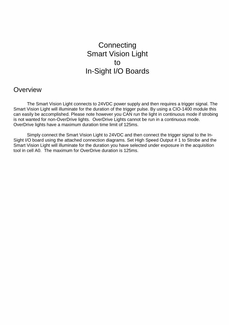
Overview
The Smart Vision Light connects to 24VDC power supply and then requires a trigger signal. The Smart Vision Light will illuminate for the duration of the trigger pulse. By using a CIO-1400 module this can easily be accomplished. Please note however you CAN run the light in continuous mode if strobing is not wanted for non-OverDrive lights. OverDrive Lights cannot be run in a continuous mode. OverDrive lights have a maximum duration time limit of 125ms.
Simply connect the Smart Vision Light to 24VDC and then connect the trigger signal to the In-
Sight I/O board using the attached connection diagrams. Set High Speed Output # 1 to Strobe and the Smart Vision Light will illuminate for the duration you have selected under exposure in the acquisition tool in cell A0. The maximum for OverDrive duration is 125ms.

Cognex to Smart Light Connections
CIO-1400 Connections LIGHT CONNECTIONS
• Connect +24VDC to SMART LIGHT +24VDC (Brown Wire) • Connect 0VDC to SMART LIGHT Common (Blue Wire) • Connect HS OUT1 to SMART LIGHT Trigger (White Wire) • Connect +24VDC to SMART LIGHT +24VDC (Gray Wire – Analog Intensity Control)
CIO-1400 CONNECTIONS
• Connect HS OUT1 to SMART LIGHT Trigger (White Wire) In-Sight SOFTWARE CONFIGURATION
• Set In-Sight I/O to Expansion Board • Set HS OUT1 to Strobe • Set HS OUT1 Details to FALLING EDGE
Smart Vision Light and camera must share common ground – If separate power supplies are used for the light and camera, grounds must be connected together.
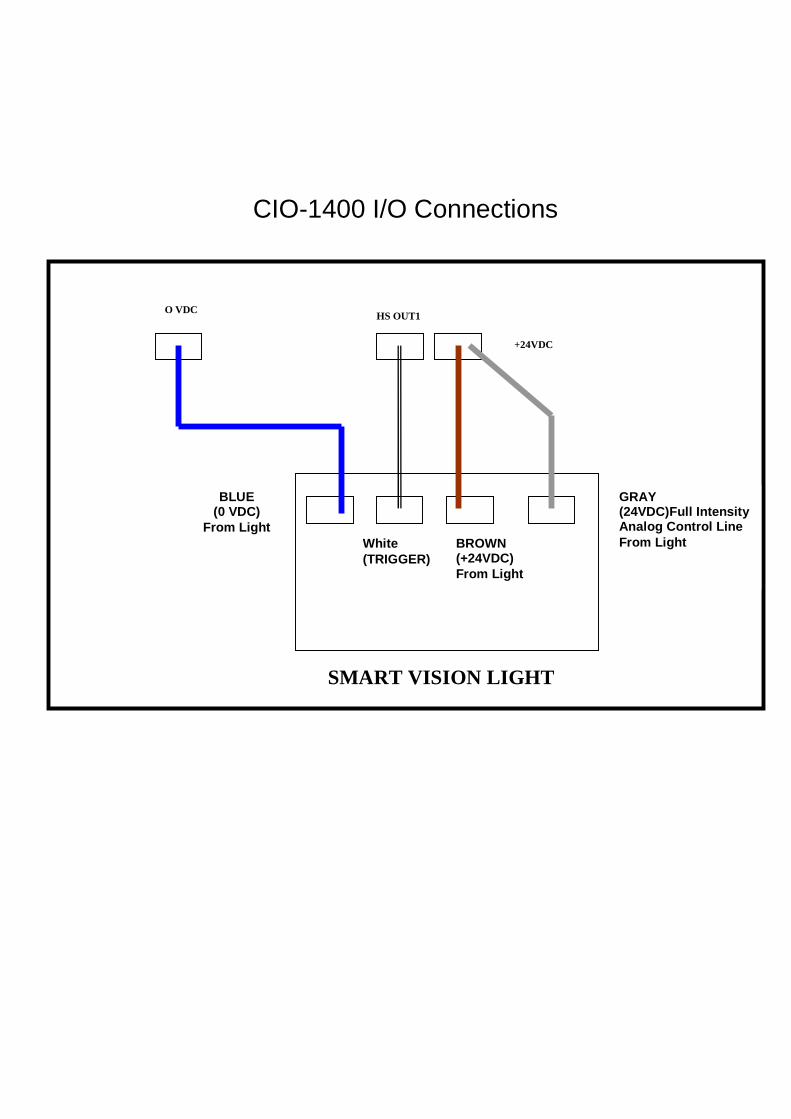
CIO-1400 I/O Connections
BROWN (+24VDC) From Light
White (TRIGGER)
SMART VISION LIGHT
+24VDC
O VDC
BLUE (0 VDC)
From Light
HS OUT1
GRAY (24VDC)Full Intensity Analog Control Line From Light