Embed Size (px)
Citation preview
www.oetiker.com
Connecting Solutions
OETIKER – The experts worldwide
Assembly SolutionsSystem Solutions

Table of Contents
Ear ClampsProduct Groups 167, 105 & 155, 109, 159 & 163, 153 & 154, 101 & 151
Low Profile ClampsProduct Groups 168, 192, 194
Screw Clamps and Universal ClampsProduct Groups 178, 180, 174, 126 & 177
Multi Crimp RingsProduct Group 150
Special ClampsProduct Groups 153, 195, 103, 190
Quick Connectors
Installation Tools
Swing Couplings SC
14
34
50
64
68
70
74
100
IntroductionTechnical IntroductionTypical Product Solutions: Vehicle IndustryTypical Product Solutions: Industry & Trade
2
4
8
10

IntroductionSwiss quality – making the best connections
When you enjoy your daily coffee, your airbag opens when needed, when your train arrives on time and when an operating theatre works perfectly; the Oetiker Group proudly makes its contribution by offering connecting technology for use in almost every aspect of daily life.
The Range: Small parts, great applications. For nearly 70 years the Oetiker Group has been develop-ing, manufacturing and marketing first class connecting products for vehicles, trade and industry worldwide. The company identifies itself as a partner with its customers, and assists at every stage, from selection advice, through production and sales, to service support.
Oetiker understands the needs of its customers, identifies which products can fulfil individual requirements, and how to develop new solutions. Oetiker’s core competence lies primarily in the variety of clamps and rings in a range of materials which are made from tubing or strip. Oetiker manufactures a first class range of products that are outstanding for sealing purposes and for securing hoses and tubes.
Stepless®, self-tensioning and reusable clamps make connections as durable as they are leak-tight, and con-tribute around 90% of the group turnover. Substantial added value is created by the comprehensive range of closing tools. Manufactured in our own works, they en-sure qualified installation and optimum product perform-ance. Electronically controlled installation tools guarantee verified clamp and ring closure at all times.
Innovative Quick Connectors supplement our range of clamps: They are used to provide simple, fast and reliable fastenings and connections for tubes, hoses and for other, safety-relevant components.
Oetiker also offers a comprehensive assortment of cou-plings and related items especially for compressed-air systems, and, for the chemical industry, couplings for the
transport of gaseous media that can be operated without causing risk: on one hand, efficient, energy-saving Swing Couplings with unrestricted bores, which are compatible with most common adaptors & nipples and on the other hand, safe and reliable quick-connection couplings with two-stage disconnection.
In addition, Oetiker is the specialist for complete com-pressed-air systems and can provide you with a complete installation from a single source. Not just couplings, but pipe work, maintenance units, hoses, hose reels, blow guns and other associated accessories.
Finally, Allert, a Group company based in Germany, pro-ducing stamped and formed parts, hinged steel belts, and conveyor chains in numerous versions and to the highest quality standards.
Swiss Quality. In tune with the times and in closecontact with our customers.Oetiker stakes its reputation on the success and satis-faction of its customers – based on Swiss quality and reliability, with versatility and safety as well. As a supplier of integrated systems, the company supplies high quality, technically advanced, proven and innovative products in numerous variants for almost any conceivable appli-cation. The brand name is registered, and most Oetiker products are patented. Every part supplied by the Oetiker Group is backed by Swiss technology – locally manu-factured and customer-oriented.
The Philosophy: Efficient, flexible and innovative.At the Group headquarters in Horgen, near Zurich, Oetiker has its own research and development department. It works closely with Oetiker Group application centers in the USA, Europe, and Asia Pacific and is able to track market trends and respond to customer-specific require-ments. The products used throughout the world are de-veloped and optimized in Horgen using know-how and experience accumulated over many years, and, whether

Introduction 2 / 3
as part of general product improvement or the develop-ment of individual solutions tailored to customer needs, always in the shortest possible time.
Oetiker places equal value on the continuous improve-ment of manufacturing processes, of production equip-ment and technologies, which are always state-of-the-art. Quality assurance is a part of every operation, whether in production, as part of an individual service, or a com-prehensive service. Only in this way can Oetiker’s recog-nizable quality be made available without restrictions at any location worldwide.
All production companies of the Oetiker Group are cer-tified according to ISO/TS 16949 and ISO 9001 standards and to the environment norm ISO 14001.
The Oetiker Group: A global player.And local everywhere.Oetiker is globally active and locally present in all mar-kets. Headquartered and managed in Switzerland, the Group is built on a network of 17 local branches and in total a thousand employees, with production and sales companies in Europe, the USA, Canada, China, India and Japan. This enables the Oetiker Group to adapt its range of products precisely to customers’ requirements and the local environment – to the market, to the climate, both geographically and culturally. Selected dealers ensure that Oetiker products are available in over 40 countries worldwide.
The Story: Continued success since 1943.It all began with an ear: in 1943 the company’s founder, Hans Oetiker, invented the first ear clamp. This was an innovation that won him worldwide recognition. Still to-day – continually developed and modified – it remains Oetiker’s core product. Over the years the inventive spirit and the will to optimize have created a unique portfolio of products for all manner and varieties of applications. In spite of great success and constant growth, Oetiker
remains a traditional enterprise and is still today owned by the founder’s family.
The Social Aspect: Where people work,humanity counts.The greatest capital asset of the Oetiker Group are its employees, and the individual has appropriate impor-tance in the company’s culture. Safety at work and health protection are central concerns, as are systematic train-ing, sound education and continual advanced learning. A commitment that pays rewarding dividends in the long run. Because only people who are competent, who act responsibly, and who enjoy their work can contribute exceptional performance.
The Environment: Consideration pays. For everyone.Environmental protection is an important part of the company’s strategy. Wherever possible we use recyclable materials and, avoid the need for chemical additives. The use of sustainable work processes and the careful treatment of resources, especially energy and raw ma-terials, are equally important. Oetiker goes further still: Every new process and every new material is investigated well before it is introduced to see how it affects planning, production and sales; to find out what lasting effects it will have for employees and customers, and to consider how ecological compatibility can be combined with safety.

OETIKER Ear Clamp with dimple – the originalThe OETIKER system has the ear with a dimple. The geometry of the closed ear is kept very low, which increases the clamping force and creates a spring effect when the hose material expands or contracts in response to thermal or mechanical influences such as temperature, vibration, etc.
Technical introduction MaterialsOnly the very highest quality is used in the manufacture of OETIKER Clamps and Rings. The standard material used for the majority of products is stainless steel. The chromium-nickel content of the stainless steel gives excellent corrosion resistance when exposed to a variety of aggressive environmental influences, both atmos-pheric and aqueous. The specific mechanical and phys-ical characteristics of these materials guarantee high strength and excellent stability.
Width
Dimple
Clamp ear(closing element)
Thickness
Burr-free strip edgesBy having its own narrow strip production, OETIKER can guarantee burr-free strip edges. These unique production processes, on the one hand, lower the risk of damage to parts being clamped and, on the other, reduce the danger of injury through heedless handling.
The difference from the edges of conventional strip is hard to see, but technically very significant.
OETIKER
Others
Nominal diameter
4 / 5Technical introduction
Tolerance compensationBy closing the clamp ear with a recommended, uniform force – withforce priority – component toler-ances within the working range of aStepless® Ear Clamp can be com-pensated.
Dimensions, identification and orderingOETIKER Clamps and Rings are manufactured to metric dimensions. For identification purposes, the nominal diameter is stamped on each product. For example, “145” stands for an open (nominal) clamp diameter of 14.5 mm.
As a general rule, a nominal diameter should be chosen so that the outside diameter of the elastic hose (when assembled onto the connecting part e.g. a hose nozzle) is slightly larger than the middle of the clamping range.
Always quote the 8-digit part number when ordering (see product pages).
The data in this catalogue are based on many years experience. They are intended for reference, not as design specifications.
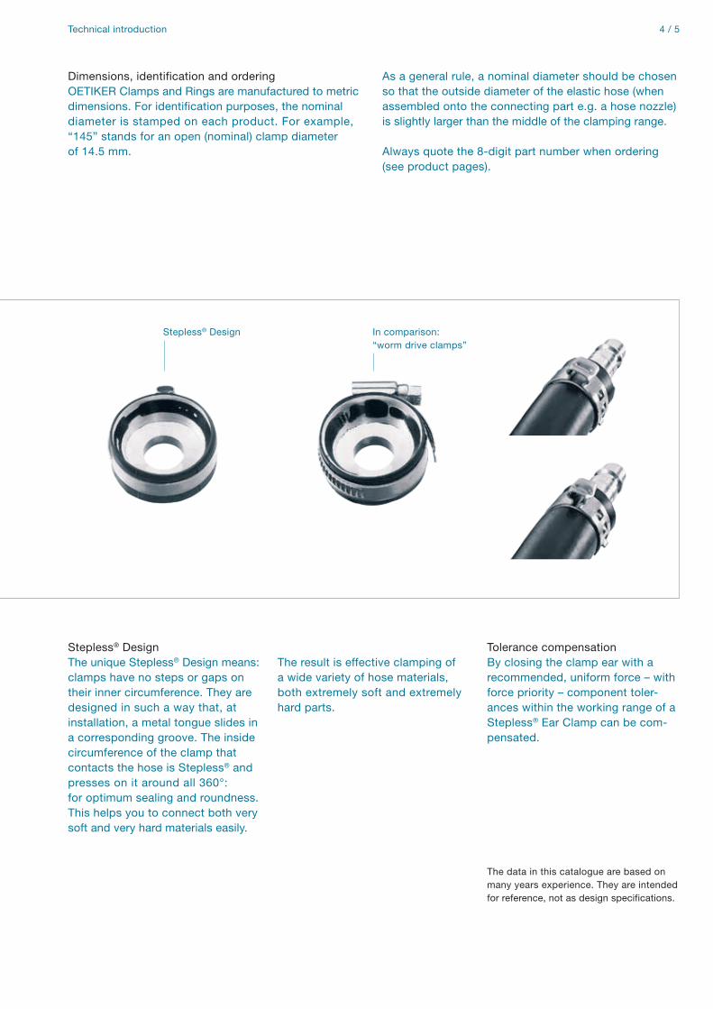
Stepless® Design The unique Stepless® Design means: clamps have no steps or gaps on their inner circumference. They are designed in such a way that, at installation, a metal tongue slides in a corresponding groove. The inside circumference of the clamp that contacts the hose is Stepless® and presses on it around all 360°: for optimum sealing and roundness. This helps you to connect both very soft and very hard materials easily.
The result is effective clamping of a wide variety of hose materials, both extremely soft and extremely hard parts.
Stepless® Design In comparison:“worm drive clamps”

Zurich

Horgen: OETIKERHeadquarters Switzerland
PG 167 PG 167
PG 168 PG 168
PG 192 PG 192 PG 192
PG 194 PG 194
PG 126 & 177 PG 126 & 177 PG 126 & 177
PG 178 PG 178
PG 180
PG 150 PG 150 PG 150
PG 167Stepless® Ear Clamps
Stepless® Low Profile Clamps
Stepless® Low Profile Clamps
Clamps ER
Worm Drive Clamps
Stepless® Screw Clamps
MINI Worm Drive Clamps
Multi Crimp Rings
1-Ear Clamp with stud
1-Ear Clamp SV
1-Ear Clamp “Open End”
PG 167
PG 168
PG 192
PG 194
PG 126 & 177
PG 178
PG 180
PG 150
PG 103
PG 153
PG 195
p. 16
p. 36
p. 44
p. 48
p. 62
p. 52
p. 56
p. 66
p. 69
p. 68
p. 69
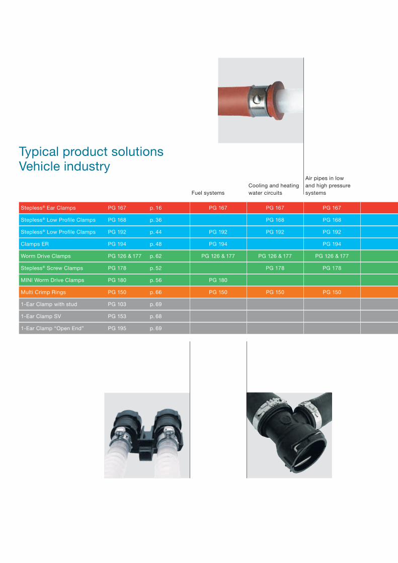
Typical product solutionsVehicle industry
Fuel systemsCooling and heating water circuits
Air pipes in low and high pressure systems

8 / 9Typical product solutions Vehicle industry
PG 168 PG 168 PG 168
PG 192 PG 192 PG 192 PG 192
PG 194 PG 194
PG 126 & 177 PG 126 & 177 PG 126 & 177
PG 178
PG 180
PG 150 PG 150 PG 150 PG 150 PG 150 PG 150
PG 103 PG 103
PG 153
PG 195 PG 195
PG 167 PG 167 PG 167 PG 167 PG 167 PG 167
Oil pipesCardan shafts/drive shafts Steering systems Exhaust systemsAirbag systems Other applications
PG 101 & 151PG 153 & 154 PG 153 & 154 PG 153 & 154
PG 153 & 154PG 167 PG 167 PG 167
PG 167 PG 126 & 177
PG 126 & 177
PG 180
p. 28 p. 29 p. 28 p. 28
p. 16 p. 28
p. 16
p. 62
p. 54
p. 16
p. 62
p. 16
PG 101 & 151 PG 101 & 151 PG 101 & 151 PG 174
PG 153 & 154 PG 153 & 154 PG 167 PG 126 & 177
PG 105 & 155 PG 167 PG 178
PG 109, 159 & 163 PG 174
PG 167 PG 126 & 177
PG 174
PG 126 & 177
PG 180
p. 29 p. 29 p. 20 p. 58
p. 28 p. 28 p. 16 p. 62
p. 52p. 20 p. 16
p. 24 p. 58
p. 16 p. 62
p. 58
p. 62
p. 56
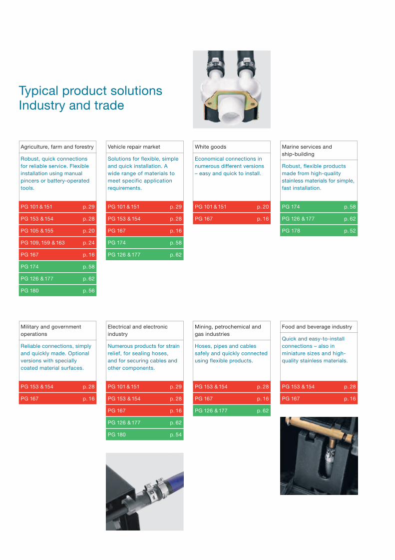
Robust, quick connections for reliable service. Flexible installation using manual pincers or battery-operated tools.
Solutions for flexible, simple and quick installation. A wide range of materials to meet specific application requirements.
Economical connections in numerous different versions – easy and quick to install.
Robust, flexible products made from high-quality stainless materials for simple, fast installation.
Agriculture, farm and forestry Vehicle repair market White goods Marine services and ship-building
Typical product solutionsIndustry and trade
Military and government operations
Food and beverage industryMining, petrochemical and gas industries
Electrical and electronic industry
Reliable connections, simply and quickly made. Optional versions with specially coated material surfaces.
Numerous products for strain relief, for sealing hoses, and for securing cables and other components.
Hoses, pipes and cables safely and quickly connected using flexible products.
Quick and easy-to-install connections – also in miniature sizes and high-quality stainless materials.

10 / 11Typical product solutions Industry and trade
PG 153 & 154 p. 28
PG 153 & 154 PG 101 & 151 PG 153 & 154PG 101 & 151
PG 167 PG 153 & 154 PG 167PG 153 & 154
PG 126 & 177 PG 167 PG 126 & 177PG 167
PG 180 PG 180 PG 178PG 174
PG 194 PG 194PG 126 & 177
p. 28
p. 16
p. 62
p. 56
p. 48
p. 29
p. 28
p. 16
p. 58
p. 62
p. 29
p. 28
p. 16
p. 56
p. 48
p. 28
p. 16
p. 62
p. 52
Construction, sanitary Maintenance, repair and service
Medical, chemical and pharmaceutical industry
Train and aviation industry
Welding
Secure connections, simply and quickly made. Can be installed using manual pincers or battery-operated tools.
Robust, quickly installed connections for many years reliable service.
Suitable, secure connections – also in miniature sizes and high-quality stainless materials.
Robust, quickly installed connections, including special lightweight versions. Flexible installation using battery-operated tools.
Safe, quick and permanent hose connections.

Fast and simple installation
High, adaptable radial forces
Compensate for component tolerances
Visible deformation of the ear provides evidence of proper closure
Reusable: can be repeatedly opened and re-installed*
Low installed height, minimum space requirement
Low imbalance on rotating parts
Tolerance compensation*
Product families Ear Clamps Low profile clamps/Adjustable clamps
p. 14 p. 34
* depending on the product type

12 / 13Product families Overview
Constant, uniform, circumferentialcompression
Minimum space requirement, no imbalance on rotating parts
Flexible diameter reduction up to 9 mm*
Aluminium model – lightweight
Reusable
Large clamping range: can be set to several different nominal diameters*
Fast and simple installation
Compensate for diameter changes due to thermal expansion
1-Ear Clamps with stud
Stable mountings for components with circular cross-sections
Open clamps: simple, radial installation for ergonomic handling
Application-specific fastenings for exhaust systems
Multi Crimp RingsScrew clamps, worm drive clampsand universal clamps
Special clamps
p. 50 p. 64 p. 68
* depending on the product type * depending on the product type

360° Stepless®:+ Uniform compression or uniform surface pressureClamp ear:+ Compensates for component tolerances+ Adjustable surface pressureDimple:+ Increased clamping force+ Spring-effect compensates for changes in diameter due to thermal expansion
Mechanical interlock:+ Allows use of pre-coated materialClamp ear:+ Fast and simple installation+ Visible deformation provides evidence of proper closure
Ear Clamps Stepless® Ear ClampsPG 167
1-Ear Clamp with mechanical interlockPG 105 & 155
p. 16 p. 20
OETIKER will be pleased to helpyou find the correct choice for your application. Send sample parts and all relevant information for your specific application to OETIKER, and you will receive recommen-dations for product type, diameter, and method of installation.

14 / 15
Choice of engagement positions:+ Clamp can be adjusted to several nominal diametersInner ring with radial guidance:+ Effective and powerful all-round sealing
Compact one-piece clamps:+ Robust, secure connections+ Minmum sizes
With insert:+ Pre-shaped insert+ Effective and powerful all-round sealing
2-Ear version:+ Extended clamping rangeClamp ear:+ Fast and simple installation+ Visible deformation of clamp ear provides evidence of proper closure
Ear Clamps Overview
1-Ear ClampsPG 153 & 154
Adjustable ClampsPG 109, 159 & 163
2-Ear ClampsPG 101 & 151
p. 24 p. 28 p. 29

Ear Clamps Stepless® Ear Clamps Product Group 167
Stepless® Ear ClampsProduct Group 167
Material thicknessStepless® Ear Clamps are produced in nominal widths and thick-nesses. The selected material dimensions for a specific appli-cation are based on the stress required to obtain an adequate seal or load.
Clamp ear (closing element)The maximum diameter reduction is proportional to the open “ear” width (s).
The theoretical maximum reduction in diameter is given by the formula:
Material167 Stainless Steel, Material no. 1.4301/UNS S30400Optional alternative materials
Standard SeriesSize range width x thickness 6.5 – 11.8 mm 5.0 x 0.5 mm11.9 – 120.5 mm 7.0 x 0.6 mm21.0 – 120.5 mm 9.0 x 0.6 mm
Heavy Duty SeriesSize range width x thickness24.5 – 120.5 mm 10.0 x 0.8 mm62.0 – 120.5 mm 10.0 x 1.0 mm
Some sizes are only available if an appropriate minimum quantity is ordered. Customer specific sizes available on request.
Narrow band: concentrates transmission of clamping force, less weightStepless over 360°: uniform compression or uniform surface pressureClamp ear: compensates for component tolerances, adjustable surface pressureDimple: increases clamping force, spring-effect compensates for changes in diameter due to thermal expansionSpecially formed strip edges: reduced risk of damage to parts being clamped
Max. diameter reduction =Ear-width (s)
π
Tongue-in-groove designInterlock
Ear width (s)
The data in this catalogue are based on many years experience. They are intended for reference, not as design specifications.

16 / 17Ear Clamps Stepless® Ear Clamps Product Group 167
Note: the above sketch shows the appearance of a closed “ear” (s’); it does not necessarily indicate an effective closed assembly.
As a rule, the clamp nominal diameter should be selected so that the outside diameter of the hose, after it has been pushed on to the component to which it is to be fastened (e.g. a hose nipple), is approximately in the middle of the diameter range of the chosen clamp. A clamp can only be considered adequately closed when the ear width (s) has been reduced by at least 40%, and the correct closing force was used for assembly. Further information with assembly recommendations and closing force is available.
Mechanical interlockThe interlock is a mechanical system for joining the clamp ends to permit closure. Some interlock designs can be opened for radial installation prior to closure.
Assembly recommendationsThe clamp “ear” is deformed with a constant tool jaw force – this practice is referred to as “force priority closure”. This assembly method ensures that a uniform and repeatable stress is applied to the joint in addition to a consistent tensile force on the clamp interlock. Employing this methodology when closing a 167 series clamp will compensate for any component tolerance variations, and ensure that the clamp applies a constant radial force to the application. Fluctuations in component tolerances are absorbed by variations in the “ear” gap (s’). Clamp installation monitoring and process data collection are available by incorporating an “Electronically Controlled Pneumatic Power Tool” OETIKER ELK 01 in the assembly process.
Closing forceThe closing force must be chosen to give the required material compression or surface pressure and should be qualified by dimensional evaluation and experiment. The resistance against the clamp equals the applied force, so the closing force is greatly reduced when compressing a soft material. The table below gives the average applied closing force for clamp and material dimensions when compressing and sealing relatively hard synthetic materials.
Rotation diameterThe rotation diameter (RD) of an assembled clamp can be critical design information for applications that rotate in close proximity to adjacent components. Many factors can influence this final assembly diameter including compression, “ear” gap “s” and material thickness. It is recommended that all variables be considered and evaluated prior to specifying a rotating diameter.
ImportantAdding a depressor to the installation tool, for the purpose of reducing the ear height, can cause excessive stress in the ear radii and is not recommended.
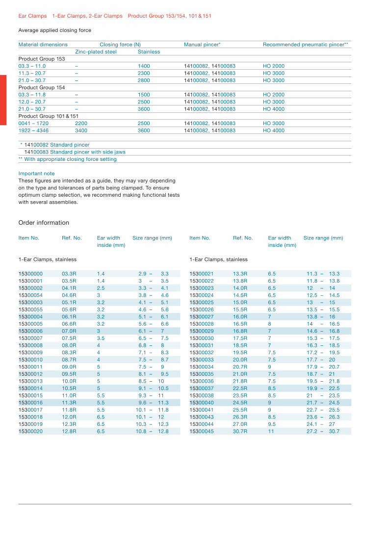
Average applied closing force
Material dimensions Size Closing force Manual pincer* Recommended pneumatic pincer** 5 x 0.5 mm 6.5 – 11.8 1000 N 14100082, 14100083 HO 2000 5 x 0.6 mm 18.5 – 100.0 1700 N 14100082, 14100083 HO 2000 7 x 0.6 mm 11.9 – 17.5 2100 N 14100082, 14100083 HO 2000 – HO 3000 17.8 – 120.5 2400 N 14100082, 14100083 HO 3000 7 x 0.8 mm 2800 N 14100082, 14100083 HO 3000 – HO 4000 9 x 0.6 mm 2800 N 14100082, 14100083 HO 3000 – HO 4000 9 x 0.8 mm 4100 N 14100097, 14100098 HO 5000 – HO 7000 10 x 0.6 mm 2900 N 14100097, 14100098 HO 5000 – HO 7000 10 x 0.8 mm 5000 N 14100097, 14100098 HO 5000 – HO 700010 x 1.0 mm 7000 N 14100097, 14100098 HO 700012 x 1.0 mm 8500 N 14100097, 14100098 HO 7000
** 14100082 Standard pincer 14100097 Clamping Tool 14100083 Standard pincer with side jaws 14100098 Torque wrench** With appropriate closing force setting
Important noteThese figures are intended as a guide, they may vary depending on the type and tolerances of parts being clamped. To ensure optimum clamp selection, we recommend making functional tests with several assemblies.
(s’)
RD

Ear Clamps Stepless® Ear Clamps Product Group 167
Order information
Size range (mm)
5.3 – 6.5 5.8 – 7 6.8 – 8 7 – 8.7 7.3 – 9 7.8 – 9.5 8.3 – 10 8.8 – 10.5 9.2 – 10.9 9.6 – 11.3 10.1 – 11.8
9.4 – 11.9 9.8 – 12.3 10.3 – 12.8 10.8 – 13.3 11.3 – 13.8 11.5 – 14 11.7 – 14.2 12 – 14.5 12.3 – 14.8 12.8 – 15.3 13.2 – 15.7 13.5 – 16 13.7 – 16.2 14.1 – 16.6 14.3 – 16.8 14.5 – 17 15 – 17.5 14.6 – 17.8 14.8 – 18 15.3 – 18.5 16 – 19.2 16.6 – 19.8 17.8 – 21 19.4 – 22.6 20.3 – 23.5 20.9 – 24.1 22.4 – 25.6 23.9 – 27.1 25.4 – 28.6 26.9 – 30.1 27.6 – 30.8 28.4 – 31.6 29.9 – 33.1 31.4 – 34.6 32.9 – 36.1 34.4 – 37.6 34.9 – 38.1 36.4 – 39.6 37.8 – 41
Size range (mm)
39.3 – 42.5 40.8 – 44 42.3 – 45.5 43.8 – 47 45.3 – 48.5 46.8 – 50 48.3 – 51.5 49.8 – 53 51.3 – 54.5 52.8 – 56 54.3 – 57.5 55.8 – 59 57.3 – 60.5 58.8 – 62 60.3 – 63.5 61.8 – 65 63.3 – 66.5 64.8 – 68 66.3 – 69.5 67.8 – 71 69.3 – 72.5 70.8 – 74 72.3 – 75.5 73.8 – 77 75.3 – 78.5 76.8 – 80 78.3 – 81.5 79.8 – 83 81.3 – 84.5 82.8 – 86 84.3 – 87.5 85.8 – 89 87.3 – 90.5 88.8 – 92 90.3 – 93.5 91.8 – 95 93.3 – 96.5 94.8 – 98 96.3 – 99.5 97.8 – 101 99.3 – 102.5 100.8 – 104 102.3 – 105.5 103.8 – 107 105.3 – 108.5 106.8 – 110 108.3 – 111.5 109.8 – 113 111.3 – 114.5 112.8 – 116 114.3 – 117.5 115.8 – 119 117.3 – 120.5
Item No. Ref. No. Ear width inside (mm)
Band width 5 mm, thickness 0.5 mm (505R)
16702488 006.5-505R 416700001 007.0-505R 416700002 008.0-505R 416700003 008.7-505R 5.516702491 009.0-505R 5.516700004 009.5-505R 5.516700005 010.0-505R 5.516700006 010.5-505R 5.516702492 010.9-505R 5.516700007 011.3-505R 5.516700008 011.8-505R 5.5
Band width 7 mm, thickness 0.6 mm (706R)
16702951 011.9-706R 816700009 012.3-706R 816702493 012.8-706R 816700010 013.3-706R 816700011 013.8-706R 816700012 014.0-706R 816702864 014.2-706R 816700013 014.5-706R 816700014 014.8-706R 816700015 015.3-706R 816700016 015.7-706R 816702998 016.0-706R 816702494 016.2-706R 816702495 016.6-706R 816702496 016.8-706R 816700017 017.0-706R 816702497 017.5-706R 816700018 017.8-706R 1016700019 018.0-706R 1016700020 018.5-706R 1016700110 019.2-706R 1016702498 019.8-706R 1016700024 021.0-706R 1016700026 022.6-706R 1016700028 023.5-706R 1016700029 024.1-706R 1016700031 025.6-706R 1016700033 027.1-706R 1016700035 028.6-706R 1016702047 030.1-706R 1016700039 030.8-706R 1016700040 031.6-706R 1016700042 033.1-706R 1016700044 034.6-706R 1016700046 036.1-706R 1016700048 037.6-706R 1016700050 038.1-706R 1016700052 039.6-706R 1016700053 041.0-706R 10
Item No. Ref. No. Ear width inside (mm)
Band width 7 mm, thickness 0.6 mm (706R)
16700054 042.5-706R 1016700055 044.0-706R 1016700056 045.5-706R 1016700057 047.0-706R 1016700058 048.5-706R 1016700059 050.0-706R 1016700060 051.5-706R 1016700061 053.0-706R 1016700062 054.5-706R 1016700063 056.0-706R 1016700064 057.5-706R 1016700065 059.0-706R 1016700066 060.5-706R 1016700067 062.0-706R 1016700068 063.5-706R 1016700069 065.0-706R 1016700070 066.5-706R 1016700071 068.0-706R 1016700072 069.5-706R 1016700073 071.0-706R 1016700074 072.5-706R 1016700075 074.0-706R 1016700076 075.5-706R 1016700077 077.0-706R 1016700078 078.5-706R 1016700079 080.0-706R 1016700080 081.5-706R 1016700081 083.0-706R 1016700082 084.5-706R 1016700083 086.0-706R 1016700084 087.5-706R 1016700085 089.0-706R 1016700086 090.5-706R 1016700087 092.0-706R 1016700088 093.5-706R 1016700089 095.0-706R 1016700090 096.5-706R 1016700091 098.0-706R 1016700092 099.5-706R 1016700093 101.0-706R 1016700094 102.5-706R 1016700095 104.0-706R 1016700096 105.5-706R 1016700097 107.0-706R 1016700098 108.5-706R 1016700099 110.0-706R 1016700100 111.5-706R 1016700101 113.0-706R 1016700102 114.5-706R 1016700103 116.0-706R 1016700104 117.5-706R 1016700105 119.0-706R 1016700106 120.5-706R 10
18 / 19Ear Clamps Stepless® Ear Clamps Product Group 167
Order information
Size range (mm)
17.8 – 21 19.4 – 22.6 20.3 – 23.5 20.9 – 24.1 22.4 – 25.6 23.9 – 27.1 25.4 – 28.6 26.9 – 30.1 27.6 – 30.8 28.4 – 31.6 29.9 – 33.1 31.4 – 34.6 32.9 – 36.1 34.4 – 37.6 34.9 – 38.1 36.4 – 39.6 37.8 – 41 39.3 – 42.5 40.8 – 44 42.3 – 45.5 43.8 – 47 45.3 – 48.5 46.8 – 50 48.3 – 51.5 49.8 – 53 51.3 – 54.5 52.8 – 56 54.3 – 57.5 55.8 – 59 57.3 – 60.5 58.5 – 62 60.3 – 63.5 61.8 – 65 63.3 – 66.5 64.8 – 68 66.3 – 69.5 67.8 – 71 69.3 – 72.5 70.8 – 74 72.3 – 75.5 73.8 – 77 75.3 – 78.5 76.8 – 80 78.3 – 81.5 79.8 – 83 81.3 – 84.5 82.8 – 86 84.3 – 87.5 85.8 – 89 87.3 – 90.5 88.8 – 92 90.3 – 93.5 91.8 – 95
Size range (mm)
93.3 – 96.5 94.8 – 98 96.3 – 99.5 97.8 – 101 99.3 – 102.5 100.8 – 104 102.3 – 105.5 103.8 – 107 105.3 – 108.5 106.8 – 110 108.3 – 111.5 109.8 – 113 111.3 – 114.5 112.8 – 116 114.3 – 117.5 115.8 – 119 117.3 – 120.5
Item No. Ref. No. Ear width inside (mm)
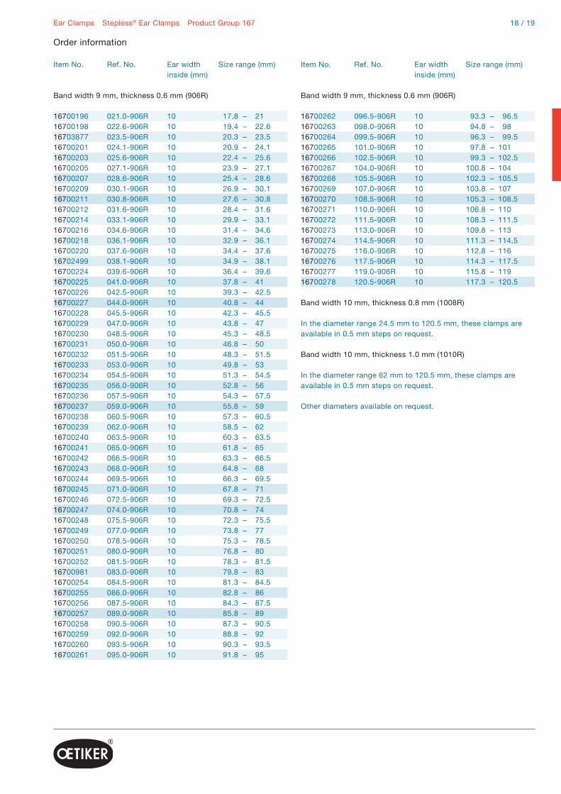
Band width 9 mm, thickness 0.6 mm (906R)
16700196 021.0-906R 1016700198 022.6-906R 1016703877 023.5-906R 1016700201 024.1-906R 1016700203 025.6-906R 1016700205 027.1-906R 1016700207 028.6-906R 1016700209 030.1-906R 1016700211 030.8-906R 1016700212 031.6-906R 1016700214 033.1-906R 1016700216 034.6-906R 1016700218 036.1-906R 1016700220 037.6-906R 1016702499 038.1-906R 1016700224 039.6-906R 1016700225 041.0-906R 1016700226 042.5-906R 1016700227 044.0-906R 1016700228 045.5-906R 1016700229 047.0-906R 1016700230 048.5-906R 1016700231 050.0-906R 1016700232 051.5-906R 1016700233 053.0-906R 1016700234 054.5-906R 1016700235 056.0-906R 1016700236 057.5-906R 1016700237 059.0-906R 1016700238 060.5-906R 1016700239 062.0-906R 1016700240 063.5-906R 1016700241 065.0-906R 1016700242 066.5-906R 1016700243 068.0-906R 1016700244 069.5-906R 1016700245 071.0-906R 1016700246 072.5-906R 1016700247 074.0-906R 1016700248 075.5-906R 1016700249 077.0-906R 1016700250 078.5-906R 1016700251 080.0-906R 1016700252 081.5-906R 1016700981 083.0-906R 1016700254 084.5-906R 1016700255 086.0-906R 1016700256 087.5-906R 1016700257 089.0-906R 1016700258 090.5-906R 1016700259 092.0-906R 1016700260 093.5-906R 1016700261 095.0-906R 10
Item No. Ref. No. Ear width inside (mm)
Band width 9 mm, thickness 0.6 mm (906R)
16700262 096.5-906R 1016700263 098.0-906R 1016700264 099.5-906R 1016700265 101.0-906R 1016700266 102.5-906R 1016700267 104.0-906R 1016700268 105.5-906R 1016700269 107.0-906R 1016700270 108.5-906R 1016700271 110.0-906R 1016700272 111.5-906R 1016700273 113.0-906R 1016700274 114.5-906R 1016700275 116.0-906R 1016700276 117.5-906R 1016700277 119.0-906R 1016700278 120.5-906R 10
Band width 10 mm, thickness 0.8 mm (1008R)
In the diameter range 24.5 mm to 120.5 mm, these clamps areavailable in 0.5 mm steps on request.
Band width 10 mm, thickness 1.0 mm (1010R)
In the diameter range 62 mm to 120.5 mm, these clamps areavailable in 0.5 mm steps on request.
Other diameters available on request.
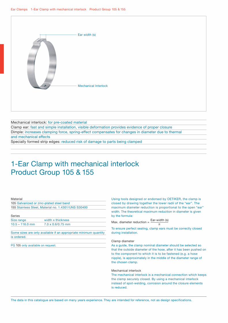
Mechanical interlock: for pre-coated materialClamp ear: fast and simple installation, visible deformation provides evidence of proper closureDimple: increases clamping force, spring-effect compensates for changes in diameter due to thermaland mechanical effectsSpecially formed strip edges: reduced risk of damage to parts being clamped
Using tools designed or endorsed by OETIKER, the clamp is closed by drawing together the lower radii of the “ear”. The maximum diameter reduction is proportional to the open “ear” width. The theoretical maximum reduction in diameter is given by the formula:
To ensure perfect sealing, clamp ears must be correctly closed during installation.
Clamp diameterAs a guide, the clamp nominal diameter should be selected so that the outside diameter of the hose, after it has been pushed on to the component to which it is to be fastened (e.g. a hose nipple), is approximately in the middle of the diameter range of the chosen clamp.
Mechanical interlock The mechanical interlock is a mechanical connection which keeps the clamp securely closed. By using a mechanical interlock instead of spot-welding, corrosion around the closure elements is reduced.
Material105 Galvanized or zinc-plated steel band155 Stainless Steel, Material no. 1.4301/UNS S30400
SeriesSize range width x thickness10.5 – 116.0 mm 7.0 x 0.6/0.75 mm
Some sizes are only available if an appropriate minimum quantity is ordered.
PG 105 only available on request.
Ear Clamps 1-Ear Clamp with mechanical interlock Product Group 105 & 155
1-Ear Clamp with mechanical interlockProduct Group 105 & 155
The data in this catalogue are based on many years experience. They are intended for reference, not as design specifications.
Mechanical Interlock
Ear width (s)
Max. diameter reduction =Ear-width (s)
π
20 / 21Ear Clamps 1-Ear Clamp with mechanical interlock Product Group 105 & 155
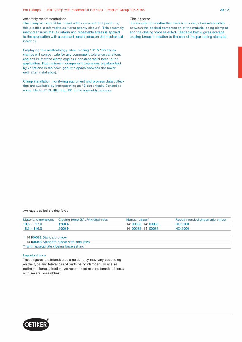
Assembly recommendationsThe clamp ear should be closed with a constant tool jaw force, this practice is referred to as “force priority closure”. This assembly method ensures that a uniform and repeatable stress is applied to the application with a constant tensile force on the mechanical interlock.
Employing this methodology when closing 105 & 155 series clamps will compensate for any component tolerance variations, and ensure that the clamp applies a constant radial force to the application. Fluctuations in component tolerances are absorbed by variations in the “ear” gap (the space between the lower radii after installation).
Clamp installation monitoring equipment and process data collec-tion are available by incorporating an “Electronically Controlled Assembly Tool” OETIKER ELK01 in the assembly process.
Closing forceIt is important to realize that there is in a very close relationship between the desired compression of the material being clamped and the closing force selected. The table below gives average closing forces in relation to the size of the part being clamped.
Average applied closing force
Material dimensions Closing force GALFAN/Stainless Manual pincer* Recommended pneumatic pincer**10.5 – 17.0 1200 N 14100082, 14100083 HO 200018.5 – 116.0 2000 N 14100082, 14100083 HO 2000
** 14100082 Standard pincer 14100083 Standard pincer with side jaws** With appropriate closing force setting
Important noteThese figures are intended as a guide, they may vary depending on the type and tolerances of parts being clamped. To ensure optimum clamp selection, we recommend making functional tests with several assemblies.

Ear Clamps 1-Ear Clamp with mechanical interlock Product Group 105 & 155
Order information
Size range (mm)
8.9 – 10.5 9.7 – 11.3 10.4 – 12.3 11.4 – 13.3 11.5 – 13.5 11.9 – 13.8 11.9 – 14 12.6 – 14.5 13.5 – 15.7 15.1 – 17 15.7 – 18.5 17 – 19.8 18.2 – 21 19.8 – 22.6 21.3 – 24.1 22.8 – 25.6 24 – 27.1 25.5 – 28.6 27 – 30.1 28.5 – 31.6 30 – 33.1 31.5 – 34.6 33 – 36.1 34.5 – 37.6 35 – 38.1 36.5 – 39.6
Item No. Ref. No. Ear width inside (mm)
1-Ear Clamp with mechanical Interlock, stainlessBand width 7 mm, thickness 0.6 mm
15500000 0105.0R 515500001 0113.0R 515500002 0123.0R 615500003 0133.0R 615500004 0135.0R 6.515500005 0138.0R 615500006 0140.0R 6.515500007 0145.0R 615500008 0157.0R 7 15500009 0170.0R 615500010 0185.0R 915500011 0198.0R 915500012 0210.0R 915500013 0226.0R 915500014 0241.0R 915500015 0256.0R 915500016 0271.0R 1015500017 0286.0R 1015500018 0301.0R 1015500019 0316.0R 1015500020 0331.0R 1015500021 0346.0R 1015500022 0361.0R 1015500023 0376.0R 1015500024 0381.0R 1015500025 0396.0R 10
Size range (mm)
37.9 – 41 39.4 – 42.5 40.9 – 44 42.4 – 45.5 43.9 – 47 45.4 – 48.5 46.9 – 50 48.4 – 51.5 49.9 – 53 51.4 – 54.5 52.9 – 56 54.4 – 57.5 55.9 – 59 57.4 – 60.5 58.9 – 62 60.4 – 63.5 61.9 – 65 63.4 – 66.5 64.9 – 68 66.4 – 69.5 67.9 – 71 69.4 – 72.5 70.9 – 74 72.4 – 75.5 73.9 – 77 75.4 – 78.5
Item No. Ref. No. Ear width inside (mm)
1-Ear Clamp with mechanical Interlock, stainlessBand width 7 mm, thickness 0.6 mm
15500026 0410.0R 1015500027 0425.0R 1015500028 0440.0R 1015500029 0455.0R 1015500030 0470.0R 1015500031 0485.0R 1015500032 0500.0R 1015500033 0515.0R 1015500034 0530.0R 1015500035 0545.0R 1015500036 0560.0R 1015500037 0575.0R 1015500038 0590.0R 1015500039 0605.0R 1015500040 0620.0R 1015500041 0635.0R 1015500042 0650.0R 1015500043 0665.0R 1015500044 0680.0R 1015500045 0695.0R 1015500046 0710.0R 1015500047 0725.0R 1015500048 0740.0R 1015500049 0755.0R 1015500050 0770.0R 1015500051 0785.0R 10

22 / 23Ear Clamps 1-Ear Clamp with mechanical interlock Product Group 105 & 155
Order information
Size range (mm)
76.9 – 80 78.4 – 81.5 79.9 – 83 81.4 – 84.5 82.9 – 86 84.4 – 87.5 85.9 – 89 87.4 – 90.5 88.9 – 92 90.4 – 93.5 91.9 – 95 93.4 – 96.5 94.9 – 98 96.4 – 99.5 97.9 – 101 99.4 – 102.5 100.9 – 104 102.4 – 105.5 103.9 – 107 105.4 – 108.5 106.9 – 110 108.4 – 111.5 109.9 – 113 111.4 – 114.5 112.9 – 116
Item No. Ref. No. Ear width inside (mm)
1-Ear Clamp with mechanical Interlock, stainlessBand width 7 mm, thickness 0.6 mm
15500052 0800.0R 1015500053 0815.0R 1015500054 0830.0R 1015500055 0845.0R 1015500056 0860.0R 1015500057 0875.0R 1015500058 0890.0R 1015500059 0905.0R 1015500060 0920.0R 1015500061 0935.0R 1015500062 0950.0R 1015500063 0965.0R 1015500064 0980.0R 1015500065 0995.0R 1015500066 1010.0R 1015500067 1025.0R 1015500101 1040.0R 1015500068 1055.0R 1015500102 1070.0R 1015500103 1085.0R 1015500104 1100.0R 1015500105 1115.0R 1015500106 1130.0R 1015500107 1145.0R 1015500069 1160.0R 10

Product Group 159 – Adjustable Clamps:
Version with interlock outsideMay make installation easier
Product Group 109/159 – Adjustable clamp:
Version with interlock inside
Ear Clamps Adjustable Clamps Product Group 109, 159 & 163
Adjustable ClampsProduct Group 109, 159 & 163
Material109 zinc-plated steel band159 & 163 Stainless Steel, Material no. 1.4301/UNS S30400
Adjustable Clamps PG 109Size range width x thickness29.5 – 122.0 mm 7.0 x 0.75 mm29.5 – 122.0 mm 9.0 x 0.75 mm
Adjustable Clamps PG 159Size range width x thickness25.0 – 50.0 mm 7.0 x 0.8 mm*40.0 – 110.0 mm 7.0 x 0.8 mm*
Adjustable Clamps with radial guiding PG 163Size range width x thickness30.0 – 116.0 mm 7.0 x 0.6 mm72.0 – 132.0 mm 9.0 x 0.6 mm
* Diameter range covered by a single clampSome sizes are only available if an appropriate minimum quantity is ordered.
Choice of engagement positions: clamp can be adjusted to several nominal diametersInner ring with radial guidance: effective and powerful all-round sealingClamp ear: simple and fast installation, visible deformation provides evidence of proper closureSpecially formed strip edges: reduced risk of damage to parts being clamped
Interlock
Interlock
PG 109
Multi positioninterlock
Ear width (s)
Self-aligning design(radial guiding)
PG 163 PG 159
The data in this catalogue are based on many years experience. They are intended for reference, not as design specifications.

24 / 25
Using tools designed by OETIKER, the clamp is closed bydrawing together the lower radii of the “ear”. The maximum diameter reduction is proportional to the open “ear” width (s). The theoretical maximum reduction in diameter is given by the formula:
* Adjustable Clamps with radial guiding, 8.5 mm ear-width(2.7 mm theoretical diameter reduction) with Adjustable Clamps PG 159
Multi-position interlockThe interlock consists of one or two load-retaining hooks that withstand tensile loading during closure and a lock tab designed to hold the hooks in their windows prior to closure. With both designs the interlock can be engaged in several positions within the published range. This feature allows a single part to cover a range of diameters.
Adjustable Clamps with radial guiding (self-aligning design)A tab formed on the inner portion of the clamp locates in a slot in the outer band surface. During assembly and closure, the tab slides in the slot and so avoids any step around the inner circumference of the clamp.
Assembly Recommendations
Product Group 163 – Adjustable Clamps with radial guidingThe clamp can be installed axially on the application prior to assembly or alternatively, radially around the assembled compo-nents. For either method, it is important that the hooks and lock tab are engaged in windows giving the smallest possible
Ear Clamps Adjustable Clamps Product Group 109, 159 & 163
diameter, so that the maximum clearance between the assembled components and the inside diameter of the clamp before closure is no greater than 1.5 mm. Each incremental step of the interlock reduces the diameter before closure by 1.6 mm on the “3-step” series, and by 1.05 mm on the “6- step” design.
Product Group 109&159 – Adjustable ClampsPG 109 Adjustable Clamps are supplied pre-shaped and engaged at mid-diameter. PG 159 clamps are supplied flat. The clamp must be shaped prior to assembly. Each incremental step of the interlock reduces the diameter before closure by approximately 1.6 mm. The following assembly steps demonstrate how best to achieve an effective geometry.
The clamp ear of both variants should be closed with constant tool jaw force, this practice is referred to as “force priority closure”. This assembly method ensures that a uniform and repeatable stress is applied to the application with a constant tensile force on the mechanical interlock.
Clamp installation monitoring and process data collection are available by incorporating an “Electronically Controlled Pneumatic Power Tool OETIKER ELK 01” in the assembly process.
Closing forceThe closing force must be chosen to give the required material compression or surface pressure and should be qualified by dimensional evaluation and experiment. The resistance against the clamp equals the applied force, so the closing force is greatly reduced when compressing a soft material. The table below gives the average applied closing force for clamp and material dimensions.
Average applied closing force
Material dimensions Size (mm) Closing force Manual pincer* Recommended pneumatic pincer**Product Group 1097 x 0.75 mm 29.5 – 122 1400 N 14100082, 14100083 HO 20009 x 0.75 mm 29.5 – 122 1800 N 14100082, 14100083 HO 2000Product Group 1597 x 0.8 mm 25.5 – 50 2400 – 2700 N 14100082, 14100083 HO 30007 x 0.8 mm 40.5 – 110 2400 – 2700 N 14100082, 14100083 HO 3000Product Group 1637 x 0.6 mm 30.5 – 50 1800 – 2100 N 14100082, 14100083 HO 2000 – HO 30007 x 0.6 mm 56.5 – 116 2400 – 2700 N 14100082, 14100083 HO 30009 x 0.6 mm 72.5 – 132 2800 – 3200 N 14100082, 14100083 HO 3000
** 14100082 Standard pincer/14100083 Standard pincer with side jaws** With appropriate closing force setting
Important noteThese figures are intended as a guide, they may vary depending on the type and tolerances of parts being clamped. To ensure optimum clamp selection, we recommend making functional tests with several assemblies.
= 3.2 mm(Ear width) 10 mm*
π

Ear Clamps Adjustable Clamps Product Group 109, 159 & 163
PG 159 – Version with interlock outside
PG 109 & 159 – Version with interlock inside
Step 1Pre-shape clamp.
Step 1Pre-shape clamp.
Step 2Determine the clamp length.
Step 2Determine the clamp length. Make sure the end of the clamp passes the “ear”, as shown.
Step 3Cut off the remaining material. To avoid possible injury deburr cut edges with a file.
Step 3Cut off the remaining material. To avoid possible injury deburr cut edges with a file.
Step 4Place the clamp over object. Engage interlocking hooks in tightest window position. Firmly crimp the ear with OETIKER pincers.
Step 4Place the clamp over object. Engage interlocking hooks in tightest window position. Firmly crimp the ear with OETIKER pincers.
Assembly instructions
26 / 27Ear Clamps Adjustable Clamps Product Group 109, 159 & 163
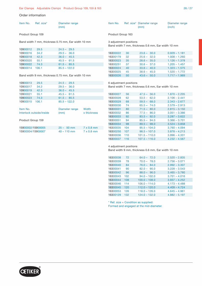
Item No. Ref. size* Diameter range Diameter range (mm) (inch)
Product Group 163
3 adjustment positionsBand width 7 mm, thickness 0.6 mm, Ear width 10 mm
16300022 30 23.6 – 30.0 0.929 – 1.18116300179 32 25.6 – 32.0 1.008 – 1.26016300023 35 28.6 – 35.0 1.126 – 1.37816300251 37 30.6 – 37.0 1.205 – 1.45716300024 40 33.6 – 40.0 1.323 – 1.57516300025 45 38.6 – 45.0 1.520 – 1.77216300026 50 43.6 – 50.0 1.717 – 1.969
6 adjustment positionsBand width 7 mm, thickness 0.6 mm, Ear width 10 mm
16300027 56 47.5 – 56.0 1.870 – 2.20516300028 62 53.5 – 62.0 2.106 – 2.44116300029 68 59.5 – 68.0 2.343 – 2.67716300030 74 65.5 – 74.0 2.579 – 2.91316300031 80 71.5 – 80.0 2.815 – 3.15016300032 86 77.5 – 86.0 3.051 – 3.38616300033 92 83.5 – 92.0 3.287 – 3.62216300051 94 85.5 – 94.0 3.366 – 3.70116300034 98 89.5 – 98.0 3.524 – 3.85816300035 104 95.5 – 104.0 3.760 – 4.09416300250 107 98.5 – 107.0 3.878 – 4.21316300036 110 101.5 – 110.0 3.996 – 4.33116300037 116 107.5 – 116.0 4.232 – 4.567
4 adjustment positionsBand width 9 mm, thickness 0.6 mm, Ear width 10 mm
16300038 72 64.0 – 72.0 2.520 – 2.83516300039 78 70.0 – 78.0 2.756 – 3.07116300040 84 76.0 – 84.0 2.992 – 3.30716300041 90 82.0 – 90.0 3.228 – 3.54316300042 96 88.0 – 96.0 3.465 – 3.78016300043 102 94.0 – 102.0 3.701 – 4.01616300044 108 100.0 – 108.0 3.937 – 4.25216300046 114 106.0 – 114.0 4.173 – 4.48816300045 120 112.0 – 120.0 4.409 – 4.72416300053 126 118.0 – 126.0 4.645 – 4.96116300129 132 124.0 – 132.0 4.882 – 5.197
* Ref. size = Condition as supplied:Formed and engaged at the mid-diameter.
Order information
Item No. Ref. size* Diameter range (mm)
Product Group 109
Band width 7 mm, thickness 0.75 mm, Ear width 10 mm
10900012 29.5 24.5 – 29.510900016 34.2 29.5 – 36.010900018 42.3 36.0 – 45.510900020 55.1 45.5 – 61.510900022 74.3 61.5 – 85.510900014 106.1 85.5 – 122.0
Band width 9 mm, thickness 0.75 mm, Ear width 10 mm
10900013 29.5 24.5 – 29.510900017 34.2 29.5 – 36.010900019 42.3 36.0 – 45.510900021 55.1 45.5 – 61.510900023 74.3 61.5 – 85.510900015 106.1 85.5 – 122.0
Item No. Diameter range Width Interlock outside/inside (mm) x thickness
Product Group 159
15900002/15900005 25 – 50 mm 7 x 0.8 mm15900004/15900007 40 – 110 mm 7 x 0.8 mm

Ear Clamps 1-Ear Clamps Product Group 153/154
1-Ear ClampsProduct Group 153/154
Material153 Stainless Steel, Material no. 1.4301/UNS S30400154 Clamp: Stainless Steel, Material no. 1.4301/UNS S30400 Insert: Stainless Steel, Material no. 1.4310/UNS S30100
Size range153 3.3 – 30.7 mm154 2.9 – 30.0 mm
Some sizes are only available if an appropriate minimum quantity is ordered.
ProcessThe manufacturing process for OETIKER 1-Ear and 2-Ear Clampscommences with the spiral roll-forming and welding of raw material into lengths of tube, a technique developed to obtain a robust, continuous welded ring.
Compact one-piece clamp: for robust, secure connections, miniature sizesClamp ear: fast and simple installation, visible deformation provides evidence of proper closureDeburred edges: reduced risk of damage to parts being clampedWith insertPre-shaped insert: effective and powerful all-round seal
OETIKER 1-Ear Clamps with insertThis type of clamp combines the geometry and properties of the 1-Ear Clamp with an insert made of stainless steel.
These clamps are ideal for demanding applications involving soft or hard rubbers and plastics. The thin-walled insert ring (up to 0.3 mm thick), with an oval protrusion that locates in the ear space, bridges the ear gap and ensures almost uniform compression around the whole circumference of a clamp.
Edge conditionBurrs generated during the shearing and forming processes are entirely eliminated in a barrel-finishing operation.
ClosureBy using an OETIKER closing tool to pinch the clamp ear, the diameter of the clamp is reduced. This diameter reduction is proportional to the ear width.
The maximum reduction in diameter is given by the formula:
Insert
Ear width (s)
The data in this catalogue are based on many years experience. They are intended for reference, not as design specifications.
Max. diameter reduction =Ear-width (s)
π

28 / 29Ear Clamps 2-Ear Clamps Product Group 101 & 151
2-Ear version: extended clamping rangeCompact one-piece clamp: for robust, secure connectionsClamp ear: fast and simple installation, visible deformation provides evidence of proper closureDeburred edges: reduced risk of damage to parts being clamped
Material101 Steel, Material no. 1.0338/SAE 1008/1010, zinc-plated151 Stainless Steel, Material no. 1.4301/UNS S30400
Size range4.1 – 46.0 mm
Some sizes are only available if an appropriate minimum quantity is ordered.
OETIKER 2-Ear ClampsThe ears of these clamps do not have a dimple and nearly double the clamping range, compared to the 1-ear clamp. 2 ears provide a degree of elasticity to accommodate changes in size of the parts being joined, such as that which may be caused by thermal expansion or vibration.
Installation techniques are similar to those for 1-Ear Clamps, but the force applied when closing the second ear may react against the opposing closed ear and make a second crimping operation necessary. For perfect sealing, the ears must be adequately closed during installation.
Assembly recommendationsThe ears of these clamps should be closed with the recommended, uniform force (known as force priority). This method will result in a constant, reproducible stress within the clamp material, without overloading either the clamp or the parts being assembled. The nominal diameter of the clamp should always be chosen so that, when installed with the correct clamping force, the ears are almost closed.
Complete process monitoring and 100% process documentation are available using the “Electronically Controlled Pneumatic Power Tool” OETIKER ELK 01.
Closing forceThe following table shows the average applied closing force for different material dimensions.
2-Ear ClampsProduct Group 101 & 151
Ear width (s)
Ear Clamps 1-Ear Clamps, 2-Ear Clamps Product Group 153/154, 101 & 151
Order information
Average applied closing force
Material dimensions Closing force (N) Manual pincer* Recommended pneumatic pincer** Zinc-plated steel StainlessProduct Group 15303.3 – 11.0 – 1400 14100082, 14100083 HO 200011.3 – 20.7 – 2300 14100082, 14100083 HO 300021.0 – 30.7 – 2800 14100082, 14100083 HO 3000Product Group 15403.3 – 11.8 – 1500 14100082, 14100083 HO 200012.0 – 20.7 – 2500 14100082, 14100083 HO 300021.0 – 30.7 – 3600 14100082, 14100083 HO 4000Product Group 101 & 1510041 – 1720 2200 2500 14100082, 14100083 HO 30001922 – 4346 3400 3600 14100082, 14100083 HO 4000
** 14100082 Standard pincer 14100083 Standard pincer with side jaws** With appropriate closing force setting
Important noteThese figures are intended as a guide, they may vary depending on the type and tolerances of parts being clamped. To ensure optimum clamp selection, we recommend making functional tests with several assemblies.
Size range (mm)
2.9 – 3.3 3 – 3.5 3.3 – 4.1 3.8 – 4.6 4.1 – 5.1 4.6 – 5.6 5.1 – 6.1 5.6 – 6.6 6.1 – 7 6.5 – 7.5 6.8 – 8 7.1 – 8.3 7.5 – 8.7 7.5 – 9 8.1 – 9.5 8.5 – 10 9.1 – 10.5 9.3 – 11 9.6 – 11.3 10.1 – 11.8 10.1 – 12 10.3 – 12.3 10.8 – 12.8
Item No. Ref. No. Ear width inside (mm)
1-Ear Clamps, stainless
15300000 03.3R 1.415300001 03.5R 1.415300002 04.1R 2.515300054 04.6R 315300003 05.1R 3.215300055 05.6R 3.2 15300004 06.1R 3.215300005 06.6R 3.215300006 07.0R 315300007 07.5R 3.515300008 08.0R 415300009 08.3R 415300010 08.7R 415300011 09.0R 515300012 09.5R 515300013 10.0R 515300014 10.5R 515300015 11.0R 5.5 15300016 11.3R 5.515300017 11.8R 5.5 15300018 12.0R 6.515300019 12.3R 6.515300020 12.8R 6.5
Size range (mm)
11.3 – 13.3 11.8 – 13.8 12 – 14 12.5 – 14.5 13 – 15 13.5 – 15.5 13.8 – 16 14 – 16.5 14.6 – 16.8 15.3 – 17.5 16.3 – 18.5 17.2 – 19.5 17.7 – 20 17.9 – 20.7 18.7 – 21 19.5 – 21.8 19.9 – 22.5 21 – 23.5 21.7 – 24.5 22.7 – 25.5 23.6 – 26.3 24.1 – 27 27.2 – 30.7
Item No. Ref. No. Ear width inside (mm)
1-Ear Clamps, stainless
15300021 13.3R 6.515300022 13.8R 6.515300023 14.0R 6.515300024 14.5R 6.515300025 15.0R 6.515300026 15.5R 6.515300027 16.0R 715300028 16.5R 815300029 16.8R 715300030 17.5R 715300031 18.5R 715300032 19.5R 7.515300033 20.0R 7.515300034 20.7R 915300035 21.0R 7.515300036 21.8R 7.515300037 22.5R 8.515300038 23.5R 8.515300040 24.5R 915300041 25.5R 915300043 26.3R 8.515300044 27.0R 9.515300045 30.7R 11

30 / 31Ear Clamps 1-Ear Clamps, 2-Ear Clamps Product Group 153/154, 101 & 151
Order information
Item No. Ref. No. Size range (mm)
2-Ear Clamps, zinc-plated
10100000 0041 3.1 – 4.110100001 0045 3.5 – 4.510100002 0305 3.4 – 510100004 0507 5 – 710100008 0709 7 – 910100011 0811 8.1 – 1110100016 1113 10.8 – 1310100019 1315 12.5 – 1510100022 1517 14 – 1710100097 1619 16 – 1910100027 1720 16.2 – 2010100029 1922 18 – 2210100030 2023 19 – 2310100032 2225 21 – 2510100034 2327 22.5 – 2710100035 2528 24 – 2810100037 2731 26.3 – 3110100041 3134 29.3 – 3410100043 3437 32 – 3710100045 3740 35 – 4010100047 4043 37.6 – 4310100049 4346 40.6 – 46
2-Ear Clamps, stainless
15100000 0041R 3.1 – 4.115100001 0045R 3.5 – 4.515100002 0305R 3.4 – 515100003 0507R 5 – 715100004 0709R 7 – 915100023 0811R 8 – 1115100006 1113R 11 – 1315100007 1315R 12.5 – 1515100008 1517R 14 – 1715100010 1720R 16.2 – 2015100011 1922R 18.1 – 2215100012 2023R 19.1 – 2315100013 2225R 21.1 – 2515100014 2327R 22.5 – 2715100015 2528R 24 – 2815100016 2731R 26.3 – 3115100018 3134R 29.3 – 3415100019 3437R 32 – 3715100020 3740R 35 – 4015100021 4043R 37.6 – 4315100022 4346R 40.6 – 46
Size range (mm)
2.5 – 2.9 2.7 – 3.1 2.9 – 3.7 3.4 – 4.2 3.7 – 4.7 4.2 – 5.2 4.7 – 5.7 5.2 – 6.2 5.6 – 6.5 5.9 – 7 6.3 – 7.5 6.6 – 7.8 7 – 8.2 7 – 8.5 7.5 – 9 8 – 9.5 8.5 – 10 8.8 – 10.5 9.1 – 10.8 9.6 – 11.3 9.5 – 11.5 9.8 – 11.8 10.3 – 12.3 10.6 – 12.6 11.1 – 13.1 11.3 – 13.3 11.8 – 13.8 12.3 – 14.3 12.8 – 14.8 13.1 – 15.3 13.2 – 15.8 13.9 – 16.1 14.6 – 16.8 15.6 – 17.8 16.5 – 18.8 17.1 – 19.3 17.1 – 20 18 – 20.3 18.8 – 21.1 19.2 – 21.8 20.2 – 22.8 21 – 23.8 22 – 24.8 23 – 25.6 23.3 – 26.3 26.5 – 30
Item No. Ref. No. Ear width inside (mm)
1-Ear Clamps with insert, stainless
15400010 03.3RER 1.415400011 03.5RER 1.415400012 04.1RER 2.515400063 04.6RER 315400013 05.1RER 3.215400064 05.6RER 3.215400014 06.1RER 3.215400015 06.6RER 3.215400016 07.0RER 315400017 07.5RER 3.515400018 08.0RER 415400019 08.3RER 415400020 08.7RER 415400021 09.0RER 515400022 09.5RER 515400023 10.0RER 515400024 10.5RER 515400025 11.0RER 5.515400026 11.3RER 5.515400027 11.8RER 5.515400028 12.0RER 6.515400029 12.3RER 6.515400030 12.8RER 6.515400031 13.3RER 6.515400032 13.8RER 6.515400033 14.0RER 6.515400034 14.5RER 6.515400035 15.0RER 6.515400036 15.5RER 6.515400037 16.0RER 715400038 16.5RER 815400039 16.8RER 715400040 17.5RER 715400041 18.5RER 715400042 19.5RER 7.515400043 20.0RER 7.515400044 20.7RER 915400045 21.0RER 7.515400046 21.8RER 7.515400065 22.5RER 8.515400048 23.5RER 8.515400049 24.5RER 915400050 25.5RER 915400051 26.3RER 8.515400052 27.0RER 9.515400053 30.7RER 11

New DevelopmentNext generation Stepless® Ear ClampsProduct Group 123 & 193
1
2Stainless steel
Ear Clamps

32 / 33Ear Clamps Next generation Stepless® Ear Clamps Product Group 123 & 193
1 Pre-closed interlock: higher radial forces, smooth outer contour 2 Improved steplessness: reduced friction, continuous 360° sealing surface
1
2Coated Steel
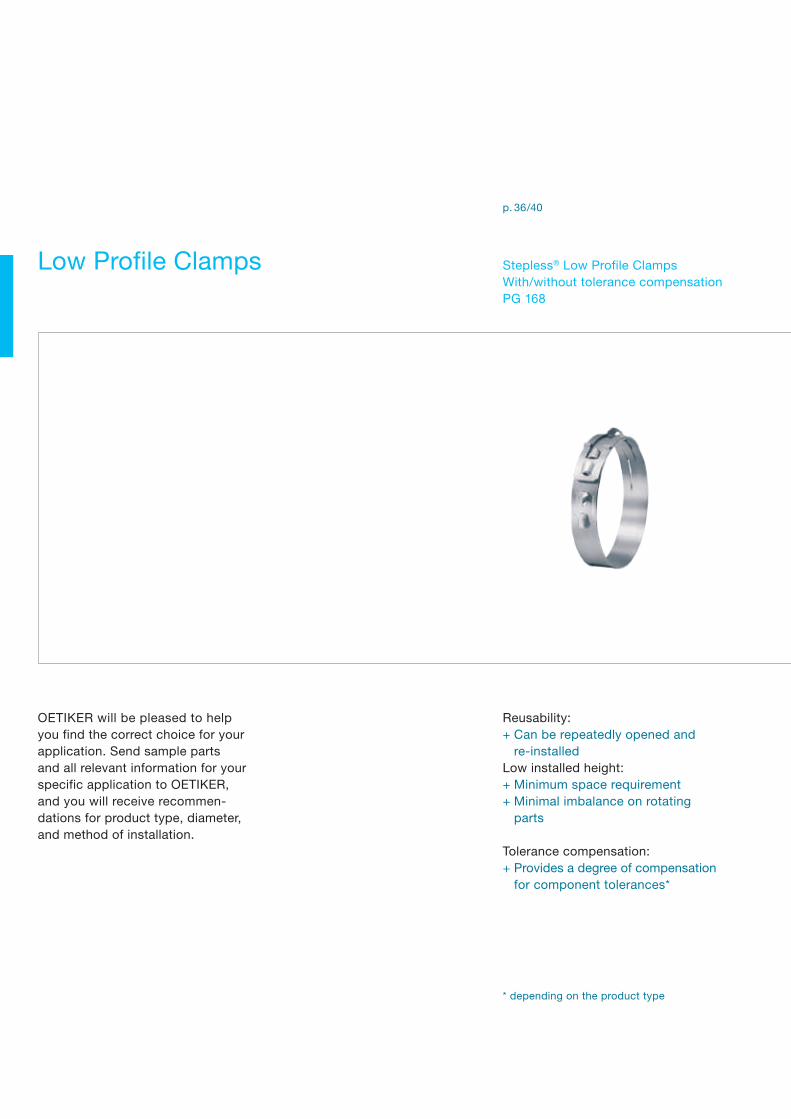
Reusability:+ Can be repeatedly opened and re-installedLow installed height:+ Minimum space requirement+ Minimal imbalance on rotating parts
Tolerance compensation:+ Provides a degree of compensation for component tolerances*
Low Profile Clamps Stepless® Low Profile ClampsWith/without tolerance compensation PG 168
p. 36/40
OETIKER will be pleased to helpyou find the correct choice for your application. Send sample parts and all relevant information for your specific application to OETIKER, and you will receive recommen-dations for product type, diameter, and method of installation.
* depending on the product type

34 / 35
Tolerance compensation convolutes:+ Allow for variations in component tolerances and temperature variations360° Stepless®:+ Uniform 360° compression or uniform surface pressureNovel tensioning hook design:+ Fast and simple installation+ High radial forces
Compact:+ Lightweight+ Miniature sizesSolid closure:+ Fast and simple installation+ Safe connections for low pressure applications
Low Profile Clamps Overview
Stepless® Low Profile Clamps 192PG 192
Clamps ERPG 194
p. 44 p. 48

Stepless® Low Profile Clamps are produced in several nominal widths and thicknesses. The dimensions of the material used for the standard range are determined taking into account the re-quired radial force, the nature of the application and the need to maintain sealing and/or retaining properties under the specified conditions and environmental exposure. When selecting the clamp diameter, the dimensions of the mating components on which the clamp is to be installed must be accurately established to enable effective clamping performance. The durometer hardness of the soft material and the desired compression are important factors when calculating the appropriate clamp diameter.
Tensioning hook and tunnelThe tensioning hook and tunnel have been developed to with-stand a maximum closing force of 2000 N. With the use of an OETIKER installation tool, the clamp is reduced in diameter until the interlock position is achieved. The diameter reduction of the clamp is proportional to the closing travel. The theoretical maximum reduction in diameter is given by the formula:
Low Profile Clamps Stepless® Low Profile Clamps Product Group 168
Stepless® Low Profile ClampsProduct Group 168
Material168 Stainless steel material No. 1.4301 or UNS S30400Alternative materials available on request.
SeriesNominal diameter width x thickness10.5 – 19.0 mm 9.0 x 0.5 mm19.5 – 110.0 mm 7.0 x 0.6 mm25.0 – 110.0 mm 9.0 x 0.6 mm60.0 – 120.5 mm 10.0 x 0.6 mm
Some sizes are only available if an appropriate minimum quantity is ordered.
Reusability: can be repeatedly opened and re-installed360° Stepless®: uniform 360° compression or uniform surface pressureLow installed height: minimum space requirement, low imbalance on rotating partsLoad retaining hooks: visual indication that clamp is correctly installedSpecially formed edges: reduced risk of damage to parts being clamped
Max. diameter reduction =closing travel
π
Tongue-in-groove design
Load retaining hooks
Tensioning hook and tunnel
The data in this catalogue are based on many years experience. They are intended for reference, not as design specifications.

36 / 37Low Profile Clamps Stepless® Low Profile Clamps Product Group 168
Rotation diameterThe rotation diameter (RD) of an assembled clamp can be critical design information for applications that rotate in close proximity to adjacent components. The following list gives rotation diameters for various band sizes and product designs:
RD for 905RWV = inside diameter +7.2 mmRD for 706R = inside diameter +6.0 mmRD for 906R = inside diameter +6.0 mmRD for 1006R = inside diameter +6.3 mm
ReuseabilityOETIKER Stepless® Low Profile Clamps are reusable. They can be repeatedly opened and reinstalled – for example in the automotive industry at maintenance and service intervals. They can be installed both axially and radially.
Note on orderingIn contrast to ear clamps, Stepless® Low Profile Clamps are identified with the nominal closed diameter, e.g. 195 for a closed and installed diameter of 19.5 mm.
Material dimensions Manual pincer* Recommended pneumatic pincer** 9 x 0.5 mm 14100030 HO 3000 7 x 0.6 mm 14100030 HO 3000 9 x 0.6 mm 14100030 HO 300010 x 0.6 mm 14100030 HO 3000
** 14100030 Manual pincer for Stepless® Low Profile Clamps 7 mm and 10 mm wide** With appropriate pincer head
Closing travel
RD
Assembly RecommendationsUsing a hand tool, or a pneumatic tool specifically designed for high volume production, locate the jaw tips in the tensioning hook and tunnel.
Activating the pneumatic tool, or closing the hand tool, simulta-neously draws the two features together, reducing the inside diameter of the clamp. To maintain this reduced diameter, the apertures are depressed over the load retaining hooks and the applied load exerted by the tool is released, so that the hooks engage in the appropriate apertures.
The Stepless® Low Profile Clamp provides a constant, accurate,inside diameter after installation, but, unlike Stepless® Ear Clamps PG 167, will not compensate for variations in component tolerance or accommodate the effects of thermal expansion.
The sealing pressure beneath the clamp is dependent on the compression factor established when determining the appropriate clamp diameter and the resistance to thermal “set” of the soft material.
Complete process monitoring, including 100% documentation is available using the Electronically Controlled pneumatic power tool OETIKER ELK 01.
Low Profile Clamps Stepless® Low Profile Clamps Product Group 168
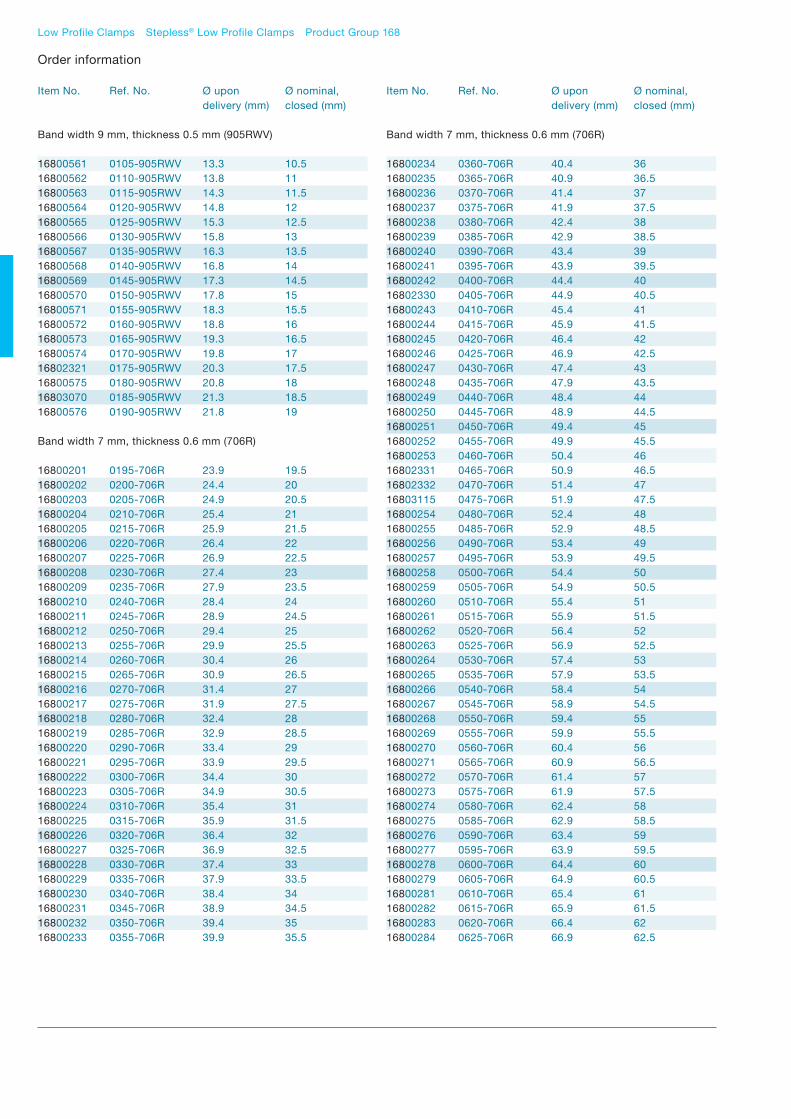
Order information
Item No. Ref. No. Ø upon Ø nominal, delivery (mm) closed (mm)
Band width 9 mm, thickness 0.5 mm (905RWV)
16800561 0105-905RWV 13.3 10.516800562 0110-905RWV 13.8 1116800563 0115-905RWV 14.3 11.516800564 0120-905RWV 14.8 1216800565 0125-905RWV 15.3 12.516800566 0130-905RWV 15.8 1316800567 0135-905RWV 16.3 13.516800568 0140-905RWV 16.8 1416800569 0145-905RWV 17.3 14.516800570 0150-905RWV 17.8 1516800571 0155-905RWV 18.3 15.516800572 0160-905RWV 18.8 1616800573 0165-905RWV 19.3 16.516800574 0170-905RWV 19.8 1716802321 0175-905RWV 20.3 17.516800575 0180-905RWV 20.8 1816803070 0185-905RWV 21.3 18.516800576 0190-905RWV 21.8 19
Band width 7 mm, thickness 0.6 mm (706R)
16800201 0195-706R 23.9 19.516800202 0200-706R 24.4 2016800203 0205-706R 24.9 20.516800204 0210-706R 25.4 2116800205 0215-706R 25.9 21.516800206 0220-706R 26.4 2216800207 0225-706R 26.9 22.516800208 0230-706R 27.4 2316800209 0235-706R 27.9 23.516800210 0240-706R 28.4 2416800211 0245-706R 28.9 24.516800212 0250-706R 29.4 2516800213 0255-706R 29.9 25.516800214 0260-706R 30.4 2616800215 0265-706R 30.9 26.516800216 0270-706R 31.4 2716800217 0275-706R 31.9 27.516800218 0280-706R 32.4 2816800219 0285-706R 32.9 28.516800220 0290-706R 33.4 2916800221 0295-706R 33.9 29.516800222 0300-706R 34.4 3016800223 0305-706R 34.9 30.516800224 0310-706R 35.4 3116800225 0315-706R 35.9 31.516800226 0320-706R 36.4 3216800227 0325-706R 36.9 32.516800228 0330-706R 37.4 3316800229 0335-706R 37.9 33.516800230 0340-706R 38.4 3416800231 0345-706R 38.9 34.516800232 0350-706R 39.4 3516800233 0355-706R 39.9 35.5
Item No. Ref. No. Ø upon Ø nominal, delivery (mm) closed (mm)
Band width 7 mm, thickness 0.6 mm (706R)
16800234 0360-706R 40.4 3616800235 0365-706R 40.9 36.516800236 0370-706R 41.4 3716800237 0375-706R 41.9 37.516800238 0380-706R 42.4 3816800239 0385-706R 42.9 38.516800240 0390-706R 43.4 3916800241 0395-706R 43.9 39.516800242 0400-706R 44.4 4016802330 0405-706R 44.9 40.516800243 0410-706R 45.4 4116800244 0415-706R 45.9 41.516800245 0420-706R 46.4 4216800246 0425-706R 46.9 42.516800247 0430-706R 47.4 4316800248 0435-706R 47.9 43.516800249 0440-706R 48.4 4416800250 0445-706R 48.9 44.516800251 0450-706R 49.4 4516800252 0455-706R 49.9 45.516800253 0460-706R 50.4 4616802331 0465-706R 50.9 46.516802332 0470-706R 51.4 4716803115 0475-706R 51.9 47.516800254 0480-706R 52.4 4816800255 0485-706R 52.9 48.516800256 0490-706R 53.4 4916800257 0495-706R 53.9 49.516800258 0500-706R 54.4 5016800259 0505-706R 54.9 50.516800260 0510-706R 55.4 5116800261 0515-706R 55.9 51.516800262 0520-706R 56.4 5216800263 0525-706R 56.9 52.516800264 0530-706R 57.4 5316800265 0535-706R 57.9 53.516800266 0540-706R 58.4 5416800267 0545-706R 58.9 54.516800268 0550-706R 59.4 5516800269 0555-706R 59.9 55.516800270 0560-706R 60.4 5616800271 0565-706R 60.9 56.516800272 0570-706R 61.4 5716800273 0575-706R 61.9 57.516800274 0580-706R 62.4 5816800275 0585-706R 62.9 58.516800276 0590-706R 63.4 5916800277 0595-706R 63.9 59.516800278 0600-706R 64.4 6016800279 0605-706R 64.9 60.516800281 0610-706R 65.4 6116800282 0615-706R 65.9 61.516800283 0620-706R 66.4 6216800284 0625-706R 66.9 62.5

38 / 39Low Profile Clamps Stepless® Low Profile Clamps Product Group 168
Order information
Item No. Ref. No. Ø upon Ø nominal, delivery (mm) closed (mm)
Band width 7 mm, thickness 0.6 mm (706R)
16800339 0900-706R 94.4 9016800340 0905-706R 94.9 90.516800341 0910-706R 95.4 9116800342 0915-706R 95.9 91.516800343 0920-706R 96.4 9216800344 0925-706R 96.9 92.516800345 0930-706R 97.4 9316800346 0935-706R 97.9 93.516800347 0940-706R 98.4 9416800348 0945-706R 98.9 94.516800349 0950-706R 99.4 9516800350 0955-706R 99.9 95.516800351 0960-706R 100.4 9616800352 0965-706R 100.9 96.516800353 0970-706R 101.4 9716800354 0975-706R 101.9 97.516800355 0980-706R 102.4 9816800356 0985-706R 102.9 98.516800357 0990-706R 103.4 9916800358 0995-706R 103.9 99.516800359 1000-706R 104.4 10016800360 1005-706R 104.9 100.516800361 1010-706R 105.4 10116800362 1015-706R 105.9 101.516800363 1020-706R 106.4 10216800364 1025-706R 106.9 102.516800365 1030-706R 107.4 10316800366 1035-706R 107.9 103.516800367 1040-706R 108.4 10416800368 1045-706R 108.9 104.516800369 1050-706R 109.4 10516800370 1055-706R 109.9 105.516800371 1060-706R 110.4 10616800372 1065-706R 110.9 106.516800373 1070-706R 111.4 10716800374 1075-706R 111.9 107.516800375 1080-706R 112.4 10816800376 1085-706R 112.9 108.516800377 1090-706R 113.4 10916800378 1095-706R 113.9 109.516800379 1100-706R 114.4 110
Band width 9 mm, thickness 0.6 mm (906R)
In the diameter range 25 mm to 110 mm, these clamps areavailable in 0.5 mm steps on request.
Band width 10 mm, thickness 0.6 mm (1006R)
In the diameter range 60 mm to 120.5 mm, these clamps areavailable in 0.5 mm steps on request.
Item No. Ref. No. Ø upon Ø nominal, delivery (mm) closed (mm)
Band width 7 mm, thickness 0.6 mm (706R)
16800285 0630-706R 67.4 6316800286 0635-706R 67.9 63.516800287 0640-706R 68.4 6416800288 0645-706R 68.9 64.516800289 0650-706R 69.4 6516800290 0655-706R 69.9 65.516800291 0660-706R 70.4 6616800292 0665-706R 70.9 66.516800293 0670-706R 71.4 6716800294 0675-706R 71.9 67.516800295 0680-706R 72.4 6816800296 0685-706R 72.9 68.516800297 0690-706R 73.4 6916800298 0695-706R 73.9 69.516800299 0700-706R 74.4 7016800300 0705-706R 74.9 70.516800301 0710-706R 75.4 7116800302 0715-706R 75.9 71.516800303 0720-706R 76.4 7216800304 0725-706R 76.9 72.516800305 0730-706R 77.4 7316800306 0735-706R 77.9 73.516800307 0740-706R 78.4 7416800308 0745-706R 78.9 74.516800309 0750-706R 79.4 7516800310 0755-706R 79.9 75.516800311 0760-706R 80.4 7616800312 0765-706R 80.9 76.516800313 0770-706R 81.4 7716800314 0775-706R 81.9 77.516800315 0780-706R 82.4 7816800316 0785-706R 82.9 78.516800317 0790-706R 83.4 7916800318 0795-706R 83.9 79.516800319 0800-706R 84.4 8016800320 0805-706R 84.9 80.516800321 0810-706R 85.4 8116800322 0815-706R 85.9 81.516800323 0820-706R 86.4 8216800324 0825-706R 86.9 82.516800325 0830-706R 87.4 8316800326 0835-706R 87.9 83.516800327 0840-706R 88.4 8416800328 0845-706R 88.9 84.516800329 0850-706R 89.4 8516800330 0855-706R 89.9 85.516800331 0860-706R 90.4 8616800332 0865-706R 90.9 86.516800333 0870-706R 91.4 8716800334 0875-706R 91.9 87.516800335 0880-706R 92.4 8816800336 0885-706R 92.9 88.516800337 0890-706R 93.4 8916800338 0895-706R 93.9 89.5
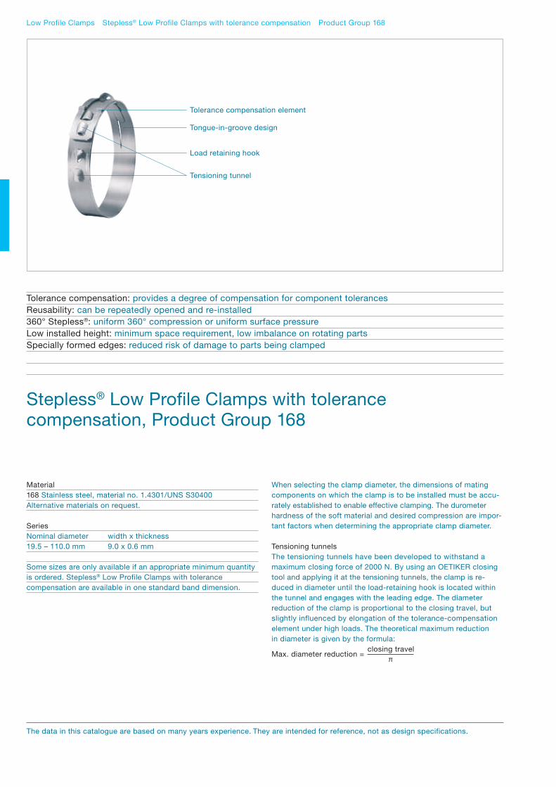
Low Profile Clamps Stepless® Low Profile Clamps with tolerance compensation Product Group 168
Stepless® Low Profile Clamps with tolerancecompensation, Product Group 168
When selecting the clamp diameter, the dimensions of matingcomponents on which the clamp is to be installed must be accu-rately established to enable effective clamping. The durometer hardness of the soft material and desired compression are impor-tant factors when determining the appropriate clamp diameter.
Tensioning tunnelsThe tensioning tunnels have been developed to withstand a maximum closing force of 2000 N. By using an OETIKER closing tool and applying it at the tensioning tunnels, the clamp is re-duced in diameter until the load-retaining hook is located within the tunnel and engages with the leading edge. The diameter reduction of the clamp is proportional to the closing travel, but slightly influenced by elongation of the tolerance-compensation element under high loads. The theoretical maximum reduction in diameter is given by the formula:
Material168 Stainless steel, material no. 1.4301/UNS S30400Alternative materials on request.
SeriesNominal diameter width x thickness19.5 – 110.0 mm 9.0 x 0.6 mm
Some sizes are only available if an appropriate minimum quantity is ordered. Stepless® Low Profile Clamps with tolerance compensation are available in one standard band dimension.
Tolerance compensation: provides a degree of compensation for component tolerancesReusability: can be repeatedly opened and re-installed360° Stepless®: uniform 360° compression or uniform surface pressureLow installed height: minimum space requirement, low imbalance on rotating partsSpecially formed edges: reduced risk of damage to parts being clamped
Tongue-in-groove design
Load retaining hook
Tensioning tunnel
Tolerance compensation element
The data in this catalogue are based on many years experience. They are intended for reference, not as design specifications.
Max. diameter reduction =closing travel
π

40 / 41Low Profile Clamps Stepless® Low Profile Clamps with tolerance compensation Product Group 168
Tolerance compensationThe tolerance-compensating elements come into effect when the nominal diameter of the closed clamp cannot be achieved due to adjacent components being at the upper levels of the tolerance range. When parts being clamped have high durometer hardness values, the compensating element can be fully elon-gated providing the closed position is still achievable.
For optimum performance, a clamp diameter should be selectedbased on the theoretical lower tolerance limits of the components. Then, when the larger dimensional assembly is encountered, the tolerance compensation element is elongated to absorb the increased diameter and allow the load-retaining hook to engage in the tensioning tunnel. The application configuration, the physi-cal properties of the materials being sealed and the required retention, are all critical factors when determining the overall functionality of the connection
Assembly RecommendationsThese clamps can be closed manually using a specially devel-oped hand tool, or a pneumatic pincer when large quantities are to be installed. To close the clamp, the tips of the pincer jaws must be inserted in the tensioning tunnel at the end of the overlap and in the tunnel next to the load-retaining hook. Operation of the closing tool reduces the diameter of the clamp to the position at which engagement of the closing hook occurs.
The design of Stepless® Low Profile Clamps with tolerance com-pensation is such that the inner contour of the tensioning tunnel on the end of the overlap, automatically engages with the load retaining hook when the correct position is achieved. In contrast to Stepless® low-profile clamps without tolerance compensation, they have the ability to accommodate minor variations in compo-nent tolerances during assembly and absorb diameter changes due to thermal expansion and contraction within the range of the compensating element.
As with other types of clamp, the sealing pressure beneath a clamp is a factor of the diameters and materials of the components under compression. The sealing properties of these clamps de-pends significantly on the opposing forces generated in the soft material of parts being secured, and the pre-loading of the tolerance-compensation element.
Material dimensions Manual pincer* Recommended pneumatic pincer** 9 x 0.6 mm 14100109 HO 3000
** 14100109 Manual pincer for Stepless® Low Profile Clamps with tolerance compensation** With appropriate pincer head
Closing travel
Complete process monitoring, including 100% documentation is available using the Electronically Controlled Pneumatic Power Tool OETIKER ELK 01.
Rotation diameterThe Stepless® Low Profile Clamp with tolerance compensation has a low radial height, and was specifically developed for applications where space is restricted, while taking into account the need to accommodate the tolerances of parts being connected.
ReusabilityOETIKER Stepless® Low Profile Clamps with tolerance compen-sation are reusable to a limited extent. They can be repeatedly opened and reinstalled – for example in the automotive industry at maintenance and service intervals. They can be installed both axially and radially. To open a clamp, the pincer must be fitted to the two tunnels (1) and squeezed. The applied force has the effect of slightly reducing the diameter of the clamp, enabling the hook to disengage from the tensioning tunnel (2) on the over-lapping end.
Note on orderingIn contrast to ear clamps, Stepless® Low Profile Clamps are identified with the nominal closed diameter, e.g. 195 for a closed and installed diameter of 19.5 mm.
2 1 1
RD
RD for 906RT8 = inside diameter +7.4 mm

Low Profile Clamps Stepless® Low Profile Clamps with tolerance compensation Product Group 168
Item No. Ref. No. Ø upon Ø nominal, delivery (mm) closed (mm)
Band width 9 mm, thickness 0.6 mm (906RT8)
16802113 0195-906RT8 22 19.516802114 0200-906RT8 22.5 2016802115 0205-906RT8 23 20.516802116 0210-906RT8 23.5 2116802117 0215-906RT8 24 21.516802118 0220-906RT8 24.5 2216802119 0225-906RT8 25 22.516802120 0230-906RT8 25.5 2316802121 0235-906RT8 26 23.516802122 0240-906RT8 26.5 2416802123 0245-906RT8 27 24.516802124 0250-906RT8 27.5 2516802125 0255-906RT8 28 25.516802126 0260-906RT8 28.5 2616802127 0265-906RT8 29 26.516802128 0270-906RT8 29.5 2716802129 0275-906RT8 30 27.516802130 0280-906RT8 30.5 2816802131 0285-906RT8 31 28.516802132 0290-906RT8 31.5 2916802133 0295-906RT8 32 29.516802134 0300-906RT8 32.5 3016802135 0305-906RT8 33 30.516802136 0310-906RT8 33.5 3116802137 0315-906RT8 34 31.516802138 0320-906RT8 34.5 3216802139 0325-906RT8 35 32.516802140 0330-906RT8 35.5 3316802141 0335-906RT8 36 33.516802142 0340-906RT8 36.5 3416802143 0345-906RT8 37 34.516802144 0350-906RT8 37.5 3516802145 0355-906RT8 38 35.516802146 0360-906RT8 38.5 3616802147 0365-906RT8 39 36.516802148 0370-906RT8 39.5 3716802149 0375-906RT8 40 37.516802150 0380-906RT8 40.5 3816802151 0385-906RT8 41 38.516802152 0390-906RT8 41.5 3916802153 0395-906RT8 42 39.516802154 0400-906RT8 42.5 4016802155 0405-906RT8 43 40.516802156 0410-906RT8 43.5 4116802157 0415-906RT8 44 41.516802158 0420-906RT8 44.5 4216802159 0425-906RT8 45 42.516802160 0430-906RT8 45.5 4316802161 0435-906RT8 46 43.516802162 0440-906RT8 46.5 4416802163 0445-906RT8 47 44.516802164 0450-906RT8 47.5 4516802165 0455-906RT8 48 45.516802166 0460-906RT8 48.5 4616802167 0465-906RT8 49 46.516802168 0470-906RT8 49.5 4716802169 0475-906RT8 50 47.5
Order information
Item No. Ref. No. Ø upon Ø nominal, delivery (mm) closed (mm)
Band width 9 mm, thickness 0.6 mm (906RT8)
16802170 0480-906RT8 50.5 4816802171 0485-906RT8 51 48.516802172 0490-906RT8 51.5 4916802173 0495-906RT8 52 49.516802174 0500-906RT8 52.5 5016802175 0505-906RT8 53 50.516802176 0510-906RT8 53.5 5116802177 0515-906RT8 54 51.516802178 0520-906RT8 54.5 5216802179 0525-906RT8 55 52.516802180 0530-906RT8 55.5 5316802181 0535-906RT8 56 53.516802182 0540-906RT8 56.5 5416802183 0545-906RT8 57 54.516802184 0550-906RT8 57.5 5516802185 0555-906RT8 58 55.516802186 0560-906RT8 58.5 5616802187 0565-906RT8 59 56.516802188 0570-906RT8 59.5 5716802189 0575-906RT8 60 57.516802190 0580-906RT8 60.5 5816802191 0585-906RT8 61 58.516802192 0590-906RT8 61.5 5916801880 0595-906RT8 62 59.516802193 0600-906RT8 62.5 6016802194 0605-906RT8 63 60.516802195 0610-906RT8 63.5 6116802196 0615-906RT8 64 61.516802197 0620-906RT8 64.5 6216802198 0625-906RT8 65 62.516802199 0630-906RT8 65.5 6316802200 0635-906RT8 66 63.516802201 0640-906RT8 66.5 6416802202 0645-906RT8 67 64.516801881 0650-906RT8 67.5 6516802203 0655-906RT8 68 65.516802204 0660-906RT8 68.5 6616802205 0665-906RT8 69 66.516802206 0670-906RT8 69.5 6716802207 0675-906RT8 70 67.516802208 0680-906RT8 70.5 6816802209 0685-906RT8 71 68.516802210 0690-906RT8 71.5 6916802211 0695-906RT8 72 69.516802212 0700-906RT8 72.5 7016802213 0705-906RT8 73 70.516802214 0710-906RT8 73.5 7116802215 0715-906RT8 74 71.516802216 0720-906RT8 74.5 7216802217 0725-906RT8 75 72.516802218 0730-906RT8 75.5 7316802219 0735-906RT8 76 73.516802220 0740-906RT8 76.5 7416802221 0745-906RT8 77 74.516802222 0750-906RT8 77.5 7516802223 0755-906RT8 78 75.516802224 0760-906RT8 78.5 76

42 / 43Low Profile Clamps Stepless® Low Profile Clamps with tolerance compensation Product Group 168
Item No. Ref. No. Ø upon Ø nominal, delivery (mm) closed (mm)
Band width 9 mm, thickness 0.6 mm (906RT8)
16802225 0765-906RT8 79 76.516802226 0770-906RT8 79.5 7716802227 0775-906RT8 80 77.516802228 0780-906RT8 80.5 7816802229 0785-906RT8 81 78.516802230 0790-906RT8 81.5 7916802231 0795-906RT8 82 79.516802232 0800-906RT8 82.5 8016802233 0805-906RT8 83 80.516802234 0810-906RT8 83.5 8116802235 0815-906RT8 84 81.516802236 0820-906RT8 84.5 8216802237 0825-906RT8 85 82.516802238 0830-906RT8 85.5 8316802239 0835-906RT8 86 83.516802240 0840-906RT8 86.5 8416802241 0845-906RT8 87 84.516802242 0850-906RT8 87.5 8516802243 0855-906RT8 88 85.516802244 0860-906RT8 88.5 8616802112 0865-906RT8 89 86.516802245 0870-906RT8 89.5 8716802246 0875-906RT8 90 87.516802247 0880-906RT8 90.5 8816802248 0885-906RT8 91 88.516802249 0890-906RT8 91.5 8916802250 0895-906RT8 92 89.516802251 0900-906RT8 92.5 9016802252 0905-906RT8 93 90.516802253 0910-906RT8 93.5 9116802254 0915-906RT8 94 91.516802255 0920-906RT8 94.5 9216802256 0925-906RT8 95 92.516802257 0930-906RT8 95.5 9316802258 0935-906RT8 96 93.516802259 0940-906RT8 96.5 9416802260 0945-906RT8 97 94.516802261 0950-906RT8 97.5 9516802262 0955-906RT8 98 95.516802263 0960-906RT8 98.5 9616802264 0965-906RT8 99 96.516802265 0970-906RT8 99.5 9716802266 0975-906RT8 100 97.516802267 0980-906RT8 100.5 9816802268 0985-906RT8 101 98.516802269 0990-906RT8 101.5 9916802270 0995-906RT8 102 99.516802271 1000-906RT8 102.5 10016802412 1005-906RT8 103 100.516802404 1010-906RT8 103.5 10116802418 1015-906RT8 104 101.516802419 1020-906RT8 104.5 10216803030 1025-906RT8 105 102.516803031 1030-906RT8 105.5 10316803032 1035-906RT8 106 103.516803033 1040-906RT8 106.5 10416803034 1045-906RT8 107 104.5
Order information
Item No. Ref. No. Ø upon Ø nominal, delivery (mm) closed (mm)
Band width 9 mm, thickness 0.6 mm (906RT8)
16803035 1050-906RT8 107.5 10516803036 1055-906RT8 108 105.516803037 1060-906RT8 108.5 10616803038 1065-906RT8 109 106.516802617 1070-906RT8 109.5 10716803039 1075-906RT8 110 107.516803040 1080-906RT8 110.5 10816803041 1085-906RT8 111 108.516803042 1090-906RT8 111.5 10916803043 1095-906RT8 112 109.516803044 1100-906RT8 112.5 110
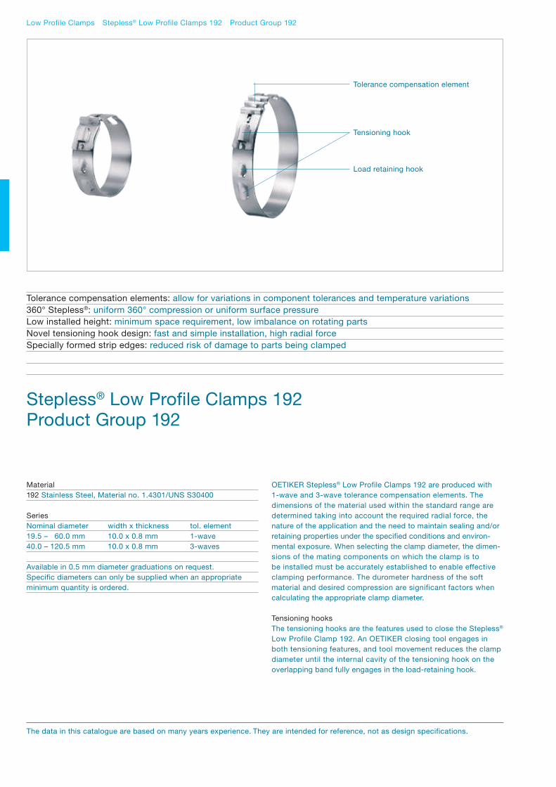
OETIKER Stepless® Low Profile Clamps 192 are produced with 1-wave and 3-wave tolerance compensation elements. The dimensions of the material used within the standard range are determined taking into account the required radial force, the nature of the application and the need to maintain sealing and/or retaining properties under the specified conditions and environ-mental exposure. When selecting the clamp diameter, the dimen-sions of the mating components on which the clamp is to be installed must be accurately established to enable effective clamping performance. The durometer hardness of the soft material and desired compression are significant factors when calculating the appropriate clamp diameter.
Tensioning hooksThe tensioning hooks are the features used to close the Stepless® Low Profile Clamp 192. An OETIKER closing tool engages in both tensioning features, and tool movement reduces the clamp diameter until the internal cavity of the tensioning hook on the overlapping band fully engages in the load-retaining hook.
Low Profile Clamps Stepless® Low Profile Clamps 192 Product Group 192
Stepless® Low Profile Clamps 192Product Group 192
Material192 Stainless Steel, Material no. 1.4301/UNS S30400
SeriesNominal diameter width x thickness tol. element19.5 – 60.0 mm 10.0 x 0.8 mm 1-wave40.0 – 120.5 mm 10.0 x 0.8 mm 3-waves
Available in 0.5 mm diameter graduations on request. Specific diameters can only be supplied when an appropriate minimum quantity is ordered.
Tolerance compensation elements: allow for variations in component tolerances and temperature variations360° Stepless®: uniform 360° compression or uniform surface pressureLow installed height: minimum space requirement, low imbalance on rotating partsNovel tensioning hook design: fast and simple installation, high radial forceSpecially formed strip edges: reduced risk of damage to parts being clamped
Load retaining hook
Tensioning hook
Tolerance compensation element
The data in this catalogue are based on many years experience. They are intended for reference, not as design specifications.

44 / 45Low Profile Clamps Stepless® Low Profile Clamps 192 Product Group 192
The diameter reduction of the clamp is substantially proportional to the closing travel, but subject to slight variations, depending on the degree to which tolerance compensation is required and the required radial force. The theoretical maximum reduction in diameter is given by the formula:
Tolerance compensationThe tolerance compensation waves are activated when the compressed diameter of the application is greater than the nomi-nal diameter of the clamp. When the resistance against the clamp exceeds the strength of the formed convolutes, elongation occurs to enable successful engagement of the tensioning and retaining hooks.
The flexible effect of the convolutes has the potential to accom-modate diameter changes due to the effects of temperature changes and vibration.
As a rule, the nominal diameter of an OETIKER Stepless® Low Profile Clamp 192 should be selected to enable the optimum hose or seal compression at the minimum assembly diameter. In the event of a maximum assembly installation, the convolutes must be capable of elongating to absorb the diameter increase while maintaining the ability to achieve the interlock engagement, taking into account the maximum permitted pincer force and the amount of elongation the convolutes can withstand.
The capability of the tolerance-compensation element, the proper-ties and dimensional tolerance of the materials being joined all directly affect the overall functionality of the connection.
Assembly RecommendationsThese clamps can be installed using manual pincers especially developed for this clamp design or, alternatively, pneumatic pincers for high volume installations. To close a clamp, the pincer jaws must be engaged within both tensioning hooks. By operating the pneumatic tool or closing the manual pincer, the simultaneous movement of the two tensioning hooks reduces the diameter of the Stepless® Low Profile Clamp 192 until the effective closed diameter is achieved. The geometry of the Stepless® Low Profile Clamp 192 is such that, on reaching this position, the internal contour of the tensioning hook on the overlapping end of the clamp engages automatically in the load retaining hook.
The surface pressure generated depends on the selection criteria, especially the diameter and materials of the parts being clamped. Sealing performance is derived mainly from the restoring force of the compressed elastic material combined with tension from the tolerance-compensation elements.
Complete process monitoring, including 100% documentation is available using the “Electronically Controlled Pneumatic Power Tool OETIKER ELK 01”.
Rotation diameterThe rotation diameter (RD) of an assembled clamp can be critical design information for applications that rotate in close proximity to adjacent components.
Accurate Information regarding rotation diameter can be provided on request.
Note on orderingIn contrast to ear clamps, Stepless® Low Profile Clamps are identified with the nominal closed diameter, e.g. 195 for a closed and installed diameter of 19.5 mm.
Material dimensions Manual pincer* Recommended pneumatic pincer** 10.0 x 0.8 mm 14100134 HO 5000 EL/HO 7000 EL
** 14100134 Manual pincer for Stepless® Low Profile Clamps 192.** With appropriate pincer head and closing force setting. Please provide us with appropriate sample parts and comprehensive information about the application.
(14.5)
Closing travel Closing travel*
(9.4)
RD
RD
* Optionally available with enlarged as-supplied diameter (greater closing travel)
Max. diameter reduction =closing travel
π

Low Profile Clamps Stepless® Low Profile Clamps 192 Product Group 192
Item No. Ø upon Ø nominal, delivery (mm) closed (mm) *
Tolerance compensation element 1-waveBand width 10 mm, thickness 0.8 mm
19200686 22.5 19.519200684 23 20 19200685 23.5 20.519200688 24 2119200733 24.5 21.519200734 25 2219200244 25.5 22.519200245 26 2319200255 26.5 23.519200263 27 2419200368 27.5 24.519200369 28 2519200370 28.5 25.519200371 29 2619200372 29.5 26.519200253 30 2719200322 30.5 27.519200373 31 2819200374 31.5 28.519200268 32 2919200375 32.5 29.519200376 33 3019200377 33.5 30.519200378 34 3119200379 34.5 31.519200380 35 3219200381 35.5 32.519200333 36 3319200335 36.5 33.519200382 37 3419200383 37.5 34.519200332 38 3519200384 38.5 35.519200385 39 3619200386 39.5 36.519200358 40 3719200387 40.5 37.519200388 41 3819200389 41.5 38.519200390 42 3919200391 42.5 39.519200392 43 4019200393 43.5 40.519200394 44 4119200395 44.5 41.519200396 45 4219200397 45.5 42.519200398 46 4319200399 46.5 43.5
Order information
Item No. Ø upon Ø nominal, delivery (mm) closed (mm) *
Tolerance compensation element 1-waveBand width 10 mm, thickness 0.8 mm
19200400 47 4419200401 47.5 44.519200402 48 4519200403 48.5 45.519200404 49 4619200405 49.5 46.519200406 50 4719200407 50.5 47.519200408 51 4819200409 51.5 48.519200410 52 4919200411 52.5 49.519200412 53 5019200413 53.5 50.519200414 54 5119200415 54.5 51.519200416 55 5219200417 55.5 52.519200418 56 5319200419 56.5 53.519200420 57 5419200421 57.5 54.519200422 58 5519200423 58.5 55.519200424 59 5619200425 59.5 56.519200426 60 5719200427 60.5 57.519200428 61 5819200429 61.5 58.519200430 62 5919200431 62.5 59.519200432 63 60
Optionally available with enlarged as supplied diameter (greater closing travel).
Item No. Ø upon Ø nominal, delivery (mm) closed (mm) *
Tolerance compensation element 3-wavesBand width 10 mm, thickness 0.8 mm
19200454 44.5 4019200455 45 40.519200350 45.5 4119200352 46 41.519200456 46.5 4219200457 47 42.519200458 47.5 4319200459 48 43.519200460 48.5 4419200461 49 44.519200462 49.5 4519200463 50 45.519200464 50.5 4619200465 51 46.519200466 51.5 4719200467 52 47.519200468 52.5 4819200469 53 48.519200470 53.5 4919200471 54 49.519200472 54.5 5019200473 55 50.519200474 55.5 5119200339 56 51.519200340 56.5 5219200475 57 52.519200476 57.5 5319200477 58 53.519200478 58.5 5419200479 59 54.519200480 59.5 5519200481 60 55.519200482 60.5 5619200483 61 56.519200484 61.5 5719200485 62 57.519200486 62.5 5819200487 63 58.519200488 63.5 5919200489 64 59.519200490 64.5 6019200491 65 60.519200492 65.5 6119200493 66 61.519200494 66.5 6219200495 67 62.519200496 67.5 6319200341 68 63.519200342 68.5 64
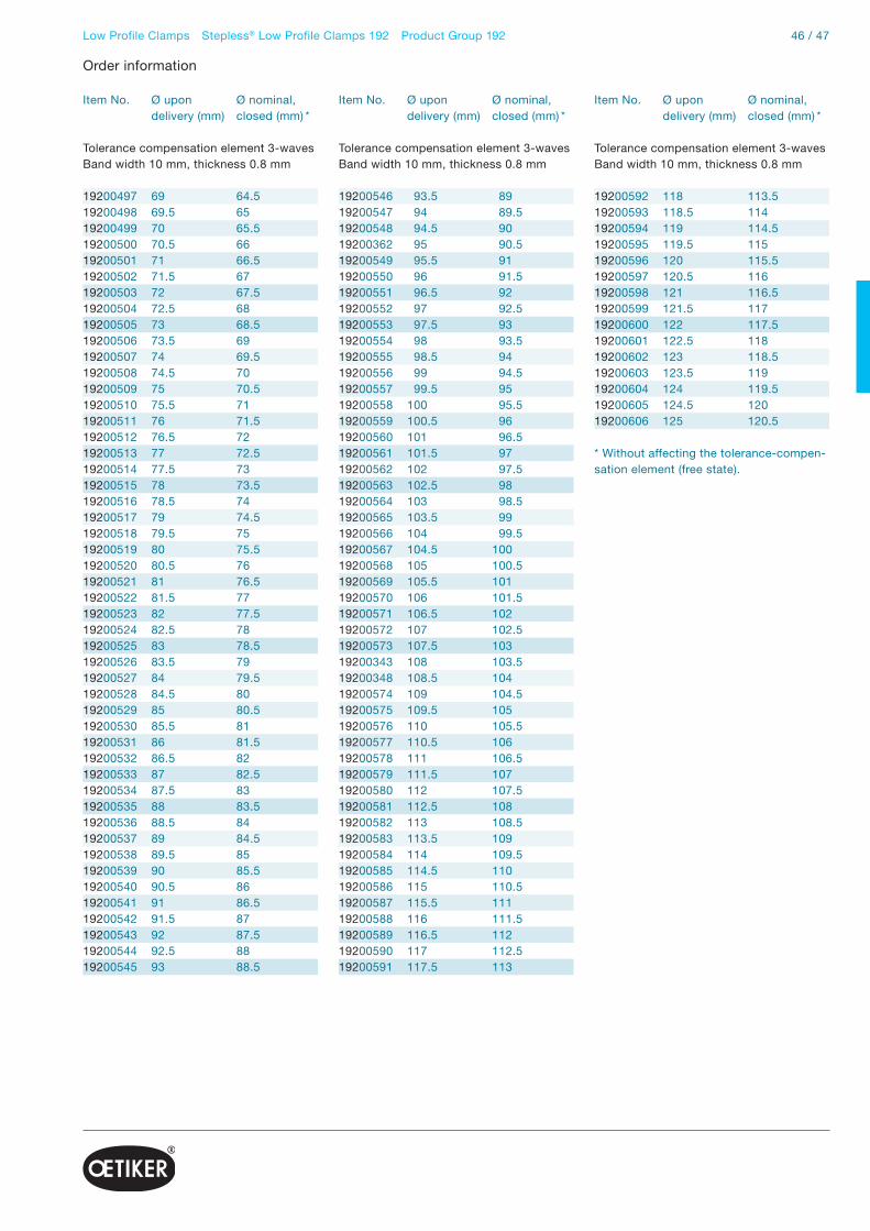
46 / 47Low Profile Clamps Stepless® Low Profile Clamps 192 Product Group 192
Item No. Ø upon Ø nominal, delivery (mm) closed (mm) *
Tolerance compensation element 3-wavesBand width 10 mm, thickness 0.8 mm
19200497 69 64.519200498 69.5 6519200499 70 65.519200500 70.5 6619200501 71 66.519200502 71.5 6719200503 72 67.519200504 72.5 6819200505 73 68.519200506 73.5 6919200507 74 69.519200508 74.5 7019200509 75 70.519200510 75.5 7119200511 76 71.519200512 76.5 7219200513 77 72.519200514 77.5 7319200515 78 73.519200516 78.5 7419200517 79 74.519200518 79.5 7519200519 80 75.519200520 80.5 7619200521 81 76.519200522 81.5 7719200523 82 77.519200524 82.5 7819200525 83 78.519200526 83.5 7919200527 84 79.519200528 84.5 8019200529 85 80.519200530 85.5 8119200531 86 81.519200532 86.5 8219200533 87 82.519200534 87.5 8319200535 88 83.519200536 88.5 8419200537 89 84.519200538 89.5 8519200539 90 85.519200540 90.5 8619200541 91 86.519200542 91.5 8719200543 92 87.519200544 92.5 8819200545 93 88.5
Order information
Item No. Ø upon Ø nominal, delivery (mm) closed (mm) *
Tolerance compensation element 3-wavesBand width 10 mm, thickness 0.8 mm
19200546 93.5 8919200547 94 89.519200548 94.5 9019200362 95 90.519200549 95.5 9119200550 96 91.519200551 96.5 9219200552 97 92.519200553 97.5 9319200554 98 93.519200555 98.5 9419200556 99 94.519200557 99.5 9519200558 100 95.519200559 100.5 9619200560 101 96.519200561 101.5 9719200562 102 97.5 19200563 102.5 9819200564 103 98.519200565 103.5 9919200566 104 99.519200567 104.5 10019200568 105 100.519200569 105.5 10119200570 106 101.519200571 106.5 10219200572 107 102.519200573 107.5 10319200343 108 103.519200348 108.5 10419200574 109 104.519200575 109.5 10519200576 110 105.519200577 110.5 10619200578 111 106.519200579 111.5 10719200580 112 107.519200581 112.5 10819200582 113 108.519200583 113.5 10919200584 114 109.519200585 114.5 11019200586 115 110.519200587 115.5 11119200588 116 111.519200589 116.5 11219200590 117 112.519200591 117.5 113
Item No. Ø upon Ø nominal, delivery (mm) closed (mm) *
Tolerance compensation element 3-wavesBand width 10 mm, thickness 0.8 mm
19200592 118 113.519200593 118.5 11419200594 119 114.519200595 119.5 11519200596 120 115.519200597 120.5 11619200598 121 116.519200599 121.5 11719200600 122 117.519200601 122.5 11819200602 123 118.519200603 123.5 11919200604 124 119.519200605 124.5 12019200606 125 120.5
* Without affecting the tolerance-compen-sation element (free state).
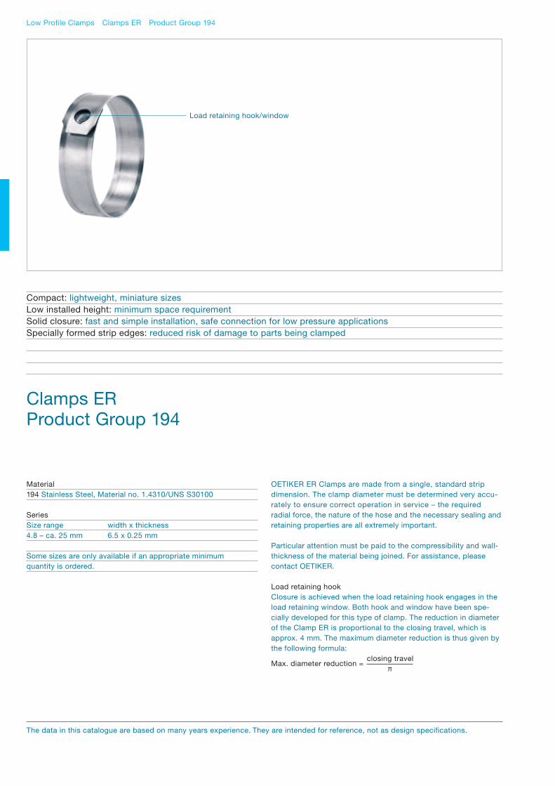
OETIKER ER Clamps are made from a single, standard strip dimension. The clamp diameter must be determined very accu-rately to ensure correct operation in service – the required radial force, the nature of the hose and the necessary sealing and retaining properties are all extremely important.
Particular attention must be paid to the compressibility and wall- thickness of the material being joined. For assistance, pleasecontact OETIKER.
Load retaining hookClosure is achieved when the load retaining hook engages in the load retaining window. Both hook and window have been spe-cially developed for this type of clamp. The reduction in diameter of the Clamp ER is proportional to the closing travel, which is approx. 4 mm. The maximum diameter reduction is thus given by the following formula:
Low Profile Clamps Clamps ER Product Group 194
Clamps ERProduct Group 194
Material194 Stainless Steel, Material no. 1.4310/UNS S30100
SeriesSize range width x thickness4.8 – ca. 25 mm 6.5 x 0.25 mm
Some sizes are only available if an appropriate minimum quantity is ordered.
Compact: lightweight, miniature sizesLow installed height: minimum space requirementSolid closure: fast and simple installation, safe connection for low pressure applicationsSpecially formed strip edges: reduced risk of damage to parts being clamped
Load retaining hook/window
The data in this catalogue are based on many years experience. They are intended for reference, not as design specifications.
Max. diameter reduction =closing travel
π
48 / 49Low Profile Clamps Clamps ER Product Group 194
The very thin material, from which these clamps are made, only0.25 mm, means that after installation there is only a very smallstep where the two ends of the clamp overlap. The effect of this is that the ER Clamps exert almost uniform compression, or surface pressure, on clamped parts.
The result is effective clamping of compressible materials for allmanner of applications. The sealing characteristics of Clamps ERdepend on the resilience provided by the compressed elasticmaterial of the parts joined.
Assembly RecommendationsClamps ER can be closed using a specially-developed manual pincer, or, for large quantities, using a pneumatic pincer. To install a clamp, the diameter is reduced by jaws, which completely surround it, until the load retaining hook engages in the load retaining window in the overlapping end. No specific orientation within the tool is required prior to closure.
Note on orderingOETIKER Clamps ER are identified with the nominal closed diameter, e.g. 6 for a closed diameter of 6 mm.

Choice of engagement positions:+ Clamp can be adjusted to several different nominal diameters360° Stepless®:+ Uniform compression, or uniform surface pressureSelf-tensioning:+ Compensates for thermal cycle diameter changes
Toggle lock with intermediateposition:+ Fast and simple installation+ High tightening torqueVisual overload protection:+ Protection against excessive tightening
Screw Clamps and Universal Clamps Stepless® Screw Clamp
PG 178ALSI Worm Drive ClampsPG 180
p. 52 p. 54
OETIKER will be pleased to helpyou find the correct choice for your application. Send sample parts and all relevant information for your specific application to OETIKER, and you will receive recommen-dations for product type, diameter, and method of installation.

50 / 51
Compact design:+ Minimal space requirement+ Miniature sizesEmbossed band:+ Reduced risk of damage to the part being clamped
Perforated band strip:+ Universally applicable, various diameters and widthsRatchet lock:+ Installation and removal without toolsScrew lock:+ Simple installation, high holding force
Comply with DIN 3017:+ Embossed clamp band+ Large clamping range+ High holding forcesShort housing saddle:+ Uniform force distribution and good sealing
Screw Clamps and Universal Clamps Overview
Universal clampsPG 174
MINI Worm Drive ClampsPG 180
Worm Drive ClampsPG 126 & 177
p. 56 p. 58 p. 62

Screw Clamps and Universal Clamps Stepless® Screw Clamps Product Group 178
Stepless® Screw ClampsProduct Group 178
Material thicknessOETIKER Stepless® Screw Clamps and Self-Tensioning Stepless® Screw Clamps are made from strip material 9 mm wide and 0.6 mm thick. The dimensions of the strip ensure optimum sealing with EPDM rubber and silicone hoses, while taking into account the necessary radial force, the compressibility of the hose, the sealing/retaining properties and the environmental conditions.
InterlockThe closure is a mechanical interlock whose function is to providesecure retention of the round clamp geometry. The interlock can be opened to permit radial installation of the clamp, and at the same time provides a simple way of relocating the interlockfeatures to obtain alternative diameters prior to tightening.
Positions for diameter changesSizes 24–42 mm– 3 different positions– diameter change for each step 1.6 mmSizes 45–55 mm– 3 different positions– diameter change for each step 2.1 mm
Material178 Band, spacer, retaining elements (D-nut):Stainless Steel, Material no. 1.4301/UNS S30400Screw: Stainless Steel, Material no. 1.4319/UNS S30200Spring: 17-7PH (aerospace quality)
SeriesSize range width x thickness18.0 – 255.0 mm 9.0 x 0.6 mm
Some sizes are only available if an appropriate minimum quantity is ordered.
Choice of engagement positions: clamp can be adjusted to several different nominal diametersNarrow Band: concentrated transmission of clamping force, complies with SAE J1508 Type SSPC360° Stepless®: uniform compression, or uniform surface pressure.Specially formed strip edges: reduced risk of damage to the part being clampedSelf-tensioning: compensates for thermal cycle diameter changes
Bridge
Tongue-in-groove design
Interlock with multiple diameter adjustments
Installation aid for largediameters
The data in this catalogue are based on many years experience. They are intended for reference, not as design specifications.
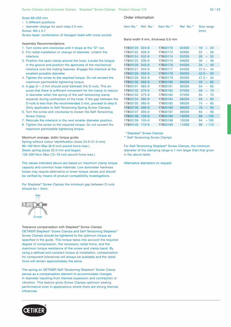
52 / 53
Sizes 60–255 mm– 5 different positions– diameter change for each step 2.0 mmScrew: M4 x 0.7Screw head: combination of hexagon head with cross-socket
Assembly Recommendations1. Turn screw anti-clockwise until it stops at the “D” nut.2. For radial installation or change of diameter, unlatch the
interlock.3. Position the open clamp around the hose. Locate the tongue
in the groove and position the apertures of the mechanical interlock over the mating features. Engage the interlock at the smallest possible diameter.
4. Tighten the screw to the required torque. Do not exceed the maximum permissible tightening torque.
5. A gap of > 3 mm should exist between the D-nuts. This en-sures that there is sufficient movement for the clamp to reduce in diameter when the spring of the self-tensioning clamp expands during contraction of the hose. If the gap between the D-nuts is less than the recommended 3 mm, proceed to step 6. (Only applicable to Self-Tensioning Spring Screw Clamps).
6. Turn the screw anti-clockwise to loosen the Self-Tensioning Screw Clamp.
7. Relocate the interlock in the next smaller diameter position.8. Tighten the screw to the required torque. Do not exceed the
maximum permissible tightening torque.
Maximum average, static torque guide:Spring without colour identification (sizes 24.0–31.0 mm):90–100 Ncm Max (8–9 inch pound-force max.)Green spring (sizes 32.0 mm and larger):135–200 Ncm Max (12–18 inch pound-force max.) The values indicated above are based on maximum clamp torque capacity and common hose materials. Low durometer hardnesshoses may require alternative or lower torque values and should be verified by means of product compatibility investigations.
For Stepless® Screw Clamps the minimum gap between D-nuts should be > 3mm.
Tolerance compensation with Stepless® Screw ClampsOETIKER Stepless® Screw Clamps and Self-Tensioning Stepless® Screw Clamps should be tightened to the optimum torque as specified in the guide. This torque takes into account the required degree of compression, the necessary radial force, and the maximum torque resistance of the screw and clamp band. By using a defined and constant torque at installation, compensation for component tolerances will always be available and the radial force will remain approximately the same.
The spring on OETIKER Self-Tensioning Stepless® Screw Clamp serves as a compensation element to accommodate changes in diameter resulting from thermal expansion and contraction or vibration. This feature gives Screw Clamps optimum sealing performance even in applications where there are strong thermal influences.
Screw Clamps and Universal Clamps Stepless® Screw Clamps Product Group 178
Gap
D-nuts
Order information
Item No.* Ref. No.* Item No.** Ref. No.** Size range (mm)
Band width 9 mm, thickness 0.6 mm
17800120 024-9 17800170 024S9 18 – 2417800122 028-9 17800172 028S9 22 – 2817800124 032-9 17800174 032S9 26 – 3217800125 036-9 17800175 036S9 30 – 3617800126 040-9 17800176 040S9 34 – 4017800127 045-9 17800177 045S9 37.5 – 4517800128 050-9 17800178 050S9 42.5 – 5017800129 055-9 17800179 055S9 47.5 – 5517800130 060-9 17800180 060S9 49 – 6017800131 065-9 17800181 065S9 54 – 6517800132 070-9 17800182 070S9 59 – 7017800133 075-9 17800183 075S9 64 – 7517800134 080-9 17800184 080S9 69 – 8017800135 085-9 17800185 085S9 74 – 8517800136 090-9 17800186 090S9 79 – 9017800137 095-9 17800187 095S9 84 – 9517800138 100-9 17800188 100S9 89 – 10017800139 105-9 17800189 105S9 94 – 10517800140 110-9 17800190 110S9 99 – 110
** Stepless® Screw Clamps** Self-Tensioning Screw Clamps
For Self-Tensioning Stepless® Screw Clamps, the minimum diameter of the clamping range is 1 mm larger than that given in the above table.
Alternative diameters on request.

Screw Clamps and Universal Clamps ALSI Worm Drive Clamps Product Group 180
ALSI Worm Drive ClampsProduct Group 180
Screw Clamp design
Flap lockAfter opening the body, the band can be formed by hand to approximately the clamping diameter. The flap can then be closed, and the clamp tightened by turning the screw. As a result, the screw only has to be turned for the last part of the clamping operation.
Intermediate stopThe flap is secured by an intermediate stop. Even when loosely installed, clamps cannot open on their own accord.
Visual overload protectionThe housing incorporates a web which distorts visibly above a tightening torque of 4–5 Nm (35–44 in-lbs). This visual feature indicates that an ALSI Worm Drive Clamp is optimally tightened and still has an adequate factor of safety to the maximum tightening torque.
Material180 W4 Band and fastener: Stainless Steel,Material no. 1.4301/UNS S30400Screw: Stainless Steel, Material no. 1.4305/UNS S30300
SeriesSize range width x thickness30.0 – 500.0 mm 12.2 x 0.9 mm
Special sizes up to 1000 mm diameter available on request.
Some sizes are only available if an appropriate minimum quantity is ordered.
Toggle lock with intermediate position: fast and simple installation, high tightening torqueVisual overload protection: protects against excessive tighteningHexagon socket screw SW5: fast and safe installationAlternative with wing screw: tool integrated in the clamp
Housing with flap lock and hexagon socket screw SW5
Interlock and visual overload protection
The data in this catalogue are based on many years experience. They are intended for reference, not as design specifications.

54 / 55
ALSI F with wing screwThe ALSI F Worm Drive Clamp with wing screw can be installed entirely without tools. The integral, torsionally-stiff wing provides optimum grip. Except for the wing screw, the installed dimensions are the same as those of the ALSI version.
OETIKER ALSI Universal Clamp BandAvailable in 8 or 12 mm band widths in rolls of 10, 20 or 30 m band length.
Closing element for ALSI Stainless Steel Universal Clamp Band issuitable for both 8 and 12 mm band widths.
Screw Clamps and Universal Clamps ALSI Worm Drive Clamps Product Group 180
Order information
Item No. Description ALSI Universal Clamp BandBand width 8 mm, thickness 0.5 mm
18000211 Closing element for ALSI stainless steel18000213 Universal clamp band, roll 10 m long18000214 Universal clamp band, roll 20 m long18000215 Universal clamp band, roll 30 m long
Item No. Type Clamping range D (mm)
ALSI Screw ClampsBand width 12 mm, thickness 0.9 mm
18000206 ALSI 0 30 – 6018000069 ALSI 40 – 11018000212 ALSI 40 – 16018000025 ALSI 1 50 – 8018000026 ALSI 2 80 – 11018000027 ALSI 3 110 – 14018000028 ALSI 4 140 – 17018000029 ALSI 5 170 – 20018000030 ALSI 6 200 – 23018000031 ALSI 7 230 – 26018000032 ALSI 8 260 – 29018000033 ALSI 9 290 – 32018000034 ALSI 10 320 – 350
Item No. Type Clamping range D (mm)
ALSI F with wing screwBand width 12 mm, thickness 0.9 mm
18000207 ALSI F 0 30 – 6018000136 ALSI F 1 50 – 8018000137 ALSI F 2 80 – 11018000135 ALSI F 3 110 – 14018000168 ALSI F 4 140 – 17018000143 ALSI F 5 170 – 20018000169 ALSI F 6 200 – 23018000174 ALSI F 7 230 – 26018000175 ALSI F 8 260 – 29018000176 ALSI F 9 290 – 32018000177 ALSI F 10 320 – 350
ALSI Worm Drive Clamps are available for a clamping range from 30 mm up to 1000 mm. Up to Size 5, ALSI Worm Drive Clamps are delivered pre-shaped; above Size 6 they are supplied flat.Customer-specific sizes are available on request.
Item No. Description ALSI Universal Clamp BandBand width 12 mm, thickness 0.5 mm
18000211 Closing element for ALSI stainless steel18000216 Universal clamp band, roll 10 m long18000217 Universal clamp band, roll 20 m long18000218 Universal clamp band, roll 30 m long
Assembly RecommendationsFor safe tightening of screw clamps without wing screws, we recommend use of a 5A/F hexagon wrench. The maximum static tightening torque is 6 Nm (53 in-lb).
Installing an ALSI Universal Worm Drive ClampMeasure the circumference to be clamped and cut off the band to that length. Pass the end of the band, from above, through the slit in the closing element, and fold it back at least 40 mm below the band. Pass the second end of the band through the slit in the perforated part of the closing element and fold it back at least 40 mm. Lay the band around the part to be clamped, push the band end with perforation below the flap lock and close.
Tighten the clamp with a 5 A/F hexagon wrench. This system may not be entirely suitable for soft and flexible components.

Screw Clamps and Universal Clamps MINI Worm Drive Clamps Product Group 180
MINI Worm Drive ClampsProduct Group 180
Clamp DesignOETIKER MINI R+S Worm Drive Clamps
Material type MINI R 180W2 Band: Rust-resistant chromium steel, Material no. 1.4016/UNS S43000 Screw and housing: Steel, zinc-plated, blue chromate finish
Material type MINI R+S 180W4 Band and fastener: Stainless Steel, Material no. 1.4301/UNS S30400 Screw: Stainless Steel, Material no. 1.4305/UNS S30300
SeriesSize range width x thickness7.0 – 19.0 mm 5.0 x 0.4 mm Type R7.0 – 219.0 mm 5.0 x 0.4 mm Type R+S
Some sizes are only available if an appropriate minimum quantity is ordered.
Compact design: Minimal space requirement, miniature sizesCylindrical screw head: fast, simple and safe installationEmbossed band strip: reduced risk of damage to the part being clampedAlternative with wing screw: tool integrated in the clamp
MINI R+SSizes 1–7 band overlapping
MINI R+SAbove size 8, band reverse-bent
Housing with screw
The data in this catalogue are based on many years experience. They are intended for reference, not as design specifications.
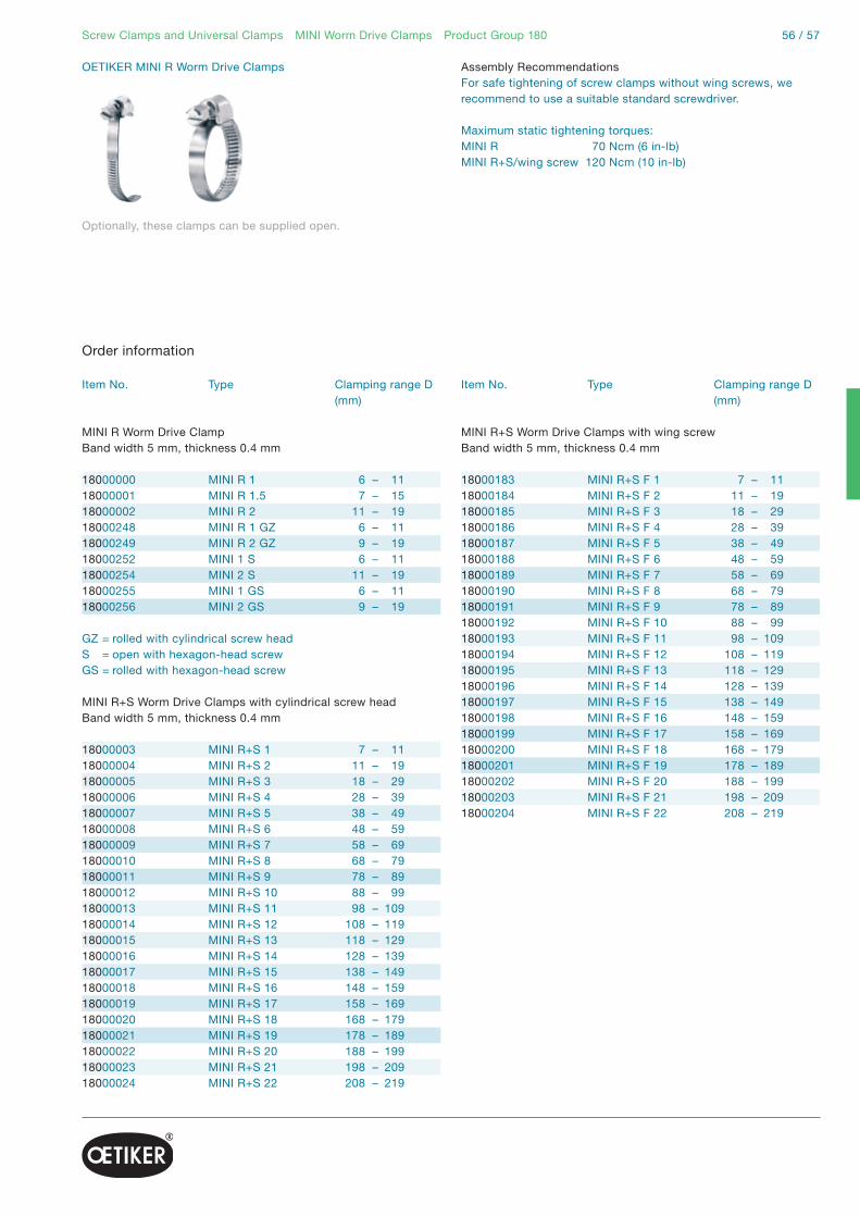
56 / 57Screw Clamps and Universal Clamps MINI Worm Drive Clamps Product Group 180
OETIKER MINI R Worm Drive Clamps
Optionally, these clamps can be supplied open.
Assembly RecommendationsFor safe tightening of screw clamps without wing screws, we recommend to use a suitable standard screwdriver.
Maximum static tightening torques:MINI R 70 Ncm (6 in-lb)MINI R+S/wing screw 120 Ncm (10 in-lb)
Item No. Type Clamping range D (mm)
MINI R Worm Drive ClampBand width 5 mm, thickness 0.4 mm
18000000 MINI R 1 6 – 1118000001 MINI R 1.5 7 – 1518000002 MINI R 2 11 – 1918000248 MINI R 1 GZ 6 – 1118000249 MINI R 2 GZ 9 – 1918000252 MINI 1 S 6 – 1118000254 MINI 2 S 11 – 1918000255 MINI 1 GS 6 – 1118000256 MINI 2 GS 9 – 19
GZ = rolled with cylindrical screw headS = open with hexagon-head screwGS = rolled with hexagon-head screw
MINI R+S Worm Drive Clamps with cylindrical screw headBand width 5 mm, thickness 0.4 mm
18000003 MINI R+S 1 7 – 1118000004 MINI R+S 2 11 – 1918000005 MINI R+S 3 18 – 2918000006 MINI R+S 4 28 – 3918000007 MINI R+S 5 38 – 4918000008 MINI R+S 6 48 – 5918000009 MINI R+S 7 58 – 6918000010 MINI R+S 8 68 – 7918000011 MINI R+S 9 78 – 8918000012 MINI R+S 10 88 – 9918000013 MINI R+S 11 98 – 10918000014 MINI R+S 12 108 – 11918000015 MINI R+S 13 118 – 12918000016 MINI R+S 14 128 – 13918000017 MINI R+S 15 138 – 14918000018 MINI R+S 16 148 – 15918000019 MINI R+S 17 158 – 16918000020 MINI R+S 18 168 – 17918000021 MINI R+S 19 178 – 18918000022 MINI R+S 20 188 – 19918000023 MINI R+S 21 198 – 20918000024 MINI R+S 22 208 – 219
Order information
Item No. Type Clamping range D (mm)
MINI R+S Worm Drive Clamps with wing screwBand width 5 mm, thickness 0.4 mm
18000183 MINI R+S F 1 7 – 1118000184 MINI R+S F 2 11 – 1918000185 MINI R+S F 3 18 – 2918000186 MINI R+S F 4 28 – 3918000187 MINI R+S F 5 38 – 4918000188 MINI R+S F 6 48 – 5918000189 MINI R+S F 7 58 – 6918000190 MINI R+S F 8 68 – 7918000191 MINI R+S F 9 78 – 8918000192 MINI R+S F 10 88 – 9918000193 MINI R+S F 11 98 – 10918000194 MINI R+S F 12 108 – 11918000195 MINI R+S F 13 118 – 12918000196 MINI R+S F 14 128 – 13918000197 MINI R+S F 15 138 – 14918000198 MINI R+S F 16 148 – 15918000199 MINI R+S F 17 158 – 16918000200 MINI R+S F 18 168 – 17918000201 MINI R+S F 19 178 – 18918000202 MINI R+S F 20 188 – 19918000203 MINI R+S F 21 198 – 20918000204 MINI R+S F 22 208 – 219

Screw Clamps and Universal Clamps Universal Clamps Product Group 174
Universal ClampsProduct Group 174
Material174 All parts are stainless steel, Material no. 1.4301/UNS S30400
SeriesSize range width x thickness≥ 35.0 mm 10.0 x 0.5 mm≥ 80.0 mm 18.0 x 0.8 mm*
* For use with 18 mm screw lock
Perforated band: universally applicable for various diameters and widthsRatchet lock: installation and removal without toolsScrew lock: simple installation, high holding forceVarious supply options: kit format, bulk or to customer specification
Perforated steel band
Screw lock
The data in this catalogue are based on many years experience. They are intended for reference, not as design specifications.
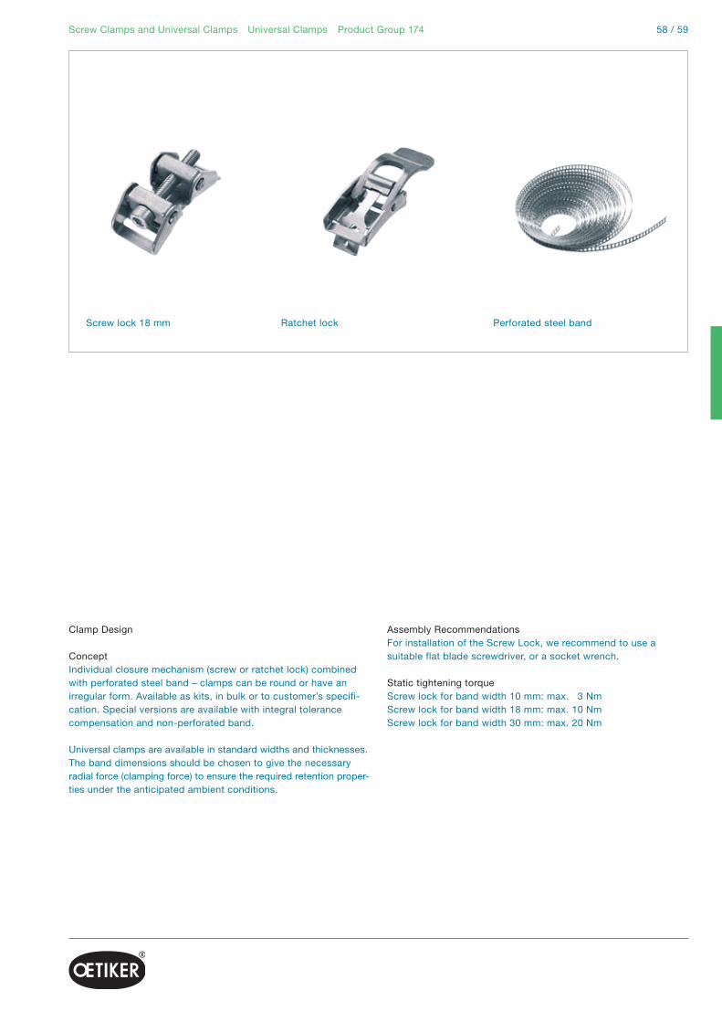
58 / 59Screw Clamps and Universal Clamps Universal Clamps Product Group 174
Clamp Design
ConceptIndividual closure mechanism (screw or ratchet lock) combined with perforated steel band – clamps can be round or have an irregular form. Available as kits, in bulk or to customer’s specifi-cation. Special versions are available with integral tolerance compensation and non-perforated band.
Universal clamps are available in standard widths and thicknesses. The band dimensions should be chosen to give the necessary radial force (clamping force) to ensure the required retention proper-ties under the anticipated ambient conditions.
Assembly RecommendationsFor installation of the Screw Lock, we recommend to use a suitable flat blade screwdriver, or a socket wrench.
Static tightening torqueScrew lock for band width 10 mm: max. 3 NmScrew lock for band width 18 mm: max. 10 NmScrew lock for band width 30 mm: max. 20 Nm
Screw lock 18 mm Perforated steel bandRatchet lock

Screw Clamps and Universal Clamps Universal Clamps Product Group 174
Determine the clamp length, e.g. wrap around object to be clamped and add approx. 50 mm.
Determine the clamp length, e.g. wrap around object to be clamped and add approx. 50 mm.
Screw lock type
Ratchet lock type
Cut off band to required length. To avoid possible injury remove sharp edges with a file and trim corners at an angle.
Cut off band to required length. To avoid possible injury remove sharp edges with a file and trim corners at an angle.
Insert approximately 30 mm of band material through the top of the retaining slot and fold backwards underneath the remaining strip.
Insert approximately 30 mm of band material through the top of the retaining slot and fold backwards underneath the remaining strip.
Position clamp over object. Insert free end of the band over the hooks and under the screw, protruding past the body of the screw lock. Engage the hooks in the perforations at the tightest possible position.
Place lever in open position, pre-form the end of the band to match the curvature of lock. Pass free end under tongue and through slot, so that the end extends beyond the lock body.
Tighten the clamp with a screwdriver or hexagon wrench.
Position clamp over object. With minimal force, press free end of band steel down and ratchet the lever back and fourth until tight. Firmly lock the lever down in the final re-tained position. “Securing dimple” prevents unintentional opening.
Assembly instructions

60 / 61Screw Clamps and Universal Clamps Universal Clamps Product Group 174
Item No. Ref. No. Size range (mm)
Screw lock
Compatible with band width 10 mm17400003 540R/10- 40 – 10017400002 540R/10+ 100 – …
Compatible with band width 18 mm17400005 540R/18- 80 – 15017400004 540R/18+ 150 – …
Ratchet lock
Compatible with band width 10 mm17400063 504R/60- 35 – 6017400064 504R/60+ 60 – …
Order information
Item No. Ref. No. Band length (m)
Perforated steel band
Width 10 mm, material thickness 0.5 mm17400067 501R/10 1017400081 501R/20 20
Width 18 mm, material thickness 0.8 mm17400077 518R/10 1017400079 518R/20 20

Screw Clamps and Universal Clamps Worm Drive Clamps Product Group 126 & 177
Worm Drive ClampsProduct Group 126 & 177
Clamp designOETIKER Worm Drive Clamps are technically advanced, multi-range hose clamps, which cover a very wide range of clamping diameters. Hoses of differing diameters can be securely connected with a single size.
Manufactured by cold-forming, the bands of these worm drive clamps have a slightly curved form. The depth of the thread impressions reduces to each side – the thread impressions have their full depth in the middle.
Worm drive clamps in material quality W2 have a 7 A/F hexagon-head screw with cross recess (Phillips). Clamps in materialquality W4 have a hexagon-head screw (7 A/F) with a standard screwdriver slot.
Recommended installationFor professional installation, we recommend using a flexible screwdriver. This tool ensures safe installation even in hard-to-reach locations. For series installation requiring high process reliability, electronically monitored OETIKER controlled-torque screwdrivers should be used.
Comply with DIN 3017: Embossed clamp band, large clamping range, high holding forceShort housing saddle: uniform radial load with good sealWeld-free body connection: secure connection, good corrosion resistanceSpecially formed strip edges: reduced risk of damage to parts being clamped
Material 126W2 Band and housing: stainless steel Material No. 1.4016/UNS S43000 Hexagon-head screw: steel, zinc-plated
Material 177W4 All parts: stainless steel Material No. 1.4301/UNS S30400
SeriesDiameter range width x thickness 8.0 – 160.0 mm 9.0 x 0.6 mm16.0 – 160.0 mm 12.0 x 0.7 mm
Other material qualities and diameter ranges on request.
Housing saddle
Housing with screw
The data in this catalogue are based on many years experience. They are intended for reference, not as design specifications.

62 / 63Screw Clamps and Universal Clamps Worm Drive Clamps Product Group 126 & 177
Static tightening torque:Clamping range B = 9 B = 128 – 20 2 + 0.5 NmFrom 12 – 160 3 + 0.5 NmFrom 16 – 160 5 + 0.5 Nm
Static test torque:Clamping range B = 9 B = 128 – 20 max. 2.6 NmFrom 12 – 160 max. 4 NmFrom 16 – 160 max. 6.5 Nm
Item No. Ref. No. Size range (mm)
Worm Drive Clamps W2Band width 9 mm, thickness 0.6 mm
12600257 WD9 8-12 C7 W2 8 – 1212600258 WD9 10-16 C7 W2 10 – 1612600260 WD9 12-22 C7 W2 12 – 2212600262 WD9 16-27 C7 W2 16 – 2712600263 WD9 20-32 C7 W2 20 – 3212600265 WD9 25-40 C7 W2 25 – 4012600266 WD9 30-45 C7 W2 30 – 4512600268 WD9 40-60 C7 W2 40 – 6012600269 WD9 50-70 C7 W2 50 – 7012600270 WD9 60-80 C7 W2 60 – 8012600271 WD9 70-90 C7 W2 70 – 9012600272 WD9 80-100 C7 W2 80 – 10012600273 WD9 90-110 C7 W2 90 – 11012600274 WD9 100-120 C7 W2 100 – 12012600275 WD9 110-130 C7 W2 110 – 13012600276 WD9 120-140 C7 W2 120 – 14012600277 WD9 130-150 C7 W2 130 – 15012600278 WD9 140-160 C7 W2 140 – 160
Worm Drive Clamps W2Band width 12 mm, thickness 0.7 mm
12600298 WD12 16-27 C7 W2 16 – 2712600299 WD12 20-32 C7 W2 20 – 3212600301 WD12 25-40 C7 W2 25 – 4012600302 WD12 30-45 C7 W2 30 – 4512600304 WD12 40-60 C7 W2 40 – 6012600305 WD12 50-70 C7 W2 50 – 7012600306 WD12 60-80 C7 W2 60 – 8012600307 WD12 70-90 C7 W2 70 – 9012600308 WD12 80-100 C7 W2 80 – 10012600309 WD12 90-110 C7 W2 90 – 11012600310 WD12 100-120 C7 W2 100 – 12012600311 WD12 110-130 C7 W2 110 – 13012600312 WD12 120-140 C7 W2 120 – 14012600313 WD12 130-150 C7 W2 130 – 15012600314 WD12 140-160 C7 W2 140 – 160
Order information
Item No. Ref. No. Size range (mm)
Worm Drive Clamps W4Band width 9 mm, thickness 0.6 mm
17700188 WD9 8-12 C7 W4 8 – 1217700189 WD9 10-16 C7 W4 10 – 1617700191 WD9 12-22 C7 W4 12 – 2217700193 WD9 16-27 C7 W4 16 – 2717700194 WD9 20-32 C7 W4 20 – 3217700196 WD9 25-40 C7 W4 25 – 4017700197 WD9 30-45 C7 W4 30 – 4517700199 WD9 40-60 C7 W4 40 – 6017700200 WD9 50-70 C7 W4 50 – 7017700201 WD9 60-80 C7 W4 60 – 8017700202 WD9 70-90 C7 W4 70 – 9017700203 WD9 80-100 C7 W4 80 – 10017700204 WD9 90-110 C7 W4 90 – 11017700205 WD9 100-120 C7 W4 100 – 12017700206 WD9 110-130 C7 W4 110 – 13017700207 WD9 120-140 C7 W4 120 – 14017700208 WD9 130-150 C7 W4 130 – 15017700209 WD9 140-160 C7 W4 140 – 160
Worm Drive Clamps W4Band width 12 mm, thickness 0.7 mm
17700229 WD12 16-27 C7 W4 16 – 2717700230 WD12 20-32 C7 W4 20 – 3217700232 WD12 25-40 C7 W4 25 – 4017700233 WD12 30-45 C7 W4 30 – 4517700235 WD12 40-60 C7 W4 40 – 6017700236 WD12 50-70 C7 W4 50 – 7017700237 WD12 60-80 C7 W4 60 – 8017700238 WD12 70-90 C7 W4 70 – 9017700239 WD12 80-100 C7 W4 80 – 10017700240 WD12 90-110 C7 W4 90 – 11017700241 WD12 100-120 C7 W4 100 – 12017700242 WD12 110-130 C7 W4 110 – 13017700243 WD12 120-140 C7 W4 120 – 14017700244 WD12 130-150 C7 W4 130 – 15017700245 WD12 140-160 C7 W4 140 – 160
Worm Drive Clamps W2B, W3, W5Band width 9 mm and 12 mmOn request

Full material cross-sectionover 360°:+ Constant pressure applied uni- formly around the circumferenceNominal diameter up to 120 mm:+ Suitable for universal application, in particular for thermoplastic componentsAluminium version:+ Reduced weight
Multi Crimp RingsMCR AL – Puzzle lock designAluminiumPG 150
p. 66
OETIKER will be pleased to helpyou find the correct choice for your application. Send sample parts and all relevant information for your specific application to OETIKER, and you will receive recommen-dations for product type, diameter, and method of installation.

64 / 65
Flexible diameter reduction:+ High, adjustable surface pressure+ Very easy to installLow installed height:+ Minimum space requirement+ No imbalance on rotating partsNominal diameter up to 50 mm:+ Especially suitable for cooling and heating water circuits, and for airbag systems
Flexible diameter reduction:+ High, adjustable surface pressure+ Very easy to installAluminium version – longitudinal welded:+ Economic alternative to stainless steel
Multi Crimp Rings Overview
MCR R – spirally weldedStainless steelPG 150
MCR AL – longitudinally welded AluminiumPG 150
p. 66 p. 66

Multi Crimp Rings Product Group 150
Multi Crimp RingsProduct Group 150
Material dimensionsOETIKER Multi Crimp Rings are available in a range of dimensions and materials. The band dimensions should be chosen to take into account the required radial force, the nature of the hose, to ensure the necessary sealing and/or retention properties under the relevant ambient conditions, and any mechanical loads on the MCR.
Puzzle design (interlock)The interlock is a mechanical connection employing very precise mating elements. Its design creates a positive mechanical con-nection. It ensures secure connection of the ring ends within the permissible load range.
OETIKER Multi Crimp Rings should be closed using the swaging tools developed and approved for them by OETIKER. The maximum practical diameter reduction depends on the diameter selected, as follows:
MCR diameter from 27 to 40 mmMax. diameter reduction = 5 mmMCR diameter from 40.5 to 120 mmMax. diameter reduction = 6 mm
MaterialsPuzzle lock: aluminium, Material No. 3.3535Spirally welded: stainless steel, Material No. 1.4301/UNS S30400Longitudinally welded: aluminium
RangeDiameter range 5.0–120.0 mm*
* Depending on product type
Some diameters and product variants are only available if an appropriate minimum quantity is ordered.
Full material cross-section over 360°: constant pressure applied uniformly around the circumferenceFlexible diameter reduction: high, adjustable surface pressure, very easy to installNominal diameter up to 120 mm: suitable for universal application, in particular for thermoplastic componentsLow installed height: minimum space requirement, no imbalance on rotating partsSpecially formed strip edges: reduced risk of damage to parts being clampedAluminium version*: reduced weight
Puzzle lock design Spirally welded Longitudinally welded
The data in this catalogue are based on many years experience. They are intended for reference, not as design specifications.

66 / 67Multi Crimp Rings Product Group 150
In the larger diameter range, the maximum diameter reduction is also restricted by the segment radii of the swaging tool. These must be chosen to correspond to the required outside diameter of the MCR after installation.
The installation process necessarily involves changes to the structure of the band material and changes in band dimensions, because the diameter reduction of an MCR is caused by the tool.
It is important to take into account that these changes become more severe the smaller the diameter of the selected MCR. The reason for this is that the quantity of material available, in effect the length of band, becomes smaller as the diameter is reduced.The band length is reduced according to the formula:
Reduction in circumference = diameter reduction x π
For shorter installation times, easier positioning and lower stresses in the MCR material, the nominal diameter of the MCR should be as close as possible to the diameter of the part being clamped.
The required degree of compression, or the surface pressure exerted on the part being clamped by an MCR depends on the radial force which, in turn, determines the retention and sealing properties. The load on the interlock element is determined by the reaction force that counters the surface pressure. The surface pressure must be individually determined for each application.
When the specially developed OETIKER swaging tool is used, the inner surface of an MCR applies an almost completely uniform surface pressure to the part being clamped over the full 360°. The result: optimum installation and practically no out-of-balance forces from projecting parts.
Spirally weldedAs an alternative to OETIKER Multi Crimp Rings with interlock, in the range 4 mm to 50 mm, OETIKER Multi Crimp Rings are available made from spirally welded stainless steel tube (Material No. 1.4301/UNS S30400).
Manufacturing processA special feature of the manufacture of this type of MCR is the spiral rolling and welding of flat strip material to form tubes. This process was specially developed for the well-proven 1-Ear and 2-Ear Clamps from tube, and ensures the uninterrupted, robust geometry of these MCRs, known as the “One-piece Design”.Flat strip material is rolled at an angle of approximately 45º into a forming die and the spiral seam of the tube so formed is TIG welded.
Subsequent calibration and cutting-off processes generate the appropriate MCR dimensions, and an abrasive barrel-finishing process eliminates burrs.
Diameter reductionThe maximum possible diameter reduction of MCRs made from tube is also diameter-dependent. It should be kept as small as possible. OETIKER will be pleased to help you find the correct choice for your specific application.
Recommendations for installing MCRsOETIKER Multi Crimp Rings should be closed using the swaging tools developed for them. The OETIKER Swaging Tool ELS 01 offers many advantages for industrial use, for example, opening of the fixture for optimum accessibility and automatic locking, through to the electronic verification of process parameters for force-priority closure. Alternatively, conventional multi segment hydraulic and pneumatic swaging tools are commercially available.
Tolerance compensationTolerance compensation when installing OETIKER Multi Crimp Rings depends entirely on the function sequence of the installation tool. Fundamentally, with diameter-priority installation of OETIKER Multi Crimp Rings, tolerance compensation is impos-sible, because the MCR is simply closed to a specified diameter. This means that the tolerances of components exert their full effect on the degree of compression or the surface pressure applied to the part being clamped. With this type of installation, everything else is subjugated to achieving a defined diameter.Thus, tolerance compensating installation of an MCR can only be achieved with force-priority regulation. Or, to put it a different way, the basic principle here is not pressing to a given diameter, but achieving an empirically determined closing force, and so the surface pressure associated with it.
With the innovative closure concept of the “OETIKER ELS 01”, high process reliability combined with the force-priority, verified installation of OETIKER Multi Crimp Rings is assured. Gauges for checking the closing force are also available.
MCR AL – longitudinally weldedOn request

Radial installation:+ Clamp can be opened to clear obstructions for axial or radial installation Quick closure:+ Positive engagement of interlock ensures simple, secure closureHigh-quality stainless steel:+ High holding properties even at temperatures up to 1000°CFlexible:+ Can be supplied closed or pre-shaped
Applications:Exhaust systemsHeating systemsetc.
1-Ear Clamp SVPG 153
Samples for Special Clamps(on request)
OETIKER will be pleased to helpyou find the correct choice for your application. Send sample parts and all relevant information for your specific application to OETIKER, and you will receive recommen-dations for product type, diameter, and method of installation.

68 / 69
Compact:+ Stable solutions for securing components with circular cross- sectionsFlexible:+ Customer-specific versions for form and functionCoated material:+ High retention properties+ good corrosion resistance
Application:Gas generatorsSanitary pipesCompressed air linesetc.
Open:+ Simple, radial installation for ergonomic handlingFlexible:+ Customer-specific modifications are possibleBridged ear:+ Good sealing and excellent retention properties
Application:Exhaust systemsAirbagsetc.
Special Clamps Overview
1-Ear Clamp “Open End”PG 195
1-Ear Clamp with studPG 103
V-Profile:+ Secure and quickly installed connectionsClamp ear:+ Compact, robust fastening+ Tolerance compensationFlexible:+ Customer-specific versions for form and function
Application:Exhaust systemsFilter unitsSuction and compressed air hose(heat shields)etc.
1-Ear V-Profile ClampPG 190

Simple uncoupling and providesdust protection at the same time.
Quick Connectors
Threads and nominal bores for usewhere space is restricted.
Uncoupling possible with correct tool.
Thread-optimized range Thread-optimized range with combined release and dust-protection sleeve
OETIKER will be pleased to helpyou find the correct choice for your application. The mode of operation described under Quick Connectors is the basis for further development.Connection variants and materials can be modified.

70 / 71
Alternative connections:Hose connection for use with clamps, Multi Crimp Rings or pressed sleeves.
Space-saving:Thread and nominal bore increased in size so that nipple is within the connector.
Alternative connections:Thread sealing: The use of a taper achieves a positive, mechanical connection.
Quick Connectors Overview
Medium can flow in onedirection only:Integral non-return valve withinthe threaded boss
Hose connection variantwith integrated release and dust-protection sleeve
Length-optimized range with self-sealing taper
Thread-optimized range withintegral non-return valve

Quick ConnectorProduct Group 200
Compact: Tube end or nipple fits directly into connectorNo pressure drop: In the Quick Connector, the medium does not have to change direction, and there are no restrictionsSimple connection: Quick and easy: just insert the tube or nipple – no tool needed.Security: The groove in the tube or nipple ensures a mechanical connectionStrength: Unique design results in maximum burst pressure and retaining force Flexible connections: machined components allow modification to meet customers’ requirements
Quick Connectors Product Group 200
MaterialBody: Material No. 1.0737/UNS G12144Protection against corrosion on requestCirclip: Material No 1.4310/UNS S30100O-Ring: FPM
Other material on request
The data in this catalogue are based on many years experience. They are intended for reference, not as design specifications.
ApplicationOETIKER Quick Connectors are a new system for the fast, safe connection of fluid supply lines. They can be developed for specific applications and supplied in different versions to suit customers’ requirements. Because they can be fitted without tools, OETIKER Quick Connectors are the optimal connector for numerous industrial applications. OETIKER Quick Connectors drastically reduce installation times. OETIKER Quick Connectors are suitable for applications that make severe demands – whether as a connection element for safety-relevant components, or for installation on oil coolers, gearboxes, turbo-units, etc.
Process monitoringProcess monitoring is carried out mechanically. With appropriatemodification of the plug or tube, visual process monitoring is also possible.
Temperature rangeThe temperature range depends on the seal material and is defined in cooperation with the customer. O-rings in commercially available sizes are used.

72 / 73
Length-optimized range
DN A L SW 8 M14 x 1.5 13.9 19.010 M16 x 1.5 16.5 22.012 M18 x 1.5 16.5 24.015 M22 x 1.5 17.0 27.018 M27 x 2.0 21.5 32.0
Lengths in mm
Thread-optimized range
DN A L SW 8 M12 x 1.5 24.5 17.010 M14 x 1.5 27.0 19.012 M16 x 1.5 28.0 22.015 M18 x 1.5 29.0 24.018 M22 x 1.5 36.4 27.0
Lengths in mm
SW
L
A
L
SW
A
Functionality
To make the connection, push the grooved tube/adaptor into the Quick Connector until it engages.
To disconnect, push the disconnection sleeve/pincer into the Quick Connector to the stop, hold it in this position, and pull out the tube/adaptor.
Quick Connectors Product Group 200
Operating pressureThe permissible operating pressure is directly dependent on the O-ring selected, the temperature, and the quality of the male component. It must always be determined in relation to the application.
Pull-out load on QC tubeDN8–DN18 > 6500 N
Cracking pressureDN 8 > 1100 bar10 > 900 bar12 > 700 bar15 > 600 bar18 > 400 bar

Reliable process with electronicmonitoring of all specified parameters – 100% documentation
Complete integration into automated systems
Communication via PLC and PC
For universal use
Verification of closing force of installation tools
Ensures uniform, reproducible process quality
Installation Tools Electronically controlled pneumaticPincers OETIKER ELK 01
Test Equipment
p. 80p. 76
OETIKER will be pleased to helpyou find the correct choice for your application. Send sample parts and all relevant information for your specific application to OETIKER, and you will receive recommen-dations for product type, diameter, and method of installation.

74 / 75
High process reliability
Efficient, uniform assembly
Cordless version for flexible use
Manual closure of clamps Installation of Multi Crimp Rings
Separable or vertical opening for optimum component access
Intermeshing swaging segments guarantee 360° degree compression of MCR
Fast and simple exchange of swaging jaws
Installation Tools Overview
Pincers pneumatic + cordless Manual closing tools Swaging tools
p. 83 p. 92 p. 94

Test EquipmentOETIKER CAL 01
Ensures uniform, reproducible process qualityProvides an interface for data exchange with any OETIKER electronically controlled installation toolAC or DC operationConvenient carrying case
Closing forces for OETIKER ClampsAll types of OETIKER Ear Clamps and Low Profile Clamps that can be closed using a pneumatic pincer should be closed with a recommended, uniform force. This results in a constant, repro-ducible tensile stress in the clamp material within the permissible limits and without overloading the individual elements of the assembly.
The “Test Equipment CAL 01” is used to adjust and verify the applied closing force. To determine the recommended closing force for a specific product, please refer to the respective clamp data.
ImportantIn order to ensure uniform and reproducible process quality, OETIKER recommends verifying the closing forces of installation tools daily. In addition, stable compressed air quality and volume is required. To comply with the applicable local standards for test equipment, the CAL 01 should be calibrated at least once a year by an authorized institution. Please contact OETIKER regarding this service.
Installation Tools Test Equipment
Rights to make technical changes in the interests of further development reserved.
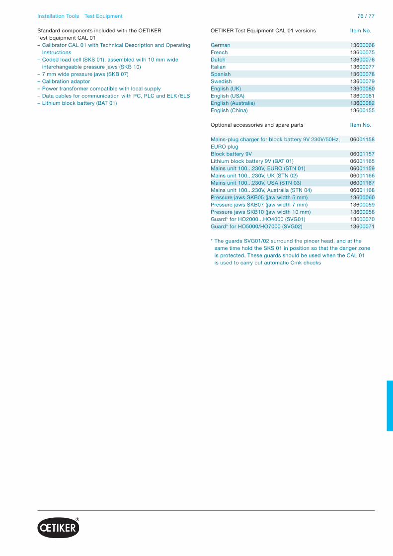
76 / 77
Standard components included with the OETIKERTest Equipment CAL 01– Calibrator CAL 01 with Technical Description and Operating Instructions– Coded load cell (SKS 01), assembled with 10 mm wide interchangeable pressure jaws (SKB 10)– 7 mm wide pressure jaws (SKB 07)– Calibration adaptor– Power transformer compatible with local supply– Data cables for communication with PC, PLC and ELK / ELS– Lithium block battery (BAT 01)
* The guards SVG01/02 surround the pincer head, and at the same time hold the SKS 01 in position so that the danger zone is protected. These guards should be used when the CAL 01 is used to carry out automatic Cmk checks
OETIKER Test Equipment CAL 01 versions Item No.
German 13600068French 13600075Dutch 13600076Italian 13600077Spanish 13600078Swedish 13600079English (UK) 13600080English (USA) 13600081English (Australia) 13600082English (China) 13600155
Optional accessories and spare parts Item No.
Mains-plug charger for block battery 9V 230V/50Hz, 06001158EURO plug Block battery 9V 06001157Lithium block battery 9V (BAT 01) 06001165Mains unit 100...230V, EURO (STN 01) 06001159Mains unit 100...230V, UK (STN 02) 06001166Mains unit 100...230V, USA (STN 03) 06001167Mains unit 100...230V, Australia (STN 04) 06001168Pressure jaws SKB05 (jaw width 5 mm) 13600060Pressure jaws SKB07 (jaw width 7 mm) 13600059Pressure jaws SKB10 (jaw width 10 mm) 13600058Guard* for HO2000...HO4000 (SVG01) 13600070Guard* for HO5000/HO7000 (SVG02) 13600071
Installation Tools Test Equipment
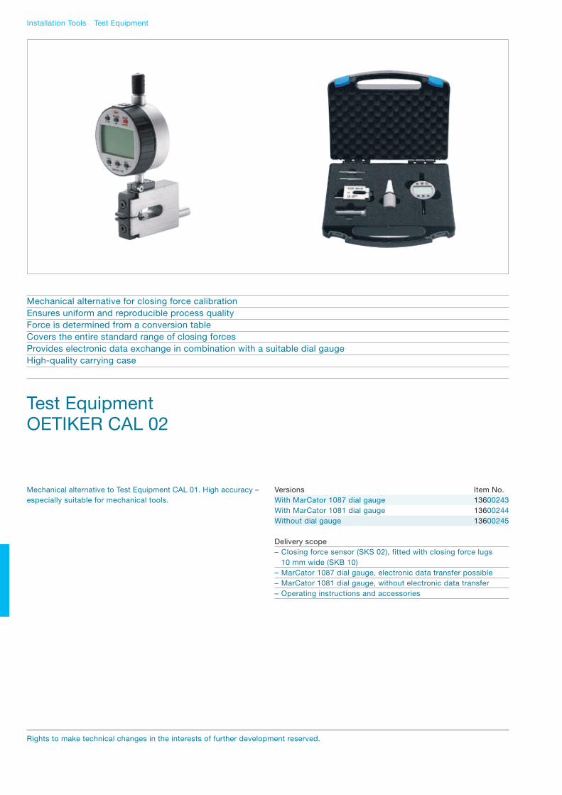
Versions Item No.With MarCator 1087 dial gauge 13600243With MarCator 1081 dial gauge 13600244Without dial gauge 13600245
Delivery scope– Closing force sensor (SKS 02), fitted with closing force lugs 10 mm wide (SKB 10)– MarCator 1087 dial gauge, electronic data transfer possible– MarCator 1081 dial gauge, without electronic data transfer– Operating instructions and accessories
Test EquipmentOETIKER CAL 02
Mechanical alternative for closing force calibrationEnsures uniform and reproducible process qualityForce is determined from a conversion tableCovers the entire standard range of closing forcesProvides electronic data exchange in combination with a suitable dial gaugeHigh-quality carrying case
Mechanical alternative to Test Equipment CAL 01. High accuracy – especially suitable for mechanical tools.
Installation Tools Test Equipment
Rights to make technical changes in the interests of further development reserved.

78 / 79
Types of OETIKER Closing Force Gauges Item No.OETIKER SKM 01 13900631OETIKER SKM 02 13900632
Delivery scope OETIKER SKM 01/SKM 02– Closing Force Gauge– Operating instructions
Technical data SKM 01Dimensions: ca. 100 x 19.5 x 44 mmWeight: ca. 230 gClosing force range: 1200 N–3400 NGraduation: 200 N
Technical data SKM 02Dimensions: ca. 100 x 19.5 x 44 mmWeight: ca. 240 gClosing force range: 3500 N–7500 NGraduation: 500 N
Test EquipmentOETIKER SKM 01 & 02
Economical alternative for closing force calibrationForce indicated by a pointer on a scaleEnsures uniform and reproducible process qualityTwo models available to suit closing force rangeDeveloped for ear clamp installation toolsRobust plastic carrying case
Installation Tools Test Equipment
Closing Force Gauges SKM 01/02 offer economical solutions for verifying the closing forces in small series and service applications. Suitable for calibrating installation tools for ear clamps.

Electronically Controlled Pneumatic Pincer OETIKER ELK 01
Process reliability, electronic monitoring of all specified parameters – 100% documentationForce or stroke-priority action, either with or without initial holding featureSingle, sequential or signal-controlled operationComplete integration into automated systemsFor efficient, verified assembly
The control unit is selected by language. The pincer unit is deter-mined by the type of OETIKER clamp to be installed, the required closing force, and the available air pressure. The pincer and control unit together form a complete unit. To obtain the optimum closing force, please refer to the technical information for the product being installed, and take into account the availability of special pincer heads.
OETIKER will be pleased to help you find the correct choice for your application. Data log acquisition from an OETIKER ELK 01, when connected to a PC, is available by installing the “CPM Clamp Process Monitoring” software – Item No. 13600121).
Standard hose/cable length of the Trigger Unit is 3 m. Alternative hose/cable lengths, also as angled versions, on request
Selection exampleFor a closing force of ca. 3000 N using an HO 3000 EL, the available inlet pressure must be at least 6 bar. The closing force itself must be set to the required data by changing parameters in the ELK 01 control unit. This can be done using a PC and a sequence programmed into the ELK 01, or by an external control signal. A closing force tester, for example Test Equipment CAL 01, is used to determine and set the correct closing force.
Trigger unit ELTergonomic handling(ELT = electronic version with extended trigger)
Installation Tools Electronically Controlled Pneumatic Pincer OETIKER ELK 01
Control Unit Trigger unit EL(EL = electronic version)
Rights to make technical changes in the interests of further development reserved.

80 / 81Installation Tools Electronically Controlled Pneumatic Pincer OETIKER ELK 01
Type of pincer Standard trigger unit EL EL without pincer headHO 2000 ELPincer complete 13900187 13900188 13900189 13900190 13900191 - - - 13900231 Replacement-jaw kit 13900166 13900167 13900168 13900169 13900163 - - - HO 3000 ELPincer complete - 13900192 13900193 13900194 13900195 13900196 - - 13900232 Replacement-jaw kit - 13900167 13900168 13900169 13900163 13900170 - - HO 4000 ELPincer complete - - - - 13900199 13900200 - - 13900233 Replacement-jaw kit - - - - 13900163 13900170 - - HO 5000 ELPincer complete - - - - - - 13900201 13900202 13900234 Replacement-jaw kit - - - - - - 13900164 13900165 HO 7000 ELPincer complete - - - - - - 13900203 13900204 13900547 13900235 Replacement-jaw kit - - - - - - 13900164 13900165 13900545Calibration adapter** 13600016 - - - - - - - - 13600016
Pincer headsJaw width (mm) 5.5 7.5 7.5 10.2 10.2 10.2 10.5 10.5 14.5Open gap (mm) 8.6 11.6 13.2 11.6 13.2 16.2 13.7 16.6 16.6For ear width* (mm) </= 7 8 10 8 10 13 10 13 13Item No. 13900156 13900152 13900148 13900144 13900119 13900140 13900112 13900097 13900544
* measured inside
Selection of complete pincer systems
Type of pincer Standard Trigger unit ELT with extended trigger ELT without pincer headHO 2000 ELTPincer complete 13900529 13900530 13900496 13900531 13900532 - - - 13900333 Replacement-jaw kit 13900166 13900167 13900168 13900169 13900163 - - - HO 3000 ELT Pincer complete - 13900533 13900534 13900535 13900373 13900536 - - 13900335 Replacement-jaw kit - 13900167 13900168 13900169 13900163 13900170 - - HO 4000 ELT Pincer complete - - - - 13900539 13900540 - - 13900337 Replacement-jaw kit - - - - 13900163 13900170 - - HO 5000 ELTPincer complete - - - - - - 13900525 13900526 13900339 Replacement-jaw kit - - - - - - 13900164 13900165 HO 7000 ELT Pincer complete - - - - - - 13900382 13900541 13900723 13900341 Replacement-jaw kit - - - - - - 13900164 13900165 13900545Calibration adapter** 13600016 - - - - - - - - 13600016
** already included in CAL 01
Item numbers in bold type are included in the recommended basic equipment. Replacement jaw kit = left and right pincer jaws complete with all necessary parts. The jaw width must be at least 0.5 mm wider than the band used for the clamps to be installed. The opening gap should be wide enough for the largest ear.
Control unit – numbers for languages/countries (mains plug) D CH F NL E I S UK USA AUS China (E) Japan (E)13600219 13600230 13600220 13600223 13600222 13600221 13600224 13600225 13600226 13600227 13600228 13600229

Installation Tools Electronically Controlled Pneumatic Pincer OETIKER ELK 01
Rights to make technical changes in the interests of further development reserved.
Pincer headsJaw width (mm) 5.5 7.5 7.5 10.2 10.2 10.2 Open gap (mm) 8.6 11.6 13.2 11.6 13.2 16.2 For ear width* (mm) </= 7 8 10 8 10 13 Item No. 13900156 13900152 13900148 13900144 13900119 13900140
Type of pincerHO 2000 EL A (mm) 325.0 324.0 324.0 324.0 324.0 - B (mm) 74.0 73.0 73.0 73.0 73.0 - C (mm) 101.0 101.0 101.0 101.0 101.0 - D (mm) 5.5 7.5 7.5 10.2 10.2 - E (mm) 12.3 13.3 13.3 14.9 14.9 -HO 3000 EL A (mm) - 363.0 363.0 363.0 363.0 368.0 B (mm) - 73.0 73.0 73.0 73.0 78.0 C (mm) - 140.0 140.0 140.0 140.0 140.0 D (mm) - 7.5 7.5 10.2 10.2 10.2 E (mm) - 13.3 13.3 14.9 14.9 14.9HO 4000 EL A (mm) - - 402.0 402.0 402.0 407.0 B (mm) - - 73.0 73.0 73.0 78.0 C (mm) - - 179.0 179.0 179.0 179.0 D (mm) - - 7.5 10.2 10.2 10.2 E (mm) - - 13.3 14.9 14.9 14.9
Pincer headsJaw width (mm) 10.5 10.5 Open gap (mm) 13.7 16.6 For ear width* (mm) 10 13 Item No. 13900112 13900097
Type of pincerHO 5000 EL A (mm) 420.0 425.0 B (mm) 102.0 107.0
HO 2000 EL/HO 3000 EL/HO 4000 EL
Pincer headsJaw width (mm) 10.5 10.5 14.5 Open gap (mm) 13.7 16.6 16.6For ear width* (mm) 10 13 13Item No. 13900112 13900097 13900544
Type of pincerHO 7000 EL A (mm) 511.0 516.0 516.0 B (mm) 102.0 107.0 107.0
* measured inside
D
E
A
C 114 36.5B
47 50
HO 5000 EL
HO 7000 EL
10.5 16
.6
A
36.5114167.5B
54 50
A
B 36.5114258.5
114 30
54 50
10.5 16
.6
Technical data

82 / 83Installation Tools Pneumatic Pincers OETIKER ME
Pneumatic Pincers OETIKER ME
Installation tool with high process reliabilityEfficient, uniform assemblyHigh-quality, complete pincer system for uniform clamp closuresFull range of pincer heads, for compatibility to all standard clampsAdaptation of special head designs possible
This high-quality, complete pincer system ensures the uniform installation of OETIKER clamps. The selection of the correct pincer body and head is dependent on the type of OETIKER clamp, the required closing force, and the air supply pressure that is available.
To obtain the optimum closing force, please refer to the technical information for the product being installed, and take into account the availability of special pincer heads.
Selection exampleFor a closing force of ca. 3000 N using an HO 3000 ME, the available inlet pressure must be at least 5-6 bar. The closing force must be set to the data given. To change the closing force, the inlet pressure must be adjusted. A closing force tester, for example Test Equipment CAL 01, is used to determine and set the correct closing force.

Installation Tools Pneumatic Pincers OETIKER ME
Pincer headsJaw width (mm) 5.5 7.5 7.5 10.2 10.2 10.2 10.5 10.5 14.5Open gap (mm) 8.6 11.6 13.2 11.6 13.2 16.2 13.7 16.6 16.6For ear width* (mm) </= 7 8 10 8 10 13 10 13 13Item No. 13900158 13900154 13900150 13900146 13900138 13900142 13900113 13900114 13900543
Type of pincer ME without pincer headHO 2000 MEPincer complete** 13900173 13900174 13900176 13900179 13900182 - - - - 13900226 Pincer complete*** 13900607 13900608 13900609 13900610 13900611 - - - - 13900612Replacement-jaw kit 13900166 13900167 13900168 13900169 13900163 - - - -HO 3000 ME Pincer complete** - 13900175 13900177 13900180 13900183 13900185 - - - 13900227 Pincer complete*** - 13900613 13900614 13900615 13900616 13900617 - - - 13900618Replacement-jaw kit - 13900167 13900168 13900169 13900163 13900170 - - - HO 4000 ME Pincer complete** - - - - 13900184 13900186 - - - 13900228 Pincer complete*** - - - - 13900619 13900620 - - - 13900621Replacement-jaw kit - - - - 13900163 13900170 - - -HO 5000 MEPincer complete** - - - - - - 13900161 13900162 - 13900229 Pincer complete*** - - - - - - 13900622 13900623 - 13900624Replacement-jaw kit - - - - - - 13900164 13900165 -HO 7000 ME Pincer complete** - - - - - - 13900171 13900172 13900546 13900230 Pincer complete*** - - - - - - 13900625 13900626 13900726 13900627Replacement-jaw kit - - - - - - 13900164 13900165 13900545
*** measured inside*** Swing Coupling thread G 1/4 (European)*** Swing Coupling thread NPT 1/4 (North American)
Selection of complete pincer systems
Rights to make technical changes in the interests of further development reserved.
Item numbers in bold type are included in the recommended basic equipment. Replacement jaw kit = left and right pincer jaws complete with all necessary parts. The jaw width must be at least 0.5 mm wider than the band used for the clamps to be installed. The opening gap should be wide enough for the largest ear.

84 / 85Installation Tools Pneumatic Pincers OETIKER ME
Pincer headsJaw width (mm) 5.5 7.5 7.5 10.2 10.2 10.2 Open gap (mm) 8.6 11.6 13.2 11.6 13.2 16.2 For ear width* (mm) </= 7 8 10 8 10 13 Item No. 13900158 13900154 13900150 13900146 13900138 13900142
Type of pincerHO 2000 ME A (mm) 214.0 213.0 213.0 213.0 213.0 - B (mm) 74.0 73.0 73.0 73.0 73.0 - C (mm) 101.0 101.0 101.0 101.0 101.0 - D (mm) 5.5 7.5 7.5 10.2 10.2 - E (mm) 12.3 13.3 13.3 14.9 14.9 -HO 3000 ME A (mm) - 252.0 252.0 252.0 252.0 257.0 B (mm) - 73.0 73.0 73.0 73.0 78.0 C (mm) - 140.0 140.0 140.0 140.0 140.0 D (mm) - 7.5 7.5 10.2 10.2 10.2 E (mm) - 13.3 13.3 14.9 14.9 14.9HO 4000 ME A (mm) - - 291.0 291.0 291.0 296.0 B (mm) - - 73.0 73.0 73.0 78.0 C (mm) - - 179.0 179.0 179.0 179.0 D (mm) - - 7.5 10.2 10.2 10.2 E (mm) - - 13.3 14.9 14.9 14.9
Pincer headsJaw width (mm) 10.5 10.5 14.5 Open gap (mm) 13.7 16.6 16.6 For ear width* (mm) 10 13 13Item No. 13900113 13900114 13900543
Type of pincerHO 5000 ME A (mm) 309.0 314.0 314.0 B (mm) 102.0 107.0 107.0
HO 2000 ME/HO 3000 ME/HO 4000 ME
Pincer headsJaw width (mm) 10.5 10.5 Open gap (mm) 13.7 16.6 For ear width* (mm) 10 13 Item No. 13900113 13900114
Type of pincerHO 7000 ME A (mm) 400.0 405.0 B (mm) 102.0 107.0
* measured inside
47
D
E
C
A
B
HO 5000 ME
HO 7000 ME
54
10.5 16
.6
A
167B
10.5
A
B
114 30
258
16.6
54
Technical data

Installation Tools Special Pincer Heads for Pneumatic Pincers OETIKER ME/EL
Special Pincer Headsfor Pneumatic Pincers OETIKER ME/EL
Pincer head with extended holdersWith either a 34.5 or an 80 mm extension length, these are used to make it easier to reach the clamp where access is restricted. Compatible with pincer types HO 2000 to HO 4000.
Selection of pincer headsThe jaw width must be at least 0.5 mm wider than the band used for the clamps to be installed. The opening gap should be wide enough for the largest ear.
** Measured inside** already included in CAL 01
Pincer headsJaw width D (mm) 5.5 7.5 10.2Open gap (mm) 8.6 13.2 13.2Height E (mm) 11.0 12.0 14.0For ear width* (mm) </=7 10 10
Type of pincerHO ME Pincer head complete 13900272 13900274 13900276 Replacement-jaw kit 13900166 13900168 13900163HO EL Pincer head complete 13900271 13900273 13900275 Replacement-jaw kit 13900166 13900168 13900163 Calibration adaptor** 13600016 13600016 13600016
Extension 34.5 mm
107
D
E
Pincer headsJaw width D (mm) 5.5 7.5 10.2Open gap (mm) 8.6 13.2 13.2Height E (mm) 11.0 12.0 14.0For ear width* (mm) </=7 10 10
Type of pincerHO ME Pincer head complete 13900278 13900280 13900282 Replacement-jaw kit 13900166 13900168 13900163HO EL Pincer head complete 13900277 13900279 13900281 Replacement-jaw kit 13900166 13900168 13900163 Calibration adaptor** 13600016 13600016 13600016
Extension 80 mm
D
153
EFor the installation of OETIKER Ear Clamps
Rights to make technical changes in the interests of further development reserved.

86 / 87Installation Tools Special Pincer Heads for Pneumatic Pincers OETIKER ME
* Measured inside
Special Pincer Headsfor Pneumatic Pincers OETIKER MEFor the installation of OETIKER Ear Clamps
Pincer heads with angled jawsSpecially for installing ear clamps where access is restricted. Suitable for ear clamps with 7 and 9 mm band widths. Compatible with pincer types HO 2000 to HO 4000.
Pincer heads 30°Jaw width (mm) 10.2Open gap (mm) 13.2For ear width* (mm) 10
Type of pincerHO ME Pincer head complete 13900706HO EL Pincer head complete 13900707 Replacement-jaw kit 13900708 Calibration set 13900722
Jaws angled at 30°
Pincer heads 60°Jaw width (mm) 10.2Open gap (mm) 13.2For ear width* (mm) 10
Type of pincerHO ME Pincer head complete 13900694HO EL Pincer head complete 13900697 Replacement-jaw kit 13900695 Calibration set 13900696
Jaws angled at 60°
10.2
30
84
1414
10.2
88.3
60
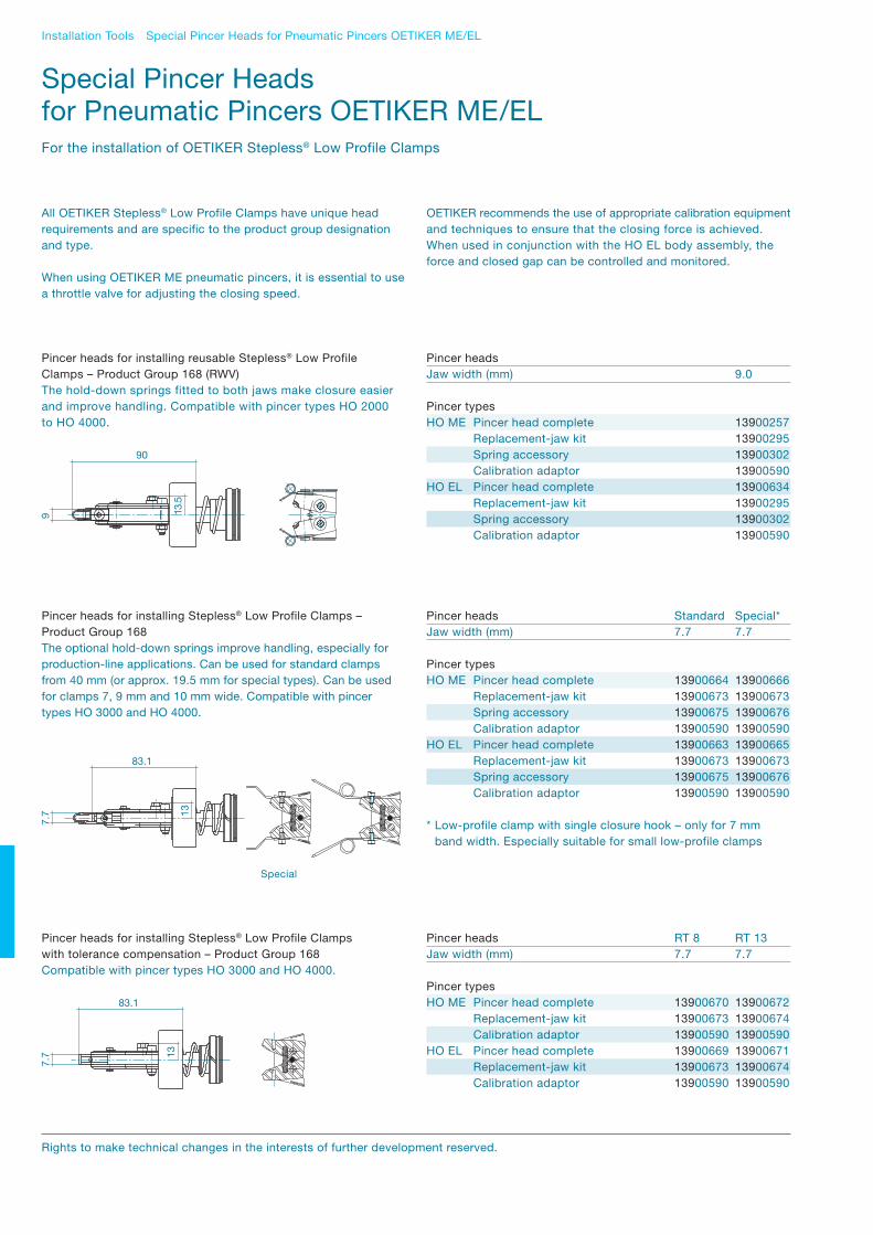
Installation Tools Special Pincer Heads for Pneumatic Pincers OETIKER ME/EL
Special Pincer Headsfor Pneumatic Pincers OETIKER ME/ELFor the installation of OETIKER Stepless® Low Profile Clamps
All OETIKER Stepless® Low Profile Clamps have unique head requirements and are specific to the product group designation and type.
When using OETIKER ME pneumatic pincers, it is essential to use a throttle valve for adjusting the closing speed.
OETIKER recommends the use of appropriate calibration equipment and techniques to ensure that the closing force is achieved. When used in conjunction with the HO EL body assembly, the force and closed gap can be controlled and monitored.
Pincer headsJaw width (mm) 9.0
Pincer typesHO ME Pincer head complete 13900257 Replacement-jaw kit 13900295 Spring accessory 13900302 Calibration adaptor 13900590HO EL Pincer head complete 13900634 Replacement-jaw kit 13900295 Spring accessory 13900302 Calibration adaptor 13900590
Pincer heads for installing reusable Stepless® Low Profile Clamps – Product Group 168 (RWV)The hold-down springs fitted to both jaws make closure easier and improve handling. Compatible with pincer types HO 2000 to HO 4000.
13.5
9
90
Pincer heads Standard Special*Jaw width (mm) 7.7 7.7
Pincer typesHO ME Pincer head complete 13900664 13900666 Replacement-jaw kit 13900673 13900673 Spring accessory 13900675 13900676 Calibration adaptor 13900590 13900590HO EL Pincer head complete 13900663 13900665 Replacement-jaw kit 13900673 13900673 Spring accessory 13900675 13900676 Calibration adaptor 13900590 13900590
* Low-profile clamp with single closure hook – only for 7 mm band width. Especially suitable for small low-profile clamps
Pincer heads for installing Stepless® Low Profile Clamps –Product Group 168The optional hold-down springs improve handling, especially for production-line applications. Can be used for standard clamps from 40 mm (or approx. 19.5 mm for special types). Can be used for clamps 7, 9 mm and 10 mm wide. Compatible with pincer types HO 3000 and HO 4000.
13
7.7
83.1
Pincer heads RT 8 RT 13Jaw width (mm) 7.7 7.7
Pincer typesHO ME Pincer head complete 13900670 13900672 Replacement-jaw kit 13900673 13900674 Calibration adaptor 13900590 13900590HO EL Pincer head complete 13900669 13900671 Replacement-jaw kit 13900673 13900674 Calibration adaptor 13900590 13900590
Pincer heads for installing Stepless® Low Profile Clampswith tolerance compensation – Product Group 168Compatible with pincer types HO 3000 and HO 4000.
13
83.1
7.7
Special
Rights to make technical changes in the interests of further development reserved.

88 / 89
Pincer headsJaw width (mm) 10.5
Pincer typesHO ME Pincer head complete 13900553 Replacement-jaw kit 13900554 Spring accessory 13900305 Calibration adaptor ME 13900306HO EL Pincer head complete 13900553 Replacement-jaw kit 13900554 Spring accessory 13900305 Calibration adaptor EL 13900307
Pincer head for installing Stepless® Low Profile Clamps withtolerance compensation Type 3 Heavy Duty – Product Group 168The hold-down spring is fitted to one jaw to assure effective interlock engagement. Compatible with pincer types HO 5000 and HO 7000.
Before deciding to use these special clamps and selecting the appropriate installation tool, please consult OETIKER
17
116
10.5
Installation Tools Special Pincer Heads for Pneumatic Pincers OETIKER ME/EL
Stepless® Low Profile Clamp 192 with tolerance compensation elementPincer heads 1/3 wavesJaw width (mm) 10.5
Pincer typesHO EL Pincer head complete 13900555 Replacement-jaw kit 13900556 Calibration adaptor EL 13900495
Pincer head for installing Stepless® Low Profile Clamp 192 –Product Group 192Compatible with pincer types HO 5000 EL and HO 7000 EL.
17
10.5
112
Pincer heads Jaw width (mm) 10.5
Pincer typesHO ME/EL On request
Pincer head for installing Clamps ER – Product Group 194Compatible with pincer types HO 2000 – 4000.
13
7.5
~112

Installation Tools Cordless Clamp Pincer OETIKER CP 01 & 02 & 03
Cordless Clamp Pincer OETIKER CP 01 & 02 & 03
Efficient, uniform and repeatable assemblyCordless installation tool for Ear ClampsLightweight, ergonomic design for easy handlingLED-display to indicate battery capacity and service interval
The Cordless Clamp Pincers CP 01, CP 02 and CP 03 are available as alternatives to the Pneumatic Pincers OETIKER ME. These devices offer good accuracy and ergonomic handling for fast, uniform assembly of OETIKER ear clamp types. The advantage of these closing tools is the cordless design and hence unrestricted, free motion during clamp assembly.
The hydraulic accumulator unit incorporates an automatic retraction function which returns the jaws to their open position when the selected maximum closing force is reached. The unit is also equipped with a special brake which stops jaw closure when the trigger is released.
The pincer head can be smoothly rotated 360° around the longitudinal axis in order to gain better access to tight corners and other hard-to-reach areas.
Delivery scope OETIKER CP 01 & 02 & 03– Cordless Clamp Pincer complete with pincer head and accumulator– Special screwdriver (to adjust closing force)– Operating Instructions (multi-lingual document)– Charger (compatible with local electrical supply voltage/ plug configuration)– Carrying case
Optional accessories and spare parts– Accumulator for CP 01/CP 02/CP 03 Item No.: 14000972– Screwdriver Item No.: 14000973
Rights to make technical changes in the interests of further development reserved.

90 / 91Installation Tools Cordless Clamp Pincer OETIKER CP 01 & 02 & 03
Pincer heads CP 01 CP 01 CP 02 CP 02 CP 03Jaw width (mm) 7.5 10.2 10.5 10.5 14.5Open gap (mm) 13.2 13.2 13.7 16.6 16.6For ear width* (mm) 10 10 10 13 13Item No. 13900683 13900659 13900662 13900660 13900711
Selection of pincer type according to language/country (mains plug) CP set without pincer headCP 01 (AUS) - 13900651 - - - 13900698Jaw replacement kit 13900163CP 01 (EU) - 13900650 - - - 13900699Jaw replacement kit 13900163CP 01 (UK) - 13900653 - - - 13900700Jaw replacement kit 13900163CP 01 (US) - 13900652 - - - 13900701Jaw replacement kit 13900163
CP 02 (AUS) - - 13900655 - - 13900702Jaw replacement kit 13900164CP 02 (EU) - - 13900654 - - 13900703Jaw replacement kit 13900164CP 02 (UK) - - 13900657 - - 13900704Jaw replacement kit 13900164CP 02 (US) - - 13900656 - - 13900705Jaw replacement kit 13900164
CP 03 (AUS) - - - - 13900713 13900717Jaw replacement kit 13900545 CO 03 (EU) - - - - 13900712 13900716Jaw replacement kit 13900545CP 03 (UK) - - - - 13900715 13900719Jaw replacement kit 13900545CP 03 (US) - - - - 13900714 13900718Jaw replacement kit 13900545
Special pincer heads 30° 60°Jaw width (mm) 10.2 10.2Open gap (mm) 13.2 13.2For ear width* (mm) 10 10Item No. 13900724 13900690
* Measured inside
Technical Data* CP 01 CP 02 CP 03Closing force range: 1000 N–4200 N** 4200 N–8500 N** 4500 N–9000 N*External dimensions: 410 x 56 x 80 mm 445 x 56 x 80 mm 445 x 56 x 80 mmWeight: 2050 g (4.5 lbs) 2250 g (5.0 lbs) 2300 g (5.0 lbs)Closing time: 2 seconds 2 seconds 2 seconds
** Approx. data** Closing force, depending on pincer head, can be determined via:– CAL 01, only with Software Generation V2.2 or higher– SKM 01 or SKM 02

Installation Tools Manual closing tools
Tool type Item No.
For Ear ClampsStandard pincers with straight jaws 14100082
For Ear ClampsPincers with side jaws for limited space 14100083
For Ear ClampsPincers with narrow jaws for limited space 14100037
For Ear ClampsManual pincer with force monitoring, On request OETIKER HMK 01. For correct installation and uniform closure. A vibration signal indicates when the preset force is reached.
For Stepless Low Profile Clamps 192Clamp pincers with special jaw form 14100134
Manual closing tools
Rights to make technical changes in the interests of further development reserved.
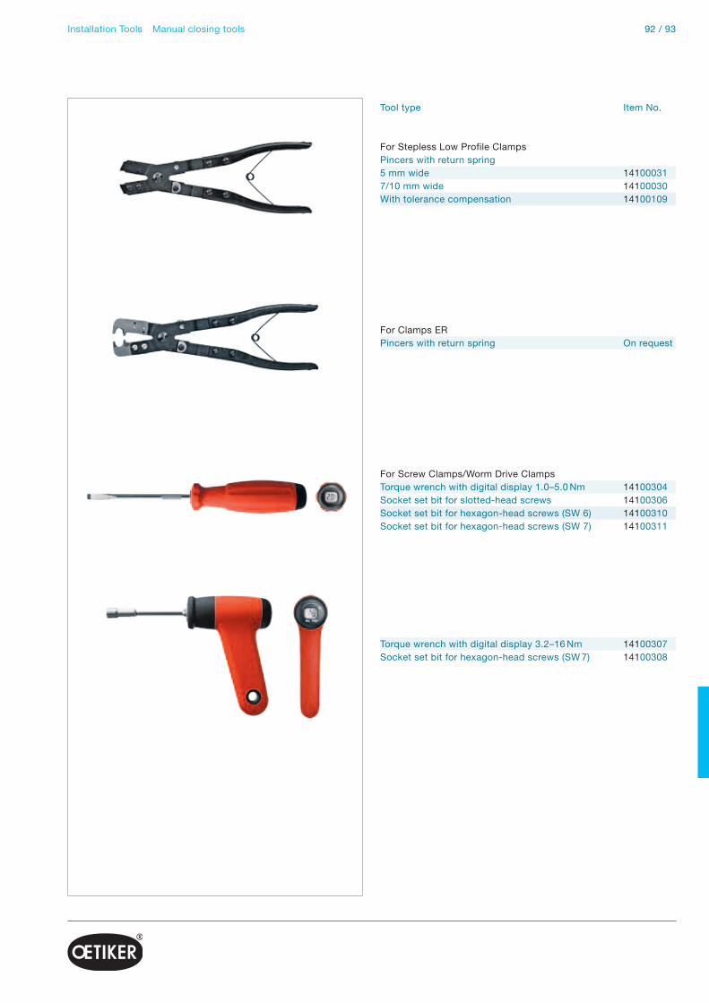
92 / 93Installation Tools Manual closing tools
Tool type Item No.
For Stepless Low Profile ClampsPincers with return spring5 mm wide 141000317/10 mm wide 14100030With tolerance compensation 14100109
For Clamps ERPincers with return spring On request
For Screw Clamps/Worm Drive ClampsTorque wrench with digital display 1.0–5.0 Nm 14100304Socket set bit for slotted-head screws 14100306Socket set bit for hexagon-head screws (SW 6) 14100310Socket set bit for hexagon-head screws (SW 7) 14100311
Torque wrench with digital display 3.2–16 Nm 14100307Socket set bit for hexagon-head screws (SW 7) 14100308
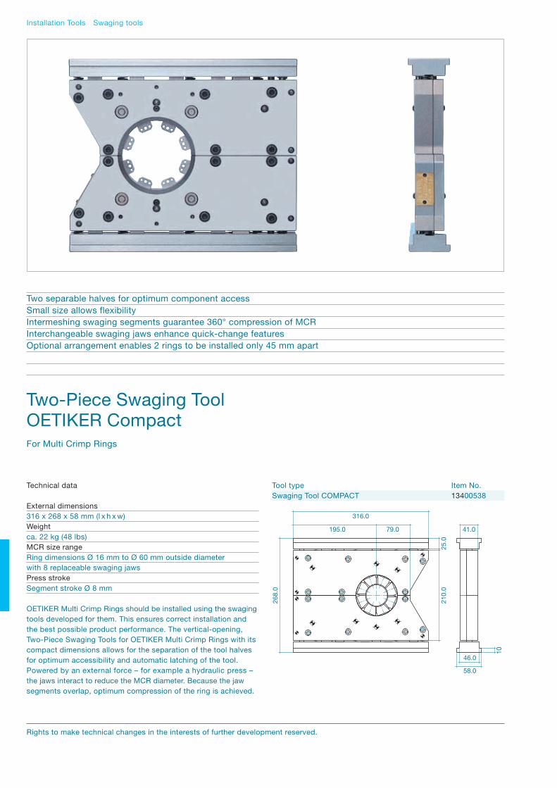
Installation Tools Swaging tools
Two-Piece Swaging Tool OETIKER Compact For Multi Crimp Rings
Two separable halves for optimum component accessSmall size allows flexibility Intermeshing swaging segments guarantee 360° compression of MCRInterchangeable swaging jaws enhance quick-change featuresOptional arrangement enables 2 rings to be installed only 45 mm apart
Technical data
External dimensions316 x 268 x 58 mm (l x h x w)Weightca. 22 kg (48 lbs)MCR size rangeRing dimensions Ø 16 mm to Ø 60 mm outside diameterwith 8 replaceable swaging jawsPress strokeSegment stroke Ø 8 mm
OETIKER Multi Crimp Rings should be installed using the swaging tools developed for them. This ensures correct installation and the best possible product performance. The vertical-opening, Two-Piece Swaging Tools for OETIKER Multi Crimp Rings with its compact dimensions allows for the separation of the tool halves for optimum accessibility and automatic latching of the tool. Powered by an external force – for example a hydraulic press – the jaws interact to reduce the MCR diameter. Because the jaw segments overlap, optimum compression of the ring is achieved.
Tool type Item No.Swaging Tool COMPACT 13400538
268.
0
210.
025
.0
316.0
195.0 79.0
58.0
46.0
41.0
10
Rights to make technical changes in the interests of further development reserved.

94 / 95Installation Tools Swaging tools
Hydraulic Swaging ToolOETIKER FlexFor Multi Crimp Rings
Single hinge for optimum accessibilityAutomatic locking when tool is activatedMinimal width for parallel operation, enabling multiple single-axis installationsIntermeshing swaging segments guarantee 360° compression of MCRInterchangeable swaging jaws enhance quick-change features
OETIKER Multi Crimp Rings should be installed using the swaging tools developed for them. This ensures correct installation and the best possible product performance.
The hydraulic swaging tool OETIKER Flex has many advantages for industrial applications: For example, the tool can be opened for unrestricted accessibility with automatic latching and a very compact width. Powered by the integrated hydraulic drive, the jaws interact to reduce the MCR diameter. Because the jaw segments overlap, optimum compression of the ring is achieved.
Tool type Item No.Swaging tool Flex 13401010
Technical data
External dimensionsComplete system including mobile bench: 1550 x 1450 x 700 mm (l x h x w)Swaging press: 1270 x 660 x 80 mm (l x h x w)
WeightIncluding mobile bench and hydraulic unit: ca. 220 kg
MCR size rangeRing dimensions 16 mm to 120 mm outside diameter with8 replaceable swaging jawsRing dimensions 121 mm to 132 mm outside diameter withspecial slides and jaws
Press strokeSegment stroke 8 mm

Installation Tools Swaging tools
Electronically Controlled Hydraulic Swaging Tool OETIKER ELS 01For Multi Crimp Rings
Process reliable installation with electronic monitoring of all specified parametersTool hinged for optimum accessibilityFully automatic locking when tool is operatedCan be installed parallel for simultaneous closure of several MCRsIntermeshing swaging segments guarantee 360° compression of MCRInterchangeable swaging jaws enhance quick-change features
OETIKER Multi Crimp Rings should be installed using the swaging tools developed for them. This ensures correct installation and the best possible product performance.
The electronically controlled Swaging Tool OETIKER ELS 01 is an innovative closing concept providing reliable installation with electronic monitoring of all specified parameters. This tool offersmany advantages for automotive and industrial applications, e.g. integration in automated processes, convenient programming using a PC, optimum component accessibility, automatic locking of the tool mechanism and low width. Powered by the integrated hydraulic drive, the jaws interact to reduce the MCR diameter.
Because the jaw segments overlap, optimum compression of the ring is achieved. Swaging can be carried out with either force or diameter priority. When using the force-priority method, the installation of OETIKER Multi Crimp Rings can compensate for variations in component tolerances. In addition, 100% documentation of closures is available by using the optional “Clamp Process Monitoring” software.
Technical Data
External dimensionsComplete system including mobile bench: 1550 x 1800 x 700 mm (l x h x w)Swaging press: 1270 x 660 x 80 mm (l x h x w)
Weightincluding mobile bench and hydraulic unit: ca. 240 kg
MCR size rangeRing dimensions 16 mm to 120 mm outside diameter with8 replaceable swaging jawsRing dimensions 121 mm to 132 mm outside diameter withspecial slides and jaws
Press strokeSegment stroke 8 mm
Rights to make technical changes in the interests of further development reserved.

96 / 97Installation Tools Swaging tools
The thrust force of the hydraulic cylinder is set by changing the parameters at the ELS 01 control unit. This is accomplished by means of a PC, programming the specifications of a sequence of consecutive installations, or, optionally, using an external control signal. Specially adapted Test and Calibrating Equipment, basedon the Calibrator CAL 01, is employed to calibrate the thrust force.
Example of an arrangement of swaging tools.Rings can be closed simultaneously.
Tool type Item No.
Swaging tool ELS 01With 3 x 400V/50–60Hz mains voltage 13401011For other voltages on requestCPM Clamp Process Monitoring Software 13600121Calibrating Equipment for ELS 01 on requestCalibration gauges on request
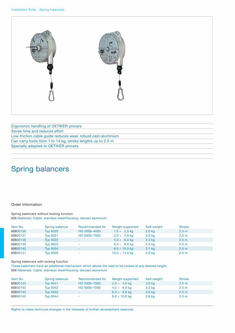
Installation Tools Spring balancers
Spring balancers
Ergonomic handling of OETIKER pincersSaves time and reduces effortLow-friction cable guide reduces wear, robust cast-aluminiumCan carry tools from 1 to 14 kg, stroke lengths up to 2.5 mSpecially adapted to OETIKER pincers
Spring balancers without locking function606 Materials: Cable: stainless steel/Housing: diecast aluminium
Item No. Spring balancer Recommended for Weight supported Self-weight Stroke60600136 Typ 9320 HO 2000–4000 1.0 ÷ 2.5 kg 2.0 kg 2.0 m60600137 Typ 9321 HO 5000–7000 2.0 ÷ 4.0 kg 2.0 kg 2.0 m60600138 Typ 9322 - 4.0 ÷ 6.0 kg 2.3 kg 2.0 m60600139 Typ 9323 - 6.0 ÷ 8.0 kg 2.5 kg 2.0 m60600140 Typ 9334 - 8.0 ÷ 10.0 kg 3.7 kg 2.5 m60600141 Typ 9335 - 10.0 ÷ 14.0 kg 4.0 kg 2.5 m
Order information
Spring balancers with locking functionThese balancers have an additional mechanism which allows the load to be locked at any desired height.606 Materials: Cable: stainless steel/Housing: diecast aluminium
Item No. Spring balancer Recommended for Weight supported Self-weight Stroke60600142 Typ 9341 HO 2000–7000 2.0 ÷ 4.0 kg 3.0 kg 2.5 m60600143 Typ 9342 HO 5000–7000 4.0 ÷ 6.0 kg 3.3 kg 2.5 m60600144 Typ 9343 - 6.0 ÷ 8.0 kg 3.6 kg 2.5 m60600145 Typ 9344 - 8.0 ÷ 10.0 kg 3.8 kg 2.5 m
Rights to make technical changes in the interests of further development reserved.
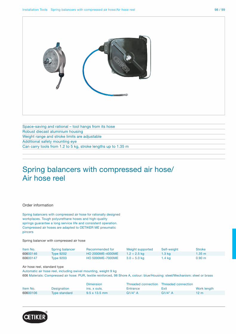
98 / 99Installation Tools Spring balancers with compressed air hose/Air hose reel
Spring balancers with compressed air hose/ Air hose reel
Space-saving and rational – tool hangs from its hoseRobust diecast aluminium housingWeight range and stroke limits are adjustableAdditional safety mounting eyeCan carry tools from 1.2 to 5 kg, stroke lengths up to 1.35 m
Spring balancer with compressed air hose
Item No. Spring balancer Recommended for Weight supported Self-weight Stroke60600146 Type 9202 HO 2000ME–4000ME 1.2 ÷ 2.5 kg 1.3 kg 1.35 m60600147 Type 9203 HO 5000ME–7000ME 3.0 ÷ 5.0 kg 1.4 kg 0.90 m
Order information
Air hose reel, standard typeAutomatic air hose reel, including swivel mounting, weight 9 kg606 Materials: Compressed air hose: PUR, textile reinforced, 98 Shore A, colour: blue/Housing: steel/Mechanism: steel or brass
Dimension Threaded connection Threaded connectionItem No. Designation ins. x outs. Entrance Exit Work length60600106 Type standard 9.5 x 13.5 mm G1/4" A G1/4" A 12 m
Spring balancers with compressed air hose for rationally designed workplaces. Tough polyurethane hoses and high-quality springs guarantee a long service life and consistent operation. Compressed air hoses are adapted to OETIKER ME pneumatic pincers

Couplings OETIKER Swing Couplings SC Series B1
Temperature range-20º to + 100ºC (NBR)-4º to + 212ºF
Operating pressure3 in Hg (100 mbar) to 360° psi (25 bar), connection/disconnection at maximum 200 psi (15 bar)
Materials, SealsDirection to selection and orderingsee catalogue Swing Couplings SC
Compatible withIndustrial Interchange 1/4", AMFLO C20B, Hansen 1000, Foster 3003, Parker B23, Cejn 310
Material CodeA = Steel, nickel plated/aluminiumB = Steel, Tenifer treatedC = Stainless steelE = Nitrile elastomer (NBR)I = Surface hardened steel, nickel platedS = Surface hardened steel, galvanizedZ = Zinc diecast, nickel plated, orange plastic coating
S B
E E C
I Z A
E
OETIKER Swing CouplingsSC Series B1
Comply with safety standard ISO 4414, EN 983Plug in accordance with ISO 6150-B-12, AFNOR: B-12 NF E 49-053 and US: MIL-C-4109Full flow, negligible loss of pressureSimple operation, no force requiredCompact design
Rights to make technical changes in the interests of further development reserved.

100 / 101Couplings OETIKER Swing Couplings SC Series B1
Swing couplingwith female thread
A Item No. LG1/4 20500307 56.1G3/8 20500308 57.6G1/2 20500309 61.1NPT1/4 20500311 56.1NPT3/8 20500312 58.6NPT1/2 20500313 64.6
A Item No. LG1/4 20500314 47.6G3/8 20500315 47.6G1/2 20500316 48.6NPT1/4 20500317 48.8NPT3/8 20500318 48.8NPT1/2 20500319 48.6
D Item No. L 6 mm 1/4" 20500320 68.1 8 mm 5/16" 20500321 68.110 mm 3/8" 20500322 68.1
D Item No. L6.5 x 10 20500324 62.68 x 12 20500325 65.6
with male thread
with hose stem
with PUR compression fitting
D
L
20
D
L
20
A
L
20
Plugwith male thread
A Item No. L SWG1/8 25500011 34.0 14G1/4 25500012 31.0 14NPT1/4 25500014 30.7 14NPT3/8 25500069 32.7 19
A Item No. L SWG1/4 25500016 43.0 17NPT1/4 25500018 43.0 17NPT3/8 25500274 45.0 19
D Item No. L Ø 6 mm 1/4" 25500019 51.0 14 8 mm 5/16" 25500020 51.0 1410 mm 3/8" 25500021 51.0 14
with female thread
with hose stem
SWA
L
SWA
L
D
L
Ø
For further versions and more information on our comprehensive range of couplings, please see the separate catalogue Swing Couplings SC.
A
L
20

Couplings OETIKER Swing Couplings SC
Swing couplingwith female thread
with male thread
with hose stem
with PUR compression fitting
Plugwith male thread
with female thread
with hose stem
Series A1 Series K Series C Series D Series E Series E1 [DN6] [DN6] [DN8] [DN8] [DN8] [DN8]
A Item No. Item No. Item No. Item No. Item No. Item No.G1/4 20500287 20500156 20500345 20500018 20500023 20500115G3/8 20500288 20500157 20500346 20500019 20500024 20500116G1/2 20500289 20500158 20500347 20500020 20500025 20500117NPT1/4 20500291 20500160 20500348 20500034 20500052 20500118NPT3/8 20500292 20500161 20500349 20500035 20500026 20500119NPT1/2 20500293 20500162 20500350 20500036 20500027 20500120
G1/4 20500294 20500163 20500351 20500053 20500028 20500121G3/8 20500295 20500164 20500352 20500021 20500029 20500122G1/2 20500296 20500165 20500353 20500022 20500045 20500123NPT1/4 20500297 20500166 20500375 20500426 20500214 20500383NPT3/8 20500298 20500167 20500354 20500037 20500030 20500124NPT1/2 20500299 20500168 20500355 20500038 20500031 20500125
D6 mm 1/4" 20500300 205001698 mm 5/16" 20500301 20500170 20500356 20500054 20500083 2050012610 mm 3/8" 20500302 20500171 20500357 20500055 20500084 2050012713 mm 1/2" 20500358 20500056 20500085 20500128
6.5 x 10 20500304 20500276 205000578 x 12 20500305 20500277 20500360 20500058 20500087 2050013011 x 16 20500361 20500059 20500088 20500131
A Item No. Item No. Item No. Item No. Item No. Item No.G1/8 25500000 25500093G1/4 25500001 25500091 25500023 25500032 25500041 25500101G3/8 25500092 25500024 25500033 25500042 25500102G1/2" 25500034NPT1/4 25500003 25500112 25500275 25500058 25500236 25500090NPT3/8 25500066 25500117 25500177 25500059 25500044 25500089NPT1/2" 25500060 25500045
G1/8 25500100G1/4 25500005 25500088 25500026 25500035 25500046 25500103G3/8 25500027 25500036 25500047 25500105G1/2" 25500037NPT1/4 25500007 25500119 25500276 25500061 25500237 25500104NPT3/8 25500068 25500178 25500062 25500049 25500106NPT1/2" 25500063 25500050
D 6 mm 1/4" 25500008 255001138 mm 5/16" 25500009 25500114 25500029 25500038 25500051 2550010710 mm 3/8" 25500010 25500115 25500030 25500039 25500052 2550010813 mm 1/2" 25500116 25500031 25500040 25500053 2550010916 mm 5/8" 25500110
OETIKER Swing Couplings SCSeries A1/K/C/D/E/E1
For further versions and more information on our comprehensive range of couplings, please see the separate catalogue Swing Couplings SC.
Rights to make technical changes in the interests of further development reserved.

102 / 103Compressed air accessories
Compressed air accessories
Compressed air service unit, filter-regulator, 30μmWith manual condensate release. All filter-regulators are supplied with mounting brackets and a 0–10 bar manometerMaterials: Housing: plastic, glass-fibre reinforced
Item No. Designation Connection Flow rate (l/min) Pressure range (bar) economic max. Inlet max. Outlet max.60200004 Filter-regulator G1/4“ I 550 550 10 8 Series 4060200069 Filter-regulator NPT1/4“ I 550 550 10 8 Series 40
Filter cartridgeMaterials: Ceramic
Item No. Designation60200026 Filter cartridge for Series 40, 30μm
PUR compressed air hoseLight air hose for universal application in trade and industryMaterial: Polyurethane with polyester textile reinforcement
Item No. Designation Dimensions Working Colour Roll length IDxOD (mm) press. exterior60100070 PUR air hose 6.0 x 10.0 15 bar smooth, blue 100 m60100071 PUR air hose 8.0 x 12.0 15 bar smooth, blue 100 m
Spiral hose, pre-assembled with coupling and plug DN6 Series B1Material: Spiral hose: PUR, 98 Shore A, colour: blue Coupling: steel, zinc-plated Plug-in nipple: steel, zinc-plated Kink-protection spiral: black polyamide, unbreakable
Item No. Designation Dimensions Outside-Ø length ID x OD (mm) of spiral60600029 Spiral hose 8.0 x 12.0 65 mm 4 m60600030 Spiral hose 8.0 x 12.0 65 mm 6 m
Spiral hose, pre-assembled with rotatable threaded connectionsMaterial: Spiral hose: PUR, 98 Shore A, colour: blue Connections: brass, zinc-plated
Item No. Designation Dimensions Connection Outside-Ø Working ID x OD threads of spiral length60100181 Spiral hose 6.5 x 10.0 G1/4“ A 52 mm 2 m60100130 Spiral hose 6.5 x 10.0 G1/4“ A 52 mm 4 m60100131 Spiral hose 6.5 x 10.0 G1/4“ A 52 mm 6 m
For further accessories, please see the separate accessory catalogue.

Printed in Switzerland on FSC certified paper

Headquarters SwitzerlandHans Oetiker AGMaschinen- und ApparatefabrikOberdorfstrasse 21CH-8812 Horgen (Zürich)T +41 44 728 55 55F +41 44 728 55 [email protected]
AustriaHans OetikerMaschinen- und ApparatebauGes.m.b.H.Eduard-Klinger-Strasse 19A-3423 St. Andrä-WördernT +43 2242 33 994-0F +43 2242 33 [email protected]
BelgiumOetiker Belgium N.V./S.A.Maaltecenter – Blok “G”Derbystraat 3019051 Gent/St. Denijs-WestremT +32 9 252 25 55F +32 9 252 25 [email protected]
CanadaOetiker Limited203 Dufferin Street SouthP. O. Box 5500Alliston, Ontario L9R 1W7T +1 705 435 [email protected]
P. R. ChinaOetiker Industries (Tianjin) Ltd.10 Shuangchenzhong RoadBeichen High Tech Industrial ParkTianjin 300400T +86 22 2697 1183F +86 22 2697 [email protected]
Czech RepublicHans Oetiker spol. s r. o.Videnska 116CZ-37833 Nová BystriceT +420 384 386513F +420 384 [email protected]
FranceOetiker Sarl9, rue Jean MoulinZA du Pré FuséF-77348 Pontault-Combault CedexT +33 1 60 29 90 39F +33 1 64 40 90 [email protected]
GermanyHans OetikerMetallwaren- & Apparatefabrik GmbHÜsenbergerstrasse 13D-79346 Endingen a. K.T +49 76 42 6 84-0F +49 76 42 6 [email protected]
Kurt Allert GmbH & Co. KGPostfach 1160Austrasse 36D-78727 Oberndorf a. N.T +49 74 23 87 70-0F +49 7 4 23 87 [email protected]
Hong KongOetiker Far East Limited2210 Tuen Mun Central Square22 Hoi Wing RoadTuen Mun NTT +852 2459 8211F +852 2459 [email protected]
HungaryOetiker Hungaria KFTVasvári P. U. 11H-9800 VasvárT +36 94 370 630F +36 94 370 [email protected]
IndiaOetiker India Private Ltd.N-14, Additional PatalgangaIndustrial AreaVillage Chavane, KhalapurRasayani 410 220Dist. RaigadT +91 2192 250107-12F +91 2192 [email protected]
JapanOetiker Japan Co. Ltd.Kaneko Bldg. A5-3-5 Nakamachi-dai, Tsuzuki-kuYokohama 224-0041T +81 45 949 3151F +81 45 949 [email protected]
NetherlandsOetiker Benelux B. V.Hertzstraat 38NL-6716 BT EdeT +31 318 63 71 71F +31 318 63 34 [email protected]
SpainOetiker España, S. A.Pol. Ind. Las SalinasC/Puente, 18E-11500 El Puertode Santa María (Cádiz)T +34 956 86 04 40F +34 956 87 17 [email protected]
United KingdomOetiker UK LimitedFoundry CloseGB-Horsham, Sussex RH13 5PXT +44 1403 26 04 78F +44 1403 24 06 [email protected]
USAOetiker, Inc.6317 Euclid StreetMarlette, Michigan 48453-0217T +1 989 635 3621F +1 989 635 [email protected]
The OETIKER Group: www.oetiker.com
www.oetiker.com
08902018 / 11.2010 / © OETIKER / Design: Moiré, Zürich