Embed Size (px)
Citation preview
8/12/2019 Connections 1
http://slidepdf.com/reader/full/connections-1 1/67
1
FUNDAMENTALS OF
CONNECTION DESIGN FOR
STRUCTURAL STEEL
BUILDINGS
8/12/2019 Connections 1
http://slidepdf.com/reader/full/connections-1 2/67
2
OUTLINE
Session 1 Connection Types/Classification/Load Paths/Limit States
Session 2 Direct Loaded Connections/Prying Forces/Bolt and Weld
Eccentricity
Session 3 Framing Connections
8/12/2019 Connections 1
http://slidepdf.com/reader/full/connections-1 3/67
3
OUTLINE
Session 4 Framing Connections Continued
Session 5 Moment Connections
Session 6 End-Plate Moment Connections/
Bracing Connections
8/12/2019 Connections 1
http://slidepdf.com/reader/full/connections-1 4/67
4
Session 1
TYPESCLASSIFICATION
LOAD PATHSLIMIT STATES
8/12/2019 Connections 1
http://slidepdf.com/reader/full/connections-1 5/67
5
CONNECTION TYPES
• TENSION CONNECTIONS
TrussHanger
Light and Heavy Bracing
8/12/2019 Connections 1
http://slidepdf.com/reader/full/connections-1 6/67
6
CONNECTION TYPES
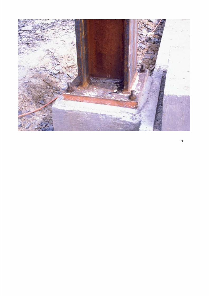
• COMPRESSION CONNECTIONS
Column SpliceBeam Bearing Plate
Column Base Plate
8/12/2019 Connections 1
http://slidepdf.com/reader/full/connections-1 7/67
7
8/12/2019 Connections 1
http://slidepdf.com/reader/full/connections-1 8/67
8
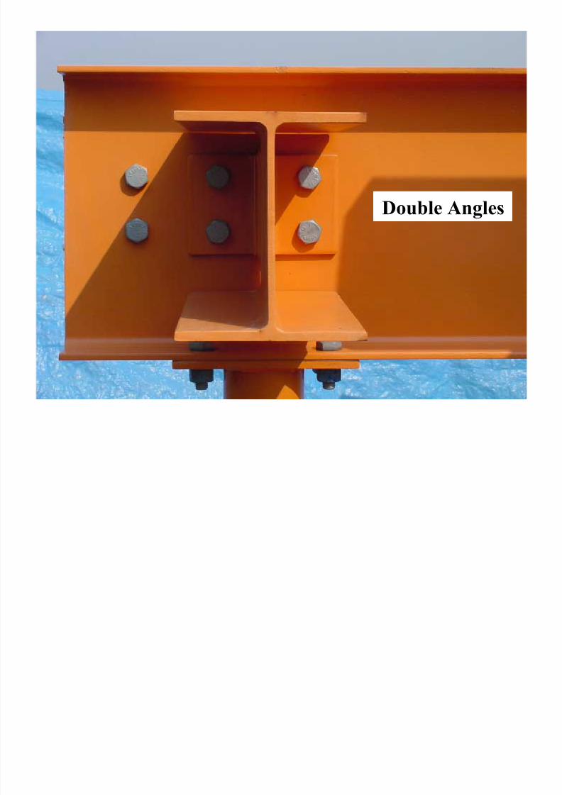
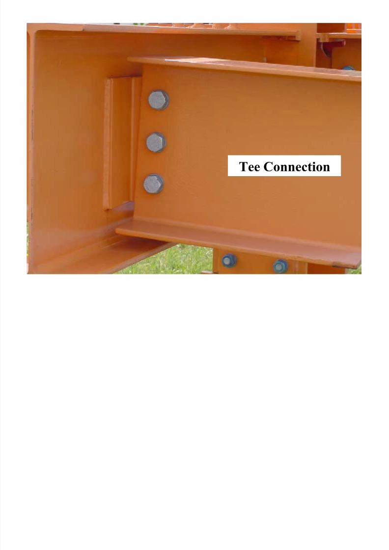
CONNECTION TYPES
• FRAMING (SHEAR) CONNECTIONSDouble Angles
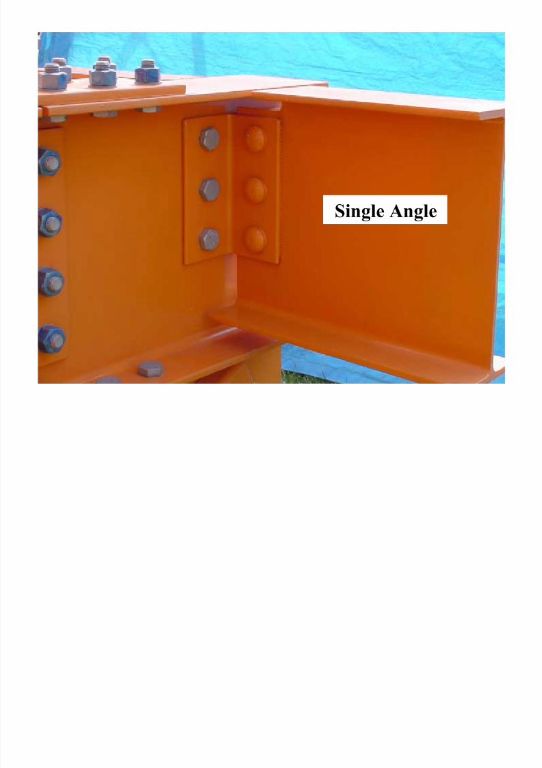
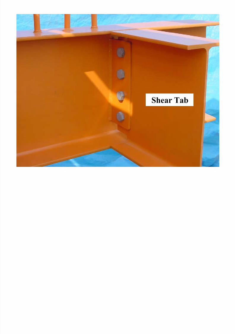
Single AngleShear Tab
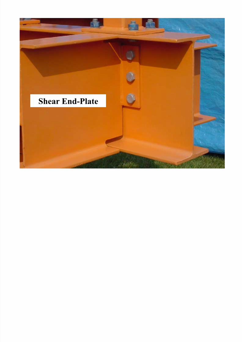
Shear End-Plate
Tee Connections
Seated
8/12/2019 Connections 1
http://slidepdf.com/reader/full/connections-1 9/67
9
Double Angles
8/12/2019 Connections 1
http://slidepdf.com/reader/full/connections-1 10/67
10
Single Angle
8/12/2019 Connections 1
http://slidepdf.com/reader/full/connections-1 11/67
11
Shear Tab
8/12/2019 Connections 1
http://slidepdf.com/reader/full/connections-1 12/67
12
Shear End-Plate
8/12/2019 Connections 1
http://slidepdf.com/reader/full/connections-1 13/67
8/12/2019 Connections 1
http://slidepdf.com/reader/full/connections-1 14/67
14
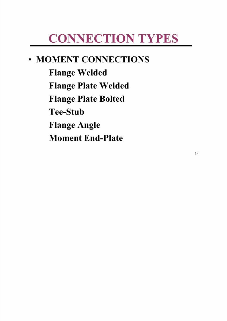
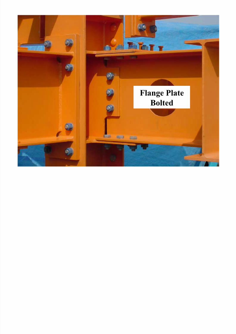
CONNECTION TYPES
• MOMENT CONNECTIONSFlange Welded
Flange Plate Welded
Flange Plate Bolted
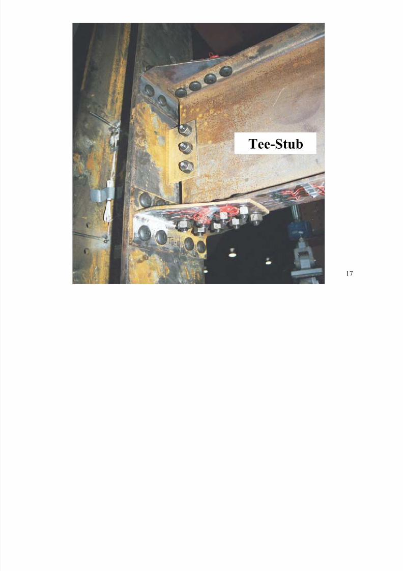
Tee-Stub
Flange Angle
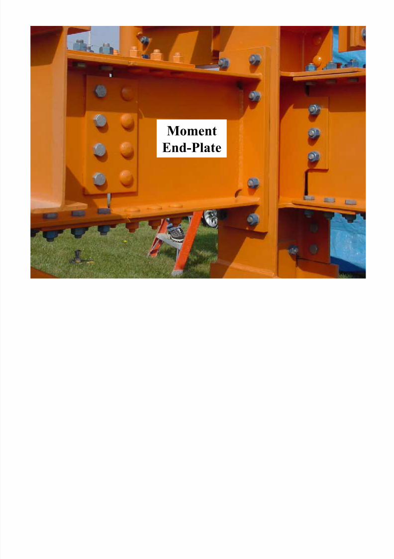
Moment End-Plate

8/12/2019 Connections 1
http://slidepdf.com/reader/full/connections-1 15/67
15
Flange Welded
8/12/2019 Connections 1
http://slidepdf.com/reader/full/connections-1 16/67
16
Flange PlateBolted
8/12/2019 Connections 1
http://slidepdf.com/reader/full/connections-1 17/67
17
Tee-Stub

8/12/2019 Connections 1
http://slidepdf.com/reader/full/connections-1 18/67
18
Flange Angle
8/12/2019 Connections 1
http://slidepdf.com/reader/full/connections-1 19/67
19
Moment
End-Plate
8/12/2019 Connections 1
http://slidepdf.com/reader/full/connections-1 20/67
20
CLASSIFICATION OFBEAM-TO COLUMN
CONNECTIONS
• Fully Restrained - FR
Flange Welded
Flange Plate Welded or Bolted
Tee-Stub
Moment End-Plate
8/12/2019 Connections 1
http://slidepdf.com/reader/full/connections-1 21/67
21
CLASSIFICATION OFBEAM-TO COLUMN
CONNECTIONS•Partially Restrained/Pinned - PR
Double Angles
Single Angle
Shear TabShear End-Plate
Seated
8/12/2019 Connections 1
http://slidepdf.com/reader/full/connections-1 22/67
22
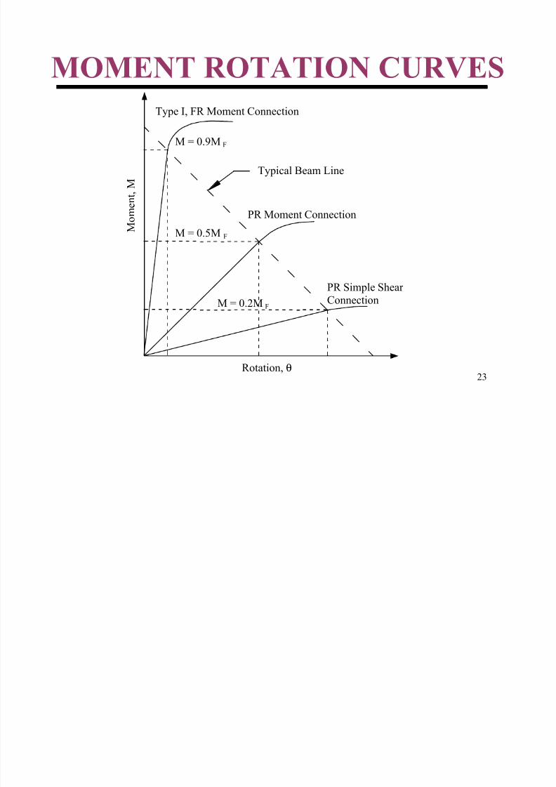
CLASSIFICATION OFBEAM-TO-COLUMN
CONNECTIONS
Classification: Depends on member length
and moment diagram andmagnitude of moment.
Example: Beam Line/Connection Curve
8/12/2019 Connections 1
http://slidepdf.com/reader/full/connections-1 23/67
23
MOMENT ROTATION CURVES
Rotation, θ
M
o m e n t , M
M = 0.9M
Typical Beam Line
Type I, FR Moment Connection
PR Moment Connection
PR Simple Shear
Connection
F
M = 0.5M F
M = 0.2M F
8/12/2019 Connections 1
http://slidepdf.com/reader/full/connections-1 24/67
24
SPECIFICATION
PROVISIONS
1999 LRFD Specification, Chapter J
Connection, Joints and Fasteners
1999 LRFD Specification, Chapter K Flanges and Webs with Concentrated Forces
LRFD Manual of Steel Construction3rd Edition: Parts 7 to 15
8/12/2019 Connections 1
http://slidepdf.com/reader/full/connections-1 25/67
25
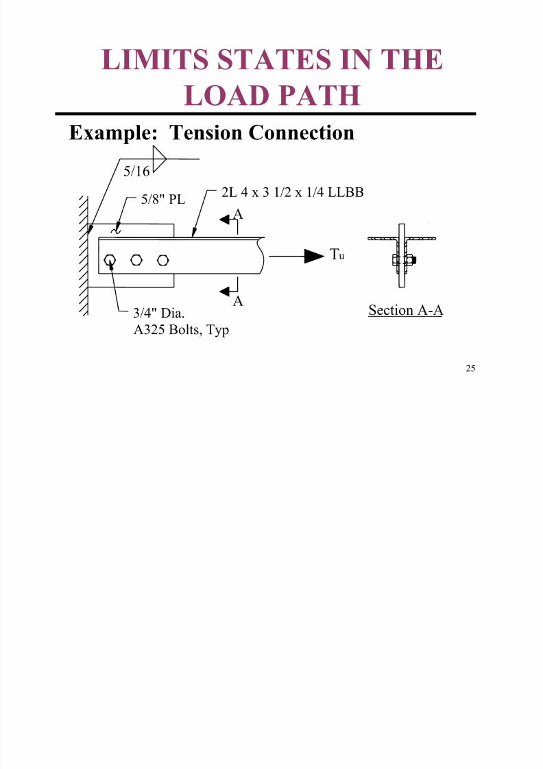
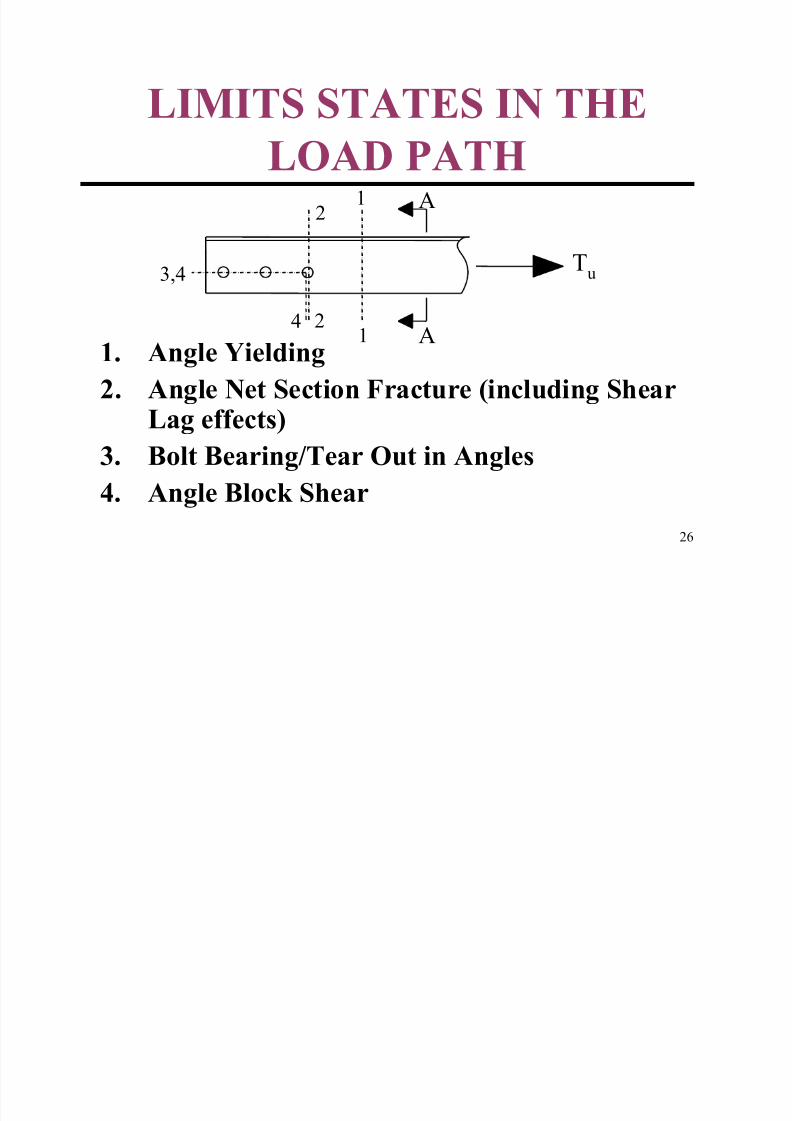
LIMITS STATES IN THE
LOAD PATH
Example: Tension Connection
5/16
5/8" PL2L 4 x 3 1/2 x 1/4 LLBB
Tu
3/4" Dia.
A325 Bolts, Typ
A
ASection A-A
8/12/2019 Connections 1
http://slidepdf.com/reader/full/connections-1 26/67
26
LIMITS STATES IN THELOAD PATH
1. Angle Yielding
2. Angle Net Section Fracture (including Shear
Lag effects)3. Bolt Bearing/Tear Out in Angles
4. Angle Block Shear
A
A
Tu
1
1
2
2
3,4
4
8/12/2019 Connections 1
http://slidepdf.com/reader/full/connections-1 27/67
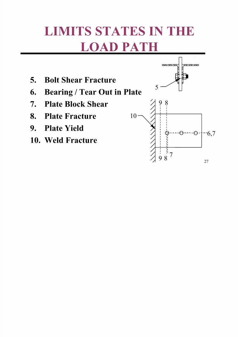
27
LIMITS STATES IN THELOAD PATH
5. Bolt Shear Fracture
6. Bearing / Tear Out in Plate
7. Plate Block Shear
8. Plate Fracture
9. Plate Yield10. Weld Fracture
5
7
6,7
8
8
9
9
10
8/12/2019 Connections 1
http://slidepdf.com/reader/full/connections-1 28/67
28
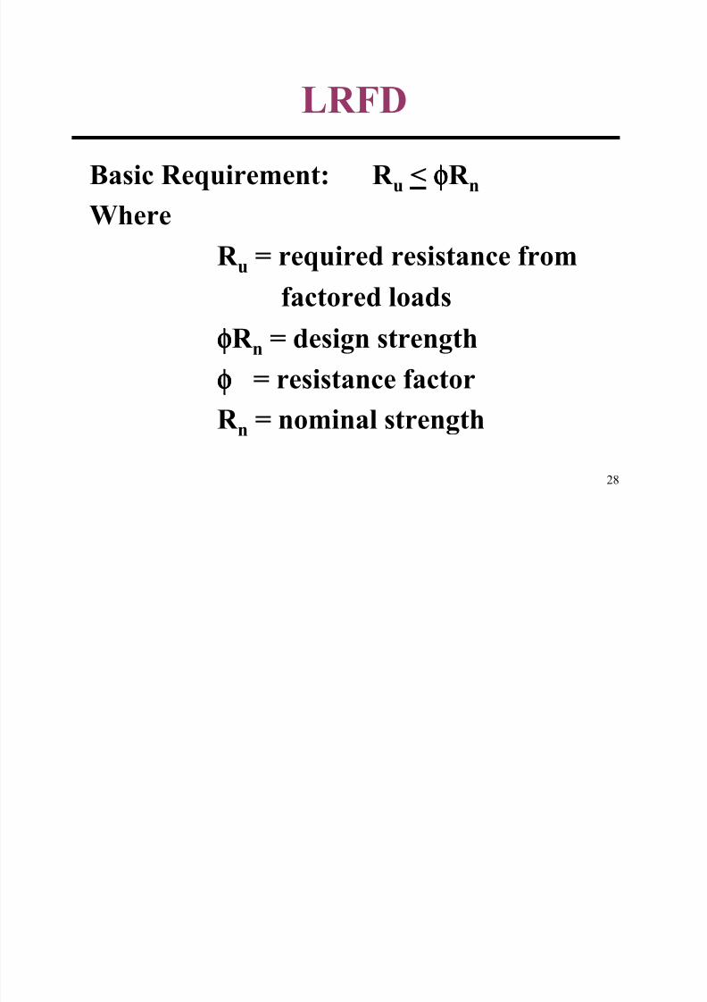
LRFD
Basic Requirement: R u < φφφφR n
Where
R u = required resistance from
factored loads
φφφφR n = design strength
φφφφ = resistance factorR n = nominal strength
8/12/2019 Connections 1
http://slidepdf.com/reader/full/connections-1 29/67
29
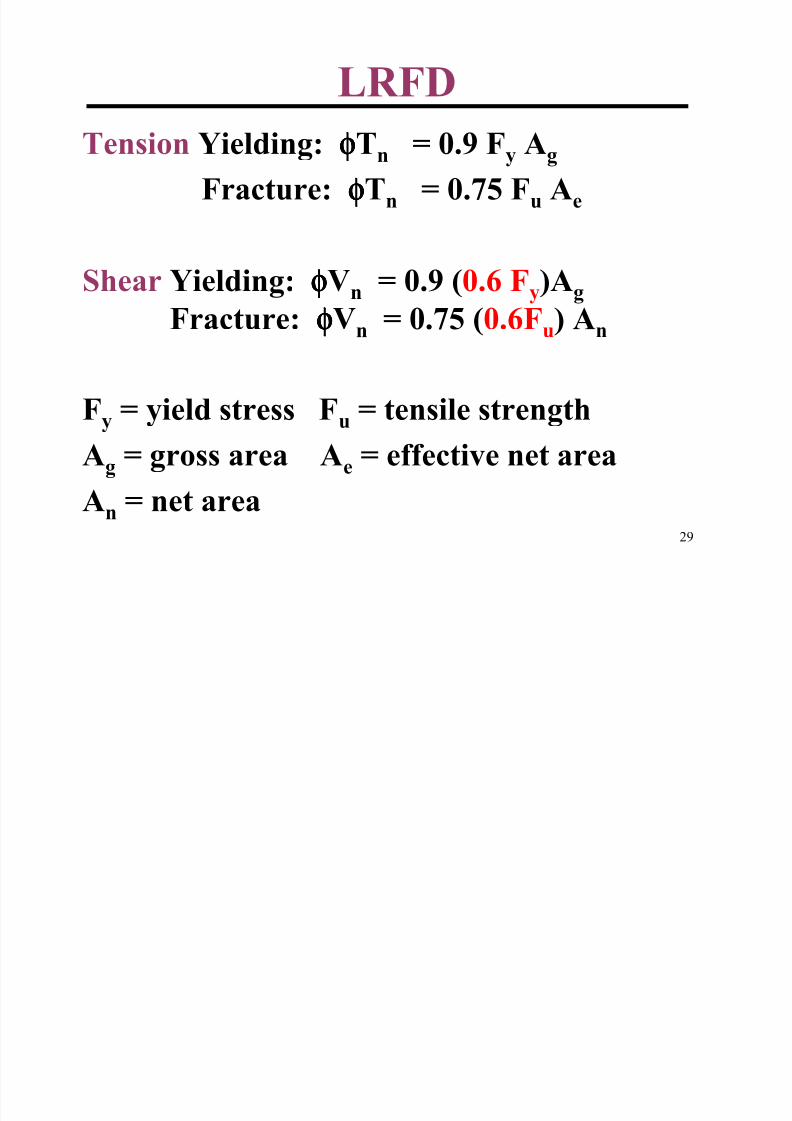
LRFD
Tension Yielding: φφφφTn = 0.9 Fy Ag
Fracture: φφφφTn = 0.75 Fu Ae
Shear Yielding: φφφφVn = 0.9 (0.6 Fy)Ag
Fracture: φφφφVn = 0.75 (0.6Fu) An
Fy = yield stress Fu = tensile strength
Ag = gross area Ae = effective net area
An = net area
8/12/2019 Connections 1
http://slidepdf.com/reader/full/connections-1 30/67
30
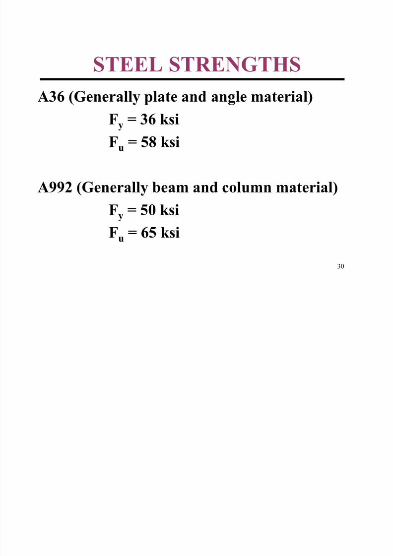
STEEL STRENGTHS
A36 (Generally plate and angle material)
Fy = 36 ksi
Fu = 58 ksi
A992 (Generally beam and column material)
Fy = 50 ksiFu = 65 ksi
8/12/2019 Connections 1
http://slidepdf.com/reader/full/connections-1 31/67
31
BASIC BOLT RELATED
LIMIT STATES
AND
DETAILING
8/12/2019 Connections 1
http://slidepdf.com/reader/full/connections-1 32/67
32
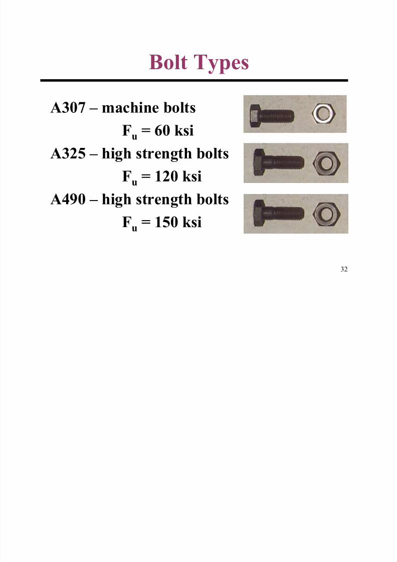
Bolt Types
A307 – machine boltsFu = 60 ksi
A325 – high strength bolts
Fu = 120 ksi
A490 – high strength bolts
Fu = 150 ksi
8/12/2019 Connections 1
http://slidepdf.com/reader/full/connections-1 33/67
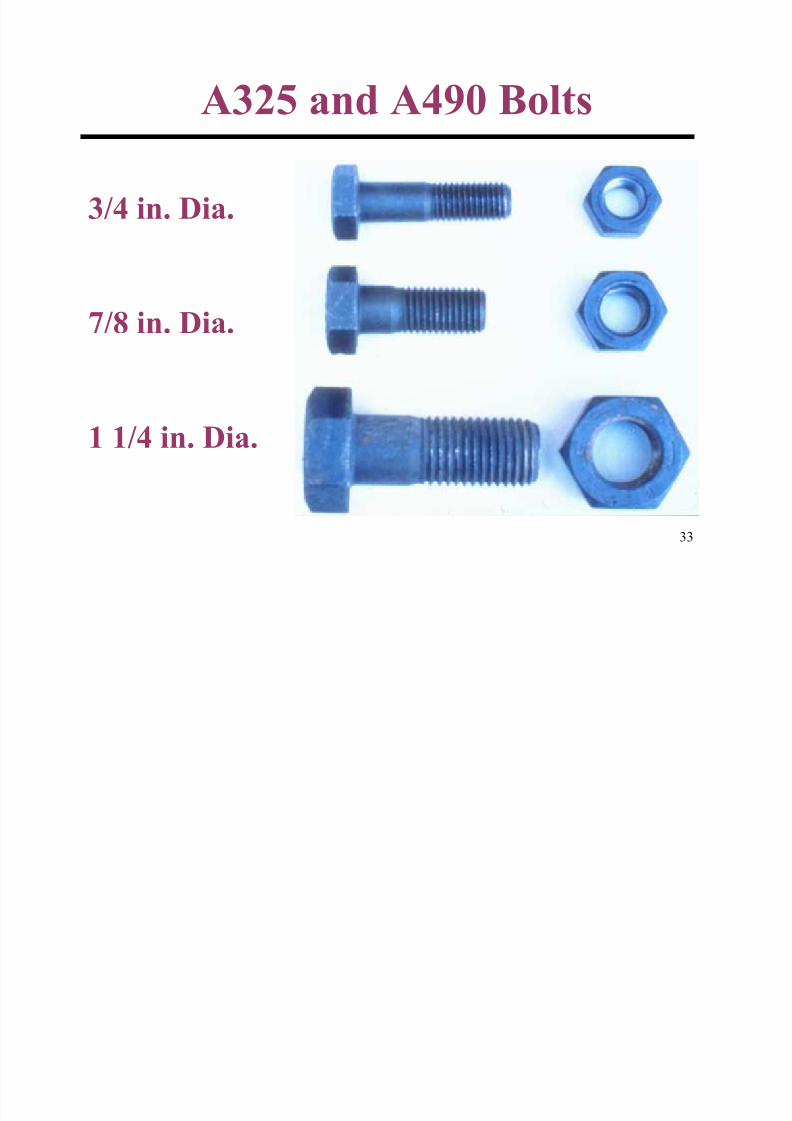
33
3/4 in. Dia.
7/8 in. Dia.
1 1/4 in. Dia.
A325 and A490 Bolts
8/12/2019 Connections 1
http://slidepdf.com/reader/full/connections-1 34/67
34
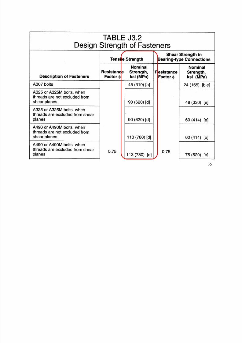
Bolt Tension Strength
(LRFD Table J3.2)
Design tension strength of one Bolt, φφφφrt :φφφφ = 0.75
rt = Ft Ab
Ab = nominal bolt area
Ft = nominal strength from Table J3.2
φφφφrt = 0.75 Ft Ab = design tension strength
Note: reduced area through threads is
accounted for in Ft
.
8/12/2019 Connections 1
http://slidepdf.com/reader/full/connections-1 35/67
35
8/12/2019 Connections 1
http://slidepdf.com/reader/full/connections-1 36/67
36
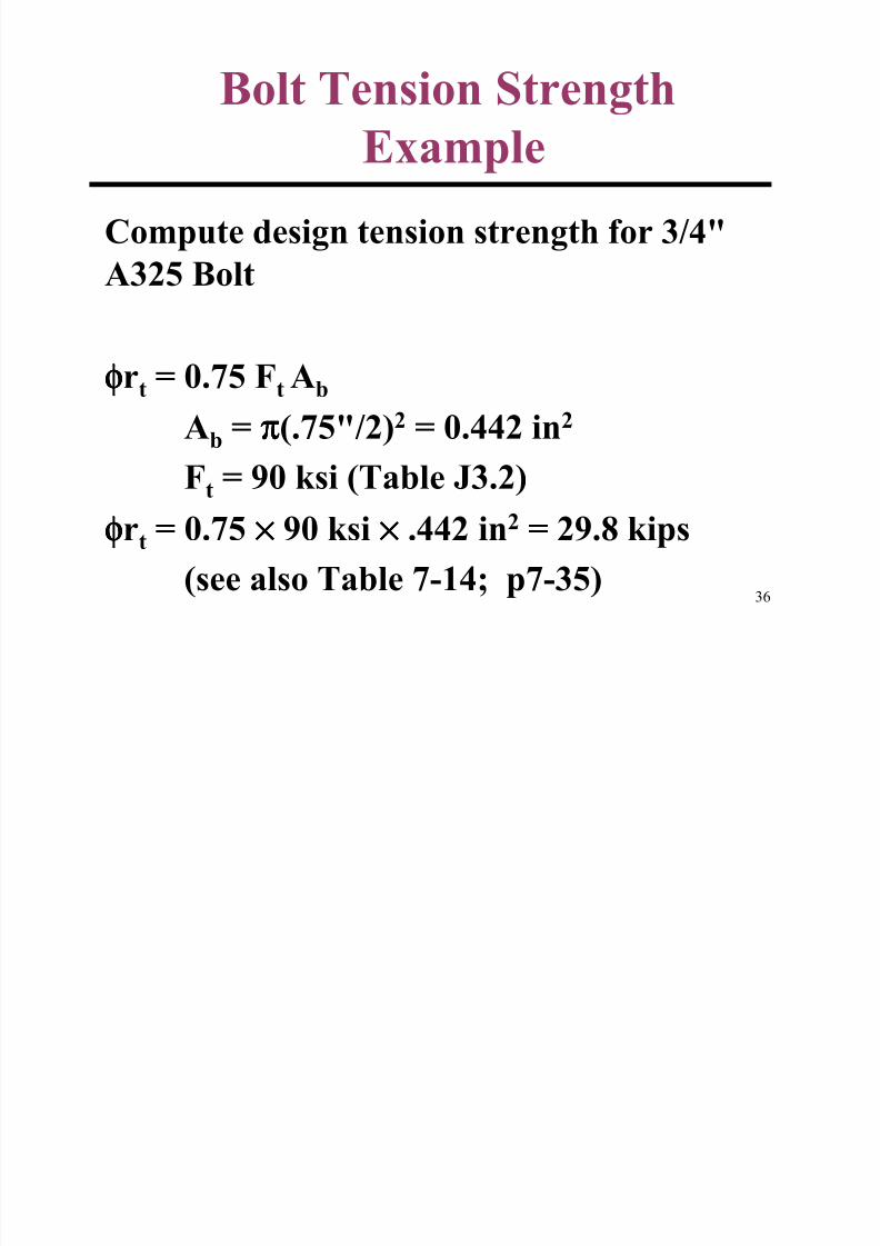
Bolt Tension Strength
Example
Compute design tension strength for 3/4"A325 Bolt
φφφφrt = 0.75 Ft Ab
Ab = ππππ(.75"/2)2 = 0.442 in2
Ft = 90 ksi (Table J3.2)φφφφrt = 0.75 ×××× 90 ksi ×××× .442 in2 = 29.8 kips
(see also Table 7-14; p7-35)
8/12/2019 Connections 1
http://slidepdf.com/reader/full/connections-1 37/67
37
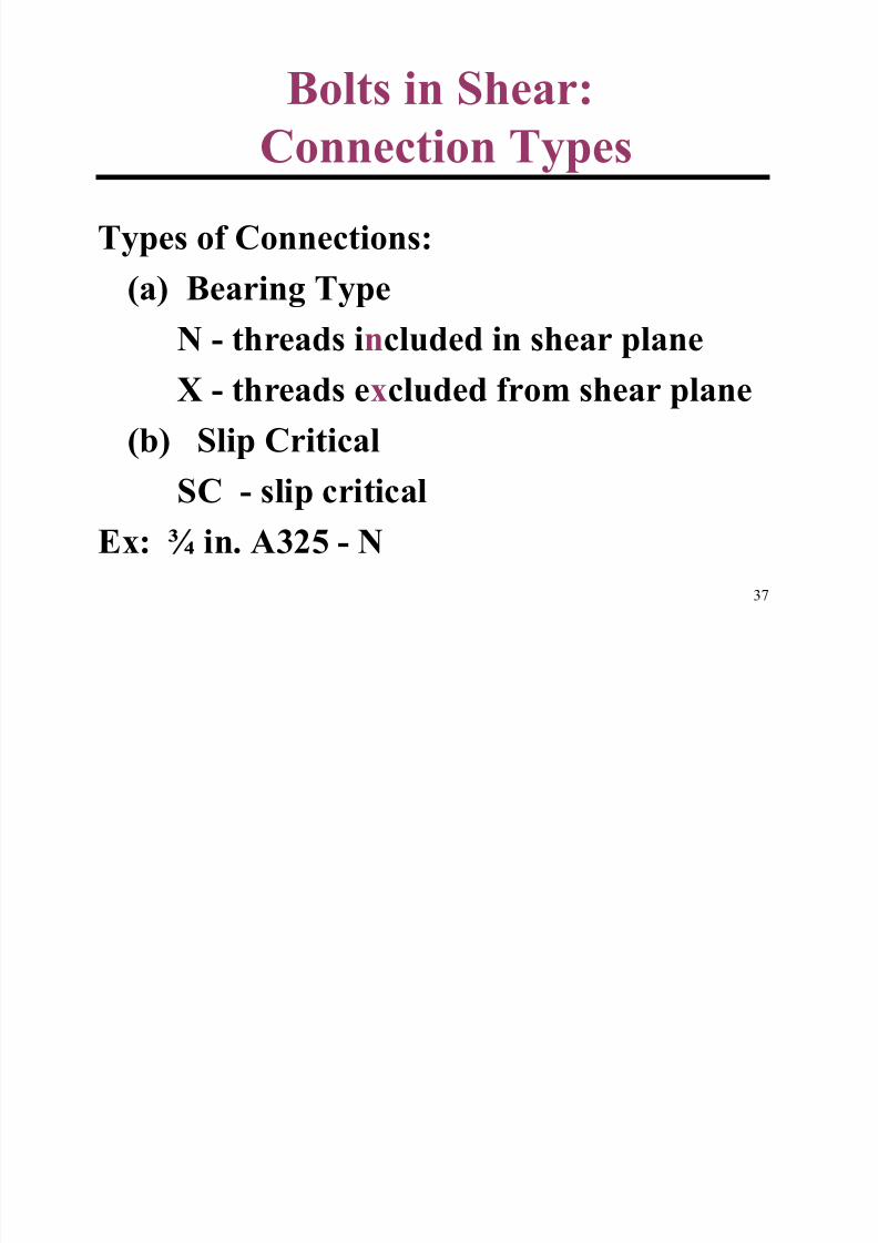
Bolts in Shear:
Connection Types
Types of Connections:(a) Bearing Type
N - threads included in shear plane
X - threads excluded from shear plane
(b) Slip Critical
SC - slip critical
Ex: ¾ in. A325 - N
B lt Sh St th
8/12/2019 Connections 1
http://slidepdf.com/reader/full/connections-1 38/67
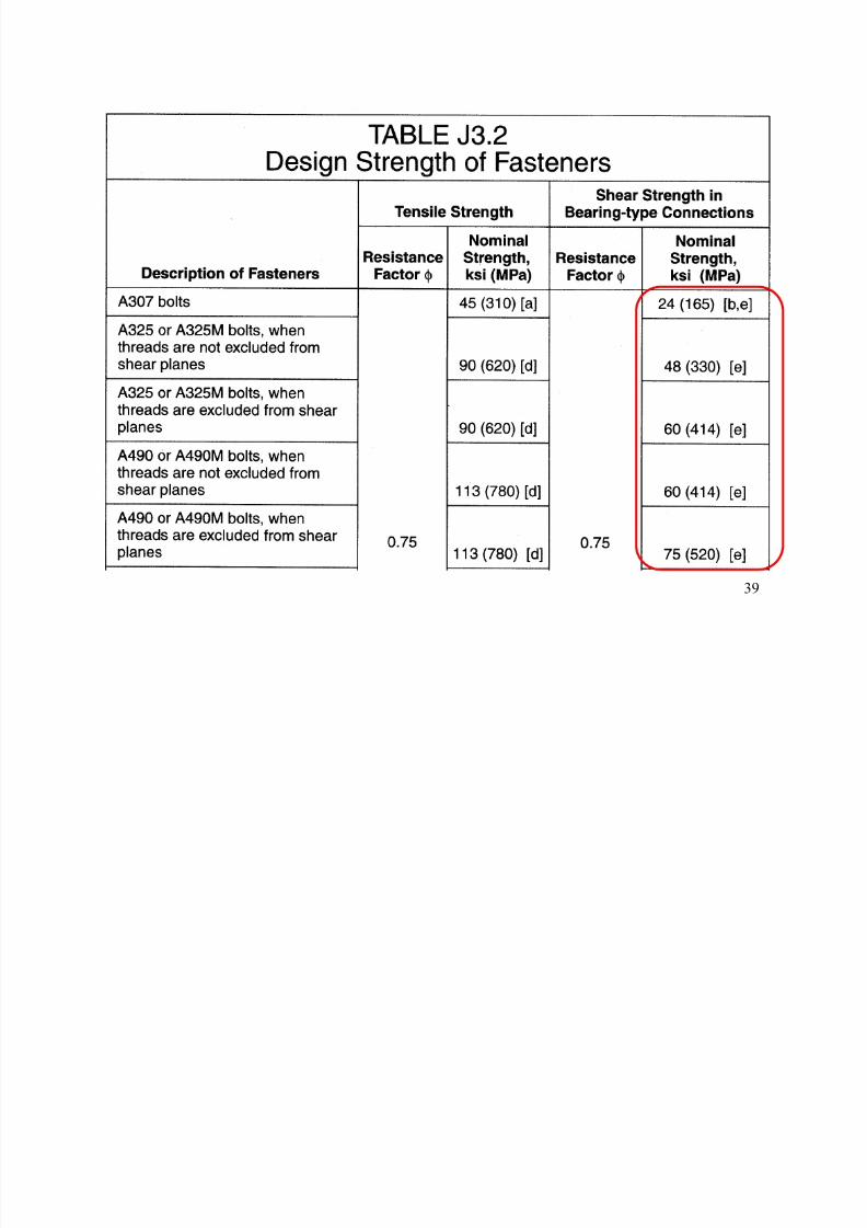
38
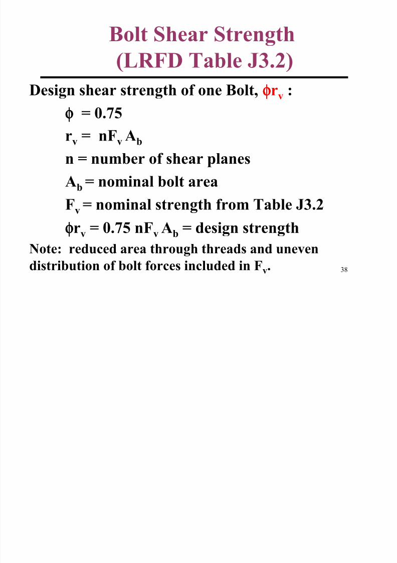
Bolt Shear Strength
(LRFD Table J3.2)Design shear strength of one Bolt, φφφφrv :
φφφφ = 0.75
rv = nFv Ab
n = number of shear planesAb = nominal bolt area
Fv = nominal strength from Table J3.2
φφφφrv = 0.75 nFv Ab = design strength
Note: reduced area through threads and uneven
distribution of bolt forces included in Fv.
8/12/2019 Connections 1
http://slidepdf.com/reader/full/connections-1 39/67
39
8/12/2019 Connections 1
http://slidepdf.com/reader/full/connections-1 40/67
40
Table J3.2 Continued
8/12/2019 Connections 1
http://slidepdf.com/reader/full/connections-1 41/67
41
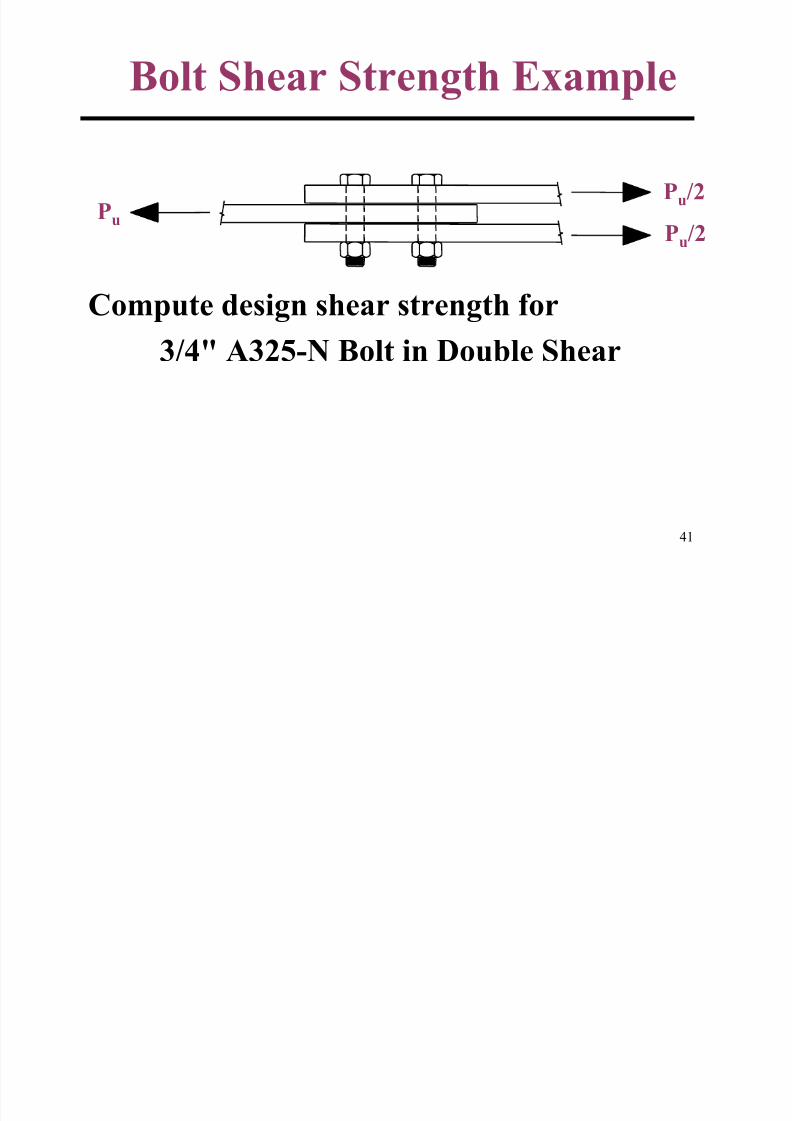
Bolt Shear Strength Example
Pu
Pu/2
Pu/2
Compute design shear strength for
3/4" A325-N Bolt in Double Shear
B lt Sh St th E l
8/12/2019 Connections 1
http://slidepdf.com/reader/full/connections-1 42/67
42
Bolt Shear Strength Example
(cont)
φφφφrv = 0.75 nFv Ab
n = 2
Ab = ππππ(.75"/2)2 = 0.442 in2
Fv = 48 ksi (Table J3.2)
φφφφrv = 0.75 ×××× 2 ×××× 48 ksi ×××× .442 in2 = 31.8 kips
(see also Table 7-10; p7-33)
8/12/2019 Connections 1
http://slidepdf.com/reader/full/connections-1 43/67
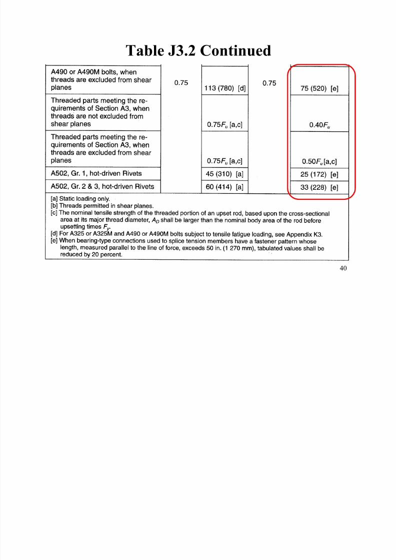
43
Bolts: Connection Length Effect
Table J3.2 Footnote [e]
When bearing-type connections used to
splice tension members have a fastener
pattern whose length, measured parallel to
the line of force, exceeds 50 in., tabulated
values shall be reduced by 20 percent.
8/12/2019 Connections 1
http://slidepdf.com/reader/full/connections-1 44/67
44
Slip Critical (-SC) Connections
• In Slip-Critical (SC) connections, slip isconsidered to be a limit state (serviceability or
strength)
• Slip checked using either factored load (slip isstrength limit state) or service loads (slip is
serviceability limit state)
• Slip-critical connections require pretensionedbolts and control of faying surface
8/12/2019 Connections 1
http://slidepdf.com/reader/full/connections-1 45/67
45
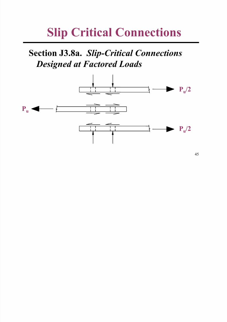
Slip Critical ConnectionsSection J3.8a. Slip-Critical Connections
Designed at Factored Loads
Pu
Pu/2
Pu/2
8/12/2019 Connections 1
http://slidepdf.com/reader/full/connections-1 46/67
46
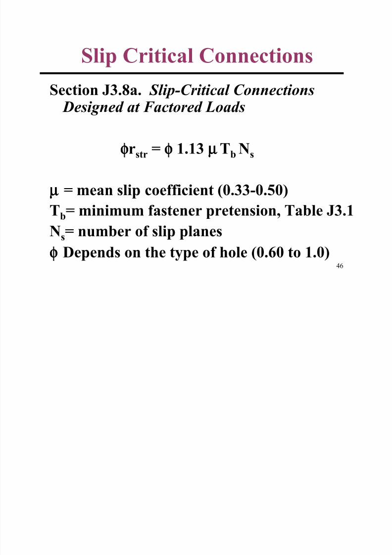
Slip Critical ConnectionsSection J3.8a. Slip-Critical Connections
Designed at Factored Loads
φφφφrstr = φφφφ 1.13 µµµµTb Ns
µµµµ = mean slip coefficient (0.33-0.50)
Tb= minimum fastener pretension, Table J3.1Ns= number of slip planes
φφφφ Depends on the type of hole (0.60 to 1.0)
8/12/2019 Connections 1
http://slidepdf.com/reader/full/connections-1 47/67
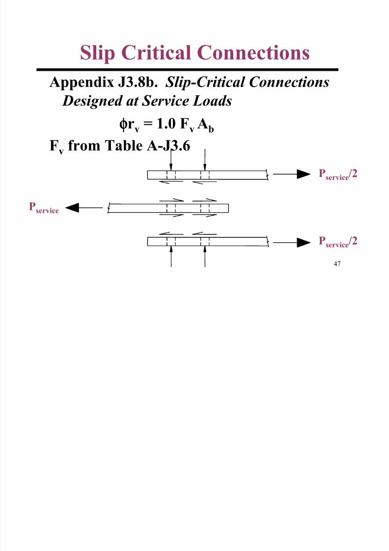
47
Slip Critical ConnectionsAppendix J3.8b. Slip-Critical Connections
Designed at Service Loads
φφφφrv = 1.0 Fv Ab
Fv from Table A-J3.6
Pservice
Pservice/2
Pservice/2
Bolts: Combined Shear and
8/12/2019 Connections 1
http://slidepdf.com/reader/full/connections-1 48/67
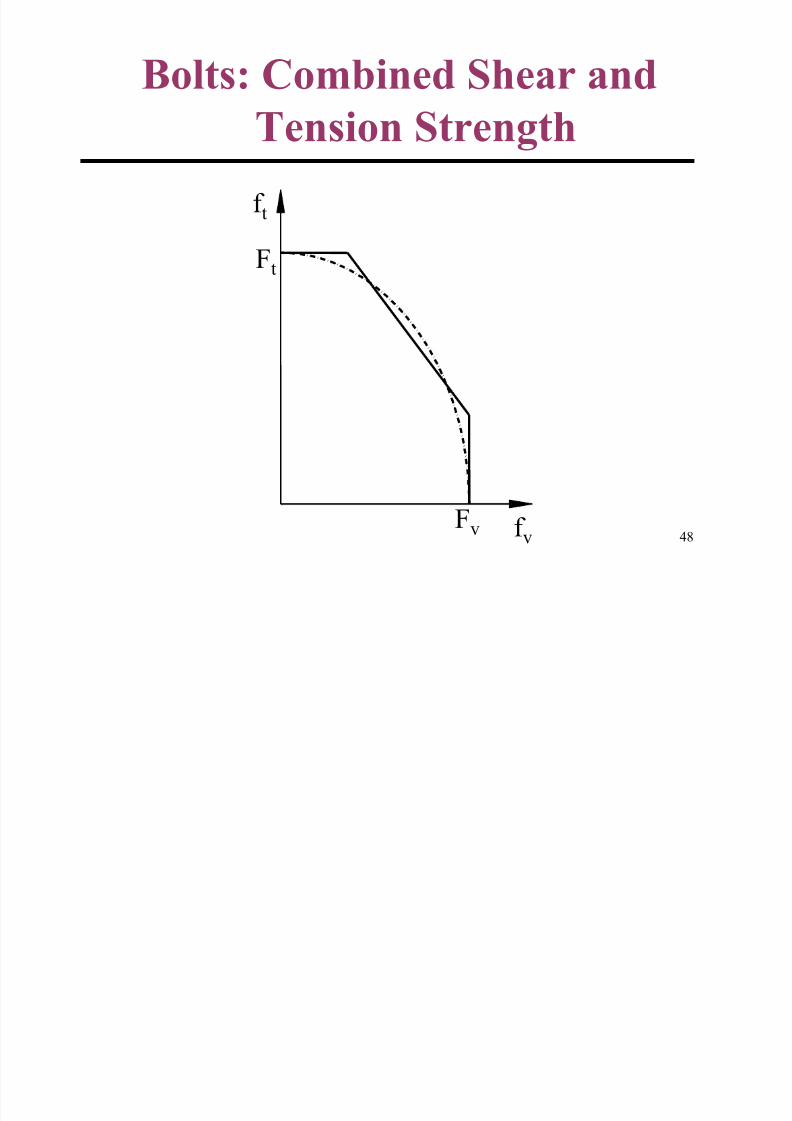
48
Bolts: Combined Shear and
Tension Strength
f t
f v
Ft
Fv
8/12/2019 Connections 1
http://slidepdf.com/reader/full/connections-1 49/67
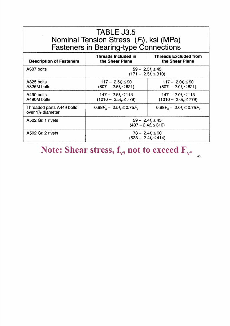
49
Note: Shear stress, f v, not to exceed Fv.
8/12/2019 Connections 1
http://slidepdf.com/reader/full/connections-1 50/67
50
Bolt HolesHole Types and Dimensions (Table J3.3):
• Standard (Std.) db + 1/16 in.
• Oversized (OVS)
• Short Slots (SS)
• Long Slots (LS)
(Standard Hole is default for these notes)
8/12/2019 Connections 1
http://slidepdf.com/reader/full/connections-1 51/67
51
8/12/2019 Connections 1
http://slidepdf.com/reader/full/connections-1 52/67
52
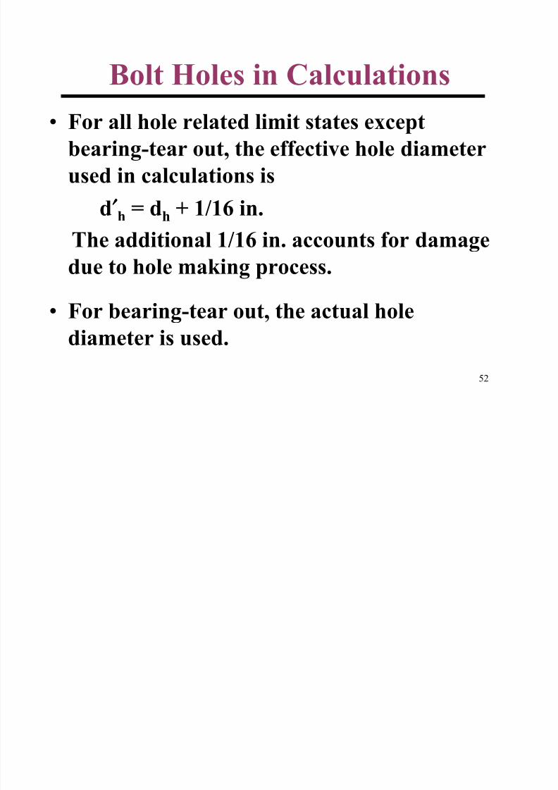
Bolt Holes in Calculations• For all hole related limit states except
bearing-tear out, the effective hole diameterused in calculations is
d′′′′h = dh + 1/16 in.
The additional 1/16 in. accounts for damagedue to hole making process.
• For bearing-tear out, the actual holediameter is used.
8/12/2019 Connections 1
http://slidepdf.com/reader/full/connections-1 53/67
53
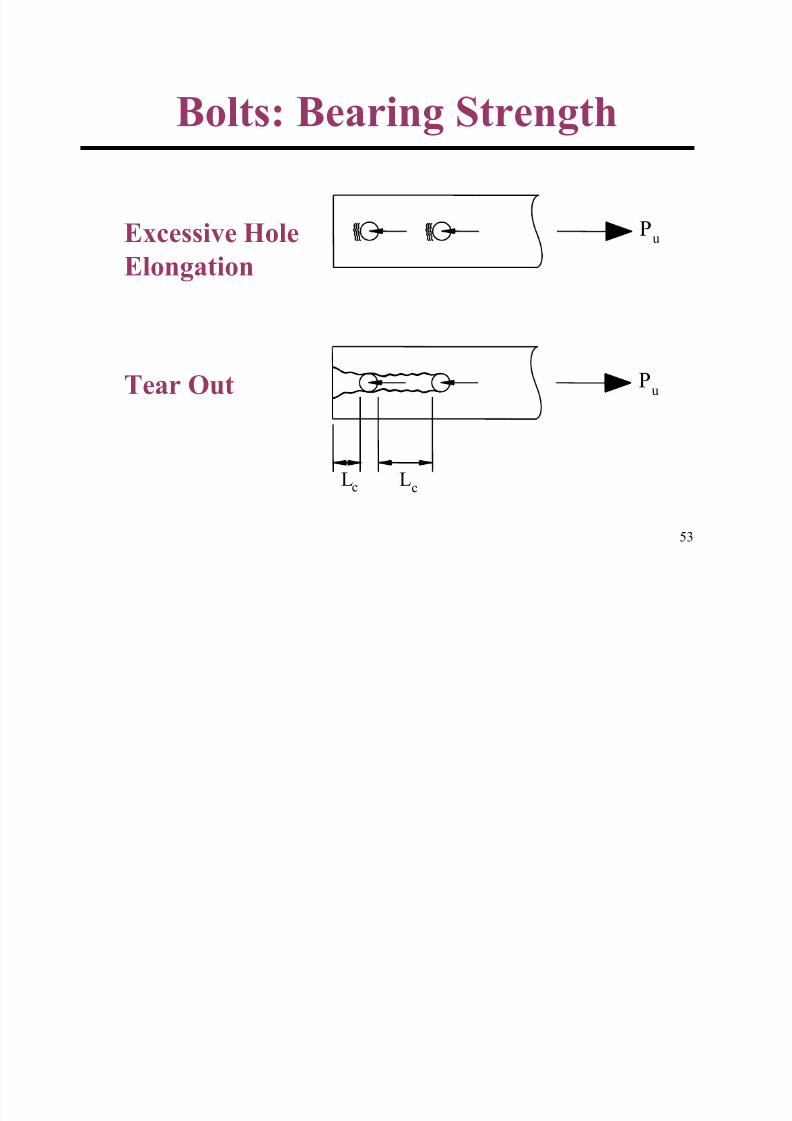
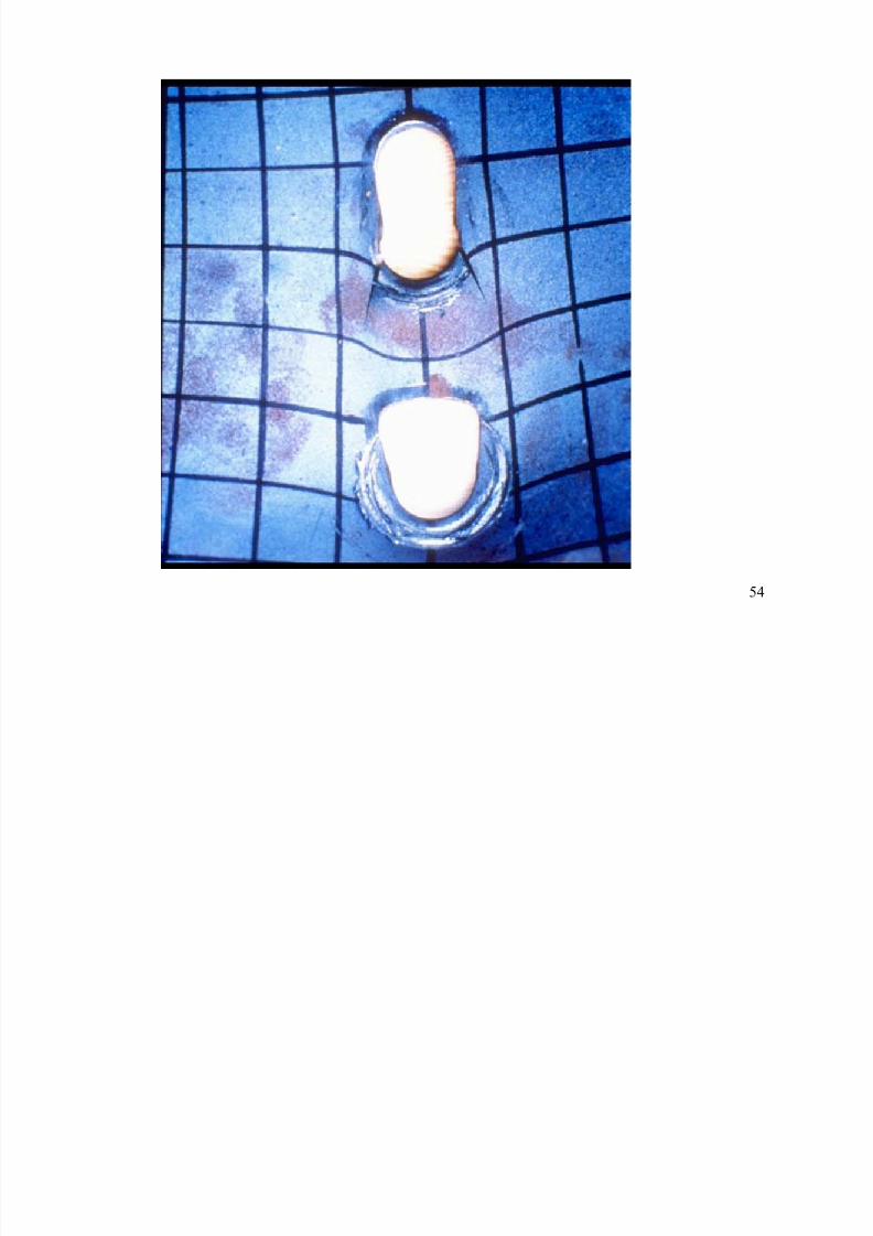
Bolts: Bearing Strength
Pu
Lc Lc
Pu
Excessive HoleElongation
Tear Out
8/12/2019 Connections 1
http://slidepdf.com/reader/full/connections-1 54/67
54
8/12/2019 Connections 1
http://slidepdf.com/reader/full/connections-1 55/67
55
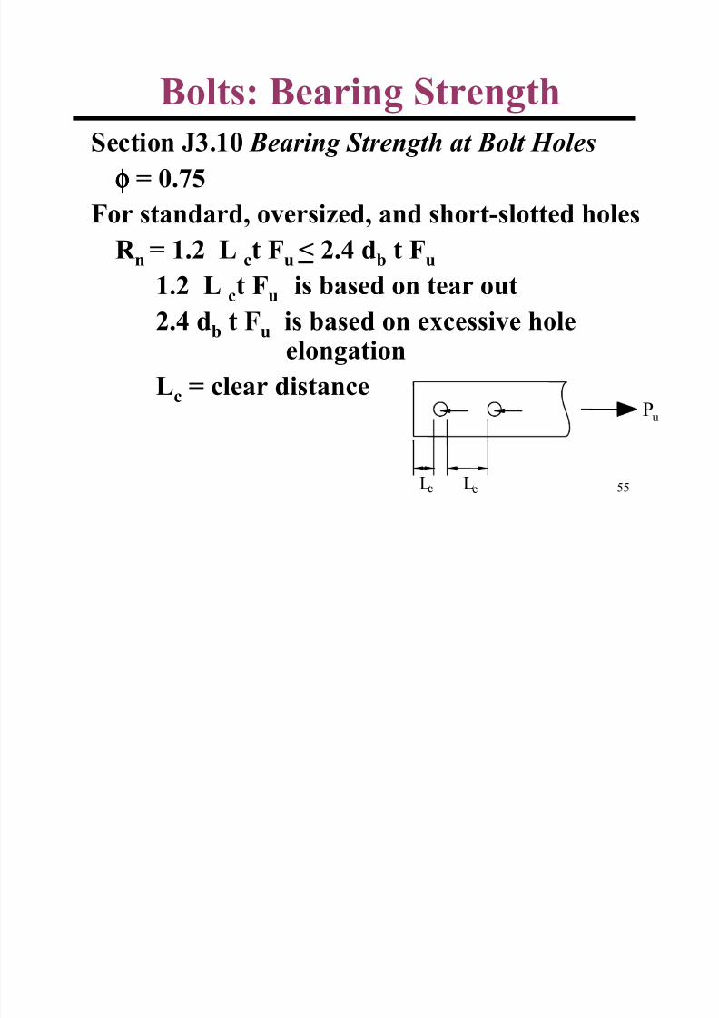
Bolts: Bearing StrengthSection J3.10 Bearing Strength at Bolt Holes
φφφφ = 0.75
For standard, oversized, and short-slotted holes
R n = 1.2 L ct Fu < 2.4 db t Fu
1.2 Lc
t Fu
is based on tear out
2.4 db t Fu is based on excessive holeelongation
Lc = clear distance
Lc Lc
Pu
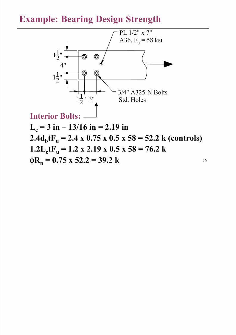
Example: Bearing Design Strength
8/12/2019 Connections 1
http://slidepdf.com/reader/full/connections-1 56/67
56
Interior Bolts:
Lc
= 3 in – 13/16 in = 2.19 in
2.4dbtFu = 2.4 x 0.75 x 0.5 x 58 = 52.2 k (controls)
1.2LctFu = 1.2 x 2.19 x 0.5 x 58 = 76.2 k
φφφφR n = 0.75 x 52.2 = 39.2 k
3"112"
4"
112"
112"
PL 1/2" x 7"
A36, Fu = 58 ksi
3/4" A325-N Bolts
Std. Holes
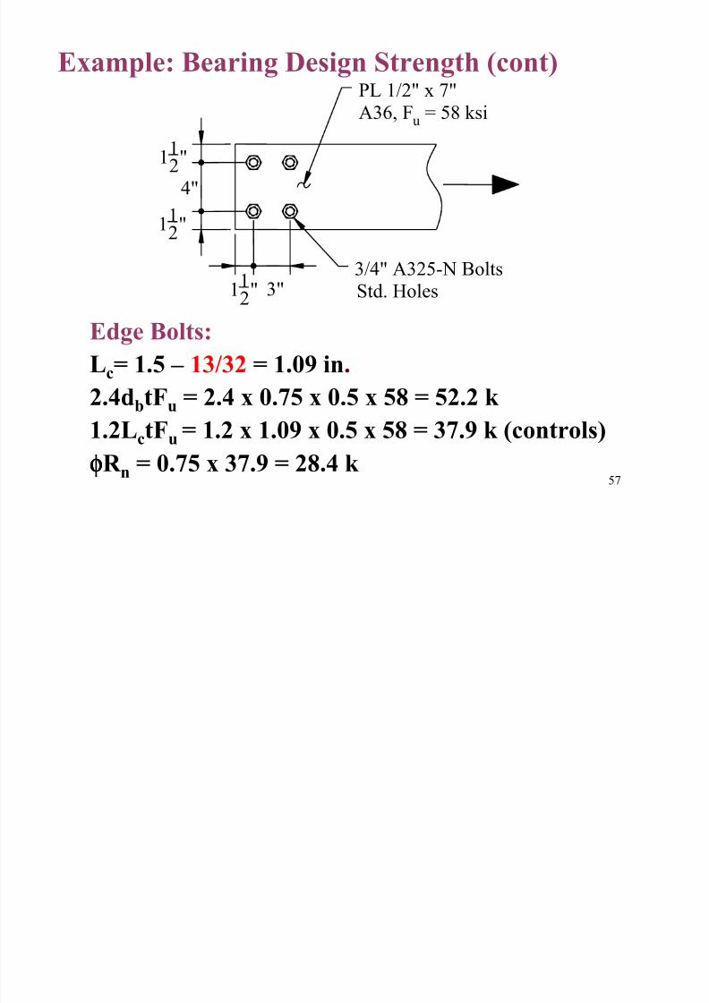
Example: Bearing Design Strength (cont)
8/12/2019 Connections 1
http://slidepdf.com/reader/full/connections-1 57/67
57
p g g g ( )
Edge Bolts:
Lc= 1.5 – 13/32 = 1.09 in.
2.4dbtFu = 2.4 x 0.75 x 0.5 x 58 = 52.2 k 1.2LctFu = 1.2 x 1.09 x 0.5 x 58 = 37.9 k (controls)
φφφφR n = 0.75 x 37.9 = 28.4 k
3"1
1
2"
4"
112"
112"
PL 1/2" x 7"
A36, Fu = 58 ksi
3/4" A325-N Bolts
Std. Holes
Bolts: Minimum Spacing and
8/12/2019 Connections 1
http://slidepdf.com/reader/full/connections-1 58/67
58
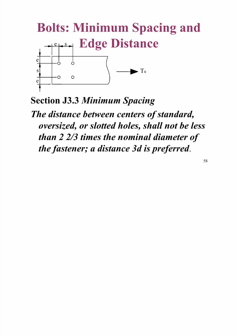
Bolts: Minimum Spacing and
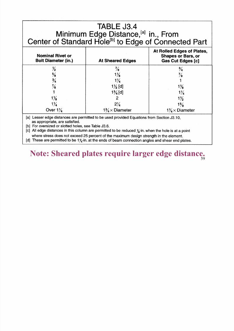
Edge Distance
Section J3.3 Minimum Spacing The distance between centers of standard,
oversized, or slotted holes, shall not be less
than 2 2/3 times the nominal diameter of
the fastener; a distance 3d is preferred .
Tu
e s
s
e
e
8/12/2019 Connections 1
http://slidepdf.com/reader/full/connections-1 59/67
59Note: Sheared plates require larger edge distance.
8/12/2019 Connections 1
http://slidepdf.com/reader/full/connections-1 60/67
60
BASIC WELD RELATED
LIMIT STATES
AND
DETAILING
8/12/2019 Connections 1
http://slidepdf.com/reader/full/connections-1 61/67
61
Weld FractureWelds J2.4. Design Strength
Design Strength = φφφφ R n
= φφφφ Fw
Aw.
For Fillet Welds
φ = 0.75Fw = 0.60 FEXX
FEXX
= electrode tensile strength, ksi
8/12/2019 Connections 1
http://slidepdf.com/reader/full/connections-1 62/67
62
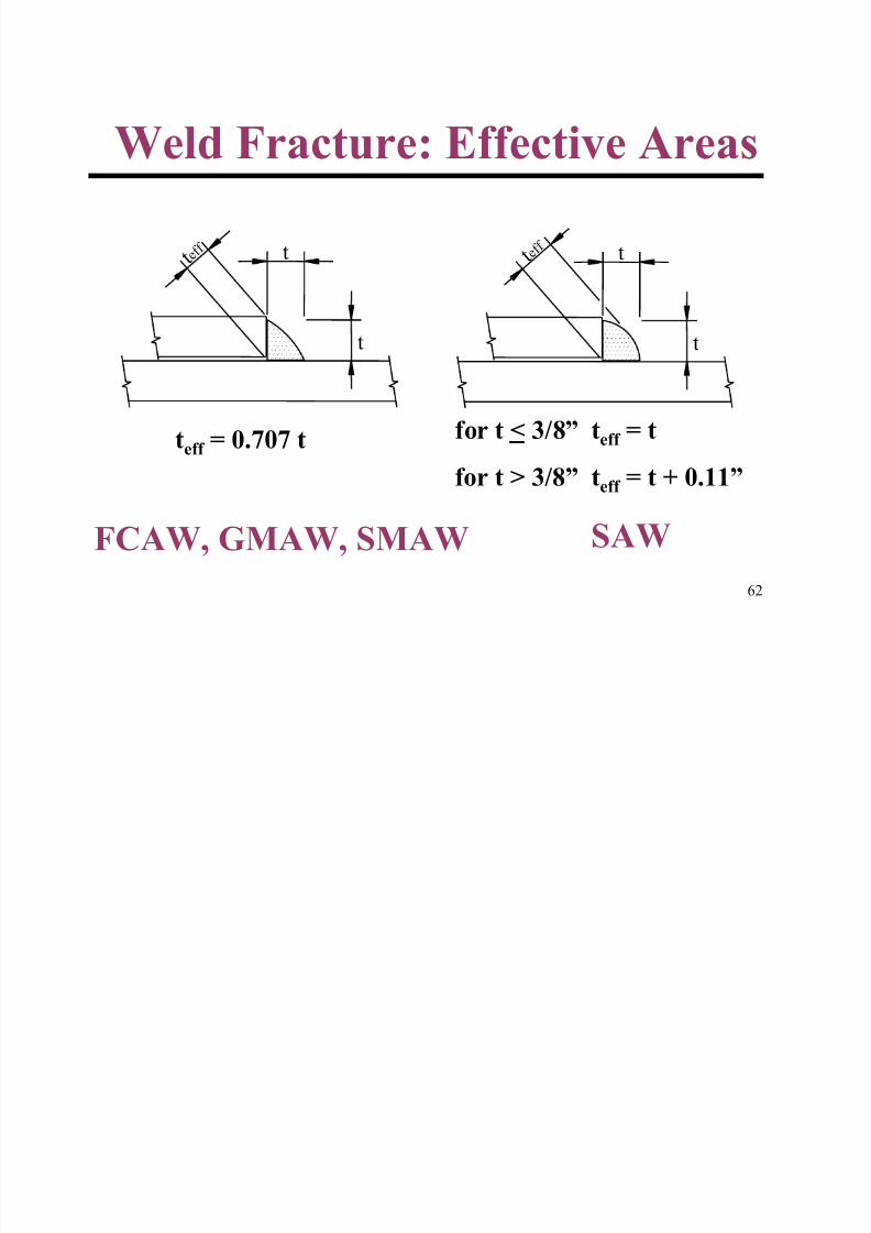
Weld Fracture: Effective Areas
FCAW, GMAW, SMAW SAW
t e f f
t
t t e f f
t
t
teff = 0.707 t for t < 3/8” teff = t
for t > 3/8” teff = t + 0.11”
Weld Fracture
8/12/2019 Connections 1
http://slidepdf.com/reader/full/connections-1 63/67
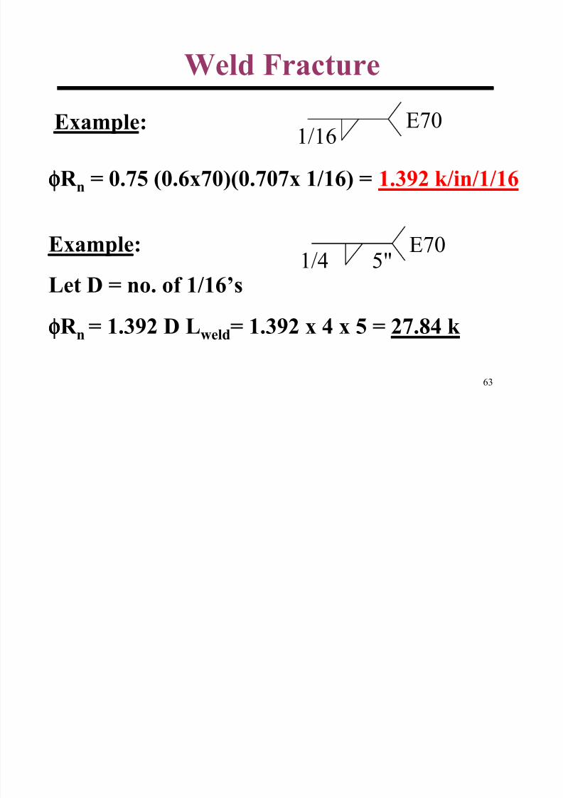
63
φφφφR n = 0.75 (0.6x70)(0.707x 1/16) = 1.392 k/in/1/16
Example:
Let D = no. of 1/16’s
φφφφR n = 1.392 D Lweld= 1.392 x 4 x 5 = 27.84 k
Weld Fracture
Example: E701/16
5"E70
1/4
8/12/2019 Connections 1
http://slidepdf.com/reader/full/connections-1 64/67
64
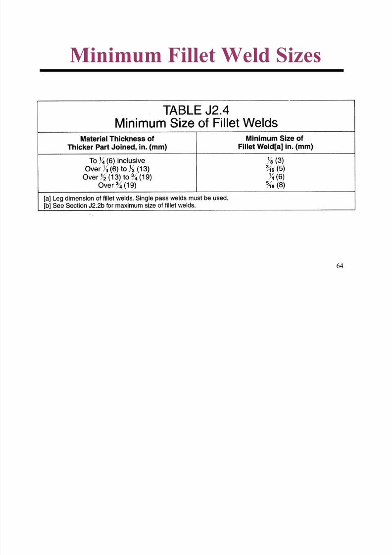
Minimum Fillet Weld Sizes
8/12/2019 Connections 1
http://slidepdf.com/reader/full/connections-1 65/67
65
Maximum Fillet Weld Size
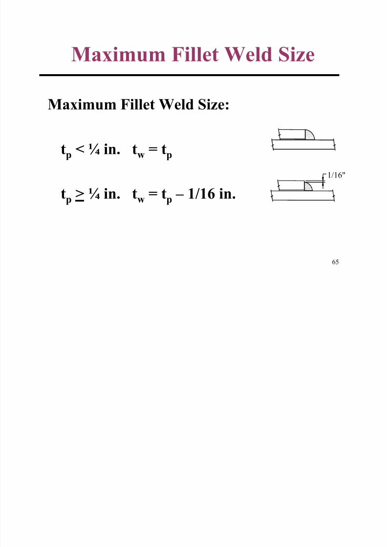
Maximum Fillet Weld Size:
tp < ¼ in. tw = tp
tp > ¼ in. tw = tp – 1/16 in.
1/16"
8/12/2019 Connections 1
http://slidepdf.com/reader/full/connections-1 66/67
66
Base Metal Strength at Weld
Section J4.1 Shear Rupture StrengthThe design rupture strength for the limit
state of rupture along a shear failure path
in the affected elements of connectedmembers shall be taken as
φφφφR n = 0.75 (0.6 Fu Anw)
E ample: Determine φφφφP for Welds
8/12/2019 Connections 1
http://slidepdf.com/reader/full/connections-1 67/67
67
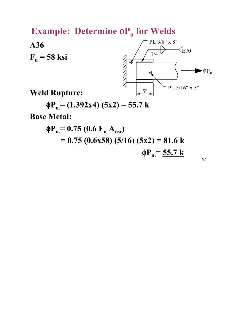
Example: Determine φφφφPn
for Welds
A36
Fu = 58 ksi
Weld Rupture:
φφφφPn.= (1.392x4) (5x2) = 55.7 k
Base Metal:
φφφφPn.= 0.75 (0.6 Fu Anw)= 0.75 (0.6x58) (5/16) (5x2) = 81.6 k
φφφφPn.= 55.7 k
φPn
E701/4
PL 5/16" x 5"
PL 3/8" x 8"
5"


![Bolted Connections[1]](https://img.pdfslide.net/doc/110x75/54e7f8c84a7959704f8b46b8/bolted-connections1.jpg)