Embed Size (px)
Citation preview
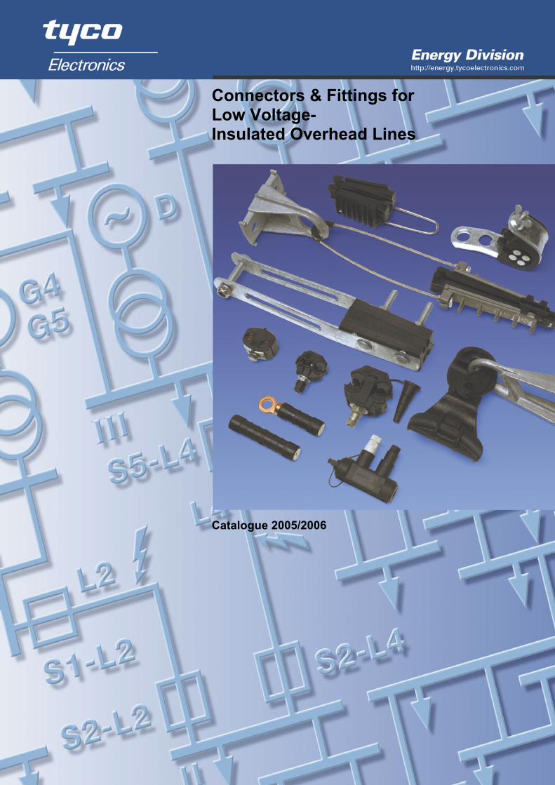
Connectors & Fittings for Low Voltage- Insulated Overhead Lines Catalogue 2005/2006
- 1 -
Connectors & Fittings for LV - Insulated Overhead Lines (Aerial Bundled Conductor Systems) Content Page Introduction to LV-ABC lines 2 Tap-off connectors • Insulation piercing connectors for main, service and lighting lines 4 • Insulation piercing connectors for connections to bare overhead 6 • Insulation piercing connectors for connections to cables 7 • Parallel groove clamps for bare neutral messenger and grounding 8
(Alu/Alu, Alu/Cu, Cu/Cu connectors) • Compression branch connectors and sealing kit 9
Inline connectors and lugs • Waterproof pre-insulated connectors for service cables 10 • Waterproof pre-insulated hexagonal compression connectors 12 • Waterproof pre-insulated hexagonal compression lugs 13 • Bare full- and non-tension DIN- compression connectors 14 • Bare mechanical lugs with heat-shrinkable tubing 15 • Bare non-tension mechanical connectors 16
Connection and insulation accessories • Breakouts, tubing, end caps, repair sleeves, repair tape 17-21 • Surge arrester, fuse link, earthing adapter 22-25
Anchoring and suspension of LV-ABC lines • For service lines and cables 26-27 • For self supporting lines 28-29 • For lines with insulated neutral messenger 30-31 • For lines with bare neutral messenger 32-33 • Wall mounted saddles and cable ties 34 • Steel straps and protection devices 35 • Hooks, brackets and bolts 36
Installation tools and equipment • For setting up LV-ABC lines 38-39 • For installing stainless steel strap and cable ties 40 • For connecting LV-ABC lines 41 • For compression connections of LV-ABC lines 42-43
Dimensions of LV-ABC cables according to HD 626 • For self supporting lines 44 • For lines with insulated neutral messenger 45 • For lines with bare neutral messenger 46
- 2 -
Low Voltage Insulated Overhead Lines (LV - Aerial Bundled Conductor System)
Tyco Electronics Energy Division was one of the first to pioneer the connection, anchoring and suspension of low-voltage insulated overhead systems since its first installations in the mid 1950’s. Since then, our continuous efforts in research and development let to state of the art Simel and Hellstern product lines, meeting the demands of modern network design, operation and maintenance. Our products are successfully employed by utilities around the world including artic, desert and tropical climatic extremes. With both the Simel and the Hellstern piercing connectors service lines can be connected to live lines with maximum safety to linemen.
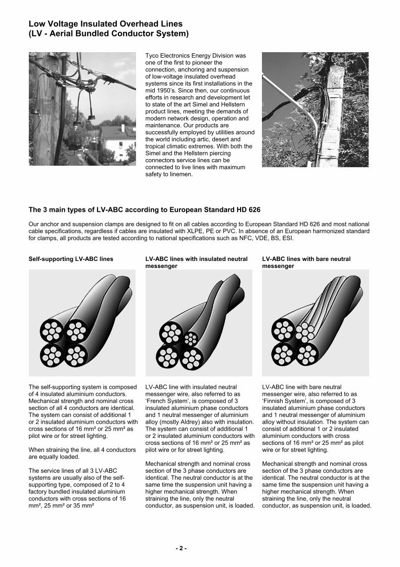
The 3 main types of LV-ABC according to European Standard HD 626 Our anchor and suspension clamps are designed to fit on all cables according to European Standard HD 626 and most national cable specifications, regardless if cables are insulated with XLPE, PE or PVC. In absence of an European harmonized standard for clamps, all products are tested according to national specifications such as NFC, VDE, BS, ESI. Self-supporting LV-ABC lines LV-ABC lines with insulated neutral
messenger LV-ABC lines with bare neutral messenger
The self-supporting system is composed of 4 insulated aluminium conductors. Mechanical strength and nominal cross section of all 4 conductors are identical. The system can consist of additional 1 or 2 insulated aluminium conductors with cross sections of 16 mm² or 25 mm² as pilot wire or for street lighting. When straining the line, all 4 conductors are equally loaded. The service lines of all 3 LV-ABC systems are usually also of the self-supporting type, composed of 2 to 4 factory bundled insulated aluminium conductors with cross sections of 16 mm², 25 mm² or 35 mm²
LV-ABC line with insulated neutral messenger wire, also referred to as ‘French System’, is composed of 3 insulated aluminium phase conductors and 1 neutral messenger of aluminium alloy (mostly Aldrey) also with insulation. The system can consist of additional 1 or 2 insulated aluminium conductors with cross sections of 16 mm² or 25 mm² as pilot wire or for street lighting. Mechanical strength and nominal cross section of the 3 phase conductors are identical. The neutral conductor is at the same time the suspension unit having a higher mechanical strength. When straining the line, only the neutral conductor, as suspension unit, is loaded.
LV-ABC line with bare neutral messenger wire, also referred to as ‘Finnish System’, is composed of 3 insulated aluminium phase conductors and 1 neutral messenger of aluminium alloy without insulation. The system can consist of additional 1 or 2 insulated aluminium conductors with cross sections of 16 mm² or 25 mm² as pilot wire or for street lighting. Mechanical strength and nominal cross section of the 3 phase conductors are identical. The neutral conductor is at the same time the suspension unit having a higher mechanical strength. When straining the line, only the neutral conductor, as suspension unit, is loaded.
- 3 -
Piercing Connector Systems
All our connectors are designed and tested to fit to all cables according to European Standard HD 626 and most national cable specifications, regardless if cables are insulated with XLPE, PE or PVC. In absence of an European harmonized standard for insulation piercing connectors, all products are tested according to national specifications such as NFC, VDE, BS, ESI. The range of Hellstern piercing connectors is tested according to DIN VDE-0220 and can be classified to withstand 4 kV in air. Our waterproof range of SIMEL connectors and lugs conforms to the French standards NF C 33 020 (bolted) and NF C 33 021 (crimped) as well as the British standard EATS 43-14. These standards include tests to verify reliable operation even in the harshest environments: • Designed for Installation from -20°C up to +50°C • Operation experience with temperatures ranging from -55°C up to +60°C • No limitation of mechanical loads for main and branch conductors • Shear head forces are adapted to the required contact forces for each application
(main, service, lightning) • Voltage withstand to 6 kV and no moisture ingress even after immersion in a 30
cm waterbath for 30 min • No change in contact resistance and temperature after overloads and loadcycling • Voltage withstand to 6 kV after heavy weathering exposure (UV-light, humidity
and temperature cycling) • Corrosion resistance of metal parts proven in salt fog chamber and wet SO2 gas
chamber
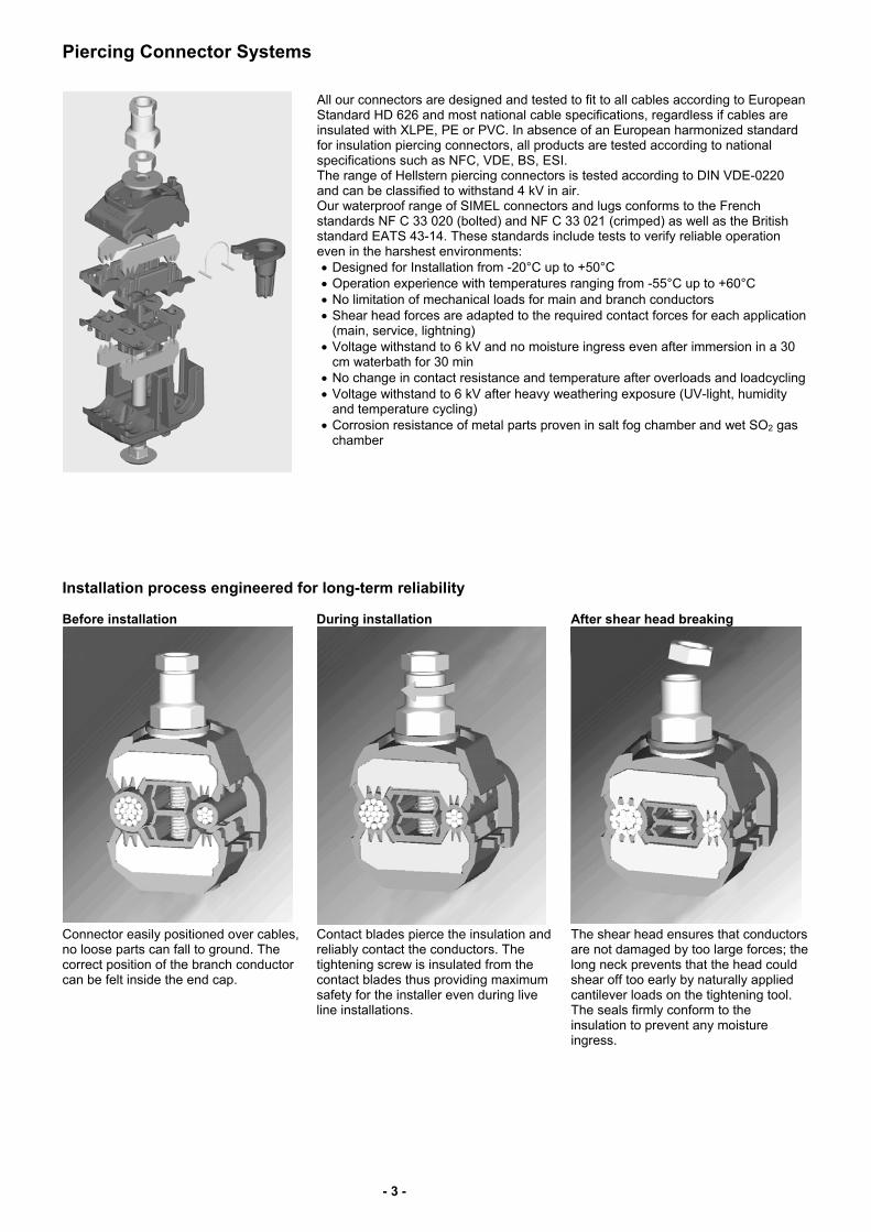
Installation process engineered for long-term reliability Before installation During installation After shear head breaking
Connector easily positioned over cables, no loose parts can fall to ground. The correct position of the branch conductor can be felt inside the end cap.
Contact blades pierce the insulation and reliably contact the conductors. The tightening screw is insulated from the contact blades thus providing maximum safety for the installer even during live line installations.
The shear head ensures that conductors are not damaged by too large forces; the long neck prevents that the head could shear off too early by naturally applied cantilever loads on the tightening tool. The seals firmly conform to the insulation to prevent any moisture ingress.
- 4 -
Insulation piercing connectors – test voltage 4 kV in air
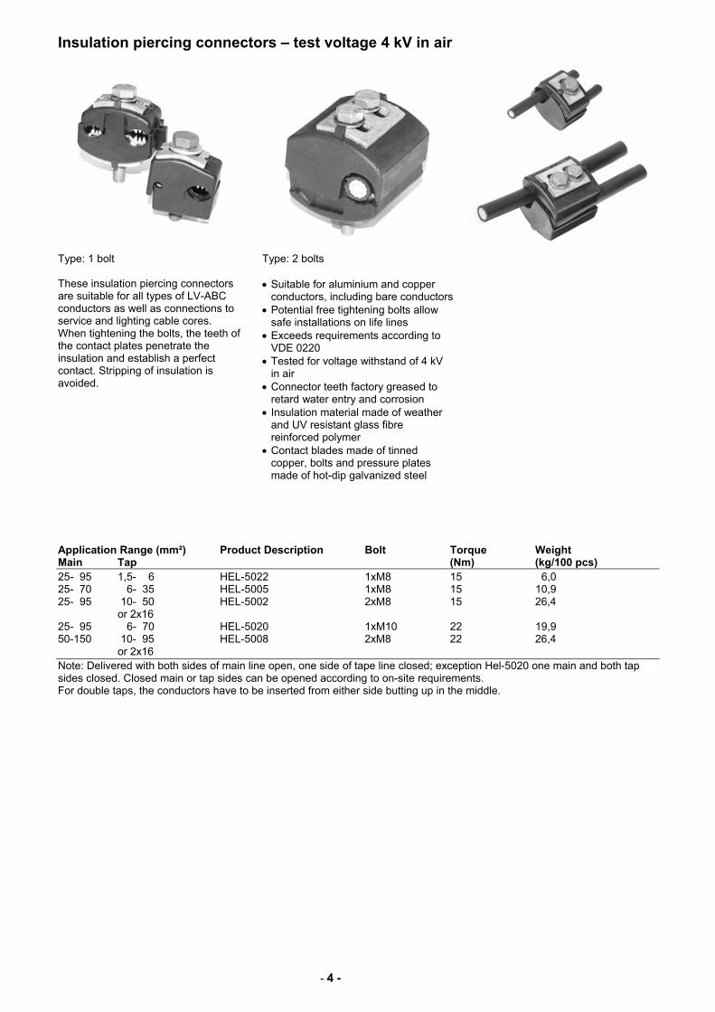
Type: 1 bolt
Type: 2 bolts
These insulation piercing connectors are suitable for all types of LV-ABC conductors as well as connections to service and lighting cable cores. When tightening the bolts, the teeth of the contact plates penetrate the insulation and establish a perfect contact. Stripping of insulation is avoided.
• Suitable for aluminium and copper conductors, including bare conductors
• Potential free tightening bolts allow safe installations on life lines
• Exceeds requirements according to VDE 0220
• Tested for voltage withstand of 4 kV in air
• Connector teeth factory greased to retard water entry and corrosion
• Insulation material made of weather and UV resistant glass fibre reinforced polymer
• Contact blades made of tinned copper, bolts and pressure plates made of hot-dip galvanized steel
Application Range (mm²) Product Description Bolt Torque Weight Main Tap (Nm) (kg/100 pcs) 25- 95 1,5- 6 HEL-5022 1xM8 15 6,0 25- 70 6- 35 HEL-5005 1xM8 15 10,9 25- 95 10- 50 HEL-5002 2xM8 15 26,4 or 2x16 25- 95 6- 70 HEL-5020 1xM10 22 19,9 50-150 10- 95 HEL-5008 2xM8 22 26,4 or 2x16 Note: Delivered with both sides of main line open, one side of tape line closed; exception Hel-5020 one main and both tap sides closed. Closed main or tap sides can be opened according to on-site requirements. For double taps, the conductors have to be inserted from either side butting up in the middle.
- 5 -
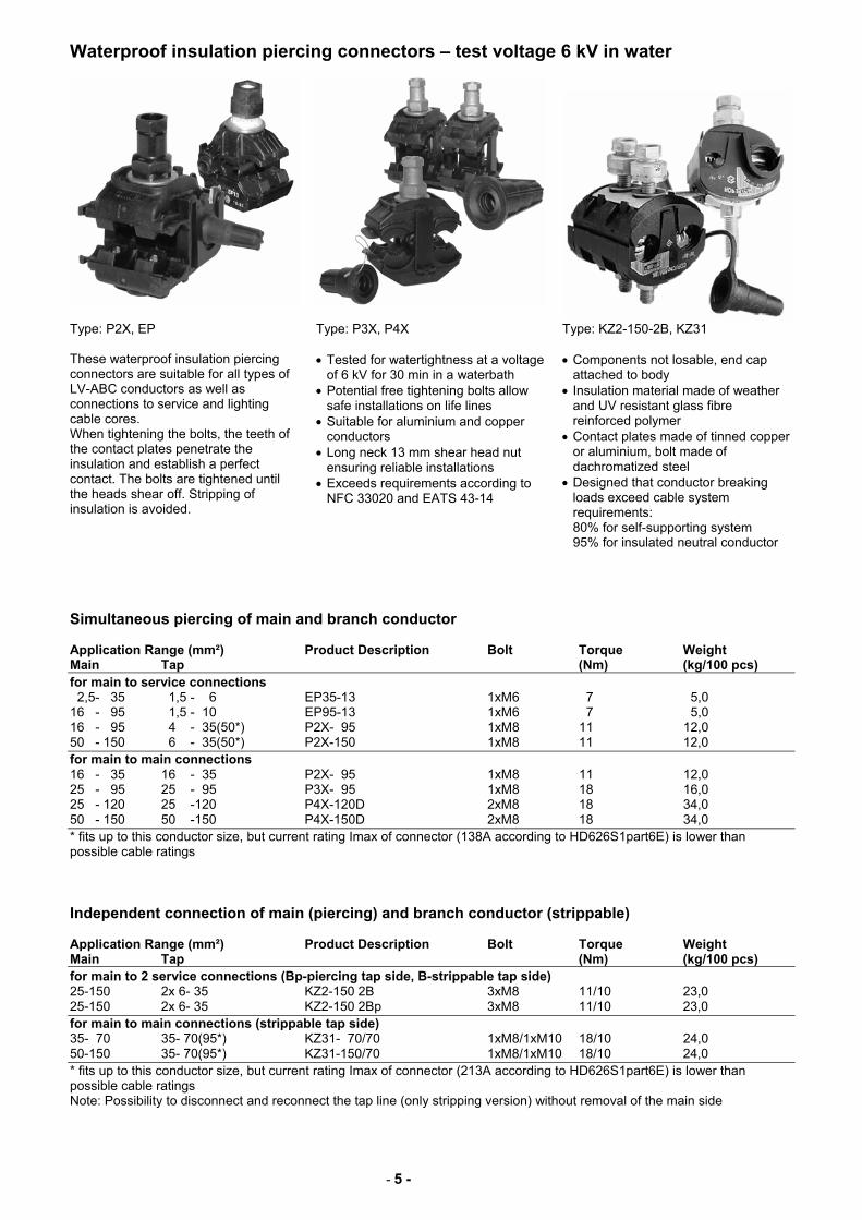
Waterproof insulation piercing connectors – test voltage 6 kV in water
Type: P2X, EP
Type: P3X, P4X Type: KZ2-150-2B, KZ31
These waterproof insulation piercing connectors are suitable for all types of LV-ABC conductors as well as connections to service and lighting cable cores. When tightening the bolts, the teeth of the contact plates penetrate the insulation and establish a perfect contact. The bolts are tightened until the heads shear off. Stripping of insulation is avoided.
• Tested for watertightness at a voltage of 6 kV for 30 min in a waterbath
• Potential free tightening bolts allow safe installations on life lines
• Suitable for aluminium and copper conductors
• Long neck 13 mm shear head nut ensuring reliable installations
• Exceeds requirements according to NFC 33020 and EATS 43-14
• Components not losable, end cap attached to body
• Insulation material made of weather and UV resistant glass fibre reinforced polymer
• Contact plates made of tinned copper or aluminium, bolt made of dachromatized steel
• Designed that conductor breaking loads exceed cable system requirements: 80% for self-supporting system 95% for insulated neutral conductor
Simultaneous piercing of main and branch conductor Application Range (mm²) Product Description Bolt Torque Weight Main Tap (Nm) (kg/100 pcs) for main to service connections 2,5- 35 1,5 - 6 EP35-13 1xM6 7 5,0 16 - 95 1,5 - 10 EP95-13 1xM6 7 5,0 16 - 95 4 - 35(50*) P2X- 95 1xM8 11 12,0 50 - 150 6 - 35(50*) P2X-150 1xM8 11 12,0 for main to main connections 16 - 35 16 - 35 P2X- 95 1xM8 11 12,0 25 - 95 25 - 95 P3X- 95 1xM8 18 16,0 25 - 120 25 -120 P4X-120D 2xM8 18 34,0 50 - 150 50 -150 P4X-150D 2xM8 18 34,0 * fits up to this conductor size, but current rating Imax of connector (138A according to HD626S1part6E) is lower than possible cable ratings Independent connection of main (piercing) and branch conductor (strippable) Application Range (mm²) Product Description Bolt Torque Weight Main Tap (Nm) (kg/100 pcs) for main to 2 service connections (Bp-piercing tap side, B-strippable tap side) 25-150 2x 6- 35 KZ2-150 2B 3xM8 11/10 23,0 25-150 2x 6- 35 KZ2-150 2Bp 3xM8 11/10 23,0 for main to main connections (strippable tap side) 35- 70 35- 70(95*) KZ31- 70/70 1xM8/1xM10 18/10 24,0 50-150 35- 70(95*) KZ31-150/70 1xM8/1xM10 18/10 24,0 * fits up to this conductor size, but current rating Imax of connector (213A according to HD626S1part6E) is lower than possible cable ratings Note: Possibility to disconnect and reconnect the tap line (only stripping version) without removal of the main side
- 6 -
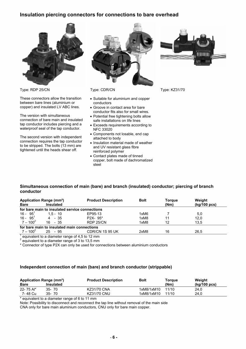
Insulation piercing connectors for connections to bare overhead
Type: RDP 25/CN
Type: CDR/CN Type: KZ31/70
These connectors allow the transition between bare lines (aluminium or copper) and insulated LV ABC lines. The version with simultaneous connection of bare main and insulated tap conductor includes piercing and a waterproof seal of the tap conductor. The second version with independent connection requires the tap conductor to be stripped. The bolts (13 mm) are tightened until the heads shear off.
• Suitable for aluminium and copper conductors
• Groove in contact area for bare conductor fits also for small wires.
• Potential free tightening bolts allow safe installations on life lines
• Exceeds requirements according to NFC 33020
• Components not losable, end cap attached to body
• Insulation material made of weather and UV resistant glass fibre reinforced polymer
• Contact plates made of tinned copper, bolt made of dachromatized steel
Simultaneous connection of main (bare) and branch (insulated) conductor; piercing of branch conductor Application Range (mm²) Product Description Bolt Torque Weight Bare Insulated (Nm) (kg/100 pcs) for bare main to insulated service connections 16 - 951 1,5 - 10 EP95-13 1xM6 7 5,0 16 - 951 4 - 35 P2X- 95* 1xM8 11 12,0 7 – 1002 16 - 35 RDP 25/CN 1xM8 12 13,5 for bare main to insulated main connections 7 – 1002 25 - 95 CDR/CN 1S 95 UK 2xM8 16 26,5 1 equivalent to a diameter range of 4,5 to 12 mm 2 equivalent to a diameter range of 3 to 13,5 mm * Connector of type P2X can only be used for connections between aluminium conductors Independent connection of main (bare) and branch conductor (strippable) Application Range (mm²) Product Description Bolt Torque Weight Bare Insulated (Nm) (kg/100 pcs) 22- 75 Al* 35- 70 KZ31/70 CNA 1xM8/1xM10 11/10 24,0 7- 48 Cu 35- 70 KZ31/70 CNU 1xM8/1xM10 11/10 24,0 * equivalent to a diameter range of 6 to 11 mm Note: Possibility to disconnect and reconnect the tap line without removal of the main side CNA only for bare main aluminium conductors, CNU only for bare main copper.
- 7 -
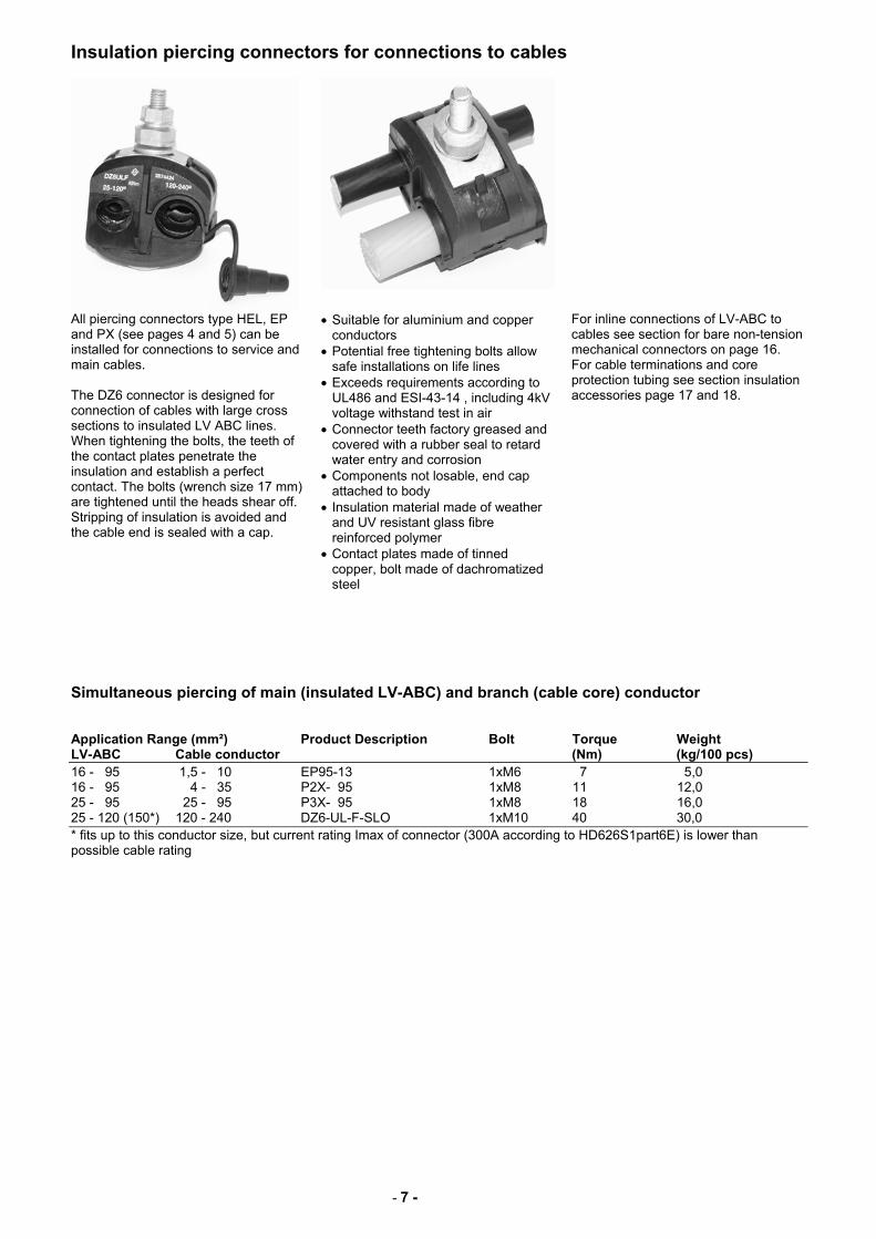
Insulation piercing connectors for connections to cables
All piercing connectors type HEL, EP and PX (see pages 4 and 5) can be installed for connections to service and main cables. The DZ6 connector is designed for connection of cables with large cross sections to insulated LV ABC lines. When tightening the bolts, the teeth of the contact plates penetrate the insulation and establish a perfect contact. The bolts (wrench size 17 mm) are tightened until the heads shear off. Stripping of insulation is avoided and the cable end is sealed with a cap.
• Suitable for aluminium and copper conductors
• Potential free tightening bolts allow safe installations on life lines
• Exceeds requirements according to UL486 and ESI-43-14 , including 4kV voltage withstand test in air
• Connector teeth factory greased and covered with a rubber seal to retard water entry and corrosion
• Components not losable, end cap attached to body
• Insulation material made of weather and UV resistant glass fibre reinforced polymer
• Contact plates made of tinned copper, bolt made of dachromatized steel
For inline connections of LV-ABC to cables see section for bare non-tension mechanical connectors on page 16. For cable terminations and core protection tubing see section insulation accessories page 17 and 18.
Simultaneous piercing of main (insulated LV-ABC) and branch (cable core) conductor Application Range (mm²) Product Description Bolt Torque Weight LV-ABC Cable conductor (Nm) (kg/100 pcs) 16 - 95 1,5 - 10 EP95-13 1xM6 7 5,0 16 - 95 4 - 35 P2X- 95 1xM8 11 12,0 25 - 95 25 - 95 P3X- 95 1xM8 18 16,0 25 - 120 (150*) 120 - 240 DZ6-UL-F-SLO 1xM10 40 30,0 * fits up to this conductor size, but current rating Imax of connector (300A according to HD626S1part6E) is lower than possible cable rating
- 8 -
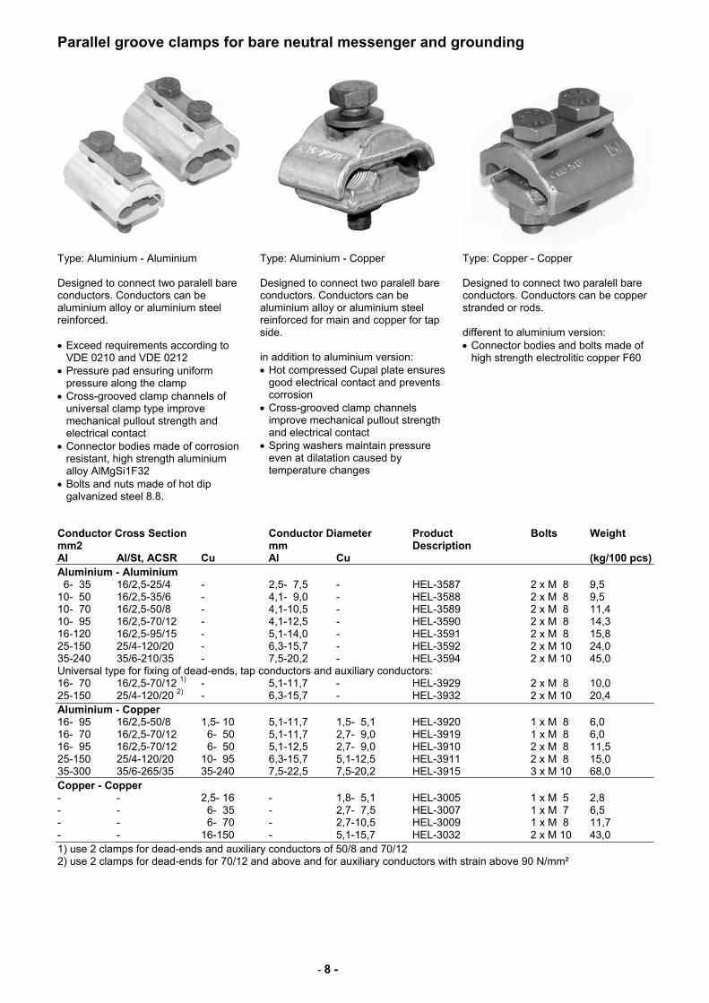
Parallel groove clamps for bare neutral messenger and grounding
Type: Aluminium - Aluminium
Type: Aluminium - Copper Type: Copper - Copper
Designed to connect two paralell bare conductors. Conductors can be aluminium alloy or aluminium steel reinforced. • Exceed requirements according to
VDE 0210 and VDE 0212 • Pressure pad ensuring uniform
pressure along the clamp • Cross-grooved clamp channels of
universal clamp type improve mechanical pullout strength and electrical contact
• Connector bodies made of corrosion resistant, high strength aluminium alloy AlMgSi1F32
• Bolts and nuts made of hot dip galvanized steel 8.8.
Designed to connect two paralell bare conductors. Conductors can be aluminium alloy or aluminium steel reinforced for main and copper for tap side. in addition to aluminium version: • Hot compressed Cupal plate ensures
good electrical contact and prevents corrosion
• Cross-grooved clamp channels improve mechanical pullout strength and electrical contact
• Spring washers maintain pressure even at dilatation caused by temperature changes
Designed to connect two paralell bare conductors. Conductors can be copper stranded or rods. different to aluminium version: • Connector bodies and bolts made of
high strength electrolitic copper F60
Conductor Cross Section Conductor Diameter Product Bolts Weight mm2 mm Description Al Al/St, ACSR Cu Al Cu (kg/100 pcs) Aluminium - Aluminium 6- 35 16/2,5-25/4 - 2,5- 7,5 - HEL-3587 2 x M 8 9,5 10- 50 16/2,5-35/6 - 4,1- 9,0 - HEL-3588 2 x M 8 9,5 10- 70 16/2,5-50/8 - 4,1-10,5 - HEL-3589 2 x M 8 11,4 10- 95 16/2,5-70/12 - 4,1-12,5 - HEL-3590 2 x M 8 14,3 16-120 16/2,5-95/15 - 5,1-14,0 - HEL-3591 2 x M 8 15,8 25-150 25/4-120/20 - 6,3-15,7 - HEL-3592 2 x M 10 24,0 35-240 35/6-210/35 - 7,5-20,2 - HEL-3594 2 x M 10 45,0 Universal type for fixing of dead-ends, tap conductors and auxiliary conductors: 16- 70 16/2,5-70/12 1) - 5,1-11,7 - HEL-3929 2 x M 8 10,0 25-150 25/4-120/20 2) - 6,3-15,7 - HEL-3932 2 x M 10 20,4 Aluminium - Copper 16- 95 16/2,5-50/8 1,5- 10 5,1-11,7 1,5- 5,1 HEL-3920 1 x M 8 6,0 16- 70 16/2,5-70/12 6- 50 5,1-11,7 2,7- 9,0 HEL-3919 1 x M 8 6,0 16- 95 16/2,5-70/12 6- 50 5,1-12,5 2,7- 9,0 HEL-3910 2 x M 8 11,5 25-150 25/4-120/20 10- 95 6,3-15,7 5,1-12,5 HEL-3911 2 x M 8 15,0 35-300 35/6-265/35 35-240 7,5-22,5 7,5-20,2 HEL-3915 3 x M 10 68,0 Copper - Copper - - 2,5- 16 - 1,8- 5,1 HEL-3005 1 x M 5 2,8 - - 6- 35 - 2,7- 7,5 HEL-3007 1 x M 7 6,5 - - 6- 70 - 2,7-10,5 HEL-3009 1 x M 8 11,7 - - 16-150 - 5,1-15,7 HEL-3032 2 x M 10 43,0 1) use 2 clamps for dead-ends and auxiliary conductors of 50/8 and 70/12 2) use 2 clamps for dead-ends for 70/12 and above and for auxiliary conductors with strain above 90 N/mm²
- 9 -
Compression branch connectors and sealing kits
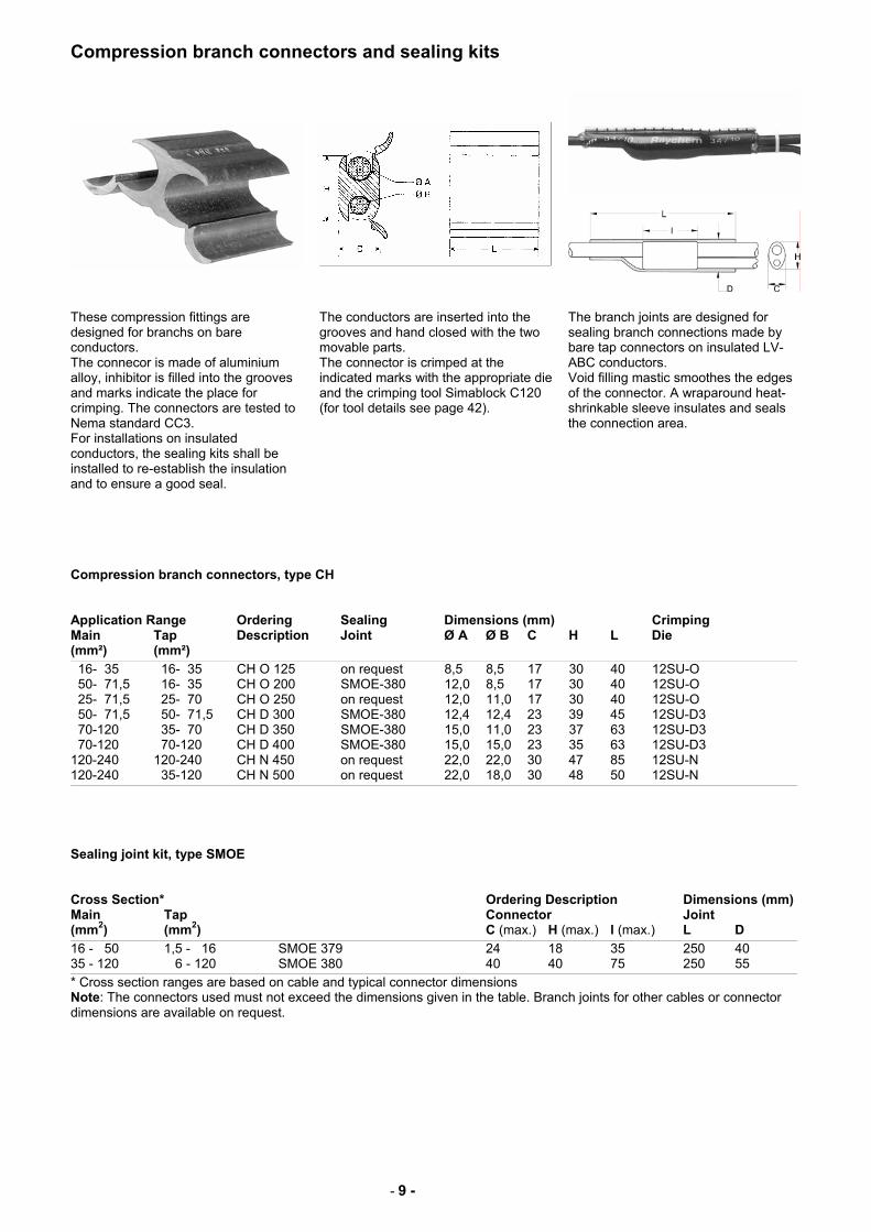
These compression fittings are designed for branchs on bare conductors. The connecor is made of aluminium alloy, inhibitor is filled into the grooves and marks indicate the place for crimping. The connectors are tested to Nema standard CC3. For installations on insulated conductors, the sealing kits shall be installed to re-establish the insulation and to ensure a good seal.
The conductors are inserted into the grooves and hand closed with the two movable parts. The connector is crimped at the indicated marks with the appropriate die and the crimping tool Simablock C120 (for tool details see page 42).
The branch joints are designed for sealing branch connections made by bare tap connectors on insulated LV-ABC conductors. Void filling mastic smoothes the edges of the connector. A wraparound heat-shrinkable sleeve insulates and seals the connection area.
Compression branch connectors, type CH Application Range Ordering Sealing Dimensions (mm) Crimping Main Tap Description Joint Ø A Ø B C H L Die (mm²) (mm²)
16- 35 16- 35 CH O 125 on request 8,5 8,5 17 30 40 12SU-O 50- 71,5 16- 35 CH O 200 SMOE-380 12,0 8,5 17 30 40 12SU-O 25- 71,5 25- 70 CH O 250 on request 12,0 11,0 17 30 40 12SU-O 50- 71,5 50- 71,5 CH D 300 SMOE-380 12,4 12,4 23 39 45 12SU-D3 70-120 35- 70 CH D 350 SMOE-380 15,0 11,0 23 37 63 12SU-D3 70-120 70-120 CH D 400 SMOE-380 15,0 15,0 23 35 63 12SU-D3 120-240 120-240 CH N 450 on request 22,0 22,0 30 47 85 12SU-N 120-240 35-120 CH N 500 on request 22,0 18,0 30 48 50 12SU-N
Sealing joint kit, type SMOE Cross Section* Ordering Description Dimensions (mm) Main Tap Connector Joint (mm2) (mm2) C (max.) H (max.) l (max.) L D
16 - 50 1,5 - 16 SMOE 379 24 18 35 250 40 35 - 120 6 - 120 SMOE 380 40 40 75 250 55
* Cross section ranges are based on cable and typical connector dimensions Note: The connectors used must not exceed the dimensions given in the table. Branch joints for other cables or connector dimensions are available on request.
- 10 -
Waterproof pre-insulated mechanical connectors for service cables
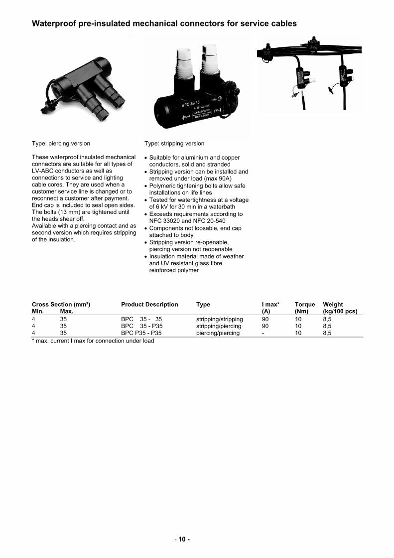
Type: piercing version
Type: stripping version
These waterproof insulated mechanical connectors are suitable for all types of LV-ABC conductors as well as connections to service and lighting cable cores. They are used when a customer service line is changed or to reconnect a customer after payment. End cap is included to seal open sides. The bolts (13 mm) are tightened until the heads shear off. Available with a piercing contact and as second version which requires stripping of the insulation.
• Suitable for aluminium and copper conductors, solid and stranded
• Stripping version can be installed and removed under load (max 90A)
• Polymeric tightening bolts allow safe installations on life lines
• Tested for watertightness at a voltage of 6 kV for 30 min in a waterbath
• Exceeds requirements according to NFC 33020 and NFC 20-540
• Components not loosable, end cap attached to body
• Stripping version re-openable, piercing version not reopenable
• Insulation material made of weather and UV resistant glass fibre reinforced polymer
Cross Section (mm²) Product Description Type I max* Torque Weight Min. Max. (A) (Nm) (kg/100 pcs) 4 35 BPC 35 - 35 stripping/stripping 90 10 8,5 4 35 BPC 35 - P35 stripping/piercing 90 10 8,5 4 35 BPC P35 - P35 piercing/piercing - 10 8,5 * max. current I max for connection under load
- 11 -
Waterproof pre-insulated hexagonal compression connectors for service cables
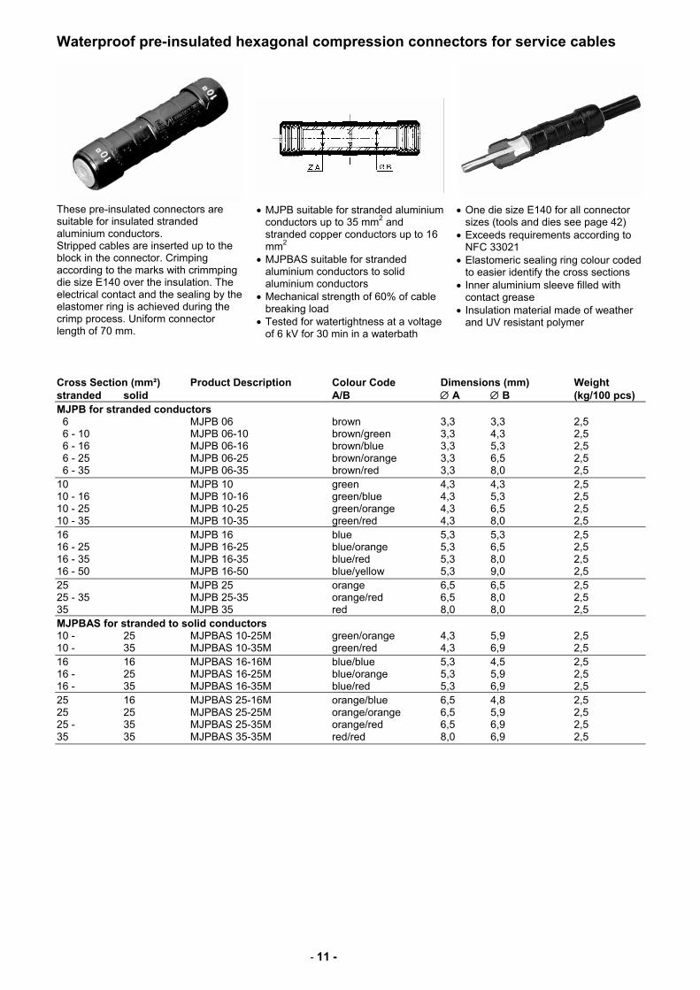
These pre-insulated connectors are suitable for insulated stranded aluminium conductors. Stripped cables are inserted up to the block in the connector. Crimping according to the marks with crimmping die size E140 over the insulation. The electrical contact and the sealing by the elastomer ring is achieved during the crimp process. Uniform connector length of 70 mm.
• MJPB suitable for stranded aluminium conductors up to 35 mm2 and stranded copper conductors up to 16 mm2
• MJPBAS suitable for stranded aluminium conductors to solid aluminium conductors
• Mechanical strength of 60% of cable breaking load
• Tested for watertightness at a voltage of 6 kV for 30 min in a waterbath
• One die size E140 for all connector sizes (tools and dies see page 42)
• Exceeds requirements according to NFC 33021
• Elastomeric sealing ring colour coded to easier identify the cross sections
• Inner aluminium sleeve filled with contact grease
• Insulation material made of weather and UV resistant polymer
Cross Section (mm²) Product Description Colour Code Dimensions (mm) Weight stranded solid A/B ∅ A ∅ B (kg/100 pcs) MJPB for stranded conductors 6 MJPB 06 brown 3,3 3,3 2,5 6 - 10 MJPB 06-10 brown/green 3,3 4,3 2,5 6 - 16 MJPB 06-16 brown/blue 3,3 5,3 2,5 6 - 25 MJPB 06-25 brown/orange 3,3 6,5 2,5 6 - 35 MJPB 06-35 brown/red 3,3 8,0 2,5 10 MJPB 10 green 4,3 4,3 2,5 10 - 16 MJPB 10-16 green/blue 4,3 5,3 2,5 10 - 25 MJPB 10-25 green/orange 4,3 6,5 2,5 10 - 35 MJPB 10-35 green/red 4,3 8,0 2,5 16 MJPB 16 blue 5,3 5,3 2,5 16 - 25 MJPB 16-25 blue/orange 5,3 6,5 2,5 16 - 35 MJPB 16-35 blue/red 5,3 8,0 2,5 16 - 50 MJPB 16-50 blue/yellow 5,3 9,0 2,5 25 MJPB 25 orange 6,5 6,5 2,5 25 - 35 MJPB 25-35 orange/red 6,5 8,0 2,5 35 MJPB 35 red 8,0 8,0 2,5 MJPBAS for stranded to solid conductors 10 - 25 MJPBAS 10-25M green/orange 4,3 5,9 2,5 10 - 35 MJPBAS 10-35M green/red 4,3 6,9 2,5 16 16 MJPBAS 16-16M blue/blue 5,3 4,5 2,5 16 - 25 MJPBAS 16-25M blue/orange 5,3 5,9 2,5 16 - 35 MJPBAS 16-35M blue/red 5,3 6,9 2,5 25 16 MJPBAS 25-16M orange/blue 6,5 4,8 2,5 25 25 MJPBAS 25-25M orange/orange 6,5 5,9 2,5 25 - 35 MJPBAS 25-35M orange/red 6,5 6,9 2,5 35 35 MJPBAS 35-35M red/red 8,0 6,9 2,5
- 12 -
Waterproof pre-insulated hexagonal compression connectors
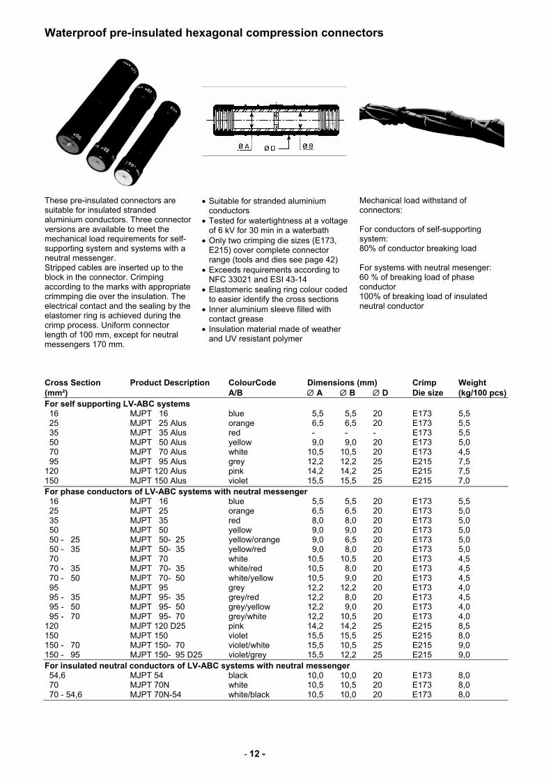
These pre-insulated connectors are suitable for insulated stranded aluminium conductors. Three connector versions are available to meet the mechanical load requirements for self-supporting system and systems with a neutral messenger. Stripped cables are inserted up to the block in the connector. Crimping according to the marks with appropriate crimmping die over the insulation. The electrical contact and the sealing by the elastomer ring is achieved during the crimp process. Uniform connector length of 100 mm, except for neutral messengers 170 mm.
• Suitable for stranded aluminium conductors
• Tested for watertightness at a voltage of 6 kV for 30 min in a waterbath
• Only two crimping die sizes (E173, E215) cover complete connector range (tools and dies see page 42)
• Exceeds requirements according to NFC 33021 and ESI 43-14
• Elastomeric sealing ring colour coded to easier identify the cross sections
• Inner aluminium sleeve filled with contact grease
• Insulation material made of weather and UV resistant polymer
Mechanical load withstand of connectors: For conductors of self-supporting system: 80% of conductor breaking load For systems with neutral mesenger: 60 % of breaking load of phase conductor 100% of breaking load of insulated neutral conductor
Cross Section Product Description ColourCode Dimensions (mm) Crimp Weight (mm²) A/B ∅ A ∅ B ∅ D Die size (kg/100 pcs) For self supporting LV-ABC systems 16 MJPT 16 blue 5,5 5,5 20 E173 5,5 25 MJPT 25 Alus orange 6,5 6,5 20 E173 5,5 35 MJPT 35 Alus red - - - E173 5,5 50 MJPT 50 Alus yellow 9,0 9,0 20 E173 5,0 70 MJPT 70 Alus white 10,5 10,5 20 E173 4,5 95 MJPT 95 Alus grey 12,2 12,2 25 E215 7,5 120 MJPT 120 Alus pink 14,2 14,2 25 E215 7,5 150 MJPT 150 Alus violet 15,5 15,5 25 E215 7,0 For phase conductors of LV-ABC systems with neutral messenger 16 MJPT 16 blue 5,5 5,5 20 E173 5,5 25 MJPT 25 orange 6,5 6,5 20 E173 5,0 35 MJPT 35 red 8,0 8,0 20 E173 5,0 50 MJPT 50 yellow 9,0 9,0 20 E173 5,0 50 - 25 MJPT 50- 25 yellow/orange 9,0 6,5 20 E173 5,0 50 - 35 MJPT 50- 35 yellow/red 9,0 8,0 20 E173 5,0 70 MJPT 70 white 10,5 10,5 20 E173 4,5 70 - 35 MJPT 70- 35 white/red 10,5 8,0 20 E173 4,5 70 - 50 MJPT 70- 50 white/yellow 10,5 9,0 20 E173 4,5 95 MJPT 95 grey 12,2 12,2 20 E173 4,0 95 - 35 MJPT 95- 35 grey/red 12,2 8,0 20 E173 4,5 95 - 50 MJPT 95- 50 grey/yellow 12,2 9,0 20 E173 4,0 95 - 70 MJPT 95- 70 grey/white 12,2 10,5 20 E173 4,0 120 MJPT 120 D25 pink 14,2 14,2 25 E215 8,5 150 MJPT 150 violet 15,5 15,5 25 E215 8,0 150 - 70 MJPT 150- 70 violet/white 15,5 10,5 25 E215 9,0 150 - 95 MJPT 150- 95 D25 violet/grey 15,5 12,2 25 E215 9,0 For insulated neutral conductors of LV-ABC systems with neutral messenger 54,6 MJPT 54 black 10,0 10,0 20 E173 8,0 70 MJPT 70N white 10,5 10,5 20 E173 8,0 70 - 54,6 MJPT 70N-54 white/black 10,5 10,0 20 E173 8,0
- 13 -
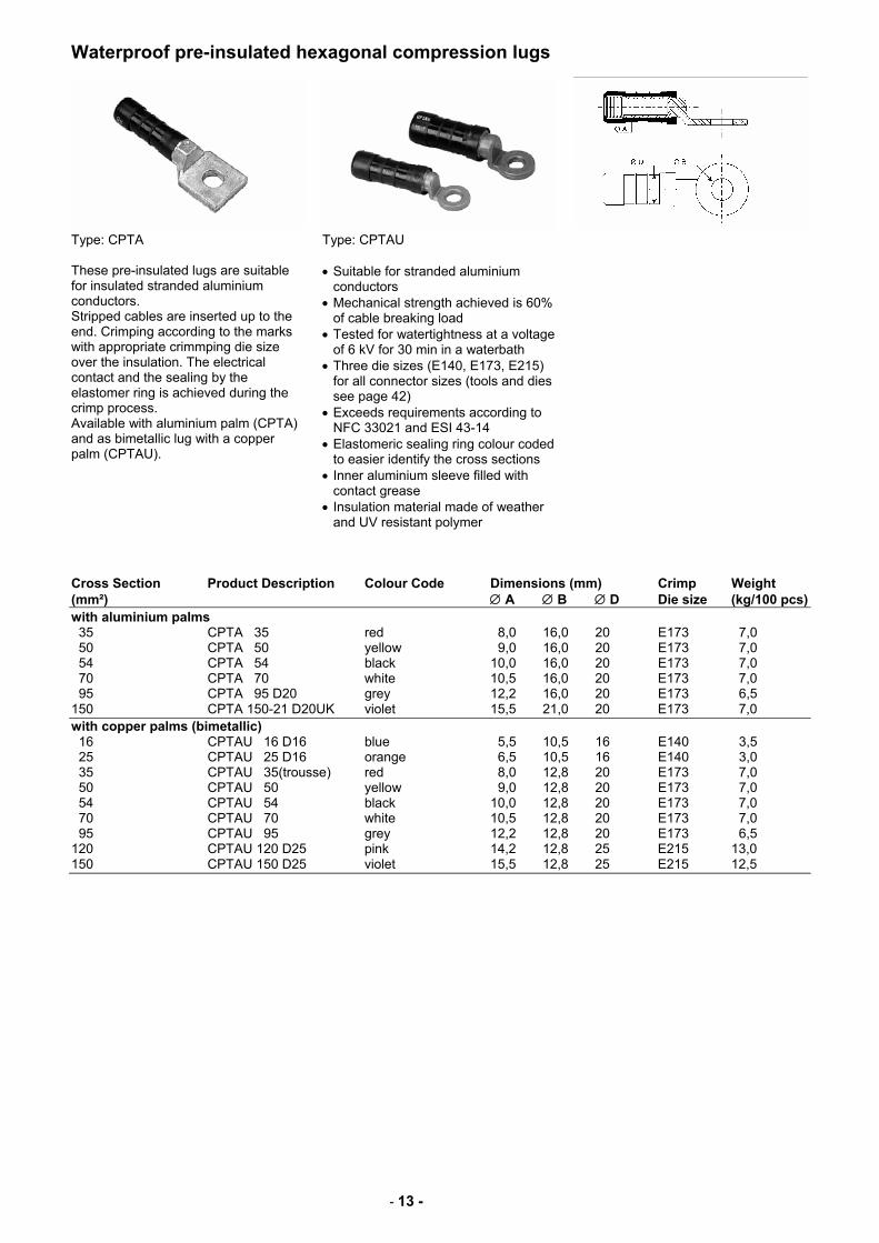
Waterproof pre-insulated hexagonal compression lugs
Type: CPTA
Type: CPTAU
These pre-insulated lugs are suitable for insulated stranded aluminium conductors. Stripped cables are inserted up to the end. Crimping according to the marks with appropriate crimmping die size over the insulation. The electrical contact and the sealing by the elastomer ring is achieved during the crimp process. Available with aluminium palm (CPTA) and as bimetallic lug with a copper palm (CPTAU).
• Suitable for stranded aluminium conductors
• Mechanical strength achieved is 60% of cable breaking load
• Tested for watertightness at a voltage of 6 kV for 30 min in a waterbath
• Three die sizes (E140, E173, E215) for all connector sizes (tools and dies see page 42)
• Exceeds requirements according to NFC 33021 and ESI 43-14
• Elastomeric sealing ring colour coded to easier identify the cross sections
• Inner aluminium sleeve filled with contact grease
• Insulation material made of weather and UV resistant polymer
Cross Section Product Description Colour Code Dimensions (mm) Crimp Weight (mm²) ∅ A ∅ B ∅ D Die size (kg/100 pcs) with aluminium palms 35 CPTA 35 red 8,0 16,0 20 E173 7,0 50 CPTA 50 yellow 9,0 16,0 20 E173 7,0 54 CPTA 54 black 10,0 16,0 20 E173 7,0 70 CPTA 70 white 10,5 16,0 20 E173 7,0 95 CPTA 95 D20 grey 12,2 16,0 20 E173 6,5 150 CPTA 150-21 D20UK violet 15,5 21,0 20 E173 7,0 with copper palms (bimetallic) 16 CPTAU 16 D16 blue 5,5 10,5 16 E140 3,5 25 CPTAU 25 D16 orange 6,5 10,5 16 E140 3,0 35 CPTAU 35(trousse) red 8,0 12,8 20 E173 7,0 50 CPTAU 50 yellow 9,0 12,8 20 E173 7,0 54 CPTAU 54 black 10,0 12,8 20 E173 7,0 70 CPTAU 70 white 10,5 12,8 20 E173 7,0 95 CPTAU 95 grey 12,2 12,8 20 E173 6,5 120 CPTAU 120 D25 pink 14,2 12,8 25 E215 13,0 150 CPTAU 150 D25 violet 15,5 12,8 25 E215 12,5
- 14 -
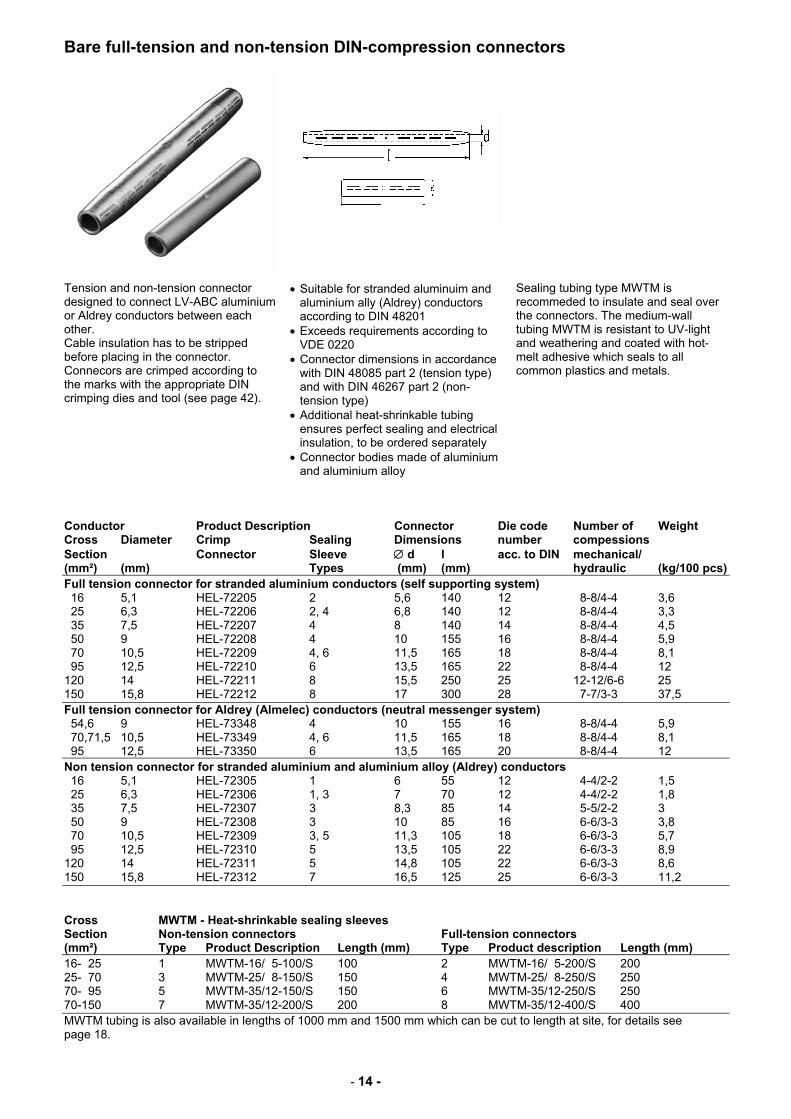
Bare full-tension and non-tension DIN-compression connectors
Tension and non-tension connector designed to connect LV-ABC aluminium or Aldrey conductors between each other. Cable insulation has to be stripped before placing in the connector. Connecors are crimped according to the marks with the appropriate DIN crimping dies and tool (see page 42).
• Suitable for stranded aluminuim and aluminium ally (Aldrey) conductors according to DIN 48201
• Exceeds requirements according to VDE 0220
• Connector dimensions in accordance with DIN 48085 part 2 (tension type) and with DIN 46267 part 2 (non-tension type)
• Additional heat-shrinkable tubing ensures perfect sealing and electrical insulation, to be ordered separately
• Connector bodies made of aluminium and aluminium alloy
Sealing tubing type MWTM is recommeded to insulate and seal over the connectors. The medium-wall tubing MWTM is resistant to UV-light and weathering and coated with hot-melt adhesive which seals to all common plastics and metals.
Conductor Product Description Connector Die code Number of Weight Cross Diameter Crimp Sealing Dimensions number compessions Section Connector Sleeve ∅ d l acc. to DIN mechanical/ (mm²) (mm) Types (mm) (mm) hydraulic (kg/100 pcs) Full tension connector for stranded aluminium conductors (self supporting system) 16 5,1 HEL-72205 2 5,6 140 12 8-8/4-4 3,6 25 6,3 HEL-72206 2, 4 6,8 140 12 8-8/4-4 3,3 35 7,5 HEL-72207 4 8 140 14 8-8/4-4 4,5 50 9 HEL-72208 4 10 155 16 8-8/4-4 5,9 70 10,5 HEL-72209 4, 6 11,5 165 18 8-8/4-4 8,1 95 12,5 HEL-72210 6 13,5 165 22 8-8/4-4 12 120 14 HEL-72211 8 15,5 250 25 12-12/6-6 25 150 15,8 HEL-72212 8 17 300 28 7-7/3-3 37,5 Full tension connector for Aldrey (Almelec) conductors (neutral messenger system) 54,6 9 HEL-73348 4 10 155 16 8-8/4-4 5,9 70,71,5 10,5 HEL-73349 4, 6 11,5 165 18 8-8/4-4 8,1 95 12,5 HEL-73350 6 13,5 165 20 8-8/4-4 12 Non tension connector for stranded aluminium and aluminium alloy (Aldrey) conductors 16 5,1 HEL-72305 1 6 55 12 4-4/2-2 1,5 25 6,3 HEL-72306 1, 3 7 70 12 4-4/2-2 1,8 35 7,5 HEL-72307 3 8,3 85 14 5-5/2-2 3 50 9 HEL-72308 3 10 85 16 6-6/3-3 3,8 70 10,5 HEL-72309 3, 5 11,3 105 18 6-6/3-3 5,7 95 12,5 HEL-72310 5 13,5 105 22 6-6/3-3 8,9 120 14 HEL-72311 5 14,8 105 22 6-6/3-3 8,6 150 15,8 HEL-72312 7 16,5 125 25 6-6/3-3 11,2 Cross MWTM - Heat-shrinkable sealing sleeves Section Non-tension connectors Full-tension connectors (mm²) Type Product Description Length (mm) Type Product description Length (mm) 16- 25 1 MWTM-16/ 5-100/S 100 2 MWTM-16/ 5-200/S 200 25- 70 3 MWTM-25/ 8-150/S 150 4 MWTM-25/ 8-250/S 250 70- 95 5 MWTM-35/12-150/S 150 6 MWTM-35/12-250/S 250 70-150 7 MWTM-35/12-200/S 200 8 MWTM-35/12-400/S 400 MWTM tubing is also available in lengths of 1000 mm and 1500 mm which can be cut to length at site, for details see page 18.
- 15 -
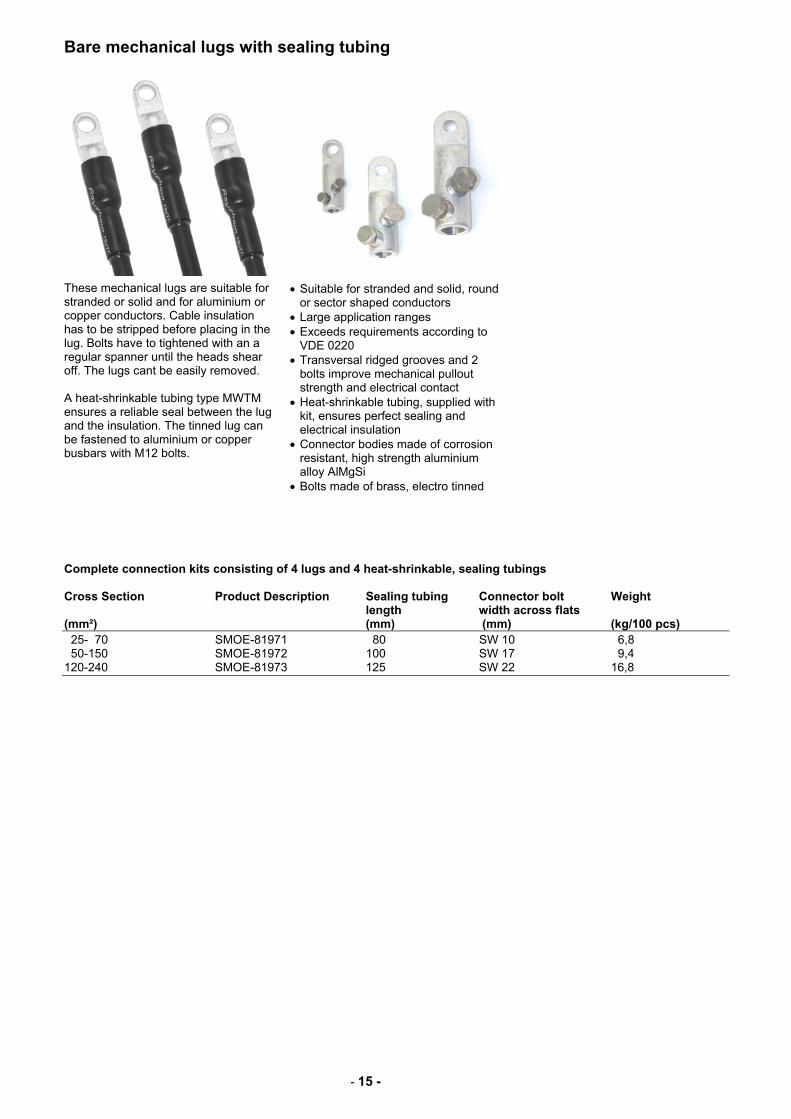
Bare mechanical lugs with sealing tubing
These mechanical lugs are suitable for stranded or solid and for aluminium or copper conductors. Cable insulation has to be stripped before placing in the lug. Bolts have to tightened with an a regular spanner until the heads shear off. The lugs cant be easily removed. A heat-shrinkable tubing type MWTM ensures a reliable seal between the lug and the insulation. The tinned lug can be fastened to aluminium or copper busbars with M12 bolts.
• Suitable for stranded and solid, round or sector shaped conductors
• Large application ranges • Exceeds requirements according to
VDE 0220 • Transversal ridged grooves and 2
bolts improve mechanical pullout strength and electrical contact
• Heat-shrinkable tubing, supplied with kit, ensures perfect sealing and electrical insulation
• Connector bodies made of corrosion resistant, high strength aluminium alloy AlMgSi
• Bolts made of brass, electro tinned
Complete connection kits consisting of 4 lugs and 4 heat-shrinkable, sealing tubings Cross Section Product Description Sealing tubing Connector bolt Weight length width across flats (mm²) (mm) (mm) (kg/100 pcs) 25- 70 SMOE-81971 80 SW 10 6,8 50-150 SMOE-81972 100 SW 17 9,4 120-240 SMOE-81973 125 SW 22 16,8
- 16 -
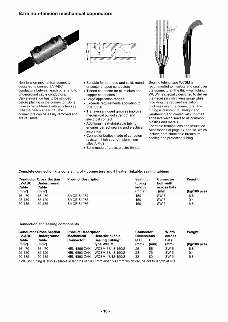
Bare non-tension mechanical connectors
Non-tension mechanical connector designed to connect LV-ABC conductors between each other and to underground cable conductors. Cable insulation has to be stripped before placing in the connector. Bolts have to be tightened with an allen key until the heads shear off. The connectors can be easily removed and are reusable.
• Suitable for stranded and solid, round or sector shaped conductors
• Tinned connector for aluminium and copper conductors
• Large application ranges • Exceeds requirements according to
VDE 0220 • Transversal ridged grooves improve
mechanical pullout strength and electrical contact
• Additional heat-shrinkable tubing ensures perfect sealing and electrical insulation
• Connector bodies made of corrosion resistant, high strength aluminium alloy AlMgSi
• Bolts made of brass, electro tinned
Sealing tubing type WCSM is recommeded to insulate and seal over the connectors. The thick-wall tubing WCSM is specially designed to deliver the necessary shrinking range while providing the required insulation thickness over the connectors. The tubing is resistant to UV-light and weathering and coated with hot-melt adhesive which seals to all common plastics and metals. For cable terminations see Insulation Accessories at page 17 and 18, which include heat-shrinkable breakouts, sealing and protection tubing.
Complete connection kits consisting of 4 connectors and 4 heat-shrinkable, sealing tubings Conductor Cross Section Product Description Sealing Connector Weight LV-ABC Underground tubing bolt width Cable Cable length across flats (mm²) (mm²) (mm) (mm) (kg/100 pcs) 16- 70 16- 70 SMOE-81974 150 SW 5 6,8 25-150 35-120 SMOE-81975 150 SW 6 9,4 50-185 50-185 SMOE-81976 150 SW 6 16,8 Connection and sealing components Conductor Cross Section Product Description Connector Width Weight LV-ABC Underground Mechanical Heat-shrinkable Dimensions across Cable Cable Connector Sealing Tubing* ∅ D L flats (mm²) (mm²) type WCSM (mm) (mm) (mm) (kg/100 pcs) 16- 70 16- 70 HEL-4896 ZAK WCSM-33/ 8-150/S 25 55 SW 5 6,8 25-150 35-120 HEL-6893 ZAK WCSM-33/ 8-150/S 28 75 SW 6 9,4 50-185 50-185 HEL-4893 ZAK WCSM-43/12-150/S 32 80 SW 6 16,8 * WCSM tubing is also available in lengths of 1000 mm and 1500 mm which can be cut to length at site.
- 17 -
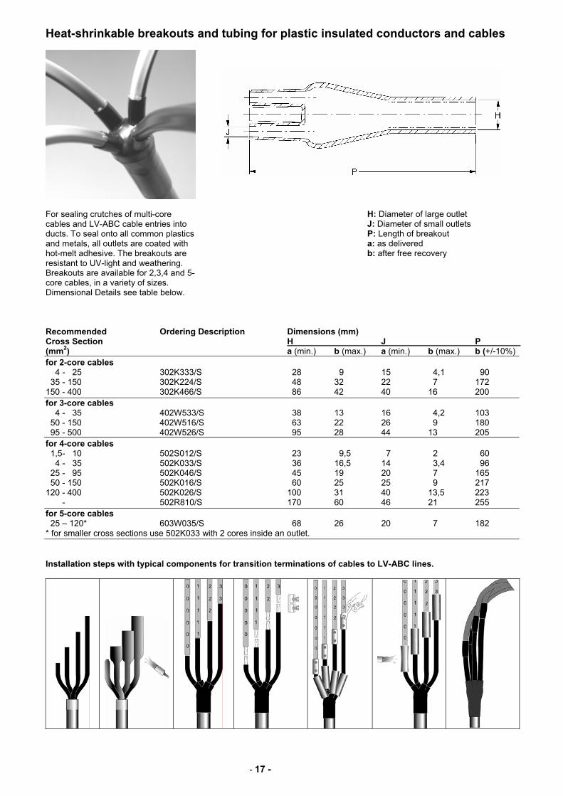
Heat-shrinkable breakouts and tubing for plastic insulated conductors and cables
For sealing crutches of multi-core cables and LV-ABC cable entries into ducts. To seal onto all common plastics and metals, all outlets are coated with hot-melt adhesive. The breakouts are resistant to UV-light and weathering. Breakouts are available for 2,3,4 and 5-core cables, in a variety of sizes. Dimensional Details see table below.
H: Diameter of large outlet J: Diameter of small outlets P: Length of breakout a: as delivered b: after free recovery
Recommended Ordering Description Dimensions (mm) Cross Section H J P (mm2) a (min.) b (max.) a (min.) b (max.) b (+/-10%) for 2-core cables 4 - 25 302K333/S 28 9 15 4,1 90 35 - 150 302K224/S 48 32 22 7 172 150 - 400 302K466/S 86 42 40 16 200 for 3-core cables 4 - 35 402W533/S 38 13 16 4,2 103 50 - 150 402W516/S 63 22 26 9 180 95 - 500 402W526/S 95 28 44 13 205 for 4-core cables 1,5- 10 502S012/S 23 9,5 7 2 60 4 - 35 502K033/S 36 16,5 14 3,4 96 25 - 95 502K046/S 45 19 20 7 165 50 - 150 502K016/S 60 25 25 9 217 120 - 400 502K026/S 100 31 40 13,5 223 - 502R810/S 170 60 46 21 255 for 5-core cables 25 – 120* 603W035/S 68 26 20 7 182 * for smaller cross sections use 502K033 with 2 cores inside an outlet. Installation steps with typical components for transition terminations of cables to LV-ABC lines.
- 18 -
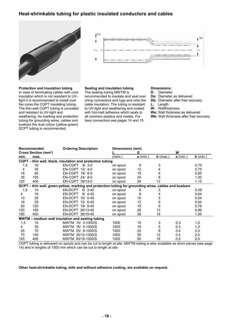
Heat-shrinkable tubing for plastic insulated conductors and cables
Protection and insulation tubing In case of terminating cables with core insulation which is not resistant to UV-light it is recommended to install over the cores the CGPT insulating tubing. The thin-wall CGPT tubing is uncoated and resistant to UV-light and weathering. As marking and protection tubing for grounding wires, cables and busbars the dual colour (yellow-green) DCPT tubing is recommended.
Sealing and insulation tubing The sealing tubing MWTM is recommended to insulate and seal over crimp connectors and lugs and onto the cable insulation. The tubing is resistant to UV-light and weathering and coated with hot-melt adhesive which seals to all common plastics and metals. For bare connectors see pages 14 and 15.
Dimensions: D: Diameter Da: Diameter as delivered Db: Diameter after free recovery L: Length W: Wallthickness Wa: Wall thickness as delivered Wb: Wall thickness after free recovery
Recommended Ordering Description Dimensions (mm) Cross Section (mm²) L D W min. max. (nom.) a (min.) b (max.) a (min.) b (min.) CGPT – thin wall, black, insulation and protection tubing 1,5 10 EN-CGPT 9/ 3-0 on spool 9 3 0,75 4 35 EN-CGPT 12/ 4-0 on spool 12 4 0,75 16 95 EN-CGPT 18/ 6-0 on spool 18 6 0,85 35 150 EN-CGPT 24/ 8-0 on spool 24 8 1,00 120 400 EN-CGPT 39/13-0 on spool 39 13 1,15 DCPT – thin wall, green-yellow, marking and protection tubing for grounding wires, cables and busbars 1,5 10 EN-DCPT 6/ 3-45 on spool 6 3 0,58 4 16 EN-DCPT 8/ 4-45 on spool 8 4 0,64 10 25 EN-DCPT 10/ 5-45 on spool 10 5 0,64 16 35 EN-DCPT 12/ 6-45 on spool 12 6 0,64 50 120 EN-DCPT 19/ 9-45 on spool 19 9 0,76 120 185 EN-DCPT 26/13-45 on spool 26 13 0,89 185 400 EN-DCPT 38/19-45 on spool 38 19 1,00 MWTM – medium wall insulation and sealing tubing 1,5 10 MWTM 10/ 3-1000/S 1000 10 3 0,3 1,0 4 35 MWTM 16/ 5-1000/S 1000 16 5 0,3 1,4 25 70 MWTM 25/ 8-1000/S 1000 25 8 0,4 2,0 70 150 MWTM 35/12-1000/S 1000 35 12 0,4 2,0 150 400 MWTM 50/16-1000/S 1000 50 16 0,5 2,0 CGPT tubing is delivered on spools and can be cut to length at site. MWTM tubing is also available as short pieces (see page 14) and in lengths of 1500 mm which can be cut to length at site Other heat-shrinkable tubing, with and without adhesive coating, are available on request.
- 19 -
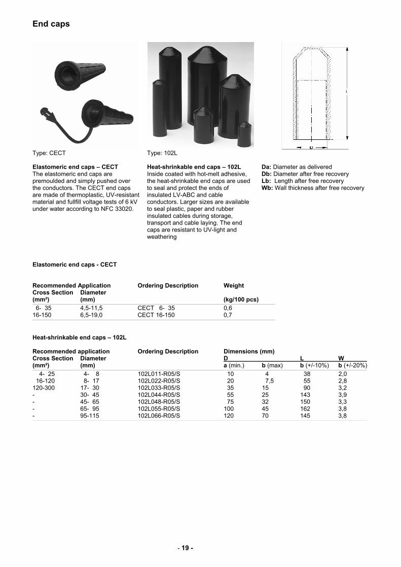
End caps
Type: CECT Type: 102L
Elastomeric end caps – CECT The elastomeric end caps are premoulded and simply pushed over the conductors. The CECT end caps are made of thermoplastic, UV-resistant material and fullfill voltage tests of 6 kV under water according to NFC 33020.
Heat-shrinkable end caps – 102L Inside coated with hot-melt adhesive, the heat-shrinkable end caps are used to seal and protect the ends of insulated LV-ABC and cable conductors. Larger sizes are available to seal plastic, paper and rubber insulated cables during storage, transport and cable laying. The end caps are resistant to UV-light and weathering
Da: Diameter as delivered Db: Diameter after free recovery Lb: Length after free recovery Wb: Wall thickness after free recovery
Elastomeric end caps - CECT Recommended Application Ordering Description Weight Cross Section Diameter (mm²) (mm) (kg/100 pcs)
6- 35 4,5-11,5 CECT 6- 35 0,6 16-150 6,5-19,0 CECT 16-150 0,7
Heat-shrinkable end caps – 102L Recommended application Ordering Description Dimensions (mm) Cross Section Diameter D L W (mm²) (mm) a (min.) b (max) b (+/-10%) b (+/-20%)
4- 25 4- 8 102L011-R05/S 10 4 38 2,0 16-120 8- 17 102L022-R05/S 20 7,5 55 2,8 120-300 17- 30 102L033-R05/S 35 15 90 3,2 - 30- 45 102L044-R05/S 55 25 143 3,9 - 45- 65 102L048-R05/S 75 32 150 3,3 - 65- 95 102L055-R05/S 100 45 162 3,8 - 95-115 102L066-R05/S 120 70 145 3,8
- 20 -
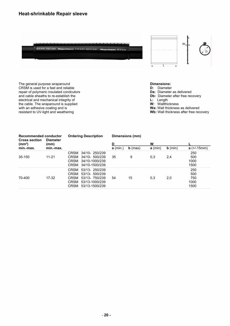
Heat-shrinkable Repair sleeve
The general purpose wraparound CRSM is used for a fast and reliable repair of polymeric insulated condcutors and cable sheaths to re-establish the electrical and mechanical integrity of the cable. The wraparound is supplied with an adhesive coating and is resistant to UV-light and weathering
Dimensions: D: Diameter Da: Diameter as delivered Db: Diameter after free recovery L: Length W: Wallthickness Wa: Wall thickness as delivered Wb: Wall thickness after free recovery
Recommended conductor Ordering Description Dimensions (mm) Cross section Diameter (mm²) (mm) D W L min.-max. min.-max. a (min.) b (max) a (min) b (min) a (+/-15mm)
CRSM 34/10- 250/239 250 35-150 11-21 CRSM 34/10- 500/239 35 9 0,3 2,4 500 CRSM 34/10-1000/239 1000 CRSM 34/10-1500/239 1500
CRSM 53/13- 250/239 250 CRSM 53/13- 500/239 500 70-400 17-32 CRSM 53/13- 750/239 54 15 0,3 2,0 750 CRSM 53/13-1000/239 1000 CRSM 53/13-1500/239 1500
- 21 -
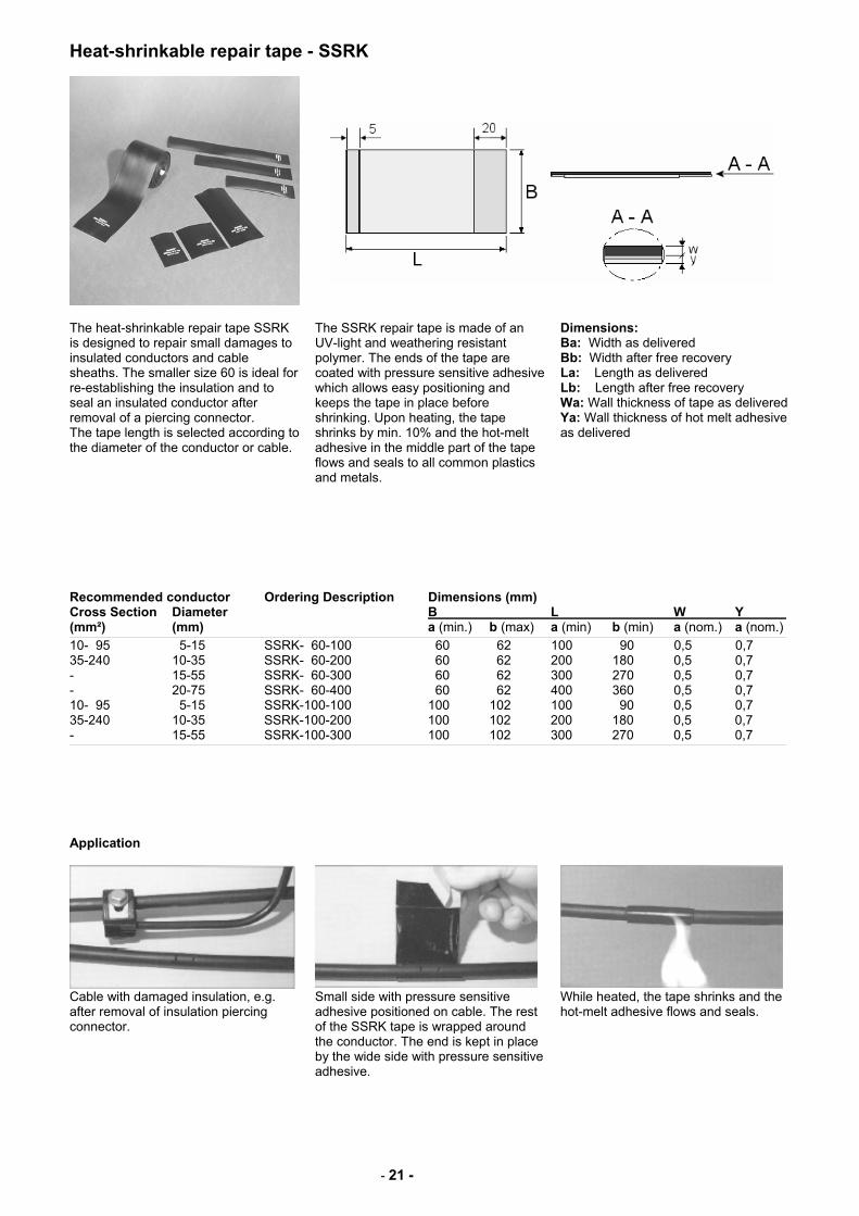
Heat-shrinkable repair tape - SSRK
The heat-shrinkable repair tape SSRK is designed to repair small damages to insulated conductors and cable sheaths. The smaller size 60 is ideal for re-establishing the insulation and to seal an insulated conductor after removal of a piercing connector. The tape length is selected according to the diameter of the conductor or cable.
The SSRK repair tape is made of an UV-light and weathering resistant polymer. The ends of the tape are coated with pressure sensitive adhesive which allows easy positioning and keeps the tape in place before shrinking. Upon heating, the tape shrinks by min. 10% and the hot-melt adhesive in the middle part of the tape flows and seals to all common plastics and metals.
Dimensions: Ba: Width as delivered Bb: Width after free recovery La: Length as delivered Lb: Length after free recovery Wa: Wall thickness of tape as delivered Ya: Wall thickness of hot melt adhesive as delivered
Recommended conductor Ordering Description Dimensions (mm) Cross Section Diameter B L W Y (mm²) (mm) a (min.) b (max) a (min) b (min) a (nom.) a (nom.)
10- 95 5-15 SSRK- 60-100 60 62 100 90 0,5 0,7 35-240 10-35 SSRK- 60-200 60 62 200 180 0,5 0,7 - 15-55 SSRK- 60-300 60 62 300 270 0,5 0,7 - 20-75 SSRK- 60-400 60 62 400 360 0,5 0,7 10- 95 5-15 SSRK-100-100 100 102 100 90 0,5 0,7 35-240 10-35 SSRK-100-200 100 102 200 180 0,5 0,7 - 15-55 SSRK-100-300 100 102 300 270 0,5 0,7
Application
Cable with damaged insulation, e.g. after removal of insulation piercing connector.
Small side with pressure sensitive adhesive positioned on cable. The rest of the SSRK tape is wrapped around the conductor. The end is kept in place by the wide side with pressure sensitive adhesive.
While heated, the tape shrinks and the hot-melt adhesive flows and seals.
- 22 -
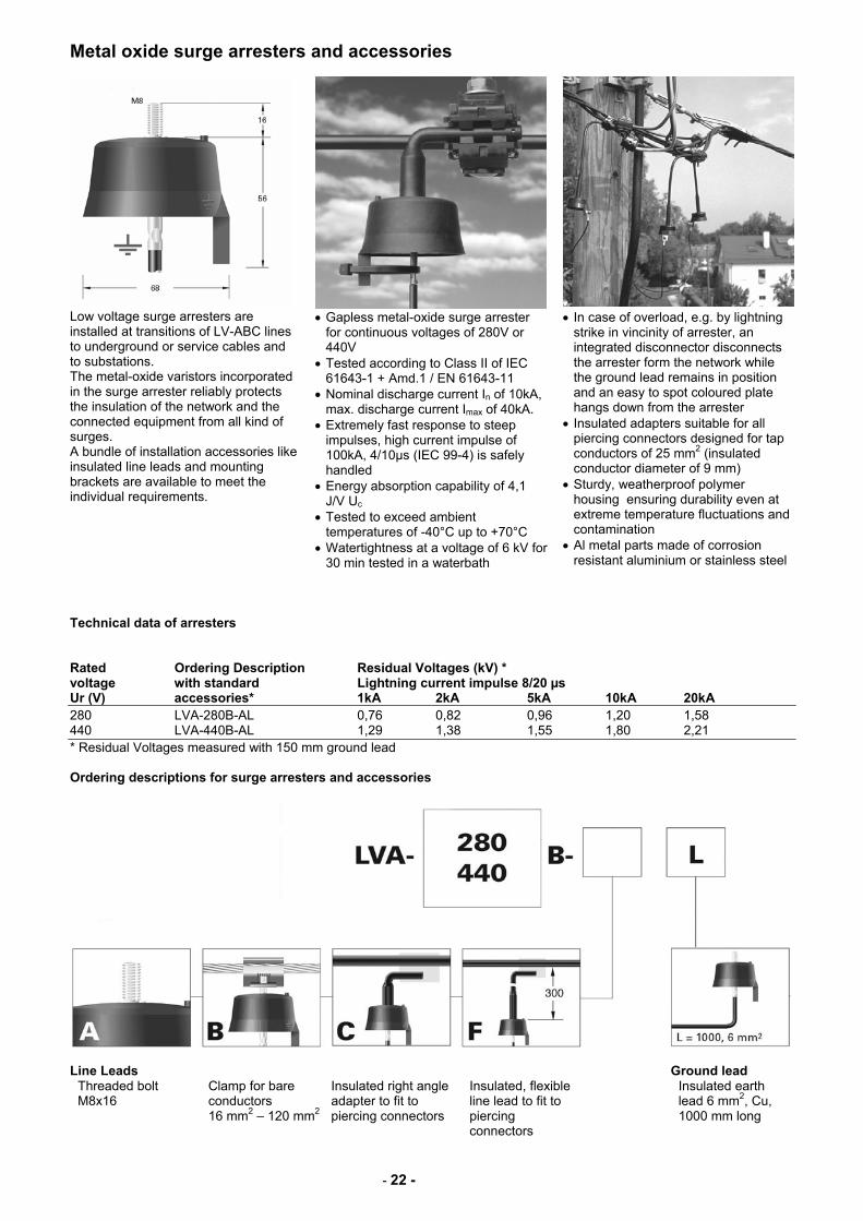
Metal oxide surge arresters and accessories
Low voltage surge arresters are installed at transitions of LV-ABC lines to underground or service cables and to substations. The metal-oxide varistors incorporated in the surge arrester reliably protects the insulation of the network and the connected equipment from all kind of surges. A bundle of installation accessories like insulated line leads and mounting brackets are available to meet the individual requirements.
• Gapless metal-oxide surge arrester for continuous voltages of 280V or 440V
• Tested according to Class II of IEC 61643-1 + Amd.1 / EN 61643-11
• Nominal discharge current In of 10kA, max. discharge current Imax of 40kA.
• Extremely fast response to steep impulses, high current impulse of 100kA, 4/10µs (IEC 99-4) is safely handled
• Energy absorption capability of 4,1 J/V Uc
• Tested to exceed ambient temperatures of -40°C up to +70°C
• Watertightness at a voltage of 6 kV for 30 min tested in a waterbath
• In case of overload, e.g. by lightning strike in vincinity of arrester, an integrated disconnector disconnects the arrester form the network while the ground lead remains in position and an easy to spot coloured plate hangs down from the arrester
• Insulated adapters suitable for all piercing connectors designed for tap conductors of 25 mm2 (insulated conductor diameter of 9 mm)
• Sturdy, weatherproof polymer housing ensuring durability even at extreme temperature fluctuations and contamination
• Al metal parts made of corrosion resistant aluminium or stainless steel
Technical data of arresters Rated Ordering Description Residual Voltages (kV) * voltage with standard Lightning current impulse 8/20 µs Ur (V) accessories* 1kA 2kA 5kA 10kA 20kA 280 LVA-280B-AL 0,76 0,82 0,96 1,20 1,58 440 LVA-440B-AL 1,29 1,38 1,55 1,80 2,21 * Residual Voltages measured with 150 mm ground lead Ordering descriptions for surge arresters and accessories
Line Leads Ground lead
Threaded bolt M8x16
Clamp for bare conductors 16 mm2 – 120 mm2
Insulated right angle adapter to fit to piercing connectors
Insulated, flexible line lead to fit to piercing connectors
Insulated earth lead 6 mm2, Cu, 1000 mm long
- 23 -
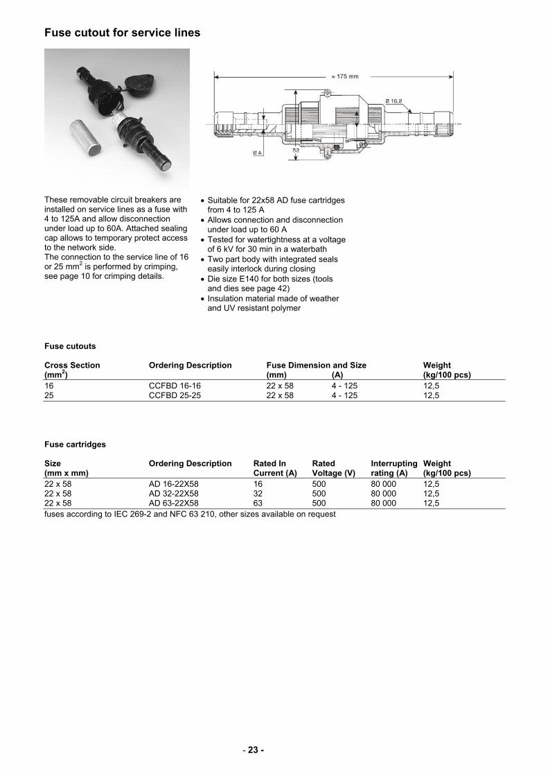
Fuse cutout for service lines
These removable circuit breakers are installed on service lines as a fuse with 4 to 125A and allow disconnection under load up to 60A. Attached sealing cap allows to temporary protect access to the network side. The connection to the service line of 16 or 25 mm2 is performed by crimping, see page 10 for crimping details.
• Suitable for 22x58 AD fuse cartridges from 4 to 125 A
• Allows connection and disconnection under load up to 60 A
• Tested for watertightness at a voltage of 6 kV for 30 min in a waterbath
• Two part body with integrated seals easily interlock during closing
• Die size E140 for both sizes (tools and dies see page 42)
• Insulation material made of weather and UV resistant polymer
Fuse cutouts Cross Section Ordering Description Fuse Dimension and Size Weight (mm2) (mm) (A) (kg/100 pcs) 16 CCFBD 16-16 22 x 58 4 - 125 12,5 25 CCFBD 25-25 22 x 58 4 - 125 12,5 Fuse cartridges Size Ordering Description Rated In Rated Interrupting Weight (mm x mm) Current (A) Voltage (V) rating (A) (kg/100 pcs) 22 x 58 AD 16-22X58 16 500 80 000 12,5 22 x 58 AD 32-22X58 32 500 80 000 12,5 22 x 58 AD 63-22X58 63 500 80 000 12,5 fuses according to IEC 269-2 and NFC 63 210, other sizes available on request
- 24 -
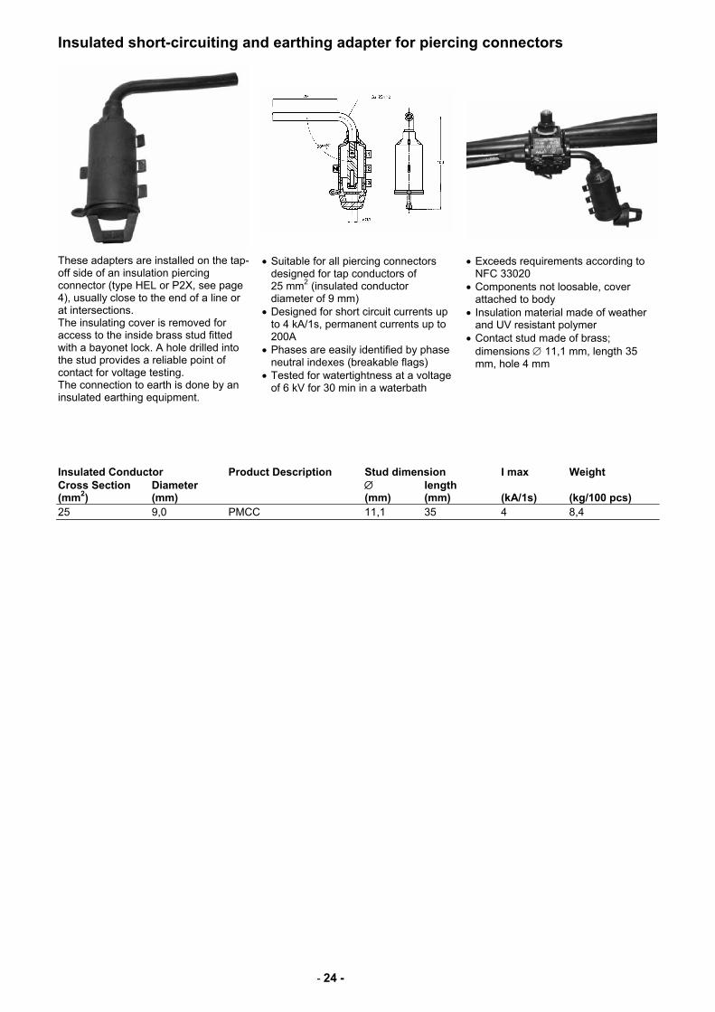
Insulated short-circuiting and earthing adapter for piercing connectors
These adapters are installed on the tap-off side of an insulation piercing connector (type HEL or P2X, see page 4), usually close to the end of a line or at intersections. The insulating cover is removed for access to the inside brass stud fitted with a bayonet lock. A hole drilled into the stud provides a reliable point of contact for voltage testing. The connection to earth is done by an insulated earthing equipment.
• Suitable for all piercing connectors designed for tap conductors of 25 mm2 (insulated conductor diameter of 9 mm)
• Designed for short circuit currents up to 4 kA/1s, permanent currents up to 200A
• Phases are easily identified by phase neutral indexes (breakable flags)
• Tested for watertightness at a voltage of 6 kV for 30 min in a waterbath
• Exceeds requirements according to NFC 33020
• Components not loosable, cover attached to body
• Insulation material made of weather and UV resistant polymer
• Contact stud made of brass; dimensions ∅ 11,1 mm, length 35 mm, hole 4 mm
Insulated Conductor Product Description Stud dimension I max Weight Cross Section Diameter ∅ length (mm2) (mm) (mm) (mm) (kA/1s) (kg/100 pcs) 25 9,0 PMCC 11,1 35 4 8,4
- 25 -
Short-circuiting and earthing equipment
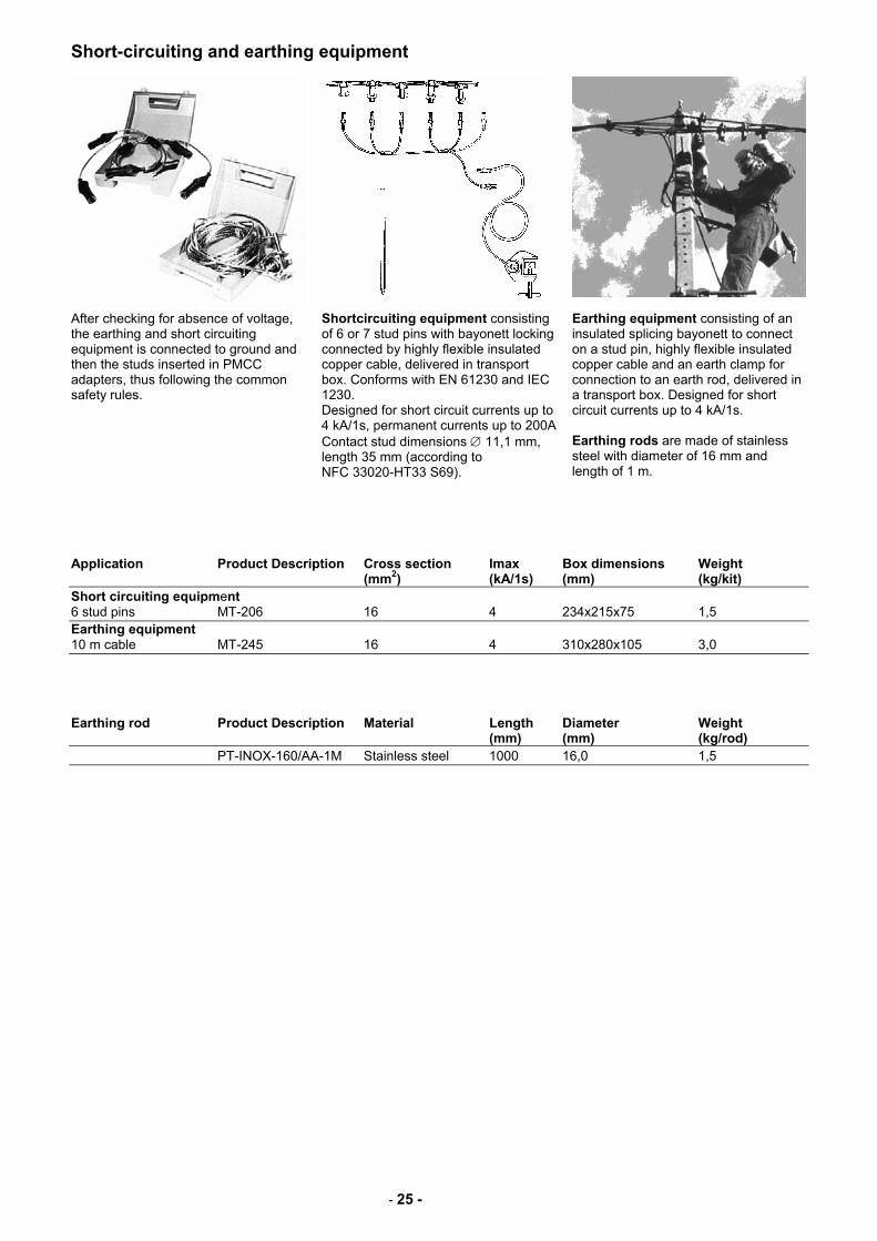
After checking for absence of voltage, the earthing and short circuiting equipment is connected to ground and then the studs inserted in PMCC adapters, thus following the common safety rules.
Shortcircuiting equipment consisting of 6 or 7 stud pins with bayonett locking connected by highly flexible insulated copper cable, delivered in transport box. Conforms with EN 61230 and IEC 1230. Designed for short circuit currents up to 4 kA/1s, permanent currents up to 200A Contact stud dimensions ∅ 11,1 mm, length 35 mm (according to NFC 33020-HT33 S69).
Earthing equipment consisting of an insulated splicing bayonett to connect on a stud pin, highly flexible insulated copper cable and an earth clamp for connection to an earth rod, delivered in a transport box. Designed for short circuit currents up to 4 kA/1s. Earthing rods are made of stainless steel with diameter of 16 mm and length of 1 m.
Application Product Description Cross section Imax Box dimensions Weight (mm2) (kA/1s) (mm) (kg/kit) Short circuiting equipment 6 stud pins MT-206 16 4 234x215x75 1,5 Earthing equipment 10 m cable MT-245 16 4 310x280x105 3,0 Earthing rod Product Description Material Length Diameter Weight (mm) (mm) (kg/rod) PT-INOX-160/AA-1M Stainless steel 1000 16,0 1,5
- 26 -
Anchor and angle clamps for service cables
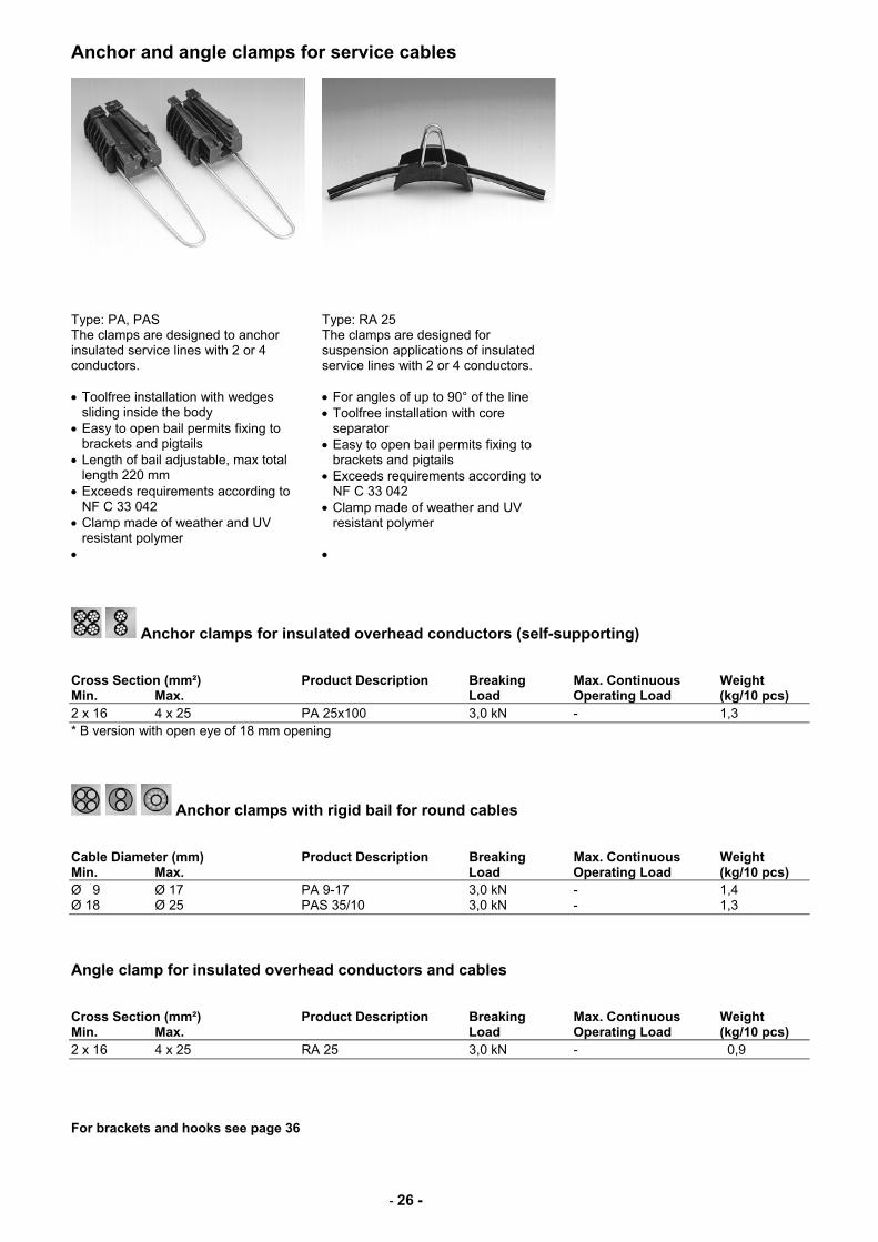
Type: PA, PAS Type: RA 25 The clamps are designed to anchor insulated service lines with 2 or 4 conductors. • Toolfree installation with wedges
sliding inside the body • Easy to open bail permits fixing to
brackets and pigtails • Length of bail adjustable, max total
length 220 mm • Exceeds requirements according to
NF C 33 042 • Clamp made of weather and UV
resistant polymer •
The clamps are designed for suspension applications of insulated service lines with 2 or 4 conductors. • For angles of up to 90° of the line • Toolfree installation with core
separator • Easy to open bail permits fixing to
brackets and pigtails • Exceeds requirements according to
NF C 33 042 • Clamp made of weather and UV
resistant polymer •
Anchor clamps for insulated overhead conductors (self-supporting) Cross Section (mm²) Product Description Breaking Max. Continuous Weight Min. Max. Load Operating Load (kg/10 pcs) 2 x 16 4 x 25 PA 25x100 3,0 kN - 1,3 * B version with open eye of 18 mm opening
Anchor clamps with rigid bail for round cables Cable Diameter (mm) Product Description Breaking Max. Continuous Weight Min. Max. Load Operating Load (kg/10 pcs) Ø 9 Ø 17 PA 9-17 3,0 kN - 1,4 Ø 18 Ø 25 PAS 35/10 3,0 kN - 1,3 Angle clamp for insulated overhead conductors and cables Cross Section (mm²) Product Description Breaking Max. Continuous Weight Min. Max. Load Operating Load (kg/10 pcs) 2 x 16 4 x 25 RA 25 3,0 kN - 0,9 For brackets and hooks see page 36
- 27 -
Anchor and suspension clamps for service cables
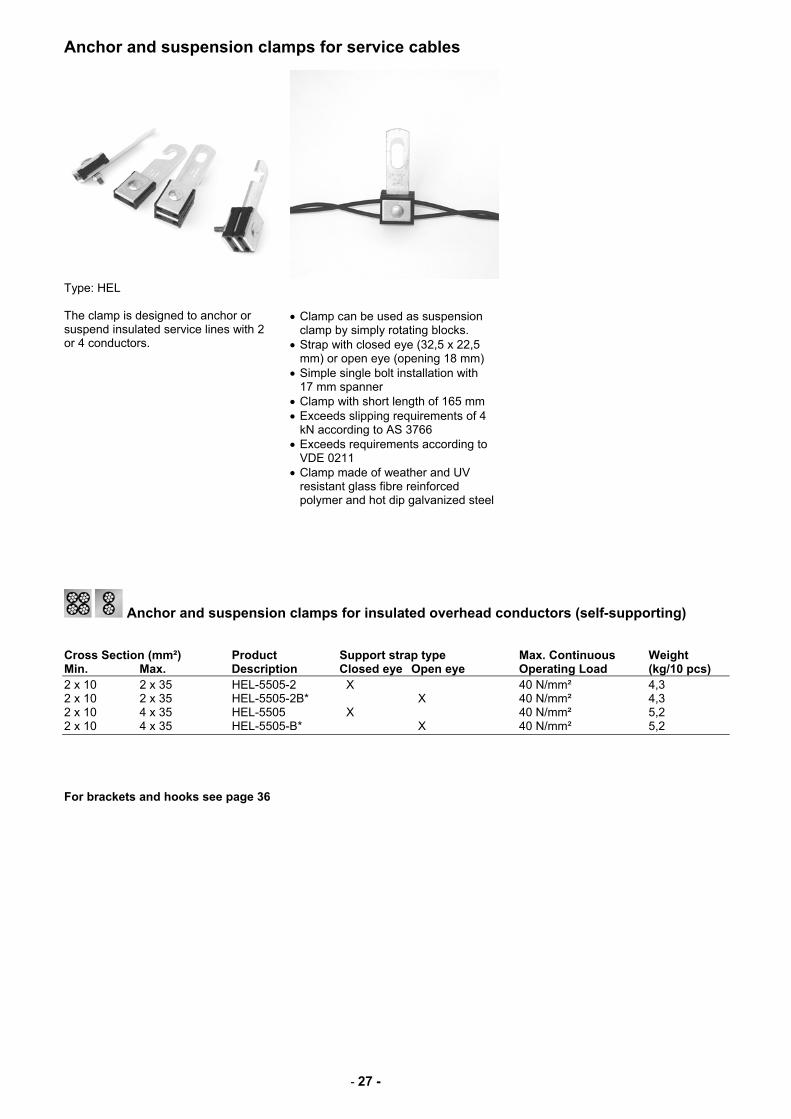
Type: HEL
The clamp is designed to anchor or suspend insulated service lines with 2 or 4 conductors.
• Clamp can be used as suspension clamp by simply rotating blocks.
• Strap with closed eye (32,5 x 22,5 mm) or open eye (opening 18 mm)
• Simple single bolt installation with 17 mm spanner
• Clamp with short length of 165 mm • Exceeds slipping requirements of 4
kN according to AS 3766 • Exceeds requirements according to
VDE 0211 • Clamp made of weather and UV
resistant glass fibre reinforced polymer and hot dip galvanized steel
Anchor and suspension clamps for insulated overhead conductors (self-supporting) Cross Section (mm²) Product Support strap type Max. Continuous Weight Min. Max. Description Closed eye Open eye Operating Load (kg/10 pcs) 2 x 10 2 x 35 HEL-5505-2 X 40 N/mm² 4,3 2 x 10 2 x 35 HEL-5505-2B* X 40 N/mm² 4,3 2 x 10 4 x 35 HEL-5505 X 40 N/mm² 5,2 2 x 10 4 x 35 HEL-5505-B* X 40 N/mm² 5,2 For brackets and hooks see page 36
- 28 -
Anchoring clamps for self supporting LV-ABC lines
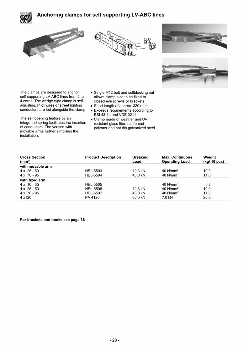
The clamps are designed to anchor self supporting LV-ABC lines from 2 to 4 cores. The wedge type clamp is self-adjusting. Pilot wires or street lighting conductors are led alongside the clamp. The self opening feature by an integrated spring facilitates the insertion of conductors. The version with movable arms further simplifies the installation.
• Single M12 bolt and selfblocking nut allows clamp also to be fixed to closed eye screws or brackets
• Short length of approx. 320 mm • Exceeds requirements according to
ESI 43-14 and VDE 0211 • Clamp made of weather and UV
resistant glass fibre reinforced polymer and hot dip galvanized steel
Cross Section Product Description Breaking Max. Continuous Weight (mm²) Load Operating Load (kg/ 10 pcs) with movable arm 4 x 25 - 50 HEL-5503 12,3 kN 40 N/mm² 10,0 4 x 70 - 95 HEL-5504 43,0 kN 40 N/mm² 11,0 with fixed arm 4 x 10 - 35 HEL-5505 40 N/mm² 5,2 4 x 25 - 50 HEL-5506 12,3 kN 40 N/mm² 10,0 4 x 70 - 95 HEL-5507 43,0 kN 40 N/mm² 11,0 4 x120 PA 4120 60,0 kN 7,0 kN 20,0 For brackets and hooks see page 36
- 29 -
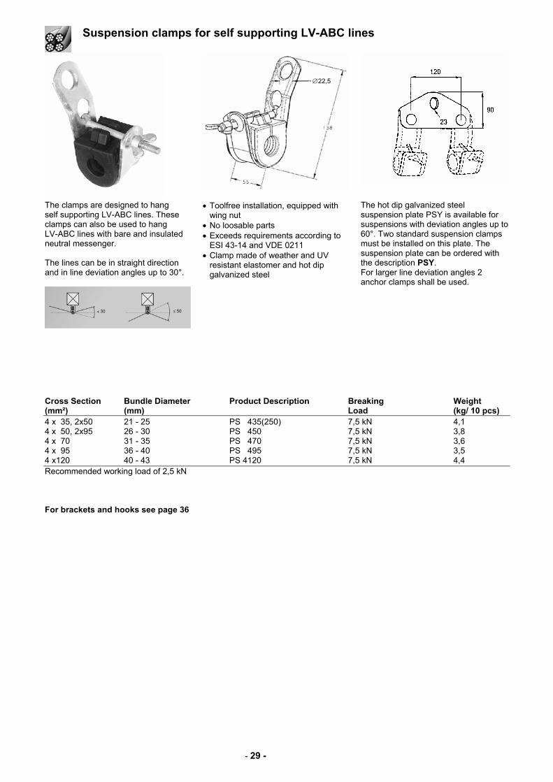
Suspension clamps for self supporting LV-ABC lines
The clamps are designed to hang self supporting LV-ABC lines. These clamps can also be used to hang LV-ABC lines with bare and insulated neutral messenger. The lines can be in straight direction and in line deviation angles up to 30°.
• Toolfree installation, equipped with wing nut
• No loosable parts • Exceeds requirements according to
ESI 43-14 and VDE 0211 • Clamp made of weather and UV
resistant elastomer and hot dip galvanized steel
The hot dip galvanized steel suspension plate PSY is available for suspensions with deviation angles up to 60°. Two standard suspension clamps must be installed on this plate. The suspension plate can be ordered with the description PSY. For larger line deviation angles 2 anchor clamps shall be used.
Cross Section Bundle Diameter Product Description Breaking Weight (mm²) (mm) Load (kg/ 10 pcs) 4 x 35, 2x50 21 - 25 PS 435(250) 7,5 kN 4,1 4 x 50, 2x95 26 - 30 PS 450 7,5 kN 3,8 4 x 70 31 - 35 PS 470 7,5 kN 3,6 4 x 95 36 - 40 PS 495 7,5 kN 3,5 4 x120 40 - 43 PS 4120 7,5 kN 4,4 Recommended working load of 2,5 kN For brackets and hooks see page 36
∅22,5
- 30 -
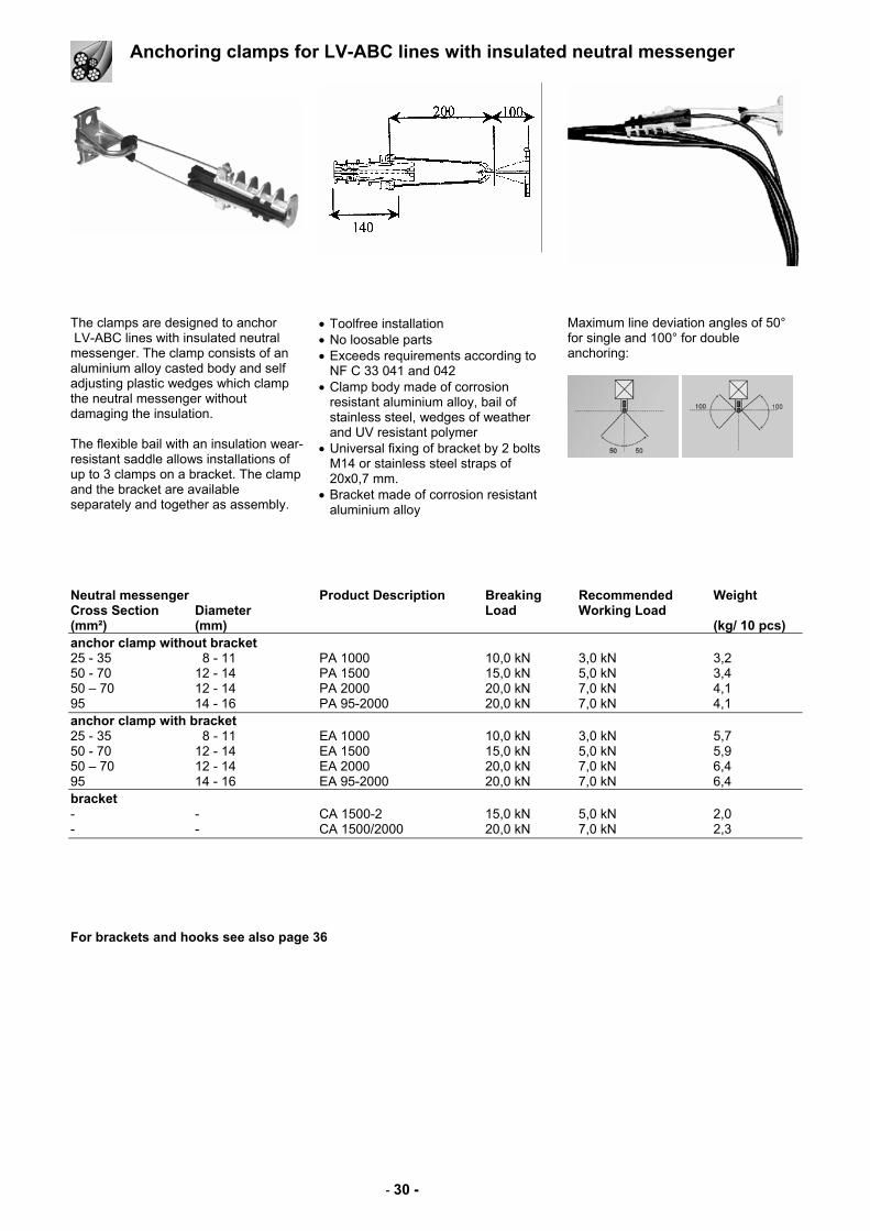
Anchoring clamps for LV-ABC lines with insulated neutral messenger
The clamps are designed to anchor LV-ABC lines with insulated neutral messenger. The clamp consists of an aluminium alloy casted body and self adjusting plastic wedges which clamp the neutral messenger without damaging the insulation. The flexible bail with an insulation wear-resistant saddle allows installations of up to 3 clamps on a bracket. The clamp and the bracket are available separately and together as assembly.
• Toolfree installation • No loosable parts • Exceeds requirements according to
NF C 33 041 and 042 • Clamp body made of corrosion
resistant aluminium alloy, bail of stainless steel, wedges of weather and UV resistant polymer
• Universal fixing of bracket by 2 bolts M14 or stainless steel straps of 20x0,7 mm.
• Bracket made of corrosion resistant aluminium alloy
Maximum line deviation angles of 50° for single and 100° for double anchoring:
Neutral messenger Product Description Breaking Recommended Weight Cross Section Diameter Load Working Load (mm²) (mm) (kg/ 10 pcs) anchor clamp without bracket 25 - 35 8 - 11 PA 1000 10,0 kN 3,0 kN 3,2 50 - 70 12 - 14 PA 1500 15,0 kN 5,0 kN 3,4 50 – 70 12 - 14 PA 2000 20,0 kN 7,0 kN 4,1 95 14 - 16 PA 95-2000 20,0 kN 7,0 kN 4,1 anchor clamp with bracket 25 - 35 8 - 11 EA 1000 10,0 kN 3,0 kN 5,7 50 - 70 12 - 14 EA 1500 15,0 kN 5,0 kN 5,9 50 – 70 12 - 14 EA 2000 20,0 kN 7,0 kN 6,4 95 14 - 16 EA 95-2000 20,0 kN 7,0 kN 6,4 bracket - - CA 1500-2 15,0 kN 5,0 kN 2,0 - - CA 1500/2000 20,0 kN 7,0 kN 2,3 For brackets and hooks see also page 36
- 31 -
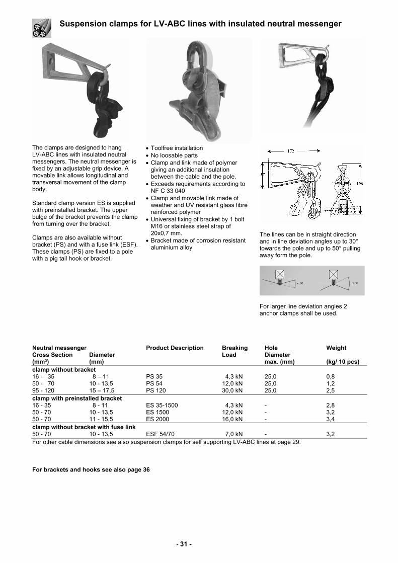
Suspension clamps for LV-ABC lines with insulated neutral messenger
The clamps are designed to hang LV-ABC lines with insulated neutral messengers. The neutral messenger is fixed by an adjustable grip device. A movable link allows longitudinal and transversal movement of the clamp body. Standard clamp version ES is supplied with preinstalled bracket. The upper bulge of the bracket prevents the clamp from turning over the bracket. Clamps are also available without bracket (PS) and with a fuse link (ESF). These clamps (PS) are fixed to a pole with a pig tail hook or bracket.
• Toolfree installation • No loosable parts • Clamp and link made of polymer
giving an additional insulation between the cable and the pole.
• Exceeds requirements according to NF C 33 040
• Clamp and movable link made of weather and UV resistant glass fibre reinforced polymer
• Universal fixing of bracket by 1 bolt M16 or stainless steel strap of 20x0,7 mm.
• Bracket made of corrosion resistant aluminium alloy
The lines can be in straight direction and in line deviation angles up to 30° towards the pole and up to 50° pulling away form the pole.
For larger line deviation angles 2 anchor clamps shall be used.
Neutral messenger Product Description Breaking Hole Weight Cross Section Diameter Load Diameter (mm²) (mm) max. (mm) (kg/ 10 pcs) clamp without bracket 16 - 35 8 – 11 PS 35 4,3 kN 25,0 0,8 50 - 70 10 - 13,5 PS 54 12,0 kN 25,0 1,2 95 - 120 15 – 17,5 PS 120 30,0 kN 25,0 2,5 clamp with preinstalled bracket 16 - 35 8 - 11 ES 35-1500 4,3 kN - 2,8 50 - 70 10 - 13,5 ES 1500 12,0 kN - 3,2 50 - 70 11 - 15,5 ES 2000 16,0 kN - 3,4 clamp without bracket with fuse link 50 - 70 10 - 13,5 ESF 54/70 7,0 kN - 3,2 For other cable dimensions see also suspension clamps for self supporting LV-ABC lines at page 29. For brackets and hooks see also page 36
- 32 -
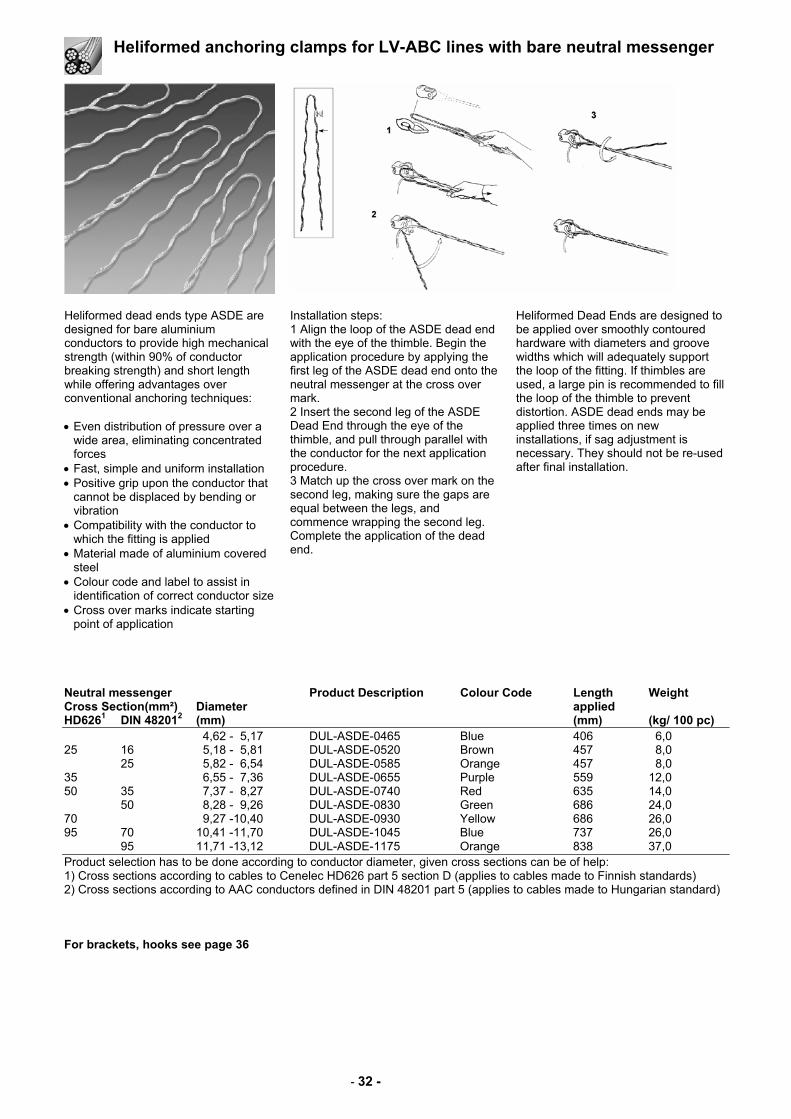
Heliformed anchoring clamps for LV-ABC lines with bare neutral messenger
Heliformed dead ends type ASDE are designed for bare aluminium conductors to provide high mechanical strength (within 90% of conductor breaking strength) and short length while offering advantages over conventional anchoring techniques: • Even distribution of pressure over a
wide area, eliminating concentrated forces
• Fast, simple and uniform installation • Positive grip upon the conductor that
cannot be displaced by bending or vibration
• Compatibility with the conductor to which the fitting is applied
• Material made of aluminium covered steel
• Colour code and label to assist in identification of correct conductor size
• Cross over marks indicate starting point of application
Installation steps: 1 Align the loop of the ASDE dead end with the eye of the thimble. Begin the application procedure by applying the first leg of the ASDE dead end onto the neutral messenger at the cross over mark. 2 Insert the second leg of the ASDE Dead End through the eye of the thimble, and pull through parallel with the conductor for the next application procedure. 3 Match up the cross over mark on the second leg, making sure the gaps are equal between the legs, and commence wrapping the second leg. Complete the application of the dead end.
Heliformed Dead Ends are designed to be applied over smoothly contoured hardware with diameters and groove widths which will adequately support the loop of the fitting. If thimbles are used, a large pin is recommended to fill the loop of the thimble to prevent distortion. ASDE dead ends may be applied three times on new installations, if sag adjustment is necessary. They should not be re-used after final installation.
Neutral messenger Product Description Colour Code Length Weight Cross Section(mm²) Diameter applied HD6261 DIN 482012 (mm) (mm) (kg/ 100 pc) 4,62 - 5,17 DUL-ASDE-0465 Blue 406 6,0 25 16 5,18 - 5,81 DUL-ASDE-0520 Brown 457 8,0 25 5,82 - 6,54 DUL-ASDE-0585 Orange 457 8,0 35 6,55 - 7,36 DUL-ASDE-0655 Purple 559 12,0 50 35 7,37 - 8,27 DUL-ASDE-0740 Red 635 14,0 50 8,28 - 9,26 DUL-ASDE-0830 Green 686 24,0 70 9,27 -10,40 DUL-ASDE-0930 Yellow 686 26,0 95 70 10,41 -11,70 DUL-ASDE-1045 Blue 737 26,0 95 11,71 -13,12 DUL-ASDE-1175 Orange 838 37,0 Product selection has to be done according to conductor diameter, given cross sections can be of help: 1) Cross sections according to cables to Cenelec HD626 part 5 section D (applies to cables made to Finnish standards) 2) Cross sections according to AAC conductors defined in DIN 48201 part 5 (applies to cables made to Hungarian standard) For brackets, hooks see page 36
- 33 -
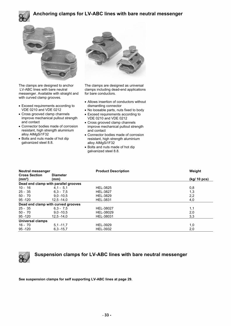
Anchoring clamps for LV-ABC lines with bare neutral messenger
The clamps are designed to anchor LV-ABC lines with bare neutral messenger. Available with straight and with curved clamp grooves. • Exceed requirements according to
VDE 0210 and VDE 0212 • Cross grooved clamp channels
improve mechanical pullout strength and contact
• Connector bodies made of corrosion resistant, high strength aluminium alloy AlMgSi1F32
• Bolts and nuts made of hot dip galvanized steel 8.8.
The clamps are designed as universal clamps including dead-end applications for bare conductors. • Allows insertion of conductors without
dismantling connector • No loosable parts, nuts fixed to body • Exceed requirements according to
VDE 0210 and VDE 0212 • Cross grooved clamp channels
improve mechanical pullout strength and contact
• Connector bodies made of corrosion resistant, high strength aluminium alloy AlMgSi1F32
• Bolts and nuts made of hot dip galvanized steel 8.8.
Neutral messenger Product Description Weight Cross Section Diameter (mm²) (mm) (kg/ 10 pcs) Dead end clamp with parallel grooves 10 - 16 4,1 - 5,1 HEL-3825 0,8 25 - 35 6,3 - 7,5 HEL-3827 1,3 50 - 70 9,0 -10,5 HEL-3829 2,2 95 -120 12,5 -14,0 HEL-3831 4,0 Dead end clamp with curved grooves 25 - 35 6,3 - 7,5 HEL-38027 1,1 50 - 70 9,0 -10,5 HEL-38029 2,0 95 -120 12,5 -14,0 HEL-38031 3,3 Universal clamps 16 - 70 5,1 -11,7 HEL-3929 1,0 95 -120 6,3 -15,7 HEL-3932 2,0
Suspension clamps for LV-ABC lines with bare neutral messenger
See suspension clamps for self supporting LV-ABC lines at page 29.
- 34 -
Wall mounted saddles and cable ties for LV-ABC lines
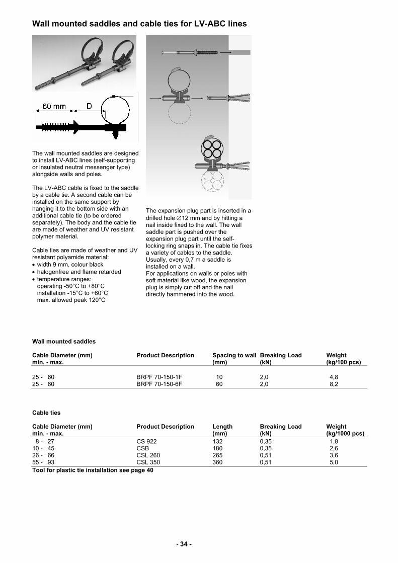
The wall mounted saddles are designed to install LV-ABC lines (self-supporting or insulated neutral messenger type) alongside walls and poles. The LV-ABC cable is fixed to the saddle by a cable tie. A second cable can be installed on the same support by hanging it to the bottom side with an additional cable tie (to be ordered separately). The body and the cable tie are made of weather and UV resistant polymer material. Cable ties are made of weather and UV resistant polyamide material: • width 9 mm, colour black • halogenfree and flame retarded • temperature ranges:
operating -50°C to +80°C installation -15°C to +60°C max. allowed peak 120°C
The expansion plug part is inserted in a drilled hole ∅12 mm and by hitting a nail inside fixed to the wall. The wall saddle part is pushed over the expansion plug part until the self-locking ring snaps in. The cable tie fixes a variety of cables to the saddle. Usually, every 0,7 m a saddle is installed on a wall. For applications on walls or poles with soft material like wood, the expansion plug is simply cut off and the nail directly hammered into the wood.
Wall mounted saddles Cable Diameter (mm) Product Description Spacing to wall Breaking Load Weight min. - max. (mm) (kN) (kg/100 pcs) 25 - 60 BRPF 70-150-1F 10 2,0 4,8 25 - 60 BRPF 70-150-6F 60 2,0 8,2 Cable ties Cable Diameter (mm) Product Description Length Breaking Load Weight min. - max. (mm) (kN) (kg/1000 pcs) 8 - 27 CS 922 132 0,35 1,8 10 - 45 CSB 180 0,35 2,6 26 - 66 CSL 260 265 0,51 3,6 55 - 93 CSL 350 360 0,51 5,0 Tool for plastic tie installation see page 40
- 35 -
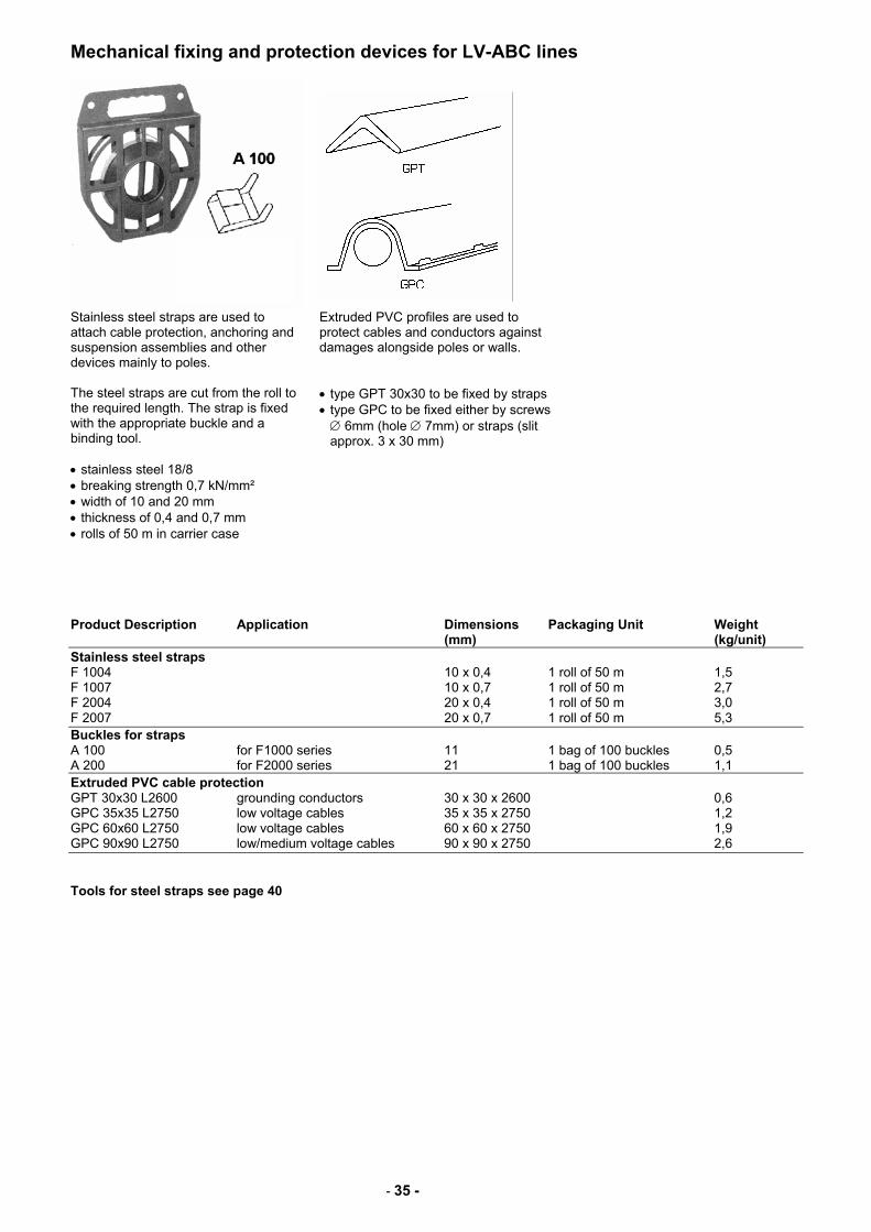
Mechanical fixing and protection devices for LV-ABC lines
Stainless steel straps are used to attach cable protection, anchoring and suspension assemblies and other devices mainly to poles. The steel straps are cut from the roll to the required length. The strap is fixed with the appropriate buckle and a binding tool. • stainless steel 18/8 • breaking strength 0,7 kN/mm² • width of 10 and 20 mm • thickness of 0,4 and 0,7 mm • rolls of 50 m in carrier case
Extruded PVC profiles are used to protect cables and conductors against damages alongside poles or walls. • type GPT 30x30 to be fixed by straps • type GPC to be fixed either by screws ∅ 6mm (hole ∅ 7mm) or straps (slit approx. 3 x 30 mm)
Product Description Application Dimensions Packaging Unit Weight (mm) (kg/unit) Stainless steel straps F 1004 10 x 0,4 1 roll of 50 m 1,5 F 1007 10 x 0,7 1 roll of 50 m 2,7 F 2004 20 x 0,4 1 roll of 50 m 3,0 F 2007 20 x 0,7 1 roll of 50 m 5,3 Buckles for straps A 100 for F1000 series 11 1 bag of 100 buckles 0,5 A 200 for F2000 series 21 1 bag of 100 buckles 1,1 Extruded PVC cable protection GPT 30x30 L2600 grounding conductors 30 x 30 x 2600 0,6 GPC 35x35 L2750 low voltage cables 35 x 35 x 2750 1,2 GPC 60x60 L2750 low voltage cables 60 x 60 x 2750 1,9 GPC 90x90 L2750 low/medium voltage cables 90 x 90 x 2750 2,6 Tools for steel straps see page 40
- 36 -
Hooks, brackets and bolts for LV-ABC lines CA 1500, CA 2000
CAB 25
HEL-5661
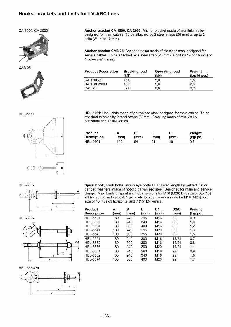
Anchor bracket CA 1500, CA 2000: Anchor bracket made of aluminium alloy designed for main cables. To be attached by 2 steel straps (20 mm) or up to 2 bolts (∅ 14 or 16 mm). Anchor bracket CAB 25: Anchor bracket made of stainless steel designed for service cables. To be attached by a steel strap (20 mm), a bolt (∅ 14 or 16 mm) or 4 screws (∅ 5 mm). Product Description Breaking load Operating load Weight (kN) (kN) (kg/10 pcs) CA 1500-2 15,0 5,0 1,8 CA 1500/2000 19,5 5,0 2,3 CAB 25 2,0 0,8 0,2 HEL 5661: Hook plate made of galvanized steel designed for main cables. To be attached to poles by 2 steel straps (20mm). Breaking loads of min. 28 kN horizontal and 18 kN vertical. Product A B L D Weight Description (mm) (mm) (mm) (mm) (kg/ pc) HEL-5661 150 54 91 16 0,8
HEL-553x
HEL-555x
HEL-556x/7x
Spiral hook, hook bolts, strain eye bolts HEL: Fixed length by welded, flat or bended washers, made of hot-dip galvanized steel. Designed for main and service clamps. Max. loads of spiral and hook versions for M16 (M20) bolt size of 5,5 (13) kN horizontal and vertical. Max. loads for strain eye versions for M16 (M20) bolt size of 40 (40) kN horizontal and 7 (15) kN vertical. Product A B L D1 D2/C Weight Description (mm) (mm) (mm) (mm) (mm) (kg/ pc) HEL-5531 80 240 295 M16 30 0,9 HEL-5532 80 240 340 M16 30 1,0 HEL-5534 80 300 400 M16 30 1,2 HEL-5541 100 240 295 M20 30 1,3 HEL-5543 100 300 355 M20 30 1,5 HEL-5551 80 240 300 M16 17/21 0,7 HEL-5552 80 300 360 M16 17/21 0,8 HEL-5556 80 240 300 M20 17/21 1,1 HEL-5561 80 240 290 M16 22 0,9 HEL-5562 80 240 340 M16 22 1,0 HEL-5574 100 300 400 M20 22 1,7
- 37 -
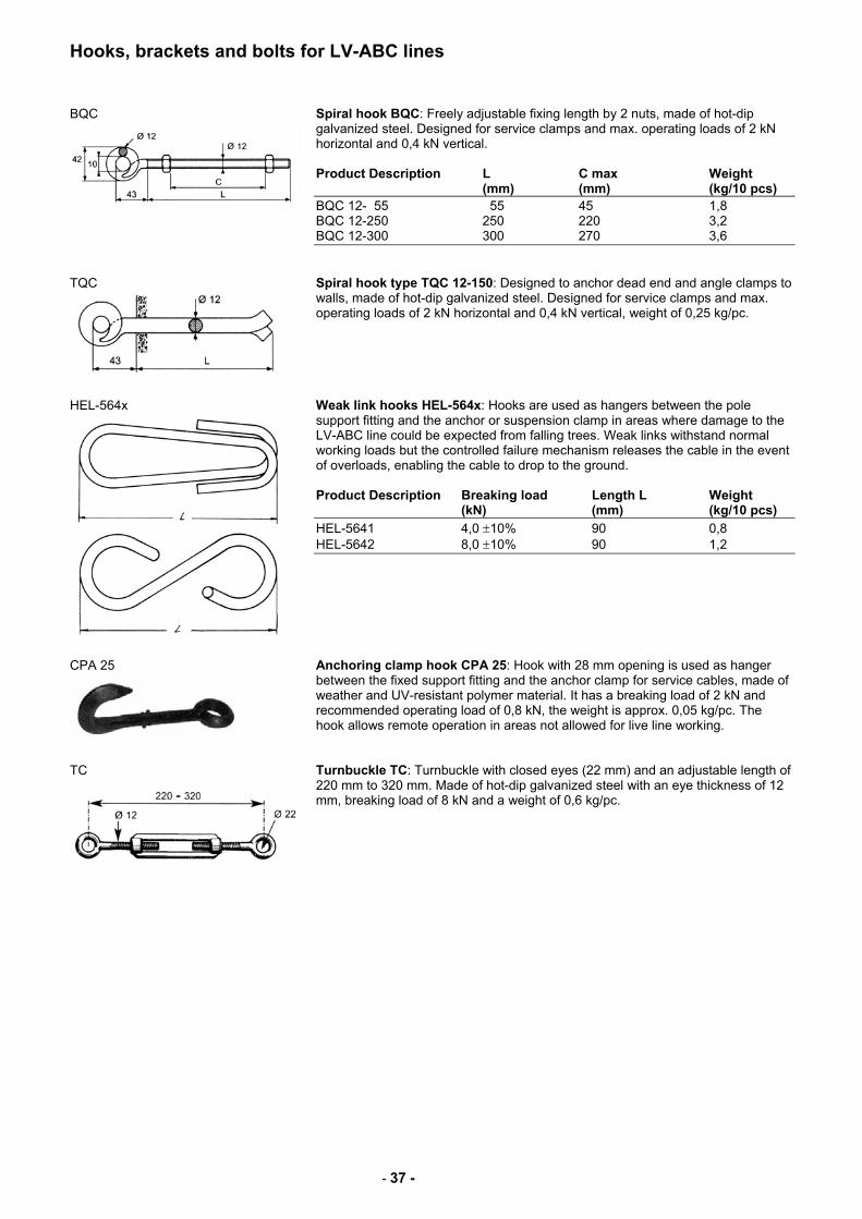
Hooks, brackets and bolts for LV-ABC lines BQC
Spiral hook BQC: Freely adjustable fixing length by 2 nuts, made of hot-dip galvanized steel. Designed for service clamps and max. operating loads of 2 kN horizontal and 0,4 kN vertical. Product Description L C max Weight (mm) (mm) (kg/10 pcs) BQC 12- 55 55 45 1,8 BQC 12-250 250 220 3,2 BQC 12-300 300 270 3,6
TQC
Spiral hook type TQC 12-150: Designed to anchor dead end and angle clamps to walls, made of hot-dip galvanized steel. Designed for service clamps and max. operating loads of 2 kN horizontal and 0,4 kN vertical, weight of 0,25 kg/pc.
HEL-564x
Weak link hooks HEL-564x: Hooks are used as hangers between the pole support fitting and the anchor or suspension clamp in areas where damage to the LV-ABC line could be expected from falling trees. Weak links withstand normal working loads but the controlled failure mechanism releases the cable in the event of overloads, enabling the cable to drop to the ground. Product Description Breaking load Length L Weight (kN) (mm) (kg/10 pcs) HEL-5641 4,0 ±10% 90 0,8 HEL-5642 8,0 ±10% 90 1,2
CPA 25
Anchoring clamp hook CPA 25: Hook with 28 mm opening is used as hanger between the fixed support fitting and the anchor clamp for service cables, made of weather and UV-resistant polymer material. It has a breaking load of 2 kN and recommended operating load of 0,8 kN, the weight is approx. 0,05 kg/pc. The hook allows remote operation in areas not allowed for live line working.
TC
Turnbuckle TC: Turnbuckle with closed eyes (22 mm) and an adjustable length of 220 mm to 320 mm. Made of hot-dip galvanized steel with an eye thickness of 12 mm, breaking load of 8 kN and a weight of 0,6 kg/pc.
- 38 -
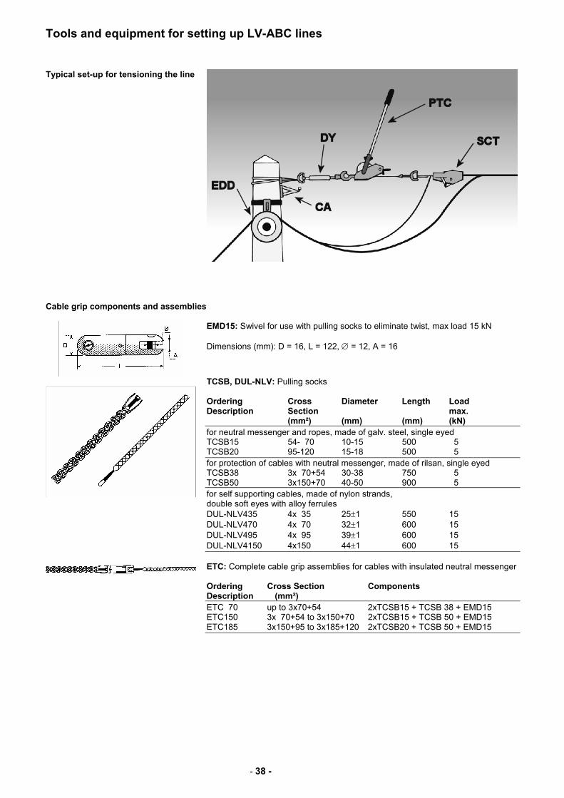
Tools and equipment for setting up LV-ABC lines Typical set-up for tensioning the line
Cable grip components and assemblies
EMD15: Swivel for use with pulling socks to eliminate twist, max load 15 kN Dimensions (mm): D = 16, L = 122, ∅ = 12, A = 16
TCSB, DUL-NLV: Pulling socks Ordering Cross Diameter Length Load Description Section max. (mm²) (mm) (mm) (kN) for neutral messenger and ropes, made of galv. steel, single eyed TCSB15 54- 70 10-15 500 5 TCSB20 95-120 15-18 500 5 for protection of cables with neutral messenger, made of rilsan, single eyed TCSB38 3x 70+54 30-38 750 5 TCSB50 3x150+70 40-50 900 5 for self supporting cables, made of nylon strands, double soft eyes with alloy ferrules DUL-NLV435 4x 35 25±1 550 15 DUL-NLV470 4x 70 32±1 600 15 DUL-NLV495 4x 95 39±1 600 15 DUL-NLV4150 4x150 44±1 600 15
ETC: Complete cable grip assemblies for cables with insulated neutral messenger Ordering Cross Section Components Description (mm²) ETC 70 up to 3x70+54 2xTCSB15 + TCSB 38 + EMD15 ETC150 3x 70+54 to 3x150+70 2xTCSB15 + TCSB 50 + EMD15 ETC185 3x150+95 to 3x185+120 2xTCSB20 + TCSB 50 + EMD15
- 39 -
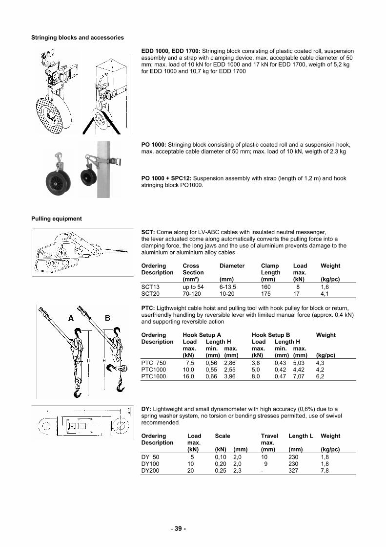
Stringing blocks and accessories
EDD 1000, EDD 1700: Stringing block consisting of plastic coated roll, suspension assembly and a strap with clamping device, max. acceptable cable diameter of 50 mm; max. load of 10 kN for EDD 1000 and 17 kN for EDD 1700, weigth of 5,2 kg for EDD 1000 and 10,7 kg for EDD 1700
PO 1000: Stringing block consisting of plastic coated roll and a suspension hook, max. acceptable cable diameter of 50 mm; max. load of 10 kN, weigth of 2,3 kg PO 1000 + SPC12: Suspension assembly with strap (length of 1,2 m) and hook stringing block PO1000.
Pulling equipment
SCT: Come along for LV-ABC cables with insulated neutral messenger, the lever actuated come along automatically converts the pulling force into a clamping force, the long jaws and the use of aluminium prevents damage to the aluminium or aluminium alloy cables Ordering Cross Diameter Clamp Load Weight Description Section Length max. (mm²) (mm) (mm) (kN) (kg/pc) SCT13 up to 54 6-13,5 160 8 1,6 SCT20 70-120 10-20 175 17 4,1
PTC: Ligthweight cable hoist and pulling tool with hook pulley for block or return, userfriendly handling by reversible lever with limited manual force (approx. 0,4 kN) and supporting reversible action Ordering Hook Setup A Hook Setup B Weight Description Load Length H Load Length H max. min. max. max. min. max. (kN) (mm) (mm) (kN) (mm) (mm) (kg/pc) PTC 750 7,5 0,56 2,86 3,8 0,43 5,03 4,3 PTC1000 10,0 0,55 2,55 5,0 0,42 4,42 4,2 PTC1600 16,0 0,66 3,96 8,0 0,47 7,07 6,2
DY: Lightweight and small dynamometer with high accuracy (0,6%) due to a spring washer system, no torsion or bending stresses permitted, use of swivel recommended Ordering Load Scale Travel Length L Weight Description max. max. (kN) (kN) (mm) (mm) (mm) (kg/pc) DY 50 5 0,10 2,0 10 230 1,8 DY100 10 0,20 2,0 9 230 1,8 DY200 20 0,25 2,3 - 327 7,8
- 40 -
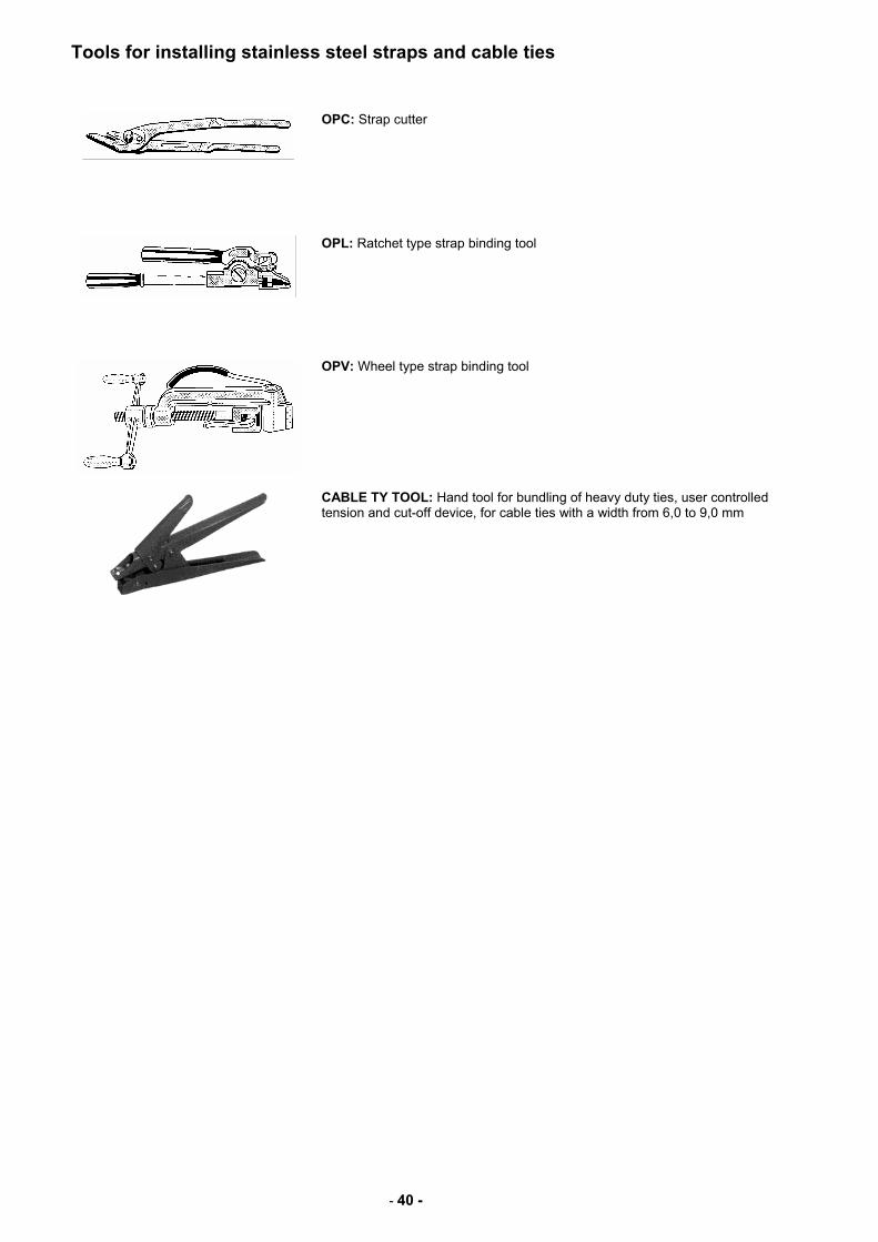
Tools for installing stainless steel straps and cable ties
OPC: Strap cutter
OPL: Ratchet type strap binding tool
OPV: Wheel type strap binding tool
CABLE TY TOOL: Hand tool for bundling of heavy duty ties, user controlled tension and cut-off device, for cable ties with a width from 6,0 to 9,0 mm
- 41 -
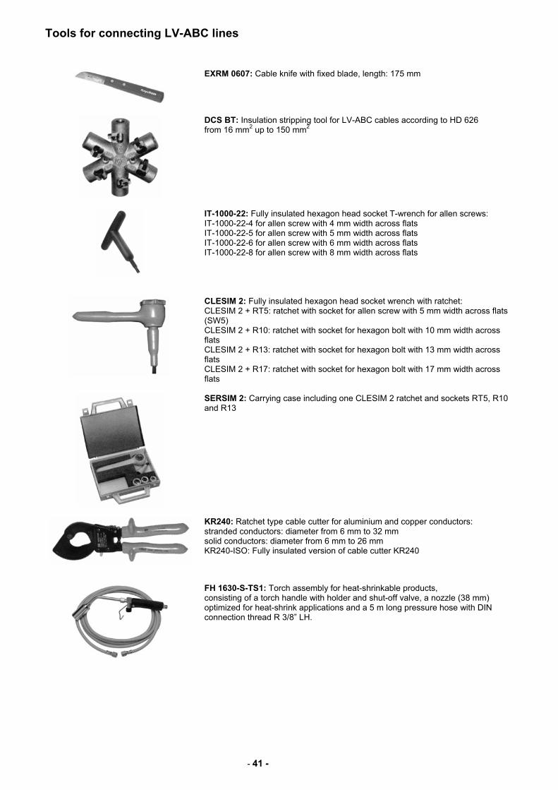
Tools for connecting LV-ABC lines
EXRM 0607: Cable knife with fixed blade, length: 175 mm
DCS BT: Insulation stripping tool for LV-ABC cables according to HD 626 from 16 mm2 up to 150 mm2
IT-1000-22: Fully insulated hexagon head socket T-wrench for allen screws: IT-1000-22-4 for allen screw with 4 mm width across flats IT-1000-22-5 for allen screw with 5 mm width across flats IT-1000-22-6 for allen screw with 6 mm width across flats IT-1000-22-8 for allen screw with 8 mm width across flats
CLESIM 2: Fully insulated hexagon head socket wrench with ratchet: CLESIM 2 + RT5: ratchet with socket for allen screw with 5 mm width across flats (SW5) CLESIM 2 + R10: ratchet with socket for hexagon bolt with 10 mm width across flats CLESIM 2 + R13: ratchet with socket for hexagon bolt with 13 mm width across flats CLESIM 2 + R17: ratchet with socket for hexagon bolt with 17 mm width across flats
SERSIM 2: Carrying case including one CLESIM 2 ratchet and sockets RT5, R10 and R13
KR240: Ratchet type cable cutter for aluminium and copper conductors: stranded conductors: diameter from 6 mm to 32 mm solid conductors: diameter from 6 mm to 26 mm KR240-ISO: Fully insulated version of cable cutter KR240
FH 1630-S-TS1: Torch assembly for heat-shrinkable products, consisting of a torch handle with holder and shut-off valve, a nozzle (38 mm) optimized for heat-shrink applications and a 5 m long pressure hose with DIN connection thread R 3/8” LH.
- 42 -
Compression tools and dies for connecting LV-ABC lines
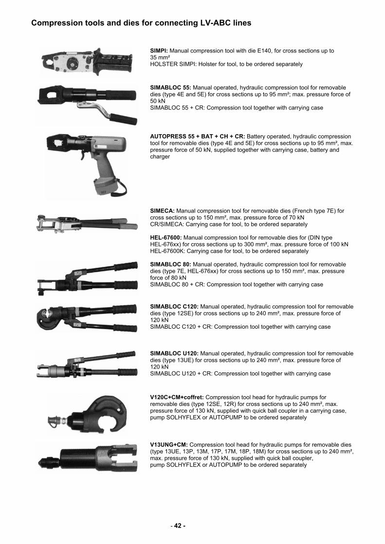
SIMPI: Manual compression tool with die E140, for cross sections up to 35 mm² HOLSTER SIMPI: Holster for tool, to be ordered separately
SIMABLOC 55: Manual operated, hydraulic compression tool for removable dies (type 4E and 5E) for cross sections up to 95 mm²; max. pressure force of 50 kN SIMABLOC 55 + CR: Compression tool together with carrying case
AUTOPRESS 55 + BAT + CH + CR: Battery operated, hydraulic compression tool for removable dies (type 4E and 5E) for cross sections up to 95 mm², max. pressure force of 50 kN, supplied together with carrying case, battery and charger
SIMECA: Manual compression tool for removable dies (French type 7E) for cross sections up to 150 mm², max. pressure force of 70 kN CR/SIMECA: Carrying case for tool, to be ordered separately HEL-67600: Manual compression tool for removable dies for (DIN type HEL-676xx) for cross sections up to 300 mm², max. pressure force of 100 kN HEL-67600K: Carrying case for tool, to be ordered separately
SIMABLOC 80: Manual operated, hydraulic compression tool for removable dies (type 7E, HEL-676xx) for cross sections up to 150 mm², max. pressure force of 80 kN SIMABLOC 80 + CR: Compression tool together with carrying case
SIMABLOC C120: Manual operated, hydraulic compression tool for removable dies (type 12SE) for cross sections up to 240 mm², max. pressure force of 120 kN SIMABLOC C120 + CR: Compression tool together with carrying case
SIMABLOC U120: Manual operated, hydraulic compression tool for removable dies (type 13UE) for cross sections up to 240 mm², max. pressure force of 120 kN SIMABLOC U120 + CR: Compression tool together with carrying case
V120C+CM+coffret: Compression tool head for hydraulic pumps for removable dies (type 12SE, 12R) for cross sections up to 240 mm², max. pressure force of 130 kN, supplied with quick ball coupler in a carrying case, pump SOLHYFLEX or AUTOPUMP to be ordered separately
V13UNG+CM: Compression tool head for hydraulic pumps for removable dies (type 13UE, 13P, 13M, 17P, 17M, 18P, 18M) for cross sections up to 240 mm², max. pressure force of 130 kN, supplied with quick ball coupler, pump SOLHYFLEX or AUTOPUMP to be ordered separately
- 43 -
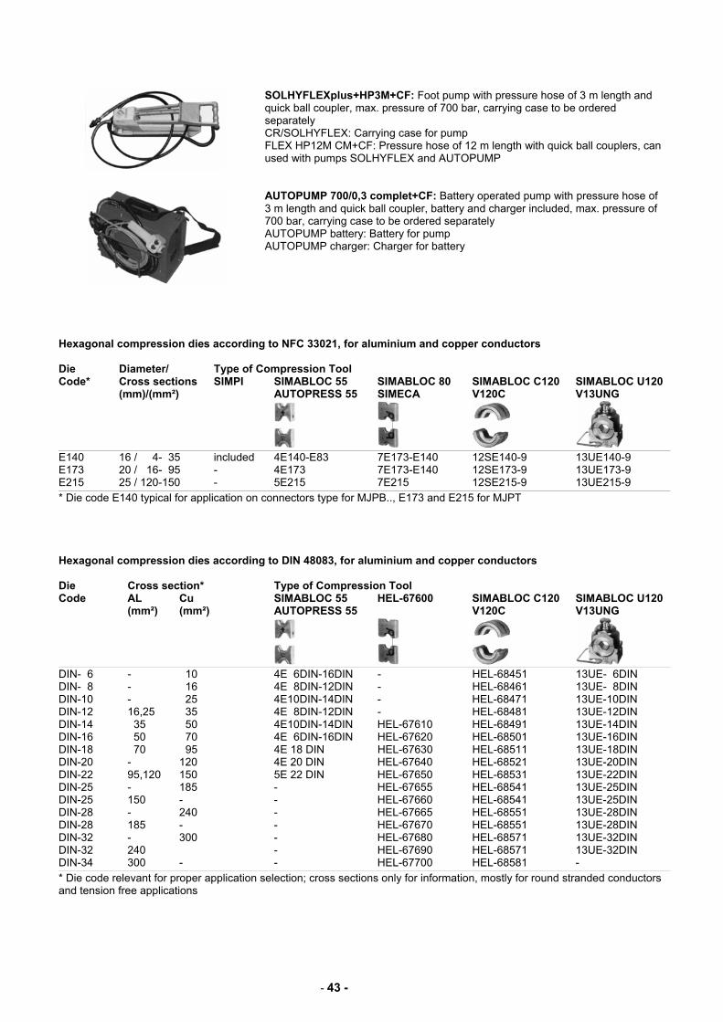
SOLHYFLEXplus+HP3M+CF: Foot pump with pressure hose of 3 m length and quick ball coupler, max. pressure of 700 bar, carrying case to be ordered separately CR/SOLHYFLEX: Carrying case for pump FLEX HP12M CM+CF: Pressure hose of 12 m length with quick ball couplers, can used with pumps SOLHYFLEX and AUTOPUMP
AUTOPUMP 700/0,3 complet+CF: Battery operated pump with pressure hose of 3 m length and quick ball coupler, battery and charger included, max. pressure of 700 bar, carrying case to be ordered separately AUTOPUMP battery: Battery for pump AUTOPUMP charger: Charger for battery
Hexagonal compression dies according to NFC 33021, for aluminium and copper conductors Die Diameter/ Type of Compression Tool Code* Cross sections SIMPI SIMABLOC 55 SIMABLOC 80 SIMABLOC C120 SIMABLOC U120 (mm)/(mm²) AUTOPRESS 55 SIMECA V120C V13UNG
E140 16 / 4- 35 included 4E140-E83 7E173-E140 12SE140-9 13UE140-9 E173 20 / 16- 95 - 4E173 7E173-E140 12SE173-9 13UE173-9 E215 25 / 120-150 - 5E215 7E215 12SE215-9 13UE215-9
* Die code E140 typical for application on connectors type for MJPB.., E173 and E215 for MJPT Hexagonal compression dies according to DIN 48083, for aluminium and copper conductors Die Cross section* Type of Compression Tool Code AL Cu SIMABLOC 55 HEL-67600 SIMABLOC C120 SIMABLOC U120 (mm²) (mm²) AUTOPRESS 55 V120C V13UNG
DIN- 6 - 10 4E 6DIN-16DIN - HEL-68451 13UE- 6DIN DIN- 8 - 16 4E 8DIN-12DIN - HEL-68461 13UE- 8DIN DIN-10 - 25 4E10DIN-14DIN - HEL-68471 13UE-10DIN DIN-12 16,25 35 4E 8DIN-12DIN - HEL-68481 13UE-12DIN DIN-14 35 50 4E10DIN-14DIN HEL-67610 HEL-68491 13UE-14DIN DIN-16 50 70 4E 6DIN-16DIN HEL-67620 HEL-68501 13UE-16DIN DIN-18 70 95 4E 18 DIN HEL-67630 HEL-68511 13UE-18DIN DIN-20 - 120 4E 20 DIN HEL-67640 HEL-68521 13UE-20DIN DIN-22 95,120 150 5E 22 DIN HEL-67650 HEL-68531 13UE-22DIN DIN-25 - 185 - HEL-67655 HEL-68541 13UE-25DIN DIN-25 150 - - HEL-67660 HEL-68541 13UE-25DIN DIN-28 - 240 - HEL-67665 HEL-68551 13UE-28DIN DIN-28 185 - - HEL-67670 HEL-68551 13UE-28DIN DIN-32 - 300 - HEL-67680 HEL-68571 13UE-32DIN DIN-32 240 - HEL-67690 HEL-68571 13UE-32DIN DIN-34 300 - - HEL-67700 HEL-68581 -
* Die code relevant for proper application selection; cross sections only for information, mostly for round stranded conductors and tension free applications
- 44 -
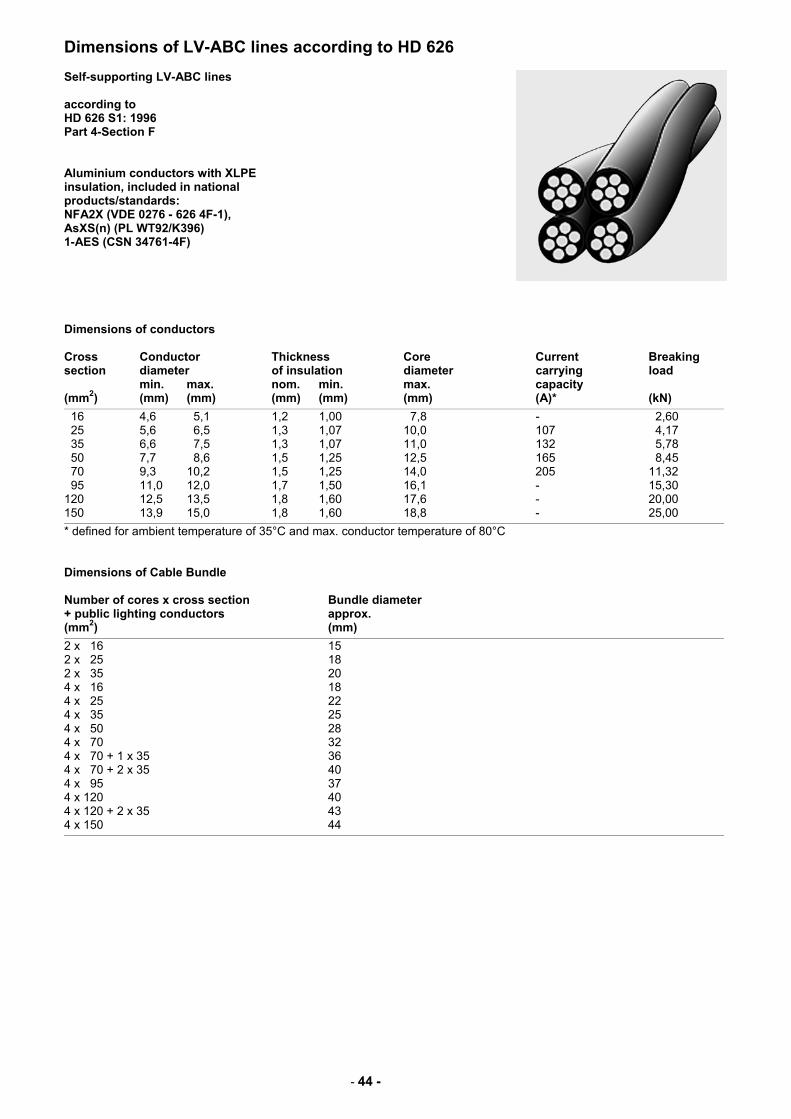
Dimensions of LV-ABC lines according to HD 626 Self-supporting LV-ABC lines according to HD 626 S1: 1996 Part 4-Section F Aluminium conductors with XLPE insulation, included in national products/standards: NFA2X (VDE 0276 - 626 4F-1), AsXS(n) (PL WT92/K396) 1-AES (CSN 34761-4F)
Dimensions of conductors Cross Conductor Thickness Core Current Breaking section diameter of insulation diameter carrying load min. max. nom. min. max. capacity (mm2) (mm) (mm) (mm) (mm) (mm) (A)* (kN)
16 4,6 5,1 1,2 1,00 7,8 - 2,60 25 5,6 6,5 1,3 1,07 10,0 107 4,17 35 6,6 7,5 1,3 1,07 11,0 132 5,78 50 7,7 8,6 1,5 1,25 12,5 165 8,45 70 9,3 10,2 1,5 1,25 14,0 205 11,32 95 11,0 12,0 1,7 1,50 16,1 - 15,30 120 12,5 13,5 1,8 1,60 17,6 - 20,00 150 13,9 15,0 1,8 1,60 18,8 - 25,00
* defined for ambient temperature of 35°C and max. conductor temperature of 80°C Dimensions of Cable Bundle Number of cores x cross section Bundle diameter + public lighting conductors approx. (mm2) (mm)
2 x 16 15 2 x 25 18 2 x 35 20 4 x 16 18 4 x 25 22 4 x 35 25 4 x 50 28 4 x 70 32 4 x 70 + 1 x 35 36 4 x 70 + 2 x 35 40 4 x 95 37 4 x 120 40 4 x 120 + 2 x 35 43 4 x 150 44
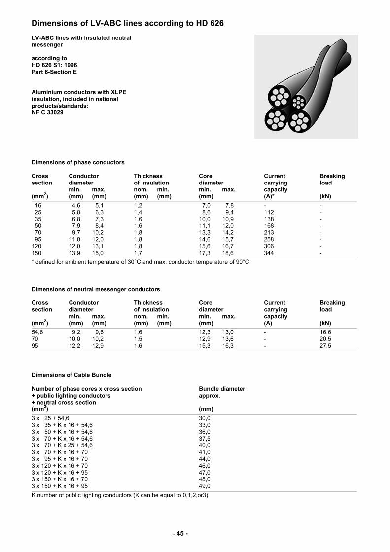
- 45 -
Dimensions of LV-ABC lines according to HD 626 LV-ABC lines with insulated neutral messenger according to HD 626 S1: 1996 Part 6-Section E Aluminium conductors with XLPE insulation, included in national products/standards: NF C 33029
Dimensions of phase conductors Cross Conductor Thickness Core Current Breaking section diameter of insulation diameter carrying load min. max. nom. min. min. max. capacity (mm2) (mm) (mm) (mm) (mm) (mm) (A)* (kN)
16 4,6 5,1 1,2 7,0 7,8 - - 25 5,8 6,3 1,4 8,6 9,4 112 - 35 6,8 7,3 1,6 10,0 10,9 138 - 50 7,9 8,4 1,6 11,1 12,0 168 - 70 9,7 10,2 1,8 13,3 14,2 213 - 95 11,0 12,0 1,8 14,6 15,7 258 - 120 12,0 13,1 1,8 15,6 16,7 306 - 150 13,9 15,0 1,7 17,3 18,6 344 -
* defined for ambient temperature of 30°C and max. conductor temperature of 90°C Dimensions of neutral messenger conductors Cross Conductor Thickness Core Current Breaking section diameter of insulation diameter carrying load min. max. nom. min. min. max. capacity (mm2) (mm) (mm) (mm) (mm) (mm) (A) (kN)
54,6 9,2 9,6 1,6 12,3 13,0 - 16,6 70 10,0 10,2 1,5 12,9 13,6 - 20,5 95 12,2 12,9 1,6 15,3 16,3 - 27,5
Dimensions of Cable Bundle Number of phase cores x cross section Bundle diameter + public lighting conductors approx. + neutral cross section (mm2) (mm)
3 x 25 + 54,6 30,0 3 x 35 + K x 16 + 54,6 33,0 3 x 50 + K x 16 + 54,6 36,0 3 x 70 + K x 16 + 54,6 37,5 3 x 70 + K x 25 + 54,6 40,0 3 x 70 + K x 16 + 70 41,0 3 x 95 + K x 16 + 70 44,0 3 x 120 + K x 16 + 70 46,0 3 x 120 + K x 16 + 95 47,0 3 x 150 + K x 16 + 70 48,0 3 x 150 + K x 16 + 95 49,0
K number of public lighting conductors (K can be equal to 0,1,2,or3)
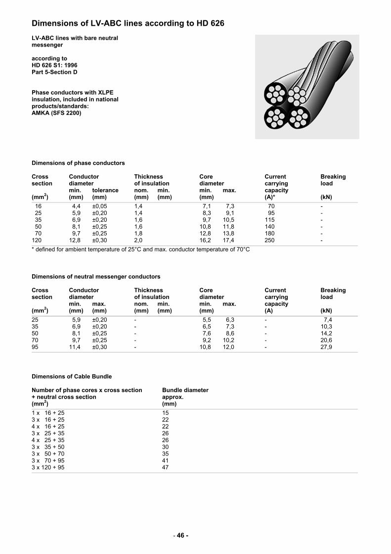
- 46 -
Dimensions of LV-ABC lines according to HD 626 LV-ABC lines with bare neutral messenger according to HD 626 S1: 1996 Part 5-Section D Phase conductors with XLPE insulation, included in national products/standards: AMKA (SFS 2200)
Dimensions of phase conductors Cross Conductor Thickness Core Current Breaking section diameter of insulation diameter carrying load min. tolerance nom. min. min. max. capacity (mm2) (mm) (mm) (mm) (mm) (mm) (A)* (kN)
16 4,4 ±0,05 1,4 7,1 7,3 70 - 25 5,9 ±0,20 1,4 8,3 9,1 95 - 35 6,9 ±0,20 1,6 9,7 10,5 115 - 50 8,1 ±0,25 1,6 10,8 11,8 140 - 70 9,7 ±0,25 1,8 12,8 13,8 180 - 120 12,8 ±0,30 2,0 16,2 17,4 250 -
* defined for ambient temperature of 25°C and max. conductor temperature of 70°C Dimensions of neutral messenger conductors Cross Conductor Thickness Core Current Breaking section diameter of insulation diameter carrying load min. max. nom. min. min. max. capacity (mm2) (mm) (mm) (mm) (mm) (mm) (A) (kN)
25 5,9 ±0,20 - 5,5 6,3 - 7,4 35 6,9 ±0,20 - 6,5 7,3 - 10,3 50 8,1 ±0,25 - 7,6 8,6 - 14,2 70 9,7 ±0,25 - 9,2 10,2 - 20,6 95 11,4 ±0,30 - 10,8 12,0 - 27,9
Dimensions of Cable Bundle Number of phase cores x cross section Bundle diameter + neutral cross section approx. (mm2) (mm)
1 x 16 + 25 15 3 x 16 + 25 22 4 x 16 + 25 22 3 x 25 + 35 26 4 x 25 + 35 26 3 x 35 + 50 30 3 x 50 + 70 35 3 x 70 + 95 41 3 x 120 + 95 47
All of the above information, including drawings, illustrations and graphic designs, reflects our present understanding and is to the best of our knowledge and belief correct and reliable. Users, however, should independently evaluate the suitability of each product for the desired application. Under no circumstances does this constitute an assurance of any particular quality or performance. Such an assurance is only provided in the context of our product specifications or explicit contractual arrangements. Our liability for these products is set forth in our standard terms and conditions of sale. GURO, Hellstern, Raychem, and SIMEL are trademarks.
Tyco Electronics Raychem GmbH Energy Division CEE/CIS Finsinger Feld 1 Ottobrunn/Munich Germany Tel. +49 / 89-6089-485 Fax +49 / 89-6089-484 EN-CEE/[email protected]
©Ty
co E
lect
roni
cs E
PP
087
4 C
EE
02/
05