Embed Size (px)
Citation preview

USER INSTRUCTIONS
CPXS, CPXNS and CPXPS
Frame mounted, modular design, centrifugal, chemical process pumps with magnetic drive
PCN=71569250 09-08 (E) (Based on C957KH025 and C957KH049.) Original instructions.
InstallationOperation
Maintenance
These instructions must be read prior to installing, operating, using and maintaining this equipment.
CPXS, CPXNS and CPXPS USER INSTRUCTIONS ENGLISH 71569250 09-08
Page 2 of 40 flowserve.com
CONTENTS Page
1 INTRODUCTION AND SAFETY............................ 2 1.1 General ........................................................... 2 1.2 CE marking and approvals.............................. 2 1.3 Disclaimer ....................................................... 2 1.4 Copyright......................................................... 2 1.5 Duty conditions................................................ 2 1.6 Safety .............................................................. 2 1.7 Nameplate and safety labels........................... 2 1.8 Specific machine performance........................ 2 1.9 Noise level....................................................... 2
2 TRANSPORT AND STORAGE.............................. 2 2.1 Consignment receipt and unpacking............... 2 2.2 Handling .......................................................... 2 2.3 Lifting............................................................... 2 2.4 Storage............................................................ 2 2.5 Recycling and end of product life.................... 2
3 DESCRIPTION ...................................................... 2 3.1 Configurations................................................. 2 3.2 Name nomenclature........................................ 2 3.3 Design of major parts ...................................... 2 3.4 Performance and operating limits ................... 2
4 INSTALLATION...................................................... 2 4.1 Location........................................................... 2 4.2 Part assemblies............................................... 2 4.3 Foundation ...................................................... 2 4.4 Grouting .......................................................... 2 4.5 Initial alignment ............................................... 2 4.6 Piping .............................................................. 2 4.7 Final shaft alignment check ............................ 2 4.8 Electrical connections ..................................... 2 4.9 Protection systems.......................................... 2
5 COMMISSIONING, START-UP, OPERATION AND SHUTDOWN ............................................. 2
5.1 Pre-commissioning procedure ........................ 2 5.2 Pump lubricants .............................................. 2 5.3 Open impeller clearance ................................. 2 5.4 Direction of rotation......................................... 2 5.5 Guarding ......................................................... 2 5.6 Priming and auxiliary supplies ........................ 2 5.7 Starting the pump............................................ 2 5.8 Running the pump........................................... 2 5.9 Stopping and shutdown................................... 2 5.10 Hydraulic, mechanical and electrical duty..... 2
Page
6 MAINTENANCE .....................................................2 6.1 General ............................................................2 6.2 Maintenance schedule.....................................2 6.3 Spare parts ......................................................2 6.4 Recommended spares ....................................2 6.5 Tools required ..................................................2 6.6 Fastener torques..............................................2 6.7 Setting impeller clearance ...............................2 6.8 Disassembly ....................................................2 6.9 Examination of parts ........................................2 6.10 Magnets .........................................................2 6.11 Assembly........................................................2
7 FAULTS; CAUSES AND REMEDIES.....................2 8 PARTS LISTS AND DRAWINGS ...........................2
8.1 CPXS – frame mounted – coated shaft – PEEK shell..................................................2
8.2 CPXS – frame mounted – sleeved shaft – PEEK shell..................................................2
8.3 CPXS – frame mounted – coated shaft – dual containment ........................................2
8.4 CPXS – frame mounted – sleeved shaft – dual containment ........................................2
8.5 CPXS – frame mounted – coated shaft – metal shell ..................................................2
8.6 CPXS – frame mounted – sleeved shaft – metal shell ..................................................2
8.7 CPXPS – frame mounted – coated shaft – PEEK shell..................................................2
8.8 CPXPS – frame mounted – sleeved shaft – PEEK shell..................................................2
8.9 CPXPS - auxiliary connection points ...............2 8.10 CPXS - parts interchangeability.....................2 8.11 General arrangement drawing .......................2
9 CERTIFICATION ....................................................2 10 OTHER RELEVANT DOCUMENTATION AND
MANUALS ..........................................................2 10.1 Supplementary User Instruction manuals .....2 10.2 Change notes ................................................2 10.3 Additional sources of information...................2

CPXS, CPXNS and CPXPS USER INSTRUCTIONS ENGLISH 71569250 09-08
Page 3 of 40 flowserve.com
INDEX Page
Additional sources (10.3)......................................... 39 Alignment of shafting (4.3, 4.5 and 4.7) Assembly (6.11)....................................................... 25 ATEX marking (1.6.4.2) ............................................. 7 Bearing sizes and capacities (5.2.2)........................ 16 CE marking and approvals (1.2)................................ 4 Certification (9) ........................................................ 39 Change notes (10.2) ................................................ 39 Clearances, impeller (6.7) ....................................... 22 Commissioning and operation (5)............................ 15 Compliance, ATEX (1.6.4.1)...................................... 6 Configurations (3.1) ................................................. 10 Copyright (1.4) ........................................................... 4 Design of major parts (3.3) ...................................... 11 Direction of rotation (5.4) ......................................... 17 Disassembly (6.8) .................................................... 22 Disclaimer (1.3).......................................................... 4 Dismantling (6.8, Disassembly) ............................... 22 Drawings (8) ............................................................ 29 Duty conditions (1.5).................................................. 4 Electrical connections (4.8) ..................................... 14 End of product life (2.5) ........................................... 10 Examination of parts (6.9) ....................................... 24 Fastener torques (6.6) ............................................. 22 Faults; causes and remedies (7) ............................. 27 Foundation (4.3) ...................................................... 11 General arrangement drawing (8.11) ...................... 39 General assembly drawings (8)............................... 29 Grouting (4.4)........................................................... 12 Guarding (5.5).......................................................... 17 Handling (2.2) .......................................................... 10 Hydraulic, mechanical and electrical duty (5.10)..... 19 Impeller clearance (5.3 and 6.7) Inspection (6.2.1 and 6.2.2)..................................... 20 Installation (4) .......................................................... 11 Lifting (2.3)............................................................... 10 Location (4.1)........................................................... 11 Lubrication (5.1.1, 5.2 and 6.2.3) Lubrication schedule (5.2.3) .................................... 17 Magnets (6.10)......................................................... 24 Maintenance (6)....................................................... 20 Maintenance schedule (6.2) .................................... 19 Name nomenclature (3.2)........................................ 10 Nameplate (1.7.1) ...................................................... 8 Operating limits (3.4.1) ............................................ 11 Ordering spare parts (6.3.1) .................................... 21
Page
Part assemblies (4.2) ...............................................11 Parts lists (8) ............................................................29 Performance (3.4) ....................................................11 Piping (4.6) ...............................................................13 Pre-commissioning (5.1) ..........................................15 Priming and auxiliary supplies (5.6) .........................17 Protection systems (4.9) ..........................................15 Reassembly (6.11, Assembly) .................................25 Receipt and unpacking (2.1) ....................................10 Recommended fill quantities (see 5.2.2)..................16 Recommended oil lubricants (5.2.1) ........................16 Recommended spares (6.4).....................................21 Recycling (2.5) .........................................................10 Replacement parts (6.3 and 6.4)..............................21 Running the pump (5.8) ...........................................18 Safety action (1.6.3) ...................................................5 Safety markings (1.6.1) ..............................................5 Safety, protection systems (1.6 and 4.9) Sectional drawings (8)..............................................29 Setting impeller clearance (6.7) ...............................22 Sound pressure level (1.9, Noise level) .....................9 Sources, additional information (10.3) .....................39 Spare parts (6.3) ......................................................21 Specific machine performance (1.8) ..........................9 Starting the pump (5.7) ............................................18 Stop/start frequency (5.8.3)......................................18 Stopping and shutdown (5.9) ...................................19 Storage, pump (2.4) .................................................10 Storage, spare parts (6.3.2) .....................................21 Supplementary manuals or information sources......39 Supplementary User Instructions (10.1)...................39 Thermal expansion (4.5.1) .......................................12 Tools required (6.5) ..................................................21 Torques for fasteners (6.6).......................................22 Trouble-shooting (see 7) ..........................................27 Vibration (5.8.2)........................................................18 Warning labels (1.7.2) ................................................8
CPXS, CPXNS and CPXPS USER INSTRUCTIONS ENGLISH 71569250 09-08
Page 4 of 40 flowserve.com
1 INTRODUCTION AND SAFETY 1.1 General
These instructions must always be kept close to the product's operating location or directly with the product. Flowserve products are designed, developed and manufactured with state-of-the-art technologies in modern facilities. The unit is produced with great care and commitment to continuous quality control, utilising sophisticated quality techniques and safety requirements. Flowserve is committed to continuous quality improvement and being at service for any further information about the product in its installation and operation or about its support products, repair and diagnostic services. These instructions are intended to facilitate familiarization with the product and its permitted use. Operating the product in compliance with these instructions is important to help ensure reliability in service and avoid risks. The instructions may not take into account local regulations; ensure such regulations are observed by all, including those installing the product. Always coordinate repair activity with operations personnel, and follow all plant safety requirements and applicable safety and health laws/regulations.
These instructions should be read prior to installing, operating, using and maintaining the equipment in any region worldwide. The equipment must not be put into service until all the conditions relating to safety noted in the instructions, have been met. 1.2 CE marking and approvals It is a legal requirement that machinery and equipment put into service within certain regions of the world shall conform with the applicable CE Marking Directives covering Machinery and, where applicable, Low Voltage Equipment, Electromagnetic Compatibility (EMC), Pressure Equipment Directive (PED) and Equipment for Potentially Explosive Atmospheres (ATEX). Where applicable, the Directives and any additional Approvals, cover important safety aspects relating to machinery and equipment and the satisfactory provision of technical documents and safety instructions. Where applicable this document incorporates information relevant to these Directives and Approvals.
To confirm the Approvals applying and if the product is CE marked, check the serial number plate markings and the Certification. (See section 9, Certification.) 1.3 Disclaimer Information in these User Instructions is believed to be reliable. In spite of all the efforts of Flowserve Corporation to provide sound and all necessary information the content of this manual may appear insufficient and is not guaranteed by Flowserve as to its completeness or accuracy. Flowserve manufactures products to exacting International Quality Management System Standards as certified and audited by external Quality Assurance organisations. Genuine parts and accessories have been designed, tested and incorporated into the products to help ensure their continued product quality and performance in use. As Flowserve cannot test parts and accessories sourced from other vendors the incorrect incorporation of such parts and accessories may adversely affect the performance and safety features of the products. The failure to properly select, install or use authorised Flowserve parts and accessories is considered to be misuse. Damage or failure caused by misuse is not covered by the Flowserve warranty. In addition, any modification of Flowserve products or removal of original components may impair the safety of these products in their use. 1.4 Copyright All rights reserved. No part of these instructions may be reproduced, stored in a retrieval system or transmitted in any form or by any means without prior permission of Flowserve Pump Division. 1.5 Duty conditions This product has been selected to meet the specifications of your purchaser order. The acknowledgement of these conditions has been sent separately to the Purchaser. A copy should be kept with these instructions.
The product must not be operated beyond the parameters specified for the application. If there is any doubt as to the suitability of the product for the application intended, contact Flowserve for advice, quoting the serial number. If the conditions of service on your purchase order are going to be changed (for example liquid pumped, temperature or duty) it is requested that the user seeks the written agreement of Flowserve before start up.

CPXS, CPXNS and CPXPS USER INSTRUCTIONS ENGLISH 71569250 09-08
Page 5 of 40 flowserve.com
1.6 Safety 1.6.1 Summary of safety markings These User Instructions contain specific safety markings where non-observance of an instruction would cause hazards. The specific safety markings are:
This symbol indicates electrical safety instructions where non-compliance will involve a high risk to personal safety or the loss of life.
This symbol indicates safety instructions where non-compliance would affect personal safety and could result in loss of life.
This symbol indicates “hazardous and toxic fluid” safety instructions where non-compliance would affect personal safety and could result in loss of life.
This symbol indicates safety instructions where non-compliance will involve some risk to safe operation and personal safety and would damage the equipment or property.
This symbol indicates “strong magnetic field” safety instructions where non-compliance would affect personal safety, pacemakers, instruments, or stored data sensitive to magnetic fields.
This symbol indicates explosive atmosphere zone marking according to ATEX. It is used in safety instructions where non-compliance in the hazardous area would cause the risk of an explosion.
This symbol is used in safety instructions to remind not to rub non-metallic surfaces with a dry cloth; ensure the cloth is damp. It is used in safety instructions where non-compliance in the hazardous area would cause the risk of an explosion.
This sign is not a safety symbol but indicates an important instruction in the assembly process. 1.6.2 Personnel qualification and training All personnel involved in the operation, installation, inspection and maintenance of the unit must be qualified to carry out the work involved. If the personnel in question do not already possess the necessary knowledge and skill, appropriate training and instruction must be provided. If required the operator may commission the manufacturer/supplier to provide applicable training. Always coordinate repair activity with operations and health and safety personnel, and follow all plant safety requirements and applicable safety and health laws and regulations.
1.6.3 Safety action This is a summary of conditions and actions to help prevent injury to personnel and damage to the environment and to equipment. For products used in potentially explosive atmospheres section 1.6.4 also applies.
NEVER DO MAINTENANCE WORK WHEN THE UNIT IS CONNECTED TO POWER
GUARDS MUST NOT BE REMOVED WHILE THE PUMP IS OPERATIONAL
DRAIN THE PUMP AND ISOLATE PIPEWORK BEFORE DISMANTLING THE PUMP The appropriate safety precautions should be taken where the pumped liquids are hazardous.
FLUORO-ELASTOMERS (When fitted.) When a pump has experienced temperatures over 250 ºC (482 ºF), partial decomposition of fluoro-elastomers (example: Viton) will occur. In this condition these are extremely dangerous and skin contact must be avoided.
HANDLING COMPONENTS Many precision parts have sharp corners and the wearing of appropriate safety gloves and equipment is required when handling these components. To lift heavy pieces above 25 kg (55 lb) use a crane appropriate for the mass and in accordance with current local regulations.
THERMAL SHOCK Rapid changes in the temperature of the liquid within the pump can cause thermal shock, which can result in damage or breakage of components and should be avoided.
NEVER APPLY HEAT TO REMOVE IMPELLER Trapped lubricant or vapour could cause an explosion.
HOT (and cold) PARTS If hot or freezing components or auxiliary heating supplies can present a danger to operators and persons entering the immediate area action must be taken to avoid accidental contact. If complete protection is not possible, the machine access must be limited to maintenance staff only, with clear visual warnings and indicators to those entering the immediate area. Note: bearing housings must not be insulated and drive motors and bearings may be hot. If the temperature is greater than 80 ºC (175 ºF) or below -5 ºC (20 ºF) in a restricted zone, or exceeds local regulations, action as above shall be taken.
CPXS, CPXNS and CPXPS USER INSTRUCTIONS ENGLISH 71569250 09-08
Page 6 of 40 flowserve.com
HAZARDOUS LIQUIDS When the pump is handling hazardous liquids care must be taken to avoid exposure to the liquid by appropriate siting of the pump, limiting personnel access and by operator training. If the liquid is flammable and or explosive, strict safety procedures must be applied. Gland packing must not be used when pumping hazardous liquids.
PREVENT EXCESSIVE EXTERNAL PIPE LOAD Do not use pump as a support for piping. Do not mount expansion joints, unless allowed by Flowserve in writing, so that their force, due to internal pressure, acts on the pump flange.
NEVER RUN THE PUMP DRY
ENSURE CORRECT LUBRICATION (See section 5, Commissioning, startup, operation and shutdown.)
ONLY CHECK DIRECTION OF MOTOR ROTATION WITH COUPLING ELEMENT/ PINS REMOVED Starting in reverse direction of rotation will damage the pump.
START THE PUMP WITH OUTLET VALVE PART OPENED (Unless otherwise instructed at a specific point in the User Instructions.) This is recommended to minimize the risk of overloading and damaging the pump or motor at full or zero flow. Pumps may be started with the valve further open only on installations where this situation cannot occur. The pump outlet control valve may need to be adjusted to comply with the duty following the run-up process. (See section 5, Commissioning start-up, operation and shutdown.)
INLET VALVES TO BE FULLY OPEN WHEN PUMP IS RUNNING Running the pump at zero flow or below the recommended minimum flow continuously will cause damage to the pump and mechanical seal.
DO NOT RUN THE PUMP AT ABNORMALLY HIGH OR LOW FLOW RATES Operating at a flow rate higher than normal or at a flow rate with no back pressure on the pump may overload the motor and cause cavitation. Low flow rates may cause a reduction in pump/bearing life, overheating of the pump, instability and cavitation/vibration.
HIGH MAGNETIC FIELDS Great care should be taken when assembling/ dismantling magnetic rotors, where fitted, because of the very high forces which can be created by the magnets. Persons with pacemakers and any instrumentation etc sensitive to magnetic fields should be kept well away from the magnetic drive unit during dismantling. 1.6.4 Products used in potentially explosive atmospheres
Measures are required to: • Avoid excess temperature • Prevent build up of explosive mixtures • Prevent the generation of sparks • Prevent leakages • Maintain the pump to avoid hazard The following instructions for pumps and pump units when installed in potentially explosive atmospheres must be followed to help ensure explosion protection. Both electrical and non-electrical equipment must meet the requirements of European Directive 94/9/EC. 1.6.4.1 Scope of compliance
Use equipment only in the zone for which it is appropriate. Always check that the driver, drive coupling assembly, seal and pump equipment are suitably rated and/or certified for the classification of the specific atmosphere in which they are to be installed. Where Flowserve has supplied only the bare shaft pump, the Ex rating applies only to the pump. The party responsible for assembling the pump set shall select the coupling, driver and any additional equipment, with the necessary CE Certificate/ Declaration of Conformity establishing it is suitable for the area in which it is to be installed. The output from a variable frequency drive (VFD) can cause additional heating effects in the motor and so, for pumps sets with a VFD, the ATEX Certification for the motor must state that it is covers the situation where electrical supply is from the VFD. This particular requirement still applies even if the VFD is in a safe area.

CPXS, CPXNS and CPXPS USER INSTRUCTIONS ENGLISH 71569250 09-08
Page 7 of 40 flowserve.com
1.6.4.2 Marking An example of ATEX equipment marking is shown below. The actual classification of the pump will be engraved on the nameplate.
II 2 GD c IIC 135 ºC (T4)
Equipment Group I = Mining II = Non-mining
Category 2 or M2 = high level protection 3 = normal level of protection
Gas and/or dust G = Gas D = Dust
c = Constructional safety (in accordance with EN13463-5)
Gas Group (Equipment Category 2 only) IIA – Propane (typical) IIB – Ethylene (typical) IIC – Hydrogen (typical)
Maximum surface temperature (Temperature Class) (see section 1.6.4.3.) 1.6.4.3 Avoiding excessive surface temperatures
ENSURE THE EQUIPMENT TEMPERATURE CLASS IS SUITABLE FOR THE HAZARD ZONE Pumps have a temperature class as stated in the ATEX Ex rating on the nameplate. These are based on a maximum ambient of 40 ºC (104 ºF); refer to Flowserve for higher ambient temperatures. The surface temperature on the pump is influenced by the temperature of the liquid handled. The maximum permissible liquid temperature depends on the temperature class and must not exceed the values in the table that follows. The temperature rise at the seals and bearings and due to the minimum permitted flow rate is taken into account in the temperatures stated.
Temperature class to
EN13463-1
Maximum surface
temperature permitted
Temperature limit of liquid handled (* depending on material and construction
variant - check which is lower) T6 T5 T4 T3 T2 T1
85 °C (185 °F) 100 °C (212 °F) 135 °C (275 °F) 200 °C (392 °F) 300 °C (572 °F) 450 °C (842 °F)
Consult Flowserve Consult Flowserve 115 °C (239 °F) * 180 °C (356 °F) * 275 °C (527 °F) * 400 °C (752 °F) *
The responsibility for compliance with the specified maximum liquid temperature is with the plant operator. Temperature classification “Tx” is used when the liquid temperature varies and when the pump is required to be used in differently classified potentially explosive atmospheres. In this case the user is responsible for ensuring that the pump surface temperature does not exceed that permitted in its actual installed location. Do not attempt to check the direction of rotation with the coupling element/pins fitted due to the risk of severe contact between rotating and stationary components. Where there is any risk of the pump being run against a closed valve generating high liquid and casing external surface temperatures it is recommended that users fit an external surface temperature protection device. Avoid mechanical, hydraulic or electrical overload by using motor overload trips, temperature monitor or a power monitor and make routine vibration monitoring checks. In dirty or dusty environments, regular checks must be made and dirt removed from areas around close clearances, bearing housings and motors. Additional requirements for CPXPS pumps only Where the system operation does not ensure control of priming, as defined in these User Instructions, and the maximum permitted surface temperature of the T Class could be exceeded, it is recommended that users fit an external surface temperature protection device. 1.6.4.4 Preventing the build up of explosive mixtures
ENSURE THE PUMP IS PROPERLY FILLED AND VENTED AND DOES NOT RUN DRY Ensure the pump and relevant suction and discharge pipeline system is totally filled with liquid at all times during the pump operation, so that an explosive atmosphere is prevented. In addition it is essential to make sure that seal chambers, auxiliary shaft seal systems and any heating and cooling systems are properly filled. If the operation of the system cannot avoid this condition the fitting of an appropriate dry run protection device is recommended (for example liquid detection or a power monitor).

CPXS, CPXNS and CPXPS USER INSTRUCTIONS ENGLISH 71569250 09-08
Page 8 of 40 flowserve.com
To avoid potential hazards from fugitive emissions of vapour or gas to atmosphere the surrounding area must be well ventilated. 1.6.4.5 Preventing sparks
To prevent a potential hazard from mechanical contact, the coupling guard must be non-sparking. To avoid the potential hazard from random induced current generating a spark, the earth contact on the baseplate must be used.
Avoid electrostatic charge: do not rub non-metallic surfaces with a dry cloth; ensure cloth is damp. The coupling must be selected to comply with 94/9/EC and correct alignment must be maintained. Additional requirement for metallic pumps on non-metallic baseplates When metallic components are fitted on a non-metallic baseplate they must be individually earthed. 1.6.4.6 Preventing leakage
The pump must only be used to handle liquids for which it has been approved to have the correct corrosion resistance. Avoid entrapment of liquid in the pump and associated piping due to closing of suction and discharge valves, which could cause dangerous excessive pressures to occur if there is heat input to the liquid. This can occur if the pump is stationary or running. Bursting of liquid containing parts due to freezing must be avoided by draining or protecting the pump and ancillary systems. Where there is the potential hazard of a loss of a seal barrier fluid or external flush, the fluid must be monitored. If leakage of liquid to atmosphere can result in a hazard, the installation of a liquid detection device is recommended. 1.6.4.7 Maintenance to avoid the hazard
CORRECT MAINTENANCE IS REQUIRED TO AVOID POTENTIAL HAZARDS WHICH GIVE A RISK OF EXPLOSION The responsibility for compliance with maintenance instructions is with the plant operator.
To avoid potential explosion hazards during maintenance, the tools, cleaning and painting materials used must not give rise to sparking or adversely affect the ambient conditions. Where there is a risk from such tools or materials, maintenance must be conducted in a safe area. It is recommended that a maintenance plan and schedule is adopted. (See section 6, Maintenance.) 1.7 Nameplate and safety labels 1.7.1 Nameplate For details of nameplate, see the Declaration of Conformity, or separate documentation included with these User Instructions. 1.7.2 Safety labels
Oil lubricated units only:

CPXS, CPXNS and CPXPS USER INSTRUCTIONS ENGLISH 71569250 09-08
Page 9 of 40 flowserve.com
1.8 Specific machine performance For performance parameters see section 1.5, Duty conditions. Where performance data has been supplied separately to the purchaser these should be obtained and retained with these User Instructions if required. 1.9 Noise level Attention must be given to the exposure of personnel to the noise, and local legislation will define when guidance to personnel on noise limitation is required, and when noise exposure reduction is mandatory. This is typically 80 to 85 dBA. The usual approach is to control the exposure time to the noise or to enclose the machine to reduce emitted sound. You may have already specified a limiting noise level when the equipment was ordered, however if no noise requirements were defined, then attention is drawn to the following table to give an indication of equipment noise level so that you can take the appropriate action in your plant. Pump noise level is dependent on a number of operational factors, flow rate, pipework design and acoustic characteristics of the building, and so the
values given are subject to a 3 dBA tolerance and cannot be guaranteed. Similarly the motor noise assumed in the “pump and motor” noise is that typically expected from standard and high efficiency motors when on load directly driving the pump. Note that a motor driven by an inverter may show an increased noise at some speeds. If a pump unit only has been purchased for fitting with your own driver then the “pump only” noise levels in the table should be combined with the level for the driver obtained from the supplier. Consult Flowserve or a noise specialist if assistance is required in combining the values. It is recommended that where exposure approaches the prescribed limit, then site noise measurements should be made. The values are in sound pressure level LpA at 1 m (3.3 ft) from the machine, for “free field conditions over a reflecting plane”. For estimating sound power level LWA (re 1 pW) then add 14 dBA to the sound pressure value.
Typical sound pressure level LpA at 1 m reference 20 µPa, dBA
3 550 r/min 2 900 r/min 1 750 r/min 1 450 r/min Motor size and speed
kW (hp) Pump only
Pump andmotor
Pump only
Pump and motor
Pump only
Pump and motor
Pump only
Pump and motor
<0.55(<0.75) 72 72 64 65 62 64 62 64 0.75 (1) 72 72 64 66 62 64 62 64 1.1 (1.5) 74 74 66 67 64 64 62 63 1.5 (2) 74 74 66 71 64 64 62 63 2.2 (3) 75 76 68 72 65 66 63 64 3 (4) 75 76 70 73 65 66 63 64 4 (5) 75 76 71 73 65 66 63 64
5.5 (7.5) 76 77 72 75 66 67 64 65 7.5 (10) 76 77 72 75 66 67 64 65 11(15) 80 81 76 78 70 71 68 69 15 (20) 80 81 76 78 70 71 68 69
18.5 (25) 81 81 77 78 71 71 69 71 22 (30) 81 81 77 79 71 71 69 71 30 (40) 83 83 79 81 73 73 71 73 37 (50) 83 83 79 81 73 73 71 73 45 (60) 86 86 82 84 76 76 74 76 55 (75) 86 86 82 84 76 76 74 76
75 (100) 87 87 83 85 77 77 75 77 90 (120) 87 88 83 85 77 78 75 78 110 (150) 89 90 85 87 79 80 77 80 150 (200) 89 90 85 87 79 80 77 80
Note: for 1 180 and 960 r/min reduce 1 450 r/min values by 2 dBA. For 880 and 720 r/min reduce 1 450 r/min values by 3 dBA.

CPXS, CPXNS and CPXPS USER INSTRUCTIONS ENGLISH 71569250 09-08
Page 10 of 40 flowserve.com
2 TRANSPORT AND STORAGE 2.1 Consignment receipt and unpacking Immediately after receipt of the equipment it must be checked against the delivery/shipping documents for its completeness and that there has been no damage in transportation. Any shortage and/or damage must be reported immediately to Flowserve Pump Division and must be received in writing within one month of receipt of the equipment. Later claims cannot be accepted. Check any crate, boxes or wrappings for any accessories or spare parts that may be packed separately with the equipment or attached to side walls of the box or equipment. Each product has a unique serial number. Check that this number corresponds with that advised and always quote this number in correspondence as well as when ordering spare parts or further accessories. 2.2 Handling Boxes, crates, pallets or cartons may be unloaded using fork lift vehicles or slings dependent on their size and construction. 2.3 Lifting
A crane must be used for all pump sets in excess of 25 kg (55 lb). Fully trained personnel must carry out lifting, in accordance with local regulations. The pump and cast iron baseplate set should be lifted as shown:
Where the baseplate is folded steel there are no specific lifting points provided for this complete machine set (unless so identified). Any lifting points that can be seen are provided only for dismantling parts for servicing. Slings, ropes and other lifting gear should be positioned where they cannot slip and where a balanced lift is obtained. Before lifting the driver alone, refer to the manufacturer’s instructions.
2.4 Storage
Store the pump in a clean, dry location away from vibration. Leave piping connection covers in place to keep dirt and other foreign material out of pump casing. Turn pump at intervals to prevent brinelling of the bearings and the seal faces, if fitted, from sticking. The pump may be stored as above for up to 6 months. Consult Flowserve for preservative actions when a longer storage period is needed. 2.5 Recycling and end of product life At the end of the service life of the product or its parts, the relevant materials and parts should be recycled or disposed of using an environmentally acceptable method and local requirements. If the product contains substances that are harmful to the environment, these should be removed and disposed of in accordance with current regulations. This also includes the liquids and/or gases that may be used in the "seal system" or other utilities.
Make sure that hazardous substances are disposed of safely and that the correct personal protective equipment is used. The safety specifications must be in accordance with the current regulations at all times. 3 DESCRIPTION 3.1 Configurations The pump is a modular designed centrifugal pump that can be built to achieve almost all chemical liquid pumping requirements. For ultimate safety the pump has been fitted with a magnetic drive. (See 3.2 and 3.3 below.) 3.2 Name nomenclature The pump size will be engraved on the nameplate typically as below: 80-50CPXS200 Nominal suction size in mm Nominal discharge size in mm Configuration – see 3.3.1 Nominal ISO maximum impeller diameter The typical nomenclature above is the general guide to the CPXS configuration description. Identify the actual pump size and serial number from the pump nameplate. Check that this agrees with the applicable certification provided.

CPXS, CPXNS and CPXPS USER INSTRUCTIONS ENGLISH 71569250 09-08
Page 11 of 40 flowserve.com
3.3 Design of major parts 3.3.1 Pump casing The pump casing is designed with a horizontal centreline end inlet and a vertical centreline top outlet which makes it self venting. For ease of maintenance, the pump is constructed so that pipe connectors do not have to be disturbed when internal maintenance is required. On the CPXS and CPXPS the casing feet pads are underneath the casing. On the CPXNS they are on the shaft centreline. In addition, the CPXPS pump casing is designed with a self priming action which works on the reflux principle for suction lifts up to 7 m (23 ft). 3.3.2 Impeller An open impeller is fitted. 3.3.3 Shaft The large diameter stiff shaft, mounted on bearings, has a keyed drive end. The pump shaft is fitted with a magnetic rotor and product lubricated bearings. 3.3.4 Bearing housing For oil lubricated bearings, a sight glass enables the oil level to be viewed. Additional lubrication and cooling options may be fitted. 3.3.5 Pump bearings and lubrication The ball bearings fitted in the bearing housing may be oil or grease lubricated. The magnetic drive journal bearings may be lubricated by product or from an external source. 3.3.6 Shaft seal The magnetic drive design utilizes the shell between the magnets to prevent leakage of the pumped fluid. 3.3.7 Driver The driver is normally an electric motor. Different drive configurations may be fitted such as internal combustion engines, turbines, hydraulic motors etc driving via couplings, belts, gearboxes, drive shafts etc. 3.3.8 Accessories Accessories may be fitted when specified by the customer. 3.4 Performance and operating limits This product has been selected to meet the specifications of the purchase order. See section 1.5.
The following data is included as additional information to help with your installation. It is typical, and factors such as temperature, materials, and seal type may influence this data. If required, a definitive statement for your particular application can be obtained from Flowserve. 3.4.1 Temperature limits The pump materials and construction have been selected for your application, however, the following fundamental limits should not be exceeded:
Neodymium magnets -40 to +120 ºC Samarium cobalt magnets -40 to +250 ºC PEEK shell (depending on pressure)-40 to +120 ºC
3.4.2 Ambient temperature These pumps are generally fitted with TEFC motors with an ambient temperature limit of +40 ºC (104 ºF). Specific pumps may be fitted with motors to suit client's requirements with other ambient temperature limits - see motor nameplate for details. 3.4.3 Operating limits Maximum pump speed: refer to the nameplate. 4 INSTALLATION
Equipment operated in hazardous locations must comply with the relevant explosion protection regulations. See section 1.6.4, Products used in potentially explosive atmospheres. 4.1 Location The pump should be located to allow room for access, ventilation, maintenance and inspection with ample headroom for lifting and should be as close as practicable to the supply of liquid to be pumped. Refer to the general arrangement drawing for the pump set. 4.2 Part assemblies On baseplated pump sets the coupling elements are supplied loose. It is the responsibility of the installer to ensure that the pump set is finally lined up as detailed in section 4.5.2, Alignment methods. 4.3 Foundation
There are many methods of installing pump units to their foundations. The correct method depends on the size of the pump unit, its location and noise and vibration limitations. Non-compliance with the provision of correct foundation and installation may lead to failure of the pump and, as such, would be outside the terms of the warranty.

CPXS, CPXNS and CPXPS USER INSTRUCTIONS ENGLISH 71569250 09-08
Page 12 of 40 flowserve.com
Ensure the following are met: a) The baseplate should be mounted onto a firm
foundation, either an appropriate thickness of quality concrete or sturdy steel framework. (It should NOT be distorted or pulled down onto the surface of the foundation, but should be supported to maintain the original alignment.)
b) Install the baseplate onto packing pieces evenly spaced and adjacent to foundation bolts.
c) Level with shims between baseplate and packing
pieces. d) The pump and driver have been aligned before
dispatch however the alignment of pump and motor half coupling must be checked. If this is incorrect, it indicates that the baseplate has become twisted and should be corrected by re-shimming.
e) If not supplied, guarding shall be fitted as necessary to meet the requirements of ISO 12100 and EN953.
4.4 Grouting Where applicable, grout in the foundation bolts. After adding pipework connections and rechecking the coupling alignment, the baseplate should then be grouted in accordance with good engineering practice. Fabricated steel, cast iron and epoxy baseplates can be filled with grout. Folded steel baseplates should be grouted to locate their packing pieces. If in any doubt, please contact your nearest service centre for advice. Grouting provides solid contact between the pump unit and foundation, prevents lateral movement of vibrating equipment and dampens resonant vibrations. Foundation bolts should only be fully tightened when the grout has cured. 4.5 Initial alignment 4.5.1 Thermal expansion
The pump and motor will normally have to be aligned at ambient temperature with an allowance for thermal expansion at operating temperature. In pump installations involving high liquid temperatures, the unit should be run at the actual operating temperature, shut down and the alignment checked immediately.
4.5.2 Alignment methods
Pump and driver must be isolated electrically and the half couplings disconnected.
The alignment MUST be checked. Although the pump will have been aligned at the factory it is most likely that this alignment will have been disturbed during transportation or handling. If necessary, align the motor to the pump, not the pump to the motor. Alignment is achieved by adding or removing shims under the motor feet and also moving the motor horizontally as required. In some cases where the alignment cannot be achieved it will be necessary to move the pump before recommencing the above procedure. For couplings with narrow flanges use a dial indicator as shown. The alignment values are maximums for continuous service.
Parallel
Angular
Permissible misalignment limits at working temperature: • Parallel alignment
- 0.25 mm (0.010 in.) TIR maximum • Angular alignment
- 0.3 mm (0.012 in.) TIR maximum for couplings not exceeding 100 mm (4 in.) flange diameter - 0.5 mm (0.020 in.) TIR maximum for couplings over 100 mm (4 in.) diameter
When checking parallel alignment, the total indicator read-out (TIR) shown is twice the value of the actual shaft displacement. When the electric motor has sleeve bearings it is necessary to ensure that the motor is aligned to run on its magnetic centreline. Refer to the motor manual for details. A button (screwed into one of the shaft ends) is normally fitted between the motor and pump shaft ends to fix the axial position. Align in the vertical plane first, then horizontally by moving motor. Maximum pump reliability is obtained by near perfect alignment of 0.05 - 0.075 mm (0.002 - 0.003 in.) parallel and 0.05 mm (0.002 in.) per 100 mm (4 in.) of coupling flange diameter as angular misalignment.
CPXS, CPXNS and CPXPS USER INSTRUCTIONS ENGLISH 71569250 09-08
Page 13 of 40 flowserve.com
When performing final alignment, check for soft-foot under the driver. An indicator placed on the coupling, reading in the vertical direction, should not indicate more than 0.05 mm (0.002 in.) movement when any driver foot fastener is loosened.
Complete piping as below and see sections 4.7, Final shaft alignment check up to and including section 5, Commissioning, startup, operation and shutdown, before connecting driver and checking actual rotation. 4.6 Piping
Protective covers are fitted to the pipe connections to prevent foreign bodies entering during transportation and installation. Ensure that these covers are removed from the pump before connecting any pipes. 4.6.1 Suction and discharge pipework
Never use pump as a support for piping. Maximum forces and moments allowed on the pump flanges vary with the pump size and type. To minimize these forces and moments that may, if excessive, cause misalignment, hot bearings, worn couplings, vibration and the possible failure of the pump casing, the following points should be strictly followed: • Prevent excessive external pipe load • Never draw piping into place by applying force to
pump flange connections • Do not mount expansion joints so that their force,
due to internal pressure, acts on the pump flange
Ensure piping and fittings are flushed before use.
Ensure piping for hazardous liquids is arranged to allow pump flushing before removal of the pump. 4.6.1.1 CPXS and CPXNS only Take into account the available NPSH which must be higher than the required NPSH of the pump. In order to minimize friction losses and hydraulic noise in the pipework it is good practice to choose pipework that is one or two sizes larger than the pump suction and discharge. Typically main pipework velocities should not exceed 2 m/s (6 ft/sec) suction and 3 m/s (9 ft/sec) on the discharge. 4.6.1.2 CPXPS self primer only The delivery pipework must permit priming air to escape unhindered from the pump during the priming cycle, without back pressure and prevent excessive run-back of liquid on shutdown to minimise syphoning.
Priming air may be vented in one of the following ways: 1. The discharge pipework regulating valve, if fitted,
may be partly opened during the priming cycle to freely vent the air.
2. An automatic air release valve may be fitted to the discharge pipework, between the pump and any valves, providing that gases and vapours given off are environmentally safe and acceptable for release into the atmosphere.
3. An air bleed pipe may be run from the discharge pipework, between the pump and any valves, back to the suction tank or sump. This arrangement has a disadvantage in that normal manual/ automatic control will be necessary during operation to prevent continuous re-circulation of the pumped liquid.
4.6.2 Suction piping 4.6.2.1 CPXS and CPXNS suction piping a) The inlet pipe should be one or two sizes larger
than the pump inlet bore and pipe bends should be as large a radius as possible.
b) On suction lift the piping should be inclined up towards the pump inlet with eccentric reducers incorporated to prevent air locks.
c) On positive suction, the inlet piping must have a constant fall towards the pump.
d) The pipe next to the pump should be the same diameter as the pump suction and have a minimum of two pipe diameters of straight section between the elbow and the pump inlet flange. Where the NPSH margin is not large, it is recommended that the pipe straight is 5 to 10 pipe diameter. (See section 10.3, Reference 1.) Inlet strainers, when used, should have a net 'free area' of at least three times the inlet pipe area.
e) Fitting isolation and non-return valves will allow easier maintenance.
f) Never throttle pump on suction side and never place a valve directly on the pump inlet nozzle.
g) The pump is fitted with silicon carbide bearings therefore small non-abrasive solids less than 0.3 mm (0.012 in.) in diameter can be handled providing they constitute no more than 2.5% by volume of liquid handled.
h) Solids must be non-magnetic, must not have a tendency to coagulate and must not be fibrous. They should also be non-abrasive and must not scale wetted surfaces. For services other than above you are recommended to contact Flowserve for advice.
CPXS, CPXNS and CPXPS USER INSTRUCTIONS ENGLISH 71569250 09-08
Page 14 of 40 flowserve.com
4.6.2.2 CPXPS suction piping a) The inlet pipe should be as short as possible,
airtight and the smallest volume as practical for the pump flow rate so as to be able to prime in quickly. Where inlet pipe volume is large an inlet ball-foot valve or flap valve will be required.
b) It is recommended that the pump inlet pipe is no larger than the pump inlet bore or such that the suction velocity is in the range of 3 to 5 m/sec (10 to 16 ft/sec). The piping should slope down towards the pump casing suction flange.
c) Take into account the available NPSH, which must be higher than the required NPSH of the pump.
d) Allow a minimum of two pipe diameters of straight section between the elbow and inlet flange.
e) Fitting an isolation valve will allow easier maintenance.
f) Never throttle pump on suction side and never place a valve directly on the pump inlet nozzle.
g) The pump is fitted with silicon carbide bearings therefore small non-abrasive solids less than 0.3 mm (0.012 in.) in diameter can be handled providing they constitute no more than 2.5% by volume of liquid handled.
h) Solids must be non-magnetic, must not have a tendency to coagulate and must not be fibrous. They should also be non-abrasive and must not scale wetted surfaces. For services other than above you are recommended to contact Flowserve for advice.
4.6.3 Discharge piping 4.6.3.1 CPXS and CPXNS discharge piping A non-return valve should be located in the discharge pipework to protect the pump from excessive back pressure and hence reverse rotation when the unit is stopped. Fitting an isolation valve will allow easier maintenance. 4.6.3.2 CPXPS discharge piping a) In order to minimize friction losses and hydraulic
noise in the pipework it is good practice to choose pipework that is one or two sizes larger than the pump discharge. Typically main pipework velocities should not exceed 3 m/s (9 ft/sec) on the discharge. Pipework explanders should have a maximum angle of divergence of 9 degrees.
b) If a non-return valve is located in the discharge pipework then a vent/bleed pipe should be fitted from the discharge pipe back to the sump or source tank.
c) A regulating valve should be fitted in the discharge pipework unless pump flow is controlled by the delivery system design.
4.6.4 Auxiliary piping
The connections that are to be piped up will have been fitted with protective metal or plastic plugs which will need to be removed. 4.6.5 Final checks Check the tightness of all bolts in the suction and discharge pipework. Check also the tightness of all foundation bolts. 4.7 Final shaft alignment check After connecting piping to the pump, rotate the shaft several times by hand to ensure there is no binding and all parts are free. Recheck the coupling alignment, as previously described, to ensure no pipe strain. If pipe strain exists, correct piping. 4.8 Electrical connections
Electrical connections must be made by a qualified Electrician in accordance with relevant local national and international regulations.
It is important to be aware of the EUROPEAN DIRECTIVE on potentially explosive areas where compliance with IEC60079-14 is an additional requirement for making electrical connections.
It is important to be aware of the EUROPEAN DIRECTIVE on electromagnetic compatibility when wiring up and installing equipment on site. Attention must be paid to ensure that the techniques used during wiring/installation do not increase electromagnetic emissions or decrease the electromagnetic immunity of the equipment, wiring or any connected devices. If in any doubt contact Flowserve for advice.
The motor must be wired up in accordance with the motor manufacturer's instructions (normally supplied within the terminal box) including any temperature, earth leakage, current and other protective devices as appropriate. The identification nameplate should be checked to ensure the power supply is appropriate.
A device to provide emergency stopping must be fitted. If not supplied pre-wired to the pump unit, the controller/starter electrical details will also be supplied within the controller/starter. For electrical details on pump sets with controllers see the separate wiring diagram.

CPXS, CPXNS and CPXPS USER INSTRUCTIONS ENGLISH 71569250 09-08
Page 15 of 40 flowserve.com
See section 5.4, Direction of rotation before connecting the motor to the electrical supply. 4.9 Protection systems
The following protection systems are recommended particularly if the pump is installed in a potentially explosive area or is handling a hazardous liquid. If in any doubt consult Flowserve.
Magnetic drive pumps are inherently safe and are ideal for toxic, corrosive and highly volatile liquids. However if abused and allowed to run dry, for example, the consequences can be expensive to repair. A few minutes dry running will cause severe damage to the magnetic drive. The main potential risks of failure are: 1. Dry running due to blocking of lubrication ports
with solids in pumped liquid. 2. Dry running due to loss of liquid to pump suction. 3. Dry running due to impeller seizing, caused by
debris in the pump casing. 4. Dry running due to solidification of liquid in the
shell, eg due to poor control of temperature.
If any of these conditions occur, the system must be switched off within one minute and the most universal way of achieving this, for all the above conditions, is by using a power or current monitor fitted into the starter. One other potential problem that can be monitored when pumping hazardous fluids is leakage from the shell. In this instance the drive should be fitted with dual containment and monitoring of the space between the two shells can be carried out using a pressure switch connected to either motor starter or alarm. If required, temperature of the liquid in the drive and the metal shell (when single containment) can also be monitored from the tapping points shown.
Auxiliary connection (Rp) A G ¼ Bearing housing drain (plugged when provided) B G ½ Casing drain (plugged when provided)
C Rp ⅜ Leakage (plugged when provided) F Rp ⅜ External flush connection (plugged when provided) H Rp ¼ Discharge gauge connection (plugged when provided) J Rp ¼ Suction gauge connection (plugged when provided) K G ½ Sight glass (when fitted) L Rp ¼ Constant level oiler (when fitted) V Rp ⅜ Fluid temperature connection (plugged when provided) W Rp ⅜ Bearing housing vent (when provided) Y1 Rp ½ Shell temperature connection (plugged as standard)
Y2 Rp ¼ Dual containment pressure connection (plugged when provided)
Z Rp ½ Assembly access (plugged as standard) As each system has its unique requirements it is recommended that Flowserve is consulted when advice is required. 5 COMMISSIONING, START-UP, OPERATION AND SHUTDOWN
These operations must be carried out by fully qualified personnel. 5.1 Pre-commissioning procedure 5.1.1 Lubrication Determine the mode of lubrication of the pump set, eg grease, oil, product lubrication etc.
For oil lubricated pumps, fill the bearing housing with correct grade of oil to the correct level, ie oil sight guage [3856] or constant level oiler bottle [3855].
When fitted with a constant level oiler, the bearing housing should be filled by unscrewing or hinging back the transparent bottle and filling it with oil. Where an adjustable body Denco oiler is fitted this should be set to the height shown in the following diagram:
CPXS, CPXNS and CPXPS USER INSTRUCTIONS ENGLISH 71569250 09-08
Page 16 of 40 flowserve.com
The oil filled bottle should then be refitted so as to return it to the upright position. Filling should be repeated until oil remains visible within the bottle.
Oil lubricated units are supplied without oil and must be filled to the marked level before starting the pump. To fill the bearing housing with oil, unscrew the oil filler/breather and fill through the orifice. Approximate oil volumes are shown in section 5.2.2, Bearing sizes and capacities. Grease lubricated pumps and electric motors are supplied pre-greased. Other drivers and gearboxes,
if appropriate, should be lubricated in accordance with their manuals. Where the ambient is very low special lubricants are required. Refer to Flowserve when outside the lubricant temperature range -5 to 82 ºC (23 to 179 ºF). Where oil lubrication is utilized and the ambient is less than -5 °C (23 °F) ensure the ambient is no lower than 15 °C (27 °F) over the oil pour point or use oil class SAE 5W-50 or API-SJ and ensure the upper operating range of the oil is then not exceeded.
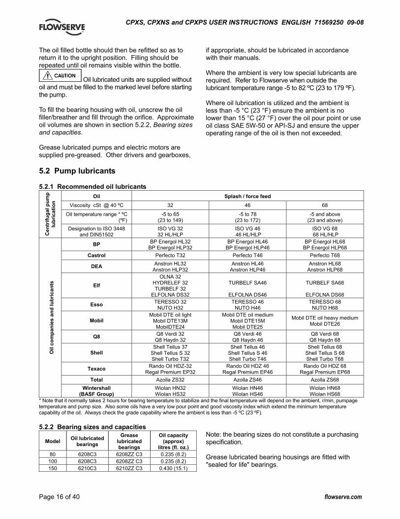
5.2 Pump lubricants 5.2.1 Recommended oil lubricants
Oil Splash / force feed Viscosity cSt @ 40 ºC 32 46 68
Oil temperature range * ºC (ºF)
-5 to 65 (23 to 149)
-5 to 78 (23 to 172)
-5 and above (23 and above)
Cen
trifu
gal p
ump
lubr
icat
ion
Designation to ISO 3448 and DIN51502
ISO VG 32 32 HL/HLP
ISO VG 46 46 HL/HLP
ISO VG 68 68 HL/HLP
BP BP Energol HL32 BP Energol HLP32
BP Energol HL46 BP Energol HLP46
BP Energol HL68 BP Energol HLP68
Castrol Perfecto T32 Perfecto T46 Perfecto T68
DEA Anstron HL32 Anstron HLP32
Anstron HL46 Anstron HLP46
Anstron HL68 Anstron HLP68
Elf OLNA 32
HYDRELEF 32 TURBELF 32
ELFOLNA DS32
TURBELF SA46
ELFOLNA DS46
TURBELF SA68
ELFOLNA DS68
Esso TERESSO 32 NUTO H32
TERESSO 46 NUTO H46
TERESSO 68 NUTO H68
Mobil Mobil DTE oil light
Mobil DTE13M MobilDTE24
Mobil DTE oil medium Mobil DTE15M Mobil DTE25
Mobil DTE oil heavy mediumMobil DTE26
Q8 Q8 Verdi 32 Q8 Haydn 32
Q8 Verdi 46 Q8 Haydn 46
Q8 Verdi 68 Q8 Haydn 68
Shell Shell Tellus 37
Shell Tellus S 32 Shell Turbo T32
Shell Tellus 46 Shell Tellus S 46 Shell Turbo T46
Shell Tellus 68 Shell Tellus S 68 Shell Turbo T68
Texaco Rando Oil HDZ-32 Regal Premium EP32
Rando Oil HDZ 46 Regal Premium EP46
Rando Oil HDZ 68 Regal Premium EP68
Total Azolla ZS32 Azolla ZS46 Azolla ZS68
Oil
com
pani
es a
nd lu
bric
ants
Wintershall (BASF Group)
Wiolan HN32 Wiolan HS32
Wiolan HN46 Wiolan HS46
Wiolan HN68 Wiolan HS68
* Note that it normally takes 2 hours for bearing temperature to stabilize and the final temperature will depend on the ambient, r/min, pumpage temperature and pump size. Also some oils have a very low pour point and good viscosity index which extend the minimum temperature capability of the oil. Always check the grade capability where the ambient is less than -5 ºC (23 ºF). 5.2.2 Bearing sizes and capacities
Model Oil lubricated bearings
Grease lubricated bearings
Oil capacity (approx)
litres (fl. oz.) 80 6208C3 6208ZZ C3 0.235 (8.2)
100 6208C3 6208ZZ C3 0.235 (8.2) 150 6210C3 6210ZZ C3 0.430 (15.1)
Note: the bearing sizes do not constitute a purchasing specification. Grease lubricated bearing housings are fitted with "sealed for life" bearings.

CPXS, CPXNS and CPXPS USER INSTRUCTIONS ENGLISH 71569250 09-08
Page 17 of 40 flowserve.com
5.2.3 Lubrication schedule 5.2.3.1 Oil lubricated bearings Normal oil change intervals are 4 000 operating hours or at least every 6 months. For pumps on hot service or in severely damp or corrosive atmosphere, the oil will require changing more frequently. Lubricant and bearing temperature analysis can be useful in optimizing lubricant change intervals. The lubricating oil should be a high quality mineral oil having foam inhibitors. Synthetic oils may also be used if checks show that the rubber oil seals will not be adversely affected. The bearing temperature may be allowed to rise to 50 ºC (90 ºF) above ambient, but should not exceed 82 ºC (180 ºF) (API 610 limit). A continuously rising temperature, or an abrupt rise, indicates a fault. Pumps which handle high temperature liquids may require their bearings to be cooled to prevent bearing temperatures exceeding their limits. 5.2.3.2 Grease lubricated bearings The bearings are sealed for life. 5.3 Open impeller clearance The impeller clearance is set in the factory. This may require adjustment because of piping attachment or increase in temperatures. For setting instructions see section 6.7, Setting impeller clearance. 5.4 Direction of rotation
Serious damage can result if the pump is started or run in the wrong direction of rotation. The pump is shipped with the coupling element removed. Ensure the direction of rotation of the motor is correct before fitting the coupling element. Direction of rotation must correspond to the direction arrow.
If maintenance work has been carried out to the site's electricity supply, the direction of rotation should be re-checked as above in case the supply phasing has been altered. 5.5 Guarding
Guarding is supplied fitted to the pump set. If this has been removed or disturbed ensure that all the protective guards are securely refitted.
5.6 Priming and auxiliary supplies 5.6.1 CPXS and CPXNS filling and priming
Ensure inlet pipe and pump casing is completely full of liquid before starting continuous duty operation. Priming may be carried out with an ejector, vacuum pump interceptor or other equipment, or by flooding from the inlet source. When in service, pumps using inlet pipes with foot valves may be primed by passing liquid back from the outlet pipe through the pump. 5.6.2 CPXPS filling and self priming
Fill the pump with liquid to be pumped, or compatible liquid, via the filling plug [30B], before starting continuous duty operation.
Pump housing filling hole. When the initial fill reaches the suction pipe, excess liquid will flow out of the casing.
Pump size Initial fill litre (US gal.) 40-40CPXPS125 2.5 (0.65) 80-80CPXPS125 6.0 (1.50) 40-40CPXPS160 3.0 (0.80) 80-80CPXPS160 6.5 (1.75) 40-40CPXPS200 5.0 (1.35) 65-65CPXPS200 8.5 (2.25) 80-80CPXPS250 12.0 (3.20)
100-100CPXPS250 36.0 (9.50) 100-100CPXPS315 14.8 (3.95) 150-150CPXPS315 18.0 (4.80)
The pump has self-priming action for which a separate air pump is not normally required. 5.6.3 Auxiliary supplies
Ensure all electrical, hydraulic, pneumatic, sealant and lubrication systems (as applicable) are connected and operational.

CPXS, CPXNS and CPXPS USER INSTRUCTIONS ENGLISH 71569250 09-08
Page 18 of 40 flowserve.com
5.7 Starting the pump 5.7.1 Starting the CPXS and CPXNS
a) Ensure flushing and/or cooling/ heating liquid supplies are turned ON, before starting pump.
b) CLOSE the outlet valve. c) OPEN all inlet valves. d) Prime the pump. e) Start motor and check the outlet pressure. f) If the pressure is satisfactory, slowly OPEN the
outlet valve.
g) Do not run the pump with the outlet valve closed for a period longer than 30 seconds.
h) If NO pressure, or LOW pressure, STOP the pump. Refer to section 7, Faults; causes and remedies for fault diagnosis.
5.7.2 Starting the CPXPS pump
a) Ensure flushing and/or cooling/ heating liquid supplies are turned ON, before starting pump.
b) CLOSE the outlet valve. c) OPEN all inlet valves.
d) Prime the pump. (See section 5.6.1.) The pump casing must initially be filled with compatible liquid before starting the unit.
e) Damage will occur if the pump is run dry or for prolonged periods with no incoming liquid.
f) Subsequent filling should not be necessary unless the pump has been emptied or drained of fluid.
g) Start the motor and, if no specific provision has been made in the delivery pipework for evacuating the primed air, open the delivery valve by approximately 10% to allow priming air to escape.
h) Check outlet pressure. i) If the pressure is satisfactory, slowly OPEN the
outlet valve. j) It is recommended that the priming time is noted.
Priming times in excess of 5 minutes will indicate a pump or system fault. Any noticeable increases in priming time on subsequent starts will also indicate a fault. Irregular use could lead to the risk of 'evaporation' of the priming fluid.
k) Do not run the pump with the outlet valve closed for a period longer than 30 seconds.
l) If the pump has to self prime the system it may take a short time before the outlet is pressurized.
m) If NO pressure, or LOW pressure, STOP the pump. Refer to section 7, Faults; causes and remedies for fault diagnosis.
5.8 Running the pump 5.8.1 Bearings
If the pumps are working in a potentially explosive atmosphere temperature or vibration monitoring at the bearings is recommended. If bearing temperatures are to be monitored it is essential that a benchmark temperature is recorded at the commissioning stage and after the bearing temperature has stabilized. • Record the bearing temperature (t) and the
ambient temperature (ta) • Estimate the likely maximum ambient
temperature (tb) • Set the alarm at (t+tb-ta+5) ºC (t+tb-ta+10) ºF
and the trip at 100 ºC (212 ºF) for oil lubrication and 105 ºC (220 ºF) for grease lubrication
It is important, particularly with grease lubrication, to keep a check on bearing temperatures. After start up the temperature rise should be gradual, reaching a maximum after approximately 1.5 to 2 hours. This temperature rise should then remain constant or marginally reduce with time. Refer to section 6.2.3.1 for further information. 5.8.2 Normal vibration levels, alarm and trip For guidance, pumps generally fall under a classification for rigid support machines within the International rotating machinery standards and the recommended maximum levels below are based on those standards.
Alarm and trip values for installed pumps should be based on the actual measurements (N) taken on the pump in the fully commissioned as new condition. Measuring vibration at regular intervals will then show any deterioration in pump or system operating conditions.
Vibration velocity – unfiltered
Horizontal pumps ≤ 15 kW mm/sec (in./sec) r.m.s.
> 15 kW mm/sec (in./sec)
r.m.s. Normal N ≤ 3.0 (0.12) ≤ 4.5 (0.18) Alarm N x 1.25 ≤ 3.8 (0.15) ≤ 5.6 (0.22) Shutdown trip N x 2.0 ≤ 6.0 (0.24) ≤ 9.0 (0.35) 5.8.3 Stop/start frequency Pump sets are normally suitable for a number of equally spaced stop/starts per hour. Generally six stop/starts per hour may be satisfactory. Refer frequent stop/starting to the motor manufacturer. Check capability of the driver and control/starting system before commissioning.

CPXS, CPXNS and CPXPS USER INSTRUCTIONS ENGLISH 71569250 09-08
Page 19 of 40 flowserve.com
Where duty and standby pumps are installed it is recommended that they are run alternately every week. 5.9 Stopping and shutdown
a) Close the outlet valve, but ensure that the pump runs in this condition for no more than a few seconds.
b) Stop the pump. c) Switch off flushing and/or cooling/heating liquid
supplies at a time appropriate to the process.
d) For prolonged shut-downs and especially when ambient temperatures are likely to drop below freezing point, the pump and any cooling and flushing arrangements must be drained or otherwise protected.
5.10 Hydraulic, mechanical and electrical duty This product has been supplied to meet the performance specifications of your purchase order, however it is understood that during the life of the product these may change. The following notes may help the user decide how to evaluate the implications of any change. If in doubt contact your nearest Flowserve office. 5.10.1 Specific gravity (SG) Pump capacity and total head in metres (feet) do not change with SG, however pressure displayed on a pressure gauge is directly proportional to SG. Power absorbed is also directly proportional to SG. It is therefore important to check that any change in SG will not overload the pump driver or over-pressurize the pump. 5.10.2 Viscosity For a given flow rate the total head reduces with increased viscosity and increases with reduced viscosity. Also for a given flow rate the power absorbed increases with increased viscosity, and reduces with reduced viscosity. It is important that checks are made with your nearest Flowserve office if changes in viscosity are planned. 5.10.3 Pump speed Changing pump speed effects flow, total head, power absorbed, NPSHR, noise and vibration. Flow varies in direct proportion to pump speed, head varies as speed ratio squared and power varies as speed ratio cubed. The new duty, however, will also be dependent on the system curve. If increasing the speed, it is important therefore to ensure the maximum pump working pressure is not exceeded, the driver is not overloaded, NPSHA > NPSHR, and that noise and vibration are within local requirements and regulations.
5.10.4 Net positive suction head (NPSHA) NPSH available (NPSHA) is a measure of the head available in the pumped liquid, above its vapour pressure, at the pump suction branch. NPSH required (NPSHR) is a measure of the head required in the pumped liquid, above its vapour pressure, to prevent the pump from cavitating. It is important that NPSHA > NPSHR. The margin between NPSHA > NPSHR should be as large as possible. If any change in NPSHA is proposed, ensure these margins are not significantly eroded. Refer to the pump performance curve to determine exact requirements particularly if flow has changed. If in doubt please consult your nearest Flowserve office for advice and details of the minimum allowable margin for your application. 5.10.5 Pumped flow Flow must not fall outside the minimum and maximum continuous safe flow shown on the pump performance curve and or data sheet. 6 MAINTENANCE 6.1 General
It is the plant operator's responsibility to ensure that all maintenance, inspection and assembly work is carried out by authorized and qualified personnel who have adequately familiarized themselves with the subject matter by studying this manual in detail. (See also section 1.6.2.) Any work on the machine must be performed when it is at a standstill. It is imperative that the procedure for shutting down the machine is followed, as described in section 5.9. On completion of work all guards and safety devices must be re-installed and made operative again. Before restarting the machine, the relevant instructions listed in section 5, Commissioning, start up, operation and shut down must be observed. Oil and grease leaks may make the ground slippery. Machine maintenance must always begin and finish by cleaning the ground and the exterior of the machine. If platforms, stairs and guard rails are required for maintenance, they must be placed for easy access to areas where maintenance and inspection are to be carried out. The positioning of these accessories must not limit access or hinder the lifting of the part to be serviced.

CPXS, CPXNS and CPXPS USER INSTRUCTIONS ENGLISH 71569250 09-08
Page 20 of 40 flowserve.com
When air or compressed inert gas is used in the maintenance process, the operator and anyone in the vicinity must be careful and have the appropriate protection. Do not spray air or compressed inert gas on skin. Do not direct an air or gas jet towards other people. Never use air or compressed inert gas to clean clothes. Before working on the pump, take measures to prevent an uncontrolled start. Put a warning board on the starting device with the words: "Machine under repair: do not start". With electric drive equipment, lock the main switch open and withdraw any fuses. Put a warning board on the fuse box or main switch with the words: "Machine under repair: do not connect". Never clean equipment with inflammable solvents or carbon tetrachloride. Protect yourself against toxic fumes when using cleaning agents. 6.2 Maintenance schedule
It is recommended that a maintenance plan and schedule is adopted, in line with these User Instructions, to include the following: a) Any auxiliary systems installed must be monitored,
if necessary, to ensure they function correctly. b) Check bearing lubricant level, and if the hours
run show a lubricant change is required. c) Check that the duty condition is in the safe
operating range for the pump. d) Check vibration, noise level and surface temperature
at the bearings to confirm satisfactory operation. e) Check dirt and dust is removed from areas around
close clearances, bearing housings and motors. f) Check coupling alignment and re-align if necessary. Our specialist service personnel can help with preventative maintenance records and provide condition monitoring for temperature and vibration to identify the onset of potential problems. If any problems are found the following sequence of actions should take place: a) Refer to section 7, Faults; causes and remedies,
for fault diagnosis. b) Ensure equipment complies with the
recommendations in this manual. c) Contact Flowserve if the problem persists.
6.2.1 Routine inspection (daily/weekly)
The following checks should be made and the appropriate action taken to remedy any deviations: a) Check operating behaviour. Ensure noise,
vibration and bearing temperatures are normal. b) Check the level and condition of oil lubricant. On
grease lubricated pumps, check running hours since last recharge of grease or complete grease change.
c) When "sealed for life" bearings are fitted it is recommended that they are renewed every 12 000 hours running life or every 2 years, whichever is the sooner.
d) Check any auxiliary supplies eg heating/cooling (if fitted) are functioning correctly.
Refer to the manuals of any associated equipment for routine checks needed.
e) Pumps having ferrous wetted components may rust internally if stood for periods longer than say 2 weeks. In such cases it is recommended that the pump shaft be turned a few revolutions at least once a week to break any rust or algae that may have built up in the clearances between rotating parts. On units where the shaft is accessible it may be turned by hand. In other cases a flick of the starter is permissible after ensuring that the pump casing is full of liquid to prevent seals, bearings etc running dry.
6.2.2 Periodic inspection (six monthly)
a) Check foundation bolts for security of attachment and corrosion.
b) Check pump running records for hourly usage to determine if bearing lubricant requires changing.
c) The coupling should be checked for correct alignment and worn driving elements.
Refer to the manuals of any associated equipment for periodic checks needed.
6.2.3 Re-lubrication Lubricant and bearing temperature analysis can be useful in optimizing lubricant change intervals. In general however, the following is recommended. 6.2.3.1 Oil lubricated bearings Normal oil change intervals are 4 000 operating hours or at least every six months. For pumps on hot service or in severely damp or corrosive atmosphere, the oil will require changing more frequently. Lubricant and bearing temperature analysis can be useful in optimizing lubricant change intervals.
CPXS, CPXNS and CPXPS USER INSTRUCTIONS ENGLISH 71569250 09-08
Page 21 of 40 flowserve.com
The lubricating oil should be a high quality oil having oxidisation and foam inhibitors, or synthetic oil. The bearing temperature may be allowed to rise to 50 ºC (90 ºF) above ambient, but should not exceed 82 ºC (180 ºF) (API 610 limit). A continuously rising temperature, or an abrupt rise, indicate a fault. Pumps that handle high temperature liquids may require their bearings to be cooled to prevent bearing temperatures exceeding their limits. 6.2.3.2 Grease lubricated bearings The bearings are sealed for life. It is recommended that they are renewed every 12 000 hours running life or every 2 years, whichever is the sooner. 6.3 Spare parts 6.3.1 Ordering of spares Flowserve keeps records of all pumps that have been supplied. When ordering spares the following information should be quoted.
1) Pump serial number. 2) Pump size. 3) Part name – taken from section 8. 4) Part number – taken from section 8. 5) Number of parts required.
The pump size and serial number are shown on the pump nameplate. To ensure continued satisfactory operation, replacement parts to the original design specification should be obtained from Flowserve. Any change to the original design specification (modification or use of a non-standard part) will invalidate the pump’s safety certification. 6.3.2 Storage of spares Spares should be stored in a clean dry area away from vibration. Inspection and re-treatment of metallic surfaces (if necessary) with preservative is recommended at 6 monthly intervals.
6.4 Recommended spares For two years operation (as per VDMA 24296).
Number of pumps (including stand-by) Part no. Designation
2 3 4 5 6/7 8/9 10(+) 2200 Impeller 1 2 3 30%
2100.1 Pump shaft 1 2 3 30% 3300.1 Bearing bush - front 1 2 3 30% 3300.2 Bearing bush - rear 1 2 3 30% 241.1 Tolerance ring 4 8 12 120%3400 Sleeve (if fitted) 2 4 6 60% 3610 Thrust collar 2 4 6 60%
4590.5 Gasket - thrust collar 4 8 12 120%
2923 Drive pin - thrust collar 4 8 12 120%
3126 Shim pack 1 2 3 30% 220 Inner rotor 1 2 3 30% 230 Outer rotor 1 2 3 30%
224.1 or 224.2
Shell (see note 1) 1 2 3 30%
3011 Ball bearing 2 4 6 60% 4590.1 Casing gasket 4 6 8 9 10 100%
4590.2 &4610
Shell O-ring set (see note 2) 2 3 4 5 6 60%
73D and 73C
Remaining gasket set 1 2 3 30%
252 Skid ring (if fitted) 1 2 3 30% Note 1: [224.1] PEEK (polymer). [224.2] metallic. Note 2: [4590.2] gasket. [4610] secondary O-ring (if fitted). 6.5 Tools required A typical range of tools that will be required to maintain these pumps is listed below. Readily available in standard tool kits, and dependent on pump size: • Open ended spanners (wrenches) to suit up to
M 24 screws/nuts • Socket spanners (wrenches), up to M 48 screws • Allen keys, up to 10 mm (A/F) • Range of screwdrivers • Soft mallet More specialized equipment: • Bearing pullers • Bearing induction heater • Dial test indicator • C-spanner (wrench) - for removing shaft nut.
(If difficulties in sourcing are encountered, consult Flowserve.) Order as follows: Part no. N.919GZ172 for Model 80 units. Part no. N.919GZ173 for Model 100 and 150 units.
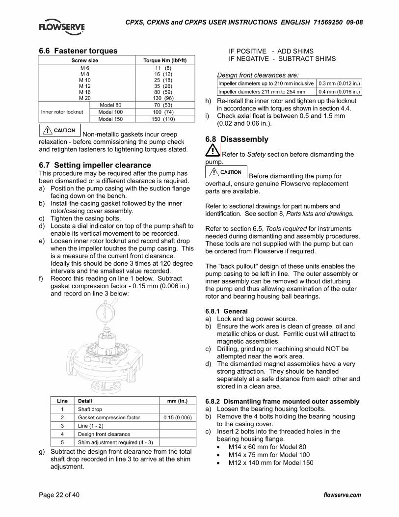
CPXS, CPXNS and CPXPS USER INSTRUCTIONS ENGLISH 71569250 09-08
Page 22 of 40 flowserve.com
6.6 Fastener torques Screw size Torque Nm (lbf•ft)
M 6 M 8
M 10 M 12 M 16 M 20
11 (8) 16 (12) 25 (18) 35 (26) 80 (59)
130 (96) Model 80 70 (53)
Model 100 100 (74) Inner rotor locknut Model 150 150 (110)
Non-metallic gaskets incur creep relaxation - before commissioning the pump check and retighten fasteners to tightening torques stated. 6.7 Setting impeller clearance This procedure may be required after the pump has been dismantled or a different clearance is required. a) Position the pump casing with the suction flange
facing down on the bench. b) Install the casing gasket followed by the inner
rotor/casing cover assembly. c) Tighten the casing bolts. d) Locate a dial indicator on top of the pump shaft to
enable its vertical movement to be recorded. e) Loosen inner rotor locknut and record shaft drop
when the impeller touches the pump casing. This is a measure of the current front clearance. Ideally this should be done 3 times at 120 degree intervals and the smallest value recorded.
f) Record this reading on line 1 below. Subtract gasket compression factor - 0.15 mm (0.006 in.) and record on line 3 below:
Line Detail mm (in.)
1 Shaft drop 2 Gasket compression factor 0.15 (0.006) 3 Line (1 - 2) 4 Design front clearance 5 Shim adjustment required (4 - 3)
g) Subtract the design front clearance from the total shaft drop recorded in line 3 to arrive at the shim adjustment.
IF POSITIVE - ADD SHIMS IF NEGATIVE - SUBTRACT SHIMS
Design front clearances are: Impeller diameters up to 210 mm inclusive 0.3 mm (0.012 in.)Impeller diameters 211 mm to 254 mm 0.4 mm (0.016 in.)
h) Re-install the inner rotor and tighten up the locknut in accordance with torques shown in section 4.4.
i) Check axial float is between 0.5 and 1.5 mm (0.02 and 0.06 in.).
6.8 Disassembly
Refer to Safety section before dismantling the pump.
Before dismantling the pump for overhaul, ensure genuine Flowserve replacement parts are available. Refer to sectional drawings for part numbers and identification. See section 8, Parts lists and drawings. Refer to section 6.5, Tools required for instruments needed during dismantling and assembly procedures. These tools are not supplied with the pump but can be ordered from Flowserve if required. The "back pullout" design of these units enables the pump casing to be left in line. The outer assembly or inner assembly can be removed without disturbing the pump end thus allowing examination of the outer rotor and bearing housing ball bearings. 6.8.1 General a) Lock and tag power source. b) Ensure the work area is clean of grease, oil and
metallic chips or dust. Ferritic dust will attract to magnetic assemblies.
c) Drilling, grinding or machining should NOT be attempted near the work area.
d) The dismantled magnet assemblies have a very strong attraction. They should be handled separately at a safe distance from each other and stored in a clean area.
6.8.2 Dismantling frame mounted outer assembly a) Loosen the bearing housing footbolts. b) Remove the 4 bolts holding the bearing housing
to the casing cover. c) Insert 2 bolts into the threaded holes in the
bearing housing flange. • M14 x 60 mm for Model 80 • M14 x 75 mm for Model 100 • M12 x 140 mm for Model 150
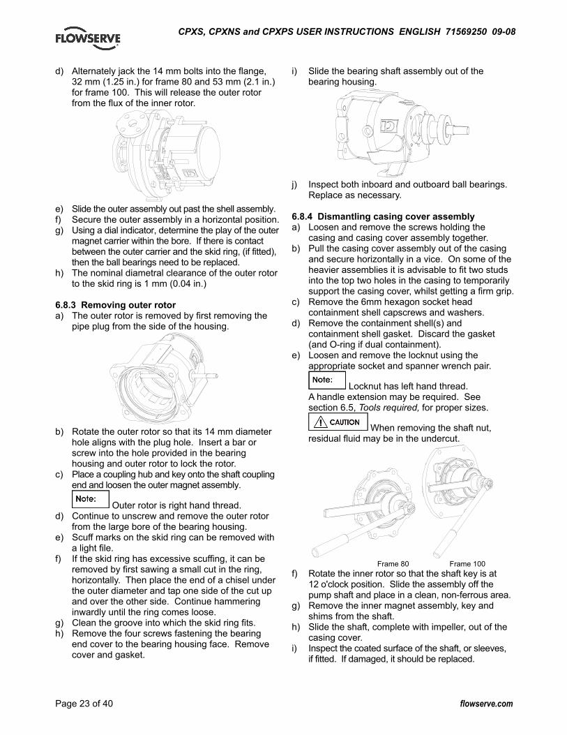
CPXS, CPXNS and CPXPS USER INSTRUCTIONS ENGLISH 71569250 09-08
Page 23 of 40 flowserve.com
d) Alternately jack the 14 mm bolts into the flange, 32 mm (1.25 in.) for frame 80 and 53 mm (2.1 in.) for frame 100. This will release the outer rotor from the flux of the inner rotor.
e) Slide the outer assembly out past the shell assembly. f) Secure the outer assembly in a horizontal position. g) Using a dial indicator, determine the play of the outer
magnet carrier within the bore. If there is contact between the outer carrier and the skid ring, (if fitted), then the ball bearings need to be replaced.
h) The nominal diametral clearance of the outer rotor to the skid ring is 1 mm (0.04 in.)
6.8.3 Removing outer rotor a) The outer rotor is removed by first removing the
pipe plug from the side of the housing.
b) Rotate the outer rotor so that its 14 mm diameter
hole aligns with the plug hole. Insert a bar or screw into the hole provided in the bearing housing and outer rotor to lock the rotor.
c) Place a coupling hub and key onto the shaft coupling end and loosen the outer magnet assembly.
Outer rotor is right hand thread. d) Continue to unscrew and remove the outer rotor
from the large bore of the bearing housing. e) Scuff marks on the skid ring can be removed with
a light file. f) If the skid ring has excessive scuffing, it can be
removed by first sawing a small cut in the ring, horizontally. Then place the end of a chisel under the outer diameter and tap one side of the cut up and over the other side. Continue hammering inwardly until the ring comes loose.
g) Clean the groove into which the skid ring fits. h) Remove the four screws fastening the bearing
end cover to the bearing housing face. Remove cover and gasket.
i) Slide the bearing shaft assembly out of the bearing housing.
j) Inspect both inboard and outboard ball bearings.
Replace as necessary. 6.8.4 Dismantling casing cover assembly a) Loosen and remove the screws holding the
casing and casing cover assembly together. b) Pull the casing cover assembly out of the casing
and secure horizontally in a vice. On some of the heavier assemblies it is advisable to fit two studs into the top two holes in the casing to temporarily support the casing cover, whilst getting a firm grip.
c) Remove the 6mm hexagon socket head containment shell capscrews and washers.
d) Remove the containment shell(s) and containment shell gasket. Discard the gasket (and O-ring if dual containment).
e) Loosen and remove the locknut using the appropriate socket and spanner wrench pair.
Locknut has left hand thread. A handle extension may be required. See section 6.5, Tools required, for proper sizes.
When removing the shaft nut, residual fluid may be in the undercut.
Frame 80 Frame 100 f) Rotate the inner rotor so that the shaft key is at
12 o'clock position. Slide the assembly off the pump shaft and place in a clean, non-ferrous area.
g) Remove the inner magnet assembly, key and shims from the shaft.
h) Slide the shaft, complete with impeller, out of the casing cover.
i) Inspect the coated surface of the shaft, or sleeves, if fitted. If damaged, it should be replaced.

CPXS, CPXNS and CPXPS USER INSTRUCTIONS ENGLISH 71569250 09-08
Page 24 of 40 flowserve.com
j) The impeller/shaft assembly may now be disassembled after first removing the sleeves and spacer, if fitted.
k) Secure the pump shaft in a vice in the vertical position using soft jaws with a pin through the bypass holes. Care must be exercised so that the coating is not damaged.
l) Loosen impeller using a strap wrench or similar.
Right hand thread.) m) Inspect BOTH sleeve bearing-bushings in the
casing cover. Polishing in the bores and thrust faces is normal. No removal is required.
n) If either bushing appears to be cracked, chipped or severely worn, remove by laying the casing cover flat face uppermost.
o) Remove two setscrews [6570.6], if fitted. (See drawings in section 8.5 and 8.6.)
p) Using an arbor, press out the bushings. q) Remove tolerance rings and discard. r) Remove the thrust collar from the inner magnet
rotor. The collar is a loose fit in the carrier bore. s) Remove the thrust collar gasket, discard and replace. 6.9 Examination of parts
Used parts must be inspected before assembly to ensure the pump will subsequently run properly. In particular, fault diagnosis is essential to enhance pump and plant reliability.
THE MAGNETS MUST BE KEPT AT A SAFE DISTANCE FROM OTHER PARTS AND TOOLS. a) Clean the internal pump parts thoroughly. b) Inspect for excessive wear, pitting, corrosion,
erosion or damage and any sealing surface irregularities. Replace as necessary.
c) For units equipped with a wash flow strainer, be sure to clean the filter removing any debris that may be blocking the strainer holes.
d) Clean lubrication holes in the casing cover, inner magnet carrier and shaft.
e) On the casing cover, inspect the injection, vent, drain and return holes. Clean if necessary.
f) The balance holes of the inner rotor should also be inspected and cleared of any debris.
g) Replace all gaskets and O-rings.
h) Check the driver manufacturer's instructions. As a minimum, check the bearings and shaft for straightness.
i) The lubricant, bearings and bearing seals in the motor should be inspected for contamination and damage.
j) Ensure all lubrication passageways in the bearing housing are clean and free from damage.
6.10 Magnets Demagnetization of the magnet material can be the result of either high operating temperatures around the magnet assemblies or decoupled magnets operating around a metallic containment shell. High ambient temperatures are detrimental to the attraction properties of the magnets. The inner magnet assembly is most susceptible to high operating temperatures and cannot tolerate operation above its upper critical temperature limit.
If decoupling has occurred or if a system upset has caused the temperature limits to be exceeded, the original strength of the magnets may have decreased. The following torque test procedure should be followed in such a situation. Magnet torque test procedure a) Remove the casing from the pump. b) Lock the outer rotor assembly in position. Insert
bolt in assembly hole. c) Remove the impeller by using a strap wrench
around the periphery of the impeller. Turn counterclockwise.
d) Install a shaft adapter on the shaft threaded connection. • Models 80 and 100 M22 -1.5 pitch • Model 150 M30 -1.5 pitch
e) Secure the bearing housing on a stable worktable. f) Use a torque wrench on the nut and turn
clockwise to measure the force required to break the magnetic coupling. Adjust the wrench setting such that the torque value is determined prior to breaking the magnetic couple. This is the torque capability of the magnetic coupling.
Factory torque specification Minimum torque Nm (lbf•ft) Model Series
Neodymium Samarium cobalt 80 8 13 (9.6) 11 (8.1) 80 15 27 (20) 24 (17.7)
100 25 45 (33) 40 (29.5) 100 50 90 (66) 80 (59) 150 50 80 (59) 70 (51.5) 150 100 160 (118) 140 (103) 150 150 240 (177) 210 (154.5)

CPXS, CPXNS and CPXPS USER INSTRUCTIONS ENGLISH 71569250 09-08
Page 25 of 40 flowserve.com
6.11 Assembly To assemble the pump consult the sectional drawings. See section 8, Parts lists and drawings. Ensure threads, gasket and O-ring mating faces are clean. Apply thread sealant to non-face sealing pipe thread fittings. 6.11.1 Outer assembly - bearing housing assembly a) If removed, replace the skid ring. b) If the radial ball bearings are found to be
damaged, press two new bearings onto the shaft.
Be sure to press on only the inner race of the bearing whilst pressing it onto the shaft. Press bearings up to the shaft shoulders.
c) Install the bearing/shaft assembly into the bore of the bearing housing.
d) Seat the end cover gasket. e) Bolt bearing end cover to bearing housing face.
Be sure that the oil return grooves on the gasket and end cover line up.
f) Tighten screws to 13 Nm (9.6 lbf•ft) torque. g) Turn the shaft coupling end to ensure freedom of
rotation. h) Install the flinger over the shaft.
Be sure that the flinger is not pressed down hard against the bearing end cover.
i) Position the bearing housing horizontally. j) Coat the outer magnet rotor threads with anti-
seize compound. k) Insert outer magnet rotor into the large bore of the
bearing housing and screw onto the frame shaft.
Right hand thread. l) Insert a bar or screw into the holes provided in the
bearing housing and outer rotor to lock the rotor. m) Place a coupling hub and key onto the shaft
coupling end and torque the outer magnet assembly to 54 Nm (40 lbf•ft).
n) Remove the bar or screw and check shaft for freedom of rotation.
o) Re-install the pipe plug. 6.11.2 Inner assembly - casing cover assembly a) If the sleeve bearing bushings were not removed
during dismantling, proceed to Rotor assembly, section 6.11.3.
b) The inboard tolerance ring must be trimmed to length using tin snips. This is due to the difference in diameter of the two bushings. Trim off three corrugations prior to placement in the casing cover.
c) There must be a minimum gap of 1.5 mm (0.06 in.) between the cut ends of the tolerance ring before assembly of bushes.
d) Install the cut tolerance ring into the inner bore.
Rotate the ring to guarantee it is secure. e) Position the casing cover with "top" designation at
12 o'clock position. f) Insert the front bearing bushing so that the
lubrication groove is at a 9 o'clock position. The face with the white spot should be visible. The opposite face is lapped and should locate against the shoulder in the casing cover.
g) Press in the front bearing bushing up to the shoulder in the casing cover.
h) Fit bearing bush spacer (if appropriate). i) Insert the second tolerance ring, rotating it for a
secure fit. j) Insert rear bearing bushing until resistance is felt. k) Position the bushing so that one lubrication
groove is at the 6 o'clock position and press in up to the shoulder in the casing cover. The face with the white spot should mate up to the shoulder in the casing cover.
l) If a bearing bush spacer has been fitted, secure with two radial socket head setscrews.
6.11.3 Rotor assembly a) Thoroughly clean and degrease impeller and
shaft threads. b) Install the impeller on the pump shaft, after first
applying anti-seize compound (which does not contain copper) at the impeller to shaft thread to assist in subsequent removal.
c) Secure the pump shaft in a vice in the vertical position using soft jaws with a pin through the bypass holes. Care must be exercised so that the coating is not damaged.
d) Tighten the impeller using a strap wrench or similar.
e) If fitted, slide sleeves and spacer onto shaft. f) Position the casing cover upright with the through
bore in the horizontal plane and "TOP" designation at 12 o'clock.
g) Slide the shaft through the casing cover.
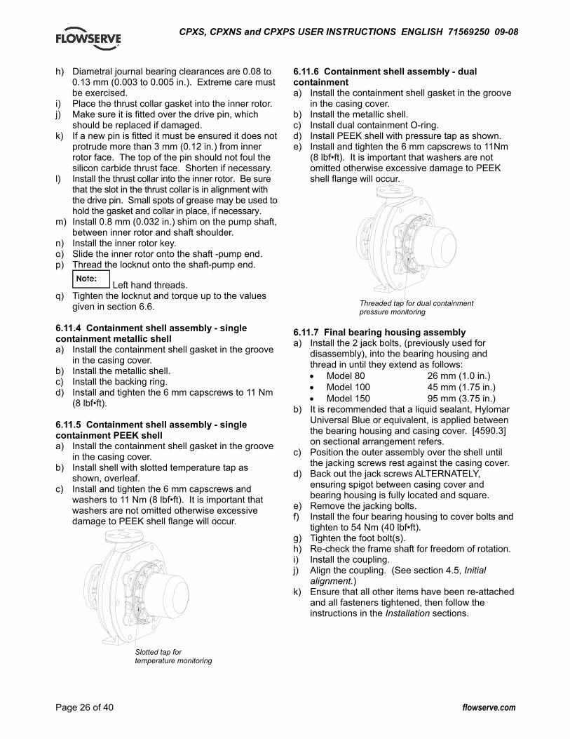
CPXS, CPXNS and CPXPS USER INSTRUCTIONS ENGLISH 71569250 09-08
Page 26 of 40 flowserve.com
h) Diametral journal bearing clearances are 0.08 to 0.13 mm (0.003 to 0.005 in.). Extreme care must be exercised.
i) Place the thrust collar gasket into the inner rotor. j) Make sure it is fitted over the drive pin, which
should be replaced if damaged. k) If a new pin is fitted it must be ensured it does not
protrude more than 3 mm (0.12 in.) from inner rotor face. The top of the pin should not foul the silicon carbide thrust face. Shorten if necessary.
l) Install the thrust collar into the inner rotor. Be sure that the slot in the thrust collar is in alignment with the drive pin. Small spots of grease may be used to hold the gasket and collar in place, if necessary.
m) Install 0.8 mm (0.032 in.) shim on the pump shaft, between inner rotor and shaft shoulder.
n) Install the inner rotor key. o) Slide the inner rotor onto the shaft -pump end. p) Thread the locknut onto the shaft-pump end.
Left hand threads. q) Tighten the locknut and torque up to the values
given in section 6.6. 6.11.4 Containment shell assembly - single containment metallic shell a) Install the containment shell gasket in the groove
in the casing cover. b) Install the metallic shell. c) Install the backing ring. d) Install and tighten the 6 mm capscrews to 11 Nm
(8 lbf•ft). 6.11.5 Containment shell assembly - single containment PEEK shell a) Install the containment shell gasket in the groove
in the casing cover. b) Install shell with slotted temperature tap as
shown, overleaf. c) Install and tighten the 6 mm capscrews and
washers to 11 Nm (8 lbf•ft). It is important that washers are not omitted otherwise excessive damage to PEEK shell flange will occur.
Slotted tap for temperature monitoring
6.11.6 Containment shell assembly - dual containment a) Install the containment shell gasket in the groove
in the casing cover. b) Install the metallic shell. c) Install dual containment O-ring. d) Install PEEK shell with pressure tap as shown. e) Install and tighten the 6 mm capscrews to 11Nm
(8 lbf•ft). It is important that washers are not omitted otherwise excessive damage to PEEK shell flange will occur.
Threaded tap for dual containment pressure monitoring
6.11.7 Final bearing housing assembly a) Install the 2 jack bolts, (previously used for
disassembly), into the bearing housing and thread in until they extend as follows: • Model 80 26 mm (1.0 in.) • Model 100 45 mm (1.75 in.) • Model 150 95 mm (3.75 in.)
b) It is recommended that a liquid sealant, Hylomar Universal Blue or equivalent, is applied between the bearing housing and casing cover. [4590.3] on sectional arrangement refers.
c) Position the outer assembly over the shell until the jacking screws rest against the casing cover.
d) Back out the jack screws ALTERNATELY, ensuring spigot between casing cover and bearing housing is fully located and square.
e) Remove the jacking bolts. f) Install the four bearing housing to cover bolts and
tighten to 54 Nm (40 lbf•ft). g) Tighten the foot bolt(s). h) Re-check the frame shaft for freedom of rotation. i) Install the coupling. j) Align the coupling. (See section 4.5, Initial
alignment.) k) Ensure that all other items have been re-attached
and all fasteners tightened, then follow the instructions in the Installation sections.
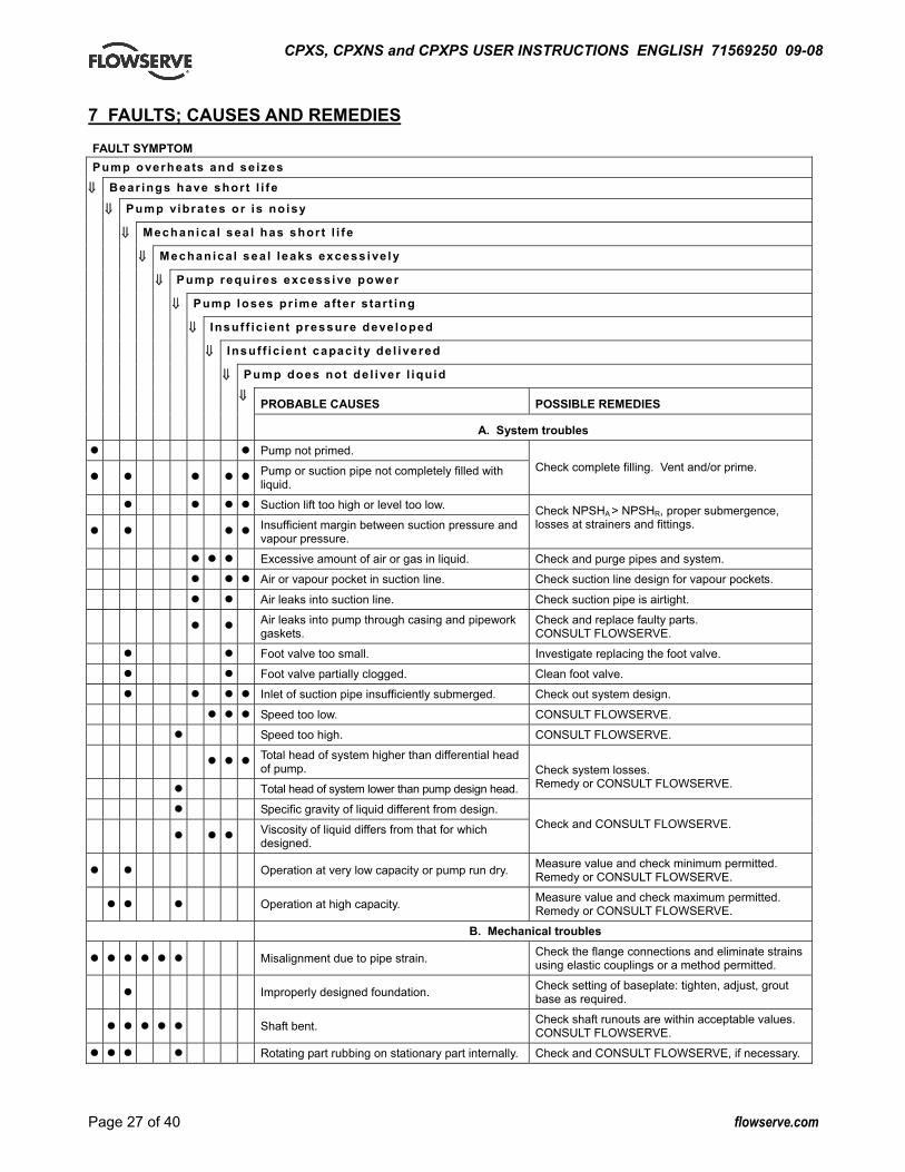
CPXS, CPXNS and CPXPS USER INSTRUCTIONS ENGLISH 71569250 09-08
Page 27 of 40 flowserve.com
7 FAULTS; CAUSES AND REMEDIES FAULT SYMPTOM Pump overheats and se izes
⇓⇓ Bear ings have shor t l i fe
⇓⇓ Pump vibra tes or is no isy
⇓⇓ Mechanical sea l has shor t l i fe
⇓⇓ Mechanical sea l leaks excess ive ly
⇓⇓ Pump requi res excess ive pow er
⇓⇓ Pump loses pr ime a fter s tar t ing
⇓⇓ Insuf f ic ient pressure deve loped
⇓⇓ Insuf f ic ient capac i ty de l ivered
⇓⇓ Pump does not de l i ver l iqu id
⇓⇓ PROBABLE CAUSES POSSIBLE REMEDIES A. System troubles
Pump not primed.
Pump or suction pipe not completely filled with liquid.
Check complete filling. Vent and/or prime.
Suction lift too high or level too low.
Insufficient margin between suction pressure and vapour pressure.
Check NPSHA > NPSHR, proper submergence, losses at strainers and fittings.
Excessive amount of air or gas in liquid. Check and purge pipes and system.
Air or vapour pocket in suction line. Check suction line design for vapour pockets.
Air leaks into suction line. Check suction pipe is airtight.
Air leaks into pump through casing and pipework gaskets.
Check and replace faulty parts. CONSULT FLOWSERVE.
Foot valve too small. Investigate replacing the foot valve.
Foot valve partially clogged. Clean foot valve.
Inlet of suction pipe insufficiently submerged. Check out system design.
Speed too low. CONSULT FLOWSERVE.
Speed too high. CONSULT FLOWSERVE.
Total head of system higher than differential head of pump.
Total head of system lower than pump design head. Check system losses. Remedy or CONSULT FLOWSERVE.
Specific gravity of liquid different from design.
Viscosity of liquid differs from that for which designed.
Check and CONSULT FLOWSERVE.
Operation at very low capacity or pump run dry. Measure value and check minimum permitted. Remedy or CONSULT FLOWSERVE.
Operation at high capacity. Measure value and check maximum permitted. Remedy or CONSULT FLOWSERVE.
B. Mechanical troubles
Misalignment due to pipe strain. Check the flange connections and eliminate strains using elastic couplings or a method permitted.
Improperly designed foundation. Check setting of baseplate: tighten, adjust, grout base as required.
Shaft bent. Check shaft runouts are within acceptable values. CONSULT FLOWSERVE.
Rotating part rubbing on stationary part internally. Check and CONSULT FLOWSERVE, if necessary.
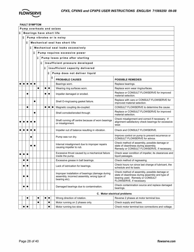
CPXS, CPXNS and CPXPS USER INSTRUCTIONS ENGLISH 71569250 09-08
Page 28 of 40 flowserve.com
FAULT SYMPTOM Pump overheats and se izes
⇓⇓ Bear ings have shor t l i fe
⇓⇓ Pump vibra tes or is no isy
⇓⇓ Mechanical sea l has shor t l i fe
⇓⇓ Mechanical sea l leaks excess ive ly
⇓⇓ Pump requi res excess ive pow er
⇓⇓ Pump loses pr ime a fter s tar t ing
⇓⇓ Insuf f ic ient pressure deve loped
⇓⇓ Insuf f ic ient capac i ty de l ivered
⇓⇓ Pump does not de l i ver l iqu id
⇓⇓ PROBABLE CAUSES POSSIBLE REMEDIES Bearings worn. Replace bearings.
Wearing ring surfaces worn. Replace worn wear ring/surfaces.
Impeller damaged or eroded. Replace or CONSULT FLOWSERVE for improved material selection.
Shell O-ring/casing gasket failure. Replace with care or CONSULT FLOWSERVE for improved material selection.
Magnetic coupling de-coupled. CONSULT FLOWSERVE to determine the cause.
Shell corroded/eroded through Replace or CONSULT FLOWSERVE for improved material selection.
Shaft running off centre because of worn bearings or misalignment.
Check misalignment and correct if necessary. If alignment satisfactory check bearings for excessive wear.
Impeller out of balance resulting in vibration. Check and CONSULT FLOWSERVE.
Pump was run dry. Improve control on pump to prevent recurrence or CONSULT FLOWSERVE for advice.
Internal misalignment due to improper repairs causing impeller to rub.
Check method of assembly, possible damage or state of cleanliness during assembly. Remedy or CONSULT FLOWSERVE, if necessary.
Excessive thrust caused by a mechanical failure inside the pump.
Check wear condition of impeller, its clearances and liquid passages.
Excessive grease in ball bearings. Check method of regreasing.
Lack of lubrication for bearings. Check hours run since last change of lubricant, the schedule and its basis.
Improper installation of bearings (damage during assembly, incorrect assembly, wrong type of bearing etc).
Check method of assembly, possible damage or state of cleanliness during assembly and type of bearing used. Remedy or CONSULT FLOWSERVE, if necessary.
Damaged bearings due to contamination. Check contamination source and replace damaged bearings.
C. Motor electrical problems Wrong direction of rotation. Reverse 2 phases at motor terminal box.
Motor running on 2 phases only. Check supply and fuses.
Motor running too slow. Check motor terminal box connections and voltage.
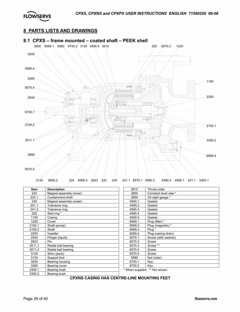
CPXS, CPXNS and CPXPS USER INSTRUCTIONS ENGLISH 71569250 09-08
Page 29 of 40 flowserve.com
8 PARTS LISTS AND DRAWINGS 8.1 CPXS – frame mounted – coated shaft – PEEK shell
Item Description 220 Magnet assembly (inner)
224.1 Containment shell 230 Magnet assembly (outer)
241.1 Tolerance ring 241.2 Tolerance ring 252 Skid ring *
1100 Casing 1220 Cover
2100.1 Shaft (pump) 2100.2 Shaft 2200 Impeller 2540 Flinger (liquid) 2923 Pin
3011.1 Radial ball bearing 3011.2 Radial ball bearing 3126 Shim (pack) 3134 Support foot 3200 Bearing housing 3260 Bearing cover
3300.1 Bearing bush 3300.2 Bearing bush
3610 Thrust collar 3855 Constant level oiler * 3856 Oil sight gauge *
4590.1 Gasket 4590.2 Gasket 4590.3 Gasket 4590.4 Gasket 4590.5 Gasket 6569.1 Plug (filler) * 6569.2 Plug (magnetic) * 6569.3 Plug * 6569.4 Plug (casing drain) 6570.1 Screw (with washer) 6570.2 Screw 6570.3 Screw ** 6570.4 Screw 6570.5 Screw 6580 Nut (rotor)
6700.1 Key 6700.2 Key
* When supplied. ** Not shown.
CPXNS CASING HAS CENTRE-LINE MOUNTING FEET
3855 6569.1 6580 6700.2 3126 4590.5 3610 252 6570.2 1220
3134 6569.2 224 6569.3 2923 220 230 241.1 6570.1 4590.3 4590.2 4590.1 241.1 3300.1
1100 2200 2100.1 3300.2 6569.4
3200
4590.4
3260
6570.4
2540
6700.1
2100.2
3011.1
3856
6570.5

CPXS, CPXNS and CPXPS USER INSTRUCTIONS ENGLISH 71569250 09-08
Page 30 of 40 flowserve.com
8.2 CPXS – frame mounted – sleeved shaft – PEEK shell
Item Description 220 Magnet assembly (inner)
224.1 Containment shell 230 Magnet assembly (outer)
241.1 Tolerance ring 241.2 Tolerance ring 252 Skid ring *
1100 Casing 1220 Cover
2100.1 Shaft 2100.2 Shaft 2200 Impeller
2460.1 Spacer sleeve (shaft) 2540 Flinger (liquid) 2923 Pin
3011.1 Radial ball bearing 3011.2 Radial ball bearing 3126 Shim (pack) 3134 Support foot 3200 Bearing housing 3260 Bearing cover
3300.1 Bearing bush 3300.2 Bearing bush
3400 Bearing sleeve 3610 Thrust collar 3855 Constant level oiler * 3856 Oil sight gauge *
4590.1 Gasket 4590.2 Gasket 4590.3 Gasket 4590.4 Gasket 4590.5 Gasket 6569.1 Plug (filler) * 6569.2 Plug (magnetic) * 6569.3 Plug * 6569.4 Plug 6570.1 Screw (with washer) 6570.2 Screw 6570.3 Screw ** 6570.4 Screw 6570.5 Screw 6580 Nut (rotor)
6700.1 Key 6700.2 Key
* When supplied. ** Not shown.
CPXNS CASING HAS CENTRE-LINE MOUNTING FEET
3855 6569.1 6580 6700.2 3126 4590.5 3610 3400 2460.1 252 6570.2 1220
3134 6569.2 224 6569.3 2923 220 230 241.1 6570.1 4590.3 4590.2 4590.1 241.1 3300.1
3400 1100 2200 2100.1 3300.2 6569.4
3200
4590.4
3260
6570.4
2540
6700.1
2100.2
3011.1
3856
6570.5
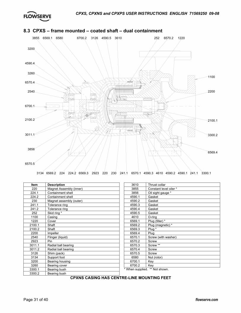
CPXS, CPXNS and CPXPS USER INSTRUCTIONS ENGLISH 71569250 09-08
Page 31 of 40 flowserve.com
8.3 CPXS – frame mounted – coated shaft – dual containment
Item Description 220 Magnet Assembly (inner)
224.1 Containment shell 224.2 Containment shell 230 Magnet assembly (outer)
241.1 Tolerance ring 241.2 Tolerance ring 252 Skid ring *
1100 Casing 1220 Cover
2100.1 Shaft 2100.2 Shaft 2200 Impeller 2540 Flinger (liquid) 2923 Pin
3011.1 Radial ball bearing 3011.2 Radial ball bearing 3126 Shim (pack) 3134 Support foot 3200 Bearing housing 3260 Bearing cover
3300.1 Bearing bush 3300.2 Bearing bush
3610 Thrust collar 3855 Constant level oiler * 3856 Oil sight gauge *
4590.1 Gasket 4590.2 Gasket 4590.3 Gasket 4590.4 Gasket 4590.5 Gasket 4610 O-ring
6569.1 Plug (filler) * 6569.2 Plug (magnetic) * 6569.3 Plug * 6569.4 Plug 6570.1 Screw (with washer) 6570.2 Screw 6570.3 Screw ** 6570.4 Screw 6570.5 Screw 6580 Nut (rotor)
6700.1 Key 6700.2 Key
* When supplied. ** Not shown.
CPXNS CASING HAS CENTRE-LINE MOUNTING FEET
3134 6569.2 224 224.2 6569.3 2923 220 230 241.1 6570.1 4590.3 4610 4590.2 4590.1 241.1 3300.1
1100 2200 2100.1 3300.2 6569.4
3855 6569.1 6580 6700.2 3126 4590.5 3610 252 6570.2 1220
3200
4590.4
3260
6570.4
2540
6700.1
2100.2
3011.1
3856
6570.5
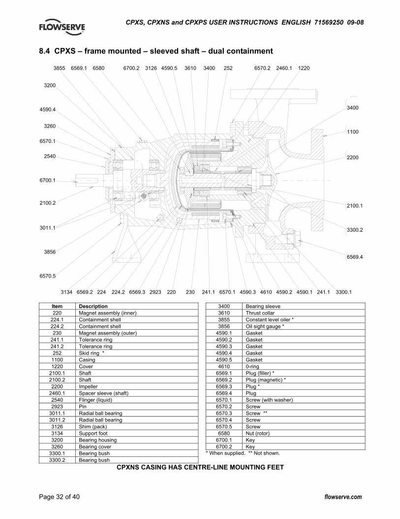
CPXS, CPXNS and CPXPS USER INSTRUCTIONS ENGLISH 71569250 09-08
Page 32 of 40 flowserve.com
8.4 CPXS – frame mounted – sleeved shaft – dual containment
Item Description 220 Magnet assembly (inner)
224.1 Containment shell 224.2 Containment shell 230 Magnet assembly (outer)
241.1 Tolerance ring 241.2 Tolerance ring 252 Skid ring *
1100 Casing 1220 Cover
2100.1 Shaft 2100.2 Shaft 2200 Impeller
2460.1 Spacer sleeve (shaft) 2540 Flinger (liquid) 2923 Pin
3011.1 Radial ball bearing 3011.2 Radial ball bearing 3126 Shim (pack) 3134 Support foot 3200 Bearing housing 3260 Bearing cover
3300.1 Bearing bush 3300.2 Bearing bush
3400 Bearing sleeve 3610 Thrust collar 3855 Constant level oiler * 3856 Oil sight gauge *
4590.1 Gasket 4590.2 Gasket 4590.3 Gasket 4590.4 Gasket 4590.5 Gasket 4610 0-ring
6569.1 Plug (filler) * 6569.2 Plug (magnetic) * 6569.3 Plug * 6569.4 Plug 6570.1 Screw (with washer) 6570.2 Screw 6570.3 Screw ** 6570.4 Screw 6570.5 Screw 6580 Nut (rotor)
6700.1 Key 6700.2 Key
* When supplied. ** Not shown.
CPXNS CASING HAS CENTRE-LINE MOUNTING FEET
3855 6569.1 6580 6700.2 3126 4590.5 3610 3400 252 6570.2 2460.1 1220
3134 6569.2 224 224.2 6569.3 2923 220 230 241.1 6570.1 4590.3 4610 4590.2 4590.1 241.1 3300.1
3400 1100 2200 2100.1 3300.2 6569.4
3200
4590.4
3260
6570.1
2540
6700.1
2100.2
3011.1
3856
6570.5
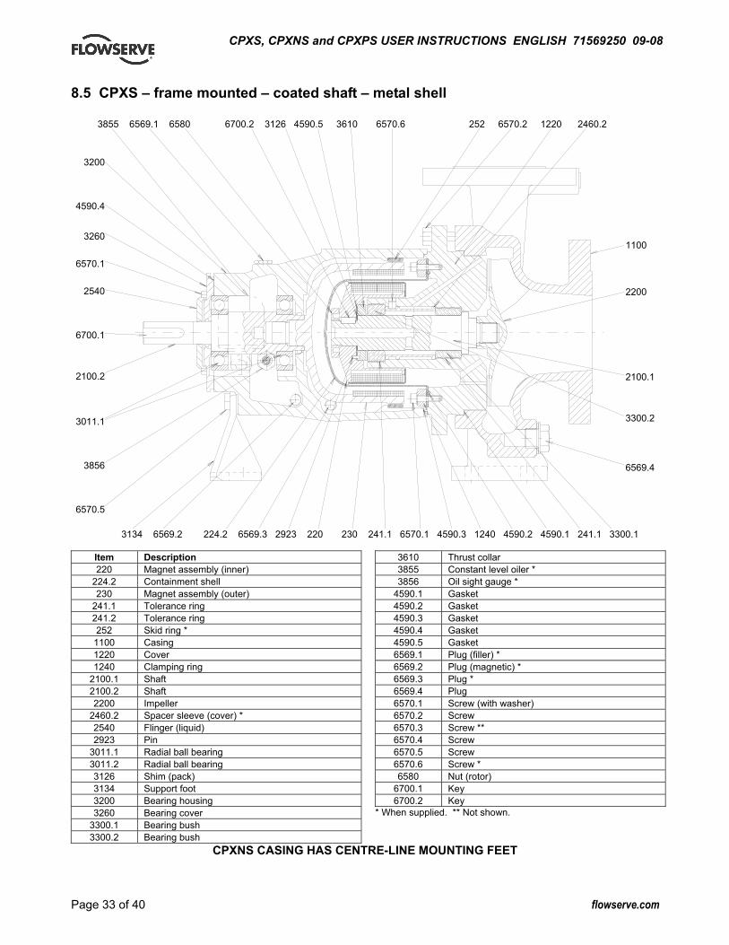
CPXS, CPXNS and CPXPS USER INSTRUCTIONS ENGLISH 71569250 09-08
Page 33 of 40 flowserve.com
8.5 CPXS – frame mounted – coated shaft – metal shell
Item Description 220 Magnet assembly (inner)
224.2 Containment shell 230 Magnet assembly (outer)
241.1 Tolerance ring 241.2 Tolerance ring 252 Skid ring *
1100 Casing 1220 Cover 1240 Clamping ring
2100.1 Shaft 2100.2 Shaft 2200 Impeller
2460.2 Spacer sleeve (cover) * 2540 Flinger (liquid) 2923 Pin
3011.1 Radial ball bearing 3011.2 Radial ball bearing 3126 Shim (pack) 3134 Support foot 3200 Bearing housing 3260 Bearing cover
3300.1 Bearing bush 3300.2 Bearing bush
3610 Thrust collar 3855 Constant level oiler * 3856 Oil sight gauge *
4590.1 Gasket 4590.2 Gasket 4590.3 Gasket 4590.4 Gasket 4590.5 Gasket 6569.1 Plug (filler) * 6569.2 Plug (magnetic) * 6569.3 Plug * 6569.4 Plug 6570.1 Screw (with washer) 6570.2 Screw 6570.3 Screw ** 6570.4 Screw 6570.5 Screw 6570.6 Screw * 6580 Nut (rotor)
6700.1 Key 6700.2 Key
* When supplied. ** Not shown.
CPXNS CASING HAS CENTRE-LINE MOUNTING FEET
1100 2200 2100.1 3300.2 6569.4
3200
4590.4
3260
6570.1
2540
6700.1
2100.2
3011.1
3856
6570.5
3134 6569.2 224.2 6569.3 2923 220 230 241.1 6570.1 4590.3 1240 4590.2 4590.1 241.1 3300.1
3855 6569.1 6580 6700.2 3126 4590.5 3610 6570.6 252 6570.2 1220 2460.2
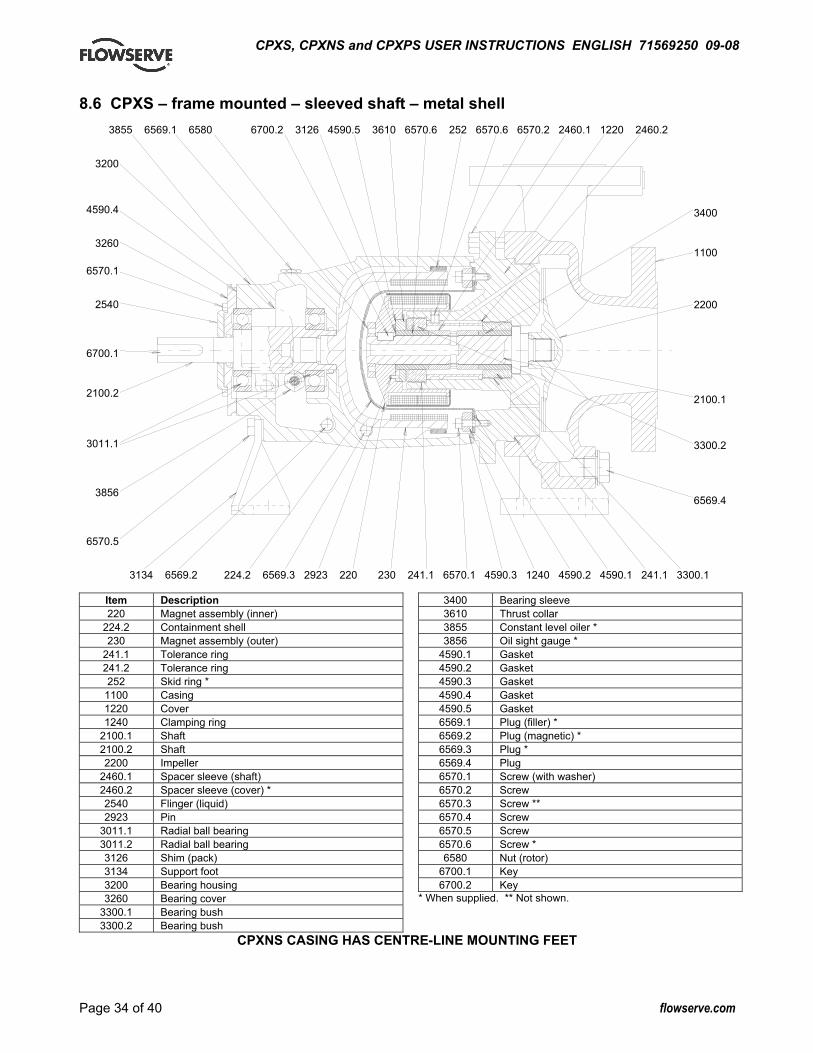
CPXS, CPXNS and CPXPS USER INSTRUCTIONS ENGLISH 71569250 09-08
Page 34 of 40 flowserve.com
8.6 CPXS – frame mounted – sleeved shaft – metal shell
Item Description 220 Magnet assembly (inner)
224.2 Containment shell 230 Magnet assembly (outer)
241.1 Tolerance ring 241.2 Tolerance ring 252 Skid ring *
1100 Casing 1220 Cover 1240 Clamping ring
2100.1 Shaft 2100.2 Shaft 2200 Impeller
2460.1 Spacer sleeve (shaft) 2460.2 Spacer sleeve (cover) * 2540 Flinger (liquid) 2923 Pin
3011.1 Radial ball bearing 3011.2 Radial ball bearing 3126 Shim (pack) 3134 Support foot 3200 Bearing housing 3260 Bearing cover
3300.1 Bearing bush 3300.2 Bearing bush
3400 Bearing sleeve 3610 Thrust collar 3855 Constant level oiler * 3856 Oil sight gauge *
4590.1 Gasket 4590.2 Gasket 4590.3 Gasket 4590.4 Gasket 4590.5 Gasket 6569.1 Plug (filler) * 6569.2 Plug (magnetic) * 6569.3 Plug * 6569.4 Plug 6570.1 Screw (with washer) 6570.2 Screw 6570.3 Screw ** 6570.4 Screw 6570.5 Screw 6570.6 Screw * 6580 Nut (rotor)
6700.1 Key 6700.2 Key
* When supplied. ** Not shown.
CPXNS CASING HAS CENTRE-LINE MOUNTING FEET
3855 6569.1 6580 6700.2 3126 4590.5 3610 6570.6 252 6570.6 6570.2 2460.1 1220 2460.2
3134 6569.2 224.2 6569.3 2923 220 230 241.1 6570.1 4590.3 1240 4590.2 4590.1 241.1 3300.1
3400 1100 2200 2100.1 3300.2 6569.4
3200
4590.4
3260
6570.1
2540
6700.1
2100.2
3011.1
3856
6570.5

CPXS, CPXNS and CPXPS USER INSTRUCTIONS ENGLISH 71569250 09-08
Page 35 of 40 flowserve.com
8.7 CPXPS – frame mounted – coated shaft – PEEK shell
30B
1
2
237
6
30A
23953C7267 73E6619B 76 252
Item Description 220 Magnet assembly (inner)
224.1 Containment shell 230 Magnet assembly (outer)
241.1 Tolerance ring 241.2 Tolerance ring 252 Skid ring *
1100 Casing 1220 Cover
2100.1 Shaft 2100.2 Shaft 2200 Impeller 2540 Flinger (liquid) 2923 Pin
3011.1 Radial ball bearing 3011.2 Radial ball bearing 3126 Shim (pack) 3134 Support foot 3200 Bearing housing 3260 Bearing cover
3300.1 Bearing bush 3300.2 Bearing bush
3610 Thrust collar 3855 Constant level oiler * 3856 Oil sight gauge *
4590.1 Gasket 4590.2 Gasket 4590.3 Gasket 4590.4 Gasket 4590.5 Gasket 6569.1 Plug (filler) * 6569.2 Plug (magnetic) * 6569.3 Plug * 6569.4 Plug 6569.5 Plug 6570.1 Screw (with washer) 6570.2 Screw 6570.3 Screw ** 6570.4 Screw 6570.5 Screw 6580 Nut (rotor)
6700.1 Key 6700.2 Key
* When supplied. ** Not shown. CPXNS CASING HAS CENTRE-LINE MOUNTING FEET
3134 6569.2 224 6569.3 2923 220 230 241.1 6570.1 4590.3 4590.2 4590.1 241.1 3300.1
3855
3200
4590.4
3260
6570.1
2540
6700.1
2100.2
3011.1
3856
6570.5
6569.1 6580 6700.2 3126 4590.5 3610 252 6570.2 1220 6569.5 1100
2200 2100.1 3300.2 6569.4

CPXS, CPXNS and CPXPS USER INSTRUCTIONS ENGLISH 71569250 09-08
Page 36 of 40 flowserve.com
8.8 CPXPS – frame mounted – sleeved shaft – PEEK shell
1
306
2
6
237
30A
Item Description 220 Magnet assembly (inner)
224.1 Containment shell 230 Magnet assembly (outer)
241.1 Tolerance ring 241.2 Tolerance ring 252 Skid ring *
1100 Casing 1220 Cover
2100.1 Shaft 2100.2 Shaft 2200 Impeller
2460.1 Spacer sleeve (shaft) 2540 Flinger (liquid) 2923 Pin
3011.1 Radial ball bearing 3011.2 Radial ball bearing 3126 Shim (pack) 3134 Support foot 3200 Bearing housing 3260 Bearing cover
3300.1 Bearing bush 3300.2 Bearing bush 3400 Bearing sleeve
3610 Thrust collar 3855 Constant level oiler * 3856 Oil sight gauge *
4590.1 Gasket 4590.2 Gasket 4590.3 Gasket 4590.4 Gasket 4590.5 Gasket 6569.1 Plug (filler) * 6569.2 Plug (magnetic) * 6569.3 Plug * 6569.4 Plug 6569.5 Plug 6570.1 Screw (with washer) 6570.2 Screw 6570.3 Screw ** 6570.4 Screw 6570.5 Screw 6580 Nut (rotor)
6700.1 Key 6700.2 Key
* When supplied. ** Not shown.
CPXNS CASING HAS CENTRE-LINE MOUNTING FEET
3855
3200
4590.4
3260
6570.1
2540
6700.1
2100.2
3011.1
3856
6570.5
6569.1 6580 6700.2 3126 4590.5 3610 3400 2460.1 252 6570.2 1220 6569.5 1100 3400
2200 2100.1 3300.2 6569.4
3134 6569.2 224 6569.3 2923 220 230 241.1 6570.1 4590.3 4590.2 4590.1 241.1 3300.1
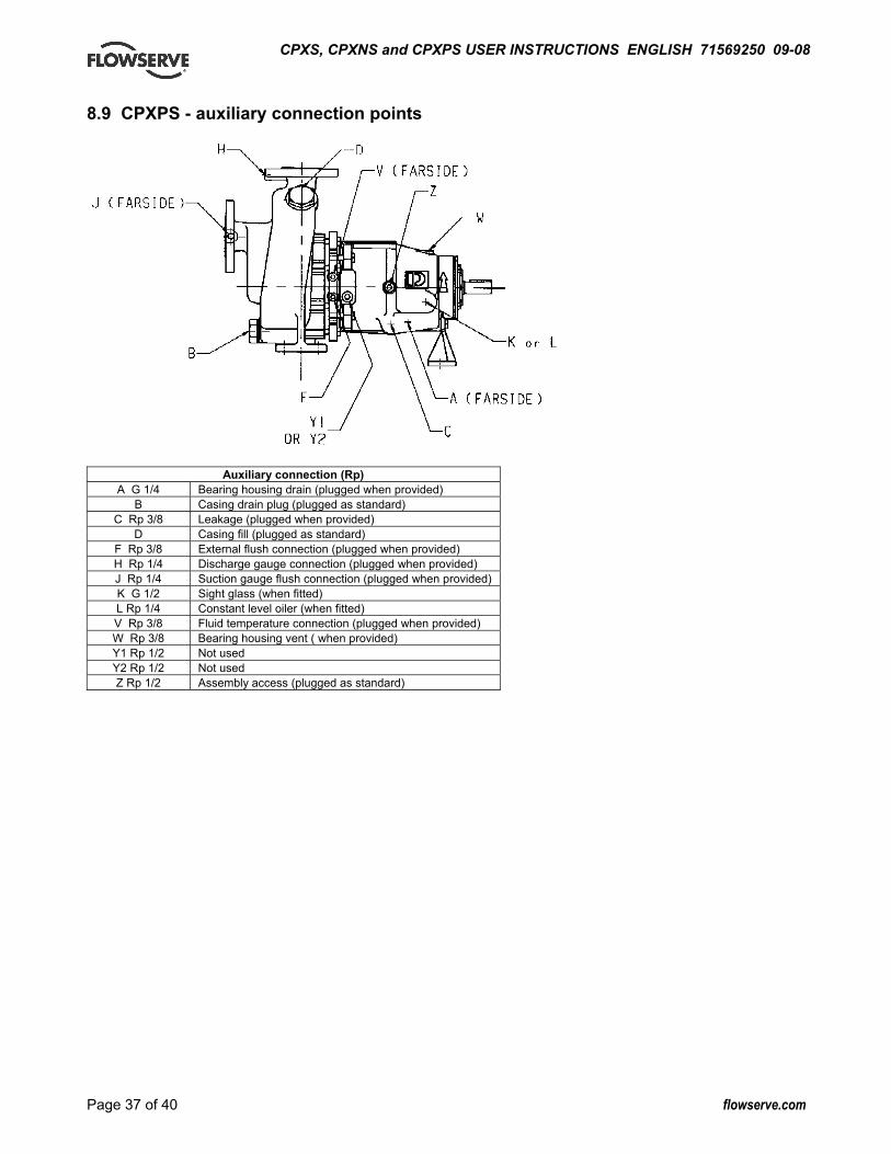
CPXS, CPXNS and CPXPS USER INSTRUCTIONS ENGLISH 71569250 09-08
Page 37 of 40 flowserve.com
8.9 CPXPS - auxiliary connection points
Auxiliary connection (Rp) A G 1/4 Bearing housing drain (plugged when provided)
B Casing drain plug (plugged as standard) C Rp 3/8 Leakage (plugged when provided)
D Casing fill (plugged as standard) F Rp 3/8 External flush connection (plugged when provided) H Rp 1/4 Discharge gauge connection (plugged when provided) J Rp 1/4 Suction gauge flush connection (plugged when provided) K G 1/2 Sight glass (when fitted) L Rp 1/4 Constant level oiler (when fitted) V Rp 3/8 Fluid temperature connection (plugged when provided) W Rp 3/8 Bearing housing vent ( when provided) Y1 Rp 1/2 Not used Y2 Rp 1/2 Not used Z Rp 1/2 Assembly access (plugged as standard)

CPXS, CPXNS and CPXPS USER INSTRUCTIONS ENGLISH 71569250 09-08
Page 38 of 40 flowserve.com
8.10 CPXS - parts interchangeability
Drive shaft
Bearing housing cover and bearings
Shell single/dualcontainent
Magneticdrive
Pump shaftand journals
Casing coverand bushes
Pump casing and impeller
25-12532-12540-12550-125
20-16025-16032-16040-16050-160
20-16025-16032-16040-16050-160
25-25032-25040-25050-25065-250
65-200100-200
20-20025-20032-20040-20050-200
FRAME 1*
FRAME 1*
25 Nm
8 Nm
15 Nm
MODEL 100
MODEL 80
FRAME 2 50 Nm
150 Nm
100 Nm
50 Nm
MODEL 150
Notes: 1. * Ball bearings and bearing cover common on models 80 and 100. 2. All Ø125 and Ø160 impellers have deeper back vanes than standard CPX and are therefore not interchangeable.

CPXS, CPXNS and CPXPS USER INSTRUCTIONS ENGLISH 71569250 09-08
Page 39 of 40 flowserve.com
8.11 General arrangement drawing The typical general arrangement drawing and any specific drawings required by the contract will be sent to the Purchaser separately unless the contract specifically calls for these to be included into the User Instructions. If required, copies of other drawings sent separately to the Purchaser should be obtained from the Purchaser and retained with these User Instructions. 9 CERTIFICATION Certificates determined from the Contract requirements are provided with these Instructions where applicable. Examples are certificates for CE marking, ATEX marking etc. If required, copies of other certificates sent separately to the Purchaser should be obtained from the Purchaser for retention with these User Instructions. 10 OTHER RELEVANT DOCUMENTATION AND MANUALS 10.1 Supplementary User Instruction manuals Supplementary instruction determined from the contract requirements for inclusion into User Instructions such as for a driver, instrumentation, controller, sub-driver, seals, sealant system, mounting component etc are included under this section. If further copies of these are required they should be obtained from the purchaser for retention with these User Instructions. Where any pre-printed set of User Instructions are used, and satisfactory quality can be maintained only by avoiding copying these, they are included at the end of these User Instructions such as within a standard clear polymer software protection envelope. 10.2 Change notes If any changes, agreed with Flowserve, are made to the product after its supply, a record of the details should be maintained with these User Instructions.
10.3 Additional sources of information Reference 1: NPSH for Rotordynamic Pumps: a reference guide, Europump Guide No. 1, Europump & World Pumps, Elsevier Science, United Kingdom, 1999. Reference 2: Pumping Manual, 9th edition, T.C. Dickenson, Elsevier Advanced Technology, United Kingdom, 1995. Reference 3: Pump Handbook, 2nd edition, Igor J. Karassik et al, McGraw-Hill Inc., New York, 1993. Reference 4: ANSI/HI 1.1-1.5. Centrifugal Pumps - Nomenclature, Definitions, Application and Operation. Reference 5: ANSI B31.3 - Process Piping.
CPXS, CPXNS and CPXPS USER INSTRUCTIONS ENGLISH 71569250 09-08
Your Flowserve factory contact: Flowserve Pumps Flowserve GB Limited PO Box 17, Newark Notts NG24 3EN United Kingdom Telephone (24 hours) +44 1636 494 600 Sales & Admin Fax +44 1636 705 991 Repair & Service Fax +44 1636 494 833 E.mail [email protected]
Your local Flowserve representative: To find your local Flowserve representative please use the Sales Support Locator System found at www.flowserve.com
FLOWSERVE REGIONAL SALES OFFICES: USA and Canada Flowserve Corporation 5215 North O’Connor Blvd., Suite 2300 Irving, Texas 75039-5421, USA Telephone +1 972 443 6500 Fax +1 972 443 6800 Europe, Middle East, Africa Worthing S.P.A. Flowserve Corporation Via Rossini 90/92 20033 Desio (Milan), Italy Telephone +39 0362 6121 Fax +39 0362 303 396 Latin America and Caribbean Flowserve Corporation 6840 Wynnwood Lane Houston, Texas 77008, USA Telephone +1 713 803 4434 Fax +1 713 803 4497 Asia Pacific Flowserve Pte. Ltd 200 Pandan Loop #06-03/04 Pantech 21 Singapore 128388 Telephone +65 6775 3003 Fax +65 6779 4607