Embed Size (px)
Citation preview
THE 19TH
INTERNATIONAL CONFERENCE ON COMPOSITE MATERIALS
1 Introduction
One of the most interesting preform technologies
especially for longish geometries is the braiding
technique. In combination with hollow and
removable cores this technique can be one of the
most effective for carbon fiber reinforced structures
in high volume production. Among the composite
applications it competes with filament winding,
pultrusion and tape lay-up methods [1] These
different methods are all interesting for longitudinal
and hollow structures but limited by their
manufacturing technology itself regarding geometry
and textile structure. The braiding technology is
used to manufacture near-net shaped preforms using
a robot which guides the mandrel through the center
of a braiding machine for overbraiding. Beside
advantages like automation and high volume
production, a third yarn system (0°-yarn) can be
implemented during the braiding process. In this
way longitudinal parts can be reinforced with
biaxially-oriented ( torsional load ) and triaxially-
oriented yarns ( flexural load ).
In combination with a mandrel which is suitable for
the whole process chain (Braiding, Infusion, Curing,
Demoulding) it becomes very interesting for high
volume production. In order to implement a
manufacturing process which fullfills requirements
for high volume production, Bernet [2] shows that
using an expandable mandrel in combination with
braiding technology offers a good possibility for
high volume production. An inflatable bladder offers
the possibility to consolidate the impregnated
preform during curing. At the end of the process the
mandrel can be removed by simply deflating the
bladder.by removing the pressure.
The structure of a braid shows disadvantages
regarding mechanical performance in comparison to
e.g. wounded structures. Braided sleeves are built up
by the intertwining of yarns which leads to out-of-
plane waviness due to the yarns crossing each other.
Previous studies [3], [4] describe that CFRP
structures which are based on braids or weaves show
lower performance in stiffness and strength
compared to structures based on non-crimped fabrics
(NCF).
The advantage of using an inflatable mandrel in
order to reduce time and costs for the production of
hollow braided parts is shown and already used in
different applications, for example tennis rackets or
bicycle parts.
Lehmann [5] describes the draping behaviour of
biaxial braided sleeves. This behaviour explains the
possibility of enlarging the impregnated preform
during curing and the simplified demoulding after
the curing process. This studies are focused on
biaxial structures and does not consider triaxial
structures.
First investigations [6] show how an inflatable
bladder affects the laminate structure in comparison
to a CFRP structure which is manufactured on a
steel mandrel. Shafts are manufactured and analysed
based on laminate quality and torsional performance.
All are manufactured with 3 layers of braid. To gain
first experience the inflatable bladder is pressurized
with 4bar during the curing process. The
enlargement caused by the bladder ranges from
25.1mm to 26mm. A shaft with an inner diameter of
26mm is manufactured using a steel mandrel for
comparison. The effect on the structure is visible
regarding fiber volume fraction (FVF), wall
thickness and reduced undulation. Micrographs
show the path of the braiding rovings in which the
effect of consolidation is presented.
Comparing torsional stiffness, the pressurized
version presents a slightly improved performance.
However the FVF is different, which affects the wall
thickness. The improvement cannot be explained by
yarn consolidation.
Another point has to be considered regarding this
study [6]. The pressurized version is braided over a
mandrel with smaller outer diameter which is then
CONSOLIDATION OF BRAID-BASED CFRP STRUCTURES
USING AN EXPANDABLE MANDREL
M. Bulat1*
, L. von Wascinski1, P.Middendorf
1, H. Rödel
2,
1 Institute of Aircraft Design, University of Stuttgart,
2 Institute of Textile Machinery and High Performance Material Technology, TU Dresden
*M. Bulat ([email protected])
Keywords: Carbon, Braiding, Preforming, Consolidation, CFRP, Inflatable Bladder
THE 19TH
INTERNATIONAL CONFERENCE ON COMPOSITE MATERIALS
2
enlarged by inflating the bladder. For comparison, a
steel mandrel is used to manufacture a preform
which is directly braided on a dimension required
for the cured part. The larger diameter of the
mandrel leads to a lower crimp on which the
braiding yarns have to be positioned.
Besides the difference regarding manufacturing
costs, it is presented that there is no disadvantage for
the laminate structure. This study gives a first idea
about biaxial braid behaviour.
The Study presented in this work is focused on the
question if using an inflatable bladder gives the
possibility of affecting the laminate quality after the
braiding process in a positive manner. It is does not
only consider the changes of FVF but rather the
influence on the textile structure.
The main intention is to gain knowledge about the
relation between diameter and type of mandrel,
textile structure and pressure level during curing.
Particurlaly investigated is the behaviour of
specimens based on a triaxial structure.
Therefore, the paper is focused on laminate
characterisation of manufactured tubes and does not
consider mechanical properties.
Another intention for this type of analysis is the
demand for prediction of the mechanical behaviour
of braid-based CFRP-structures. Due to the braiding
process and the effects caused by various process
parameters, the structural behaviour is complex and
makes it complicated to predict the mechanical
behaviour.
An accurate geometric modelling of braids is
essential for accurately defining and predicting the
mechanical properties of the structure. [1]
Alpyldiz [1] proposes a simple 3D geometrical
model for the yarn paths composing of tubular
braids, which takes the crimp of the braiding yarn
into account.
In the beginning of his work he describes different
models found in literature. But most of them
describe 2D models or do not consider the tubular
braid or the undulation of the braiding yarn caused
by the crimp. The model proposed by Alpyldiz has
been applied for one layer of braid for regular,
diamond tubular braids, and also for the triaxial
diamond tubular braid. The latter are interesting for
this work as the used textile structure given by the
braiding machine and the amount of braiding yarns
is based on biaxial and triaxial diamond braid.
The geometrical model is compared with the shape
and geometry of the rovings in the manufactured
specimens. Micrographs in braiding roving direction
present how the rovings are shaped in a cured part.
2 The Braiding Technique
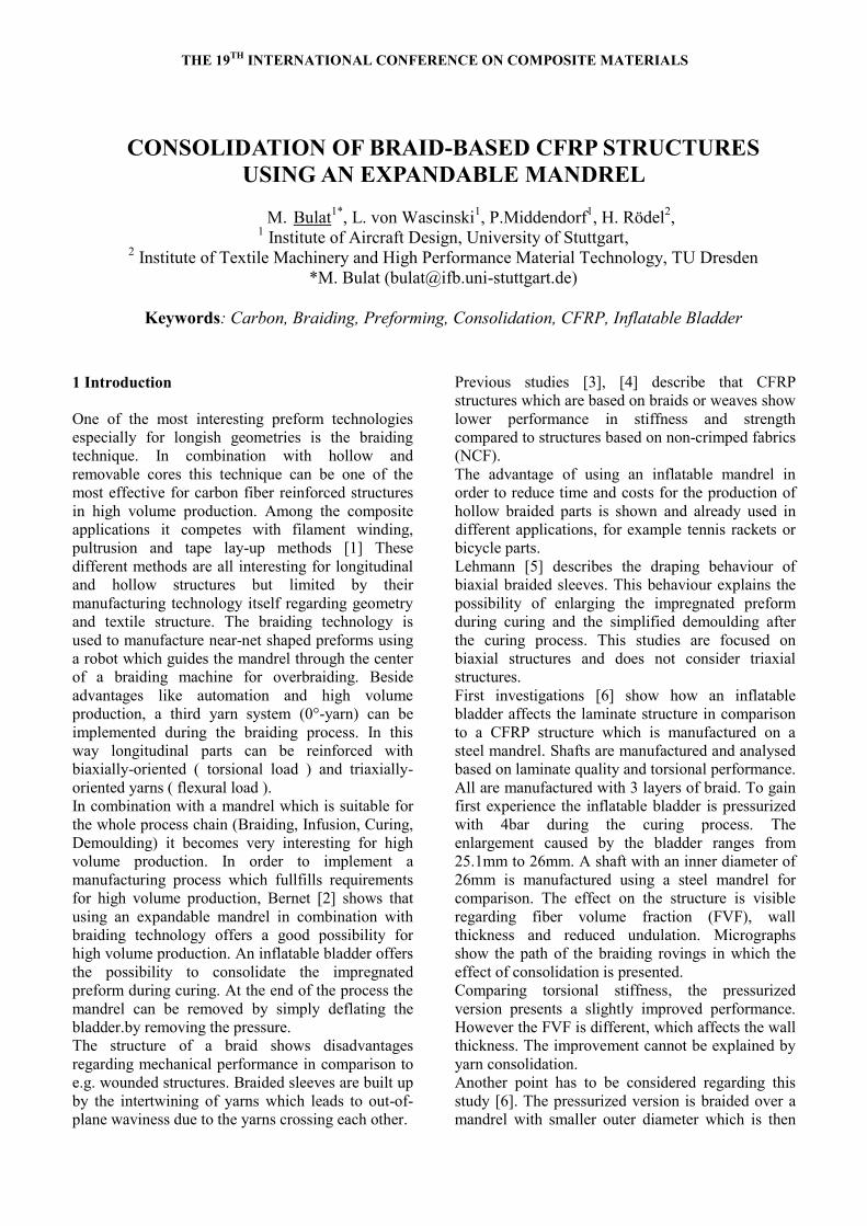
During the braiding process, the bobbins move on
the inner side of the braiding machine (Fig. 1)
crossing sinusoidal paths. By using a pair of bobbins
where each is running in the opposite direction, the
yarns are crossing each other in a repeating manner.
In that way a braided sleeve is manufactured in the
middle of the braiding machine.
The mandrel is guided by a robot through the center
of the braiding machine for overbraiding.
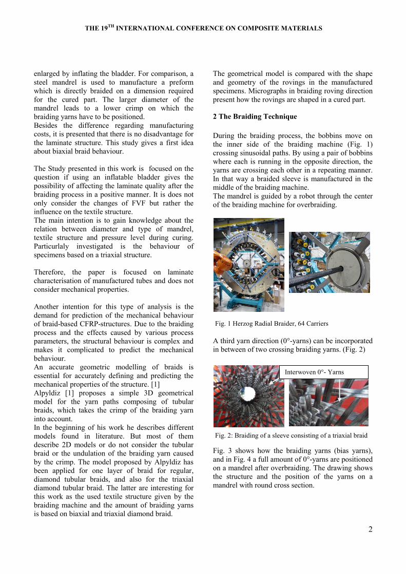
A third yarn direction (0°-yarns) can be incorporated
in between of two crossing braiding yarns. (Fig. 2)
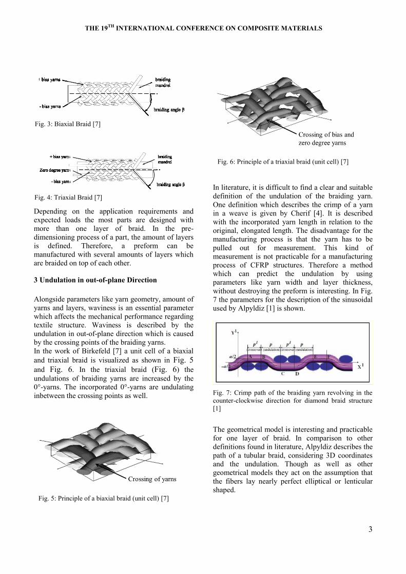
Fig. 3 shows how the braiding yarns (bias yarns),
and in Fig. 4 a full amount of 0°-yarns are positioned
on a mandrel after overbraiding. The drawing shows
the structure and the position of the yarns on a
mandrel with round cross section.
Fig. 1 Herzog Radial Braider, 64 Carriers
Interwoven 0°- Yarns
Fig. 2: Braiding of a sleeve consisting of a triaxial braid
THE 19TH
INTERNATIONAL CONFERENCE ON COMPOSITE MATERIALS
3
Depending on the application requirements and
expected loads the most parts are designed with
more than one layer of braid. In the pre-
dimensioning process of a part, the amount of layers
is defined. Therefore, a preform can be
manufactured with several amounts of layers which
are braided on top of each other.
3 Undulation in out-of-plane Direction
Alongside parameters like yarn geometry, amount of
yarns and layers, waviness is an essential parameter
which affects the mechanical performance regarding
textile structure. Waviness is described by the
undulation in out-of-plane direction which is caused
by the crossing points of the braiding yarns.
In the work of Birkefeld [7] a unit cell of a biaxial
and triaxial braid is visualized as shown in Fig. 5
and Fig. 6. In the triaxial braid (Fig. 6) the
undulations of braiding yarns are increased by the
0°-yarns. The incorporated 0°-yarns are undulating
inbetween the crossing points as well.
In literature, it is difficult to find a clear and suitable
definition of the undulation of the braiding yarn.
One definition which describes the crimp of a yarn
in a weave is given by Cherif [4]. It is described
with the incorporated yarn length in relation to the
original, elongated length. The disadvantage for the
manufacturing process is that the yarn has to be
pulled out for measurement. This kind of
measurement is not practicable for a manufacturing
process of CFRP structures. Therefore a method
which can predict the undulation by using
parameters like yarn width and layer thickness,
without destroying the preform is interesting. In Fig.
7 the parameters for the description of the sinusoidal
used by Alpyldiz [1] is shown.
Fig. 7: Crimp path of the braiding yarn revolving in the
counter-clockwise direction for diamond braid structure
[1]
The geometrical model is interesting and practicable
for one layer of braid. In comparison to other
definitions found in literature, Alpyldiz describes the
path of a tubular braid, considering 3D coordinates
and the undulation. Though as well as other
geometrical models they act on the assumption that
the fibers lay nearly perfect elliptical or lenticular
shaped.
Fig. 3: Biaxial Braid [7]
Fig. 4: Triaxial Braid [7]
Fig. 5: Principle of a biaxial braid (unit cell) [7]
Fig. 6: Principle of a triaxial braid (unit cell) [7]
THE 19TH
INTERNATIONAL CONFERENCE ON COMPOSITE MATERIALS
4
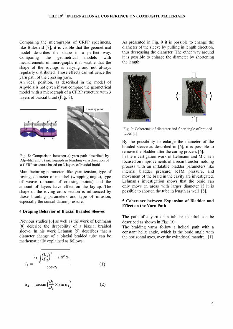
Comparing the micrographs of CRFP specimens,
like Birkefeld [7], it is visible that the geometrical
model describes the shape in a perfect way.
Comparing the geometrical models with
measurements of micrographs it is visible that the
shape of the rovings is varying and not always
regularly distributed. Those effects can influence the
yarn path of the crossing yarn.
An ideal position, as described in the model of
Alpyldiz is not given if you compare the geometrical
model with a micrograph of a CFRP structure with 3
layers of biaxial braid (Fig. 8).
Manufacturing parameters like yarn tension, type of
roving, diameter of mandrel (wrapping angle), type
of weave (amount of crossing points) and the
amount of layers have effect on the lay-up. The
shape of the roving cross section is influenced by
those braiding parameters and type of infusion,
especially the consolidation pressure.
4 Draping Behavior of Biaxial Braided Sleeves
Previous studies [6] as well as the work of Lehmann
[8] describe the drapability of a biaxial braided
sleeve. In his work Lehman [5] describes that a
diameter change of a biaxial braided tube can be
mathematically explained as follows:
√(
)
(
)
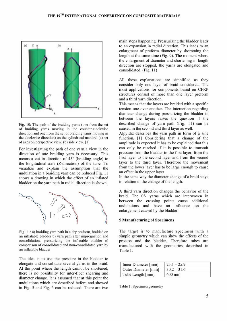
As presented in Fig. 9 it is possible to change the
diameter of the sleeve by pulling in length direction,
thus decreasing the diameter. The other way around
it is possible to enlarge the diameter by shortening
the length.
By the possibility to enlarge the diameter of the
braided sleeve as described in [6], it is possible to
remove the bladder after the curing process [6].
In the investigation work of Lehmann and Michaeli
focused on improvements of a resin transfer molding
process with an inflatable bladder parameters like
internal bladder pressure, RTM pressure, and
movement of the braid in the cavity are investigated.
Lehm ’ investigation shows that the braid can
only move in areas with larger diameter if it is
possible to shorten the tube in length as well [8].
5 Coherence between Expansion of Bladder and
Effect on the Yarn Path
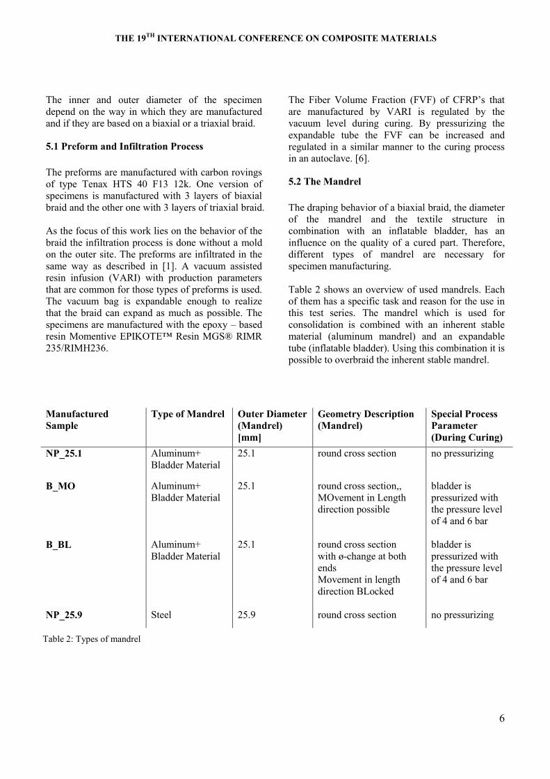
The path of a yarn on a tubular mandrel can be
described as shown in Fig. 10.
The braiding yarns follow a helical path with a
constant helix angle, which is the braid angle with
the horizontal axes, over the cylindrical mandrel. [1]
α α
Crossing yarns
Fig. 8: Comparison between a) yarn path described by
Alpyldiz and b) micrograph in braiding yarn direction of
a CFRP structure based on 3 layers of biaxial braid
Fig. 9: Coherence of diameter and fiber angle of braided
tubes [1]
THE 19TH
INTERNATIONAL CONFERENCE ON COMPOSITE MATERIALS
5
Fig. 10: The path of the braiding yarns (one from the set
of braiding yarns moving in the counter-clockwise
direction and one from the set of braiding yarns moving in
the clockwise direction) on the cylindrical mandrel (a) set
of axes on perspective view, (b) side view. [1]
For investigating the path of one yarn a view in the
direction of one braiding yarn is necessary. This
means a cut in direction of 45° (braiding angle) to
the longitudinal axis (Z-direction) of the tube. To
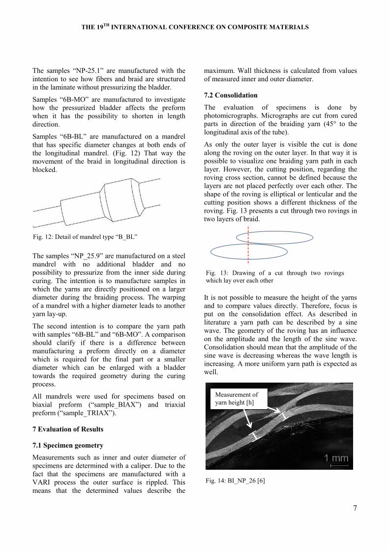
visualize and explain the assumption that the
undulation in a braiding yarn can be reduced Fig. 11
shows a drawing in which the effect of an inflated
bladder on the yarn path in radial direction is shown.
The idea is to use the pressure in the bladder to
elongate and consolidate several yarns in the braid.
At the point where the length cannot be shortened,
there is no possibility for inter-fiber shearing and
diameter change. It is assumed that at this point the
undulations which are described before and showed
in Fig. 5 and Fig. 6 can be reduced. There are two
main steps happening. Pressurizing the bladder leads
to an expansion in radial direction. This leads to an
enlargment of preform diameter by shortening the
length at the same time (Fig. 9). The moment where
the enlargment of diameter and shortening in length
direction are stopped, the yarns are elongated and
consolidated. (Fig. 11)
All these explanations are simplified as they
consider only one layer of braid considered. The
most applications for components based on CFRP
structures consist of more than one layer preform
and a third yarn direction.
This means that the layers are braided with a specific
tension one over another. The interaction regarding
diameter change during pressurizing the bladder in
between the layers raises the question if the
described change of yarn path (Fig. 11) can be
caused in the second and third layer as well.
Alpyldiz describes the yarn path in form of a sine
function. [1] Considering that a change of the
amplitude is expected it has to be explained that this
can only be reached if it is possible to transmit
pressure from the bladder to the first layer, from the
first layer to the second layer and from the second
layer to the third layer. Therefore the movement
from the lower layer has to be large enough to cause
an effect in the upper layer.
In the same way the diameter change of a braid stays
in relation to the change of the length.
A third yarn direction changes the behavior of the
braid. The 0°- yarns which are interwoven in
between the crossing points cause additional
undulations and have an influence on the
enlargement caused by the bladder.
5 Manufacturing of Specimens
The target is to manufacture specimens with a
simple geometry which can show the effects of the
process and the bladder. Therefore tubes are
manufactured with the geometries described in
Table 1.
Table 1: Specimen geometry
Inner Diameter [mm] 25.1 – 25.9
Outer Diameter [mm] 30.2 – 31.6
Tube Length [mm] 600 mm
Fig. 11: a) braiding yarn path in a dry preform, braided on
an inflatable bladder b) yarn path after impregnation and
consolidation, pressurizing the inflatable bladder c)
comparison of consolidated and non-consolidated yarn by
an inflatable bladder
P
THE 19TH
INTERNATIONAL CONFERENCE ON COMPOSITE MATERIALS
6
The inner and outer diameter of the specimen
depend on the way in which they are manufactured
and if they are based on a biaxial or a triaxial braid.
5.1 Preform and Infiltration Process
The preforms are manufactured with carbon rovings
of type Tenax HTS 40 F13 12k. One version of
specimens is manufactured with 3 layers of biaxial
braid and the other one with 3 layers of triaxial braid.
As the focus of this work lies on the behavior of the
braid the infiltration process is done without a mold
on the outer site. The preforms are infiltrated in the
same way as described in [1]. A vacuum assisted
resin infusion (VARI) with production parameters
that are common for those types of preforms is used.
The vacuum bag is expandable enough to realize
that the braid can expand as much as possible. The
specimens are manufactured with the epoxy – based
e Mome t ve EPIKOTE™ Re MGS® RIMR
235/RIMH236.
The F be Volume F t o (FVF) of CFRP’ th t
are manufactured by VARI is regulated by the
vacuum level during curing. By pressurizing the
expandable tube the FVF can be increased and
regulated in a similar manner to the curing process
in an autoclave. [6].
5.2 The Mandrel
The draping behavior of a biaxial braid, the diameter
of the mandrel and the textile structure in
combination with an inflatable bladder, has an
influence on the quality of a cured part. Therefore,
different types of mandrel are necessary for
specimen manufacturing.
Table 2 shows an overview of used mandrels. Each
of them has a specific task and reason for the use in
this test series. The mandrel which is used for
consolidation is combined with an inherent stable
material (aluminum mandrel) and an expandable
tube (inflatable bladder). Using this combination it is
possible to overbraid the inherent stable mandrel.
Manufactured
Sample
Type of Mandrel Outer Diameter
(Mandrel)
[mm]
Geometry Description
(Mandrel)
Special Process
Parameter
(During Curing)
NP_25.1 Aluminum+
Bladder Material
25.1 round cross section no pressurizing
B_MO Aluminum+
Bladder Material
25.1 round cross section,,
MOvement in Length
direction possible
bladder is
pressurized with
the pressure level
of 4 and 6 bar
B_BL Aluminum+
Bladder Material
25.1 round cross section
with ø-change at both
ends
Movement in length
direction BLocked
bladder is
pressurized with
the pressure level
of 4 and 6 bar
NP_25.9 Steel 25.9 round cross section no pressurizing
Table 2: Types of mandrel
THE 19TH
INTERNATIONAL CONFERENCE ON COMPOSITE MATERIALS
7
The mple “NP-25.1” e m uf tu ed w th the
intention to see how fibers and braid are structured
in the laminate without pressurizing the bladder.
S mple “6B-MO” e m uf tu ed to investigate
how the pressurized bladder affects the preform
when it has the possibility to shorten in length
direction.
S mple “6B-BL” e m uf tu ed o m d el
that has specific diameter changes at both ends of
the longitudinal mandrel. (Fig. 12) That way the
movement of the braid in longitudinal direction is
blocked.
The mple “NP_25.9” e m uf tu ed o teel
mandrel with no additional bladder and no
possibility to pressurize from the inner side during
curing. The intention is to manufacture samples in
which the yarns are directly positioned on a larger
diameter during the braiding process. The warping
of a mandrel with a higher diameter leads to another
yarn lay-up.
The second intention is to compare the yarn path
with mple “6B-BL” d “6B-MO”. A omp o
should clarify if there is a difference between
manufacturing a preform directly on a diameter
which is required for the final part or a smaller
diameter which can be enlarged with a bladder
towards the required geometry during the curing
process.
All mandrels were used for specimens based on
biaxial p efo m (“ mple_BIAX”) d t x l
preform (“ mple_TRIAX”).
7 Evaluation of Results
7.1 Specimen geometry
Measurements such as inner and outer diameter of
specimens are determined with a caliper. Due to the
fact that the specimens are manufactured with a
VARI process the outer surface is rippled. This
means that the determined values describe the
maximum. Wall thickness is calculated from values
of measured inner and outer diameter.
7.2 Consolidation
The evaluation of specimens is done by
photomicrographs. Micrographs are cut from cured
parts in direction of the braiding yarn (45° to the
longitudinal axis of the tube).
As only the outer layer is visible the cut is done
along the roving on the outer layer. In that way it is
possible to visualize one braiding yarn path in each
layer. However, the cutting position, regarding the
roving cross section, cannot be defined because the
layers are not placed perfectly over each other. The
shape of the roving is elliptical or lenticular and the
cutting position shows a different thickness of the
roving. Fig. 13 presents a cut through two rovings in
two layers of braid.
It is not possible to measure the height of the yarns
and to compare values directly. Therefore, focus is
put on the consolidation effect. As described in
literature a yarn path can be described by a sine
wave. The geometry of the roving has an influence
on the amplitude and the length of the sine wave.
Consolidation should mean that the amplitude of the
sine wave is decreasing whereas the wave length is
increasing. A more uniform yarn path is expected as
well.
Fig. 13: Drawing of a cut through two rovings
which lay over each other
Measurement of
yarn height [h]
Fig. 14: BI_NP_26 [6]
Fig. 12: Det l of m d el type “B_BL”
THE 19TH
INTERNATIONAL CONFERENCE ON COMPOSITE MATERIALS
8
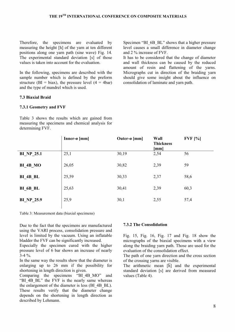
Therefore, the specimens are evaluated by
measuring the height [h] of the yarn at ten different
positions along one yarn path (sine wave) Fig. 14.
The experimental standard deviation [s] of those
values is taken into account for the evaluation.
In the following, specimens are described with the
sample number which is defined by the preform
structure (BI = biax), the pressure level (4 = 4bar)
and the type of mandrel which is used.
7.3 Biaxial Braid
7.3.1 Geometry and FVF
Table 3 shows the results which are gained from
measuring the specimens and chemical analysis for
determining FVF.
Table 3: Measurement data (biaxial specimens)
Due to the fact that the specimens are manufactured
using the VARI process, consolidation pressure and
level is limited by the vacuum. Using an inflatable
bladder the FVF can be significantly increased.
Especially the specimen cured with the higher
pressure level of 6 bar shows an increase of nearly
3-4 %.
In the same way the results show that the diameter is
enlarging up to 26 mm if the possibility for
shortening in length direction is given.
Comparing the specimens “BI_4B_MO” d
“BI_4B_BL” the FVF is the nearly same whereas
the enlargement of the diameter is less (BI_4B_BL).
These results verify that the diameter change
depends on the shortening in length direction as
described by Lehmann.
Spe me “BI_6B_BL” shows that a higher pressure
level causes a small difference in diameter change
and 2 % increase of FVF.
It has to be considered that the change of diameter
and wall thickness can be caused by the reduced
amount of resin and flattening of the yarns.
Micrographs cut in direction of the braiding yarn
should give some insight about the influence on
consolidation of laminate and yarn path.
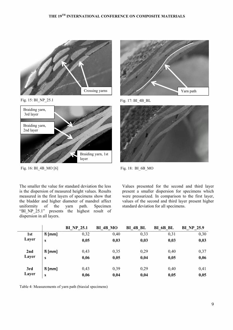
7.3.2 The Consolidation
Fig. 15, Fig. 16, Fig. 17 and Fig. 18 show the
micrographs of the biaxial specimens with a view
along the braiding yarn path. Those are used for the
evaluation of the consolidation effect.
The path of one yarn direction and the cross section
of the crossing yarns are visible.
The thmet me h d the expe me t l
standard deviation [s] are derived from measured
values (Table 4).
Inner-ø [mm] Outer-ø [mm] Wall
Thickness
[mm]
FVF [%]
BI_NP_25.1 25,1 30,19 2,54 56
BI_4B_MO 26,05 30,82 2,39 59
BI_4B_BL 25,59 30,33 2,37 58,6
BI_6B_BL 25,63 30,41 2,39 60,3
BI_NP_25.9 25,9 30,1 2,55 57,4
THE 19TH
INTERNATIONAL CONFERENCE ON COMPOSITE MATERIALS
9
The smaller the value for standard deviation the less
is the dispersion of measured height values. Results
measured in the first layers of specimens show that
the bladder and higher diameter of mandrel affect
uniformity of the yarn path. Specimen
“BI_NP_25.1” p e e t the h ghe t e ult of
dispersion in all layers.
Values presented for the second and third layer
present a smaller dispersion for specimens which
were pressurized. In comparison to the first layer,
values of the second and third layer present higher
standard deviation for all specimens.
Table 4: Measurements of yarn path (biaxial specimens)
BI_NP_25.1 BI_4B_MO BI_4B_BL BI_6B_BL BI_NP_25.9
1st
Layer
0,32 0,40 0,33 0,31 0,30
s 0,05 0,03 0,03 0,03 0,03
2nd
Layer
0,43 0,35 0,29 0,40 0,37
s 0,06 0,05 0,04 0,05 0,06
3rd
Layer
0,43 0,39 0,29 0,40 0,41
s 0,06 0,04 0,04 0,05 0,05
Fig. 16: BI_4B_MO [6]
Braiding yarn, 1st
layer
Braiding yarn,
3rd layer
Braiding yarn,
2nd layer
Fig. 15: BI_NP_25.1
Crossing yarns Yarn path
Fig. 17: BI_4B_BL
Fig. 18: BI_6B_MO
THE 19TH
INTERNATIONAL CONFERENCE ON COMPOSITE MATERIALS
10
7.4 Triaxial Braid
Results gained by the biaxial preforms show the
difference of using 4 bar and 6 bar pressure level
during curing. The best result regarding FVF and
consolidation can be reached with 6 bar (Table 3).
Therefore, the pressurized version of triaxial
specimens (TR) is just cured with 6 bar and there are
no specimens manufactured with the pressure level
of 4 bar.
7.4.1 Geometry and FVF
Results gained are presented in Table 5. Similar to
biaxial specimens it is visible that the use of
inflatable bladder during curing leads to a higher
FVF. It is assumed that the FVF is higher in
comparison to the biaxial specimens as there are
more rovings (0°-yarns) incorporated in the braid.
The compa o of the pe me “TR_NP_25.1” d
“TR_6B_MO” hows that pressurizing the bladder
leads to a higher enlargement of diameter but not as
much as if a biaxial structure is pressurized. This
leads to the assumption that the draping behavior, as
described by Lehmann for biaxial braids [8], is
influenced by the incorporated 0°-yarns.
Comparing the specimens of triaxial structure,
“TR_6B_BL” d b x l t u tu e “BI_6B_BL”, t
is presented that the enlargement of the triaxial
structure is larger. It is assumed that the higher
enlargement is only caused by the flattening of the
0°-yarns.
The specimens TR_6B_MO are compared with
TR_6B_BL. The enlargement of the inner diameter
is more or less the same. The difference is minimal.
This effect verifies the assumption that the
enlargement of diameter is not caused by shortening
the length but rather by flattening the 0°-yarns.
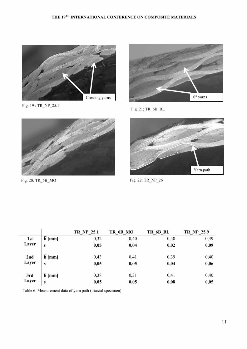
7.4.2 Consolidation
Fig. 19, Fig. 20, Fig. 21 and Fig. 22 present the
micrographs. Due to 0°-yarns, the yarn path shows
higher amplitude in comparison to the yarn path of
the of the biaxial specimen.
Results of the measurements, which are done in the
same way as for the biaxial specimens, are presented
in Table 6.
Conspicuous are the results of specimen
“TR_NP_25.1” whe e the e ult ll l ye
present the same standard deviation. The specimens
“TR_6B_MO” d “TR_6B_BL” present a lower
dispersion of values in the first layer in comparison
to the second and third one.
E pe lly pe me “TR_6B_BL” how le
uniform yarn path in the third layer.
Inner-ø [mm] Outer-ø [mm] Wall Thickness
[mm]
FVF [%]
TR_NP_25,1 25,1 31,18 3,03 56,6
TR_6B_MO 25,88 31,52 2,82 63,7
TR_6B_BL 25,83 31,59 2,88 63,6
TR_NP_25,9 25,95 31,62 2,84 56,4
Table 5 Measurement data (triaxial braid)
THE 19TH
INTERNATIONAL CONFERENCE ON COMPOSITE MATERIALS
11
TR_NP_25.1 TR_6B_MO TR_6B_BL TR_NP_25.9
1st
Layer
0,32 0,40 0,40 0,39
s 0,05 0,04 0,02 0,09
2nd
Layer
0,43 0,41 0,39 0,40
s 0,05 0,05 0,04 0,06
3rd
Layer
0,38 0,31 0,41 0,40
s 0,05 0,05 0,08 0,05
Table 6: Measurement data of yarn path (triaxial specimen)
Fig. 20: TR_6B_MO
Crossing yarns 0° yarns
Fig. 22: TR_NP_26
Yarn path
Fig. 19 : TR_NP_25.1 Fig. 21: TR_6B_BL
THE 19TH
INTERNATIONAL CONFERENCE ON COMPOSITE MATERIALS
12
8. Conclusion and Outlook
Measurements of the tube and analysis of
micrograph give an idea about the behavior and
effects of an inflatable bladder on the structure in the
laminate. The results show that the behavior is
combined by the change of FVF, consolidation of
yarns and draping behavior of the textile structure.
The effect on the FVF by using an inflatable bladder
is verified for 4 and 6 bar pressure level. By using
different types of mandrel the description of Lehman
for the behavior of biaxial braided sleeves is
verified. Diameter enlargement is depending on the
shortening of the preform in length direction.
The same behavior cannot be shown for the
specimens based on triaxial structures. The 0°-yarns
influence the draping behavior. There is no visible
difference in the diameter change when comparing
specimens where the preform can shorten in length
direction with those where the shortening is not
possible. It is assumed that the enlargement of
diameter for the triaxial specimens can be explained
by the consolidation of the 0°-yarns in the crossing
points.
The exact influence on the consolidation of the 0°-
yarns is not considered, but will be done in future
work.
The evaluation of micrographs presents that yarn
measurements cannot be measured and compared
directly. Therefore, the uniformity of yarn paths is
measured. The interpretation of results gives an idea
about how the uniformity of the yarn path is affected
by the bladder. Especially the first layer of all
pressurized versions (biaxial and triaxial) is
consolidated by the bladder. Only the results of the
biaxial specimens (BI_6B_BL, BI_4B_BL,
BI_4B_MO) present an influence on the second and
third layer.
It can be said that the shape and path of the bias yarn
which are consolidated by the bladder look more
like the geometrical model presented by Alpyldiz.
Further studies are planned in which the effect on
mechanical properties is investigated. By using an
outer mold and knowledge gained until now,
specimens based on biaxial and triaxial braids will
be manufactured. Further work is planned to clarify
the question of how the effects described in this
work affect the mechanical performance.
References
[1] T. Alpyldiz, "3D geometrical modelling of
tubular braids," Textile Research Journal, p.
82(5) 443–453, 2011.
[2] B. N., B. P.-E. and M. J.-A., "Cost-Effective
Manufacturing of hollow composite strucutres by
bladder inflation moulding," in ICCM-12, Paris,
1999.
[3] M. Bulat and O. Rüger, "Untersuchung des
Einflusses der Fadenspannungn beim Flechten
auf Faserschädigung und Bauteilkennwerte,"
Stuttgart, 2007.
[4] C. Cherif, Textile Werkstoffe fü den Leichtbau,
Dresden: Springer, 2011.
[5] U. Lehmann, Production of Hollow Composite
Parts with Inflatable Bladders in Liquid
Composite Moulding, Mainz: Verlag Mainz,
1999.
[6] M. Bulat, R. Kehrle, K. Drechsler and W.
Bommes, "Effects of pressurized cores on the
properties of braided CFRP Structures," in
SEICO, Paris, 2012.
[7] K. Birkefeld, M. Röder, T. von Reden, M. Bulat
and K. Drechsler, "Characterization of biaxial
and triaxial braids: Fiber Architecture and
mechanical properties," Appl. Composites
Material, Vols. 259-273 (2012), 2012.
[8] U. Lehmann and W. Michaeli, "Improved
Processing of Resin Transfer Molding for the
Production of Hollow Parts with Inflatable
Bladders," in 42nd International SAMPE
Symposium, Anaheim, USA, 1997.


![Improvement of Interfacial Shear Strength Using ...confsys.encs.concordia.ca/ICCM19/AllPapers/FinalVersion/RUT80577.pdf · modified by introducing nano, ... the IFSS [15] and, based](https://img.pdfslide.net/doc/110x75/5abd66f07f8b9a8e3f8bba70/improvement-of-interfacial-shear-strength-using-by-introducing-nano-the.jpg)