Embed Size (px)
Citation preview

SAFETY CONSIDERATIONSDue to system pressure, moving parts and electrical components,installation and servicing of air conditioning equipment can behazardous. Only qualified, trained, service personnel shouldinstall, repair, maintain or service this equipment.‘YORK Model DCE and DCG units are single package airconditioners designed for outdoor installation on a rooftop or aslab and is manufactured under ISO 9002 Quality SystemCertification. The DCE models are cooling only and can beequipped with factory installed electric heaters for cooling /heating applications. The DCG models are gas-fired centralheating furnaces with cooling.The units are completely assembled on rigid, permanently attachedbase rails. All piping, refrigerant charge, and electrical wiring is factoryinstalled and tested. All units require electric power, duct connectionsand fixed outdoor air intake damper (units without economizer ormotorized damper option only) at the point of installation.The DCG units additionally require gas connection, installation of thecombustion air inlet hood and the flue gas outlet hoods at the point ofinstallation. The gas-fired heaters have aluminized-steel tubular heatexchangers and spark ignition with proven pilot.Supplemental electric heaters for DCE units have nickel-chromeelements and utilize single point power connections.The following safety precautions apply to DCG units:
INSPECTIONAs soon as a unit is received, it should be inspected forpossible damage during transit. If damage is evident, theextent of the damage should be noted on the carrier’s freightbill. A separate request for inspection by the carrier’s agentshould be made in writing. Refer to Form 50.15-NM foradditional information.
REFERENCEAdditional information on the design, installation, operation andservice of this equipment is available in the following reference forms:
• 44-320-10 - Barometric Relief Damper Accessory• 530.18-N6.1V - Propane Conversion Accessory• 530.18-N6.2V - High Altitude Accessory (Nat. Gas)• 530.18-N6.3V - High Altitude Accessory (Propane)• 530.18-n13y - Coil Guard Installation
Renewal Parts:
• Refer to the Renewal Parts Manual for complete listing ofreplacement parts on this equipment.
All forms referenced in this instruction may be ordered from:Publications Distribution CenterUnitary Products GroupP.O. Box 1592, York, Pa. 17405
APPROVALSDesign certified by ETL & CGA as follows:1. For use as a central cooling only unit with or without
supplemental electric heat. (DCE models)2. For use as a forced air furnace with cooling unit. (DCG models)3. For use with natural gas or propane gas. (DCG models)4. For outdoor installation only.5. For installation on combustible material.
�� SUNLINE 2000ELECTRIC / ELECTRIC & GAS / ELECTRIC
SINGLE PACKAGE AIR CONDITIONERS(Constant Air Volume)
INSTALLATION INSTRUCTION Supersedes: 530.18-N11Y (195) 530.18-N11Y (399)
MODELS D2CE & D2CG300(8.5 EER)
035-16133
DCG MODELSHOWN
208/230/460VOLT ONLY
Installer should pay particular attention to the words: NOTE, CAUTION and WARNING. Notes are intended to clarify or makethe installation easier. Cautions are given to prevent equipment damage. Warnings are given to alert installer that personal injuryand/or equipment damage may result if installation procedure is not handled properly.
208/230/575VOLT ONLY
CAUTIONTHIS PRODUCT MUST BE INSTALLED IN STRICT COMPLIANCE WITHTHE ENCLOSED INSTALLATION INSTRUCTIONS AND ANYAPPLICABLE LOCAL, STATE, AND NATIONAL CODES INCLUDING, BUTNOT LIMITED TO, BUILDING, ELECTRICAL, AND MECHANICAL CODES.
WARNINGINCORRECT INSTALLATION MAY CREATE A CONDITIONWHERE THE OPERATION OF THE PRODUCT COULD CAUSEPERSONAL INJURY OR PROPERTY DAMAGE
FOR YOUR SAFETY
Do not store or use gasoline or other flammablevapors and liquids in the vicinity of this or anyother appliance.
FOR YOUR SAFETY
If you smell gas:1. Open windows.2. Don’t touch electrical switches; do not use any phones in the area of the gas leak.3. Extinguish any open flame.4. Immediately call your gas supplier from another location. Follow your gas supplier’s instructions.5. If you cannot reach your gas supplier, call the fire department.

General ................................................................................ 1Inspection............................................................................. 1Reference............................................................................. 1Approvals ............................................................................. 1Nomenclature....................................................................... 2
INSTALLATIONLimitations............................................................................ 3Location ............................................................................... 3Rigging and Handling .......................................................... 3Clearances........................................................................... 3Ductwork .............................................................................. 3Fixed Outdoor Air Intake Damper ........................................ 4Condensate Drain ................................................................ 4Compressors........................................................................ 4Filters ................................................................................... 4Service Access .................................................................... 4Thermostat........................................................................... 5Power and Control Wiring .................................................... 5Optional Electric Heaters (DCE Models) ............................. 5Combustion Discharge (DCG Models) ................................ 5Gas Piping (DCG Models) ................................................... 6Gas Connection (DCG Models)........................................... 6L.P. Units, Tanks and Piping (DCG Models)......................... 6Vent and Combustion Air Hoods (DCG Models) ................. 7Econ. / Mot. Damper Rain Hood Accy. (1EH0401) .............. 7Econ. / Power Rain Hood Accy. (1EH0402) ......................... 9
OPERATIONCooling System.................................................................. 15Preliminary Operation Cooling........................................... 15Cooling Sequence of Operation......................................... 15Safety Controls (Cooling)................................................... 15Electric Heating - Sequence of Operation ......................... 15Heating Anticipator Setpoints ............................................ 16Gas Heating - Sequence of Operation .............................. 16Safety Controls (Heating)................................................... 16Heat Anticipator Setpoints ................................................. 17Pre-Start Check List........................................................... 17
START-UPOperating Instructions........................................................ 17Post-Start Check List ......................................................... 17Manifold Gas Pressure Adjustment ................................... 17Pilot Checkout .................................................................... 18Burner Instructions............................................................. 18Burner Air Shutter Adjustment........................................... 18Checking Supply Air CFM.................................................. 18Adjustment of Temperature Rise........................................ 19Checking Gas Input ........................................................... 19Secure Owner’s Approval .................................................. 19
MAINTENANCE & TROUBLESHOOTINGNormal Maintenance ......................................................... 20Cleaning Flue Passages and Heating Elements ............... 20Troubleshooting.................................................................. 21Replacement Parts ............................................................ 23
TABLES No. Description Page
1 Unit Application Data .................................. 32 Gas Heat Application Data ......................... 63 Pipe Sizing.................................................. 64 Physical Data .............................................. 105 Electrical Data - Basic Units ...................... 106 Electrical Data - Units With Elec. Heat ...... 107 Four and Six Point Loads............................ 138 Supply Air Blower Performance ................. 139 Static Resistances ...................................... 14
10 Power Exhaust Performance ...................... 1411 Blower Motor and Drive Data...................... 1412 Heat Anticipator Setpoint ............................ 1613 Limit Control Setting ................................... 1714 Gas Rate - Cubic Feet Per Hour................. 19
FIGURES No. Description Page
1 Typical Rigging............................................ 32 Center of Gravity......................................... 33 Fixed Outdoor Air Damper.......................... 44 Recommended Drain Piping....................... 45 Typical Field Wiring ..................................... 56 External Supply Connection ....................... 67 Bottom Supply Connection ......................... 78 Vent and Combustion Air Hoods................. 89 Adjusting Enthalpy Setpoint........................ 9
10 Dimensions and Clearances....................... 11Dimensions and Clearances (cont’d).......... 12
11 Four and Six Point Loads............................ 1312 Gas Valve Piping......................................... 1613 Gas Valve and Controls .............................. 1714 Typical Gas Valve........................................ 1715 Proper Flame Adjustment........................... 1816 Typical Flame Appearance ......................... 1817 Belt Adjustment........................................... 1818 Pressure Drop versus Supply Air CFM ...... 1919 Typical Flue Baffle Installation .................... 20
TABLE OF CONTENTS
D 2 C G E C4N
PRODUCT NOMENCLATURE
PRODUCT GENERATION
2 = 2nd Generation
PRODUCT CATEGORY
D = Single Package Air Conditioner (Air Cooled)
PRODUCT IDENTIFIER
CG = Gas/ElectricCE = Cooling only or Electric / Electric
VOLTAGE CODE
25 = 208/230-3-6046 = 460-3-6058 = 575-3-60
NOMINAL HEATINGOUTPUT CAPACITY
300 = 25 Tons
FACTORY INSTALLEDOPTION CODE
EC = Sing. Input EconomizerDK = Diff. Input EconomizerFD = Sing. Input Economizer w/Power ExhaustCF = Diff. Input Economizer w/Power ExhaustBG = Motorized Outdoor Air Damper
2 003 0 2 5
FACTORY INSTALLEDHEAT
A = No HeatN = Natural GasE = Electric
NOMINAL COOLINGCAPACITY
GAS240 = 240 MBH320 = 320 MBH
ELECTRIC018 = 18 KW036 = 36 KW054 = 54 KW072 = 72 KW
530.18-N11Y
2 Unitary Products Group

LIMITATIONSThese units must be installed in accordance with the followingapplicable national and local safety codes:In U.S.A.:1. National Electrical Code ANSI/NFPA No. 70.2. National Fuel Gas Code Z223.1.3. Gas-Fired Central Furnace Standard ANSI Z21.47a.4. Local gas and electric utility requirements.In Canada:1. Current Canadian Electrical Code C22.1.2. Current Gas Installation Codes CAN/CGA-B149.1 and .23. Local plumbing and waste water codes.4. Other applicable local codes.Refer to the Unit Application Data Table and to the Gas Heat ApplicationData Table.After installation, units with gas heat must be adjusted to obtain atemperature rise within the range specified on the unit rating plate.If components are to be added to a unit to meet local codes, theyare to be installed at the dealer’s and/or the customer’s expense.Size of unit for proposed installation should be based on heatloss/heat gain calculation made according to the methods ofthe Air Conditioning Contractors of America (ACCA).This furnace is not to be used for temporary heating of buildingsor structures under construction.
LOCATIONUse the following guidelines to select a suitable location forthese units.1. Unit is designed for outdoor installation only.2. Condenser coils must have an unlimited supply of air.
Where a choice of location is possible, position the unit oneither north or east side of building.
3. For ground level installation, use a level concrete slab witha minimum thickness of 4 inches. The length and widthshould be at least 6 inches greater than the unit base rails.Do not tie slab to the building foundation.
WARNING: Excessive exposure of this furnace to contami-nated combustion air may result in equipment dam-age or personal injury. Typical contaminates in-clude: permanent wave solutions, chlorinatedwaxes and cleaners, chlorine based swimmingpool chemicals, water softening chemicals, carbontetrachloride, Halogen type refrigerants, cleaningsolvents (e.g. perchloroethylene), printing inks,paint removers, varnishes, hydrochloric acid, ce-ments and glues, antistatic fabric softeners forclothes dryers, masonry acid washing materials.
4. Roof structures must be able to support the weight of theunit and its options and/or accessories. Unit must be in-stalled on a solid level roof curb or appropriate angle ironframe.
CAUTION: If a unit is to be installed on a roof curb or specialframe, gasketing must be applied to all surfacesthat come in contact with the unit underside.
5. Maintain level tolerance to 1/2" maximum across the entirelength or width of the unit.
RIGGING AND HANDLINGExercise care when moving the unit. Do not remove anypackaging until the unit is near the place of installation. Rig theunit by attaching chain or cable slings to the round lifting holesprovided in the base rails. Spreaders, whose length exceedsthe largest dimension across the unit, MUST be used acrossthe top of the unit.Units may also be moved or lifted with a forklift, from the frontor rear only, providing that an accessory skid is used.LENGTH OF FORKS MUST BE A MINIMUM OF 90".
CAUTION: On gas heating units, an adhesive backed label isprovided over the outside of the combustion air inletopening to prevent moisture from entering the unitwhich could cause damage to electr icalcomponents. Allow this closure label to remain inplace until the combustion air hood is to beinstalled.
CLEARANCESAll units require certain clearances for proper operation andservice. Installer must make provisions for adequate combustionand ventilation air in accordance with Section 5.3, Air forCombustion and Ventilation of the National Fuel Gas Code, ANSIZ223.1 (in U.S.A.) or Sections 7.2, 7.3 or 7.4 of Gas InstallationCodes CAN/CGA-B149.1 and .2 (in Canada) and/or applicableprovisions of the local building codes. Refer to Dimensions andClearances table for the clearances required for combustibleconstruction, servicing, and proper unit operation.WARNING: Do not permit overhanging structures or shrubs to
obstruct outdoor air discharge outlet, combustionair inlet or vent outlets.
INSTALLATION
Voltage Variation, Min. / Max.1
208/230-3-60 187 / 253460-3-60 414 / 506575-3-60 518 / 630
Supply Air CFM, Min. / Max. 8,000 / 12,000Wet Bulb Temperature (°F) of Air on Evaporator Coil, Min. / Max.
57 / 72
Dry Bulb Temperature (°F) of Air on Condenser Coil, Min.2 / Max.
25 / 120
1Utilization range “A” in accordance with ARI Standard 110.2A low ambient accessory is available for applications down to 0°F.
TABLE 1 - UNIT APPLICATION DATA
FIG. 1 - TYPICAL RIGGING
136-1/4"
45
FIG. 2 - CENTER OF GRAVITY
530.18-N11Y
Unitary Products Group 3

DUCTWORKDuctwork should be designed and sized according to themethods in Manual Q of the Air Conditioning Contractors ofAmerica (ACCA).A closed return duct system shall be used. This shall notpreclude use of economizers or outdoor fresh air intake. Thesupply and return air duct connections at the unit should bemade with flexible joints to minimize noise.The supply and return air duct systems should be designed forthe CFM and static requirements of the job. They should NOTbe sized to match the dimensions of the duct connections onthe unit.CAUTION: When fastening ductwork to side duct flanges on
unit, insert screws through duct flanges only. DONOT insert screws through casing.Outdoor ductwork must be insulated andwaterproofed.
Refer to the Dimensions and Clearances figure for informationconcerning side and bottom supply and return air duct openings.
FIXED OUTDOOR AIR INTAKE DAMPER
This damper is shipped inside the return air compartment on unitsthat are not provided with an economizer or a motorized damperoption. It is completely assembled and ready for installation. Adamper baffle inside of the hood is adjustable to provide variableamounts of outdoor air intake.
Gasketing and mounting screws are provided in a parts bagattached to the hood assembly. Apply gasketing to the threeflange surfaces on the hood prior to installing the hood. Extendgasketing 1/4" beyond the top and bottom of the two sideflanges to insure adequate sealing.
Adjusting the damper to the desired air flow may be done beforemounting the hood into position or (after installation) byremoving the front hood panel or the screen on the bottom ofthe hood. Damper baffle in position 1 will allow approximately10% recirculated air flow, position 2 approximately 15% and, toallow approximately 25%, remove the damper baffle.
On units with bottom return air applications, install the damperassembly over the opening in the side return air access panel.Remove and discard the opening cover and the covering overthe hood mounting holes (used for shipping) before installing.Secure with the screws provided.
On units with side return air applications, install the damperassembly on the return air ductwork as close to the unit aspossible. Cut an opening 16" high by 18" wide in the ductworkto accommodate the damper. Using the holes in the hoodflanges as a template, drill 9/64" dia. (#26 drill) holes into theductwork and secure with the screws provided.
CAUTION: If outdoor air intake will not be required on unitswith bottom return air applications, the damperassembly should still be mounted on the side returnair access panel, per the instructions above, toinsure moisture is not drawn into the unit duringoperation. The covering over the mounting holesonly need be removed. Do not remove the openingcover.
CONDENSATE DRAINPlumbing must conform to local codes. Use a sealingcompound on male pipe threads. Install a condensate drain linefrom the 1" NPT female connection on the unit to an open drain.
NOTE: The condensate drain line MUST be trapped to provideproper drainage.
COMPRESSORSUnits are shipped with compressor mountings factory-adjustedand ready for operation.CAUTION: Do Not loosen compressor mounting bolts.
FILTERS2" filters are supplied with each unit. Filters must always be installedahead of the evaporator coil and must be kept clean or replacedwith same size and type. Dirty filters will reduce the capacity of theunit and will result in frosted coils or safety shutdown. Minimum filterarea and required sizes are shown in the Physical Data Table.
SERVICE ACCESSAccess to all serviceable components is provided by thefollowing removable panels:
• Compressor compartment• Electric Heat compartment - DCE models• Gas Heat compartment (Two panels) - DCG models• Side Supply & Return Air compartments (Two panels)• Blower compartment (Three panels)• Main control box• Filter compartment• Outdoor Air compartment (Two panels)Refer to the Dimensions and Clearances figure for location of theseaccess panels.CAUTION: Make sure that all screws and panel latches are
replaced and properly positioned on the unit tomaintain an air-tight seal.
FIG. 3 - FIXED OUTDOOR AIR DAMPER
FIG. 4 - RECOMMENDED DRAIN PIPING
It is recommended that, in Canada, the outlet duct on gasheating units be provided with a removable access panel. It isrecommended that this opening be accessible when the unitis installed in service, and of a size such that smoke orreflected light may be observed inside the casing to indicatethe presence of leaks in the heat exchanger. The cover shouldbe attached in a manner adequate to prevent leakage.
530.18-N11Y
4 Unitary Products Group

FIG. 5 - TYPICAL FIELD WIRING
Wire Size1 AWG. Gauge
22 20 19 18 16
25 40 50 65 100
Maximum Wire Length2 Feet
Notes:
1. Solid, Class II copper wire
CONTROL WIRE SIZES
530.18-N11Y
Unitary Products Group 5

THERMOSTATThe room thermostat should be located on an inside wallapproximately 56" above the floor where it will not be subjectto drafts, sun exposure or heat from electrical fixtures orappliances. Follow manufacturer’s instructions enclosed withthermostat for general installation procedure. Seven colorcoded insulated wires should be used to connect thermostat tounit.
POWER AND CONTROL WIRINGField wiring to the unit must conform to provisions of theNational Electrical Code, ANSI / NFPA No. 70 (in U.S.A.),current Canadian Electrical Code C22.1 (in Canada) and/orlocal ordinances. The unit must be electrically grounded inaccordance with NEC and CEC (as specified above) and/orlocal codes. Voltage tolerances which must be maintained atthe compressor terminals during starting and runningconditions are indicated on the unit Rating Plate.The internal wiring harness furnished with this unit is an integralpart of a ETL and CGA design certified unit. Field alteration tocomply with electrical codes should not be required.A fused disconnect switch should be field provided for the unit.The switch must be separate from all other circuits. Wire entryat knockout openings require conduit fittings to comply withNEC (in U.S.A.), CEC (in Canada) and/or local codes. If anyof the wire supplied with the unit must be replaced, replacementwire must be of the type shown on the wiring diagram and thesame minimum gauge as the replaced wire.Electrical line must be sized properly to carry the load. Eachunit must be wired with a separate branch circuit fed directlyfrom the meter panel and properly fused.CAUTION: When connecting electrical power and control
wiring to the unit, waterproof type connectorsMUST BE USED so that water or moisture cannotbe drawn into the unit during normal operation. Theabove waterproofing conditions will also applywhen installing a field-supplied disconnect switch.
Refer to Typical Field Wiring Figure for typical field wiring and tothe appropriate unit wiring diagram for control circuit and powerwiring information.
OPTIONAL ELECTRIC HEATERS (DCE Models)
The factory installed heaters are wired for single point powersupply. Power supply need only be brought into the single pointterminal block and thermostat wiring to the low voltage terminalblock located in the upper portion of the unit control box.
These ETL and CGA approved heaters are located within thecentral compartment of the unit with the heater elementsextending into the supply air chamber. Refer to the Dimensionand Clearances figure for access panel location.
Fuses are supplied, where required, by the factory. Some KWsizes require fuses and others do not. Refer to the UnitApplication Data Table 1 for minmum CFM limitations and toElectrical Data Table.
COMBUSTION DISCHARGE (DCG Models)The products of combustion are discharged horizontallythrough two screened (hooded) openings on the upper gasheat access panel.
GAS PIPING (DCG Models)Proper sizing of gas piping depends on the cubic feet per hourof gas flow required, specific gravity of the gas and the lengthof run. “National Fuel Gas Code” Z223.1 (in U.S.A.) or thecurrent Gas Installation Codes CAN/CGA-B149.1 and .2 (inCanada) should be followed in all cases unless superseded bylocal codes or gas utility requirements. See Pipe Sizing table.The heating value of the gas may differ with locality. The valueshould be checked with the local gas utility.
NOTE: There may be a local gas utility requirement specifyinga minimum diameter for gas piping. All units require a1 inch pipe connection at the entrance fitting.
GAS CONNECTION (DCG Models)The gas supply line can be routed through the knockoutslocated on the front of the unit or through the opening providedin the unit’s base. Typical supply piping arrangements areshown in the Supply Connection figures. All pipe, fittings, etc.are field-supplied.Two grommets are shipped in the blower compartment (in partsbag taped to the blower housing) of every unit with gas heatand should be used in the knockouts when the gas pipingenters through the front of the unit.After the gas supply piping has been installed, the bottomopening in the unit should be sealed to prevent water fromleaking into the building.Gas piping recommendations:1. A drip leg and a ground joint union must be installed in the
gas piping.2. When required by local codes, a manual shut-off valve may
have to be installed outside of the unit.3. Use wrought iron or steel pipe for all gas lines. Pipe com-
pound should be applied sparingly to male threads only.
Input Capacity (Mbh) Output Capacity (Mbh)
GasRate2
(Ft.3/Hr.)
Temp.Rise °F
AtFull Input 3
0 To2,000 Feet
AboveSea Level
2,000 To4,500 Feet
AboveSea Level1
0 To2,000 Feet
AboveSea Level
2,000 To4,500 Feet
AboveSea Level1
Max. Min. Max. Min. Max. Max. Min. Max.
300 150 270 135 240 213 279 20 50
400 200 360 180 320 281 372 30 60
NOTE: Heaters are shipped available for natural gas, but can be converted to L.P. / Propane with Kit Model No. 1NP0418.1MBH rating should be reduced at the rate of 4 percent for each 1,000 feet above 4,500 feet.2Based on maximum input and 1075 Btu/Ft3.3The air flow must be adjusted to obtain a temperature rise within the range shown.
TABLE 2 - GAS HEAT APPLICATION DATA
FIG. 6 - EXTERNAL SUPPLY CONNECTIONEXTERNAL SHUT-OFF
Length in FeetNominal Iron Pipe Size
1 in. 1-1/4 in.102030405060708090
100
520350285245215195180170160150
1,050730590500440400370350320305
Maximum capacity of pipe in cubic feet of gas per hour. (Based upon a pressure drop of 0.3inch water column and 0.6 specific gravity gas).
TABLE 3 - PIPE SIZING
530.18-N11Y
6 Unitary Products Group

WARNING: Natural gas may contain some propane. Propane,being an excellent solvent, will quickly dissolvewhite lead or most standard commercialcompounds. Therefore, a special pipe compoundmust be applied when wrought iron or steel pipe isused. Shellac base compounds such as Gaskolacor Stalastic, and compounds such as Rectorseal#5, Cyde’s or John Crane may be used.
4. All piping should be cleaned of dirt and scale by hammeringon the outside of the pipe and blowing out the loose dirt andscale. Before initial start-up, be sure that all of the gas linesexternal to the unit have been purged of air.
5. The gas supply should be a separate line and installed inaccordance with all safety codes as prescribed under“Limitations”. After the gas connections have beencompleted, open the main shut-off valve admitting normalgas pressure to the mains. Check all joints for leaks withsoap solution or other material suitable for the purpose.NEVER USE A FLAME.
6. The furnace and its individual manual shut-off valve mustbe disconnected from the gas supply piping system duringany pressure testing of that system at test pressures inexcess of 1/2 psig (3.48kPa).The furnace must be isolated from the gas supply pipingsystem by closing its individual manual shut-off valve duringany pressure testing of the gas supply piping system at testpressures equal to or less than 1/2 psig (3.48kPa).
7. A 1/8 inch NPT plugged tapping, accessible for test gageconnection, must be installed immediately upstream of thegas supply connection to the furnace.
L.P. UNITS, TANKS AND PIPING (DCG Models)
All gas heat units are shipped from the factory equipped fornatural gas use only. The unit may be converted in the field foruse with L.P./propane gas with accessory kit model number1NP0418.
All L.P./propane gas equipment must conform to the safetystandards of the National Fire Protection Association.
For satisfactory operation, L.P./propane gas pressure must be8.8 inch W.C at the unit under full load. Maintaining proper gaspressure depends on three main factors:
1. The vaporization rate which depends on (a) the tempera-ture of the liquid and (b) the “wetted surface” area of thecontainer or containers.
2. The proper pressure regulation. (Two-stage regulation isrecommended from the standpoint of both cost and effi-ciency.)
3. The pressure drop in the lines between regulators andbetween the second stage regulator and the appliance.Pipe size required will depend on the length of the pipe runand the total load of all appliances.
Complete information regarding tank sizing for vaporization,recommended regulator settings, and pipe sizing is availablefrom most regulator manufacturers and L.P./propane gassuppliers.
L.P./propane gas is an excellent solvent and special pipecompound must be used when assembling piping for this gasas it will quickly dissolve white lead or most standardcommercial compounds. Shellac base compounds such asRectorseal #5 are satisfactory for this type of gas.
Check all connections for leaks when piping is completed,using a soap solution. NEVER USE A FLAME.
FIG. 7 - BOTTOM SUPPLY CONNECTIONEXTERNAL SHUT-OFF
530.18-N11Y
Unitary Products Group 7

VENT AND COMBUSTION AIR HOODS(DCG Models)
Two vent hoods and a combustion air hood (with screens) areshipped attached to the blower housing in the blowercompartment. These hoods must be installed to assure properunit function. All hoods must be fastened to the outside of thegas heat access panel with the screws provided in the bag alsoattached to the blower housing.
The screen for the combustion air intake hood is secured to theinside of the access panel opening with four fasteners and thescrews used for mounting the hood to the panel. The top flangeof this hood slips in under the top of the access panel openingwhen installing. Refer to the Vent and Combustion Hood figure.
Each vent hood is installed by inserting the top flange of thehood into the slotted opening in the access panel and securingin place.
OPTIONAL ECONOMIZER/MOTORIZED DAMPERRAIN HOOD
The instruction for the optional economizer/motorized damperrain hood can be found in form 44-320-2. Use these instructionswhen field assembling an economizer rain hood onto a unit.The outdoor and return air dampers, the damper actuator, thedamper linkage, the outdoor and return air divider baffles, andall the control sensors are factory mounted as part of the"Factory installed" economizer option.
ENTHALPY SET POINT ADJUSTMENT
Remove the economizer access panel from the unit to checkthe following adjustments. Loosen but do not remove the twopanel latches.
CAUTION: Extreme care must be exercised in turning both thesetpoint and minimum position adjusting screws toprevent twisting them off.
1. The enthalpy set point may now be set by selecting thedesired setpoint shown in the Enthalpy figure. Adjust asfollows:
• For a single enthalpy operation, carefully turn the setpoint adjusting screw to the “A”, “B”, “C” or “D” settingcorresponding to the lettered curve.
• For a dual enthalpy operation, carefully turn the set pointadjusting screw fully clockwise past the “D” setting.
2. To check that the damper blades move smoothly withoutbinding, carefully turn the minimum position adjustingscrew fully clockwise and then energize and de-energizeterminals “R” to “G”. With terminals “R” to “G” energized,turn the minimum position screw counterclockwise until thedesired minimum position has been attained.
3. Replace the economizer access panel. Reposition the twolatches horizontally and retighten the screws.
POWER EXHAUST/BAROMETRIC RELIEF DAMPERAND RAIN HOOD OPTION
The instructions for the power exhaust/barometric reliefdamper and rain hood can be found in form 44-320-10. Theexhaust fan, all supporting brackets, angles, and the wiring arefactory installed as part of the power exhaust option.
All of the components, including the dampers, hardware, andmounting instructions are shipped in a single package externalfrom the unit. The hood must be field assembled and installed.
Power exhaust is not available as a field installed option.
VENT AIROUTLETHOODS
SLOTTEDOPENINGS IN ACCESS PANEL
COMBUSTIONAIR INTAKEHOOD
GAS HEATACCESSPANELS
FIG. 8 - VENT AND COMBUSTION AIR HOODS
530.18-N11Y
8 Unitary Products Group

FIG. 9 - ENTHALPY SETPOINT ADJUSTMENT
530.18-N11Y
Unitary Products Group 9

TABLE 4 - PHYSICAL DATA
MODELSDCE/DCG
300EVAPORATOR
BLOWERCENTRIFUGAL BLOWER (Dia. x Wd. in.) 18 x 15FAN MOTOR HP 15
EVAPORATORCOIL
ROWS DEEP 4FINS PER INCH 13.5FACE AREA (Sq. Ft.) 25.0
CONDENSERFAN
(Two Per Unit)
PROPELLER DIA. (in.) (Each) 30FAN MOTOR HP (Each) 1NOM. CFM TOTAL (Each) 7200
CONDENSERCOIL
ROWS DEEP 3FINS PER INCH 15FACE AREA (Sq. Ft.) 43.3
COMPRESSOR(Qty. Per Unit) 12.5-TON TANDEM 2
AIRFILTERS
QUANTITY PER UNIT (16" X 20" X 2") 2QUANTITY PER UNIT (16" X 25" X 2") 4QUANTITY PER UNIT (14" X 20" X 2") 3TOTAL FACE AREA (sq. ft.) 21.4
CHARGE REFRIGERANT22 (lbs./oz.)
SYSTEM NO. 1 20/8SYSTEM NO. 2 20/0
*This compressor will be energized first.
OPERATING WEIGHTS (LBS.) 25 TON
Basic Unit
DCE (Cooling only) 2730DCG(Gas /Electric)
N240 2930
N320 2970
Options
Economizer 160Economizer withPower Exhaust 245
Motorized Damper 150
ElectricHeater(DCE only)
18 KW 2536 KW 3054 KW 3572 KW 40
Accessories
Roof Curb 185Barometric Damper 45Economizer/MotorizedDamper Rain Hood 55
Economizer/Power ExhaustRain Hood 90
Wood Skid 220
SUPPLY AIR MINIMUM MAXIMUM
POWER BLOWER MOTOR CIRCUIT OVERCURRENT
SUPPLY RLA LRA HP FLA AMPACITY DEVICE (1)(ea.) (ea.) (ea.) (ea.) (AMPS) (AMPS)
D2CE300 208/230-3-60 41.4 312 1 4.2 15 38.6 139.5 175& D2CG300 460-3-60 20.0 140 1 2.1 15 19.3 68.3 80
575-3-60 16.4 108 1 2.0 15 15.4 56.1 70
MODEL NO.
COMPRESSORS
(QTY. 2)
COND. FAN
(#1 & #2)
HP RLA
TABLE 5 - ELECTRICAL DATA - BASIC UNITS
MINIMUM MAXIMUMMODEL POWER CIRCUIT OVERCURRENTD2CE SUPPLY AMPACITY DEVICE (1)
(AMPS) (AMPS)
300A25 208-3-60 E018 13.5 1 37.5 139.5 175300A25 208-3-60 E036 27.0 2 75.1 142.1 175300A25 208-3-60 E054 40.6 2 112.6 189.0 200300A25 208-3-60 E072 54.1 2 150.1 198.4 225300A25 230-3-60 E018 18.0 1 43.3 139.5 175300A25 230-3-60 E036 36.0 2 86.6 156.5 175300A25 230-3-60 E054 54.0 2 129.9 178.2 200300A25 230-3-60 E072 72.0 2 173.2 221.5 250300A46 460-3-60 E018 18.0 1 21.7 68.3 80300A46 460-3-60 E036 36.0 2 43.3 78.3 80300A46 460-3-60 E054 54.0 2 65.0 89.1 100300A46 460-3-60 E072 72.0 2 86.6 110.7 125300A58 575-3-60 E018 18.0 1 17.3 56.1 70300A58 575-3-60 E036 36.0 2 34.6 62.6 70300A58 575-3-60 E054 54.0 2 52.0 71.2 80300A58 575-3-60 E072 72.0 2 69.3 88.5 100
ELECTRIC HEATER OPTION
MODEL kW(1) STAGES AMPS
TABLE 6 - ELECTRICAL DATA - UNITS w/ELECTRIC HEAT
VOLTAGELIMITATIONS**
POWER SUPPLYVOLTAGE
MIN. MAX.208/230-3-60 187 253
460-3-60 414 506575-3-60 518 630
**Utilization Range “A” in accordance with ARI Standard 110.
NOMINAL VOLTAGE VOLTAGE KW CAP. MULTIPLIER208 208 1.00240 230 0.92480 460 0.92600 575 0.92
530.18-N11Y
10 Unitary Products Group

Cont’d.FIG. 10 - DIMENSIONS & CLEARANCES - DCE & DCG
All dimensions are in inches. They are sub-ject to change without notice. Certified di-mensions will be provided upon request.
CLEARANCESFront 36"
Back 24" (Less Economizer)49" (With Economizer)
Left Side (Filter Access) 24" (Less Economizer)36"3(With Economizer)
Right Side (Cond. Coil) 36"Below Unit1 20"
Above Unit272" With 36" Maximum Horizontal Overhang (For Condenser Air Discharge)
1Units (applicable in U.S.A. only) may be installed on combustible floors made from wood or class A, B or C roof covering material.2Units must be installed oudoors. Overhanging structures or shrubs should not obstruct condenser air discharge outlet.3If economizer is factory installed, the assembled hood kit must be removed prior to final installation. This hood is 54" long.
NOTE:DCE Models: Units and ductwork are approved for zero clearance to combus-tible materials when equipped with electric heaters.
DCG Models: A 1" clearance must be provided between any combustiblematerial and the supply air ductwork for a distance of 3 feet from the unit.
The products of combustion must not be allowed to accumulate within aconfined space and recirculate.
Locate unit so that the vent air outlet hood is at least:
• Three (3) feet above any forced air inlet located within 10 horizontal feet(excluding those integral to the unit).
• Four (4) feet below, 4 horizontal feet from, or 1 foot above any door or gravityair inlet into the building.
• Four (4) feet from electric meters, gas meters, regulators and relief equip-ment.
HOLEOPENING
SIZE(DIA.)
USED FOR
A1-1/8" KO Control
WiringFront
3/4" NPS (Fem.) Bottom
B3-5/8" KO Power
WiringFront
3" NPS (Fem.) BottomC 2-3/8" KO Gas Piping (Front)D 1-11/16" Hole Gas Piping (Bottom)*
*Opening in the bottom of the unit can be located by the slice in the insulation.
UTILITIES ENTRY DATA
RETURN AIR
SUPPLY AIR
CONDENSER AIR
OUTDOOR AIR(Economizer)
� � � � � � �� � �
� � �� � �
� � � � � � � � �� � � � � � � � � �� � � � � � � � � �
� � � � � � � � �
� � � � � � � � � � � � �� � � � �
� � �� � � � � � � � � � � � � � �� � � � �
� � � � �� � � � � � � � � � � � � � ! � � " � # $ � � � % � � � � � � � & � � � � � � � & ' ( � �! " � � # " � # � � % � � & � � � � � � � % � � � � & � � ) � � ) � � � # " * � � � % � � & �# � ) ) + , � ' ! � � � � � � � ' " � � ! � � � � � � � � � " � # -
� � � � � � � � � � � . � � � � � & � / � # � ) ' � ' � � + , � � � � " + + � # � � ' � � � � � � � � � � � � � � ) � " ( # � ' ! � � / � �� � � � � " � � + � � ' � " � #
0 1 2 0 3 1 4
5 2 0 3 6 4
7 2 0 3 7 4
5 2 8 3 6 4
8 2 8 3 6 4
� � � � � � � � � � � � �� � � � �
� � �� � � � � � � � � � � � � � �� � � � �
5 1 4
� � � � � � � �� � � �
� � � � � � �� � � � � � � � � �
� � � � � � �� � � � � � � � ! � � ' " + � 4 9 4 �
� � � � � � � : � � � 3 � � � � � � � : � � � � � � � � $� � 9 � � � � � � � � � � � � � � � ; � � � � � � � � � � � � � � � 9 . � � � � � � � � � . � � � � � � � ! � � ' " + � 4 � 4 �
� � � � � 2 � � � � �� � � � � � � � � � � � � � .� � � � � � � �
� � � � �� � � �
� � � � � � � � � � �� � � �
� � � � �� � � � � � � � � �� � � � � � � < " + " ' � , �
� � � � � � �� � � � � ) � � # # � � �� � � ) � � � ' ! " ( �
� � � � �
� � � � � � � � � � � � . � � �� � � �
� � � � � � � � � 9� � � �
1 0 4
= 4
5 2 8 3 6 4
0 0 2 0 3 1 4
1 2 8 3 6 4 1 0 2 0 3 1 4
8 8 4
8 = 4
= 2 > 3 7 4
8 = 2 0 3 6 4
= 1 2 = 3 7 4 �
0 8 ? 2 0 3 6 4 �
� � � � � � �� � �
� � �� � �
� � � � � � � � �� � � � � � � � � �� � � � � � � � � �
� � � � � � � � �
� � � � � � � � � � � � �� � � � �
� � �� � � � � � � � � � � � � � �� � � � �
� � � � �� � � � � � � � � � � � � � ! � � " � # $ � � � % � � � � � � � & � � � � � � � & ' ( � �! " � � # " � # � � % � � & � � � � � � � % � � � � & � � ) � � ) � � � # " * � � � % � � & �# � ) ) + , � ' ! � � � � � � � ' " � � ! � � � � � � � � � " � # -
� � � � � � � � � � � . � � � � �
& � / � # � ) ' � ' � � + , � � � � " + + � # � � ' � � � � � � � � � � � � � � ) � " ( # $ � � / � �' ! � � ' # � " ) " ( � � � � � � " � �+ � � ' � " � #
0 1 2 0 3 1 4
5 2 0 3 6 4
7 2 0 3 7 4
5 2 8 3 6 4
8 2 8 3 6 4
� � � � � � � � � � � � �� � � � �
� � �� � � � � � � � � � � � � � �� � � � �
5 1 4
� � � � � � � �� � � �
� � � � � � �� � � � � � � � � �
� � � � � � �� � � � � � � � ! � � ' " + � 4 9 4 �
� � � � � � � : � � � 3 � � � � � � � : � � � � � � � � $� � 9 � � � � � � � � � � � � � � � ; � � � � � � � � � � � � � � � 9 . � � � � � � � � � . � � � � � � � ! � � ' " + � 4 � 4 �
� � � � � 2 � � � � �� � � � � � � � � � � � � � .� � � � � � � �
� � � � �� � � �
� � � � � � � � � � �� � � �
� � � � �� � � � � � � � � �� � � � � � � < " + " ' � , �
� � � � � � �� � � � � ) � � # # � � �� � � ) � � � ' ! " ( �
� � � � �
� � �
� � � � � � � � � 9� � � �
1 0 4
= 4
5 2 8 3 6 4
0 0 2 0 3 1 4
1 2 8 3 6 4 1 0 2 0 3 1 4
8 8 4
8 = 4
= 2 > 3 7 4
6 ? 2 = 3 7 4
> 2 0 3 7 4
? 2 8 3 7 4
@ � � � � � � �� � � � � �. � � �
� � � � � � � �� � � � � � � � �. � � �
� � � . � � �� � � �
� � �� � � � � � �� � � � �
6 ? 2 = 3 7 4
0 0 2 0 3 7 4
� � �� � � � � �� � � � �
8 = 2 0 3 6 �
0 8 ? 2 0 3 6
= 1 2 = 3 7 �
530.18-N11Y
Unitary Products Group 11

FIG. 10 - DIMENSIONS & CLEARANCES (Cont’d.)- DCE & DCG
SUPPLYAIR
RETURN AIR
OUTDOORAIR
5-1/8"
18-5/8"
27-3/4"
29-5/8" (15 TON)39-5/8" (20 TON)
40-1/2"
OUTDOOR AIRCOMPARTMENTACCESS
FILTER ACCESS
1" NPT FEMALECOND. DRAINCONNECTION
DOT PLUG(For pressuredrop reading)
EVAPORATORSECTION
CONDENSERSECTION
GAUGE LINEACCESS
40-3/8"
5-1/2"
COMPRESSORACCESS
SUPPLY AIRACCESS
RETURN AIRACCESS
REARVIEW
DETAIL “X”
ACCESSORY SIDE SUPPLY AND RETURN AIR OPENINGS
DUCT COVERS - Units are shipped with the bottomduct openings covered. An accessory flange kit is avail-able for connecting side ducts.For bottom duct applications:1. Remove the side panels from the supply and return air compartments to gain access to the bottom supply and return air duct covers.2. Remove and discard the bottom duct covers. (Duct openings are closed with sheet metal covers except when the unit includes a power exhaust option. The covering consists of a heavy black paper composition.)3. Replace the side supply and return air compartment panels.For side duct applications;1. Replace the side panels on the supply and return air compartments with the accessory flange kit panels.2. Connect ductwork to the duct flanges on the rear of the unit.
39-5/8
������������� ���
����������� ���������������������������������
������ ��� �� ����������������������!������������������� ������ ��"��� �� ��������
��������������� ����������
#������ �������� �$�������%�&���!�����������������������
'(������� � ��������)��*��������!�
���+��� ����+���
�� ����(�(��� ��� �����������
,-(
--.'"/(0/(,-.'"1(
2(
,1.'"1(
'-.'"3(
/(
DETAIL “Y”
UNIT WITH RAIN HOODS
530.18-N11Y
12 Unitary Products Group

�
4
�
#�� �
4 POINT LOADS
FIG. 11- FOUR AND SIX POINT LOADS
�
�
�
4
#
#�� �
6 POINT LOADS
UNIT4 - POINT LOADS (LBS)
TOTAL A B C D300 3,130 615 671 962 882
NOTE: These weights are with economizer, high heat, and the largest blower motor available.
UNIT6 - POINT LOADS (LBS)
TOTAL A B C D E F300 3,130 418 438 533 628 603 510
NOTE: These weights are with economizer, high heat, and the largest blower motor available.
TABLE 7 - FOUR AND SIX POINT LOADS
TABLE 8 - SUPPLY AIR BLOWER PERFORMANCE DCE300 - BOTTOM DUCT CONNECTIONS (COOLING APPLICATIONS)
BLOWER PULLEYSPEED TURNS ESP OUTPUT INPUT ESP OUTPUT INPUT ESP OUTPUT INPUT ESP OUTPUT INPUT ESP OUTPUT INPUT
(rpm) OPEN: (iwg) (bhp) (kW) (iwg) (bhp) (kW) (iwg) (bhp) (kW) (iwg) (bhp) (kW) (iwg) (bhp) (kW)
975 6.0* 1.4 5.9 4.9 1.0 7.3 6.0 0.5 8.8 7.2 - - - - - -1005 5.0 1.6 6.2 5.1 1.2 7.7 6.3 0.7 9.2 7.6 0.1 10.9 8.9 - - -1040 4.0 1.8 6.6 5.4 1.4 8.1 6.7 0.9 9.7 8.0 0.3 11.4 9.4 - - -1070 3.0 2.0 6.9 5.7 1.6 8.5 7.0 1.1 10.2 8.3 0.6 11.9 9.8 - - -1100 2.0 2.1 7.3 6.0 1.8 8.9 7.3 1.3 10.6 8.7 0.8 12.4 10.2 0.2 14.3 11.71135 1.0 2.4 7.7 6.3 2.0 9.3 7.6 1.6 11.1 9.1 1.0 13.0 10.6 0.4 14.9 12.21165 0.0 2.6 8.0 6.6 2.2 9.7 8.0 1.8 11.6 9.5 1.3 13.5 11.0 0.7 15.5 12.7
1140 6.0 2.4 7.7 6.3 2.1 9.4 7.7 1.6 11.2 9.2 1.1 13.1 10.7 0.5 15.0 12.31180 5.0 2.7 8.2 6.7 2.3 9.9 8.1 1.9 11.8 9.7 1.4 13.7 11.2 0.8 15.8 12.91215 4.0 2.9 8.6 7.0 2.6 10.4 8.5 2.2 12.3 10.1 1.7 14.3 11.7 1.1 16.4 13.51255 3.0 3.2 9.1 7.4 2.9 11.0 9.0 2.5 12.9 10.6 2.0 15.0 12.3 1.4 17.2 14.11290 2.0 3.4 9.5 7.8 3.1 11.5 9.4 2.7 13.5 11.1 2.2 15.6 12.8 - - -1330 1.0 3.7 10.0 8.2 3.4 12.0 9.9 3.0 14.1 11.6 2.6 16.4 13.4 - - -1365 0.0 3.9 10.5 8.6 3.7 12.6 10.3 3.3 14.7 12.1 2.9 17.0 13.9 - - -
NOTES:Blower performance is based on cooling only unit, with fixed outdoor air, 2" T/A filters and a dry evaporator coil. Refer to page 14 for additional static resistances.ESP - External Static Pressure available for the supply and return air duct system. All internal unit resistances have been deducted from the total static pressure of the blower.* FACTORY SETTING
12500 CFM
STANDARD DRIVE:
ACCESSORY DRIVE:
7500 CFM 8750 CFM 10000 CFM 11250 CFM
530.18-N11Y
Unitary Products Group 13

TABLE 11 - POWER EXHAUST PERFORMANCE
TABLE 12 - BLOWER MOTOR AND DRIVE DATA
MODELSIZE DRIVE
BLOWERRANGE(RPM)
MOTOR1 ADJUSTABLE MOTOR PULLEY FIXED BLOWER PULLEY BELT(NOTCHED)
HP FRAME EFF.(%)
DESIG-NATION
OUT-SIDEDIA.(IN.)
PITCHDIA.(IN.)
BORE(IN.)
DESIG-NATION
OUTSIDEDIA.(IN.)
PITCHDIA.(IN.)
BORE(IN.)
DESIG-NATION
PITCHLENGTH
(IN.)
QTY.
25 TON
Stan-dard 975/1165
15 254T 91 1LVP58B70A 7.5 6.2-7.4 1-5/8
1B5V110 11.3 11.1 1-7/16 5VX860 86.0 1
HighSpeedAccess
1140/1365 1B5V94 9.7 9.5 1-7/16 5VX840 84.0 1
1All motors have a nominal speed of 1800 RPM, a 1.15 service factor and a solid base. They can operate to the limit of their service factor because they are located in the moving air, upstream of any heating device.
MOTORSPEED
STATIC RESISTANCE OF RETURN DUCTWORK, IWG0.2 0.3 0.4 0.5 0.6
CFM KW CFM KW CFM KW CFM KW CFM KW
HIGH* 5250 0.83 4500 0.85 4200 0.88 3750 0.93 3000 0.99
MEDIUM 4900 0.77 3900 0.79 3500 0.82 2900 0.85 - -
LOW 4400 0.72 3700 0.74 3000 0.78 - - - -
*Factory Setting Power Exhaust motor is a 3/4 HP, PSC type with sleeve bearings, a 48 frame and inherent protection.
7500 8750 10000 11250 12500ESP ESP ESP ESP ESP (IWG) (IWG) (IWG) (IWG) (IWG)
DEDUCTIONS: (SUBTRACT VALUES BELOW FROM UNIT'S AVAILABLE ESP)
ALLOWANCE FOR WET COIL: 0.10 0.10 0.10 0.10 0.10
ECONOMIZER (RETURN DUCT): 0.06 0.09 0.11 0.14 0.18
18kW ELECTRIC HEAT: 0.31 0.43 0.56 0.71 0.87
36kW ELECTRIC HEAT: 0.38 0.52 0.68 0.87 1.07
54kW ELECTRIC HEAT: 0.62 0.84 1.10 1.39 1.72
72kW ELECTRIC HEAT: 0.68 0.93 1.21 1.54 1.90
ADDITIONS: (ADD VALUES BELOW TO UNIT'S AVAILABLE ESP)
HORIZONTAL (SIDE) SUPPLY DUCT: 0.31 0.26 0.27 0.31 0.41
HORIZONTAL (SIDE) RETURN DUCT: 0.05 0.05 0.05 0.05 0.05
AIRFLOW (CFM)
DESCRIPTION
TABLE 10 - STATIC RESISTANCES*
BLOWER PULLEYSPEED TURNS ESP OUTPUT INPUT ESP OUTPUT INPUT ESP OUTPUT INPUT ESP OUTPUT INPUT ESP OUTPUT INPUT
(rpm) OPEN: (iwg) (bhp) (kW) (iwg) (bhp) (kW) (iwg) (bhp) (kW) (iwg) (bhp) (kW) (iwg) (bhp) (kW)
975 6.0 1.2 5.9 4.9 0.5 7.3 6.0 - - - - - - - - -1005 5.0 1.4 6.2 5.1 0.7 7.7 6.3 - - - - - - - - -1040 4.0 1.6 6.6 5.4 0.9 8.1 6.7 0.2 9.7 8.0 - - - - - -1070 3.0 1.8 6.9 5.7 1.1 8.5 7.0 0.4 10.2 8.3 - - - - - -1100 2.0 2.0 7.3 6.0 1.3 8.9 7.3 0.6 10.6 8.7 - - - - - -1135 1.0 2.2 7.7 6.3 1.6 9.3 7.6 0.8 11.1 9.1 - - - - - -1165 0.0 2.4 8.0 6.6 1.8 9.7 8.0 1.0 11.6 9.5 0.2 13.5 11.0 - - -
1140 6.0 2.2 7.7 6.3 1.6 9.4 7.7 0.9 11.2 9.2 - - - - - -1180 5.0 2.5 8.2 6.7 1.9 9.9 8.1 1.2 11.8 9.7 0.3 13.7 11.2 - - -1215 4.0 2.7 8.6 7.0 2.1 10.4 8.5 1.4 12.3 10.1 0.6 14.3 11.7 - - -1255 3.0 3.0 9.1 7.4 2.4 11.0 9.0 1.7 12.9 10.6 0.9 15.0 12.3 - - -1290 2.0 3.2 9.5 7.8 2.7 11.5 9.4 2.0 13.5 11.1 1.2 15.6 12.8 - - -1330 1.0 3.5 10.0 8.2 3.0 12.0 9.9 2.3 14.1 11.6 1.5 16.4 13.4 - - -1365 0.0 3.7 10.5 8.6 3.2 12.6 10.3 2.6 14.7 12.1 1.8 17.0 13.9 - - -
NOTES:Blower performance is based on cooling only unit, with fixed outdoor air, 2" T/A filters and a dry evaporator coil. Refer to page 14 for additional static resistances.ESP - External Static Pressure available for the supply and return air duct system. All internal unit resistances have been deducted from the total static pressure of the blower.* FACTORY SETTING
STANDARD DRIVE:
ACCESSORY DRIVE:
7500 CFM 8750 CFM 10000 CFM 11250 CFM 12500 CFM
TABLE 9 - SUPPLY AIR BLOWER PERFORMANCE DCG300-BOTTOM DUCT CONNECTIONS(COOLING APPLICATIONS)530.18-N11Y
14 Unitary Products Group

COOLING SYSTEMThe cooling section is a complete factory package utilizing anair-cooled condenser. The system is factory-charged withRefrigerant-22.The compressors are hermetically sealed, internally sprungand base-mounted with rubber-insulated hold-down bolts.Compressors have inherent (internal) protection. If there is anabnormal temperature rise in a compressor, the protector willopen to shut down the compressor.
PRELIMINARY OPERATION COOLINGAfter the initial installation, the compressors should be giventhree false starts (energized just long enough to make a fewrevolutions) with 5-7 minutes delay between each start, beforebeing put into full time service.COOLING SEQUENCE OF OPERATIONNO OUTDOOR AIR OPTIONS - When the room thermostatcalls for “first-stage” cooling, the low voltage control circuit from“R” to “G” and “Y1" is completed to energize compressors #1/2(50% capacity), condenser fan motor #1, and the supply airblower motor (if the fan switch on the room thermostat is set inthe ”AUTO" position).When the thermostat calls for “second-stage” cooling, the lowvoltage control circuit from “R” to “Y2" is completed to energizecompressor #3/4.After the thermostat is satisfied and opens, all components willstop simultaneously. The blower motor will continue to operateif the fan switch on the room thermostat is set in the “ON”position.ECONOMIZER WITH SINGLE ENTHALPY SENSOR - Whenthe room thermostat calls for “first-stage” cooling, the lowvoltage control circuit from “R” to “G” and “Y1" is completed.The ”R" to “G” circuit energizes the blower motor (if the fanswitch on the room thermostat is set in the “AUTO” position)and drives the economizer dampers from fully closed to theirminimum position. If the enthalpy of the outdoor air is below thesetpoint of the enthalpy controller (previously determined), “Y1"energizes the economizer. The dampers will modulate tomaintain a constant supply air temperature as monitored by thedischarge air sensor. If the outdoor air enthalpy is above thesetpoint, ”Y1" energizes compressors #1/2, and condenser fanmotor #1.When the thermostat calls for “second-stage” cooling, the lowvoltage control circuit from “R” to “Y2" is completed. If theenthalpy of the outdoor air is below the setpoint of the enthalpycontroller (i.e. first stage has energized the economizer), ”Y2"will energize compressors #1/2. If the outdoor air is above thesetpoint, “Y2" will energize compressor #3/4.After the thermostat is satisfied and opens, all components willstop simultaneously. The blower motor will continue to operateif the fan switch on the room thermostat is set in the “ON”position.ECONOMIZER WITH DUAL ENTHALPY SENSORS - Theoperation with the dual enthalpy sensors is identical to thesingle sensor except that a second enthalpy sensor is mountedin the return air. This return air sensor allows the economizerto choose between outdoor air and return air, whichever hasthe lowest enthalpy value, to provide maximum operatingefficiency.ECONOMIZER (SINGLE OR DUAL) WITH POWEREXHAUST - This system operates as specified above with one
addition. The power exhaust motor is energized whenever theeconomizer is chosen by the enthalpy sensor for first stagecooling, “Y1". As always, the ”R" to “G” connection providesminimum position but does not provide power exhaustoperation.MOTORIZED OUTDOOR AIR DAMPERS - This systemoperation is the same as the units with no outdoor air optionswith one exception. When the “R” to “G” circuit is complete, themotorized damper drives open to a position set by the dampermotor adjustment. When the “R” to “G” circuit is opened, thedamper spring returns fully closed.CONTINUOUS BLOWER - Continuous blower operation ispossible by closing the R to G circuit on the thermostat.
SAFETY CONTROLSEach refrigerant system is equipped with the following safetycontrols:
1. A Suction Line Freezestat to protect against low evaporatortemperatures due to a low air flow or a low return airtemperature. (Opens at 26°F + 5°F and resets at 38°F +5°F)
2. A High Pressure Cutout Switch to protect against excessivedischarge pressures due to a blocked condenser coil or acondenser motor failure. (Opens at 380 psig + 10 and resetsat 300 psig +10)
3. A Low Pressure Switch/Loss Of Charge to protect againstloss of refrigerant charge. (Opens at 7 psig + 3 and resetsat 22 psig + 5)
If either one of the above safety controls opens, that individualrefrigerant system will be locked out. The other refrigerantsystem will continue in operation unless it too is effected by thesame fault. The lock out of either system can be reset byopening the 24V circuit either at the room thermostat or at theunit disconnect.
ELECTRIC HEATING - SEQUENCE OF OPERATIONWITH POWER TO UNIT AND THERMOSTAT IN THEHEATING MODESingle-stage heating: (applies only to 18 KW heater, all otherheaters MUST use a two-stage thermostat:)a) If the fan switch is in the “ON” position, the evaporator
blower motor contactor (3M) will be energized throughterminal G to provide continuous blower operation. If the fanswitch is in the “AUTO” position, the blower will operate onlywhen there is a call for heating by the thermostat.
NOTE: All 240 & 480V heaters are provided with manualreset backup protection limits. These will de-ener-gize the heaters should the primary limit fail to openor the contactors fail to open in a failure mode.
b) Upon a call for heat by the thermostat, the heater contactor(6M) will be energized.
c) The thermostat will cycle the electric heat to satisfy theheating requirements of the conditioned space.
Two-stage heating: (applies to all heaters except 18 KW):a) If the fan switch is in the “ON” position, the evaporator
blower motor contactor (3M) will be energized throughterminal G to provide continuous blower operation. If the fan
OPERATION530.18-N11Y
Unitary Products Group 15

switch is in the “AUTO” position, the blower will operate onlywhen there is a call for heating by the thermostat.
b) Upon a call for first-stage heat by the thermostat, the heatercontactor (6M) (6M & 7M on 72 KW, 240V) will beenergized.If the second stage of heat is required, heater contactor(7M) will be energized. Note that on the 54 KW, 240Vheater, heater contactors (7M & 8M) will be energized andon the 72 KW, 240V heater, heater contactors (8M & 9M)
will be energized.c) The thermostat will cycle the electric heat to satisfy the
heating requirements of the conditioned space.
HEAT ANTICIPATOR SETPOINTSIt is important that the anticipator setpoint be correct. Too high ofa setting will result in longer heat cycles and a greater temperatureswing in the conditioned space. Reducing the value below thecorrect setpoint will give shorter “ON” cycles and may result in thelowering of the temperture within the conditioned space. Refer tothe Heat Anticipator Setpoints table for the required .
GAS HEATING SEQUENCE OF OPERATIONThe following sequence describes the operation of the gas heatsection.CONTINUOUS BLOWERWith the room thermostat switch set to “ON”, the supply airblower will operate continuously. The normally closed contact“K5-1" provides 24 volt power to the “3M” contactor. The “3M-1,2 & 3" power contacts close and the blower motor operates.INTERMITTENT BLOWERWith the room thermostat system switch set to the “AUTO” or “HEAT”position and the fan switch set to “AUTO”, the supply air blower willoperate after the room thermostat calls for heat and the time delayrelay closes.The “TH1" closes, the heat relay ”RW1" is energized. The “RW1-1”power contact closes energizing the line voltage draft motor. The“RW1-2" contact is also closed. As the speed of the draft motorreaches approximately 2500 RPM, the centrifugal switch contactlocated on the end of the draft motor shaft closes to power the firststage ignition module “IC1”.After a brief pre-purge time, ignition module “IC1" will start the firststage ignitor sparking and will open the redundant valve locatedinside the first stage main gas valve “GV1” to allow a flow of gas toonly the first stage carryover tube. Only after the pilot flame hasbeen ignited and the presence of pilot flame detected at the “IC1”by a signal sent back through the flame sensor is sparkingterminated and the first stage main gas valve opened.Gas flows into each of the main burners and is ignited fromthe carryover tube flame.If “IC1” fails to detect a pilot flame, it will continue to try for a maximumof 85 seconds to ignite the pilot tube. If the pilot flame is not detected,then “IC1" will lock out furnace operation for 5 minutes, then retryignition sequence.
At the same time power was supplied to the “RW1”, a parallelcircuit activates “ETD” which closes the “ETD” contact afterapproximately 35 seconds and energizes “K5" which closes”K5-2" and starts the blower by energizing “3M”.When “TH2" closes, heat relay ”RW2" is energized. The“RW2-1" contact is closed energizing the second stage ignitionmodule ”IC2". “IC2" will immediately start the second stageignitor sparking and will open the redundant valve locatedinside the second stage main gas valve ”GV2" to allow a flowof gas to the second stage carryover tube. Only after the pilotflame has been ignited and the presence of pilot flame detectedat “IC2" by a signal sent back through the flame sensor issparking terminated and the main gas valve opened.Gas flows into each of the second stage main burners and isignited from the carryover tube flame.If “IC2" fails to detect a pilot flame, it will continue to try for amaximum of 85 seconds to ignite the pilot tube. If the pilot flameis not detected, then ”IC2" will lock out furnace operation for 5minutes, then retry ignition sequence. Note that the secondstage furnace can operate even if first stage has locked out.When the heating cycle is complete, “TH2" opens de-energizingthe ”RW2" then “TH1" opens de-energizing ”RW1" and “ETD”,
thus closing all gas valves. The blower motor will continue torun (approximately 45 seconds after the furnace is shut down)until “ETD” opens, de-energizing the “K5" relay and ”3M"contactor. The draft motor will continue to run for a briefpost-purge cycle.
SAFETY CONTROLSThe control circuit includes the following safety controls:1. Limit Control (LS). This control is located inside the heat exchanger
compartment and is set to open at the temperature indicated inthe Limit Control Setting Table. It resets automatically. The limitswitch operates when a high temperature condition, caused byinadequate supply air flow occurs, thus shutting down the ignitioncontrol and closing the main gas valves and energizing the blower.
2. Centrifugal Switch (CS). If the draft motor should fail, thecentrifugal switch attached to the shaft of the motor preventsthe ignition controls and gas valves from being energized.
3. Redundant Gas Valve. There are two separate gas valvesin the furnace. Each valve contains a main and a redundantvalve. The redundant valves are located upstream of themain gas valves. Should either or both of the main gasvalves fail in the open position the redundant valves serveas back-ups and shuts off the flow of gas.
4. Flame Sensor Rod / 100% Ignition Control Lock-Out. If anignition control fails to detect a signal from the flame sensorindicating the pilot flame is properly ignited, then the maingas valve will not open. It will continue to try and ignite thepilot for a maximum of 85 seconds, then if the pilot flame isnot detected, the ignition control will lock out furnaceoperation until 24V power is removed from the moduleeither at the unit or by resetting the room thermostat.
5. Rollout Switch. This switch is located above the main burn-ers in the control compartment which in the event of asustained main burner rollout shuts off and locks out bothignition controls closing both gas valves. The ignition con-trols lock out furnace operation until 24V power is removedfrom the controls either at the unit or by resetting the roomthermostat. Note the auto reset rollout switch must resetbefore allowing furnace operation.
GASVALVE
GAS MAIN
MAIN VALVE
TO MAINBURNER
REDUNDANTVALVE
TO PILOT BURNER
FIG. 12 - GAS VALVE PIPING
HEATERKW VOLTAGE
SETTING, AMPSTH1 TH2
18
208/230-3-60
0.29 -36 0.29 0.2954 0.29 0.5872 0.58 0.5818
460-3-60
0.29 -36 0.29 0.2954 0.29 0.2972 0.29 0.2918
575-3-60
0.29 -36 0.29 0.2954 0.29 0.2972 0.29 0.29
TABLE 9 - HEAT ANTICIPATOR SETTING
530.18-N11Y
16 Unitary Products Group

6. Auxiliary Limit Switch (AUX) This control is located insidethe heat exchanger compartment and is set to open at190°F. It is a manual reset switch. If AUX limit trips, then theprimary limit has not functioned correctly., Replace theprimary limit
OPERATING INSTRUCTIONS
CAUTION: This furnace is equipped with an intermittent pilotand automatic re-ignition system. DO NOT attemptto manually light the pilot.
TO LIGHT PILOT AND MAIN BURNERS:
1. Turn “off” electric power to unit.
2. Turn room thermostat to lowest setting.
3. Turn gas valve knob to “on” position.
4. Turn “on” electric power to unit.
5. Set room thermostat to desired temperature.(If thermostat “set” temperature is above room temperature,pilot burner ignition will occur and, after an interval to provepilot flame, main burners will ignite).
TO SHUT DOWN:
1. Turn “off” electric power to unit.
2. Depress knob of gas valve while turning to “off” position.
POST-START CHECK LIST (GAS)After the entire control circuit has been energized and theheating section is operating, make the following checks:
1. Check for gas leaks in the unit piping as well as the supplypiping.
2. Check for correct manifold gas pressures. See “CheckingGas Input”.
3. Check the supply gas pressure. It must be within the limitsshown on rating nameplate. Supply pressure should bechecked with all gas appliances in the building at full fire. Atno time should the standby gas line pressure exceed 13",nor the operating pressure drop below 5.0" for natural gasunits. If gas pressure is outside these limits, contact the
local gas utility for corrective action.
MANIFOLD GAS PRESSURE ADJUSTMENTSmall adjustments to the high-fire gas flow may be made byturning the pressure regulator adjusting screw on the automaticgas valve. Refer to figure below.
Adjust as follows:
1. Remove the cap on the regulator. It’s located next to thepush-on electrical terminals.
2. To decrease the gas pressure, turn the adjusting screwcounterclockwise.
� � � � � � � � � � � � �
� � � � � � � � � � � �
� � � � � � � � �
� � � �
� � �
� � � �
� �
� � �
� � � �
� � � � � � � � � � � � � � �
� � � � � � � �
� � � � � � � �
� � � � � � � � � � � � � � � �
FIG 13-GAS VALVE AND CONTROLS
HEAT ANTICIPATOR SETPOINTSIt is important that the anticipator setpoint be correct. Too high ofa setting will result in longer heat cycles and a greatertemperature swing in the conditioned space. Reducing the valuebelow the correct setpoint will give shorter “ON” cycles and mayresult in the lowering of the temperture within the conditionedspace.
PRE-START CHECK LISTComplete the following checks before starting the unit.1. Check the type of gas being supplied. Be sure that it is the
same as listed on the unit nameplate.2. Make sure that the vent and combustion air hoods have been
properly installed.
START-UP
ON-OFF CONTROL
HIGH FIRE ADJ.(UNDER SCREW)
PILOT ADJ.(UNDER SCREW)
FIG. 14 - TYPICAL GAS VALVE
Capacity, MBH Limit ControlOpens, °FInput Output
300 240 195400 320 195
TABLE 10 - LIMIT CONTROL SETTING
Gas Valve Anticipator Setpoint1st Stage 2nd Stage
Honeywell VR84400.30 amp 0.11 amp
White-Rodgers 36C68
530.18-N11Y
Unitary Products Group 17

3. To increase the gas pressure, turn the adjusting screwclockwise.
NOTE: The correct manifold pressure for these furnaces is3.65 IWG ±0.3.
PILOT CHECKOUT
The pilot flame should envelope the end of the flame sensor. Referto Proper Flame Adjustment figure. To adjust pilot flame, (1)remove pilot adjustment cover screw, (2) increase or decrease theclearance for air to the desired level, (3) be sure to replace coverscrew after adjustment to prevent possible gas leakage.
Put the system into operation and observe through completecycle to be sure all controls function properly.
BURNER INSTRUCTIONS
To check or change burners, pilot or orifices, CLOSE MAINMANUAL SHUT-OFF VALVE AND SHUT OFF ALL ELECTRICPOWER TO THE UNIT.
1. Remove the screws holding either end of the manifold tothe burner supports.
2. Open the union fitting in the gas supply line just upstreamof the unit gas valve and downstream from the main manualshut-off valve.
3. Remove the gas piping closure panel.
4. Disconnect wiring to the gas valves and spark ignitors.Remove the manifold-burner gas valve assembly by liftingup and pulling back.
Burners are now accessible for service.
Reverse the above procedure to replace the assemblies. Makesure that burners are level and seat at the rear of the heatexchanger.
BURNER AIR SHUTTER ADJUSTMENT
Adjust burner shutters so no yellow flame is observed in theheat exchanger tubes.
CHECKING SUPPLY AIR CFM
The RPM of the supply air blower will depend on the required CFM,the unit accessories or options and the static resistances of boththe supply and the return air duct systems. With this information,the RPM for the supply air blower and the motor pulley adjustment(turns open) can be determined from the Blower PerformanceData Table.
A high speed drive accessory 1LD0435 (containing a smallerblower pulley and shorter belts) is available for applicationsrequiring the supply air blower to produce higher CFM’s and/orhigher static pressures. Refer to the Blower Motor and DriveData Table.
Note the following:
1. The supply air CFM must be within the limitations shown inUnit Application DataTable.
2. Pulleys can be adjusted in half turn increments.
3. The tension on the belts should be adjusted as shown inthe belt adjustment figure below.
Start the supply air blower motor. Adjust the resistances in boththe supply and the return air duct systems to balance the airdistribution throughout the conditioned space. The jobspecifications may require that this balancing be done bysomeone other than the equipment installer.
To check the supply air CFM after the initial balancing has beencompleted:
1. Remove the two 5/16" dot plugs from the blower motor andthe filter access panels.
����������� ���������������� �������� ������
������������
������ ������
�� ��������������
FIG. 15 - PROPER FLAME ADJUSTMENT
FIG. 16 - TYPICAL FLAME APPEARANCE
FIG.17 - BELT ADJUSTMENT
530.18-N11Y
18 Unitary Products Group
2. Insert at least 8" of 1/4 inch tubing into each of these holesfor sufficient penetration into the air flow on both sides ofthe indoor coil.
NOTE: The tubes must be inserted and held in a positionperpendicular to the air flow so that velocity pres-sure will not affect the static pressure readings.
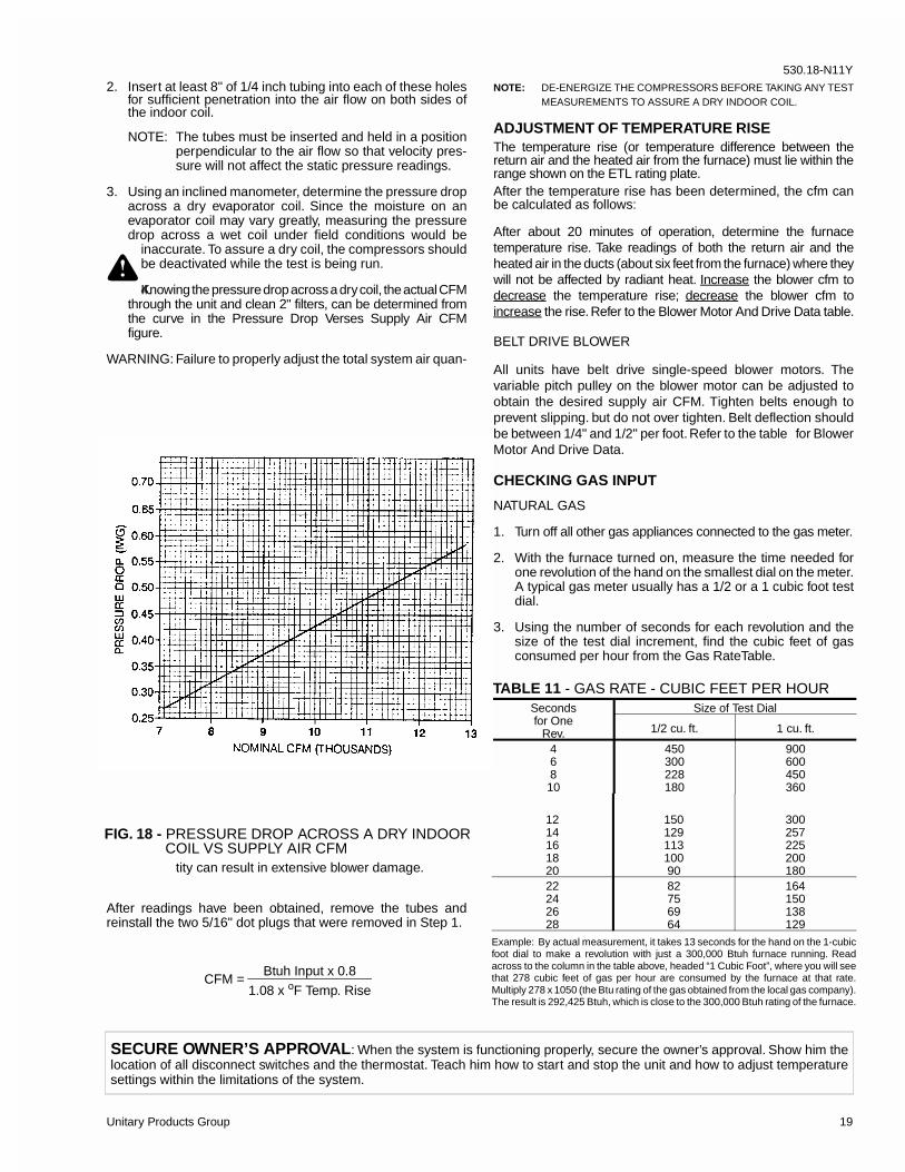
3. Using an inclined manometer, determine the pressure dropacross a dry evaporator coil. Since the moisture on anevaporator coil may vary greatly, measuring the pressuredrop across a wet coil under field conditions would be
inaccurate. To assure a dry coil, the compressors shouldbe deactivated while the test is being run.
4.Knowing the pressure drop across a dry coil, the actual CFMthrough the unit and clean 2" filters, can be determined fromthe curve in the Pressure Drop Verses Supply Air CFMfigure.
WARNING: Failure to properly adjust the total system air quan-
tity can result in extensive blower damage.
After readings have been obtained, remove the tubes andreinstall the two 5/16" dot plugs that were removed in Step 1.
NOTE: DE-ENERGIZE THE COMPRESSORS BEFORE TAKING ANY TESTMEASUREMENTS TO ASSURE A DRY INDOOR COIL.
ADJUSTMENT OF TEMPERATURE RISEThe temperature rise (or temperature difference between thereturn air and the heated air from the furnace) must lie within therange shown on the ETL rating plate.After the temperature rise has been determined, the cfm canbe calculated as follows:
After about 20 minutes of operation, determine the furnacetemperature rise. Take readings of both the return air and theheated air in the ducts (about six feet from the furnace) where theywill not be affected by radiant heat. Increase the blower cfm todecrease the temperature rise; decrease the blower cfm toincrease the rise. Refer to the Blower Motor And Drive Data table.
BELT DRIVE BLOWER
All units have belt drive single-speed blower motors. Thevariable pitch pulley on the blower motor can be adjusted toobtain the desired supply air CFM. Tighten belts enough toprevent slipping. but do not over tighten. Belt deflection shouldbe between 1/4" and 1/2" per foot. Refer to the table for BlowerMotor And Drive Data.
CHECKING GAS INPUT
NATURAL GAS
1. Turn off all other gas appliances connected to the gas meter.
2. With the furnace turned on, measure the time needed forone revolution of the hand on the smallest dial on the meter.A typical gas meter usually has a 1/2 or a 1 cubic foot testdial.
3. Using the number of seconds for each revolution and thesize of the test dial increment, find the cubic feet of gasconsumed per hour from the Gas RateTable.
CFM = Btuh Input x 0.8
1.08 x oF Temp. Rise
SECURE OWNER’S APPROVAL: When the system is functioning properly, secure the owner’s approval. Show him thelocation of all disconnect switches and the thermostat. Teach him how to start and stop the unit and how to adjust temperaturesettings within the limitations of the system.
FIG. 18 - PRESSURE DROP ACROSS A DRY INDOORCOIL VS SUPPLY AIR CFM
Secondsfor One
Rev.
Size of Test Dial
1/2 cu. ft. 1 cu. ft.
46810
450300228180
900600450360
1214161820
15012911310090
300257225200180
22242628
82756964
164150138129
Example: By actual measurement, it takes 13 seconds for the hand on the 1-cubicfoot dial to make a revolution with just a 300,000 Btuh furnace running. Readacross to the column in the table above, headed “1 Cubic Foot”, where you will seethat 278 cubic feet of gas per hour are consumed by the furnace at that rate.Multiply 278 x 1050 (the Btu rating of the gas obtained from the local gas company).The result is 292,425 Btuh, which is close to the 300,000 Btuh rating of the furnace.
TABLE 11 - GAS RATE - CUBIC FEET PER HOUR
530.18-N11Y
Unitary Products Group 19

If the actual input is not within 5% of the furnace rating (withallowance being made for the permissible range of the regulatorsetting), replace the orifice spuds with spuds of the proper size.
NOTE To find the Btu input, multiply the number of cubic feet ofgas consumed per hour by the Btu content of the gas inyour particular locality (contact your gas company for thisinformation - it varies widely from city to city.)
NORMAL MAINTENANCE
CAUTION: Prior to any of the following maintenance proce-dures, shut off all electric power to the unit toprevent personal injury.
Periodic maintenance normally consists of changing orcleaning filters and (under some conditions) cleaning the mainburners.FILTERS - Inspect once a month. Replace disposable or cleanpermanent type as necessary. DO NOT replace permanenttype with disposable. The dimensional size of the replacementfilter must be the same as the replaced filter.MOTORSOutdoor fan motors are permanently lubricated and require nomaintenance.
Ventor motor is factory lubricated for an estimated 10 yearlife.Indoor Blower Motor and Drive - The indoor blower motor
features ball bearings that do not require periodic lubrication.Periodic lubrication of the motor and bearings can extend thelife of components but is optional.
CAUTION: Damage can occur if the bearings are overlubri-cated. Use grease sparingly.
WARNING: Perform all maintenance operations on the blowermotor with electric power disconnected from theunit. Do not attempt to lubricate bearings with theunit in operation.
On an annual basis, check the motor for accumulations of dust,etc. that may block the cooling slots in the motor shell. Check forloose, damaged or misaligned drive components. Check that allmounting bolts are tight. Replace defective parts as required.If desired, every three years remove both pipe plugs at each endshell and clean out any hardened grease or foreign matter.Replace one plug on each end with a clean grease fitting. Usinga low pressure grease gun, pump grease (Chevron SRI-2 orequivalent) into the bearing cavity until new grease shows at theopen port. Do not over lubricate. Run the motor for ten minutesuntil excess grease is purged from the cavity. Replace the plugs.Units are supplied with blower shaft bearings that do not requiremaintenance but may be relubricated if desired. Every threeyears, using a low pressure grease gun, pump grease into thebearing grease fitting until grease just begins to show at theseals. Do not over lubricate. Use any lithium base greaserecommended for ball bearing service.OUTDOOR COIL - Dirt should not be allowed to accumulateon the outdoor coil surface or other parts in the air circuit.Cleaning should be as often as necessary to keep coil clean.Use a brush, vacuum cleaner attachment, or other suitablemeans. If water is used to clean coil, be sure electric power tothe unit is shut off prior to cleaning.
NOTE: Exercise care when cleaning the coil so that the coilfins are not damaged.
Do not permit the hot condenser air discharge to beobstructed by overhanging structures of shrubs.
GAS HEATING UNITS
BURNER & PILOT - Periodically (at least annually at thebeginning of each heating season) make a visual check of thepilot and main burner flame. If necessary, adjust main burnerprimary air shutters to give a distinct, sharp blue flame asexplained under “BURNER AIR SHUTTER ADJUSTMENT”. Ifit is not possible to adjust for the proper flame, the burners mayneed cleaning.
TO CLEAN BURNERS - Remove them from the furnace asexplained in “Burner Instructions”. Clean burners with hot waterapplied along top of the burner.COMBUSTION AIR DISCHARGE - Visually inspect dischargeoutlet periodically to make sure that the buildup of soot and dirtis not excessive. If necessary, clean to maintain adequatecombustion air discharge.
CLEANING FLUE PASSAGES AND HEATING ELEMENTS
With proper combustion adjustment the heating element of agas fired furnace will seldom need cleaning. If the elementshould become sooted, it can be cleaned as follows:1. Remove the burner assembly as outlined in “BURNER
INSTRUCTIONS”.2. Remove the roof over the gas heat section.3. At the top plate from the top draft blower housing and the
top draft blower wheel.4. Remove the screws holding the top of the flue collector box.
Carefully remove the top of the flue collector box withoutripping the adjacent insulation. Then remove the centerdivider plate separating the upper and lower flue boxes.
5. On the inside of the flue collector box, remove the fluebaffles from the tube interiors. Note the last bend of thebaffle fits tightly against the tube forcing the end of the baffleto lock into the tube collar. This collar is formed when thetube is expanded into the end sheet. To remove, move theend of the baffle toward the center of the tube releasing theend of the baffle from the tube collar, then pull straight outof the tube.
6. Using a wire brush on a flexible wand, brush out the insideof each heat exchanger from the burner inlet and flue outletends.
7. Brush out the inside of the flue collector box and the fluebaffles.
8. Run the wire brush down the vent hoods from the fluecollector end.
9. If soot build-up is particularly bad, remove the vent motorand clean the wheel and housings. Run the wire brush downthe flue extentions at the outlet of the vent housings.
MAINTENANCE
FIG. 19 - TYPICAL FLUE BAFFLE INSTALLATION
530.18-N11Y
20 Unitary Products Group

10. After brushing is complete, blow all brushed areas with airor nitrogen. Vacuum as needed.
11. Replace parts in the order they were removed in Steps1 thru 4.
12. When replacing the center and top of the flue collector box,be careful not to tear the adjoining insulation.
13. Ensure that all seams on the vent side of the combustionsystem are air tight. Apply a high temperature (+500°F)sealing compound where needed.
WARNING: Troubleshooting of components necessarily re-quires opening the electrical control box with thepower connected to the unit. Use extreme carewhen working with live circuits! Check the unitnameplate for the correct line voltage and set thevolt meter to the correct range before making anyconnections with line terminals.
WARNING: Prior to any of the following maintenance proce-dures, shut off all electric power to the unit toprevent personal injury.
CAUTION: Label all wires prior to disconnection when servic-ing controls. Wiring errors can cause improper anddangerous operation. Verify proper operation afterservicing.
NOTE: To find the Btu input, multiply the number of cubic feet ofgas consumed per hour by the Btu content of the gas inyour particular locality (contact your gas company for thisinformation - it varies widely from city to city.)
1. The indoor blower motor is a non-inherently protectedthree-phase motor. Protection is provided by an overloadrelay for overcurrent and fuses for short circuit. If the motorfails to run, check the line voltage circuit and control voltagecircuit per the following procedure:
a. If the Indoor Blower Motor does not operate, checkvisually that contactor M3 is pulled in. If so, check forline voltage between all three phases at the line termi-nals of the Blower Overload Relay (BOR). If line voltageis found, check the leads to the blower motor for opencircuit. If line voltage is found at the motor leads (insidethe conduit box on the motor shell), disconnect themotor and check for open windings per the motor wiringdiagram. If open windings are found, replace the motor.If line voltage is not found at the BOR, trace the leadsback to the field supply terminal block, checking for anopen circuit or blown fuses.
b. If the contactor M3 is not pulled in, check for controlvoltage (24V) at the M3 coil. If voltage is found, replacethe contactor. If control voltage is not found at M3, checkfor voltage across terminals 95 & 96 of the BOR. Ifvoltage exists, the BOR is open on overload. The BORshould be set to the auto reset position. The BOR mustcool down in order to reset. If the BOR will not reset,replace the BOR. If the BOR resets and M3 pulls in, butthe indoor blower motor will still not run, refer to para.(a) for troubleshooting the line voltage supply circuit. Ifcontrol voltage is not found at the BOR, trace the circuitback to the relay board and thermostat per the unitwiring diagram. Replace any defective components.
2. Draft motor operates and furnace lights but supply airblower does not start after a short time delay with roomthermostat fan switch set to “AUTO”.
a. Set fan switch to “ON”. If blower motor runs, go to Step f.If it does not, check to see if line voltage is beingsupplied to the contacts of the contactor (M3), and if thecontactor is pulled in. Check for loose wiring.
b. If contactor (M3) is pulled in, proceed with the trou-bleshooting steps indicated in Step 1 above.
c. If (M3) is pulled in and the blower motor still does notrun, replace the blower motor.
d. If (M3) is not pulled in, check for 24 volts at the (M3) coil.If 24 volts is present, replace the (M3) contactor.
e. If 24 volts is not present at the (M3) coil, check for loose24 volt wiring back to the relay board. Check controlwiring to the room thermostat. If all is fine, replace therelay board.
f. If the blower motor runs with the fan switch in the “ON”position but does not run soon after the furnace hasignited with the fan switch in the “AUTO” position, checkfor loose 24 volt wiring between the relay board in themain control box, the Mate-N-Lok connector in thepartition between the evaporator and gas heat sectionsand the time delay relay (ETD).
g. If all control wiring is fine, check for 24 volts at the relayboard. If 24 volts is present, replace the relay board. If24 volts is not present, replace the (ETD) relay.
NOTE: The furnace may shut itself down on a high tempera-ture condition during the procedure, but this will noteffect the test if it is done within 5 minutes of furnaceshut-down.
3. The supply air blower operates but the draft motor does notwhen the room thermostat is set to call for heat and the fanswitch in the “ON” position.
a. The draft motor has inherent protection. If the motor shellis hot to the touch, wait for the internal overload to reset.
b. If the motor shell is cold with the room thermostat callingfor heat, check for line voltage at the motor’s Mate-N-Lok connector attached to the evaporator partition. Ifline voltage is present, replace the draft motor.
c. If line voltage is not present, check for line voltage at theheat relay (RW1) contacts in the main control box andcheck to see if the (RW1) is pulled in.
d. If the (RW1) relay is pulled in, check for a loose linevoltage connection.
e. If the (RW1) relay is not pulled in, check for 24 volts atthe (RW1) coil. If 24 volts is present, replace the (RW1)relay. If 24 volts is not present, check for a loose 24 voltconnection back to the relay board and check the con-nections from the room thermostat to the relay board. Ifall connections are correct, replace the relay board.
TROUBLESHOOTING
Cont’d.
530.18-N11Y
Unitary Products Group 21

4. The draft motor runs but the furnace does not light and thesparker does not spark.
a. The ignition control (IC1, IC2) may be locked out due toeither a flame roll out or 100% shut off. These safetyfeatures are described above. If lock-out has occurred,24V must be removed from the ignition controls. This isdone at the unit or by resetting the room thermostat.After resetting 24V, check for proper furnace operation.If lock-out continues to occur, locate the source of theproblem and correct.
b. Check all 24 volt connections from the relay board toand in the gas heat section. Check low voltage connec-tions to the (ETD) located in the control box.
c. If the furnace is hot, it may be out on an over-tempera-ture condition, wait for limit reset.
d. If the furnace is cold, check for 24 volts at wire 241attached to the electronic time delay (ETD) located inthe main control box. If 24 volts is not found, replace theETD.
e. With the draft motor running, check for 24 volts atterminal 4 of (RW1-2) and (RW2-1). If 24 volts is notpresent, the centrifugal switch (CS) has not closed orhas gone bad. Check the line voltage to the unit - if it iscorrect, replace the draft motor. If line voltage is low, callthe power company.
f. Check for 24V at terminal 2 of (RW1-2 and RW2-1). If24V is not present, check for 24V at (RW1 and RW2)relay coils. If these relays are pulled in, then check fora loose connection at terminal 2 and terminal 4 of eachrelay. If no problem is found, then replace (RW1 and/orRW2) as required.
g. If 24 volts is present at the ignitor controls, check allcontrol wiring at the ignitor controls and the high tensionwire to the ignitors. Check that the ground wires fromthe ignitor controls, the gas valves and pilot burners areall intact and making good electrical connection. Checkto make sure that the ceramic insulator on the pilotignitors or sensors is not broken or cracked, if all areintact, replace the ignition control IC1 or IC2.
5. The draft motor runs and the sparker sparks at the pilotburner but the pilot does not ignite and a gas odor is notdetected at the draft motor outlet.
a. Check to make sure gas is being supplied to the unit.Make sure that the gas pressure to the unit is within theproper limits as described in the “POST START CHECKLIST” and that the pilot adjust screw is allowing someflow of gas as described in “PILOT CHECKOUT”.
b. Check all wiring between the ignitor control and the gasvalve. Check to make sure the ground connections areintact.
c. If the wiring is intact, check for 24 volts across terminals“PV” and “COMMON” on the ignitor control. If 24 voltsis not present, replace the ignitor control.
d. If 24 volts is present, remove the pilot burner andremove the pilot orifice from the pilot burner. The orificeis removed in the direction opposite the flow of gas.Inspect the orifice for obstruction. If it is clear, replacethe main gas valve.
6. The sparker sparks at the pilot burner but the pilot does notignite and a gas odor is detected at the draft motor outlet.
a. Adjust the pilot adjust screw on the gas valve as de-scribed in “PILOT CHECKOUT”.
b. Check the supply pressure as described in “POSTSTART CHECK LIST”. Make adjustments as necessary.
c. Check the pilot orifice for obstruction as described inpara. 5d. Clean as needed but the problem should notbe the gas valve.
7. The pilot burner ignites but the sparker continues to sparkand the main burners do not ignite.
a. Make the same checks and adjustment as described inpara. 6.
b. Make sure that the pilot burner is not bent or damaged.
c. Make sure that the ground connections at the pilotburner, gas valve and ignitor control are intact. Checkthe high tension wire for good electrical connection. Ifall are intact, replace the ignitor module.
8. The pilot burner lights and the spark stops but the mainburners do not light.
a. Check electrical connections between the ignitor con-trol and the gas valve. If intact, check for 24 volts acrossterminals “MV” and “COMMON” terminals. If no voltagedetected, replace ignitor control. If voltage is present,replace gas valve.
9. Furnace lights with roll-out or one burner has delayedignition.
a. Make sure that the pilot burner is aligned properly withthe carryover as described in “PILOT CHECKOUT”.
b. Make sure that the carryovers on adjoining burners arescrewed fast and are level with respect to one another.
10. Main burners light but exhibit erratic flame characteristics.
a. Adjust air shutters as described in “BURNER AIRSHUTTER ADJUSTMENT”.
b. Check the main burner orifices for obstruction andalignment. Removal procedure is described in“BURNER INSTRUCTIONS”. Clean or replace burnerorifices and burners as needed.
TROUBLESHOOTING - Cont’d.
530.18-N11Y
22 Unitary Products Group

REPLACEMENT PARTSCOMPRESSOR SECTION
• Hermetic compressor• Compressor mounting
MOTOR SECTION
• Blower motor• Fan motor• Ventor motor
ELECTRICAL SECTION
• Ignition control• Relay board• Contactor• Circuit breaker• Temperature controls• Capacitors• Relays• Transformers• Connectors
GAS HEAT SECTION
• Heat exchanger• Gas valve• Pilot• Flame sensor• Spark ignitor• Gas manifold• Gas burner
AIR MOVING SECTION
• Blower wheel• Blower wheel housing
REFRIGERANT SECTION
• Evaporator coil• Evaporator coil header• Expansion valve assembly• Condenser coil• Condenser coil header
FABRICATED PARTS SECTION
• Panels• Posts• Covers Drain pans• Base rails• Air hoods
MISCELLANEOUS SECTION
• Air inlet hood screen• Fan guard• Air filters
TO OBTAIN PARTS INFORMATION: Replacement parts and information from OUR current parts list for this unit are available toyour servicing contractor through our local distributor. The name and address of our nearest distributor may be obtained byconsulting the Yellow Pages of a local telephone directory.IMPORTANT: In order to supply the correct part or information from the parts list, our distributor will need to be provided with thecomplete model number listed on the rating plate located on your unit. See page 2 for Product Nomenclature.WARNING: IMPROPER INSTALLATION, ADJUSTMENT, SERVICE OR MAINTENANCE CAN CAUSE INJURY OR PROPERTYDAMAGE. CONSULT A QUALIFIED INSTALLER, SERVICE AGENCY OR YOUR LOCAL GAS SUPPLIER FOR INFORMATIONOR ASSISTANCE.
530.18-N11Y
Unitary Products Group 23

Unitary Products Group5005 York Drive, Norman, Oklahoma 73069Subject to change without notice. Printed in U.S.A.Copyright by York International Corporation 1999. All Rights Reserved. Code: SBY 530.18-N11Y