Embed Size (px)
Citation preview

Fans | Air Handling Units | Air Distribution Products | Fire Safety | Air Curtains and Heating Products | Tunnel Fans
Constant & Variable air volume controllersAir volume the smart way

Air Volume Control
SystemairTrust-We work to gain your trust
We consider your trust in us as a supplier an important goal. It is always included in our work on all levels and in all areas whether it is a question of cooperation, quality, deliveries or documentation. This catalogue is of course a part of this work.
With this catalogue, which features the new Optima Series Air Vol-ume Control Units, we want to give you as a customer a general overview of what Systemair can offer within this field. More detailed information is available in our Online catalogue at www.systemair.com and as downloadable software. Systemair’s range of fans, air dis-tribution products and accessories also appears in our printed main catalogue.
Our product development leads the field - latest technologies in unit design, fans, motors and heat recovery interact to give high efficiency and with that low power consumption. Systemair has grown each year since the start and we aim to continue with this trend.
Systemair strives to be a reliable supplier of quality products. We help our customers to focus on their own business. Reliable deliveries give the customer greater possibilities to quickly complete a job, and move on to the next project.
At Systemair we call this Trust.
© Systemair 2011. Systemair reserves the right to make technical changes. For updated documentation, please refer to www.systemair.com

1
Air Volume Control
OfficesOffice buildings generally require good ventilation during the day as well as heat and cooling recovery and recondi-tioning of supply air depending on external conditions. Ventilation systems with demand control should be consid-ered for offices where staffing levels vary. As a rule, offices develop an excess of heat produced by people, lighting, so-lar radiation, computer equipment, etc. In many cases there is a need to cool the air and prevent uncomfortably high temperatures. In larger buildings that accumulate heat en-ergy easily, you should consider employing night cooling. If the office is in a city environment, a higher filtration class should be used. In an office environment, there is also con-siderable need to reduce the noise generated by the ventila-tion system.
Schools and nurseriesA school environment means a lot of people present at certain times of the day, i.e. generally there are relatively large variations. This means that it should be possible to use demand control for the ventilation system. Normally, with heat and/or cool recovery is warranted. There will be short periods during the year when heating may be required. However if there is effective sunscreening, then air recon-ditioning is rarely required. High demand for low noise lev-els. At day nurseries, activities, such as cooking, that create odours are common, so there is often a need for supply air and extract air to be kept separate. There must be heat recovery in the form of a plate heat exchanger, for example.
ShopsAs a rule, the number of people in a shop changes con-stantly throughout the day, making a control-on-demand ventilation system the sensible option. Recirculating air in combination with carbon dioxide control (CO2) and heat recovery can be one optimised solution for these types of premises. When there are few people present, CO2 levels will be low and an increased amount of return air can be mixed into the system. As the number of people present increases, the amount of return air is reduced and replaced with fresh outdoor air. If heating is required at night-time, the premises are warmed up using 100% recirculating air.

2
Air Volume Control
IndustryIndustrial premises will often have high airflows if the work carried out there generates high levels of air pollution. If the pollutants are also aggressive, there may be require-ments that affect the choice of material used. Systemair of-fers products for different environmental classes that can cope with tough environments. Filtration of processed air can be adapted to suit specific demands.
HotelsThe requirements for conditioning in hotels are character-ised by demands relating to fire protection, demand control and low noise levels. The choice of air handling unit will probably be affected by these demands. What is important here is good functions for speed control and quiet opera-tion. In addition to quiet air handling units with demand control, Systemair can also supply fans and dampers for fire protection.
Healthcare premisesHealthcare premises can encompass numerous activities, everything from operating theatres to wards. The activity determines the requirements. Operating theatres will have stringent demands for cleanliness and ventilation. Wards require low noise levels. If several areas are served by the same system, the unit must have demand control and possi-bly even sub-systems. Systemair’s range of air handling units can satisfy all requirements relating to healthcare premises, whether these have to do with air cleanliness, noise levels or demand control.

3
Air Volume Control
General DescriptionIn Variable Air Volume (VAV) systems, supply of cool air increases as the cooling load increases, and the air supply decreases as the load decreases.
VAV systems are the most modern, energy efficient all air systems available for comfort air conditioning. VAV systems require less fan capacity than a comparable constant volume system because with VAV only the required air is used. Typically a VAV system fan volume is 60% of a CAV system.
Control of air flow in a VAV system is accomplished through an electronic device, which regulate the amount of supply air to the space in response to a proportional room/space temperature con-troller.
Pressure IndependentSystemair VAV units are pressure independent. The accurate volume control achieved by pressure independent VAV units results in sub-stantial energy savings as well as increased comfort to the occupant. Conditioned air volume is precisely regulated according to demand. A maximum air volume setting avoids drafty air distribution; a mini-mum air volume setting avoids cold air dumping and stuffiness.
Minimum and Maximum air flow requirements are set to suit the space application. “Pressure independent units have controls con-sisting of an inlet duct sensor, damper, controller/actuator and room temperature controller”. The VAV device controls the air sup-ply volume through the inlet duct velocity pressure sensor to main-tain air flow, as the air-conditioning load in the space changes the thermostat signal will reset the VAV controller to change the supply air volume to suit the space requirements. At any given setting, the controller will maintain the required air volume regardless of inlet static pressure changing. This mode of operation is called “Pressure Independent”.
Variable Air Volume units allow the design to take full advantage of shifting loads from lights, occupancy, solar and equipment diversity, which typically leads up to a 40% saving in the total air volume re-quired. Consequently, the central plant and ducting would cost less, thus compensating for the additional cost of VAV terminal units and fan speed controls.
Systemair offers complete range of VAV’s factory tested and cali-brated. The VAV range offered are as following:
1. Round single skin VAV units (Optima-R), used in installations for return or supply air in low pressure systems as single-zone
control
2. Round double skin VAV units (Optima-R-I), used in installations for return or supply air in medium to high pressure systems as single-zone control
3. Round to rectangular single skin insulated VAV units (Optima-R-S), used in installations for return or supply air in medium to high pressure systems as multi-zone control
BenefitsThe VAV system offers some advantage and benefits over conven-tional systems as given below
a) Fan energy savings from longhour usage at reduced volumes, also installed fan horsepower reductions.
b) Greater flexibility in respect to varying loads, which are easier zoned, resulting in occupancy controlled comfort and energy saving.
c) Reduced installation and set-up cost.
d) Reduced system energy consumption cost.
e) Single unit for easy mounting.
f) Integrated high efficiency sound attenuator.
g) Suited for mounting of all controls according to customer speci-fication.
h) Accurate air volume control with centre averaging multi-point airflow differential cross velocity pressure sensor.

4
Constant Air Volume
DescriptionThe air flow regulator RDA is an element placed inside the duct in order to obtain a constant flow within a pressure range from 50 to 200 Pascal. It is used in ventilation or air conditioning systems for supply or return air.
Ordering codeRDA-80/1580 - size15 - air volume
FunctionThe air is forced to pass through predetermined space in which a flap can change the position according to the specified air flow. The flap is attached on to a calibrated spring and therefore no auxiliary power is needed.
DesignRDA is made from plastic material (polystyrene) classified M1 in grey colour. Maximum temperature is 60° C.
MountingRDA is inserted directly into a horizontal or vertical circular duct. It is fixed and kept airtight by a lip seal. Arrow indicates the airflow. If the unit is placed in supply duct, the space between the diffuser and the unit must be at least 3x diameter of the duct. If used for return air the space must be 1x diameter of the duct.
Dimensions
Diagram
Airflow (m3/h)
Lw dB(A)50 Pa 100 Pa 150 Pa 200 Pa
15 25 29 32 3530 26 31 35 3845 27 33 36 3960 32 37 39 4275 32 37 40 4290 32 38 41 44120 30 34 39 42150 33 37 41 45180 34 40 44 47210 34 40 42 44240 35 41 44 47270 37 43 45 49300 33 37 42 45
RDA
Size L (mm) D1 (mm) D2 (mm)80 55 76 73100 60 96 93125 90 120 117160 89 456 147

5
Constant Air Volume
RPK-R & RPK-R-IConstant air flow regulator
RPK-R main dimensions
RPK-R-I main dimensions
DescriptionRPK-R is a round constant air flow regulator which is used for exact mechanical setting of required air volume in ventilation systems with-out need of any other energy. RPK-R is available in two versions:
RPK-R without outside insulation.RPK-R-I with outside 50 mm thick heat and sound insulation.
RPK-R is characterized by:• regulation accuracy• easy mounting• maintenance-free• tight connection with the duct
DesignThe RPK-R is manufactured from galvanized sheet metal only the blade is from aluminium. All steel parts are zinc plated, spring is made from high quality steel. Sliding bearing is suitable for high tem-peratures and doesn´t require any lubrication. The cover of adjust-ing mechanism is made from ABS plastic and the plastic functional parts are from PA plastic. The outside insulation is made from 50 mm thick glass fiber material with outside steel casing.
FunctionThe RPK-R enables regulation of individually required amounts of air in separate ventilation system zones. RPK-R works in tempera-ture from -20 to 80°C and relative humidity up to 80%. Recom-mended air flow velocity is from 3 to 8 meters per second at pressure difference to Δp 500 Pa. Accuracy is ±5 %(±10% for outer settings).
MountingRegulator can be mounted to horizontal, diagonal or vertical duct. The blade must be always horizontal. It is necessary to pay attention to correct direction of mounting, so that the air is entering the regu-lator according to the arrow direction, which is located on regulator casing. Connecting the duct and the regulator is done according to its size with grub screws ø3,2x13 to ø3,9x16, or with rivets of the same diameters and the connection is sealed with sealing tape. After mounting, set the required air volume by turning the working screw on the controller box.
L
45 L1
Ø D
40
L2
L3L
45 L1
Ø D
40
Ø D
2

6
Constant Air Volume
Technical part
Way of mounting RPK-R and RPK-R-I
L min = 3.D
Air flow direction
Ø D
Front view
80150
Size v (m.s-1)
q (m3.h-1)
øD (mm)
øD2 (mm)
L (mm)
L1 (mm)
L2(mm)
L3(mm)
m(kg)
m(i)(kg)
80 4,3-8,4 75-140 78 170 350 260 76 123 0,8 1,7100 3,7-7,5 100-200 97 190 350 260 86 136 1 2,1125 3,2-7,1 125-300 122 215 360 270 100 148 1,2 2,4140 3,6-6,4 190-340 137 230 370 280 107 156 1,4 2,8160 4,3-8,9 300-620 157 250 380 290 117 166 1,6 3,2180 2,8-8,1 250-720 177 270 390 300 128 176 1,9 3,6200 3,2-7,3 350-800 197 290 400 310 138 186 2,1 4250 3,8-7,5 650-1300 247 340 425 335 164 208 3,3 5,8315 3,1-6,0 850-1650 312 405 500 410 196 243 5 8,3
Size q (m3.h-1)
q (l.s-1)
Accuracy(%)
Pmin(Pa)
80
75 20,8 15 100100 27,8 15 100120 33,3 10 100140 38,9 10 100
100
100 27,8 15 65150 41,7 10 65175 48,6 10 80200 55,6 10 100
125
125 34,7 15 65200 55,6 10 65250 69,4 10 80300 83,3 10 100
140
190 52,8 15 65250 69,4 10 65300 83,3 10 80340 94,4 10 100
160
300 83,3 15 65400 111,1 10 65500 138,9 10 80620 172,2 10 100
180
250 69,4 15 65400 111,1 10 65600 166,7 10 80720 200,0 10 100
200
350 97,2 15 65500 138,9 10 65700 194,4 10 80800 222,2 10 90
250
650 180,6 15 65900 250,0 10 651100 305,6 10 801300 361,1 10 90
315
850 236,1 15 651200 333,3 10 651500 416,7 10 801650 458,3 10 90

7
Constant Air Volume
RPK-S and RPK-S-IConstant Air Flow Regulator
DescriptionRPK-S is a square constant air flow regulator which is used for exact mechanical setting of required air volume in ventilation sys-tems without need of any other energy. RPK-S is available in two versions:
RPK-S without outside insulation.RPK-S-I with outside 50 mm thick heat and sound insulation.
RPK-S is characterized by:• regulation accuracy• easy mounting• maintenance-free
DesignThe RPK-S is manufactured from galvanized sheet metal only the blade is from aluminium. All steel parts are zinc plated, spring is made from high quality steel. Sliding bearing is suitable for high temperatures and doesn´t require any lubrication. The cover of ad-justing mechanism is made from ABS plastic and the plastic func-tional parts are from PA plastic. The outside insulation is made from 50 mm thick glass fiber material with outside steel casing.
FunctionThe RPK-S enables regulation of individually required amounts of air in separate ventilation system zones. RPK-S works in tem-perature from -20 to 80°C and relative humidity up to 80%. Rec-ommended air flow velocity is from 3 to 8 meters per second at pressure difference to Δp 500 Pa. Accuracy is ±5 %(±10% for outer settings).
MountingRegulator can be mounted to horizontal, diagonal or vertical duct. The blade must be always horizontal. It is necessary to pay atten-tion to correct direction of mounting, so that the air is entering the regulator according to the arrow direction, which is located on regulator casing. Connecting the duct and the regulator is with flanges. After mounting, set the required air volume by turning the working screw on the controller box.
Size q (m3.h-1)
a (mm)
b (mm)
m (kg)
m(i)(kg)
200x100 330-580200
100 2,9 5,3200x200 510-1200 200 3,7 6,6300x100 470-850
300100 3,7 6,6
300x150 600-1350 150 4,1 7,2300x200 800-1670 200 4,6 8,0400x200 1100-2400
400
200 5,4 9,3400x250 1750-3400 250 6,1 10,1400x300 1700-3600 300 6,5 10,8400x400 2000-5400 400 9,0 13,7500x200 1500-3200
500
200 6,2 10,5500x250 2300-4500 250 6,7 11,0500x300 2400-4300 300 7,0 11,7500x400 2400-5500 400 10,1 15,1500x500 3800-6500 500 13,0 18,6600x200 1500-3500
600
200 7,0 12,3600x250 2550-5100 250 7,4 12,8600x300 2700-5000 300 10,2 15,3600x400 2900-5500 400 11,4 17,0600x500 3000-9000 500 14,6 20,7600x600 4250-8600 600 15,8 22,6

8
Constant Air Volume
Main dimension of RPK-S Main dimension of RPK-S-I
400
a+100 42
b+10
0
b
(b+2
1)±2
a
(a+23)±3
400
a+50
b+50
b
(b+2
1)±2
a
(a+21)±3
a+67
Way of mounting RPK-S
400Lmin = 3 x d ef
AIR FLOW DIRECTION ADJUSTING OF AIR FLOW VOLUME
b x a

Variable Air Volume
9
Optima RCircular variable air volume unit
Highlights:• Blade tightness class 4 according to EN 1751 • Casing tightness class C according to EN 1751• ILH Hygienic certification VDI 6022 & VDI 3803 for Standard
climatisation & Hospitals• Very high accuracy of 5 %• Air speed from 2 to 12 m/s• Works up to 1000 Pa pressure difference
FunctionSystemair circular VAV terminal units are available in two versions:
Single skin Optima R & Double skin Optima R-I
Single skin circular VAV terminal units are commonly used for re-turn air applications or for supply applications at low system pres-sures. Double skin circular VAV terminal units are commonly used for supply or for return air applications at medium to high system pressures. Terminal units are ideal for single zone control with supply and return in Master and Slave setup such as offices, hotel rooms or meeting rooms where the required cooling and heating load will vary on demand.
DesignVAV unit housing constructed of galvanized steel sheet, large surface pleated for extra stiffness. In Optima R-I the external acoustic insula-tion of fiber glass material is designed to absorb the radiated sound power level generated by the damper assembly. The insulation is once again is covered by a secondary galvanized sheet steel to protect the insulation and to add to the low frequency sound radiated in high pres-sure systems.
Special design of centre averaging multi-point airflow differential cross velocity pressure sensor assures an accurate air flow readings even in difficult installations. Button punch snap lock seams, lock form with airtight nylon bearings to assure low casing leakage.
Available SizesInlet/outlet : from ø 80 to ø 630 mm
ControlsThe VAV terminal units are as standard equipped with Belimo com-pact controller without any MP or other communication capability to be used as stand alone or in Master and Slave setting.
The compact controllers which are supplied with MP-Bus commu-nication capability, can be connected later in time to building manag-ment systems to create a zone controle by creating bus-rings solutions
The compact controllers are equally available with MP-Bus and LON communication capability on demand.
The compact controllers which are supplied only with MP-Bus com-munication can be connected later in time with other Bus-Interfaces. Compact controllers are factory calibrated prior to dispatch. * All dimensions given in mm in accordance to EN 1506 øD are the Inlet-Outlet dimensions
Size øD (mm) L (mm)80 78 400100 97125 122
600140 137160 157180 177200 197
800225 222250 247280 277315 312355 352
1000400 397500 497630 627
L
Ø D
92-110
4545
L
Ø D
75
4545

Variable Air Volume
10
Optima RSSingle skin variable air volume unitRound inlet and rectanglar oulet
Highlights:• Blade tightness class 4 according to EN 1751 • Casing tightness class C according to EN 1751• ILH Hygienic certification VDI 6022 & VDI 3803 for Standard
climatisation & Hospitals• Very high accuracy of 5 %• Inlet air speed from 2 to 12 m/s• Works up to 1000 Pa pressure difference• Inside 30 mm noise insulation with anti abrasive layer
FunctionSingle skin round to square VAV terminal units is commonly used for supply air applications or for return air applications at low to medium system pressures. Optima-RS VAV terminal units are ideal for multi-zone control with supply and return in master and slave setup such as offices, hotel rooms or meeting rooms where the required cooling and heating load will vary on demand.
DesignVAV unit housing constructed of galvanized steel sheet, large surface pleated for extra stiffness. Internal thermal acoustic insulation of fibre glass material, dual density insulation cover tissue is used to protect the fiberglass insulation to protect the deterioration of the insulation for air speeds of 20-25m/s.
Acoustic insulation in the housing has aerodynamic flow for extra low sound level.
Double skin low leakage elliptical damper with airtight neoprene gas-ket seal. Special design of centre averaging multi-point airflow dif-ferential cross velocity pressure sensor assures an accurate air flow readings even in difficult installations. Button punch snap lock seams, lock form with airtight nylon bearings to assure low casing leakage. Rectangular outlet with M8 riveted nuts, suited for connecting to duct flange. 12 mm aluminium shaft with nylon bearings
Available SizesInlet/outlet : from ø 100 to ø 400 mm
Controls:The VAV terminal units are as standard equipped with Belimo com-pact controller without any MP or other communication capability to be used as stand alone or in Master and Slave setting.
The compact controllers which are supplied with MP-Bus commu-nication capability, can be connected later in time to building manag-ment systems to create a zone controle by creating bus-rings solutions
The Compact controllers are equally available with MP-Bus and LON communication capability on demand.
The compact controllers which are supplied only with MP-Bus communication can be connected later in time with or per-zones with other Bus-Interfaces. Compact controllers are factory calibrated prior to dispatch.
Dimensions and Airflow
* All dimensions given in mm in accordance to EN 1505 ØD are the Inlet dimensions
Size øD (mm)
L (mm)
L0 (mm)
L1 (mm)
W (mm)
H (mm)
W1(mm)
H1(mm)
100 97450 150 300 200
200
260
260
125 122140 137160 157
600200
400 250 310180 177200 197 700
500400 460
250 247 750250
500 250 560 310315 312
950 700600 350 660 410
400 397 700 400 760 460
75
L
45
W
H
L0 L1
øD
W1
H1

Accessories
11
Accessories• Attenuators
Size ø D(mm)
L nom(mm)
ø D1(mm)
L(mm)
m(kg)
100-300 97 300 200 360 2,28100-600 97 600 200 660 4,09100-900 97 900 200 960 5,18100-1200 97 1200 200 1260 6,46125-600 122 600 224 665 4,39125-900 122 900 224 965 6,2125-1200 122 1200 224 1265 7,47150-600 147 600 250 600 5,37160-600 157 600 260 670 5,37160-900 157 900 260 970 7,48200-600 197 600 300 685 6,9200-900 197 900 300 985 9,74250-600 247 600 355 600 8,55250-900 247 900 355 900 11,7315-600 312 600 415 600 11,8315-900 312 900 415 900 16,3355-900 352 900 560 900 25,2400-900 397 900 600 900 24,3
Optima ASquare Attenuator
Optima MMultioutlet box
LDCCircular Attenuator
Size W(mm)
B(mm)
L(mm)
m(kg)
200x200-1000 200200
1000
9,1250x200-1000 250 10,2400x200-1000 400 13,4500x250-1000 500 250 19,1600x350-1000 600 350 22,7700x400-1000 700 400 26,4
Size øD in (mm)
øD out (mm)
B(mm)
H(mm)
L(mm)
100-80 97 78 250 190 150100-100 97 300 170125-100 122 97 300 210 170125-125 122 350 190140-100 137 97 300 230 170140-140 137 380 210160-125 157 122 350 250 190160-160 157 420 230180-140 177 137 380 270 210180-180 177 460 250200-160 197 157 420 290 230200-200 197 500 270225-180 222 177 460 320 250225-225 222 560 300250-200 247 197 500 340 270250-250 247 610 330280-225 277 222 560 370 300280-280 277 670 370315-250 312 247 610 410 330315-315 312 740 390355-280 352 277 670 450 370355-355 352 820 430400-315 397 312 740 480 390400-400 397 910 470
W20
ø9
L
B20
øDin
øD out
øD out
øDou
tøD
out
H
B
L 12
45
L
ø D
ø D
1

Accessories
12
• Re-heat and cooling battery
VBC-2VBC-2 water heating battery for heating air in ventilation systems with circular ducts.
Aluzinc-coated casing, heat transmission element with copper tubes and aluminium fins. Removable cover for cleaning the unit.
The water-heating battery can be installed in a horizontal or a verti-cal duct with optional direction of airflow. Max operating tempera-ture 150 °C Max operating pressure 1,6 MPa (16Bar) 2-rows battery
Dimensions
Size øD(mm)
B(mm)
H(mm)
ødy(mm)
F(mm)
G(mm)
K(mm)
L(mm)
m(kg)
125-2 123 179 225 10 137 40 300 380 3.8160-2 158 253 300 10 212 40 300 380 5.7200-2 198 253 300 10 212 40 300 380 5.7250-2 248 328 385 22 250 40 300 380 8.2315-2 313 460 460 22 325 40 300 380 10.6
CWKCWK water-cooling battery for circular ducts Casing of galvanised sheet steel with copper tubes and aluminium fins. Inspection covers for easy cleaning and maintenance. Connection sleeves with rubber seal. Max operating temperature 150 °C Max operating pressure 1,6 MPa (16Bar)
Dimensions
Size øD(mm)
B(mm)
H(mm)
ødy(mm)
F(mm)
G(mm)
K(mm)
L(mm)
m(kg)
125-3-2.5 123 326 255 10 175 40 300 276 6.5160-3-2.5 158 326 255 10 175 40 300 276 6.7200-3-2.5 198 411 330 10 250 40 300 276 9.4250-3-2.5 248 486 405 22 325 40 300 276 11315-3-2.5 313 560 504 22 400 40 300 276 14.3

Accessories
13
VBRVBR Water-heating battery Water-heating battery for heating air in ventilation systems with rectangular ducts. Hot-zinc-coated casing, heat transmission element with copper tubes and aluminium fins. In cold conditions, a frost protection device with sensor should be fitted to reduce the risk of damage from freezing. The water-heating battery can be installed in a horizontal or vertical duct with an op-tional direction.
PGKPGK Cold water-cooling battery for rectangular ducts. Casing from galvanised sheet steel.
Water-battery from copper tubes and aluminium fins. Air vent and drain valve included. Drip pan from stainless steel and condensate connection (R½”). Max working pressure 1.6 MPa (16 bar).
For water connection left or right, Two inspection covers for clean-ing and maintenance. Droplet separator DE as an accessory regard-less of air direction. Recommended for air velocities from 3m/s.
Size A (mm)
c/c A (mm)
B(mm)
c/c B(mm)
E(“)
m(kg)
40-20-2 438 420 238 220 R¾‘‘ 5.5 kg50-25-2 538 520 288 270 R¾‘‘ 7 kg50-30-2 538 520 338 320 R¾‘‘ 8 kg60-30-2 638 620 338 320 R¾‘‘ 9 kg60-35-2 638 620 388 370 R¾‘‘ 10 kg70-40-2 738 720 438 420 R 1‘‘ 12.5 kg80-50-2 838 820 538 520 R 1‘‘ 16 kg100-50-2 1038 1020 538 520 R 1‘‘ 18.5 kg
Size A (mm)
c/c A (mm)
B(mm)
c/c B(mm)
E(“)
m(kg)
40-20-4 438 420 238 220 R¾‘‘ 7 kg50-25-4 538 520 288 270 R¾‘‘ 9 kg50-30-4 538 520 338 320 R 1‘‘ 10.5 kg60-30-4 638 620 338 320 R 1‘‘ 11.5 kg60-35-4 638 620 388 370 R 1‘‘ 13 kg
Size A (mm)
c/c A (mm)
B(mm)
c/c B(mm)
E(“)
m(kg)
70-40-3 738 720 438 420 R 1‘‘ 15.5 kg80-50-3 838 820 538 520 R 1‘‘ 19 kg100-50-3 1038 1020 538 520 R 1‘‘ 22.5 kg
Size A (mm)
c/c A (mm)
B(mm)
c/c B(mm)
E(“)
m(kg)
40-20-4 438 420 238 220 R¾‘‘ 7 kg50-25-4 538 520 288 270 R¾‘‘ 9 kg50-30-4 538 520 338 320 R 1‘‘ 10.5 kg60-30-4 638 620 338 320 R 1‘‘ 11.5 kg60-35-4 638 620 388 370 R 1‘‘ 13 kg
Size A (mm)
c/c A (mm)
B(mm)
c/c B(mm)
E(“)
m(kg)
70-40-3 738 720 438 420 R 1‘‘ 15.5 kg80-50-3 838 820 538 520 R 1‘‘ 19 kg100-50-3 1038 1020 538 520 R 1‘‘ 22.5 kg
Dimensions
Dimensions
Accessories
14
• Valves
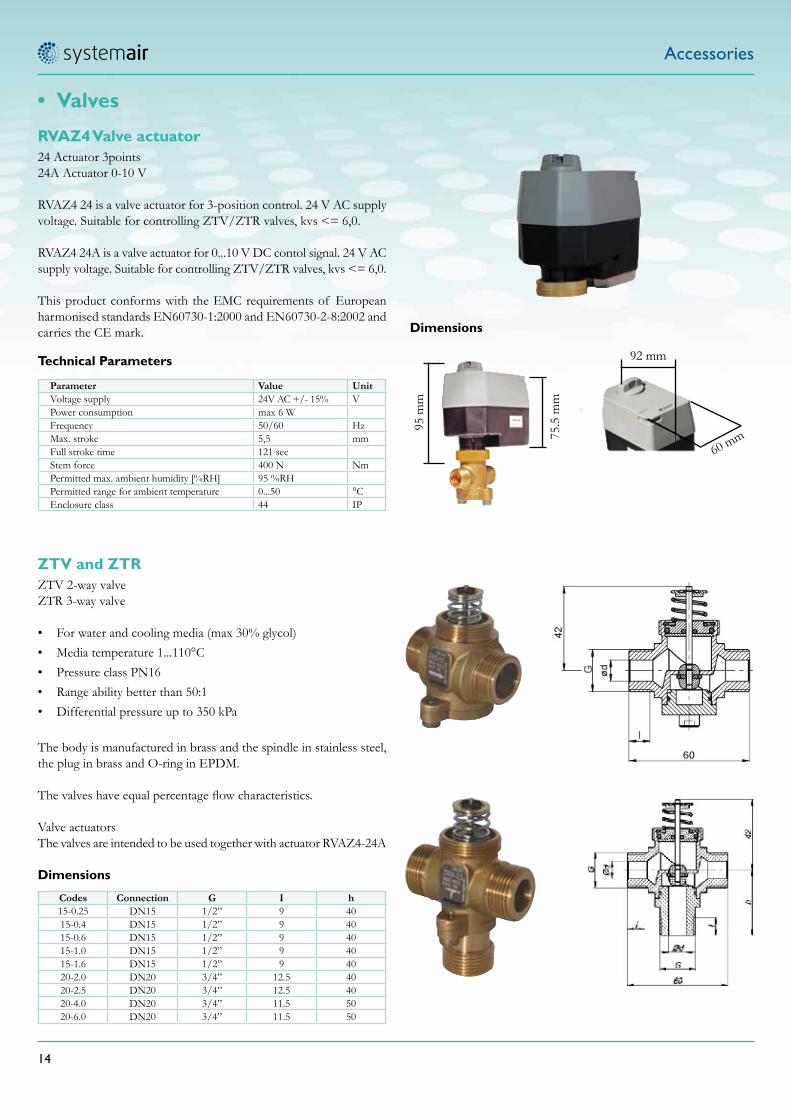
RVAZ4 Valve actuator24 Actuator 3points24A Actuator 0-10 V
RVAZ4 24 is a valve actuator for 3-position control. 24 V AC supply voltage. Suitable for controlling ZTV/ZTR valves, kvs <= 6,0.
RVAZ4 24A is a valve actuator for 0...10 V DC contol signal. 24 V AC supply voltage. Suitable for controlling ZTV/ZTR valves, kvs <= 6,0.
This product conforms with the EMC requirements of European harmonised standards EN60730-1:2000 and EN60730-2-8:2002 and carries the CE mark.
Parameter Value UnitVoltage supply 24V AC +/- 15% VPower consumption max 6 WFrequency 50/60 HzMax. stroke 5,5 mmFull stroke time 121 secStem force 400 N NmPermitted max. ambient humidity [%RH] 95 %RHPermitted range for ambient temperature 0...50 °CEnclosure class 44 IP
Dimensions
Codes Connection G I h15-0.25 DN15 1/2” 9 4015-0.4 DN15 1/2” 9 4015-0.6 DN15 1/2” 9 4015-1.0 DN15 1/2” 9 4015-1.6 DN15 1/2” 9 4020-2.0 DN20 3/4” 12.5 4020-2.5 DN20 3/4” 12.5 4020-4.0 DN20 3/4” 11.5 5020-6.0 DN20 3/4” 11.5 50
Dimensions
Technical Parameters
95 m
m
75.5
mm
92 mm
60 mm
ZTV and ZTRZTV 2-way valveZTR 3-way valve
• For water and cooling media (max 30% glycol)• Media temperature 1...110°C • Pressure class PN16 • Range ability better than 50:1 • Differential pressure up to 350 kPa
The body is manufactured in brass and the spindle in stainless steel, the plug in brass and O-ring in EPDM.
The valves have equal percentage flow characteristics.
Valve actuatorsThe valves are intended to be used together with actuator RVAZ4-24A

VAV Controls
15
Compact or universal air volume control with Belimo.
VAV-Compact – efficient room con-trol with a single unitActuator, controller and sensor in one unit – VAV-Compact provides an economical so-lution for variable and constant air volume control systems in office buildings, hotels, hospitals, etc. Special rotary actuators with a torque of 5, 10 or 20 Nm and linear actua-tors with 150 Nm can be supplied for a wide range of VAV/CAV unit sizes and types. VAV-Compact controllers can be controlled conventionally or via the Belimo MP-Bus®. The MP types can be integrated in a higher-level system – together with one sensor per device – either via a DDC controller with an MP interface or by means of a gateway. The fans are incorporated in an MP-Bus® based Fan Optimiser to facilitate cost-optimised control according to demand.
Human healthwell-being and work performance are cru-cially influenced by room climate. Belimo room and system solutions – a complete range of products for cost-efficient mo-torisation and control of zones and single rooms in the comfort zone, industry, trade and sensitive working areas – are proven in countless installations all over the world.
The cost-efficient way to controlled room climate.
VAV-Universal – flexibility in prob-lematic environmentsThe ready-to-connect VAV-Universal range encompasses rotary and safety actuators as well as controllers with dynamic and static pressure sensors. These devices can be finely tuned to exacting requirements in in-dustry, trade and public buildings. Digital, self-adaptive VRP-M controllers interact with fast-running actuators in laboratories or production areas with a severely polluted room atmosphere to assure an instant supply of fresh air. Depending on what is chosen, the control systems can be integrated in a higher-level fieldbus and equipped – directly or over the MP-Bus® – with the Belimo Fan Optimiser to cut fan energy consump-tion by up to 50%.

VAV Controls
16
Increased conveniencea better working atmosphere, optimum energy efficiency.
VAV-Compact for convenient solutions
Individual room comfort• Wide range of potential applications• Adjustable to each application• Demand-based single-room application• Operation with Fan Optimiser
VAV-Universal with VRP-M controller and fast-running actuators
for sensitive working areas
Instant pure air• Extraction of polluted air• Ready-to-connect control system for maximum safety• Integration in MP-Bus® network• Volumetric flow or pressure control
VAV-Compact with bus connection
Intelligent simplicity• System connection to DDC controller with MP interface via
MP-Bus®• Integration in higher-level systems such as LonWorks®, Kon-
nex, Ethernet TCP/IP, Profibus DP, etc. via MP gateway• Convenient, cost-efficient wiring• Maximum flexibility in new, retrofitted, converted or renovated
buildings
VAV-Compact with Belimo Fan Optimiser for reduced energy consumption
Up to 50% fan energy saving• Optimised consumption and operating costs• Reduced flow noise thanks to lower supply pressure in the air
duct system• Reduced wiring expenses thanks to MP-Bus® network
t
MP gateway
Ethernet
MP-BusFieldbus
FUSetpoint
CAV
MP1
Roomoccupancy
VAV
VAV
MP2
– Cooling requirement– Volumetric flow– Damper position
MP8
Room requirement
M
VAVVAV
STP

VAV Controls
17
Product Range OverviewAir volume and line pressure control
Note:
Separate documentation for the VAV-Com-pact LON version, VRP-M system solution, VAV-Universal, CR24 single-room control-ler, COU24-A-MP fan optimiser, tools and interfaces can be found on the Internet at www.belimo.com.
LMV-D2LONNMV-D2LON
LMV-D2-MPNMV-D2-MPSMV-D2-MPLHV-D2-MP
Sensor
VAV controller
Actuator
VFP-..
VRP-MVRP-M STP[STP pressure]
LM/NM/SM24-A-VVNMQB24-SRV-ST
Accessories
Bus integration and tools:
COU24-A-MPFan optimiser
CR24-..Single-room controller
SG..Position sensor
VRD3 VRPVRP-STP[STP pressure]
VFP-..
LM/NM/SM24-A-V
L/A/F24-A-V with safety function
Integrated
MP BUSTECHNOLOGY BY BELIMO
® MP BUSTECHNOLOGY BY BELIMO
®
UK24LON Interface for LONWORKS® applicationsUK24EIB Interface for EIB-Konex applications
ZTH-VAV VAV-Compact setting device
PC-Tool
Parameterisation and service software– VAV-Compact module– VRP-M module
VAV-Compact LON version MP types
VAV-Universal LON version MP types

VAV Controls
18
Room pressure ratioIn a master / slave connection, any changes in the air system of the master (supply pressure too low, e.g. due to a pressure control fault) are detected and reported to the slave. This guarantees an equal per-centage ratio of supply air to exhaust air.In a master / slave configuration, only one controller can act as mas-ter. However, one master controller can control several parallel slave controllers.
When are master / slave connections used?• In systems with air volume controllers in the supply and exhaust
air that are required to work sequentially• When an equal percentage ratio of supply air to exhaust air is
specified.
Operating volumetric flow settingsThe max - and min values used for the required volumetric flow are set on the master and transferred to the slave by means of a refer-ence signal.
CAV applicationIn constant air volume applications, operating mode control (CLOSED / min etc.) is only set on the master controller.
Slave setting if the room pressure ratio is balancedThe min setting on the slave is always 0%. If the room pressure ratio is 1:1 and all controllers are the same size, the slave controller is set to max 100% / min 0%.
Slave setting if the room pressure ratio is unbalancedThe min setting on the slave is always 0%.
Setting with % scale on the ZTH-VAV hand-operated deviceThe ratio of slave volume to master volume is set as follows with the
max value on the slave controller:
max S% = max S • nom M •100
max M • nom S
max S% = max value that must be set on the controller in %
nom M = Nominal volume of the master unit in m3/h
max M = Maximum volume of the master unit in m3/h
nom S = Nominal volume of the slave unit in m3/h
max S = Maximum volume of the slave unit in m3/h
ExampleRequired: Positive pressure in the room with 20% excess air– Supply air unit:
nom 1600 m3/h / max 1500 m3/h– Exhaust air unit: nom 2400 m3/h / max 1200 m3/hFind: max setting of the slave controller
Setting with PC-Tool / ZTH-VAVThese two setting tools can be used to enter the volumetric flow ratio directly in m3/ h, ll/s or cfm, i.e. there is no need to calculate the setting ratio.
53% =1200 • 1600
•1001500 • 2400
Determination of the master controllerIf both units have:
• Non-identical nom settings, the controller with the lower nom.
• Identical nom settings, the controller with the higher air volume setting acts as master
• Positive pressure in the roomMaster: Supply air unit Slave: Exhaust air unit
• Negative pressure in the roomMaster: Exhaust air unit Slave: Supply air unit
Principle:1. A reference signal, e.g. from a room temperature controller, is
connected to the master input. min and max are set on the master controller.
2. The volumetric flow actual value signal from the master acts as a reference signal for the slave controller. The master is installed on the supply or exhaust air side, depending on the application. See “Determination of the master controller“.
For connection diagram, see page 5 … 6
0 10020 40 60 80
[V]
nom10
0
2
4
6
8
max max
min
Reference signal YExample with mode: 0 … 10 V
The ratio is set with the max pa-rameter on the slave
Volumetric flow[% nom]
The slave min setting «0%» forms the pivot and intersection point
Equal percentageratio
VAV-CompactFunctions
T
M S12
SUPPLY
EXHAUST
Room
Master / slave connection

VAV Controls
19
Room pressure ratioIn a parallel connection, the two VAV units are operated indepen-dently of one another with a common reference signal. The operat-ing volumetric flows of the supply and exhaust air units must be set according to the required room pressure ratio.
The supply and exhaust air controllers work independently of one another, i.e. if a fault occurs in the supply or exhaust air system, the room pressure ratio is impaired for technical reasons. In the worst case, the unit tolerances may be accumulated. This circumstance must be taken into account by the project planning engineer.
When are parallel connections used?• If air volume controllers operate with parallel supply and ex-
haust air (controlled by a common reference variable)
• If the supply and exhaust air devices have different sizes and dif-ferent minimum and maximum volumetric flow settings
• If constant differential control is active between the supply and exhaust air
• In systems with several supply and exhaust air devices
• In circulating air systems for airtight rooms.
Operating volumetric flow settingsThe max and min values used for the required volumetric flow must be set on each VAV controller.
CAV applicationIn constant air volume applications, operating mode control (CLOSED / min etc.) is set on both controllers.
Setting if the room pressure ratio is balanced
Owing to the proportional assignment of the reference signal to the value ranges for max and min, it is possible to operate VAV units with different nominal widths and differentiated ranges parallel to one another.
Setting if the room pressure ratio is unbalanced
The operating volumetric flows of the supply and exhaust air units must be set according to the difference:• Positive pressure ratio in the room Supply air volume > exhaust
air volume
• Negative pressure ratio in the room Exhaust air volume > supply air volume
Volumetric flow[% nom]
Volumetric flowactual value signal U5 Exam-ple with mode:0 … 10 V
0 100 10 30 40 50 60 70 80 90
100% 30 40 50 60 70 80 90
[V]
10
0
1
2
3
4
5
6
7
8
9
min
min
max
max
20
Constantsupply / exhaustair difference
Principle:The reference signal of the temperature controller is connected in a parallel circuit with the reference value inputs of the supply and exhaust air controllers. The operating volumetric flows max and min are set on both controllers.For connection diagram, see page 5 … 6
Parallel connection
SUPPLY
ABL
SUP. EXH.
Room
T
EXHAUST
VAV-CompactFunctions

VAV Controls
20
VAV-CompactConventional applications
Notes• Connection and terminal designations of the motion detector in
accordance with the manufacturer‘s specification• Mode setting on the CAV controller: 0 … 10 V oder 2 … 10 V
CAV single-duct system, occupancy-controlled
Brief DescriptionControl solution for CAV single-room applicationCAV single-duct system, occupancy-controlled Stand-alone opera-tion or integrated in a building automation system (I/O integration)
FunctionsThe CAV controller is controlled by means of the motion detector in two modes on the basis of room occupancy min … max:– Room unoccupied: constant air volume min– Room occupied: constant air volume max
Motion detectorWith switching output for low switching capacity (load 0,24 mA)
VAV-Compact control device..MV-D2-MPVAV-Compact control device for supply air, exhaust air or mixing units, comprising a sensor, VAV controller and actuator for pressure-independent air volume controls.• Damper position feedback controlled via the MP-Bus for de-
mand based fan optimisation.
1 3y
5U5
1 3y
5U5
2~
2~
AC 24 V
CAV 2
2) 1)CAV 1
~
1)Master-Slaveor2) parallel
min Motion detectormax
Act
. val
ue si
g.
Act
. val
ue si
g.
Wiring diagram
Volumetricflow max
min
Roomoccupied
Roomunoccupied
IRC-VAV CAV room solution with motion detectorSingle-duct systems
Function diagram

VAV Controls
21
[V]
10
0
Y
WKWH
ao1
XP K
tR[°C]
Volumetric flow max
IRC-VAV CAV room solution with 0....10V controlSingle-duct systems
Notes• Connection and terminal designations in accordance with the
controller manufacturer’s specification• Mode setting on the VAV controller: 0 … 10 V
1 3y
5U5
1 3y
5U5
2~
2~
AC 24 V
VAV 2
2) 1)VAV 1
~
Refe
renc
e sig
nal
0 …
10
V
Act
ual v
alue
sign
al
0 …
10
V *
Room / DDC controller
Brief DescriptionControl solution for VAV single-room applicationStand-alone operation or integrated in a building automation system (I/O integration)
FunctionsThe 0 ... 10 V V single-room or DDC controller controls the VAV controller with vaiable air volume in the range from min … max, depending on the room cooling needs.
Single-room or DDC controllerWith The 0 ... 10 V output single (cooling sequence).Controller functions in accordance with the manufacturer‘s specifi-cation.
VAV-Compact control device..MV-D2-MPVAV-Compact control device for supply air, exhaust air or mixing units, comprising a sensor, VAV controller and actuator for pressure-independent air volume controls.• Damper position controlled via the MP-Bus for demand based
fan optimisation.
VAV-CompactConventional applications
Wiring diagram

VAV Controls
22
Note
Terminal designations in accordance with the Belimo final control-ling element.
EHOCLOSED
Brief descriptionControl solution for VAV single-room application,
VAV single-duct system, room temperature-controlled, Stand-alone op-eration or integrated in a building automation system (I/O integration)
FunctionsThe CR24-B1 single-room controller controls the connected VAV controllers with a variable air volume in the range from min … max, depending on the room cooling needs. Other functions can be optionally connected (e.g. with a motion detector): energy hold off, standby, etc.
Room temperature controllerCR24-B1 (automatic) CR24-A1
Room temperature controller (15 … 36°C) with an integrated or ex-ternal temperature sensor
• Mode selection with a pushbutton and three LEDs: AUTO, ECO (reduced room temperature for standby or night opera-tion) and MAX (flushing operation with 15’ timer)
• Room protection function (frost / excess temperature)• Inputs for energy hold off, standby operation, external tempera-
ture sensor, summer / winter compensation• VAV system output• Self-resetting start-up and service function• Tool connection for diagnostics, settings and trend recordingsVAV-Compact control device ..MV-D2-MP, VAV-Compact control device for supply air, exhaust air or mixing units, comprising a sen-sor, VAV controller and actuator for pressure-independent air volume controls.
• Damper position controlled via the MP-Bus for demand based fan optimisation.
Note
For technical data and a detailed description of functions, see CR24 product information.
[V]
10
0
2
Y
WKWH
ao1
XP K
tR[°C]
min
max
Functions Description AssignmentVAV VAV system output (0) 2 ... 10 V Output ao1Optional func-tions Description Assignment
EHO Energy hold off (window) Input di1Sensor External temperature sensor NTC 5K Input ai1
Shift External shift 0 ... 10 V(Summer / Winter compensation) Input ai2
Configuration, settings
Setpoint WH range: 15 … 36 °C
Notes• Further VAV applications such as boost (fast heat up), night cool
down (air heated with water or electrically), night cooling, combi-nation available with chilled ceiling.
• Mode setting for VAV controller for this application: 2 … 10 V
U5
CR24-B1
EHO St-By
1 3y
5U5
1 3y
5U5
2~
2~
AC 24 V
1 2 7 86ao1 1 U5 2 4
di2
3 5
ai1/di1 ai2
VAV 2
2) 1)VAV 1
0...1
0V
_~
1) Master-Slaveor2) parallel
External temperature sensor
E x t e r n a l shift
IRC-VAV VAV room solution with CR 24 room controller
Single-duct systemsFunction diagram
VAV singleduct system, room tempreture-controlled
Wiring diagram Input and output assignment
VAV-CompactConventional applications
1 P-Band normal wide2 di2 Stand by Change over
21
DIP switches

VAV Controls
23
IRC-VAV VAV dual-duct solution with CR 24 room controller
Dual-duct systems
max
max
mintR [°C]
HeadingSupply air temperature
Mixing Range Cooling
Volumetric Flow
Hot air
ht cl
Cold air
P-band coolingWkü
VAV dual-duct system, room temperature-controlled
Note
For technical data and a detailed description of
functions, see CR24 product information.
Notes• Terminal descriptions correspond to the Belimo actuator connec-
tion.• Mode setting for VAV controller for this application: 2 … 10 V
Control solution for VAV single-room applica-tionVAV dual-duct system, room temperature-controlledStand-alone operation or integrated in a building automation system (I/O integration)
Functions The two air volume controllers mix the hot and cold air supplied by the dual-duct air conditioning system to obtain the condition re-quested by the CR24-B1 room temperature controller. The constant air volume (CAV) controller for the hot air adjusts to the set max volume for heating. The variable air volume (VAV) controller for the cold air adds the variable amount of cold air requested by the room temperature controller. If cooling needs exceed the hot air volume, the hot-air part is shut off and only cold air is supplied. Optional: The cold-air part can be shut off by means of a switch-ing contact at input d1.
Room temperature controllerCR24-B1(automatic) CR24-A1Room temperature controller (15 … 36°C) with an integrated or external temperature sensor• Mode selection with a pushbutton and three LEDs: AUTO,
ECO (reduced room temperature for standby or night opera-tion) and MAX (flushing operation with 15’ timer)
• Room protection function (frost / excess temperature)• Inputs for cold air shut-off, external temperature sensor, sum-
mer / winter compensation• VAV system output• Self-resetting start-up and service function• Tool connection for diagnostics, settings and trend recordings
VAV-Compact control device ..MV-D2-MPVAV-Compact control device for supply air, exhaust air or mixing units, comprising a sensor, VAV controller and actuator for pressure-independent air volume controls.
Functions Description AssignmentVAV VAV system output (0) 2 ... 10 V Output ao1
Optional functions Description Output ao1
Shut-off CA Cold air shut-off AssignmentSensor External temperature sensor NTC 5K Input ai1
Shift External shift 0 ... 10 V (Summer / Winter compensation) Input ai2
Input and output assignment
U5
CR24-B1
1 3y
5U5
1 3y
5U5
2~
2~
AC 24 V
1 2 7 86ao1 1 U5 2 4
di2
3 5
ai1/di1 ai2
0...1
0V
_~ External temperaturesensor
Cold airshut-off
VAV contr. for adding cold air
CAV controller for hot air
St-By
Shift
Wiring diagram
Configuration, settingsDIP switches
1 2
VAV-CompactConventional applications
1 P-Band normal wide2 di2 Stand by Change over
Setpoint WH range: 15 … 36 °C

24
Product rangeSystemair has an extensive range of ventilation products, the majority of which are fans and air handling units. Other products include a wide range of air terminal devices for various applications. These products are installed in a variety of locations, including homes, offices, healthcare premises, shops, industrial buildings, tunnels, parking garages, training facilities, sports centres. The most common usage is comfort ventilation, but safety ventilation in various forms is also an important market. Smoke gas ventilation and tunnel ventilation are two examples.
FansSystemair is one of the world’s largest sup-pliers of fans for use in various types of property.
Our range includes everything from duct fans with a round connection – the com-pany’s original product - to rectangular duct fans, roof fans, axial fans, explosion-proof fans, and smoke gas fans.
These fans can be supplied in sizes suitable for everything from ducts with a diameter of just 100 mm to large road tunnel fans. All our fans have been developed to comply with stringent requirements and are charac-terised by user-friendliness, a high level of quality and a long service life.
Circular duct fans
Duct fans with a circular connection.
Radial fansSingle-inlet radial fans.
Axial fansAxial fans for duct connection or wall mounting
Jet fansThe jet fan range includes products for garages and road and rail tunnels.
Explosion-proof fansExplosion-proof fans for duct, roof and axial installations.
Rectangular duct fansDuct fans with a rectangular connection.
Box fansFor extract air systems that transport normal or high-temperature media.
Roof fansRoof fans with a circular or square con-nection.
Thermo fansSystemair supplies high temperature fans that can withstand conditions of up to 600°C for 120 minutes

25
Smoke gas fansHigh-capacity fans for evacuation of smoke gases.
Fire dampersDampers that reduce the spread of smoke and fire.
Residential unitsFor homes with living areas of 60-320 m2.
Cooker hoodsGood at capturing odours even at low airflows.
Supply, extract & transfer air ter-minal devicesFor mounting in ceilings or walls.
Nozzle air devicesOptimum air distribution for rooms.
Supply & extract air ventilatorsFor mounting in ceilings and walls
Duct productsDampers, plenum boxes, and duct acces-sories.
Fire safety ventilationSystemair produces fans, dampers and control equipment for protection against smoke and fire certified for use during normal operation and in the event of a fire. The axial fans are certified for instal-lation inside or outside fire risk areas.
Residental ventilationComplete energy-efficient air handling units with heat recovery and built-in con-trol systems. Designed to be mounted over the cooker, on walls or horizontally in attics.
Air terminal devicesSystemair’s range also includes a wide se-lection of air terminal devices for all pos-sible environments and positions. Devel-opment and manufacture take place at a modern factory in Slovakia.

Syst
emai
r Gm
bH –
02/
2011
/ E
2284
www.systemair.com