Embed Size (px)
Citation preview
GSJ: Volume 7, Issue 7, July 2019, Online: ISSN 2320-9186
www.globalscientificjournal.com
CONSTRUCTION AND PERFOMANCE EVALUATION
OF AN ULTRASONIC DISTANCE METER ESEKHAIGBE, F.I., OKOEDION, P., ABODE, H.O
DEPARTMENT OF SCIENCE LABORATORY TECHNOLOGY, AUCHI POLYTECHNIC,
AUCHI, EDO STATE, NIGERIA
CORRESPONDENCE: [email protected]
ABSTRACT
Ultrasonic distance meter can be used to measure distance without contact, which is the use of
ultrasonic wave at 40 KHz for distance measurement. The ultrasonic distance meter employs an
ultrasonic module that consists of an ultrasonic transmitter and receiver, along with an
ATMEGA 328microcontroller. It works by transmitting a short pulse of sound at a frequency
inaudible to the ear (ultrasonic sound). Afterward, the microcontroller listens for an echo. The
MCU calculates the distance based on the speed of sound at 250c ambient temperature and
shows it on LCD display. Using it, we can measure distance up to 4 meter, with an accuracy of
1cm. In this project, we excite the ultrasonic transmitter unit with a 40 KHz pulse burst and
expect an echo from the object whose distance is to be measured with an average accuracy of
3mm and an error difference of 1cm. The importance of this research is calculating accurate
distance for any obstacle that we want to measure. This device can be used in many different
fields such as in Physics, Engineering, Research and Production and other categories, spanning
in endless applications.
Keywords: ultrasonic distance measurement, microcontroller, echo, LCD display and ultrasonic
sensor
GSJ: Volume 7, Issue 7, July 2019 ISSN 2320-9186
302
GSJ© 2019 www.globalscientificjournal.com
INTRODUCTION
According to Li, and Libermann, (2007); defines sound as a mechanical vibration transmitted by
an elastic medium through the displacement of particle within the medium. The range of
frequencies that human(s) can hear is approximately between 20Hz – 20KHz, this range by
definition, is the audible spectrum and varies by individuals and generally reduces with age. The
ear is most sensitive to frequency around 3500Hz. Sound above 20KHz is known as Ultrasound,
while sound below 20KHz is called infrasound.
The speed in which sound travels depends on the medium which it passes through. In general,
the speed of sound is proportional to the stiffness of the medium and its density. Also, the
physical properties and the speed of sound changes with the conditions in the environment. The
speed of sound in the air depends on the temperature. In the air, speed is approximately 345m/s,
in water 1500m/s and in a bar of steel 5000m/s.
When travelling through a medium, the intensity and amplitudes of sound waves reduces, this is
called attenuation and is the main reason why echoes from deeper structures are weaker than
echoes from superficial areas.
GSJ: Volume 7, Issue 7, July 2019 ISSN 2320-9186
303
GSJ© 2019 www.globalscientificjournal.com
RESEARCH METHODOLOGY
COMPONENTS USED FOR THE CONSTRUCTION
In this research work, experimental method of research was used, in carrying out the study.
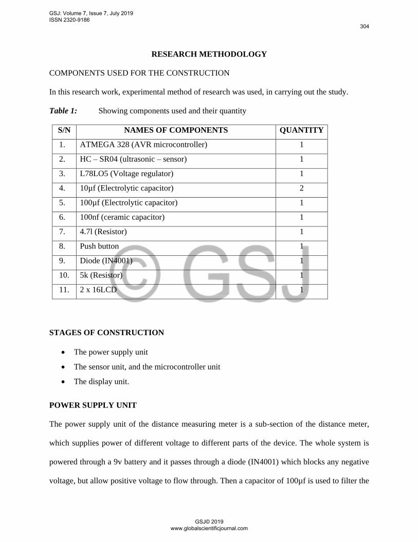
Table 1: Showing components used and their quantity
S/N NAMES OF COMPONENTS QUANTITY
1. ATMEGA 328 (AVR microcontroller) 1
2. HC – SR04 (ultrasonic – sensor) 1
3. L78LO5 (Voltage regulator) 1
4. 10µf (Electrolytic capacitor) 2
5. 100µf (Electrolytic capacitor) 1
6. 100nf (ceramic capacitor) 1
7. 4.7l (Resistor) 1
8. Push button 1
9. Diode (IN4001) 1
10. 5k (Resistor) 1
11. 2 x 16LCD 1
STAGES OF CONSTRUCTION
The power supply unit
The sensor unit, and the microcontroller unit
The display unit.
POWER SUPPLY UNIT
The power supply unit of the distance measuring meter is a sub-section of the distance meter,
which supplies power of different voltage to different parts of the device. The whole system is
powered through a 9v battery and it passes through a diode (IN4001) which blocks any negative
voltage, but allow positive voltage to flow through. Then a capacitor of 100µf is used to filter the
GSJ: Volume 7, Issue 7, July 2019 ISSN 2320-9186
304
GSJ© 2019 www.globalscientificjournal.com
9v coming from the battery and the L78L05, which is the voltage regulator is used to regulate the
voltage to 5v. Then the output of the voltage from the voltage regulator is then passed through an
electrolytic capacitor and ceramic capacitor, which is to ensure that the voltage is filtered well
before entering into the micro controller. The reason why the voltage from the source (Battery) is
filtered well and reduced to 5v is to ensure that, 5v dc voltage which is constant to the
microcontroller is supplied to it and avoid the microcontroller unit, MCU from getting burnt.
SENSOR UNIT
Ultrasonic transmitter emitted an ultrasonic wave in one direction, and immediately starts the
timing, when it is lunched. Ultrasonic spread in the air, and would return when it encounters
obstacles on its path. The ultrasonic receiver would stop timing, when it receives the reflected
wave.
The principle of ultrasonic distance measurement use the already known air spreading velocity,
measuring the time from lunch to reflection when it encountered obstacles, and then calculate the
distance between the transmitter and the receiver according to the time and velocity. Thus, the
principle of ultrasonic distance measurement is the same with radar system.
Distance measurement is express mathematically as:L = C x T
Where L is the measured distance, and C is the ultrasonic spreading velocity in air, also T
represents time (T is half the time value from transmitting to receiving).
Ultrasonic ranging module, HC-SR04 provides 2cm – 400cm non-contact measurement function,
the ranging accuracy can reach to 3mm that is the resolution that it can measure. The modules
include ultrasonic transmitters, receivers and control circuit.
GSJ: Volume 7, Issue 7, July 2019 ISSN 2320-9186
305
GSJ© 2019 www.globalscientificjournal.com
MICROCONTROLLER UNIT
The micro controller used in this project is the AVR ATMEGA 328P, which has 28 pins and 5 of
these pins are dedicated pins. The dedicated pins are those pins that cannot serve any other
purpose, but their functions are specified by the manufacturer, for example: pin 7 which is the
power pin cannot serve any other purpose, but their functions as specified by the manufacturer,
but just for power.
In this project, we make used of internal clock of the ATMEGA 328p, which has internal clock
of 4MHz. The internal clock is used to calculate the time, the echo will return and be sensed by
the sensor and the microcontroller will capture this time to measure the distance. In summary,
the micro controller use the time the sound travelled and the time it returns, that is the time it
sensed the echo
DISPLAY UNIT
The display unit is the section of the distance meter which displays the distance, the
microcontroller is reading in from the HC-SR04 (ultrasonic sensor) device; the display unit also
displays the writings, variables. That the operator or programmer puts into the program that
he/she wants to display. The display unit consists of an LCD (Imo 16L which is a 2 x 16 LCD (2
rows, 16 column) and a preset resistor. The LCD contains crystals, which are located in the
middle of two electrodes. These crystals are transparent when the electrodes are not energized;
while on the other hand, they block light rays from passing through them, thereby forming on
black dot on the screen. The 2 x 16 LCD has 16pins.
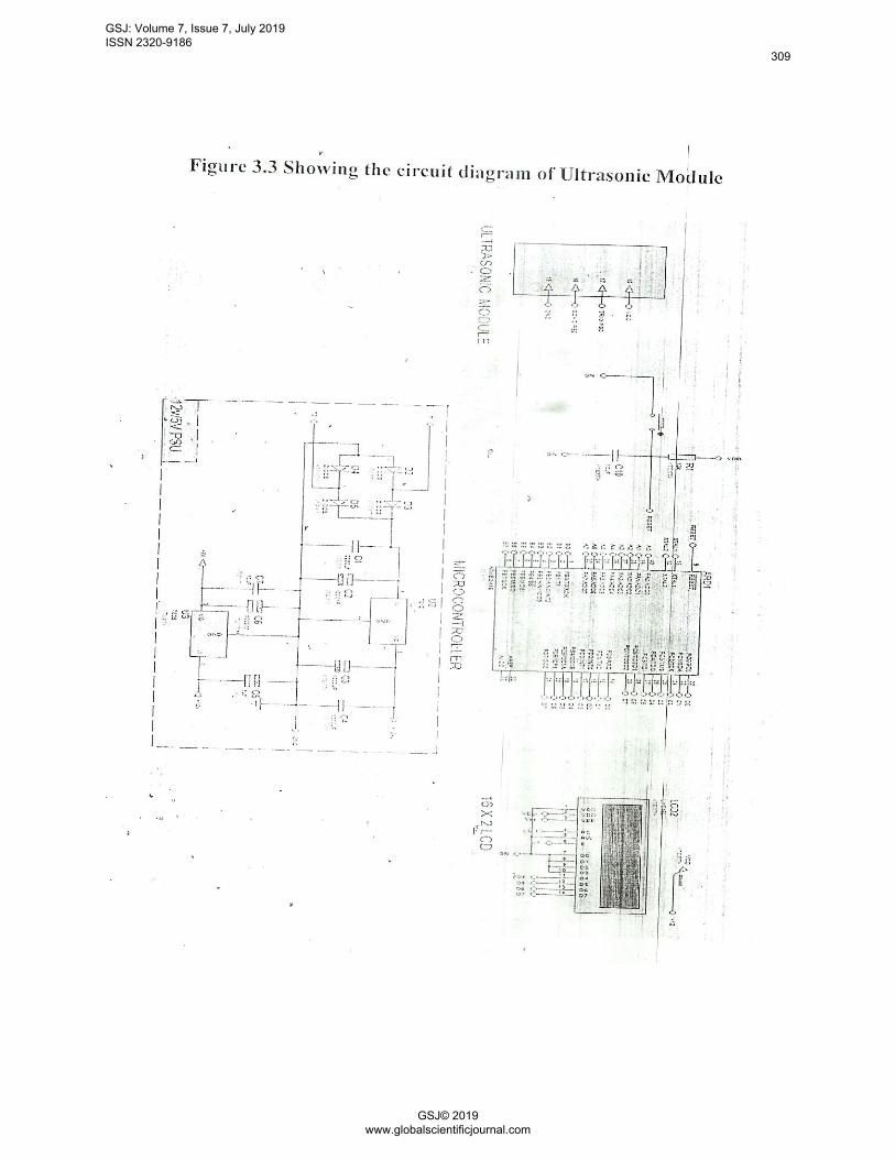
Fig1: Shows the inter-connections between the power supply unit, the sensor unit, the
microcontroller unit, and the display unit
GSJ: Volume 7, Issue 7, July 2019 ISSN 2320-9186
306
GSJ© 2019 www.globalscientificjournal.com
MODULE OPERATING PRINCIPLE
The measurement process is initiated by sending a trigger signal to the ultrasonic module. Firstly,
stransmit at least 10µs high level pulse from the processor to the trig pin of the ultrasonic
module, HC-SR04 as shown in fig2a. The module automatically generates 8 pulses of 40KHz
ultrasonic sound from the transmitter in the direction of the object as shown in fig 2b. When this
sound arrive at the receiver as echo, the module produces a signal at the echo pin whose high
level pulse is proportional to the distance to be measured as shown in fig 2c. The module
automatically generates 8 pulses of 40 KHz ultrasonic sound from the transmitter in the direction
of the object as shown in fig 2b. When this sound arrive at the receiver as echo, the module
produces a signal at the echo pin whose high level pulse is proportional to the distance to be
measured as shown in fig 2c. The MCU calculated the time period between the generation for the
waves and reception of the waves, which is proportional to the distance travelled by the waves
Using the formula, MCU calculates the distance of the object and display the values on the LCD.
Test distance, cm = [High level time x velocity of the sound (340m/s)]
GSJ: Volume 7, Issue 7, July 2019 ISSN 2320-9186
307
GSJ© 2019 www.globalscientificjournal.com
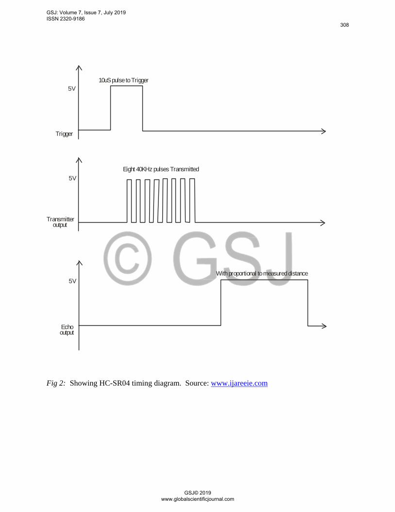
With proportional to measured distance
5V
5V
5V
Echooutput
Transmitteroutput
Trigger
Eight 40KHz pulses Transmitted
10uS pulse to Trigger
Fig 2: Showing HC-SR04 timing diagram. Source: www.ijareeie.com
GSJ: Volume 7, Issue 7, July 2019 ISSN 2320-9186
308
GSJ© 2019 www.globalscientificjournal.com
GSJ: Volume 7, Issue 7, July 2019 ISSN 2320-9186
309
GSJ© 2019 www.globalscientificjournal.com
RESULT ANALYSIS, INTERPRETATION AND DISCUSSION
RESULT ANALYSIS
In this research work, room temperature of 250c was assumed. Hence, the velocity of ultrasonic
in air is taken as 346m/s. Because the travel distance is very short, below 30cm, the travel time is
little affected by temperature. It takes approximately 29.15µs, for ultrasound to propagate waves
through 1cm. therefore, it is possible to have 1cm resolution in the system.
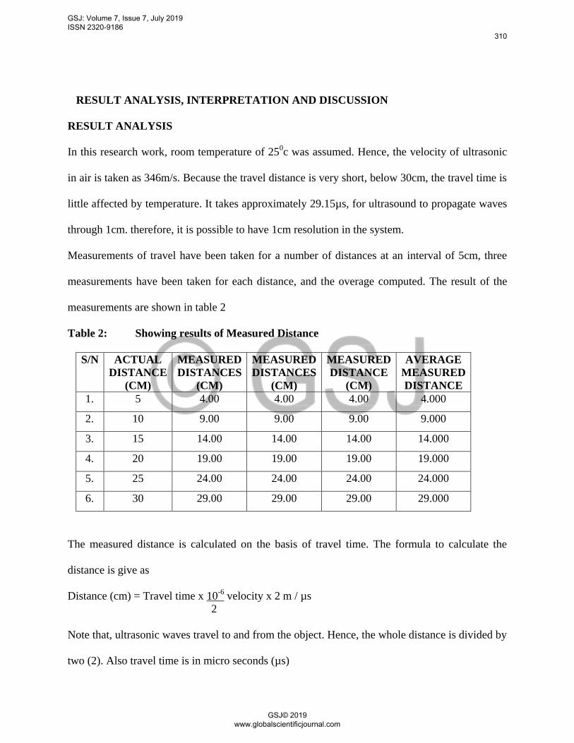
Measurements of travel have been taken for a number of distances at an interval of 5cm, three
measurements have been taken for each distance, and the overage computed. The result of the
measurements are shown in table 2
Table 2: Showing results of Measured Distance
S/N ACTUAL
DISTANCE
(CM)
MEASURED
DISTANCES
(CM)
MEASURED
DISTANCES
(CM)
MEASURED
DISTANCE
(CM)
AVERAGE
MEASURED
DISTANCE
1. 5 4.00 4.00 4.00 4.000
2. 10 9.00 9.00 9.00 9.000
3. 15 14.00 14.00 14.00 14.000
4. 20 19.00 19.00 19.00 19.000
5. 25 24.00 24.00 24.00 24.000
6. 30 29.00 29.00 29.00 29.000
The measured distance is calculated on the basis of travel time. The formula to calculate the
distance is give as
Distance (cm) = Travel time x 10-6
velocity x 2 m / µs
2
Note that, ultrasonic waves travel to and from the object. Hence, the whole distance is divided by
two (2). Also travel time is in micro seconds (µs)
GSJ: Volume 7, Issue 7, July 2019 ISSN 2320-9186
310
GSJ© 2019 www.globalscientificjournal.com
DISCUSSION
From table 2, it can be observed that the constructed ultrasonic distance measurer can be used to
measure distances below 4m, although with less accuracy.
The ultrasonic device is constructed in such a way that the transmitter and receiver are not evenly
matched, resulting in errors in distance measurement. Errors in result also occur due to vibration
from the surrounding and noise, which may interface with the sound waves being propagated.
CONCLUSION
In conclusion, the ultrasonic sensor is developed in order to detects, measure and calculate the
distance of the target object. It was developed to measure distance, ranging from 0.5m to 4m,
using sound waves generated by the sensor in measuring a given range, with high accuracy and
precision. This device measures a given range or distance in a short period of time, and the result
displayed on the LCD.
RECOMMENDATION
Few areas have been recommended for future improvement. These are; range, temperature
control, device portability, software programming are several ideas and modifications that can be
improved the performance of this system in the future to reduce errors
GSJ: Volume 7, Issue 7, July 2019 ISSN 2320-9186
311
GSJ© 2019 www.globalscientificjournal.com
REFERENCES
Anyakoha, M.W. (2013). New School Physics: For Secondary Schools. Africana first publisher,
Revised edition, Pp. 326 – 332, Onitsha
Guenning, F.E, Varlan, M. Eugene, C.E and Dupius, P (1997). Accurate distance measurement
by autonomous ultrasonic system, combining time-of-flight and phase shift method.
Journal of IEEE on Trans. On instrument and measurement, Vol.46, Pp. 1236-1241,
Brussels.
He, H. and Liu, J. (2008). The design of ultrasonic distance measurement system based on
S3C2410.Proceeding of the journal of IEEE: International conference on intelligent
computational technology and automation, Brussels.
Keeler, M. Len, B. and Keith, A. (2012). Journal of Glaciology, International glaciological
society, Vol. 58, Num. 209, Pp. 565 – 568, US.
Ke-yu, L. Chin-Feng, H. Sin-San, H. Ke-Nung, H. and Ming-Shing, Y. (2012). A high resolution
ultrasonic distance measurement system using Vernier Caliper phase meter. Journal of
IEEE instrumentation and measuring society, Vol.61, Pp 2924-2931, Brussels
Li, B. and Libermann, R.C (2007). Indoor Seismology by probing the earth’s interior by using
Sound Velocity measurement at high pressures and temperatures, PNAS, 104(22), 9145-
9150, New York.
Lopera-Gonzalez, L.I Grobekathofert, U and Amft, O. (2014). Novel Stochastic model for
presence detection using ultrasonic ranging sensors. Journal of IEEE, Pp. 155-160,
Brussels.
Noshelsky, L. and Robert, L.B (1997). Electronic devices and circuit theory, 6th
edition, Pp. 822.
Prentice hall, 5th
edition, New York.
Pius, N.O and Anyakoha, M.W. (1987). Senior Secondary Physics. Macmillan Education,
Ibadan.
Sinclair, L.R. and John, D. (2007). Practical Electronic Handbook, 6th
edition, Tokyo, Japan,
Vartanian, H. Jurickson-Rhodes, J. (2013). Providing indoor location, position, or tracking of a
mobile computer using building information. HJ Laboratories, LLC, Pennsylavania.
GSJ: Volume 7, Issue 7, July 2019 ISSN 2320-9186
312
GSJ© 2019 www.globalscientificjournal.com