Embed Size (px)
Citation preview

stormwater solutions / storage / chambers
Construction Guide


Construction Guide
Page 1 ©2016 Prinsco, Inc | 800.992.1725 | www.prinsco.com rev.012916
Table of ContentsIntroduction ..............................................................................................1Material & Equipment Checklist................................................................2 Materials .............................................................................................2 Equipment ..........................................................................................2Handling ...................................................................................................3 Receiving ...........................................................................................3 Unloading ...........................................................................................3 Moving ...............................................................................................3Subgrade and Foundation Preparation ....................................................4 Excavation ..........................................................................................4 Placing Geotextile ..............................................................................4 Placing Bed ........................................................................................5Manifold Assembly ...................................................................................6End Cap and Chamber Assembly ............................................................7 Connecting End Caps to Manifold .....................................................7 For prefabricated end cap/inlet ...................................................7 For on-site end cap/inlet fabrication ...........................................7 Adding Chambers ..............................................................................7 Pre-treatment/Sediment Row ............................................................9Inspection Port Placement .......................................................................9Chamber Backfill Process ......................................................................10 Embedment Stone ...........................................................................10 Initial Backfill ....................................................................................11 Final Backfill .....................................................................................11Table 1 - Backfill Materials ......................................................................12Table 2 - Placement Methods .................................................................13Table 3 - Construction Loading ..............................................................14Notes ......................................................................................................15
IntroductionTo ensure a trouble-free installation, it is essential that the installer is familiar with the minimum requirements specified in this guide. Adherence to this guide is necessary to maintain the structural integrity of the HydroStor Chamber system. In addition, the chamber supplier, chamber installer (site contractor) and the design engineer may meet for a pre-construction meeting to discuss any questions relating to the installation process, and the guidelines herein.

Construction Guide
Page 2 ©2016 Prinsco, Inc | 800.992.1725 | www.prinsco.com rev.012916
Material & Equipment ChecklistMaterials❑ HydroStor chambers and end caps❑ Woven & non-woven geotextiles❑ Manifold pipe, fittings & couplers❑ Acceptable backfill material found in Table 2 on page 13❑ Pre-treatment system❑ Inlet diversion structure for sediment row (optional)❑ PVC pipe & fittings for inspection port (optional)
Equipment❑ Minimum 72 in. (1.8m) forks or straps for unloading chamber pallets
Note: HS180 chamber pallets are 78" x 90" (198 cm x 229 cm), weighing approximately 2,400 lbs. (1,089 kg).HS75 chamber pallets are 52" x 88" (132 cm x 223.5 cm), weighing approximately 2,500 lbs. (1,134 kg).
❑ Reciprocating saw or hole saw for coring holes in end caps/chambers
❑ Approved compaction equipment❑ Excavator to dig trench and place stone and soil backfill❑ Stone conveyor/ lightweight tracked dozer not exceeding 4.5 psi
(31 kPa) to grade backfill❑ Wire cutters❑ Transit/laser level

Construction Guide
Page 3 ©2016 Prinsco, Inc | 800.992.1725 | www.prinsco.com rev.012916
HandlingReceiving
� Visually inspect chambers and end caps for damage.� Ensure accurate quantities.
Unloading� Unload chamber pallets
using forklift with a minimum of 72 in. (1.8 m) forks.
Moving� Use handles on each side of chamber when moving.

Construction Guide
Page 4 ©2016 Prinsco, Inc | 800.992.1725 | www.prinsco.com rev.012916
Subgrade and Foundation PreparationExcavation
� Excavate area according to project plans.� Maintain required clearance around chamber system (see illustration
below for minimum clearance).
If subgrade is wet or unstable, take appropriate measures to correct. Consult design engineer if necessary.
Placing Geotextile� Place an AASHTO M288 Class 2 non-woven 4 oz. or 6 oz.
(136 or 203 g/m2) geotextile on foundation bottom and sidewalls; overlap all seams 24 in. (600 mm).
Construction Guide
Page 5 ©2016 Prinsco, Inc | 800.992.1725 | www.prinsco.com rev.012916
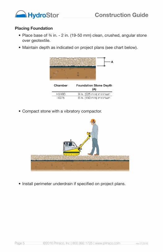
Placing Foundation� Place base of ¾ in. - 2 in. (19-50 mm) clean, crushed, angular stone
over geotextile.� Maintain depth as indicated on project plans (see chart below).
� Compact stone with a vibratory compactor.
� Install perimeter underdrain if specified on project plans.
Construction Guide
Page 6 ©2016 Prinsco, Inc | 800.992.1725 | www.prinsco.com rev.012916
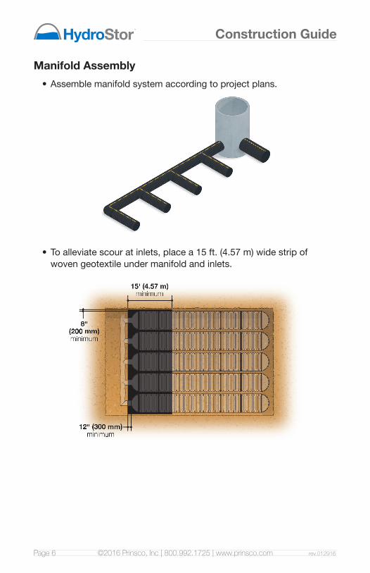
Manifold Assembly� Assemble manifold system according to project plans.
� To alleviate scour at inlets, place a 15 ft. (4.57 m) wide strip of woven geotextile under manifold and inlets.

Construction Guide
Page 7 ©2016 Prinsco, Inc | 800.992.1725 | www.prinsco.com rev.012916
End Cap and Chamber AssemblyConnecting End Caps to Manifold
For prefabricated end cap/inlet:
� Connect to manifold using split coupler.
For on-site end cap/inlet fabrication:
� Core an opening in end cap the same size as inlet pipe.
� Insert inlet pipe a minimum of 12 in. (300 mm) into end cap.
� Cover any voids greater than ¾ in. (19 mm) with non-woven geotextile.
� Connect to manifold using split coupler.
Adding Chambers
Note overlap and orientation instructions labeled on chamber ends (see illustration on next page).
� Place first corrugation of chamber under end cap, following direction arrow on chamber end.
� Fasten end caps with four evenly spaced screws.

Construction Guide
Page 8 ©2016 Prinsco, Inc | 800.992.1725 | www.prinsco.com rev.012916
� Assemble each row by placing following chamber on top of previous chamber.
� Maintain required minimum row spacing (see chart below).
� Row assembly should not exceed reach of backfill placement equipment.
� Terminate each row with end cap.

Construction Guide
Page 9 ©2016 Prinsco, Inc | 800.992.1725 | www.prinsco.com rev.012916
Pre-treatment/Sediment Row
Prinsco recommends pretreatment of stormwater runoff using a Prinsco Stormwater Quality Unit and/or a sediment row. Review design plan for installation.
Inspection Port Placement� Identify chamber(s) to be fitted with inspection port(s).� Cut a 4 in. (100 mm) diameter opening at appropriate location(s).� Build inspection port(s) using a tap tee connection to join Sch 40 or
SDR 35 PVC pipe and fittings.

Construction Guide
Page 10 ©2016 Prinsco, Inc | 800.992.1725 | www.prinsco.com rev.012916
Chamber Backfill ProcessEmbedment Stone
No construction equipment shall be situated atop of the chamber system.
� Use ¾ in.-2 in. (19-50 mm) particle size, washed, crushed, angular stone.
� Carefully deposit embedment stone along chamber centerline using excavator or stone shooter.
� Stone height between rows and sidewalls should not differ by more than 12 in. (300 mm).
� Embedment stone minimum cover height: 12 in. (300 mm) for HS180, 6 in. (150 mm) for HS75.

Construction Guide
Page 11 ©2016 Prinsco, Inc | 800.992.1725 | www.prinsco.com rev.012916
Wheel and Roller Loads Not Allowed. Minimum of 12" (300 mm) of cover for HS180 chambers and 6" (150 mm) of cover for HS75 chambers before a skid loader or small dozer is allowed over chambers.
� Finalize grading with tracked dozer with ground pressure less than 4.5 psi. (31 kPa), running dozer parallel to rows at all times.
� Cover with AASHTO M288 Class 2 non-woven 4 or 6 oz. (136 or 203 g/m2) geotextile; overlap all seams 24 in. (600 mm).
Initial Backfill
� Use excavator positioned off bed to place initial backfill.� Begin compaction to cover height of 23.5 in. (590 mm) for HS180,
and 18 in. (450 mm) for HS75.� Compaction equipment to travel parallel with chamber rows (refer to
Table 3 on page 14 for loads).
Final Backfill� Refer to design plans for final backfill specifications.

Construction Guide
Page 12 ©2016 Prinsco, Inc | 800.992.1725 | www.prinsco.com rev.012916
Table 1 - Backfill MaterialsFill Material Location Material Description AASHTO M43 Designation
[D] Final Backfill - Fill material for Layer D starts at the top of the C layer to the bottom of the pavement or to the finished grade of an unpaved surface. The pavement subbase may be part of the final backfill.
Any backfill which provides adequate subgrade for the project per the engineer's plans. Plans shall indicate subgrade requirements.
N/A
[C] Initial Backfill - Material for layer C starts at the top of the embedment zone (layer B) and continues to 24" (600 mm) above the top of the chamber for the HS180 and 18" (450 mm) for the HS75. The pavement subbase may be part of the initial backfill layer.
Well graded granular material, <35% fines.
AASHTO M45 A-1, A-2, A-3
or AASHTO M43
3, 357, 4, 467, 5, 56, 57, 6, 67, 68, 7, 78, 8, 89, 9, 10
[B] Embedment Stone - Embedment stone will surround the chambers and extends from the top of the foundation stone (layer A) to the bottom of the geotextile layer.
3/4" to 2" (19-50 mm) washed, crushed,
angular stone.
AASHTO M43 3, 357, 4, 467, 5, 56, 57
[A] Foundation Stone - Foundation Stone extends from the sub grade to the foot of the chambers.
3/4" to 2" (19-50 mm) washed, crushed,
angular stone.
AASHTO M43 3, 357, 4, 467, 5, 56, 57

Construction Guide
Page 13 ©2016 Prinsco, Inc | 800.992.1725 | www.prinsco.com rev.012916
Table 2 - Placement MethodsFill Material Location Placement Methods /
RestrictionsHS180 Compaction
RequirementsHS75 Compaction
Requirements
[D] Final Backfill A variety of placement methods may be used. All construction loads must not exceed the limits in Table 3, page
14.
Subgrade will be placed and compacted
to the requirements as shown on the site
plans.
Subgrade will be placed and compacted
to the requirements as shown on the site
plans.
[C] Initial Backfill Use of an excavator positioned off bed is recommended.
Small excavators and small dozers may be allowed based on the information in Table 3,
page 14.
Compaction will not begin until a minimum
of 24" (600 mm) of material is placed
over the chambers. Additional layers shall
be compacted in 12" (300 mm) lifts to a minimum of 95% standard proctor
density for well graded material.
Compaction will not begin until a minimum
of 12" (300 mm) of material is placed
over the chambers. Additional layers
shall be compacted in 6" (150 mm) lifts to a minimum of 95% standard proctor
density for well graded material. Roller gross
vehicles are not to exceed 12,000
lbs. (53.38 kN) and dynamic force not to exceed 20,000 lbs.
(88.96 kN).
[B] Embedment Stone
No equipment is allowed on bare chambers. Use
excavator or stone conveyor positioned
off bed to evenly place the backfill around
and on top of all of the chambers.
No compaction required.
No compaction required
[A] Foundation Stone Placement with a variety of equipment is acceptable to provide a stable, level base.
Placed in 9" (225 mm) lifts and compacted
with a vibratory roller.
Placed in 6" (150 mm) lifts and compacted
with a vibratory roller.

Construction Guide
Page 14 ©2016 Prinsco, Inc | 800.992.1725 | www.prinsco.com rev.012916
Table 3 - Construction LoadingMaterial Location
Fill Depth Above
Chambers in. (mm)
Max Allowable Wheels Loads
Max Allowable Track Loads Max Allowable
Roller Loads
Max Axle
Load For Trucks
lbs. (kN)
Max Wheel Load For
Trucks lbs. (kN)
Track Width in.
(mm)
Max Ground Pressurepsf (kPa)
Max Drum Weight
Dynamic Force
lbs. (kN)
[D] Final Fill Material
36" (900) Compacted
32,000 (142)
16,000 (71)
12" (300)18" (450)24" (600)30" (750)36" (900)
3420 (163.75)2350 (112.52)1850 (88.58)1510 (72.30)1310 (62.72)
38,000 (169)
[C] Initial Fill
24" (600) Compacted
32,000(142)
16,000(71)
12" (300)18" (450)24" (600)30" (750)36" (900)
2480 (118.74)1770 (84.75)1430 (68.47)1210 (57.94)1070 (51.23)
20,000 (89)
24" (600) Dumped
24,000(107)
12,000(53)
12" (300)18" (450)24" (600)30" (750)36" (900)
2245 (107.49)1625 (77.81)1325 (63.44)1135 (54.34)1010 (48.36)
16,000 (71) for HS180
20,000 (89) for HS75
Gross weight of roller not to exceed 12,000 lbs. (5,443 kg)
18" (450) 24,000(107)
12,000(53)
12" (300)18" (450)24" (600)30" (750)
2010 (96.24)1480 (70.86)1220 (58.41)1060 (50.75)
5,000 (22) for HS180
20,000 (89) for HS75
Gross weight of roller not to exceed 12,000 lbs. (5,443 kg)
[B] Embedment
Zone
12" (300) N/A N/A
12" (300) 1100 (52.67) for HS180 1540 (73.74) for HS75
N/A
18" (450) 715 (34.23) for HS180 1190 (56.98) for HS75
24" (600) 660 (31.60) for HS180 1010 (48.36) for HS75
30" (750) 580 (27.77) for HS180 910 (43.57) for HS75
6" (150) N/A N/A
12" (300) N/A for HS180 1070 (51.23) for HS75
N/A18" (450) N/A for HS180 900
(43.09) for HS75
24" (600) N/A for HS180 800 (38.30) for HS75
30" (750) N/A for HS180 760 (36.39) for HS75
N/A = Not Allowed

Construction Guide
Page 15 ©2016 Prinsco, Inc | 800.992.1725 | www.prinsco.com rev.012916
Notes:
1. 36 in. (900 mm) of stabilized cover is required over chambers before full dump trucks may travel and dump on chamber system.
2. To calculate the ground pressures for small tracked dozers, determine the vehicle operating weight and divide by total ground contact area for both tracks. The ground pressures for tracked excavators will be greater due to the loaded bucket weight and boom extension.
3. Allowable track loads based on the vehicle travel only. Excavators shall not operate on chamber beds until a minimum of 3 feet (900 mm) of cover has been placed over the chambers.
4. Mini excavators (<8,000 lbs. [3,629 kg]) can be used with at least 12 in. (300 mm) of stone cover over the chambers and are limited based on the ground pressures shown in Table 3 on page 14.
5. During paving operations, loaded dump trucks at minimum cover heights may be necessary. Precautions must be taken to ensure that rutting of the sub base layer does not occur, that minimum cover heights are met and that adequate compaction of the sub base is maintained. Refer to Table 3 on page 14 or contact your local Prinsco Representative for more information about allowable axle loads.
6. Construction materials, excess equipment or spoil piles should not be positioned over a HydroStor chamber system. For equipment not listed in Table 3 on page 14, contact your Local Prinsco Representative for more information.
7. Compaction of the initial backfill layer should not begin until the minimum cover over the chambers has been reached (minimum 23.5 in. [590 mm] for HS180, and minimum 18 in. [450 mm] for HS75).

Notes:

Notes:

* Assuming 40% void volume of backfill with 9" (225mm) foundation & 11.5"(290mm) cover for HS180 and 6" (150mm) bedding & 6" (150mm) cover for HS75
75 ft3 (2.12m3)/chamber29.7" (754mm)
51" (1295mm)
87.1" (2212mm)
84.9" (2156mm)
70 lbs (31.75kg)
33PolypropyleneInjection MoldingIntegrated HandlesMeets or Exceeds
6" (150mm) minimum6" (150mm) minimum6" (150mm)
51" (1295mm)
12" (300mm)
29.7" (754mm)
18" (450mm)
8' (2.44m)
180ft3(5.1m3)/chamber45.5" (1156mm)
77.8" (1976mm)
88.7" (2253mm)
85.3" (2166mm)
127 lbs (57.6kg)
17Polypropylene
Injection MoldingIntegrated HandleMeets or Exceeds
11.5" (290mm) minimum9" (225mm) minimum
8" (200mm)
77.8" (1976mm)
12" (300mm)
45.5" (1156mm)
23.5" (590mm)
8' (2.44m)
Installed Storage Capacity*HeightWidth
Unit LengthInstalled Length
WeightChambers/Pallet
MaterialMfg. Process
Special FeaturesASTM Standards
Backfill Above ChamberBedding
Chamber SpacingChamber Width
Backfill At Edge Of SystemChamber HeightMinimum Cover
Maximum Burial Depth
800.992.1725PRINSCO.COMYour Resources. One Stop. Any Device.
Prinsco.com/HydroStor-ResourcesFor more HydroStor™ resources, visit