Embed Size (px)
Citation preview
Construction InformaticsBauhaus University
A Flexible Model for Incorporating Construction Product Data into Building Information Models
A thesis submitted toBauhaus University in Weimar
For the degree ofDr.-Ing.
by
Mohamed Magdy NOUR BA., M.Sc.
Examiners:Bauhaus University, Weimar, Germany:1. Prof. Dr.-Ing. Karl Beucke2. Prof. Dr.-Ing. Hans Wihelm Alfen3. J. Prof. Dr.-Ing. Berthold Firmenich
Loughborough University, England:4- Prof. Dr. Chimay Anumba
Date of Defense: 14th of March, 2006.

© Copyright 2005 M.M. Nour

Declaration
No portion of the work referred to in this thesis has been submitted in support of anapplication for another degree or qualification of this or any other University oflearning.
iii

Acknowledgments
I would like to thank my supervisors; Professor Karl Beucke for his invaluableguidance, sincere advice and encouragement throughout this thesis and ProfessorBerthold Firmenich for his invaluable support that enabled putting the theory of thiswork into a practical IT implementation.
I would like also to thank my colleagues Martin Freundt and Timo Heinrich whohelped me with their advice and the material they teach at the Bauhaus University.
I am very thankful to Mr. Jens-Uwe Wagner, Mrs. Mechtild Bieber, our network andsoftware administrators and Ms Christa Diez the secretary of the department for theirsupport during the past three years.
I would like also to express my gratitude for the DAAD that enabled me to conductsuch kind of research at the Bauhaus University in Germany. Last but not least, Iwould like to thank the ProSTEP AG company in Germany and the EPM Technologycompany in Norway for granting me an EXPRESS/STEP implementation course thathelped me in using such technologies in this research work.
iv

Dedication
To my parents and grand parents,
v
Abstract
When considering the integration and interoperability between AEC-FM software applications
and construction products' data, it is essential to investigate the state-of-the-art and conduct an
extensive review in the literature of both Building Information Models and electronic product
catalogues. It was found that there are many reasons and key-barriers that hinder the developed
solutions from being implemented.
Among the reasons that are attributed to the failure of many previous research projects to achieve
this integration aim are the proprietary developments of CAD vendors, the fragmented nature of
construction product data i.e. commercial and technical data, the prefabrication versus on-site
production, marketing strategies and brand-naming, the referencing of a product to the data of
its constituents, availability of life-cycle data in a single point in time where it is needed all over
the whole life-cycle of the product itself, taxonomy problems, the inability to extract search
parameters from the building information model to participate in the conduction of parametric
searches. Finally and most important is keeping the product data in the building information
model consistent and up-to-date. Hence, it was found that there is a great potential for
construction product data to be integrated to building information models by electronic means in
a dynamic and extensible manner that prevents the model from getting obsolete.
The study has managed to establish a solution concept that links continually updated and
extensible life-cycle product data to a software independent building information model (IFC) all
over the life span of the product itself. As a result, the solution concept has managed to reach a
reliable building information model that is capable of overcoming the majority of the above
mentioned barriers. In the meantime, the solution is capable of referencing, retrieving, updating,
and merging product data at any point in time. A distributed network application that represents
all the involved parties in the construction product value chain is simulated by real software tools
to demonstrate the proof of concept of this research work.
Keywords: Construction Product Data, IFC, BIMs (Building Information Models)
vi
List of Contents
Dedication.........................................................................................................vAbstract............................................................................................................viList of Contents...............................................................................................viiList of Figures...................................................................................................xiList of Tables..................................................................................................xiv
Chapter 1Introduction.....................................................................1
1.1 Introduction.............................................................................................11.2 Aim and Objectives..................................................................................1
1.2.1 Aim...........................................................................................................................11.2.2 Objectives................................................................................................................2
1.3 Methodology...........................................................................................21.4 Scope.......................................................................................................31.5 The Structure of the Thesis....................................................................4
Chapter 2Literature Review.............................................................7
2.1 Introduction...........................................................................................72.2 The state-of-the-art of on-line product catalogues................................8
2.2.1 Commercial product catalogue vendors................................................................82.2.2 Independent initiatives from major CAD vendors..............................................11
2.2.2.1 Architectural Desktop....................................................................................................122.2.2.2 ArchiCAD......................................................................................................................12
2.2.3 Research Projects.................................................................................................142.2.3.1 ARROW..........................................................................................................................152.2.3.2 CONNET (CONNstruction information service NETwork) ..........................................172.2.3.3 Eindhoven University of Technology.............................................................................172.2.3.4 GEN Projects..................................................................................................................172.2.3.5 Georgia Institute Of Technology....................................................................................182.2.3.6 Loughborough University..............................................................................................192.2.3.7 University of Edinburgh.................................................................................................192.2.3.8 GAEB.............................................................................................................................202.2.3.9 RINET -Building Product Database..............................................................................222.2.3.10 eConstruct....................................................................................................................23
2.3 Conclusion............................................................................................242.3.1 A central Database................................................................................................252.3.2 Communication in XML......................................................................................262.3.3 Access on the web and client user interface........................................................262.3.4 Taxonomy and Standards....................................................................................262.3.5 Linking to CAD.....................................................................................................27
vii
Chapter 3The Statement of the Problem........................................28
3.1 Introduction..........................................................................................283.2 The Value and Supply Chains..............................................................28
3.2.1 Information Middlemen......................................................................................283.2.2 Branding...............................................................................................................303.2.3 Manufacturers and Suppliers...............................................................................313.2.4 Prefabrication versus on Site Production............................................................32
3.3 Life Cycle Information and Updates.....................................................323.4 Search Mechanisms..............................................................................33
3.4.1 Text based searches .............................................................................................333.4.2 Searches based on Classifications and Standards................................................333.4.3 Parametric Searches.............................................................................................343.4.4 Retrieving Information using GUIDs..................................................................34
3.5 A Building Information Model..............................................................353.6 Conclusion and Guidelines for the Research Work..............................36
3.6.1 Conclusion............................................................................................................363.6.2 Guidelines............................................................................................................37
Chapter 4Model of Proposed Solution ...........................................39
4.1 Introduction..........................................................................................394.2 OIP Specifications................................................................................39
4.2.1 Producer...............................................................................................................404.2.2 Format and Design of OIP....................................................................................414.2.3 Degree of Granularity..........................................................................................434.2.4 An OIP Organization............................................................................................43
4.2.4.1 OIP Layering System .....................................................................................................434.2.5 OIP Implementation............................................................................................46
4.2.5.1 The Basic Concept..........................................................................................................474.2.5.2 Scenarios........................................................................................................................494.2.5.3 Example..........................................................................................................................51
4.2.6 Limitations...........................................................................................................524.3 Conclusion............................................................................................53
Chapter 5Prototype Implementation.............................................55
5.1 Introduction..........................................................................................555.2 Manufacturer Side................................................................................595.3 OIP Organisation..................................................................................59
5.3.1 The OIP Object Oriented Model...........................................................................605.3.2 The OIP Database relational Model.....................................................................62
viii
5.3.3 Mapping the OIP Object Oriented model to a relational Model.........................665.4 Portal Database.....................................................................................67
5.4.1 Web Server............................................................................................................705.5 Client Side..............................................................................................71
5.5.1 Parsing STEP ISO 10303 – P21 Files....................................................................725.5.1.1 Analysis of a STEP file....................................................................................................735.5.1.2 The development of the Parser.......................................................................................75
5.5.2 IFC Interpreter.....................................................................................................765.5.2.1 EXPRESS........................................................................................................................765.5.2.2 STEP Standard Data Access Interface (SDAI)..............................................................825.5.2.3 Mapping EXPRESS Data Types.....................................................................................845.5.2.4 IFC2x Interpreter...........................................................................................................95
5.5.3 Visualisation.......................................................................................................1065.5.3.1 Project Tree View.........................................................................................................1065.5.3.2 CAD View......................................................................................................................1135.5.3.3 STEP View ...................................................................................................................127
5.5.4 Operations on the IFC Model.............................................................................1285.5.4.1 Instantiation.................................................................................................................1305.5.4.2 Updates........................................................................................................................1325.5.4.3 Deletion........................................................................................................................1335.5.4.4 Exporting the modified STEP ISO 10303 – P21...........................................................133
5.6 Merging and Updating of Construction Product Data in the IFC model. ....................................................................................................................136
5.6.1 Conduction of Parametric Searches....................................................................1365.6.2 Merging Imported Product Data .......................................................................1375.6.3 Updating Product Information..........................................................................139
5.7 Work flow Management Aspects.........................................................1405.8 Summary & Conclusions.....................................................................141
Chapter 6Conclusions and recommendations for further research.........................................................................................144
6.1 Conclusions.........................................................................................1446.2 Review of chapters..............................................................................1476.3 Recommendations for further studies and concept development......148
6.3.1 Further studies....................................................................................................1486.3.2 Concept development.........................................................................................149
References.....................................................................................................150
Appendices Appendix A1: An Example of a STEP ISO 10303-P21 file..................................................157 Appendix A2: A jjdoc output of the STEP_Parser.jj grammar file for the NON-TERMIANLS. .......................................................................................................................159
ix

Appendix A3: IAI Definition of the the PsetDoorCommon................................................160 Appendix A4: The Java Code for the Property Set PsetDoorCommon...............................161 Appendix A5: An example of an exported STEP-P21 file from the author's software.......164 Appendix B: The use of a Drag and Drop solution over the Internet for the merging andtransfer of data. ...................................................................................................................169 Appendix “C”.......................................................................................................................170 Zusammenfassung der Arbeit......................................................................................171
x
List of FiguresFigure 2.1 Searching e-Catalogues by Product Name 10Figure 2.2 Manufacturers PDF Catalogues 10Figure 2.3 Manufacturer's PDF file 10Figure 2.4 Supplier's Details 11Figure 2.5 i-drop technology example 12Figure 2.6 a GDL 3D script sample 13Figure 2.7 An example of GDL data types 13Figure 2.8 The Structure of the Arrow System, (Newnham et al 1998) 16Figure 2.9 Performance based Searches (P: Product, I:Performance Indicator, S:Standard/Code),Source: (Jain et al 1998) 18Figure 2.10 A java window showing the links to Web pages, Source: (Coyne et al 2003) 19Figure 2.11 A schedule of Components as produced by ArchiCAD 20Figure 2.12 Information Flow in GAEB DA2000-XML Standard, (Diaz, 2004.) 21Figure 2.13 RINET'sConceptual Framework, Source: (RINET 2000) 22Figure 2.14 Main Constituents of bcXML, Source: (Tolman et al 2001) 23Figure 3.1 T:Transaction between I: Intermediaries, P:Producer and C: Customer, ,(Sarker et al1995) 29Figure 4.1 The Structure of the OIP Identifier 41Figure 4.2 The OIP formulation of the OIP and constituents referencing 42Figure 4.3 The layering System of the OIP data structure 44Figure 4.4 An example of the OIP data structure 45Figure 4.5 EXPRESS-G diagram showing the OIP Structure 45Figure 4.6 An EXPRESS-G diagram showing OIP resources 46Figure 4.7 The mathematical relations between the OIP identifiers 47Figure 4.8 The mapping between objects in the IFC model and OIPs 48Figure 4.9 The OIP Implementation 49Figure 4.10 The Instantiation of OIP in CAD 50Figure 4.11 IFC door Panel and Lining 51Figure 4.12 Selection of a door from a portal website 52Figure 5.1 A Map View of the OIP System 55Figure 5.2 Manufacturer's Remote GUI (UI3) 59Figure 5.3 The UML diagram of the OIP construction products 60Figure 5.4 The UML diagram of the OIP kernel relations 61Figure 5.5 The UML Diagram of the OIP resources 62Figure 5.6 The tables of the OIP relational model 63Figure 5.7 The OIP table in the relational model 63Figure 5.8 OIP relational model 64Figure 5.9 The Representation of container classes in the relational model 65Figure 5.10 The OIP_Door table in the Oip relational model 65Figure 5.11 The representation of the property sets in the OIP relational model 65Figure 5.12 The OIP Organisation search GUI (UI1) 66Figure 5.13 The definition of a value interval for parametric searches 67Figure 5.14 The Supplier's registration at the Portal Website 68Figure 5.15 Options at portal website registration 68
xi
Figure 5.16Suppliers and Products 68Figure 5.17 The runtime object oriented model of the portal website database 68Figure 5.18 The design of the commercial OIP relational model 69Figure 5.19 The inclusion of extra commercial properties 69Figure 5.20 The commercial attributes of a product 70Figure 5.21 The Portal Web server GUI (UI2) 71Figure 5.22 Constituents of a STEP file, (Nour 2004) 74Figure 5.23 The Analysis of the STEP file, (Nour 2004) 75Figure 5.24 The representation of the parsed STEP ISO 10303-P21 file in the form of a threedimensional array, (Nour 2004) 75Figure 5.25 EXPRESS ISO 10303-P11 data types 78Figure 5.26 A UML diagram for Mapping IFC Enumerations to Java 89Figure 5.27 An EXPRESS-G diagram for the enumerations, IFC2x Model Implementation Guide(2002) 89Figure 5.28 A UML diagram showing the inheritance tree of an IfcWallStandardCase 93Figure 5.29 Java packages representing IFC EXPRESS schemata 95Figure 5.30UML diagram showing the separation between the IFC model and its implementation,(Nour et al, 2005) 96Figure 5.31 IFC2x Interpreter's flow chart 105Figure 5.32 IFC Project Tree View with CAD 106Figure 5.33 Combined View of CAD & STEP 107Figure 5.34 The IFC model project hierarchy and space arrangement, IFC2x Model ImplementationGuide 2002 107Figure 5.35 Mandatory and optional levels of the IFC project tree 108Figure 5.36 Layout of the example given above 108Figure 5.37 The decomposition of the IFC Spatial Structure, IFC2x Model Implementation Guide2002 109Figure 5.38 IfcRelAggregates 110Figure 5.39 The Project Tree Viewer flow chart 110Figure 5.40 A snap shot showing the tree-view GUI 111Figure 5.41 An EXPRESS-G Diagram showing the product placement in the coordinate system 115Figure 5.42 A UML Diagram for the IfcAxis2Placement, (Nour 2005) 115Figure 5.43 A snap shot of the Client User Interface 121Figure 5.44 A snap shot from ArchiCAD showing the IFC model 122Figure 5.45.Selection of elements on the CAD View 122Figure 5.46 A snap shot from ArchiCAD showing vertical section 1-1 of the IFC model 123Figure 5.47 A snap shot from ArchiCAD showing the floor at level 0.0 123Figure 5.48 The CAD view of the Software development showing the floor at level (3.05) & itsconstituents 123Figure 5.49 The CAD view of the Software development showing the floor at level (0.0) & itsconstituents 123Figure 5.50 A snap shot showing the rotation of the ground floor by 45 degrees anti-clockwise 124Figure 5.51 A zoomed in snap shot showing the details of connection between walls, openings &doors 124Figure 5.52 A tree view of the Java package related to the CAD view 125Figure 5.53 The relations and cardinalities between classes in the cad package 126
xii
Figure 5.54 A snap shot of the STEP view 127Figure 5.55 An overall view of the operations on the IFC model, (Nour et al 2005) 129Figure 5.56 An EXPRESS-G diagram showing the relation between properties & constructionproducts through the definition relationship, (Nour er al 2005) 130Figure 5.57 Instantiation of PsetDoorCommon 132Figure 5.58 Reflection of update on the Project Tree 133Figure 5.59 Explicit Updates 133Figure 5.60 Writing STEP ISO 10303 P-21, (Nour et al 2005) 134Figure 5.61 A Snap shot from ArchiCAD showing the Import results 135Figure 5.62 A Snap Shot from ArchiCAD showing the newly instantiated data 135Figure 5.63 A Snap Shot from ADT showing the import results 136Figure 5.64 A snap shot of the console output showing the query object's ragged array of technicalparameters 137Figure 5.65 The wrapping of transferred objects over the Internet 138Figure 5.66 The GUI for merging and updating construction product information to the IFC model
139Figure 5.67 Checking for updates 140
xiii

List of TablesTable 2.1 Commercial e-Catalogs 10Table 2.2 Features of Research Projects 25Table 5.1 Example of OIP product Data for a simple steel door 58Table 5.2 Example of OIP Material Data for steel 58Table 5.3 Mapping EXPRESS to STEP & Java, (Nour et al 2005) 85
xiv
Chapter 6 Prototype Implementation
Chapter 1
1.1 Introduction
This thesis is concerned with linking continually updated life-cycle product data to a software
independent building information model (IFC) all over the life span of the construction product
itself. The work resulted in a flexible and reliable building information model that is capable of
referencing, retrieving, updating and merging product data from its information sources
throughout the product's value chain.
The thesis as a whole aims at designing a new solution concept that is based on the existence of
construction product data, side by side in parallel to the Building Information Model has been
established. The data can be retrieved by parametric searches as well as global unique
identification throughout the product's overall life-cycle. The work takes into consideration the
characteristics and peculiarities of the construction products' value chain. Furthermore, the
product's information model is developed step by step with the product itself, as if it were one of
its components. The concept distributes and allocates the responsibility of building the product
information model among the parties that create and own the information themselves. The
concept is proved and simulated by a real open network distributed platform application that
represents all the parties involved in the construction product's value chain.
1.2 Aim and Objectives
1.2.1 Aim
● “Linking continually updated extensible life-cycle construction product data to software
independent Building Information Models, throughout the life-cycle of the product.”
1
Chapter 6 Prototype Implementation
1.2.2 Objectives
1- Viewing the literature and the state-of-the-art of linking construction product data to
Building Information Models.
2- Identification of problems and key barriers that hinder the integration of continually
updated product data with Building Information Models.
3- Putting forward some guidelines that can help changing the current status of lack of
integrity of product data with Building Information Models.
4- Designing a new concept that overcomes the shortcomings of the previous research
efforts according to the previously developed guidelines. In addition to taking into
consideration the peculiarities of the construction product's value chain and its marketing
strategies.
5- Identification of relevant IT technologies that can serve achieving the aim and
objectives of this research work.
6- Providing a proof of concept through a real software development.
7- Independence from any proprietary commercial software applications or Building
Information Models.
1.3 Methodology
The research work begins with a view of the literature and the current state-of-the-art of the
2
Chapter 6 Prototype Implementation
relation between electronic product catalogues and Building Information Models with the aim of
providing a clear definition of the problem and putting forward some guidelines to be followed
for the development of any solution concept.
The research views some of the marketing strategies that influence the construction products
physical market place as well as the virtual market space (Internet), together with the
peculiarities of the construction products' value chain.
In the light of the literature review and the analysis of the construction products' value chain, a
new concept is suggested to overcome the identified key barriers and problems.
Finally, a proof of concept is provided through an open distributed software platform, that is
independent from any proprietary software application to link construction product data with a
software independent Building Information Model (IFC).
1.4 Scope
The developed solution is proved by implementing a longitudinal section throughout the
suggested model. The software development covers construction products only, where as the
main abstract concept is extensible and includes other aspects such as construction services.
Some resources such as equipment, labour and so forth are considered to be out of the scope of
this work. Moreover, an example of a wall, an opening and a door are only implemented in the
Building Information model. However, the same concept can be applied for the rest of the spatial
elements, e.g. slabs, columns or windows. In the meantime, taxonomy and ontology problems of
construction products are not covered in this work.
It is also worth mentioning that the author is not a computer science specialist or an IT expert.
The author has depended partially on attending courses for the basics of Java programming,
CAD development, EXPRESS (ISO 10303-P11), EXPRESS-X (ISO 10303-P14) and STEP (ISO
3
Chapter 6 Prototype Implementation
10303 P-21) and partially on self learning skills. This proves that the technologies are not difficult
to learn and that they are well documented.
1.5 The Structure of the Thesis
The thesis consists of two main parts. Part I- chapters 2,3,4 – is a view of the literature and the
state-of-the-art of electronic product catalogues, an identification of key barriers and problems
that prevent the integrity between product data and Building Information Models as well as an
analysis to the construction product's value chain and marketing strategies and finally a design of
a new concept for a solution that tries to overcome the barriers that were identified in the
previous stages.
Part II- chapter 5 – provides a proof of concept to the designed solution. It simulates all the
parties that are involved in the construction product value chain according to the solution's
concept. It also includes a set of developed software tools that are capable of carrying out
different processes on the IFC model. Among these process are mapping, merging and updating
of product data to the IFC model.
Chapter 2- “Literature Review”, comprises the state-of-the-art of the linking between electronic
product catalogues and Building Information Models on the scale of commercial product
catalogue vendors, initiatives from major CAD vendors and finally independent research
projects.
Chapter 3- “The Statement of the Problem”, provides an analysis of the value and supply chains
of the construction products and investigates the roles of marketing strategies and information
middlemen in the value and supply chains. It also discusses the peculiarities of the construction
products with a special emphasis on the prefabrication versus on site fabrication. Moreover, It
discusses the need for life-cycle information and the different search mechanisms that are used
for searching for construction products on the Internet. It ends with a discussion about the
4
Chapter 6 Prototype Implementation
integration of product data with Building Information Models together with putting forward
some guidelines that are used in the development of the solution concept.
Chapter 4- “Model of Proposed Solution”, introduces a new concept called OIP (Object
Information Packs) as a suggested solution. It begins by defining the concept, allocating the
responsibilities of the production of such information packs and then moves to the technical
definition of the data management system and its structure. The chapter provides a discussion of
the basic concepts, examples and scenarios of use.
Chapter 5- “Prototype Implementation”, provides a proof of the solution concept provided in
chapter 4. It is a direct implementation to the information model that is defined in the previous
chapter. It makes use of the IFC2x model as a software independent Building Information Model.
It simulates the roles of suppliers, manufacturers and clients (users) in real life scenarios. It
provides database management systems, software tools that provide functionalities for mapping,
merging and updating information inside the IFC model. Furthermore, these tools enable the
specification of product parameters in addition to the extraction of query parameters from the
CAD/IFC model. Moreover, they enable the conduction of parametric searches and monitoring
the existence of any new updates to the products' data.
Chapter 6- “Conclusions and Recommendations for Further Research”, presents the main
conclusions of the whole study and points out some areas for further research. Furthermore, it
puts forward some guidelines for the development of the solution concept that has been
suggested throughout this study.
Appendix A1: Is an example of a STEP ISO 10303-P21 file that shows the main components of a
STEP-P21 file and their functionalities.
Appendix A2: Is a “jj” doc output of the grammar of the developed STEP parser.
Appendix A3: Is the IAI definition of the PsetDoorCommon property set
5

Chapter 6 Prototype Implementation
Appendix A4: Is the Java Code for the property set PsetDoorCommon
Appendix A5: Is an example of an exported STEP-P21 file from the author's software.
Appendix B: Is a UML diagram that shows the use of a Drag and Drop solution over the
Internet for the mapping, merging and the transfer of data.
Appendix C: Is a CD-ROM that contains the Java coding, Databases, testing IFC/CAD models,
and video demonstrations for the prototype development.
6
Chapter 6 Prototype Implementation
Chapter 2
Literature Review
2.1 Introduction
The aim of this research work is to try to keep BIMs (Building Information Models) up-to-date
and capable of providing accurate information about their construction products without being
limited to its original information content. This is envisaged to be achieved by making an on-line
source of life cycle multidisciplinary information available for any information need that might
arise to any application using the model. The latter extends the activities of the model beyond its
information content and in the meantime does not overburden the model with information that
is not needed or used at a certain stage in the life cycle of the product. Moreover it makes
information updates for dynamic properties such as the current commercial and business aspects
available on-line for the model, i.e. It prevents the model form getting obsolete.
An example of this is a simple door. Its geometry is defined by CAD, an energy simulation
programme needs to know its thermal transmittance coefficient, a cost estimating tool needs to
know its up-to-date price, a contractor needs to know its availability at a certain point in time and
later the facility manager needs to know the specifications or the name of the supplier of a certain
spare part of the door.
It is obvious that architects or any other practitioners working on a project that contains
thousands of elements would not have the resources to model each element in the project. They
are most probably paid for the production of printed drawings and documents rather than
models. The problem is even worse when we consider the fact that these models could be project
specific and may not be reused in a product library for similar projects. This approach would
7
Chapter 6 Prototype Implementation
most probably go beyond any approach for return on investment employed. Hence, it is a task
that would be best undertaken by manufacturers and suppliers, where most of the modelling
information is usually available in their product catalogues. This directs the research work
towards studying previous research that is done in the area of electronic product catalogues and
on-line product libraries.
2.2 The state-of-the-art of on-line product catalogues
By researching the area of electronic product catalogues, it was found that the main efforts could
be categorized into three main categories:
1- Commercial product catalogue vendors.
2- Independent initiatives from major CAD vendors.
3- Research projects ranging from individual researchers through to large-scale
European and international projects.
2.2.1 Commercial product catalogue vendors
The majority of commercial product catalogues vendors have developed their own national on-
line systems that are text based1, where they are searched according to keywords (names of
products, suppliers or manufacturers) or local classifications systems and standards. The user is
usually able to navigate through categories of the searched product or the catalogue of a certain
manufacturer or supplier. The user can also browse through the multimedia representation of the
product and try to get relevant information about the product.(Timm and RoseWitz 1998) In
most of the cases the information is delivered in the form of a PDF document that is extracted
from the originally paper-based catalogue, where product information is presented in the form of
text and pictures. Researchers like (Amor et al 2004) have the view that the majority of electronic
catalogues, even today, have duplicated the paper paradigm of the original paper based
catalogues, and as a result, there is an inevitable need for human interpretation and transcription
1 Example: HTML and PDF files
8
Chapter 6 Prototype Implementation
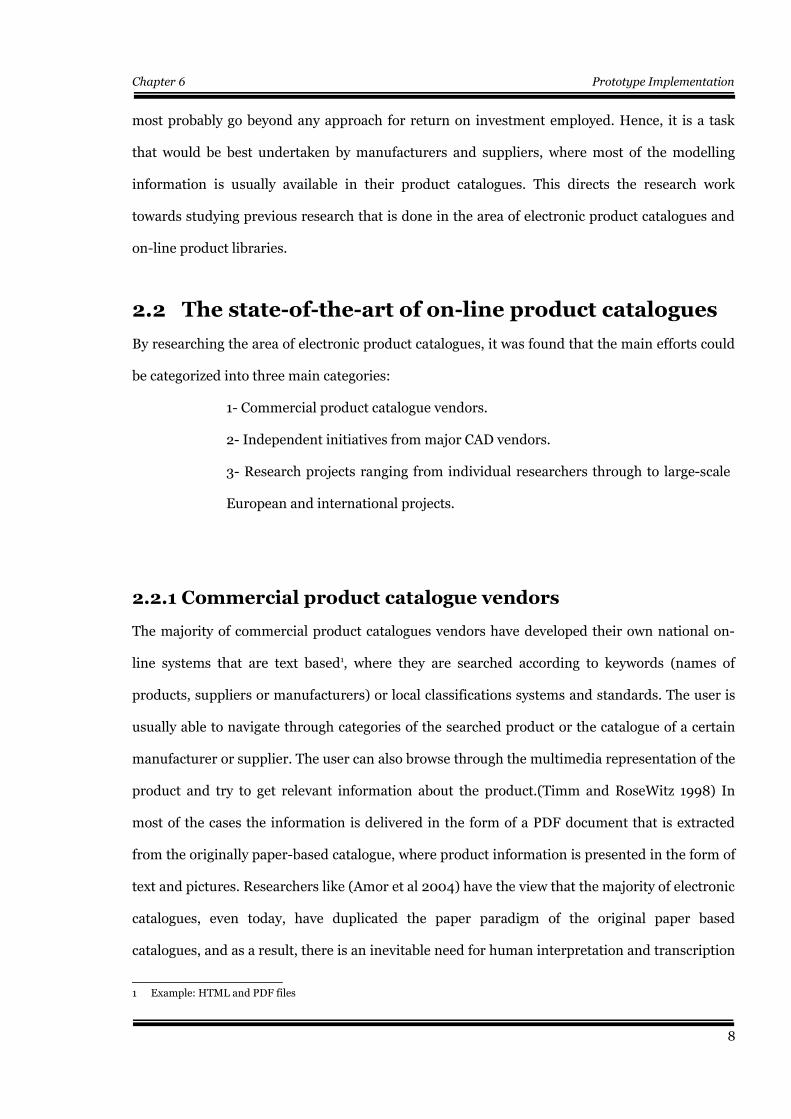
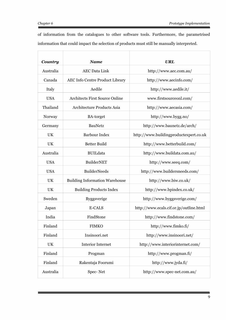
of information from the catalogues to other software tools. Furthermore, the parametrised
information that could impact the selection of products must still be manually interpreted.
Country Name URL
Australia AEC Data Link http://www.aec.com.au/
Canada AEC Info Centre Product Library http://www.aecinfo.com/
Italy Aedile http://www.aedile.it/
USA Architects First Source Online www.firstsourceonl.com/
Thailand Architecture Products Asia http://www.aecasia.com/
Norway BA-torget http://www.bygg.no/
Germany BauNetz http://www.baunetz.de/arch/
UK Barbour Index http://www.buildingproductexpert.co.uk
UK Better Build http://www.betterbuild.com/
Australia BUILdata http://www.buildata.com.au/
USA BuilderNET http://www.seeq.com/
USA BuilderNeeds http://www.buildersneeds.com/
UK Building Information Warehouse http://www.biw.co.uk/
UK Building Products Index http://www.bpindex.co.uk/
Sweden Byggsverige http://www.byggsverige.com/
Japan E-CALS http://www.ecals.cif.or.jp/outline.html
India FindStone http://www.findstone.com/
Finland FIMKO http://www.fimko.fi/
Finland Insinoori.net http://www.insinoori.net/
UK Interior Internet http://www.interiorinternet.com/
Finland Progman http://www.progman.fi/
Finland Rakentaja Foorumi http://www.jyda.fi/
Australia Spec- Net http://www.spec-net.com.au/
9
Chapter 6 Prototype Implementation
Country Name URL
USA Sweets http://sweets.construction.com/
Switzerland Swiss Internet Baubank http://www.dewadata.ch/baubank/
UK Virtual- Engineer http://www.virtual-engineer.net/
Table 2.1 Commercial e-Catalogs
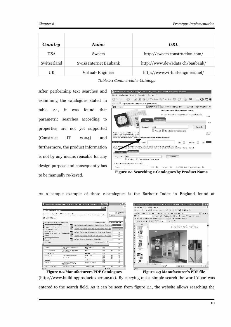
After performing text searches and
examining the catalogues stated in
table 2.1, it was found that
parametric searches according to
properties are not yet supported
(Construct IT 2004) and
furthermore, the product information
is not by any means reusable for any
design purpose and consequently has
to be manually re-keyed.
As a sample example of these e-catalogues is the Barbour Index in England found at
(http://www.buildingproductexpert.ac.uk). By carrying out a simple search the word 'door' was
entered to the search field. As it can be seen from figure 2.1, the website allows searching the
10
Figure 2.1 Searching e-Catalogues by Product Name
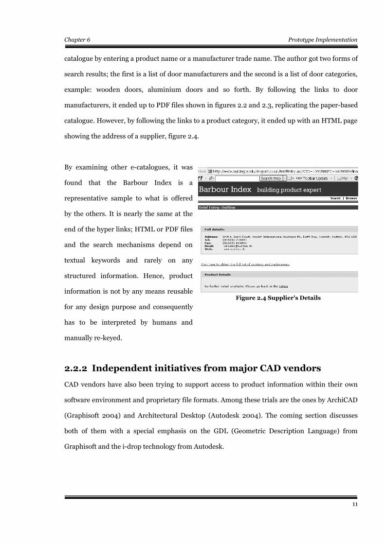
Figure 2.2 Manufacturers PDF Catalogues Figure 2.3 Manufacturer's PDF file
Chapter 6 Prototype Implementation
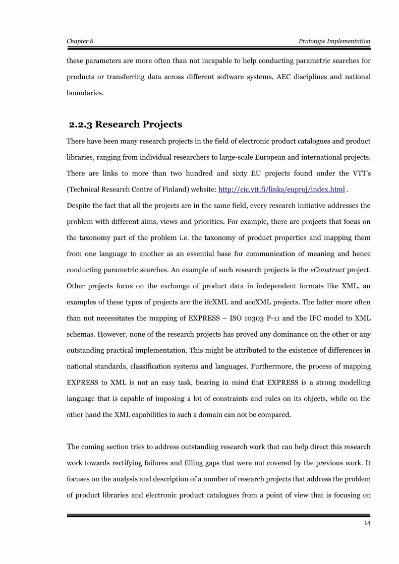
catalogue by entering a product name or a manufacturer trade name. The author got two forms of
search results; the first is a list of door manufacturers and the second is a list of door categories,
example: wooden doors, aluminium doors and so forth. By following the links to door
manufacturers, it ended up to PDF files shown in figures 2.2 and 2.3, replicating the paper-based
catalogue. However, by following the links to a product category, it ended up with an HTML page
showing the address of a supplier, figure 2.4.
By examining other e-catalogues, it was
found that the Barbour Index is a
representative sample to what is offered
by the others. It is nearly the same at the
end of the hyper links; HTML or PDF files
and the search mechanisms depend on
textual keywords and rarely on any
structured information. Hence, product
information is not by any means reusable
for any design purpose and consequently
has to be interpreted by humans and
manually re-keyed.
2.2.2 Independent initiatives from major CAD vendors
CAD vendors have also been trying to support access to product information within their own
software environment and proprietary file formats. Among these trials are the ones by ArchiCAD
(Graphisoft 2004) and Architectural Desktop (Autodesk 2004). The coming section discusses
both of them with a special emphasis on the GDL (Geometric Description Language) from
Graphisoft and the i-drop technology from Autodesk.
11
Figure 2.4 Supplier's Details
Chapter 6 Prototype Implementation
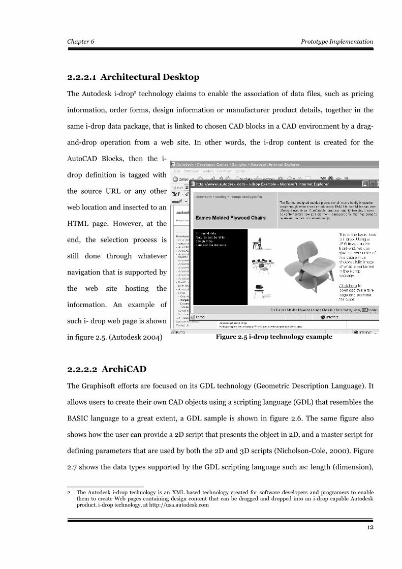
2.2.2.1 Architectural Desktop
The Autodesk i-drop2 technology claims to enable the association of data files, such as pricing
information, order forms, design information or manufacturer product details, together in the
same i-drop data package, that is linked to chosen CAD blocks in a CAD environment by a drag-
and-drop operation from a web site. In other words, the i-drop content is created for the
AutoCAD Blocks, then the i-
drop definition is tagged with
the source URL or any other
web location and inserted to an
HTML page. However, at the
end, the selection process is
still done through whatever
navigation that is supported by
the web site hosting the
information. An example of
such i- drop web page is shown
in figure 2.5. (Autodesk 2004)
2.2.2.2 ArchiCAD
The Graphisoft efforts are focused on its GDL technology (Geometric Description Language). It
allows users to create their own CAD objects using a scripting language (GDL) that resembles the
BASIC language to a great extent, a GDL sample is shown in figure 2.6. The same figure also
shows how the user can provide a 2D script that presents the object in 2D, and a master script for
defining parameters that are used by both the 2D and 3D scripts (Nicholson-Cole, 2000). Figure
2.7 shows the data types supported by the GDL scripting language such as: length (dimension),
2 The Autodesk i-drop technology is an XML based technology created for software developers and programers to enablethem to create Web pages containing design content that can be dragged and dropped into an i-drop capable Autodeskproduct. i-drop technology, at http://usa.autodesk.com
12
Figure 2.5 i-drop technology example

Chapter 6 Prototype Implementation
angular measure, natural numbers,
Integer, Boolean, String, Material,
Line Types, Hatching Patterns, Line
Colour and so forth.
Electronic product catalogues like
GDL central
(http://www.gdlcentral.com/) or
ArchiForum
(http://www.archiforum.de/) offer
their products in a drag and drop
environment to ArchiCAD users
and through an add-on adaptor to Autodesk's Architectural Desktop and other major CAD
software users.
However, it should be mentioned that, the
GDL object models work best inside a
Graphisoft Environment and have
inevitable loss of information when
transferred to other CAD environments.
Nevertheless, GDL is a proprietary
extension of Graphisoft and is not
independent from its environment. The
author has also discovered the fact that the
GDL parameters are not contained in other
exports formats like IFC ( tried with
ArchiCAD version 7.0, student version and IFC2x add-on). Furthermore, the capability of users
to define their own object parameters, without following any standards, leads to the fact that
13
Figure 2.6 a GDL 3D script sample
Figure 2.7 An example of GDL data types
Chapter 6 Prototype Implementation
these parameters are more often than not incapable to help conducting parametric searches for
products or transferring data across different software systems, AEC disciplines and national
boundaries.
2.2.3 Research Projects
There have been many research projects in the field of electronic product catalogues and product
libraries, ranging from individual researchers to large-scale European and international projects.
There are links to more than two hundred and sixty EU projects found under the VTT's
(Technical Research Centre of Finland) website: http://cic.vtt.fi/links/euproj/index.html .
Despite the fact that all the projects are in the same field, every research initiative addresses the
problem with different aims, views and priorities. For example, there are projects that focus on
the taxonomy part of the problem i.e. the taxonomy of product properties and mapping them
from one language to another as an essential base for communication of meaning and hence
conducting parametric searches. An example of such research projects is the eConstruct project.
Other projects focus on the exchange of product data in independent formats like XML, an
examples of these types of projects are the ifcXML and aecXML projects. The latter more often
than not necessitates the mapping of EXPRESS – ISO 10303 P-11 and the IFC model to XML
schemas. However, none of the research projects has proved any dominance on the other or any
outstanding practical implementation. This might be attributed to the existence of differences in
national standards, classification systems and languages. Furthermore, the process of mapping
EXPRESS to XML is not an easy task, bearing in mind that EXPRESS is a strong modelling
language that is capable of imposing a lot of constraints and rules on its objects, while on the
other hand the XML capabilities in such a domain can not be compared.
The coming section tries to address outstanding research work that can help direct this research
work towards rectifying failures and filling gaps that were not covered by the previous work. It
focuses on the analysis and description of a number of research projects that address the problem
of product libraries and electronic product catalogues from a point of view that is focusing on
14
Chapter 6 Prototype Implementation
both linking product data to BIMs and conducting parametric searches.
2.2.3.1 ARROW
ARROW is a three years UK initiative project funded by the PiT programme. Its main aim is to
retrieve manufacturer's product information from the so called virtual warehouses. It claims that
it allows manufacturers to describe the attributes of their own products and link them to a virtual
warehouse that is able to handle structured as well as unstructured (free text) information from
suppliers and manufacturers. Furthermore, manufacturers should be able to upload any kind of
electronic documentation that is related to the product. In the meantime, responses to queries
should be in a form that can be used by CAD systems. It should be mentioned that the ARROW
model is built entirely upon the IFC model, where one hundred and eighty tables were created in
Microsoft Access database. These tables act as a mapping of the IFC model, in addition to some
extensions to cover the full range of product information.
The process of mapping ARROW's object oriented model into a relational database, has
highlighted many of the problems of representation of object oriented data structures in a
relational database technology. The problems were attributed to the lack of polymorphic
capabilities in a relational database as well as the representation of aggregate types ( lists, sets,
bags, arrays, etc.). Furthermore, SQL queries that are needed to retrieve records from the
database usually consist of extremely long WHERE clauses and more often than not arises the
need for multiple sub-queries.
15
Chapter 6 Prototype Implementation
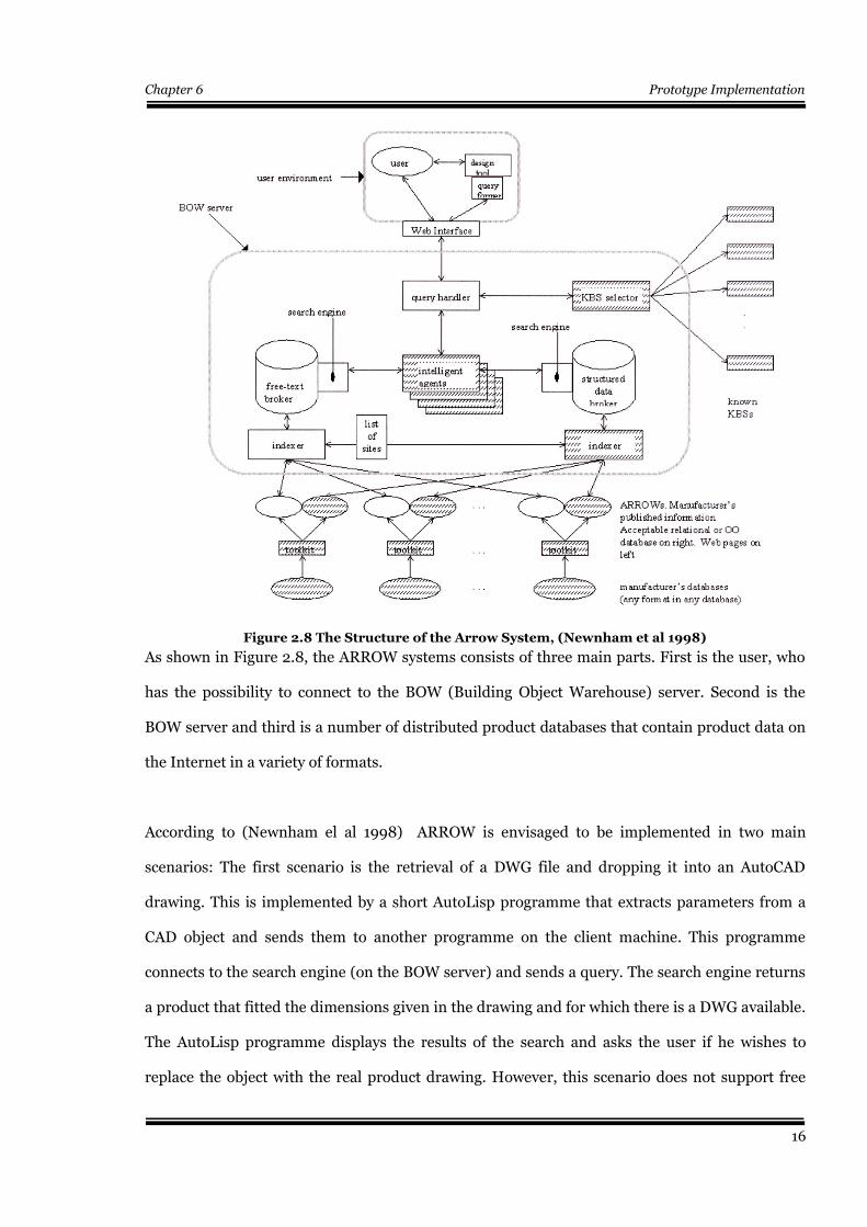
As shown in Figure 2.8, the ARROW systems consists of three main parts. First is the user, who
has the possibility to connect to the BOW (Building Object Warehouse) server. Second is the
BOW server and third is a number of distributed product databases that contain product data on
the Internet in a variety of formats.
According to (Newnham el al 1998) ARROW is envisaged to be implemented in two main
scenarios: The first scenario is the retrieval of a DWG file and dropping it into an AutoCAD
drawing. This is implemented by a short AutoLisp programme that extracts parameters from a
CAD object and sends them to another programme on the client machine. This programme
connects to the search engine (on the BOW server) and sends a query. The search engine returns
a product that fitted the dimensions given in the drawing and for which there is a DWG available.
The AutoLisp programme displays the results of the search and asks the user if he wishes to
replace the object with the real product drawing. However, this scenario does not support free
16
Figure 2.8 The Structure of the Arrow System, (Newnham et al 1998)
Chapter 6 Prototype Implementation
text searches .The second scenario uses a web browser interface to demonstrate the blending of
the text and structured database searches; where the user selects from a list of products and then
is introduced to a list of searchable fields representing the properties of that product.
2.2.3.2 CONNET (CONNstruction information service NETwork)
The CONNET project (www.connet.org) is a one year EU funded project, that tried to achieve the
following objectives:
• Enabling queries to be passed between European national systems to provide a
European-wide identification service.
• A data model that helps catalogue producers migrate the current paper-equivalent on-
line systems to complex attribute driven services.
• Providing a service-based infrastructure for basic support to new catalogue
producers. (Amor et al 2000).
2.2.3.3 Eindhoven University of Technology
Research work at the Eindhoven University has tried to achieve a feature based modelling
approach for product representation and dynamic specifications of differentiating features for
products, in addition to the management of product information across firms and projects. (Van
Leeuwen and Fridqvist 2002).
2.2.3.4 GEN Projects
PROCAT-GEN (Cook et al 1999, Faux et al 1998) and GENIAL (Debras 2000, Faux et al 1998) are
three years EU funded projects. They tried to develop an open XML-based data model for
product classification and attributes of products. Further more, it provides manufacturer’s and
suppliers with side tools to enable searching for products within product catalogues. The right to
carry out information updates is also granted to particular users.
17
Chapter 6 Prototype Implementation
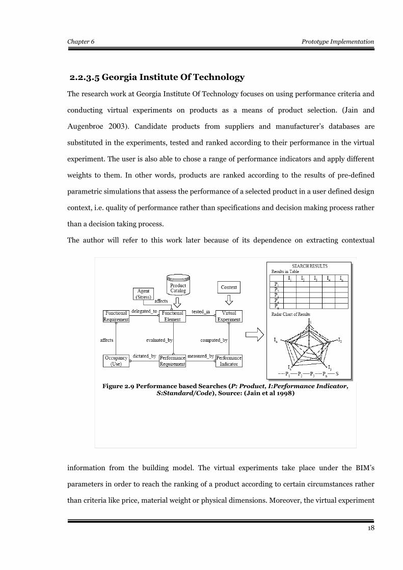
2.2.3.5 Georgia Institute Of Technology
The research work at Georgia Institute Of Technology focuses on using performance criteria and
conducting virtual experiments on products as a means of product selection. (Jain and
Augenbroe 2003). Candidate products from suppliers and manufacturer’s databases are
substituted in the experiments, tested and ranked according to their performance in the virtual
experiment. The user is also able to chose a range of performance indicators and apply different
weights to them. In other words, products are ranked according to the results of pre-defined
parametric simulations that assess the performance of a selected product in a user defined design
context, i.e. quality of performance rather than specifications and decision making process rather
than a decision taking process.
The author will refer to this work later because of its dependence on extracting contextual
information from the building model. The virtual experiments take place under the BIM’s
parameters in order to reach the ranking of a product according to certain circumstances rather
than criteria like price, material weight or physical dimensions. Moreover, the virtual experiment
18
Figure 2.9 Performance based Searches (P: Product, I:Performance Indicator,S:Standard/Code), Source: (Jain et al 1998)
Chapter 6 Prototype Implementation
is in itself a parametrized building model that can be instantiated at any time with values of the
current design context and parameters of the candidate product.(Jain et al 2003)
Figure 2.9 shows relations between various performance indicators, the virtual experiment, the
context of the model and the product catalogue . The virtual experiment extracts its attributes
from the BIM context and a set of performance indicators are defined, upon which the ranking of
catalogue candidates takes place. The right-hand-side figure shows how the results can be
tabulated and ranked on a radar chart.
2.2.3.6 Loughborough University
The research work at Loughborough University is focused on an agent based approach to
gathering and querying product data from XML-based repositories, also an algorithm for
interpreting standard data in PDF documents, in addition to an agent-based automated purchase
negotiation system were developed. (Obonyo et al 2001)
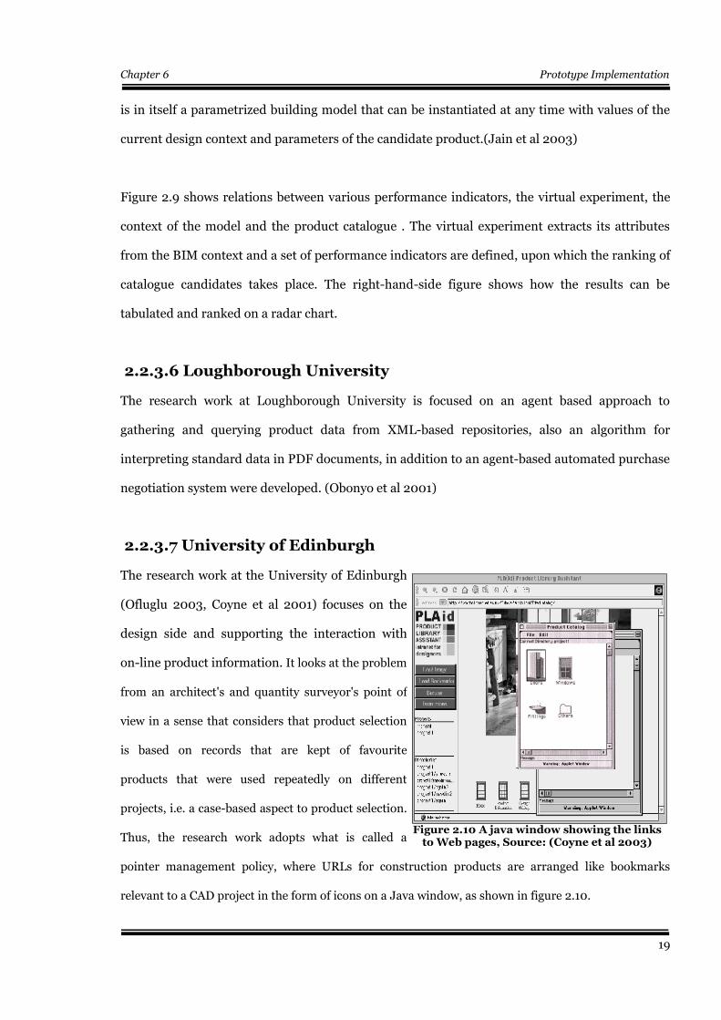
2.2.3.7 University of Edinburgh
The research work at the University of Edinburgh
(Ofluglu 2003, Coyne et al 2001) focuses on the
design side and supporting the interaction with
on-line product information. It looks at the problem
from an architect's and quantity surveyor's point of
view in a sense that considers that product selection
is based on records that are kept of favourite
products that were used repeatedly on different
projects, i.e. a case-based aspect to product selection.
Thus, the research work adopts what is called a
pointer management policy, where URLs for construction products are arranged like bookmarks
relevant to a CAD project in the form of icons on a Java window, as shown in figure 2.10.
19
Figure 2.10 A java window showing the linksto Web pages, Source: (Coyne et al 2003)
Chapter 6 Prototype Implementation
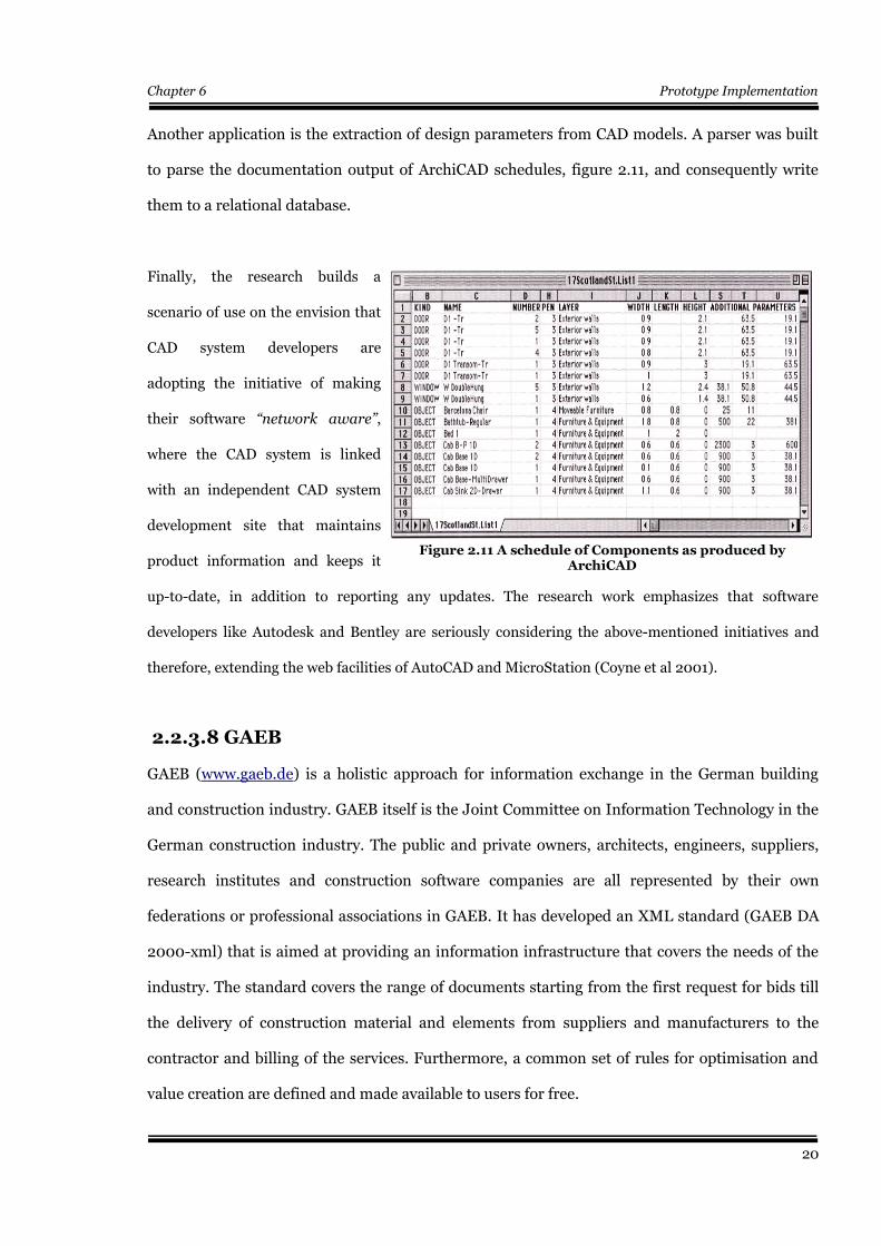
Another application is the extraction of design parameters from CAD models. A parser was built
to parse the documentation output of ArchiCAD schedules, figure 2.11, and consequently write
them to a relational database.
Finally, the research builds a
scenario of use on the envision that
CAD system developers are
adopting the initiative of making
their software “network aware”,
where the CAD system is linked
with an independent CAD system
development site that maintains
product information and keeps it
up-to-date, in addition to reporting any updates. The research work emphasizes that software
developers like Autodesk and Bentley are seriously considering the above-mentioned initiatives and
therefore, extending the web facilities of AutoCAD and MicroStation (Coyne et al 2001).
2.2.3.8 GAEB
GAEB (www.gaeb.de) is a holistic approach for information exchange in the German building
and construction industry. GAEB itself is the Joint Committee on Information Technology in the
German construction industry. The public and private owners, architects, engineers, suppliers,
research institutes and construction software companies are all represented by their own
federations or professional associations in GAEB. It has developed an XML standard (GAEB DA
2000-xml) that is aimed at providing an information infrastructure that covers the needs of the
industry. The standard covers the range of documents starting from the first request for bids till
the delivery of construction material and elements from suppliers and manufacturers to the
contractor and billing of the services. Furthermore, a common set of rules for optimisation and
value creation are defined and made available to users for free.
20
Figure 2.11 A schedule of Components as produced byArchiCAD
Chapter 6 Prototype Implementation
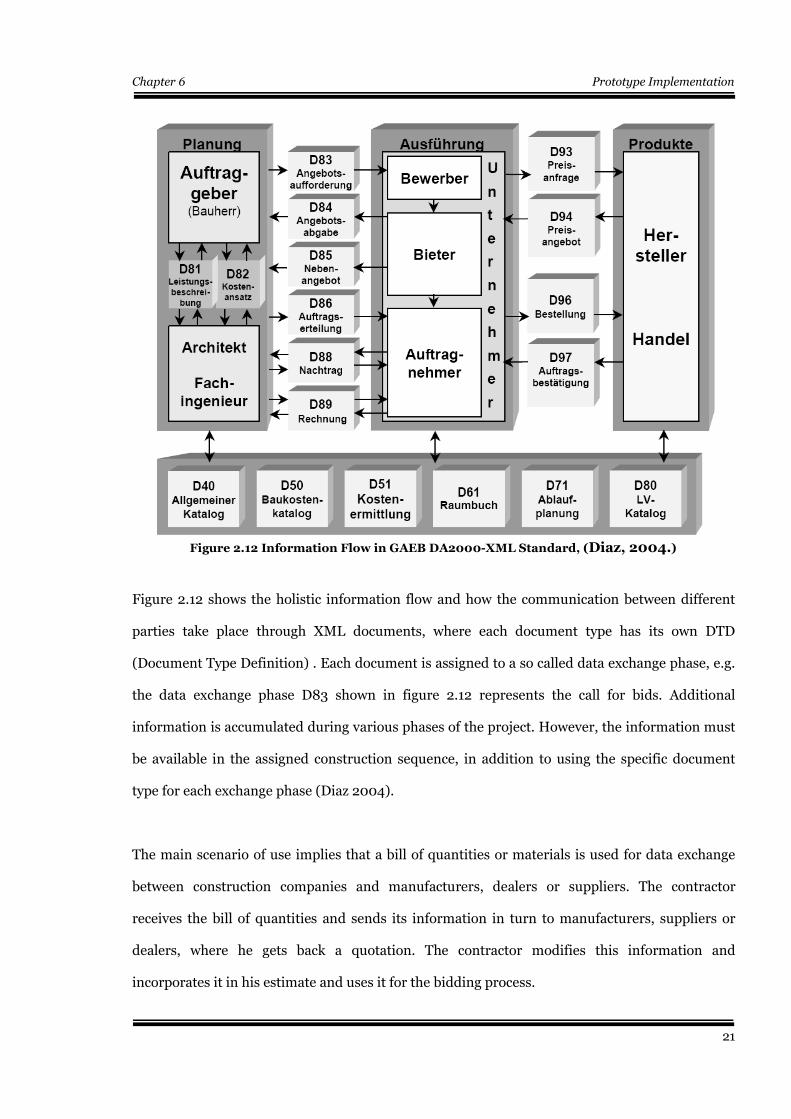
Figure 2.12 shows the holistic information flow and how the communication between different
parties take place through XML documents, where each document type has its own DTD
(Document Type Definition) . Each document is assigned to a so called data exchange phase, e.g.
the data exchange phase D83 shown in figure 2.12 represents the call for bids. Additional
information is accumulated during various phases of the project. However, the information must
be available in the assigned construction sequence, in addition to using the specific document
type for each exchange phase (Diaz 2004).
The main scenario of use implies that a bill of quantities or materials is used for data exchange
between construction companies and manufacturers, dealers or suppliers. The contractor
receives the bill of quantities and sends its information in turn to manufacturers, suppliers or
dealers, where he gets back a quotation. The contractor modifies this information and
incorporates it in his estimate and uses it for the bidding process.
21
Figure 2.12 Information Flow in GAEB DA2000-XML Standard, (Diaz, 2004.)
Chapter 6 Prototype Implementation
However, it should be mentioned that the information exchange process in all stages can not be
successful without the existence of an exchange standard that is capable of being handled by
various software and hardware platforms, in addition to providing a common language for
construction information exchange. The latter was considered to be the main challenge for
GAEB. Hence, the standardisation was done on two levels: First is on product catalogue
structures and second is on product classification. At the catalogue structure level the BMEcat-
format (www.bmecat.org) has been used. Consequently, any supplier must comply his catalogue
with the BMEcat standard. On the other hand, on the classification level, in order to avoid each
supplier using his own vocabularies and structures in describing his product, the (eCl@ss 2004)
standard was implemented.
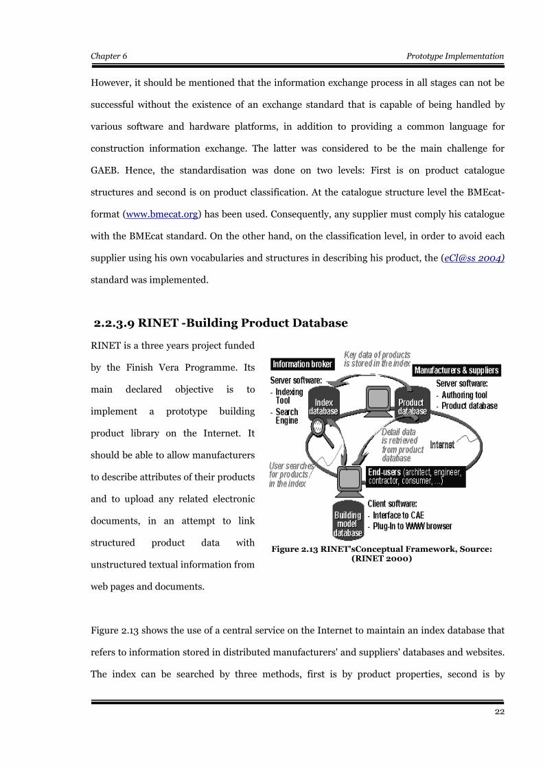
2.2.3.9 RINET -Building Product Database
RINET is a three years project funded
by the Finish Vera Programme. Its
main declared objective is to
implement a prototype building
product library on the Internet. It
should be able to allow manufacturers
to describe attributes of their products
and to upload any related electronic
documents, in an attempt to link
structured product data with
unstructured textual information from
web pages and documents.
Figure 2.13 shows the use of a central service on the Internet to maintain an index database that
refers to information stored in distributed manufacturers' and suppliers' databases and websites.
The index can be searched by three methods, first is by product properties, second is by
22
Figure 2.13 RINET'sConceptual Framework, Source:(RINET 2000)
Chapter 6 Prototype Implementation
classification and third is by free text keyword searches. The project claims also that it is capable
of reusing parametric product data through an interface to CAE. However, it should be
mentioned that the client interface is built on the Finish Building 90 classification system.
(Building 90 1999)
2.2.3.10 eConstruct
The aim of the EU IST-10303 “eConstruct”
project (www.econstruct.org) was
developing an XML vocabulary and
grammar for the European BC (Building and
Construction) industry, with focus on the
communication of meaning by trying to
overcome barriers that stem from
differences in languages and national
classification systems, i.e. the things that
define the BC semantics. One partner of the
project is the Dutch Specification Institute
STABU (http://www.stabu.nl) which has an
active role in the ISO/DPAS 12006-3 (“A
frame work for object oriented exchange in BC”). STABU was considered to be the corner stone
for developing the bcXML compliant taxonomy (the Lexicon).
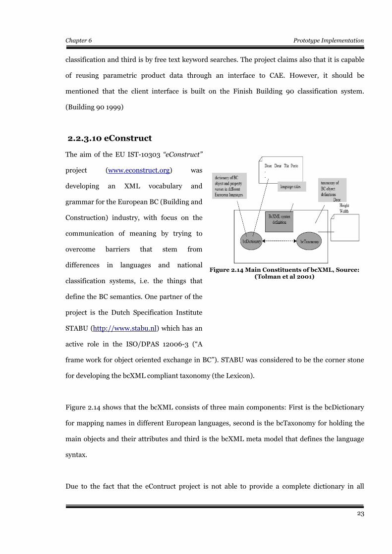
Figure 2.14 shows that the bcXML consists of three main components: First is the bcDictionary
for mapping names in different European languages, second is the bcTaxonomy for holding the
main objects and their attributes and third is the bcXML meta model that defines the language
syntax.
Due to the fact that the eContruct project is not able to provide a complete dictionary in all
23
Figure 2.14 Main Constituents of bcXML, Source:(Tolman et al 2001)
Chapter 6 Prototype Implementation
European languages, a limited set of words were developed in a limited set of languages in an
open system that can be extended by others with additional words and translations. Hence, the
aim was directed towards encouraging everybody to use bcXML compliant taxonomies so long as
the produced XML documents conform to the bcXML rules (schema).
Finally, a set of developed prototype applications that use bcXML were developed. They depend
on formulating queries from clients to suppliers in XML that complies with the bcXML schema.
On the other hand responses to queries are returned in the same information format, i.e. clients
can make use of the information by parsing and interpreting the XML file according to the
definitions in the bcXML schema.
2.3 Conclusion
This chapter has examined forms of product information , selection mechanisms, queries to
product information and forms of query results in different commercial, major CAD vendors
initiatives and different scale research projects.
Commercial product catalogue vendors have proven to be oriented towards a free text HTML or
PDF content that is searched by keywords. Moreover, the content is not reusable for design
purposes and is not in a format that can be mapped to a building information model.
At the CAD vendors level the i-drop technology from Autodesk and GDL technology from
Graphisoft were examined. It was found that the product selection process is still done through
whatever navigation that is supported by the web site hosting the information. Furthermore, i-
drop and GDL models are proprietary commercial developments and the transfer of any of them
to a foreign environment results in inevitable loss of information and functionalities. On the
other hand the freedom of structuring data about product properties without following any
standards has led to the fact that these parameters are unable to communicate their meaning
across different software applications and thus, incapable of conducting parametric searches .
24
Chapter 6 Prototype Implementation
Project Central
Search
Engine
MXL
Communica-
tion
Web
access
Client
User
Interface
Taxonomy
Standard
Linking
to CAD
ARROW ● ● ● ●
CONNET ● ●
Eindhoven ● ●
GEN ● ●
Georgia
Loughborough ● ● ● ●
Edinburgh ● ● ● ● ●
GAEB ● ● ●
RINET ● ● ●
eConstruct ● ● ● ●
Table 2.2 Features of Research Projects
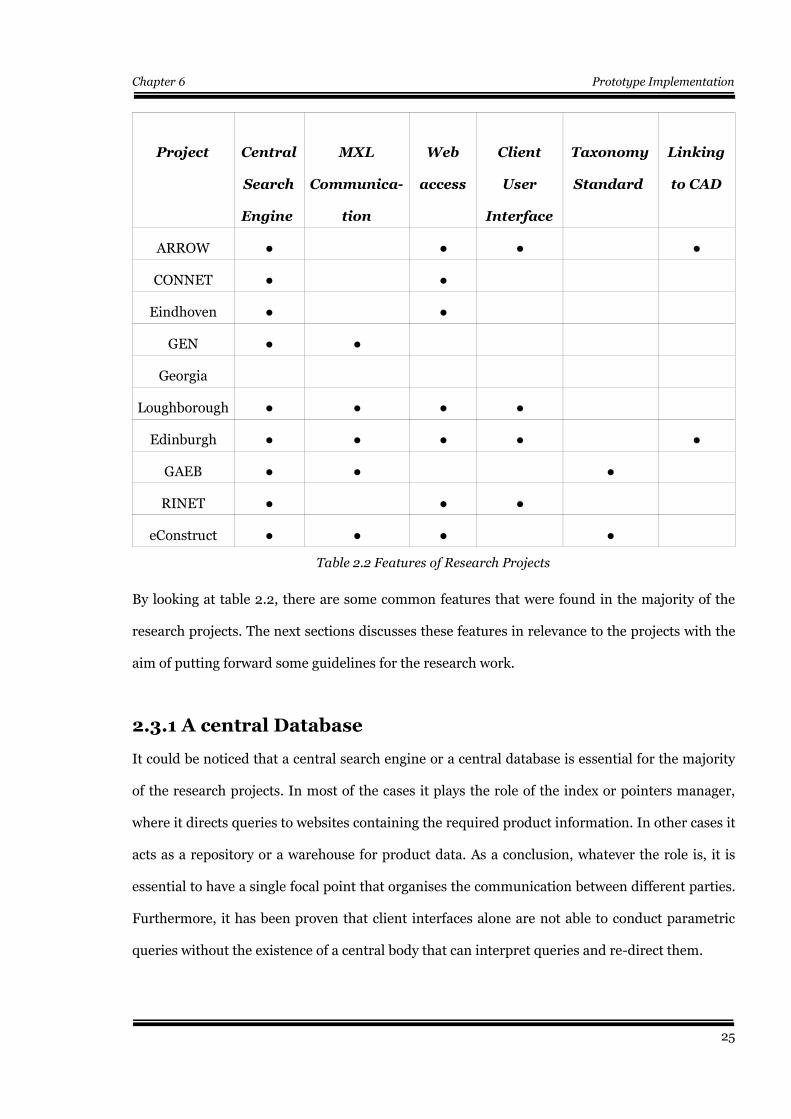
By looking at table 2.2, there are some common features that were found in the majority of the
research projects. The next sections discusses these features in relevance to the projects with the
aim of putting forward some guidelines for the research work.
2.3.1 A central Database
It could be noticed that a central search engine or a central database is essential for the majority
of the research projects. In most of the cases it plays the role of the index or pointers manager,
where it directs queries to websites containing the required product information. In other cases it
acts as a repository or a warehouse for product data. As a conclusion, whatever the role is, it is
essential to have a single focal point that organises the communication between different parties.
Furthermore, it has been proven that client interfaces alone are not able to conduct parametric
queries without the existence of a central body that can interpret queries and re-direct them.
25
Chapter 6 Prototype Implementation
2.3.2 Communication in XML
Many of the research projects have tried to communicate through predefined XML schemas that
represent a vocabulary for communicating meaning. Although, XML has its advantages, product
information transfer can still be conducted by other means, e.g. STEP ISO 10303-P21 files.
Specially if we consider that product data in most of the cases is already defined in EXPRESS and
exchanged in STEP. Moreover, developing XML schemas usually involves mapping EXPRESS
definitions to XML schemas. However, the XML language gives the possibility of defining
properties in different languages and hence, solving part of the taxonomy problem, in addition to
its software independence and ability to be visualised on web browsers. Nevertheless, one of the
disadvantages of XML is the size of the files. The author transferred a STEP file to an XML
document and it grew seven times in size. Another disadvantage might be its incapability to fully
model rules and constraints defined in the EXPRESS language. With the existence of STEP ISO
10303-P21 parsers, the problem of the ability to communicate STEP across the Internet becomes
of less importance.
2.3.3 Access on the web and client user interface
Almost every research project has tried to implement both a web interface and a client tool in
parallel to each other. In most of the cases the web interface is used for conducting queries, while
the design or client tool is used for incorporating product data into the CAD environments (e.g.
ARROW and the research at Edinburgh University). However, it has not been seen any trial to
map the product information to a software independent building information model, although
there are projects that mapped the IFC model to a relational model on a relational database
(ARROW) just for keeping product data, but there was no sign of mapping this data to an existing
IFC model at the client's side by the client interface.
2.3.4 Taxonomy and Standards
Projects like eConstruct (bcXML), GAEB (DA 2000-xml), aecXML, ifcXML and so forth have
26
Chapter 6 Prototype Implementation
tried to create their own syntax and definitions of standards through the development of XML
schemas that they thought could satisfy the communication needs for the transfer of information
from one party to another. However, no one schema could prove any dominance on the other.
Each has to serve certain domains and local construction markets that are different from the
others. In addition to the role played by the quality of mapping EXPRESS ISO 10303-P11
standard to XML schemas.
2.3.5 Linking to CAD
It has been noticed that projects that tried to make use of product information have tried to
incorporating the data to CAD environments e.g. AutoCAD by ARROW and the University of
Edinburgh. Most of these trials were made using AutoLisp, where the geometry of the real
product replaces the symbol of the designed product as an AutoCAD block. This block usually has
a URL to a manufacturer's or supplier's website, where information in electronic documents like
PDF or HTML pages can be found. This can by no means solve the problem of incorporating
product parameters that can help multidisciplinary applications like virtual energy consumption
simulation experiments, cost estimation, structural calculations and so forth. The envisaged
solution would be through mapping product parameters and attributes to a software independent
building information model and ensuring that it is valid and up-to-date.
27
Chapter 6 Prototype Implementation
Chapter 3
The Statement of the Problem
3.1 Introduction
The last chapter has introduced the state-of-the-art of the research work done in the area of
electronic product catalogues and the transfer of product data across AEC participants. It should
be mentioned that the aim of this work is not developing an electronic product library that
overcomes the shortcomings of previous research work, it is however, the trial to link continually
updated life-cycle product data to software independent building information models all over the
life span of the construction product itself.
The chapter addresses some points that the author thinks, might be partially responsible for
electronic transfer of construction product data, not becoming a common practice. Among these
points is the fact that some research work has tried to search for problems that could be solved by
new IT technologies, and in many cases the problems were tailored to fit to the IT solution and its
capabilities. This can be described as “putting the carriage in front of the horse”. Thus, the
author thought it might be a good idea to spend sometime not only on studying the capabilities of
new technologies but also on studying the problem through a practical commercial value chain
analysis for the construction industry. This analysis, in addition to the shortcomings of the
previous research work may be able to put forward some guidelines for this work and for any
further work by other researchers .
3.2 The Value and Supply Chains
3.2.1 Information Middlemen
A debate has taken place in the past few years about the role of information middlemen in the
28
Chapter 6 Prototype Implementation
Internet era, whether this role will demolish or restructure itself in another form that adapts itself
with the new market needs. The Internet has opened new windows of opportunities for a totally
new infrastructure to form networks and use them for transferring digital information between
people, firms and software. The aggregation of three aspects: digital Information, an available
network infrastructure and customer value, has led to the appearance of new business patterns,
models and strategies. (Finne et al 2003) Information middlemen act as intermediaries between
those who have information and those who need it. They also add value to the product by
producing information themselves. The value3 and supply4 chains in the construction industry
are becoming more and more dependant on Information brokers, as portal websites are
increasing customers' value by increasing their information content and improving their search
mechanisms i.e. a competitive advantage.
Porter's value chain (Porter, 1998) and Coase's (Coase, 1988) TCT (Transaction Cost Theory)
provide a good explanation to the above mentioned trend. They emphasis that a general strategy
for increasing customer value is differentiation. “ The buyer's value chain is the key to
understanding the underlying basis of differentiation – creating value for the buyer through
lowering the buyer's cost or improving buyers performance. Differentiation results from both
actual uniqueness in creating buyer value and from the ability to signal that value so that
buyers perceive it.” (Porter, 1998)
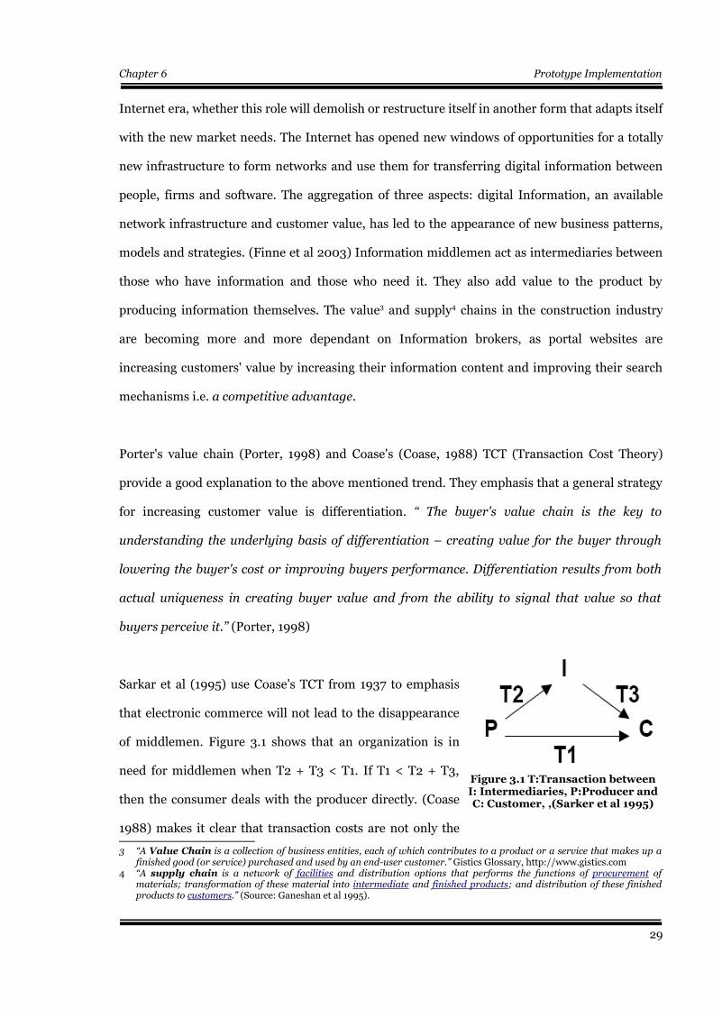
Sarkar et al (1995) use Coase's TCT from 1937 to emphasis
that electronic commerce will not lead to the disappearance
of middlemen. Figure 3.1 shows that an organization is in
need for middlemen when T2 + T3 < T1. If T1 < T2 + T3,
then the consumer deals with the producer directly. (Coase
1988) makes it clear that transaction costs are not only the
3 “A Value Chain is a collection of business entities, each of which contributes to a product or a service that makes up afinished good (or service) purchased and used by an end-user customer.” Gistics Glossary, http://www.gistics.com
4 “A supply chain is a network of facilities and distribution options that performs the functions of procurement ofmaterials; transformation of these material into intermediate and finished products; and distribution of these finishedproducts to customers.” (Source: Ganeshan et al 1995).
29
Figure 3.1 T:Transaction betweenI: Intermediaries, P:Producer andC: Customer, ,(Sarker et al 1995)
Chapter 6 Prototype Implementation
the direct cost or price, but also includes everything needed to carry out a market transaction.
This could include things such as search for information costs, bargaining and decision costs.
Researchers like (Finne 2003) argue that the ability of portal websites and construction product
middlemen to restructure information in formats that their customers' computer applications
can understand, would reduce transaction costs and act as a value added competitive advantage.
Furthermore, if the services provided by middlemen could include the provision of product
information covering the life-span of the construction product, this would lead to significant
economies of scale (ibid). This is specially true in cases where the middlemen or portal websites
are capable of giving customers value, that is greater than the customer's costs for producing the
same services themselves. In other words, if the overall costs would still be less than when not
using the service. (Porter 1998)
3.2.2 Branding
Branding is one of the marketing strategies used to promote a product. People are reluctant to
buy products that do not have a good reputation or did not stand the test of time. Researchers
like (Wimmer et al 2000, Smith 2001, Coltman et al 2001) emphasise that a brand name has a
significant role on the Internet. Branding is like a stamp of quality assurance. Branding also
means the differentiation of the product. Differentiation creates difficulty in comparing products,
and can facilitate premium pricing. (Coltman et al 2001, Öörni and Klein 2003 Smith and
Brynjolfsson 2001) The quality correlated to a brand name should be also correlated to the
amount, dispersion, and trustworthiness of information provided by the service or the product.
This is another area where information middlemen could achieve “delivery on the brand”.
(Willcocks and Plant, 2001)
It seems that the above points have not been widely implemented by current commercial and
academic research work. Thus, we could conclude that the above mentioned aspects are of
significant importance and should be taken into consideration when attempting to consider
30

Chapter 6 Prototype Implementation
marketing and management aspects that could pull academic work from drawers and push it into
practical implementation.
3.2.3 Manufacturers and Suppliers
Suppliers more often than not give brand names to products that are produced by multiple
manufacturers so long as these products conform to certain norms and standards. The brand
name acts as a symbol of quality, where customers correlate a certain level of quality to the brand
name. This association between customer's perception to a product and a certain brand name,
plays an important role in marketing strategies. Suppliers often order products to be
manufactured for themselves under a certain commercial brand name by a manufacturer. The
same manufacturer can be producing the same product under other brand names for other
suppliers. Hence, it is important to understand the manufacturer-supplier relation in such cases,
where information about construction products can be differentiated in to two types of
information, first is the technical information that is best known by the manufacturer and second
is the commercial information that is managed by the supplier. An example can be a cement
factory that produces cement under multiple names for multiple suppliers, each supplier can sell
its cement according to the perception of the customer to the quality of the brand name and the
services associated with it.
Thus, it might be one of the shortcomings of the previous research projects, that they did not try
to model the separation between manufacturers and suppliers in the supply chain and mostly
depended on a single focal point of information which is the supplier or the manufacturer as a
single entity, where, however, this segment is fragmented and the information transfer has to
depend on a distributed infrastructure that simulates reality rather than the assumption of an
ideal case of a single focal point of information. However, there exist also cases where the
manufacturer conducts his own marketing strategies and sells his products under his own brand
name and pricing strategies. In such cases, the manufacturer and the supplier can be treated as
one entity, in cases where the manufacturer plays the supplier's role.
31
Chapter 6 Prototype Implementation
3.2.4 Prefabrication versus on Site Production
One of the peculiarities of the construction industry is that a considerable portion of the
construction work is produced on site and not 100% of the products come to the construction site
on a back of a lorry. By considering this fact at various stages of the value chain, information that
belongs to the products that are fully or partially constructed on site has to be mirrored in the
building information model. If we focused on such on site activities, we will find that more often
than not they are produced by sub-contractors. At this point the manufacturer–supplier
information output in the value chain has to be adjusted to suit the nature of the construction
industry. One suggestion to solve this problem would be to consider the main contractor as the
supplier and the sub-contractor as the manufacturer. By looking at this suggestion, we find that it
is true to a great extent. The sub-contractor is the one who owns the technical information and
the main contractor supplies the product or the service in the same manner as the supplier does
for prefabricated products. Moreover, the main contractor is more concerned about delivery
times, mark-up and organizational business aspects rather than technicalities of the
subcontracted work.
3.3 Life Cycle Information and Updates
Most of the mentioned research work has claimed to offer life-cycle information of the
construction product. However, the real need is not only for life-cycle information, but for
information over the life-cycle of the product. In other words, if the life-cycle information is
offered at the design or decision making stage and then it disappears, this is not of a great value
to the building information model. There is a need to a permanent source of information about
the product that can be easily identified and accessed at all life-cycle stages by all involved AEC
disciplines, i.e. information over the life-cycle rather than life-cycle information at a single
point in time. This approach also controls the acquisition of data and its management. It is better
to acquire information about a certain product as it is needed rather than keeping all the needed
and unneeded information about each product from the time the decision is taken to include the
32
Chapter 6 Prototype Implementation
product in the project. Furthermore, there are types of dynamic information that need to be
monitored and continually updated, e.g. price, availability and so forth.
3.4 Search Mechanisms
The search mechanisms that were addressed in the mentioned research projects can be
differentiated into three types:
● Text based searches
● Classifications and Standards searches
● Parametric Searches
3.4.1 Text based searches
The text (Key-Word) based searches suit HTML and PDF files. The key word can be the name of
the product, its manufacturer, its brand name or any of its attributes. This type of search is the
most dominant one at the majority of suppliers' commercial web pages and portal websites at the
time of writing this work.
3.4.2 Searches based on Classifications and Standards
In the search according to classifications and standards, categories of products are displayed and
the user has to navigate through them and make a decision. However, the problem with this type
of search is its dependence on local classification systems and standards. The same problem was
also propagated to some research projects that tried to develop their own XML schemas
according to such local classification systems and standards. In the mean time, classification
systems and standards are considered as part of the parameters of the product. Hence, its
existence is important and allowing multiple classifications and standards to be considered as
attributes of a product is also of no less importance. Away from this discussion, it should be also
33
Chapter 6 Prototype Implementation
mentioned that there are researchers who adopt another view; that standards should be avoided,
even fought against, because they prevent differentiation and lock-in, and thus premium pricing.
(Sharpio and Varian 1999a, Sharpio and Varian, 1999b) At any rate, in the scope of this research
work multiple standards and classification systems should be considered as part of the product
attributes.
3.4.3 Parametric Searches
The parametric search is the most advanced one of the three types. However, it is not widely
implemented. One of the reasons for this problem could be attributed to the lack of standards
and norms that manage the taxonomy and identification of the parameters. Normally, the
parameters should be extracted from the building information model, then queries are carried
out according to these parameters and the chosen product's attributes are instantiated in the
model. Hence, it is a machine to machine language with the exception of the final decision-
making process for the selection and comparison between candidate construction products.
3.4.4 Retrieving Information using GUIDs
None of the research projects or commercial websites has mentioned the idea of referring to
construction product data through a Global Unique IDentifier. It would ultimately not be used as
a search mechanism, but it might help retrieving construction product data during the life-cycle
of the product. In other words, it might be able to act as the link that ties products in a building
information model with its life-cycle information. This might also help products referencing one
another, in cases where a composition or aggregation relationship between products exists.
Furthermore, it might help aggregating fragmented information that resides in distributed net
applications, e.g. technical information from a manufacturer and commercial (business)
information from a supplier and so forth.
34
Chapter 6 Prototype Implementation
3.5 A Building Information Model
The ideal case for a building information model is the case where one single data model is used
and all parties store and retrieve their data from it, from early design stages till use, maintenance
and demolition. (Björk 2003, Eastman 1999) However, this is not the case in reality. The
construction industry is fragmented, involves multidisciplinary professions and above all
includes a diversity of interests. Hence, this ideal imagination is far away from reality or any
practical application. Researchers like (Finne 2003) have the view that the real challenge is to
develop extensive and ubiquitous web based services that cover the whole range of players in the
CFM (Construction and Facilities Management) process. Moreover, the majority of industry
experts see the development towards non-proprietary value adding standardisation initiatives
like the IAI5/IFC6 as the major trend. (ITCON 2003, Koivu 2002) Other researchers like (Romo
2002a, Romo 2002b) claim that the existing building information models other than IFC are not
complete and that they may co-exist with IFC for sometime before vanishing. Researchers like
(Finne 2003) argue that IFC is getting increasingly important and that the use of IFC is just on
the brink of taking place. On the other hand (Koivu 2002) adopts a view that IFC might last ten to
twenty years before it is developed to a level that can enable full electronic commerce.
(Behrman, 2002) strongly criticizes the difficulty, slow speed of the development and complexity
of the implementation of the IFC model. In the meantime, Behrman's standardisation
development that is based on each use-case has not been more successful in the AEC industry or
replaced the IFC since the publication of the Behrman's report. On the contrary, the IAI has
published two versions of the IFC specification and has become the de-facto standard since 2002.
5 International Alliance for Interoperability, http://www.iai-na.org/about/mission.php6 Industy Foundation Classes, http://www.fiatech.org/projects/idim/ifcs.htm
35
Chapter 6 Prototype Implementation
3.6 Conclusion and Guidelines for the Research Work
3.6.1 Conclusion
This chapter has discussed some issues that are related to the problem of transfer of construction
product data between distributed network applications. Among these issues is the value and
supply chains.
The chapter came to a conclusion that information middlemen still play an important role in the
Internet era and their role will be reinforced with the increase of value added to the customer and
as long as Coase's Transaction Cost Theory is valid. The chapter followed this issue by a
discussion about the importance of branding in marketing strategies and how it leads often to
having the same product under multiple commercial brand names. However, differentiation of
the product could still be achieved through the services that are associated with it. This more
often that not results in the separation between business information related to the supplier and
the technical information related to the manufacturer. An important characteristic of the
construction industry is that buildings are still partially prefabricated and the rest of the
construction elements are constructed on site. This peculiarity in the value chain necessitates the
reflection of both types of product data on the building information model with emphasis on the
role of both contractors and subcontractors.
The chapter has also discussed the fact that building information models are in need for life-cycle
information all over the life cycle of the construction product and not only at the point of decision
making, i.e. information over the life cycle rather than life-cycle information at a single point in
time. Moreover it highlighted the importance of product information updates especially in the
business and commercial domains.
Various search mechanisms like the key word text based search, searches according to
classification systems and standards and parametric searches were discussed. The chapter
36

Chapter 6 Prototype Implementation
introduced the idea of a global unique identifier as a means of product data identification. It is
not a substitute to any of the search mechanisms, however, the author thinks it might help in
keeping product data linked to the building information model throughout its life cycle.
Finally, the issue of a building information model was discussed and it was concluded that the
IFC model with its non-proprietary characteristics is a considerable candidate for the prototype
implementation. Further reasons for this decision will be discussed in due course, while
proceeding in the chapters of this research work.
3.6.2 Guidelines
The author tried to extract some guidelines from the previous literature review and the analysis
that followed it. These Guidelines are:
● The need for the role of the Middleman or the portal website.
● The separation between the information that could be retrieved from the
supplier and the manufacturer in the supply chain.
● Considering various options of pre-fabrication and fabrication of construction
products on site.
● Considering the construction product hierarchy and its references to its
constituents and components.
● Availability of product life-cycle information over the life-cycle of the product
and allowing both information updates and extending the product's data.
● The ability to perform parametric searches and to allow for multiple
classification systems and standards.
37

Chapter 6 Prototype Implementation
● Identification of product data by using GUIDs.
● Using a non-proprietary Building Information Model
● Independence from commercial software applications and the support of
information exchange across heterogeneous platforms.
Chapter four will try to explain a design of a full specification for a model based on the above
mentioned guidelines. This model should be implemented in a comprehensive Software
prototype, that simulates all participants in the construction value chain.
It should be based on a distributed network system and not on a single database in order to avoid
information ownership and management problems.
Furthermore, chapter five will provide a proof of the solution concept developed in chapter four.
All parties involved in the construction value chain are simulated in a comprehensive network
application according to the above mentioned guidelines and the developed solution concept.
38
Chapter 6 Prototype Implementation
Chapter 4
Model of Proposed Solution
4.1 Introduction
Both the state of the art of BIMs (Building information Models) and electronic product
catalogues as well as the shortcomings of the previous research work were discussed in chapters
two and three. The author managed to reach a list of guidelines, that might be able to help
overcome the identified problems. A major guideline that has been emphasised throughout the
discussions in the previous chapters is the establishment of a link between objects in the building
information model (IFC model) and their continually updated life-cycle product data - technical
and commercial attributes- at the manufacturer and supplier respectively. This is hoped to enable
multidisciplinary cross industrial life-cycle information to be captured by IFC compatible
applications.
This chapter explains a new approach that is envisaged to help automating the development of a
building information model. The author suggests that the product information model should be
produced as a part of the construction product itself. This information model grows with the
development of the product e.g. the manufacturer would be responsible for the technical
properties and later the supplier or the wholesaler would be responsible for the dynamic
commercial aspects, when it is on sale at the physical market place or the virtual market space
(the Internet). The aggregation of this type of multidisciplinary and cross industrial information
is represented and made available on-line through the “OIPs” (Object Information Packs).
4.2 OIP Specifications
OIPs stand for Object Information Packs. An OIP is defined by the author as “A multidisciplinary
cross industrial continually updated pack of information about a construction product or a
39
Chapter 6 Prototype Implementation
service, upon which there is a need to retrieve predefined information at any point in the value
chain. This information pack acts as a base unit of information supply to BIMs (Building
Information Models) throughout the building's overall life cycle.”
In other words, an OIP is a construction oriented global life cycle identifier that links cross
industrial multidisciplinary information about a construction product or a service. It has been
designed to fit in an information exchange environment that suits the characteristics of the
various procurement systems in the construction industry's value chain .
4.2.1 Producer
The OIP has to represent both the technical and commercial information of a construction
product or service. The information is usually produced jointly between the manufacturer from
one side and the supplier, retailer, importer or wholesaler from the other side. This means that
the OIP is finally determined at the point of aggregation of both types of information i.e. technical
and commercial. This aggregation or double composition ensures the uniqueness of the OIP as an
identifier of the construction product or service and enables the retrieval of its dynamic
properties, i.e. commercial properties can be continually updated and the technical properties
can be extended. The complete OIP identifier is issued by the organization that owns the brand
name of the product regardless where, and by whom it has been manufactured.
On the other hand, in the case of construction products that are totally or partially manufactured
on site, the main contractor is considered to be the supplier, whereas the subcontractor
(specialist) would be considered as the manufacturer and consequently is responsible for the
technical information of the product. There are also cases where the manufacturer himself is the
brand name holder. In such cases, the manufacturer would be responsible for both kinds of
information.
40
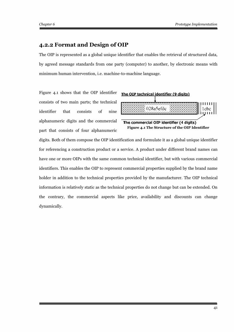
Chapter 6 Prototype Implementation
4.2.2 Format and Design of OIP
The OIP is represented as a global unique identifier that enables the retrieval of structured data,
by agreed message standards from one party (computer) to another, by electronic means with
minimum human intervention, i.e. machine-to-machine language.
Figure 4.1 shows that the OIP identifier
consists of two main parts; the technical
identifier that consists of nine
alphanumeric digits and the commercial
part that consists of four alphanumeric
digits. Both of them compose the OIP identification and formulate it as a global unique identifier
for referencing a construction product or a service. A product under different brand names can
have one or more OIPs with the same common technical identifier, but with various commercial
identifiers. This enables the OIP to represent commercial properties supplied by the brand name
holder in addition to the technical properties provided by the manufacturer. The OIP technical
information is relatively static as the technical properties do not change but can be extended. On
the contrary, the commercial aspects like price, availability and discounts can change
dynamically.
41
Figure 4.1 The Structure of the OIP Identifier
$
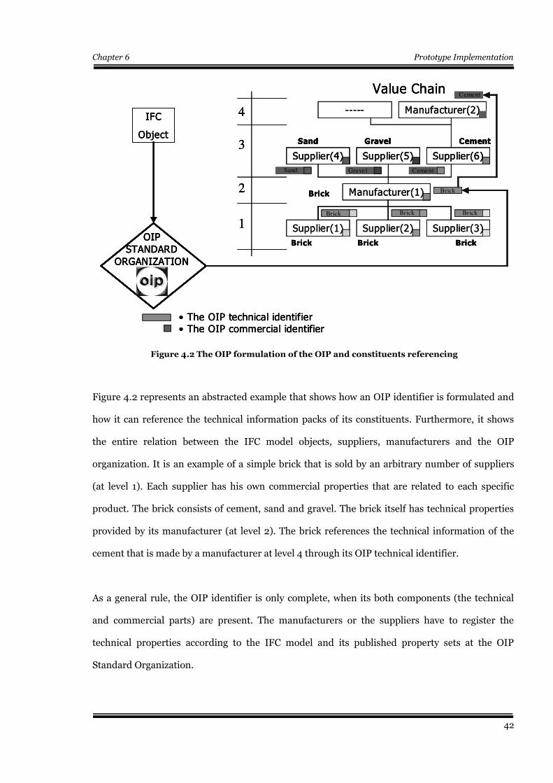
Chapter 6 Prototype Implementation
Figure 4.2 represents an abstracted example that shows how an OIP identifier is formulated and
how it can reference the technical information packs of its constituents. Furthermore, it shows
the entire relation between the IFC model objects, suppliers, manufacturers and the OIP
organization. It is an example of a simple brick that is sold by an arbitrary number of suppliers
(at level 1). Each supplier has his own commercial properties that are related to each specific
product. The brick consists of cement, sand and gravel. The brick itself has technical properties
provided by its manufacturer (at level 2). The brick references the technical information of the
cement that is made by a manufacturer at level 4 through its OIP technical identifier.
As a general rule, the OIP identifier is only complete, when its both components (the technical
and commercial parts) are present. The manufacturers or the suppliers have to register the
technical properties according to the IFC model and its published property sets at the OIP
Standard Organization.
42
Figure 4.2 The OIP formulation of the OIP and constituents referencing
IFC
Object
Value Chain
Manufacturer(2)-----
OIP
STANDARD
ORGANIZATION
Supplier(3)Supplier(2)Supplier(1)
Brick BrickBrick
Supplier(6)Supplier(5)Supplier(4)
CementGravelSand
Manufacturer(1)Brick
• The OIP technical identifier• The OIP commercial identifier
1
2
3
4
Brick Brick Brick
Sand Gravel Cement
Cement
Brick
IFC
Object
Value Chain
Manufacturer(2)-----
OIP
STANDARD
ORGANIZATION
Supplier(3)Supplier(2)Supplier(1)
Brick BrickBrick
Supplier(6)Supplier(5)Supplier(4)
CementGravelSand
Manufacturer(1)Brick
• The OIP technical identifier• The OIP commercial identifier
1
2
3
4IFC
Object
Value Chain
Manufacturer(2)-----
OIP
STANDARD
ORGANIZATION
OIP
STANDARD
ORGANIZATION
Supplier(3)Supplier(2)Supplier(1)
Brick BrickBrick
Supplier(6)Supplier(5)Supplier(4)
CementGravelSand
Supplier(6)Supplier(5)Supplier(4)
CementGravelSand
Manufacturer(1)Brick
• The OIP technical identifier• The OIP commercial identifier
1
2
3
4
Brick Brick Brick
Sand Gravel Cement
Cement
Brick
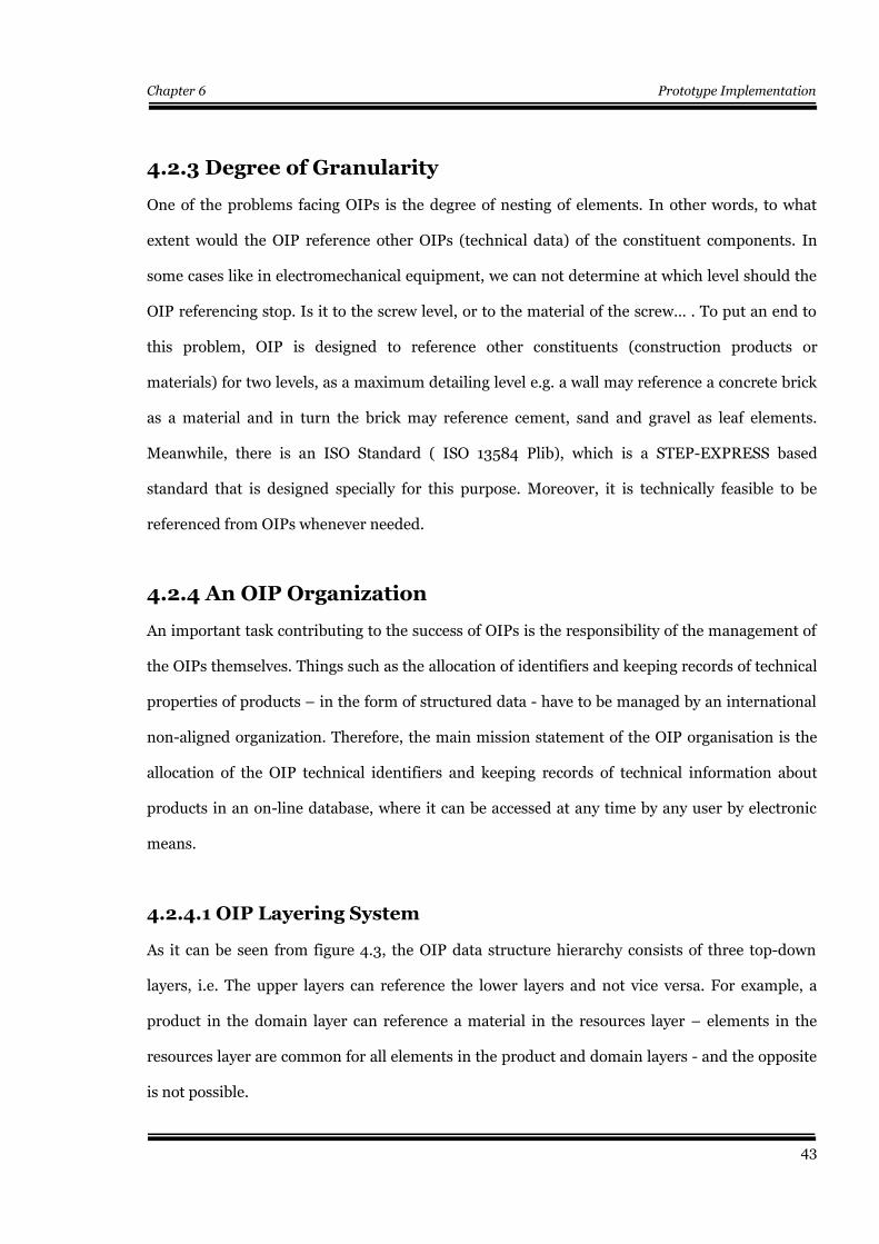
Chapter 6 Prototype Implementation
4.2.3 Degree of Granularity
One of the problems facing OIPs is the degree of nesting of elements. In other words, to what
extent would the OIP reference other OIPs (technical data) of the constituent components. In
some cases like in electromechanical equipment, we can not determine at which level should the
OIP referencing stop. Is it to the screw level, or to the material of the screw… . To put an end to
this problem, OIP is designed to reference other constituents (construction products or
materials) for two levels, as a maximum detailing level e.g. a wall may reference a concrete brick
as a material and in turn the brick may reference cement, sand and gravel as leaf elements.
Meanwhile, there is an ISO Standard ( ISO 13584 Plib), which is a STEP-EXPRESS based
standard that is designed specially for this purpose. Moreover, it is technically feasible to be
referenced from OIPs whenever needed.
4.2.4 An OIP Organization
An important task contributing to the success of OIPs is the responsibility of the management of
the OIPs themselves. Things such as the allocation of identifiers and keeping records of technical
properties of products – in the form of structured data - have to be managed by an international
non-aligned organization. Therefore, the main mission statement of the OIP organisation is the
allocation of the OIP technical identifiers and keeping records of technical information about
products in an on-line database, where it can be accessed at any time by any user by electronic
means.
4.2.4.1 OIP Layering System
As it can be seen from figure 4.3, the OIP data structure hierarchy consists of three top-down
layers, i.e. The upper layers can reference the lower layers and not vice versa. For example, a
product in the domain layer can reference a material in the resources layer – elements in the
resources layer are common for all elements in the product and domain layers - and the opposite
is not possible.
43
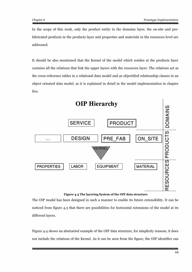
Chapter 6 Prototype Implementation
In the scope of this work, only the product entity in the domains layer, the on-site and pre-
fabricated products in the products layer and properties and materials in the resources level are
addressed.
It should be also mentioned that the Kernel of the model which resides at the products layer
contains all the relations that link the upper layers with the resources layer. The relations act as
the cross-reference tables in a relational data model and as objectified relationship classes in an
object oriented data model, as it is explained in detail in the model implementation in chapter
five.
The OIP model has been designed in such a manner to enable its future extensibility. It can be
noticed from figure 4.3 that there are possibilities for horizontal extensions of the model at its
different layers.
Figure 4.4 shows an abstracted example of the OIP data structure, for simplicity reasons, it does
not include the relations of the Kernel. As it can be seen from the figure, the OIP identifier can
44
Figure 4.3 The layering System of the OIP data structure
SERVICE
ON_SITEPRE_FAB
PRODUCT
DESIGN…
PROPERTIES
KERNEL
LABOR EQUIPMENT MATERIAL
OIP Hierarchy
DO
MA
INS
RE
SO
UR
CE
SP
RO
DU
CT
S
SERVICE
ON_SITEPRE_FAB
PRODUCT
DESIGN…
PROPERTIES
KERNEL
LABOR EQUIPMENT MATERIAL
OIP Hierarchy
DO
MA
INS
RE
SO
UR
CE
SP
RO
DU
CT
S
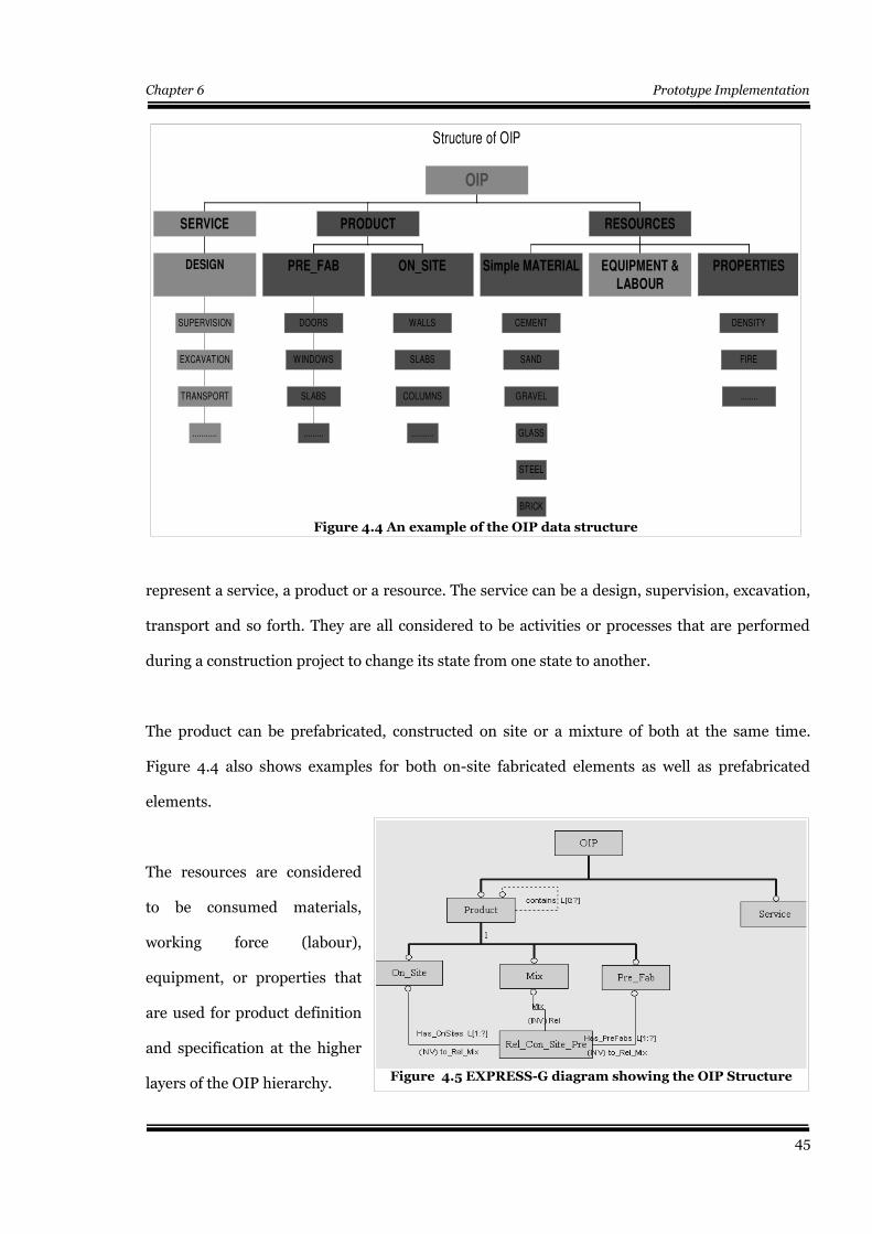
Chapter 6 Prototype Implementation
represent a service, a product or a resource. The service can be a design, supervision, excavation,
transport and so forth. They are all considered to be activities or processes that are performed
during a construction project to change its state from one state to another.
The product can be prefabricated, constructed on site or a mixture of both at the same time.
Figure 4.4 also shows examples for both on-site fabricated elements as well as prefabricated
elements.
The resources are considered
to be consumed materials,
working force (labour),
equipment, or properties that
are used for product definition
and specification at the higher
layers of the OIP hierarchy.
45
Figure 4.4 An example of the OIP data structure
Structure of OIP
...........
TRANSPORT
EXCAVATION
SUPERVISION
DESIGN
SERVICE
.........
SLABS
WINDOWS
DOORS
PRE_FAB
..........
COLUMNS
SLABS
WALLS
ON_SITE
PRODUCT
BRICK
STEEL
GLASS
GRAVEL
SAND
CEMENT
Simple MATERIAL EQUIPMENT &
LABOUR
........
FIRE
DENSITY
PROPERTIES
RESOURCES
OIP
Figure 4.5 EXPRESS-G diagram showing the OIP Structure
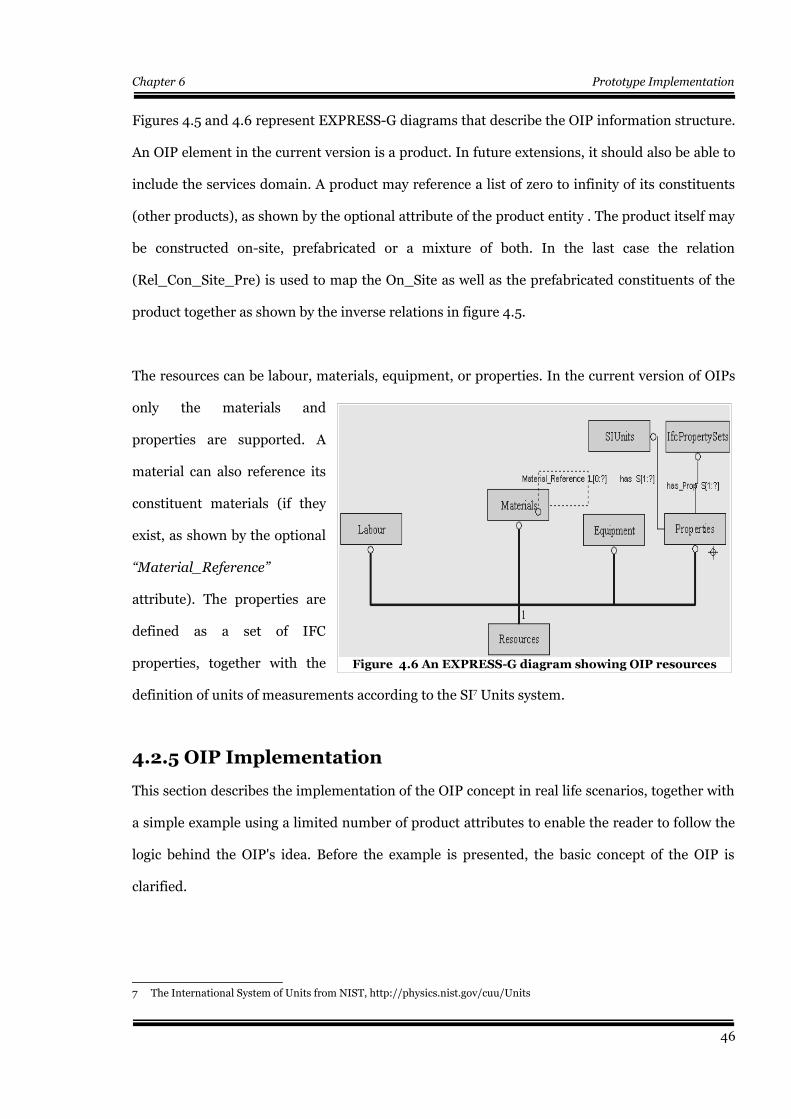
Chapter 6 Prototype Implementation
Figures 4.5 and 4.6 represent EXPRESS-G diagrams that describe the OIP information structure.
An OIP element in the current version is a product. In future extensions, it should also be able to
include the services domain. A product may reference a list of zero to infinity of its constituents
(other products), as shown by the optional attribute of the product entity . The product itself may
be constructed on-site, prefabricated or a mixture of both. In the last case the relation
(Rel_Con_Site_Pre) is used to map the On_Site as well as the prefabricated constituents of the
product together as shown by the inverse relations in figure 4.5.
The resources can be labour, materials, equipment, or properties. In the current version of OIPs
only the materials and
properties are supported. A
material can also reference its
constituent materials (if they
exist, as shown by the optional
“Material_Reference”
attribute). The properties are
defined as a set of IFC
properties, together with the
definition of units of measurements according to the SI7 Units system.
4.2.5 OIP Implementation
This section describes the implementation of the OIP concept in real life scenarios, together with
a simple example using a limited number of product attributes to enable the reader to follow the
logic behind the OIP's idea. Before the example is presented, the basic concept of the OIP is
clarified.
7 The International System of Units from NIST, http://physics.nist.gov/cuu/Units
46
Figure 4.6 An EXPRESS-G diagram showing OIP resources
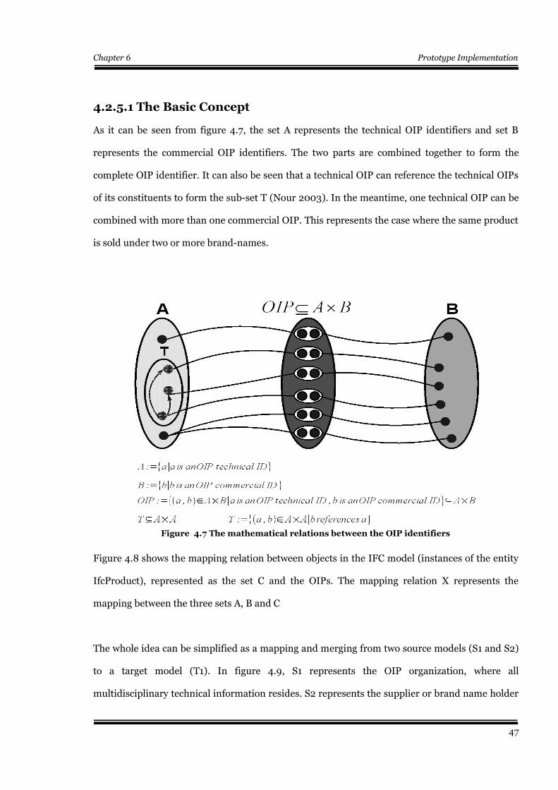
Chapter 6 Prototype Implementation
4.2.5.1 The Basic Concept
As it can be seen from figure 4.7, the set A represents the technical OIP identifiers and set B
represents the commercial OIP identifiers. The two parts are combined together to form the
complete OIP identifier. It can also be seen that a technical OIP can reference the technical OIPs
of its constituents to form the sub-set T (Nour 2003). In the meantime, one technical OIP can be
combined with more than one commercial OIP. This represents the case where the same product
is sold under two or more brand-names.
Figure 4.8 shows the mapping relation between objects in the IFC model (instances of the entity
IfcProduct), represented as the set C and the OIPs. The mapping relation X represents the
mapping between the three sets A, B and C
The whole idea can be simplified as a mapping and merging from two source models (S1 and S2)
to a target model (T1). In figure 4.9, S1 represents the OIP organization, where all
multidisciplinary technical information resides. S2 represents the supplier or brand name holder
47
Figure 4.7 The mathematical relations between the OIP identifiers
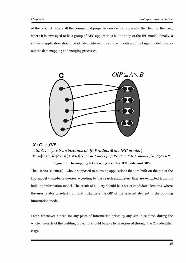
Chapter 6 Prototype Implementation
of the product; where all the commercial properties reside. T1 represents the client or the user,
where it is envisaged to be a group of AEC applications built on top of the IFC model. Finally, a
software application should be situated between the source models and the target model to carry
out the data mapping and merging processes.
The user(s) (client(s)) - who is supposed to be using applications that are built on the top of the
IFC model - conducts queries according to the search parameters that are extracted from his
building information model. The result of a query should be a set of candidate elements, where
the user is able to select from and instantiate the OIP of the selected element in the building
information model.
Later, whenever a need for any piece of information arises by any AEC discipline, during the
whole life-cycle of the building project, it should be able to be retrieved through the OIP identifier
(tag).
48
Figure 4.8 The mapping between objects in the IFC model and OIPs
X : c a , b C A B c is aninstance of IfcProduct IFC model , a , b OIP
X : C OIP
with C : c c is an instance of IfcProduct the IFC model
C OIP(AxB)OIP A B
X : c a , b C A B c is aninstance of IfcProduct IFC model , a , b OIP
X : C OIP
with C : c c is an instance of IfcProduct the IFC model
C OIP(AxB)C OIP(AxB)OIP A B
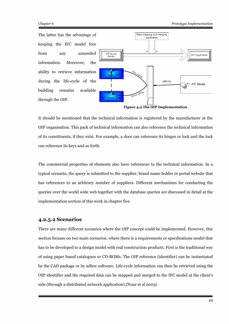
Chapter 6 Prototype Implementation
The latter has the advantage of
keeping the IFC model free
from any unneeded
information. Moreover, the
ability to retrieve information
during the life-cycle of the
building remains available
through the OIP.
It should be mentioned that the technical information is registered by the manufacturer at the
OIP organisation. This pack of technical information can also reference the technical information
of its constituents, if they exist. For example, a door can reference its hinges or lock and the lock
can reference its keys and so forth.
The commercial properties of elements also have references to the technical information. In a
typical scenario, the query is submitted to the supplier, brand name holder or portal website that
has references to an arbitrary number of suppliers. Different mechanisms for conducting the
queries over the world wide web together with the database queries are discussed in detail at the
implementation section of this work in chapter five.
4.2.5.2 Scenarios
There are many different scenarios where the OIP concept could be implemented. However, this
section focuses on two main scenarios, where there is a requirements or specifications model that
has to be developed to a design model with real construction products. First is the traditional way
of using paper based catalogues or CD-ROMs. The OIP reference (identifier) can be instantiated
by the CAD package or by adhoc software. Life-cycle information can then be retrieved using the
OIP identifier and the required data can be mapped and merged to the IFC model at the client’s
side (through a distributed network application).(Nour et al 2003)
49
Figure 4.9 The OIP Implementation
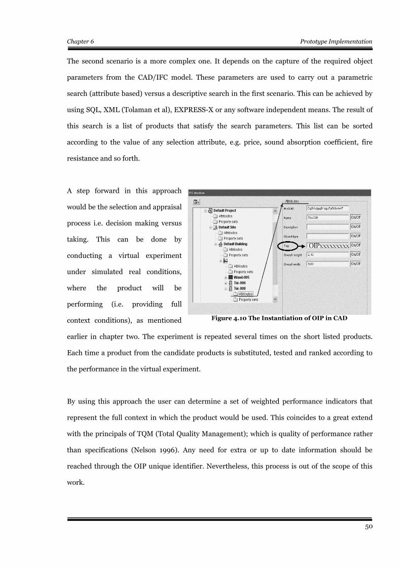
Chapter 6 Prototype Implementation
The second scenario is a more complex one. It depends on the capture of the required object
parameters from the CAD/IFC model. These parameters are used to carry out a parametric
search (attribute based) versus a descriptive search in the first scenario. This can be achieved by
using SQL, XML (Tolaman et al), EXPRESS-X or any software independent means. The result of
this search is a list of products that satisfy the search parameters. This list can be sorted
according to the value of any selection attribute, e.g. price, sound absorption coefficient, fire
resistance and so forth.
A step forward in this approach
would be the selection and appraisal
process i.e. decision making versus
taking. This can be done by
conducting a virtual experiment
under simulated real conditions,
where the product will be
performing (i.e. providing full
context conditions), as mentioned
earlier in chapter two. The experiment is repeated several times on the short listed products.
Each time a product from the candidate products is substituted, tested and ranked according to
the performance in the virtual experiment.
By using this approach the user can determine a set of weighted performance indicators that
represent the full context in which the product would be used. This coincides to a great extend
with the principals of TQM (Total Quality Management); which is quality of performance rather
than specifications (Nelson 1996). Any need for extra or up to date information should be
reached through the OIP unique identifier. Nevertheless, this process is out of the scope of this
work.
50
Figure 4.10 The Instantiation of OIP in CAD

Chapter 6 Prototype Implementation
4.2.5.3 Example
By looking at a simple example of a door
(IfcDoor), a door is selected according to
the first scenario from an electronic
catalogue from a portal web site (figure
4.12). It is transferred through a drag and
drop environment to the CAD application,
where the OIP is instantiated to the door’s
Tag in the IFC attributes (figure 4.10). The
door in the IFC model consists of two
main parts: the Lining and the panel as
shown in figure 4.11. The IFC published
property sets of the door include things
like the operation direction, overall size,
operation properties (swing), material, panel and lining detailed properties, door common
properties like: Infiltration, Thermal Transmittance, Fire, Security and Acoustic Ratings and so
forth. These properties might be needed in later design or facility management stages by different
AEC disciplines.
Access to this information should be enabled through the OIP. If at any time the need for more
information by any discipline arises, the product OIP can be accessed and the property can be
selected and merged to the IFC model at the client's side. If the product needs to be changed for
any reason, the same parameters could be used to conduct a new parametric search. This can also
be done as a result of a commercial property change e.g. price or availability updates. If the
product needs to be substituted with another product instance then a new OIP unique identifier
substitutes the old one and so forth.
51
Figure 4.11 IFC door Panel and Lining
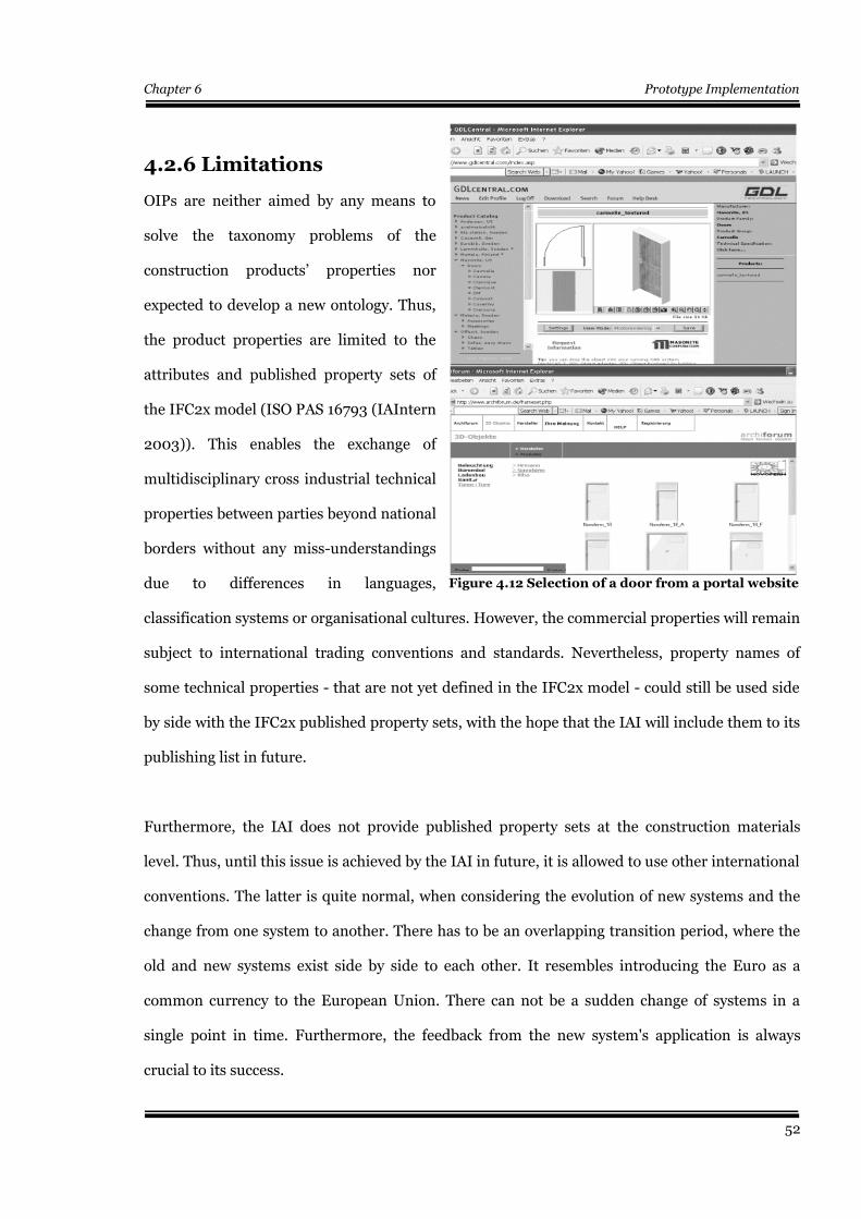
Chapter 6 Prototype Implementation
4.2.6 Limitations
OIPs are neither aimed by any means to
solve the taxonomy problems of the
construction products’ properties nor
expected to develop a new ontology. Thus,
the product properties are limited to the
attributes and published property sets of
the IFC2x model (ISO PAS 16793 (IAIntern
2003)). This enables the exchange of
multidisciplinary cross industrial technical
properties between parties beyond national
borders without any miss-understandings
due to differences in languages,
classification systems or organisational cultures. However, the commercial properties will remain
subject to international trading conventions and standards. Nevertheless, property names of
some technical properties - that are not yet defined in the IFC2x model - could still be used side
by side with the IFC2x published property sets, with the hope that the IAI will include them to its
publishing list in future.
Furthermore, the IAI does not provide published property sets at the construction materials
level. Thus, until this issue is achieved by the IAI in future, it is allowed to use other international
conventions. The latter is quite normal, when considering the evolution of new systems and the
change from one system to another. There has to be an overlapping transition period, where the
old and new systems exist side by side to each other. It resembles introducing the Euro as a
common currency to the European Union. There can not be a sudden change of systems in a
single point in time. Furthermore, the feedback from the new system's application is always
crucial to its success.
52
Figure 4.12 Selection of a door from a portal website
Chapter 6 Prototype Implementation
4.3 Conclusion
This chapter has introduced the OIP approach that might be able to help overcoming the
problems that were identified in the previous chapters. It could be concluded that the OIP is not
only an identifier that facilitates the retrieval of predefined information about construction
products or services according to the IFC2x model and its published property sets, but also an
information data structure that has a three layers top down hierarchy (domain, product and
resource layers). This hierarchy is reflected in the design of the database structure according to
the relations defined in the kernel of the system at the products layer. This structure is applied in
a runtime object oriented model and a persistent relational model (Microsoft Access Database) in
chapter five, where a mapping between the two models is provided.
The OIP concept depends on a distributed information network that emphasises the segregation
of technical and commercial product information in the value chain. In the meantime, both
information fragments are combined together at a certain point in the value chain to facilitate the
retrieval of any needed information by any discipline during the whole product's life-cycle.
The OIP approach alone is not enough to overcome the communication and interoperability
problems. The solution at the client side, which is represented by the development of software
tools that enable the mapping and merging of data about construction products according to the
IFC model is of paramount importance.
Moreover, the software tools at the client side go beyond the mapping and merging of product
data to the IFC model to performing a whole range of instantiation, deletion, update processes, in
addition to defining new query parameters in the model as well as extracting query parameters
that are defined by other software tools e.g. CAD, in addition to conducting parametric searches.
A simulation of a whole network distributes system is demonstrated in detail in chapter five (the
53

Chapter 6 Prototype Implementation
implementation). Moreover, Manufacturers and suppliers roles are also simulated to provide a
realistic proof of concept of this work.
54
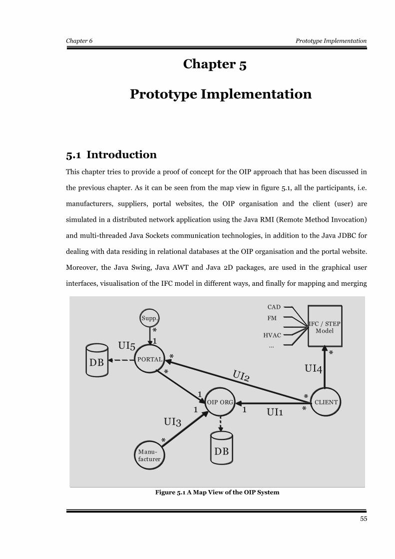
Chapter 6 Prototype Implementation
Chapter 5
Prototype Implementation
5.1 Introduction
This chapter tries to provide a proof of concept for the OIP approach that has been discussed in
the previous chapter. As it can be seen from the map view in figure 5.1, all the participants, i.e.
manufacturers, suppliers, portal websites, the OIP organisation and the client (user) are
simulated in a distributed network application using the Java RMI (Remote Method Invocation)
and multi-threaded Java Sockets communication technologies, in addition to the Java JDBC for
dealing with data residing in relational databases at the OIP organisation and the portal website.
Moreover, the Java Swing, Java AWT and Java 2D packages, are used in the graphical user
interfaces, visualisation of the IFC model in different ways, and finally for mapping and merging
55
Figure 5.1 A Map View of the OIP System
1
DB
DB
*
*
**
*
1
1
*
1
Supp.
Manu-facturer
OIP ORG. CLIENT
PORTAL
UI1
UI2
UI3
UI5
IFC / STEP Model
CAD
FM
HVAC
...1
*
UI4
DB
DB
*
*
**
*
1
1
*
1
Supp.
Manu-facturer
OIP ORG. CLIENT
PORTAL
UI1
UI2
UI3
UI5
IFC / STEP Model
CAD
FM
HVAC
...1
*
UI4
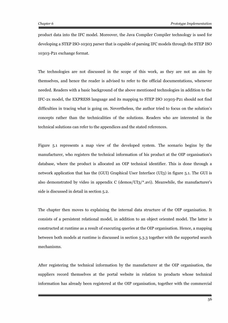
Chapter 6 Prototype Implementation
product data into the IFC model. Moreover, the Java Compiler Compiler technology is used for
developing a STEP ISO-10303 parser that is capable of parsing IFC models through the STEP ISO
10303-P21 exchange format.
The technologies are not discussed in the scope of this work, as they are not an aim by
themselves, and hence the reader is advised to refer to the official documentations, whenever
needed. Readers with a basic background of the above mentioned technologies in addition to the
IFC-2x model, the EXPRESS language and its mapping to STEP ISO 10303-P21 should not find
difficulties in tracing what is going on. Nevertheless, the author tried to focus on the solution's
concepts rather than the technicalities of the solutions. Readers who are interested in the
technical solutions can refer to the appendices and the stated references.
Figure 5.1 represents a map view of the developed system. The scenario begins by the
manufacturer, who registers the technical information of his product at the OIP organisation's
database, where the product is allocated an OIP technical identifier. This is done through a
network application that has the (GUI) Graphical User Interface (UI3) in figure 5.1. The GUI is
also demonstrated by video in appendix C (demos/UI3/*.avi). Meanwhile, the manufacturer's
side is discussed in detail in section 5.2.
The chapter then moves to explaining the internal data structure of the OIP organisation. It
consists of a persistent relational model, in addition to an object oriented model. The latter is
constructed at runtime as a result of executing queries at the OIP organisation. Hence, a mapping
between both models at runtime is discussed in section 5.3.3 together with the supported search
mechanisms.
After registering the technical information by the manufacturer at the OIP organisation, the
suppliers record themselves at the portal website in relation to products whose technical
information has already been registered at the OIP organisation, together with the commercial
56
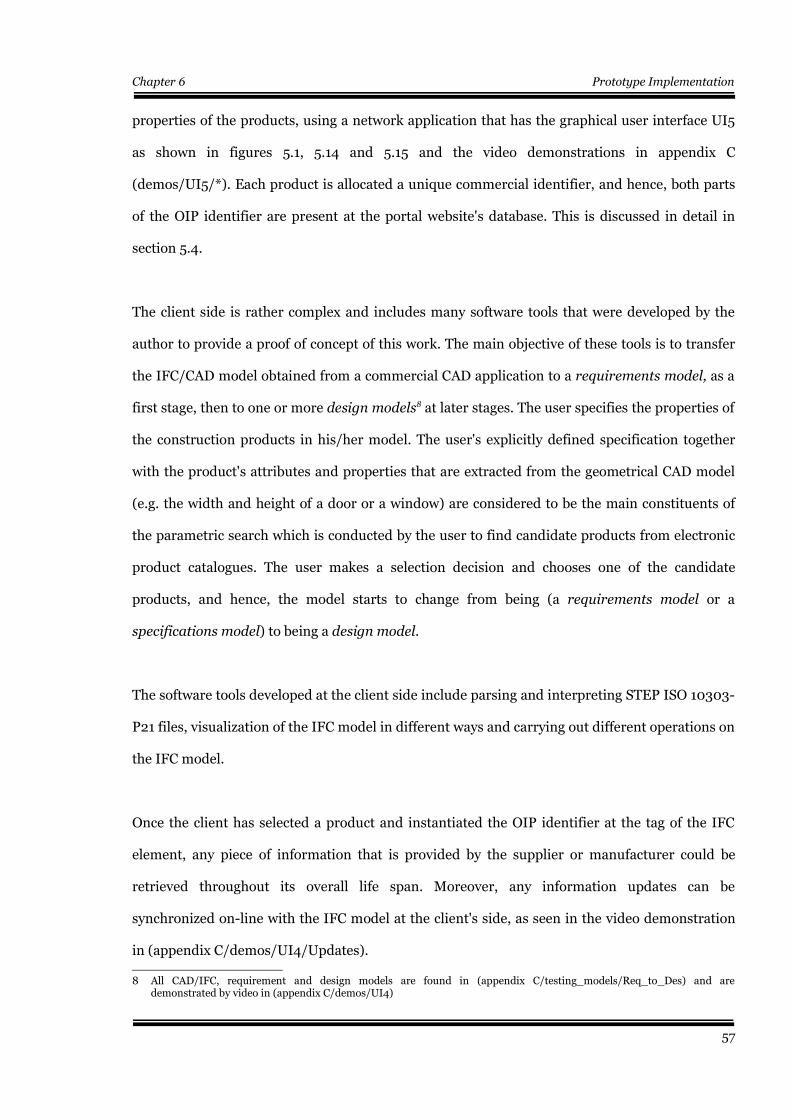
Chapter 6 Prototype Implementation
properties of the products, using a network application that has the graphical user interface UI5
as shown in figures 5.1, 5.14 and 5.15 and the video demonstrations in appendix C
(demos/UI5/*). Each product is allocated a unique commercial identifier, and hence, both parts
of the OIP identifier are present at the portal website's database. This is discussed in detail in
section 5.4.
The client side is rather complex and includes many software tools that were developed by the
author to provide a proof of concept of this work. The main objective of these tools is to transfer
the IFC/CAD model obtained from a commercial CAD application to a requirements model, as a
first stage, then to one or more design models8 at later stages. The user specifies the properties of
the construction products in his/her model. The user's explicitly defined specification together
with the product's attributes and properties that are extracted from the geometrical CAD model
(e.g. the width and height of a door or a window) are considered to be the main constituents of
the parametric search which is conducted by the user to find candidate products from electronic
product catalogues. The user makes a selection decision and chooses one of the candidate
products, and hence, the model starts to change from being (a requirements model or a
specifications model) to being a design model.
The software tools developed at the client side include parsing and interpreting STEP ISO 10303-
P21 files, visualization of the IFC model in different ways and carrying out different operations on
the IFC model.
Once the client has selected a product and instantiated the OIP identifier at the tag of the IFC
element, any piece of information that is provided by the supplier or manufacturer could be
retrieved throughout its overall life span. Moreover, any information updates can be
synchronized on-line with the IFC model at the client's side, as seen in the video demonstration
in (appendix C/demos/UI4/Updates).
8 All CAD/IFC, requirement and design models are found in (appendix C/testing_models/Req_to_Des) and aredemonstrated by video in (appendix C/demos/UI4)
57
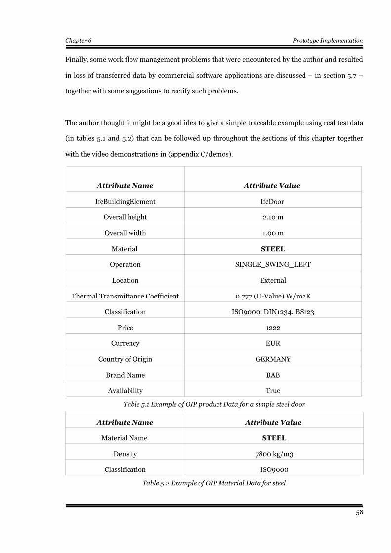
Chapter 6 Prototype Implementation
Finally, some work flow management problems that were encountered by the author and resulted
in loss of transferred data by commercial software applications are discussed – in section 5.7 –
together with some suggestions to rectify such problems.
The author thought it might be a good idea to give a simple traceable example using real test data
(in tables 5.1 and 5.2) that can be followed up throughout the sections of this chapter together
with the video demonstrations in (appendix C/demos).
Attribute Name Attribute Value
IfcBuildingElement IfcDoor
Overall height 2.10 m
Overall width 1.00 m
Material STEEL
Operation SINGLE_SWING_LEFT
Location External
Thermal Transmittance Coefficient 0.777 (U-Value) W/m2K
Classification ISO9000, DIN1234, BS123
Price 1222
Currency EUR
Country of Origin GERMANY
Brand Name BAB
Availability True
Table 5.1 Example of OIP product Data for a simple steel door
Attribute Name Attribute Value
Material Name STEEL
Density 7800 kg/m3
Classification ISO9000
Table 5.2 Example of OIP Material Data for steel
58
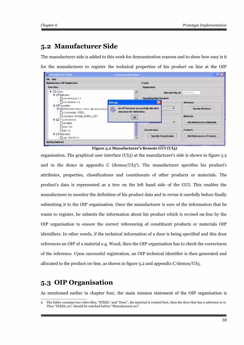
Chapter 6 Prototype Implementation
5.2 Manufacturer Side
The manufacturer side is added to this work for demonstration reasons and to show how easy is it
for the manufacturer to register the technical properties of his product on line at the OIP
organisation. The graphical user interface (UI3) at the manufacturer's side is shown in figure 5.2
and in the demo in appendix C (demos/UI39). The manufacturer specifies his product's
attributes, properties, classifications and constituents of other products or materials. The
product's data is represented as a tree on the left hand side of the GUI. This enables the
manufacturer to monitor the definition of his product data and to revise it carefully before finally
submitting it to the OIP organisation. Once the manufacturer is sure of the information that he
wants to register, he submits the information about his product which is revised on-line by the
OIP organisation to ensure the correct referencing of constituent products or materials OIP
identifiers. In other words, if the technical information of a door is being specified and this door
references an OIP of a material e.g. Wood, then the OIP organisation has to check the correctness
of the reference. Upon successful registration, an OIP technical identifier is then generated and
allocated to the product on-line, as shown in figure 5.2 and appendix C/demos/UI3.
5.3 OIP Organisation
As mentioned earlier in chapter four, the main mission statement of the OIP organisation is
9 The folder contains two video files; “STEEL” and “Door”, the material is created first, then the door that has a reference to it.Thus “STEEL.avi” should be watched before “Manufacturer.avi”.
59
Figure 5.2 Manufacturer's Remote GUI (UI3)

Chapter 6 Prototype Implementation
keeping records of construction products', materials' properties in a structured manner that
facilitates the capture of multidisciplinary cross industrial life-cycle information by IFC
compatible applications at the client side, in addition to the management and allocation of global
unique identifiers for the elements' technical information. In this stage the technical information
about a construction product should have been recorded in the OIP organization by the
manufacturer and allocated a global unique identifier for the Object Information Pack, as shown
in section 5.2. The coming section reveals the internal data structure of the product data residing
in the OIP organization. The data is persistently
saved in a relational database and converted at
run time as a result of SQL queries to the object
oriented model that is described in section 5.3.1.
This happens when the OIP organisation
receives a query from the client side or portal
websites. A query is executed in the relational
model and the OIP products (objects) that
satisfy the query conditions are built up
instantly at run time in the object oriented
model, where the properties of the products can
be navigated by the client on the remote
graphical user interface, as shown in figure 5.12
5.3.1 The OIP Object Oriented Model
The OIP object oriented model represents exactly the theory behind the OIP concept as discussed
earlier in chapter four. The diagrams in chapter four and the UML diagrams in this section show
together the structure of the run time OIP object oriented model. By looking at the UML diagram
in figure 5.3, we could notice that an OIP is a super type of either a service or a product. An OIP
product has a reference to an IFC element. The product itself can be a prefabricated, constructed
on-site or a mixture of both. The UML diagram also shows an example of an OIP_Door that
60
Figure 5.3 The UML diagram of the OIPconstruction products
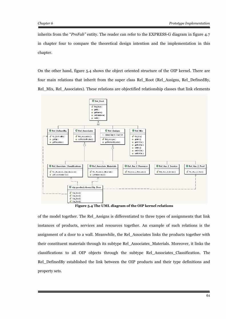
Chapter 6 Prototype Implementation
inherits from the “PreFab” entity. The reader can refer to the EXPRESS-G diagram in figure 4.7
in chapter four to compare the theoretical design intention and the implementation in this
chapter.
On the other hand, figure 5.4 shows the object oriented structure of the OIP kernel. There are
four main relations that inherit from the super class Rel_Root (Rel_Assigns, Rel_DefinedBy,
Rel_Mix, Rel_Associates). These relations are objectified relationship classes that link elements
of the model together. The Rel_Assigns is differentiated to three types of assignments that link
instances of products, services and resources together. An example of such relations is the
assignment of a door to a wall. Meanwhile, the Rel_Associates links the products together with
their constituent materials through its subtype Rel_Associates_Materials. Moreover, it links the
classifications to all OIP objects through the subtype Rel_Associates_Classification. The
Rel_DefinedBy established the link between the OIP products and their type definitions and
property sets.
61
Figure 5.4 The UML diagram of the OIP kernel relations
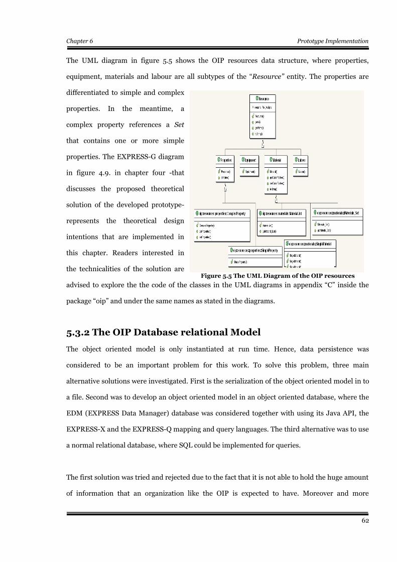
Chapter 6 Prototype Implementation
The UML diagram in figure 5.5 shows the OIP resources data structure, where properties,
equipment, materials and labour are all subtypes of the “Resource” entity. The properties are
differentiated to simple and complex
properties. In the meantime, a
complex property references a Set
that contains one or more simple
properties. The EXPRESS-G diagram
in figure 4.9. in chapter four -that
discusses the proposed theoretical
solution of the developed prototype-
represents the theoretical design
intentions that are implemented in
this chapter. Readers interested in
the technicalities of the solution are
advised to explore the the code of the classes in the UML diagrams in appendix “C” inside the
package “oip” and under the same names as stated in the diagrams.
5.3.2 The OIP Database relational Model
The object oriented model is only instantiated at run time. Hence, data persistence was
considered to be an important problem for this work. To solve this problem, three main
alternative solutions were investigated. First is the serialization of the object oriented model in to
a file. Second was to develop an object oriented model in an object oriented database, where the
EDM (EXPRESS Data Manager) database was considered together with using its Java API, the
EXPRESS-X and the EXPRESS-Q mapping and query languages. The third alternative was to use
a normal relational database, where SQL could be implemented for queries.
The first solution was tried and rejected due to the fact that it is not able to hold the huge amount
of information that an organization like the OIP is expected to have. Moreover and more
62
Figure 5.5 The UML Diagram of the OIP resources
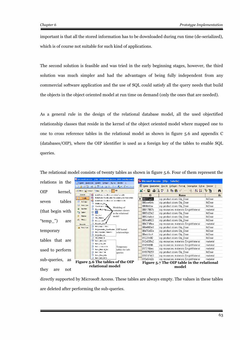
Chapter 6 Prototype Implementation
important is that all the stored information has to be downloaded during run time (de-serialized),
which is of course not suitable for such kind of applications.
The second solution is feasible and was tried in the early beginning stages, however, the third
solution was much simpler and had the advantages of being fully independent from any
commercial software application and the use of SQL could satisfy all the query needs that build
the objects in the object oriented model at run time on demand (only the ones that are needed).
As a general rule in the design of the relational database model, all the used objectified
relationship classes that reside in the kernel of the object oriented model where mapped one to
one to cross reference tables in the relational model as shown in figure 5.6 and appendix C
(databases/OIP), where the OIP identifier is used as a foreign key of the tables to enable SQL
queries.
The relational model consists of twenty tables as shown in figure 5.6. Four of them represent the
relations in the
OIP kernel,
seven tables
(that begin with
“temp_”) are
temporary
tables that are
used to perform
sub-queries, as
they are not
directly supported by Microsoft Access. These tables are always empty. The values in these tables
are deleted after performing the sub-queries.
63
Figure 5.7 The OIP table in the relationalmodel
Figure 5.6 The tables of the OIPrelational model
OIP kernel
relationships
Temporary tables for sub-
queries
Modeling of
container classes
in the relational
model
OIP kernel
relationships
Temporary tables for sub-
queries
Modeling of
container classes
in the relational
model

Chapter 6 Prototype Implementation
Figure 5.8 represents the relations between the entities (tables) in the relational model. The table
Oip contains the OIP technical unique identifier as its foreign key. It also contains the full name
of the Oip product including the package name as seen in figure 5.7. This helps in creating a new
instance of the product class in the object oriented model at run time (as needed). Finally, it
contains the name of the IFC entity that is represented by this OIP (e.g. IfcDoor, IfcWindow and
so forth).
Figure 5.8 also shows tables that represent examples of Oip products such as doors, windows and
materials. By taking Oip_Door as an example, it could be seen from figures 5.8 and 5.10 that the
Oip_Door table has references to the cross reference tables that represent the objectified
relationship classes in the kernel of the run time object oriented model. The elements in the table
Oip can be any construction product or material. It is also worth mentioning that a product can
have references to its materials and other constituent products through the cross reference tables
Rel_Associate_Materials and Rel_Assign_2_Prod respectively, in addition to classifications and
property sets, as shown in figure 5.8. The reader can refer to the tables of the above mentioned
entities in appendix C (databases/Oip).
64
Figure 5.8 OIP relational model
1
1
1
1
1
11 *1
1
1
11
11
1
1
1
1
1
11 *1
1
1
11
11
Container ClassesCross Reference Tables
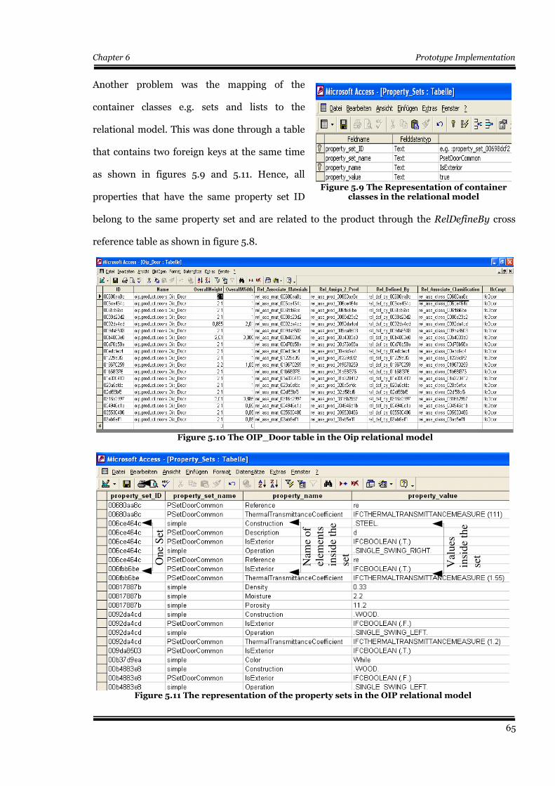
Chapter 6 Prototype Implementation
Another problem was the mapping of the
container classes e.g. sets and lists to the
relational model. This was done through a table
that contains two foreign keys at the same time
as shown in figures 5.9 and 5.11. Hence, all
properties that have the same property set ID
belong to the same property set and are related to the product through the RelDefineBy cross
reference table as shown in figure 5.8.
65
Figure 5.11 The representation of the property sets in the OIP relational model
On
e S
et
Nam
e o
f el
emen
ts
insi
de
the
set
Val
ues
in
sid
e th
e se
t
Figure 5.10 The OIP_Door table in the Oip relational model
Figure 5.9 The Representation of containerclasses in the relational model
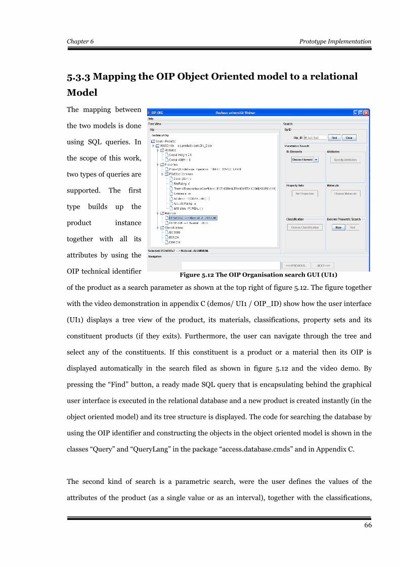
Chapter 6 Prototype Implementation
5.3.3 Mapping the OIP Object Oriented model to a relational
Model
The mapping between
the two models is done
using SQL queries. In
the scope of this work,
two types of queries are
supported. The first
type builds up the
product instance
together with all its
attributes by using the
OIP technical identifier
of the product as a search parameter as shown at the top right of figure 5.12. The figure together
with the video demonstration in appendix C (demos/ UI1 / OIP_ID) show how the user interface
(UI1) displays a tree view of the product, its materials, classifications, property sets and its
constituent products (if they exits). Furthermore, the user can navigate through the tree and
select any of the constituents. If this constituent is a product or a material then its OIP is
displayed automatically in the search filed as shown in figure 5.12 and the video demo. By
pressing the “Find” button, a ready made SQL query that is encapsulating behind the graphical
user interface is executed in the relational database and a new product is created instantly (in the
object oriented model) and its tree structure is displayed. The code for searching the database by
using the OIP identifier and constructing the objects in the object oriented model is shown in the
classes “Query” and “QueryLang” in the package “access.database.cmds” and in Appendix C.
The second kind of search is a parametric search, were the user defines the values of the
attributes of the product (as a single value or as an interval), together with the classifications,
66
Figure 5.12 The OIP Organisation search GUI (UI1)
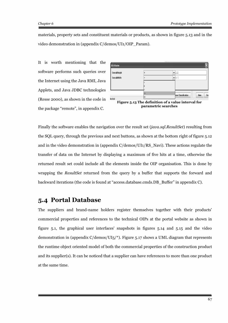
Chapter 6 Prototype Implementation
materials, property sets and constituent materials or products, as shown in figure 5.13 and in the
video demonstration in (appendix C/demos/UI1/OIP_Param).
It is worth mentioning that the
software performs such queries over
the Internet using the Java RMI, Java
Applets, and Java JDBC technologies
(Resse 2000), as shown in the code in
the package “remote”, in appendix C.
Finally the software enables the navigation over the result set (java.sql.ResultSet) resulting from
the SQL query, through the previous and next buttons, as shown at the bottom right of figure 5.12
and in the video demonstration in (appendix C/demos/UI1/RS_Navi). These actions regulate the
transfer of data on the Internet by displaying a maximum of five hits at a time, otherwise the
returned result set could include all the elements inside the OIP organisation. This is done by
wrapping the ResultSet returned from the query by a buffer that supports the forward and
backward iterations (the code is found at “access.database.cmds.DB_Buffer” in appendix C).
5.4 Portal Database
The suppliers and brand-name holders register themselves together with their products'
commercial properties and references to the technical OIPs at the portal website as shown in
figure 5.1, the graphical user interfaces' snapshots in figures 5.14 and 5.15 and the video
demonstration in (appendix C/demos/UI5/*). Figure 5.17 shows a UML diagram that represents
the runtime object oriented model of both the commercial properties of the construction product
and its supplier(s). It can be noticed that a supplier can have references to more than one product
at the same time.
67
Figure 5.13 The definition of a value interval forparametric searches
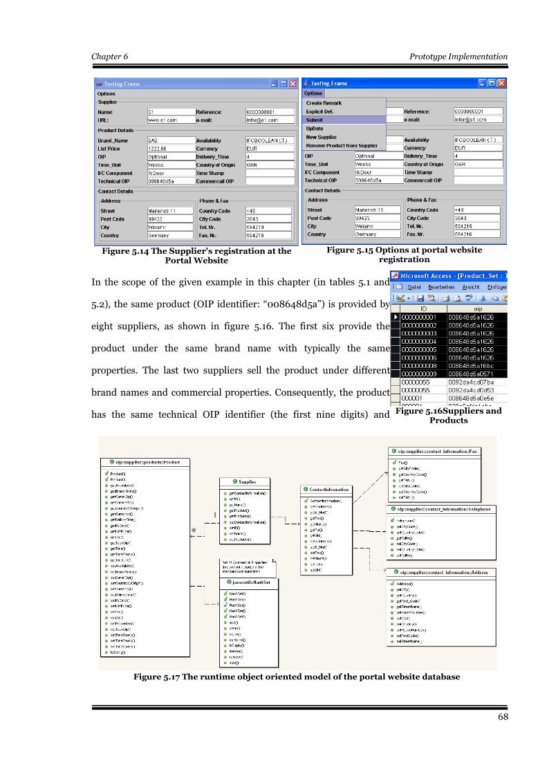
Chapter 6 Prototype Implementation
In the scope of the given example in this chapter (in tables 5.1 and
5.2), the same product (OIP identifier: “008648d5a”) is provided by
eight suppliers, as shown in figure 5.16. The first six provide the
product under the same brand name with typically the same
properties. The last two suppliers sell the product under different
brand names and commercial properties. Consequently, the product
has the same technical OIP identifier (the first nine digits) and
68
Figure 5.14 The Supplier's registration at thePortal Website
Figure 5.17 The runtime object oriented model of the portal website database
1
*
1
*
Figure 5.15 Options at portal websiteregistration
Figure 5.16Suppliers andProducts
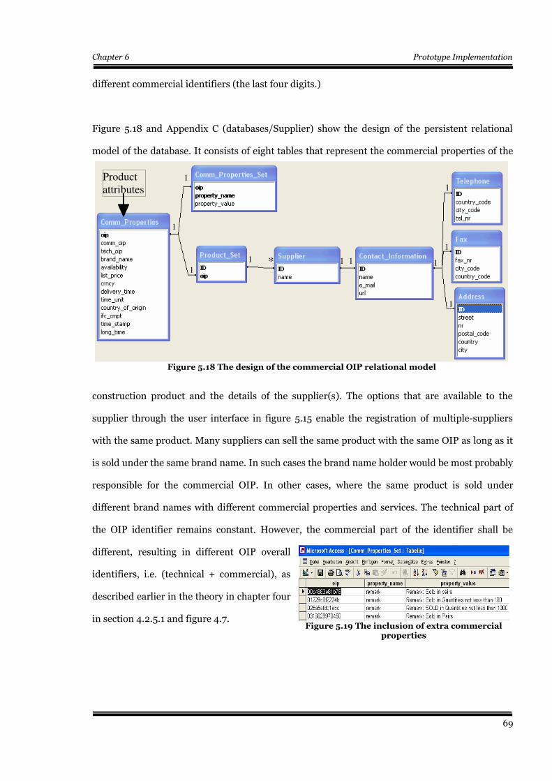
Chapter 6 Prototype Implementation
different commercial identifiers (the last four digits.)
Figure 5.18 and Appendix C (databases/Supplier) show the design of the persistent relational
model of the database. It consists of eight tables that represent the commercial properties of the
construction product and the details of the supplier(s). The options that are available to the
supplier through the user interface in figure 5.15 enable the registration of multiple-suppliers
with the same product. Many suppliers can sell the same product with the same OIP as long as it
is sold under the same brand name. In such cases the brand name holder would be most probably
responsible for the commercial OIP. In other cases, where the same product is sold under
different brand names with different commercial properties and services. The technical part of
the OIP identifier remains constant. However, the commercial part of the identifier shall be
different, resulting in different OIP overall
identifiers, i.e. (technical + commercial), as
described earlier in the theory in chapter four
in section 4.2.5.1 and figure 4.7.
69
Figure 5.19 The inclusion of extra commercialproperties
Figure 5.18 The design of the commercial OIP relational model
1
1
1
1 * 1 1 1
1
1
1
1
1
1
1 * 1 1 1
1
1
1
Product attributes
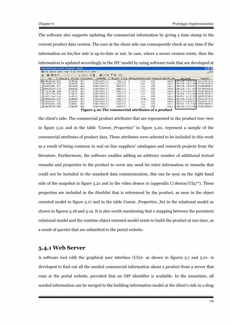
Chapter 6 Prototype Implementation
The software also supports updating the commercial information by giving a time stamp to the
current product data version. The user at the client side can consequently check at any time if the
information on his/her side is up-to-date or not. In case, where a newer version exists, then the
information is updated accordingly in the IFC model by using software tools that are developed at
the client's side. The commercial product attributes that are represented in the product tree view
in figure 5.21 and in the table “Comm_Properties” in figure 5.20, represent a sample of the
commercial attributes of product data. These attributes were selected to be included in this work
as a result of being common in real on line suppliers' catalogues and research projects from the
literature. Furthermore, the software enables adding an arbitrary number of additional textual
remarks and properties to the product to cover any need for extra information or remarks that
could not be included in the standard data communication, this can be seen on the right hand
side of the snapshot in figure 5.21 and in the video demos in (appendix C/demos/UI2/*). These
properties are included in the HashSet that is referenced by the product, as seen in the object
oriented model in figure 5.17 and in the table Comm_Properties_Set in the relational model as
shown in figures 5.18.and 5.19. It is also worth mentioning that a mapping between the persistent
relational model and the runtime object oriented model exists to build the product at run time, as
a result of queries that are submitted to the portal website.
5.4.1 Web Server
A software tool with the graphical user interface (UI2)- as shown in figures 5.1 and 5.21- is
developed to find out all the needed commercial information about a product from a server that
runs at the portal website, provided that an OIP identifier is available. In the meantime, all
needed information can be merged to the building information model at the client's side in a drag
70
Figure 5.20 The commercial attributes of a product
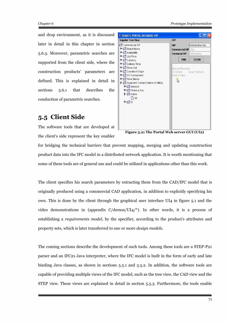
Chapter 6 Prototype Implementation
and drop environment, as it is discussed
later in detail in this chapter in section
5.6.3. Moreover, parametric searches are
supported from the client side, where the
construction products' parameters are
defined. This is explained in detail in
sections 5.6.1 that describes the
conduction of parametric searches.
5.5 Client Side
The software tools that are developed at
the client's side represent the key enabler
for bridging the technical barriers that prevent mapping, merging and updating construction
product data into the IFC model in a distributed network application. It is worth mentioning that
some of these tools are of general use and could be utilized in applications other than this work.
The client specifies his search parameters by extracting them from the CAD/IFC model that is
originally produced using a commercial CAD application, in addition to explicitly specifying his
own. This is done by the client through the graphical user interface UI4 in figure 5.1 and the
video demonstrations in (appendix C/demos/UI4/*). In other words, it is a process of
establishing a requirements model, by the specifier, according to the product's attributes and
property sets, which is later transferred to one or more design models.
The coming sections describe the development of such tools. Among these tools are a STEP-P21
parser and an IFC2x Java interpreter, where the IFC model is built in the form of early and late
binding Java classes, as shown in sections 5.5.1 and 5.5.2. In addition, the software tools are
capable of providing multiple views of the IFC model, such as the tree view, the CAD view and the
STEP view. These views are explained in detail in section 5.5.3. Furthermore, the tools enable
71
Figure 5.21 The Portal Web server GUI (UI2)
Remarks
Chapter 6 Prototype Implementation
operations that can be executed on the IFC model such as instantiation, updates or deletion of
information, bearing in mind the optimisation of the IFC model's size as discussed in section
5.5.4. Finally, the tools enable the client (user) to map and merge any needed product data on-
line to the IFC model by using a drag and drop environment. This is considered the process by
which the model is changed from being a requirements model to being a design model.
Moreover, checks for any updates to the commercial product data can be done at any point in
time, where the updated product information can by synchronized with the building information
model (IFC). This is described in detail in section 5.6.
Section 5.7 discusses work flow management aspects that were encountered by the author, after
exporting the IFC models that are instantiated with construction product data. The discussion
addresses the problem of data loss in addition to ways and means to rectify such problem.
5.5.1 Parsing STEP ISO 10303 – P21 Files
A major problem facing the implementation of IFC in university research projects is the process
of parsing STEP files and the instantiation of the IFC Model, which is defined in EXPRESS ISO-
10303-P11 language. In industry contexts, there are several generic EXPRESS based object
oriented databases that are capable of reading, updating, writing and mapping STEP models that
might be written against different EXPRESS schemata. However, the costs of such relatively new
technologies, at the time of writing this work, are extremely high, e.g EDM Express Data Manager
(EPM 2004). Furthermore, it enforces any software development to be dependent on a specific
commercial software tool that requires a considerable amount of time to get used to its
environment and to have a good grasp of its APIs. Moreover, in order to perform the above
mentioned operations and queries, mappings schemata have to be written in EXPRESS-X ISO
10303 P-14 by the user. In the meantime, it should be mentioned that the main aim behind
developing the parser is not to duplicate functionalities that are already made available by
commercial software applications. On the contrary, the parser and the interpreter are just
members of a group of tools that perform together functionalities that are not supported by a
72
Chapter 6 Prototype Implementation
single commercial software application at the time of writing this work. The developed tools are
integrated together to perform functionalities such as the visualisation of the IFC model in
different forms, extraction of search parameters from CAD/IFC models, the explicit definition of
property sets, conduction of parametric searches for products over the Internet, product data
retrieval, checking for updates of product data, the mapping and merging of product data on line
by the help of remote graphical user interfaces and so forth.
For many researchers, IFC is considered to be not more than a means for data exchange between
commercial software applications. It was found that one of the biggest barriers standing between
researchers and the IFC model is how to push the model itself from the theory in the IAI10
documentation to the practice of implementation. By exploring the Parser generation
technologies (Java Compiler Compiler), (Firmenich 2004), the idea of creating a STEP ISO-
10303-P21 parser (Nour 2004) was no longer an impossible task. It should be also mentioned
that the author is not a computer science specialist or a professional programmer. This shows
that the technology used for this purpose is user friendly and well documented. Nevertheless, a
good understanding of the EXPRESS language and the STEP standard are considered to be
essential prerequisites for developing such parsers.
This section tries to give a very brief introduction to the STEP, IFC, and EXPRESS (ISO 10303-11
EXPRESS 1994) technologies. However, it is not considered by any means to be a substitute for
the original documentation. The main focus is on the steps of creating a STEP parser and the
alternative options and decisions that could be made to suit different purposes behind the parser
and interpreter developments.
5.5.1.1 Analysis of a STEP file
STEP is considered to be the standard for exchange of product model data. It is the means by
which data defined by an EXPRESS schema can be transferred from one application to another.
10 IAI International Alliance for Interoperability, www.iai-international.org/iai_international/
73

Chapter 6 Prototype Implementation
STEP is a straightforward ASCII file format for exchanging
EXPRESS-defined data sets. The exchange file format is Part 21 of
the standard (ISO 10303 1994). Figure (5.22) shows that a STEP
file consists of two sections; first is the HEADER section and then
the DATA section. Both sections end with an 'ENDSEC;' statement
and are encapsulated between a starting 'ISO-10303-21;' statement
and an 'END-ISO-10303-21;' statement. The HEADER section of a
STEP part 21 file includes identifying information about the file
such as a textual description of the file, its name, the time stamp, the author(s) and organisation
name(s), the name of the EXPRESS schema and so forth. An example of a header is shown in
appendix A1.
The DATA section consists of an arbitrary number of IFC elements as shown in figure (5.23). The
figure also represents a real extract from an IFC (STEP) file - found in appendix A1 - that
represents an IfcWall and its IfcMaterial attributes. Entity instances are normally written using
an “internal mapping” from EXPRESS to STEP where the name of the entity type is followed by a
list of attributes in superclass-to-subclass order. It can be noticed that the attributes of the wall
can not be followed to reach the material. Both attributes #56 and #54 of the wall are references
to the placement and representation of the wall respectively. This is due to the fact that the
inverse attributes of the wall are not mapped to the STEP file11. Hence, the only means to match a
wall and its material attribute is through the IfcRelAssociatesMaterial (#58) that references both
the wall (#57 )and its material attribute (#37). It can also be seen that the attributes can be
classified as String, Numbers (Float, Double or Integer), references to other elements, null
references that are represented as [$] and finally container classes that are nested between extra
parenthesis.
11 The reader can refer to the EXPRESS definition of the entity IfcWallStandardCase to see the INVERSE relationship thatrefers to the associated material.(HasAssociations).
74
Figure 5.22 Constituents ofa STEP file, (Nour 2004)
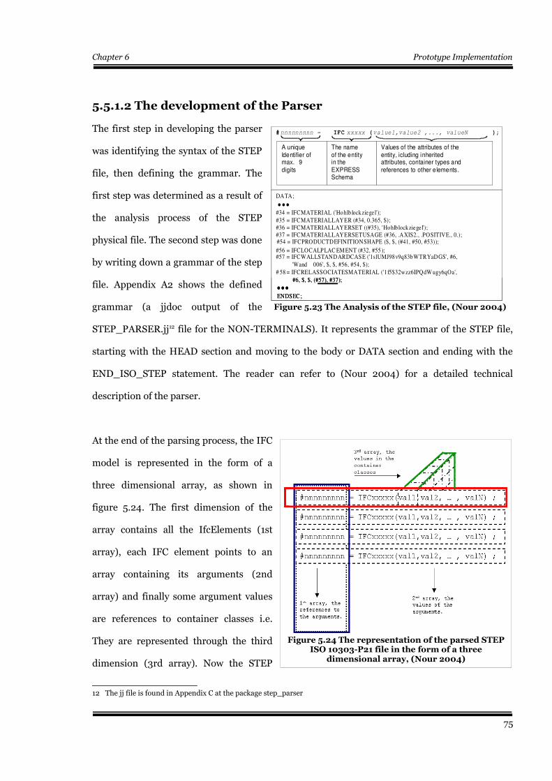
Chapter 6 Prototype Implementation
5.5.1.2 The development of the Parser
The first step in developing the parser
was identifying the syntax of the STEP
file, then defining the grammar. The
first step was determined as a result of
the analysis process of the STEP
physical file. The second step was done
by writing down a grammar of the step
file. Appendix A2 shows the defined
grammar (a jjdoc output of the
STEP_PARSER.jj12 file for the NON-TERMINALS). It represents the grammar of the STEP file,
starting with the HEAD section and moving to the body or DATA section and ending with the
END_ISO_STEP statement. The reader can refer to (Nour 2004) for a detailed technical
description of the parser.
At the end of the parsing process, the IFC
model is represented in the form of a
three dimensional array, as shown in
figure 5.24. The first dimension of the
array contains all the IfcElements (1st
array), each IFC element points to an
array containing its arguments (2nd
array) and finally some argument values
are references to container classes i.e.
They are represented through the third
dimension (3rd array). Now the STEP
12 The jj file is found in Appendix C at the package step_parser
75
Figure 5.24 The representation of the parsed STEPISO 10303-P21 file in the form of a three
dimensional array, (Nour 2004)
Figure 5.23 The Analysis of the STEP file, (Nour 2004)
# nnnnnnnnn = IFC xxxxx (value1,value2 ,..., valueN );
The name of the entity in the EXPRESS Schema
A uniqueIdentifier of max. 9 digits
Values of the attributes of the entity, icluding inherited attributes, container types and references to other elements.
DATA;
#34 = IFCMATERIAL ('Hohlb lockziegel');
#35 = IFCMATERIALLAYER (#34, 0.365, $);#36 = IFCMATERIALLAYERSET ((#35), 'Hohlblockziegel');#37 = IFCMATERIALLAYERSETUSAGE (#36, .AXIS2., .POSITIVE., 0.);
#57 = IFCWALLSTANDARDCASE ('1slUMJ98v9q83bWTRYaDGS', #6,
'Wand 006', $, $, #56, #54, $);
# 58 = IFCRELASSOCIATESMATERIAL ('1f5$32wzz6IPQdW ugy6qOa',
#6, $, $, (#57), #37);
ENDSEC ;
...
...
#56 = IFCLOCALP LAC EM ENT (#32, #55 );
#54 = IFCPRODUCTDEFINITIONSHAPE ($, $, (#41, #50, #53));
Chapter 6 Prototype Implementation
code should have already been parsed and is ready for interpretation by Java.
5.5.2 IFC Interpreter
The fact that STEP is a kind of mapping of objects defined in EXPRESS cannot be ignored. In
other words, each STEP file is written against an EXPRESS schema. This means that some
attributes -as earlier mentioned- can be absent in the STEP file (e.g. the derived and inverse
attributes). Moreover, Java is a programming and modeling language, whereas EXPRESS IS NOT
a programming language. There are lots of differences that can be pointed out between the two
languages. Among these differences are the support for multiple inheritance, different types of
container classes, logical, optional and Inverse attributes.
STEP physical files are tightly bound to the EXPRESS schemata they were written against.
Because the attribute values and their ordering are determined from the EXPRESS schema,
changes to the schema may cause problems with files written against the original version. This is
typically the case when trying to shift from using one version of the the IFC model to another. As
there is not enough space to discuss all of such aspects, in the context of this work, only
important issues that are encountered through the process of creating the interpreter are
discussed. The EXPRESS language is also discussed in detail in order to demonstrate how it is
mapped to Java in the software application.
5.5.2.1 EXPRESS
The history of EXPRESS begins in 1982 as the Product Data Definition Interface (PDDI) project
was established to specify an interface between design and manufacturing for product definitions
(Wilson 1987). During this project, Douglas Schenck at McDonnald Douglas developed a data
definition language called DSL (Schenck et al 1994). This language was the basis for EXPRESS.
The language went through many revision and feedback stages that influenced its design;
EXPRESS acquired design concepts from Ada, Algol, C, C++, Euler, Modula-2, Pascal, PL/I, and
SQL. The language developed an object oriented flavor, with objects, inheritance, and a rich
76
Chapter 6 Prototype Implementation
collection of types with the aim of describing information requirements and correctness
conditions necessary for meaningful data exchange. In December 1983, the International
Standards Organization (ISO) formed the TC184/SC4 committee that began working on the
Standard for Exchange of Product Model Data (STEP) with the aim of defining an integrated
product information model. This model defines specifications for the representation and
exchange of digital product information. Hence, a product data standard that incorporated
experience from national efforts such as IGES (IGES 1980), VDAF (VDAF 1986), SET (SET
1985), CAD (Kroszynski et al 1989) and PDDI (Birchfiel 1985), (PDDI 1984) was defined. For
further information about STEP APs ( Application Protocols ) and IRs (Integrated Resources) the
reader can consult the publications of the ISO TC184/SC4 committee.
EXPRESS is a data modelling language that allows unambiguous data definition and
specification of constraints on the defined data. It was published as ISO 10303 P-11 and used for
most product data standards such as: ISO 10303 (STEP), ISO 13584 (PLIB), ISO 15331
(MANDATE), ISO 15926 (OIL&GAS), IFC, EDIF and so forth. It is readable to humans and fully
computer interpretable. Although, EXPRESS is not a programming language, the ISO 10303
defines straight forward implementation forms.
It is worth also mentioning that there are EXPRESS 'dialects' within ISO 10303. These are the
EXPRESS ISO 10303 p11, which represents the textual notation, the EXPRESS-G that represents
the graphical notation, the EXPRESS-I (ISO 10303 -P12) that represents the instantiation
language, EXPRESS-X (ISO 10303-p14) that represents the mapping and viewing language. In
addition to some proprietary dialects such as EXPRESS-C, EXPRESS +, EXPRESS-V and
EXPRESS-M (EPM 2002, chap 2).
77
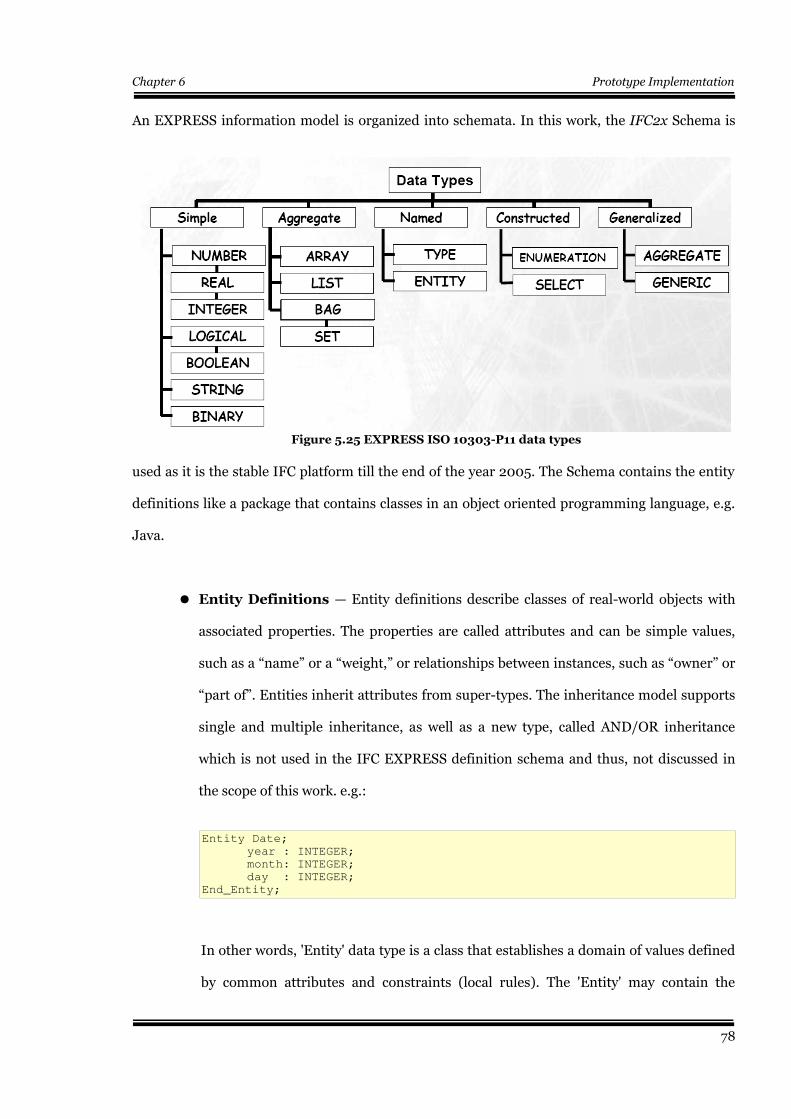
Chapter 6 Prototype Implementation
An EXPRESS information model is organized into schemata. In this work, the IFC2x Schema is
used as it is the stable IFC platform till the end of the year 2005. The Schema contains the entity
definitions like a package that contains classes in an object oriented programming language, e.g.
Java.
● Entity Definitions — Entity definitions describe classes of real-world objects with
associated properties. The properties are called attributes and can be simple values,
such as a “name” or a “weight,” or relationships between instances, such as “owner” or
“part of”. Entities inherit attributes from super-types. The inheritance model supports
single and multiple inheritance, as well as a new type, called AND/OR inheritance
which is not used in the IFC EXPRESS definition schema and thus, not discussed in
the scope of this work. e.g.:
Entity Date;
year : INTEGER;
month: INTEGER;
day : INTEGER;
End_Entity;
In other words, 'Entity' data type is a class that establishes a domain of values defined
by common attributes and constraints (local rules). The 'Entity' may contain the
78
Figure 5.25 EXPRESS ISO 10303-P11 data types

Chapter 6 Prototype Implementation
following declarations in the following sequence ( supertype declarations, subtype
decelerations, explicit attributes, derived attributes (DERIVED), inverse attributes
(INVERSE), uniqueness rules (UNIQUE), and local rules(WHERE)).
● Type Definitions — Type definitions describe ranges of possible values. The
language provides several built-in types, and the modeler can construct new types
using the built-in types, generalizations of several types, and aggregates of values. e.g.:
TYPE month = ENUMERATION OF(January,February,March,
April,May, June, July, August,September, October,
November,December);
END_TYPE;
ENTITY date;
Month_component : Month;
END_ENTITY;
The TYPE deceleration creates a new 'defined type' based on an 'underlying type'. It is
mainly used to increase the semantics of the underlying type through constraining the
type, usually by using local (WHERE) rules e.g. :
TYPE label = STRING; END_TYPE;
TYPE age= INTEGER;
WHERE SELF >= 0; -- “self” corresponds to “this” in Java
END_TYPE;
There are two main constrained types of the EXPRESS type. The first is the SELECT
data type. Its domain consists of the union of named data types in its select list. It is
used as a sort of generalization of dissimilar types. e.g.:
TYPE Circle_dim =SELECT (Radius, Diameter); END_TYPE;
TYPE Radius= SELECT (Inch, Meter); END_TYPE;
TYPE Diameter= SELECT (Inch, Meter); END_TYPE;
TYPE Inch =REAL; END_TYPE;
TYPE Meter = REAL; END_TYPE;
The second type is the ENUMERATION data type. It defines an ordered set of named
values (enumeration items) e.g.:
TYPE month =ENUMURATION OF (
January, February, March, April, May, June, July, August,
September, October, November, December);
END_TYPE;
ENTITY date;
Month_Component: Month;
79
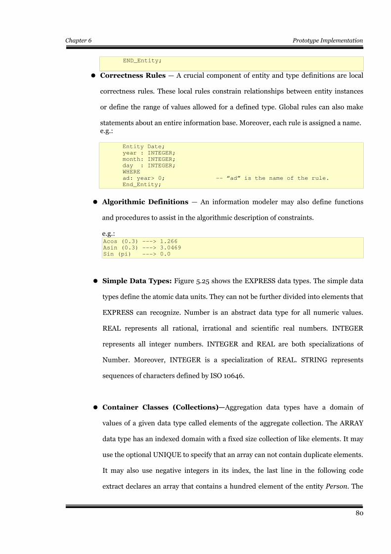
Chapter 6 Prototype Implementation
END_Entity;
● Correctness Rules — A crucial component of entity and type definitions are local
correctness rules. These local rules constrain relationships between entity instances
or define the range of values allowed for a defined type. Global rules can also make
statements about an entire information base. Moreover, each rule is assigned a name.e.g.:
Entity Date;
year : INTEGER;
month: INTEGER;
day : INTEGER;
WHERE
ad: year> 0; -- “ad” is the name of the rule.
End_Entity;
● Algorithmic Definitions — An information modeler may also define functions
and procedures to assist in the algorithmic description of constraints.
e.g.:Acos (0.3) ---> 1.266
Asin (0.3) ---> 3.0469
Sin (pi) ---> 0.0
● Simple Data Types: Figure 5.25 shows the EXPRESS data types. The simple data
types define the atomic data units. They can not be further divided into elements that
EXPRESS can recognize. Number is an abstract data type for all numeric values.
REAL represents all rational, irrational and scientific real numbers. INTEGER
represents all integer numbers. INTEGER and REAL are both specializations of
Number. Moreover, INTEGER is a specialization of REAL. STRING represents
sequences of characters defined by ISO 10646.
● Container Classes (Collections)—Aggregation data types have a domain of
values of a given data type called elements of the aggregate collection. The ARRAY
data type has an indexed domain with a fixed size collection of like elements. It may
use the optional UNIQUE to specify that an array can not contain duplicate elements.
It may also use negative integers in its index, the last line in the following code
extract declares an array that contains a hundred element of the entity Person. The
80
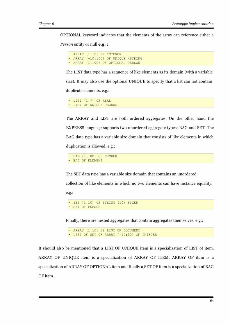
Chapter 6 Prototype Implementation
OPTIONAL keyword indicates that the elements of the array can reference either a
Person entity or null e.g. :
– ARRAY [1:10] OF INTEGER
– ARRAY [-10:100] OF UNIQUE (STRING)
– ARRAY [1:100] OF OPTIONAL PERSON
The LIST data type has a sequence of like elements as its domain (with a variable
size). It may also use the optional UNIQUE to specify that a list can not contain
duplicate elements. e.g.:
– LIST [1:?] OF REAL
– LIST OF UNIQUE PRODUCT
The ARRAY and LIST are both ordered aggregates. On the other hand the
EXPRESS language supports two unordered aggregate types; BAG and SET. The
BAG data type has a variable size domain that consists of like elements in which
duplication is allowed. e.g.:
– BAG [1:100] OF NUMBER
– BAG OF ELEMENT
The SET data type has a variable size domain that contains an unordered
collection of like elements in which no two elements can have instance equality.
e.g.:
– SET [1:10] OF STRING (10) FIXED
– SET OF PERSON
Finally, there are nested aggregates that contain aggregates themselves. e.g.:
– ARRAY [1:10] OF LIST OF DOCUMENT
– LIST OF SET OF ARRAY [-10:10] OF INTEGER
It should also be mentioned that a LIST OF UNIQUE item is a specialization of LIST of item.
ARRAY OF UNIQUE item is a specialization of ARRAY OF ITEM. ARRAY OF item is a
specialization of ARRAY OF OPTIONAL item and finally a SET OF item is a specialization of BAG
OF item.
81

Chapter 6 Prototype Implementation
In Java, on the other hand, the List class as well as the other container classes (e.g. Set) can
contain elements of any type as long as they are derived from the super class object. From the
above mentioned explanation; we can notice the differences between Java and EXPRESS in
imposing constraints on container classes.
5.5.2.2 STEP Standard Data Access Interface (SDAI)
A first step in mapping EXPRESS entities to Java classes is building an SDAI (Standard Data
Access Interface). The SDAI is a STEP API for EXPRESS defined data. The SDAI protocols
contain a description of the operations and functionalities that should be satisfied by the mapped
entities. The SDAI is described by several ISO standards documents. STEP Part 22 (ISO 10303-
P21 1995) contains a functional description of the SDAI operations, while Parts 23 (ISO 10303-
P23 1995) and 24 (ISO 10303 P-24 1995) describe how these operations are made available in the
C++ and C language environments. Bindings for CORBA/IDL and Java are also available. As a
general rule, all mapped EXPRESS entities should implement the SDAI interface. The only
purpose of this interface is the definition of rules that the generated Java classes must implement
to get access to their inner attributes (Loffredo, 2004). There are two main types of bindings
available:
●●●● SDAI Late Binding — In this approach, no pre-generated data structures are
used. Only one data structure is used for all of the definitions in an EXPRESS
model. The Inner attributes are usually collected in a container class, e.g. Vector or
List. Moreover, access to the objects is provided at runtime (ibid).
● SDAI Early Binding — An early binding approach makes the EXPRESS
information model available as specific programming language data structures for
each different definition in the EXPRESS model i.e. a dictionary (Schwarz 2004).
For example, an early binding such as the SDAI Java would contain specific Java
classes for each definition in the IFC2x Schema. One major advantage to this
82

Chapter 6 Prototype Implementation
approach is that the compiler can do extensive type checking on the application,
detecting conflicts at compile time. Special semantics or operations can also be
captured as operations tied to a particular data structure. Early bindings are
usually produced by an EXPRESS compiler. The compiler will parse, resolve, and
check the EXPRESS model, then passes control to a code generator to produce
data structures for that model. EXPRESS entity definitions are usually converted
to Java or C++ classes where type definitions are converted to either classes or
typedefs, and the EXPRESS inheritance structure is mapped into Java / C++
classes. Each class should have access and update methods for the stored
attributes, possibly access methods for simple, derived attributes, and constructors
to initialize new instances. It should be also noticed that Java does not support
multiple inheritance. At any rate, this problem is not encountered in this work due
to the fact the the EXPRESS definition of the IFC model does not use any direct
multiple inheritance.
● Other Approaches — The early and late bindings are not the only possible
approaches. In the scope of this work a mixed approach is implemented. This
approach provides the advantages of an early binding (compile-time type
checking) without the complexity introduced by modelling a huge number of
classes in the IFC model (there are more than three hundred and seventy leaf
classes, in addition to eighty nine defined types, twenty three select types and
one hundred and seventeen enumerations). It should be mentioned that in the the
early binding approach there is a restriction to predefined classes. This means
that if we need to interpret Ifc2x compliant STEP files, we have to model all the
elements of the IFC2x model to Java classes. In the meantime, if we need to
change to IFC2x2, then we have to do the same again with the whole model to
produce new Java binding classes. A mixed binding takes advantage of the
observation that applications rarely use all of the structures defined by the IFC2x
83
Chapter 6 Prototype Implementation
EXPRESS Schema. The subset of structures that are used, called the working
set, can be early-bound, while the rest of the Schema is late-bound (idem 2004).
Therefore, all data is still available, but the application development process is
simplified. The number of classes and files that are needed is reduced
dramatically, resulting in quicker compiles, simpler source control, and more
rapid development.
In the scope of this work the mixed approach was implemented, in the early
binding parts (for working classes) a more labour-intensive approach has been
used to hand-generate an early binding for the IFC2x model. Such a binding is not
100% compliant to the IFC EXPRESS model, due to the fact that EXPRESS data
types can not be mapped 1:1 to Java data types. In addition to the strong
constraints and rules that are imposed by the EXPRESS language.
Although this approach might provide a simplified programming interface, there
are some drawbacks to be aware of. Aside from the increased labour involved in
defining and implementing the binding, this method requires that the user should
understand the EXPRESS schema API completely, and be able to predict how it
will be used (Loffredo 2004).
5.5.2.3 Mapping EXPRESS Data Types
This section describes how EXPRESS language data types are mapped to the Java language
through the exchange structure (STEP physical file). The EXPRESS language includes TYPE and
ENTITY declarations, CONSTANT declarations, constraint specifications and algorithm
descriptions. Only EXPRESS primitive data types, TYPE, ENTITY and aggregations declarations,
are mapped to the exchange structure. Other elements of the language are not mapped to the
exchange structure and consequently are not mapped to Java classes. Table 5.3 shows the
84
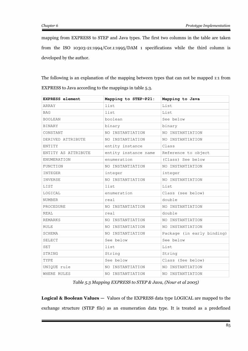
Chapter 6 Prototype Implementation
mapping from EXPRESS to STEP and Java types. The first two columns in the table are taken
from the ISO 10303-21:1994/Cor.1:1995/DAM 1 specifications while the third column is
developed by the author.
The following is an explanation of the mapping between types that can not be mapped 1:1 from
EXPRESS to Java according to the mappings in table 5.3.
EXPRESS element Mapping to STEP-P21: Mapping to Java
ARRAY list List
BAG list List
BOOLEAN boolean See below
BINARY binary binary
CONSTANT NO INSTANTIATION NO INSTANTIATION
DERIVED ATTRIBUTE NO INSTANTIATION NO INSTANTIATION
ENTITY entity instance Class
ENTITY AS ATTRIBUTE entity instance name Reference to object
ENUMERATION enumeration (Class) See below
FUNCTION NO INSTANTIATION NO INSTANTIATION
INTEGER integer integer
INVERSE NO INSTANTIATION NO INSTANTIATION
LIST list List
LOGICAL enumeration Class (see below)
NUMBER real double
PROCEDURE NO INSTANTIATION NO INSTANTIATION
REAL real double
REMARKS NO INSTANTIATION NO INSTANTIATION
RULE NO INSTANTIATION NO INSTANTIATION
SCHEMA NO INSTANTIATION Package (in early binding)
SELECT See below See below
SET list List
STRING String String
TYPE See below Class (See below)
UNIQUE rule NO INSTANTIATION NO INSTANTIATION
WHERE RULES NO INSTANTIATION NO INSTANTIATION
Table 5.3 Mapping EXPRESS to STEP & Java, (Nour et al 2005)
Logical & Boolean Values — Values of the EXPRESS data type LOGICAL are mapped to the
exchange structure (STEP file) as an enumeration data type. It is treated as a predefined
85
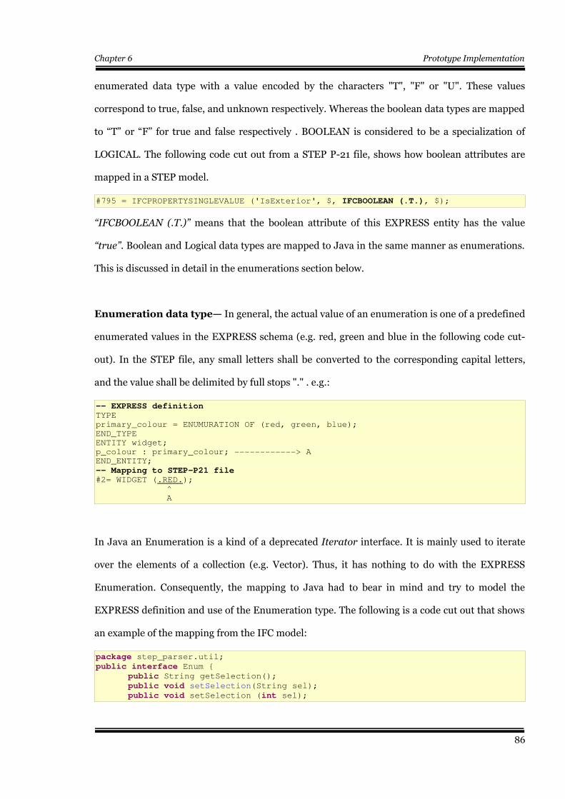
Chapter 6 Prototype Implementation
enumerated data type with a value encoded by the characters "T", "F" or "U". These values
correspond to true, false, and unknown respectively. Whereas the boolean data types are mapped
to “T” or “F” for true and false respectively . BOOLEAN is considered to be a specialization of
LOGICAL. The following code cut out from a STEP P-21 file, shows how boolean attributes are
mapped in a STEP model.
#795 = IFCPROPERTYSINGLEVALUE ('IsExterior', $, IFCBOOLEAN (.T.), $);
“IFCBOOLEAN (.T.)” means that the boolean attribute of this EXPRESS entity has the value
“true”. Boolean and Logical data types are mapped to Java in the same manner as enumerations.
This is discussed in detail in the enumerations section below.
Enumeration data type— In general, the actual value of an enumeration is one of a predefined
enumerated values in the EXPRESS schema (e.g. red, green and blue in the following code cut-
out). In the STEP file, any small letters shall be converted to the corresponding capital letters,
and the value shall be delimited by full stops "." . e.g.:
-- EXPRESS definition TYPE
primary_colour = ENUMURATION OF (red, green, blue);
END_TYPE
ENTITY widget;
p_colour : primary_colour; ------------> A
END_ENTITY;
-- Mapping to STEP-P21 file#2= WIDGET (.RED.);
^
A
In Java an Enumeration is a kind of a deprecated Iterator interface. It is mainly used to iterate
over the elements of a collection (e.g. Vector). Thus, it has nothing to do with the EXPRESS
Enumeration. Consequently, the mapping to Java had to bear in mind and try to model the
EXPRESS definition and use of the Enumeration type. The following is a code cut out that shows
an example of the mapping from the IFC model:
package step_parser.util;
public interface Enum {
public String getSelection();
public void setSelection(String sel);
public void setSelection (int sel);
86
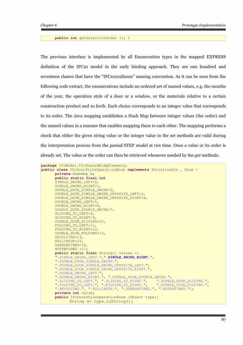
Chapter 6 Prototype Implementation
public int getSelectionOrder (); }
The previous interface is implemented by all Enumeration types in the mapped EXPRESS
definition of the IFC2x model in the early binding approach. They are one hundred and
seventeen classes that have the “IFCxxxxxEnum” naming convention. As it can be seen from the
following code extract, the enumerations include an ordered set of named values, e.g. the months
of the year, the operation style of a door or a window, or the materials relative to a certain
construction product and so forth. Each choice corresponds to an integer value that corresponds
to its order. The Java mapping establishes a Hash Map between integer values (the order) and
the named values in a manner that enables mapping them to each other. The mapping performs a
check that either the given string value or the integer value in the set methods are valid during
the interpretation process from the parsed STEP model at run time. Once a value or its order is
already set. The value or the order can then be retrieved whenever needed by the get methods.
package IfcModel.IfcSharedBldgElements;
public class IfcDoorStyleOperationEnum implements Serializable , Enum {
private HashMap m;
public static final int SINGLE_SWING_LEFT=0,
SINGLE_SWING_RIGHT=1,
DOUBLE_DOOR_SINGLE_SWING=2,
DOUBLE_DOOR_SINGLE_SWING_OPPOSITE_LEFT=3,
DOUBLE_DOOR_SINGLE_SWING_OPPOSITE_RIGHT=4,
DOUBLE_SWING_LEFT=5,
DOUBLE_SWING_RIGHT=6,
DOUBLE_DOOR_DOUBLE_SWING=7,
SLIDING_TO_LEFT=8,
SLIDING_TO_RIGHT=9,
DOUBLE_DOOR_SLIDING=10,
FOLDING_TO_LEFT=11,
FOLDING_TO_RIGHT=12,
DOUBLE_DOOR_FOLDING=13,
REVOLVING=14,
ROLLINGUP=15,
USERDEFINED=16,
NOTDEFINED =17;
public static final String[] values ={
".SINGLE_SWING_LEFT.",".SINGLE_SWING_RIGHT.",".DOUBLE_DOOR_SINGLE_SWING.",
".DOUBLE_DOOR_SINGLE_SWING_OPPOSITE_LEFT.",
".DOUBLE_DOOR_SINGLE_SWING_OPPOSITE_RIGHT.",
".DOUBLE_SWING_LEFT.",
".DOUBLE_SWING_RIGHT.", ".DOUBLE_DOOR_DOUBLE_SWING.",
".SLIDING_TO_LEFT.", ".SLIDING_TO_RIGHT.", ".DOUBLE_DOOR_SLIDING.",
".FOLDING_TO_LEFT.", ".FOLDING_TO_RIGHT.", ".DOUBLE_DOOR_FOLDING.",
".REVOLVING.", ".ROLLINGUP.", ".USERDEFINED.", ".NOTDEFINED."};
private int value;
public IfcDoorStyleOperationEnum (Object type){
String a= type.toString();
87
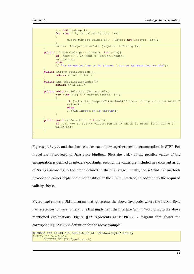
Chapter 6 Prototype Implementation
m = new HashMap();
for (int i=0; i< values.length; i++){
m.put((Object)values[i], ((Object)new Integer (i)));}
value= Integer.parseInt( (m.get(a).toString()));
}
public IfcDoorStyleOperationEnum (int enum){
if (enum >= 0 && enum <= values.length)value=enum;
else//("An Exception has to be thrown / out of Enumeration Bounds");
}
public String getSelection(){
return values[value];}
public int getSelectionOrder(){
return this.value}
public void setSelection(String sel){
for (int i=0; i < values.length; i++){
if (values[i].compareTo(sel)==0)// check if the value is valid ?value=i;
else//("An Exception is thrown");
}
}
public void setSelection (int sel){
if (sel >=0 && sel <= values.length)// check if order is in range ?value=sel;
}
}
Figures 5.26 , 5.27 and the above code extracts show together how the enumerations in STEP-P21
model are interpreted to Java early bindings. First the order of the possible values of the
enumeration is defined as integers constants. Second, the values are included in a constant array
of Strings according to the order defined in the first stage. Finally, the set and get methods
provide the earlier explained functionalities of the Enum interface, in addition to the required
validity checks.
Figure 5.26 shows a UML diagram that represents the above Java code, where the IfcDoorStyle
has references to two enumerations that implement the interface “Enum” according to the above
mentioned explanations. Figure 5.27 represents an EXPRESS-G diagram that shows the
corresponding EXPRESS definition for the above example.
EXPRESS ISO 10303-P11 definition of “IfcDoorStyle” entityENTITY IfcDoorStyle
SUBTYPE OF (IfcTypeProduct);
88
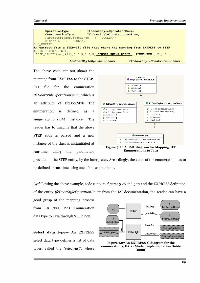
Chapter 6 Prototype Implementation
OperationType : IfcDoorStyleOperationEnum;
ConstructionType : IfcDoorStyleConstructionEnum;ParameterTakesPrecedence : BOOLEAN;
Sizeable : BOOLEAN;
END_ENTITY;
An extract from a STEP-P21 file that shows the mapping from EXPRESS to STEP#9015 = IFCDOORSTYLE
('OIP_01d2754ae',#195,$,$,$,$,$,$,.SINGLE_SWING_RIGHT.,.ALUMINIUM.,.F.,.F.);
^ ^
IfcDoorStyleOperationEnum IfcDoorStyleConstructionEnum
The above code cut out shows the
mapping from EXPRESS to the STEP-
P21 file for the enumeration
IfcDoorStyleOperationEnum, which is
an attribute of IfcDoorStyle The
enumeration is defined as a
single_swing_right instance. The
reader has to imagine that the above
STEP code is parsed and a new
instance of the class is instantiated at
run-time using the parameters
provided in the STEP entity, by the interpreter. Accordingly, the value of the enumeration has to
be defined at run-time using one of the set methods.
By following the above example, code cut outs, figures 5.26 and 5.27 and the EXPRESS definition
of the entity IfcDoorStyleOperationEnum from the IAI documentation, the reader can have a
good grasp of the mapping process
from EXPRESS P-11 Enumeration
data type to Java through STEP P-21.
Select data type— An EXPRESS
select data type defines a list of data
types, called the “select-list”, whose
89
Figure 5.27 An EXPRESS-G diagram for theenumerations, IFC2x Model Implementation Guide
(2002)
Figure 5.26 A UML diagram for Mapping IFCEnumerations to Java
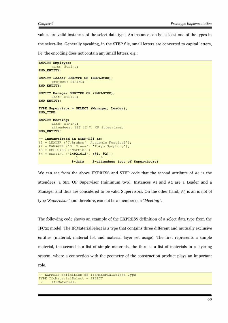
Chapter 6 Prototype Implementation
values are valid instances of the select data type. An instance can be at least one of the types in
the select-list. Generally speaking, in the STEP file, small letters are converted to capital letters,
i.e. the encoding does not contain any small letters. e.g.:
ENTITY Employee;name: String;
END_ENTITY;
ENTITY Leader SUBTYPE OF (EMPLOYEE);project: STRING;
END_ENTITY;
ENTITY Manager SUBTYPE OF (EMPLOYEE);unit: STRING;
END_ENTITY;
TYPE Supervisor = SELECT (Manager, Leader);
END_TYPE;
ENTITY Meeting;date: STRING;
attendees: SET [2:?] OF Supervisor;
END_ENTITY;
-- Instantiated in STEP-P21 as:#1 = LEADER ('J.Brahms', Academic Festival');
#2 = MANAGER ('S. Ozawa', 'Tokyo Symphony');
#3 = EMPLOYEE ('Martin');
#4 = MEETING ('14921012', (#1, #2));
^ ^
1-date 2-attendees (set of Supervisors)
We can see from the above EXPRESS and STEP code that the second attribute of #4 is the
attendees: a SET OF Supervisor (minimum two). Instances #1 and #2 are a Leader and a
Manager and thus are considered to be valid Supervisors. On the other hand, #3 is an is not of
type “Supervisor” and therefore, can not be a member of a “Meeting”.
The following code shows an example of the EXPRESS definition of a select data type from the
IFC2x model. The IfcMaterialSelect is a type that contains three different and mutually exclusive
entities (material, material list and material layer set usage). The first represents a simple
material, the second is a list of simple materials, the third is a list of materials in a layering
system, where a connection with the geometry of the construction product plays an important
role.
-- EXPRESS definition of IfcMaterialSelect Type
TYPE IfcMaterialSelect = SELECT
( IfcMaterial,
90
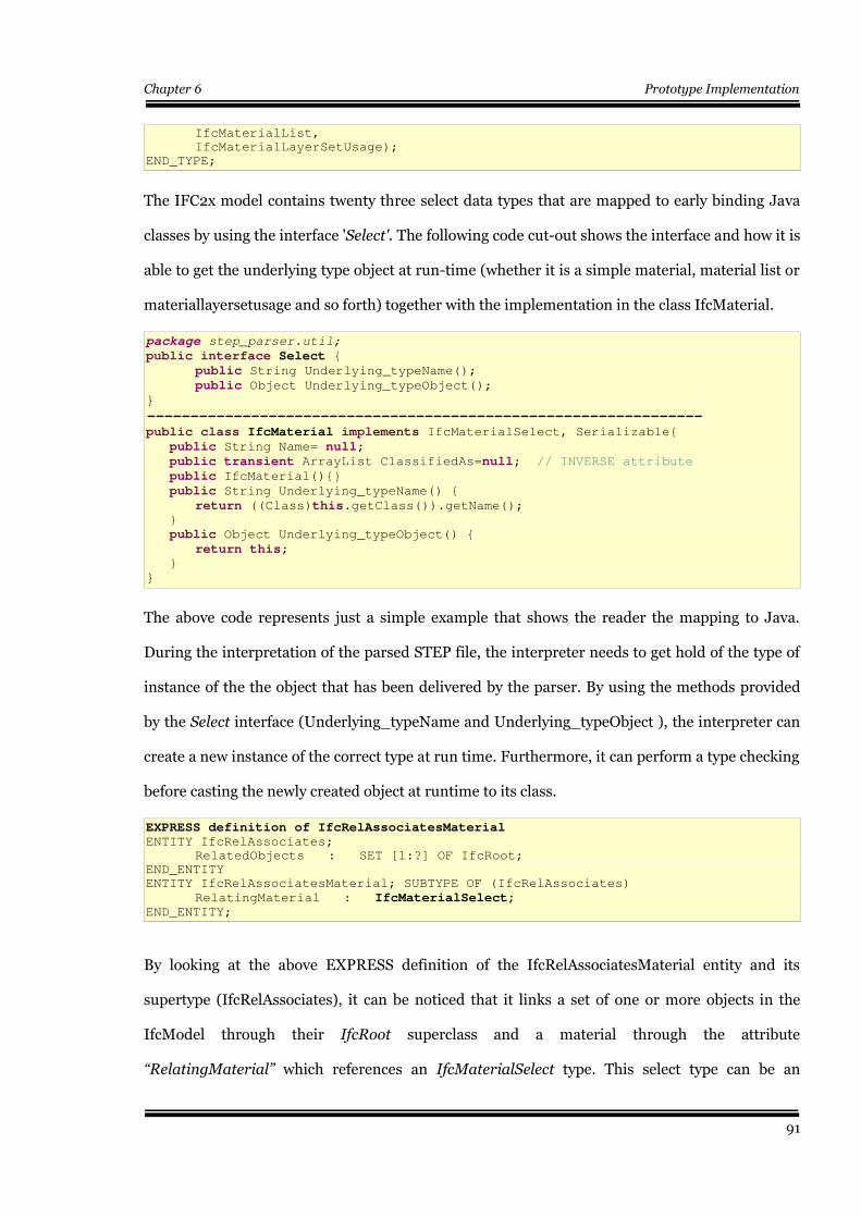
Chapter 6 Prototype Implementation
IfcMaterialList,
IfcMaterialLayerSetUsage);
END_TYPE;
The IFC2x model contains twenty three select data types that are mapped to early binding Java
classes by using the interface 'Select'. The following code cut-out shows the interface and how it is
able to get the underlying type object at run-time (whether it is a simple material, material list or
materiallayersetusage and so forth) together with the implementation in the class IfcMaterial.
package step_parser.util;
public interface Select {
public String Underlying_typeName();
public Object Underlying_typeObject();
}
----------------------------------------------------------------
public class IfcMaterial implements IfcMaterialSelect, Serializable{
public String Name= null;
public transient ArrayList ClassifiedAs=null; // INVERSE attribute
public IfcMaterial(){}
public String Underlying_typeName() {
return ((Class)this.getClass()).getName(); }
public Object Underlying_typeObject() {
return this; }
}
The above code represents just a simple example that shows the reader the mapping to Java.
During the interpretation of the parsed STEP file, the interpreter needs to get hold of the type of
instance of the the object that has been delivered by the parser. By using the methods provided
by the Select interface (Underlying_typeName and Underlying_typeObject ), the interpreter can
create a new instance of the correct type at run time. Furthermore, it can perform a type checking
before casting the newly created object at runtime to its class.
EXPRESS definition of IfcRelAssociatesMaterialENTITY IfcRelAssociates;
RelatedObjects : SET [1:?] OF IfcRoot;
END_ENTITY
ENTITY IfcRelAssociatesMaterial; SUBTYPE OF (IfcRelAssociates)
RelatingMaterial : IfcMaterialSelect;END_ENTITY;
By looking at the above EXPRESS definition of the IfcRelAssociatesMaterial entity and its
supertype (IfcRelAssociates), it can be noticed that it links a set of one or more objects in the
IfcModel through their IfcRoot superclass and a material through the attribute
“RelatingMaterial” which references an IfcMaterialSelect type. This select type can be an
91
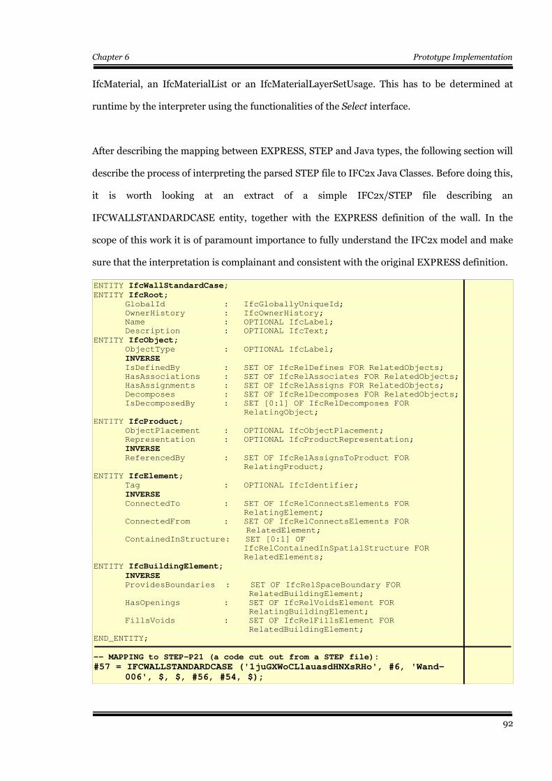
Chapter 6 Prototype Implementation
IfcMaterial, an IfcMaterialList or an IfcMaterialLayerSetUsage. This has to be determined at
runtime by the interpreter using the functionalities of the Select interface.
After describing the mapping between EXPRESS, STEP and Java types, the following section will
describe the process of interpreting the parsed STEP file to IFC2x Java Classes. Before doing this,
it is worth looking at an extract of a simple IFC2x/STEP file describing an
IFCWALLSTANDARDCASE entity, together with the EXPRESS definition of the wall. In the
scope of this work it is of paramount importance to fully understand the IFC2x model and make
sure that the interpretation is complainant and consistent with the original EXPRESS definition.
ENTITY IfcWallStandardCase;
ENTITY IfcRoot;GlobalId : IfcGloballyUniqueId;
OwnerHistory : IfcOwnerHistory;
Name : OPTIONAL IfcLabel;
Description : OPTIONAL IfcText;
ENTITY IfcObject;ObjectType : OPTIONAL IfcLabel;
INVERSEIsDefinedBy : SET OF IfcRelDefines FOR RelatedObjects;
HasAssociations : SET OF IfcRelAssociates FOR RelatedObjects;
HasAssignments : SET OF IfcRelAssigns FOR RelatedObjects;
Decomposes : SET OF IfcRelDecomposes FOR RelatedObjects;
IsDecomposedBy : SET [0:1] OF IfcRelDecomposes FOR
RelatingObject;
ENTITY IfcProduct;ObjectPlacement : OPTIONAL IfcObjectPlacement;
Representation : OPTIONAL IfcProductRepresentation;
INVERSEReferencedBy : SET OF IfcRelAssignsToProduct FOR
RelatingProduct;
ENTITY IfcElement; Tag : OPTIONAL IfcIdentifier;
INVERSE ConnectedTo : SET OF IfcRelConnectsElements FOR
RelatingElement;
ConnectedFrom : SET OF IfcRelConnectsElements FOR
RelatedElement;
ContainedInStructure: SET [0:1] OF
IfcRelContainedInSpatialStructure FOR
RelatedElements;
ENTITY IfcBuildingElement;
INVERSEProvidesBoundaries : SET OF IfcRelSpaceBoundary FOR
RelatedBuildingElement;
HasOpenings : SET OF IfcRelVoidsElement FOR
RelatingBuildingElement;
FillsVoids : SET OF IfcRelFillsElement FOR
RelatedBuildingElement;
END_ENTITY;
-- MAPPING to STEP-P21 (a code cut out from a STEP file):
#57 = IFCWALLSTANDARDCASE ('1juGXWoCL1auasdHNXsRHo', #6, 'Wand-006', $, $, #56, #54, $);
92
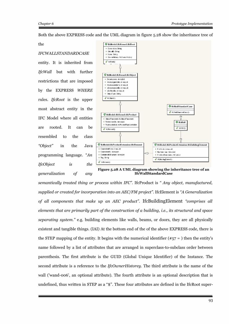
Chapter 6 Prototype Implementation
Both the above EXPRESS code and the UML diagram in figure 5.28 show the inheritance tree of
the
IFCWALLSTANDARDCASE
entity. It is inherited from
IfcWall but with further
restrictions that are imposed
by the EXPRESS WHERE
rules. IfcRoot is the upper
most abstract entity in the
IFC Model where all entities
are rooted. It can be
resembled to the class
“Object” in the Java
programming language. “An
IfcObject is the
generalization of any
semantically treated thing or process within IFC”. IfcProduct is “ Any object, manufactured,
supplied or created for incorporation into an AEC/FM project”. IfcElement is “A Generalization
of all components that make up an AEC product”. IfcBuildingElement “comprises all
elements that are primarily part of the construction of a building, i.e., its structural and space
separating system.” e.g. building elements like walls, beams, or doors, they are all physically
existent and tangible things. (IAI) At the bottom end of the of the above EXPRESS code, there is
the STEP mapping of the entity. It begins with the numerical identifier (#57 = ) then the entity's
name followed by a list of attributes that are arranged in superclass-to-subclass order between
parenthesis. The first attribute is the GUID (Global Unique Identifier) of the Instance. The
second attribute is a reference to the IfcOwnerHistorey. The third attribute is the name of the
wall ('wand-006', an optional attribute). The fourth attribute is an optional description that is
undefined, thus written in STEP as a “$”. These four attributes are defined in the IfcRoot super-
93
Figure 5.28 A UML diagram showing the inheritance tree of anIfcWallStandardCase

Chapter 6 Prototype Implementation
type. The fifth attribute is an optional label attribute that belongs to the IfcObject supertype and
is undefined and written as a “$”. #56 and #54 are references to the positioning and graphical
representation of the wall respectively. They are the two attributes of the superclass IfcProduct,
where each product in the IFC model should have a location in the coordinate space and at least
one geometrical representation. These issues will be discussed later in this work in detail in the
visualization section.
By looking at both the previous EXPRESS code and the STEP mapping. The following
observations can be noticed:
1- The optional attributes of the EXPRESS language may and may not be instantiated
in the STEP physical file. If they are not, they are represented by the '$' symbol, which
in turn has to be translated to a null reference in Java.
2- Both the Inverse and the Derived attributes are not mapped to the STEP file.
(similar to transient and static attributes in Java). It should also be noticed that the
IFC model relies very heavily on the Inverse attributes in creating references between
objects and the relations in the IfcKernel and their sub-types. Hence alternative
means of reaching the attributes has to be established to be able to conduct any
queries in the model.
3- The references between objects are established through IDs that are represented by
a numerical identifier preceded by a '#'.
4- Container classes (Sets, List, Arrays and Bags) are represented by arguments that
are nested between extra parenthesis.
By analyzing the STEP/IFC code in appendix A1, we can see how the file describes the wall. IFC
files usually begin with defining the measuring units as seen in section 1 of the code. Section 2
shows the definition of the materials that are later related to the wall. Section 3 shows the
relations that join the project constituents together (aggregation relations) as shown in figure
5.37; Project to Sites, each site to its Buildings, each Building to its Building Stories and each
94
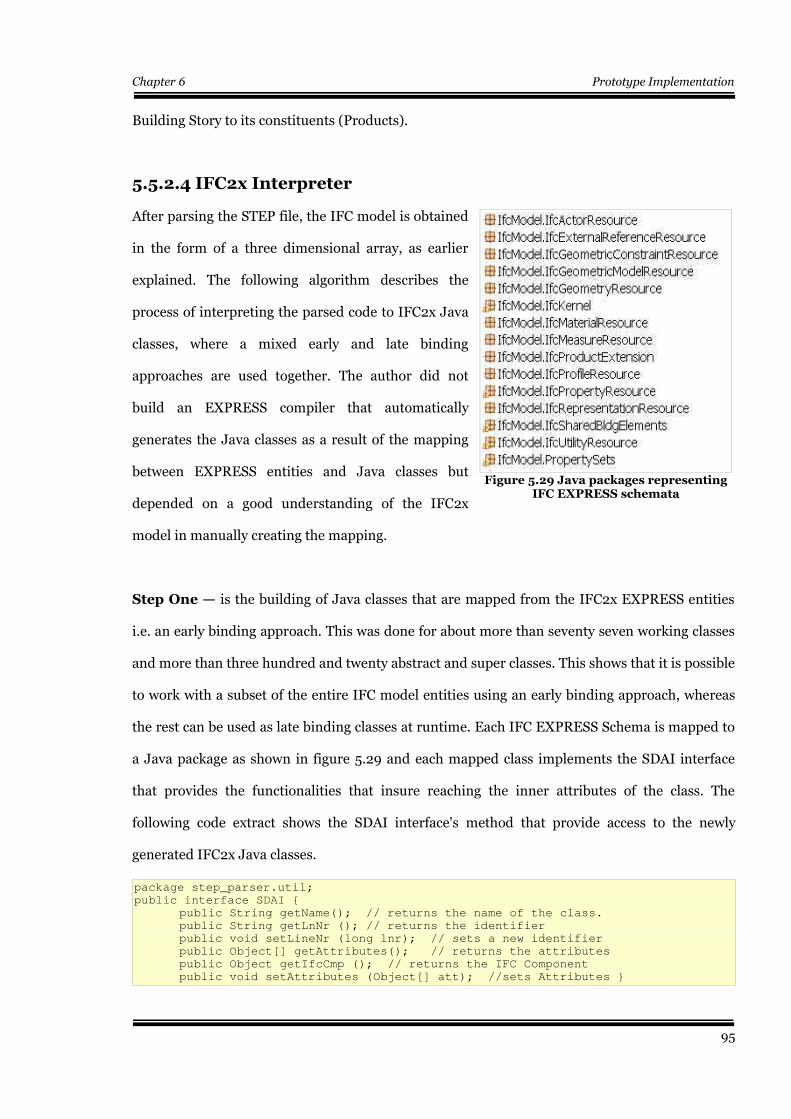
Chapter 6 Prototype Implementation
Building Story to its constituents (Products).
5.5.2.4 IFC2x Interpreter
After parsing the STEP file, the IFC model is obtained
in the form of a three dimensional array, as earlier
explained. The following algorithm describes the
process of interpreting the parsed code to IFC2x Java
classes, where a mixed early and late binding
approaches are used together. The author did not
build an EXPRESS compiler that automatically
generates the Java classes as a result of the mapping
between EXPRESS entities and Java classes but
depended on a good understanding of the IFC2x
model in manually creating the mapping.
Step One — is the building of Java classes that are mapped from the IFC2x EXPRESS entities
i.e. an early binding approach. This was done for about more than seventy seven working classes
and more than three hundred and twenty abstract and super classes. This shows that it is possible
to work with a subset of the entire IFC model entities using an early binding approach, whereas
the rest can be used as late binding classes at runtime. Each IFC EXPRESS Schema is mapped to
a Java package as shown in figure 5.29 and each mapped class implements the SDAI interface
that provides the functionalities that insure reaching the inner attributes of the class. The
following code extract shows the SDAI interface's method that provide access to the newly
generated IFC2x Java classes.
package step_parser.util;
public interface SDAI {
public String getName(); // returns the name of the class.
public String getLnNr (); // returns the identifier
public void setLineNr (long lnr); // sets a new identifier
public Object[] getAttributes(); // returns the attributes
public Object getIfcCmp (); // returns the IFC Component
public void setAttributes (Object[] att); //sets Attributes }
95
Figure 5.29 Java packages representingIFC EXPRESS schemata
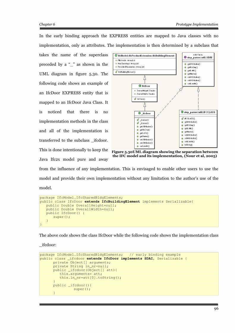
Chapter 6 Prototype Implementation
In the early binding approach the EXPRESS entities are mapped to Java classes with no
implementation, only as attributes. The implementation is then determined by a subclass that
takes the name of the superclass
preceded by a “_” as shown in the
UML diagram in figure 5.30. The
following code shows an example of
an IfcDoor EXPRESS entity that is
mapped to an IfcDoor Java Class. It
is noticed that there is no
implementation methods in the class
and all of the implementation is
transferred to the subclass _ifcdoor.
This is done intentionally to keep the
Java Ifc2x model pure and away
from the influence of any implementation. This is envisaged to enable other users to use the
model and provide their own implementation without any limitation to the author's use of the
model.
package IfcModel.IfcSharedBldgElements;
public class IfcDoor extends IfcBuildingElement implements Serializable{ public Double OverallHeight=null;
public Double OverallWidth=null;
public IfcDoor() {
super();
}
}
The above code shows the class IfcDoor while the following code shows the implementation class
_ifcdoor:
package IfcModel.IfcSharedBldgElements; // early binding example
public class _ifcdoor extends IfcDoor implements SDAI, Serializable {private Object[] arguments;
private String ln_nr=null;
public _ifcdoor(Object[] att){
this.arguments= att;
this.ln_nr=att[0].toString();
}
public _ifcdoor(){
super();
}
96
Figure 5.30UML diagram showing the separation betweenthe IFC model and its implementation, (Nour et al, 2005)
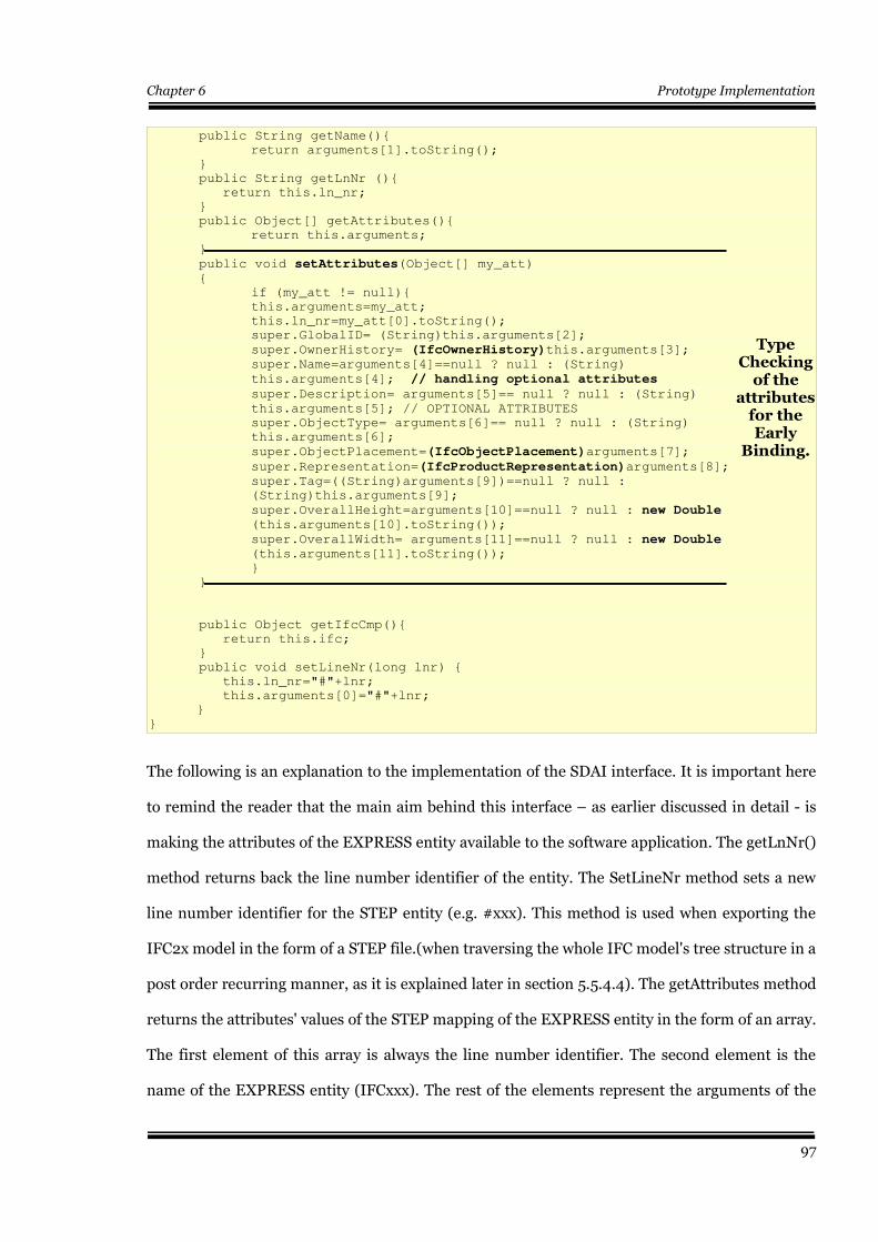
Chapter 6 Prototype Implementation
public String getName(){
return arguments[1].toString();
}
public String getLnNr (){
return this.ln_nr;
}
public Object[] getAttributes(){
return this.arguments;
}
public void setAttributes(Object[] my_att) {
if (my_att != null){
this.arguments=my_att;
this.ln_nr=my_att[0].toString();
super.GlobalID= (String)this.arguments[2];
super.OwnerHistory= (IfcOwnerHistory)this.arguments[3]; super.Name=arguments[4]==null ? null : (String)
this.arguments[4]; // handling optional attributes
super.Description= arguments[5]== null ? null : (String)
this.arguments[5]; // OPTIONAL ATTRIBUTES
super.ObjectType= arguments[6]== null ? null : (String)
this.arguments[6];
super.ObjectPlacement=(IfcObjectPlacement)arguments[7];
super.Representation=(IfcProductRepresentation)arguments[8];super.Tag=((String)arguments[9])==null ? null :
(String)this.arguments[9];
super.OverallHeight=arguments[10]==null ? null : new Double (this.arguments[10].toString());
super.OverallWidth= arguments[11]==null ? null : new Double(this.arguments[11].toString());
}
}
public Object getIfcCmp(){
return this.ifc;
}
public void setLineNr(long lnr) {
this.ln_nr="#"+lnr;
this.arguments[0]="#"+lnr;
}
}
The following is an explanation to the implementation of the SDAI interface. It is important here
to remind the reader that the main aim behind this interface – as earlier discussed in detail - is
making the attributes of the EXPRESS entity available to the software application. The getLnNr()
method returns back the line number identifier of the entity. The SetLineNr method sets a new
line number identifier for the STEP entity (e.g. #xxx). This method is used when exporting the
IFC2x model in the form of a STEP file.(when traversing the whole IFC model's tree structure in a
post order recurring manner, as it is explained later in section 5.5.4.4). The getAttributes method
returns the attributes' values of the STEP mapping of the EXPRESS entity in the form of an array.
The first element of this array is always the line number identifier. The second element is the
name of the EXPRESS entity (IFCxxx). The rest of the elements represent the arguments of the
97
Type Checking
of the attributes
for theEarly
Binding.
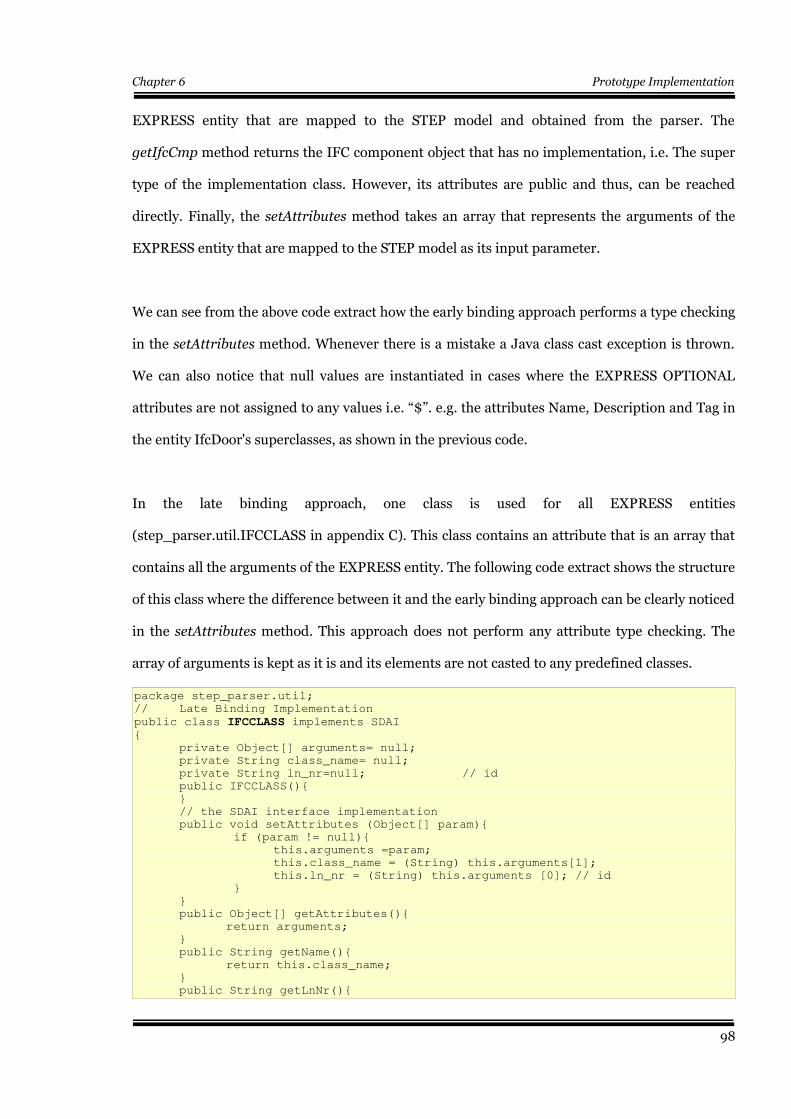
Chapter 6 Prototype Implementation
EXPRESS entity that are mapped to the STEP model and obtained from the parser. The
getIfcCmp method returns the IFC component object that has no implementation, i.e. The super
type of the implementation class. However, its attributes are public and thus, can be reached
directly. Finally, the setAttributes method takes an array that represents the arguments of the
EXPRESS entity that are mapped to the STEP model as its input parameter.
We can see from the above code extract how the early binding approach performs a type checking
in the setAttributes method. Whenever there is a mistake a Java class cast exception is thrown.
We can also notice that null values are instantiated in cases where the EXPRESS OPTIONAL
attributes are not assigned to any values i.e. “$”. e.g. the attributes Name, Description and Tag in
the entity IfcDoor's superclasses, as shown in the previous code.
In the late binding approach, one class is used for all EXPRESS entities
(step_parser.util.IFCCLASS in appendix C). This class contains an attribute that is an array that
contains all the arguments of the EXPRESS entity. The following code extract shows the structure
of this class where the difference between it and the early binding approach can be clearly noticed
in the setAttributes method. This approach does not perform any attribute type checking. The
array of arguments is kept as it is and its elements are not casted to any predefined classes.
package step_parser.util;
// Late Binding Implementation
public class IFCCLASS implements SDAI{
private Object[] arguments= null;
private String class_name= null;
private String ln_nr=null; // id
public IFCCLASS(){
}
// the SDAI interface implementation
public void setAttributes (Object[] param){
if (param != null){
this.arguments =param;
this.class_name = (String) this.arguments[1];
this.ln_nr = (String) this.arguments [0]; // id
}
}
public Object[] getAttributes(){
return arguments;
}
public String getName(){
return this.class_name;
}
public String getLnNr(){
98
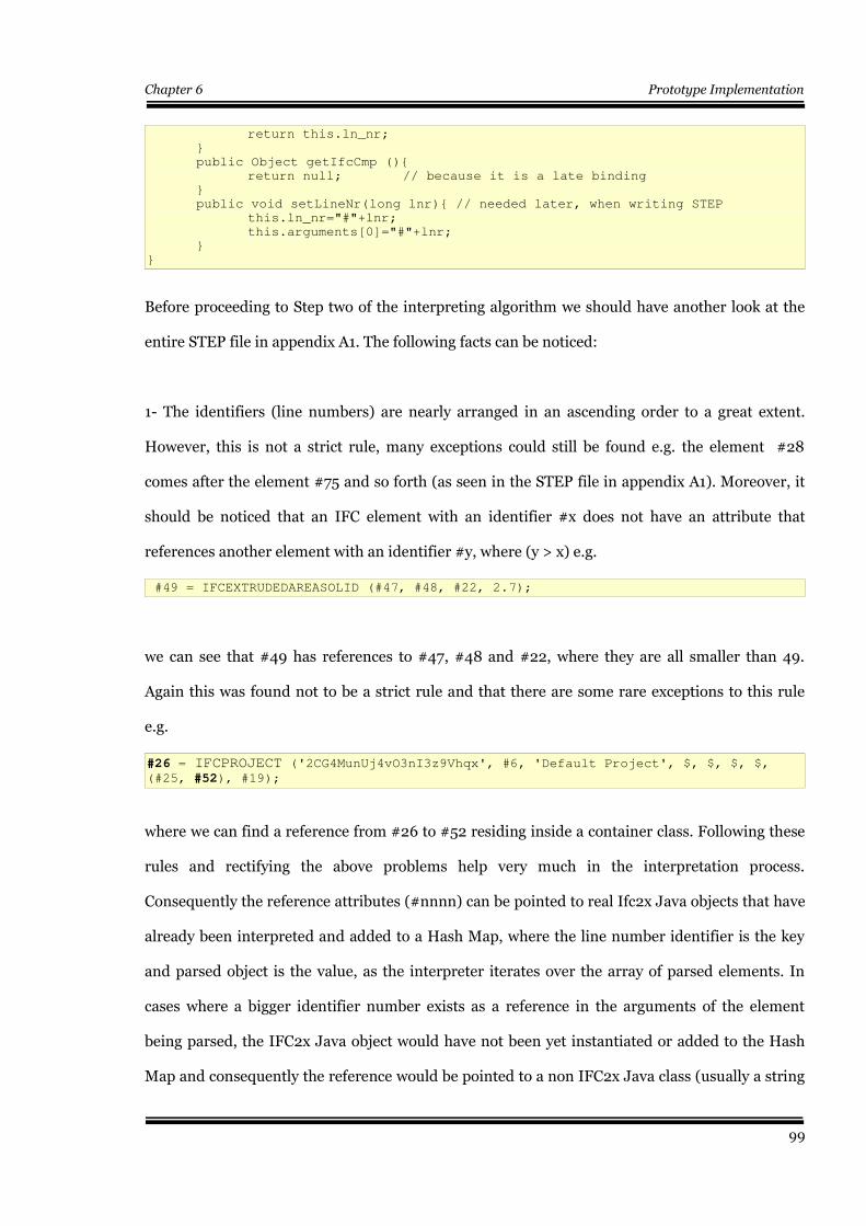
Chapter 6 Prototype Implementation
return this.ln_nr;
}
public Object getIfcCmp (){
return null; // because it is a late binding
}
public void setLineNr(long lnr){ // needed later, when writing STEP
this.ln_nr="#"+lnr;
this.arguments[0]="#"+lnr;
}
}
Before proceeding to Step two of the interpreting algorithm we should have another look at the
entire STEP file in appendix A1. The following facts can be noticed:
1- The identifiers (line numbers) are nearly arranged in an ascending order to a great extent.
However, this is not a strict rule, many exceptions could still be found e.g. the element #28
comes after the element #75 and so forth (as seen in the STEP file in appendix A1). Moreover, it
should be noticed that an IFC element with an identifier #x does not have an attribute that
references another element with an identifier #y, where (y > x) e.g.
#49 = IFCEXTRUDEDAREASOLID (#47, #48, #22, 2.7);
we can see that #49 has references to #47, #48 and #22, where they are all smaller than 49.
Again this was found not to be a strict rule and that there are some rare exceptions to this rule
e.g.
#26 = IFCPROJECT ('2CG4MunUj4vO3nI3z9Vhqx', #6, 'Default Project', $, $, $, $,(#25, #52), #19);
where we can find a reference from #26 to #52 residing inside a container class. Following these
rules and rectifying the above problems help very much in the interpretation process.
Consequently the reference attributes (#nnnn) can be pointed to real Ifc2x Java objects that have
already been interpreted and added to a Hash Map, where the line number identifier is the key
and parsed object is the value, as the interpreter iterates over the array of parsed elements. In
cases where a bigger identifier number exists as a reference in the arguments of the element
being parsed, the IFC2x Java object would have not been yet instantiated or added to the Hash
Map and consequently the reference would be pointed to a non IFC2x Java class (usually a string
99
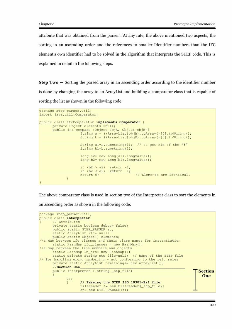
Chapter 6 Prototype Implementation
attribute that was obtained from the parser). At any rate, the above mentioned two aspects; the
sorting in an ascending order and the references to smaller Identifier numbers than the IFC
element's own identifier had to be solved in the algorithm that interprets the STEP code. This is
explained in detail in the following steps.
Step Two — Sorting the parsed array in an ascending order according to the identifier number
is done by changing the array to an ArrayList and building a comparator class that is capable of
sorting the list as shown in the following code:
package step_parser.util;
import java.util.Comparator;
public class IfcComparator implements Comparator {
private Object elements =null;
public int compare (Object objA, Object objB){
String a = ((ArrayList)objA).toArray()[0].toString();
String b = ((ArrayList)objB).toArray()[0].toString();
String a1=a.substring(1); // to get rid of the “#”
String b1=b.substring(1);
long a2= new Long(a1).longValue();
long b2= new Long(b1).longValue();
if (b2 > a2) return -1;
if (b2 < a2) return 1;
return 0; // Elements are identical.
}
}
The above comparator class is used in section two of the Interpreter class to sort the elements in
an ascending order as shown in the following code:
package step_parser.util;
public class Interpreter { // Attributes
private static boolean debug= false;
public static STEP_PARSER st;
static ArrayList ifc= null;
public static Object[] elements;
//a Map between ifc_classes and their class names for instantiation
static HashMap ifc_classes = new HashMap();
//a map between the line numbers and objects
static HashMap ln_nrs= new HashMap();
static private String stp_file=null; // name of the STEP file
// for handling wrong numbering – not conforming to the ref. rules
private static ArrayList remainings= new ArrayList();
//Section One__________________________________________________public Interpreter ( String _stp_file)
{
try
{ // Parsing the STEP ISO 10303-P21 fileFileReader f= new FileReader(_stp_file);
st= new STEP_PARSER(f);
100
Section One

Chapter 6 Prototype Implementation
st.ReInit(f);
st.start(); // starting the parser
ifc = st.ifcX;//getting the ArrayList from the parser
//Section Two_____________________________________________// 1st Step--- Sorting the ArrayList ifc using the
// IFC comparetor comp
IfcComparator comp= new IfcComparator();
Collections.sort(ifc, comp);elements=ifc.toArray();//getting the array of objects
}
catch (Exception e){
...
}
//Section Three adding the early binding classes___________try
{
add_class ("IFCCLASS", Class.forName //Late B. Class("step_parser.util.IFCCLASS"));
add_class ("_ifcorganization",Class.forName
("IfcModel.IfcActorResource._ifcorganization"));
add_class ("_ifccartesianpoint",Class.forName
("IfcModel.IfcGeometryResource._ifccartesianpoint"));
add_class ("_ifclocalplacement", Class.forName
add_class ("_ifcbuilding", Class.forName
("IfcModel.IfcProductExtension._ifcbuilding"));
//...
// Instantiationg the IFC2x model________________________
instantiate();
} //_____________________________________________________ catch (Exception e1) {
...
}
}
//Section Four__________________________________________________
public void instantiate() throws InstantiationException, IllegalAccessException
{
Object[] arguments;
for (int i=0; i<elements.length; i++)
{
arguments= ((ArrayList)elements[i]).toArray();
String class_name= ((String) arguments[1]).
toLowerCase();
Class ifcClass = (Class) ifc_classes.get
("_"+class_name);
if (ifcClass == null)
{
if (debug) System.out.println("Class is not
yet added, it will be casted to the IFCCLASS:
" + class_name); // late bindingtry
{
ifcClass= (Class) ifc_classes.get
("IFCCLASS");
if (ifcClass !=null)
{
IFCCLASS ifc= (IFCCLASS)
ifcClass.newInstance();
ifc.setAttributes( arguments, new
Ln_Map());
elements[i]=checkIFC(ifc,
remainings);
ln_nrs.put(((SDAI)elements[i]).getLnNr(), elements[i]);
}
else
{
System.err.print("Permenant
101
Section Two
Section Four
Section Three
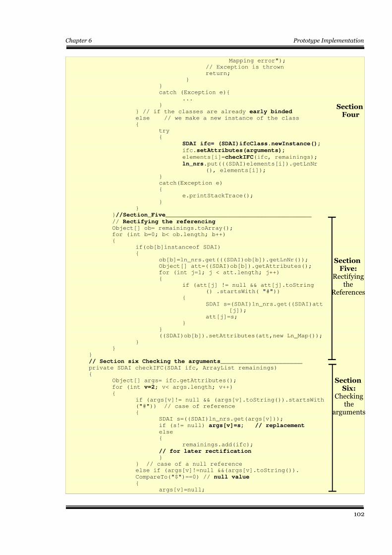
Chapter 6 Prototype Implementation
Mapping error");
// Exception is thrown
return;
}
}
catch (Exception e){
...
}
} // if the classes are already early binded else // we make a new instance of the class
{
try
{
SDAI ifc= (SDAI)ifcClass.newInstance();
ifc.setAttributes(arguments);
elements[i]=checkIFC(ifc, remainings);
ln_nrs.put(((SDAI)elements[i]).getLnNr(), elements[i]);
}
catch(Exception e)
{
e.printStackTrace();
}
}
}//Section_Five_________________________________________
// Rectifying the referencingObject[] ob= remainings.toArray();
for (int b=0; b< ob.length; b++)
{
if(ob[b]instanceof SDAI)
{
ob[b]=ln_nrs.get(((SDAI)ob[b]).getLnNr());
Object[] att=((SDAI)ob[b]).getAttributes();
for (int j=1; j < att.length; j++)
{
if (att[j] != null && att[j].toString
() .startsWith( "#"))
{
SDAI s=(SDAI)ln_nrs.get((SDAI)att
[j]);
att[j]=s;
}
}
((SDAI)ob[b]).setAttributes(att,new Ln_Map());
}
}
}
// Section six Checking the arguments_______________________private SDAI checkIFC(SDAI ifc, ArrayList remainings)
{
Object[] args= ifc.getAttributes();
for (int v=2; v< args.length; v++){
if (args[v]!= null && (args[v].toString()).startsWith
("#")) // case of reference
{
SDAI s=((SDAI)ln_nrs.get(args[v]));
if (s!= null) args[v]=s; // replacementelse
{
remainings.add(ifc);
// for later rectification}
} // case of a null reference
else if (args[v]!=null &&(args[v].toString()).
CompareTo("$")==0) // null value {
args[v]=null;
102
Section Four
Section Five:
Rectifying the
References
Section Six:
Checking the
arguments
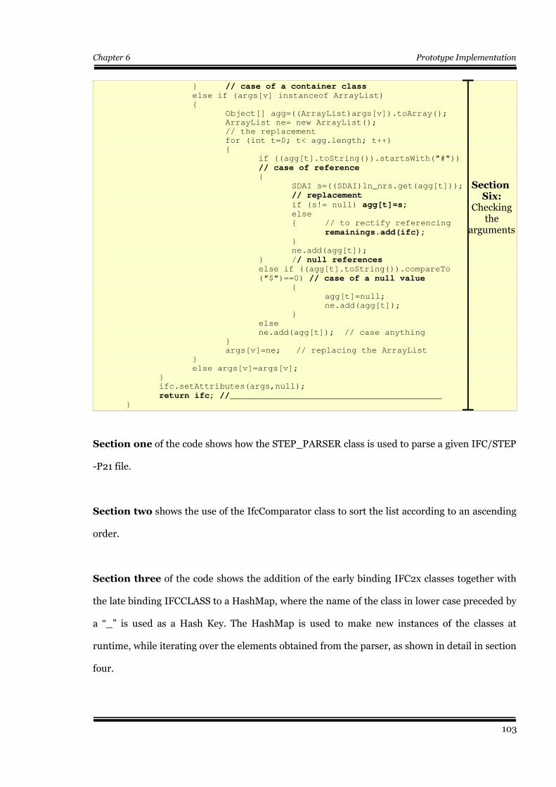
Chapter 6 Prototype Implementation
} // case of a container classelse if (args[v] instanceof ArrayList)
{
Object[] agg=((ArrayList)args[v]).toArray();
ArrayList ne= new ArrayList();
// the replacement
for (int t=0; t< agg.length; t++)
{
if ((agg[t].toString()).startsWith("#"))
// case of reference{
SDAI s=((SDAI)ln_nrs.get(agg[t]));
// replacement
if (s!= null) agg[t]=s; else
{ // to rectify referencing
remainings.add(ifc);}
ne.add(agg[t]);
} // null referenceselse if ((agg[t].toString()).compareTo
("$")==0) // case of a null value{
agg[t]=null;
ne.add(agg[t]);
}
else
ne.add(agg[t]); // case anything
}
args[v]=ne; // replacing the ArrayList
}
else args[v]=args[v];
}
ifc.setAttributes(args,null);
return ifc; //__________________________________________}
Section one of the code shows how the STEP_PARSER class is used to parse a given IFC/STEP
-P21 file.
Section two shows the use of the IfcComparator class to sort the list according to an ascending
order.
Section three of the code shows the addition of the early binding IFC2x classes together with
the late binding IFCCLASS to a HashMap, where the name of the class in lower case preceded by
a “_” is used as a Hash Key. The HashMap is used to make new instances of the classes at
runtime, while iterating over the elements obtained from the parser, as shown in detail in section
four.
103
Section Six:
Checking the
arguments
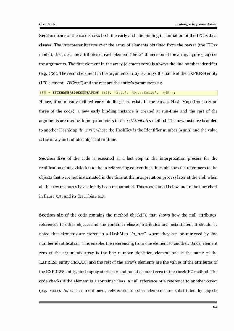
Chapter 6 Prototype Implementation
Section four of the code shows both the early and late binding instantiation of the IFC2x Java
classes. The interpreter iterates over the array of elements obtained from the parser (the IFC2x
model), then over the attributes of each element (the 2nd dimension of the array, figure 5.24) i.e.
the arguments. The first element in the array (element zero) is always the line number identifier
(e.g. #50). The second element in the arguments array is always the name of the EXPRESS entity
(IFC element, “IFCxxx”) and the rest are the entity's parameters e.g.
#50 = IFCSHAPEREPRESENTATION (#25, 'Body', 'SweptSolid', (#49));
Hence, if an already defined early binding class exists in the classes Hash Map (from section
three of the code), a new early binding instance is created at run-time and the rest of the
arguments are used as input parameters to the setAttributes method. The new instance is added
to another HashMap “ln_nrs”, where the HashKey is the Identifier number (#nnn) and the value
is the newly instantiated object at runtime.
Section five of the code is executed as a last step in the interpretation process for the
rectification of any violation to the to referencing conventions. It establishes the references to the
objects that were not instantiated in due time at the interpretation process later at the end, when
all the new instances have already been instantiated. This is explained below and in the flow chart
in figure 5.31 and its describing text.
Section six of the code contains the method checkIFC that shows how the null attributes,
references to other objects and the container classes’ attributes are instantiated. It should be
noted that elements are stored in a HashMap “ln_nrs”, where they can be retrieved by line
number identification. This enables the referencing from one element to another. Since, element
zero of the arguments array is the line number identifier, element one is the name of the
EXPRESS entity (IfcXXX) and the rest of the array’s elements are the values of the attributes of
the EXPRESS entity, the looping starts at 2 and not at element zero in the checkIFC method. The
code checks if the element is a container class, a null reference or a reference to another object
(e.g. #xxx). As earlier mentioned, references to other elements are substituted by objects
104
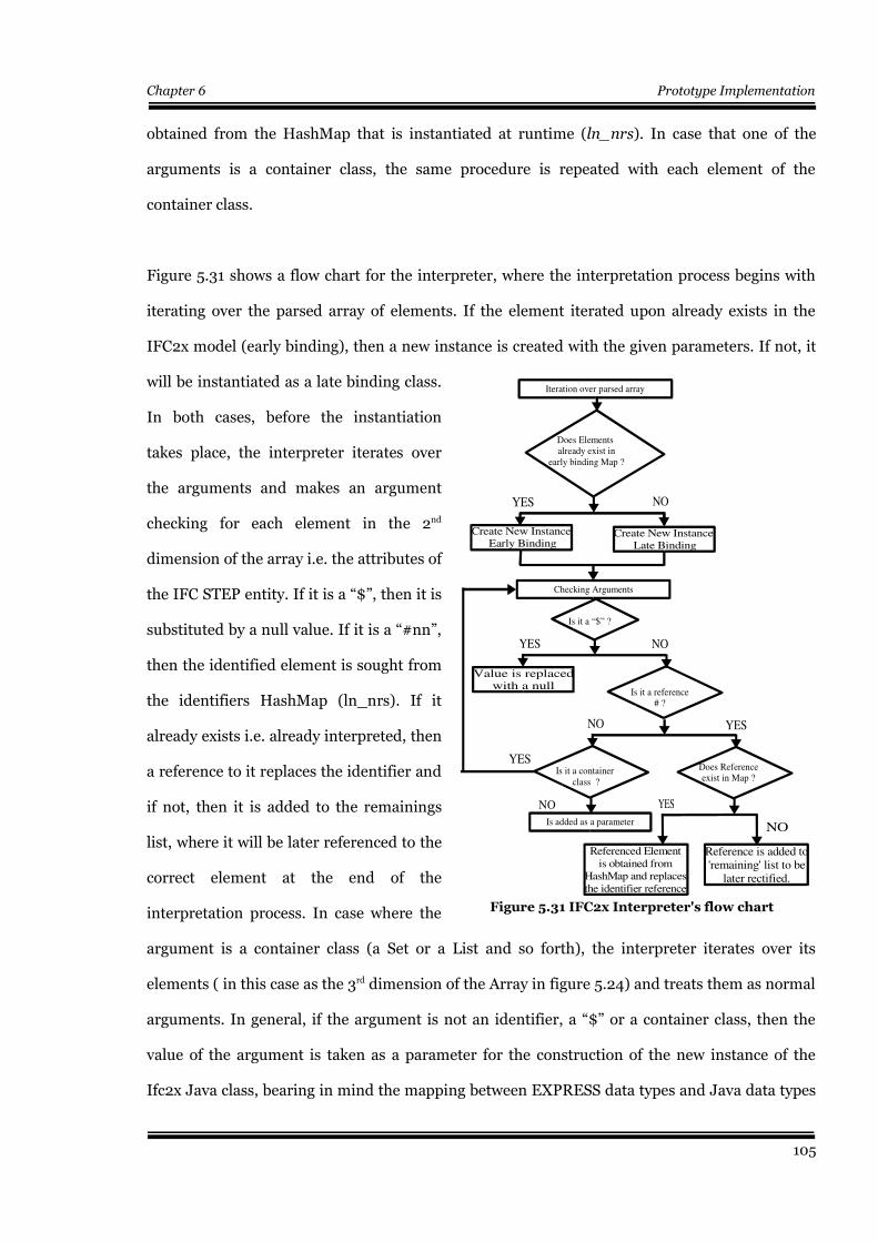
Chapter 6 Prototype Implementation
obtained from the HashMap that is instantiated at runtime (ln_nrs). In case that one of the
arguments is a container class, the same procedure is repeated with each element of the
container class.
Figure 5.31 shows a flow chart for the interpreter, where the interpretation process begins with
iterating over the parsed array of elements. If the element iterated upon already exists in the
IFC2x model (early binding), then a new instance is created with the given parameters. If not, it
will be instantiated as a late binding class.
In both cases, before the instantiation
takes place, the interpreter iterates over
the arguments and makes an argument
checking for each element in the 2nd
dimension of the array i.e. the attributes of
the IFC STEP entity. If it is a “$”, then it is
substituted by a null value. If it is a “#nn”,
then the identified element is sought from
the identifiers HashMap (ln_nrs). If it
already exists i.e. already interpreted, then
a reference to it replaces the identifier and
if not, then it is added to the remainings
list, where it will be later referenced to the
correct element at the end of the
interpretation process. In case where the
argument is a container class (a Set or a List and so forth), the interpreter iterates over its
elements ( in this case as the 3rd dimension of the Array in figure 5.24) and treats them as normal
arguments. In general, if the argument is not an identifier, a “$” or a container class, then the
value of the argument is taken as a parameter for the construction of the new instance of the
Ifc2x Java class, bearing in mind the mapping between EXPRESS data types and Java data types
105
Figure 5.31 IFC2x Interpreter's flow chart
NO
Reference is added to'remaining' list to be
later rectified.
YES
NO
Does Referenceexist in Map ?
Referenced Elementis obtained from
HashMap and replacesthe identifier reference
Is added as a parameter
YES
Is it a reference# ?
Is it a container class ?
NO YES
Value is replacedwith a null
NOYES
Is it a “$” ?
Checking Arguments
Create New Instance Late Binding
Create New Instance Early Binding
NOYES
Iteration over parsed array
Does Elements already exist in
early binding Map ?
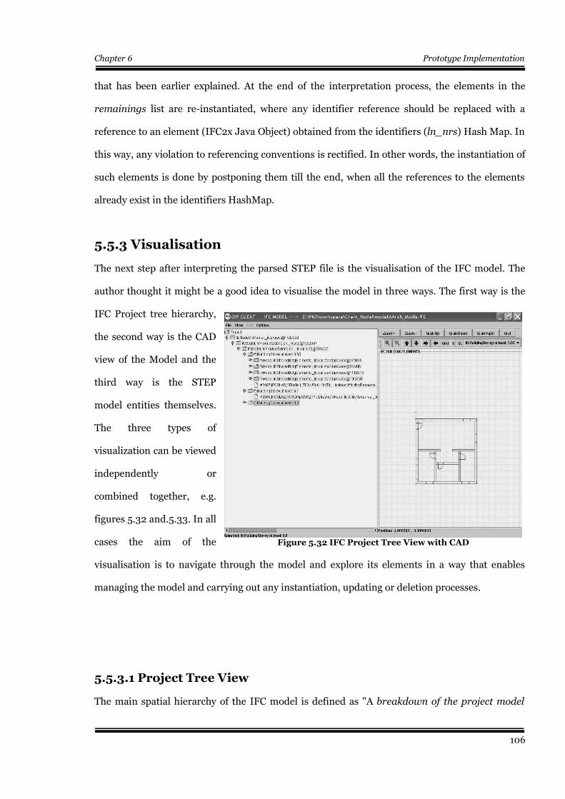
Chapter 6 Prototype Implementation
that has been earlier explained. At the end of the interpretation process, the elements in the
remainings list are re-instantiated, where any identifier reference should be replaced with a
reference to an element (IFC2x Java Object) obtained from the identifiers (ln_nrs) Hash Map. In
this way, any violation to referencing conventions is rectified. In other words, the instantiation of
such elements is done by postponing them till the end, when all the references to the elements
already exist in the identifiers HashMap.
5.5.3 Visualisation
The next step after interpreting the parsed STEP file is the visualisation of the IFC model. The
author thought it might be a good idea to visualise the model in three ways. The first way is the
IFC Project tree hierarchy,
the second way is the CAD
view of the Model and the
third way is the STEP
model entities themselves.
The three types of
visualization can be viewed
independently or
combined together, e.g.
figures 5.32 and.5.33. In all
cases the aim of the
visualisation is to navigate through the model and explore its elements in a way that enables
managing the model and carrying out any instantiation, updating or deletion processes.
5.5.3.1 Project Tree View
The main spatial hierarchy of the IFC model is defined as "A breakdown of the project model
106
Figure 5.32 IFC Project Tree View with CAD
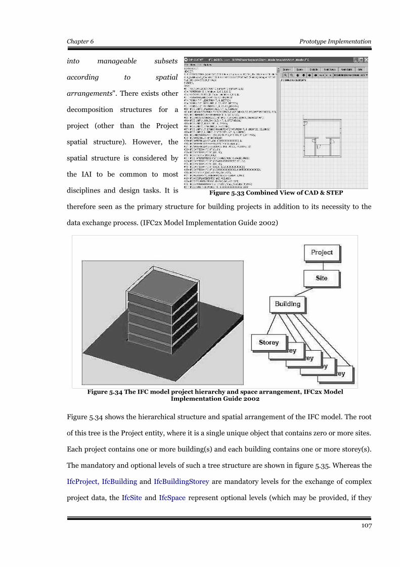
Chapter 6 Prototype Implementation
into manageable subsets
according to spatial
arrangements". There exists other
decomposition structures for a
project (other than the Project
spatial structure). However, the
spatial structure is considered by
the IAI to be common to most
disciplines and design tasks. It is
therefore seen as the primary structure for building projects in addition to its necessity to the
data exchange process. (IFC2x Model Implementation Guide 2002)
Figure 5.34 shows the hierarchical structure and spatial arrangement of the IFC model. The root
of this tree is the Project entity, where it is a single unique object that contains zero or more sites.
Each project contains one or more building(s) and each building contains one or more storey(s).
The mandatory and optional levels of such a tree structure are shown in figure 5.35. Whereas the
IfcProject, IfcBuilding and IfcBuildingStorey are mandatory levels for the exchange of complex
project data, the IfcSite and IfcSpace represent optional levels (which may be provided, if they
107
Figure 5.34 The IFC model project hierarchy and space arrangement, IFC2x ModelImplementation Guide 2002
Figure 5.33 Combined View of CAD & STEP
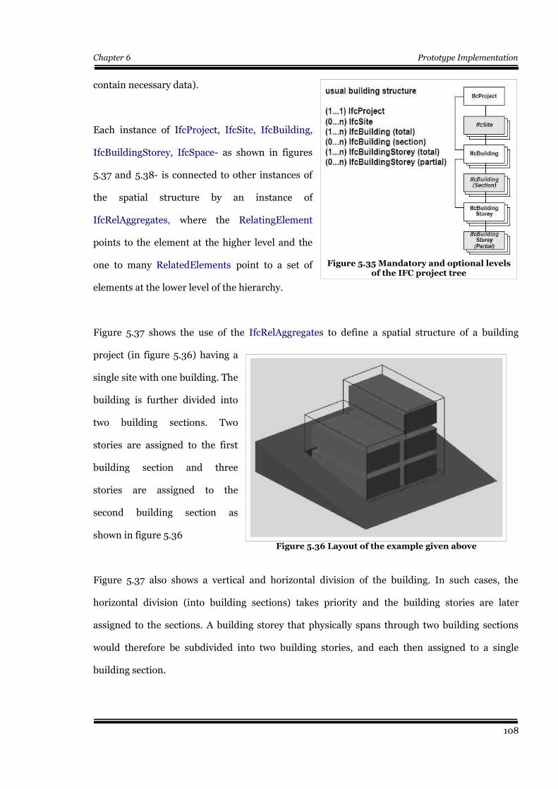
Chapter 6 Prototype Implementation
contain necessary data).
Each instance of IfcProject, IfcSite, IfcBuilding,
IfcBuildingStorey, IfcSpace- as shown in figures
5.37 and 5.38- is connected to other instances of
the spatial structure by an instance of
IfcRelAggregates, where the RelatingElement
points to the element at the higher level and the
one to many RelatedElements point to a set of
elements at the lower level of the hierarchy.
Figure 5.37 shows the use of the IfcRelAggregates to define a spatial structure of a building
project (in figure 5.36) having a
single site with one building. The
building is further divided into
two building sections. Two
stories are assigned to the first
building section and three
stories are assigned to the
second building section as
shown in figure 5.36
Figure 5.37 also shows a vertical and horizontal division of the building. In such cases, the
horizontal division (into building sections) takes priority and the building stories are later
assigned to the sections. A building storey that physically spans through two building sections
would therefore be subdivided into two building stories, and each then assigned to a single
building section.
108
Figure 5.35 Mandatory and optional levelsof the IFC project tree
Figure 5.36 Layout of the example given above
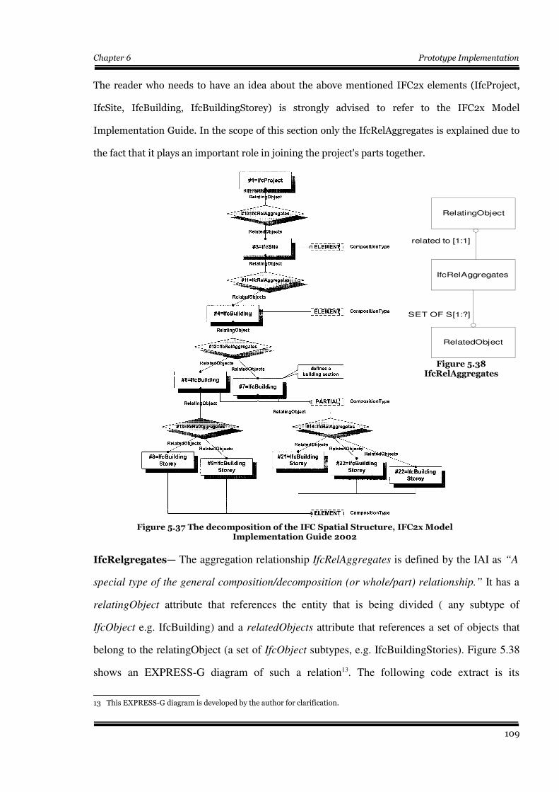
Chapter 6 Prototype Implementation
The reader who needs to have an idea about the above mentioned IFC2x elements (IfcProject,
IfcSite, IfcBuilding, IfcBuildingStorey) is strongly advised to refer to the IFC2x Model
Implementation Guide. In the scope of this section only the IfcRelAggregates is explained due to
the fact that it plays an important role in joining the project's parts together.
IfcRelgregates— The aggregation relationship IfcRelAggregates is defined by the IAI as “A
special type of the general composition/decomposition (or whole/part) relationship.” It has a
relatingObject attribute that references the entity that is being divided ( any subtype of
IfcObject e.g. IfcBuilding) and a relatedObjects attribute that references a set of objects that
belong to the relatingObject (a set of IfcObject subtypes, e.g. IfcBuildingStories). Figure 5.38
shows an EXPRESS-G diagram of such a relation13. The following code extract is its
13 This EXPRESS-G diagram is developed by the author for clarification.
109
Figure 5.37 The decomposition of the IFC Spatial Structure, IFC2x ModelImplementation Guide 2002
Figure 5.38IfcRelAggregates
RelatingObject
IfcRelAggregates
RelatedObject
SET OF S[1:?]
related to [1:1]
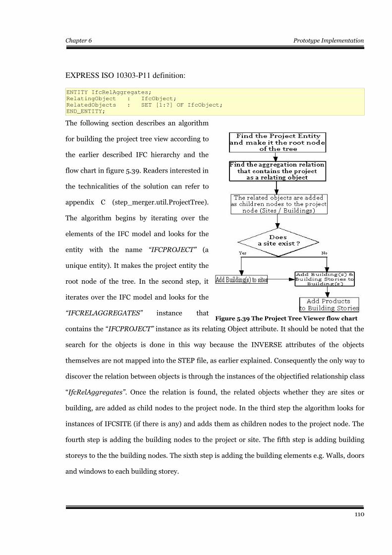
Chapter 6 Prototype Implementation
EXPRESS ISO 10303-P11 definition:
ENTITY IfcRelAggregates;
RelatingObject : IfcObject;
RelatedObjects : SET [1:?] OF IfcObject;
END_ENTITY;
The following section describes an algorithm
for building the project tree view according to
the earlier described IFC hierarchy and the
flow chart in figure 5.39. Readers interested in
the technicalities of the solution can refer to
appendix C (step_merger.util.ProjectTree).
The algorithm begins by iterating over the
elements of the IFC model and looks for the
entity with the name “IFCPROJECT” (a
unique entity). It makes the project entity the
root node of the tree. In the second step, it
iterates over the IFC model and looks for the
“IFCRELAGGREGATES” instance that
contains the “IFCPROJECT” instance as its relating Object attribute. It should be noted that the
search for the objects is done in this way because the INVERSE attributes of the objects
themselves are not mapped into the STEP file, as earlier explained. Consequently the only way to
discover the relation between objects is through the instances of the objectified relationship class
“IfcRelAggregates”. Once the relation is found, the related objects whether they are sites or
building, are added as child nodes to the project node. In the third step the algorithm looks for
instances of IFCSITE (if there is any) and adds them as children nodes to the project node. The
fourth step is adding the building nodes to the project or site. The fifth step is adding building
storeys to the the building nodes. The sixth step is adding the building elements e.g. Walls, doors
and windows to each building storey.
110
Figure 5.39 The Project Tree Viewer flow chart
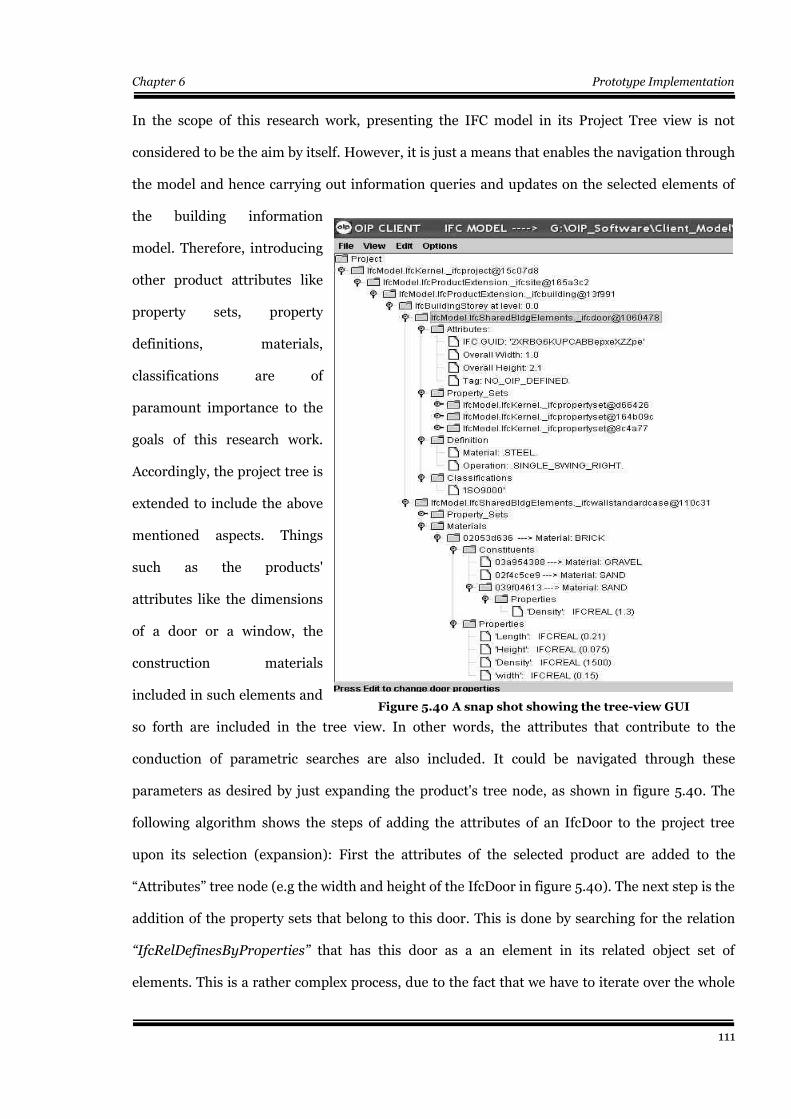
Chapter 6 Prototype Implementation
In the scope of this research work, presenting the IFC model in its Project Tree view is not
considered to be the aim by itself. However, it is just a means that enables the navigation through
the model and hence carrying out information queries and updates on the selected elements of
the building information
model. Therefore, introducing
other product attributes like
property sets, property
definitions, materials,
classifications are of
paramount importance to the
goals of this research work.
Accordingly, the project tree is
extended to include the above
mentioned aspects. Things
such as the products'
attributes like the dimensions
of a door or a window, the
construction materials
included in such elements and
so forth are included in the tree view. In other words, the attributes that contribute to the
conduction of parametric searches are also included. It could be navigated through these
parameters as desired by just expanding the product's tree node, as shown in figure 5.40. The
following algorithm shows the steps of adding the attributes of an IfcDoor to the project tree
upon its selection (expansion): First the attributes of the selected product are added to the
“Attributes” tree node (e.g the width and height of the IfcDoor in figure 5.40). The next step is the
addition of the property sets that belong to this door. This is done by searching for the relation
“IfcRelDefinesByProperties” that has this door as a an element in its related object set of
elements. This is a rather complex process, due to the fact that we have to iterate over the whole
111
Figure 5.40 A snap shot showing the tree-view GUI
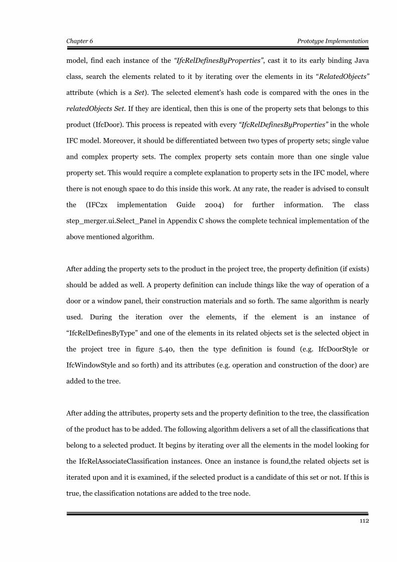
Chapter 6 Prototype Implementation
model, find each instance of the “IfcRelDefinesByProperties”, cast it to its early binding Java
class, search the elements related to it by iterating over the elements in its “RelatedObjects”
attribute (which is a Set). The selected element's hash code is compared with the ones in the
relatedObjects Set. If they are identical, then this is one of the property sets that belongs to this
product (IfcDoor). This process is repeated with every “IfcRelDefinesByProperties” in the whole
IFC model. Moreover, it should be differentiated between two types of property sets; single value
and complex property sets. The complex property sets contain more than one single value
property set. This would require a complete explanation to property sets in the IFC model, where
there is not enough space to do this inside this work. At any rate, the reader is advised to consult
the (IFC2x implementation Guide 2004) for further information. The class
step_merger.ui.Select_Panel in Appendix C shows the complete technical implementation of the
above mentioned algorithm.
After adding the property sets to the product in the project tree, the property definition (if exists)
should be added as well. A property definition can include things like the way of operation of a
door or a window panel, their construction materials and so forth. The same algorithm is nearly
used. During the iteration over the elements, if the element is an instance of
“IfcRelDefinesByType” and one of the elements in its related objects set is the selected object in
the project tree in figure 5.40, then the type definition is found (e.g. IfcDoorStyle or
IfcWindowStyle and so forth) and its attributes (e.g. operation and construction of the door) are
added to the tree.
After adding the attributes, property sets and the property definition to the tree, the classification
of the product has to be added. The following algorithm delivers a set of all the classifications that
belong to a selected product. It begins by iterating over all the elements in the model looking for
the IfcRelAssociateClassification instances. Once an instance is found,the related objects set is
iterated upon and it is examined, if the selected product is a candidate of this set or not. If this is
true, the classification notations are added to the tree node.
112
Chapter 6 Prototype Implementation
Further more the same algorithms are used to build the tree view of the construction materials,
as seen in figure 5.40. Some minor changes are made to the algorithm due to the differences in
the inheritance tree of elements that belong to the resources layer of the IFC2x model, e.g.
IfcMaterial. For further details about this issue the reader should refer to the IFC2x model
Implementation Guide.
5.5.3.2 CAD View
The aim of the CAD view in this work is to visualize the IFC model in an attempt to be able to
navigate through it and select its elements (construction products). The CAD view works in
conjunction with both the Project Tree View and the STEP View to establish a project overview
that can give a good grasp of the IFC model. It brings an image or a geometrical representation of
the product that is being specified. The Project Tree View resembles working with building
specifications and adding the CAD view widens the scope, as if the specifier is working
simultaneously with both specifications and drawings at the same time. In the current version of
the software development related to this work, the representation of building elements is limited
to a few elements, namely: building storeys (IfcBuildingStorey), walls (IfcWallStandardCase),
openings (IfcOpening) and doors (IfcDoor) and its styles. Furthermore, the representation is
limited to a 2D representation. In general, the same concepts of geometrical representation and
location in the coordinate space applies for all the construction products elements in the IFC
model i.e. all elements that belong to the IFC EXPRESS schema IfcSharedBuildingElements. The
Java2D package is used for the geometrical visualization of the model with the aim of
visualization only and not carrying out any CAD functionalities, except for the selection, zooming
in and out, supplying a scaled grid in the x and y axis plane, origin arrows pointing to the
orthogonal coordinate system and so forth.
This section does not discuss the basics and details of CAD applications and the Java2D package,
as they are not the aim of this work by themselves. The reader can refer to (Foley et al, 1996),
(Hardy, 2000) and (Firmenich, 2004) for such aspects where geometrical modelling in CAD is
113
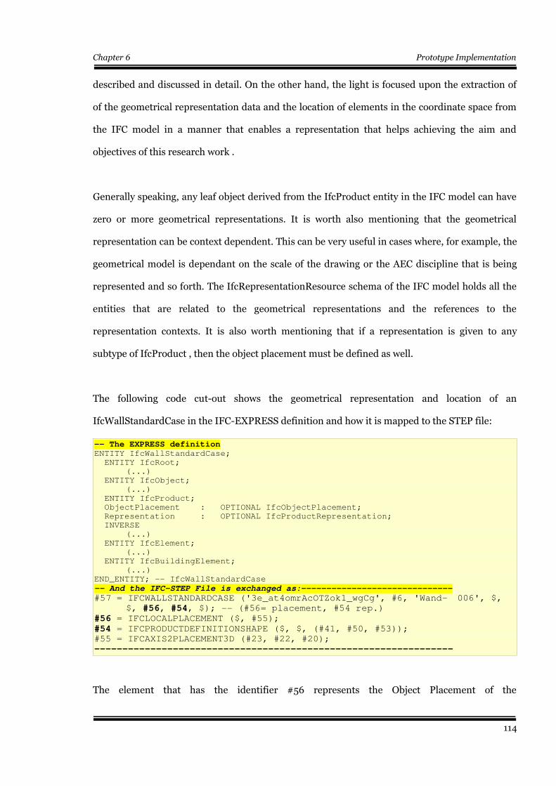
Chapter 6 Prototype Implementation
described and discussed in detail. On the other hand, the light is focused upon the extraction of
of the geometrical representation data and the location of elements in the coordinate space from
the IFC model in a manner that enables a representation that helps achieving the aim and
objectives of this research work .
Generally speaking, any leaf object derived from the IfcProduct entity in the IFC model can have
zero or more geometrical representations. It is worth also mentioning that the geometrical
representation can be context dependent. This can be very useful in cases where, for example, the
geometrical model is dependant on the scale of the drawing or the AEC discipline that is being
represented and so forth. The IfcRepresentationResource schema of the IFC model holds all the
entities that are related to the geometrical representations and the references to the
representation contexts. It is also worth mentioning that if a representation is given to any
subtype of IfcProduct , then the object placement must be defined as well.
The following code cut-out shows the geometrical representation and location of an
IfcWallStandardCase in the IFC-EXPRESS definition and how it is mapped to the STEP file:
-- The EXPRESS definitionENTITY IfcWallStandardCase;
ENTITY IfcRoot;
(...)
ENTITY IfcObject;
(...)
ENTITY IfcProduct;
ObjectPlacement : OPTIONAL IfcObjectPlacement;
Representation : OPTIONAL IfcProductRepresentation;
INVERSE
(...)
ENTITY IfcElement;
(...)
ENTITY IfcBuildingElement;
(...)
END_ENTITY; -- IfcWallStandardCase
-- And the IFC-STEP File is exchanged as:------------------------------
#57 = IFCWALLSTANDARDCASE ('3e_at4omrAcOTZok1_wgCg', #6, 'Wand- 006', $,
$, #56, #54, $); -- (#56= placement, #54 rep.) #56 = IFCLOCALPLACEMENT ($, #55);#54 = IFCPRODUCTDEFINITIONSHAPE ($, $, (#41, #50, #53));#55 = IFCAXIS2PLACEMENT3D (#23, #22, #20);
----------------------------------------------------------------
The element that has the identifier #56 represents the Object Placement of the
114
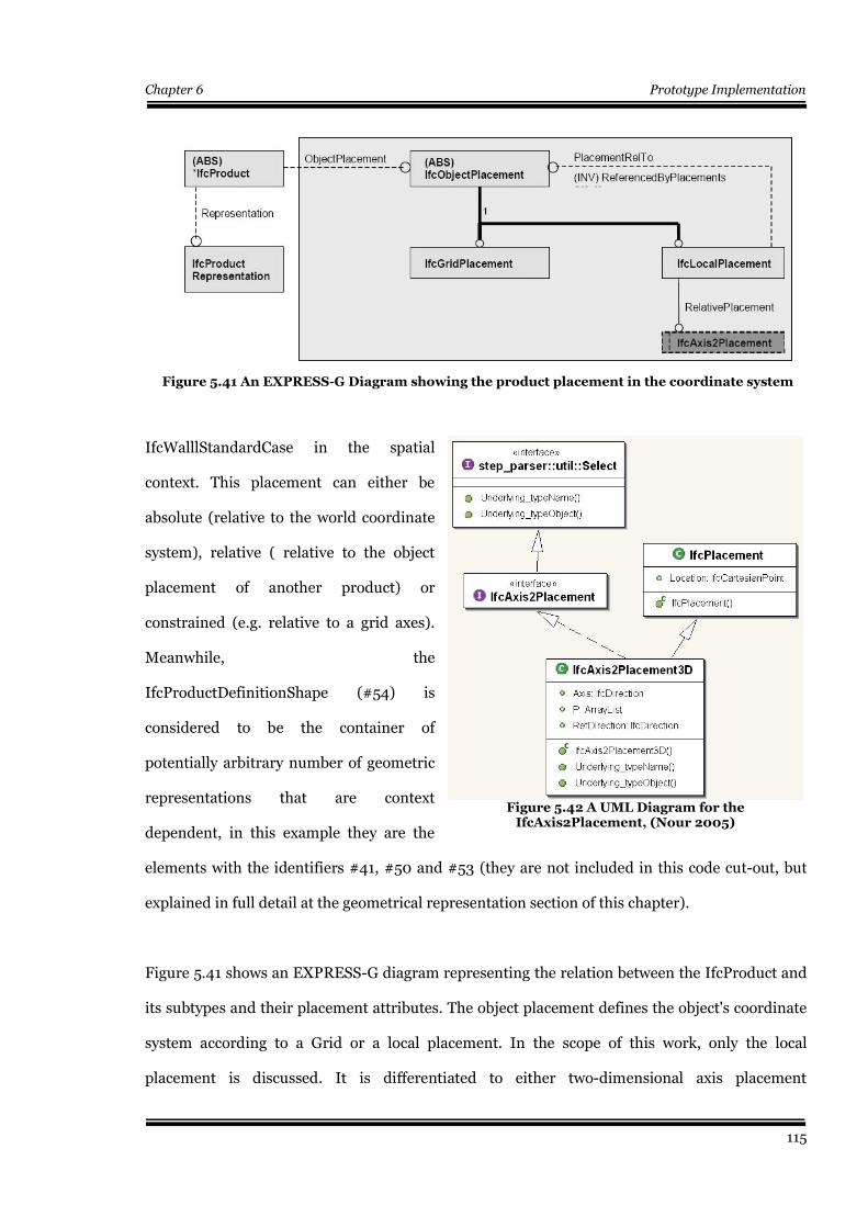
Chapter 6 Prototype Implementation
IfcWalllStandardCase in the spatial
context. This placement can either be
absolute (relative to the world coordinate
system), relative ( relative to the object
placement of another product) or
constrained (e.g. relative to a grid axes).
Meanwhile, the
IfcProductDefinitionShape (#54) is
considered to be the container of
potentially arbitrary number of geometric
representations that are context
dependent, in this example they are the
elements with the identifiers #41, #50 and #53 (they are not included in this code cut-out, but
explained in full detail at the geometrical representation section of this chapter).
Figure 5.41 shows an EXPRESS-G diagram representing the relation between the IfcProduct and
its subtypes and their placement attributes. The object placement defines the object's coordinate
system according to a Grid or a local placement. In the scope of this work, only the local
placement is discussed. It is differentiated to either two-dimensional axis placement
115
Figure 5.41 An EXPRESS-G Diagram showing the product placement in the coordinate system
Figure 5.42 A UML Diagram for theIfcAxis2Placement, (Nour 2005)
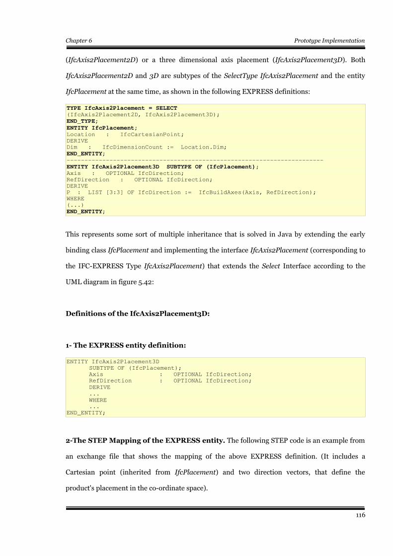
Chapter 6 Prototype Implementation
(IfcAxis2Placement2D) or a three dimensional axis placement (IfcAxis2Placement3D). Both
IfcAxis2Placement2D and 3D are subtypes of the SelectType IfcAxis2Placement and the entity
IfcPlacement at the same time, as shown in the following EXPRESS definitions:
TYPE IfcAxis2Placement = SELECT (IfcAxis2Placement2D, IfcAxis2Placement3D);
END_TYPE;
ENTITY IfcPlacement; Location : IfcCartesianPoint;
DERIVE
Dim : IfcDimensionCount := Location.Dim;
END_ENTITY; ------------------------------------------------------------------------
ENTITY IfcAxis2Placement3D SUBTYPE OF (IfcPlacement);Axis : OPTIONAL IfcDirection;
RefDirection : OPTIONAL IfcDirection;
DERIVE
P : LIST [3:3] OF IfcDirection := IfcBuildAxes(Axis, RefDirection);
WHERE
(...)
END_ENTITY;
This represents some sort of multiple inheritance that is solved in Java by extending the early
binding class IfcPlacement and implementing the interface IfcAxis2Placement (corresponding to
the IFC-EXPRESS Type IfcAxis2Placement) that extends the Select Interface according to the
UML diagram in figure 5.42:
Definitions of the IfcAxis2Placement3D:
1- The EXPRESS entity definition:
ENTITY IfcAxis2Placement3D
SUBTYPE OF (IfcPlacement);
Axis : OPTIONAL IfcDirection;
RefDirection : OPTIONAL IfcDirection;
DERIVE ...
WHERE
...
END_ENTITY;
2-The STEP Mapping of the EXPRESS entity. The following STEP code is an example from
an exchange file that shows the mapping of the above EXPRESS definition. (It includes a
Cartesian point (inherited from IfcPlacement) and two direction vectors, that define the
product's placement in the co-ordinate space).
116
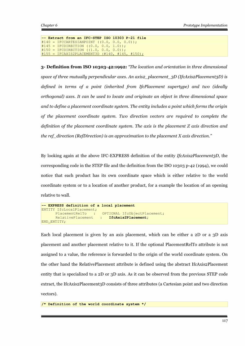
Chapter 6 Prototype Implementation
-- Extract from an IFC-STEP ISO 10303 P-21 file#140 = IFCCARTESIANPOINT ((0.0, 0.0, 0.0));
#145 = IFCDIRECTION ((0.0, 0.0, 1.0));
#150 = IFCDIRECTION ((1.0, 0.0, 0.0));
#155 = IFCAXIS2PLACEMENT3D (#140, #145, #150);
3- Definition from ISO 10303-42:1992: “The location and orientation in three dimensional
space of three mutually perpendicular axes. An axis2_placement_3D (IfcAxis2Placement3D) is
defined in terms of a point (inherited from IfcPlacement supertype) and two (ideally
orthogonal) axes. It can be used to locate and originate an object in three dimensional space
and to define a placement coordinate system. The entity includes a point which forms the origin
of the placement coordinate system. Two direction vectors are required to complete the
definition of the placement coordinate system. The axis is the placement Z axis direction and
the ref_direction (RefDirection) is an approximation to the placement X axis direction.”
By looking again at the above IFC-EXPRESS definition of the entity IfcAxis2Placement3D, the
corresponding code in the STEP file and the definition from the ISO 10303 p-42 (1994), we could
notice that each product has its own coordinate space which is either relative to the world
coordinate system or to a location of another product, for a example the location of an opening
relative to wall.
-- EXPRESS definition of a local placementENTITY IfcLocalPlacement;
PlacementRelTo : OPTIONAL IfcObjectPlacement;
RelativePlacement : IfcAxis2Placement; END_ENTITY;
Each local placement is given by an axis placement, which can be either a 2D or a 3D axis
placement and another placement relative to it. If the optional PlacementRelTo attribute is not
assigned to a value, the reference is forwarded to the origin of the world coordinate system. On
the other hand the RelativePlacement attribute is defined using the abstract IfcAxis2Placement
entity that is specialized to a 2D or 3D axis. As it can be observed from the previous STEP code
extract, the IfcAxis2Placement3D consists of three attributes (a Cartesian point and two direction
vectors).
/* Definition of the world coordinate system */
117
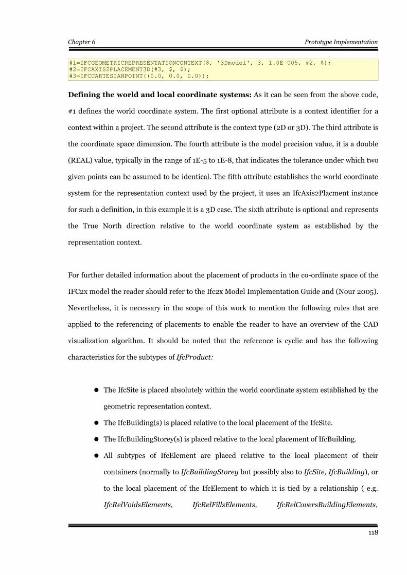
Chapter 6 Prototype Implementation
#1=IFCGEOMETRICREPRESENTATIONCONTEXT($, '3Dmodel', 3, 1.0E-005, #2, $);
#2=IFCAXIS2PLACEMENT3D(#3, $, $);
#3=IFCCARTESIANPOINT((0.0, 0.0, 0.0));
Defining the world and local coordinate systems: As it can be seen from the above code,
#1 defines the world coordinate system. The first optional attribute is a context identifier for a
context within a project. The second attribute is the context type (2D or 3D). The third attribute is
the coordinate space dimension. The fourth attribute is the model precision value, it is a double
(REAL) value, typically in the range of 1E-5 to 1E-8, that indicates the tolerance under which two
given points can be assumed to be identical. The fifth attribute establishes the world coordinate
system for the representation context used by the project, it uses an IfcAxis2Placment instance
for such a definition, in this example it is a 3D case. The sixth attribute is optional and represents
the True North direction relative to the world coordinate system as established by the
representation context.
For further detailed information about the placement of products in the co-ordinate space of the
IFC2x model the reader should refer to the Ifc2x Model Implementation Guide and (Nour 2005).
Nevertheless, it is necessary in the scope of this work to mention the following rules that are
applied to the referencing of placements to enable the reader to have an overview of the CAD
visualization algorithm. It should be noted that the reference is cyclic and has the following
characteristics for the subtypes of IfcProduct:
● The IfcSite is placed absolutely within the world coordinate system established by the
geometric representation context.
● The IfcBuilding(s) is placed relative to the local placement of the IfcSite.
● The IfcBuildingStorey(s) is placed relative to the local placement of IfcBuilding.
● All subtypes of IfcElement are placed relative to the local placement of their
containers (normally to IfcBuildingStorey but possibly also to IfcSite, IfcBuilding), or
to the local placement of the IfcElement to which it is tied by a relationship ( e.g.
IfcRelVoidsElements, IfcRelFillsElements, IfcRelCoversBuildingElements,
118
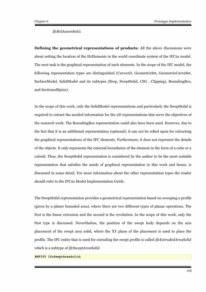
Chapter 6 Prototype Implementation
IfcRelAssembels).
Defining the geometrical representations of products: All the above discussions were
about setting the location of the IfcElements in the world coordinate system of the IFC2x model.
The next task is the graphical representation of such elements. In the scope of the IFC model, the
following representation types are distinguished (Curve2D, GeometricSet, GeometricCurveSet,
SurfaceModel, SolidModel and its subtypes (Brep, SweptSolid, CSG , Clipping), BoundingBox,
and SectionedSpine).
In the scope of this work, only the SolidModel representations and particularly the SweptSolid is
required to extract the needed information for the 2D representations that serve the objectives of
the research work. The BoundingBox representation could also have been used. However, due to
the fact that it is an additional representation (optional), it can not be relied upon for extracting
the graphical representations of the IFC elements. Furthermore, it does not represent the details
of the objects. It only represents the external boundaries of the element in the form of a cube or a
cuboid. Thus, the SweptSolid representation is considered by the author to be the most suitable
representation that satisfies the needs of graphical representation in this work and hence, is
discussed in some detail. For more information about the other representation types the reader
should refer to the IFC2x Model Implementation Guide.
The SweptSolid representation provides a geometrical representation based on sweeping a profile
(given by a planer bounded area), where there are two different types of planar operations. The
first is the linear extrusion and the second is the revolution. In the scope of this work, only the
first type is discussed. Nevertheless, the position of the swept body depends on the axis
placement of the swept area solid, where the XY plane of the placement is used to place the
profile. The IFC entity that is used for extruding the swept profile is called IfcExtrudedAreaSolid
which is a subtype of IfcSweptAreaSolid.
ENTITY IfcSweptAreaSolid;
119
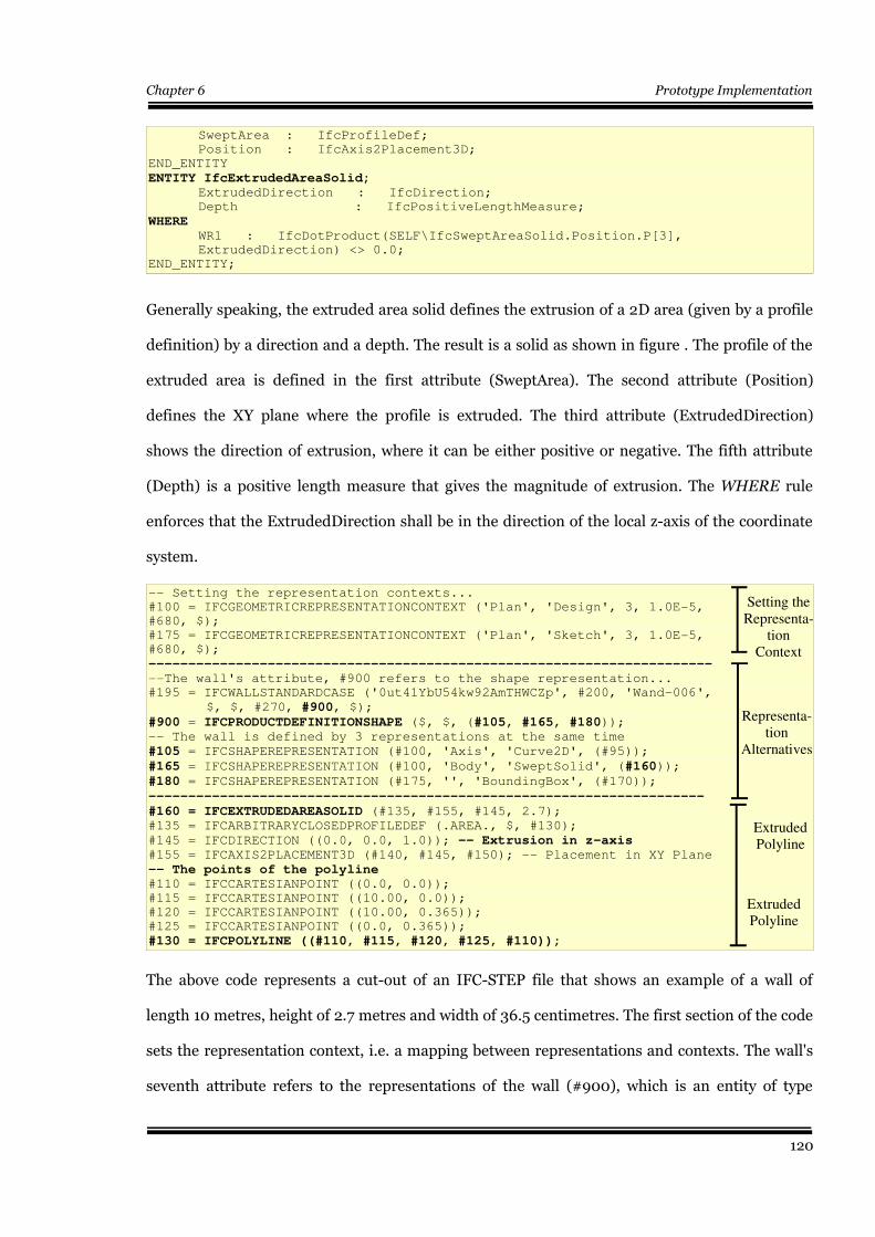
Chapter 6 Prototype Implementation
SweptArea : IfcProfileDef;
Position : IfcAxis2Placement3D;
END_ENTITY
ENTITY IfcExtrudedAreaSolid; ExtrudedDirection : IfcDirection;
Depth : IfcPositiveLengthMeasure;
WHERE WR1 : IfcDotProduct(SELF\IfcSweptAreaSolid.Position.P[3],
ExtrudedDirection) <> 0.0;
END_ENTITY;
Generally speaking, the extruded area solid defines the extrusion of a 2D area (given by a profile
definition) by a direction and a depth. The result is a solid as shown in figure . The profile of the
extruded area is defined in the first attribute (SweptArea). The second attribute (Position)
defines the XY plane where the profile is extruded. The third attribute (ExtrudedDirection)
shows the direction of extrusion, where it can be either positive or negative. The fifth attribute
(Depth) is a positive length measure that gives the magnitude of extrusion. The WHERE rule
enforces that the ExtrudedDirection shall be in the direction of the local z-axis of the coordinate
system.
-- Setting the representation contexts...
#100 = IFCGEOMETRICREPRESENTATIONCONTEXT ('Plan', 'Design', 3, 1.0E-5,
#680, $);
#175 = IFCGEOMETRICREPRESENTATIONCONTEXT ('Plan', 'Sketch', 3, 1.0E-5,
#680, $);
----------------------------------------------------------------------- --The wall's attribute, #900 refers to the shape representation...
#195 = IFCWALLSTANDARDCASE ('0ut41YbU54kw92AmTHWCZp', #200, 'Wand-006',
$, $, #270, #900, $);
#900 = IFCPRODUCTDEFINITIONSHAPE ($, $, (#105, #165, #180));-- The wall is defined by 3 representations at the same time
#105 = IFCSHAPEREPRESENTATION (#100, 'Axis', 'Curve2D', (#95));
#165 = IFCSHAPEREPRESENTATION (#100, 'Body', 'SweptSolid', (#160));
#180 = IFCSHAPEREPRESENTATION (#175, '', 'BoundingBox', (#170));
----------------------------------------------------------------------
#160 = IFCEXTRUDEDAREASOLID (#135, #155, #145, 2.7);#135 = IFCARBITRARYCLOSEDPROFILEDEF (.AREA., $, #130);
#145 = IFCDIRECTION ((0.0, 0.0, 1.0)); -- Extrusion in z-axis#155 = IFCAXIS2PLACEMENT3D (#140, #145, #150); -- Placement in XY Plane
-- The points of the polyline #110 = IFCCARTESIANPOINT ((0.0, 0.0));
#115 = IFCCARTESIANPOINT ((10.00, 0.0));
#120 = IFCCARTESIANPOINT ((10.00, 0.365));
#125 = IFCCARTESIANPOINT ((0.0, 0.365));
#130 = IFCPOLYLINE ((#110, #115, #120, #125, #110));
The above code represents a cut-out of an IFC-STEP file that shows an example of a wall of
length 10 metres, height of 2.7 metres and width of 36.5 centimetres. The first section of the code
sets the representation context, i.e. a mapping between representations and contexts. The wall's
seventh attribute refers to the representations of the wall (#900), which is an entity of type
120
Setting the Representa-
tion Context
Representa-tion
Alternatives
Extruded Polyline
Extruded Polyline
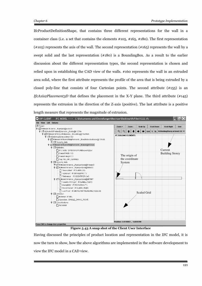
Chapter 6 Prototype Implementation
IfcProductDefinitionShape, that contains three different representations for the wall in a
container class (i.e. a set that contains the elements #105, #165, #180). The first representation
(#105) represents the axis of the wall. The second representation (#165) represents the wall by a
swept solid and the last representation (#180) is a BoundingBox. As a result to the earlier
discussion about the different representation types, the second representation is chosen and
relied upon in establishing the CAD view of the walls. #160 represents the wall in an extruded
area solid, where the first attribute represents the profile of the area that is being extruded by a
closed poly-line that consists of four Cartesian points. The second attribute (#155) is an
IfcAxis2Placement3D that defines the placement in the X-Y plane. The third attribute (#145)
represents the extrusion in the direction of the Z-axis (positive). The last attribute is a positive
length measure that represents the magnitude of extrusion.
Having discussed the principles of product location and representation in the IFC model, it is
now the turn to show, how the above algorithms are implemented in the software development to
view the IFC model in a CAD view.
121
Figure 5.43 A snap shot of the Client User Interface
Current Building Storey
The origin of the coordinate System
Scaled Grid
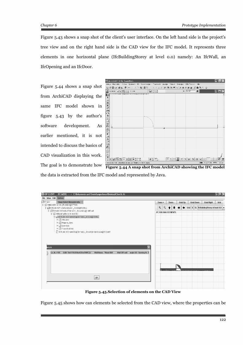
Chapter 6 Prototype Implementation
Figure 5.43 shows a snap shot of the client's user interface. On the left hand side is the project's
tree view and on the right hand side is the CAD view for the IFC model. It represents three
elements in one horizontal plane (IfcBuildingStorey at level 0.0) namely: An IfcWall, an
IfcOpening and an IfcDoor.
Figure 5.44 shows a snap shot
from ArchiCAD displaying the
same IFC model shown in
figure 5.43 by the author's
software development. As
earlier mentioned, it is not
intended to discuss the basics of
CAD visualization in this work.
The goal is to demonstrate how
the data is extracted from the IFC model and represented by Java.
Figure 5.45 shows how can elements be selected from the CAD view, where the properties can be
122
Figure 5.45.Selection of elements on the CAD View
Figure 5.44 A snap shot from ArchiCAD showing the IFC model
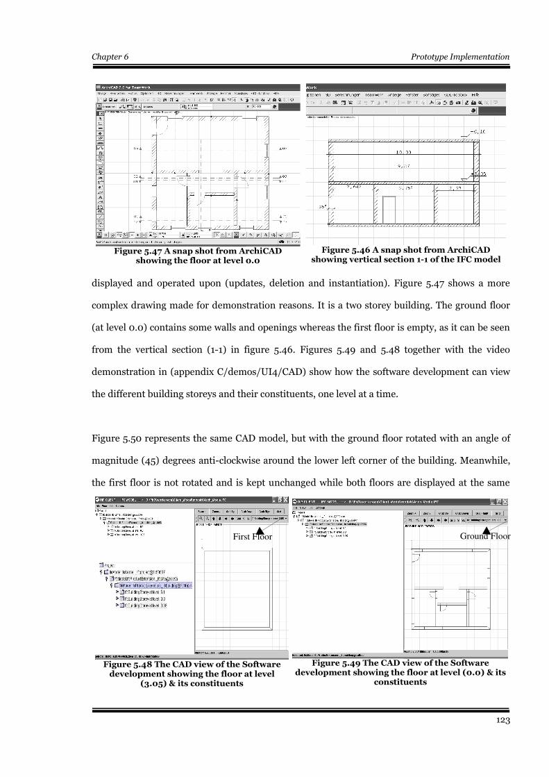
Chapter 6 Prototype Implementation
displayed and operated upon (updates, deletion and instantiation). Figure 5.47 shows a more
complex drawing made for demonstration reasons. It is a two storey building. The ground floor
(at level 0.0) contains some walls and openings whereas the first floor is empty, as it can be seen
from the vertical section (1-1) in figure 5.46. Figures 5.49 and 5.48 together with the video
demonstration in (appendix C/demos/UI4/CAD) show how the software development can view
the different building storeys and their constituents, one level at a time.
Figure 5.50 represents the same CAD model, but with the ground floor rotated with an angle of
magnitude (45) degrees anti-clockwise around the lower left corner of the building. Meanwhile,
the first floor is not rotated and is kept unchanged while both floors are displayed at the same
123
Figure 5.46 A snap shot from ArchiCADshowing vertical section 1-1 of the IFC model
Figure 5.49 The CAD view of the Softwaredevelopment showing the floor at level (0.0) & its
constituents
Figure 5.47 A snap shot from ArchiCADshowing the floor at level 0.0
Figure 5.48 The CAD view of the Softwaredevelopment showing the floor at level
(3.05) & its constituents
First Floor Ground Floor
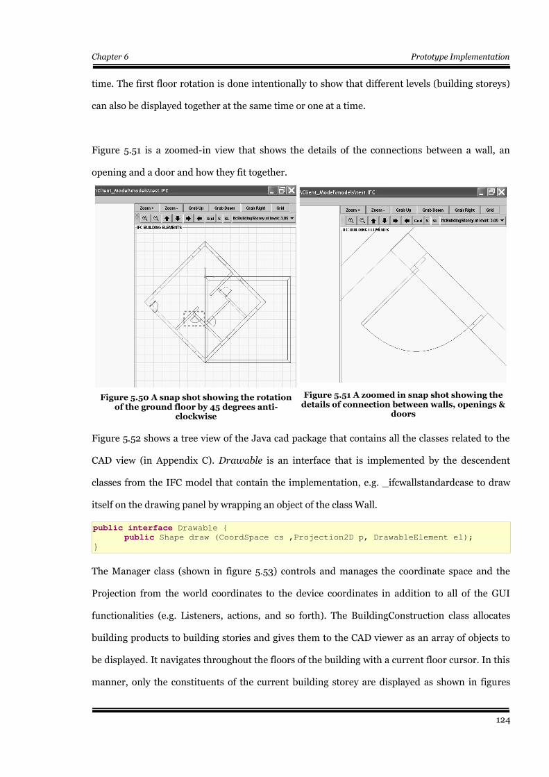
Chapter 6 Prototype Implementation
time. The first floor rotation is done intentionally to show that different levels (building storeys)
can also be displayed together at the same time or one at a time.
Figure 5.51 is a zoomed-in view that shows the details of the connections between a wall, an
opening and a door and how they fit together.
Figure 5.52 shows a tree view of the Java cad package that contains all the classes related to the
CAD view (in Appendix C). Drawable is an interface that is implemented by the descendent
classes from the IFC model that contain the implementation, e.g. _ifcwallstandardcase to draw
itself on the drawing panel by wrapping an object of the class Wall.
public interface Drawable {
public Shape draw (CoordSpace cs ,Projection2D p, DrawableElement el);
}
The Manager class (shown in figure 5.53) controls and manages the coordinate space and the
Projection from the world coordinates to the device coordinates in addition to all of the GUI
functionalities (e.g. Listeners, actions, and so forth). The BuildingConstruction class allocates
building products to building stories and gives them to the CAD viewer as an array of objects to
be displayed. It navigates throughout the floors of the building with a current floor cursor. In this
manner, only the constituents of the current building storey are displayed as shown in figures
124
Figure 5.51 A zoomed in snap shot showing thedetails of connection between walls, openings &
doors
Figure 5.50 A snap shot showing the rotationof the ground floor by 45 degrees anti-
clockwise
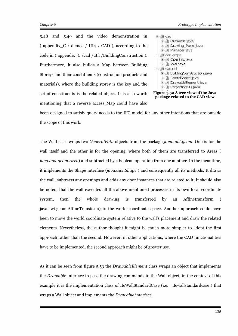
Chapter 6 Prototype Implementation
5.48 and 5.49 and the video demonstration in
( appendix_C / demos / UI4 / CAD ), according to the
code in ( appendix_C /cad /util /BuildingConstruction ).
Furthermore, it also builds a Map between Building
Storeys and their constituents (construction products and
materials), where the building storey is the key and the
set of constituents is the related object. It is also worth
mentioning that a reverse access Map could have also
been designed to satisfy query needs to the IFC model for any other intentions that are outside
the scope of this work.
The Wall class wraps two GeneralPath objects from the package java.awt.geom. One is for the
wall itself and the other is for the opening, where both of them are transferred to Areas (
java.awt.geom.Area) and subtracted by a boolean operation from one another. In the meantime,
it implements the Shape interface (java.awt.Shape ) and consequently all its methods. It draws
the wall, subtracts any openings and adds any door instances that are related to it. It should also
be noted, that the wall executes all the above mentioned processes in its own local coordinate
system, then the whole drawing is transferred by an Affinetransform (
java.awt.geom.AffineTransform) to the world coordinate space. Another approach could have
been to move the world coordinate system relative to the wall's placement and draw the related
elements. Nevertheless, the author thought it might be much more simpler to adopt the first
approach rather than the second. However, in other applications, where the CAD functionalities
have to be implemented, the second approach might be of greater use.
As it can be seen from figure 5.53 the DrawableElement class wraps an object that implements
the Drawable interface to pass the drawing commands to the Wall object, in the context of this
example it is the implementation class of IfcWallStandardCase (i.e. _ifcwallstandardcase ) that
wraps a Wall object and implements the Drawable interface.
125
Figure 5.52 A tree view of the Javapackage related to the CAD view
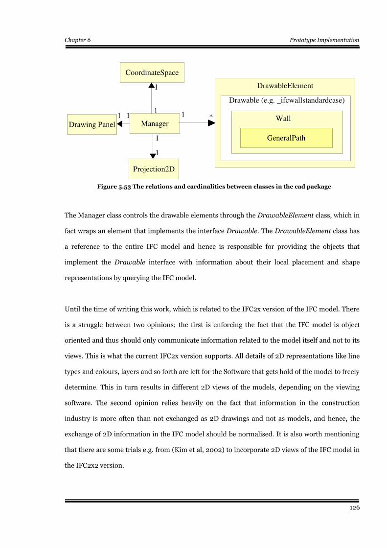
Chapter 6 Prototype Implementation
The Manager class controls the drawable elements through the DrawableElement class, which in
fact wraps an element that implements the interface Drawable. The DrawableElement class has
a reference to the entire IFC model and hence is responsible for providing the objects that
implement the Drawable interface with information about their local placement and shape
representations by querying the IFC model.
Until the time of writing this work, which is related to the IFC2x version of the IFC model. There
is a struggle between two opinions; the first is enforcing the fact that the IFC model is object
oriented and thus should only communicate information related to the model itself and not to its
views. This is what the current IFC2x version supports. All details of 2D representations like line
types and colours, layers and so forth are left for the Software that gets hold of the model to freely
determine. This in turn results in different 2D views of the models, depending on the viewing
software. The second opinion relies heavily on the fact that information in the construction
industry is more often than not exchanged as 2D drawings and not as models, and hence, the
exchange of 2D information in the IFC model should be normalised. It is also worth mentioning
that there are some trials e.g. from (Kim et al, 2002) to incorporate 2D views of the IFC model in
the IFC2x2 version.
126
Figure 5.53 The relations and cardinalities between classes in the cad package
GeneralPath
Drawable (e.g. _ifcwallstandardcase)
WallManager
1 *1
1
CoordinateSpace
Projection2D
1
1
Drawing Panel11
DrawableElement
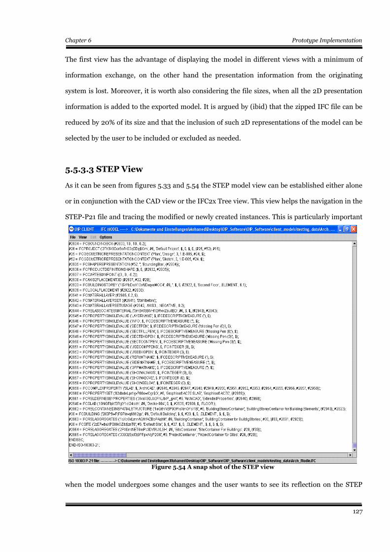
Chapter 6 Prototype Implementation
The first view has the advantage of displaying the model in different views with a minimum of
information exchange, on the other hand the presentation information from the originating
system is lost. Moreover, it is worth also considering the file sizes, when all the 2D presentation
information is added to the exported model. It is argued by (ibid) that the zipped IFC file can be
reduced by 20% of its size and that the inclusion of such 2D representations of the model can be
selected by the user to be included or excluded as needed.
5.5.3.3 STEP View
As it can be seen from figures 5.33 and 5.54 the STEP model view can be established either alone
or in conjunction with the CAD view or the IFC2x Tree view. This view helps the navigation in the
STEP-P21 file and tracing the modified or newly created instances. This is particularly important
when the model undergoes some changes and the user wants to see its reflection on the STEP
127
Figure 5.54 A snap shot of the STEP view

Chapter 6 Prototype Implementation
model. It should be noted that the modifications can only be viewed after exporting the model,
where the STEPWriter14 is called to create the STEP view of the building information model.
5.5.4 Operations on the IFC Model
An important aim of this work is to enable carrying out operations needed to modify and keep the
IFC model up-to-date. Among these operations are the instantiation of new property sets,
property definitions, materials and classifications. Moreover, the developed software should
should be able to carry out changes to the model like changing the values of the the above
mentioned elements or even deleting them. This is envisaged to respond to the changes that a
construction project undergoes in the design, specification and value engineering stages.
Furthermore, this is considered to be the means by which the the construction product's life cycle
properties could be mapped to the IFC model all over the the life cycle of the building project
itself. An important goal in this process is not to cram the IFC model with all available life cycle
information for each product in the project. However, the aim is to supply and support the model
with up-to-date information from a continually updated and extensible data source. This implies
that only needed information is mapped and instantiated in the model and that updates should
always be reachable and mergable. In this way, the size of the IFC model and its exchange format
(STEP ISO 10303-P21) can be minimized i.e. a fat free communication model can be reached. In
other words, the model should exist in parallel to its life cycle information side by side and should
be able to reference and import any piece of information according to the user 's(client's) needs.
14 It is described in detail in section 5.5.4.4 and the code is found in appendix_C/step_writer/*
128
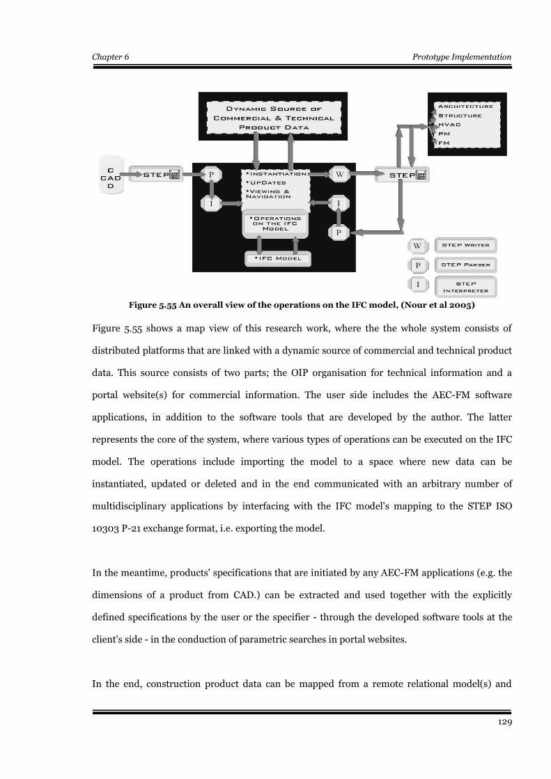
Chapter 6 Prototype Implementation
Figure 5.55 shows a map view of this research work, where the the whole system consists of
distributed platforms that are linked with a dynamic source of commercial and technical product
data. This source consists of two parts; the OIP organisation for technical information and a
portal website(s) for commercial information. The user side includes the AEC-FM software
applications, in addition to the software tools that are developed by the author. The latter
represents the core of the system, where various types of operations can be executed on the IFC
model. The operations include importing the model to a space where new data can be
instantiated, updated or deleted and in the end communicated with an arbitrary number of
multidisciplinary applications by interfacing with the IFC model's mapping to the STEP ISO
10303 P-21 exchange format, i.e. exporting the model.
In the meantime, products' specifications that are initiated by any AEC-FM applications (e.g. the
dimensions of a product from CAD.) can be extracted and used together with the explicitly
defined specifications by the user or the specifier - through the developed software tools at the
client's side - in the conduction of parametric searches in portal websites.
In the end, construction product data can be mapped from a remote relational model(s) and
129
Figure 5.55 An overall view of the operations on the IFC model, (Nour et al 2005)

Chapter 6 Prototype Implementation
merged into the IFC object oriented model -at the client's side- all over the whole life cycle of the
product, whenever a need for product data or updates arises. This is done by using the OIP
unique identification to reach the product's data (information packs). The latter enables both the
reach and richness of information about construction products and keeps the IFC building
information model up-to-date, in addition to extending the limits of its information content
beyond its borders.
5.5.4.1 Instantiation
In general and as shown in figure 5.5615,
before carrying out any instantiation
process to a property set, property
definition, a classification or even a new
product, the IFC model has to be searched
to find the element to which the new
instance is related (IfcBuildingElement). In
the scope of this work, this is done by
selecting a product from either the project's
tree view or the project's CAD view. Once a product is selected, then the IFC model is queried to
find the objectified relationship classes instances (IfcRelxxx) that link it with other parts of the
model – like a cross reference table in a relational database – and consequently, an arbitrary
number of new properties, classifications, constituents or materials can be added to the product.
The following is a sample example that demonstrates the instantiation process of a property set.
The instantiation of classifications, materials, materials' properties and classifications follow the
same algorithm.
As a first step for the instantiation of new property sets in the IFC Model, new Java classes have
15 Figure 5.56 is an EXPRESS-G diagram that represents an abstraction by the author that ignores inheritance of theEXPRESS entities and some of the attributes. This is done for clarification reasons and to make the diagram as simple aspossible.
130
Figure 5.56 An EXPRESS-G diagram showing therelation between properties & construction
products through the definition relationship,(Nour er al 2005)
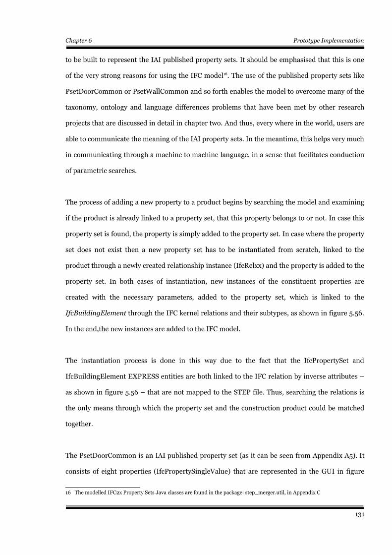
Chapter 6 Prototype Implementation
to be built to represent the IAI published property sets. It should be emphasised that this is one
of the very strong reasons for using the IFC model16. The use of the published property sets like
PsetDoorCommon or PsetWallCommon and so forth enables the model to overcome many of the
taxonomy, ontology and language differences problems that have been met by other research
projects that are discussed in detail in chapter two. And thus, every where in the world, users are
able to communicate the meaning of the IAI property sets. In the meantime, this helps very much
in communicating through a machine to machine language, in a sense that facilitates conduction
of parametric searches.
The process of adding a new property to a product begins by searching the model and examining
if the product is already linked to a property set, that this property belongs to or not. In case this
property set is found, the property is simply added to the property set. In case where the property
set does not exist then a new property set has to be instantiated from scratch, linked to the
product through a newly created relationship instance (IfcRelxx) and the property is added to the
property set. In both cases of instantiation, new instances of the constituent properties are
created with the necessary parameters, added to the property set, which is linked to the
IfcBuildingElement through the IFC kernel relations and their subtypes, as shown in figure 5.56.
In the end,the new instances are added to the IFC model.
The instantiation process is done in this way due to the fact that the IfcPropertySet and
IfcBuildingElement EXPRESS entities are both linked to the IFC relation by inverse attributes –
as shown in figure 5.56 – that are not mapped to the STEP file. Thus, searching the relations is
the only means through which the property set and the construction product could be matched
together.
The PsetDoorCommon is an IAI published property set (as it can be seen from Appendix A5). It
consists of eight properties (IfcPropertySingleValue) that are represented in the GUI in figure
16 The modelled IFC2x Property Sets Java classes are found in the package: step_merger.util, in Appendix C
131
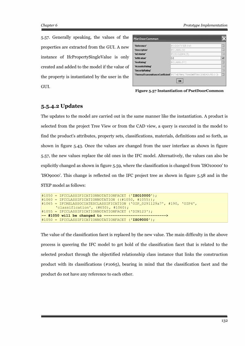
Chapter 6 Prototype Implementation
5.57. Generally speaking, the values of the
properties are extracted from the GUI. A new
instance of IfcPropertySingleValue is only
created and added to the model if the value of
the property is instantiated by the user in the
GUI.
5.5.4.2 Updates
The updates to the model are carried out in the same manner like the instantiation. A product is
selected from the project Tree View or from the CAD view, a query is executed in the model to
find the product's attributes, property sets, classifications, materials, definitions and so forth, as
shown in figure 5.43. Once the values are changed from the user interface as shown in figure
5.57, the new values replace the old ones in the IFC model. Alternatively, the values can also be
explicitly changed as shown in figure 5.59, where the classification is changed from 'ISO10000' to
'ISO9000'. This change is reflected on the IFC project tree as shown in figure 5.58 and in the
STEP model as follows:
#1050 = IFCCLASSIFICATIONNOTATIONFACET ('ISO10000');#1060 = IFCCLASSIFICATIONNOTATION ((#1050, #1055));
#1065 = IFCRELASSOCIATESCLASSIFICATION ('OIP_0291129a7', #190, 'OIP4',
'classification', (#650), #1060);
#1055 = IFCCLASSIFICATIONNOTATIONFACET ('DIN123');
-- #1050 will be changed to ---------------------------->
#1050 = IFCCLASSIFICATIONNOTATIONFACET ('ISO9000');
The value of the classification facet is replaced by the new value. The main difficulty in the above
process is queering the IFC model to get hold of the classification facet that is related to the
selected product through the objectified relationship class instance that links the construction
product with its classifications (#1065), bearing in mind that the classification facet and the
product do not have any reference to each other.
132
Figure 5.57 Instantiation of PsetDoorCommon
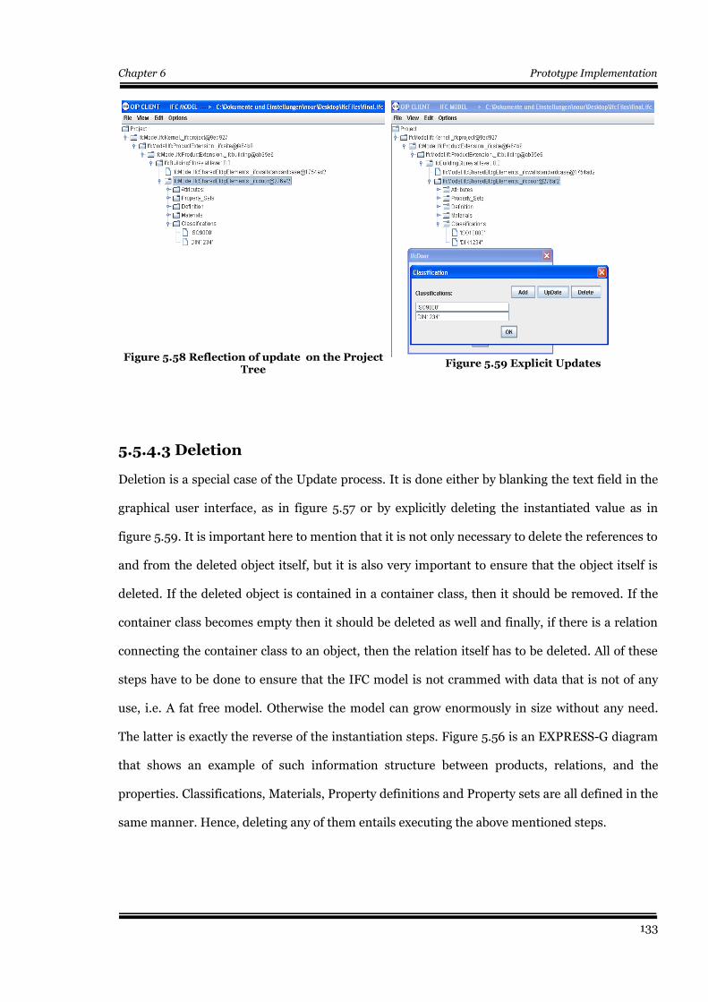
Chapter 6 Prototype Implementation
5.5.4.3 Deletion
Deletion is a special case of the Update process. It is done either by blanking the text field in the
graphical user interface, as in figure 5.57 or by explicitly deleting the instantiated value as in
figure 5.59. It is important here to mention that it is not only necessary to delete the references to
and from the deleted object itself, but it is also very important to ensure that the object itself is
deleted. If the deleted object is contained in a container class, then it should be removed. If the
container class becomes empty then it should be deleted as well and finally, if there is a relation
connecting the container class to an object, then the relation itself has to be deleted. All of these
steps have to be done to ensure that the IFC model is not crammed with data that is not of any
use, i.e. A fat free model. Otherwise the model can grow enormously in size without any need.
The latter is exactly the reverse of the instantiation steps. Figure 5.56 is an EXPRESS-G diagram
that shows an example of such information structure between products, relations, and the
properties. Classifications, Materials, Property definitions and Property sets are all defined in the
same manner. Hence, deleting any of them entails executing the above mentioned steps.
133
Figure 5.58 Reflection of update on the ProjectTree
Figure 5.59 Explicit Updates
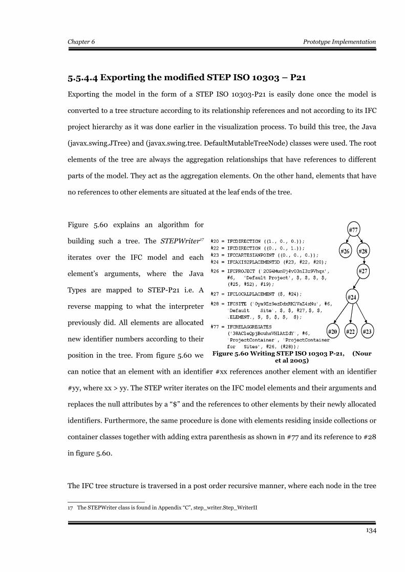
Chapter 6 Prototype Implementation
5.5.4.4 Exporting the modified STEP ISO 10303 – P21
Exporting the model in the form of a STEP ISO 10303-P21 is easily done once the model is
converted to a tree structure according to its relationship references and not according to its IFC
project hierarchy as it was done earlier in the visualization process. To build this tree, the Java
(javax.swing.JTree) and (javax.swing.tree. DefaultMutableTreeNode) classes were used. The root
elements of the tree are always the aggregation relationships that have references to different
parts of the model. They act as the aggregation elements. On the other hand, elements that have
no references to other elements are situated at the leaf ends of the tree.
Figure 5.60 explains an algorithm for
building such a tree. The STEPWriter17
iterates over the IFC model and each
element’s arguments, where the Java
Types are mapped to STEP-P21 i.e. A
reverse mapping to what the interpreter
previously did. All elements are allocated
new identifier numbers according to their
position in the tree. From figure 5.60 we
can notice that an element with an identifier #xx references another element with an identifier
#yy, where xx > yy. The STEP writer iterates on the IFC model elements and their arguments and
replaces the null attributes by a “$” and the references to other elements by their newly allocated
identifiers. Furthermore, the same procedure is done with elements residing inside collections or
container classes together with adding extra parenthesis as shown in #77 and its reference to #28
in figure 5.60.
The IFC tree structure is traversed in a post order recursive manner, where each node in the tree
17 The STEPWriter class is found in Appendix “C”, step_writer.Step_WriterII
134
Figure 5.60 Writing STEP ISO 10303 P-21, (Nouret al 2005)
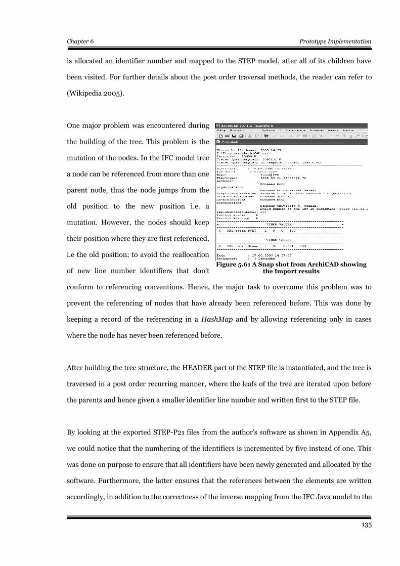
Chapter 6 Prototype Implementation
is allocated an identifier number and mapped to the STEP model, after all of its children have
been visited. For further details about the post order traversal methods, the reader can refer to
(Wikipedia 2005).
One major problem was encountered during
the building of the tree. This problem is the
mutation of the nodes. In the IFC model tree
a node can be referenced from more than one
parent node, thus the node jumps from the
old position to the new position i.e. a
mutation. However, the nodes should keep
their position where they are first referenced,
i.e the old position; to avoid the reallocation
of new line number identifiers that don't
conform to referencing conventions. Hence, the major task to overcome this problem was to
prevent the referencing of nodes that have already been referenced before. This was done by
keeping a record of the referencing in a HashMap and by allowing referencing only in cases
where the node has never been referenced before.
After building the tree structure, the HEADER part of the STEP file is instantiated, and the tree is
traversed in a post order recurring manner, where the leafs of the tree are iterated upon before
the parents and hence given a smaller identifier line number and written first to the STEP file.
By looking at the exported STEP-P21 files from the author's software as shown in Appendix A5,
we could notice that the numbering of the identifiers is incremented by five instead of one. This
was done on purpose to ensure that all identifiers have been newly generated and allocated by the
software. Furthermore, the latter ensures that the references between the elements are written
accordingly, in addition to the correctness of the inverse mapping from the IFC Java model to the
135
Figure 5.61 A Snap shot from ArchiCAD showingthe Import results
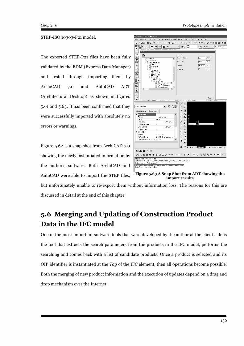
Chapter 6 Prototype Implementation
STEP-ISO 10303-P21 model.
The exported STEP-P21 files have been fully
validated by the EDM (Express Data Manager)
and tested through importing them by
ArchiCAD 7.0 and AutoCAD ADT
(Architectural Desktop) as shown in figures
5.61 and 5.63. It has been confirmed that they
were successfully imported with absolutely no
errors or warnings.
Figure 5.62 is a snap shot from ArchiCAD 7.0
showing the newly instantiated information by
the author's software. Both ArchiCAD and
AutoCAD were able to import the STEP files,
but unfortunately unable to re-export them without information loss. The reasons for this are
discussed in detail at the end of this chapter.
5.6 Merging and Updating of Construction Product
Data in the IFC model
One of the most important software tools that were developed by the author at the client side is
the tool that extracts the search parameters from the products in the IFC model, performs the
searching and comes back with a list of candidate products. Once a product is selected and its
OIP identifier is instantiated at the Tag of the IFC element, then all operations become possible.
Both the merging of new product information and the execution of updates depend on a drag and
drop mechanism over the Internet.
136
Figure 5.62 A Snap Shot from ArchiCADshowing the newly instantiated data
Figure 5.63 A Snap Shot from ADT showing theimport results
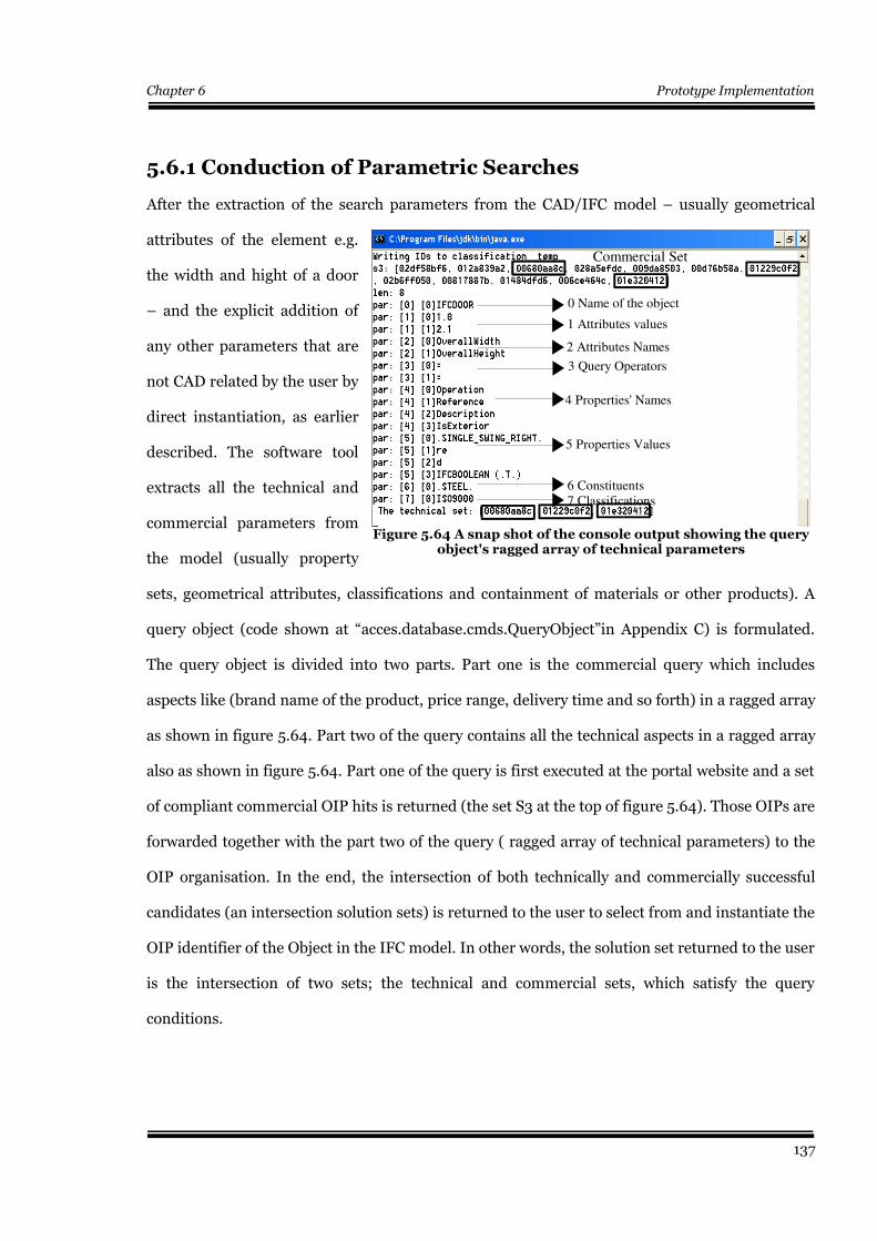
Chapter 6 Prototype Implementation
5.6.1 Conduction of Parametric Searches
After the extraction of the search parameters from the CAD/IFC model – usually geometrical
attributes of the element e.g.
the width and hight of a door
– and the explicit addition of
any other parameters that are
not CAD related by the user by
direct instantiation, as earlier
described. The software tool
extracts all the technical and
commercial parameters from
the model (usually property
sets, geometrical attributes, classifications and containment of materials or other products). A
query object (code shown at “acces.database.cmds.QueryObject”in Appendix C) is formulated.
The query object is divided into two parts. Part one is the commercial query which includes
aspects like (brand name of the product, price range, delivery time and so forth) in a ragged array
as shown in figure 5.64. Part two of the query contains all the technical aspects in a ragged array
also as shown in figure 5.64. Part one of the query is first executed at the portal website and a set
of compliant commercial OIP hits is returned (the set S3 at the top of figure 5.64). Those OIPs are
forwarded together with the part two of the query ( ragged array of technical parameters) to the
OIP organisation. In the end, the intersection of both technically and commercially successful
candidates (an intersection solution sets) is returned to the user to select from and instantiate the
OIP identifier of the Object in the IFC model. In other words, the solution set returned to the user
is the intersection of two sets; the technical and commercial sets, which satisfy the query
conditions.
137
Figure 5.64 A snap shot of the console output showing the queryobject's ragged array of technical parameters
7 Classifications6 Constituents
5 Properties Values
4 Properties' Names
3 Query Operators
2 Attributes Names
1 Attributes values
0 Name of the object
Commercial Set
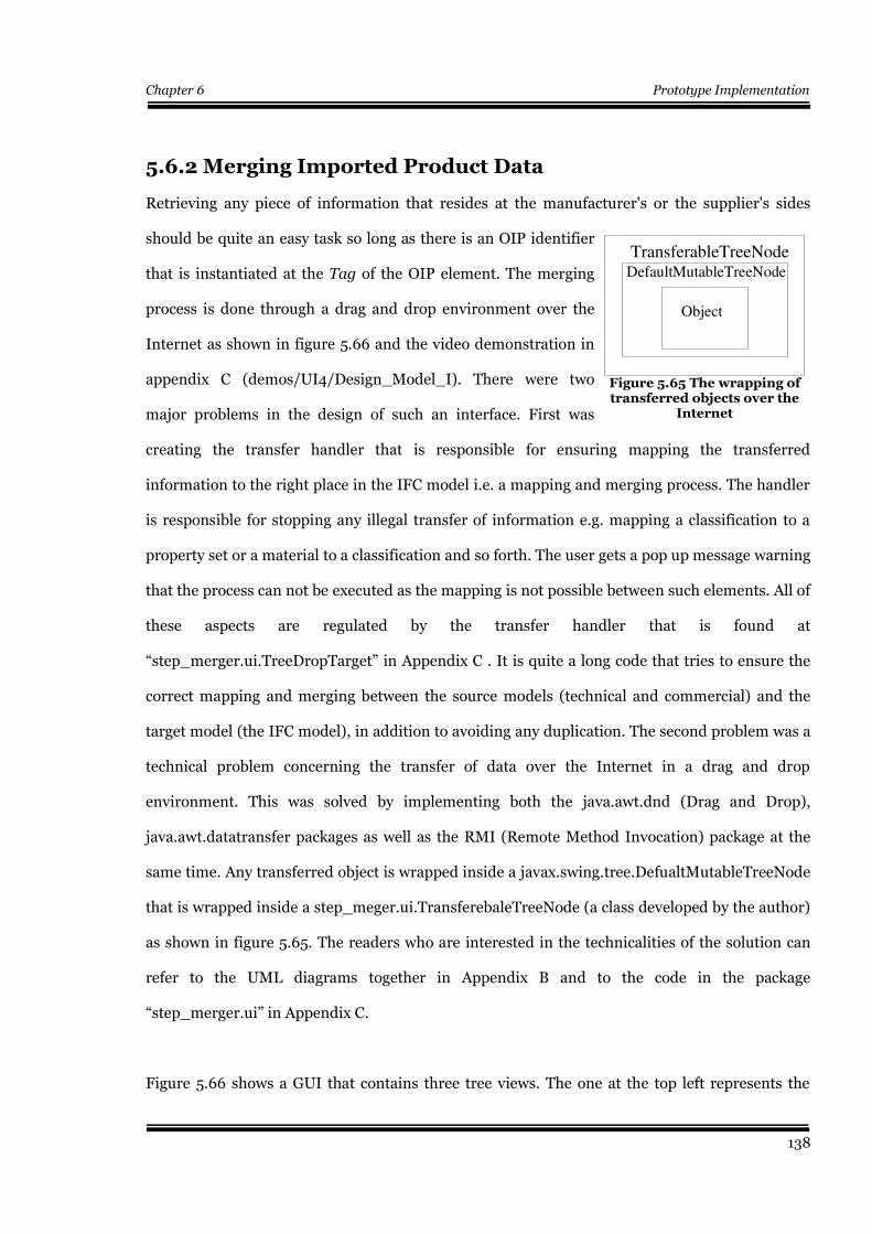
Chapter 6 Prototype Implementation
5.6.2 Merging Imported Product Data
Retrieving any piece of information that resides at the manufacturer's or the supplier's sides
should be quite an easy task so long as there is an OIP identifier
that is instantiated at the Tag of the OIP element. The merging
process is done through a drag and drop environment over the
Internet as shown in figure 5.66 and the video demonstration in
appendix C (demos/UI4/Design_Model_I). There were two
major problems in the design of such an interface. First was
creating the transfer handler that is responsible for ensuring mapping the transferred
information to the right place in the IFC model i.e. a mapping and merging process. The handler
is responsible for stopping any illegal transfer of information e.g. mapping a classification to a
property set or a material to a classification and so forth. The user gets a pop up message warning
that the process can not be executed as the mapping is not possible between such elements. All of
these aspects are regulated by the transfer handler that is found at
“step_merger.ui.TreeDropTarget” in Appendix C . It is quite a long code that tries to ensure the
correct mapping and merging between the source models (technical and commercial) and the
target model (the IFC model), in addition to avoiding any duplication. The second problem was a
technical problem concerning the transfer of data over the Internet in a drag and drop
environment. This was solved by implementing both the java.awt.dnd (Drag and Drop),
java.awt.datatransfer packages as well as the RMI (Remote Method Invocation) package at the
same time. Any transferred object is wrapped inside a javax.swing.tree.DefualtMutableTreeNode
that is wrapped inside a step_meger.ui.TransferebaleTreeNode (a class developed by the author)
as shown in figure 5.65. The readers who are interested in the technicalities of the solution can
refer to the UML diagrams together in Appendix B and to the code in the package
“step_merger.ui” in Appendix C.
Figure 5.66 shows a GUI that contains three tree views. The one at the top left represents the
138
Figure 5.65 The wrapping oftransferred objects over the
Internet
TransferableTreeNodeDefaultMutableTreeNode
Object
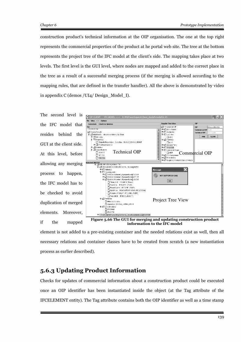
Chapter 6 Prototype Implementation
construction product's technical information at the OIP organisation. The one at the top right
represents the commercial properties of the product at he portal web site. The tree at the bottom
represents the project tree of the IFC model at the client's side. The mapping takes place at two
levels. The first level is the GUI level, where nodes are mapped and added to the correct place in
the tree as a result of a successful merging process (if the merging is allowed according to the
mapping rules, that are defined in the transfer handler). All the above is demonstrated by video
in appendix C (demos /UI4/ Design_Model_I).
The second level is
the IFC model that
resides behind the
GUI at the client side.
At this level, before
allowing any merging
process to happen,
the IFC model has to
be checked to avoid
duplication of merged
elements. Moreover,
if the mapped
element is not added to a pre-existing container and the needed relations exist as well, then all
necessary relations and container classes have to be created from scratch (a new instantiation
process as earlier described).
5.6.3 Updating Product Information
Checks for updates of commercial information about a construction product could be executed
once an OIP identifier has been instantiated inside the object (at the Tag attribute of the
IFCELEMENT entity). The Tag attribute contains both the OIP identifier as well as a time stamp
139
Figure 5.66 The GUI for merging and updating construction productinformation to the IFC model
Technical OIP
Project Tree View
Commercial OIP
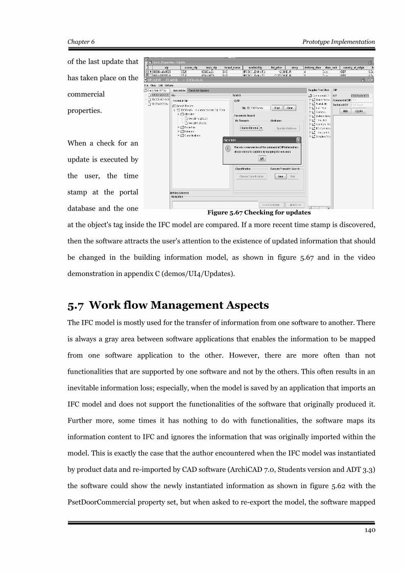
Chapter 6 Prototype Implementation
of the last update that
has taken place on the
commercial
properties.
When a check for an
update is executed by
the user, the time
stamp at the portal
database and the one
at the object's tag inside the IFC model are compared. If a more recent time stamp is discovered,
then the software attracts the user's attention to the existence of updated information that should
be changed in the building information model, as shown in figure 5.67 and in the video
demonstration in appendix C (demos/UI4/Updates).
5.7 Work flow Management Aspects
The IFC model is mostly used for the transfer of information from one software to another. There
is always a gray area between software applications that enables the information to be mapped
from one software application to the other. However, there are more often than not
functionalities that are supported by one software and not by the others. This often results in an
inevitable information loss; especially, when the model is saved by an application that imports an
IFC model and does not support the functionalities of the software that originally produced it.
Further more, some times it has nothing to do with functionalities, the software maps its
information content to IFC and ignores the information that was originally imported within the
model. This is exactly the case that the author encountered when the IFC model was instantiated
by product data and re-imported by CAD software (ArchiCAD 7.0, Students version and ADT 3.3)
the software could show the newly instantiated information as shown in figure 5.62 with the
PsetDoorCommercial property set, but when asked to re-export the model, the software mapped
140
Figure 5.67 Checking for updates
Chapter 6 Prototype Implementation
its objects to a STEP file and took no care of the extra information in the model. Hence, the IFC
model looses its advantage as an independent non proprietary building information model that is
capable of transmitting multidisciplinary AEC information if it is used in such a manner.
Consequently, either the way of use has to be changed or the software developers have to change
their strategies. Moreover, it has been proved now that the scenario of the incremental
development of a single building information model that has been presented by the IAI since
1996 has not been achieved.
Researchers like (Kiviniemi et al 2005a) and (Haymaker et al 2003) argue that the existing
software products can not support all features of the IFC model. Furthermore, they emphasis the
fact that there are no potential customers for applications that cover all different information
needs due to the fragmented nature of the AEC industry. Hence, they believe that for a building
project, there should be several instantiated models where the shared information should be
linked together across the models, i.e. without merging the models together in one model. The
latter might be a way of use that can overcome the above mentioned work flow problems.
At the time of writing this thesis, there are three major trials to solve this problem by developing
IFC model servers since the year 2001. These trials are (ImSvr 2001), (WebSTEP 2003) and
(EPM 2003). All of these models provide partial model information exchange. However, the
concept of a multi-model environment has not been tested in real projects. (Kiviniemi et al
2005b). It should be mentioned that the author's software is capable of without information loss.
5.8 Summary & Conclusions
The aim of this chapter was to present a proof of concept to the idea of linking technical and
commercial construction product life-cycle data to the IFC model in a trial to help providing
Building Information Models with up-to-date product data all over the life-cycle of the building.
The work in this chapter simulated a distributed network application that represents all the
141
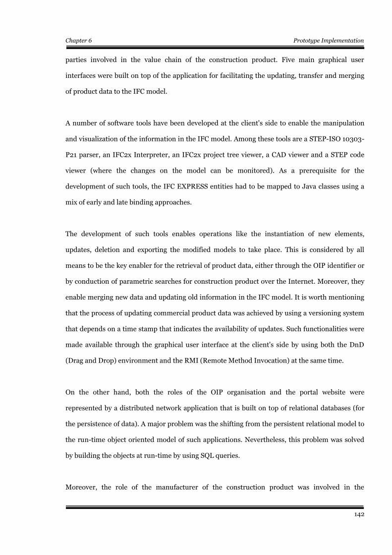
Chapter 6 Prototype Implementation
parties involved in the value chain of the construction product. Five main graphical user
interfaces were built on top of the application for facilitating the updating, transfer and merging
of product data to the IFC model.
A number of software tools have been developed at the client's side to enable the manipulation
and visualization of the information in the IFC model. Among these tools are a STEP-ISO 10303-
P21 parser, an IFC2x Interpreter, an IFC2x project tree viewer, a CAD viewer and a STEP code
viewer (where the changes on the model can be monitored). As a prerequisite for the
development of such tools, the IFC EXPRESS entities had to be mapped to Java classes using a
mix of early and late binding approaches.
The development of such tools enables operations like the instantiation of new elements,
updates, deletion and exporting the modified models to take place. This is considered by all
means to be the key enabler for the retrieval of product data, either through the OIP identifier or
by conduction of parametric searches for construction product over the Internet. Moreover, they
enable merging new data and updating old information in the IFC model. It is worth mentioning
that the process of updating commercial product data was achieved by using a versioning system
that depends on a time stamp that indicates the availability of updates. Such functionalities were
made available through the graphical user interface at the client's side by using both the DnD
(Drag and Drop) environment and the RMI (Remote Method Invocation) at the same time.
On the other hand, both the roles of the OIP organisation and the portal website were
represented by a distributed network application that is built on top of relational databases (for
the persistence of data). A major problem was the shifting from the persistent relational model to
the run-time object oriented model of such applications. Nevertheless, this problem was solved
by building the objects at run-time by using SQL queries.
Moreover, the role of the manufacturer of the construction product was involved in the
142

Chapter 6 Prototype Implementation
distributed network application through a simple graphical user interface that enabled the
registration of the product's technical data at the OIP organization, in addition to the allocation of
an OIP technical identifier.
Finally, the chapter ended with a work flow management remark. It was noticed that the
commercial applications like ArchiCAD 7.0 from Graphisoft and ADT (Architectural Desktop)
from Autodesk could successfully import the IFC model that is exported from the author's
software and they could display some of the newly instantiated data that is not CAD related.
However, when it was required to export the model, an inevitable loss of information was
encountered. Reasons that might be standing behind such an information loss were mentioned
together with the provision of some guidelines that might be able to help rectify such problems.
This aspect might be one of the recommendations for further research in this field.
143
Chapter 6 Prototype Implementation
Chapter 6
Conclusions and recommendations forfurther research
6.1 Conclusions
This thesis established a flexible and dynamic building information model with the ability to
access, query and update information about construction products. Moreover, it tried to establish
a link between products in the building information model from one side and their information at
the manufacturers' and suppliers' data repositories from the other side. This is envisaged to
provide open access to the manufacturer's and supplier's product information by enabling both
product parameter and global unique identification.
By viewing the literature and the state-of-the-art of electronic product catalogues, it was found
that the majority of commercial product catalogue vendors still depend on a free text HTML or
PDF information content that is searched by keywords. The latter is not reusable by electronic
means for design purposes and is not able to be mapped and merged to building information
models. At the CAD vendors level, it has been found that they do not support parametric
searches, where it is of paramount importance not only to hand-specify the product's parameters,
but also to extract the parameters from the existing building information model. Moreover, most
trials were proprietary commercial developments that resulted in the incapability of transferring
data to a foreign environment without information loss. Furthermore, the freedom to structure
data about product properties without following any standards leads more often than not to the
inability to communicate meanings. Meanwhile, the majority of independent research projects
were more focused on building new taxonomies and ontologies that can be implemented by XML
for communication of meanings. They are more often than not depending on a central database
144

Chapter 6 Prototype Implementation
that can be accessed over the Internet.
By investigating the life-cycle of construction products, together with their value and supply
chains, it was found that there is not only a need for life-cycle information, but also for
information over the whole life-cycle of the product. Meanwhile, from a commercial point of
view, it was also found that suppliers usually sell products from the same manufacturer, but
under different brand names. The role of the brand name in the marketing strategies was
investigated and emphasized as a major player in marketing strategies. Also the role of
middlemen was emphasized even for transactions that take place over the Internet. Furthermore,
the fact that construction products have the peculiarity that they can be partially or wholly
fabricated on site had to be reflected on the design of any information system that tries to address
the construction product's value chain.
The work has also concluded that the idea of construction product global unique identification
together with the support of other types of searches and especially the parametric searches might
help in changing the current status. Furthermore, the IFC model with its non-proprietary
characteristics, its multidisciplinary nature and published property sets is a considerable
candidate for any prototype development.
Returning to the main point concerning the suggested solution concept, the work has introduced
the OIP (Object Information Pack) that can be used as a permanent and dynamic source of data
to Building Information Models. The OIP is not just a global unique identifier; it is an
information data structure. It consists of a three layers hierarchy that is reflected in its database
structure which is managed by a group of relations that reside in the OIP kernel. The design of
the OIP identifier itself and the distribution of the products data among several parties and
databases ( technical data at the OIP organisation and commercial data at suppliers and portal
websites) is considered to be a key change to the use of the single central database, as it has been
done in previous research projects. The solution concept in this work was developed from a close
145
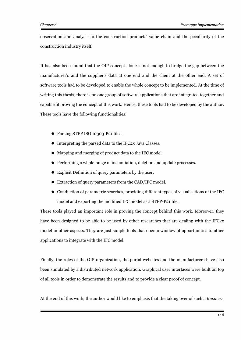
Chapter 6 Prototype Implementation
observation and analysis to the construction products' value chain and the peculiarity of the
construction industry itself.
It has also been found that the OIP concept alone is not enough to bridge the gap between the
manufacturer's and the supplier's data at one end and the client at the other end. A set of
software tools had to be developed to enable the whole concept to be implemented. At the time of
writing this thesis, there is no one group of software applications that are integrated together and
capable of proving the concept of this work. Hence, these tools had to be developed by the author.
These tools have the following functionalities:
● Parsing STEP ISO 10303-P21 files.
● Interpreting the parsed data to the IFC2x Java Classes.
● Mapping and merging of product data to the IFC model.
● Performing a whole range of instantiation, deletion and update processes.
● Explicit Definition of query parameters by the user.
● Extraction of query parameters from the CAD/IFC model.
● Conduction of parametric searches, providing different types of visualisations of the IFC
model and exporting the modified IFC model as a STEP-P21 file.
These tools played an important role in proving the concept behind this work. Moreover, they
have been designed to be able to be used by other researches that are dealing with the IFC2x
model in other aspects. They are just simple tools that open a window of opportunities to other
applications to integrate with the IFC model.
Finally, the roles of the OIP organization, the portal websites and the manufacturers have also
been simulated by a distributed network application. Graphical user interfaces were built on top
of all tools in order to demonstrate the results and to provide a clear proof of concept.
At the end of this work, the author would like to emphasis that the taking over of such a Business
146
Chapter 6 Prototype Implementation
Process Re-engineering (BPR) in the industry practice is not free of problems and barriers. It is
well known from the literature of organizational cultures and psychology that users are always
reluctant to the implementation of revolutionary systems that change the traditional ways of
doing things, (even if it results in a more optimisation and efforts saving on the long run).
However, the change of current practice can still be achieved by the commitment of the top
management of major market players together with convincing users with the advantages of the
new systems and making them feel it on the ground.
6.2 Review of chapters
Chapter 2 responds to the first objective of the thesis (chapter one, section 1.2.2). It is a review
of the literature of linking construction product data to building information models. It concludes
that most of the commercial product catalogue vendors are oriented towards text based searches.
Moreover, many research projects are designed to work around a central database, where data
transfer and communication of meaning is a main research point that is out of the scope of this
work. On the other hand, many projects have tried to link product data to CAD environments.
However, it was found that the product selection process is still confined to navigating web pages
at the hosting website. Furthermore, the majority of such CAD integrated systems are proprietary
developments that result in an inevitable information loss by shifting to other CAD
environments.
Chapter 3 responds to the second and third objectives of the thesis (chapter one, section 1.2.2).
It includes an analysis of the construction product's value chain and its marketing strategies. It
identifies the key barriers for the lack of integration between construction product data and
Building Information Models. It puts forward a set of guidelines for any concept of a solution
development that wants to benefit from the literature and state-of-the-art analysis that has been
made in the previous chapters.
147

Chapter 6 Prototype Implementation
Chapter 4 responds to objective number four of the thesis. It provides a concept of a solution
that implements the guidelines that were identified in chapter three. It provides a definition of
the concept supported by examples and scenarios of use.
Chapter 5 or part II of the thesis responds to objectives number five, six and seven (chapter one,
section 1.2.2). It proves the suggested solution concept in chapter four. It identified the need to
particular software tools that are essential for proving the solution concept together with the
needed programming technologies that have to be learned and used. Example of such
technologies are the Java Compiler Compiler technology for parsing the STEP-ISO 10303-P21
files, the JAVA 2D package for visualization, Java RMI and sockets for communication EXPRESS
,STEP and so forth. An open distributed software platform that simulates and validates the
solution's concept has been tested with real life data models.
6.3 Recommendations for further studies and concept
development
6.3.1 Further studies
It has been proved that a construction product can be linked all over its whole life-cycle to its data
sources. It is hoped that this would open a window of opportunities for multidisciplinary AEC-
FM software applications to benefit from such flexibility that allows both the richness and reach
of construction product information. Hence, any further use of the building information model in
a manner that makes use of its ability to get hold of external up-to-date construction products
information is considered to be an emphasise to the success of this research work.
Among such applications are the conduction of virtual experiments and simulations, not only to
select construction products on the basis of performance criteria, but also in many other fields
such as: The prediction of the structural behaviour of buildings and materials under different
conditions e.g. earthquakes, energy performance, in computational fluid dynamics (CFDs) and
ventilation or even the acoustical design and so forth.
148
Chapter 6 Prototype Implementation
In addition, the concept could be applied to the area of collaborative work. Different AEC-FM
disciplines who work on the same building information model(s), try to achieve the consistency
of the model and ensure its validity by establishing consistent versions of the model. If the
external links from the model to the products' data are valid, up-to-date and consistent with the
design versions, then a reliable model can be achieved.
6.3.2 Concept development
The work in this thesis has only implemented the product part of the OIP concept. The OIP
model is designed in an extensible manner that enables the addition and implementation of new
aspects such as construction services and activities. Nevertheless, this necessitates that the model
should not only include product modelling but also process modelling aspects as well. These
activities or processes can then be linked to the project planning processes, where the allocation
of resources, time scheduling and site layout planning are of great need to the electronic transfer
of such information.
Another development could be achieved in the area of construction products and materials
resides in the potentiality of improving their logistics by using the OIP unique identifier as a part
of a product instance identifier (as a serial number or a bar code). It can facilitate the tracing and
monitoring of the product or material throughout the value chain and its whole life-cycle. This
might be able to play an important role in Material Requirement Planning (MRP) of construction
products, where scheduling, site layout planning and inventory could be planned accordingly.
149

References
ReferencesAecXML 1999. Architecture, Engineering and Construction XML, Bentley Systems, USA.http://www.iai-na.org/aecxml/mission.php
Amor, R. Jain, S. and Augenbroe, G. 2004. Online Product Libraries, the State of the -art,Proceedings of the CIB Triennial, Toronto, Canada, 3-7 May.
Amor, R. and Kloep, W. 2003. E-Product Catalogues, Proceedings of the EIA9 Conference onEactivities and Intelligent Support in Design and the Built Environment, Istanbul, Turkey, 2-8October.
Amor, R., Finne, C., Turk, Z. and Hyvarinen, J. 2000. CONNET: CONstruction information service.NETwork, Final report, EC-ETTN-Lot 4, Contract 501999, March, pp. 71.
Amor, R. and Newnham, L. 1999. CAD Interfaces to the ARROW Manufactured Product Server,Proceedings of CAADfutures'99, Atlanta, USA, 7-8 June, pp. 1-12.
Augenbroe, G. 1998. Building Product Information Technology, Executive white paper, GeorgiaInstitute of Technology, http://www.arch.gatech.edu/crc/ProductInfo/
Autodesk 2003. Architectural Desktop http://www.autodesk.com/
AutoDesk, 2004. i-drop Technology , Autodesk developer center, http://usa.autodesk.com
Behrman, W. 2002. Best Practice for the development and use of XML Data Interchange Standards.CIFE Technical Report TR131, Stanford University 2002, available athttp://cife.stanford.edu/online.publications/TR131.pdf
Birchfield E. B. and King H. H., 1985. “Product Data Definition Interface (PD-DI),” Proc. of the1985 USAF CIM Industry Days, Texas, April 1985.
Björk B.-C. (2003). Electronic document management in construction - research issues and results,Electronic Journal of Information Technology, Vol. 8, pg. 105-117, http://www.itcon.org
BMEcat 2003. eBusiness Standardization Committee, www.bmecat.org
Building 90 1999. The Finnish Building Classification System, The Finnish Building Centre ,Helsinki, ISBN 951-682-580-x, http://www.rts.fi/talo-nimikkeisto/building90.pdf
Coase R. H. 1988. The firm, the market and the law, Chicago, USA.
Coltman T., Devinney T. M., Latukefu A., Midgley D. F. (2001). E-Business: Revolution, evolution,or hype?, California Management Review, Berkeley, USA.
Construct IT 2004. Building Product Libraries, http://cic.vtt.fi/links/prodlib.html
Cook, G., Czubayko, R., Klemme, R., 1999. PROCAT-GEN – Conformance Specification,http://www.procat-gen.org/
150
References
Cope, G. and Amor, R.W. 2002. UDDI for a Manufactured Product Brokering Service, Proceedingsof the EC-PPM Conference on eWork and eBusiness in AEC, Portoroz, Slovenia, 9-11 September, pp.603-608.
Coyne, R., Lee, J., Duncan, D. and Ofluoglu, S. 2001. Applying Web-Based Product Libraries,Automation in Construction, Vol 10, No 5, pp. 549-559.
CSI MasterFormat 2003. Construction Specifications Institute, http://www.csinet.org/
Debras, P. 2000. Construction Application of a GEN-Network: Uniform Access to Standards,Products and Company Information, Proceedings of CIB W78 Construction Information Technology2000, Reykjavik, Iceland, 28-30 June.
Diaz, J. 2004. In Dikbas & Sherer (ed),. Comprehensive information exchange for the constructionindustry, Proceedings of the ICCBE conference on eWork and eBusiness in Architecture,Engineering and Construction, Istanbul, Turkey 2-10 September.
Eastman C. M. (1999). Building Product Models – Computer Environments Supporting Design andConstruc-tion, CRC Press, Boca Raton, Florida, USA.
eCl@ss 2004, Standardized Material and Service Classification, http://www.eclass-online.com/
eConstruct 2000, Electronic business in the Building and Construction Industry, EU IST-10303,http://www.econstruct.org
EDF 2004, Electronic Design Interchange Format, http://www.edif.org/
EPIC 1999. Electronic Product Information Co-operation, http://www.epicproducts.org/
EPM Technology 2002, STEP/EXPRESS Implementation course, Darmstadt, Germany, October 22– 25. at PropSTEP AG.
EPM Technology 2004, Express Data Manager (EDM), http://www.epmtech.jotne.com/
Faux, I., Radeke, E., Stewing, F.-J., van der Broek, G., Kesteloot, P. and Sabin, A. 1998.
Intelligent Access, Publishing, and Collaboration in the Global Engineering Networking, ComputerNetworks and ISDN Systems, Vol 30, No 13, August, http://www.procat-gen.org/
Finne, C. 2003. How the Internet is changing the role of construction information middlemen: Thecase of construction information services, ITcon, Vol. 8 (2003), http://www.itcon.org/2003/27/,pp. 397-411.
Firmenich, Berthold 2004. Script CAD in der Bauinformatik, Bauhaus University, Weimar.
Foley James D., Van Dam A., Feiner S., Hughes J., Phillips R. 1996. Introductions to ComputerGraphics, Addison- Wesley, USA.
Ganeshan. R, and Harrison, T. P. (1995), Introduction to Supply Chains Management, Penn StateUniversity, USA.
151
References
Graphisoft 2004. http://www.graphisoft.com/
Hardy Vincent J. 2000. Java 2D API Graphics, The SUN Microsystems Press, Java Series, USA.ISBN 0-13—014266-2
Haymaker, J. Souter, B. Kunz, J. and Fischer M. 2003. PERSPECTORS: Automating theconstruction and Coordination of Multidisciplinary 3D design Representations. CIFE TechnicalReport TR145, Stanford Universtiy 2003. http://cife.stanford.edu/online.publications/TR145.pdf
IAI International Alliance for Interoperability, www.iai-international.org/iai_international/
IFC2x Model Implementation Guide 2002. International Alliance for Interoperability, ThomasLiebig (ed), Modelling Support Group, Version 1.4, 5th of July 2002.
IFC 2003. International Alliance for Interoperability, http://www.iai-international.org/
ifcXML 2001. XML schema language binding of EXPRESS for ifcXML, Thomas Liebich.,http://www.iai-international.org/iai_international/Technical_Documents/documentation/IFCXML/ifcXML_language_binding_V1-02.pdf
IGES 1980, Initial Graphics Exchange Specification, Version 1.0, NIST, Gaithersburg, Maryland,January 1980.
ISO 10303-11 EXPRESS 1994. Industrial automation systems and integration – Product datarepresentation and exchange – part 11: Description methods: The EXPRESS language referencemanual.
ISO 10303-21 STEP 1994. Industrial Automation Systems and Integration — Product DataRepresen-tation and Exchange — Part 21: Implementation Methods: Clear Text En-coding of theExchange Structure, ISO 10303-21:1994 (E), ISO, Geneva, 1994.
ISO 10303- 21 STEP 2002. Industrial automation systems and integration – Product datarepresentation and exchange – part 21: Implementation methods : Clear text encoding for exchangestructure.
ISO 10303-22 1995. SDAI. Industrial Automation Systems and Integration — Product DataRepresen-tation and Exchange — Part 22: STEP Data Access Interface, ISO Docu-ment TC184/SC4WG7 N392, July 1995.
ISO 10303-22 1995. SDAI C++ Early Binding. Industrial Automation Systems and Integration —Product Data Represen-tation and Exchange — Part 23: C++ Language Binding to the StandardData Access Interface Specification, ISO Document TC184/SC4 WG7 N393, July 1995.
ISO 10303-22 1995. SDAI C-language Late Binding. Industrial Automation Systems andIntegration — Product Data Representation and Exchange — Part 24: Standard Data AccessInterface — C Language Late Binding, ISO Document TC184/SC4 WG7 N394, July 1995.
ISO 10303-22 1994. Industrial Automation Systems and Integration — Product Data Represen-tation and Exchange — Part 42: Integrated Generic Resources: Geometric and Topological
152
References
Representation, ISO 10303-42:1994 (E), ISO, Geneva, 1994.
ISO 10646 2003. Universal Multiple-Octet Coded Character Set (UCS) -- Part 1: Architecture andBasic Multilingual Plane,http://www.iso.ch/iso/en/CatalogueDetailPage.CatalogueDetail?CSNUMBER=2981934
ISO 13584 PLIB 1995. Industrial Automation Systems and Integration, Parts Library,http://www.plib.ensma.fr/
ISO/DPAS 12006-3 2003. A Framework for Object Oriented Exchange in BC, http://www.sai-global.com
ITCON 2003. Electronic Journal of Information Technology in Construction, A special issue on IFC- Product models for the AEC arena, guest editor Väino Tarandi, http://www.itcon.org
Jain, S. and Augenbroe, G. 2003. A Methodology for Supporting Product Selection fromEcatalogues, ITcon, Vol. 8, http://www.itcon.org/2003/27/, pp. 381-396.
Java Compiler Compiler(Java CC) 2005. The Java Parser Generator, obtained fromhttps://javacc.dev.java.net The source for Java Technology Collaboration, Java. NET.
Kim I., Liebich T., Kim S. 2002. Development of a Two Dimensional Model Space Extension forIAI/IFC2x.x2nd Model.
Kiviniemi A., Fischer M., Bazjanac V. 2005a. Multi-model Environment: Links between Objects inDifferent Building Models. In: Scherer R., Katranuschkov P. and Schapke S. (eds.) Proceedings ofthe 22nd CIB-W78 Conference on Information Technology in Construction. Dresden: Institute ofConstruction Informatics, July 2005. - ISBN 3-86005-478-3.
Kiviniemi A., Fischer M., Bazjanac V. 2005b. Integration of Multiple Product Models: IFC ModelServer as a Potential Solution. In: Scherer R., Katranuschkov P. and Schapke S. (eds.) Proceedings ofthe 22nd CIB-W78 Conference on Information Technology in Construction. Dresden: Institute ofConstruction Informatics, July 2005. - ISBN 3-86005-478-3.
Koivu T. J. 2002. Future of product modeling and knowledge sharing in the fm/aec industryElectronic Journal of Information Technology, Vol. 7, 2002, http://www.itcon.org
Kroszynski U., Palstroem B., Trostmann E and Schlechtendahl E., 1989. “Geo-metric Data TransferBetween CAD Systems: Solid Models,” IEEE Com-puter Graphics and Applications, September1989, pp. 57-71.
Loffredo David 2004. Fundamentals of STEP Implementation, STEP Tools Inc. RensselaerTechnology Park, Troy, New York 12180, available from www.steptools.com/library/fundimpl.pdf
Newnham, L. and Amor, R. 1998. Translation of Manufacturer's Product Data for the ARROWProduct Search System, Proceedings of 2nd European Conference on Product and ProcessModelling, London, UK, 19-21 October, pp. 405-412.
Nicholson-Cole, D. 2000. The GDLCookBook-2, Teach yourself GDL by the Cookbook method &ArchiCAD's Tips and Tricks, Marmalade Graphics, Nottingham, UK.
153

References
Nour, M., Beucke, K. 2003. OIP as a base for Information Modelling in Construction. In: Kirschke,H.(ed.): Digital Proceedings des Internationalen Kolloquiums über Anwendungen der Informatikund Mathematik in Architektur und Bauwesen (IKM). Weimar: Bauhaus-Universität Weimar, Juni2003. - ISSN 1611-4086
Nour, M. 2003. Modelling of Construction Materials in IFC. In: Kaapke, K.; Wulf, A. (eds.): 15.Forum Bauinformatik. Aachen: Shaker Verlag, Reihe Bauinformatik, Oktober 2003. - ISBN 3-8322-2022-4. - ISSN 1612-6262, S. 260-274
Nour, M., Beucke, K. 2004. IFC supported distributed, dynamic and extensible constructionproducts information models. In: Dikbas, A.; Scherer, R. (eds.): Proceedings of the 5th EuropeanConference on Product and Process Modelling in the Building and related Industries : eWork andeBusiness in Architecture, Engineering and Construction. Leiden/ London/ New York u.a.: A. A.Balkema Publishers, September 2004. - ISBN 04 1535 938 4
Nour, M. M. 2004. A STEP ISO-10303 Parser, 16th Forum Bauinformatik . In Jan Zimmermann,Sebastian Geller (eds), Braunschweig. Shaker Verlag, Aachen. October 2004, pp. 231 – 237. ISBN 3-8322-3233-4
Nour, M., Beucke, K. 2005. Manipulating IFC model data in conjunction with CAD. In: Scherer, R.J.; Katranuschkov, P.; Schapke, S.-E. (eds.): Proceedings of 22nd CIB-W78 Conference onInformation Technology in Construction. Dresden: Institute of Construction Informatics, July 2005.- ISBN 3-86005-478-3
Nour, M 2005. 17th Forum Bauinformatik . CAD visualization of IFC Models. In Schley F., Weber L.(eds). Brandenburg University of Technology at Cottbus, Germany, Septemeber 2005. ISBN 3-934934-11-0
Nyambayo, J., Amor, R., Faraj, I. and Wix, J. 2000. External Product Library - An Implementationof the Industry Foundation Classes Release 2.0 Model, Proceedings of Product Data TechnologyEurope 2000, Noordwijk, The Netherlands, 2-5 May, pp. 147-156.
Obonyo, E.A., Anumba C.J., Thorpe, A. and Parkes B. 2001. Specification and Procurement ofConstruction Products: Potential Role of Intelligent Agents, Proceedings of the InternationalConference on Intelligent Agents, Web Technologies and Internet Commerce (IAWTIC'2001), LasVegas, USA, 9-11 July, pp. 268-279.
Ofluoglu, S. 2003. Interactive building product information in the context of e-commerce world,Proceedings of EIA9, Istanbul, Turkey, 8-10 October, pp. 141-150.
PDDI 1984. Product Data Definition Interface, Technical Reports DR-84-GM-01 through DR-84-GM-05, CAM-I Inc., Arlington, Texas, 1984.
Porter M. E. 1998. Competitive Advantage, New York 1998.
Pocsai, Z., Debras, P., Gui, J.-K., Hagemann, D., Seifert, L. and Stumpf, D. 1998. The CommonSemantic Model in GENIAL: A Critical Gateway towards an Intelligent Access to ComponentLibraries and Engineering Knowledge, Proceedings of Product Data Technology Days, 24-26 March,London, UK.
Ray-Jones, A. and Clegg, D. 1991. CI/SfB Construction Indexing Manual, RIBA Publications. Resse,
154

References
G. 2000. Database programming with JDBC and Java, O'Reilly 2000, ISBN 1-565-92616-1
RINET 2000. RINET – Building product database, http://cic.vtt.fi/projects/rinet/rinet.html
Romo I. (2002a). ICT in the Construction Industry Technology Strategy, IAI ITM Evening April23rd 2002, http://cic.vtt.fi/vera
Romo I. (2002b). Rakennusklusterin teknologiaohjelman sisältötyöryhmän raportti, (Final report ofthe contents work group for the Technology Programme for the Construction Cluster 2003-2007)Tekes PM 10.12.2002
Sarkar, M. B., Buttler, B. and Steinfeld, C. 1995. Intermediaries and Sybermediaries: A continuingrole for mediating players in the electronic market place, Journal of Computer-MediatedCommunication, Vol 1, 1995, Issue 3, http://www.ascusc.org/jcmc/vol1/issue3/sarkar.html
Schenck D. and Wilson P. 1994. Information Modeling the EXPRESS Way, Oxford UniversityPress, New York, 1994. ISBN 0-19-508714-3.
SET 1985. Automatisation industrielle. Representation externe des donnees de defini-tion deproduits. Specification du standard d’echange et de transferts (SET), Version 85-08, Z68-300,Association Francaise de Normalisation (AFNOR) 85181, Paris, 1985.
Shapiro C. and Varian H. R. 1999a. Information Rules: A Strategic Guide to the Network Economy,Boston, Massachusetts, USA.
Shapiro C. and Varian H. R. 1999b The art of standard wars, California Management Review; Vol.41, 1999, Issue 2, Berkeley, USA.
Shocklee, M., Burkett, B. and Yang, Y., 1999. Product Data Markup Language (PDML Specification,http://www.pdit.com/pdml/
Smith R. A. (2001). Trends in e-business technologies, IBM Systems Journal, Vol. 40, 2001, Issue 1,Armonk
Smith M. D. and Brynjolfsson E. 2001. Consumer Decision-Making at an Internet Shopbot: BrandStill Mat-ters, The Journal of Industrial Economics, vol. 49, 2001, Issue 4
Timm, U and Rosewitz, M. 1998. Electronic sales assistance for product configuration. InProceedings of the 11th International Bled Electronic Commerce Conference – Electronic Commercein the Information Society, Bled, Slovenia, 1, pp. 8-10
Tolman, Van Rees, R., Böhms, M.2001. Delft University of Technology (NL), TNO Building andConstruction Research (NL), Building and Construction Extensible Mark-Up Language (bcXML):The C2B / B2C Scenario.
Van Leeuwen, J.P. and Fridqvist, S. 2002. On the Management of Sharing Design Knowledge,Proceedings of the CIB W78 conference on Distributing Knowledge in Building, Vol 1, Aarhus,Denmark, 12-14 June, pp. 235-242.
VDAFS 1986. VDA Flaechenschnittstelle , Version 1.0, Deutsches Institute für Normung (DIN)
155

References
66301, Beuth Verlag, Berlin, 1986.
Wikipedia 2005. The Free Encyclopaedia, Tree Traversals, traversal methods, Post Order RecursiveTraversal: http://en.wikipedia.org/wiki/Post-order_traversal#Traversal_methods
Willcocks L. P., Plant R. 2001. Pathways to e-business leadership: Getting from bricks to clicks, MitSloan Management Review, Vol. 42, 2001, Issue: 3
Wilson P. R. 1987, “A Short History of CAD Data Transfer Standards,” IEEE Computer Graphics andApplications, Vol.7, No. 6, June 1987, pp. 64-67.
Wimmer B. S., Townsend A. M. and Chezum B. E. (2000). Information Technologies and theMiddleman: The Changing Role of Information Intermediaries in an Information Rich Economy,Journal of Labour re-search, Vol. 21, 2000, Issue 3
Woestenenk, K. 2002. The LexiCon: structuring semantics, Proceedings of CIB W78 conference onDistributing Knowledge in Building, Vol 2, Aarhus, Denmark, 12-14 June, pp. 241-247.
Öörni A., Klein S. 2003. Electronic travel markets: Elusive Effects on Consumer Behaviour, workingpaper, The Swedish School of Economics and Business Administration, Helsinki.
156
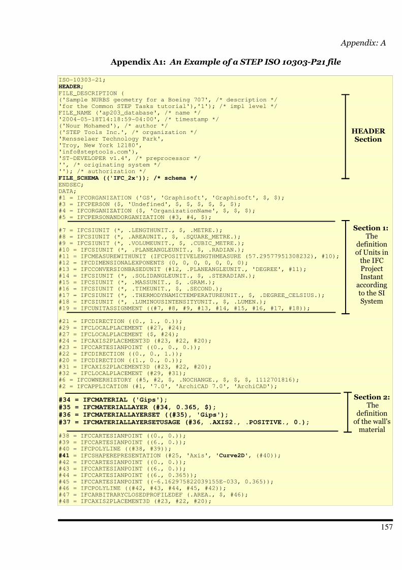
Appendix: A
Appendix A1: An Example of a STEP ISO 10303-P21 file
ISO-10303-21;
HEADER;FILE_DESCRIPTION (
('Sample NURBS geometry for a Boeing 707', /* description */
'for the Common STEP Tasks tutorial'),'1'); /* impl level */
FILE_NAME ('ap203_database', /* name */
'2004-05-18T14:18:59-04:00', /* timestamp */
('Nour Mohamed'), /* author */
('STEP Tools Inc.', /* organization */
'Rensselaer Technology Park',
'Troy, New York 12180',
'ST-DEVELOPER v1.4', /* preprocessor */
'', /* originating system */
''); /* authorization */
FILE_SCHEMA (('IFC_2x')); /* schema */ENDSEC;
DATA;
#1 = IFCORGANIZATION ('GS', 'Graphisoft', 'Graphisoft', $, $);
#3 = IFCPERSON ($, 'Undefined', $, $, $, $, $, $);
#4 = IFCORGANIZATION ($, 'OrganizationName', $, $, $);
#5 = IFCPERSONANDORGANIZATION (#3, #4, $);
#7 = IFCSIUNIT (*, .LENGTHUNIT., $, .METRE.);
#8 = IFCSIUNIT (*, .AREAUNIT., $, .SQUARE_METRE.);
#9 = IFCSIUNIT (*, .VOLUMEUNIT., $, .CUBIC_METRE.);
#10 = IFCSIUNIT (*, .PLANEANGLEUNIT., $, .RADIAN.);
#11 = IFCMEASUREWITHUNIT (IFCPOSITIVELENGTHMEASURE (57.29577951308232), #10);
#12 = IFCDIMENSIONALEXPONENTS (0, 0, 0, 0, 0, 0, 0);
#13 = IFCCONVERSIONBASEDUNIT (#12, .PLANEANGLEUNIT., 'DEGREE', #11);
#14 = IFCSIUNIT (*, .SOLIDANGLEUNIT., $, .STERADIAN.);
#15 = IFCSIUNIT (*, .MASSUNIT., $, .GRAM.);
#16 = IFCSIUNIT (*, .TIMEUNIT., $, .SECOND.);
#17 = IFCSIUNIT (*, .THERMODYNAMICTEMPERATUREUNIT., $, .DEGREE_CELSIUS.);
#18 = IFCSIUNIT (*, .LUMINOUSINTENSITYUNIT., $, .LUMEN.);
#19 = IFCUNITASSIGNMENT ((#7, #8, #9, #13, #14, #15, #16, #17, #18));
#21 = IFCDIRECTION ((0., 1., 0.));
#29 = IFCLOCALPLACEMENT (#27, #24);
#27 = IFCLOCALPLACEMENT ($, #24);
#24 = IFCAXIS2PLACEMENT3D (#23, #22, #20);
#23 = IFCCARTESIANPOINT ((0., 0., 0.));
#22 = IFCDIRECTION ((0., 0., 1.));
#20 = IFCDIRECTION ((1., 0., 0.));
#31 = IFCAXIS2PLACEMENT3D (#23, #22, #20);
#32 = IFCLOCALPLACEMENT (#29, #31);
#6 = IFCOWNERHISTORY (#5, #2, $, .NOCHANGE., $, $, $, 1112701816);
#2 = IFCAPPLICATION (#1, '7.0', 'ArchiCAD 7.0', 'ArchiCAD');
#34 = IFCMATERIAL ('Gips');#35 = IFCMATERIALLAYER (#34, 0.365, $);#36 = IFCMATERIALLAYERSET ((#35), 'Gips');#37 = IFCMATERIALLAYERSETUSAGE (#36, .AXIS2., .POSITIVE., 0.);
#38 = IFCCARTESIANPOINT ((0., 0.));
#39 = IFCCARTESIANPOINT ((6., 0.));
#40 = IFCPOLYLINE ((#38, #39));
#41 = IFCSHAPEREPRESENTATION (#25, 'Axis', 'Curve2D', (#40));#42 = IFCCARTESIANPOINT ((0., 0.));
#43 = IFCCARTESIANPOINT ((6., 0.));
#44 = IFCCARTESIANPOINT ((6., 0.365));
#45 = IFCCARTESIANPOINT ((-6.162975822039155E-033, 0.365));
#46 = IFCPOLYLINE ((#42, #43, #44, #45, #42));
#47 = IFCARBITRARYCLOSEDPROFILEDEF (.AREA., $, #46);
#48 = IFCAXIS2PLACEMENT3D (#23, #22, #20);
157
Section 2: The
definition of the wall's material
Section 1: The
definition of Units in the IFC Project Instant
according to the SI System
HEADERSection
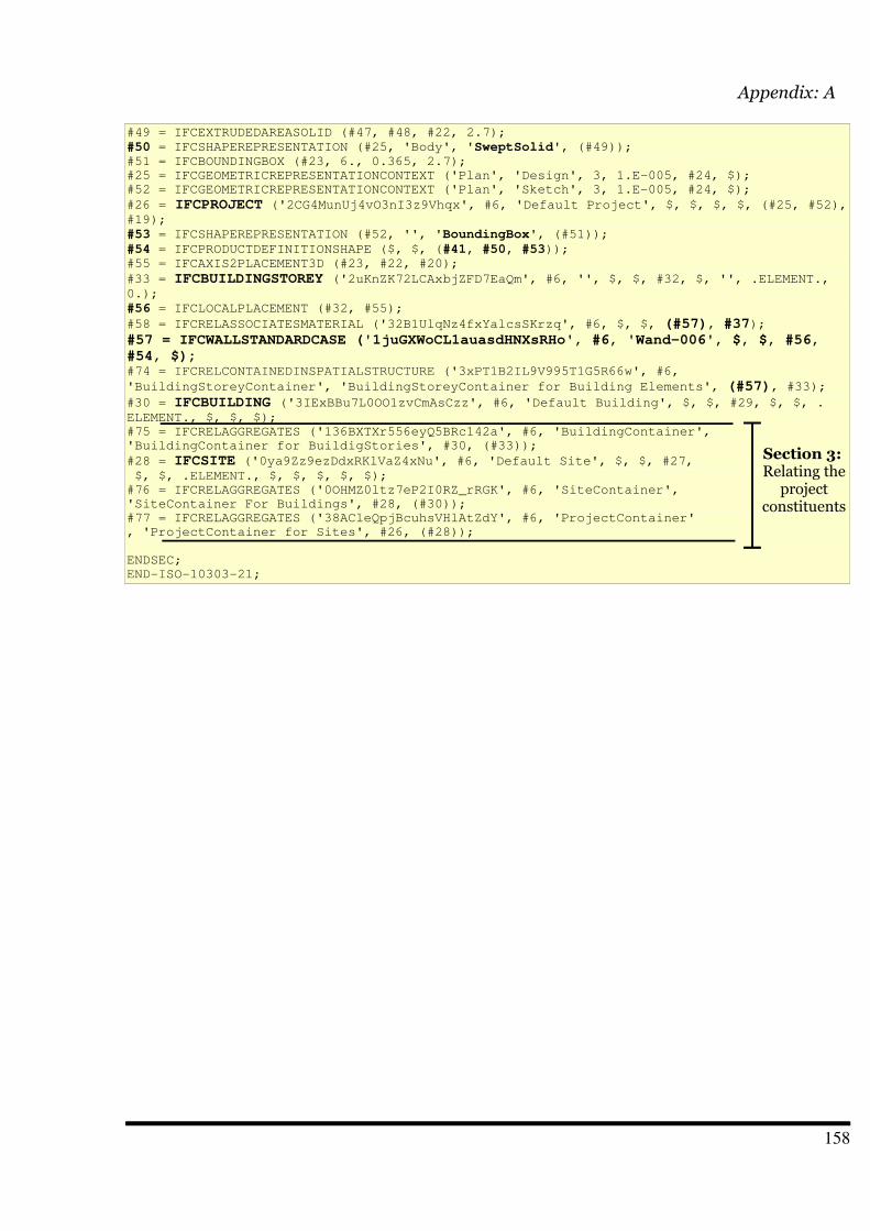
Appendix: A
#49 = IFCEXTRUDEDAREASOLID (#47, #48, #22, 2.7);
#50 = IFCSHAPEREPRESENTATION (#25, 'Body', 'SweptSolid', (#49));#51 = IFCBOUNDINGBOX (#23, 6., 0.365, 2.7);
#25 = IFCGEOMETRICREPRESENTATIONCONTEXT ('Plan', 'Design', 3, 1.E-005, #24, $);
#52 = IFCGEOMETRICREPRESENTATIONCONTEXT ('Plan', 'Sketch', 3, 1.E-005, #24, $);
#26 = IFCPROJECT ('2CG4MunUj4vO3nI3z9Vhqx', #6, 'Default Project', $, $, $, $, (#25, #52),#19);
#53 = IFCSHAPEREPRESENTATION (#52, '', 'BoundingBox', (#51));
#54 = IFCPRODUCTDEFINITIONSHAPE ($, $, (#41, #50, #53));#55 = IFCAXIS2PLACEMENT3D (#23, #22, #20);
#33 = IFCBUILDINGSTOREY ('2uKnZK72LCAxbjZFD7EaQm', #6, '', $, $, #32, $, '', .ELEMENT.,0.);
#56 = IFCLOCALPLACEMENT (#32, #55);
#58 = IFCRELASSOCIATESMATERIAL ('32B1UlqNz4fxYalcsSKrzq', #6, $, $, (#57), #37);#57 = IFCWALLSTANDARDCASE ('1juGXWoCL1auasdHNXsRHo', #6, 'Wand-006', $, $, #56,#54, $);#74 = IFCRELCONTAINEDINSPATIALSTRUCTURE ('3xPT1B2IL9V995T1G5R66w', #6,
'BuildingStoreyContainer', 'BuildingStoreyContainer for Building Elements', (#57), #33);#30 = IFCBUILDING ('3IExBBu7L0OO1zvCmAsCzz', #6, 'Default Building', $, $, #29, $, $, .ELEMENT., $, $, $);
#75 = IFCRELAGGREGATES ('136BXTXr556eyQ5BRc142a', #6, 'BuildingContainer',
'BuildingContainer for BuildigStories', #30, (#33));
#28 = IFCSITE ('0ya9Zz9ezDdxRKlVaZ4xNu', #6, 'Default Site', $, $, #27, $, $, .ELEMENT., $, $, $, $, $);
#76 = IFCRELAGGREGATES ('0OHMZ0ltz7eP2I0RZ_rRGK', #6, 'SiteContainer',
'SiteContainer For Buildings', #28, (#30));
#77 = IFCRELAGGREGATES ('38ACleQpjBcuhsVHlAtZdY', #6, 'ProjectContainer'
, 'ProjectContainer for Sites', #26, (#28));
ENDSEC;
END-ISO-10303-21;
158
Section 3: Relating the
project constituents

Appendix: A
Appendix A2: A jjdoc output of the STEP_Parser.jj grammar file for the NON-TERMIANLS.
Start ::= stepHeaderstepHeader ::= ( <ISOSTEP> <IDENTIFIER> <EOC> ( <IDENTIFIER>
<OPEN_B> argList <CLOSE_B> <EOC> )+ <ENDSEC> <DATA> )+ ifcList ( <ENDSEC><END_ISO_STEP> )+
ifcList ::= ( ifcElement )*ifcElement ::= <Line_Nr> <EQUALS> <IDENTIFIER> <OPEN_B> argList
<CLOSE_B> <EOC>argList ::= ( arg )*arg ::= <IDENTIFIER>
| <WILD> // for parsing any user defined String
| <Line_Nr> // identifier of the element (# 9 digits)
| "," //to separate between attribute values
| <ASTRISK> //attributes that are re-defined in sub-classes
| <IFC_VALUE>
| <IFC_UNIT>
| ( "+" )? numLiteral
| ( "-" )? numLiteral
| "(" argList ")"
numLiteral ::= <INTEGER_LITERAL>
| <FLOATING_POINT_LITERAL>
159
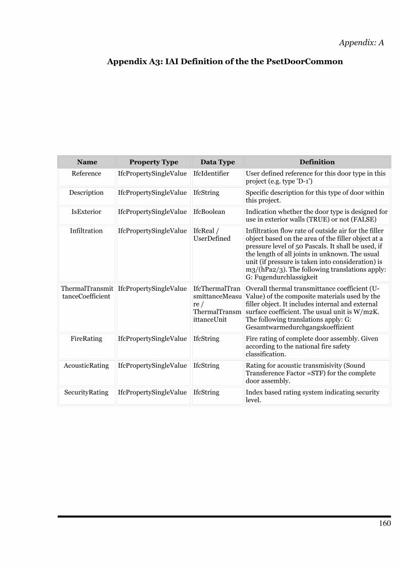
Appendix: A
Appendix A3: IAI Definition of the the PsetDoorCommon
Name Property Type Data Type Definition
Reference IfcPropertySingleValue IfcIdentifier User defined reference for this door type in thisproject (e.g. type 'D-1')
Description IfcPropertySingleValue IfcString Specific description for this type of door withinthis project.
IsExterior IfcPropertySingleValue IfcBoolean Indication whether the door type is designed foruse in exterior walls (TRUE) or not (FALSE)
Infiltration IfcPropertySingleValue IfcReal /UserDefined
Infiltration flow rate of outside air for the fillerobject based on the area of the filler object at apressure level of 50 Pascals. It shall be used, ifthe length of all joints in unknown. The usualunit (if pressure is taken into consideration) ism3/(hPa2/3). The following translations apply:G: Fugendurchlassigkeit
ThermalTransmittanceCoefficient
IfcPropertySingleValue IfcThermalTransmittanceMeasure /ThermalTransmittanceUnit
Overall thermal transmittance coefficient (U-Value) of the composite materials used by thefiller object. It includes internal and externalsurface coefficient. The usual unit is W/m2K.The following translations apply: G:Gesamtwarmedurchgangskoeffizient
FireRating IfcPropertySingleValue IfcString Fire rating of complete door assembly. Givenaccording to the national fire safetyclassification.
AcousticRating IfcPropertySingleValue IfcString Rating for acoustic transmisivity (SoundTransference Factor =STF) for the completedoor assembly.
SecurityRating IfcPropertySingleValue IfcString Index based rating system indicating securitylevel.
160
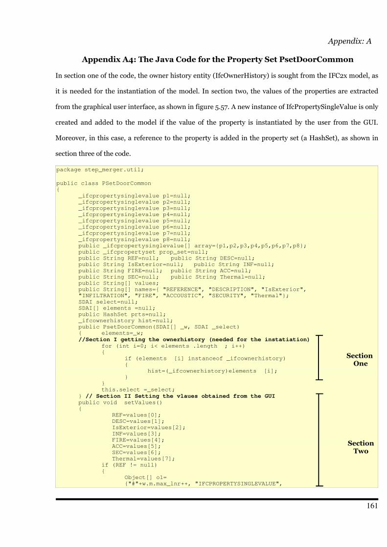
Appendix: A
Appendix A4: The Java Code for the Property Set PsetDoorCommon
In section one of the code, the owner history entity (IfcOwnerHistory) is sought from the IFC2x model, as
it is needed for the instantiation of the model. In section two, the values of the properties are extracted
from the graphical user interface, as shown in figure 5.57. A new instance of IfcPropertySingleValue is only
created and added to the model if the value of the property is instantiated by the user from the GUI.
Moreover, in this case, a reference to the property is added in the property set (a HashSet), as shown in
section three of the code.
package step_merger.util;
public class PSetDoorCommon
{
_ifcpropertysinglevalue p1=null;
_ifcpropertysinglevalue p2=null;
_ifcpropertysinglevalue p3=null;
_ifcpropertysinglevalue p4=null;
_ifcpropertysinglevalue p5=null;
_ifcpropertysinglevalue p6=null;
_ifcpropertysinglevalue p7=null;
_ifcpropertysinglevalue p8=null;
public _ifcpropertysinglevalue[] array={p1,p2,p3,p4,p5,p6,p7,p8};
public _ifcpropertyset prop_set=null;
public String REF=null; public String DESC=null;
public String IsExterior=null; public String INF=null;
public String FIRE=null; public String ACC=null;
public String SEC=null; public String Thermal=null;
public String[] values;
public String[] names={ "REFERENCE", "DESCRIPTION", "IsExterior",
"INFILTRATION", "FIRE", "ACCOUSTIC", "SECURITY", "Thermal"};
SDAI select=null;
SDAI[] elements =null;
public HashSet prts=null;
_ifcownerhistory hist=null;
public PsetDoorCommon(SDAI[] _w, SDAI _select)
{ elements=_w;
//Section I getting the ownerhistory (needed for the instatiation)for (int i=0; i< elements .length ; i++)
{
if (elements [i] instanceof _ifcownerhistory)
{
hist=(_ifcownerhistory)elements [i];
}
}
this.select =_select;
} // Section II Setting the vlaues obtained from the GUI public void setValues()
{
REF=values[0];
DESC=values[1];
IsExterior=values[2];
INF=values[3];
FIRE=values[4];
ACC=values[5];
SEC=values[6];
Thermal=values[7];
if (REF != null)
{
Object[] o1=
{"#"+w.m.max_lnr++, "IFCPROPERTYSINGLEVALUE",
161
Section One
SectionTwo
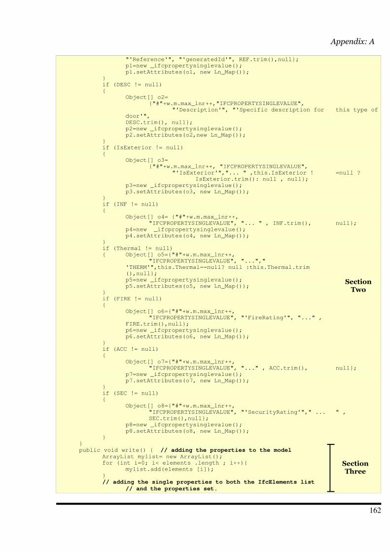
Appendix: A
"'Reference'", "'generatedId'", REF.trim(),null};
p1=new _ifcpropertysinglevalue();
p1.setAttributes(o1, new Ln_Map());
}
if (DESC != null)
{
Object[] o2=
{"#"+w.m.max_lnr++,"IFCPROPERTYSINGLEVALUE",
"'Description'", "'Specific description for this type of
door'",
DESC.trim(), null};
p2=new _ifcpropertysinglevalue();
p2.setAttributes(o2,new Ln_Map());
}
if (IsExterior != null)
{
Object[] o3=
{"#"+w.m.max_lnr++, "IFCPROPERTYSINGLEVALUE",
"'IsExterior'","... " ,this.IsExterior ! =null ?
IsExterior.trim(): null , null};
p3=new _ifcpropertysinglevalue();
p3.setAttributes(o3, new Ln_Map());
}
if (INF != null)
{
Object[] o4= {"#"+w.m.max_lnr++,
"IFCPROPERTYSINGLEVALUE", "... " , INF.trim(), null};
p4=new _ifcpropertysinglevalue();
p4.setAttributes(o4, new Ln_Map());
}
if (Thermal != null)
{ Object[] o5={"#"+w.m.max_lnr++,
"IFCPROPERTYSINGLEVALUE", "...","
'THERM'",this.Thermal==null? null :this.Thermal.trim
(),null};
p5=new _ifcpropertysinglevalue();
p5.setAttributes(o5, new Ln_Map());
}
if (FIRE != null)
{
Object[] o6={"#"+w.m.max_lnr++,
"IFCPROPERTYSINGLEVALUE", "'FireRating'", "..." ,
FIRE.trim(),null};
p6=new _ifcpropertysinglevalue();
p6.setAttributes(o6, new Ln_Map());
}
if (ACC != null)
{
Object[] o7={"#"+w.m.max_lnr++,
"IFCPROPERTYSINGLEVALUE", "..." , ACC.trim(), null};
p7=new _ifcpropertysinglevalue();
p7.setAttributes(o7, new Ln_Map());
}
if (SEC != null)
{
Object[] o8={"#"+w.m.max_lnr++,
"IFCPROPERTYSINGLEVALUE", "'SecurityRating'"," ... " ,
SEC.trim(),null};
p8=new _ifcpropertysinglevalue();
p8.setAttributes(o8, new Ln_Map());
}
}
public void write() { // adding the properties to the modelArrayList mylist= new ArrayList();
for (int i=0; i< elements .length ; i++){
mylist.add(elements [i]);
}
// adding the single properties to both the IfcElements list
// and the properties set.
162
SectionTwo
SectionThree
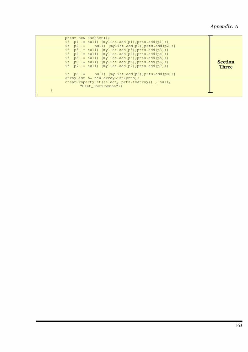
Appendix: A
prts= new HashSet();
if (p1 != null) {mylist.add(p1);prts.add(p1);}
if (p2 != null) {mylist.add(p2);prts.add(p2);}
if (p3 != null) {mylist.add(p3);prts.add(p3);}
if (p4 != null) {mylist.add(p4);prts.add(p4);}
if (p5 != null) {mylist.add(p5);prts.add(p5);}
if (p6 != null) {mylist.add(p6);prts.add(p6);}
if (p7 != null) {mylist.add(p7);prts.add(p7);}
if (p8 != null) {mylist.add(p8);prts.add(p8);}
ArrayList b= new ArrayList(prts);
creatPropertySet(select, prts.toArray() , null,
"Pset_DoorCommon");
}
}
163
SectionThree
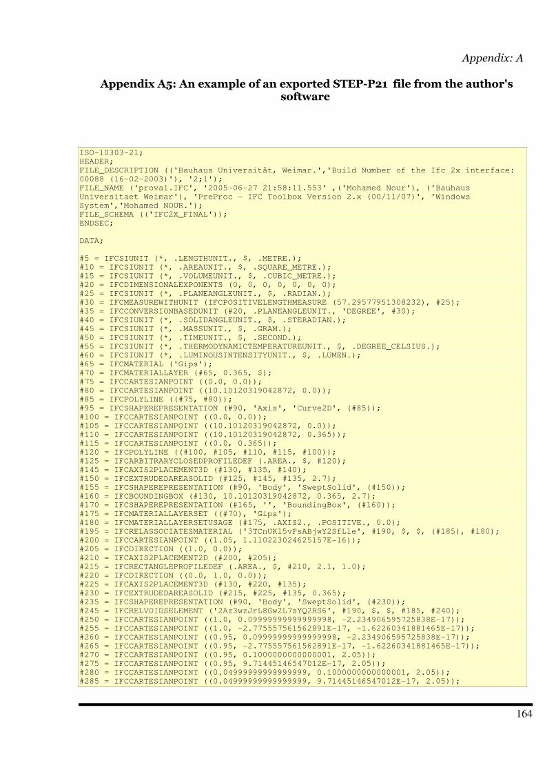
Appendix: A
Appendix A5: An example of an exported STEP-P21 file from the author'ssoftware
ISO-10303-21;
HEADER;
FILE_DESCRIPTION (('Bauhaus Universität, Weimar.','Build Number of the Ifc 2x interface:
00088 (16-02-2003)'), '2;1');
FILE_NAME ('prova1.IFC', '2005-06-27 21:58:11.553' ,('Mohamed Nour'), ('Bauhaus
Universitaet Weimar'), 'PreProc - IFC Toolbox Version 2.x (00/11/07)', 'Windows
System','Mohamed NOUR.');
FILE_SCHEMA (('IFC2X_FINAL'));
ENDSEC;
DATA;
#5 = IFCSIUNIT (*, .LENGTHUNIT., $, .METRE.);
#10 = IFCSIUNIT (*, .AREAUNIT., $, .SQUARE_METRE.);
#15 = IFCSIUNIT (*, .VOLUMEUNIT., $, .CUBIC_METRE.);
#20 = IFCDIMENSIONALEXPONENTS (0, 0, 0, 0, 0, 0, 0);
#25 = IFCSIUNIT (*, .PLANEANGLEUNIT., $, .RADIAN.);
#30 = IFCMEASUREWITHUNIT (IFCPOSITIVELENGTHMEASURE (57.29577951308232), #25);
#35 = IFCCONVERSIONBASEDUNIT (#20, .PLANEANGLEUNIT., 'DEGREE', #30);
#40 = IFCSIUNIT (*, .SOLIDANGLEUNIT., $, .STERADIAN.);
#45 = IFCSIUNIT (*, .MASSUNIT., $, .GRAM.);
#50 = IFCSIUNIT (*, .TIMEUNIT., $, .SECOND.);
#55 = IFCSIUNIT (*, .THERMODYNAMICTEMPERATUREUNIT., $, .DEGREE_CELSIUS.);
#60 = IFCSIUNIT (*, .LUMINOUSINTENSITYUNIT., $, .LUMEN.);
#65 = IFCMATERIAL ('Gips');
#70 = IFCMATERIALLAYER (#65, 0.365, $);
#75 = IFCCARTESIANPOINT ((0.0, 0.0));
#80 = IFCCARTESIANPOINT ((10.10120319042872, 0.0));
#85 = IFCPOLYLINE ((#75, #80));
#95 = IFCSHAPEREPRESENTATION (#90, 'Axis', 'Curve2D', (#85));
#100 = IFCCARTESIANPOINT ((0.0, 0.0));
#105 = IFCCARTESIANPOINT ((10.10120319042872, 0.0));
#110 = IFCCARTESIANPOINT ((10.10120319042872, 0.365));
#115 = IFCCARTESIANPOINT ((0.0, 0.365));
#120 = IFCPOLYLINE ((#100, #105, #110, #115, #100));
#125 = IFCARBITRARYCLOSEDPROFILEDEF (.AREA., $, #120);
#145 = IFCAXIS2PLACEMENT3D (#130, #135, #140);
#150 = IFCEXTRUDEDAREASOLID (#125, #145, #135, 2.7);
#155 = IFCSHAPEREPRESENTATION (#90, 'Body', 'SweptSolid', (#150));
#160 = IFCBOUNDINGBOX (#130, 10.10120319042872, 0.365, 2.7);
#170 = IFCSHAPEREPRESENTATION (#165, '', 'BoundingBox', (#160));
#175 = IFCMATERIALLAYERSET ((#70), 'Gips');
#180 = IFCMATERIALLAYERSETUSAGE (#175, .AXIS2., .POSITIVE., 0.0);
#195 = IFCRELASSOCIATESMATERIAL ('3TCnUKl5vFsABjwY2SfLle', #190, $, $, (#185), #180);
#200 = IFCCARTESIANPOINT ((1.05, 1.110223024625157E-16));
#205 = IFCDIRECTION ((1.0, 0.0));
#210 = IFCAXIS2PLACEMENT2D (#200, #205);
#215 = IFCRECTANGLEPROFILEDEF (.AREA., $, #210, 2.1, 1.0);
#220 = IFCDIRECTION ((0.0, 1.0, 0.0));
#225 = IFCAXIS2PLACEMENT3D (#130, #220, #135);
#230 = IFCEXTRUDEDAREASOLID (#215, #225, #135, 0.365);
#235 = IFCSHAPEREPRESENTATION (#90, 'Body', 'SweptSolid', (#230));
#245 = IFCRELVOIDSELEMENT ('2Az3wzJrL8Gw2L7sYQ2RS6', #190, $, $, #185, #240);
#250 = IFCCARTESIANPOINT ((1.0, 0.09999999999999998, -2.234906595725838E-17));
#255 = IFCCARTESIANPOINT ((1.0, -2.775557561562891E-17, -1.62260341881465E-17));
#260 = IFCCARTESIANPOINT ((0.95, 0.09999999999999998, -2.234906595725838E-17));
#265 = IFCCARTESIANPOINT ((0.95, -2.775557561562891E-17, -1.62260341881465E-17));
#270 = IFCCARTESIANPOINT ((0.95, 0.1000000000000001, 2.05));
#275 = IFCCARTESIANPOINT ((0.95, 9.71445146547012E-17, 2.05));
#280 = IFCCARTESIANPOINT ((0.04999999999999999, 0.1000000000000001, 2.05));
#285 = IFCCARTESIANPOINT ((0.04999999999999999, 9.71445146547012E-17, 2.05));
164
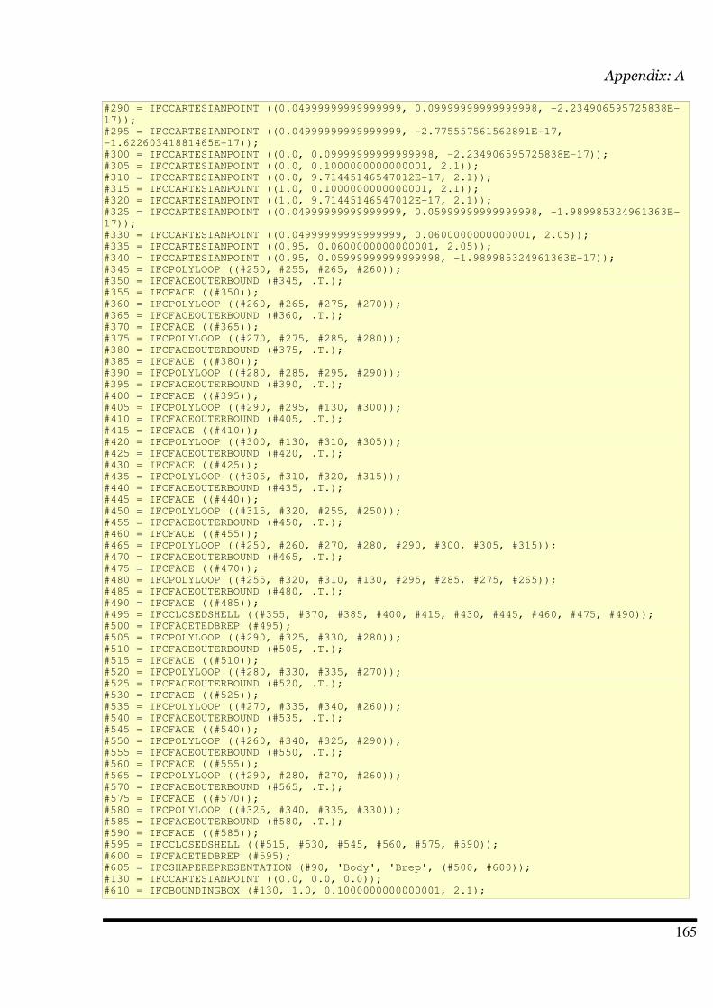
Appendix: A
#290 = IFCCARTESIANPOINT ((0.04999999999999999, 0.09999999999999998, -2.234906595725838E-
17));
#295 = IFCCARTESIANPOINT ((0.04999999999999999, -2.775557561562891E-17,
-1.62260341881465E-17));
#300 = IFCCARTESIANPOINT ((0.0, 0.09999999999999998, -2.234906595725838E-17));
#305 = IFCCARTESIANPOINT ((0.0, 0.1000000000000001, 2.1));
#310 = IFCCARTESIANPOINT ((0.0, 9.71445146547012E-17, 2.1));
#315 = IFCCARTESIANPOINT ((1.0, 0.1000000000000001, 2.1));
#320 = IFCCARTESIANPOINT ((1.0, 9.71445146547012E-17, 2.1));
#325 = IFCCARTESIANPOINT ((0.04999999999999999, 0.05999999999999998, -1.989985324961363E-
17));
#330 = IFCCARTESIANPOINT ((0.04999999999999999, 0.0600000000000001, 2.05));
#335 = IFCCARTESIANPOINT ((0.95, 0.0600000000000001, 2.05));
#340 = IFCCARTESIANPOINT ((0.95, 0.05999999999999998, -1.989985324961363E-17));
#345 = IFCPOLYLOOP ((#250, #255, #265, #260));
#350 = IFCFACEOUTERBOUND (#345, .T.);
#355 = IFCFACE ((#350));
#360 = IFCPOLYLOOP ((#260, #265, #275, #270));
#365 = IFCFACEOUTERBOUND (#360, .T.);
#370 = IFCFACE ((#365));
#375 = IFCPOLYLOOP ((#270, #275, #285, #280));
#380 = IFCFACEOUTERBOUND (#375, .T.);
#385 = IFCFACE ((#380));
#390 = IFCPOLYLOOP ((#280, #285, #295, #290));
#395 = IFCFACEOUTERBOUND (#390, .T.);
#400 = IFCFACE ((#395));
#405 = IFCPOLYLOOP ((#290, #295, #130, #300));
#410 = IFCFACEOUTERBOUND (#405, .T.);
#415 = IFCFACE ((#410));
#420 = IFCPOLYLOOP ((#300, #130, #310, #305));
#425 = IFCFACEOUTERBOUND (#420, .T.);
#430 = IFCFACE ((#425));
#435 = IFCPOLYLOOP ((#305, #310, #320, #315));
#440 = IFCFACEOUTERBOUND (#435, .T.);
#445 = IFCFACE ((#440));
#450 = IFCPOLYLOOP ((#315, #320, #255, #250));
#455 = IFCFACEOUTERBOUND (#450, .T.);
#460 = IFCFACE ((#455));
#465 = IFCPOLYLOOP ((#250, #260, #270, #280, #290, #300, #305, #315));
#470 = IFCFACEOUTERBOUND (#465, .T.);
#475 = IFCFACE ((#470));
#480 = IFCPOLYLOOP ((#255, #320, #310, #130, #295, #285, #275, #265));
#485 = IFCFACEOUTERBOUND (#480, .T.);
#490 = IFCFACE ((#485));
#495 = IFCCLOSEDSHELL ((#355, #370, #385, #400, #415, #430, #445, #460, #475, #490));
#500 = IFCFACETEDBREP (#495);
#505 = IFCPOLYLOOP ((#290, #325, #330, #280));
#510 = IFCFACEOUTERBOUND (#505, .T.);
#515 = IFCFACE ((#510));
#520 = IFCPOLYLOOP ((#280, #330, #335, #270));
#525 = IFCFACEOUTERBOUND (#520, .T.);
#530 = IFCFACE ((#525));
#535 = IFCPOLYLOOP ((#270, #335, #340, #260));
#540 = IFCFACEOUTERBOUND (#535, .T.);
#545 = IFCFACE ((#540));
#550 = IFCPOLYLOOP ((#260, #340, #325, #290));
#555 = IFCFACEOUTERBOUND (#550, .T.);
#560 = IFCFACE ((#555));
#565 = IFCPOLYLOOP ((#290, #280, #270, #260));
#570 = IFCFACEOUTERBOUND (#565, .T.);
#575 = IFCFACE ((#570));
#580 = IFCPOLYLOOP ((#325, #340, #335, #330));
#585 = IFCFACEOUTERBOUND (#580, .T.);
#590 = IFCFACE ((#585));
#595 = IFCCLOSEDSHELL ((#515, #530, #545, #560, #575, #590));
#600 = IFCFACETEDBREP (#595);
#605 = IFCSHAPEREPRESENTATION (#90, 'Body', 'Brep', (#500, #600));
#130 = IFCCARTESIANPOINT ((0.0, 0.0, 0.0));
#610 = IFCBOUNDINGBOX (#130, 1.0, 0.1000000000000001, 2.1);
165
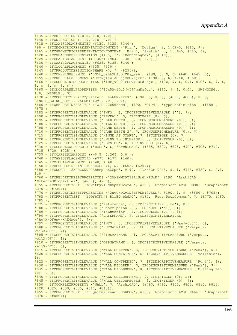
Appendix: A
#135 = IFCDIRECTION ((0.0, 0.0, 1.0));
#140 = IFCDIRECTION ((1.0, 0.0, 0.0));
#615 = IFCAXIS2PLACEMENT3D (#130, #135, #140);
#90 = IFCGEOMETRICREPRESENTATIONCONTEXT ('Plan', 'Design', 3, 1.0E-5, #615, $);
#165 = IFCGEOMETRICREPRESENTATIONCONTEXT ('Plan', 'Sketch', 3, 1.0E-5, #615, $);
#620 = IFCSHAPEREPRESENTATION (#165, '', 'BoundingBox', (#610));
#625 = IFCCARTESIANPOINT ((3.465191904287138, 0.0, 0.0));
#630 = IFCAXIS2PLACEMENT3D (#625, #135, #140);
#640 = IFCLOCALPLACEMENT (#635, #630);
#645 = IFCPRODUCTDEFINITIONSHAPE ($, $, (#235));
#240 = IFCOPENINGELEMENT ('0S5L_BYhL9HA$DiCBs_2sA', #190, $, $, $, #640, #645, $);
#655 = IFCRELFILLSELEMENT ('3mzNgIau1ASutjmkUxrjkk', #190, $, $, #240, #650);
#660 = IFCDOORLININGPROPERTIES ('1Dk_90R91FCPwTTDLdBFjz', #190, $, $, 0.1, 0.05, $, $, $,
$, $, $, $, $, $);
#665 = IFCDOORPANELPROPERTIES ('3Cx5MviDz3jvI97hgKs7dz', #190, $, $, 0.04, .SWINGING.,
1.0, .MIDDLE., $);
#670 = IFCDOORSTYLE ('22pPa5fu13r98s6EWYiKfX', #190, $, $, $, (#660, #665), $, $, .
SINGLE_SWING_LEFT., .ALUMINIUM., .F., .F.);
#680 = IFCRELDEFINESBYTYPE ('OIP_02e66cedd', #190, 'OIP4', 'type_definition', (#650),
#675);
#685 = IFCPROPERTYSINGLEVALUE ('INFO', $, IFCDESCRIPTIVEMEASURE (''), $);
#690 = IFCPROPERTYSINGLEVALUE ('REVEAL', $, IFCINTEGER (0), $);
#695 = IFCPROPERTYSINGLEVALUE ('HEAD DEPTH', $, IFCNUMERICMEASURE (0.), $);
#700 = IFCPROPERTYSINGLEVALUE ('SILL DEPTH', $, IFCNUMERICMEASURE (0.), $);
#705 = IFCPROPERTYSINGLEVALUE ('JAMB DEPTH', $, IFCNUMERICMEASURE (0.), $);
#710 = IFCPROPERTYSINGLEVALUE ('JAMB DEPTH 2', $, IFCNUMERICMEASURE (0.), $);
#715 = IFCPROPERTYSINGLEVALUE ('HINGE AT START', $, IFCINTEGER (0), $);
#720 = IFCPROPERTYSINGLEVALUE ('SWING TO INTERIOR', $, IFCINTEGER (0), $);
#725 = IFCPROPERTYSINGLEVALUE ('REFSIDE', $, IFCINTEGER (0), $);
#730 = IFCCOMPLEXPROPERTY ('DOOR', $, 'ArchiCAD', (#685, #690, #695, #700, #705, #710,
#715, #720, #725));
#735 = IFCCARTESIANPOINT ((-0.5, 0.265, 0.0));
#740 = IFCAXIS2PLACEMENT3D (#735, #135, #140);
#745 = IFCLOCALPLACEMENT (#640, #740);
#750 = IFCPRODUCTDEFINITIONSHAPE ($, $, (#605, #620));
#650 = IFCDOOR ('2XRBG6KUPCABBepxeXZZpe', #190, 'T\X\FCr-004', $, $, #745, #750, $, 2.1,
1.0);
#760 = IFCRELDEFINESBYPROPERTIES ('2MA2MMI9T71RiUrdhxEUpK', #190, 'ArchiCAD',
'ExtendedProperties', (#650), #755);
#755 = IFCPROPERTYSET ('3OwdtkyV10dBOpKTH2ofe8', #190, 'Graphisoft AC70 DOOR', 'Graphisoft
AC70', (#730));
#770 = IFCRELDEFINESBYPROPERTIES ('3uvUkwGvLD5B69Kb12VESL', #190, $, $, (#650), #765);
#765 = IFCPROPERTYSET ('15OYbYFhj8_R1rBQ_bAdAQ', #190, 'Pset_DoorCommon', $, (#775, #780,
#785));
#775 = IFCPROPERTYSINGLEVALUE ('Reference', $, IFCIDENTIFIER ('re'), $);
#780 = IFCPROPERTYSINGLEVALUE ('Description', $, IFCLABEL ('d'), $);
#785 = IFCPROPERTYSINGLEVALUE ('IsExterior', $, IFCBOOLEAN (.T.), $);
#790 = IFCPROPERTYSINGLEVALUE ('LAYERNAME', $, IFCDESCRIPTIVEMEASURE
('Au\X\DFenw\X\E4nde'), $);
#795 = IFCPROPERTYSINGLEVALUE ('INFO', $, IFCDESCRIPTIVEMEASURE ('Wand-006'), $);
#800 = IFCPROPERTYSINGLEVALUE ('REFMATNAME', $, IFCDESCRIPTIVEMEASURE ('Verputz,
wei\X\DF'), $);
#805 = IFCPROPERTYSINGLEVALUE ('SIDEMATNAME', $, IFCDESCRIPTIVEMEASURE ('Verputz,
wei\X\DF'), $);
#810 = IFCPROPERTYSINGLEVALUE ('OPPMATNAME', $, IFCDESCRIPTIVEMEASURE ('Verputz,
wei\X\DF'), $);
#815 = IFCPROPERTYSINGLEVALUE ('WALL CONTPEN', $, IFCDESCRIPTIVEMEASURE ('Pen4'), $);
#820 = IFCPROPERTYSINGLEVALUE ('WALL CONTLTYPE', $, IFCDESCRIPTIVEMEASURE ('Vollinie'),
$);
#825 = IFCPROPERTYSINGLEVALUE ('WALL CONTPEN3D', $, IFCDESCRIPTIVEMEASURE ('Pen2'), $);
#830 = IFCPROPERTYSINGLEVALUE ('WALL FILLPEN', $, IFCDESCRIPTIVEMEASURE ('Pen2'), $);
#835 = IFCPROPERTYSINGLEVALUE ('WALL FILLBGPEN', $, IFCDESCRIPTIVEMEASURE ('Missing Pen
(0)'), $);
#840 = IFCPROPERTYSINGLEVALUE ('WALL USECOMPPENS', $, IFCINTEGER (0), $);
#845 = IFCPROPERTYSINGLEVALUE ('WALL USECOMPBGPEN', $, IFCINTEGER (0), $);
#850 = IFCCOMPLEXPROPERTY ('WALL', $, 'ArchiCAD', (#790, #795, #800, #805, #810, #815,
#820, #825, #830, #835, #840, #845));
#855 = IFCPROPERTYSET ('2uuQAfrmz0veWuL3Hm$CCN', #190, 'Graphisoft AC70 WALL', 'Graphisoft
AC70', (#850));
166
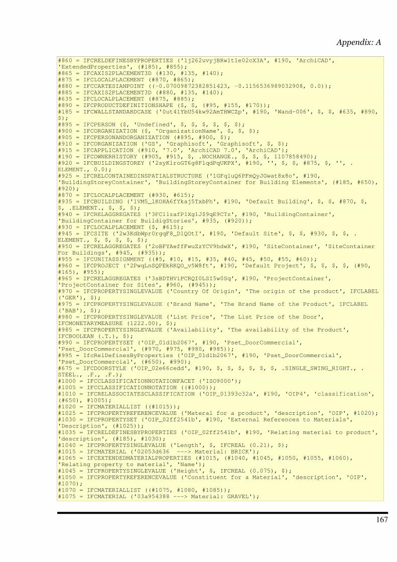
Appendix: A
#860 = IFCRELDEFINESBYPROPERTIES ('1j262uvyjBRw1t1e02cX3A', #190, 'ArchiCAD',
'ExtendedProperties', (#185), #855);
#865 = IFCAXIS2PLACEMENT3D (#130, #135, #140);
#875 = IFCLOCALPLACEMENT (#870, #865);
#880 = IFCCARTESIANPOINT ((-0.07009872382851423, -0.1156536989032908, 0.0));
#885 = IFCAXIS2PLACEMENT3D (#880, #135, #140);
#635 = IFCLOCALPLACEMENT (#875, #885);
#890 = IFCPRODUCTDEFINITIONSHAPE ($, $, (#95, #155, #170));
#185 = IFCWALLSTANDARDCASE ('0ut41YbU54kw92AmTHWCZp', #190, 'Wand-006', $, $, #635, #890,
$);
#895 = IFCPERSON ($, 'Undefined', $, $, $, $, $, $);
#900 = IFCORGANIZATION ($, 'OrganizationName', $, $, $);
#905 = IFCPERSONANDORGANIZATION (#895, #900, $);
#910 = IFCORGANIZATION ('GS', 'Graphisoft', 'Graphisoft', $, $);
#915 = IFCAPPLICATION (#910, '7.0', 'ArchiCAD 7.0', 'ArchiCAD');
#190 = IFCOWNERHISTORY (#905, #915, $, .NOCHANGE., $, $, $, 1107858490);
#920 = IFCBUILDINGSTOREY ('2syKlroGT6g8FlqdPqUKPX', #190, '', $, $, #875, $, '', .
ELEMENT., 0.0);
#925 = IFCRELCONTAINEDINSPATIALSTRUCTURE ('1GFqluQ6PFmQyJGwat8x8o', #190,
'BuildingStoreyContainer', 'BuildingStoreyContainer for Building Elements', (#185, #650),
#920);
#870 = IFCLOCALPLACEMENT (#930, #615);
#935 = IFCBUILDING ('1VM5_lKOHA6fYkaj5TxbPh', #190, 'Default Building', $, $, #870, $,
$, .ELEMENT., $, $, $);
#940 = IFCRELAGGREGATES ('3FCllzafP1Xg1J$9qE9CTz', #190, 'BuildingContainer',
'BuildingContainer for BuildigStories', #935, (#920));
#930 = IFCLOCALPLACEMENT ($, #615);
#945 = IFCSITE ('2w3KdbWpr0rgqF8_D1QOtI', #190, 'Default Site', $, $, #930, $, $, .
ELEMENT., $, $, $, $, $);
#950 = IFCRELAGGREGATES ('2oBFYAeffFwuZzYCV9hdwX', #190, 'SiteContainer', 'SiteContainer
For Buildings', #945, (#935));
#955 = IFCUNITASSIGNMENT ((#5, #10, #15, #35, #40, #45, #50, #55, #60));
#960 = IFCPROJECT ('2PwqLnSQPEkRKQO_v5W8ft', #190, 'Default Project', $, $, $, $, (#90,
#165), #955);
#965 = IFCRELAGGREGATES ('3sBDTHViPCRQI0LSI5w0Sq', #190, 'ProjectContainer',
'ProjectContainer for Sites', #960, (#945));
#970 = IFCPROPERTYSINGLEVALUE ('Country Of Origin', 'The origin of the product', IFCLABEL
('GER'), $);
#975 = IFCPROPERTYSINGLEVALUE ('Brand Name', 'The Brand Name of the Product', IFCLABEL
('BAB'), $);
#980 = IFCPROPERTYSINGLEVALUE ('List Price', 'The List Price of the Door',
IFCMONETARYMEASURE (1222.00), $);
#985 = IFCPROPERTYSINGLEVALUE ('Availability', 'The availability of the Product',
IFCBOOLEAN (.T.), $);
#990 = IFCPROPERTYSET ('OIP_01d1b2067', #190, 'Pset_DoorCommercial',
'Pset_DoorCommercial', (#970, #975, #980, #985));
#995 = IfcRelDefinesByProperties ('OIP_01d1b2067', #190, 'Pset_DoorCommercial',
'Pset_DoorCommercial', (#650), #990);
#675 = IFCDOORSTYLE ('OIP_02e66cedd', #190, $, $, $, $, $, $, .SINGLE_SWING_RIGHT., .
STEEL., .F., .F.);
#1000 = IFCCLASSIFICATIONNOTATIONFACET ('ISO9000');
#1005 = IFCCLASSIFICATIONNOTATION ((#1000));
#1010 = IFCRELASSOCIATESCLASSIFICATION ('OIP_01393c32a', #190, 'OIP4', 'classification',
(#650), #1005);
#1020 = IFCMATERIALLIST ((#1015));
#1025 = IFCPROPERTYREFERENCEVALUE ('Materal for a product', 'description', 'OIP', #1020);
#1030 = IFCPROPERTYSET ('OIP_02ff2541b', #190, 'External References to Materials',
'Description', (#1025));
#1035 = IFCRELDEFINESBYPROPERTIES ('OIP_02ff2541b', #190, 'Relating material to product',
'description', (#185), #1030);
#1040 = IFCPROPERTYSINGLEVALUE ('Length', $, IFCREAL (0.21), $);
#1015 = IFCMATERIAL ('02053d636 ---> Material: BRICK');
#1065 = IFCEXTENDEDMATERIALPROPERTIES (#1015, (#1040, #1045, #1050, #1055, #1060),
'Relating property to material', 'Name');
#1045 = IFCPROPERTYSINGLEVALUE ('Height', $, IFCREAL (0.075), $);
#1050 = IFCPROPERTYREFERENCEVALUE ('Constituent for a Material', 'description', 'OIP',
#1070);
#1070 = IFCMATERIALLIST ((#1075, #1080, #1085));
#1075 = IFCMATERIAL ('03a954388 ---> Material: GRAVEL');
167

Appendix: A
#1080 = IFCMATERIAL ('02f4c5ce9 ---> Material: SAND');
#1055 = IFCPROPERTYSINGLEVALUE ('Density', $, IFCREAL (1500), $);
#1060 = IFCPROPERTYSINGLEVALUE ('width', $, IFCREAL (0.15), $);
#1090 = IFCPROPERTYSINGLEVALUE ('Density', $, IFCREAL (1.3), $);
#1085 = IFCMATERIAL ('039f04613 ---> Material: SAND');
#1095 = IFCEXTENDEDMATERIALPROPERTIES (#1085, (#1090), 'Relating property to material',
'Name');
#1100 = IFCCLASSIFICATIONNOTATIONFACET ('ISO10000');
#1105 = IFCCLASSIFICATIONNOTATION ((#1100));
#1110 = IFCMATERIALCLASSIFICATIONRELATIONSHIP ((#1105), #1085);
ENDSEC;
END-ISO-10303-21;
168
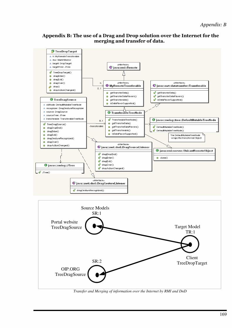
Appendix: B
Appendix B: The use of a Drag and Drop solution over the Internet for themerging and transfer of data.
169
Transfer and Merging of information over the Internet by RMI and DnD
Portal websiteTreeDragSource
SR:2Client
TreeDropTarget
Source ModelsSR:1
OIP.ORGTreeDragSource
Target ModelTR:1
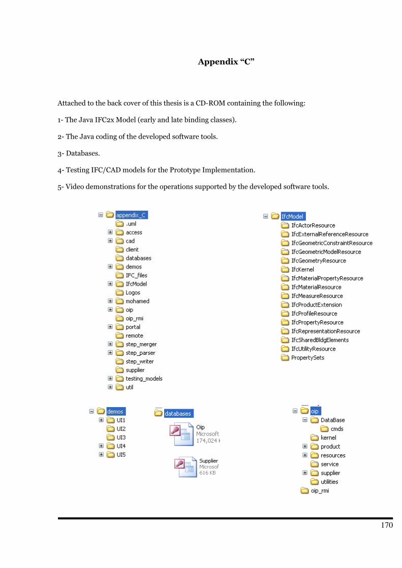
Appendix “C”
Attached to the back cover of this thesis is a CD-ROM containing the following:
1- The Java IFC2x Model (early and late binding classes).
2- The Java coding of the developed software tools.
3- Databases.
4- Testing IFC/CAD models for the Prototype Implementation.
5- Video demonstrations for the operations supported by the developed software tools.
170
Zusammenfassung
Die vorliegende Dissertation stellt ein flexibles und dynamisches Gebäudeinformationsmodell vor, mitdem die Produktinformationen der Bauteile erfragt und aktualisiert werden können. Dazu werdenBeziehungen zwischen den Bauteilen im Gebäudeinformationsmodell und den Produktinformationen derHersteller und Lieferanten definiert. Die Produktinformationen können über eindeutige Produktnamenund über verallgemeinerte Produktparameter identifiziert werden.
Der Stand der Technik bei den digitalen Bauteilkatalogen besteht überwiegend in einer Beschreibung derProdukte in Dokumenten im HTML- oder PDF-Format. Diese Dokumente können mit Hilfe vonSchlüsselwörtern durchsucht werden. Hierbei besteht das Problem, dass die Produktinformationen nichtdauerhaft den Objekten im Gebäudeinformationsmodell zuzuordnen sind. Demzufolge kann verfügbareCAD-Software die verwendeten Produkte der Bauteile nicht vollständig beschreiben. Da viele Prozesseaktuelle Informationen der Bauteilprodukte benötigen, ist eine Erweiterung vorhandenerGebäudeinformationsmodelle um diesen Aspekt erforderlich. Obwohl dies Gegenstand zahlreicherproprietärer Entwicklungen ist, ist der Austausch von Daten infolge fehlender Standardisierung nichtohne Informationsverluste möglich. Diesem Thema widmen sich derzeit unabhängigeForschungsprojekte, in denen neue Taxonomien und Ontologien für die Beschreibung der Semantik vonBauteildaten auf Basis von XML entwickelt werden. Diese Lösungsansätze haben den Nachteil, dass dieProduktinformationen der Hersteller und Lieferanten notwendigerweise in einer gemeinsamenDatenbasis gespeichert werden müssen.
Die Untersuchung des Lebenszyklus von Bauwerken im Hinblick auf die Wertschöpfungskette und dieBeschaffungskette ergab, dass die Informationen sowohl der Bauteile als auch der Produkte über diegesamte Lebensdauer des Bauwerks verfügbar sein müssen. Aus kaufmännischer Sicht besteht dasProblem, dass die Produkte eines Herstellers unter verschiedenen Markennamen angeboten und verkauftwerden. Untersuchungen haben gezeigt, dass der Markenname ein wesentlicher Faktor einerMarktstrategie ist. Auch die Zwischenhändler spielen hierbei eine wichtige Rolle – selbst dann, wenn dieGeschäfte über das Internet abgewickelt werden. Bauteile haben die Besonderheit, dass sie teilweise oderganz auf der Baustelle hergestellt werden. Dies muss bei der Konzeption eines Informationssystems, dassich mit der Wertschöpfungskette von Bauwerken befasst, beachtet werden.
Eine Erkenntnis der vorliegenden Arbeit ist, dass eine parametrisierte Produktsuche nur möglich ist,wenn die Produkte eindeutige Namen und standardisierte Parameter besitzen. Dieser Lösungsansatzkönnte die derzeitige Arbeitsweise in der Praxis ändern. Für die prototypische Umsetzung im Rahmen derDissertation hat sich eine Abstützung auf das verfügbare IFC-Modell als besonders geeignet erwiesen, dadieses Modell nicht-proprietär, fachübergreifend sowie durch Eigenschaften erweiterbar ist.
Der Kerngedanke des vorgestellten Lösungskonzepts besteht in der Entwicklung des OIP-Konzepts(Object Information Pack), welches eine dauerhafte und dynamische Datenquelle fürGebäudeinformationsmodelle behandelt. Die OIP ist nicht nur ein eindeutiger Produktname, sondern eineganze Datenstruktur für Produktinformationen im Bauwesen. Die OIP besteht aus einer dreischichtigenHierarchie, welche sich sowohl in der Struktur der Datenbasis als auch in der Struktur der Klassenwiderspiegelt. Diese Struktur wird über eine Gruppe von Relationen vom OIP-Kern verwaltet. Das Formatder OIP-Namen sowie die Verteilung der Daten zwischen den Beteiligten (produktunabhängige technischeDaten und produktabhängige Daten der Lieferanten) sind die wesentlichen Neuerungen gegenüber denbekannten Ansätzen mit einer zentralen Datenbasis. Das in dieser Arbeit vorgestellte Lösungskonzeptbasiert auf einer eingehenden Betrachtung und Analyse der Beschaffungskette von Bauwerken unterBeachtung der Besonderheiten des Bauwesens.
171

Es hat sich herausgestellt, dass das OIP-Konzept allein nicht ausreicht, um eine Brücke zwischen denDaten der Hersteller und Händler auf der einen und dem Kunden auf der anderen Seite zu schlagen.Darüber hinaus wurde eine integrierte Softwarelösung für die Umsetzung des Konzepts benötigt, die zumZeitpunkt des Entstehens dieser Dissertation nicht verfügbar war. Daher hat der Autor Werkzeuge mitfolgender Funktionalität entwickelt:
Parsen von STEP-ISO-10303-P21-Dateien
Interpretation der geparsten Daten in IFC2x-Java-Klassen
Abbildung und Integration von Produktdaten in das IFC-Modell
Instanziierung, Löschen und Änderung von Objekten
Definition von Suchparametern durch den Anwender
Extraktion von Suchparametern aus dem CAD/IFC-Model
Durchführen von parametrisierten Suchen
Bereitstellung verschiedener Arten der Visualisierung des IFC Modells
Export des modifizierten IFC-Modells in Form einer STEP-P21-Datei
Mit diesen Werkzeugen konnte das Konzept der Arbeit verifiziert werden. Aufgrund ihres flexiblenEntwurfs können diese Werkzeuge darüber hinaus auch bei anderen Problemstellungen imZusammenhang mit dem IFC-Modell verwendet werden. Es handelt sich nämlich um einfache Werkzeuge,die eine Integration des IFC-Modells in andere Applikationen ermöglichen.
Die Einführung des Konzepts in die Praxis erfordert die Verwaltung durch eine eigene Organisation. DieRolle dieser OIP-Organisation und das Internetportal der Hersteller wurden ebenfalls innerhalb einerverteilten Applikation simuliert. Zur übersichtlichen Darstellung der Ergebnisse und zum Nachweis derAnwendbarkeit des Konzeptes wurden alle Werkzeuge mit einer graphischen Nutzeroberflächenausgestattet.
Schließlich möchte der Autor betonen, dass eine Übernahme eines solchen „Business Process Re-engeneering“ (BPR) Konzeptes in die industrielle Praxis nicht frei von Barrieren und Problemen ist. Ausder Literatur über Firmenkultur und Psychologie ist bekannt, dass Nutzer oft ablehnend auf dieEinführung neuer Systeme reagieren, wenn diese die gewohnte Arbeitsweise in Frage stellen. Hierbeispielt es keine Rolle, ob das resultierende Ergebnis auf lange Sicht zu einer Optimierung und Reduzierungdes Aufwands führt. Ein Wechsel der derzeitigen Praxis könnte jedoch erreicht werden, wenn einigeinnovative Unternehmen ihren Anwendern die Gelegenheit gäben, sich von den Vorteilen der neuenArbeitsweise zu überzeugen.
172


![REICH, Wihelm. a Irrupcao Da Moral Sexual Repressiva[1]](https://img.pdfslide.net/doc/110x75/557202064979599169a2d165/reich-wihelm-a-irrupcao-da-moral-sexual-repressiva1.jpg)