Embed Size (px)
Citation preview

CONSTRUCTION MANAGEMENT PLAN
CONSTRUCTION MANAGEMENT SERVICES FOR LAYON LANDFILL SYSTEMS,
ENTRANCE FACILITIES, ACCESS ROAD, SEWER SYSTEM, AND UTILITIES
PROJECT NO. RECEIVER-SW-09-03
LAYON, INARAJAN, GUAM
FOR THE SOLID WASTE MANAGEMENT DIVISION GOVERNMENT OF GUAM
JANUARY, 25, 2010
Prepared by
194 Hernan Cortez Avenue Suite 213 Hagatna, Guam 96910
Case 1:02-cv-00022 Document 557-3 Filed 04/08/10 Page 1 of 139

WINZLER & KELLY CONSULTING ENGINEERS
I-2
SECTION I – INTRODUCTION A. Purpose and Goals ……………………………………………………………………... 1B. Project Descriptions …………………………………………………………………… 1C. Schedule ………………………………………………………………………………… 1D. Budget …………………………………………………………………………………... 2E. Warranty Periods ……………………………………………………………………… 2 SECTION II – PROJECT TEAM AND ORGANIZATION A. Organizational Structure/Chain of Command ………………………………………... 3B. Duties and Responsibilities …………………………………………………………… 4 SECTION III – CONSTRUCTION CONTRACT ADMINISTRATION A. General ……………………………………………………………………..................... 15B. Communications with Contractors ...………………………………………………… 15C. Communications with Engineer ……………………………………………………… 17D. Communications with Agencies, Local Residents and Businesses ………..………... 17E. Meetings ………...……………………………………………………………………… 18F. Construction Schedule ………………………………………………………………… 19G. Progress Payments …………………………………………………………………….. 21H. Submittals ……………………………………………………………………………… 22I. Requests for Information (RFI) ……………………………………………………… 24J. Materials Testing and Quality Control ………………………………………………. 25K. Change Orders ………………………………………………………………………… 25L. Claims ………………………………………………………………………………….. 26M. Forms ………………………………………………………………………………….. 27 SECTION IV – FIELD OFFICE ADMINISTRATION A. General ……………………………………………………………………..................... 28B. Meetings ………...……………………………………………………………………… 28C. Submittal and RFI Files and Routing ...……………………………………………… 28D. Document Processing and Distribution ……………………………………..………... 28E. Correspondence Filing System ...……………………………………………………… 28F. Project File Turnover to Owner ....…………………………………………………… 29 SECTION V - FIELD DOCUMENTATION A. Documentation of Work Progress ………………………………………..................... 30B. Surveying/Layout ……………………………………………………………………… 31C. Material Testing ……………………......……………………………………………… 32D. Jobsite Inspection ……………………...……………………………………..………... 33E. Record Drawings …………….....……………………………………………………… 33F. Permits and Related Requirements ...………………………………………………… 34
SECTION VI – HOME OFFICE ADMINISTRATION A. Home Office Services …………….………………………………………..................... 35
Case 1:02-cv-00022 Document 557-3 Filed 04/08/10 Page 2 of 139

WINZLER & KELLY CONSULTING ENGINEERS
I-3
B. Meetings ………...……………………………………………………………………… 35C. Files and Request Routing …………......……………………………………………… 35D. Document Processing and Distribution ……………………………………..………... 35E. Filing System ……...………….....……………………………………………………… 36F. Project File Turnover to Owner …....………………………………………………… 36 SECTION VII – DOCUMENT REVIEW A. Contract …………….…………….………………………………………..................... 37B. Inspection Requirements ……………………………………………………………… 37C. Safety and Loss Prevention ..………......……………………………………………… 37 SECTION VIII – EMERGENCY SERVICES A. Emergency Services ...…………….………………………………………..................... 38 SECTION IX – PUBLIC NOTICES AND COMMUNITY RELATIONS A. General …..………….…………….………………………………………..................... 39B. Public Notices ……………...…………………………………………………………… 39C. Community Relations ..………….…......……………………………………………… 39 SECTION X- FINAL INSPECTION AND CLOSE-OUT A. Introduction ………………………………………………………………..................... 40B. Record Drawings.……………………………………………………………………… 40C. Final Payment ………………………………..………………………………………… 40D. Warranty ……………………………….……………………………………..………... 41E. Final Acceptance …………….....……………………………………………………… 41
Case 1:02-cv-00022 Document 557-3 Filed 04/08/10 Page 3 of 139

1 WINZLER & KELLY
CM Plan for Layon Landfill
SECTION I - INTRODUCTION A. Purpose and Goals
This Construction Management Plan (CM Plan) sets forth the procedures and approach for the construction of the Entrance Area Facilities, Liners for Landfill Cells 1 and 2 (Project No. SWMD-09-02); and, Access Road and Sewer System (Project No. SWMD-09-03). The goal of the CM Plan is to obtain a successful project. The definition of a successful project is safe construction of quality facilities on schedule, and within the budget.
The CM Plan will serve Winzler & Kelly (W&K), the Owner’s Representatives, and Contractors by defining the project, project team members and their roles, coordination among team members, procedures, and key milestones and schedule constraints. By establishing these parameters early in the project, the CM Plan will help control resources and costs, and establish communication and coordination between W&K, the Designers (TG Engineers as the Prime Consultants and A-Mehr, Inc. for Landfill Design), and the Contractors (Black Construction Corp. for Landfill Construction and Core Tech International for the Access Road, Sewer System, and Utilities Construction).
B. Project Descriptions
SWMD-09-02 Entrance Area Facilities and Cells 1 & 2 The landfill (“Project”) involves the erection of facilities within the entrance area of the landfill site, installation of liners for Cells 1 and 2, and construction of the operations road, sewer system, and utilities within the site. The scope of work includes, but is not limited to, removal of existing roadbed and sub-grade where such occurs; clearing and grubbing; mass grading (cut and fill); utility relocation and extensions; construction of two-lane asphalt concrete roadway with shoulders, drainage facilities, guardrails, street lighting, signing and striping; construction of water, sewer and power utilities; installation of the liner system; and other related work as necessary to make the Project complete and ready to use. SWMD-09-03 Access Road and Sewer System The work is limited to the proposed roadway construction and reconstruction from Route 4 to the New Layon Municipal Sanitary Landfill; sewer force main and pump stations from the landfill site down Route 4 to Inarajan; gravity sewer piping system; water main and joint utility trench from near Route 4 to the New Layon Municipal Sanitary Landfill; overhead electric power lines; and other related work as necessary to make the Project complete and ready to use.
C. Schedule
The Notice to Proceed (NTP), project lengths and initial contract deadlines for the two projects comprising the Project are as follows:
Case 1:02-cv-00022 Document 557-3 Filed 04/08/10 Page 4 of 139

2 WINZLER & KELLY
CM Plan for Layon Landfill
BLACK CONSTRUCTION CORP.: ENTRANCE AREA AND CELLS 1 AND 2: NTP DATE: 12/30/09 CONTRACT LENGTH (CALENDAR DAYS): 500 CONTRACT COMPLETION DATE: 5/14/11 CORE TECH INTERNATIONAL, ACCESS ROAD AND SEWER SYSTEM: NTP DATE: 12/14/09 CONTRACT LENGTH (CALENDAR DAYS): 500 CONTRACT COMPLETION DATE: 4/27/11
These projects are unique in that they are managed under the control of the U.S. District Court - appointed receiver, Gershman, Brickner and Bratton, and must be completed before the Ordot Dump can be closed as required by the U.S. District Court. The contractors acknowledge that failure to complete the projects within the time provided in the contracts could be detrimental to the island and Government of Guam and may result in significant penalties from the U.S. District Court to the Government of Guam and even worse, it could leave the island with no location to dispose of trash which could be catastrophic. If the contractor fails to complete the work within the time prescribed herein, they will be responsible to cover any losses or damages that the Government of Guam may have incurred through the (Liquidated Damages) LD clauses in the contract. The LD clauses for both projects set forth in their respective contracts, are as follows: BLACK CONSTRUCTION CORP.: ENTRANCE AREA AND CELLS 1 AND 2: LIQUIDATED DAMAGE CLAUSE AMOUNT $3,300/Day CORE TECH INTERNATIONAL, ACCESS ROAD AND SEWER SYSTEM: LIQUIDATED DAMAGE CLAUSE AMOUNT $3,300/Day D. Budget The construction contracts and initial budgets for both projects are as follows: BLACK CONSTRUCTION CORP.: ENTRANCE AREA AND CELLS 1 AND 2: INITIAL CONTRACT AMOUNT $20,477,000.00 CORE TECH INTERNATIONAL, ACCESS ROAD & SEWER SYSTEM: INITIAL CONTRACT AMOUNT $26,800,000.00 The contractors are to submit a Schedule of Values (SOV) that provides a detailed breakdown for the lump sum costs in their contracts for the purpose of determining percentage of work complete for partial pay requests. It is important to note that the SOV quantities will be developed by the contractors for the purpose of estimating percent complete for the partial payments and not for determining the contractual quantities. In the event that it is determined a contractor’s quantity estimate was inaccurate then the unit cost used for partial pay estimates will be adjusted appropriately and no change in the lump sum cost will occur. Any credit or deduct required to adjust the partial payment with the correct percent complete will take place on the next Pay Request. E. Warranty Periods: The contract warranty periods are one year from final acceptance except for various items that are subject to longer manufacturer warranties.
Case 1:02-cv-00022 Document 557-3 Filed 04/08/10 Page 5 of 139

3 WINZLER & KELLY
CM Plan for Layon Landfill
SECTION II - PROJECT TEAM AND ORGANIZATION A. Organizational Structure/Chain of Command
Winzler & Kelly has teamed with Vector Engineering and contracted with the Government of Guam through the Receiver Gershman, Brickner & Bratton (GBB) for the projects. The members of the CM team from Winzler & Kelly consist of one Principal-in-Charge, Construction Manager (CM), Construction Management Quality Assurance/Control Manager (CMQM), one Health and Safety Manager (HSM), one Administrative Assistant, one full-time Project Engineer, multiple part- time Project Engineers, one full-time inspector, multiple part-time inspectors and additional support staff. The members of the CM team from Vector Engineering consist of one Principal-in-Charge, one Quality Assurance Engineer (QAE), one Liner Construction Manager (LCM), and two Liner Inspectors. Figure 1 shows the proposed Organizational Chart for the CM and Project Teams. The Project Team includes all the primary stakeholders in the Project such as the Receiver, regulatory and utility agencies, the contractors and CM. The upper portion of the Organizational Chart contains the key personnel for the CM Team and the lower portion of the chart shows the supporting staff. One important point is that the CM team includes two Construction Managers; the overall Construction Manager (CM), Paul Baron, of W&K; and a Liner Construction Manager (LCM), Jose Armenta, C.E.T. from Vector Engineering. The CM and LCM are supported by two key Principals: Fred Smith of W&K and Scott Purdy of Vector. In addition, Bryan Fritzler, the Liner Quality Assurance Engineer (Vector) and Jarrett Brown the Construction Quality Assurance/Quality Control Manager (W&K). The CM will manage all non-liner related construction as well as Storm Water Pollution Prevention Plan and environmental compliance, regulatory and utility agency coordination, safety, coordination between contractors, dispute resolution, and coordination among the multiple projects. The LCM will manage the liner construction and provide support to the CM as needed for other Project issues. In addition to the above, the organizational chart shows some personnel with dual or multiple roles that crossover between key roles and support roles. Also, the contractor’s Management and QA/QC Teams are integrated into the chart interfacing between the CM key personnel and the support staff; and the Receiver team has direct access to the Principals and Construction Managers.
Case 1:02-cv-00022 Document 557-3 Filed 04/08/10 Page 6 of 139

4 WINZLER & KELLY
CM Plan for Layon Landfill
B. Duties and Responsibilities
General position descriptions and basic duties and responsibilities regarding construction quality assurance for the “Landfill Liner Systems” are identified in the landfill project specifications Section 01400A and attached in Appendix A. The descriptions and roles provided in Section 01400A form the basis for the Duties and Responsibilities described in the following paragraphs for the CM Team. However, they have been clarified to address the overall project structure for both projects and not just the landfill liner systems. Appendix B is a list of all key Project personnel including, name, title, project position (in accordance with Spec Section 1400A) and contact information known at the time of preparation. This is a working document and shall be updated periodically throughout the Project. Names, titles, position descriptions and basic duties and responsibilities for the main Project team members are as follows:
1. Paul K. Baron, P.E. Construction Manager (CM)
The CM is an official representative of the Receiver and is the equivalent of the “Project Manager” listed in Section 01400A of the landfill project specifications. The CM coordinates construction and quality assurance activities: field observation for CM Team, communications, meetings, staffing for the CM Team; coordinating resolution of quality assurance issues; and coordination with local property owners, Inarajan Mayor, regulatory and utility agencies. The CM is the primary contact for incoming and outgoing Project
Case 1:02-cv-00022 Document 557-3 Filed 04/08/10 Page 7 of 139

5 WINZLER & KELLY
CM Plan for Layon Landfill
communications and management of the field office, daily construction engineering, and inspection and testing activities. The CM serves as a day-to-day contact with the contractors’ construction superintendents, the Owner’s Representative (GBB), the Design A/E, and is the primary liaison for the Project. Specific task assignments include:
o Implements the requirements of the Contract Documents and reviews plans and specifications with Contractor;
o Reviews and recommends contractor pay requests and contractor payroll; o Coordinates contact with government agencies and potential visitors to the Project
Site; o Assigns incoming correspondence to appropriate staff for response. Reviews and
signs outgoing correspondence; o Conducts preconstruction meetings; o Prepares for and conducts weekly progress meetings; o Oversees of Project files and documentation; o Reviews Change Order Requests (COR) and proposes contract change orders; o Develops COR and assigns to staff for analysis; o Reviews, analyzes and negotiates claim issues and disputes; o Reviews and monitors construction schedule and monthly updates and schedule of
shop drawings and schedule of values prepared by contractors; o Prepares weekly status updates; o Arranges and conducts Project meetings and reviews and approves minutes for
circulation; o Reviews contractor progress payment requests and approves appropriate payment
amounts based on work completed; o Coordinates submittal, Design Clarifications (DC) and Requests For Information
(RFI) review and processing; o Reviews and ensures that record drawings are kept current by contractors; o Coordinates observation and testing activities; assures appropriate personnel are
onsite. Performs periodic observation and observation of critical elements as necessary;
o Conducts final inspections and recommends final acceptance. o Defers technical and QA decisions for work within or connected to Cells 1 and 2 and
liner related issues to the Liner Construction Manager (LCM) and Quality Assurance Engineer (QAE);
o Monitors regulatory compliance for the overall project and landfill systems; and o Maintains a professional presence and fosters good public relations with the
Owner’s Representative, contractors, regulatory agencies, designers and the community.
o Coordinates with groundwater monitoring consultant.
2. Jose Armenta, Liner Construction Manager (LCM) Geosynthetic and Soil Quality Assurance Monitor The LCM is primarily responsible for observing the daily construction activities related to the construction of the landfill liner systems and is a combination of the Soil and
Case 1:02-cv-00022 Document 557-3 Filed 04/08/10 Page 8 of 139

6 WINZLER & KELLY
CM Plan for Layon Landfill
Geosynthetic QA Monitor and roles described in Section 01400A of the landfill project specifications. The LCM has oversight for work that falls within the confines of the Cells 1 and 2 and any extension of related facilities that physically connect to the cells, including, but not limited to, related access roads, utilities, leachate and gas collection systems, and storm drainage systems. Specific task assignments include:
o On-site resident representative of the Quality Assurance Consultant (Vector Engineering);
o Represents the QAE whenever he is absent from the site while operations are ongoing;
o Designates a Soil QA Monitor to represent the LCM whenever he is absent from the site while operations are ongoing;
o Reviews plans and specifications with Contractor; o Conducts liner pre-construction meetings; o Prepares for and conducts weekly progress meetings for liner activities; o Monitors, logs, photographs and/or documents soil and Geosynthetic component
installation operations and other activities within or connected to Cells 1 and 2; o Assigns QA Monitors to observe and document all liner activities requiring
monitoring; o Oversees monitoring and documenting the following operations for liner systems:
Material delivery Unloading and on-site transport and storage Sampling and conformance testing Deployment operations Condition of the soil and Geosynthetic components as placed Monitors and documents the geomembrane seaming and joining operations
including: • Condition of panels as placed • Trial seams • Seam preparation • Seaming • Nondestructive seam testing • Destructive seam testing • Field tensiometer testing • Laboratory sample marking
Visual observation, by walkover, of the finished soil and Geosynthetic components
Sampling and field testing of the finished soil and Geosynthetic components Repair operations, if and when necessary
o Documents any on-site activities that could result in damage to the constructed soil
or Geosynthetic components; o Reports to the CM, and logs in the daily report, any relevant observations reported
by the Soil QA Monitors; o Prepares his own daily report;
Case 1:02-cv-00022 Document 557-3 Filed 04/08/10 Page 9 of 139

7 WINZLER & KELLY
CM Plan for Layon Landfill
o Prepares a daily summary of the soil component quantities estimates installed each day of construction activity;
o Oversees marking, packaging and shipping of all laboratory test samples; o Maintains field files of all logs and reports; o Maintains qualifications of all personnel and calibration of equipment; o Monitors the preparation of the contractors record drawings; o Measurements of uninstalled quantities; o Oversees field testing and reviews test results; o Takes weekly video of liner construction progress. Maintains inspection and photo
logs; o Notifies Contractor of deficient work immediately and then advises CM and QAE of
any work believed to be unsatisfactory. Recommends corrective action; o Provides support to the CM when available for non-liner related earthwork and
inspection issues; o Inspects the site for the Project Inspectors two hours a week during the Winzler &
Kelly weekly staff meeting; o Maintains a professional presence and fosters good public relations with the
Owner’s Representative, contractors, regulatory agencies, designers and the community.
3. Bryan Fritzler, P.E. Quality Assurance Engineer (QAE) The QAE is the engineer who is personally in charge of the quality assurance work for the liner installation and for issuing a final Quality Assurance Report. Also, the QAE provides oversight of the Soil and Geosynthetic Quality Assurance Monitors which is the quality assurance work of the Liner CM and Liner Inspectors. Specific task assignments include:
o Prepares the Quality Assurance Implementation Plan (QAIP); o Reviews all Project plans and specifications; o Reviews other site-specific documentation; o Develops site-specific addenda for quality assurance of liner components with the
assistance of the CM and LCM as necessary; o Administers the QAIP, including assigning and managing all quality assurance
personnel, reviews all field reports, and provides engineering review of all quality assurance related issues;
o Familiarizes himself with all applicable changes to project plans and specifications as issued by the Designer;
o Familiarizes LCM and QA Monitors with the Project site and the Project QAIP; o Attends in person or by teleconference all quality assurance related meetings,
including resolution, pre-construction, daily, weekly meetings; o Reviews the calibration certification of the on-site soil testing equipment; o Reviews the LCM and QA Monitors’ daily reports, logs, and photographs; o Notes any on-site activities that could result in damage to the installed liner
components; o Prepares a weekly summary of soil quality assurance activities at the end of each
week of the construction activity;
Case 1:02-cv-00022 Document 557-3 Filed 04/08/10 Page 10 of 139
8 WINZLER & KELLY
CM Plan for Layon Landfill
o Reviews the results of laboratory testing and makes appropriate recommendations; o Recommends the approval of the final soils and geosynthetic acceptance to the CM; o Designates the LCM to represent the QAE whenever he is absent from the Project
site while operations are ongoing; o Reports any unapproved deviations from the QAIP to the CM and LCM; o Prepares and certifies the final Quality Assurance Report; and o Maintains a professional presence and fosters good public relations with the
Owner’s Representative, contractors, regulatory agencies, designers and the community.
4. Jarrett Brown, P.E. CM QA/QC Manager (CMQM) The CMQM is primarily responsible for assisting the CM in monitoring and oversight of the internal QA/QC systems for the CM Team. Specific task assignments include:
o Monitors quality related activities on the Project; o Coordinates internal QA/QC efforts of the CM Team; o Reviews and periodically audits Project files and documentation to ensure accuracy
and adequacy; o Reviews Project correspondence, inspection reports, submittal and RFI logs, and
submittal reviews for errors and inconsistencies; o Verifies contractor quality requirements are specified to vendors and included in
contractor documentation submittals; o Review and recommend contractor pay requests and payroll; o Reviews activities of inspection personnel and their qualifications and training
requirements; o Monitors the disposition of all issued nonconformance reports; o Coordinates all QA/QC activities with the CM; o Initiates action and closes all client (Owner/Owner’s Representative) complaints; o Reviews closeout documentation upon the completion of the Project; and o Maintains a professional presence and fosters good public relations with the
Owner’s Representative, contractors, regulatory agencies, designers and the community.
5. Mark Pachkoski, Health & Safety Manager (HSM) The HSM oversees and directs all policies with regards to the CM Team’s safety program. The HSM develops and administers programs that educate employees on, and ensure compliance with, all regulations issued by the Occupational Safety and Health Administration (OSHA) and other government agencies. Specific task assignments include:
o Prepares internal safety documents for CM Team; o Attends all contractor safety meetings; o Reviews contractors’ safety programs and plans; o Monitors implementation of contractor and CM Safety Plans; o Reports any safety incidents to the CM, LCM and other appropriate entities
Case 1:02-cv-00022 Document 557-3 Filed 04/08/10 Page 11 of 139
9 WINZLER & KELLY
CM Plan for Layon Landfill
immediately; o Prepares Incident report for any lost time, injuries, or other safety related incidents
that may occur; and o Maintains a professional presence and fosters good public relations with the
Owner’s Representative, contractors, regulatory agencies, designers and the community.
6. Project Engineers (Multiple Staff and disciplines) The Project Engineer role will be filled by various W&K staff and sub consultants in the fields of civil, electrical and mechanical engineering as needed to properly manage the Project. Specific task assignments include:
o Reports directly to the CM; o Performs construction observation; o Supports Receiver as needed and as directed by CM. o Attends weekly construction meetings and prepare meeting minutes as directed by the
CM; o Assists and monitors construction observation and inspection staff; o Assists and monitors administrative support staff; o Receives, tracks, logs and processes all contractor submittals; o Receives, tracks, logs and processes all contractor RFIs; o Advises the CM or LCM of any submittals or RFI’s requiring their attention as soon
as possible; o Submits draft responses for submittals and RFIs to the CM in a timely manner (less
than 7 calendar days wherever possible) for review and approval prior to issuance to the contractor or other parties;
o Ensures that no communications occur outside the CM Team without prior knowledge of the CM;
o Monitors and oversees management of Project filing systems (electronic and hard copy);
o Assists in review of change order requests (COR) as directed by the CM; o Acts upon the requests of the CM and LCM in timely manner; o Reviews estimated quantities submitted with a contractor’s Pay Requests and
submits any discrepancies to the CM; o Assists the CM in reviewing, analyzing and negotiating claim issues and disputes; o Compiles and updates Master Schedule with contractor construction schedules and
other schedule milestones. Provides monthly report to CM; o Maintains schedule of shop drawings and schedule of values prepared by the
contractors; o Prepares daily reports for any observation work; o Prepares contractor progress payment requests and approves appropriate payment
amounts based on work completed; o Coordinates submittal and RFI review processes including logging receipt of shop
drawings, receiving samples, advising CM, contractor and engineer of status of RFI, shop drawing and submittal review;
Case 1:02-cv-00022 Document 557-3 Filed 04/08/10 Page 12 of 139

10 WINZLER & KELLY
CM Plan for Layon Landfill
o Ensures that record drawings are kept current. Updates record drawings with change orders, RFIs, and DCs; and
o Maintains a professional presence and fosters good public relations with the Owner’s Representative, contractors, regulatory agencies, designers and the community.
7. Liner Inspectors & Soil and Geosynthetic Quality Assurance Monitors (Spec 1400A)
with Multiple Staff to include Jose Armenta, Karl Schwartz, & Mike Strobe The QA Monitor role will be filled by two Vector Engineering staff as needed to properly manage the Project. Specific task assignments include:
o Monitors, logs, photographs and/or documents all liner installation operations, including:
• Deployment operations • Condition of the soil components as placed • Visual observation, by walkover, of the finished soil components • Sampling and field testing of the finished soil components • Conducts soil sampling and testing Material delivery, as required Unloading and on-site transport and storage Sampling for conformance testing Joining and/or seaming operations Condition of panels as placed Visual inspection by walkover of Geomembrane components Repair operations
o Monitors and documents the geomembrane seaming operations, including: Trial seams Seam preparation Seaming Nondestructive seam testing Destructive seam testing Field tensiometer testing Laboratory sample marking Repair operations Measurements of uninstalled quantities
o Documents any on-site activities that could result in damage to the liner systems. Any problems noted shall be reported as soon as possible to the CM, LCM, and QAE.
8. Project Inspectors (Multiple Staff) The Project Inspector role will be filled by various W&K staff as needed to properly manage the Project. Specific task assignments include:
o Reports to the Project Engineers unless direct interaction from the CM is required;
Case 1:02-cv-00022 Document 557-3 Filed 04/08/10 Page 13 of 139

11 WINZLER & KELLY
CM Plan for Layon Landfill
o Performs daily observation of ongoing work and prepares daily report; o Prepares a daily summary of the estimated quantities installed each day of
construction activity; o Maintains field files of all logs and reports; o Monitors the preparation of the contractor’s record drawings; o Conducts measurements of uninstalled quantities; o Oversees field testing and reviews test results; o Takes daily photographs and weekly video of construction progress; o Maintains inspection and photo logs; o Notifies Contractor of deficient work immediately and then advises CM and QAE of
any work believed to be unsatisfactory; and o Maintains a professional presence and fosters good public relations with the
Owner’s Representative, contractors, regulatory agencies, designers and the community.
9. Administrative Assistant (Multiple Staff) The Administrative Assistant role will be filled by various W&K staff as needed to properly manage the project. Specific task assignments include:
o Reports directly to the CM and in the absence of the CM to the Project Engineers; o Performs onsite and Project related administrative duties; o Attends weekly construction meetings and assists Project Engineers to prepare meeting
minutes as directed by the CM; o Assists Project Engineers and Inspectors in compiling all records, documents and
administrative paperwork on time; o Maintains job site CM office and supplies; o Assists in managing and documenting project expenses; o Maintains meeting schedules and contacts for CM and LCM; o Advises the CM or LCM of any pending meetings requiring their attention; o Ensures that no communications occur outside the CM Team without prior
knowledge of the CM; o Assists in management of project filing systems (electronic and hard copy); o Acts upon the requests of the CM and LCM in timely manners; o Monitor sand coordinates submission of all daily reports, schedule reviews,
submittal and RFI reviews, and other documents that Project Engineers and Inspectors are to submit to the CM;
o Assists main office in preparing monthly progress payments for the CM work to the Owner’s Representative;
o Maintains field files of all logs and reports; and o Maintains a professional presence and fosters good public relations with the
Owner’s Representative, contractors, regulatory agencies, designers and the community.
Case 1:02-cv-00022 Document 557-3 Filed 04/08/10 Page 14 of 139

12 WINZLER & KELLY
CM Plan for Layon Landfill
In addition to the CM Team there are other key individuals and entities that comprise the overall Project team. The following describe the roles of other key entities or individuals on the Project Team. 10. Owner’ Representative. U.S District Court Appointed Receiver, GBB, Chris Lund –
Representative The Project Owner is the Government of Guam, represented by the receiver for all intents and purposes of the construction and CM work. 11. Contractors Landfill Project: Black Construction Corp. (BCC)
Tom Anderson, Corp. Representative, BCC Willie Diwa, Project Manager, BCC Augie De Leon, Superintendent, BCC Access Road Project: Core Tech International Young Ahn, Corp. Representative, CTI Roberto Lee, Project Manager, CTI Roel Lugue, Superintendent, CTI As discussed previously, the contractors are BCC for the Landfill project and CTI for the Access Road project. The contractors have a lot of responsibilities based on the contract requirements which are too great to elaborate in this CM Plan. However, both contractors have structured their hierarchy in similar ways with the Project Managers as the individuals responsible for managing the overall Project and the Superintendents the individuals directly responsible for managing the contractor’s field crews. Both BCC and CTI have established Corporate Representatives to provide oversight and support for the Project Managers. In general, the Project Manager shall represent the contractor at all site meetings and acts as the contractor’s spokesman on the Project. In the event that the Project Manager is not present, this responsibility shall be automatically delegated to the Superintendent. In all cases, the CM Team recognizes that the authority of the Corporate Representative supersedes that of the Project Manager and Superintendent when present during meetings and for decisional matters. 12. Subcontractors Landfill Project:
JS & Sons - Trucking Northwest Linings – Liner Installation
Access Road Project: Primos Heavy Equipment - Earthworks Korando Corporation – Utility Lines In general, subcontractors are under the direction of the contractors and are not to be directly managed or supervised by the CM Team. However, the CM Team shall be communicating to the contractors any and all issues related to subcontractor performance.
Case 1:02-cv-00022 Document 557-3 Filed 04/08/10 Page 15 of 139

13 WINZLER & KELLY
CM Plan for Layon Landfill
13. Engineer. TG Engineers, Robert Schneider, EIT - Designer Representative TGE prepared the design, including Project plans and specifications for the landfill system along with several subconsultants. The Engineer is responsible for approving all design and specification changes and making design clarifications necessitated during construction that the CM is not able to properly interpret or decide upon. The following are the Designers of Record and associated firms that worked on the project as sub-consultants to TGE.
Discipline Engineer of Record Firm Civil Engineering Tor Gudmundsen TG Engineers Landfill Engineering Tor Gudmundsen / Ali Mezz TGE/A-mehr Structural Engineering Cheng T. Chien CT Chien & Associates Electrical Engineering Wayne Wixon Wixon & Associates Mechanical Engineering Conrado Vales EMC2 Architecture Phillip Noret RIM Architects Geotechnical Engineering Ali Mezz A-mehr Inc. 14. Manufacturer. The manufacturer produces any of the various geosynthetic lining system components used in the Work. Each manufacturer is responsible for the production of its geosynthetic product. In addition, each manufacturer is responsible for the condition of the geosynthetic product until the material is accepted by the Project Manager upon delivery. Each manufacturer shall produce a consistent product that meets the Project specifications. Each manufacturer shall provide quality control documentation for its product as required in these Specifications. 15. Geosynthetic Installer
The Geosynthetic Installer (Installer), Northwest Linings, is the BCC subcontractor which installs the geosynthetic components of the lining system. The Geosynthetic Superintendent is the individual responsible for the Installer’s field crew. The Geosynthetic Superintendent shall represent the Installer at all site meetings and act as the Installer’s spokesman on the Project.
The Installer is responsible for field handling, storing, deploying, seaming, temporary restraining and all other aspects of the geosynthetics installation. The Installer may also be responsible for transportation of these materials to the Project Site and for anchor systems, if required by the project specifications.
16. Utility Agencies
The major underground utilities that will be connected to the Project Site and Project areas are the water and sanitary sewer operated by the Guam Waterworks Authority (GWA), the electrical service operated by the Guam Power Authority (GPA) and storm drain systems managed by the Department of Public Works.
Case 1:02-cv-00022 Document 557-3 Filed 04/08/10 Page 16 of 139
14 WINZLER & KELLY
CM Plan for Layon Landfill
Utilities shown on the plans may vary in location and elevation. Prior to doing earthwork near any utilities, the contractor should verify their locations.
17. Regulatory Agencies
The primary regulatory agencies having jurisdiction over the Project include, but are not limited to: the Guam Environmental Protection Agency (GEPA), Guam Historic Preservation Office (GHPO), Department of Public Works Building Safety Official (DPWBSO), and US Army Corps of Engineers (USCOE). Of these agencies only the DPWBOS and GEPA has direct jurisdiction over the construction aspects of the Project by their respective permits. However, the remaining agencies have the right to inspect for compliance with permit conditions and approve changes to the Project. All regulatory agency inspections should be coordinated with the CM. The Contractor and CM should be familiarized with the construction conditions in the building permit through DPWBOS and the solid waste facility permit through GEPA. 18. Project Biologist and Archeologist
The Project Biologist is Dan Wooster and the Project Archeologist is Dave DeFant of SWCA Environmental Consultants. These entities are typically contracted by the Receiver through the Design Team. All formal communications with the Biologist and Archeologist should go through the Design Team representative Bob Schneider.
Case 1:02-cv-00022 Document 557-3 Filed 04/08/10 Page 17 of 139

15 WINZLER & KELLY
CM Plan for Layon Landfill
SECTION III - CONSTRUCTION CONTRACT ADMINISTRATION A. General
There is no substitution for detailed and precise documentation. Factual information gathered by the field staff during the course of work is critical for proper analysis in settlement of all issues or claims.
B. Communications with Contractors
The authorized lines of communication and authority are specified herein. The CM will be the Owner’s and/or Owner’s Representative contact regarding routine communication between the Owner and/or Owner’s Representative and the contractors.
The contractors’ Project Manager’s (PM’s) will be the principal point of contact for the CM, and in their absence, the contractor Superintendents will be the backup contact. The Superintendent shall be copied on all correspondences and the contractor corporate representative shall be copied on all contractual issues (BCC has requested that their corporate representative be copied on all correspondence). Safety issues shall be copied to the contractors Safety Officers and all procurement related issues shall be copied to the contractor’s Procurement Officers (submittals and RFIs).
All communications regarding design clarifications are to be among the CM, GBB and TG Engineers. The Design Team shall not contact contractors, subcontractors, suppliers, etc. directly, and the contractor shall not contact the quality assurance testing lab, design consultant, etc., directly unless approved in advance by the CM to facilitate quick responses. In all cases all parties should obtain concurrence from the CM prior to any decisions that result in a change or revision in the plans, specifications, contract, schedule, or Project costs.
Typical means of communication are described in the following paragraphs. Note that verbal instructions to the contractors must be documented in writing.
1. Written Correspondence/Documentation (Electronic or Hard copy formats)
a. From Contractors
Via Email: [email protected] or via Hardcopy Addressed to: CM at Winzler & Kelly Guam Office 194 Hernan Cortez Avenue, Suite 213 Hagatna, GU 96910 Receiving Electronic Mai (email): Written correspondence can be in the body of the email as an
attachment in PDF format. Email and attachment (if so provided)
Case 1:02-cv-00022 Document 557-3 Filed 04/08/10 Page 18 of 139

16 WINZLER & KELLY
CM Plan for Layon Landfill
are printed and filed together in the “Hard Copy” file. Electronic file is filed as Outlook message format in appropriate electronic file. PDF files can be filed as standalone file from email file if desired. Incoming and outgoing emails for project should be archived periodically. Forward and copy emails as necessary.
Receiving hard copies through regular mail: After stamping "received" (with date), file a copy in the Project
“Hard Copy” files and distribute copies, including to the CM field office.
b. To Contractors
Via Email to the Project Managers and others copied as noted above or hard copy from the CM to Project Manager addressed to the contractor's main office.
After signature, deliver original to contractor's office, and distribute copies to files
and noted cc's.
2. Routine Written Correspondence
Request for Information (RFI). The contractor’s standard form shall be used by the contractors in its RFI regarding any clarifications, interpretations or additional details that it may need concerning the requirements of the Contract Documents as well as any questions or comments concerning any conflicts, errors or discrepancies which the contractor may discover. The contractor shall provide sequential numbering for each RFI to simplify subsequent references to the questions involved. A separate RFI shall be submitted for each subject. The CM will issue a RFI Cover Sheet to manage distribution of all RFIs. The CM and contractors’ Procurement Officers shall reconcile the RFI logs of the contractors and CM on a weekly basis.
The goal for turning around a response to an RFI is seven calendar days; not to exceed 15 calendar days, except where Design, Regulatory or Utility Agency Review is required, in which case up to 21 calendar days should be allotted. In exceptional cases, this review period may require additional time, in which case the CM shall notify the contractor by email of the potential delays in the review process. To help expedite review by the CM Team, RFIs shall clearly define the request and provide sufficient information for the reviewer to respond. Said responses shall be clear and complete and shall not initiate a change to the Construction Documents unless approved by the Owner’s Representative.
Submittals and change orders shall be initiated or processed as described in paragraphs entitled "Submittals" and "Change Orders" of this section.
Case 1:02-cv-00022 Document 557-3 Filed 04/08/10 Page 19 of 139

17 WINZLER & KELLY
CM Plan for Layon Landfill
3. Verbal
a. From Contractor Verbal inquiries from a contractor (to be discouraged) may be given to the CM or the LCM, but must be documented in writing by the contractor within 24 hours, and no resulting action shall be taken on the contractor’s part that requires a change in schedule, cost or construction requirements without written acknowledgement from the CM.
b. To Contractor
Verbal instructions to the contractors may be given by the CM Team but must be followed up by written documentation (with copy to the respective contractor).
4. Telephone
a. From Contractor: Any telephone inquiries from the contractor should be directed to the CM, depending on the issue involved. All other telephone conversations with the contractor that do not include the CM are to be documented and reviewed by the CM.
b. To Contractor: Since the contractors and the CM will be located in
proximity at the jobsite, telephone contact should be minimal. However, issues which need to be discussed by phone should be directed to the contractors on-site representatives by the CM and documented for review by the CM.
C. Communications with Engineer
The Engineer Team should act upon the requests of the CM in a timely manner. The CM Team interprets this to mean that the Engineer will notify the CM immediately if it cannot or will not review a request received from the CM, and will provide a response to the CM in three to seven calendar days, or will provide notice to the CM if review in seven days is not possible, including a time frame for a response.
D. Communications with Local Residents and Businesses
The CM and the Owner’s Representative are the only authorized entities to receive and respond to written correspondence and verbal inquiries from local residents and businesses as specified in Public Notices and Community Relations section of this Plan.
In order to ensure that accurate and consistent information is provided, all questions and concerns regarding this Project from local residents and businesses should be directed to the CM.
Case 1:02-cv-00022 Document 557-3 Filed 04/08/10 Page 20 of 139

18 WINZLER & KELLY
CM Plan for Layon Landfill
E. Meetings
1. General
During the course of this Project, several types of meetings will be held. The attendance and agenda may vary, but generally the procedures and record keeping will be the same.
2. Weekly Progress Meetings with Contractor
a. Purpose: Formal weekly progress meetings shall be held on each Tuesday at
10 AM for the Landfill project and each Wednesday at 9 AM for the Access Road project at the respective contractor’s field office. The purpose of the meeting will be to review the overall Project status in accordance with the Contract Documents. In addition, the meeting will allow for the early identification of critical issues and will facilitate resolution of potential problems, to ensure coordination of day-to-day activities, allow informal status updates, and provide an opportunity for discussion of key issues.
a. Attendees: Meetings will be conducted by the CM and attended by contractor
staff and appropriate CM staff (LCM shall attend all weekly Landfill project meetings). Meetings should be scheduled to allow attendance of all parties if any controversial or critical items need to be discussed.
b. Agenda: Typical agenda items for the progress meetings will include:
Health and Safety Project Administration Site Access & Security Control Construction Related Issues
• Unresolved issues • New issues • QA/QC Issues • Change order status • Inspection/testing requirements • Coordination required • Public complaints • Contractor complaints/issues • Clean up
Project Cost Tracking • Schedule of Values • Progress Payments • Activities scheduled for the month (two-week look-ahead)
Environmental Compliance Submittal Status
Case 1:02-cv-00022 Document 557-3 Filed 04/08/10 Page 21 of 139

19 WINZLER & KELLY
CM Plan for Layon Landfill
RFI and Clarifications Status Review of Schedule (including fabrication and delivery) and Progress
• Potential delays • Delay mitigation plan
Summary of Items Submitted at Weekly Meeting
c. Minutes: Minutes of the progress meetings shall be prepared and distributed by the CM.
3. Materials Testing Conference
A construction materials testing conference will be held to discuss the scheduling, sequence and requirements of testing materials used on the Project. The attendees shall include the CM, Inspector, testing consultant, the respective contractor, and any subcontractors whose work will require testing.
4. On-site Field Meetings
Onsite field meetings will be held as needed to coordinate with Regulatory Agencies, Government of Guam agencies, subcontractors and other interested parties. Meeting minutes shall be taken by the party calling and moderating the meeting. A simple one page form is provided in Appendix C that can be used to document onsite field meetings.
5. Pre-construction Meetings
Before the start of each new work task
F. Construction Schedule
1. Purpose
A work-day based, Critical Path Method (CPM) network diagram schedule is required for these projects.
The purpose of a contractor's schedule is to:
• Provide goals and deadlines to complete the construction on time and in budget.
• Provide schedule of costs for monthly progress payment requests; • Evaluate merit of time extension requests and delay claims; • Identify possible late/early finish; • Provide for coordination of inspection and testing; • Provide for coordination of others; and • Identify opportunities to reduce construction duration.
Case 1:02-cv-00022 Document 557-3 Filed 04/08/10 Page 22 of 139
20 WINZLER & KELLY
CM Plan for Layon Landfill
2. Submittals
a. Initial submittal requirements include:
(1) Contractor's proposed work schedule, key personnel,
subcontractors and information on off-site yards that have been submitted at the time of preparation of this CM Plan and are currently under review by the CM.
(2) Upon completion of the CM review, the contractor shall resubmit
within ten (10) days after return of review copy – this will be the “Final CPM” and basis for all other changes.
3. Monthly Updates
a. Schedule updates by the contractors should occur as the schedule is
modified. The Contractor will include a narrative description of past progress in a written status report and all tabulation reports.
b. The proposed updates are reviewed with the contractor at the progress
meetings. The agreed-upon changes are to be incorporated in the schedule and the updated schedule is to be submitted.
4. Major Schedule Revisions
The contractor will prepare a revised schedule when: • Delays or change orders make re-planning or rescheduling the work
necessary; • The contractor elects to change the planned method of performing the work;
or • The schedule does not accurately reflect progress of work.
This revised schedule shall be reviewed as a submittal. All changes from the original must be highlighted or otherwise identify changes.
5. Form
The CPM schedule form shall:
• Include a separate horizontal bar column for each trade or operation; • Be cost-loaded according to the schedule of prices; • Include all tie-ins; • Identify each column by major specification section and by distinct graphic
delineation; and
Case 1:02-cv-00022 Document 557-3 Filed 04/08/10 Page 23 of 139
21 WINZLER & KELLY
CM Plan for Layon Landfill
• Identify the horizontal time scale by first week day per week. G. Progress Payments
1. Timing
The Owner or Owner’s Representative shall make all efforts to pay the contractors within 30 days of receipt of an approved pay request for work in place and for stored materials, as provided for in the Contract Documents.
2. Basis of Payment
a. Schedule of Costs (Values): The Contractors shall submit a preliminary
Schedule of Values to the CM. The price breakdown as agreed upon between the contractors and the CM shall be used for preparing future estimates for partial payments to the contractor and shall list the major items of work and a price for each item. Overhead and other general costs and profit shall be prorated to each item so that the total of all items equals the lump sum price. The price breakdown shall be subject to the approval of the CM, and contractors may be required to verify the prices for any or all items.
Before payment for any work outside the scope of the original contracts can be made, a contract change order must be approved. In addition, the change order work must be added to the construction schedule as a cost- loaded activity.
3. Payment Procedures
a. At the end of each calendar month, the contractors will submit to CM a
partial payment estimate using the standard AIA Progress Payment form, (see Appendix D) filled out and signed by the contractors covering the work performed during the period covered by the partial pay estimate, including all the monthly schedule updates and reports discussed above and supported by such data as the CM may reasonably require. If payment is requested on the basis of materials and equipment not incorporated in the work, but delivered and suitably stored at or near the site, the partial payment estimate shall also be accompanied by such supporting data, satisfactory to the CM, which will establish the Owner’s title to the material and equipment, and protect its interest therein, including applicable insurance.
b. The CM will within ten (10) calendar days after receipt of each partial
payment estimate, either recommend payment to the Owner or Owner’s Representative or return the estimate to the contractor indicating in writing the reasons for refusing to approve payment. In the latter case, the
Case 1:02-cv-00022 Document 557-3 Filed 04/08/10 Page 24 of 139
22 WINZLER & KELLY
CM Plan for Layon Landfill
contractor may make the necessary corrections and resubmit the partial pay estimate.
c. Upon receipt of an undisputed, properly submitted progress estimate from
the contractor, recommended by the CM in writing, the Owner or Owner’s Representative shall act in accordance with the following:
(1) Each payment request shall be reviewed by the Owner’s
Representative as soon as practicable after receipt for the purpose of determining that the progress estimate is a proper payment request and if so, payment will be made within 45 calendar days of receipt wherever possible.
(2) In accordance with the contracts, a 10 percent retainage will be
withheld from each payment until final payment. (3) Any payment request determined not to be a proper payment
request suitable for payment shall be returned to the contractor as soon as practicable but not later than ten (10) calendar days after receipt. A request returned pursuant to this paragraph shall be accompanied by a document setting forth in writing the reasons why the payment request is not proper.
4. Special Payment Process Requirements
a. Provide updated schedule with pay request. b. This is a prevailing wage rate job. Each partial pay request must be
accompanied by a certified payroll statement. Pay requests submitted without the certified payroll statement will be rejected. Prevailing wage rates are included in the Contract Documents.
c. Prevailing wages are periodically updated.
d. The project schedules for the contractors must be submitted prior to the
first partial pay request. The first partial pay request will be held by the CM until an approved schedule is achieved.
H. Submittals
1. General
Overall submittal procedures are provided in the Contract Documents and submittal requirements are in individual technical specifications. Submittals consist of administrative and technical items. (See Anticipated Submittals List in Appendix E.)
Case 1:02-cv-00022 Document 557-3 Filed 04/08/10 Page 25 of 139

23 WINZLER & KELLY
CM Plan for Layon Landfill
Aside from the construction schedule, the major administrative submittals required from the contractors include a Schedule of Values and the certified payrolls which show the classification, pay rate, name and work hours for each person (contractor and subcontractors) on-site.
The major technical submittals consist of shop drawings, product data, catalog cuts, manufacturers' certifications, and test reports submittals.
2. Form
All submittals shall be transmitted with a submittal transmittal form supplied by the CM.
3. Submittal Log
The CM will maintain a submittal log into which will be entered the date received, submittal number, specification section, brief description, the review status, and the date returned to the contractor. In addition, the dates sent to and received from the Design Engineer's home office will be recorded. The submittal log will be reviewed on a regular basis to determine which submittals are coming due.
The submittal log will be reviewed regularly by the CM Team to determine necessary re-submittals and outstanding anticipated submittals. Submittal status will be reviewed with the contractors as a regular item at each construction progress meeting.
4. Review Procedures
The contractors shall submit submittals by email along with a minimum of two (2) hard copies of each submittal to the CM for review. The submittal will be logged in and the CM will stamp the submittal with the review stamp. In addition, during the review process, the CM should notify the contractor immediately of any submittals with the potential for revision and re-submittal and/or rejection.
Upon completion of the review, the review comments will be annotated on each copy and the overall review status marked on the review stamp. The designer will be provided one electronic copy and the CM will retain one electronic copy and one hard copy. Submittals returned to the CM shall then be logged in and checked by the CM. The CM will sign the submittals and the submittal transmittal form. One hard copy and one electronic copy of the submittals will then be sent back to the contractor. One copy will be retained for the CM's files. If the submittal is marked “NO EXCEPTIONS TAKEN,” formal revision and resubmission of said submittal will not be required.
Case 1:02-cv-00022 Document 557-3 Filed 04/08/10 Page 26 of 139

24 WINZLER & KELLY
CM Plan for Layon Landfill
If the submittal is returned marked “AMEND &RESUBMIT” or “REJECTED-SEE REMARKS,” the contractor shall revise said submittal and shall resubmit one electronic and one hard copy of said revised submittal to the CM. If the submittal is returned to the contractor marked “MAKE CORRECTIONS NOTED”, a formal revision and re-submittal of said submittal will NOT be required unless it is part of an Operations and Maintenance (O&M) document, in which case a re-submittal is required.
The maximum review time for submittals is 15 calendar days. The Construction Management Team's goal for submittal turnaround time is less than seven calendar days. Critical path submittals identified by the CM upon receipt from contractors shall be expedited.
I. Requests for Information (RFI)
1. RFI
During the construction process, the contractors will have questions regarding certain aspects of the Contract Documents which may require clarification. All requests by the contractors for clarification of the Contract Documents shall go through the CM. There shall be no direct contact between the contractors and the Designer of Record or Designer’s personnel unless approved by CM.
RFIs from the contractors shall be in written form. Verbal requests are to be discouraged due to the possibility of miscommunication. If the request for information response is simple enough to be obtained from the Design Team by telephone, the conversation with the Designer/Designer’s personnel shall be documented by the CM.
The contractors’ RFI forms are acceptable. The first form is filled out by the contractor when clarification of the Contract Documents is needed. The applicable drawing number(s) and specifications section are noted, and a description of the proposed change or clarification is provided along with any changes to the contract amount. If an RFI is originated from a subcontractor or supplier, the contractor shall clearly transcribe the comments onto the RFI form and attach the original question for reference. The contractor will also assign an RFI number to the form. This form is then submitted to the CM. The CM will route the RFI to the appropriate person for response.
If the response to the RFI does not alter the Contract Documents as they were bid, then the CM will provide the response to the contractor with instructions to proceed in accordance with the original contract. The CM will review the response to an RFI, revise as necessary, and return the response to the contractor.
Case 1:02-cv-00022 Document 557-3 Filed 04/08/10 Page 27 of 139
25 WINZLER & KELLY
CM Plan for Layon Landfill
If the contractor's request results in a change to the original construction contract acknowledged by the Engineer's office team and the CM, then a COR shall also be issued. The CM will note this on the RFI form.
J. Materials Testing and Quality Control
The contractor has sole responsibility for monitoring and ensuring the quality of the finished work except in the case of the liner systems in which the QAC (Vector Engineering) will also conduct material testing and quality control tests. The CM shall make arrangements for testing and inspection specifically required by the specifications and otherwise necessary to ensure compliance with the Contract Documents. Testing will be provided by the contractor’s approved laboratory and field testing subcontractor. The CM will conduct random periodic QA tests of the sub-consultant testing agencies’ work. Close coordination is required with the contractor in order to effectively schedule on-site sampling and testing.
One electronic and one hard copy of agency or laboratory reports of each required test or inspection shall be submitted to the CM, including survey grade information on the locations of each test taken in the field. The contractor will be required to repeat any testing which does not meet the contract requirements.
K. Change Orders
1. General
The Owner or Owner’s Representative has the right to authorize changes to the work during the construction period. All changes to the Contract Documents affecting the project time, compensation or scope of work shall be made through the change order process.
Separate files shall be established for each change. Earlier correspondence shall be cross-referenced and copied to this file in order to maintain a complete record in one place. Records shall also be kept on the justification and need for the change. They will be categorized as to who made the request, either the contractor or GBB.
Both the Contract Documents and the CM Plan contain detailed procedures and shall be referred to when processing change orders.
2. Initiation of Changes
Either the contractor or the CM may suggest a change or identify the need for one. Changes are initiated by a COR. The three (3) types of changes include lump sum, unit price, and time and materials.
All COR's must be submitted on the approved form (see Appendix F). Each COR shall be sequentially numbered and entered into the CO log upon receipt or
Case 1:02-cv-00022 Document 557-3 Filed 04/08/10 Page 28 of 139

26 WINZLER & KELLY
CM Plan for Layon Landfill
transmittal. The CM shall establish the type and reason for each COR. All change orders must be approved by the Owner or Owner’s Representative prior to execution of the work. The goal for change order turnaround is fifteen (15) calendar days from initiation to completion of negotiations and another thirty (30) calendar days to approval unless the change could impact the overall project schedule in which case the Owner’s Representative shall expedite final approval as quickly as possible. Change Order's shall not be considered approved until all required signatures are obtained.
L. Claims
1. General
If a contractor-submitted COR is rejected by the CM, the contractor has a right to protest the decision. The protest procedures outlined in General Conditions of the Specifications should be implemented. Filing a protest and/or claim is the Contractor's right and should not be discouraged by the field staff.
All parties to a claim have a legal duty to mitigate or reduce damages to whatever extent possible. Fair, rapid, and professional handling of claim issues is vital. Written notice of claims is required by the General Conditions. There is no substitution for detailed and precise documentation. Factual information gathered by the field staff during the course of work is critical for proper analysis in the settlement of claims issues.
2. Resolution Procedures
General procedures for handling claims issues are as follows:
a. If the contractor gives verbal notice of a claim, the CM shall request submittal of a written notice, note this conversation in the daily inspection diary or write it in a memo to the project file, and notify the Owner’s Representative of the issue promptly.
b. Whenever field staff notes that there is a potential for a claim, the CM
shall be notified. Advance notice of the situation may help in avoiding or mitigating a claim.
c. Initial written response to claims shall be prepared by the CM and
reviewed by the Owner’s Representative prior to transmittal to the contractor. The response shall be transmitted to the contractor within a reasonable time after receipt of claim. The Owner’s Representative shall be involved by the CM, and in all cases, shall receive copies of claims and claim responses.
M. Forms
Case 1:02-cv-00022 Document 557-3 Filed 04/08/10 Page 29 of 139
27 WINZLER & KELLY
CM Plan for Layon Landfill
The following forms will be used and are in Appendix G.
• Daily CM Summary • Daily Field Inspection • Field Meeting Minutes • Weekly Meeting Minutes • Communication Record • Communication Log • RFI Cover Sheet • RFI Control Log • Submittal Cover Sheet • Submittal Control Log • Change Order Form • Notice of Deficiency
Case 1:02-cv-00022 Document 557-3 Filed 04/08/10 Page 30 of 139

28 WINZLER & KELLY
CM Plan for Layon Landfill
SECTION IV - FIELD OFFICE ADMINISTRATION A. General
The majority of the CM tasks will be executed and coordinated from the contractor-supplied field trailers.
B. Meetings
In addition to regular construction meetings, the field staff will meet weekly to discuss schedule, Project issues, and budgetary and personnel issues.
C. Submittal and RFI Files and Routing
The Field Office Staff will establish files for the Project. These are anticipated to be as follows:
1. Submittals: A folder will be established for each submittal. The folder will have a
label to distinguish it from other files such as RFIs. 2. RFIs: All RFIs will be logged and routed in the same manner. A folder will be
established for each RFI. D. Document Processing and Distribution
The CM is responsible for processing and distributing records and logs for all incoming and outgoing communications. The CM will manage submittals using a document tracking system. A Submittal Control Log will be established to track the distribution and routing of submittals.
E. Correspondence Filing System
All original incoming and outgoing documents will be kept in the project correspondence file. The CM is responsible for ensuring that information received at, produced at, or transmitted from the jobsite is forwarded. The CM will be responsible for following the standard procedures for routing copies of incoming and outgoing documents to the appropriate files.
List of Logs and Records
a. Correspondence - CM to GBB b. Correspondence - GBB to CM c. Correspondence - Contractors to CM d. Correspondence - CM to Contractors e. Submittal Log f. Submittal Control Log
Case 1:02-cv-00022 Document 557-3 Filed 04/08/10 Page 31 of 139

29 WINZLER & KELLY
CM Plan for Layon Landfill
g. Change Order (CO) Log h. Requests for Information (RFI) Log i. RFI Control Log j. Non-compliance Log
k. Testing Log F. Project File Turnover to Owner
The CM Team shall prepare and submit a complete set of organized construction contract documentation and any record drawings made by the CM Team during construction at the construction closeout.
Case 1:02-cv-00022 Document 557-3 Filed 04/08/10 Page 32 of 139

30 WINZLER & KELLY
CM Plan for Layon Landfill
SECTION V - FIELD DOCUMENTATION A. Documentation of Work Progress
1. Daily Records
a. Daily Inspection Report: The Inspector will prepare a Daily Inspection Report for each working day. Each report will be recorded on a standard form and completed with the following information:
(1) Reports completed in a given day shall be compiled into one report
and have the same number. Reports will be completed by the Inspector by noon the following working day.
(2) The report form shall contain owner’s representative name and
number, date, weather, name of project and contractor, size or type of contractor's manpower, labor, and equipment, quantities, and location of work.
(3) Report will document work progress to a detail that is adequate to
report each day's activities and production rates. Special attention is to be given to any unusual items, delays, potential claims, change order work, nonconforming work, time and materials completion, and directions issued.
(4) Reports shall be reviewed weekly by the CM.
b. Field Investigation Report: A Field Investigation Report shall be
completed for each visit by Project personnel other than the CM or Inspector (i.e., Designer, sub-consultant, etc.). Any observations, results, and directives relating to a particular purpose, other than general inspection, such as problem-solving or rectifying conflicts shall be documented.
c. Daily Extra Work Report: The Inspector shall record any and all work
directed under force account (time and materials) basis. Note that this form of a change order is highly discouraged for the Government of Guam. Each Extra Work Report would include the following:
(1) Report shall contain location(s) of work, the size, quantity, number
or type of manpower, equipment, and materials, and the associated hours or quantities for each item. Truck tags, invoices, receipts, etc., should be attached as backup to each form. The CM and contractor's superintendent shall agree on the contents and sign each Daily Extra Work Report by noon the following day.
Case 1:02-cv-00022 Document 557-3 Filed 04/08/10 Page 33 of 139

31 WINZLER & KELLY
CM Plan for Layon Landfill
(2) If there is a disagreement on report content, the items on which the CM and Superintendent concur will be initialed, and copies sent to the contractor and CM. After the contractor has priced these items, the CM will again verify hours and quantities.
(3) Upon completion of force account work, the CM will review the
completed force account reports.
2. Monthly Management Report
A Monthly Management Report will be prepared by the CM and will be used in the preparation of reports for the Managing Principal and GBB. The report will contain information such as major issues, milestones, Project schedule, cost data, change order status, potential claims and Project turnaround times.
3. Construction Photographs
Photographs (or video) shall be taken to document construction progress, changed conditions, extra work, and any other special aspects of work.
a. Pre-Construction Photographs: These photos will be taken prior to work
in critical areas to document existing conditions prior to construction work.
b. Progress Photographs: Progress photos shall be taken as a reference
source or potential evidence of work relating to potential disputes or claims. Routine photos shall be taken to show a history of the work progress, document areas of potential claims, and change order work.
(1) Digital photos will be taken, and the reference number, date and
time will be entered with each photo.
(2) Photos will be filed in the Project records.
(3) A video camera will be used for documenting potential claims or special areas of work. The Inspector may make audible notes (on tape) if deemed appropriate, or maintain a detailed written video log.
B. Surveying/Layout
1. Bench Marks
The Contract Documents provide control points for use by the contractors for alignment and level control.
Case 1:02-cv-00022 Document 557-3 Filed 04/08/10 Page 34 of 139

32 WINZLER & KELLY
CM Plan for Layon Landfill
2. Layout Disputes
Should the CM question the contractor's layout, the CM will provide a surveyor on an as-needed basis to check the contractor's work. Work improperly laid out and constructed by the contractor is subject to removal and reconstruction, as deemed necessary by the CM.
C. Material Testing
1. Testing Plan
a. Testing Plan: The contractor shall prepare a testing plan which will be reviewed by the CM. The plan will be a summary of all required testing, and will serve as a checklist to ensure that testing is performed in a timely manner. The testing plan shall include:
(1) All tests required by the Contract Documents; (2) Specification section which defines the test; (3) Reference standards; (4) Test frequency; and (5) Person or organization performing tests.
b. Test Schedule: After the contractor's schedule has been reviewed and
approved, the contractor will prepare a testing schedule to enable CM to schedule staff, equipment, factory tests, and laboratory services. The schedule will include the types and chronological order of tests, and a reference to the specification section.
2. Plant Inspection
Plant testing and inspection for the asphalt concrete, Portland cement concrete or other construction materials is not anticipated. Inspection of the liner manufacturing will be necessary.
3. Laboratory Tests and Certifications
a. Test Requirements: Test requirements normally include a statement
calling for exact test methods, minimum level of performance, and identification of the product to be tested. This identification is to ensure that the product that is installed is the same tested. Tests shall be performed by the CM, LCM or by a recognized, independent testing laboratory acceptable to the Owner or Owner’s Representative.
b. Certified Laboratory Test Results: The contractor shall provide
certification that each product meets the specified requirements as well as
Case 1:02-cv-00022 Document 557-3 Filed 04/08/10 Page 35 of 139

33 WINZLER & KELLY
CM Plan for Layon Landfill
the chemical and physical standards. Test reports shall be submitted for standard items which require quality control testing. Tests on actual items to be installed may not be justified in some cases and are defined in the specifications.
4. Test Logs
The CM is responsible for tracking test status, keeping test logs, and updating the test schedule. Each log will note the date, location, type of test, type of material tested, a statement of conformance (pass or fail) that refers to the specifications, and notes for products that are re-tested. Original test result documents shall be kept in the CM’s office files.
D. Jobsite Inspection
1. Construction Manager
a. Responsibility: The contractors are responsible for the quality control of all work. The CM is responsible for assuring that the level of quality control of the work is consistent with the Contract Documents.
b. Deficiencies: The CM will spot check the quality of the contractors work
and report any problems or concerns. Should a deficiency be discovered, the CM shall verbally alert the respective contractor's Superintendent of the deficiency. If the CM believes that the deficiency has not been expediently corrected, he shall issue a Deficiency Notice to the respective contractor's Superintendent.
2. Inspector
The CM or inspectors employed by the CM will be responsible for day-to-day inspection of the work. These inspectors will report to the CM with regard to the contractor's work progress, and compliance with the plans and specifications. 3. Other Inspectors
Inspectors from other local agencies may visit the site on occasion but are not anticipated. All important conversations with these inspectors shall be documented in the Daily Inspection Report and brought to the attention of the CM.
E. Record Drawings
1. General
Case 1:02-cv-00022 Document 557-3 Filed 04/08/10 Page 36 of 139

34 WINZLER & KELLY
CM Plan for Layon Landfill
The Contract Documents require the contractor to maintain a set of Record Drawings to record differences between the drawings and what is actually constructed. The CM will monitor the contractor to do this and will record the differences to the extent possible. Examples of these differences include change order work, depth and alignment changes, and specific locations of all items which were generally located on the plans or which may not have been shown on the plans.
2. Procedure
The contractor shall continuously record on the Record Drawings any changes from or additions to the work described in the Contract Documents. The CM shall verify that the record drawings are being continuously updated prior to each pay estimate.
3. Form
Record Drawings will be one set of blueline prints with carefully plotted and legible information overlaid in red pencil.
F. Permits and Related Requirements
1. Owner Responsibilities
The Owner has obtained the following permits and the contractors are responsible for maintaining compliance with permit conditions under the oversight of the CM:
a. Building Permits b. Clearing & Grading Permits c. Notice of Intent for USEPA NPDES Permit d. EPP for the Sanitary Lift Stations
2. Contractor Responsibilities
The contractors, as applicable, are responsible for ensuring that all permits are current, paying for all additional permits and inspection fees, as required for construction and as specified by the Contract Documents. The CM shall be responsible for ensuring that the contractors, as applicable, comply with all conditions stipulated by permits. The contractors will be responsible for complying with the conditions of all permits. CTI has obtained the following permit for their material laydown area:
a. DLM Accessory Use Permit
Case 1:02-cv-00022 Document 557-3 Filed 04/08/10 Page 37 of 139

35 WINZLER & KELLY
CM Plan for Layon Landfill
SECTION VI - HOME OFFICE ADMINISTRATION A. Home Office Services
The main responsibility of the Home Office staff is to assist the CM in specific tasks at the CM’s request. A general description of the various tasks is:
• Preconstruction Services • Special Inspections • Maintenance of Permanent Files of Winzler & Kelly
B. Meetings
The Home Office staff, as applicable, will meet with the CM as-needed to discuss budgetary, personnel, and Project issues.
Typical attendees for the monthly administration meetings will include the Managing Principal, CM, and the Office Coordinator. The meetings should be held at the Home Office.
Standard agenda items for the monthly office meetings will include:
• Budget Status • Old Business • Management Issues • Project Issues • Performance • Owner Agenda Items
The Office Coordinator will distribute an agenda two (2) days in advance of the meeting date and will prepare and distribute the meeting minutes.
C. Files and Request Routing
The Home Office will establish Project files in general conformance with the job numbers assigned for the Project.
D. Document Processing and Distribution
The CM is responsible for processing and distributing records and logs for all incoming and outgoing communications. The CM will manage submittals using a document tracking system.
Case 1:02-cv-00022 Document 557-3 Filed 04/08/10 Page 38 of 139

36 WINZLER & KELLY
CM Plan for Layon Landfill
E. Filing System
All original incoming and outgoing documents will be kept in the project file (Hard copy and electronic). The CM is responsible for ensuring that information received at, produced at, or transmitted from the jobsite is forwarded. The CM will be responsible for following the standard procedures for routing copies of incoming and outgoing documents to the appropriate files.
List of Logs & Records
a. Contractor Master List b. Correspondence - CM to GBB c. Correspondence - GBB to CM d. Correspondence - Contractor to CM e. Correspondence - CM to Contractor f. Correspondence Outstanding g. Submittal Log h. Submittal Control Log i. Change Order (CO) Log j. Requests for Information (RFI) Log k. RFI Control Log l. Citizen Complaints Log
m. Test Status Log F. Project File Turnover to Owner
The CM Team shall prepare and submit a complete set of organized construction contract documentation and any record drawings made by the CM Team during construction at the construction closeout.
Case 1:02-cv-00022 Document 557-3 Filed 04/08/10 Page 39 of 139

37 WINZLER & KELLY
CM Plan for Layon Landfill
SECTION VII – DOCUMENT REVIEW Document review is an essential part of the CM Plan. Document review is required to introduce the project team to the requirements of the Owner/CM Agreement and to review the Contract Document requirements, intentions, and goals. The CM team shall review the documents, particularly the inspection and testing procedures, documentation, and form requirements. The review of contractor and designer documents, such as change orders, pay requests and submittals, are covered in their corresponding sections. A. Contract
1. Construction Management Agreement
The Construction Management Agreement between Winzler & Kelly and the Owner. The reviewer should identify our roles, obligations, and responsibilities under the contract, and on the meaning in laymen's language of the terms and conditions of the contract.
2. Contract General Conditions
The Construction Contract General Conditions. The General Conditions are found in the project specifications. They cover the Scope of Work, Control of Work, Progress and Completion of Work, Legal Relations and Responsibility, Insurance and Liability, and Measurement and Payment.
B. Inspection Requirements
1. Contract Documents - Plans and Specifications. Each technical specification section has to be reviewed for the major materials, testing and inspection requirements. A Construction Materials Testing Plan is then developed which highlights the field and laboratory testing requirements.
2. Construction Management Plan Testing Procedures and Inspection Records.
Review the CM plan and the various testing requirements for the project. Each test and test reference materials are identified. Inspection reports and forms, together with examples of how to complete the forms, are in this document. Document control and filing systems will need to be reviewed.
C. Safety and Loss Prevention
1. Safety
Winzler & Kelly's Illness and Injury Prevention Program and the Contractor's Project Specific Safety and Health Plan shall be reviewed.
Case 1:02-cv-00022 Document 557-3 Filed 04/08/10 Page 40 of 139
38 WINZLER & KELLY
CM Plan for Layon Landfill
SECTION VIII - EMERGENCY SERVICES The contractors are responsible for providing and implementing their own Health and Safety Plans which will include direction for personnel should an emergency occur. Emergency contact numbers are to be posted on their respective information boards at the site offices. Incident reports will be filled out immediately after an accident, chemical spill, or other health and safety incident by the contractor’s Health and Safety Officer. A copy of the report will be emailed immediately to the CM as notification. A. Emergency Services
For emergency services, dial:
1. Ambulance/fire/police/rescue/EOD/HazMat 911 2. Police – Non-emergency (671) 472-8911
3. Guam OSHA (671) 475-0175
4. Guam Public Health - Poison Control Center (671) 646-8104
5. Guam Memorial Hospital (671) 647-2330
Case 1:02-cv-00022 Document 557-3 Filed 04/08/10 Page 41 of 139

39 WINZLER & KELLY
CM Plan for Layon Landfill
SECTION IX - PUBLIC NOTICES AND COMMUNITY RELATIONS A. General
All public notifications and community relations efforts will be coordinated by the CM with the Owner and/or Owner’s Representative.
B. Public Notices
The CM will be responsible for coordinating with the Owner or Owner’s Representative prior to the production and issuance of any notices.
C. Community Relations
All employees of the CM, Owner and Owner’s Representative, the Engineer and the contractors assigned to this Project will be expected to be courteous and helpful at all times when dealing with the local community.
If official response is warranted, the contractors will direct concerns expressed by local residents and businesses to the CM for resolution.
Public meetings and briefings will be held for individuals, businesses, or groups when deemed necessary by the Owner and/or Owner’s Representative, and will be conducted by the CM.
Case 1:02-cv-00022 Document 557-3 Filed 04/08/10 Page 42 of 139
40 WINZLER & KELLY
CM Plan for Layon Landfill
SECTION X- FINAL INSPECTION AND CLOSE-OUT
A. Introduction
In preparation for final acceptance, the contractors shall conform to the Contract Documents, which include drawings, special provisions and addenda to the contract, standards and specifications, which are applicable to Project completion, final inspection, and other closeout requirements. Note that by contracts, the Time of Completion is anticipated to be sometime in April and May of 2011. The contractors failure to attain this milestone would be cause for deduction of liquidated damages.
B. Record Drawings
The contractors shall prepare and submit contract Record Drawings for the Owner. The Record Drawings shall reflect any minor deviations from the Approved Plans that occur during the construction process.
C. Final Payment
After the contractors have, in the opinion of the CM, satisfactorily completed all corrections identified in the final inspection and have delivered, in accordance with the Contract Documents, all required documents, the contractors may make an application for the final payment following the procedure for progress payments. If, on the basis of CM’s observation of the work during construction and final inspection, and CM’s review of the final Application for Payment and accompanying documentation as required by the Contract Documents, the CM is satisfied that the work has been completed and the respective contractor has fulfilled the contract requirements, the CM will indicate in writing the CM’s recommendation of payment and present this to the Owner’s Representative along with the Application for Payment. Otherwise, the CM will return the Application for Payment to the respective contractor indicating in writing the reasons for refusing to recommend final payment. The amount recommended by the CM will become due, and paid by the Owner to Contractor, 40 days after the Owner’s issuance of a Notice of Completion. The making and acceptance of final payment will constitute a waiver of all claims by the Owner against the respective contractor, except claims arising from: 1. Unsettled Liens; 2. Defective work that appears after final inspection; 3. Failure to comply with the Contract Documents; and 4. Contractor’s continuing obligations under the Contract Documents.
Case 1:02-cv-00022 Document 557-3 Filed 04/08/10 Page 43 of 139

41 WINZLER & KELLY
CM Plan for Layon Landfill
The making and acceptance of final payment will constitute a waiver of all claims by the respective contractor against the Owner other than those that have been previously submitted in writing and are still unresolved.
D. Warranty
The contractors shall guarantee all work against defects resulting from the use of inferior materials, equipment, or workmanship for a period of one (1) year commencing on the date of Notice of Completion or upon disturbance of the work by another contractor hired by the Owner, whichever is earlier. The guarantee shall cover 100% of all costs of repairs within this one (1) year period, including all costs of labor, materials, equipment, and incidentals.
E. Final Acceptance
When the Work is substantially completed the Contractor shall notify the Owner’s Representative, in writing, that the work will be ready for final inspection and testing on a definite date which shall be stated in such notice. The notice shall be given at least ten (10) calendar days in advance of said date and shall be forwarded through the CM who will attach his endorsement as to whether or not he concurs with the Contractor’s statement that the Work will be ready for final inspection or tests on the date given but such endorsement shall not relieve the Contractor of this responsibility in the matter. Prior to submitting the notice for a final inspection for certification of final acceptance and final payment, the CM will submit a punch-list of items to be completed or corrected prior to contract completion. Upon completion of final inspection, the CM will either provide written acceptance of the entire work or advise the respective contractor of work not completed. Upon acceptance of all work required and the release of all claims against the Owner, the CM shall file a written certificate with the Owner and/or Owner’s Representative and with the Contractor as to the entire amount of work performed and compensation earned by the Contractor, including extra work and compensation therefor. The following Closeout Submittals will be submitted by contractors upon completion of work at least seven (7) days prior to submitting Application for Final Payment:
1. Evidence of Compliance with Requirements of Governing Authorities 2. Project Record Documents 3. Operation and Maintenance Manuals 4. Warranties and Bonds 5. Evidence of Payment and Release of Liens or Stop Payment Notices as outlined
in Conditions of the Contract 6. Release of Claims as outlined in Conditions of the Contract 7. Certificate of Final Completion
Case 1:02-cv-00022 Document 557-3 Filed 04/08/10 Page 44 of 139

APPENDIX A
Case 1:02-cv-00022 Document 557-3 Filed 04/08/10 Page 45 of 139

CONSTRUCTION QUALITY CONTROL AND QUALITY ASSURANCE (FOR LANDFILL LINER SYSTEM) Layon Municipal Sanitary Landfill Project No. SWMD-09-02
01400A-1
SECTION 01400A
CONSTRUCTION QUALITY CONTROL AND QUALITY ASSURANCE (For Landfill Liner System)
PART 1 GENERAL 1.1 SECTION INCLUDES A. Parties B. Communications C. Soil Component Acceptance D. Geosynthetic Components Acceptance 1.2 PARTIES
The parties described below are associated with the ownership, design, supply, manufacture, transportation, installation, and quality assurance of the Work. The definitions, responsibilities, qualifications, and submittals of these parties are outlined in the following subsections. A. Project Manager
1. The Project Manager is an official representative of the Owner, defined as the
individual who coordinates construction and quality assurance activities for the project. The Project Manager is responsible for coordination of all construction quality assurance activities, including communications coordination and resolution of all quality assurance issues that arise during construction.
B. Engineer
1. The Engineer is the individual and/or firm who prepares the design, including
project plans and specifications for the lining system. The Engineer is responsible for approving all design and specification changes and making design clarifications necessitated during construction of the lining system.
C. Manufacturer
1. The Manufacturer is the firm which produces any of the various geosynthetic lining
system components used in the Work. Each Manufacturer is responsible for the production of its geosynthetic product. In addition, each Manufacturer is responsible for the condition of the geosynthetic product until the material is accepted by the Project Manager upon delivery. Each Manufacturer shall produce a consistent product that meets the project specifications. Each Manufacturer
Case 1:02-cv-00022 Document 557-3 Filed 04/08/10 Page 46 of 139

CONSTRUCTION QUALITY CONTROL AND QUALITY ASSURANCE (FOR LANDFILL LINER SYSTEM) Layon Municipal Sanitary Landfill Project No. SWMD-09-02
01400A-2
shall provide quality control documentation for its product as required in these Specifications.
D. Earthwork Contractor
1. The Earthwork Contractor is the firm which performs the site earthwork
preparation and construction of the soil components of the lining system. The Earthwork Superintendent is the individual responsible for the Earthwork Contractor’s field crew. The Earthwork Superintendent may represent the Earthwork Contractor at all site meetings and acts as the Earthwork Contractor’s spokesman on the project.
2. The Earthwork Contractor is responsible for constructing soil components of the
lining systems in conformance to the project plan and specifications. The Earthwork Contractor may also be responsible for supplying and transporting the required earth and granular materials, concrete, piping, and other work, as outlined in the project specifications.
E. Geosynthetic Installer
1. The Geosynthetic Installer (Installer) is the firm which installs the geosynthetic components of the lining system. The Geosynthetic Superintendent is the individual responsible for the Installer’s field crew. The Geosynthetic Superintendent shall represent the Installer at all site meetings and act as the Installer’s spokesman on the project.
2. The Installer is responsible for field handling, storing, deploying, seaming,
temporary restraining and all other aspects of the geosynthetics installation. The Installer may also be responsible for transportation of these materials to the site and for anchor systems, if required by the project specifications.
F. Soil Quality Assurance Consultant
1. The Soil Quality Assurance Consultant (Soil QAC) is the firm which observes and documents activities related to the quality assurance of the installation of the soil components of the lining system on behalf of the Owner. The Soil QAC and Geosynthetic QAC may be the same party.
2. The term Soil Quality Assurance Engineer (Soil QAE) refers to the engineer
employed by the QAC who is personally in charge of the quality assurance work. The personnel of the Soil QAC also include Soil Quality Assurance Monitors (Soil QA Monitors) who are located at the site for construction observation and documentation.
3. The Soil QAC is responsible for observing and documenting activities related to
the quality assurance of the construction of the soil components of the lining
Case 1:02-cv-00022 Document 557-3 Filed 04/08/10 Page 47 of 139

CONSTRUCTION QUALITY CONTROL AND QUALITY ASSURANCE (FOR LANDFILL LINER SYSTEM) Layon Municipal Sanitary Landfill Project No. SWMD-09-02
01400A-3
systems. The Soil QAC is responsible for the implementation of the project QAP prepared by the Project Manager. The Soil QAC is also responsible for issuing a final Quality Assurance Report, sealed by a qualified Professional Engineer. Other duties of the Soil QAC shall include overseeing the soil laboratory testing.
4. The specific duties of the Soil QAC personnel are as follows:
The Soil QAE:
a. Reviews all project plans and specifications. b. Reviews other site-specific documentation. c. Develops site-specific addenda for quality assurance of soil components with
the assistance of the Project Manager as necessary. d. Administers the soil portions of the QAP, including assigning and managing
all soil quality assurance personnel, reviews all field reports, and provides engineering review of all quality assurance related issues.
e. Familiarizes himself with all applicable changes to project plans and specifications as issued by the Designer.
f. Acts as on-site (resident) representative of the Soil QAC. g. Familiarizes all Soil QA Monitors with the site and the project QAP. h. Assigns Soil QA Monitors to observe and document all activities requiring
monitoring. i. Attends all quality assurance related meetings, including resolution, pre-
construction, daily, weekly meetings. j. Reviews the calibration certification of the on-site soil testing equipment. k. Manages the preparation of the record drawings. l. Reviews the Soil QA Monitors’ daily reports, logs, and photographs. m. Notes any on-site activities that could result in damage to the installed soil
components. n. Reports to the Project Manager, and logs in the daily report, any relevant
observations reported by the Soil QA Monitors. o. Prepares his own daily report. p. Prepares a daily summary of the soil component quantities estimates
installed each day of construction activity. q. Prepares a weekly summary of soil quality assurance activities at the end of
each week of the construction activity. r. Oversees marking, packaging and shipping of all laboratory test samples. s. Reviews the results of laboratory testing and makes appropriate
recommendations. t. Recommends the approval of the final soils acceptance to the Project
Manager. u. Designates a Soil QA Monitor to represent the QAE whenever he is absent
from the site while operations are ongoing. v. Reports any unapproved deviations from the QAP to the Project Manager. w. Maintains field files of all logs and reports. x. Maintains qualifications of all personnel and calibration of equipment.
Case 1:02-cv-00022 Document 557-3 Filed 04/08/10 Page 48 of 139

CONSTRUCTION QUALITY CONTROL AND QUALITY ASSURANCE (FOR LANDFILL LINER SYSTEM) Layon Municipal Sanitary Landfill Project No. SWMD-09-02
01400A-4
y. Prepares the final Quality Assurance Report. 5. The Soil QA Monitor:
a. Monitors, logs, photographs and/or documents all soil component installation
operations. Photographs shall be taken routinely and in critical areas of the installation sequence. These duties shall be assigned by the Soil QAE.
b. Monitors and documents the following operations for all soil components: (1) Material delivery (2) Unloading and on-site transport and storage (3) Sampling and conformance testing (4) Deployment operations (5) Condition of the soil components as placed (6) Visual observation, by walkover, of the finished soil components (7) Sampling and field testing of the finished soil components (8) Repair operations, if and when necessary
c. Conducts soil sampling and testing. d. Documents any on-site activities that could result in damage to the
constructed soil components. Any problems noted shall be reported as soon as possible to the Soil QAE.
6. Any differences of the Soil QAC’s interpretation of the project plans and
specifications from the Earthwork Contractor’s interpretation shall be properly and adequately assessed by the Soil QAC through discussion with the Earthwork Contractor. If such assessment indicates any actual or suspected work deficiencies, the Soil QAC shall inform the Earthwork Contractor of these deficiency issues.
G. Geosynthetic Quality Assurance Consultant 1. The Geosynthetic Quality Assurance Consultant (Geosynthetic QAC) is the firm
which observes and documents activities related to the quality assurance of the production and installation of the geosynthetic components of the lining systems on behalf of the Owner. The Geosynthetic QAC and Soil QAC may be the same party.
2. The term Geosynthetic Quality Assurance Engineer (Geosynthetic QAE) shall be
used to designate the engineer working for the Geosynthetic QAC in charge of the quality assurance work. The personnel of the Geosynthetic QAC also include Geosynthetic Quality Assurance Monitors who are located at the site for construction observation and documentation.
3. The Geosynthetic QAC is responsible for observing and documenting activities
related to the quality assurance of the production and installation of the geosynthetic components of the lining systems. The Geosynthetic QAC is responsible for reviewing work products of the Geosynthetic Quality Assurance
Case 1:02-cv-00022 Document 557-3 Filed 04/08/10 Page 49 of 139

CONSTRUCTION QUALITY CONTROL AND QUALITY ASSURANCE (FOR LANDFILL LINER SYSTEM) Layon Municipal Sanitary Landfill Project No. SWMD-09-02
01400A-5
Laboratory. The Geosynthetic QAC is also responsible for issuing a final Quality Assurance Report, sealed by a Professional Engineer.
The specific duties of the Geosynthetic QAC personnel are as follows: 4. The Geosynthetic QAE:
a. Familiarizes himself with all project plans and specifications. b. Reviews other site-specific documentation, including proposed layouts, and
manufacturer’s and installer’s literature. c. Develops site-specific addenda for quality assurance of geosynthetics with
the assistance of the Project Manager, as necessary. d. Administers the geosynthetic portions of the QAP, including assigning and
managing all geosynthetic quality assurance personnel, reviewing all field reports, and providing engineering review of all quality assurance related issues.
e. Reviews for familiarity all appropriate changes to design drawings and project specifications as issued by the Designer.
f. Acts as the on-site (resident) representative of the Geosynthetic QAC. g. Familiarizes all Geosynthetic Quality Assurance Monitors with the site and
the project QAP. h. Assigns Geosynthetic Quality Assurance personnel to observe and document
geosynthetic installation activities requiring certification. i. Attends all quality assurance related meetings, including resolution, pre-
construction, daily, weekly. j. Reviews all Manufacturer and Installer certifications and documentation and
makes appropriate recommendations. k. Reviews the Installer’s personnel qualifications for conformance with those
qualifications pre-approved for work on site. l. Manages the preparation of the record drawings. m. Reviews the calibration certification of the on-site testing equipment, as
required. n. Reviews all Geosynthetic Quality Assurance Monitor’s daily reports, logs and
photographs. o. Notes any on-site activities that could result in damage to the geosynthetics.
p. Reports to the Project Manager, and logs in the daily report, any relevant observations reported by the Geosynthetic Quality Assurance Monitors.
q. Prepares his own daily report. r. Prepares a daily summary of the quantities estimates of geosynthetics
installed that day. s. Prepares the weekly summary of geosynthetic quality assurance activities. t. Oversees the marking, packaging and shipping of all laboratory test samples.
u. Reviews the results of laboratory testing and makes appropriate recommendations.
v. Recommends the approval of the final liner acceptance to the Project Manager.
Case 1:02-cv-00022 Document 557-3 Filed 04/08/10 Page 50 of 139

CONSTRUCTION QUALITY CONTROL AND QUALITY ASSURANCE (FOR LANDFILL LINER SYSTEM) Layon Municipal Sanitary Landfill Project No. SWMD-09-02
01400A-6
w. Designates a Geosynthetic Quality Assurance Monitor to represent the QAE whenever he is absent from the site while operations are ongoing.
x. Reports any unapproved deviations from the QAP immediately to the Project Manager.
y. Prepares the final Quality Assurance Report.
5. The Geosynthetic Quality Assurance Monitor: a. Monitors, logs, photographs and/or documents all geosynthetic installation
operations. Photographs shall be taken routinely and in critical areas of the installation. These duties shall be assigned by the Geosynthetic QAE.
b. Monitors the following operations for all geosynthetics: (1) Material delivery, as required
(2) Unloading and on-site transport and storage (3) Sampling for conformance testing (4) Deployment operations (5) Joining and/or seaming operations (6) Condition of panels as placed
(7) Visual inspection by walkover (8) Repair operations
c. Monitors and documents the geomembrane seaming operations, including: (1) Trial seams (2) Seam preparation (3) Seaming (4) Nondestructive seam testing (5) Destructive seam testing (6) Field tensiometer testing
(7) Laboratory sample marking (8) Repair operations (9) Measurements of uninstalled quantities
d. Documents any on-site activities that could result in damage to the geosynthetics. Any problems noted shall be reported as soon as possible to the Geosynthetic QAE.
6. Any differences between the Geosynthetic QAC’s and Installer’s interpretation of
the project plans and specifications shall be properly and adequately assessed by the Geosynthetic QAC. If such assessment indicates any actual or suspected work deficiencies, the Geosynthetic QAC shall inform the Installer, or the Installer’s representative, of these deficiencies.
H. Soil Quality Assurance Laboratory
1. The Soil Quality Assurance Laboratory (Soil QAL) is the firm which conducts tests
on soil samples taken from the site. The Soil QAL and Geosynthetic QAL may be the same party. The Soil QAL is responsible for conducting the appropriate
Case 1:02-cv-00022 Document 557-3 Filed 04/08/10 Page 51 of 139
CONSTRUCTION QUALITY CONTROL AND QUALITY ASSURANCE (FOR LANDFILL LINER SYSTEM) Layon Municipal Sanitary Landfill Project No. SWMD-09-02
01400A-7
laboratory tests as directed by the Soil QAE. The test procedures shall be done in accordance with the test methods outlined in these specifications.
I. Geosynthetic Quality Assurance Laboratory
1. The Geosynthetic Quality Assurance Laboratory (Geosynthetic QAL) is the firm
which conducts tests on samples of geosynthetics taken from the site. The Geosynthetic QAL and the Soil QAL may be the same party. The Geosynthetic QAL is responsible for conducting the appropriate laboratory tests as directed by the Geosynthetic QAE. The test procedures shall be done in accordance with the test methods outlined in these specifications
1.3 COMMUNICATIONS
Communications shall be facilitated by the following meetings.
A. Pre-Construction Meeting
1. A pre-construction meeting shall be held at the site prior to beginning of lining system
installation. The meeting shall be attended by the Project Manager, Designer, Earthwork Contractor, Geosynthetic Installer, Soil/Geosynthetic QAE, surveyor, and the Owner’s technical representative. Specific topics considered for this pre-construction meeting include review of the project QAP for any problems or additions. The responsibilities of each party should also be reviewed and understood clearly. The meeting shall be documented by a person designated at the beginning of the meeting, and minutes shall be transmitted to all parties.
B. Progress Meetings
1. Progress meetings shall be held weekly, or as directed by the Project Manager,
between the Soil/Geosynthetic QAE, Earthwork Contractor’s/Installer’s Superintendent, Project Manager and any other concerned parties. This meeting shall discuss current progress, planned activities for the next week, issues requiring resolution, and any new business or revisions to the work. The Soil/Geosynthetic QAE shall log any problems, decisions, or questions arising at this meeting in his weekly report. If any matter remains unresolved at the end of this meeting, the Project Manager shall be responsible for the resolution of the matter and the communication of the decision to the appropriate parties. The Project Manager may require daily progress meetings at his discretion.
1.4 SOIL COMPONENTS ACCEPTANCE A. Upon written recommendation by the Soil QAC, the Project Manager shall consider
accepting the soil components of the lining system. The Earthwork Contractor will retain all ownership and responsibility for the soil lining components until acceptance by the Project
Case 1:02-cv-00022 Document 557-3 Filed 04/08/10 Page 52 of 139

CONSTRUCTION QUALITY CONTROL AND QUALITY ASSURANCE (FOR LANDFILL LINER SYSTEM) Layon Municipal Sanitary Landfill Project No. SWMD-09-02
01400A-8
Manager. At the Project Manager’s discretion, the lining system may be accepted in sections or at points of substantial completion.
B. The soil components of the lining system will be accepted by the Project Manager when: 1. The installation of the soil components is finished.
2. Verification of the adequacy of the constructed components, including repairs, if any, is completed in accordance with the specifications.
3. All documentation of installation is completed. 4. The Soil QAC is able to recommend acceptance.
C. The Soil QAC shall certify that installation of the soil components has proceeded in accordance with the soil portions of the specifications except as noted to the Project Manager.
1.5 GEOSYNTHETIC COMPONENTS ACCEPTANCE A. Upon written recommendation by the Geosynthetic QAC, the Project Manager shall consider
accepting the geosynthetic components of the lining system. The Installer will retain all ownership and responsibility for the geosynthetics in the lining system until acceptance by the Project Manager. At the Project Manager’s discretion, the lining system may be accepted in sections or at points of substantial completion.
B. The geosynthetic components of the lining system will be accepted by the Project Manager
when:
1. The installation of the geosynthetic components is finished. 2. Verification of the adequacy of all seams including associated testing and repairs, if
any, is completed in accordance with the specifications. 3. All documentation of installation is completed. 4. The Geosynthetic QAC is able to recommend acceptance.
C. The Geosynthetic QAC shall certify that installation has proceeded in accordance with the geosynthetic portions of the specifications except as noted to the Project Manager.
PART 2 PRODUCTS
Not Used.
PART 3 EXECUTION
Not Used.
END OF SECTION
Case 1:02-cv-00022 Document 557-3 Filed 04/08/10 Page 53 of 139

APPENDIX B
Case 1:02-cv-00022 Document 557-3 Filed 04/08/10 Page 54 of 139

Guam Landfill CMProject Contact List
No. Name Title Firm Phone Cell Email
BLACK CONSTRUCTION CORPORATION1 Dante Abucay Q/C Manager Black Construction Corporation 671‐646‐4861 671‐988‐1566 [email protected] Tom Anderson Executive VP Black Construction Corporation 671‐646‐4861 671‐727‐1888 [email protected] Augie De Leon Project Supt. Black Construction Corporation 671‐646‐4861 671‐727‐4871 [email protected] Willie Diwa Project Manager Black Construction Corporation 671‐646‐4861 671‐487‐4862 [email protected] Roger Dulay Electrical Supervisor Black Construction Corporation 671‐646‐4861 [email protected] Orly Nojadera Mech Supervisor Black Construction Corporation 671‐646‐4861 [email protected] Leonard Rabago Safety Officer Black Construction Corporation 671‐646‐4861 [email protected] Johnny Sol Mech Project Eng. Black Construction Corporation 671‐646‐4861 [email protected] Leony Torcelino Electrical Project Eng. Black Construction Corporation 671‐646‐4861 [email protected] Alice Valencia Civil Proj. Eng. Black Construction Corporation 671‐646‐4861 [email protected]
CORE TECH INTERNATIONAL (CTI)11 Mr. Young Ahn Vice President Core Tech International 671‐473‐5000 671‐486‐5600 [email protected] Pepito Bedia Safety Officer Core Tech International 671‐473‐5000 671‐486‐5112 [email protected] Medel Bias General Manager CTI / AB MER Const. Corp. 671‐637‐8401 671‐888‐3204 [email protected] Aurora Casiquin Procurement Mng. Core Tech International 671‐473‐5000 671‐486‐5010 [email protected] Art Chan Merketing Manager CTI / Hawaiian Rock Products 671‐734‐2971 [email protected] Ramir Javelosa Manager Elec Dept. Core Tech International 671‐473‐5000 671‐486‐5118 [email protected] Byong Kim President CTI / Korando 671‐649‐7880 [email protected] Seung Kim Supporting Team Core Tech International 671‐473‐5000 671‐486‐5111 [email protected] Roberto Lee Project Manager Core Tech International 671‐473‐5000 671‐486‐5012 [email protected] Irwin Liwag Project Mng. Elec. Core Tech International 671‐473‐5000 671‐486‐5024 [email protected] Roel Lugue Supervisor Core Tech International 671‐473‐5000 671‐486‐5688 [email protected] Felix Quan General Manager CTI / Primos Heavy Equip. Rental 671‐632‐7114 671‐898‐938223 Joel Santos Q/C Manager Core Tech International 671‐473‐5000 671‐486‐5021 [email protected] Mr. Kuk Song Manager Civil Dept. Core Tech International 671‐473‐5000 671‐486‐5080 [email protected]
EA SCIENCE & TECHNOLOGY25 Jerome Lambiotte Geologist EA Science & Technology 671‐646‐5231 [email protected]
EMCE 26 Val DeGuzman Electrical Designer EMCE 671‐649‐0166 [email protected] Abner Mariano Assoc.Project Engineer EMCE 671‐649‐0166 [email protected] Vic Reyes Jr. Principal EMCE 671‐649‐0166 [email protected]
Page 1 As of 2/24/2010Case 1:02-cv-00022 Document 557-3 Filed 04/08/10 Page 55 of 139

Guam Landfill CMProject Contact List
No. Name Title Firm Phone Cell Email
GBB INC.29 Chace Anderson Vice President GBB Inc. 703‐573‐5800 [email protected] Jeff Larioni GBB Inc.31 Chris Lund Vice President GBB Inc. 703‐663‐2435 703‐853‐7806 [email protected] David Manning Special Principal Associate GBB Inc. [email protected] Jack Tucker GBB Inc. [email protected]
GEO‐ENGINEERING & TESTING34 Ukrit Siriprusanan President Geo‐Engineering & Testing 671‐646‐7710 [email protected]
GUAM EPA35 Cris Bensen Engineer II Guam EPA 671‐475‐1658 [email protected] Ray Calvo Palnner IV Guam EPA 671‐475‐1644 [email protected] Benny Cruz Engineer Supervisor Guam EPA 671‐646‐4361 [email protected] Oscar Delfin Engineer III Guam EPA 671‐475‐1608 [email protected] Angel Marquez Engineer Supervisor Guam EPA 671‐475‐1638 [email protected] Conchita Taitano Program Director Guam EPA 671‐475‐1658 [email protected]
JAEDRA PACIFIC 41 Willy Flores, PE President Jaedra Pacific Dev. 671‐646‐1714 671‐482‐6387 [email protected]
MAEDA PACIFIC CORPORATION42 Steve Aguon Asst. Safety Officer Maeda Pacific Corp. 671‐646‐4326/6050 671‐898‐093843 Danny Lizama Project Manager Maeda Pacific Corp. 671‐646‐4326/6050 671‐888‐293344 Tom Nielsen President Maeda Pacific Corp. 671‐646‐4326/6050 670‐888‐5851 [email protected] Marnel Pilarca Site Surveyor Maeda Pacific Corp. 671‐646‐4326/6050 671‐898‐232346 Miguel Rangel Safety Officer Maeda Pacific Corp. 671‐646‐4326/6050 671‐898‐0959 [email protected] Joe Sohl Asst. Safety Officer‐Onsite Maeda Pacific Corp. 671‐646‐4326/6050 671‐888‐079048 Pete Yparraguirre Asst. Project Manager Maeda Pacific Corp. 671‐646‐4326/6050 671‐898‐5005
MDI 49 Cesar Calzada Well Capping MDI 671‐646‐5500 671‐888‐5260 [email protected]
PACIFIC SOILS ENGINEERING & TESTING51 Maria Cristi Quality Control Testing Pacific Soils Engineering & Testing 671‐646‐1489/5790 [email protected]
SUMITOMO MITSUI CONSTRUCTION CO. (SMCC)51 Kazuo Imacho Cell Excavation & Embankment SMCC 671‐649‐7521‐4 671‐888‐2093 [email protected] J. Nandagopalan Cell Excavation & Embankment SMCC 671‐649‐7521‐4 671‐888‐1712 [email protected] Takeuyki Shiino Cell Excavation & Embankment SMCC 671‐649‐7521‐4 671‐888‐2891 [email protected]
Page 2 As of 2/24/2010Case 1:02-cv-00022 Document 557-3 Filed 04/08/10 Page 56 of 139

Guam Landfill CMProject Contact List
Name Title Firm Phone Cell Email
SWCA ENVIRONMENTAL CONSULTANTS54 David Defant Archaelogical Support Services SWCA 472‐3117/477‐6566 671‐888‐3307 [email protected]
TG ENGINEERS, PC 55 Marc Gagarin Chief Engineer TG Engineers, PC 671‐647‐0808 marcg@tg‐engr.com56 John Garcia Construction Site Inspector TG Engineers, PC 671‐647‐0808 x212 671‐898‐3810 johng@tg‐engr.com57 Robert Schneider Construction Manager TG Engineers, PC 671‐647‐0808 x209 671‐888‐1177 roberts@tg‐engr.com
USEPA REGION 958 Chris Lichens SFD Ordot RPM USEPA Region 9 415‐972‐3809 [email protected] John McCarroll Chief Pacific Island Office USEPA Region 9 415‐972‐3774 [email protected] Mike Montgomery Chief Federal Facilities Branch USEPA Region 9 415‐972‐3438 [email protected] Mike Wolfram Guam Program Manager USEPA Region 9 415‐972‐3027 [email protected]
V OLIVARES RLS62 V Olivares Surveyor V Olivares RLS 671‐734‐5836 671‐727‐7734 [email protected]
WINZLER & KELLY CONSULTING ENGINEERS63 Paul Baron Office Managing Principal Winzler & Kelly 671‐472‐6792 671‐727‐6802 PaulBaron@w‐and‐k.com64 Jarrett Brown Civil Engineer IV Winzler & Kelly 671‐472‐6792 671‐727‐6805 JarrettBrown@w‐and‐k.com65 Saman Chaudry Chief Business Officer Winzler & Kelly 415‐283‐4970 415-710-9933 SamanChaudry@w‐and‐k.com66 Tyler Collins Office Managing Principal Winzler & Kelly 671‐472‐6792 TylerCollins@w‐and‐k.com67 Travece Duenas Office Managing Principal Winzler & Kelly 671‐472‐6792 671‐687‐1207 TraveceDuenas@w‐and‐k.com68 Briankeith Espiritu Staff Civil Engineer I Winzler & Kelly 671‐472‐6792 Briankeithespiritu@w‐and‐k.com69 Peter Gervacio Civil CAD Technician I Winzler & Kelly 671‐472‐6792 671‐688‐9401 PeterGervacio@w‐and‐k.com70 Mark Pachkoski Civil CAD Technician II Winzler & Kelly 671‐472‐6792 671‐727‐6803 MarkPachkoski@w‐and‐k.com71 Fred Smith Office Manager Winzler & Kelly 670‐234‐0483 FredSmith@w‐and‐k.com72 Aaron Sutton Civil Engineer V Winzler & Kelly 671‐472‐6792 671‐727‐6804 AaronSutton@w‐and‐k.com73 Tressie Word Staff Civil Engineer II Winzler & Kelly 671‐472‐6792 671‐727‐6807 TressieWord@w‐and‐k.com
VECTOR ENGINEERING74 Jose Armenta Vector Engineering 530‐272‐2448 671‐727‐0601 [email protected] Bryan Fritzler Director of Technical Services Vector Engineering 303‐279‐7533 [email protected] Scott Purdy Vice President Marketing Vector Engineering 530‐272‐2448 [email protected]
WM ENGINEERING SERVICES77 Bill Miller Principal Mechanical Engineer /Pre WM Engineering 671‐646‐8127 [email protected] Marlon Notarte Senior Mechanical Engineer WM Engineering 671‐646‐8127 [email protected] Ramil Tio Junior Engineer WM Engineering 671‐646‐8127 [email protected]
Page 3 As of 2/24/2010Case 1:02-cv-00022 Document 557-3 Filed 04/08/10 Page 57 of 139
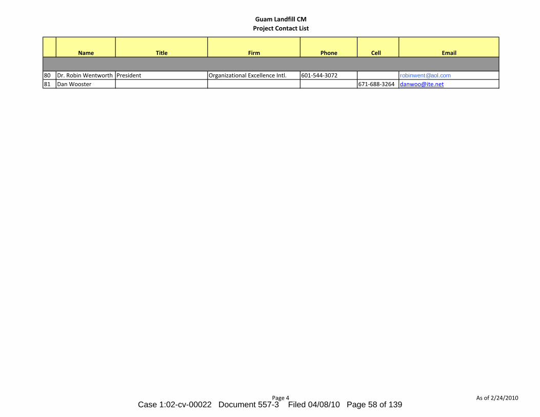
Guam Landfill CMProject Contact List
Name Title Firm Phone Cell Email
80 Dr. Robin Wentworth President Organizational Excellence Intl. 601‐544‐3072 [email protected] Dan Wooster 671‐688‐3264 [email protected]
Page 4 As of 2/24/2010Case 1:02-cv-00022 Document 557-3 Filed 04/08/10 Page 58 of 139

APPENDIX C
Case 1:02-cv-00022 Document 557-3 Filed 04/08/10 Page 59 of 139
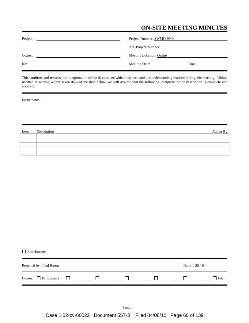
Page 1
ON-SITE MEETING MINUTES Project:
Owner: Re:
Project Number: SWMD-09-0 A/E Project Number: Meeting Location: Onsite Meeting Date: Time:
This confirms and records our interpretation of the discussions which occurred and our understanding reached during this meeting. Unless notified in writing within seven days of the date below, we will assume that the following interpretation or description is complete and accurate. Participants:
Item Description Action By
Attachments Prepared by: Paul Baron Date: 1-25-10 Copies: Participants File
Case 1:02-cv-00022 Document 557-3 Filed 04/08/10 Page 60 of 139

APPENDIX D
Case 1:02-cv-00022 Document 557-3 Filed 04/08/10 Page 61 of 139

SAMPLE
Case 1:02-cv-00022 Document 557-3 Filed 04/08/10 Page 62 of 139

SAMPLE
Case 1:02-cv-00022 Document 557-3 Filed 04/08/10 Page 63 of 139

APPENDIX E
Case 1:02-cv-00022 Document 557-3 Filed 04/08/10 Page 64 of 139

Page 1 of 14
Date: 01-20-10CM Project Manager: Paul BaronJob Number : 04052.09002Project Number: SMWD-09-02
Spec Section Submittal Rev Title01300 Administrative Requirements
1.3 001 Professional Land Surveyor Qualifications002 Copy of Site Drawings & Certificate signed by the Professional Land Surveyor
01323 Network Analysis Schedules1.6 001 Preliminary Network Diagram defining Planned Operations for first 60 days of work,
with General Outline for remainder of Work002 Draft of Proposal Complete Network Diagram for review
003 Complete Network Diagram consisting of Network Diagrams & Mathematic Analysis004a Updated Network Schedule for Progress Payment 1004b Updated Network Schedule for Progress Payment 2004c Updated Network Schedule for Progress Payment 3004d Updated Network Schedule for Progress Payment 4004e Updated Network Schedule for Progress Payment 5004f Updated Network Schedule for Progress Payment 6004g Updated Network Schedule for Progress Payment 7004h Updated Network Schedule for Progress Payment 8004i Updated Network Schedule for Progress Payment 9004j Updated Network Schedule for Progress Payment 10004k Updated Network Schedule for Progress Payment 11004l Updated Network Schedule for Progress Payment 12
004m Updated Network Schedule for Progress Payment 13004n Updated Network Schedule for Progress Payment 14004o Updated Network Schedule for Progress Payment 15004p Updated Network Schedule for Progress Payment 16004q Updated Network Schedule for Progress Payment 17
01330 Submittal Procedures1.2 001 Sample Submittal Form1.3 002 Proposed Products List1.4 003 Sample Product Data Form
1.13 004a Photographs of Site Conditions & Construction for Progress Payment 1004b Photographs of Site Conditions & Construction for Progress Payment 2004c Photographs of Site Conditions & Construction for Progress Payment 3004d Photographs of Site Conditions & Construction for Progress Payment 4004e Photographs of Site Conditions & Construction for Progress Payment 5004f Photographs of Site Conditions & Construction for Progress Payment 6004g Photographs of Site Conditions & Construction for Progress Payment 7004h Photographs of Site Conditions & Construction for Progress Payment 8004i Photographs of Site Conditions & Construction for Progress Payment 9004j Photographs of Site Conditions & Construction for Progress Payment 10004k Photographs of Site Conditions & Construction for Progress Payment 11004l Photographs of Site Conditions & Construction for Progress Payment 12
004m Photographs of Site Conditions & Construction for Progress Payment 13004n Photographs of Site Conditions & Construction for Progress Payment 14004o Photographs of Site Conditions & Construction for Progress Payment 15004p Photographs of Site Conditions & Construction for Progress Payment 16004q Photographs of Site Conditions & Construction for Progress Payment 17
01400 Quality Requirements 1.6 001 List of intended Manufacturer Field Services
01500 Temporary Facilities & Controls 1.2 001 Recycling Plan including a List of Materials that might be Recycled
1.10 002 Proposed Field Office & Parking Layout1.14 003 Project Sign1.17 004 Qualifications for Fire Prevention & Protection Responsible Person
ANTICIPATED SUBMITTALS LIST
Layon Municipal Sanitary Landfill Entrance Area Facilities and Cells 1 and 2
Case 1:02-cv-00022 Document 557-3 Filed 04/08/10 Page 65 of 139

Page 2 of 14
Date: 01-20-10CM Project Manager: Paul BaronJob Number : 04052.09002Project Number: SMWD-09-02
Spec Section Submittal Rev Title
ANTICIPATED SUBMITTALS LIST
Layon Municipal Sanitary Landfill Entrance Area Facilities and Cells 1 and 2
1.18 005 Security Program1.19 006 Water Control Plan1.20 007 Dust Control Plan1.21 008 Erosion & Sediment Plan1.22 009 Noise Control Plan1.23 010 Pest Control Plan1.24 011 Pollution Control Plan1.25 012 Rodent Control Plan
01700 Execution Requirements1.3 001 Written Report that Equipment or System has been Properly Installed & Functioning
Properly1.7 002 Project Record Documents & Actual Revisions to the Work (Review Monthly w/PP)1.8 003 Operation & Maintenance Instructions1.9 004 Three Copies of Preliminary Drafts of Manual for Materials & Finishes before Start of
Work005 One Completed Volume 15 days prior to Final Inspection006
Two Sets of Revised Final Volumes in Final Form within 10 days after Final Inspection1.10 007 Three Copies of Preliminary Drafts of Manual for Equipment & Systems
008 One Completed Volume 15 days prior to Final Inspection009
Two Sets of Revised Final Volumes in Final Form within 10 days after Final Inspection1.12 010 Product Warranties & Bonds prior to Final Application for Payment
01770 Project Close Out3.1 001 Project Record Drawings to be submitted before Final Inspection Request
002 Product Warranties & Bonds prior to Final Inspection Request3.2 003 Written Certification that Project is Substantially Complete
004 List of Deficiencies to be Corrected before Final Acceptance3.3 005 Letter of Acceptance
02055 Soils 1.4 001 Test Data for Controlled Fill & Select Fill
02060 Aggregate1.4 001 Name of Imported Fill Material Suppliers & Test Data
2.1A 002 Coarse Aggregate; 2" Minus Drain Rock2.1B 003 Subbase Course Aggregate2.1C 004 Base Course Coars Aggregate2.2A 005 Proposed 1/2" Bedding Sand
02225 Low Permeability Soil Liner1.4 001 Information & Test Results for Proposed Soil Material
002 Work Plan for the Test Pad & Method of Mixing & Constructing the Low Permeability Soil Liner
2.1 003a Moisture Content Test Results003b Particle Size Test Results003c Atterberg Limits003d Laboratory Compaction Test Results003e Laboratory Hydraulic Conductivity at a Specified Compaction
02230 Site Clearing1.2 001 Product Data for Herbicide
02240 Gravel Drainage Media1.4 001 Results of Conformance Tests
2.01 002 Proposed Gravel Drainage Media Materials 02250 Protective Soil Cover
1.4 001 Source Evaluation Tests Results02320 Backfill
Case 1:02-cv-00022 Document 557-3 Filed 04/08/10 Page 66 of 139

Page 3 of 14
Date: 01-20-10CM Project Manager: Paul BaronJob Number : 04052.09002Project Number: SMWD-09-02
Spec Section Submittal Rev Title
ANTICIPATED SUBMITTALS LIST
Layon Municipal Sanitary Landfill Entrance Area Facilities and Cells 1 and 2
1.3 001 Materials Source including Name of Imported Fill Materials Suppliers & Test Data002 Manufacturer's Certificate
02324 Termite Control 1.3 001 Product Data on Toxicants to be used, Composition by Percentage, Dilution
Schedule, Intended Application Rate (Include Product Label Information)002 Test Reports003 Manufacturer's Application Instructions 004 Manufacturer's Certificate
1.4 005 Project Record Documents006 Operation & Maintenance Data
02512 Site Water Distribution1.4 001 Product Data on Pipe Materials, Pipe Fittings, Valves, & Accessories1.5 002 Project Record Documents
003 Identify & Describe Discovery of Uncharted Utilities02532 Wastewater Pumping Stations (Leachate Only)
1.7 001a Guide Rail System001b Miscellaneous Metal Fabrications001c Pump Performance Curves001d Wiring Diagrams001e Pump Outline Drawing001f Motor Data001g Control Drawing & Data001h Operations & Maintenance Data002 Shop Drawings indicating Layout for all Leachate Sump Collection Pumps003 Product Data004 Test Reports005 Manufacturer's Installation Instructions006 Manufacturer's Certificate007 Manufacturer's Field Reports008 Start-up Report before Final Acceptance of Pumps
1.8 009 Execution Requirements010 Record of Actual Locations of Packaged Pumping Stations011 Executed Certification of Pumping Stating After Performance Testing 012 Spare Parts List & Rebuild Kits 013 Operations & Maintenance Manuals
02536001 Certificate of Compliance 002 Proposed Equipment and Methods003 Manufacturers Installation Instructions 004 Manufacturer's Certificate
02538 Sanitary System 1.5 001 Product Data indicating Pipe Material Used & Pipe Accessories
02577 Pavement Markings1.4 001 Manufacturer's Printed Product Data Sheets
02630 Storm Drainage1.3 001 Product Data indicating Pipe, Pipe Accessories, & Catch Basins & Grates
002 Manufacturer's Installation Instructions1.4 003
j g p , , Catch Basins, Cleanouts, & Invert Elevations
02640 Slope Protection Rock1.4.1 001 Source Evaluation Tests Results of Slope Protection Rock to be Supplied1.4.2 002a Reports on Quality Control Tests conducted by the Manufacturer1.4.2 002b Specification for Geotextile including All Properties published by the Manufacturer1.4.2 002c
Written Certification that Manufacturer inspected Geotextile to be Needle-Free
Case 1:02-cv-00022 Document 557-3 Filed 04/08/10 Page 67 of 139
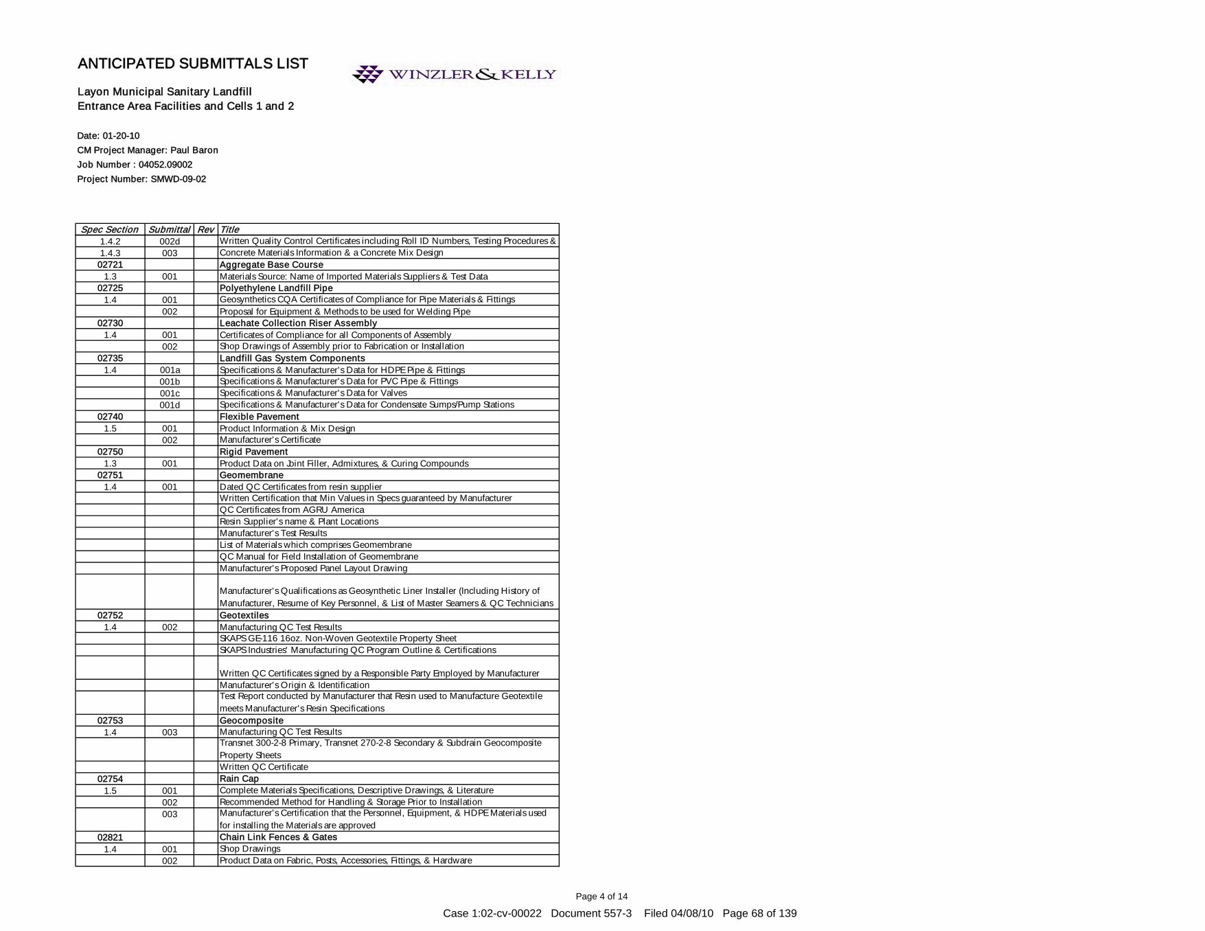
Page 4 of 14
Date: 01-20-10CM Project Manager: Paul BaronJob Number : 04052.09002Project Number: SMWD-09-02
Spec Section Submittal Rev Title
ANTICIPATED SUBMITTALS LIST
Layon Municipal Sanitary Landfill Entrance Area Facilities and Cells 1 and 2
1.4.2 002d Written Quality Control Certificates including Roll ID Numbers, Testing Procedures & 1.4.3 003 Concrete Materials Information & a Concrete Mix Design
02721 Aggregate Base Course1.3 001 Materials Source: Name of Imported Materials Suppliers & Test Data
02725 Polyethylene Landfill Pipe1.4 001 Geosynthetics CQA Certificates of Compliance for Pipe Materials & Fittings
002 Proposal for Equipment & Methods to be used for Welding Pipe02730 Leachate Collection Riser Assembly
1.4 001 Certificates of Compliance for all Components of Assembly002 Shop Drawings of Assembly prior to Fabrication or Installation
02735 Landfill Gas System Components 1.4 001a Specifications & Manufacturer's Data for HDPE Pipe & Fittings
001b Specifications & Manufacturer's Data for PVC Pipe & Fittings001c Specifications & Manufacturer's Data for Valves001d Specifications & Manufacturer's Data for Condensate Sumps/Pump Stations
02740 Flexible Pavement1.5 001 Product Information & Mix Design
002 Manufacturer's Certificate02750 Rigid Pavement
1.3 001 Product Data on Joint Filler, Admixtures, & Curing Compounds02751 Geomembrane
1.4 001 Dated QC Certificates from resin supplierWritten Certification that Min Values in Specs guaranteed by ManufacturerQC Certificates from AGRU AmericaResin Supplier's name & Plant LocationsManufacturer's Test ResultsList of Materials which comprises GeomembraneQC Manual for Field Installation of GeomembraneManufacturer's Proposed Panel Layout Drawing
Manufacturer's Qualifications as Geosynthetic Liner Installer (Including History of Manufacturer, Resume of Key Personnel, & List of Master Seamers & QC Technicians
02752 Geotextiles1.4 002 Manufacturing QC Test Results
SKAPS GE-116 16oz. Non-Woven Geotextile Property SheetSKAPS Industries' Manufacturing QC Program Outline & Certifications
Written QC Certificates signed by a Responsible Party Employed by ManufacturerManufacturer's Origin & IdentificationTest Report conducted by Manufacturer that Resin used to Manufacture Geotextile meets Manufacturer's Resin Specifications
02753 Geocomposite 1.4 003 Manufacturing QC Test Results
Transnet 300-2-8 Primary, Transnet 270-2-8 Secondary & Subdrain Geocomposite Property SheetsWritten QC Certificate
02754 Rain Cap1.5 001 Complete Materials Specifications, Descriptive Drawings, & Literature
002 Recommended Method for Handling & Storage Prior to Installation003 Manufacturer's Certification that the Personnel, Equipment, & HDPE Materials used
for installing the Materials are approved02821 Chain Link Fences & Gates
1.4 001 Shop Drawings002 Product Data on Fabric, Posts, Accessories, Fittings, & Hardware
Case 1:02-cv-00022 Document 557-3 Filed 04/08/10 Page 68 of 139

Page 5 of 14
Date: 01-20-10CM Project Manager: Paul BaronJob Number : 04052.09002Project Number: SMWD-09-02
Spec Section Submittal Rev Title
ANTICIPATED SUBMITTALS LIST
Layon Municipal Sanitary Landfill Entrance Area Facilities and Cells 1 and 2
003 Manufacturer's Installation Instruction1.5 004 Project Record Documents indicating Actual Locations of Property Perimeter Posts
Relative to Property Lines & Easements005 Operations & Maintenance Data
02924 Seeding & Soil Supplements1.2 001 Product Data for Seed Mix, Fertilizer, Mulch, & other Accessories
002 Test Reports indicating Topsoil Nutrient & PH Levels with Recommended Soil Supplements & Application Rates
003 Manufacturer's Certificate1.3 004 Operation & Maintenance Data
03110 Concrete Formwork1.2.1 001 Shop Drawings showing Details of Formwork, including Dimensions of Joints,
Supports, Studding & Shoring, & Sequence of Form & Shoring Removal03210 Reinforcing Steel1.2.1 001 Shop Drawings showing Reinforcing Steel Placement, Schedules, Sizes, Grades, &
Splicing & Bending Details1.2.2 002 Certified Copies of Mill Reports attesting that the Reinforcing Steel Furnished contains
no less than 25% Recycled Scrap Steel03300 Cast-in-Place Concrete1.2.1 001 Name & Manufacturer of each Cementitious Material, Admixture, Curing Compound,
& Aggregate Source.1.2.2 002 Concrete Mix Design for Approval prior to the use of the Concrete Mix1.2.3 003 Methods of Repair or Replacement directed by the Contracting Officer
03351 Metallic Concrete Topping1.4 001
Product Data including Manufacturer's Technical Bulletins & MSDS for each Product002 Samples of 2"x2" Specified Topping Section for Verification003 List of Project References as Documented in this Specification under Quality
Assurance Article, including Contact Name & Phone Number of Overseer004 Quality Control Submittals of Protection Plan of Surrounding Areas & Non-
Cementitious Surfaces04200 Masonry1.2.1 001 Shop Drawings of Plans, Elevations, & Details of Wall Reinforcement, Reinforcing
Bars at Corners & Wall Intersections, Offsets, Tops, Bottoms, & Ends of Walls, Control & Expansion Joints, Lintels, & Wall Openings.
05120 Structural Steel1.3.1 001 Fabrication Drawings, including Description of Connections
002 Erection Plan, including Description of Temporary Supports1.3.2 003 Product Data of Shop Primer1.3.3 004 Certificates for Steel, Bolts, Nuts, Washers, Welding Electrodes & Rods, & Non-Shrink
Grout05300 Steel Decking1.2.1 001
Fabrication Drawings including Type, Configuration, Structural Properties, Location, Necessary Details of Deck Units, Accessories, Supporting Members, Size & Location of Holes to be cut, Reinforcement to be provided, Location & Sequence of Welded Connections, & the Manufacturer's Erection Instruction
1.2.2 002 Product Data including Design Computations for Structural Properties of the Deck Units or SDI Certification that the Units are Designed in accordance with SDI Specifications
1.2.3 003 Manufacturer's Certificates Attesting that Decking Material meets Specified Requirements
05520 Handrails & Railings
Case 1:02-cv-00022 Document 557-3 Filed 04/08/10 Page 69 of 139

Page 6 of 14
Date: 01-20-10CM Project Manager: Paul BaronJob Number : 04052.09002Project Number: SMWD-09-02
Spec Section Submittal Rev Title
ANTICIPATED SUBMITTALS LIST
Layon Municipal Sanitary Landfill Entrance Area Facilities and Cells 1 and 2
1.4 001 Shop Drawings indicating Profiles, Sizes, Connection Attachments, Anchorage, Size & Type of Fasteners, & Accessories
06114 Wood Blocking & Curbing1.3 001 Technical Data on Wood Preservative & Fire Retardant Treatment Materials &
Application Instructions06410 Custom Cabinets
1.4 001 Shop Drawings indicating Materials, Component Profiles & Elevations, Assembly Methods, Joint Details, Fastening Methods, Accessory Listings, Hardware Location, & Schedule of Finishes
002 Product Data for Hardware Accessories 07140 Fluid-Applied Waterproofing
1.4 001 Shop Drawings Indicating Special Joint or Termination Conditions & Conditions of Interface with other Materials
002Product Data for Surface Primer, Flexible Flashings, Joint Cover Sheet, & Joint & Crack Sealants, with Temperature Range for Application of Waterproofing Membrane
003 Manufacturer's Installation Special Procedures & Perimeter Conditions Requiring Special Attention
004 Manufacturer's Certificate005 Manufacturer's Warranty
07213 Batt Insulation1.4 001 Manufacturer's Product Data for Batt Insulation & Board Insulation, & Pressure
Sensitive Tape002 Manufacturer's Certificate
07260 Vapor Retarders1.4 001
Product Data indicating Material Characteristics, Performance Criteria, & Limitations002 Manufacturer's Installation Instruction indication Preparation, & Installation
Requirements Techniques07540 Fluid-Applied Roofing
1.3 001 Shop Drawings indicating Special Joint or Termination Conditions & Conditions of Interface with other Materials
002Product Data for Material Description, Physical Properties, Recommended Storage Conditions, Shelf Life, Precautions, Flexible Flashings, Joint Cover Sheet, & Joint & Crack Sealants, with Temperature Range for Application of Waterproofing Membrane
003 Manufacturer's Installation Instructions indicating Special Procedures & Perimeter Conditions Requiring Special Attention
07620 Sheet Metal Flashing & Trim1.4 001 Shop Drawings indicating Material Profile, Jointing Pattern, Jointing Details, Fastening
Methods, Flashings, Terminations, & Installation Details002
Product Data on Manufactured Components, Metal Types, Finishes, & Characteristics07900 Joint Sealers
1.3 001 Product Data indicating Sealant Chemical Characteristics, Performance Criteria, Substrate Preparations, Limitations, & Color Availability
002 Manufacturer's Installation Instructions including Special Procedures for Surface Preparation, & Perimeter Conditions Requiring Special Attention
003 Manufacturer's Warranty 08114 Standard Steel Doors
1.3 001 Shop Drawings indicating Door Elevations, Internal Reinforcement, Closure Method, & Finishes
002 Product Data detailing Door Configurations, Location of Cut-outs for Hardware Reinforcement
Case 1:02-cv-00022 Document 557-3 Filed 04/08/10 Page 70 of 139
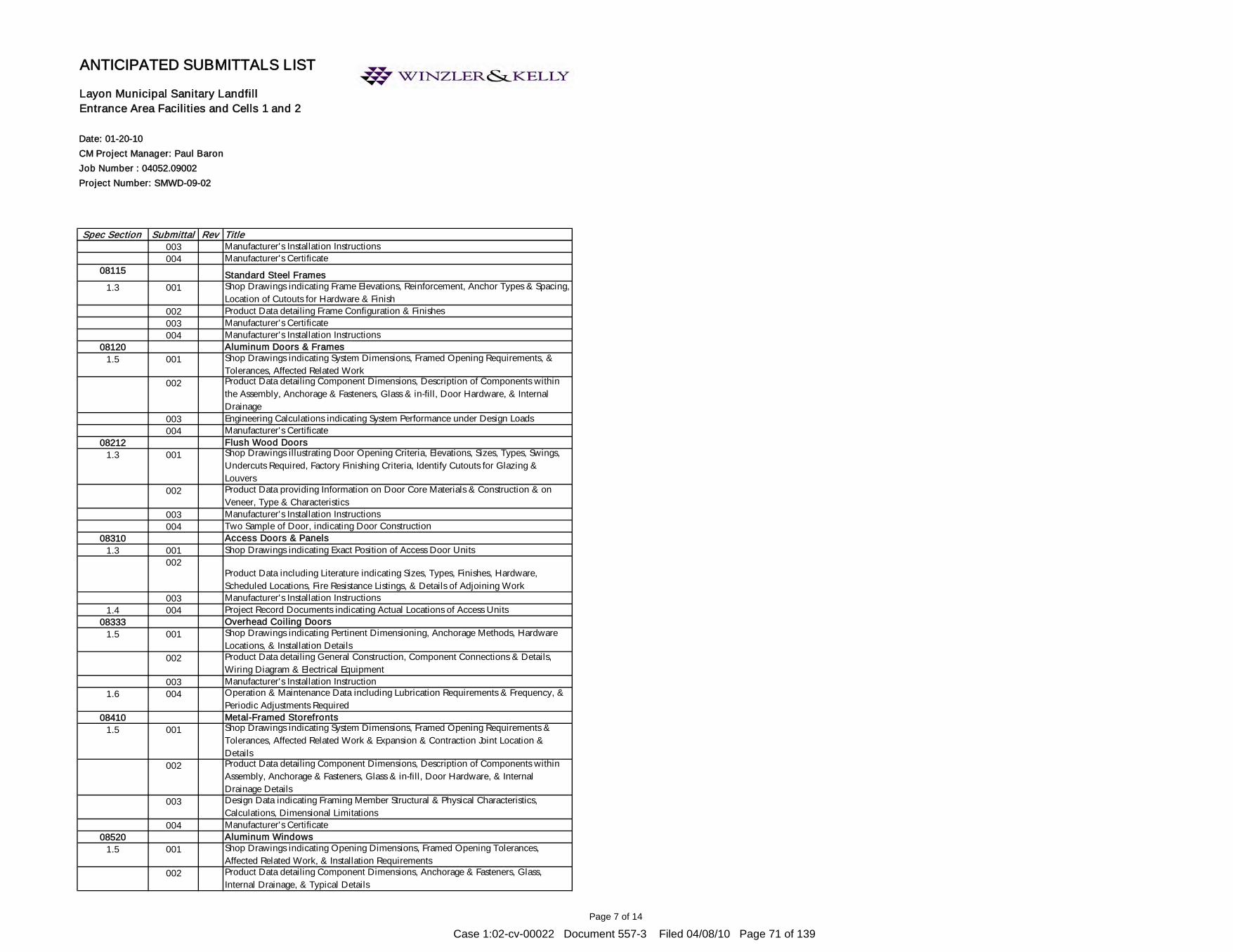
Page 7 of 14
Date: 01-20-10CM Project Manager: Paul BaronJob Number : 04052.09002Project Number: SMWD-09-02
Spec Section Submittal Rev Title
ANTICIPATED SUBMITTALS LIST
Layon Municipal Sanitary Landfill Entrance Area Facilities and Cells 1 and 2
003 Manufacturer's Installation Instructions004 Manufacturer's Certificate
08115 Standard Steel Frames1.3 001 Shop Drawings indicating Frame Elevations, Reinforcement, Anchor Types & Spacing,
Location of Cutouts for Hardware & Finish002 Product Data detailing Frame Configuration & Finishes003 Manufacturer's Certificate004 Manufacturer's Installation Instructions
08120 Aluminum Doors & Frames1.5 001 Shop Drawings indicating System Dimensions, Framed Opening Requirements, &
Tolerances, Affected Related Work002 Product Data detailing Component Dimensions, Description of Components within
the Assembly, Anchorage & Fasteners, Glass & in-fill, Door Hardware, & Internal Drainage
003 Engineering Calculations indicating System Performance under Design Loads004 Manufacturer's Certificate
08212 Flush Wood Doors1.3 001 Shop Drawings illustrating Door Opening Criteria, Elevations, Sizes, Types, Swings,
Undercuts Required, Factory Finishing Criteria, Identify Cutouts for Glazing & Louvers
002 Product Data providing Information on Door Core Materials & Construction & on Veneer, Type & Characteristics
003 Manufacturer's Installation Instructions004 Two Sample of Door, indicating Door Construction
08310 Access Doors & Panels1.3 001 Shop Drawings indicating Exact Position of Access Door Units
002Product Data including Literature indicating Sizes, Types, Finishes, Hardware, Scheduled Locations, Fire Resistance Listings, & Details of Adjoining Work
003 Manufacturer's Installation Instructions1.4 004 Project Record Documents indicating Actual Locations of Access Units
08333 Overhead Coiling Doors1.5 001 Shop Drawings indicating Pertinent Dimensioning, Anchorage Methods, Hardware
Locations, & Installation Details002 Product Data detailing General Construction, Component Connections & Details,
Wiring Diagram & Electrical Equipment003 Manufacturer's Installation Instruction
1.6 004 Operation & Maintenance Data including Lubrication Requirements & Frequency, & Periodic Adjustments Required
08410 Metal-Framed Storefronts1.5 001 Shop Drawings indicating System Dimensions, Framed Opening Requirements &
Tolerances, Affected Related Work & Expansion & Contraction Joint Location & Details
002 Product Data detailing Component Dimensions, Description of Components within Assembly, Anchorage & Fasteners, Glass & in-fill, Door Hardware, & Internal Drainage Details
003 Design Data indicating Framing Member Structural & Physical Characteristics, Calculations, Dimensional Limitations
004 Manufacturer's Certificate08520 Aluminum Windows
1.5 001 Shop Drawings indicating Opening Dimensions, Framed Opening Tolerances, Affected Related Work, & Installation Requirements
002 Product Data detailing Component Dimensions, Anchorage & Fasteners, Glass, Internal Drainage, & Typical Details
Case 1:02-cv-00022 Document 557-3 Filed 04/08/10 Page 71 of 139
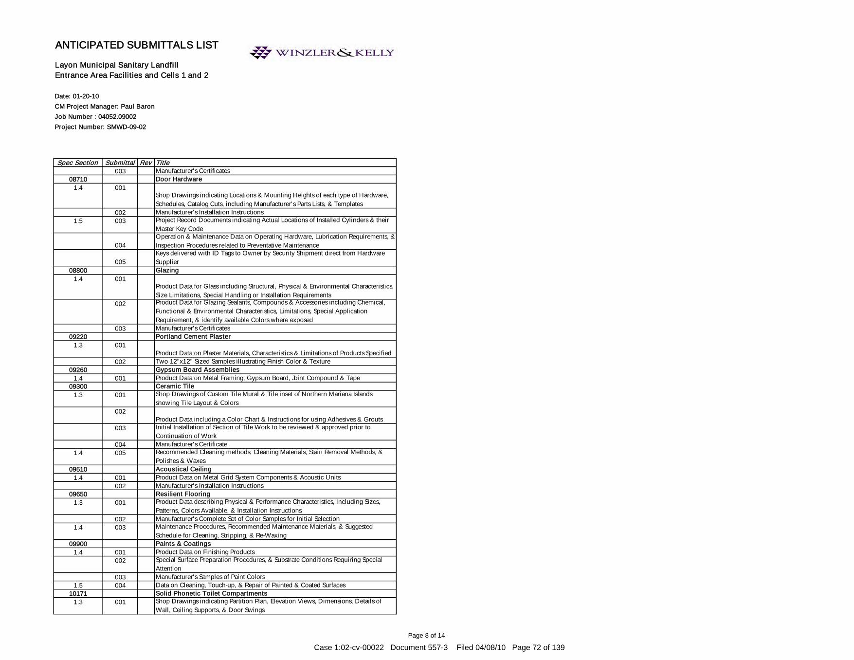
Page 8 of 14
Date: 01-20-10CM Project Manager: Paul BaronJob Number : 04052.09002Project Number: SMWD-09-02
Spec Section Submittal Rev Title
ANTICIPATED SUBMITTALS LIST
Layon Municipal Sanitary Landfill Entrance Area Facilities and Cells 1 and 2
003 Manufacturer's Certificates08710 Door Hardware
1.4 001Shop Drawings indicating Locations & Mounting Heights of each type of Hardware, Schedules, Catalog Cuts, including Manufacturer's Parts Lists, & Templates
002 Manufacturer's Installation Instructions1.5 003 Project Record Documents indicating Actual Locations of Installed Cylinders & their
Master Key Code
004Operation & Maintenance Data on Operating Hardware, Lubrication Requirements, & Inspection Procedures related to Preventative Maintenance
005Keys delivered with ID Tags to Owner by Security Shipment direct from Hardware Supplier
08800 Glazing1.4 001
Product Data for Glass including Structural, Physical & Environmental Characteristics, Size Limitations, Special Handling or Installation Requirements
002 Product Data for Glazing Sealants, Compounds & Accessories including Chemical, Functional & Environmental Characteristics, Limitations, Special Application Requirement, & identify available Colors where exposed
003 Manufacturer's Certificates09220 Portland Cement Plaster
1.3 001Product Data on Plaster Materials, Characteristics & Limitations of Products Specified
002 Two 12"x12" Sized Samples illustrating Finish Color & Texture09260 Gypsum Board Assemblies
1.4 001 Product Data on Metal Framing, Gypsum Board, Joint Compound & Tape09300 Ceramic Tile
1.3 001 Shop Drawings of Custom Tile Mural & Tile inset of Northern Mariana Islands showing Tile Layout & Colors
002Product Data including a Color Chart & Instructions for using Adhesives & Grouts
003 Initial Installation of Section of Tile Work to be reviewed & approved prior to Continuation of Work
004 Manufacturer's Certificate1.4 005 Recommended Cleaning methods, Cleaning Materials, Stain Removal Methods, &
Polishes & Waxes09510 Acoustical Ceiling
1.4 001 Product Data on Metal Grid System Components & Acoustic Units002 Manufacturer's Installation Instructions
09650 Resilient Flooring1.3 001 Product Data describing Physical & Performance Characteristics, including Sizes,
Patterns, Colors Available, & Installation Instructions002 Manufacturer's Complete Set of Color Samples for Initial Selection
1.4 003 Maintenance Procedures, Recommended Maintenance Materials, & Suggested Schedule for Cleaning, Stripping, & Re-Waxing
09900 Paints & Coatings1.4 001 Product Data on Finishing Products
002 Special Surface Preparation Procedures, & Substrate Conditions Requiring Special Attention
003 Manufacturer's Samples of Paint Colors1.5 004 Data on Cleaning, Touch-up, & Repair of Painted & Coated Surfaces
10171 Solid Phonetic Toilet Compartments1.3 001 Shop Drawings indicating Partition Plan, Elevation Views, Dimensions, Details of
Wall, Ceiling Supports, & Door Swings
Case 1:02-cv-00022 Document 557-3 Filed 04/08/10 Page 72 of 139

Page 9 of 14
Date: 01-20-10CM Project Manager: Paul BaronJob Number : 04052.09002Project Number: SMWD-09-02
Spec Section Submittal Rev Title
ANTICIPATED SUBMITTALS LIST
Layon Municipal Sanitary Landfill Entrance Area Facilities and Cells 1 and 2
002 Product Data on Panel Construction, Hardware, & Accessories003 Two 6"x6" Sized Samples illustrating Panel Finish, Color, & Sheen004 Special Procedures, Perimeter Conditions Requiring Special Attention
10440 Signs1.3 001 Shop Drawings indicating Sign Styles, Letting Font, Foreground & Background Colors,
002 Installation Template & Attachment Devices10500 Lockers
1.3 001 Shop Drawings indicating Locker Plan Layout & Numbering Plan002 Product Data on Locker Types, Sizes & Accessories003
Two 3"x6" Sized Samples of each Color Selected, Applied to Specified Base Metal004 Installation Template & Attachment Devices
10523 Fire Extinguishers & Cabinets1.4 001 Extinguisher Operational Features, Color & Finish, & Anchorage Details
002 Special Criteria & Wall Opening Coordination Requirements1.5 003 Test, Refill or Recharge Schedules & Re-Certification Requirements
10716 Typhoon Shutters1.4 001 Shop Drawings coordinated with Window Schedule, Elevations of Shutter Units, Half-
Sized Sections, Thickness & Gages of Materials, Fastenings, Method of Anchorage, Size & Spacing of Anchors, & Location of Hardware
002 Shop Drawings of Schedule of Shutters003 Product Data for Accordion Shutters
1.8 004 Manufacturer's Operation & Maintenance Data10800 Toilet Accessories
1.3 001 Product Data on Accessories describing Size, Finish, Details of Function, Attachment Methods
002 Special Procedures, Conditions Requiring Special Attention13211 Ground Level Steel Tanks For Potable Water Storage, Leachate Storage, &
Subdrain Storage1.3 001 Fabrication and/or Erection Drawings including Construction Details & Materials of
Construction002 Product Technical Data including Acknowledgement that Products Submitted meet
Requirements of Standards Referenced, Manufacturer's Installation Instructions, Design Data, Manufacturer's List of Five Similar Sized Reservoirs, & Cathodic Protection System Design & Details
003 Test Reports004 Operation & Maintenance Manuals005 One 12"x12" Glass-Fused-to-Steel Reservoir Sample showing Actual Color prior to
Fabrication of Reservoirs15010 Basic Mechanical Requirements
1.6 001 Shop Drawings including Floor Plans, Sectional Views, Wiring Diagrams, & Installation Details of Equipment, & Equipment Spaces identifying & indicating Proposed Location, Layout & Arrangement of Items of Equipment, Control Panels, Accessories, & Piping Ductwork.
002 Descriptive Literature of Cataloged Products, Equipment Drawings, Diagrams, Performance & Characteristic Curves, & Catalog Cuts
003 Proof of Conformance with ANSI, ASTM, NEMA, & UL004 Certificates of Conformance or Compliance from the Manufacturer attesting that
Materials & Equipment to be furnished for this Project comply with Requirements of Specifications
15121 Piping Expansion Compensation
Case 1:02-cv-00022 Document 557-3 Filed 04/08/10 Page 73 of 139

Page 10 of 14
Date: 01-20-10CM Project Manager: Paul BaronJob Number : 04052.09002Project Number: SMWD-09-02
Spec Section Submittal Rev Title
ANTICIPATED SUBMITTALS LIST
Layon Municipal Sanitary Landfill Entrance Area Facilities and Cells 1 and 2
1.3 001 Details of Flexible Pipe Connectors indicating Maximum Temperature & Pressure Rating, Face-to-Face Length, Live Length, Hose Wall Thickness, Hose Convolutions per Foot (Meter) & per Assembly, Fundamental Frequency of Assembly, Braid Structure, Total Number of Wires in Braid, & Adjustment Instructions
002 Manufacturer's Installation Instructions indicating Special Procedures & External Controls
15140 Supports & Anchors1.4 001 Manufacturer's Catalog Data detailing Load Capacity
002 Manufacturer's Installation Instructions indicating Special Procedures & Assembly of Components
003 Support & Bracing Shop Drawings including Plans, Sections, Details, Schedules & other Information necessary to describe Supports, Hangers & Seismic Bracing for all Mechanical Systems, Equipment, Piping & Ductwork (Indicate Location & Type of all Hangers, Supports, & Seismic Bracing)
004 Maintenance Data & Parts List for each Type of Support & Anchor15170 Motors
1.4 001 Wiring Diagrams with Electrical Characteristics & Connection Requirements002 Test Reports indicating Test Results verifying Nominal Efficiency & Power Factor for
Three-Phase Motors larger than 5 Horsepower003 Manufacturer's Installation Instructions indicating Setting, Mechanical Connections,
Lubrication, & Wiring Instructions15190 Mechanical Identification
1.4 001 Wording, Symbols, Letter Size, & Color Coding for Mechanical Identification002 Valve Chart & Schedule, including Valve Tag Number, Location, Function, & Valve
Manufacturer's Name & Model Number003 Manufacturer's Catalog Literature for each Product Required004 Two Samples for each Product005
Manufacturer's Installation Instructions indicating Special Procedures & Installation15245 Vibration Isolation
1.4 001Shop Drawings indicating Inertia Bases, Location of Vibration Isolators & Seismic Restraint, including Details of Suspension for Ceiling-Hung Equipment
002 Catalog Cuts of Vibration Isolators & Seismic Restraints003 Manufacturer's Installation Instructions indicating Special Procedures & Setting
Dimensions004 Seismic Certification & Analysis005 Code Requirements
15260 Piping Insulation1.4 001 Product Description, Thermal Characteristics, List of Materials & Thickness for each
Service, & Locations1.5 002 Installation Procedures
15290 Ductwork Insulation1.4 001 Product Description, Thermal Characteristics, List of Materials & Thickness for each
Service, & Locations002 Two Samples of any Representative Size illustrating each Insulation Type
1.5 003 Installation Procedures15320 Fire Pump
1.6 001 Manufacturer's Literature including General Assembly, Pump Curves showing 002 Shop Drawings indicating Layout, General Assembly, Components, Dimensions,
Weights, Clearances, & Methods of Assembly1.7 003 Results of Hydrostatic Test & Field Acceptance Tests performed
Manufacturer's Instructions indicating Support Details & Connection Requirements for Fire Pump System
Case 1:02-cv-00022 Document 557-3 Filed 04/08/10 Page 74 of 139

Page 11 of 14
Date: 01-20-10CM Project Manager: Paul BaronJob Number : 04052.09002Project Number: SMWD-09-02
Spec Section Submittal Rev Title
ANTICIPATED SUBMITTALS LIST
Layon Municipal Sanitary Landfill Entrance Area Facilities and Cells 1 and 2
1.8 004Project Record Documents indicating Actual Locations of Components & Accessories
005Certificates for Pump along with Summary & Results of Shop Tests performed
006 Operation Data including Manufacturer's Instructions, Start-up Data, & Troubleshooting Checklists for Pumps, Drivers, & Controllers
007 Manufacturer's Literature detailing Cleaning Procedures, Replacement Parts Lists, & Repair Data for Pump, Driver & Controller
15410 Plumbing Piping1.4 001 Product Data on Pipe Materials, Pipe Fittings, Valves, Accessories, & Manufacturer's
Catalog Information (Indicate Valve Data & Ratings)002 Complete Installation Shop Drawings indicating all Locations & Invert Elevations of
Plumbing Piping1.5 003 Project Record Documents indicating Actual Locations of Valves
15430 Plumbing Specialties1.4 001 Product Data detailing Component Sizes, Rough-in Requirements, Service Sizes, &
Finishes002 Shop Drawings indicating Dimensions, Weights, & Placement of Openings & Holes
1.5 003 Project Record Documents indicating Actual Locations of Equipment, Cleanouts, Backflow Preventers, & Water Hammer Arrestors
15440 Plumbing Fixtures1.3 001 Catalog illustrations of Fixtures, Sizes, Rough-in Dimensions, Utility Sizes, Trim, &
Finishes1.4 002 Manufacturer's Instructions indicating Installation Methods & Procedures1.5 003
Maintenance Data including Fixture Trim Exploded View & Replacement Parts List15450 Plumbing Equipment
1.4 001Dimension Drawings of Water Heaters indicating Components, Connections to other Equipment & Piping, Electrical Characteristics, & Connection Requirements
002 Operation & Maintenance Data including Operation, Maintenance & Inspection Data, Replacement Part Numbers & Availability, & Service Depot Location & Telephone Number
15481 Compressed Air System1.4 001 Manufacturer's Catalog Literature with Capacity, Weight, & Electrical Characteristics
& Connection Requirements002 Shop Drawings indicating Piping System Schematic with Electrical Characteristics &
Connection Requirements1.5 003 Inspector's Certificate for Air Receiver for Including in Operating & Maintenance
Manuals004 Manufacturer's Installation Instructions, Hoisting & Setting Requirements, Starting
Procedures1.6 005 Project Record Documents indicating Actual Locations of Equipment & Components
(Modify Shop Drawings to indicate Final Locations)006 Operation Data for Air Compressor, Air Receiver & Accessories, Aftercooler,
Refrigerated Air Dryer, & Pressure Reducing Station007 Maintenance Data for Air Compressor, Air Receiver & Accessories, Aftercooler, &
Pressure Reducing Station008 Manufacturer's Warranty
15484 Fuel Lube Oil Piping System1.4 001 Product Data on Pipe Materials, Pipe Fittings, Valves & Accessories, & Manufacturer's
Catalog Information (Indicate Valve Data & Ratings)002 Shop Drawings indicating Tanks, System Layout, Pipe Sizes, Location, & Elevations
1.5 003 Project Record Documents indicating Actual Locations of Piping System, Storage
Case 1:02-cv-00022 Document 557-3 Filed 04/08/10 Page 75 of 139

Page 12 of 14
Date: 01-20-10CM Project Manager: Paul BaronJob Number : 04052.09002Project Number: SMWD-09-02
Spec Section Submittal Rev Title
ANTICIPATED SUBMITTALS LIST
Layon Municipal Sanitary Landfill Entrance Area Facilities and Cells 1 and 2
Maintenance Data including Installation Instructions, Spare Parts List, Exploded Assembly Views
004 Manufacturer's Warranty 15530 Leachate Sump Pumps
1.4 001 Complete Manufacturer's Data including Details of Electric Motors & Pump Curve002 Shop Drawings for Pump Installation including Mechanical & Electric Schematics
15535 Refrigerant Piping & Specialties1.5 001 Shop Drawings indicating Schematic Layout of System including Equipment, Critical
Dimensions & Sizes (Include Double Hot Gas Risers if recommended by Chiller Manufacturer to return Oil to Compressors)
002 Manufacturer's Catalog Information including Load Capacity003 Results of Leak Test & Acid Test004 Manufacturer's Installation Instructions indicating Support, Connection Requirements,
& Isolation for Servicing005 Welders Certification
1.6 006 Project Record Documents indicating Exact Locations of Equipment & Refrigeration Accessories on Record Drawings
1.7 007 Instructions for Changing Cartridges, Assembly Views, & Spare Parts Lists15540 Liquid Level Pressure Sensor
1.4 001 Complete Manufacturer's Specifications002
Shop Drawings for Pump Installation including Mechanical & Electric Schematics15545 Three-Point Level Sensor
1.4 001 Complete Manufacturer's Specifications002 Shop Drawings for Pump & Controls Installation including Mechanical & Electric
Schematics15550 Pump Control Panel
1.4 001 Complete Manufacturer's Specifications for Panels & Related Equipment002 Narrative Description & Logic Diagram for Control System003 Electrical Schematic & Single-Line Diagram
15560 Leachate Flow Meters1.4 001
Complete Manufacturer's Specifications for Flow Meters & Related Equipment002 Shop Drawings for Installation of Sensors & Display Units003 Electrical Schematic & Single-Line Diagram 004 Operation & Maintenance Manual For Flow Meter
Section Breakout Junction Box1.4 001 Complete Manufacturer's Specifications for Breakout Junction Box
002 Shop Drawings for Installation of Pumps & Controls003 Electrical Schematic & Single-Line Diagram
15671 Air-Cooled Condensing Units1.4 001 Shop Drawings indicating Components, Assembly, Dimensions, Weights & Loadings,
Required Clearances, & Location & Size of Field Connections (Include Layouts showing Condensing Units, Cooling Coils, Refrigerant Piping, & Accessories Required for Complete System)
002Rated Capacities, Weights Specialties & Accessories, Electrical Name Plate Data, & Wiring Diagrams (Submission with Air Handling Units should refer to Section 15855)
1.5 003 Design Data indicating Pipe SizingManufacturer's Installation Instructions
1.6 004 Operation & Maintenance Data including Start-up Instructions, Maintenance Instructions, Parts Lists, Controls, & Accessories
1.9 005 Manufacturer's Warranty 15855 Air Handling Units
Case 1:02-cv-00022 Document 557-3 Filed 04/08/10 Page 76 of 139

Page 13 of 14
Date: 01-20-10CM Project Manager: Paul BaronJob Number : 04052.09002Project Number: SMWD-09-02
Spec Section Submittal Rev Title
ANTICIPATED SUBMITTALS LIST
Layon Municipal Sanitary Landfill Entrance Area Facilities and Cells 1 and 2
1.4 001 Published Literature, & Data for Filters, Fans, Sound Power Level, & Electrical Requirements
002 Shop Drawings indicating Assembly, Unit Dimensions, Weight Loading, Required Clearances, Construction Details, Field Connection Details, & Electrical Characteristics & Connection Requirements
003 Manufacturer's InstructionsMaintenance Data including Instructions for Lubrication, Filter Replacement, Motor & Drive Replacement, Spare Parts Lists, & Wiring Diagrams
15890 Ductwork Accessories1.5 001
Shop Drawings indicating Duct Fittings, Particulars such as Gages, Sizes, Welds, & Configuration prior to Start of Work (Include Duct Supports with Sway Braces)
002 Product Data for Duct Materials1.6 003
Project Record Documents indicating Actual Locations of Ducts & Duct Fittings15910 Ductwork Accessories
1.4 001 Manufacturer's Installation Instructions indicating Fire Dampers & Combination Fire & Smoke Dampers
002 Project Record Documents indicating Actual Locations of Test Holes15940 Air Outlets & Inlets
1.4 001 Product Data for Equipment required for this Project & Schedule of Outlets & Inlets showing Type, Size, Location, Application, & Noise Level
1.5 002 Project Record Documents indicating Actual Locations of Air Outlets & Inlets15990 Testing, Adjusting, & Balancing
1.3 001 Test Reports002 Name & Qualification of Adjusting & Balancing Agency003
Field Reports indicating Deficiencies in System that would prevent Proper Testing, Adjusting, & Balancing of Systems & Equipment to achieve specified Performance
004 Draft Reports indicating Adjusting, Balancing, & Equipment Data Required005 Draft Copies of Report for Review006 Draft Report Indication Adjusting, Balancing, & Equipment Data.
1.4 007 Project Record Documents indicating Actual Locations of Flow Measuring Stations Balancing Valves & Rough Setting
16050 Basic Electrical Materials & Methods1.5.1 001 Manufacturer's Catalog Data 1.5.2 002 Drawings including Wiring Diagrams & Installation Details of Equipment1.5.3 003 Manufacturer's Instructions1.5.4 004 Manufacturer's Certificates
1.5.4.1 005 Reference Standard Compliance 1.5.4.2 006 Independent Testing Organization Certificate 1.5.5 007 Operation & Maintenance Manuals
1.5.5.1 008 Operating Instructions 16302 Underground Transmission & Distribution
1.3 001 Megger Test Reports for all 600-Volt Wire & Cable Tests2.0 002 Heat Fusion Work Plan
003 Pipe Joint Test Methods, Procedures, & Apparatus004 Product Data for Piping Materials005 Product Data for Fusion Equipment006 Test Reports for Heat Fusion Daily Logs007 Test Reports for Bent Strap Testing008 Test Reports for Ultrasonic Testing009 Certificate for Fusion Equipment Experience Requirements010 Certificate for Experience Requirements
Case 1:02-cv-00022 Document 557-3 Filed 04/08/10 Page 77 of 139

Page 14 of 14
Date: 01-20-10CM Project Manager: Paul BaronJob Number : 04052.09002Project Number: SMWD-09-02
Spec Section Submittal Rev Title
ANTICIPATED SUBMITTALS LIST
Layon Municipal Sanitary Landfill Entrance Area Facilities and Cells 1 and 2
011 Certification for NDE Technician012 Pipe Manufacturer Material Certificate013 Mechanical Coupling Manufacturer Certificate014 Certification for Heat Fusion Technician
2.4 015 Primary/Secondary and Communication Handhole Hardwares3.4 016 Underground Electrical Work
16402 Interior Distribution System1.3.1 001 Shop Drawings of Panel Boards & Wireways
1.3.2002 Product Data for Receptacles, Circuit Breakers, Switches, Enclosed Circuit Breakers,
Manual Motor Starters, CATV Outlets, Grounding Block
1.3.3003 Test Reports for 600-Volt Wiring Test, Grounding System Test, Ground-Fault
Receptacle Test1.5.1 004 Operation & Maintenance Manuals for Electrical Systems including Single-Line
Diagram of the "As-Built" Building Electrical System, & Schematic Diagram of Electrical Control System
16510 Interior Lighting1.4.1 001
Product Data for Fluorescent Lighting Fixtures, Electronic Ballasts & Lamps, Incandescent Lighting Fixtures & Lamps, Dimmer Switch, Lighting Contactor, Time Switch, Photocell Switch, Exit Signs, Emergency Lighting Equipment, Occupancy Sensors, Electronic Dimming Ballast, & Dimming Ballast Controls
1.4.2 002 Samples of Lighting Fixtures, complete with Lamps & Ballasts1.4.3 003 Operating Test Reports1.4.4 004 Operation & Maintenance Data showing all Control Modules, Control Zones,
Occupancy Sensors, Light Fixtures, & all Interconnecting Control Wire, Conduit, & Associated Hardware
2.1 005 Flourescent Light Fixtures2.1.5 006 Compact Flourescent Light Fixtures2.3 007 Emergency Light2.4 008 Exit Light
1.4.5 009 Information Card16520 Exterior Lighting
1.4 001 Luminaire Drawings including Poles002 Product Data on Luminaires, Lamps, Ballasts, Lighting Contactor, Time Switch,
Photocell Switch, Concrete Poles, & Brackets003 Operating Test Reports for Luminaires
16612 Emergency Power System1.0 001 Manufacturer's Brochures describing Equipment Ratings, Performances, Specification
& Construction002 Shop Drawings of Layout to Scale giving Dimensions, Schematic & Wiring Diagrams,
& Interconnection Diagrams003 Manufacturer's Warranty
16721 Fire Alarm System001 Technical Data, Wiring Diagrams, & Installation & Maintenance Instructions
Case 1:02-cv-00022 Document 557-3 Filed 04/08/10 Page 78 of 139
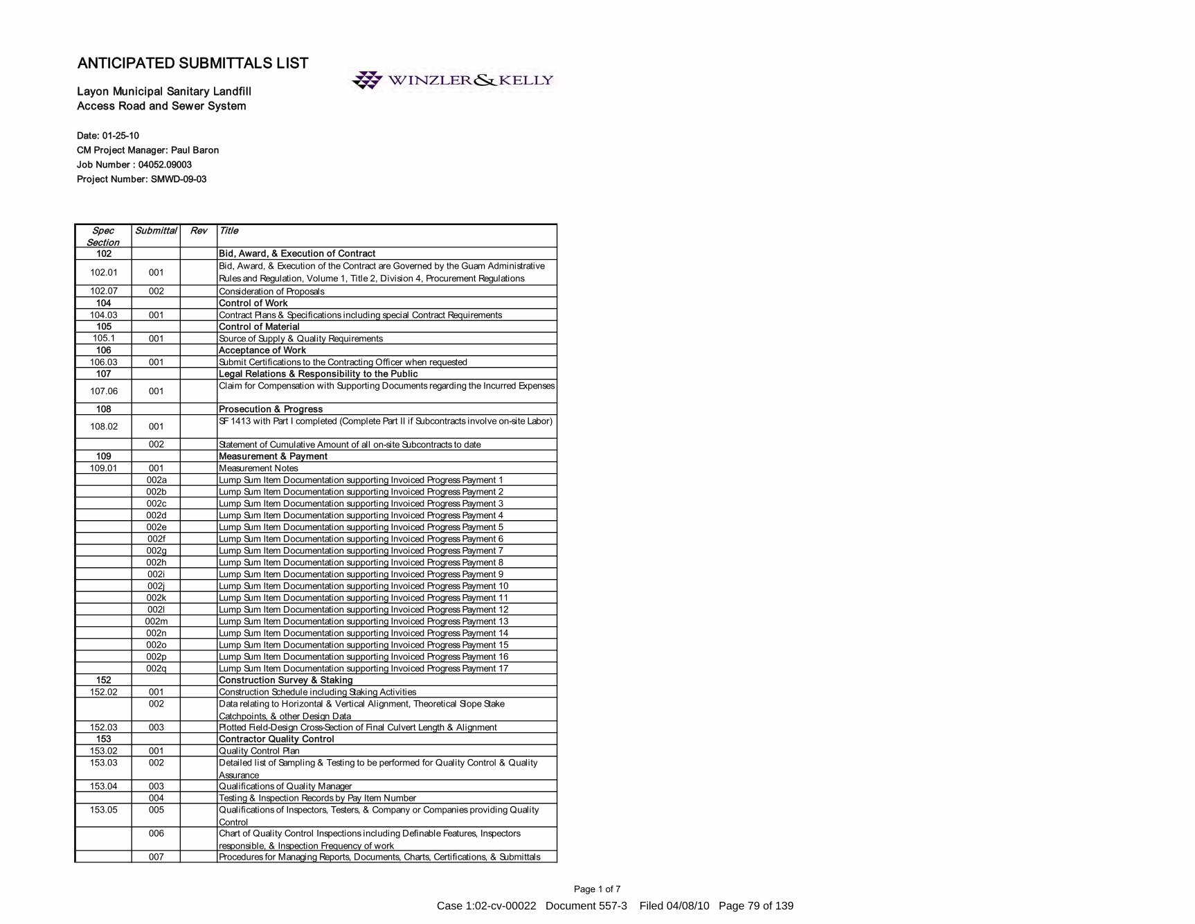
Page 1 of 7
Date: 01-25-10CM Project Manager: Paul BaronJob Number : 04052.09003Project Number: SMWD-09-03
Spec Section
Submittal Rev Title
102 Bid, Award, & Execution of Contract
102.01 001Bid, Award, & Execution of the Contract are Governed by the Guam Administrative Rules and Regulation, Volume 1, Title 2, Division 4, Procurement Regulations
102.07 002 Consideration of Proposals104 Control of Work
104.03 001 Contract Plans & Specifications including special Contract Requirements105 Control of Material
105.1 001 Source of Supply & Quality Requirements106 Acceptance of Work
106.03 001 Submit Certifications to the Contracting Officer when requested107 Legal Relations & Responsibility to the Public
107.06 001 Claim for Compensation with Supporting Documents regarding the Incurred Expenses
108 Prosecution & Progress
108.02 001 SF 1413 with Part I completed (Complete Part II if Subcontracts involve on-site Labor)
002 Statement of Cumulative Amount of all on-site Subcontracts to date109 Measurement & Payment
109.01 001 Measurement Notes002a Lump Sum Item Documentation supporting Invoiced Progress Payment 1002b Lump Sum Item Documentation supporting Invoiced Progress Payment 2002c Lump Sum Item Documentation supporting Invoiced Progress Payment 3002d Lump Sum Item Documentation supporting Invoiced Progress Payment 4002e Lump Sum Item Documentation supporting Invoiced Progress Payment 5002f Lump Sum Item Documentation supporting Invoiced Progress Payment 6002g Lump Sum Item Documentation supporting Invoiced Progress Payment 7002h Lump Sum Item Documentation supporting Invoiced Progress Payment 8002i Lump Sum Item Documentation supporting Invoiced Progress Payment 9002j Lump Sum Item Documentation supporting Invoiced Progress Payment 10002k Lump Sum Item Documentation supporting Invoiced Progress Payment 11002l Lump Sum Item Documentation supporting Invoiced Progress Payment 12002m Lump Sum Item Documentation supporting Invoiced Progress Payment 13002n Lump Sum Item Documentation supporting Invoiced Progress Payment 14002o Lump Sum Item Documentation supporting Invoiced Progress Payment 15002p Lump Sum Item Documentation supporting Invoiced Progress Payment 16002q Lump Sum Item Documentation supporting Invoiced Progress Payment 17
152 Construction Survey & Staking 152.02 001 Construction Schedule including Staking Activities
002 Data relating to Horizontal & Vertical Alignment, Theoretical Slope Stake Catchpoints, & other Design Data
152.03 003 Plotted Field-Design Cross-Section of Final Culvert Length & Alignment153 Contractor Quality Control
153.02 001 Quality Control Plan153.03 002 Detailed list of Sampling & Testing to be performed for Quality Control & Quality
Assurance153.04 003 Qualifications of Quality Manager
004 Testing & Inspection Records by Pay Item Number153.05 005 Qualifications of Inspectors, Testers, & Company or Companies providing Quality
Control006 Chart of Quality Control Inspections including Definable Features, Inspectors
responsible, & Inspection Frequency of work007 Procedures for Managing Reports, Documents, Charts, Certifications, & Submittals
Layon Municipal Sanitary Landfill Access Road and Sewer System
ANTICIPATED SUBMITTALS LIST
Case 1:02-cv-00022 Document 557-3 Filed 04/08/10 Page 79 of 139

Page 2 of 7
Date: 01-25-10CM Project Manager: Paul BaronJob Number : 04052.09003Project Number: SMWD-09-03
Spec Section
Submittal Rev Title
Layon Municipal Sanitary Landfill Access Road and Sewer System
ANTICIPATED SUBMITTALS LIST
153.06 008 Qualifications of Individuals & Company or Companies providing Quality Assurance
153.08 009 Notification of Completion of Work010 Construction Operations Report011 Quality Control & Assurance Report012 Control Charts013 Pay Item Measurement Notes (FHWA 17348 Pay Item Record)014 Quality Control & Quality Assurance Test Results
155 Schedules for Construction Contract 155.02 001 Preliminary Construction Schedule155.06 002a Updated Construction Schedule 1
002b Updated Construction Schedule 2002c Updated Construction Schedule 3002d Updated Construction Schedule 4002e Updated Construction Schedule 5002f Updated Construction Schedule 6002g Updated Construction Schedule 7002h Updated Construction Schedule 8002i Updated Construction Schedule 9
156 Public Traffic 156.03 001 Alternate Traffic Control Proposal156.07 002 Night Lighting System Proposal
157 Soil Erosion Control 157.01 001 Environmental Protection Plan (EPP), Erosion Control Plan (ECP), & Stormwater 157.03 002 Alternate Erosion Control Plan Proposal with all Necessary Permits
203 Removal of Structures & Observation 203.01 001 Action Plan for the relocation of Existing School Bus Shelters
213 Subgrade Stabilization213.03 001 Subgrade Stabilization Mix Design including Minimum Compressive Strengths
253 Gabions & Revet Mattresses253.03 001 Installation Drawings
257 Alternate Retaining Walls257.04 001 Proposal for Utilization of Gabions, Revet Mattresses, Crib Walls, or Mechanically-
Stabilized Earth Walls002 Design Calculations
258 Reinforced Concrete Retaining Walls258.03 001 Forms & Falsework Drawings 258.04 002 Order Lists & Bending Diagrams
301 Untreated Aggregate Courses301.03 001 Proposed Target Values for the Appropriate Sieve Sizes along with a Representative
300-pound Sample302 Treated Aggregate Courses
302.03 001 Treated Aggregate Course Mix Design304 Aggregate Stabilization
304.03 001 Mix Design002a Source of each Component of Job-Mix Formula002b Results of Applicable Tests of each Job-Mix Formula002c Target Values for Each Aggregate Sieve Size Specified & Stabilizing Agent for each Job-
Mix Formula003a 200-Pound Sample of Aggregate003b 50-Pound Sample of Fly Ash
Case 1:02-cv-00022 Document 557-3 Filed 04/08/10 Page 80 of 139

Page 3 of 7
Date: 01-25-10CM Project Manager: Paul BaronJob Number : 04052.09003Project Number: SMWD-09-03
Spec Section
Submittal Rev Title
Layon Municipal Sanitary Landfill Access Road and Sewer System
ANTICIPATED SUBMITTALS LIST
003c 25-Pound Sample of Lime003d 25-Pound Sample of Portland & Cement003e 5-Pound Sample of Retarder or Other Admixtures
309 Emulsified Asphalt-Treated Base Course309.03 001 Proposed Target Values for the Appropriate Sieve Sizes Along with a Representative
300-Pound Sample402 Hot Asphalt Concrete Pavement by HVEEM or Marshall Mix Design Method
402.03 001 Written Job-Mix Formulas with Form FHWA 1607 (HVEEM) or Form FHWA 1608 (Marshall)
002 Laboratory Certification for Proposed Job-Mix Formula including Acceptance & Payment for each Job Mix
403 Hot Asphalt Concrete Pavement 403.03 001 Aggregate Quality, Gradation Requirements, & Mixture Criteria for the Asphalt
Concrete Mix002 Written Job-Mix Formulas including the Location of all Commercial Mixing Plants to
be used & a Separate Job-Mix Formula for each Plant003 Target Values for Percent Passing Each Sieve Size for the Aggregate Blend & each
Stockpile, Stockpile Blend Ratios, Target Asphalt Binder Content, & Maximum Density Value
004 Aggregate Sources005 Stockpile Gradations006 Representative Samples007 Results of Aggregate Quality Tests for Contractor Selected Sources008 Asphalt Binder Information009 Antistrip Additives information010 Recycled Asphalt Pavement Material information
403.12 011 Proposed Schedule of Paving Operations012 List of All Equipment & Personnel used in the Production & Construction of the Work 013 Proposed Traffic Control Plan for Paving Operations including Provisions for
Pavement Drop-offs & Moving Operations014 Contractor Quality Control Plan for Paving & Sampling & Testing015 Procedures for Construction Plan the Control Strip including Placing, Finishing,
016 Acceptance Procedures404 Minor Hot Asphalt Concrete
404.02 001 Strength, Quality, & Gradation Specifications for Asphalt Concrete Mix including Copies of Laboratory Test Reports
002 Results of AASHTO T 209 for Maximum Specific Gravity of the Mix405 Open-Graded Asphalt Friction Course
001 Written Job-Mix Formula002a Target Values for Percent Passing each Sieve Size for the Aggregate Blend &
Designate Target Values within the Gradation B & Specified for the Nominal Maximum Size Aggregate Grading
002b Source & Percentage of each Aggregate Stockpile to be used002c Average Gradation of each Aggregate Stockpile002d Representative Samples from each Aggregate Stockpile (800-Pounds of Aggregates
Proportioned by Stockpile, 20-Pounds of Bag House Fines if Proposed in the Mix, & 20-Pounds of Mineral Filler if Proposed in the Mix)
002e Results of Aggregate Quality Tests003a Target Asphalt Binder Content003b Five 1-Gallon Samples of the Asphalt Binder to be used in the Mix
Case 1:02-cv-00022 Document 557-3 Filed 04/08/10 Page 81 of 139

Page 4 of 7
Date: 01-25-10CM Project Manager: Paul BaronJob Number : 04052.09003Project Number: SMWD-09-03
Spec Section
Submittal Rev Title
Layon Municipal Sanitary Landfill Access Road and Sewer System
ANTICIPATED SUBMITTALS LIST
003c Recent Test Results from the Manufacturer for the Asphalt Binder including a Temperature-Viscosity Curve
003d Material Safety Data Sheets003e Mixing Temperature Range & Minimum Compaction Temperature for the
Performance Grade Asphalt to be used in the Mix004a 1-Pint of Liquid Antistrip Additive or 10-Pounds of Cement, Fly Ash, or Lime Antistrip
Additive004b Name of the Product004c Manufacturer's Data Sheets & Placement Procedures004d Material Safety Data Sheet004e Dosage Rate005a Source & Percentage of Recycled Asphalt Pavement Material005b Average Gradation of the Recycled Asphalt Pavement Material005c Percent Asphalt Binder in the Recycled Asphalt Pavement005d Target Value for the Asphalt Binder Content & the Percent New Asphalt Binder005e 200-Pounds Representative Sample of Recycled Asphalt Pavement Material005f One-Gallon of Recycling Agent
563 Painting563.03 001a Written Plan for Acceptance that details the Measures to be used for Protecting the
001b Manufacturer's Material Safety Data Sheets & Product Data Sheets001c Detailed Containment Plan for Removed Material, Cleaning Products, & Paint Debris
001d Detailed Disposal Plan for Removed Material, Cleaning Products, & Paint Debris001e Specific Safety Measures to protect Workers from Site Hazards001f Emergency Spill Procedures001g Qualifications of Quality Control Personnel
601 Minor Concrete Structures 601.02 001 Concrete Test Results601.02 002 Certified Mix Design Test Reports for Admixtures (If any)601.03 003 Test Results of 7-Day & 28-Day Compressive Strength of Concrete Samples
602602.02 001 Plastic Pipe
605605.03 001 Percolation Chambers
611 Water Systems611 001 Cast Iron Soil Pipe & Fittings
611.02a 002 Water Main Pipe611.02c 003 Service Saddle611.02e 004 Hydrants611.02g 005 Underground Pipe Markers611.03 006 Certified Cost Breakdown of the Individual Items involved in the Lump Sum Item for
use in making Progress Payments & Price Adjustments612 Sanitary Sewer System
612.02a 001 Gravity Plastic Pipe612.02b 002 Force Mains612.03 003 Certified Cost Breakdown of the Individual Items involved in the Lump Sum Item for
use in making Progress Payments & Price Adjustments612.03c 004 Product Data indicating Pipe Material used & Pipe Accessories
005 Sewer Manhole Shop Drawing612A Wastewater Pumping Stations (Pump #3,#4)1.7 001a Guide Rail System
Case 1:02-cv-00022 Document 557-3 Filed 04/08/10 Page 82 of 139
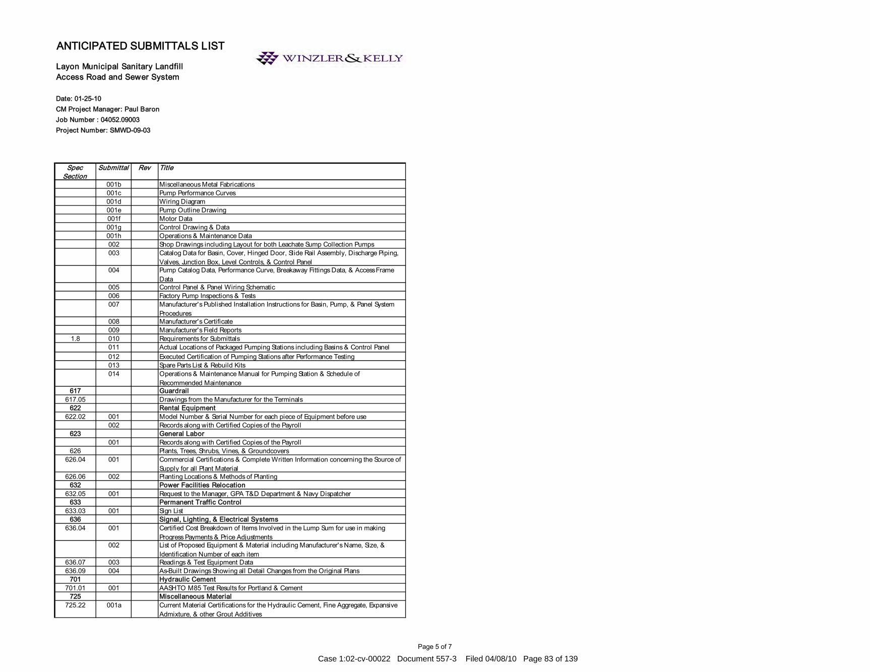
Page 5 of 7
Date: 01-25-10CM Project Manager: Paul BaronJob Number : 04052.09003Project Number: SMWD-09-03
Spec Section
Submittal Rev Title
Layon Municipal Sanitary Landfill Access Road and Sewer System
ANTICIPATED SUBMITTALS LIST
001b Miscellaneous Metal Fabrications001c Pump Performance Curves001d Wiring Diagram001e Pump Outline Drawing001f Motor Data 001g Control Drawing & Data001h Operations & Maintenance Data002 Shop Drawings including Layout for both Leachate Sump Collection Pumps003 Catalog Data for Basin, Cover, Hinged Door, Slide Rail Assembly, Discharge Piping,
Valves, Junction Box, Level Controls, & Control Panel004 Pump Catalog Data, Performance Curve, Breakaway Fittings Data, & Access Frame
Data005 Control Panel & Panel Wiring Schematic006 Factory Pump Inspections & Tests007 Manufacturer's Published Installation Instructions for Basin, Pump, & Panel System
Procedures008 Manufacturer's Certificate009 Manufacturer's Field Reports
1.8 010 Requirements for Submittals011 Actual Locations of Packaged Pumping Stations including Basins & Control Panel012 Executed Certification of Pumping Stations after Performance Testing013 Spare Parts List & Rebuild Kits014 Operations & Maintenance Manual for Pumping Station & Schedule of
Recommended Maintenance617 Guardrail
617.05 Drawings from the Manufacturer for the Terminals622 Rental Equipment
622.02 001 Model Number & Serial Number for each piece of Equipment before use002 Records along with Certified Copies of the Payroll
623 General Labor001 Records along with Certified Copies of the Payroll
626 Plants, Trees, Shrubs, Vines, & Groundcovers626.04 001 Commercial Certifications & Complete Written Information concerning the Source of
Supply for all Plant Material626.06 002 Planting Locations & Methods of Planting
632 Power Facilities Relocation 632.05 001 Request to the Manager, GPA T&D Department & Navy Dispatcher
633 Permanent Traffic Control633.03 001 Sign List
636 Signal, Lighting, & Electrical Systems636.04 001 Certified Cost Breakdown of Items Involved in the Lump Sum for use in making
Progress Payments & Price Adjustments002 List of Proposed Equipment & Material including Manufacturer's Name, Size, &
Identification Number of each item636.07 003 Readings & Test Equipment Data636.09 004 As-Built Drawings Showing all Detail Changes from the Original Plans
701 Hydraulic Cement 701.01 001 AASHTO M85 Test Results for Portland & Cement
725 Miscellaneous Material725.22 001a Current Material Certifications for the Hydraulic Cement, Fine Aggregate, Expansive
Admixture, & other Grout Additives
Case 1:02-cv-00022 Document 557-3 Filed 04/08/10 Page 83 of 139

Page 6 of 7
Date: 01-25-10CM Project Manager: Paul BaronJob Number : 04052.09003Project Number: SMWD-09-03
Spec Section
Submittal Rev Title
Layon Municipal Sanitary Landfill Access Road and Sewer System
ANTICIPATED SUBMITTALS LIST
001b Independent Laboratory Test Results for 1-Day, 3-Day, and 7-Day Strengths, Flow Cone Times, Shrinkage and Expansion Observed, & Time of Initial Set
16302 Underground Transmission & Distribution16302B Basic Electrical Materials & Equipment
2.01 001 Conduits & Fittings2.02 002 Insulated Wire & Cable, Low Voltage2.03 003 Underground Cable 15KV Extruded Insulation with Concentric Nuetral2.00 004 Wire & Cable Identification Tags2.01* 005 Conductor & Cable Terminating Devices2.02* 006 Grounding2.03* 007 Oxide Inhibiting Paste2.04 008 Connectors; 600 Volt Sealed Insulated Underground2.05 009 High Pressure Sodium Luminaires & Mast Arms2.06 010 Transformers: Single Phase, Padmounted, Distribution2.07 011 Transformers: Three Phase, Padmounted, Deadfront Construction Distribution2.08 012 Medium Voltage Cable Joints (Splices)
16302C Underground Electrical Work1.1 Primary Electrical Manhole Shop Drawing
16402 Interior Distribution System2.1 001 Materials & Equipment
2.2.1 002 Rigid Metallic Conduit2.2.2 003 Rigid Nonmetallic Conduit2.2.3 004 Intermediate Metal Conduit2.2.4 005 Electrical Metallic Tubing2.2.5 006 Plastic-Coated Rigid Steel & IMC Conduit2.2.6 007 Flexible Metal Conduit2.2.7 008 Fittings for Metal Conduit, EMT, & Flexible Metal Conduit2.2.8 009 Fittings & Rigid Nonmetallic Conduit2.2.9 010 Liquid-Tight Flexible Nonmetallic Conduit2.3 011 Outlet Boxes & Covers2.4 012 Cabinets, Junction Boxes, & Pull Boxes2.5 013 Wires & Cables2.7 014 Splices & Termination Components2.8 015 Device Plates2.9 016 Switches2.10 017 Receptacles2.11 018 Panelboards2.12 019 Enclosed Circuit Breakers2.13 020 Manual Motor Starters (Motor Rated Switches)2.14 021 Telephone System2.15 022 Community Antenna Television System2.16 023 Grounding & Bonding Equipment2.17 024 Nameplates2.18 025 Wireways
16510 Interior Lighting2.1 001 Fluorescent Lighting Fixtures2.2 002 Incandescent Lighting Fixtures2.3 003 Recess- & Flush-Mounted Fixtures2.4 004 Suspended Fixtures2.5 005 Time Switch2.6 006 Photocell Switch2.7 007 Exit Signs
Case 1:02-cv-00022 Document 557-3 Filed 04/08/10 Page 84 of 139

Page 7 of 7
Date: 01-25-10CM Project Manager: Paul BaronJob Number : 04052.09003Project Number: SMWD-09-03
Spec Section
Submittal Rev Title
Layon Municipal Sanitary Landfill Access Road and Sewer System
ANTICIPATED SUBMITTALS LIST
2.8 008 Emergency Lighting Equipment2.9 009 Support Hangers for Lighting Fixtures in Suspended Ceilings
16520 Exterior Lighting2.2 001 Luminaires2.4 002 Time Switch2.5 003 Photocell Switch2.6 004 Poles2.7 005 Brackets & Supports2.8 006 Pole Foundations
No Spec 15KV Switchgear-Pad MountedNo Spec Pole Mounted TransformersNo Spec Concrete Power Poles - 45'
Case 1:02-cv-00022 Document 557-3 Filed 04/08/10 Page 85 of 139

APPENDIX F
Case 1:02-cv-00022 Document 557-3 Filed 04/08/10 Page 86 of 139

Page 1
CHANGE ORDER REQUEST (PROPOSAL)
Project:
To:
Re:
Change Order Request Number: From (Contractor): Date: A/E Project Number: Contract For:
This Change Order Request (C.O.R.) contains an itemized quotation for changes in the Contract Sum or Contract Time in response to proposed modifications to the Contract Documents based on Proposal Request No. . Description of Proposed Change:
Attached supporting information from: Subcontractor Supplier Reason For Change:
Does Proposed Change involve a change in Contract Sum? No Yes [Increase] [Decrease] $ Does Proposed Change involve a change in Contract Time? No Yes [Increase] [Decrease] days. Attached pages: Proposal Worksheet Summary:
Proposal Worksheet Detail(s): Signed by: Date: Copies: Owner Consultants File
Case 1:02-cv-00022 Document 557-3 Filed 04/08/10 Page 87 of 139

APPENDIX G
Case 1:02-cv-00022 Document 557-3 Filed 04/08/10 Page 88 of 139

DAILY CM REPORT LANDFILL ENTRANCE AREA AND CELLS 1 & 2 PROJECT NO.: SWMD-09-02 LAYON LANDFILL, INARAJAN, GUAM
2 of 7
PAY ITEM PRODUCTION1
ITEM NO.
WORK ELEMENTS UNITS ESTIMATED
DAILY PRODUCTION
ESTIMATED TOTAL TO DATE
PERCENT COMPLETE
(%) COMMENTS
1 Mobilization LS 2 Construction Survey and Staking LS 3 Contractor Sampling and Testing LS 4 Soil Erosion Control LF 5 Water for Dust Control LS 6 Maintenance of Temporary
Access Road LS
7 Clearing & Grubbing SY 8 Entrance Area Earthwork CY 9 Entrance Area Drainage System &
Pipe Culverts LF
10 Administration Building LS 11 Maintenance Shop LS 12 Generator & Pump Building LS 13 Site Parking, AC Pavement,
Compacted Gravel Surface, Curbs, Wheel Stops & Related Facilities
LS
14 Traffic Signs, Markers, Striping LS 15 Sanitary Sewer System & Lift
Stations LS
16 Water System LF 17 Water Storage Tank LS 18 Fuel Storage Tank Pad LS 19 Site Electrical LS 20 Weigh Stations LS 21 Truck Mud Rack LS 22 Equipment Wash Rack / Sediment
Basin LS
23 Oil / Water Separator LS 24 4” Thick Topsoil & Grass Seeding
at Entrance Area SF
25 Leachate Storage Tank and Collection & Pump System
LS 26 Earthwork for Liner Grades LS 27 Cells 1 & 2 Subdrain System
Including Catchment Tank & Road to Tank
LS
28 Cells 1 & 2 Liner & LCRS LS 29 Gas Collector System LS 30 Perimeter Road Extension LS 31 Pond 2 & Drainage Facilities LS 32 Fence & Gates LF 33 Miscellaneous Work LS 34 Field Office LS
1 All pay item quantities are rough estimates by the Field Inspector and are not meant to reflect the exact amount of material installed or moved by the Contractor.
Case 1:02-cv-00022 Document 557-3 Filed 04/08/10 Page 89 of 139
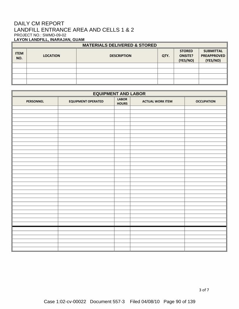
DAILY CM REPORT LANDFILL ENTRANCE AREA AND CELLS 1 & 2 PROJECT NO.: SWMD-09-02 LAYON LANDFILL, INARAJAN, GUAM
3 of 7
MATERIALS DELIVERED & STORED
ITEM NO.
LOCATION DESCRIPTION QTY. STORED ONSITE? (YES/NO)
SUBMITTAL PREAPPROVED
(YES/NO)
EQUIPMENT AND LABOR
PERSONNEL EQUIPMENT OPERATED LABOR HOURS
ACTUAL WORK ITEM OCCUPATION
Case 1:02-cv-00022 Document 557-3 Filed 04/08/10 Page 90 of 139

DAILY CM REPORT LANDFILL ENTRANCE AREA AND CELLS 1 & 2 PROJECT NO.: SWMD-09-02 LAYON LANDFILL, INARAJAN, GUAM
4 of 7
DAILY SUMMARY
ITEM NO. NON‐LINER WORK OBSERVED
ITEM NO. LINER WORK OBSERVED
CONTRACTOR’S QUALITY CONTROL TESTS & RESULTS
ITEM NO. NOTES
CONSTRUCTION MANAGEMENT’S QUALITY ASSURANCE OBSERVATIONS
ITEM NO. NOTES
ON-SITE MEETINGS
ITEM NO. NOTES
COMMENTS
Case 1:02-cv-00022 Document 557-3 Filed 04/08/10 Page 91 of 139

DAILY CM REPORT LANDFILL ENTRANCE AREA AND CELLS 1 & 2 PROJECT NO.: SWMD-09-02 LAYON LANDFILL, INARAJAN, GUAM
5 of 7
(Causes for delays; Verbal Instructions Given to Contractor – Including Names, Reactions and Remarks; Developments that may lead to a change order or finding of fact):
Paul Baron, PE Construction Manager Date: February 24, 2010
Case 1:02-cv-00022 Document 557-3 Filed 04/08/10 Page 92 of 139
DAILY PHOTO DOCUMENTATION LANDFILL ENTRANCE AREA AND CELLS 1 & 2 PROJECT NO.: SWMD-09-02 LAYON LANDFILL, INARAJAN, GUAM
6 of 7
Photos
Case 1:02-cv-00022 Document 557-3 Filed 04/08/10 Page 93 of 139

DAILY PHOTO DOCUMENTATION LANDFILL ENTRANCE AREA AND CELLS 1 & 2 PROJECT NO.: SWMD-09-02 LAYON LANDFILL, INARAJAN, GUAM
7 of 7
Photo Maps
Case 1:02-cv-00022 Document 557-3 Filed 04/08/10 Page 94 of 139
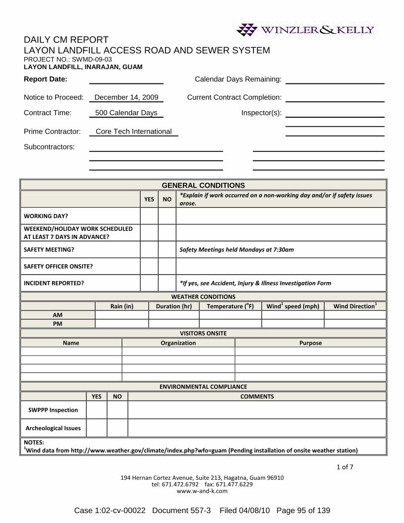
DAILY CM REPORT LAYON LANDFILL ACCESS ROAD AND SEWER SYSTEM PROJECT NO.: SWMD-09-03 LAYON LANDFILL, INARAJAN, GUAM
1 of 7
194 Hernan Cortez Avenue, Suite 213, Hagatna, Guam 96910 tel: 671.472.6792 fax: 671.477.6229
www.w-and-k.com
Report Date: Calendar Days Remaining:
Notice to Proceed: December 14, 2009 Current Contract Completion: Contract Time: 500 Calendar Days Inspector(s): Prime Contractor: Core Tech International Subcontractors:
GENERAL CONDITIONS
YES NO *Explain if work occurred on a non-working day and/or if safety issues arose.
WORKING DAY?
WEEKEND/HOLIDAY WORK SCHEDULED AT LEAST 7 DAYS IN ADVANCE?
SAFETY MEETING? Safety Meetings held Mondays at 7:30am
SAFETY OFFICER ONSITE?
INCIDENT REPORTED? *If yes, see Accident, Injury & Illness Investigation Form
WEATHER CONDITIONS
Rain (in) Duration (hr) Temperature (oF) Wind1 speed (mph) Wind Direction1 AM PM
VISITORS ONSITE
Name Organization Purpose
ENVIRONMENTAL COMPLIANCE
YES NO COMMENTS
SWPPP Inspection
Archeological Issues
NOTES: 1Wind data from http://www.weather.gov/climate/index.php?wfo=guam (Pending installation of onsite weather station)
Case 1:02-cv-00022 Document 557-3 Filed 04/08/10 Page 95 of 139

DAILY CM REPORT LAYON SANITARY LANDFILL ACCESS ROAD AND SEWER SYSTEM PROJECT NO.: SWMD-09-03 LAYON LANDFILL, INARAJAN, GUAM
2 of 7
PAY ITEM PRODUCTION1
ITEM NO.
WORK ELEMENTS UNIT ESTIMATED
DAILY PRODUCTION
ESTIMATED TOTAL TO
DATE
PERCENT COMPLETE
(%) COMMENTS
15101 Mobilization LS 15201 Construction Survey and Staking LF 15401 Contractor Sampling and Testing LS 15701 Soil Erosion Control LF 15801 Watering for Dust Control LS 20101 Clearing & Grubbing LF
20301 Removal of Structures and
Obstructions LS
20401 Roadway Excavation LF
20701 Geotextile Filter Fabric (Toe
Protection) LS
30101 Aggregate Base, Grading C LF 30102 Subbase, Grading B LF 40301 Asphalt Concrete Pavement LF
40501 Hot Asphalt Concrete Friction
Course, 1-inch LF
60101 Concrete Headwall LS 60201 Culverts LF 60401 Catch Basin LF 60501 Percolation Drainage Chamber LS
60801 Paved Waterways, Concrete (Cut-
Off Ditch) LS
60802 Paved Waterway, Riprap, Class I
(Toe Protection) LS
60803 Construct Overside Drains (OSD) LS 60901 Curb, Asphalt, 6-inch Depth LF 61101 Water System LF 61201 Sanitary Sewer System LF
612A01 Sanitary Sewer Lift Station LS 61701 Guard Rail, Type W LF 62101 Preserve GGN Monuments LS
62501 Turf Reinforcement Material
(TRM) LS
62502 Turf Establishment LS 63301 Permanent Traffic Control LS 63401 Permanent Pavement Markings LS 63501 Temporary Traffic Control LS
636A01
Electrical System Including Standby Generators and
Enclosures for Sanitary Sewer Lift Stations
LS
63701 Field Offices LS 1All pay item quantities are rough estimates by the Field Inspector and are not meant to reflect the exact amount of material installed or moved by the Contractor.
Case 1:02-cv-00022 Document 557-3 Filed 04/08/10 Page 96 of 139

DAILY CM REPORT LAYON SANITARY LANDFILL ACCESS ROAD AND SEWER SYSTEM PROJECT NO.: SWMD-09-03 LAYON LANDFILL, INARAJAN, GUAM
3 of 7
MATERIALS DELIVERED & STORED
ITEM NO.
LOCATION DESCRIPTION QTY. STORED ONSITE? (YES/NO)
SUBMITTAL PREAPPROVED
(YES/NO)
EQUIPMENT AND LABOR
PERSONNEL EQUIPMENT LABOR HOURS
ACTUAL WORK ITEM OCCUPATION
Case 1:02-cv-00022 Document 557-3 Filed 04/08/10 Page 97 of 139
DAILY CM REPORT LAYON SANITARY LANDFILL ACCESS ROAD AND SEWER SYSTEM PROJECT NO.: SWMD-09-03 LAYON LANDFILL, INARAJAN, GUAM
4 of 7
DAILY SUMMARY
ITEM NO. WORK OBSERVED
CONTRACTOR’S QUALITY CONTROL TESTS & RESULTS
ITEM NO. NOTES
CONSTRUCTION MANAGEMENT’S QUALITY ASSURANCE OBSERVATIONS
ITEM NO. NOTES
ON-SITE MEETINGS
ITEM NO. NOTES
Case 1:02-cv-00022 Document 557-3 Filed 04/08/10 Page 98 of 139

DAILY CM REPORT LAYON SANITARY LANDFILL ACCESS ROAD AND SEWER SYSTEM PROJECT NO.: SWMD-09-03 LAYON LANDFILL, INARAJAN, GUAM
5 of 7
COMMENTS
(Causes for delays; Verbal Instructions Given to Contractor – Including Names, Reactions and Remarks; Developments that may lead to a change order or finding of fact):
Paul Baron, PE Construction Manager Date: February 24, 2010
Case 1:02-cv-00022 Document 557-3 Filed 04/08/10 Page 99 of 139

DAILY PHOTO DOCUMENTATION LAYON SANITARY LANDFILL ACCESS ROAD AND SEWER SYSTEM PROJECT NO.: SWMD-09-03 LAYON LANDFILL, INARAJAN, GUAM
6 of 7
Photos
Case 1:02-cv-00022 Document 557-3 Filed 04/08/10 Page 100 of 139

DAILY PHOTO DOCUMENTATION LAYON SANITARY LANDFILL ACCESS ROAD AND SEWER SYSTEM PROJECT NO.: SWMD-09-03 LAYON LANDFILL, INARAJAN, GUAM
7 of 7
Photo Maps
Case 1:02-cv-00022 Document 557-3 Filed 04/08/10 Page 101 of 139

DAILY FIELD OBSERVATION REPORT
Project: Owner: Prime Contractor:
Report Number: Date: Time: A/E Project Number:
Weather Site Conditions Day
Clear Warm Clear Dusty Monday Thursday Overcast Hot Muddy Tuesday Friday Rain Temperature Range Wednesday
Materials Delivered:
Task No. Work Observed:
Case 1:02-cv-00022 Document 557-3 Filed 04/08/10 Page 102 of 139

Task No. Equipment: Staff Position: Hours Worked:
Remarks Nonconforming Work Reported this Date to Contractor:
Site Visitors and Testing:
Remarks:
Attachments: Signed by: Date: Copies: Owner A/E Contractor Consultants File
Case 1:02-cv-00022 Document 557-3 Filed 04/08/10 Page 103 of 139

Page 1
ON-SITE MEETING MINUTES Project:
Owner: Re:
Project Number: SWMD-09-0 A/E Project Number: Meeting Location: Onsite Meeting Date: Time:
This confirms and records our interpretation of the discussions which occurred and our understanding reached during this meeting. Unless notified in writing within seven days of the date below, we will assume that the following interpretation or description is complete and accurate. Participants:
Item Description Action By 1
Attachments Prepared by: Paul Baron Date: Copies: Participants GBB File
Case 1:02-cv-00022 Document 557-3 Filed 04/08/10 Page 104 of 139

Layon Landfill Date Issued: Month XX, 2010 Entrance Area & Cells 1&2 Weekly Construction Mtg. XXX Minutes Page 1 of 2
194 Hernan Cortez Ave. Ste. 213, Terlaje Bldg. Hagatna, Guam 96910 Tel. No. (671) 472-6792 Fax No. (671) 477-6229 Email: [email protected]
Draft Weekly Construction Meeting Minutes X.X: XX/XX/10
Project: Layon Landfill Entrance Area & Cells 1&2 Project No. SWMD-09-02, W&K Job #0405209002 Meeting No.: XX Meeting Date: XX/XX/10, 10:00 am – 11:30 am Location: Black Construction trailer Distribution list: All Attendees _________________________________________________________________________ These meeting minutes summarize the meeting on Tuesday Month XX, 2010 between GBB (Contracting Officer), W&K (Construction Manager), and BCC (Contractor) for the above-referenced project. Those in attendance are noted below. Attendees
Paul Baron (PB) Winzler & Kelly (W&K) Organization
Aaron Sutton (AS) W&K Antonia Meno (AM) W&K Jose Armenta (JA) Vector Engineering Inc. (VEI) Tom Anderson (TA) Black Construction (BCC) Willie Diwa (WD) BCC Augie De Leon (AD) BCC Dante Abucay (DA) BCC Alice Valencia (AV) BCC Johnny Sol (JS) BCC Leonard Rabago (LR) BCC Orly Nojadera (ON) BCC
Attendees by Phone Chris Lund (CL) Gershman Brinker & Bratton (GBB)
Organization
Jeff Larioni (JL) GBB Scott Purdy (SP) VEI
Item No.
Description Status Start Due RP
1 Health and Safety
Case 1:02-cv-00022 Document 557-3 Filed 04/08/10 Page 105 of 139

Layon Landfill Date Issued: Month XX, 2010 Entrance Area & Cells 1&2 Weekly Construction Mtg. XXX Minutes Page 2 of 2
NTP DATE: 12/30/09 ORIGINAL CONTRACT CALENDAR DAYS: 500 APPROVED TIME EXTENSION CALENDAR DAYS 0 CONTRACT CALENDAR DAYS EXPIRED AS OF 2/16/10 XX APPROX. NON WORKING DAYS PROVIDED FOR IN CONTRACT TO DATE: X
CALENDAR DAYS REMAINING IN PROJECT: XXX NON WORKING DAYS DUE TO INCLEMENT WEATHER TO DATE: 0
Next meeting will be held at Black Construction on-site office on Tuesday, Month XX starting at 10:00 am. These meeting minutes constitute the official record of the items discussed, and were issued in draft form and (will be) amended based on comments received and shall stand as written. These meeting minutes were prepared by Paul Baron of Winzler & Kelly.
________________________ Paul Baron Winzler & Kelly
Item No.
Description Status Start Due RP
2 Project Administration 3 Site Access & Security Control 4 General Discussion and Construction Related Issues 5 Project Cost Tracking 6 Environmental Compliance 7 Submittals 8 RFI’s 9 Schedules 10 Items Received
Case 1:02-cv-00022 Document 557-3 Filed 04/08/10 Page 106 of 139

Layon Landfill Date Issued: Month XX, 2010 Access Road and Sewer Weekly Construction Mtg. #XXX Minutes Page 1 of 2
194 Hernan Cortez Ave. Ste. 213, Terlaje Bldg. Hagatna, Guam 96910 Tel. No. (671) 472-6792 Fax No. (671) 477-6229 Email: [email protected]
Draft Weekly Construction Meeting Minutes XX: XX/XX/10
Project: Layon Landfill Access Road & Sewer Systems Project No. SWMD-09-03, W&K Job #0405209002 Meeting No.: XX Meeting Date: XX/XX/10, 9:00 am – 10:30 am Location: CTI trailer Distribution list: All Attendees _________________________________________________________________________ These meeting minutes summarize the meeting on Wednesday Month XX, 2010 between GBB (Contracting Officer), W&K (Construction Manager), and CTI (Contractor) for the above-referenced project. Those in attendance are noted below. Attendees
Paul Baron (PKB) Winzler & Kelly (W&K) Organization
Aaron Sutton (AS) (W&K) Antonia Meno (AM) W&K BrianKeith Espiritu (BE) W&K Jose Armenta (JA) Vector Engineering Roberto Lee (RL) Core Tech International (CTI) Pepito Bedia (PB) CTI Irwin Liwag (IL) CTI Joel Santos (JS) CTI Roel Lugue (RL2) CTI
Attendees by Phone Jeff Larioni (JL) Gershman Brinker & Bratton (GBB)
Organization
Item No.
Description Status Start Due RP
1 Health and Safety 2 Project Administration 3 Site Access & Security Control 4 General Discussion and Construction Related Issues 5 Project Cost Tracking 6 Environmental Compliance 7 Submittals 8 RFI’s 9 Schedules 10 Items Received
Case 1:02-cv-00022 Document 557-3 Filed 04/08/10 Page 107 of 139

Layon Landfill Date Issued: Month XX, 2010 Access Road and Sewer Weekly Construction Mtg. #XXX Minutes Page 2 of 2
NTP DATE: 12/14/09 ORIGINAL CONTRACT CALENDAR DAYS: 500 APPROVED TIME EXTENSION CALENDAR DAYS 0 CONTRACT CALENDAR DAYS EXPIRED AS OF YESTERDAY XX NON WORKING DAYS PROVIDED FOR IN CONTRACT TO DATE: X
CALENDAR DAYS REMAINING IN PROJECT: XXX NON WORKING DAYS DUE TO INCLEMENT WEATHER TO DATE: 0
Next meeting will be held at Core Tech trailer on Wednesday, Month XX starting at 9:00am. These meeting minutes constitute the official record of the items discussed and were issued in draft form and shall stand as written unless amended based on comments received within 7 calendar days of issuance. These meeting minutes were prepared by Paul Baron of Winzler & Kelly.
________________________
Paul Baron, Sr. Project Manager
Case 1:02-cv-00022 Document 557-3 Filed 04/08/10 Page 108 of 139

Page 1
COMMUNICATION RECORD
Project: Layon Landfill Access Road and Sewer Systems
To:
From: Re:
Date: Project Number: SWMD-09-03
Letter Dated:
Fax Dated:
Telephone Call Dated:
Personal Contact Dated: Contact:
This confirms and records our interpretation of the understanding reached concerning matters indicated. Unless notified in writing within seven days of the date below, we will assume that the following interpretation or description is complete and accurate.
Attachments Signed by: Date: Copies: GBB CTI EOR Contact File
Case 1:02-cv-00022 Document 557-3 Filed 04/08/10 Page 109 of 139

© Copyright 2007, Construction Specifications Institute, 99 Canal Center Plaza, Suite 300, Alexandria, VA 22314
Page 1 Form Version: July 1994
This is not an official CSI Construction Contract Administration (CCA) Form. Please use CSI's official CCA Forms if required by your project needs.
COMMUNICATION LOG
Project: Layon Landfill Access Road and Sewer System Owner: GBB/DPW SWMD
Project Number: SWMD-09-03 Contractor: Core Tech International
DATE
TIME
PERSON INITIATING CALL
PERSON CALLED
BRIEF SUMMARY OF CONVERSATION
Case 1:02-cv-00022 Document 557-3 Filed 04/08/10 Page 110 of 139

SWMD-09-02 LAYON LANDFILL – Entrance Area Facilities and Cells 1 & 2 - RFI Transmittal Sheet
Contractor: Black Construction Corp.
P.O. Box 24667 GMF GU 96921
Specification Section/Description RFI
No. Date
Attachments:
Transmittal Record Attention Date Sent Date Received Date Due Initials of Receiver
Contractor to CM
CM to EOR
EOR to CM
CM to GBB
GBB to CM
CM to Contractor
Contractor RFI Comments: EOR Response Comments: CM Response Comments: Notes: 1). This review is only for general conformance with the design concept and the information given in this construction documents. Corrections or comments made on the submittals or shop drawings during this review do not relieve the contractor from compliance with the requirements of the construction documents, including without limitation, the plans and specifications. Review of a specific item shall not include review of an assembly of which the item is a component. The contractor is responsible for: Dimensions to be confirmed and correlated at the jobsite; information that pertains solely to the fabrication processes or to the means, methods, techniques, sequences and procedures of construction; coordination of the work with that of all other trades, and; performing all work in a safe and satisfactory manner. This review is subject to all provisions of the Contract Documents. 2). Notations do not authorize changes to contract sum or time. If the Contractor is authorized to proceed with the work identified in this submittal, it is assumed that no change in the contract amount or completion date is required. If a change in the work due to comments from this submittal review will affect the contract amount or completion date, notify the CM prior to proceeding.
Case 1:02-cv-00022 Document 557-3 Filed 04/08/10 Page 111 of 139

SWMD-09-03 LAYON LANDFILL – Access Road & Sewer Systems - RFI Cover Sheet
Contractor: Core Tech International
500 Mariner Avenue Barrigada, Guam 96913
Specification Section/Description RFI
No. Date
Attachments:
Transmittal Record Attention Date Sent Date Received Date Due Initials of Receiver
Contractor to CM
CM to EOR
EOR to CM
CM to GBB
GBB to CM
CM to Contractor
Contractor RFI Comments: EOR Response Comments: CM Response Comments: Notes: 1). This review is only for general conformance with the design concept and the information given in this construction documents. Corrections or comments made on the submittals or shop drawings during this review do not relieve the contractor from compliance with the requirements of the construction documents, including without limitation, the plans and specifications. Review of a specific item shall not include review of an assembly of which the item is a component. The contractor is responsible for: Dimensions to be confirmed and correlated at the jobsite; information that pertains solely to the fabrication processes or to the means, methods, techniques, sequences and procedures of construction; coordination of the work with that of all other trades, and; performing all work in a safe and satisfactory manner. This review is subject to all provisions of the Contract Documents. 2). Notations do not authorize changes to contract sum or time. If the Contractor is authorized to proceed with the work identified in this submittal, it is assumed that no change in the contract amount or completion date is required. If a change in the work due to comments from this submittal review will affect the contract amount or completion date, notify the CM prior to proceeding.
Case 1:02-cv-00022 Document 557-3 Filed 04/08/10 Page 112 of 139

Page 1 of 1
Date:1 CM Project Manager: Paul Baron2 Job Number : 04052.090023 Project Number: SMWD-09-02
No.Date Received Information Requested
Drawing Ref. Spec. Ref. Response Date Status
Cancelled
Status code:
RFI CONTROL LOG
Layon Municipal Sanitary Landfill Entrance Area and Facilities and Cells #1 and #2
Response ReceivedResponse Pending
Case 1:02-cv-00022 Document 557-3 Filed 04/08/10 Page 113 of 139

LAYON LANDFILL – Entrance Area Facilities and Cells 1 & 2 Submittal Form
Contractor: Black Construction Corp.
P.O. Box 24667 GMF GU 96921
Specification Section/Description Submittal
No. Revision
No.
Submitted for Review: Y/N Meets Specification: Y/N Reviewed by Contractor: __________________ Initials of Contractor
Transmittal Record Attention Date
Sent Date
Received Date Due
Quantity Initials of
Receiver Reproducibles Prints Manufacturer’s Literature Samples
Contractor to CM
CM to EOR
EOR to CM
CM to Contractor
Item #
Submittal Review Status
Dwg/ Item Dated
Spec/ Drawing
Reference #
Description 1
Reviewed/ No Exceptions
Taken
2 Make
Corrections Noted
3 Amend as Noted and Resubmit
4 Rejected/ Resubmit
EOR CM EOR CM EOR CM EOR CM
1
2
3
4
EOR Comments: CM Comments: Notes: 1). This review is only for general conformance with the design concept and the information given in this construction documents. Corrections or comments made on the submittals or shop drawings during this review do not relieve the contractor from compliance with the requirements of the construction documents, including without limitation, the plans and specifications. Review of a specific item shall not include review of an assembly of which the item is a component. The contractor is responsible for: Dimensions to be confirmed and correlated at the jobsite; information that pertains solely to the fabrication processes or to the means, methods, techniques, sequences and procedures of construction; coordination of the work with that of all other trades, and; performing all work in a safe and satisfactory manner. This review is subject to all provisions of the Contract Documents. 2). Notations do not authorize changes to contract sum or time. If the Contractor is authorized to proceed with the work identified in this submittal, it is assumed that no change in the contract amount or completion date is required. If a change in the work due to comments from this submittal review will affect the contract amount or completion date, notify the CM prior to proceeding.
Case 1:02-cv-00022 Document 557-3 Filed 04/08/10 Page 114 of 139
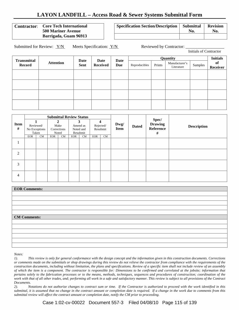
LAYON LANDFILL – Access Road & Sewer Systems Submittal Form
Contractor: Core Tech International
500 Mariner Avenue Barrigada, Guam 96913
Specification Section/Description Submittal
No. Revision
No.
Submitted for Review: Y/N Meets Specification: Y/N Reviewed by Contractor: __________________ Initials of Contractor
Transmittal Record Attention Date
Sent Date
Received Date Due
Quantity Initials of
Receiver Reproducibles Prints Manufacturer’s Literature Samples
Item #
Submittal Review Status
Dwg/ Item Dated
Spec/ Drawing
Reference #
Description 1
Reviewed/ No Exceptions
Taken
2 Make
Corrections Noted
3 Amend as Noted and Resubmit
4 Rejected/ Resubmit
EOR CM EOR CM EOR CM EOR CM
1
2
3
4
EOR Comments: CM Comments: Notes: 1). This review is only for general conformance with the design concept and the information given in this construction documents. Corrections or comments made on the submittals or shop drawings during this review do not relieve the contractor from compliance with the requirements of the construction documents, including without limitation, the plans and specifications. Review of a specific item shall not include review of an assembly of which the item is a component. The contractor is responsible for: Dimensions to be confirmed and correlated at the jobsite; information that pertains solely to the fabrication processes or to the means, methods, techniques, sequences and procedures of construction; coordination of the work with that of all other trades, and; performing all work in a safe and satisfactory manner. This review is subject to all provisions of the Contract Documents. 2). Notations do not authorize changes to contract sum or time. If the Contractor is authorized to proceed with the work identified in this submittal, it is assumed that no change in the contract amount or completion date is required. If a change in the work due to comments from this submittal review will affect the contract amount or completion date, notify the CM prior to proceeding.
Case 1:02-cv-00022 Document 557-3 Filed 04/08/10 Page 115 of 139
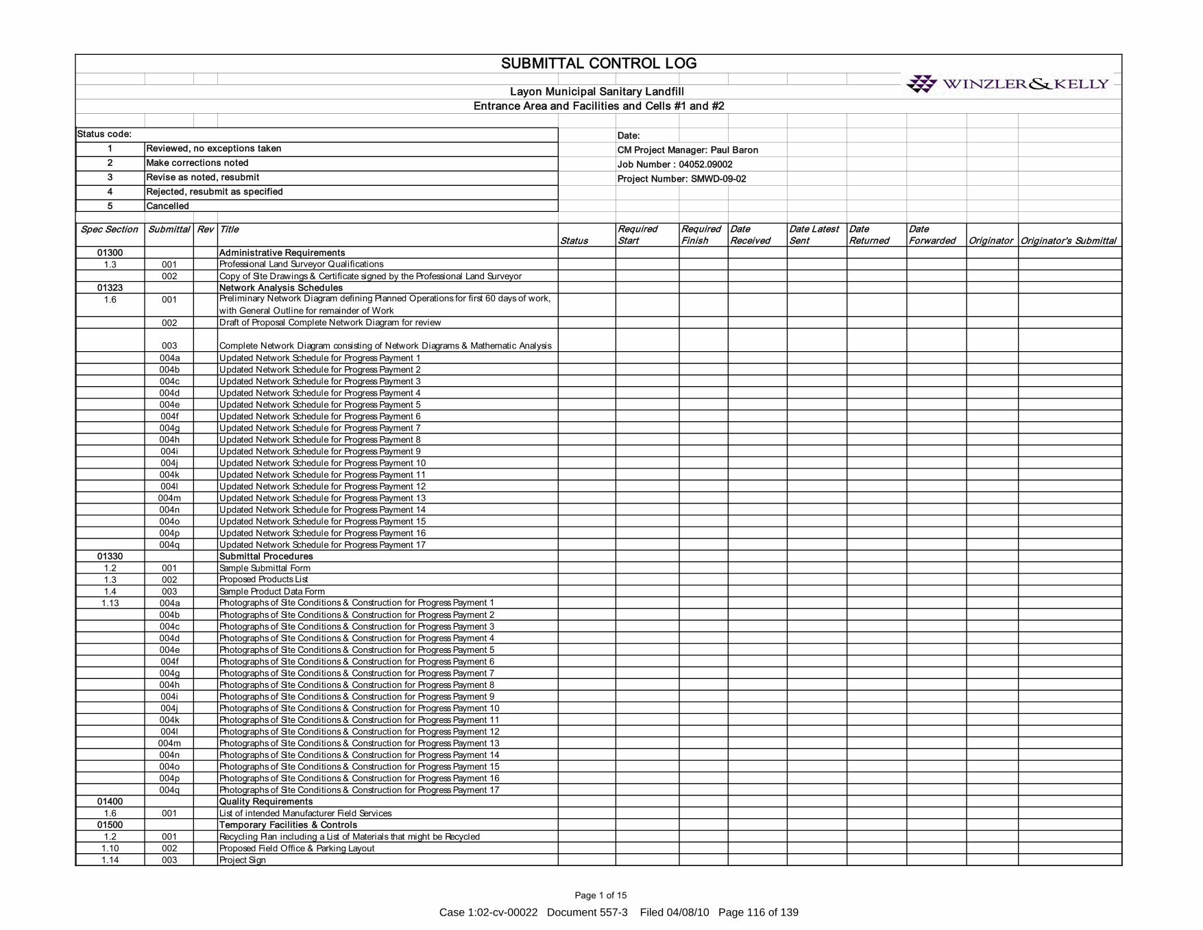
Page 1 of 15
Date:1 CM Project Manager: Paul Baron2 Job Number : 04052.090023 Project Number: SMWD-09-0245
Spec Section Submittal Rev TitleStatus
Required Start
Required Finish
Date Received
Date Latest Sent
Date Returned
Date Forwarded Originator Originator's Submittal
01300 Administrative Requirements1.3 001 Professional Land Surveyor Qualifications
002 Copy of Site Drawings & Certificate signed by the Professional Land Surveyor01323 Network Analysis Schedules
1.6 001 Preliminary Network Diagram defining Planned Operations for first 60 days of work, with General Outline for remainder of Work
002 Draft of Proposal Complete Network Diagram for review
003 Complete Network Diagram consisting of Network Diagrams & Mathematic Analysis004a Updated Network Schedule for Progress Payment 1004b Updated Network Schedule for Progress Payment 2004c Updated Network Schedule for Progress Payment 3004d Updated Network Schedule for Progress Payment 4004e Updated Network Schedule for Progress Payment 5004f Updated Network Schedule for Progress Payment 6004g Updated Network Schedule for Progress Payment 7004h Updated Network Schedule for Progress Payment 8004i Updated Network Schedule for Progress Payment 9004j Updated Network Schedule for Progress Payment 10004k Updated Network Schedule for Progress Payment 11004l Updated Network Schedule for Progress Payment 12
004m Updated Network Schedule for Progress Payment 13004n Updated Network Schedule for Progress Payment 14004o Updated Network Schedule for Progress Payment 15004p Updated Network Schedule for Progress Payment 16004q Updated Network Schedule for Progress Payment 17
01330 Submittal Procedures1.2 001 Sample Submittal Form1.3 002 Proposed Products List1.4 003 Sample Product Data Form
1.13 004a Photographs of Site Conditions & Construction for Progress Payment 1004b Photographs of Site Conditions & Construction for Progress Payment 2004c Photographs of Site Conditions & Construction for Progress Payment 3004d Photographs of Site Conditions & Construction for Progress Payment 4004e Photographs of Site Conditions & Construction for Progress Payment 5004f Photographs of Site Conditions & Construction for Progress Payment 6004g Photographs of Site Conditions & Construction for Progress Payment 7004h Photographs of Site Conditions & Construction for Progress Payment 8004i Photographs of Site Conditions & Construction for Progress Payment 9004j Photographs of Site Conditions & Construction for Progress Payment 10004k Photographs of Site Conditions & Construction for Progress Payment 11004l Photographs of Site Conditions & Construction for Progress Payment 12
004m Photographs of Site Conditions & Construction for Progress Payment 13004n Photographs of Site Conditions & Construction for Progress Payment 14004o Photographs of Site Conditions & Construction for Progress Payment 15004p Photographs of Site Conditions & Construction for Progress Payment 16004q Photographs of Site Conditions & Construction for Progress Payment 17
01400 Quality Requirements 1.6 001 List of intended Manufacturer Field Services
01500 Temporary Facilities & Controls 1.2 001 Recycling Plan including a List of Materials that might be Recycled
1.10 002 Proposed Field Office & Parking Layout1.14 003 Project Sign
Rejected, resubmit as specifiedCancelled
SUBMITTAL CONTROL LOG
Layon Municipal Sanitary Landfill Entrance Area and Facilities and Cells #1 and #2
Reviewed, no exceptions takenMake corrections notedRevise as noted, resubmit
Status code:
Case 1:02-cv-00022 Document 557-3 Filed 04/08/10 Page 116 of 139

Page 2 of 15
Date:1 CM Project Manager: Paul Baron2 Job Number : 04052.090023 Project Number: SMWD-09-0245
Spec Section Submittal Rev TitleStatus
Required Start
Required Finish
Date Received
Date Latest Sent
Date Returned
Date Forwarded Originator Originator's Submittal
Rejected, resubmit as specifiedCancelled
SUBMITTAL CONTROL LOG
Layon Municipal Sanitary Landfill Entrance Area and Facilities and Cells #1 and #2
Reviewed, no exceptions takenMake corrections notedRevise as noted, resubmit
Status code:
1.17 004 Qualifications for Fire Prevention & Protection Responsible Person1.18 005 Security Program1.19 006 Water Control Plan1.20 007 Dust Control Plan1.21 008 Erosion & Sediment Plan1.22 009 Noise Control Plan1.23 010 Pest Control Plan1.24 011 Pollution Control Plan1.25 012 Rodent Control Plan
01700 Execution Requirements1.3 001 Written Report that Equipment or System has been Properly Installed & Functioning
Properly1.7 002
Project Record Documents & Actual Revisions to the Work (Review Monthly w/PP)1.8 003 Operation & Maintenance Instructions1.9 004 Three Copies of Preliminary Drafts of Manual for Materials & Finishes before Start of
Work005 One Completed Volume 15 days prior to Final Inspection006
Two Sets of Revised Final Volumes in Final Form within 10 days after Final Inspection1.10 007 Three Copies of Preliminary Drafts of Manual for Equipment & Systems
008 One Completed Volume 15 days prior to Final Inspection009
Two Sets of Revised Final Volumes in Final Form within 10 days after Final Inspection1.12 010 Product Warranties & Bonds prior to Final Application for Payment
01770 Project Close Out3.1 001 Project Record Drawings to be submitted before Final Inspection Request
002 Product Warranties & Bonds prior to Final Inspection Request3.2 003 Written Certification that Project is Substantially Complete
004 List of Deficiencies to be Corrected before Final Acceptance3.3 005 Letter of Acceptance
02055 Soils 1.4 001 Test Data for Controlled Fill & Select Fill
02060 Aggregate1.4 001 Name of Imported Fill Material Suppliers & Test Data
02225 Low Permeability Soil Liner1.4 001 Information & Test Results for Proposed Soil Material
002 Work Plan for the Test Pad & Method of Mixing & Constructing the Low Permeability Soil Liner
2.1 003a Moisture Content Test Results003b Particle Size Test Results003c Atterberg Limits003d Laboratory Compaction Test Results003e Laboratory Hydraulic Conductivity at a Specified Compaction
02230 Site Clearing1.2 001 Product Data for Herbicide
02240 Gravel Drainage Media1.4 001 Results of Conformance Tests
02250 Protective Soil Cover 1.4 001 Source Evaluation Tests Results
02320 Backfill1.3
001Materials Source including Name of Imported Fill Materials Suppliers & Test Data
Case 1:02-cv-00022 Document 557-3 Filed 04/08/10 Page 117 of 139

Page 3 of 15
Date:1 CM Project Manager: Paul Baron2 Job Number : 04052.090023 Project Number: SMWD-09-0245
Spec Section Submittal Rev TitleStatus
Required Start
Required Finish
Date Received
Date Latest Sent
Date Returned
Date Forwarded Originator Originator's Submittal
Rejected, resubmit as specifiedCancelled
SUBMITTAL CONTROL LOG
Layon Municipal Sanitary Landfill Entrance Area and Facilities and Cells #1 and #2
Reviewed, no exceptions takenMake corrections notedRevise as noted, resubmit
Status code:
002 Manufacturer's Certificate02324 Termite Control
1.3 001 Product Data on Toxicants to be used, Composition by Percentage, Dilution Schedule, Intended Application Rate (Include Product Label Information)
002 Test Reports003 Manufacturer's Application Instructions 004 Manufacturer's Certificate
1.4 005 Project Record Documents006 Operation & Maintenance Data
02512 Site Water Distribution1.4 001 Product Data on Pipe Materials, Pipe Fittings, Valves, & Accessories1.5 002 Project Record Documents
003 Identify & Describe Discovery of Uncharted Utilities02532 Wastewater Pumping Stations (Leachate Only)
1.7 001a Guide Rail System001b Miscellaneous Metal Fabrications001c Pump Performance Curves001d Wiring Diagrams001e Pump Outline Drawing001f Motor Data001g Control Drawing & Data001h Operations & Maintenance Data002 Shop Drawings indicating Layout for all Leachate Sump Collection Pumps003 Product Data004 Test Reports005 Manufacturer's Installation Instructions006 Manufacturer's Certificate007 Manufacturer's Field Reports008 Start-up Report before Final Acceptance of Pumps
1.8 009 Execution Requirements010 Record of Actual Locations of Packaged Pumping Stations011 Executed Certification of Pumping Stating After Performance Testing 012 Spare Parts List & Rebuild Kits 013 Operations & Maintenance Manuals
02536001 Certificate of Compliance 002 Proposed Equipment and Methods003 Manufacturers Installation Instructions 004 Manufacturer's Certificate
02538 Sanitary System 1.5 001 Product Data indicating Pipe Material Used & Pipe Accessories
02577 Pavement Markings1.4 001 Manufacturer's Printed Product Data Sheets
02610 Pipe Culverts 1.3 001 Product Data on Pipe, Fittings, & Accessories1.4 002 Project Recorded Documents indicating Actual Location of Pipe Runs, Connections,
& Invert Elevations02630 Storm Drainage
1.3 001 Product Data indicating Pipe, Pipe Accessories, & Catch Basins & Grates002 Manufacturer's Installation Instructions
1.4 003 Project Recorded Documents indicating Actual Location of Pipe Runs, Connections, Catch Basins, Cleanouts, & Invert Elevations
02640 Slope Protection Rock
Case 1:02-cv-00022 Document 557-3 Filed 04/08/10 Page 118 of 139

Page 4 of 15
Date:1 CM Project Manager: Paul Baron2 Job Number : 04052.090023 Project Number: SMWD-09-0245
Spec Section Submittal Rev TitleStatus
Required Start
Required Finish
Date Received
Date Latest Sent
Date Returned
Date Forwarded Originator Originator's Submittal
Rejected, resubmit as specifiedCancelled
SUBMITTAL CONTROL LOG
Layon Municipal Sanitary Landfill Entrance Area and Facilities and Cells #1 and #2
Reviewed, no exceptions takenMake corrections notedRevise as noted, resubmit
Status code:
1.4.1 001 Source Evaluation Tests Results of Slope Protection Rock to be Supplied1.4.2 002a Reports on Quality Control Tests conducted by the Manufacturer1.4.2 002b
Specification for Geotextile including All Properties published by the Manufacturer1.4.2 002c
Written Certification that Manufacturer inspected Geotextile to be Needle-Free1.4.2 002d Written Quality Control Certificates including Roll ID Numbers, Testing Procedures &
Results of Quality Control Tests1.4.3 003 Concrete Materials Information & a Concrete Mix Design
02721 Aggregate Base Course1.3 001 Materials Source: Name of Imported Materials Suppliers & Test Data
02725 Polyethylene Landfill Pipe1.4 001 Geosynthetics CQA Certificates of Compliance for Pipe Materials & Fittings
002 Proposal for Equipment & Methods to be used for Welding Pipe02730 Leachate Collection Riser Assembly
1.4 001 Certificates of Compliance for all Components of Assembly002 Shop Drawings of Assembly prior to Fabrication or Installation
02735 Landfill Gas System Components 1.4 001a Specifications & Manufacturer's Data for HDPE Pipe & Fittings
001b Specifications & Manufacturer's Data for PVC Pipe & Fittings001c Specifications & Manufacturer's Data for Valves001d Specifications & Manufacturer's Data for Condensate Sumps/Pump Stations
02740 Flexible Pavement1.5 001 Product Information & Mix Design
002 Manufacturer's Certificate02750 Rigid Pavement
1.3 001 Product Data on Joint Filler, Admixtures, & Curing Compounds02751 Geomembrane
1.4 001 Dated QC Certificates from resin supplierWritten Certification that Min Values in Specs guaranteed by ManufacturerQC Certificates from AGRU AmericaResin Supplier's name & Plant LocationsManufacturer's Test ResultsList of Materials which comprises GeomembraneQC Manual for Field Installation of GeomembraneManufacturer's Proposed Panel Layout Drawing
Manufacturer's Qualifications as Geosynthetic Liner Installer (Including History of Manufacturer, Resume of Key Personnel, & List of Master Seamers & QC Technicians
02752 Geotextiles1.4 002 Manufacturing QC Test Results
SKAPS GE-116 16oz. Non-Woven Geotextile Property SheetSKAPS Industries' Manufacturing QC Program Outline & Certifications
Written QC Certificates signed by a Responsible Party Employed by ManufacturerManufacturer's Origin & IdentificationTest Report conducted by Manufacturer that Resin used to Manufacture Geotextile meets Manufacturer's Resin Specifications
02753 Geocomposite 1.4 003 Manufacturing QC Test Results
Transnet 300-2-8 Primary, Transnet 270-2-8 Secondary & Subdrain Geocomposite Property Sheets
Case 1:02-cv-00022 Document 557-3 Filed 04/08/10 Page 119 of 139

Page 5 of 15
Date:1 CM Project Manager: Paul Baron2 Job Number : 04052.090023 Project Number: SMWD-09-0245
Spec Section Submittal Rev TitleStatus
Required Start
Required Finish
Date Received
Date Latest Sent
Date Returned
Date Forwarded Originator Originator's Submittal
Rejected, resubmit as specifiedCancelled
SUBMITTAL CONTROL LOG
Layon Municipal Sanitary Landfill Entrance Area and Facilities and Cells #1 and #2
Reviewed, no exceptions takenMake corrections notedRevise as noted, resubmit
Status code:
Written QC Certificate02754 Rain Cap
1.5 001 Complete Materials Specifications, Descriptive Drawings, & Literature002 Recommended Method for Handling & Storage Prior to Installation003 Manufacturer's Certification that the Personnel, Equipment, & HDPE Materials used
for installing the Materials are approved02821 Chain Link Fences & Gates
1.4 001 Shop Drawings002 Product Data on Fabric, Posts, Accessories, Fittings, & Hardware003 Manufacturer's Installation Instruction
1.5 004 Project Record Documents indicating Actual Locations of Property Perimeter Posts Relative to Property Lines & Easements
005 Operations & Maintenance Data02924 Seeding & Soil Supplements
1.2 001 Product Data for Seed Mix, Fertilizer, Mulch, & other Accessories002 Test Reports indicating Topsoil Nutrient & PH Levels with Recommended Soil
Supplements & Application Rates003 Manufacturer's Certificate
1.3 004 Operation & Maintenance Data 03110 Concrete Formwork1.2.1 001 Shop Drawings showing Details of Formwork, including Dimensions of Joints,
Supports, Studding & Shoring, & Sequence of Form & Shoring Removal03210 Reinforcing Steel1.2.1 001 Shop Drawings showing Reinforcing Steel Placement, Schedules, Sizes, Grades, &
Splicing & Bending Details1.2.2 002 Certified Copies of Mill Reports attesting that the Reinforcing Steel Furnished contains
no less than 25% Recycled Scrap Steel03300 Cast-in-Place Concrete1.2.1 001 Name & Manufacturer of each Cementitious Material, Admixture, Curing Compound,
& Aggregate Source.1.2.2 002 Concrete Mix Design for Approval prior to the use of the Concrete Mix1.2.3 003 Methods of Repair or Replacement directed by the Contracting Officer
03351 Metallic Concrete Topping1.4 001
Product Data including Manufacturer's Technical Bulletins & MSDS for each Product002 Samples of 2"x2" Specified Topping Section for Verification003 List of Project References as Documented in this Specification under Quality
Assurance Article, including Contact Name & Phone Number of Overseer004 Quality Control Submittals of Protection Plan of Surrounding Areas & Non-
Cementitious Surfaces04200 Masonry1.2.1 001 Shop Drawings of Plans, Elevations, & Details of Wall Reinforcement, Reinforcing
Bars at Corners & Wall Intersections, Offsets, Tops, Bottoms, & Ends of Walls, Control & Expansion Joints, Lintels, & Wall Openings.
05120 Structural Steel1.3.1 001 Fabrication Drawings, including Description of Connections
002 Erection Plan, including Description of Temporary Supports1.3.2 003 Product Data of Shop Primer1.3.3 004 Certificates for Steel, Bolts, Nuts, Washers, Welding Electrodes & Rods, & Non-Shrink
Grout05300 Steel Decking
Case 1:02-cv-00022 Document 557-3 Filed 04/08/10 Page 120 of 139

Page 6 of 15
Date:1 CM Project Manager: Paul Baron2 Job Number : 04052.090023 Project Number: SMWD-09-0245
Spec Section Submittal Rev TitleStatus
Required Start
Required Finish
Date Received
Date Latest Sent
Date Returned
Date Forwarded Originator Originator's Submittal
Rejected, resubmit as specifiedCancelled
SUBMITTAL CONTROL LOG
Layon Municipal Sanitary Landfill Entrance Area and Facilities and Cells #1 and #2
Reviewed, no exceptions takenMake corrections notedRevise as noted, resubmit
Status code:
1.2.1 001Fabrication Drawings including Type, Configuration, Structural Properties, Location, Necessary Details of Deck Units, Accessories, Supporting Members, Size & Location of Holes to be cut, Reinforcement to be provided, Location & Sequence of Welded Connections, & the Manufacturer's Erection Instruction
1.2.2 002 Product Data including Design Computations for Structural Properties of the Deck Units or SDI Certification that the Units are Designed in accordance with SDI Specifications
1.2.3 003 Manufacturer's Certificates Attesting that Decking Material meets Specified Requirements
05520 Handrails & Railings1.4 001 Shop Drawings indicating Profiles, Sizes, Connection Attachments, Anchorage, Size &
Type of Fasteners, & Accessories06114 Wood Blocking & Curbing
1.3 001 Technical Data on Wood Preservative & Fire Retardant Treatment Materials & Application Instructions
06410 Custom Cabinets1.4 001 Shop Drawings indicating Materials, Component Profiles & Elevations, Assembly
Methods, Joint Details, Fastening Methods, Accessory Listings, Hardware Location, & Schedule of Finishes
002 Product Data for Hardware Accessories 07140 Fluid-Applied Waterproofing
1.4 001 Shop Drawings Indicating Special Joint or Termination Conditions & Conditions of Interface with other Materials
002Product Data for Surface Primer, Flexible Flashings, Joint Cover Sheet, & Joint & Crack Sealants, with Temperature Range for Application of Waterproofing Membrane
003 Manufacturer's Installation Special Procedures & Perimeter Conditions Requiring Special Attention
004 Manufacturer's Certificate005 Manufacturer's Warranty
07213 Batt Insulation1.4 001 Manufacturer's Product Data for Batt Insulation & Board Insulation, & Pressure
Sensitive Tape002 Manufacturer's Certificate
07260 Vapor Retarders1.4 001
Product Data indicating Material Characteristics, Performance Criteria, & Limitations002 Manufacturer's Installation Instruction indication Preparation, & Installation
Requirements Techniques07540 Fluid-Applied Roofing
1.3 001 Shop Drawings indicating Special Joint or Termination Conditions & Conditions of Interface with other Materials
002Product Data for Material Description, Physical Properties, Recommended Storage Conditions, Shelf Life, Precautions, Flexible Flashings, Joint Cover Sheet, & Joint & Crack Sealants, with Temperature Range for Application of Waterproofing Membrane
003 Manufacturer's Installation Instructions indicating Special Procedures & Perimeter Conditions Requiring Special Attention
07620 Sheet Metal Flashing & Trim1.4 001 Shop Drawings indicating Material Profile, Jointing Pattern, Jointing Details, Fastening
Methods, Flashings, Terminations, & Installation Details
Case 1:02-cv-00022 Document 557-3 Filed 04/08/10 Page 121 of 139

Page 7 of 15
Date:1 CM Project Manager: Paul Baron2 Job Number : 04052.090023 Project Number: SMWD-09-0245
Spec Section Submittal Rev TitleStatus
Required Start
Required Finish
Date Received
Date Latest Sent
Date Returned
Date Forwarded Originator Originator's Submittal
Rejected, resubmit as specifiedCancelled
SUBMITTAL CONTROL LOG
Layon Municipal Sanitary Landfill Entrance Area and Facilities and Cells #1 and #2
Reviewed, no exceptions takenMake corrections notedRevise as noted, resubmit
Status code:
002Product Data on Manufactured Components, Metal Types, Finishes, & Characteristics
07900 Joint Sealers1.3 001 Product Data indicating Sealant Chemical Characteristics, Performance Criteria,
Substrate Preparations, Limitations, & Color Availability002 Manufacturer's Installation Instructions including Special Procedures for Surface
Preparation, & Perimeter Conditions Requiring Special Attention003 Manufacturer's Warranty
08114 Standard Steel Doors1.3 001 Shop Drawings indicating Door Elevations, Internal Reinforcement, Closure Method,
& Finishes002 Product Data detailing Door Configurations, Location of Cut-outs for Hardware
Reinforcement003 Manufacturer's Installation Instructions004 Manufacturer's Certificate
08115 Standard Steel Frames1.3 001 Shop Drawings indicating Frame Elevations, Reinforcement, Anchor Types & Spacing,
Location of Cutouts for Hardware & Finish002 Product Data detailing Frame Configuration & Finishes003 Manufacturer's Certificate004 Manufacturer's Installation Instructions
08120 Aluminum Doors & Frames1.5 001 Shop Drawings indicating System Dimensions, Framed Opening Requirements, &
Tolerances, Affected Related Work002 Product Data detailing Component Dimensions, Description of Components within
the Assembly, Anchorage & Fasteners, Glass & in-fill, Door Hardware, & Internal Drainage
003 Engineering Calculations indicating System Performance under Design Loads004 Manufacturer's Certificate
08212 Flush Wood Doors1.3 001 Shop Drawings illustrating Door Opening Criteria, Elevations, Sizes, Types, Swings,
Undercuts Required, Factory Finishing Criteria, Identify Cutouts for Glazing & Louvers
002 Product Data providing Information on Door Core Materials & Construction & on Veneer, Type & Characteristics
003 Manufacturer's Installation Instructions004 Two Sample of Door, indicating Door Construction
08310 Access Doors & Panels1.3 001 Shop Drawings indicating Exact Position of Access Door Units
002Product Data including Literature indicating Sizes, Types, Finishes, Hardware, Scheduled Locations, Fire Resistance Listings, & Details of Adjoining Work
003 Manufacturer's Installation Instructions1.4 004 Project Record Documents indicating Actual Locations of Access Units
08333 Overhead Coiling Doors1.5 001 Shop Drawings indicating Pertinent Dimensioning, Anchorage Methods, Hardware
Locations, & Installation Details002 Product Data detailing General Construction, Component Connections & Details,
Wiring Diagram & Electrical Equipment003 Manufacturer's Installation Instruction
1.6 004 Operation & Maintenance Data including Lubrication Requirements & Frequency, & Periodic Adjustments Required
08410 Metal-Framed Storefronts
Case 1:02-cv-00022 Document 557-3 Filed 04/08/10 Page 122 of 139
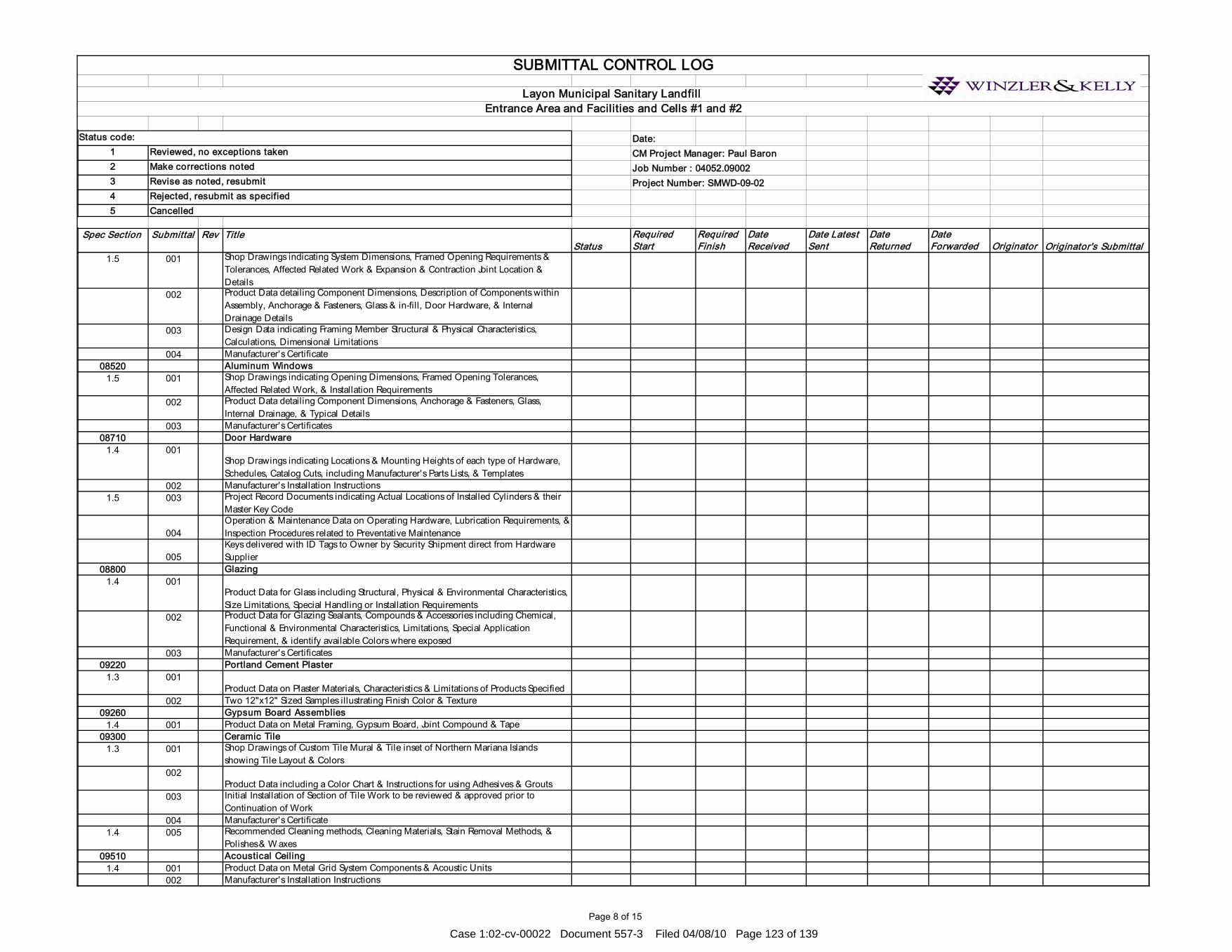
Page 8 of 15
Date:1 CM Project Manager: Paul Baron2 Job Number : 04052.090023 Project Number: SMWD-09-0245
Spec Section Submittal Rev TitleStatus
Required Start
Required Finish
Date Received
Date Latest Sent
Date Returned
Date Forwarded Originator Originator's Submittal
Rejected, resubmit as specifiedCancelled
SUBMITTAL CONTROL LOG
Layon Municipal Sanitary Landfill Entrance Area and Facilities and Cells #1 and #2
Reviewed, no exceptions takenMake corrections notedRevise as noted, resubmit
Status code:
1.5 001 Shop Drawings indicating System Dimensions, Framed Opening Requirements & Tolerances, Affected Related Work & Expansion & Contraction Joint Location & Details
002 Product Data detailing Component Dimensions, Description of Components within Assembly, Anchorage & Fasteners, Glass & in-fill, Door Hardware, & Internal Drainage Details
003 Design Data indicating Framing Member Structural & Physical Characteristics, Calculations, Dimensional Limitations
004 Manufacturer's Certificate08520 Aluminum Windows
1.5 001 Shop Drawings indicating Opening Dimensions, Framed Opening Tolerances, Affected Related Work, & Installation Requirements
002 Product Data detailing Component Dimensions, Anchorage & Fasteners, Glass, Internal Drainage, & Typical Details
003 Manufacturer's Certificates08710 Door Hardware
1.4 001Shop Drawings indicating Locations & Mounting Heights of each type of Hardware, Schedules, Catalog Cuts, including Manufacturer's Parts Lists, & Templates
002 Manufacturer's Installation Instructions1.5 003 Project Record Documents indicating Actual Locations of Installed Cylinders & their
Master Key Code
004Operation & Maintenance Data on Operating Hardware, Lubrication Requirements, & Inspection Procedures related to Preventative Maintenance
005Keys delivered with ID Tags to Owner by Security Shipment direct from Hardware Supplier
08800 Glazing1.4 001
Product Data for Glass including Structural, Physical & Environmental Characteristics, Size Limitations, Special Handling or Installation Requirements
002 Product Data for Glazing Sealants, Compounds & Accessories including Chemical, Functional & Environmental Characteristics, Limitations, Special Application Requirement, & identify available Colors where exposed
003 Manufacturer's Certificates09220 Portland Cement Plaster
1.3 001Product Data on Plaster Materials, Characteristics & Limitations of Products Specified
002 Two 12"x12" Sized Samples illustrating Finish Color & Texture09260 Gypsum Board Assemblies
1.4 001 Product Data on Metal Framing, Gypsum Board, Joint Compound & Tape09300 Ceramic Tile
1.3 001 Shop Drawings of Custom Tile Mural & Tile inset of Northern Mariana Islands showing Tile Layout & Colors
002Product Data including a Color Chart & Instructions for using Adhesives & Grouts
003 Initial Installation of Section of Tile Work to be reviewed & approved prior to Continuation of Work
004 Manufacturer's Certificate1.4 005 Recommended Cleaning methods, Cleaning Materials, Stain Removal Methods, &
Polishes & W axes09510 Acoustical Ceiling
1.4 001 Product Data on Metal Grid System Components & Acoustic Units002 Manufacturer's Installation Instructions
Case 1:02-cv-00022 Document 557-3 Filed 04/08/10 Page 123 of 139

Page 9 of 15
Date:1 CM Project Manager: Paul Baron2 Job Number : 04052.090023 Project Number: SMWD-09-0245
Spec Section Submittal Rev TitleStatus
Required Start
Required Finish
Date Received
Date Latest Sent
Date Returned
Date Forwarded Originator Originator's Submittal
Rejected, resubmit as specifiedCancelled
SUBMITTAL CONTROL LOG
Layon Municipal Sanitary Landfill Entrance Area and Facilities and Cells #1 and #2
Reviewed, no exceptions takenMake corrections notedRevise as noted, resubmit
Status code:
09650 Resilient Flooring1.3 001 Product Data describing Physical & Performance Characteristics, including Sizes,
Patterns, Colors Available, & Installation Instructions002 Manufacturer's Complete Set of Color Samples for Initial Selection
1.4 003 Maintenance Procedures, Recommended Maintenance Materials, & Suggested Schedule for Cleaning, Stripping, & Re-Waxing
09900 Paints & Coatings1.4 001 Product Data on Finishing Products
002 Special Surface Preparation Procedures, & Substrate Conditions Requiring Special Attention
003 Manufacturer's Samples of Paint Colors1.5 004 Data on Cleaning, Touch-up, & Repair of Painted & Coated Surfaces
10171 Solid Phonetic Toilet Compartments1.3 001 Shop Drawings indicating Partition Plan, Elevation Views, Dimensions, Details of
Wall, Ceiling Supports, & Door Swings002 Product Data on Panel Construction, Hardware, & Accessories003 Two 6"x6" Sized Samples illustrating Panel Finish, Color, & Sheen004 Special Procedures, Perimeter Conditions Requiring Special Attention
10440 Signs1.3 001 Shop Drawings indicating Sign Styles, Letting Font, Foreground & Background Colors,
Locations, Overall Dimensions of each sign002 Installation Template & Attachment Devices
10500 Lockers1.3 001 Shop Drawings indicating Locker Plan Layout & Numbering Plan
002 Product Data on Locker Types, Sizes & Accessories003
Two 3"x6" Sized Samples of each Color Selected, Applied to Specified Base Metal004 Installation Template & Attachment Devices
10523 Fire Extinguishers & Cabinets1.4 001 Extinguisher Operational Features, Color & Finish, & Anchorage Details
002 Special Criteria & Wall Opening Coordination Requirements1.5 003 Test, Refill or Recharge Schedules & Re-Certification Requirements
10716 Typhoon Shutters1.4 001 Shop Drawings coordinated with Window Schedule, Elevations of Shutter Units, Half-
Sized Sections, Thickness & Gages of Materials, Fastenings, Method of Anchorage, Size & Spacing of Anchors, & Location of Hardware
002 Shop Drawings of Schedule of Shutters003 Product Data for Accordion Shutters
1.8 004 Manufacturer's Operation & Maintenance Data10800 Toilet Accessories
1.3 001 Product Data on Accessories describing Size, Finish, Details of Function, Attachment Methods
002 Special Procedures, Conditions Requiring Special Attention13211
Ground Level Steel (Potable) Water, Leachate & Subdrain Storage Tanks1.3 001 Fabrication and/or Erection Drawings including Construction Details & Materials of
Construction002 Product Technical Data including Acknowledgement that Products Submitted meet
Requirements of Standards Referenced, Manufacturer's Installation Instructions, Design Data, Manufacturer's List of Five Similar Sized Reservoirs, & Cathodic Protection System Design & Details
003 Test Reports004 Operation & Maintenance Manuals
Case 1:02-cv-00022 Document 557-3 Filed 04/08/10 Page 124 of 139

Page 10 of 15
Date:1 CM Project Manager: Paul Baron2 Job Number : 04052.090023 Project Number: SMWD-09-0245
Spec Section Submittal Rev TitleStatus
Required Start
Required Finish
Date Received
Date Latest Sent
Date Returned
Date Forwarded Originator Originator's Submittal
Rejected, resubmit as specifiedCancelled
SUBMITTAL CONTROL LOG
Layon Municipal Sanitary Landfill Entrance Area and Facilities and Cells #1 and #2
Reviewed, no exceptions takenMake corrections notedRevise as noted, resubmit
Status code:
005 One 12"x12" Glass-Fused-to-Steel Reservoir Sample showing Actual Color prior to Fabrication of Reservoirs
15010 Basic Mechanical Requirements1.6 001 Shop Drawings including Floor Plans, Sectional Views, Wiring Diagrams, &
Installation Details of Equipment, & Equipment Spaces identifying & indicating Proposed Location, Layout & Arrangement of Items of Equipment, Control Panels, Accessories, & Piping Ductwork.
002 Descriptive Literature of Cataloged Products, Equipment Drawings, Diagrams, Performance & Characteristic Curves, & Catalog Cuts
003 Proof of Conformance with ANSI, ASTM, NEMA, & UL004 Certificates of Conformance or Compliance from the Manufacturer attesting that
Materials & Equipment to be furnished for this Project comply with Requirements of Specifications
15121 Piping Expansion Compensation1.3 001
Details of Flexible Pipe Connectors indicating Maximum Temperature & Pressure Rating, Face-to-Face Length, Live Length, Hose Wall Thickness, Hose Convolutions per Foot (Meter) & per Assembly, Fundamental Frequency of Assembly, Braid Structure, Total Number of Wires in Braid, & Adjustment Instructions
002 Manufacturer's Installation Instructions indicating Special Procedures & External Controls
15140 Supports & Anchors1.4 001 Manufacturer's Catalog Data detailing Load Capacity
002 Manufacturer's Installation Instructions indicating Special Procedures & Assembly of Components
003 Support & Bracing Shop Drawings including Plans, Sections, Details, Schedules & other Information necessary to describe Supports, Hangers & Seismic Bracing for all Mechanical Systems, Equipment, Piping & Ductwork (Indicate Location & Type of all Hangers, Supports, & Seismic Bracing)
004 Maintenance Data & Parts List for each Type of Support & Anchor15170 Motors
1.4 001 Wiring Diagrams with Electrical Characteristics & Connection Requirements002 Test Reports indicating Test Results verifying Nominal Efficiency & Power Factor for
Three-Phase Motors larger than 5 Horsepower003 Manufacturer's Installation Instructions indicating Setting, Mechanical Connections,
Lubrication, & Wiring Instructions15190 Mechanical Identification
1.4 001 Wording, Symbols, Letter Size, & Color Coding for Mechanical Identification002 Valve Chart & Schedule, including Valve Tag Number, Location, Function, & Valve
Manufacturer's Name & Model Number003 Manufacturer's Catalog Literature for each Product Required004 Two Samples for each Product005
Manufacturer's Installation Instructions indicating Special Procedures & Installation15245 Vibration Isolation
1.4 001Shop Drawings indicating Inertia Bases, Location of Vibration Isolators & Seismic Restraint, including Details of Suspension for Ceiling-Hung Equipment
002 Catalog Cuts of Vibration Isolators & Seismic Restraints003 Manufacturer's Installation Instructions indicating Special Procedures & Setting
Dimensions004 Seismic Certification & Analysis005 Code Requirements
Case 1:02-cv-00022 Document 557-3 Filed 04/08/10 Page 125 of 139

Page 11 of 15
Date:1 CM Project Manager: Paul Baron2 Job Number : 04052.090023 Project Number: SMWD-09-0245
Spec Section Submittal Rev TitleStatus
Required Start
Required Finish
Date Received
Date Latest Sent
Date Returned
Date Forwarded Originator Originator's Submittal
Rejected, resubmit as specifiedCancelled
SUBMITTAL CONTROL LOG
Layon Municipal Sanitary Landfill Entrance Area and Facilities and Cells #1 and #2
Reviewed, no exceptions takenMake corrections notedRevise as noted, resubmit
Status code:
15260 Piping Insulation1.4 001 Product Description, Thermal Characteristics, List of Materials & Thickness for each
Service, & Locations1.5 002 Installation Procedures
15290 Ductwork Insulation1.4 001 Product Description, Thermal Characteristics, List of Materials & Thickness for each
Service, & Locations002 Two Samples of any Representative Size illustrating each Insulation Type
1.5 003 Installation Procedures15320 Fire Pump
1.6 001 Manufacturer's Literature including General Assembly, Pump Curves showing Performance Characteristics with Pump & System, Operating Point indicated, NPSH Curve, Controls, Wiring Diagrams, & Service Connections
002 Shop Drawings indicating Layout, General Assembly, Components, Dimensions, Weights, Clearances, & Methods of Assembly
1.7 003 Results of Hydrostatic Test & Field Acceptance Tests performedManufacturer's Instructions indicating Support Details & Connection Requirements for Fire Pump System
1.8 004Project Record Documents indicating Actual Locations of Components & Accessories
005Certificates for Pump along with Summary & Results of Shop Tests performed
006 Operation Data including Manufacturer's Instructions, Start-up Data, & Troubleshooting Checklists for Pumps, Drivers, & Controllers
007 Manufacturer's Li terature detailing Cleaning Procedures, Replacement Parts Lists, & Repair Data for Pump, Driver & Controller
15410 Plumbing Piping1.4 001 Product Data on Pipe Materials, Pipe Fittings, Valves, Accessories, & Manufacturer's
Catalog Information (Indicate Valve Data & Ratings)002 Complete Installation Shop Drawings indicating all Locations & Invert Elevations of
Plumbing Piping1.5 003 Project Record Documents indicating Actual Locations of Valves
15430 Plumbing Specialties1.4 001 Product Data detailing Component Sizes, Rough-in Requirements, Service Sizes, &
Finishes002
Shop Drawings indicating Dimensions, Weights, & Placement of Openings & Holes1.5 003 Project Record Documents indicating Actual Locations of Equipment, Cleanouts,
Backflow Preventers, & Water Hammer Arrestors15440 Plumbing Fixtures
1.3 001 Catalog illustrations of Fixtures, Sizes, Rough-in Dimensions, Utility Sizes, Trim, & Finishes
1.4 002 Manufacturer's Instructions indicating Installation Methods & Procedures1.5 003
Maintenance Data including Fixture Trim Exploded View & Replacement Parts List15450 Plumbing Equipment
1.4 001Dimension Drawings of Water Heaters indicating Components, Connections to other Equipment & Piping, Electrical Characteristics, & Connection Requirements
002 Operation & Maintenance Data including Operation, Maintenance & Inspection Data, Replacement Part Numbers & Availability, & Service Depot Location & Telephone Number
15481 Compressed Air System
Case 1:02-cv-00022 Document 557-3 Filed 04/08/10 Page 126 of 139
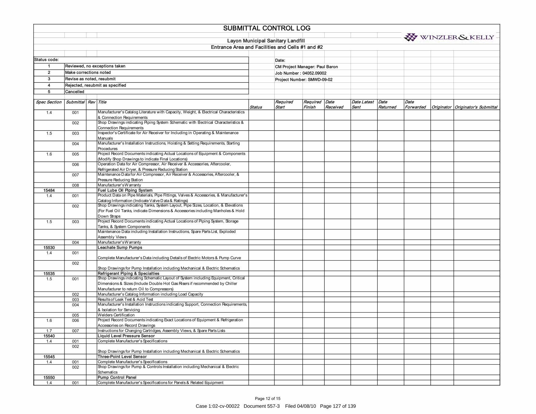
Page 12 of 15
Date:1 CM Project Manager: Paul Baron2 Job Number : 04052.090023 Project Number: SMWD-09-0245
Spec Section Submittal Rev TitleStatus
Required Start
Required Finish
Date Received
Date Latest Sent
Date Returned
Date Forwarded Originator Originator's Submittal
Rejected, resubmit as specifiedCancelled
SUBMITTAL CONTROL LOG
Layon Municipal Sanitary Landfill Entrance Area and Facilities and Cells #1 and #2
Reviewed, no exceptions takenMake corrections notedRevise as noted, resubmit
Status code:
1.4 001 Manufacturer's Catalog Literature with Capacity, Weight, & Electrical Characteristics & Connection Requirements
002 Shop Drawings indicating Piping System Schematic with Electrical Characteristics & Connection Requirements
1.5 003 Inspector's Certificate for Air Receiver for Including in Operating & Maintenance Manuals
004 Manufacturer's Installation Instructions, Hoisting & Setting Requirements, Starting Procedures
1.6 005 Project Record Documents indicating Actual Locations of Equipment & Components (Modify Shop Drawings to indicate Final Locations)
006 Operation Data for Air Compressor, Air Receiver & Accessories, Aftercooler, Refrigerated Air Dryer, & Pressure Reducing Station
007 Maintenance Data for Air Compressor, Air Receiver & Accessories, Aftercooler, & Pressure Reducing Station
008 Manufacturer's Warranty 15484 Fuel Lube Oil Piping System
1.4 001 Product Data on Pipe Materials, Pipe Fittings, Valves & Accessories, & Manufacturer's Catalog Information (Indicate Valve Data & Ratings)
002 Shop Drawings indicating Tanks, System Layout, Pipe Sizes, Location, & Elevations (For Fuel Oil Tanks, indicate Dimensions & Accessories including Manholes & Hold Down Straps
1.5 003 Project Record Documents indicating Actual Locations of Piping System, Storage Tanks, & System ComponentsMaintenance Data including Installation Instructions, Spare Parts List, Exploded Assembly Views
004 Manufacturer's Warranty 15530 Leachate Sump Pumps
1.4 001Complete Manufacturer's Data including Details of Electric Motors & Pump Curve
002Shop Drawings for Pump Installation including Mechanical & Electric Schematics
15535 Refrigerant Piping & Specialties1.5 001 Shop Drawings indicating Schematic Layout of System including Equipment, Critical
Dimensions & Sizes (Include Double Hot Gas Risers if recommended by Chiller Manufacturer to return Oil to Compressors)
002 Manufacturer's Catalog Information including Load Capacity003 Results of Leak Test & Acid Test004 Manufacturer's Installation Instructions indicating Support, Connection Requirements,
& Isolation for Servicing005 Welders Certification
1.6 006 Project Record Documents indicating Exact Locations of Equipment & Refrigeration Accessories on Record Drawings
1.7 007 Instructions for Changing Cartridges, Assembly Views, & Spare Parts Lists15540 Liquid Level Pressure Sensor
1.4 001 Complete Manufacturer's Specifications002
Shop Drawings for Pump Installation including Mechanical & Electric Schematics15545 Three-Point Level Sensor
1.4 001 Complete Manufacturer's Specifications002 Shop Drawings for Pump & Controls Installation including Mechanical & Electric
Schematics15550 Pump Control Panel
1.4 001 Complete Manufacturer's Specifications for Panels & Related Equipment
Case 1:02-cv-00022 Document 557-3 Filed 04/08/10 Page 127 of 139

Page 13 of 15
Date:1 CM Project Manager: Paul Baron2 Job Number : 04052.090023 Project Number: SMWD-09-0245
Spec Section Submittal Rev TitleStatus
Required Start
Required Finish
Date Received
Date Latest Sent
Date Returned
Date Forwarded Originator Originator's Submittal
Rejected, resubmit as specifiedCancelled
SUBMITTAL CONTROL LOG
Layon Municipal Sanitary Landfill Entrance Area and Facilities and Cells #1 and #2
Reviewed, no exceptions takenMake corrections notedRevise as noted, resubmit
Status code:
002 Narrative Description & Logic Diagram for Control System003 Electrical Schematic & Single-Line Diagram
15560 Leachate Flow Meters1.4 001
Complete Manufacturer's Specifications for Flow Meters & Related Equipment002 Shop Drawings for Installation of Sensors & Display Units003 Electrical Schematic & Single-Line Diagram 004 Operation & Maintenance Manual For Flow Meter
Section Breakout Junction Box1.4 001 Complete Manufacturer's Specifications for Breakout Junction Box
002 Shop Drawings for Installation of Pumps & Controls003 Electrical Schematic & Single-Line Diagram
15671 Air-Cooled Condensing Units1.4 001 Shop Drawings indicating Components, Assembly, Dimensions, Weights & Loadings,
Required Clearances, & Location & Size of Field Connections (Include Layouts showing Condensing Units, Cooling Coils, Refrigerant Piping, & Accessories Required for Complete System)
002Rated Capacities, Weights Specialties & Accessories, Electrical Name Plate Data, & Wiring Diagrams (Submission with Air Handling Units should refer to Section 15855)
1.5 003 Design Data indicating Pipe SizingManufacturer's Installation Instructions
1.6 004 Operation & Maintenance Data including Start-up Instructions, Maintenance Instructions, Parts Lists, Controls, & Accessories
1.9 005 Manufacturer's Warranty 15855 Air Handling Units
1.4 001 Published Literature, & Data for Filters, Fans, Sound Power Level, & Electrical Requirements
002 Shop Drawings indicating Assembly, Unit Dimensions, Weight Loading, Required Clearances, Construction Details, Field Connection Details, & Electrical Characteristics & Connection Requirements
003 Manufacturer's InstructionsMaintenance Data including Instructions for Lubrication, Filter Replacement, Motor & Drive Replacement, Spare Parts Lists, & Wiring Diagrams
15890 Ductwork Accessories1.5 001
Shop Drawings indicating Duct Fittings, Particulars such as Gages, Sizes, Welds, & Configuration prior to Start of Work (Include Duct Supports with Sway Braces)
002 Product Data for Duct Materials1.6 003
Project Record Documents indicating Actual Locations of Ducts & Duct Fittings15910 Ductwork Accessories
1.4 001 Manufacturer's Installation Instructions indicating Fire Dampers & Combination Fire & Smoke Dampers
002 Project Record Documents indicating Actual Locations of Test Holes15940 Air Outlets & Inlets
1.4 001 Product Data for Equipment required for this Project & Schedule of Outlets & Inlets showing Type, Size, Location, Application, & Noise Level
1.5 002 Project Record Documents indicating Actual Locations of Air Outlets & Inlets15990 Testing, Adjusting, & Balancing
1.3 001 Test Reports002 Name & Qualification of Adjusting & Balancing Agency
Case 1:02-cv-00022 Document 557-3 Filed 04/08/10 Page 128 of 139

Page 14 of 15
Date:1 CM Project Manager: Paul Baron2 Job Number : 04052.090023 Project Number: SMWD-09-0245
Spec Section Submittal Rev TitleStatus
Required Start
Required Finish
Date Received
Date Latest Sent
Date Returned
Date Forwarded Originator Originator's Submittal
Rejected, resubmit as specifiedCancelled
SUBMITTAL CONTROL LOG
Layon Municipal Sanitary Landfill Entrance Area and Facilities and Cells #1 and #2
Reviewed, no exceptions takenMake corrections notedRevise as noted, resubmit
Status code:
003Field Reports indicating Deficiencies in System that would prevent Proper Testing, Adjusting, & Balancing of Systems & Equipment to achieve specified Performance
004 Draft Reports indicating Adjusting, Balancing, & Equipment Data Required005 Draft Copies of Report for Review006 Draft Report Indication Adjusting, Balancing, & Equipment Data.
1.4 007 Project Record Documents indicating Actual Locations of Flow Measuring Stations Balancing Valves & Rough Setting
16050 Basic Electrical Materials & Methods1.5.1 001 Manufacturer's Catalog Data 1.5.2 002 Drawings including Wiring Diagrams & Installation Details of Equipment1.5.3 003 Manufacturer's Instructions1.5.4 004 Manufacturer's Certificates
1.5.4.1 005 Reference Standard Compliance 1.5.4.2 006 Independent Testing Organization Certificate 1.5.5 007 Operation & Maintenance Manuals
1.5.5.1 008 Operating Instructions 16302 Underground Transmission & Distribution
1.3 001 Megger Test Reports for all 600-Volt Wire & Cable Tests2.0 002 Heat Fusion Work Plan
003 Pipe Joint Test Methods, Procedures, & Apparatus004 Product Data for Piping Materials005 Product Data for Fusion Equipment006 Test Reports for Heat Fusion Daily Logs007 Test Reports for Bent Strap Testing008 Test Reports for Ultrasonic Testing009 Certificate for Fusion Equipment Experience Requirements010 Certificate for Experience Requirements011 Certification for NDE Technician012 Pipe Manufacturer Material Certificate013 Mechanical Coupling Manufacturer Certificate014 Certification for Heat Fusion Technician
2.4 015 Primary/Secondary and Communication Handhole Hardwares16402 Interior Distribution System1.3.1 001 Shop Drawings of Panel Boards & Wireways
1.3.2002 Product Data for Receptacles, Circuit Breakers, Switches, Enclosed Circuit Breakers,
Manual Motor Starters, CATV Outlets, Grounding Block
1.3.3003 Test Reports for 600-Volt Wiring Test, Grounding System Test, Ground-Fault
Receptacle Test1.5.1 004 Operation & Maintenance Manuals for Electrical Systems including Single-Line
Diagram of the "As-Built" Building Electrical System, & Schematic Diagram of Electrical Control System
16510 Interior Lighting1.4.1 001
Product Data for Fluorescent Lighting Fixtures, Electronic Ballasts & Lamps, Incandescent Lighting Fixtures & Lamps, Dimmer Switch, Lighting Contactor, Time Switch, Photocell Switch, Exit Signs, Emergency Lighting Equipment, Occupancy Sensors, Electronic Dimming Ballast, & Dimming Ballast Controls
1.4.2 002 Samples of Lighting Fixtures, complete with Lamps & Ballasts1.4.3 003 Operating Test Reports1.4.4 004 Operation & Maintenance Data showing all Control Modules, Control Zones,
Occupancy Sensors, Light Fixtures, & all Interconnecting Control Wire, Conduit, & Associated Hardware
Case 1:02-cv-00022 Document 557-3 Filed 04/08/10 Page 129 of 139

Page 15 of 15
Date:1 CM Project Manager: Paul Baron2 Job Number : 04052.090023 Project Number: SMWD-09-0245
Spec Section Submittal Rev TitleStatus
Required Start
Required Finish
Date Received
Date Latest Sent
Date Returned
Date Forwarded Originator Originator's Submittal
Rejected, resubmit as specifiedCancelled
SUBMITTAL CONTROL LOG
Layon Municipal Sanitary Landfill Entrance Area and Facilities and Cells #1 and #2
Reviewed, no exceptions takenMake corrections notedRevise as noted, resubmit
Status code:
1.4.5 005 Information Card16520 Exterior Lighting
1.4 001 Luminaire Drawings including Poles002 Product Data on Luminaires, Lamps, Ballasts, Lighting Contactor, Time Switch,
Photocell Switch, Concrete Poles, & Brackets003 Operating Test Reports for Luminaires
16612 Emergency Power System1.0 001 Manufacturer's Brochures describing Equipment Ratings, Performances, Specification
& Construction002 Shop Drawings of Layout to Scale giving Dimensions, Schematic & Wiring Diagrams,
& Interconnection Diagrams003 Manufacturer's Warranty
16721 Fire Alarm System001 Technical Data, Wiring Diagrams, & Installation & Maintenance Instructions
Case 1:02-cv-00022 Document 557-3 Filed 04/08/10 Page 130 of 139
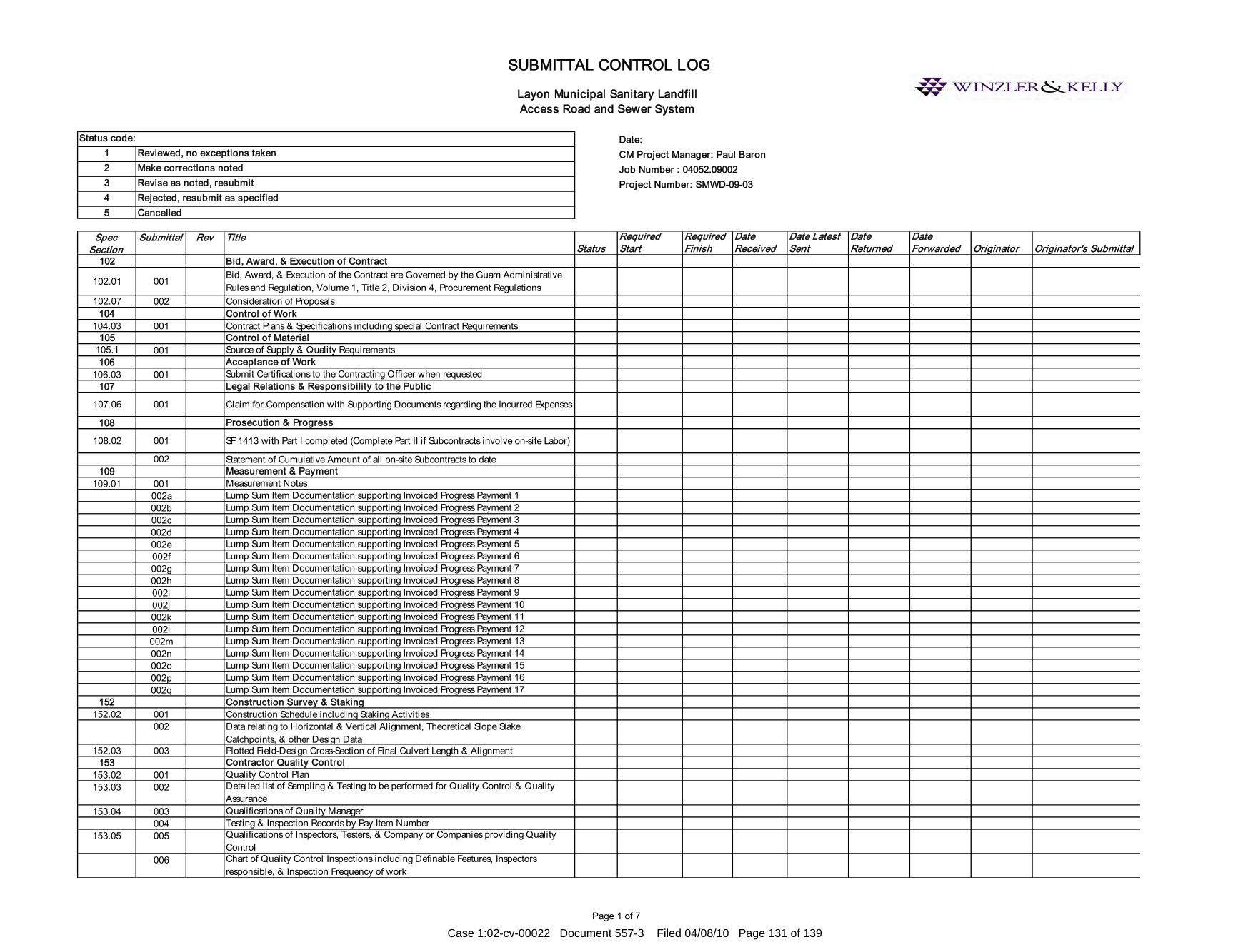
Page 1 of 7
Date:1 CM Project Manager: Paul Baron2 Job Number : 04052.090023 Project Number: SMWD-09-0345
Spec Section
Submittal Rev TitleStatus
Required Start
Required Finish
Date Received
Date Latest Sent
Date Returned
Date Forwarded Originator Originator's Submittal
102 Bid, Award, & Execution of Contract
102.01 001Bid, Award, & Execution of the Contract are Governed by the Guam Administrative Rules and Regulation, Volume 1, Title 2, Division 4, Procurement Regulations
102.07 002 Consideration of Proposals104 Control of Work
104.03 001 Contract Plans & Specifications including special Contract Requirements105 Control of Material
105.1 001 Source of Supply & Quality Requirements106 Acceptance of Work
106.03 001 Submit Certifications to the Contracting Officer when requested107 Legal Relations & Responsibility to the Public
107.06 001 Claim for Compensation with Supporting Documents regarding the Incurred Expenses
108 Prosecution & Progress
108.02 001 SF 1413 with Part I completed (Complete Part II if Subcontracts involve on-site Labor)
002 Statement of Cumulative Amount of all on-site Subcontracts to date109 Measurement & Payment
109.01 001 Measurement Notes002a Lump Sum Item Documentation supporting Invoiced Progress Payment 1002b Lump Sum Item Documentation supporting Invoiced Progress Payment 2002c Lump Sum Item Documentation supporting Invoiced Progress Payment 3002d Lump Sum Item Documentation supporting Invoiced Progress Payment 4002e Lump Sum Item Documentation supporting Invoiced Progress Payment 5002f Lump Sum Item Documentation supporting Invoiced Progress Payment 6002g Lump Sum Item Documentation supporting Invoiced Progress Payment 7002h Lump Sum Item Documentation supporting Invoiced Progress Payment 8002i Lump Sum Item Documentation supporting Invoiced Progress Payment 9002j Lump Sum Item Documentation supporting Invoiced Progress Payment 10002k Lump Sum Item Documentation supporting Invoiced Progress Payment 11002l Lump Sum Item Documentation supporting Invoiced Progress Payment 12002m Lump Sum Item Documentation supporting Invoiced Progress Payment 13002n Lump Sum Item Documentation supporting Invoiced Progress Payment 14002o Lump Sum Item Documentation supporting Invoiced Progress Payment 15002p Lump Sum Item Documentation supporting Invoiced Progress Payment 16002q Lump Sum Item Documentation supporting Invoiced Progress Payment 17
152 Construction Survey & Staking 152.02 001 Construction Schedule including Staking Activities
002 Data relating to Horizontal & Vertical Alignment, Theoretical Slope Stake Catchpoints, & other Design Data
152.03 003 Plotted Field-Design Cross-Section of Final Culvert Length & Alignment153 Contractor Quality Control
153.02 001 Quality Control Plan153.03 002 Detailed list of Sampling & Testing to be performed for Quality Control & Quality
Assurance153.04 003 Qualifications of Quality Manager
004 Testing & Inspection Records by Pay Item Number153.05 005 Qualifications of Inspectors, Testers, & Company or Companies providing Quality
Control006 Chart of Quality Control Inspections including Definable Features, Inspectors
responsible, & Inspection Frequency of work
Cancelled
Layon Municipal Sanitary Landfill Access Road and Sewer System
SUBMITTAL CONTROL LOG
Status code:Reviewed, no exceptions takenMake corrections notedRevise as noted, resubmitRejected, resubmit as specified
Case 1:02-cv-00022 Document 557-3 Filed 04/08/10 Page 131 of 139
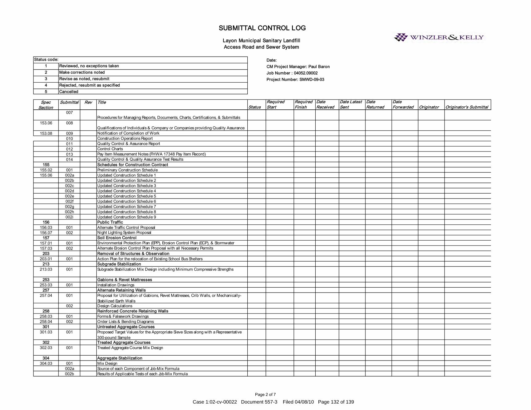
Page 2 of 7
Date:1 CM Project Manager: Paul Baron2 Job Number : 04052.090023 Project Number: SMWD-09-0345
Spec Section
Submittal Rev TitleStatus
Required Start
Required Finish
Date Received
Date Latest Sent
Date Returned
Date Forwarded Originator Originator's Submittal
Cancelled
Layon Municipal Sanitary Landfill Access Road and Sewer System
SUBMITTAL CONTROL LOG
Status code:Reviewed, no exceptions takenMake corrections notedRevise as noted, resubmitRejected, resubmit as specified
007Procedures for Managing Reports, Documents, Charts, Certifications, & Submittals
153.06 008Qualifications of Individuals & Company or Companies providing Quality Assurance
153.08 009 Notification of Completion of Work010 Construction Operations Report011 Quality Control & Assurance Report012 Control Charts013 Pay Item Measurement Notes (FHWA 17348 Pay Item Record)014 Quality Control & Quality Assurance Test Results
155 Schedules for Construction Contract 155.02 001 Preliminary Construction Schedule155.06 002a Updated Construction Schedule 1
002b Updated Construction Schedule 2002c Updated Construction Schedule 3002d Updated Construction Schedule 4002e Updated Construction Schedule 5002f Updated Construction Schedule 6002g Updated Construction Schedule 7002h Updated Construction Schedule 8002i Updated Construction Schedule 9
156 Public Traffic 156.03 001 Alternate Traffic Control Proposal156.07 002 Night Lighting System Proposal
157 Soil Erosion Control 157.01 001 Environmental Protection Plan (EPP), Erosion Control Plan (ECP), & Stormwater 157.03 002 Alternate Erosion Control Plan Proposal with all Necessary Permits
203 Removal of Structures & Observation 203.01 001 Action Plan for the relocation of Existing School Bus Shelters
213 Subgrade Stabilization213.03 001 Subgrade Stabilization Mix Design including Minimum Compressive Strengths
253 Gabions & Revet Mattresses253.03 001 Installation Drawings
257 Alternate Retaining Walls257.04 001 Proposal for Utilization of Gabions, Revet Mattresses, Crib Walls, or Mechanically-
Stabilized Earth Walls002 Design Calculations
258 Reinforced Concrete Retaining Walls258.03 001 Forms & Falsework Drawings 258.04 002 Order Lists & Bending Diagrams
301 Untreated Aggregate Courses301.03 001 Proposed Target Values for the Appropriate Sieve Sizes along with a Representative
300-pound Sample302 Treated Aggregate Courses
302.03 001 Treated Aggregate Course Mix Design
304 Aggregate Stabilization304.03 001 Mix Design
002a Source of each Component of Job-Mix Formula002b Results of Applicable Tests of each Job-Mix Formula
Case 1:02-cv-00022 Document 557-3 Filed 04/08/10 Page 132 of 139

Page 3 of 7
Date:1 CM Project Manager: Paul Baron2 Job Number : 04052.090023 Project Number: SMWD-09-0345
Spec Section
Submittal Rev TitleStatus
Required Start
Required Finish
Date Received
Date Latest Sent
Date Returned
Date Forwarded Originator Originator's Submittal
Cancelled
Layon Municipal Sanitary Landfill Access Road and Sewer System
SUBMITTAL CONTROL LOG
Status code:Reviewed, no exceptions takenMake corrections notedRevise as noted, resubmitRejected, resubmit as specified
002c Target Values for Each Aggregate Sieve Size Specified & Stabilizing Agent for each Job-Mix Formula
003a 200-Pound Sample of Aggregate003b 50-Pound Sample of Fly Ash003c 25-Pound Sample of Lime003d 25-Pound Sample of Portland & Cement
003e 5-Pound Sample of Retarder or Other Admixtures309 Emulsified Asphalt-Treated Base Course
309.03 001 Proposed Target Values for the Appropriate Sieve Sizes Along with a Representative 300-Pound Sample
402 Hot Asphalt Concrete Pavement by HVEEM or Marshall Mix Design Method
402.03 001 Written Job-Mix Formulas with Form FHWA 1607 (HVEEM) or Form FHWA 1608 (Marshall)
002 Laboratory Certification for Proposed Job-Mix Formula including Acceptance & Payment for each Job Mix
403 Hot Asphalt Concrete Pavement 403.03 001 Aggregate Quality, Gradation Requirements, & Mixture Criteria for the Asphalt
Concrete Mix002 Written Job-Mix Formulas including the Location of all Commercial Mixing Plants to
be used & a Separate Job-Mix Formula for each Plant003 Target Values for Percent Passing Each Sieve Size for the Aggregate Blend & each
Stockpile, Stockpile Blend Ratios, Target Asphalt Binder Content, & Maximum Density Value
004 Aggregate Sources005 Stockpile Gradations006 Representative Samples007 Results of Aggregate Quality Tests for Contractor Selected Sources008 Asphalt Binder Information009 Antistrip Additives information010 Recycled Asphalt Pavement Material information
403.12 011 Proposed Schedule of Paving Operations012 List of All Equipment & Personnel used in the Production & Construction of the Work 013 Proposed Traffic Control Plan for Paving Operations including Provisions for
Pavement Drop-offs & Moving Operations014 Contractor Quality Control Plan for Paving & Sampling & Testing015
Compacting, & Smoothness Procedures
016 Acceptance Procedures404 Minor Hot Asphalt Concrete
404.02 001 Strength, Quality, & Gradation Specifications for Asphalt Concrete Mix including Copies of Laboratory Test Reports
002 Results of AASHTO T 209 for Maximum Specific Gravity of the Mix405 Open-Graded Asphalt Friction Course
001 Written Job-Mix Formula002a Target Values for Percent Passing each Sieve Size for the Aggregate Blend &
Designate Target Values within the Gradation B & Specified for the Nominal Maximum Size Aggregate Grading
002b Source & Percentage of each Aggregate Stockpile to be used002c Average Gradation of each Aggregate Stockpile
Case 1:02-cv-00022 Document 557-3 Filed 04/08/10 Page 133 of 139

Page 4 of 7
Date:1 CM Project Manager: Paul Baron2 Job Number : 04052.090023 Project Number: SMWD-09-0345
Spec Section
Submittal Rev TitleStatus
Required Start
Required Finish
Date Received
Date Latest Sent
Date Returned
Date Forwarded Originator Originator's Submittal
Cancelled
Layon Municipal Sanitary Landfill Access Road and Sewer System
SUBMITTAL CONTROL LOG
Status code:Reviewed, no exceptions takenMake corrections notedRevise as noted, resubmitRejected, resubmit as specified
002d Representative Samples from each Aggregate Stockpile (800-Pounds of Aggregates Proportioned by Stockpile, 20-Pounds of Bag House Fines if Proposed in the Mix, & 20-Pounds of Mineral Filler if Proposed in the Mix)
002e Results of Aggregate Quality Tests003a Target Asphalt Binder Content003b Five 1-Gallon Samples of the Asphalt Binder to be used in the Mix003c Recent Test Results from the Manufacturer for the Asphalt Binder including a
Temperature-Viscosity Curve003d Material Safety Data Sheets003e Mixing Temperature Range & Minimum Compaction Temperature for the
Performance Grade Asphalt to be used in the Mix004a 1-Pint of Liquid Antistrip Additive or 10-Pounds of Cement, Fly Ash, or Lime Antistrip
Additive004b Name of the Product004c Manufacturer's Data Sheets & Placement Procedures004d Material Safety Data Sheet004e Dosage Rate005a Source & Percentage of Recycled Asphalt Pavement Material005b Average Gradation of the Recycled Asphalt Pavement Material005c Percent Asphalt Binder in the Recycled Asphalt Pavement005d Target Value for the Asphalt Binder Content & the Percent New Asphalt Binder005e 200-Pounds Representative Sample of Recycled Asphalt Pavement Material005f One-Gallon of Recycling Agent
563 Painting563.03 001a
Environment, Public, Adjacent Property, & Workers
001b Manufacturer's Material Safety Data Sheets & Product Data Sheets001c
Detailed Containment Plan for Removed Material, Cleaning Products, & Paint Debris001d
Detailed Disposal Plan for Removed Material, Cleaning Products, & Paint Debris001e Specific Safety Measures to protect Workers from Site Hazards001f Emergency Spill Procedures001g Qualifications of Quality Control Personnel
601 Minor Concrete Structures 601.02 001 Concrete Test Results601.02 002 Certified Mix Design Test Reports for Admixtures (If any)601.03 003 Test Results of 7-Day & 28-Day Compressive Strength of Concrete Samples
611 Water Systems611.03 001 Certified Cost Breakdown of the Individual Items involved in the Lump Sum Item for
use in making Progress Payments & Price Adjustments612 Sanitary Sewer System
612.03 001 Certified Cost Breakdown of the Individual Items involved in the Lump Sum Item for use in making Progress Payments & Price Adjustments
002 Product Data indicating Pipe Material used & Pipe Accessories003 Sewer Manhole Shop Drawing
612A Wastewater Pumping Stations (Pump #3,#4)1.7 001a Guide Rail System
001b Miscellaneous Metal Fabrications001c Pump Performance Curves001d Wiring Diagram001e Pump Outline Drawing
Case 1:02-cv-00022 Document 557-3 Filed 04/08/10 Page 134 of 139
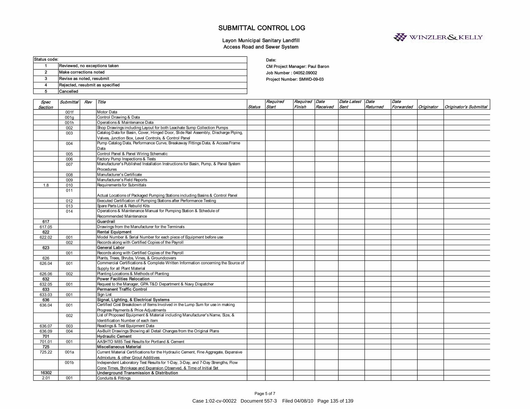
Page 5 of 7
Date:1 CM Project Manager: Paul Baron2 Job Number : 04052.090023 Project Number: SMWD-09-0345
Spec Section
Submittal Rev TitleStatus
Required Start
Required Finish
Date Received
Date Latest Sent
Date Returned
Date Forwarded Originator Originator's Submittal
Cancelled
Layon Municipal Sanitary Landfill Access Road and Sewer System
SUBMITTAL CONTROL LOG
Status code:Reviewed, no exceptions takenMake corrections notedRevise as noted, resubmitRejected, resubmit as specified
001f Motor Data 001g Control Drawing & Data001h Operations & Maintenance Data002 Shop Drawings including Layout for both Leachate Sump Collection Pumps003 Catalog Data for Basin, Cover, Hinged Door, Slide Rail Assembly, Discharge Piping,
Valves, Junction Box, Level Controls, & Control Panel004 Pump Catalog Data, Performance Curve, Breakaway Fittings Data, & Access Frame
Data005 Control Panel & Panel Wiring Schematic006 Factory Pump Inspections & Tests007 Manufacturer's Published Installation Instructions for Basin, Pump, & Panel System
Procedures008 Manufacturer's Certificate009 Manufacturer's Field Reports
1.8 010 Requirements for Submittals011
Actual Locations of Packaged Pumping Stations including Basins & Control Panel012 Executed Certification of Pumping Stations after Performance Testing013 Spare Parts List & Rebuild Kits014 Operations & Maintenance Manual for Pumping Station & Schedule of
Recommended Maintenance617 Guardrail
617.05 Drawings from the Manufacturer for the Terminals622 Rental Equipment
622.02 001 Model Number & Serial Number for each piece of Equipment before use002 Records along with Certified Copies of the Payroll
623 General Labor001 Records along with Certified Copies of the Payroll
626 Plants, Trees, Shrubs, Vines, & Groundcovers626.04 001 Commercial Certifications & Complete Written Information concerning the Source of
Supply for all Plant Material626.06 002 Planting Locations & Methods of Planting
632 Power Facilities Relocation 632.05 001 Request to the Manager, GPA T&D Department & Navy Dispatcher
633 Permanent Traffic Control633.03 001 Sign List
636 Signal, Lighting, & Electrical Systems636.04 001 Certified Cost Breakdown of Items Involved in the Lump Sum for use in making
Progress Payments & Price Adjustments002 List of Proposed Equipment & Material including Manufacturer's Name, Size, &
Identification Number of each item636.07 003 Readings & Test Equipment Data636.09 004 As-Built Drawings Showing all Detail Changes from the Original Plans
701 Hydraulic Cement 701.01 001 AASHTO M85 Test Results for Portland & Cement
725 Miscellaneous Material725.22 001a Current Material Certifications for the Hydraulic Cement, Fine Aggregate, Expansive
Admixture, & other Grout Additives001b Independent Laboratory Test Results for 1-Day, 3-Day, and 7-Day Strengths, Flow
Cone Times, Shrinkage and Expansion Observed, & Time of Initial Set16302 Underground Transmission & Distribution2.01 001 Conduits & Fittings
Case 1:02-cv-00022 Document 557-3 Filed 04/08/10 Page 135 of 139
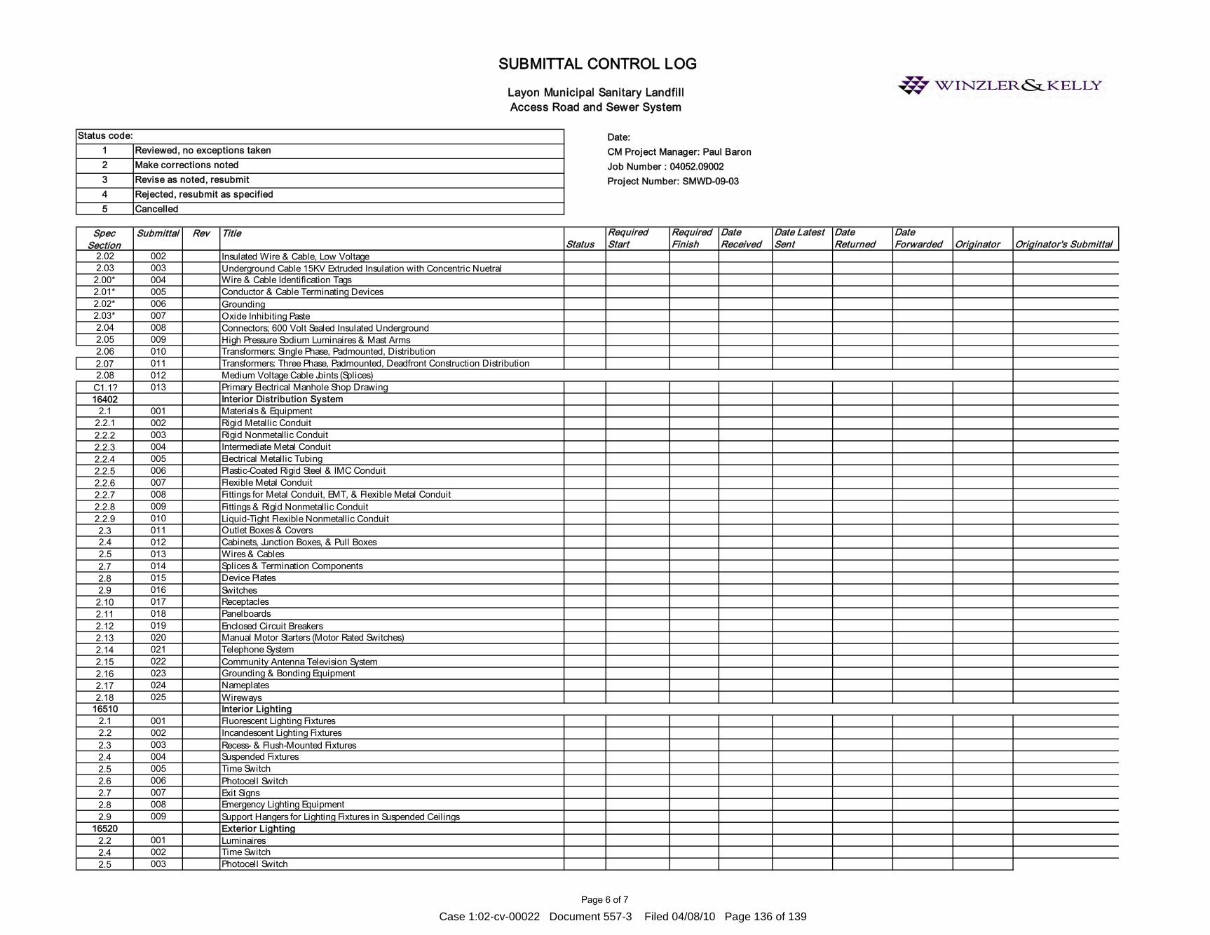
Page 6 of 7
Date:1 CM Project Manager: Paul Baron2 Job Number : 04052.090023 Project Number: SMWD-09-0345
Spec Section
Submittal Rev TitleStatus
Required Start
Required Finish
Date Received
Date Latest Sent
Date Returned
Date Forwarded Originator Originator's Submittal
Cancelled
Layon Municipal Sanitary Landfill Access Road and Sewer System
SUBMITTAL CONTROL LOG
Status code:Reviewed, no exceptions takenMake corrections notedRevise as noted, resubmitRejected, resubmit as specified
2.02 002 Insulated Wire & Cable, Low Voltage2.03 003 Underground Cable 15KV Extruded Insulation with Concentric Nuetral2.00* 004 Wire & Cable Identification Tags2.01* 005 Conductor & Cable Terminating Devices2.02* 006 Grounding2.03* 007 Oxide Inhibiting Paste2.04 008 Connectors; 600 Volt Sealed Insulated Underground2.05 009 High Pressure Sodium Luminaires & Mast Arms2.06 010 Transformers: Single Phase, Padmounted, Distribution2.07 011 Transformers: Three Phase, Padmounted, Deadfront Construction Distribution2.08 012 Medium Voltage Cable Joints (Splices)
C1.1? 013 Primary Electrical Manhole Shop Drawing16402 Interior Distribution System
2.1 001 Materials & Equipment2.2.1 002 Rigid Metallic Conduit2.2.2 003 Rigid Nonmetallic Conduit2.2.3 004 Intermediate Metal Conduit2.2.4 005 Electrical Metallic Tubing2.2.5 006 Plastic-Coated Rigid Steel & IMC Conduit2.2.6 007 Flexible Metal Conduit2.2.7 008 Fittings for Metal Conduit, EMT, & Flexible Metal Conduit2.2.8 009 Fittings & Rigid Nonmetallic Conduit2.2.9 010 Liquid-Tight Flexible Nonmetallic Conduit2.3 011 Outlet Boxes & Covers2.4 012 Cabinets, Junction Boxes, & Pull Boxes2.5 013 Wires & Cables2.7 014 Splices & Termination Components2.8 015 Device Plates2.9 016 Switches2.10 017 Receptacles2.11 018 Panelboards2.12 019 Enclosed Circuit Breakers2.13 020 Manual Motor Starters (Motor Rated Switches)2.14 021 Telephone System2.15 022 Community Antenna Television System2.16 023 Grounding & Bonding Equipment2.17 024 Nameplates2.18 025 Wireways
16510 Interior Lighting2.1 001 Fluorescent Lighting Fixtures2.2 002 Incandescent Lighting Fixtures2.3 003 Recess- & Flush-Mounted Fixtures2.4 004 Suspended Fixtures2.5 005 Time Switch2.6 006 Photocell Switch2.7 007 Exit Signs2.8 008 Emergency Lighting Equipment2.9 009 Support Hangers for Lighting Fixtures in Suspended Ceilings
16520 Exterior Lighting2.2 001 Luminaires2.4 002 Time Switch2.5 003 Photocell Switch
Case 1:02-cv-00022 Document 557-3 Filed 04/08/10 Page 136 of 139

Page 7 of 7
Date:1 CM Project Manager: Paul Baron2 Job Number : 04052.090023 Project Number: SMWD-09-0345
Spec Section
Submittal Rev TitleStatus
Required Start
Required Finish
Date Received
Date Latest Sent
Date Returned
Date Forwarded Originator Originator's Submittal
Cancelled
Layon Municipal Sanitary Landfill Access Road and Sewer System
SUBMITTAL CONTROL LOG
Status code:Reviewed, no exceptions takenMake corrections notedRevise as noted, resubmitRejected, resubmit as specified
2.6 004 Poles2.7 005 Brackets & Supports2.8 006 Pole Foundations
Case 1:02-cv-00022 Document 557-3 Filed 04/08/10 Page 137 of 139
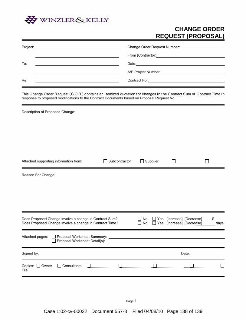
Page 1
CHANGE ORDER REQUEST (PROPOSAL)
Project:
To:
Re:
Change Order Request Number: From (Contractor): Date: A/E Project Number: Contract For:
This Change Order Request (C.O.R.) contains an i temized quotation for changes in the Contract Sum or Contract T ime in response to proposed modifications to the Contract Documents based on Proposal Request No. . Description of Proposed Change:
Attached supporting information from: Subcontractor Supplier Reason For Change:
Does Proposed Change involve a change in Contract Sum? No Yes [Increase] [Decrease] $ Does Proposed Change involve a change in Contract Time? No Yes [Increase] [Decrease] days. Attached pages: Proposal Worksheet Summary:
Proposal Worksheet Detail(s): Signed by: Date: Copies: Owner Consultants File
Case 1:02-cv-00022 Document 557-3 Filed 04/08/10 Page 138 of 139

Page 1
NONCONFORMING WORK NOTICE
Project:
To:
Re:
Report Number: From: Date Observed: Date Reported: A/E Project Number: Contract For:
Specification Section: Paragraph: Drawing Reference: Detail: Nature of Nonconformance:
Signed by: Date: Date Response Needed: Proposed Correction (Response):
Amount of Time for Correction:
Attachments Response From: To: Date Rec’d: Date Ret’d: Signed by: Date: Copies: Owner A/E Consultants File
Case 1:02-cv-00022 Document 557-3 Filed 04/08/10 Page 139 of 139

CONSTRUCTION QUALITY ASSURANCE IMPLEMENTATION PLAN
for the CELLS 1 AND 2 LINER SYSTEM
at the LAYON LANDFILL
Prepared for: Winzler & Kelly
194 Hernan Cortez Ave., Ste. 213 Hagatna, GU 96910
(671)472-6792
Prepared by:
143E Spring Hill Drive
Grass Valley, California 95945 (530) 272-2448
Project No. 101601.00 March 2010
Case 1:02-cv-00022 Document 557-4 Filed 04/08/10 Page 1 of 41

CQA Implementation Plan March 2010 Layon Landfill Project No 101601.00
Vector Engineering, Inc. • 143E Spring Hill Drive • Grass Valley, CA 95945 • (530) 272-2448 -i-
TABLE OF CONTENTS
1.0 CONSTRUCTION QUALITY ASSURANCE ............................................... 1
1.1 Introduction and Scope ............................................................................. 1 1.2 Duties of CQA Personnel .......................................................................... 1
1.2.1 Soil Quality Assurance Consultant.............................................. 2 1.2.2 Soil Quality Assurance Engineer (QAE) .................................... 3 1.2.3 The Soil CQA Monitor: .................................................................. 4 1.2.4 Geosynthetic Quality Assurance Consultant .............................. 5 1.2.5 The Geosynthetic QAE .................................................................. 5 1.2.6 Geosynthetic Construction Quality Assurance Monitor ............ 7 1.2.7 Soil Quality Assurance Laboratory .............................................. 8 1.2.8 Geosynthetic Quality Assurance Laboratory .............................. 8
2.0 EARTHWORK ................................................................................................... 9 2.1 General ....................................................................................................... 9 2.2 Soil over Subdrain Geocomposite ............................................................ 9 2.3 Low Permeability Soil ............................................................................. 10
2.3.1 General ......................................................................................... 10 2.3.2 Preconstruction ............................................................................ 10 2.3.3 Construction ................................................................................. 11 2.3.4 Post-Construction ........................................................................ 13
2.4 Anchor Trench Excavation and Backfilling .......................................... 14 2.5 Subdrain and Leachate Collection and Removal System (LCRS) ...... 15
2.5.1 General ......................................................................................... 15 2.5.2 Granular Drainage Material ...................................................... 15 2.5.3 Subdrain and Leachate Collection Piping ................................. 15
2.6 Protective Soils (Operations) Layer ...................................................... 17 2.7 Surface Water Drainage Structures ...................................................... 18 2.8 Landfill Gas Collection System ............................................................. 19
3.0 GEOMEMBRANE QUALITY ASSURANCE ............................................. 20 3.1 General ..................................................................................................... 20 3.2 Shipping and Handling .......................................................................... 20 3.3 Geomembrane Conformance Testing .................................................... 21 3.4 HDPE Geomembrane Placement .......................................................... 21 3.5 HDPE Geomembrane Test Welds ......................................................... 22 3.6 Seaming of the HDPE Geomembrane ................................................... 23
Case 1:02-cv-00022 Document 557-4 Filed 04/08/10 Page 2 of 41

CQA Implementation Plan March 2010 Layon Landfill Project No 101601.00
Vector Engineering, Inc. • 143E Spring Hill Drive • Grass Valley, CA 95945 • (530) 272-2448 -ii-
3.7 Extrusion Welding .................................................................................. 24 3.8 Hot Wedge (Fusion) Welding ................................................................. 25 3.9 Nondestructive Testing of Geomembrane Seams ................................ 25
3.9.1 General ......................................................................................... 25 3.9.2 Vacuum Box Testing ................................................................... 25 3.9.3 Air Pressure Testing ................................................................... 26
3.10 Destructive Testing of Geomembrane Seams ...................................... 27 3.11 Repairs to the Geomembrane ................................................................ 28 3.12 Geomembrane Final Walk-through ...................................................... 28
4.0 GEOCOMPOSITE quality assurance ........................................................ 30 4.1 General ..................................................................................................... 30 4.2 Shipping and Handling .......................................................................... 30 4.3 Geocomposite Conformance Testing ..................................................... 31 4.4 Geocomposite Installation ...................................................................... 31
5.0 Geotextile quality assurance ....................................................................... 32 5. 1 Geotextile Quality Control, Shipping, and Handling .......................... 32 5.2 Geotextile Conformance Testing ........................................................... 33 5.3 Geotextile Installation ............................................................................ 33
6.0 WORK DEFICIENCIES ................................................................................ 35 7.0 DOCUMENTATION ...................................................................................... 36
7.1 Daily Records ........................................................................................... 36 7.2 Observation and Test Data Sheets ........................................................ 36 7.3 Certification/CQA Final Documentation Report .................................. 37
Case 1:02-cv-00022 Document 557-4 Filed 04/08/10 Page 3 of 41

CQA Implementation Plan March 2010 Layon Landfill Project No 101601.00
Vector Engineering, Inc. • 143E Spring Hill Drive • Grass Valley, CA 95945 • (530) 272-2448 -1-
1.0 CONSTRUCTION QUALITY ASSURANCE
1.1 Introduction and Scope
This CQA Implementation Plan (Plan) describes the tasks involved with the construction quality assurance (CQA) for the Layon Landfill. CQA refers to the duties of a third party CQA Consultant to monitor, observe, and evaluate materials and workmanship during construction. The CQA activities document the compliance of the Contractor with the Drawings and Specifications for the construction. For the purposes of this Plan, the term Contractor refers to the company or individual that is responsible for performing the specific work item being examined to complete the excavation and liner construction at the site. This includes but is not limited to the earthwork contractor(s), geosynthetic installer(s), or their subcontractor(s). The overall goal of this Plan is to assure that proper construction techniques and procedures are used and that the project is built in accordance with the project Construction Drawings and Specifications. The intent is to identify and define problems that may occur during construction and to observe that these problems are corrected before construction is complete. A written final report prepared by the CQA Consultant will be prepared summarizing the construction activities and observing that the installation was performed in general accordance with the Project Construction Drawings and Specifications. Where discrepancies between this document and the Specifications exist, the Specifications shall govern the Contractor. 1.2 Duties of CQA Personnel
It is the duty and responsibility of the CQA Consultant to implement the elements of this Plan in order to ensure that the construction and installation of the composite liner system at the Project Site is performed in accordance with the Construction Drawings and Specifications and the appropriate Regulations specified to govern this work. CQA duties for this project will be in accordance with Title 27 of the California Code of
Case 1:02-cv-00022 Document 557-4 Filed 04/08/10 Page 4 of 41

CQA Implementation Plan March 2010 Layon Landfill Project No 101601.00
Vector Engineering, Inc. • 143E Spring Hill Drive • Grass Valley, CA 95945 • (530) 272-2448 -2-
Regulations. The CQA personnel shall make every effort to communicate in an efficient and effective manner to the Contractor's representatives on issues concerning testing and observation procedures and results of materials or in situ tests performed. The CQA personnel shall attend all preconstruction meetings fo the work covered by this plan. The CQA Consultant is not in a position to direct construction activities, but is encouraged to give advice to the Contractor, Winzler & Kelly (Project CM), or Gershman, Brickner & Bratton, Inc. (GBB), (Reciever) on items which may improve the quality or speed progress of the construction. The CQA Consultant and its representatives shall make every effort to furnish test results to the Contractor in a prompt manner. The representatives of the CQA Consultant shall report to the Project CM and Owner any nonconformance items, which cannot be resolved promptly. The specific definition and duties of the organizations and personnel associated with the CQA activities are described in the following sections. 1.2.1 Soil Quality Assurance Consultant
The Soil Quality Assurance Consultant (Soil QAC) is the firm which observes and documents activities related to the quality assurance of the installation of the soil components of the lining system on behalf of the Owner. The Soil QAC and Geosynthetic QAC may be the same party. The Soil QAC is responsible for observing and documenting activities related to the quality assurance of the construction of the soil components of the lining systems. The Soil QAC is responsible for the implementation of the project QAP prepared by the Project Manager. The Soil QAC is also responsible for issuing a final Quality Assurance Report, sealed by a qualified Professional Engineer. Other duties of the Soil QAC shall include overseeing the soil laboratory testing.
Case 1:02-cv-00022 Document 557-4 Filed 04/08/10 Page 5 of 41

CQA Implementation Plan March 2010 Layon Landfill Project No 101601.00
Vector Engineering, Inc. • 143E Spring Hill Drive • Grass Valley, CA 95945 • (530) 272-2448 -3-
1.2.2 Soil Quality Assurance Engineer (QAE) The term Soil Quality Assurance Engineer (Soil QAE) refers to the engineer employed by the QAC who is personally in charge of the quality assurance work. Duties of the Soil QAE included the following.
1. Reviews all project plans and specifications.
2. Reviews other site-specific documentation.
3. Develops site-specific addenda for quality assurance of soil components with the assistance of the Project Manager as necessary.
4. Administers the soil portions of the QAP, including assigning and managing all soil quality assurance personnel, reviews all field reports, and provides engineering review of all quality assurance related issues.
5. Familiarizes himself with all applicable changes to project plans and specifications as issued by the Designer.
6. Acts as on-site (resident) representative of the Soil QAC.
7. Familiarizes all Soil QA Monitors with the site and the project QAP.
8. Assigns Soil QA Monitors to observe and document all activities requiring monitoring.
9. Attends all quality assurance related meetings, including resolution, pre-construction, daily, weekly meetings.
10. Reviews the calibration certification of the on-site soil testing equipment.
11. Manages the preparation of the record drawings.
12. Reviews the Soil QA Monitors’ daily reports, logs, and photographs.
13. Notes any on-site activities that could result in damage to the installed soil components.
14. Reports to the Project Manager, and logs in the daily report, any relevant observations reported by the Soil QA Monitors.
15. Prepares his own daily report.
16. Prepares a daily summary of the soil component quantities estimates installed each day of construction activity.
Case 1:02-cv-00022 Document 557-4 Filed 04/08/10 Page 6 of 41
CQA Implementation Plan March 2010 Layon Landfill Project No 101601.00
Vector Engineering, Inc. • 143E Spring Hill Drive • Grass Valley, CA 95945 • (530) 272-2448 -4-
17. Prepares a weekly summary of soil quality assurance activities at the end of each week of the construction activity.
18. Oversees marking, packaging and shipping of all laboratory test samples.
19. Reviews the results of laboratory testing and makes appropriate recommendations.
20. Recommends the approval of the final soils acceptance to the Project Manager.
21. Designates a Soil QA Monitor to represent the QAE whenever he is absent from the site while operations are ongoing.
22. Reports any unapproved deviations from the QAP to the Project Manager.
23. Maintains field files of all logs and reports.
24. Maintains qualifications of all personnel and calibration of equipment.
25. Prepares the final Quality Assurance Report.
1.2.3 The Soil CQA Monitor:
The personnel of the Soil QAC also include Soil Construction Quality Assurance Monitors (Soil CQA Monitors) who are located at the site for construction observation and documentation. Duties of the Soil CQA Monitors included the following.
1. Monitors, logs, photographs and/or documents all soil component installation operations. Photographs shall be taken routinely and in critical areas of the installation sequence. These duties shall be assigned by the Soil QAE.
2. Monitors and documents the following operations for all soil components: Material delivery Unloading and on-site transport and storage Sampling and conformance testing Deployment operations Condition of the soil components as placed Visual observation, by walkover, of the finished soil components Sampling and field testing of the finished soil components Repair operations, if and when necessary
Case 1:02-cv-00022 Document 557-4 Filed 04/08/10 Page 7 of 41

CQA Implementation Plan March 2010 Layon Landfill Project No 101601.00
Vector Engineering, Inc. • 143E Spring Hill Drive • Grass Valley, CA 95945 • (530) 272-2448 -5-
3. Conducts soil sampling and testing.
4. Documents any on-site activities that could result in damage to the constructed soil components. Any problems notes shall be reported as soon as possible to the Soil QAE.
1.2.4 Geosynthetic Quality Assurance Consultant
The Geosynthetic Quality Assurance Consultant (Geosynthetic QAC) is the firm which observes and documents activities related to the quality assurance of the production and installation of the geosynthetic components of the lining systems on behalf of the Owner. The Geosynthetic QAC and Soil QAC may be the same party. The Geosynthetic QAC is responsible for observing and documenting activities related to the quality assurance of the production and installation of the geosynthetic components of the lining systems. The Geosynthetic QAC is responsible for reviewing work products of the Geosynthetic Quality Assurance Laboratory. The Geosynthetic QAC is also responsible for issuing a final Quality Assurance Report, sealed by a Professional Engineer.
1.2.5 The Geosynthetic QAE
The term Geosynthetic Quality Assurance Engineer (Geosynthetic QAE) shall be used to designate the engineer working for the Geosynthetic QAC in charge of the quality assurance work. Duties of the Geosynthetic QAE included the following.
1. Familiarizes himself with all project plans and specifications.
2. Reviews other site-specific documentation, including proposed layouts, and manufacturer’s and installer’s literature.
3. Develops site-specific addenda for quality assurance of geosynthetics with the assistance of the Project Manager, as necessary.
4. Administers the geosynthetic portions of the QAP, including assigning and managing all geosynthetic quality assurance personnel, reviewing all field reports, and providing engineering review of all quality assurance related issues.
Case 1:02-cv-00022 Document 557-4 Filed 04/08/10 Page 8 of 41

CQA Implementation Plan March 2010 Layon Landfill Project No 101601.00
Vector Engineering, Inc. • 143E Spring Hill Drive • Grass Valley, CA 95945 • (530) 272-2448 -6-
5. Reviews for familiarity all appropriate changes to design drawings and project specifications as issued by the Designer.
6. Acts as the on-site (resident) representative of the Geosynthetic QAC.
7. Familiarizes all Geosynthetic Quality Assurance Monitors with the site and the project QAP.
8. Assigns Geosynthetic Quality Assurance personnel to observe and document geosynthetic installation activities requiring certification.
9. Attends all quality assurance related meetings, including resolution, pre-construction, daily, weekly.
10. Reviews all manufacturer and Installer certifications and documentation and makes appropriate recommendations.
11. Reviews the Installer’s personnel qualifications for conformance with those qualifications pre-approved for work on site.
12. Manages the preparation of the record drawings.
13. Reviews the calibration certification of the on-site testing equipment, as required.
14. Reviews all Geosynthetic Quality Assurance Monitor’s daily reports, logs and photographs.
15. Notes any on-site activities that could result in damage to the geosynthetics.
16. Reports to the Project Manager, and logs in the daily report, any relevant observations reported by the Geosynthetic Quality Assurance Monitors.
17. Prepares his own daily report.
18. Prepares a daily summary of the quantities estimates of geosynthetics installed that day.
19. Prepares the weekly summary of geosynthetic quality assurance activities.
20. Oversees the marking, packaging and shipping of all laboratory test samples.
21. Reviews the results of laboratory testing and makes appropriate
Case 1:02-cv-00022 Document 557-4 Filed 04/08/10 Page 9 of 41
CQA Implementation Plan March 2010 Layon Landfill Project No 101601.00
Vector Engineering, Inc. • 143E Spring Hill Drive • Grass Valley, CA 95945 • (530) 272-2448 -7-
recommendations.
22. Recommends the approval of the final liner acceptance to the Project Manager.
23. Designates a Geosynthetic Quality Assurance Monitor to represent the QAE whenever he is absent from the site while operations are ongoing.
24. Reports any unapproved deviations from the QAP immediately to the Project Manager.
25. Prepares the final Quality Assurance Report.
1.2.6 Geosynthetic Construction Quality Assurance Monitor
Duties of the Geosynthetic Construction Quality Assurance (CQA Monitor) include the following.
1. Monitors, logs, photographs and/or documents all geosynthetic installation operations. Photographs shall be taken routinely and in critical areas of the installation. These duties shall be assigned by the Geosynthetic QAE.
2. Monitors the following operations for all geosynthetics: • Material delivery, as required • Unloading and on-site transport and storage • Sampling for conformance testing • Deployment operations • Joining and/or seaming operations • Condition of panels as placed • Visual inspection by walkover • Repair operations
3. Monitors and documents the geomembrane seaming operations, including: • Trial seams • Seam preparation • Seaming • Nondestructive seam testing • Destructive seam testing
Case 1:02-cv-00022 Document 557-4 Filed 04/08/10 Page 10 of 41
CQA Implementation Plan March 2010 Layon Landfill Project No 101601.00
Vector Engineering, Inc. • 143E Spring Hill Drive • Grass Valley, CA 95945 • (530) 272-2448 -8-
• Field tensiometer testing • Laboratory sample marking • Repair operations • Measurements of uninstalled quantities • Documents and on-site activities that could result in damage to
the geosynthetics. Any problems noted shall be reported as soon as possible to the Geosynthetic QAE.
1.2.7 Soil Quality Assurance Laboratory
The Soil Quality Assurance Laboratory (Soil QAL) is the firm which conducts tests on soil samples taken from the site. The Soil QAL and Geosynthetic QAL may be the same party. The Soil QAL is responsible for conducting the appropriate laboratory tests as directed by the Soil QAE. The test procedures shall be done in accordance with the test methods outlined in these specifications.
1.2.8 Geosynthetic Quality Assurance Laboratory
The Geosynthetic Quality Assurance laboratory (Geosynthetic QAL) is the firm which conducts tests on samples of geosynthetics taken from the site. The Geosynthetic QAL and the Soil QAL may be the same party. The Geosynthetic QAL is responsible for conducting the appropriate laboratory tests as directed by the Geosynthetic QAE. The test procedures shall be done in accordance with the test methods outlined in these specifications.
Case 1:02-cv-00022 Document 557-4 Filed 04/08/10 Page 11 of 41

CQA Implementation Plan March 2010 Layon Landfill Project No 101601.00
Vector Engineering, Inc. • 143E Spring Hill Drive • Grass Valley, CA 95945 • (530) 272-2448 -9-
2.0 EARTHWORK
2.1 General
This section outlines the requirements for earthwork operations for the construction of Cells 1 and 2 at the Layon Liner Landfill. Earthwork includes, but is not limited to:
4. Preparation of Subgrade; 5. Placement of soil material over subdrain geocomposite; 6. Placement of low permeability soil layer; 7. Excavation and backfill of the synthetic liner anchor trenches; 8. Placement of the LCRS gravel, pipe, and geotextile materials; 9. LCRS sump construction; 10. Installation of landfill gas collection system; 11. Protective cover layer material placement; and 12. Installation of surface water drainage structures.
Specifically excluded from this section are the geomembrane, geocomposite drainage layer and geotextile installation which are addressed within Sections 3, 4, and 5 of this CQA Implementation Plan. 2.2 Soil over Subdrain Geocomposite
The soil layer over the subdrain geocomposite will consist of 12-inches of general fill placed; moisture conditioned and compacted to 95% of the maximum dry density as determined by standard Proctor (D698).
The CQA activities on the soil placed over the subdrain geocomposite will consist of but will not be limited to, the following:
1. Proctor laboratory testing of soil material per Table 1;
2. Field moisture and density testing using nuclear gauge per Table 1;
3. Monitoring of moisture conditioning, mixing, blending, and processing for uniformity of material and moisture content; and
Case 1:02-cv-00022 Document 557-4 Filed 04/08/10 Page 12 of 41

CQA Implementation Plan March 2010 Layon Landfill Project No 101601.00
Vector Engineering, Inc. • 143E Spring Hill Drive • Grass Valley, CA 95945 • (530) 272-2448 -10-
4. General observation of placement procedure to ensure that: Folding does not occur in the geocomposite, and Geocomposite and underlying materials are not damaged, minimal
slippage occurs between the geocomposite and underlying materials, excessive stresses are not produced in the geocomposite.
TABLE 1 COMPACTED SOIL OVER GEOCOMPOSITE
MATERIAL QUANTITY TEST DESIGNATION
SPECIFIED FREQUENCY
NO. REQ’D
SPEC
Compacted Soil Over Geocomposite
40,000 cy Standard Proctor (D698)
1/5,000 cy 8 N/A
Moisture/Density –Nuclear Method (D2922/D3017)
1/1,000 cy 40 95% max dry density- +3% of opt. moist of D698.
Moisture Content -Oven (D2216)
1/1,000 cy 40 +3% of opt. moist.
2.3 Low Permeability Soil
2.3.1 General The low permeability layer will consist of 24-inches of soil material placed, moisture conditioned and compacted to 95% of maximum dry density at +3% of optimum as determined by standard Proctor (ASTM D698). The CQA Consultant’sshall observe the activities associated with construction of the low permeability soil layer. These activities have been divided into preconstruction, construction, and post-construction activities. Testing shall be performed as detailed in the Specifications. 2.3.2 Preconstruction Preconstruction activities must be performed to provide an understanding of the work activities, design and construction requirements, material properties, and construction
Case 1:02-cv-00022 Document 557-4 Filed 04/08/10 Page 13 of 41

CQA Implementation Plan March 2010 Layon Landfill Project No 101601.00
Vector Engineering, Inc. • 143E Spring Hill Drive • Grass Valley, CA 95945 • (530) 272-2448 -11-
methods that will meet the design requirements prior to full production of the low permeability soil layer. Low permeability soil materials will be tested and evaluated for performance properties and construction procedures will be established with the goal of meeting or exceeding the design requirements. Preconstruction activities include:
1. Review all design criteria, Construction Drawings, and Specifications associated with construction of the low permeability soil layer.
2. Inspect the soil stockpile for uniformity and the presence of non-suitable materials.
3. Review evaluation testing performed by the Contractor. 4. Review and approve the Contractor's proposed construction methods and
equipment to be used for placement of the low permeability soil test fill. 5. Review all test and construction results and determine the acceptability of
the construction procedures in meeting the performance goals of the Specifications. If necessary, an additional test fill will be constructed and tested using modified construction procedures.
2.3.3 Construction
The CQA Monitor shall follow the guidelines set forth within the Specifications for the low permeability soil layer. The construction inspection activities of the CQA Monitors to be performed during low permeability layer placement to help meet the design objectives are as follows:
1. Laboratory testing of low permeability layer material including soil classifications, particle size analyses, Atterberg limits, flex-wall permeability tests and Proctor tests per Table 2.
2. Field moisture and density testing using a nuclear gauge per Table 2. 3. Field hydraulic conductivity tests per Table 2. 4. Monitoring of moisture conditioning, mixing, blending, and processing for
uniformity of material and moisture content. 5. General observation of placement procedures including scarification
depth, lift thickness placement, compaction equipment usage, and
Case 1:02-cv-00022 Document 557-4 Filed 04/08/10 Page 14 of 41

CQA Implementation Plan March 2010 Layon Landfill Project No 101601.00
Vector Engineering, Inc. • 143E Spring Hill Drive • Grass Valley, CA 95945 • (530) 272-2448 -12-
number of passes with equipment. 6. Detection and removal of oversized material or deleterious material. 7. Visually inspect the low permeability material characteristics such as
gradation, clod size, excessive organic material, and other characteristics that do not meet the Specifications.
8. Measure compacted lift thickness. This thickness must not exceed the thickness required in the Specifications.
9. Record any damage to the compacted low permeability soil layer resulting from the operation of equipment.
10. Observe that all cracks, depressions, and irregularities in the low permeability soil layer are filled in and compacted to the specified moisture content and relative compaction.
11. Identify any changes in material used in constructing the low permeability soil layer.
12. Observe all phases of the construction and document the Contractor's compliance or noncompliance with the Construction Drawings and Specifications.
Case 1:02-cv-00022 Document 557-4 Filed 04/08/10 Page 15 of 41

CQA Implementation Plan March 2010 Layon Landfill Project No 101601.00
Vector Engineering, Inc. • 143E Spring Hill Drive • Grass Valley, CA 95945 • (530) 272-2448 -13-
TABLE 2 LOW PERMEABILITY MATERIAL TESTING REQUIREMENTS
MATERIAL QUANTITY TEST DESIGNATION
SPECIFIED FREQUENCY
NO. REQ’D
SPEC
Low Permeability Layer
80,000 cy Standard Proctor (D698)
1/5,000 cy 16 N/A
Atterberg Limits (D4318)
1/5,000 cy 16 SC, CL or CH
Particle Size Analysis (D422)
1/5,000 cy 16 % Passing Sieve No 100 ½” 30 No. 200
Moisture/Density –Nuclear Method (D2922/D3017)
1/1,000 cy 80 95% max dry density- +3% of opt. moist.
Moisture Content -Oven (D2216)
1/1,000 cy 80 +3% of opt. moist.
Flex-Wall Permeability Test (D5084)
1/5,000 cy 16 < 1.0 x 10⁻⁶ cm/sec
BAT Permeability/ Boutwell Method Falling Head Permeability
1/15,000 cy 6 < 1.0 x 10⁻⁶ cm/sec
Moisture/Density- Sand Cone Method (D1556)
1/15,000 cy 6 95% max dry density- +3% of opt. moist.
2.3.4 Post-Construction
Upon completion of the low permeability soil layer, a post-construction inspection shall be conducted by the CQA Officer and Monitor. The purpose of this inspection will be to identify those areas that require corrective action by the Contractor. This will occur prior to placement of the geomembrane over the low permeability soil layer. All areas that pass the inspection will immediately be approved for covering with the geomembrane to minimize exposure of the low permeability soil layer.
Case 1:02-cv-00022 Document 557-4 Filed 04/08/10 Page 16 of 41
CQA Implementation Plan March 2010 Layon Landfill Project No 101601.00
Vector Engineering, Inc. • 143E Spring Hill Drive • Grass Valley, CA 95945 • (530) 272-2448 -14-
The CQA Monitor will inspect the low permeability soil layer for the following:
1. Low spots or depressions that would cause water to pond on the low permeability soil layer or geomembrane;
2. Areas that are damaged or improperly mixed or compacted.; 3. Areas that have been excessively eroded by rainfall during the
construction period or as a result of construction activities; 4. Large irregularities or protrusions resulting from rocks, sticks, grade
stakes, cracks, and excess material placement that would damage the geomembrane or make placing of geosynthetics difficult;
5. Desiccation of the low permeability soil layer; and 6. Unrepaired damage from density tests, field permeability tests, or
laboratory permeability tests.
2.4 Anchor Trench Excavation and Backfilling
The CQA Consultant’s CQA Monitor shall observe that the anchor trenches are excavated to the approximate lines and grades shown on the Construction Drawings. The CQA Consultant’s CQA Monitor shall observe the trench excavation to ensure it has been excavated only the distance required to carry out the synthetic liner installation in an expeditious manner. The CQA Consultant’s CQA Monitor shall observe that the following anchor trench conditions are met.
1. The leading edge of the anchor trench is rounded to minimize sharp bends in the liner material;
2. The anchor trench is adequately drained to prevent ponding or otherwise softening of the adjacent soils while the trench is open;
3. No loose soil is underlying the geomembrane in the anchor trenches; and
4. The geomembrane is seamed completely to the end of the panels to minimize the potential of tear propagation along the seam.
In addition, the CQA Consultant’s CQA Monitor shall observe the placement and compaction techniques employed by the Contractor to ensure that damage to the liner is prevented or kept to a minimum. Any damage to the synthetic materials shall be immediately repaired in accordance with the Specifications.
Case 1:02-cv-00022 Document 557-4 Filed 04/08/10 Page 17 of 41
CQA Implementation Plan March 2010 Layon Landfill Project No 101601.00
Vector Engineering, Inc. • 143E Spring Hill Drive • Grass Valley, CA 95945 • (530) 272-2448 -15-
2.5 Subdrain and Leachate Collection and Removal System (LCRS)
2.5.1 General This section sets forth the requirements for the CQA testing and observation requirements for installing the subdrain and LCRS components (with the exception of the geocomposite and geotextile materials) detailed on the Construction Drawings and Specifications. This work includes the materials for the leachate collection laterals, the sump, and subdrain. The Contractor shall furnish submittals in compliance with the Specifications and conditions of warranty prior to construction for review by the CQA Officer and CQA Monitor. The Contractor shall also prepare and submit a time schedule for installation, including complete testing and acceptance of materials prior to construction. 2.5.2 Granular Drainage Material Granular drainage material is utilized in the trenches and sump as part of the subdrain and LCRS systems (both primary and secondary). The Contractor shall provide a copy of the certificate of compliance and the QC testing data to the CQA Consultants. The CQA activities on the granular drainage material will consist of, but will not be limited, to the following:
1. Observing that the Contractor places the material during cooler parts of the day (or night, if necessary) in the event of warm weather in order to avoid placement of materials when the liner is wrinkled;
2. Observing that only low ground pressure wide-tracked bulldozers are used for placement, spreading, and final grading operations and that no damage occurs to the geosynthetics; and
3. Review laboratory testing including particle size analyses and hydraulic conductivity testing of aggregate material performed by Contractor.
2.5.3 Subdrain and Leachate Collection Piping
2.5.3.1 Pre-Construction
Case 1:02-cv-00022 Document 557-4 Filed 04/08/10 Page 18 of 41

CQA Implementation Plan March 2010 Layon Landfill Project No 101601.00
Vector Engineering, Inc. • 143E Spring Hill Drive • Grass Valley, CA 95945 • (530) 272-2448 -16-
The CQA Consultant’s CQA Monitor will inspect the HDPE pipe and pipe fittings upon delivery for compliance with the requirements of the specifications. The CQA Consultant’s CQA Monitor will check the quantity of piping and pipe fittings delivered to assure that the required amount is onsite to complete construction of the pipeline. The CQA Consultant’s CQA Monitor and Contractor will select a storage location in which the HDPE pipe and pipe fittings are protected from excessive heat and cold, construction traffic, hazardous chemicals, solvents, and theft. If the HDPE pipe and pipe fittings are stored at a location with other construction materials, the CQA Consultant’s CQA Monitor will assure that stacking or insertion of the other construction materials onto or into the HDPE pipe and pipe fittings is prohibited. The installer will arrange the storage area to provide access for easy inspection. The CQA Consultant’s CQA Monitor must periodically inspect to assure HDPE pipe and pipe fittings are undamaged and have been protected as stated above. Neither the CQA Monitor, Installer, nor others will remove HDPE pipe and pipe fittings from shipping package until construction of the force main is initiated. 2.5.3.2 Construction
Upon transporting HDPE pipe and pipe fittings from the storage location to the construction site, all contractors handling the pipe are to wear gloves and use pliable straps, slings, or rope to lift the pipe. Do not use steel cables or chains to transport pipe. The CQA Consultant’s CQA Monitor will assure that any pipe greater than 20 feet in length will be lifted with two support points spaced 15 feet apart. The installer will not drop, impact, or bump the pipe, especially at the pipe ends. Pipe and fitting ends must be cleaned of all dirt, debris, oil, or other contaminant that may prohibit making a sound joint. Out-of-round pipe cannot be properly joined and will be placed in an unstressed position and given time to normally round out.
Case 1:02-cv-00022 Document 557-4 Filed 04/08/10 Page 19 of 41

CQA Implementation Plan March 2010 Layon Landfill Project No 101601.00
Vector Engineering, Inc. • 143E Spring Hill Drive • Grass Valley, CA 95945 • (530) 272-2448 -17-
The installer will construct the HDPE pipeline in a properly graded and sloped trench as is specified. All underground segments of the HDPE pipeline will be installed per the installation guidelines specified by the manufacturer. The installer will join the HDPE pipe into continuous lengths using the butt fusion method. The butt fusion welding will be performed in strict accordance with the manufacturer's recommendations. The CQA Consultant’s CQA Monitor will inspect the butt fusion equipment during construction. Inspection will ensure that the joining procedures can meet all the conditions recommended by the pipe manufacturer, including but not limited to, temperature requirements, and alignment and fusion pressures. Before laying the pipe into a trench or on supports, the CQA Consultant’s CQA Monitor will conduct a visual inspection of each fusion weld to ensure a proper double roll-back-bead has formed. 2.6 Protective Soils (Operations) Layer
The protective soil layer consists of a 36- inch layer of general fill material placed over the primary geocomposite. The CQA Consultant’s CQA Monitor and CQA Officer shall review the Contractor’s list of proposed equipment and Contractor’s description of the construction methods to place the protective operations layer over the geosynthetic materials in accordance with the Specifications. The CQA Consultant’s CQA Monitor shall be present during placement and spreading of the protective operations layer material. The CQA Consultant’s CQA Monitor will observe placement so that no materials are placed over wrinkles in the underlying geosynthetics and to ensure that the liner and leachate collection system is not damaged. In addition, the CQA Consultant’s CQA Monitor will observe that the spreading of the material will be in the direction of the overlap. The CQA activities on the operations layer will consist of by will not be limited to the following:
Case 1:02-cv-00022 Document 557-4 Filed 04/08/10 Page 20 of 41

CQA Implementation Plan March 2010 Layon Landfill Project No 101601.00
Vector Engineering, Inc. • 143E Spring Hill Drive • Grass Valley, CA 95945 • (530) 272-2448 -18-
1. Perform particle size analyses testing of soil material per Table 3; 2. Observe that the Contractor places the material during cooler parts of the
day (or night, if necessary) in the event of warm weather in order to avoid placement of materials when the liner is wrinkled;
3. Observe that the Contractor constructs thick haul roads, turnouts, staging, and dump areas for all rubber tired transport vehicles and loaders;
4. Observe that only low ground pressure wide-tracked bulldozers are used for placement, spreading, and final grading operations; and
5. Observe that the Contractor does not make tight radius turns with track-mounted or rubber-tired equipment.
All observed damage shall be recorded by the CQA Consultant’s CQA Monitor, prompltly reported to the Contractor, and the location clearly marked for scheduled repair. The Contractor shall promptly repair the underlying geosynthetics in accordance with the Specifications.
TABLE 3 PROTECTIVE SOIL TESTING REQUIREMENTS
MATERIAL QUANTITY TEST DESIGNATION
SPECIFIED FREQUENCY
NO. REQ’D
SPEC
Protective Soil Cover 97,000 cy Particle
Analysis 1 / 20,000 cy 5
Sideslope % Passing Sieve No
100 1” Cell Floor
% Passing Sieve No 100 2”
2.7 Surface Water Drainage Structures
The CQA Consultant’s CQA Monitor shall observe the installation of the surface water drainage structures for the proposed work in accordance with the Specifications and Construction Drawings. Surface water drainage structures may include, but would not be limited to, drainage channels, ponds, culverts, and diversion berms. The CQA Consultant’s CQA Monitor shall review the test data for materials to be supplied by the
Case 1:02-cv-00022 Document 557-4 Filed 04/08/10 Page 21 of 41

CQA Implementation Plan March 2010 Layon Landfill Project No 101601.00
Vector Engineering, Inc. • 143E Spring Hill Drive • Grass Valley, CA 95945 • (530) 272-2448 -19-
Contractor in accordance with the Specifications. 2.8 Landfill Gas Collection System
A landfill gas collection system consisting of slotted HDPE pipe placed within a granular trench encapsulated with geotextile will be installed in the protective soil layer as shown on the construction drawings. The CQA Consultant’s CQA Monitor shall observe that the installation of the landfill gas collection system is in accordance with the Specifications and Construction Drawings. CQA activities for the geotextile component and granular drainage material will be similar to the activities described in Sections 5.5 and 3.5.2, respectively.
Case 1:02-cv-00022 Document 557-4 Filed 04/08/10 Page 22 of 41

CQA Implementation Plan March 2010 Layon Landfill Project No 101601.00
Vector Engineering, Inc. • 143E Spring Hill Drive • Grass Valley, CA 95945 • (530) 272-2448 -20-
3.0 GEOMEMBRANE QUALITY ASSURANCE
3.1 General
This section sets forth the requirements for the CQA testing and observation requirements for installing the geomembrane materials detailed on the Construction Drawings and Specifications. This work includes the examination of the Manufacturer's and Contractor’s QC testing, conformance testing, shipping and handling, deployment, seaming, repairs, and non-destructive and destructive testing of the geomembrane liner. The CQA Consultant’s CQA Monitor and the CQA Officer shall review the submittals furnished by the Contractor to ensure their compliance with the Specifications and conditions of warranty prior to construction. They shall also review the time schedule for installation submitted by the Contractor prior to construction.
3.2 Shipping and Handling
The Contractor shall provide a copy of the QC certificates for production of each geomembrane roll manufactured for this Project prior to construction for review by the CQA Consultant’s CQA Monitor and CQA Officer. Materials shall be delivered to the site only after the CQA Consultant’s CQA Monitor receives and approves the required submittals. The Contractor is responsible for the transportation, off-loading, and storage of the geomembrane. The materials shall be packaged and shipped by appropriate means so that no damage is caused and shall be delivered to the site only after the CQA Consultant’s CQA Monitor receives and approves the required submittals. Off-loading shall be performed in the presence of the CQA Consultant’s CQA Monitor to ensure that damage, if any, during off-loading is properly documented. The CQA Consultant’s CQA Monitor shall keep a log of all geomembrane delivered to the Project Site on the appropriate form for review by the CQA Officer.
Case 1:02-cv-00022 Document 557-4 Filed 04/08/10 Page 23 of 41

CQA Implementation Plan March 2010 Layon Landfill Project No 101601.00
Vector Engineering, Inc. • 143E Spring Hill Drive • Grass Valley, CA 95945 • (530) 272-2448 -21-
The CQA Consultant’s CQA Monitor shall observe that damaged materials are separated from undamaged materials until proper disposition of the material is determined by the Owner or CQA Officer. Final authority on the determination of damage shall be the CQA Monitor.
3.3 Geomembrane Conformance Testing
After production, the geomembrane shall be sampled for conformance. Sampling shall be performed at the manufacturing plant prior to shipment. One geomembrane sample shall be obtained for every 100,000 square feet produced. The CQA Officer shall review all test results and report any non-conformance test results to the Contractor and the CQA Consultant’s CQA Monitor. The conformance testing shall include the following parameters:
1. Thickness (ASTM D-5994 ); 2. Sheet Density (ASTM D-1505); 3. Tensile Properties (ASTM D-6693); 4. Carbon Black (ASTM D-1603); and 5. Carbon Dispersion (ASTM D-5596).
3.4 HDPE Geomembrane Placement
Prior to placing the secondary geomembrane panels, the Contractor and CQA Consultant’s CQA Monitor shall observe that the low permeability layer has been properly placed and accepted. Once the low permeability liner has been approved by the CQA Monitor, deployment of the secondary geomembrane may begin. For the primary geomembrane, the Contractor and CQA Consultant’s CQA Monitor shall observe that the underlying geosynthetics have been properly placed and accepted. Once each layer of material has been approved by the CQA Monitor, deployment of the primary geomembrane may begin.
Case 1:02-cv-00022 Document 557-4 Filed 04/08/10 Page 24 of 41
CQA Implementation Plan March 2010 Layon Landfill Project No 101601.00
Vector Engineering, Inc. • 143E Spring Hill Drive • Grass Valley, CA 95945 • (530) 272-2448 -22-
The CQA Consultant’s CQA Monitor shall observe that the Contractor's QC Technician has given each panel an identification number that shall be used by all parties. The CQA Consultant’s CQA Monitor shall record the placement of each panel on a geomembrane panel deployment log form to be reviewed by the CQA Officer. As the geomembrane panels are deployed in the field, the CQA Consultant’s CQA Monitor shall observe the following:
1. That the low permeability layer has not deteriorated between acceptance and placement of the secondary geomembrane liner;
2. That any underlying geosynthetics have been repaired and approved as necessary;
3. That the equipment used to transport and deploy the geomembrane does not damage it or the low permeability soils;
4. That there are no significant defects present in the sheet. Small defects shall be marked, along with the type of repair required (extrudate, patch, etc.);
5. That the sheet is not deployed under adverse weather conditions such as fog, rain, or high winds;
6. That the equipment and deployment methods do not cause excessive wrinkling of the geomembrane and that the sheet is not dragged along a rough surface. If the liner is dragged, the CQA Consultant’s CQA Monitor shall inspect the underside of the material for damage;
7. That personnel do not engage in activities that could damage the geomembrane; and
8. That the Contractor's QC personnel properly record identification information including roll number, panel number, seam number, date, etc.
The CQA Consultant’s CQA Monitor shall record all of the above information in daily reports and log sheets and shall inform all parties of any deviations. 3.5 HDPE Geomembrane Test Welds
The CQA Consultant’s CQA Monitor shall observe that the Contractor conducts test welds on pieces of scrap liner to observe seam strength prior to field production at the following frequency:
Case 1:02-cv-00022 Document 557-4 Filed 04/08/10 Page 25 of 41

CQA Implementation Plan March 2010 Layon Landfill Project No 101601.00
Vector Engineering, Inc. • 143E Spring Hill Drive • Grass Valley, CA 95945 • (530) 272-2448 -23-
1. At the start of the seaming period; 2. Once every five (5) hours of seaming; 3. Once for every seaming device used; and 4. If the welding machine has been out of service for more than 30 minutes. The CQA Consultant’s CQA Monitor shall record the peel test results for the test weld coupons on a geomembrane start-up trial weld log form. The Contractor shall not begin welding of field seams unless the CQA Consultant’s CQA Monitor has observed that the trial welds are acceptable. The CQA Consultant’s CQA Monitor shall observe that once a welding technician has been approved on a specific welding apparatus, he does not change machines without first passing a test weld on the new equipment. 3.6 Seaming of the HDPE Geomembrane
The CQA Consultant’s CQA Monitor shall observe that the HDPE liner is seamed between the ambient temperatures described within the Specifications. The CQA Consultant’s CQA Monitor shall measure and record the temperature 6 inches above the liner surface on an hourly basis. If ambient temperatures are below the project-specified value, then the liner must be preheated prior to seaming. No seaming shall be performed outside of the specified temperature range without written authorization. The CQA Consultant’s CQA Monitor shall observe that the geomembrane is not being deployed during precipitation, in the presence of excessive moisture, in areas of ponded water, or in the presence of excessive winds. The Contractor's QC Technician and the CQA Consultant’s CQA Monitor shall observe that the geomembrane seams are oriented parallel to the maximum slope direction and that a seam numbering system compatible with the panel numbering system is used. The CQA Consultant’s CQA Monitor shall observe that the Contractor has taken the following steps prior to seaming the HDPE liner:
1. That the liner surface has been cleaned of all foreign material including dirt, dust, debris, moisture, or oil;
Case 1:02-cv-00022 Document 557-4 Filed 04/08/10 Page 26 of 41
CQA Implementation Plan March 2010 Layon Landfill Project No 101601.00
Vector Engineering, Inc. • 143E Spring Hill Drive • Grass Valley, CA 95945 • (530) 272-2448 -24-
2. That a disc grinder has been used perpendicular to seams to remove the oxidation surface in accordance with the project specifications before seaming on extrusion welds.
3. That areas where the sheet thickness has been significantly reduced from grinding are patched by the Contractor;
4. That any bead grooves are covered with single extrudate; 5. That wrinkles and fishmouths are cut out and the edges overlapped.
Where the overlap is less than the project specifications, the area shall be patched;
6. That all seaming takes place over a firm, dry surface; 7. That when the ambient temperature is below the specified value, a hot air
device is used for preheating in front of the welder; 8. That the approved type and quantity of welding devices are used on the
job; 9. That extrusion welders are purged of heat degraded material prior to use; 10. That for cross or tee seams, the edge of the seam is ground to a smooth
incline; and 11. That the seam numbering system and welding procedures agreed upon at
the preconstruction meeting are strictly followed.
The CQA Consultant’s CQA Monitor shall record the above information in his daily reports along with panel placement and seaming log forms to be reviewed by the CQA Officer and promptly notify all parties of any deviations from requirements. 3.7 Extrusion Welding
For extrusion welding, the CQA Consultant’s CQA Monitor shall observe that the welding devices are being purged of heat-degraded extrudate, as necessary, before welding following all work stoppages longer than specified. The CQA Consultant’s CQA Monitor shall observe that all purged extrudate is disposed of off the liner. The CQA Consultant’s CQA Monitor shall observe that no equipment is allowed to begin welding until the test weld, made by that equipment, passes the weld test. All test weld results shall be reviewed and recorded by the CQA Monitor.
Case 1:02-cv-00022 Document 557-4 Filed 04/08/10 Page 27 of 41

CQA Implementation Plan March 2010 Layon Landfill Project No 101601.00
Vector Engineering, Inc. • 143E Spring Hill Drive • Grass Valley, CA 95945 • (530) 272-2448 -25-
3.8 Hot Wedge (Fusion) Welding
For hot wedge (fusion) welding, the CQA Consultant’s CQA Monitor shall observe that the welding devices are automated, vehicular mounted, and equipped with gauges giving applicable speed and temperatures. The CQA Consultant’s CQA Monitor shall observe that the speed, temperature, and pressure of the welding device is adjusted appropriately during the test welding conducted prior to seaming of the panels. In the event that field conditions require adjustment to the device, the CQA Consultant’s CQA Monitor shall observe that additional test welds are performed prior to resuming activities. 3.9 Nondestructive Testing of Geomembrane Seams
3.9.1 General
Prior to the start of construction, the CQA Consultant’s CQA Monitor and the CQA Officer shall observe that the Contractor has submitted his QC program manual that describes the procedure for nondestructive testing of all field seams. When the seaming begins in the field, the CQA Consultant’s CQA Monitor shall record the results of the geomembrane QC conducted by the Contractor on a geomembrane installer’s field QC log form. 3.9.2 Vacuum Box Testing
For nondestructive seam testing, all extrusion welded field seams shall be tested over their full length using vacuum box test units. The vacuum testing shall be performed by the Contractor's QC Technician under the observation of the CQA Monitor. The CQA Consultant’s CQA Monitor shall observe that the tests are conducted concurrently with the field seaming and that the vacuum box assembly consists of a rigid box with a transparent viewing window and a vacuum gage. The CQA Consultant’s CQA Monitor shall observe that the Contractor's procedure for vacuum testing is as follows:
1. Clean window, gasket surfaces, and check box for leaks; 2. Energize vacuum pump and reduce pressure to the specified value;
Case 1:02-cv-00022 Document 557-4 Filed 04/08/10 Page 28 of 41

CQA Implementation Plan March 2010 Layon Landfill Project No 101601.00
Vector Engineering, Inc. • 143E Spring Hill Drive • Grass Valley, CA 95945 • (530) 272-2448 -26-
3. Place soapy solution on section of seam to be tested; 4. Place box over wetted area and press down; 5. Close bleed valve, open vacuum valve, and ensure that a leak tight seal is
created; 6. Examine the length of weld through the viewing window for bubbles for
the specified time period; 7. If no bubbles appear, the vacuum valve should be closed, the bleed valve
opened, and the box should be moved to the next adjoining area with the specified overlap; and
8. Areas where soap bubbles are detected shall be marked, repaired, and retested.
3.9.3 Air Pressure Testing
If the double hot wedge seaming system is employed, air pressure testing shall be used. The CQA Consultant’s CQA Monitor shall observe that air pressure testing is conducted by the Contractor as follows:
1. Seal both ends of the seam to be tested; 2. Insert a hollow needle or other approved pressure feed device into the
tunnel created by the double hot wedge and insert a protective cushion between the air pump and geomembrane;
3. Energize the air pump to the specified pressure, close the valve, and sustain the pressure for the specified time limit;
4. Check the entire seam being tested for indications that it has been fully pressurized. This shall be accomplished by opening the air channel at the opposite end of the seam and observing a loss of pressure;
5. If a loss of pressure exceeds the specified value, or does not stabilize, locate the faulty area and repair; and
6. Remove the approved pressure feed device and seal.
Should a loss of pressure be detected along a seam, the faulty area shall be identified, repaired, and re-tested as provided within the Specifications. If blockage occurs along the seam, the area shall also be identified, repaired and re-tested. The Contractor shall be responsible for all costs associated with the seam repair. The results of both vacuum
Case 1:02-cv-00022 Document 557-4 Filed 04/08/10 Page 29 of 41

CQA Implementation Plan March 2010 Layon Landfill Project No 101601.00
Vector Engineering, Inc. • 143E Spring Hill Drive • Grass Valley, CA 95945 • (530) 272-2448 -27-
box and air pressure testing shall be recorded on the seam and panel QC form by the CQA Consultant’s CQA Monitor for review by the CQA Officer. 3.10 Destructive Testing of Geomembrane Seams
The location of all destructive tests shall be determined by the CQA Monitor. A minimum of one sample per 500 feet of seam shall be obtained by the Contractor's QC Technician. The Contractor shall repair any suspicious looking welds before release of a seam for destructive sampling. Destructive samples shall be cut by the Contractor as the installation progresses and not at the completion of the project. Destructive samples shall be marked by the CQA Consultant’s CQA Monitor with consecutive numbers, the seam number, the date, time, seaming technician, apparatus, and temperature. Destructive samples shall be cut by the Contractor's QC Technician at locations selected by the CQA Monitor. The CQA Consultant’s CQA Monitor shall:
1. Mark each sample with the seam number, and the adjoining panel numbers;
2. Record the sample location on the geomembrane panel deployment log form and the geomembrane field seaming log form;
3. Record the sample location and reason for taking the sample (random sample, poor welding, etc.); and
4. Record the results of the testing on the appropriate form.
A log of the destructive testing shall be kept by the CQA Consultant’s CQA Monitor with the date, time, location, seaming technician, apparatus, temperature, and pass or fail criteria. The CQA Consultant’s CQA Monitor shall determine that the results of the seam testing meet the project specifications. The CQA Consultant’s CQA Monitor shall observe that destructive sample holes are repaired immediately by the Contractor.
Case 1:02-cv-00022 Document 557-4 Filed 04/08/10 Page 30 of 41
CQA Implementation Plan March 2010 Layon Landfill Project No 101601.00
Vector Engineering, Inc. • 143E Spring Hill Drive • Grass Valley, CA 95945 • (530) 272-2448 -28-
3.11 Repairs to the Geomembrane
For final seaming inspection, the CQA Consultant’s CQA Monitor and Contractor shall check the seams and surface of the geomembrane for defects, holes, blisters, undispersed raw materials, or signs of contamination by foreign matter. If dirt inhibits inspections, the Contractor shall brush, blow, or wash the geomembrane surface as required. The CQA Consultant’s CQA Monitor shall decide if cleaning the geomembrane surface and welds is needed to facilitate inspection. Repair areas shall be distinctively marked with a description of the required type of repair. The CQA Consultant’s CQA Monitor shall observe that identified holes, tears, blisters, undispersed raw materials, and contamination by foreign matter is patched. The CQA Consultant’s CQA Monitor shall observe that patches are not cut with the repair sheet in contact with the geomembrane and that the patches are extrusion welded to the geomembrane and then vacuum tested. The result of the vacuum test for the repair shall be marked by the Contractor's QC Technician with the date of the test and name of the tester on the sheet. Holes shall be repaired as described in the Specifications. Repair areas shall be recorded on the repair log form by the CQA Monitor. 3.12 Geomembrane Final Walk-through
The Contractor shall be responsible for maintaining the geomembrane (or portions thereof) until final acceptance by the CQA Monitor. The CQA Consultant’s CQA Monitor shall recommend final acceptance only when all seams have passed destructive testing, the Contractor has supplied all documentation, and all field and laboratory testing is complete and satisfactory. Prior to final acceptance, the Contractor, QA Engineer, CQA Monitor shall complete a field review of the installation of the geomembrane (or portions thereof) for completeness. Any areas that are found to deviate from the intended design, are incomplete, or in need of repair shall be recorded by the CQA Consultant’s CQA Monitor for correction by the Contractor. When the repairs have been completed, the CQA Consultant’s CQA Monitor shall release the
Case 1:02-cv-00022 Document 557-4 Filed 04/08/10 Page 31 of 41

CQA Implementation Plan March 2010 Layon Landfill Project No 101601.00
Vector Engineering, Inc. • 143E Spring Hill Drive • Grass Valley, CA 95945 • (530) 272-2448 -29-
geomembrane (or portions thereof) for installation of overlying materials. The Contractor shall retain ownership of the liner throughout the installation of overlying materials as defined within the Contractor’s scope of work.
Case 1:02-cv-00022 Document 557-4 Filed 04/08/10 Page 32 of 41

CQA Implementation Plan March 2010 Layon Landfill Project No 101601.00
Vector Engineering, Inc. • 143E Spring Hill Drive • Grass Valley, CA 95945 • (530) 272-2448 -30-
4.0 GEOCOMPOSITE QUALITY ASSURANCE
4.1 General
This section sets forth the requirements for the CQA testing and observation requirements for installing the geocomposite materials detailed on the Construction Drawings and Specifications. This work includes the examination of the Manufacturer's and Contractor’s QC testing, conformance testing, shipping and handling, and deployment, seaming, and repairs of the geocomposite. The CQA Consultant’s CQA Monitor and CQA Officer shall review the submittals furnished by the Contractor to ensure their compliance with this program and conditions of warranty prior to construction. They shall also review the time schedule for installation submitted by the Contractor prior to construction. 4.2 Shipping and Handling
Materials shall be delivered to the site only after the CQA Consultant’s CQA Monitor receives and approves the required submittals. The Contractor is responsible for the transportation, off-loading, and storage of the geocomposite. The materials shall be packaged and shipped by appropriate means so that no damage is caused and shall be delivered to the Project Site only after the CQA Consultant’s CQA Monitor receives and approves the required submittals. Off-loading shall be performed in the presence of the CQA Consultant’s CQA Monitor to ensure that any damage during off-loading is properly documented. The CQA Consultant’s CQA Monitor shall keep a log of all geocomposite delivered to the site on the appropriate form The CQA Consultant’s CQA Monitor shall observe that damaged materials are separated from undamaged materials until proper disposition of the material is determined by the Owner or CQA Officer. Final authority on the determination of damage shall be the CQA Monitor.
Case 1:02-cv-00022 Document 557-4 Filed 04/08/10 Page 33 of 41
CQA Implementation Plan March 2010 Layon Landfill Project No 101601.00
Vector Engineering, Inc. • 143E Spring Hill Drive • Grass Valley, CA 95945 • (530) 272-2448 -31-
4.3 Geocomposite Conformance Testing
After production, the geocomposite shall be sampled for conformance testing. Sampling shall be performed at the manufacturing plant. One geocomposite sample shall be obtained for every 100,000 square feet produced. The CQA Officer shall review all test results and report any non-conformance test results to the Contractor and the CQA Monitor. The conformance testing of the geocomposite shall include the following parameters:
1. Transmissivity (ASTM D4716); 2. Peel Strength (GRI GC7).
4.4 Geocomposite Installation
Prior to geocomposite installation, the CQA Consultant’s CQA Monitor shall observe that all underlying materials have been repaired, tested, and approved in accordance with the Construction Drawings and Specifications. During geocomposite placement, the CQA Consultant’s CQA Monitor shall:
1. Observe the geocomposite as it is deployed and record all defects and disposition of the defects (panel rejected, patch installed, etc.);
2. Observe that equipment used does not damage the geocomposite; 3. Observe that people working on the geocomposite do not engage in
activities that could damage it; 4. Observe that the geocomposite is anchored to prevent movement by the
wind (the Contractor is responsible for any damage resulting to or from wind blown geocomposite);
5. Observe that the seams are overlapped in accordance with the project Specifications;
6. Observe that the Contractor has repaired any holes or tears in the geocomposite; and
7. Observe that the materials and methods used to fasten the panels together meet the Specification requirements.
The CQA Consultant’s CQA Monitor shall record all of the above information on log sheets and in daily reports.
Case 1:02-cv-00022 Document 557-4 Filed 04/08/10 Page 34 of 41

CQA Implementation Plan March 2010 Layon Landfill Project No 101601.00
Vector Engineering, Inc. • 143E Spring Hill Drive • Grass Valley, CA 95945 • (530) 272-2448 -32-
5.0 GEOTEXTILE QUALITY ASSURANCE
5. 1 Geotextile Quality Control, Shipping, and Handling
The Manufacturer shall provide a copy of the certificate of compliance and the QC certificates for production of each geotextile roll manufactured for this project prior to construction for review. The Manufacturer's QC shall include visual inspection of the geotextile materials for foreign matter and needles. The Manufacturer’s QC shall also provide proof that he has performed detection for broken needles at the manufacturing plant using magnets and continuous metal detectors permanently installed on-line at the factory. Materials shall be delivered to the site only after the CQA Consultant’s CQA Monitor receives and approves the required submittals. The CQA Consultant’s CQA Monitor shall ensure that the materials were packaged and shipped by appropriate means so that no damage was caused to the materials delivered to the Project Site. Off-loading shall be done in the presence of the CQA Consultant’s CQA Monitor and any damage during off-loading shall be documented by the CQA Consultant’s CQA Monitor and the Contractor. The CQA Consultant’s CQA Monitor shall keep a log of all geotextile delivered to the site on a log of geotextile received form. Damaged materials shall be separated from undamaged materials until proper disposition of material is determined by the CQA Monitor. Final authority on the determination of damage shall be the CQA Monitor. The Contractor shall replace damaged or unacceptable material at no cost to the Owner. The geotextile shall be stored on a prepared surface approved by the CQA Consultant’s CQA Monitor and shall be protected from puncture, precipitation, dirt, grease, water, mechanical abrasions, ultraviolet light exposure or other damage. The CQA Consultant’s CQA Monitor shall observe that the Contractor uses appropriate handling
Case 1:02-cv-00022 Document 557-4 Filed 04/08/10 Page 35 of 41

CQA Implementation Plan March 2010 Layon Landfill Project No 101601.00
Vector Engineering, Inc. • 143E Spring Hill Drive • Grass Valley, CA 95945 • (530) 272-2448 -33-
equipment to load, move or deploy the material to ensure that no damage is caused to the materials during handling of the geotextile. 5.2 Geotextile Conformance Testing
After production, the geotextile shall be sampled for conformance testing. Sampling shall be performed at the manufacturing plant. One geotextile sample shall be obtained for every 100,000 square feet produced. The QA Engineer shall review all test results and report any non-conformance test results to the Contractor and the CQA Monitor. The geosynthetics laboratory shall conduct the following conformance tests on the geotextile:
1. Mass per Unit Area (ASTM D-5261); 2. Grab Tensile (ASTM D-4632); 3. Puncture Resistance (ASTM D-4833); and 4. Tear Resistance (ASTM D-4533).
5.3 Geotextile Installation
The CQA Consultant’s CQA Monitor shall not allow installation of the geotextile wrap until all conformance testing has been completed and adequate results have been obtained. During geotextile placement, the CQA Consultant’s CQA Monitor shall:
1. Observe the geotextile as it is deployed and record all defects and disposition of the defects (panel rejected, patch installed, etc.);
2. Observe that equipment used does not damage the geotextile; 3. Observe that people working on the geotextile do not engage in activities
that could damage it; 4. Observe that the geotextiles are anchored to prevent movement by the
wind (the Contractor is responsible for any damage resulting to or from windblown geotextiles);
5. Observe that the seams are overlapped in accordance with the project Specifications;
6. Observe that the Geosynthetic Contractor has repaired any holes or tears in the geotextile; and
Case 1:02-cv-00022 Document 557-4 Filed 04/08/10 Page 36 of 41

CQA Implementation Plan March 2010 Layon Landfill Project No 101601.00
Vector Engineering, Inc. • 143E Spring Hill Drive • Grass Valley, CA 95945 • (530) 272-2448 -34-
7. Observe that the thread used to sew the panels together meets the specification requirements.
During installation, the Contractor and CQA Consultant’s CQA Monitor shall inspect the geotextile as it is deployed for the presence of foreign materials and needles. If any needles or other materials which the CQA Consultant’s CQA Monitor feels may be detrimental to the underlying synthetic liner are present within the geotextile, the roll shall be rejected and not used and the Contractor shall replace any rejected material at no additional cost to the Owner. The CQA Consultant’s CQA Monitor shall notify the Contractor of any problem areas and observe and inspect the repair. The CQA Consultant’s CQA Monitor shall record all of the above information on log sheets and in daily reports.
Case 1:02-cv-00022 Document 557-4 Filed 04/08/10 Page 37 of 41

CQA Implementation Plan March 2010 Layon Landfill Project No 101601.00
Vector Engineering, Inc. • 143E Spring Hill Drive • Grass Valley, CA 95945 • (530) 272-2448 -35-
6.0 WORK DEFICIENCIES
When deficiencies are discovered, the CQA Consultant’s CQA Monitor shall immediately determine the nature and extent of the problem, notify the Contractor of the problem, and complete the required documentation. The CQA Consultant’s CQA Monitor shall notify the Contractor within a 1/2 hour of discovering any deficiency. If the deficiency will cause significant construction delays or require substantial rework, the CQA Consultant’s CQA Monitor shall notify the CM and the QA Engineer. The Contractor shall correct the deficiency to the satisfaction of the CQA Monitor. If the Contractor is unable to correct the problem, the CQA Consultant’s CQA Monitor shall be asked to develop and recommend a solution to the QA Engineer for his approval. The corrected deficiency shall be retested before additional work is performed by the Contractor. All retests and the steps taken to correct the problem shall be documented by the CQA Consultant’s CQA Monitor on a field construction inspection report and on construction problem and solution data sheet forms.
Case 1:02-cv-00022 Document 557-4 Filed 04/08/10 Page 38 of 41
CQA Implementation Plan March 2010 Layon Landfill Project No 101601.00
Vector Engineering, Inc. • 143E Spring Hill Drive • Grass Valley, CA 95945 • (530) 272-2448 -36-
7.0 DOCUMENTATION
7.1 Daily Records
At a minimum, daily records shall consist of field notes, a summary of the daily construction activities, associated testing activities, and observation and data sheets. All project records shall be maintained in a well organized hardcopy and electronic project file at the job site and shall be available for review. PDF’s of all project records shall be routinely created for storage in the electronic project file. The CQA Monitor's daily summary report shall include at a minimum the following information:
1. Date, project name, and location; 2. Weather data; 3. A description of on-going construction; 4. A summary of test results identified as passing, failing, or in the event of
a failed test, retests; 5. Off-site materials received, including geosynthetics or drainage materials,
plus status of certificates or off-site testing for the materials; 6. A listing of all deviations from required procedures, methods, and/or
techniques for any and all worked performed; 7. A summary of decisions regarding acceptance of the work and/or
corrective actions taken; and 8. The signature or initials of the CQA Monitor.
7.2 Observation and Test Data Sheets
The CQA Consultant’s CQA Monitor shall prepare observation and data sheets during all phases of construction. Copies of Field Forms are included in Appendix A. Observation and data sheets for this project may include, but would not be limited to the following:
1. Nuclear Density Data Sheets 3. Field Density Summary 4. Moisture Density Curve Data Sheets 5. Oven Moisture Content/Drive Tube Density Data Sheets 6. Sand Cone Density Data Sheets
Case 1:02-cv-00022 Document 557-4 Filed 04/08/10 Page 39 of 41
CQA Implementation Plan March 2010 Layon Landfill Project No 101601.00
Vector Engineering, Inc. • 143E Spring Hill Drive • Grass Valley, CA 95945 • (530) 272-2448 -37-
7. Sieve Analysis and Atterberg Limits Data Sheets 8. Acceptance of Prepared Subgrade Forms 9. Geomembrane Received Log 10. Geotextile Received Log 11. Geocomposite Received Log 12. Geomembrane Panel Deployment Log 16. Geomembrane Start-up Trial Weld Log 17. Geomembrane Field Seaming and Nondestructive Testing Log 18. Geomembrane Repair Log 19. Geomembrane Seam Strength Destructive Test Results 20. Photograph Log
Additional observation and data sheets may be required. All entries shall be clear and legible. All documentation should be dated and signed or initialed clearly by the CQA Monitor. 7.3 Certification/CQA Final Documentation Report
At the completion of the Project, the CQA Consultant shall prepare a CQA Final Documentation Report to be submitted to the Owner, GBB as the Owner’s Representative, and the Project CM. . The final report will consist of a summary of the CQA operations, construction, results and observations of conformance testing, and any actions taken to resolve construction problems. The conformance testing data will be provided in table form with a minimum - maximum range as well as an arithmetic mean provided in the text of the report. In addition, the report will include a construction summary, as-built details, field notes, and a detailed discussion of the CQA activities for the liner earthworks and geosynthetic components. All observations, findings, and test results will be discussed in a technically sound manner and will be presented in appendices to the report . The report will be signed and sealed by a Registered Engineer observing that the project
Case 1:02-cv-00022 Document 557-4 Filed 04/08/10 Page 40 of 41

CQA Implementation Plan March 2010 Layon Landfill Project No 101601.00
Vector Engineering, Inc. • 143E Spring Hill Drive • Grass Valley, CA 95945 • (530) 272-2448 -38-
was constructed in general accordance with the Construction Drawings, Specifications, and CQA Implementation Plan.
Case 1:02-cv-00022 Document 557-4 Filed 04/08/10 Page 41 of 41

Draft
Scope of Work
Task 1 ‐ RCRA Facility Investigation and Corrective Measures Study
Case 1:02-cv-00022 Document 557-5 Filed 04/08/10 Page 1 of 10

1 of 9
DRAFT
Table of Contents
Task 1 RCRA Facility Investigation and Corrective Measures Study ........................................................... 2
Scope of Work: .................................................................................................................................... 2
Technical Approach and Key Issues: ..................................................................................................... 2
Initial Preparatory Work: ................................................................................................................. 3
RFI Planning Documents: ................................................................................................................. 4
RCRA Facility Investigation: .............................................................................................................. 4
RFI Report: ....................................................................................................................................... 7
Groundwater Monitoring: ................................................................................................................ 7
Corrective Measures Study: ............................................................................................................. 7
GBB Deliverables/Responsibilities: ....................................................................................................... 7
Assumptions: ....................................................................................................................................... 7
Consultant Deliverables: ...................................................................................................................... 9
Case 1:02-cv-00022 Document 557-5 Filed 04/08/10 Page 2 of 10
2 of 9
Task 1 RCRA Facility Investigation and Corrective Measures Study
Scope of Work: • Develop a Resource Conservation and Recovery Act (RCRA) Corrective Action Plan
(CAP) strategy • Prepare plans and associated RCRA project documents sufficient to conduct a
comprehensive RCRA Facility Investigation (RFI) for the Ordot Dump – Work Plan Documents Sub-Task.
• Conduct fieldwork, sampling, and analysis associated with the RFI – RFI Field Work Sub-Task.
• Prepare an RFI Report that presents, discusses, and assesses the site data – RFI Report and Hydrogeologic Model Sub-Task.
• Evaluate and screen the site data to determine the nature and extent of contaminants that has been released from the site – Part of the RFI Report and Hydrogeologic Model, and Quarterly Groundwater Monitoring Sub-Tasks.
• Construct a comprehensive Site Hydrogeologic Model to guide and support the RFI findings and conclusions – Part of the RFI Report and Hydrogeologic Model Sub- Tasks.
Given the disposition of the site, and what is qualitatively known about its condition, it can be presumed that the following will also be necessary:
• Interim/Stabilization Measures (ISMs) • Conduct a Corrective Measures Study (CMS) • Corrective Measures Implementation (CMI) Plan
Selected ISMs could be implemented as an early phase of site closure work following the initial phase of the RFI work. An example ISMs might be the installation of a leachate collection system at the southern toe of the dump, though, only the CMS has been specifically included in this Scope of Work.
Technical Approach and Key Issues:
• Develop a CAP that has an integrated approach to the RCRA closure process.
Case 1:02-cv-00022 Document 557-5 Filed 04/08/10 Page 3 of 10

3 of 9
Optimize schedule, expenditures, and quality through use of presumed remedy approach for components common to closure design elements.
• The RFI nature and extent of data, Ecological Screening Levels, Regional Screening Levels, and Guam specific numerical values, will be used in conjunction with the Hydrogeologic Model to assess the need for a CMS and any associated potential CMI Plan.
• CAP Strategy – RFI through CMI to be conducted in direct coordination with closure
design team. ISMs to be coordinated with planned closure measures, and are not included in this portion of the work but, may be early completion tasks of the design closure team. The steps below outline initial preparatory work through CMS. CMI Plan specifics are not included or estimated as they haven’t been developed at this time.
In support of preparing plans, and in preparation for conducting the RFI field work, the following initial site work elements will be undertaken:
Initial Preparatory Work:
• Contact, meet and hold discussions with GEPA, EPA and SWMD operations personnel as appropriate.
• Review Site Conceptual Model.
• Review Data Coverage and data quality for all potentially impacted site media.
• Review Background Determination.
• Revisit Chemicals of Potential Concerns (COPCs) determination.
• Assess Existing Data for qualitative use.
• Assess existing site specific, and surrounding, geology and hydrogeology information to develop a limited conceptual Site Hydrogeologic model for planning purposes.
• Review previously note “data gaps” to ensure that such concerns are fully addressed in the RFI Work Plan and subsequent investigation.
• Review existing site monitoring network to maximize the use of existing monitoring points.
• Perform an in depth review of all available site reports, and plans.
• Perform an initial site visit to assess and document initial site conditions, including access limitations, and other special needs.
• Attempt to locate monitoring wells that are not currently in use.
Case 1:02-cv-00022 Document 557-5 Filed 04/08/10 Page 4 of 10

4 of 9
• Provide regular reporting to Receiver and regulatory agencies as required.
• Prepare a brief CAP.
Following completion of the tasks above, the information and knowledge collected will be combined with professional judgement and expertise to prepare the following plans (project deliverables):
RFI Planning Documents: • RCRA Facility Investigation Work Plan (RFI Work Plan). • Field Sampling & Analysis Plan (SAP) this plan includes the Field Sampling Plan
(FSP) and the Quality Assurance Project Plan (QAPP).
• Site Specific Health and Safety Plan (HASP) for all site activities conducted by Consultant or its subcontractors.
Upon approval of the final plans, Consultant will begin the investigative phase of the RFI effort. The steps that are anticipated to be approved for that effort are listed below:
RCRA Facility Investigation:
• Site Preparation – Construct roadways and drill pads around the perimeter of the Dump to allow clear access for investigation crews. Construct roadways with minimum 8 inches to 2’ lift of crushed coral.
• Collect Geologic Data and Hydrogeologic Data from the site and surrounds that will lead to the construction of a comprehensive Site Geologic and Hydrogeologic Model. The following subtasks are planned in support of this effort: − Drilling of 12 soil borings through the saprolite, to depths of 30 feet, at various
locations around the dump and general vicinity to assess the depth to competent rock, distribution and thickness of site soils, physical properties of the soils, and extent of contamination within the soils.
− At selected locations, Consultant will also drill and install 15 shallow monitoring
wells, up to 30 feet deep into the saturated portions of these soils in order to collect hydrogeologic information that will aid in the calculation of groundwater flow into and out of the dump. These monitoring points, through subsequent sampling, will also provide data that will be used to assess contaminant concentrations, and associated transport in the shallow groundwater. Soil borings and monitoring well points will be co-located whenever possible – to facilitate cost savings.
− At selected other locations around the dump, Consultant will drill 5 deeper
monitoring well points into the competent volcanic bedrock (estimated depth 100 ft.,
Case 1:02-cv-00022 Document 557-5 Filed 04/08/10 Page 5 of 10

5 of 9
likely using a conductor casing technology to prevent cross contamination from shallow groundwater in the saprolite). These samples from the competent bedrock are intended to assess the water quality in that underlying bedrock, and demonstrate whether or not the porous flow pathway (through volcanic bedrock) can generally be removed from further remedial consideration.
− Somewhat to the northeast of the dump (less than 500 feet), there is a large fault that
bisects nearly the entire island of Guam. The volcanic rock along the eastern side of the fault is likely to be heavily fractured in the near vicinity of the fault. Groundwater flow in the fractures in the vicinity of the fault may affect the transport of site contaminants. An analysis of fracture flow will be completed. At selected locations, 8 deeper monitoring wells will be installed (estimated depth 100 ft.) to delineate contaminant concentrations in groundwater within the fractured zone.
− A seismic survey will be conducted to delineate the location and extent of the
fractured bedrock zone associated with the fault.
• Delineate the nature and extent of site contaminants in soil, groundwater, and soil gas. In support of that objective, Consultant will collect samples of various site media (Soil, Rock, Groundwater, Surface Water, Landfill Gas, and Sediment) as follows:
− This effort will include collection of 45 surface soil samples, 45 intermediate depth
soil samples (estimated depth 2-2.5 ft), and 25 deeper soil samples and selected rock samples (estimated depths – up to 30 feet). These samples will typically be collected via a soil boring, but, selected samples may also be collected from test pits or rock core holes. Analytical testing for the listed site Constituents of Potential Concern (COPCs) will be performed on each of these samples.
− Twelve sediment samples will be collected from the Lonfit River at locations
upstream, adjacent, and down-stream from the Ordot Dump site. Analytical testing will be performed on each of these samples.
− Fifty samples of soil or water will be collected from two wetlands areas (25
locations in each wetlands area) in an attempt to assess leachate impact within the wetlands. Analytical testing will be performed on each of these samples.
− Eight surface water samples will be collected from various selected drainage stream
areas of the site (both those thought to be impacted by leachate, and those areas that may not be impacted by leachate). In a related, but separate effort, 8 stream samples from the Lonfit River will be collected at locations both up-stream and down-stream of the dump location. Analytical testing will be performed on each of these samples.
− Initial groundwater samples will be collected from the 15 shallow monitoring wells
screened at the water table and screened at depths near the soil rock interface. Initial groundwater samples will also be collected from the 5 deeper monitoring wells screened in bedrock. Eight groundwater samples will also be collected from the deeper monitoring wells in the fractured bedrock areas. Analytical testing will be
Case 1:02-cv-00022 Document 557-5 Filed 04/08/10 Page 6 of 10
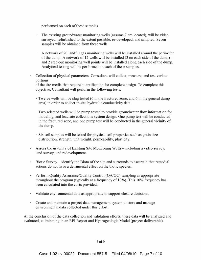
6 of 9
performed on each of these samples. − The existing groundwater monitoring wells (assume 7 are located), will be video
surveyed, refurbished to the extent possible, re-developed, and sampled. Seven samples will be obtained from these wells.
− A network of 20 landfill gas monitoring wells will be installed around the perimeter
of the dump. A network of 12 wells will be installed (3 on each side of the dump) – and 2 step-out monitoring well points will be installed along each side of the dump. Analytical testing will be performed on each of these samples.
• Collection of physical parameters. Consultant will collect, measure, and test various
portions of the site media that require quantification for complete design. To complete this objective, Consultant will perform the following tests:
− Twelve wells will be slug tested (6 in the fractured zone, and 6 in the general dump
area) in order to collect in-situ hydraulic conductivity data. − Two selected wells will be pump tested to provide groundwater flow information for
modeling, and leachate collections system design. One pump test will be conducted in the fractured zone, and one pump test will be conducted in the general vicinity of the dump.
− Six soil samples will be tested for physical soil properties such as grain size
distribution, strength, unit weight, permeability, plasticity.
• Assess the usability of Existing Site Monitoring Wells – including a video survey, land survey, and redevelopment.
• Biotic Survey – identify the Biota of the site and surrounds to ascertain that remedial
actions do not have a detrimental effect on the biotic species.
• Perform Quality Assurance/Quality Control (QA/QC) sampling as appropriate throughout the program (typically at a frequency of 10%). This 10% frequency has been calculated into the costs provided.
• Validate environmental data as appropriate to support closure decisions.
• Create and maintain a project data management system to store and manage
environmental data collected under this effort. At the conclusion of the data collection and validation efforts, these data will be analyzed and evaluated, culminating in an RFI Report and Hydrogeologic Model (project deliverable).
Case 1:02-cv-00022 Document 557-5 Filed 04/08/10 Page 7 of 10

7 of 9
RFI Report:
• RFI Report per RCRA Guidance. Includes Draft, Draft Final, and Final versions as well as responses to Agency Comments. Includes method discussions, data presentation, analysis, findings, and conclusions. A Hydrogeologic Model including 3D visualizations will also be part of the effort.
Groundwater Monitoring:
• Groundwater Monitoring and reporting will be conducted on a quarterly basis for the period of 1 year following the initial installation and sampling of wells. Twenty-seven monitoring wells will be sampled each quarter (the 15 shallow wells, 5 deeper wells, and the 7 existing monitoring wells). The 8 deeper wells associated with the fracture zone study will not be sampled as part of this effort.
Corrective Measures Study:
• A CMS will be prepared to evaluate a range of remedial options available to address the site contaminants. The CMS will borrow heavily from the closure efforts that are currently being planned so as to optimize operational efficiency.
GBB Deliverables/Responsibilities:
• GBB to provide access, permissions, and all right-of-ways necessary to conduct field work and associated project activities.
• GBB to continue to supply Consultant with existing documents as are available. • GBB to supply existing laboratory data as is available. • GBB will assist in obtaining letters of regulatory concurrence for each version of project
documents.
Assumptions:
• Consultant take lead in regulatory review and will obtain letter of regulatory concurrence for each version of project documents
• Some of the existing environmental data are useful for qualitative purposes only.
• None of the existing analytical data are useful for analytical purposes.
• The maximum depth to bedrock is no more than 30 feet from the natural ground surface.
Case 1:02-cv-00022 Document 557-5 Filed 04/08/10 Page 8 of 10

8 of 9
• Initial groundwater encountered at depths of 20 ft. or less below the natural ground
surface.
• Fractured bedrock investigation will not require drilling in the dump footprint or the waste.
• Monitoring wells and/or piezometers will not be required to be installed within the dump foot print, or in the waste.
• Unexploded Ordnance (UXO) and Munitions and Explosives of Concern (MEC), will not be encountered in any field activity. Only UXO avoidance practices will be required.
• Should groundwater contamination exist along the north or east sides of the landfill, this scope of work does not account for the probability that site contaminants have impacted limestone aquifer on the eastern side of the fault. Should that probability arise, such an investigation would be scoped separately in a phased manner, and is not currently included in this scope of work.
• The large fault northeast of the dump (Adelup-Pago Fault) will not require site specific seismic hazard evaluation as part of the RFI or RCRA Closure.
• The presence and proximity of the Adelup-Pago Fault will not require extraordinary design or construction considerations or measures.
• Since securing the RCRA Closure letter will be dependent upon final closure construction activities of the dump, it is assumed that the RCRA closure will be granted at the completion of the entire project and not tied to the RFI.
• Ambient Air will not be a component of the RFI, as the final remedy will include a full cap, and any potential exposure pathways will be eliminated or controlled.
• The regulators will require site clean-up to address all contaminants detected above Ecological Screening Levels, Regional Screening Levels, and Guam Numerical Values. Risk based approaches are not included in this scope of work, however, if found to be locally supported, will be included in this scope of work.
• Water generated from the pump tests and well development efforts can not be used on the
dump for dust control, however does not require treatment, or off-site disposal.
• RFI and associated efforts will require meeting with the regulators approximately once per month.
• Groundwater monitoring efforts for the RFI are anticipated to require only 1 year of quarterly monitoring.
Case 1:02-cv-00022 Document 557-5 Filed 04/08/10 Page 9 of 10
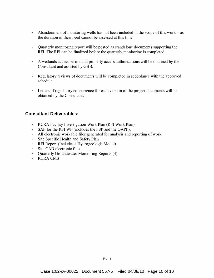
9 of 9
• Abandonment of monitoring wells has not been included in the scope of this work – as
the duration of their need cannot be assessed at this time.
• Quarterly monitoring report will be posted as standalone documents supporting the RFI. The RFI can be finalized before the quarterly monitoring is completed.
• A wetlands access permit and property access authorizations will be obtained by the Consultant and assisted by GBB.
• Regulatory reviews of documents will be completed in accordance with the approved schedule.
• Letters of regulatory concurrence for each version of the project documents will be obtained by the Consultant.
Consultant Deliverables:
• RCRA Facility Investigation Work Plan (RFI Work Plan) • SAP for the RFI WP (includes the FSP and the QAPP). • All electronic workable files generated for analysis and reporting of work • Site Specific Health and Safety Plan • RFI Report (Includes a Hydrogeologic Model) • Site CAD electronic files • Quarterly Groundwater Monitoring Reports (4) • RCRA CMS
Case 1:02-cv-00022 Document 557-5 Filed 04/08/10 Page 10 of 10

Change
Order Description of the Change Reason for Change Amount Added
Days
Added
1 Additional water for dust control
Contract estimates of the amount of water
needed for dust control were inadequate. 54,000.00$ 0
2 Additional rock excavation
Contract estimates of the amount of rock
to be excavated were inadequate. 462,000.00$ 0
3 Additional acres for turf establishment
Contract estimates of the acreage requiring
turf establishment were inadequate. 92,400.00$ 0
4 Additional paved waterway
Contract estimates of the paved waterway
needed were inadequate. 246,180.00$ 0
5 Reduction in grouted rip rap
Contract estimates of the amount of
grouted rip rap needed were excessive. (132,990.00)$ 0
6 Additional rip rap for spillway
Engineer determined the addition needed
to prevent erosion. 36,575.00$ 0
7 Material substitute for embankment work.
The addition of coral and crushed rock
(from the site) will enable work to continue
during wet weather. 620,000.00$ 0
8 Time Extension Weather related delay. -$ 64
9 Temporary Access Roads
Added roads to allow access to monitoring
well sites. 141,060.00$ 21
10 Additional rock excavation
Contract estimates of the amount of rock
to be excavated were inadequate. 1,027,114.00$ 79
Total 2,546,339.00$ 164
Original Contract 8,360,000.00$
Total Contract 10,906,339.00$
Change Orders
Maeda Pacific Corporation Contract
Landfill Operations Road and Mass Grading for Cells 1 & 2
Case 1:02-cv-00022 Document 557-6 Filed 04/08/10 Page 1 of 1
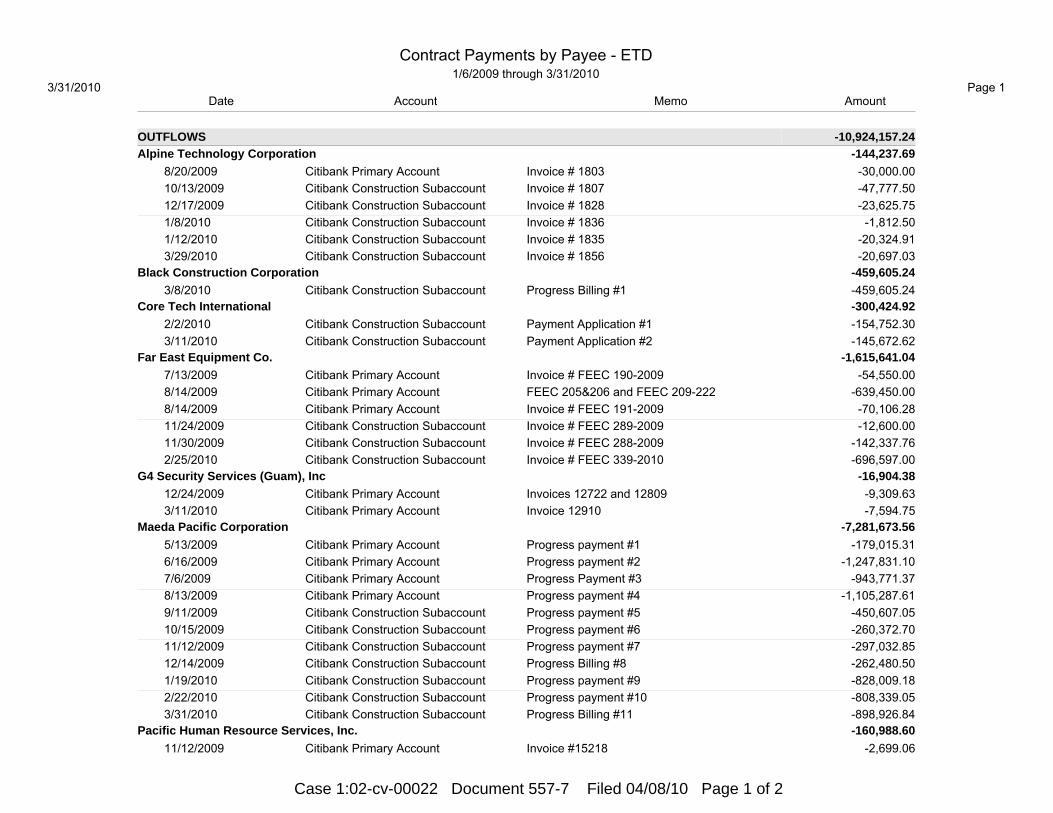
Date Account Memo Amount
OUTFLOWS -10,924,157.24Alpine Technology Corporation -144,237.69 8/20/2009 Citibank Primary Account Invoice # 1803 -30,000.00 10/13/2009 Citibank Construction Subaccount Invoice # 1807 -47,777.50 12/17/2009 Citibank Construction Subaccount Invoice # 1828 -23,625.75 1/8/2010 Citibank Construction Subaccount Invoice # 1836 -1,812.50 1/12/2010 Citibank Construction Subaccount Invoice # 1835 -20,324.91 3/29/2010 Citibank Construction Subaccount Invoice # 1856 -20,697.03Black Construction Corporation -459,605.24 3/8/2010 Citibank Construction Subaccount Progress Billing #1 -459,605.24Core Tech International -300,424.92 2/2/2010 Citibank Construction Subaccount Payment Application #1 -154,752.30 3/11/2010 Citibank Construction Subaccount Payment Application #2 -145,672.62Far East Equipment Co. -1,615,641.04 7/13/2009 Citibank Primary Account Invoice # FEEC 190-2009 -54,550.00 8/14/2009 Citibank Primary Account FEEC 205&206 and FEEC 209-222 -639,450.00 8/14/2009 Citibank Primary Account Invoice # FEEC 191-2009 -70,106.28 11/24/2009 Citibank Construction Subaccount Invoice # FEEC 289-2009 -12,600.00 11/30/2009 Citibank Construction Subaccount Invoice # FEEC 288-2009 -142,337.76 2/25/2010 Citibank Construction Subaccount Invoice # FEEC 339-2010 -696,597.00G4 Security Services (Guam), Inc -16,904.38 12/24/2009 Citibank Primary Account Invoices 12722 and 12809 -9,309.63 3/11/2010 Citibank Primary Account Invoice 12910 -7,594.75Maeda Pacific Corporation -7,281,673.56 5/13/2009 Citibank Primary Account Progress payment #1 -179,015.31 6/16/2009 Citibank Primary Account Progress payment #2 -1,247,831.10 7/6/2009 Citibank Primary Account Progress Payment #3 -943,771.37 8/13/2009 Citibank Primary Account Progress payment #4 -1,105,287.61 9/11/2009 Citibank Construction Subaccount Progress payment #5 -450,607.05 10/15/2009 Citibank Construction Subaccount Progress payment #6 -260,372.70 11/12/2009 Citibank Construction Subaccount Progress payment #7 -297,032.85 12/14/2009 Citibank Construction Subaccount Progress Billing #8 -262,480.50 1/19/2010 Citibank Construction Subaccount Progress payment #9 -828,009.18 2/22/2010 Citibank Construction Subaccount Progress payment #10 -808,339.05 3/31/2010 Citibank Construction Subaccount Progress Billing #11 -898,926.84Pacific Human Resource Services, Inc. -160,988.60 11/12/2009 Citibank Primary Account Invoice #15218 -2,699.06
Contract Payments by Payee - ETD1/6/2009 through 3/31/2010
3/31/2010 Page 1
Case 1:02-cv-00022 Document 557-7 Filed 04/08/10 Page 1 of 2
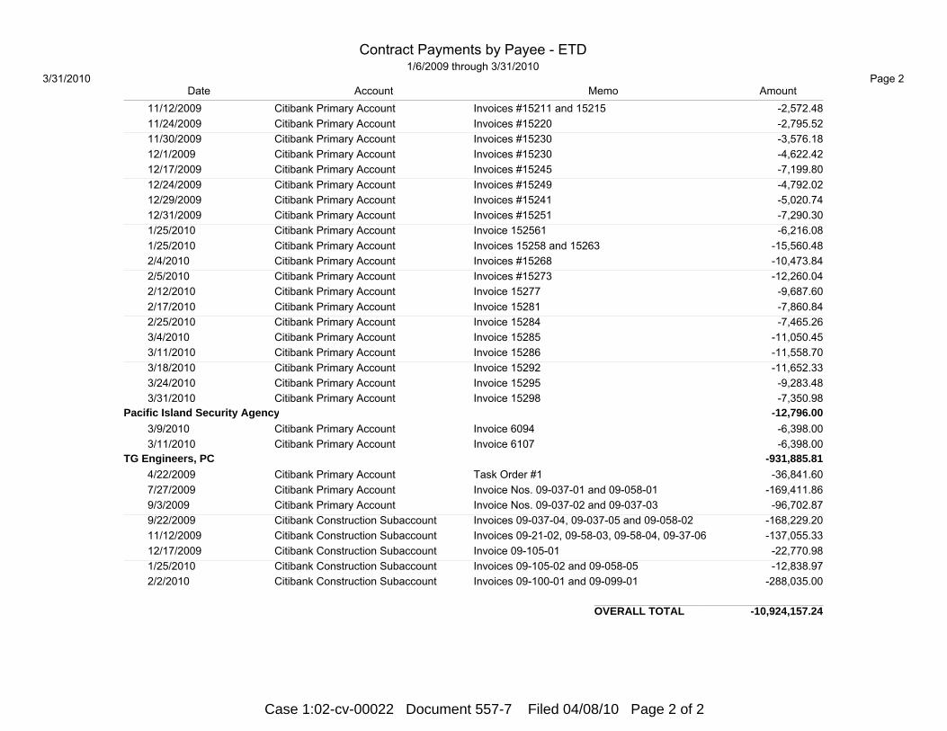
Date Account Memo Amount 11/12/2009 Citibank Primary Account Invoices #15211 and 15215 -2,572.48 11/24/2009 Citibank Primary Account Invoices #15220 -2,795.52 11/30/2009 Citibank Primary Account Invoices #15230 -3,576.18 12/1/2009 Citibank Primary Account Invoices #15230 -4,622.42 12/17/2009 Citibank Primary Account Invoices #15245 -7,199.80 12/24/2009 Citibank Primary Account Invoices #15249 -4,792.02 12/29/2009 Citibank Primary Account Invoices #15241 -5,020.74 12/31/2009 Citibank Primary Account Invoices #15251 -7,290.30 1/25/2010 Citibank Primary Account Invoice 152561 -6,216.08 1/25/2010 Citibank Primary Account Invoices 15258 and 15263 -15,560.48 2/4/2010 Citibank Primary Account Invoices #15268 -10,473.84 2/5/2010 Citibank Primary Account Invoices #15273 -12,260.04 2/12/2010 Citibank Primary Account Invoice 15277 -9,687.60 2/17/2010 Citibank Primary Account Invoice 15281 -7,860.84 2/25/2010 Citibank Primary Account Invoice 15284 -7,465.26 3/4/2010 Citibank Primary Account Invoice 15285 -11,050.45 3/11/2010 Citibank Primary Account Invoice 15286 -11,558.70 3/18/2010 Citibank Primary Account Invoice 15292 -11,652.33 3/24/2010 Citibank Primary Account Invoice 15295 -9,283.48 3/31/2010 Citibank Primary Account Invoice 15298 -7,350.98Pacific Island Security Agency -12,796.00 3/9/2010 Citibank Primary Account Invoice 6094 -6,398.00 3/11/2010 Citibank Primary Account Invoice 6107 -6,398.00TG Engineers, PC -931,885.81 4/22/2009 Citibank Primary Account Task Order #1 -36,841.60 7/27/2009 Citibank Primary Account Invoice Nos. 09-037-01 and 09-058-01 -169,411.86 9/3/2009 Citibank Primary Account Invoice Nos. 09-037-02 and 09-037-03 -96,702.87 9/22/2009 Citibank Construction Subaccount Invoices 09-037-04, 09-037-05 and 09-058-02 -168,229.20 11/12/2009 Citibank Construction Subaccount Invoices 09-21-02, 09-58-03, 09-58-04, 09-37-06 -137,055.33 12/17/2009 Citibank Construction Subaccount Invoice 09-105-01 -22,770.98 1/25/2010 Citibank Construction Subaccount Invoices 09-105-02 and 09-058-05 -12,838.97 2/2/2010 Citibank Construction Subaccount Invoices 09-100-01 and 09-099-01 -288,035.00
OVERALL TOTAL -10,924,157.24
Contract Payments by Payee - ETD1/6/2009 through 3/31/2010
3/31/2010 Page 2
Case 1:02-cv-00022 Document 557-7 Filed 04/08/10 Page 2 of 2

Date Account Description Amount
BALANCE 1/5/2009 0.00 1/6/2009 Citibank Primary Account Deposit By The Government Of Guam 20,000,000.00 1/30/2009 Citibank Primary Account Interest Earned 21,380.84 2/13/2009 Citibank Primary Account Greshman, Brickner & Bratton, Inc -64,828.25 2/27/2009 Citibank Primary Account Interest Earned 23,008.45 3/23/2009 Citibank Primary Account Deposit By The Government Of Guam 3,974,800.00 3/30/2009 Citibank Primary Account Deposit By The Government Of Guam 993,700.00 3/31/2009 Citibank Primary Account Interest Earned 26,816.92 4/6/2009 Citibank Primary Account Deposit By The Government Of Guam 993,700.00 4/13/2009 Citibank Primary Account Deposit By The Government Of Guam 993,700.00 4/22/2009 Citibank Primary Account TG Engineers, PC -36,841.60 4/30/2009 Citibank Primary Account Interest Earned 32,469.17 5/6/2009 Citibank Primary Account District Court Account At The Bank Of Hawaii -993,700.00 5/13/2009 Citibank Primary Account Maeda Pacific Corporation -179,015.31 5/29/2009 Citibank Primary Account Interest Earned 33,162.67 6/16/2009 Citibank Primary Account Maeda Pacific Corporation -1,247,831.10 6/30/2009 Citibank Primary Account Interest Earned 31,080.39 7/6/2009 Citibank Primary Account Maeda Pacific Corporation -943,771.37 7/13/2009 Citibank Primary Account Far East Equipment Co. -54,550.00 7/27/2009 Citibank Primary Account TG Engineers, PC -169,411.86 7/31/2009 Citibank Primary Account Interest Earned 30,274.74 8/13/2009 Citibank Primary Account Maeda Pacific Corporation -1,105,287.61 8/14/2009 Citibank Primary Account Far East Equipment Co. -639,450.00 8/14/2009 Citibank Primary Account Far East Equipment Co. -70,106.28 8/20/2009 Citibank Primary Account Alpine Technology Corporation -30,000.00 8/21/2009 Citibank Primary Account Citibank Construction Subaccount -15,523,734.87 8/28/2009 Citibank Primary Account Linda J. Ibanez -7,766.67 8/31/2009 Citibank Primary Account Interest Earned 21,487.60 9/3/2009 Citibank Primary Account TG Engineers, PC -96,702.87 9/24/2009 Citibank Primary Account Citibank Construction Subaccount 96,702.87 9/28/2009 Citibank Primary Account linda J. Ibanez -7,766.67 9/30/2009 Citibank Primary Account Interest Earned 7,452.01 10/21/2009 Citibank Primary Account District Court Account At The Bank Of Hawaii -1,000,000.00 10/29/2009 Citibank Primary Account Linda J. Ibanez -7,766.67 10/30/2009 Citibank Primary Account Interest Earned 7,087.64 11/12/2009 Citibank Primary Account Pacific Human Resource Services, Inc. -2,699.06 11/12/2009 Citibank Primary Account Depo Resources -1,015.00
Citibank Primary Account - ETD:31/6/2009 through 3/31/2010
3/31/2010 Page 1
Case 1:02-cv-00022 Document 557-8 Filed 04/08/10 Page 1 of 3

Date Account Description Amount 11/12/2009 Citibank Primary Account Shimbros -350.00 11/12/2009 Citibank Primary Account Pacific Human Resource Services, Inc. -2,572.48 11/24/2009 Citibank Primary Account Pacific Human Resource Services, Inc. -2,795.52 11/25/2009 Citibank Primary Account Linda J. Ibanez -7,804.17 11/30/2009 Citibank Primary Account Pacific Human Resource Services, Inc. -3,576.18 11/30/2009 Citibank Primary Account Interest Earned 6,293.70 12/1/2009 Citibank Primary Account Pacific Human Resource Services, Inc. -4,622.42 12/17/2009 Citibank Primary Account Pacific Human Resource Services, Inc. -7,199.80 12/24/2009 Citibank Primary Account Pacific Human Resource Services, Inc. -4,792.02 12/24/2009 Citibank Primary Account G4 Security Services (Guam), Inc -9,309.63 12/29/2009 Citibank Primary Account Linda J. Ibanez -7,766.67 12/29/2009 Citibank Primary Account Pacific Human Resource Services, Inc. -5,020.74 12/31/2009 Citibank Primary Account Pacific Human Resource Services, Inc. -7,290.30 12/31/2009 Citibank Primary Account Interest Earned 1,254.99 1/6/2010 Citibank Primary Account Interest Earned 5,221.49 1/25/2010 Citibank Primary Account Pacific Human Resource Services, Inc. -6,216.08 1/25/2010 Citibank Primary Account Pacific Human Resource Services, Inc. -15,560.48 1/27/2010 Citibank Primary Account Linda J. Ibanez -7,886.67 1/29/2010 Citibank Primary Account Interest Earned 6,435.06 2/4/2010 Citibank Primary Account Pacific Human Resource Services, Inc. -10,473.84 2/5/2010 Citibank Primary Account Pacific Human Resource Services, Inc. -12,260.04 2/12/2010 Citibank Primary Account Pacific Human Resource Services, Inc. -9,687.60 2/17/2010 Citibank Primary Account Pacific Human Resource Services, Inc. -7,860.84 2/19/2010 Citibank Primary Account District Court Account At The Bank Of Hawaii -1,000,000.00 2/25/2010 Citibank Primary Account Pacific Human Resource Services, Inc. -7,465.26 2/26/2010 Citibank Primary Account Linda J. Ibanez -7,766.67 2/26/2010 Citibank Primary Account Interest Earned 5,345.60 3/4/2010 Citibank Primary Account Pacific Human Resource Services, Inc. -11,050.45 3/9/2010 Citibank Primary Account Pacific Island Security Agency -6,398.00 3/11/2010 Citibank Primary Account Pacific Island Security Agency -6,398.00 3/11/2010 Citibank Primary Account G4 Security Services (Guam), Inc -7,594.75 3/11/2010 Citibank Primary Account Pacific Human Resource Services, Inc. -11,558.70 3/18/2010 Citibank Primary Account Pacific Human Resource Services, Inc. -11,652.33 3/24/2010 Citibank Primary Account Pacific Human Resource Services, Inc. -9,283.48 3/29/2010 Citibank Primary Account Linda J. Ibanez -7,766.67 3/31/2010 Citibank Primary Account Pacific Human Resource Services, Inc. -7,350.98 3/31/2010 Citibank Primary Account Interest Earned 5,022.77
1/6/2009 - 3/31/2010 3,906,820.95
Citibank Primary Account - ETD:31/6/2009 through 3/31/2010
3/31/2010 Page 2
Case 1:02-cv-00022 Document 557-8 Filed 04/08/10 Page 2 of 3

Date Account Description Amount
BALANCE 3/31/2010 3,906,820.95
TOTAL INFLOWS 27,316,396.91
TOTAL OUTFLOWS -23,409,575.96
NET TOTAL 3,906,820.95
Citibank Primary Account - ETD:31/6/2009 through 3/31/2010
3/31/2010 Page 3
Case 1:02-cv-00022 Document 557-8 Filed 04/08/10 Page 3 of 3

Date Description Memo Amount
BALANCE 7/30/2009 0.00 7/31/2009 Opening Balance 0.00 8/21/2009 Citibank Construction Subaccount Court order of 8-11-2009 15,523,734.87 8/31/2009 Interest Earned 1,169.64 9/1/2009 Interest Earned 5,850.82 9/11/2009 Maeda Pacific Corporation Progress payment #5 -450,607.05 9/22/2009 TG Engineers, PC Invoices 09-037-04, 09-037-05 and 09-058-02 -168,229.20 9/24/2009 Citibank Construction Subaccount Letter of 9-23-09 -96,702.87 9/30/2009 Interest Earned 18,698.40 10/13/2009 Alpine Technology Corporation Invoice # 1807 -47,777.50 10/15/2009 Maeda Pacific Corporation Progress payment #6 -260,372.70 10/19/2009 Treasurer Of Guam GEPA permit fee -4,548.29 10/30/2009 Interest Earned 18,687.94 11/12/2009 TG Engineers, PC Invoices 09-21-02, 09-58-03, 09-58-04, 09-37-06 -137,055.33 11/12/2009 Maeda Pacific Corporation Progress payment #7 -297,032.85 11/24/2009 Treasurer Of Guam GEPA permit fee -2,544.76 11/24/2009 Far East Equipment Co. Invoice # FEEC 289-2009 -12,600.00 11/30/2009 far East Equipment Co. Invoice # FEEC 288-2009 -142,337.76 11/30/2009 Interest Earned 17,587.32 12/14/2009 Maeda Pacific Corporation Progress Billing #8 -262,480.50 12/17/2009 Alpine Technology Corporation Invoice # 1828 -23,625.75 12/17/2009 TG Engineers, PC Invoice 09-105-01 -22,770.98 12/31/2009 Interest Earned 3,444.01 1/6/2010 Interest Earned Additional interest earnings for 12/31/09 14,136.32 1/8/2010 Alpine Technology Corporation Invoice # 1836 -1,812.50 1/12/2010 Alpine Technology Corporation Invoice # 1835 -20,324.91 1/19/2010 Maeda Pacific Corporation Progress payment #9 -828,009.18 1/25/2010 TG Engineers, PC Invoices 09-105-02 and 09-058-05 -12,838.97 1/29/2010 Interest Earned 16,967.17 2/2/2010 Treasurer Of Guam GEPA permit fee -9,685.32 2/2/2010 Core Tech International Payment Application #1 -154,752.30 2/2/2010 Tg Engineers, PC Invoices 09-100-01 and 09-099-01 -288,035.00 2/22/2010 Maeda Pacific Corporation Progress payment #10 -808,339.05 2/25/2010 Far East Equipment Co. Invoice # FEEC 339-2010 -696,597.00 2/26/2010 Interest Earned 13,920.47 3/8/2010 Black Construction Corporation Progress Billing #1 -459,605.24 3/11/2010 Core Tech International Payment Application #2 -145,672.62
Citibank Construction Subaccount - ETD7/31/2009 through 3/31/2010
3/31/2010 Page 1
Case 1:02-cv-00022 Document 557-9 Filed 04/08/10 Page 1 of 2

Date Description Memo Amount 3/29/2010 Alpine Technology Corporation Invoice # 1856 -20,697.03 3/31/2010 Maeda Pacific Corporation Progress Billing #11 -898,926.84 3/31/2010 Interest Earned 13,257.11
7/31/2009 - 3/31/2010 9,373,472.57
BALANCE 3/31/2010 9,373,472.57
TOTAL INFLOWS 15,647,454.07
TOTAL OUTFLOWS -6,273,981.50
NET TOTAL 9,373,472.57
Citibank Construction Subaccount - ETD7/31/2009 through 3/31/2010
3/31/2010 Page 2
Case 1:02-cv-00022 Document 557-9 Filed 04/08/10 Page 2 of 2
Government of Guam
Department of Public Works, Solid Waste Management Division
542 North Marine Corps Drive, Tamuning, Guam 96913
Phone: (671) 646-4379, Ext. 201 or 212
www.GuamSolidWasteReceiver.org
www.gbbinc.com
February 2, 2010 Mr. Anthony C. Blaz Administrator Guam Economic Development Authority ITC Building, Suite 511 590 South Marine Corps Drive Tamuning, Guam 96913 Dear Mr. Blaz: Thank you for sharing your memo dated January 12, 2009, addressing the Issues raised by the Receiver in our October 21, 2009 Quarterly Report to the District Court. Your memo also acknowledges the additional issues outlined in our January 14, 2010 Quarterly Report and comments on them, as well. We appreciate your work to address these issues and your efforts to work with us to understand our concerns. We have reviewed your memo and want to share with you additional comments with respect to your responses. For the purpose of this letter, we will summarize the aspects of your response upon which we wish to provide additional comment, after which we will state our additional comment. Receiver Issue 1: Refinancing. GEDA states that Sandi Boughton of USDA has verbally clarified that the USDA did not consider the Section 30 bonds issued for the landfill portion of the project as being on "reasonable rates and terms” because USDA determined that
tipping fees could not be collected at rates sufficient to pay landfill operating expenses and debt service on the Section 30 bonds. It is also noted that USDA stated in a letter dated November 27, 2009 that the “tax-exempt bonds obtained by GovGuam was not at reasonable rates and terms”
Additional Receiver Comment: While the somewhat lower interest rate and the grant will reduce the cost of the landfill to its customers, it should be noted that the rates which have been set and are presently being collected, are sufficient to pay the operating expense and debt service of the bonds.
Receiver Issue 2: Applicant Contributions. GEDA states in its response that it understands that all applicant funding must be disbursed prior to any funding from USDA. GEDA further states that $39,874,646 “has been identified and is available for immediate
drawdown to fund the Consent Decree projects”. GEDA also states that the parties have
“verbally agreed to the process and the timing involved” for drawdown of the funds. It is
also noted that USDA “may” accept the projects existing A/E contracts subsequent to a
cursory review.
Case 1:02-cv-00022 Document 557-10 Filed 04/08/10 Page 1 of 4

Government of Guam
Department of Public Works, Solid Waste Management Division
542 North Marine Corps Drive, Tamuning, Guam 96913
Phone: (671) 646-4379, Ext. 201 or 212
www.GuamSolidWasteReceiver.org
www.gbbinc.com
Mr. Anthony C. Blaz February 2, 2010 Page 2
Additional Receiver Comment: The Receiver does not understand the source of the applicant contributions nor have the differences noted in the Court approved capital budget and the USDA project budget been explained. We assume that the source of applicant funding must be the Section 30 bonds that the USDA loan seeks to replace, but this has never been confirmed. We need confirmation of the source of these funds and an explanation of the differences between the Court approved capital budget and the USDA approved project budget. The verbal agreement mentioned on the drawdown of funds must be put into writing. With respect to the contract issue, more than the A/E contracts are involved. Construction contracts are the primary concern and assurance is needed that the contracts are acceptable, not just that they “may” be acceptable.
Receiver Issue 3: Interim Construction Financing. GEDA cites a verbal agreement reached on a conference call with respect to this issue.
Additional Receiver Comment: The agreement with USDA described by GEDA must be put in writing before it can be reasonably evaluated by the Receiver.
Receiver Issue 4: Disbursement Procedures. GEDA cites a verbal agreement with respect to this issue.
Additional Receiver Comment: The agreement described by GEDA must be put in writing before it can be reasonably evaluated by the Receiver.
Receiver Issue 5: Section 30 Security. GEDA states that USDA has agreed to a 5th position lien on Section 30 funds and that this is already authorized by law.
Additional Receiver Comment: The agreement with USDA described by GEDA must be put in writing before it can be reasonably evaluated by the Receiver. The Attorney General will need to confirm that existing law authorizes such a lien.
Receiver Issue 6: Reserves. GEDA cites written clarification for two of the three reserves but describes a verbal agreement with respect to the third reserve.
Additional Receiver Comment: The agreement concerning the Interim Financing Interest Reserve described by GEDA must also be put in writing
Receiver Issue 7: Required Customers. GEDA cites written clarification on this issue that is sufficient from the Receiver’s perspective.
Additional Receiver Comment: It is clear from the comments made by USDA that they expect the Military to be the “large volume user” of the system. The only way to assure that this is accomplished is to enter a binding agreement with the Government prior to the closing of the USDA loan. Clarification is needed about the USDA’s position on this matter.
Case 1:02-cv-00022 Document 557-10 Filed 04/08/10 Page 2 of 4

Government of Guam
Department of Public Works, Solid Waste Management Division
542 North Marine Corps Drive, Tamuning, Guam 96913
Phone: (671) 646-4379, Ext. 201 or 212
www.GuamSolidWasteReceiver.org
www.gbbinc.com
Mr. Anthony C. Blaz February 2, 2010 Page 3
It is also clear that representations have been made to USDA that all of Guam’s
waste, other than that which is recycled using traditional means of recycling, will go to the Layon Landfill. The Government of Guam, however, has taken no steps to implement the control of all waste within its jurisdiction (i.e. known as flow control) to assure that this representation is effective. Does USDA understand this and do they expect the Government to exert its authority to assure that all of Guam’s waste
goes to the Layon Landfill? What is the timing of any such requirement?
Receiver Issue 8: Third Party Management. GEDA states that an RFP is in the development stage for third party management and cites written communication from the USDA stating that the Receiver may participate in the bidding.
Additional Receiver Comment: This evidences a serious misunderstanding by GEDA and USDA of the Receivership. The Order creating the Receivership states: “IT IS FURTHER ORDERED that the Receiver shall have the authority required or
necessary for the complete management and control of the Consent Decree projects,
including but not limited to:
(a) The supervision of all of Government of Guam’s employees associated
with the Consent Decree projects;
(b) The performance of existing contracts;
(c) The entering into future contracts deemed necessary. In awarding any
future contracts, the Receiver shall follow the procedures required in Guam’s
statutes and regulations, unless, in the best judgment of the Receiver, such
compliance would unreasonably delay the progress in meeting the mandates
of the Consent Decree;”
The above provisions of the Court’s Order placing the Solid Waste Management
Division into Receivership places it under the “complete management and control” of
the Receiver. The Court explicitly places the performance of existing contracts and entering into future contracts under the authority of the Receiver. Under the Order, the Receiver is the responsible authority for entering into contracts. As such, neither GEDA nor any other entity has the authority to enter into a contract for third party management of the new landfill independent of the Receiver. Since the Receiver is responsible for the procurement of any contracts relative to solid waste, the Receiver cannot possibly bid on such a contract.
Receiver Issue 9: Operating Budget and Rate Analysis. GEDA states that USDA is to provide acknowledgement documenting that this requirement cannot be complied with until 2011 at the earliest and that non-compliance would not be subject to a default of the loan conditions. GEDA also notes that USDA is currently reviewing the executed contracts for compliance with their requirements, including modifications needed for compliance with the ARRA and Davis-Bacon prevailing wage requirements. It also states that these requirements will be incorporated as needed via amendments to contracts.
Additional Receiver Comment: The described acknowledgement must be provided in writing. In addition, it should be understood that neither the
Case 1:02-cv-00022 Document 557-10 Filed 04/08/10 Page 3 of 4

Government of Guam
Department of Public Works, Solid Waste Management Division
542 North Marine Corps Drive, Tamuning, Guam 96913
Phone: (671) 646-4379, Ext. 201 or 212
www.GuamSolidWasteReceiver.org
www.gbbinc.com
Mr. Anthony C. Blaz February 2, 2010 Page 4
Receiver nor the Government of Guam are in a position to force the contractors to accept contract amendments since these contractors already have valid and binding contracts. Retroactive amendments of this complexity are difficult to effectuate. This is especially true with respect to the Maeda contract, since most of the work under this contract has already been completed.
Receiver Issue 10: Real Property Insurance. GEDA states that USDA will provide the Government of Guam with the amount and type of insurance required.
Additional Receiver Comment: Written confirmation needs to be provided.
Receiver Issue 11: Audit Agreement. GEDA states that these audit services will be the responsibility of the Department of Administration in coordination with the Office of the Public Auditor.
Additional Receiver Comment: This issue is resolved from the Receiver’s
perspective.
Receiver Recommendations: GEDA accurately describes the Receiver’s
recommendations and discussions with GEDA concerning these recommendations and other issues, including the timing of the loan, the Buy American and Davis Bacon requirements, the USDA prohibition of free service and the our concern about GEDA’s consideration of
financing for a private company to build a landfill and waste to energy plant on Guam.
Additional Receiver Comment: We have no additional comments other than those contained in this letter and our Quarterly Report to the District Court dated January 14, 2009.
We look forward to continuing our work with you to assist the Government of Guam in achieving its goals with respect to the USDA Loan/Grant without compromising the vital work of achieving full compliance with the Consent Decree. Thank you. Sincerely, David L. Manning GBB’s Receiver Representative c.c. The Honorable Felix P. Camacho, Governor of Guam The Honorable Alicia G. Limtiaco, Attorney General of Guam
Case 1:02-cv-00022 Document 557-10 Filed 04/08/10 Page 4 of 4

Program Cost FY 2011 FY 2012 FY 2013 FY 2014 FY 2015 FY 2016 FY 2017 FY 2018 FY 2019 FY 2020
Estimated Program Cost and Reserves
Disposal Services 4,228,206$ 4,355,052$ 4,485,704$ 4,620,275$ 4,758,883$ 4,901,650$ 5,048,699$ 5,200,160$ 5,356,165$ 5,516,850$
Residential Services 1,411,110$ 1,453,443$ 1,497,046$ 1,541,958$ 1,588,217$ 1,635,863$ 1,684,939$ 1,735,487$ 1,787,552$ 1,841,178$
Support Services 881,466$ 907,910$ 935,147$ 963,201$ 992,097$ 1,021,860$ 1,052,516$ 1,084,092$ 1,116,614$ 1,150,113$
Debt Service 4,363,374$ 4,363,374$ 9,584,540$ 9,584,311$ 9,582,859$ 9,582,859$ 9,582,546$ 9,584,056$ 9,582,913$ 9,584,158$
Reserve for Equipment Replacement 1,886,492$ 1,943,087$ 2,001,380$ 2,061,421$ 2,123,264$ 2,186,962$ 2,252,571$ 2,320,148$ 2,389,752$ 2,461,445$
Reserve for Closure 677,682$ 677,682$ 698,012$ 718,953$ 740,521$ 762,737$ 785,619$ 561,188$ 578,023$ 595,364$
Reserve for Post Closure Care 480,911$ 480,911$ 495,338$ 510,198$ 525,504$ 541,269$ 557,507$ 574,233$ 591,459$ 609,203$
Reserve for Future Cell Development 4,112,000$ 4,112,000$ 4,235,360$ 4,362,421$ 4,493,293$ 4,628,092$ 2,374,935$ 2,446,183$ 2,519,569$ 2,595,156$
Total Cost and Reserves 18,041,240$ 18,293,459$ 23,932,528$ 24,362,738$ 24,804,638$ 25,261,292$ 23,339,332$ 23,505,545$ 23,922,047$ 24,353,467$
Estimated Revenue
Tipping Fee Revenue 15,179,109$ 17,127,579$ 18,231,618$ 19,350,907$ 17,957,899$ 15,834,484$ 15,252,672$ 15,524,351$ 15,829,438$ 16,112,093$
Residential Collection Revenue 5,759,463$ 5,759,463$ 5,759,463$ 5,759,463$ 5,759,463$ 5,759,463$ 5,759,463$ 5,759,463$ 5,759,463$ 5,759,463$
Transfer Stations (non-commercial) 300,000$ 300,000$ 300,000$ 300,000$ 300,000$ 300,000$ 300,000$ 300,000$ 300,000$ 300,000$
Total Revenue 21,238,572$ 23,187,042$ 24,291,081$ 25,410,370$ 24,017,362$ 21,893,947$ 21,312,135$ 21,583,814$ 21,888,901$ 22,171,556$
Surplus/(Deficit) 3,197,331$ 4,893,583$ 358,553$ 1,047,632$ (787,277)$ (3,367,345)$ (2,027,197)$ (1,921,731)$ (2,033,146)$ (2,181,911)$
Fund Balance
Beginning Fund Balance 3,267,933$ 6,465,265$ 11,358,848$ 11,717,401$ 12,765,033$ 11,977,757$ 8,610,411$ 6,583,215$ 4,661,484$ 2,628,338$
Ending Fund Balance 6,465,265$ 11,358,848$ 11,717,401$ 12,765,033$ 11,977,757$ 8,610,411$ 6,583,215$ 4,661,484$ 2,628,338$ 446,427$
Fees
Commercial Tipping Fees $165.53 $165.53 $165.53 $165.53 $165.53 $165.53 $165.53 $165.53 $165.53 $165.53
Residential Collection Fees $30.00 $30.00 $30.00 $30.00 $30.00 $30.00 $30.00 $30.00 $30.00 $30.00
Transfer Stations (non-commercial) various various various various various various various various various various
Solid Waste Management Division Projected Financial Results
(Excluding the Military as a Customer)
100 Percent Section 30 Backed Bond Financed
Rate Setting Analysis (Spring 2010) 100% Sec 30 FinancingCase 1:02-cv-00022 Document 557-11 Filed 04/08/10 Page 1 of 1

Program Cost FY 2011 FY 2012 FY 2013 FY 2014 FY 2015 FY 2016 FY 2017 FY 2018 FY 2019 FY 2020
Estimated Program Cost and Reserves
Disposal Services 4,228,206$ 4,355,052$ 4,485,704$ 4,620,275$ 4,758,883$ 4,901,650$ 5,048,699$ 5,200,160$ 5,356,165$ 5,516,850$
Residential Services 1,411,110$ 1,453,443$ 1,497,046$ 1,541,958$ 1,588,217$ 1,635,863$ 1,684,939$ 1,735,487$ 1,787,552$ 1,841,178$
Support Services 881,466$ 907,910$ 935,147$ 963,201$ 992,097$ 1,021,860$ 1,052,516$ 1,084,092$ 1,116,614$ 1,150,113$
Debt Service 4,363,374$ 4,363,374$ 9,584,540$ 9,584,311$ 9,582,859$ 9,582,859$ 9,582,546$ 9,584,056$ 9,582,913$ 9,584,158$
Reserve for Equipment Replacement 1,886,492$ 1,943,087$ 2,001,380$ 2,061,421$ 2,123,264$ 2,186,962$ 2,252,571$ 2,320,148$ 2,389,752$ 2,461,445$
Reserve for Closure 806,705$ 806,705$ 830,906$ 855,833$ 881,508$ 907,953$ 706,692$ 727,892$ 749,729$ 772,221$
Reserve for Post Closure Care 480,911$ 480,911$ 495,338$ 510,198$ 525,504$ 541,269$ 557,507$ 574,233$ 591,459$ 609,203$
Reserve for Future Cell Development 5,114,000$ 5,114,000$ 5,267,420$ 5,425,443$ 5,588,206$ 3,196,852$ 3,064,258$ 3,156,185$ 3,250,871$ 3,348,397$
Total Cost and Reserves 19,172,263$ 19,424,481$ 25,097,481$ 25,562,640$ 26,040,537$ 23,975,268$ 23,949,727$ 24,382,252$ 24,825,055$ 25,283,565$
Estimated Revenue
Tipping Fee Revenue 11,933,312$ 16,303,872$ 17,183,074$ 20,436,705$ 20,590,458$ 18,921,100$ 18,463,699$ 18,677,284$ 18,917,133$ 19,139,347$
Residential Collection Revenue 5,184,071$ 5,184,071$ 5,184,071$ 5,184,071$ 5,184,071$ 5,184,071$ 5,184,071$ 5,184,071$ 5,184,071$ 5,184,071$
Transfer Stations (non-commercial) 300,000$ 300,000$ 300,000$ 300,000$ 300,000$ 300,000$ 300,000$ 300,000$ 300,000$ 300,000$
Total Revenue 17,417,383$ 21,787,943$ 22,667,146$ 25,920,777$ 26,074,530$ 24,405,171$ 23,947,770$ 24,161,355$ 24,401,205$ 24,623,418$
Surplus/(Deficit) (1,754,880)$ 2,363,462$ (2,430,335)$ 358,137$ 33,992$ 429,903$ (1,957)$ (220,897)$ (423,851)$ (660,147)$
Fund Balance
Beginning Fund Balance 3,267,933$ 1,513,054$ 3,876,515$ 1,446,180$ 1,804,316$ 1,838,309$ 2,268,212$ 2,266,255$ 2,045,358$ 1,621,507$
Ending Fund Balance 1,513,054$ 3,876,515$ 1,446,180$ 1,804,316$ 1,838,309$ 2,268,212$ 2,266,255$ 2,045,358$ 1,621,507$ 961,360$
Fees
Commercial Tipping Fees $130.14 $130.14 $130.14 $130.14 $130.14 $130.14 $130.14 $130.14 $130.14 $130.14
Residential Collection Fees $27.00 $27.00 $27.00 $27.00 $27.00 $27.00 $27.00 $27.00 $27.00 $27.00
Transfer Stations (non-commercial) various various various various various various various various various various
Solid Waste Management Division Projected Financial Results
(Including the Military as a Customer)
100 Percent Section 30 Backed Bond Financed
Rate Setting Analysis (Spring 2010) 100% Sec 30 FinancingCase 1:02-cv-00022 Document 557-12 Filed 04/08/10 Page 1 of 1

Program Cost FY 2011 FY 2012 FY 2013 FY 2014 FY 2015 FY 2016 FY 2017 FY 2018 FY 2019 FY 2020
Estimated Program Cost and Reserves
Disposal Services 4,228,206$ 4,355,052$ 4,485,704$ 4,620,275$ 4,758,883$ 4,901,650$ 5,048,699$ 5,200,160$ 5,356,165$ 5,516,850$
Residential Services 1,411,110$ 1,453,443$ 1,497,046$ 1,541,958$ 1,588,217$ 1,635,863$ 1,684,939$ 1,735,487$ 1,787,552$ 1,841,178$
Support Services 881,466$ 907,910$ 935,147$ 963,201$ 992,097$ 1,021,860$ 1,052,516$ 1,084,092$ 1,116,614$ 1,150,113$
Debt Service 1,213,052$ 1,213,052$ 7,187,179$ 7,102,693$ 7,017,867$ 6,933,445$ 6,848,936$ 6,764,934$ 6,680,195$ 6,596,119$
Reserve for Equipment Replacement 1,886,492$ 1,943,087$ 2,001,380$ 2,061,421$ 2,123,264$ 2,186,962$ 2,252,571$ 2,320,148$ 2,389,752$ 2,461,445$
Reserve for Closure 677,682$ 677,682$ 698,012$ 718,953$ 740,521$ 762,737$ 785,619$ 561,188$ 578,023$ 595,364$
Reserve for Post Closure Care 480,911$ 480,911$ 495,338$ 510,198$ 525,504$ 541,269$ 557,507$ 574,233$ 591,459$ 609,203$
Reserve for Future Cell Development 4,112,000$ 4,112,000$ 4,235,360$ 4,362,421$ 4,493,293$ 4,628,092$ 2,374,935$ 2,446,183$ 2,519,569$ 2,595,156$
Total Cost and Reserves 14,890,919$ 15,143,137$ 21,535,166$ 21,881,120$ 22,239,647$ 22,611,878$ 20,605,722$ 20,686,424$ 21,019,329$ 21,365,427$
Estimated Revenue
Tipping Fee Revenue 13,149,363$ 14,837,284$ 15,793,692$ 16,763,310$ 15,556,574$ 13,717,102$ 13,213,090$ 13,448,440$ 13,712,731$ 13,957,589$
Residential Collection Revenue 5,191,766$ 5,191,766$ 5,191,766$ 5,191,766$ 5,191,766$ 5,191,766$ 5,191,766$ 5,191,766$ 5,191,766$ 5,191,766$
Transfer Stations (non-commercial) 300,000$ 300,000$ 300,000$ 300,000$ 300,000$ 300,000$ 300,000$ 300,000$ 300,000$ 300,000$
Total Revenue 18,641,129$ 20,329,050$ 21,285,458$ 22,255,076$ 21,048,340$ 19,208,867$ 18,704,856$ 18,940,206$ 19,204,497$ 19,449,355$
Surplus/(Deficit) 3,750,211$ 5,185,914$ (249,708)$ 373,956$ (1,191,307)$ (3,403,011)$ (1,900,867)$ (1,746,218)$ (1,814,832)$ (1,916,073)$
Fund Balance
Beginning Fund Balance 3,267,933$ 7,018,144$ 12,204,058$ 11,954,349$ 12,328,306$ 11,136,999$ 7,733,988$ 5,833,121$ 4,086,903$ 2,272,071$
Ending Fund Balance 7,018,144$ 12,204,058$ 11,954,349$ 12,328,306$ 11,136,999$ 7,733,988$ 5,833,121$ 4,086,903$ 2,272,071$ 355,998$
Fees
Commercial Tipping Fees $143.40 $143.40 $143.40 $143.40 $143.40 $143.40 $143.40 $143.40 $143.40 $143.40
Residential Collection Fees $27.04 $27.04 $27.04 $27.04 $27.04 $27.04 $27.04 $27.04 $27.04 $27.04
Transfer Stations (non-commercial) various various various various various various various various various various
Solid Waste Management Division Projected Financial Results
(Excluding the Military as a Customer)
USDA and Section 30 Backed Bond Financed
Rate Setting Analysis (Spring 2010) USDA and Sec 30 Bond Financing 3-28-10Case 1:02-cv-00022 Document 557-13 Filed 04/08/10 Page 1 of 1

Program Cost FY 2011 FY 2012 FY 2013 FY 2014 FY 2015 FY 2016 FY 2017 FY 2018 FY 2019 FY 2020
Estimated Program Cost and Reserves
Disposal Services 4,228,206$ 4,355,052$ 4,485,704$ 4,620,275$ 4,758,883$ 4,901,650$ 5,048,699$ 5,200,160$ 5,356,165$ 5,516,850$
Residential Services 1,411,110$ 1,453,443$ 1,497,046$ 1,541,958$ 1,588,217$ 1,635,863$ 1,684,939$ 1,735,487$ 1,787,552$ 1,841,178$
Support Services 881,466$ 907,910$ 935,147$ 963,201$ 992,097$ 1,021,860$ 1,052,516$ 1,084,092$ 1,116,614$ 1,150,113$
Debt Service 1,213,052$ 1,213,052$ 7,187,179$ 7,102,693$ 7,017,867$ 6,933,445$ 6,848,936$ 6,764,934$ 6,680,195$ 6,596,119$
Reserve for Equipment Replacement 1,886,492$ 1,943,087$ 2,001,380$ 2,061,421$ 2,123,264$ 2,186,962$ 2,252,571$ 2,320,148$ 2,389,752$ 2,461,445$
Reserve for Closure 806,705$ 806,705$ 830,906$ 855,833$ 881,508$ 907,953$ 706,692$ 727,892$ 749,729$ 772,221$
Reserve for Post Closure Care 480,911$ 480,911$ 495,338$ 510,198$ 525,504$ 541,269$ 557,507$ 574,233$ 591,459$ 609,203$
Reserve for Future Cell Development 5,114,000$ 5,114,000$ 5,267,420$ 5,425,443$ 5,588,206$ 3,196,852$ 3,064,258$ 3,156,185$ 3,250,871$ 3,348,397$
Total Cost and Reserves 16,021,941$ 16,274,159$ 22,700,119$ 23,081,022$ 23,475,546$ 21,325,854$ 21,216,118$ 21,563,131$ 21,922,337$ 22,295,526$
Estimated Revenue
Tipping Fee Revenue 10,364,119$ 14,159,964$ 14,923,554$ 17,749,343$ 17,882,878$ 16,433,034$ 16,035,780$ 16,221,279$ 16,429,590$ 16,622,583$
Residential Collection Revenue 4,734,776$ 4,734,776$ 4,734,776$ 4,734,776$ 4,734,776$ 4,734,776$ 4,734,776$ 4,734,776$ 4,734,776$ 4,734,776$
Transfer Stations (non-commercial) 300,000$ 300,000$ 300,000$ 300,000$ 300,000$ 300,000$ 300,000$ 300,000$ 300,000$ 300,000$
Total Revenue 15,398,895$ 19,194,739$ 19,958,330$ 22,784,118$ 22,917,653$ 21,467,810$ 21,070,556$ 21,256,055$ 21,464,365$ 21,657,358$
Surplus/(Deficit) (623,047)$ 2,920,580$ (2,741,790)$ (296,903)$ (557,893)$ 141,956$ (145,562)$ (307,076)$ (457,972)$ (638,168)$
Fund Balance
Beginning Fund Balance 3,267,933$ 2,644,887$ 5,565,467$ 2,823,677$ 2,526,774$ 1,968,881$ 2,110,837$ 1,965,275$ 1,658,199$ 1,200,227$
Ending Fund Balance 2,644,887$ 5,565,467$ 2,823,677$ 2,526,774$ 1,968,881$ 2,110,837$ 1,965,275$ 1,658,199$ 1,200,227$ 562,059$
Fees
Commercial Tipping Fees $113.02 $113.02 $113.02 $113.02 $113.02 $113.02 $113.02 $113.02 $113.02 $113.02
Residential Collection Fees $24.66 $24.66 $24.66 $24.66 $24.66 $24.66 $24.66 $24.66 $24.66 $24.66
Transfer Stations (non-commercial) various various various various various various various various various various
Solid Waste Management Division Projected Financial Results
(Including the Military as a Customer)
USDA and Section 30 Backed Bond Financed
Rate Setting Analysis (Spring 2010) USDA and Sec 30 Bond Financing 3-28-10Case 1:02-cv-00022 Document 557-14 Filed 04/08/10 Page 1 of 1

Actual Solid Waste Delivered to the Ordot DumpWeekly June 1, 2009 Forward
Description
Commercial Solid Waste (Compacted) 752,751 lb 564,860 lb 816,460 lb 714,580 lb 638,700 lb
Commercial Solid Waste (Non-Compacted) 1,045,520 lb 963,420 lb 1,167,760 lb 1,170,940 lb 1,198,000 lb
Agat Transfer Station (Non-Compacted) 24,160 lb 25,300 lb 25,960 lb 25,460 lb 29,780 lb
Dededo Transfer Station (Non-Compacted) 61,760 lb 89,120 lb 79,960 lb 75,360 lb 70,880 lb
Malojloj Transfer Station (Non-Compacted) 22,720 lb 11,300 lb 19,780 lb 20,800 lb 13,260 lb
Ordot Transfer Station (Non-Compacted) 43,020 lb 43,840 lb 35,700 lb 43,720 lb 56,900 lb
Mayors' Solid Waste (Non-Compacted) 47,740 lb 33,080 lb 63,640 lb 49,540 lb 55,620 lb
GovGuam Solid Waste (Non-Compacted) 240,240 lb 60,560 lb 104,840 lb 160,780 lb 116,440 lb
Residential Packer Trucks SWMD 703,980 lb 655,940 lb 711,000 lb 721,640 lb 709,360 lb
Grand Total: 2,941,891 lb 2,447,420 lb 3,025,100 lb 2,982,820 lb 2,888,940 lb
Weekly Tons of MSW 1,471 1,224 1,513 1,491 1,444
Average Daily Tons of MSW 245 204 252 249 241
Projected Annual Tons of MSW 76,489 63,633 78,653 77,553 75,112
Cover Material-DPW 2,604,449 lb 2,286,220 lb 2,337,260 lb 2,214,620 lb 2,119,420 lb
Non DPW Cover Material 405,920 lb 382,740 lb 833,780 lb 719,960 lb 1,220,100 lb
Total Cover material 3,010,369 lb 2,668,960 lb 3,171,040 lb 2,934,580 lb 3,339,520 lb
Cover % of MSW 102% 109% 105% 98% 116%
Grand Total 5,952,260 lb 5,116,380 lb 6,196,140 lb 5,917,400 lb 6,228,460 lb
Net Wt. Net Wt. Net Wt. Net Wt.
6/22 to 6/27
Net Wt.
6/29 to 7/46/1 to 6/6 6/8 to 6/13 6/15 to 6/20
Page 1 of 9Case 1:02-cv-00022 Document 557-15 Filed 04/08/10 Page 1 of 9

Actual Solid Waste Delivered to the Ordot DumpWeekly June 1, 2009 Forward
Description
Commercial Solid Waste (Compacted)
Commercial Solid Waste (Non-Compacted)
Agat Transfer Station (Non-Compacted)
Dededo Transfer Station (Non-Compacted)
Malojloj Transfer Station (Non-Compacted)
Ordot Transfer Station (Non-Compacted)
Mayors' Solid Waste (Non-Compacted)
GovGuam Solid Waste (Non-Compacted)
Residential Packer Trucks SWMD
Grand Total:
Weekly Tons of MSW
Average Daily Tons of MSW
Projected Annual Tons of MSW
Cover Material-DPW
Non DPW Cover Material
Total Cover material
Cover % of MSW
Grand Total
706,680 lb 677,520 lb 697,119 lb 726,600 lb 775,840 lb
1,299,080 lb 1,315,380 lb 1,236,846 lb 1,351,040 lb 1,485,080 lb
26,760 lb 35,600 lb 31,660 lb 34,260 lb 32,940 lb
78,900 lb 96,500 lb 90,840 lb 72,400 lb 99,540 lb
22,340 lb 24,900 lb 20,600 lb 24,420 lb 22,740 lb
60,300 lb 61,260 lb 55,520 lb 55,260 lb 59,020 lb
74,460 lb 71,280 lb 52,260 lb 51,480 lb 87,280 lb
40,000 lb 28,520 lb 60,360 lb 42,400 lb 47,360 lb
768,300 lb 778,460 lb 753,220 lb 765,960 lb 830,540 lb
3,076,820 lb 3,089,420 lb 2,998,425 lb 3,123,820 lb 3,440,340 lb
1,538 1,545 1,499 1,562 1,720
256 257 250 260 287
79,997 80,325 77,959 81,219 89,449
2,935,660 2,396,460 lb 1,341,420 lb 1,296,140 lb 1,987,340 lb
578,640 266,420 lb 448,860 lb 1,458,180 lb 271,680 lb
3,514,300 2,662,880 lb 1,790,280 lb 2,754,320 lb 2,259,020 lb
114% 86% 60% 88% 66%
6,591,120 5,752,300 lb 4,788,705 lb 5,878,140 lb 5,699,360 lb
Net Wt. Net Wt.
8/3 to 8/87/6 to 7/11
Net Wt.
7/13 to 7/18 7/27 to 8/1
Net Wt. Net Wt.
7/20 to 7/25
Page 2 of 9Case 1:02-cv-00022 Document 557-15 Filed 04/08/10 Page 2 of 9

Actual Solid Waste Delivered to the Ordot DumpWeekly June 1, 2009 Forward
Description
Commercial Solid Waste (Compacted)
Commercial Solid Waste (Non-Compacted)
Agat Transfer Station (Non-Compacted)
Dededo Transfer Station (Non-Compacted)
Malojloj Transfer Station (Non-Compacted)
Ordot Transfer Station (Non-Compacted)
Mayors' Solid Waste (Non-Compacted)
GovGuam Solid Waste (Non-Compacted)
Residential Packer Trucks SWMD
Grand Total:
Weekly Tons of MSW
Average Daily Tons of MSW
Projected Annual Tons of MSW
Cover Material-DPW
Non DPW Cover Material
Total Cover material
Cover % of MSW
Grand Total
861,760 lb 792,640 lb 766,880 lb 684,300 lb 736,120 lb
1,393,060 lb 1,425,220 lb 1,344,520 lb 1,291,420 lb 1,306,520 lb
39,260 lb 24,560 lb 31,440 lb 32,220 lb 27,700 lb
89,540 lb 98,100 lb 93,160 lb 86,660 lb 78,020 lb
28,220 lb 18,520 lb 32,960 lb 30,940 lb 22,220 lb
70,040 lb 82,480 lb 65,300 lb 71,700 lb 46,140 lb
63,340 lb 61,800 lb 64,320 lb 54,440 lb 89,000 lb
64,200 lb 44,640 lb 77,480 lb 51,300 lb 78,460 lb
797,680 lb 767,680 lb 759,260 lb 748,300 lb 753,380 lb
3,407,100 lb 3,315,640 lb 3,235,320 lb 3,051,280 lb 3,137,560 lb
1,704 1,658 1,618 1,526 1,569
284 276 270 254 261
88,585 86,207 84,118 79,333 81,577
1,954,780 lb 2,020,020 lb 2,890,160 lb 2,892,300 lb 1,793,517 lb
577,660 lb 177,340 lb 64,960 lb 121,580 lb 0 lb
2,532,440 lb 2,197,360 lb 2,955,120 lb 3,013,880 lb 1,793,517 lb
74% 66% 91% 99% 57%
5,939,540 lb 5,513,000 lb 6,190,440 lb 6,065,160 lb 4,931,077 lb
8/24 to 8/29
Net Wt.
8/17 to 8/22
Net Wt.
8/10 to 8/15 8/31 to 9/5
Net Wt. Net Wt.
9/7 to 9/12
Net Wt.
Page 3 of 9Case 1:02-cv-00022 Document 557-15 Filed 04/08/10 Page 3 of 9

Actual Solid Waste Delivered to the Ordot DumpWeekly June 1, 2009 Forward
Description
Commercial Solid Waste (Compacted)
Commercial Solid Waste (Non-Compacted)
Agat Transfer Station (Non-Compacted)
Dededo Transfer Station (Non-Compacted)
Malojloj Transfer Station (Non-Compacted)
Ordot Transfer Station (Non-Compacted)
Mayors' Solid Waste (Non-Compacted)
GovGuam Solid Waste (Non-Compacted)
Residential Packer Trucks SWMD
Grand Total:
Weekly Tons of MSW
Average Daily Tons of MSW
Projected Annual Tons of MSW
Cover Material-DPW
Non DPW Cover Material
Total Cover material
Cover % of MSW
Grand Total
689,900 lb 748,400 lb 758,760 lb 783,020 lb 703,060 lb
1,190,560 lb 1,389,900 lb 1,395,100 lb 1,303,540 lb 1,142,420 lb
25,960 lb 27,340 lb 36,380 lb 30,920 lb 31,440 lb
100,520 lb 83,500 lb 119,020 lb 91,940 lb 86,820 lb
26,960 lb 25,960 lb 24,980 lb 24,360 lb 23,360 lb
55,860 lb 65,020 lb 84,740 lb 61,440 lb 63,720 lb
68,800 lb 55,980 lb 57,660 lb 46,540 lb 63,500 lb
38,300 lb 73,380 lb 61,740 lb 79,180 lb 51,560 lb
727,080 lb 765,900 lb 755,860 lb 801,040 lb 657,620 lb
2,923,940 lb 3,235,380 lb 3,294,240 lb 3,221,980 lb 2,823,500 lb
1,462 1,618 1,647 1,611 1,412
244 270 275 268 235
76,022 84,120 85,650 83,771 73,411
1,962,140 lb 4,368,680 lb 2,476,380 lb 2,521,880 lb 2263320 lb
0 lb - lb 176,540 lb 578,420 lb 469260 lb
1,962,140 lb 4,368,680 lb 2,652,920 lb 3,100,300 lb 2,732,580 lb
67% 135% 81% 96% 97%
4,886,080 lb 7,604,060 lb 5,947,160 lb 6,322,280 lb 5,556,080 lb
9/21 to 9/26
Net Wt.
9/28 to 10/03
Net Wt.
10/12 to 10/17
Net Wt.
10/5 to 10/10
Net Wt.
9/14 to 9/19
Net Wt.
Page 4 of 9Case 1:02-cv-00022 Document 557-15 Filed 04/08/10 Page 4 of 9

Actual Solid Waste Delivered to the Ordot DumpWeekly June 1, 2009 Forward
Description
Commercial Solid Waste (Compacted)
Commercial Solid Waste (Non-Compacted)
Agat Transfer Station (Non-Compacted)
Dededo Transfer Station (Non-Compacted)
Malojloj Transfer Station (Non-Compacted)
Ordot Transfer Station (Non-Compacted)
Mayors' Solid Waste (Non-Compacted)
GovGuam Solid Waste (Non-Compacted)
Residential Packer Trucks SWMD
Grand Total:
Weekly Tons of MSW
Average Daily Tons of MSW
Projected Annual Tons of MSW
Cover Material-DPW
Non DPW Cover Material
Total Cover material
Cover % of MSW
Grand Total
763,560 lb 781,360 lb 732,840 lb 715,760 lb 713,300 lb
1,293,420 lb 1,343,900 lb 1,321,340 lb 1,248,900 lb 1,223,580 lb
32,820 lb 27,160 lb 31,460 lb 32,600 lb 23,480 lb
87,440 lb 89,580 lb 99,340 lb 84,460 lb 80,460 lb
27,300 lb 20,780 lb 31,160 lb 16,080 lb 21,160 lb
51,160 lb 60,960 lb 72,100 lb 55,020 lb 59,600 lb
52,400 lb 68,860 lb 56,320 lb 35,140 lb 57,640 lb
65,680 lb 5,500 lb 54,860 lb 64,280 lb 117,720 lb
744,360 lb 741,480 lb 788,120 lb 722,200 lb 740,680 lb
3,118,140 lb 3,139,580 lb 3,187,540 lb 2,974,440 lb 3,037,620 lb
1,559 1,570 1,594 1,487 1,519
260 262 266 248 253
81,072 81,629 82,876 77,335 78,978
2,643,220 lb 2,789,640 lb 2,380,200 lb 2,167,820 lb 3,143,420 lb
0 lb - lb 298,640 lb 67,120 lb 35,100 lb
2,643,220 lb 2,789,640 lb 2,678,840 lb 2,234,940 lb 3,178,520 lb
85% 89% 84% 75% 105%
5,761,360 lb 5,929,220 lb 5,866,380 lb 5,209,380 lb 6,216,140 lb
11/16 to 11/21
Net Wt.
11/2 to 11/7
Net Wt.
11/9 to 11/14
Net Wt.
10/19 to 10/24
Net Wt.
10/26 to 10/31
Net Wt.
Page 5 of 9Case 1:02-cv-00022 Document 557-15 Filed 04/08/10 Page 5 of 9
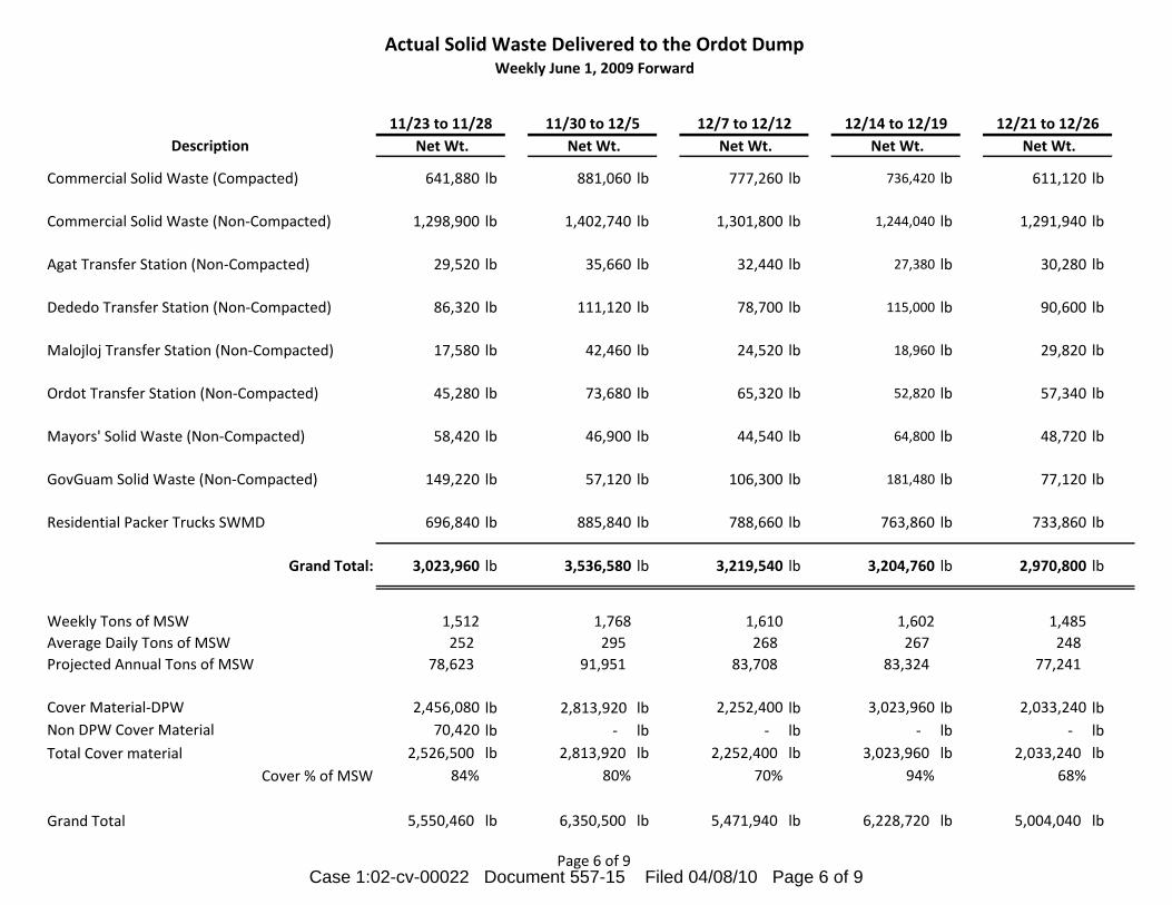
Actual Solid Waste Delivered to the Ordot DumpWeekly June 1, 2009 Forward
Description
Commercial Solid Waste (Compacted)
Commercial Solid Waste (Non-Compacted)
Agat Transfer Station (Non-Compacted)
Dededo Transfer Station (Non-Compacted)
Malojloj Transfer Station (Non-Compacted)
Ordot Transfer Station (Non-Compacted)
Mayors' Solid Waste (Non-Compacted)
GovGuam Solid Waste (Non-Compacted)
Residential Packer Trucks SWMD
Grand Total:
Weekly Tons of MSW
Average Daily Tons of MSW
Projected Annual Tons of MSW
Cover Material-DPW
Non DPW Cover Material
Total Cover material
Cover % of MSW
Grand Total
641,880 lb 881,060 lb 777,260 lb 736,420 lb 611,120 lb
1,298,900 lb 1,402,740 lb 1,301,800 lb 1,244,040 lb 1,291,940 lb
29,520 lb 35,660 lb 32,440 lb 27,380 lb 30,280 lb
86,320 lb 111,120 lb 78,700 lb 115,000 lb 90,600 lb
17,580 lb 42,460 lb 24,520 lb 18,960 lb 29,820 lb
45,280 lb 73,680 lb 65,320 lb 52,820 lb 57,340 lb
58,420 lb 46,900 lb 44,540 lb 64,800 lb 48,720 lb
149,220 lb 57,120 lb 106,300 lb 181,480 lb 77,120 lb
696,840 lb 885,840 lb 788,660 lb 763,860 lb 733,860 lb
3,023,960 lb 3,536,580 lb 3,219,540 lb 3,204,760 lb 2,970,800 lb
1,512 1,768 1,610 1,602 1,485
252 295 268 267 248
78,623 91,951 83,708 83,324 77,241
2,456,080 lb 2,813,920 lb 2,252,400 lb 3,023,960 lb 2,033,240 lb
70,420 lb - lb - lb - lb - lb
2,526,500 lb 2,813,920 lb 2,252,400 lb 3,023,960 lb 2,033,240 lb
84% 80% 70% 94% 68%
5,550,460 lb 6,350,500 lb 5,471,940 lb 6,228,720 lb 5,004,040 lb
11/30 to 12/5
Net Wt.
11/23 to 11/28
Net Wt.
12/7 to 12/12
Net Wt.
12/14 to 12/19
Net Wt.
12/21 to 12/26
Net Wt.
Page 6 of 9Case 1:02-cv-00022 Document 557-15 Filed 04/08/10 Page 6 of 9

Actual Solid Waste Delivered to the Ordot DumpWeekly June 1, 2009 Forward
Description
Commercial Solid Waste (Compacted)
Commercial Solid Waste (Non-Compacted)
Agat Transfer Station (Non-Compacted)
Dededo Transfer Station (Non-Compacted)
Malojloj Transfer Station (Non-Compacted)
Ordot Transfer Station (Non-Compacted)
Mayors' Solid Waste (Non-Compacted)
GovGuam Solid Waste (Non-Compacted)
Residential Packer Trucks SWMD
Grand Total:
Weekly Tons of MSW
Average Daily Tons of MSW
Projected Annual Tons of MSW
Cover Material-DPW
Non DPW Cover Material
Total Cover material
Cover % of MSW
Grand Total
766,040 lb 783,080 lb 754,320 lb 797,160 lb 731,860 lb
1,391,860 lb 1,354,360 lb 1,328,880 lb 1,339,540 lb 1,300,440 lb
41,780 lb 46,820 lb 29,100 lb 36,820 lb 30,460 lb
92,640 lb 80,540 lb 98,180 lb 93,160 lb 100,740 lb
43,520 lb 22,800 lb 17,860 lb 23,940 lb 22,820 lb
93,320 lb 60,700 lb 54,360 lb 50,940 lb 55,620 lb
52,880 lb 48,620 lb 47,440 lb 37,280 lb 47,620 lb
82,760 lb 107,840 lb 24,360 lb 8,740 lb 41,880 lb
903,240 lb 867,700 lb 770,920 lb 762,080 lb 744,840 lb
3,468,040 lb 3,372,460 lb 3,125,420 lb 3,149,660 lb 3,076,280 lb
1,734 1,686 1,563 1,575 1,538
289 281 260 262 256
90,169 87,684 81,261 81,891 79,983
1,259,660 lb 1,442,360 lb 2,027,080 lb 2,027,080 lb 2,581,020 lb
20,220 lb - lb - lb - lb - lb
1,279,880 lb 1,442,360 lb 2,027,080 lb 2,027,080 lb 2,581,020 lb
37% 43% 65% 64% 84%
4,747,920 lb 4,814,820 lb 5,152,500 lb 5,176,740 lb 5,657,300 lb
12/28 to 1/2
Net Wt.
1/4 to 1/9
Net Wt.
1/18 to 1/23
Net Wt.
1/11 to 1/16
Net Wt.
1/25 to 1/30
Net Wt.
Page 7 of 9Case 1:02-cv-00022 Document 557-15 Filed 04/08/10 Page 7 of 9

Actual Solid Waste Delivered to the Ordot DumpWeekly June 1, 2009 Forward
Description
Commercial Solid Waste (Compacted)
Commercial Solid Waste (Non-Compacted)
Agat Transfer Station (Non-Compacted)
Dededo Transfer Station (Non-Compacted)
Malojloj Transfer Station (Non-Compacted)
Ordot Transfer Station (Non-Compacted)
Mayors' Solid Waste (Non-Compacted)
GovGuam Solid Waste (Non-Compacted)
Residential Packer Trucks SWMD
Grand Total:
Weekly Tons of MSW
Average Daily Tons of MSW
Projected Annual Tons of MSW
Cover Material-DPW
Non DPW Cover Material
Total Cover material
Cover % of MSW
Grand Total
702,460 lb 677,220 lb 714,260 lb 681,000 lb 729,640 lb
1,248,140 lb 1,246,760 lb 1,259,080 lb 1,265,720 lb 1,271,100 lb
22,800 lb 29,580 lb 22,440 lb 28,580 lb 24,280 lb
78,760 lb 74,480 lb 89,460 lb 80,100 lb 79,600 lb
20,620 lb 25,100 lb 24,560 lb 26,180 lb 21,260 lb
46,740 lb 46,100 lb 45,760 lb 40,960 lb 51,200 lb
39,940 lb 41,800 lb 43,340 lb 45,440 lb 31,920 lb
186,500 lb 166,620 lb 371,820 lb 182,360 lb 160,140 lb
747,800 lb 712,980 lb 697,680 lb 710,140 lb 738,340 lb
3,093,760 lb 3,020,640 lb 3,268,400 lb 3,060,480 lb 3,107,480 lb
1,547 1,510 1,634 1,530 1,554
258 252 272 255 259
80,438 78,537 84,978 79,572 80,794
2,680,720 lb 2,590,720 lb 2,005,500 lb 2,100,820 lb 2,078,200 lb
- lb - lb lb lb lb
2,680,720 lb 2,590,720 lb 2,005,500 lb 2,100,820 lb 2,078,200 lb
87% 86% 61% 69% 67%
5,774,480 lb 5,611,360 lb 5,273,900 lb 5,161,300 lb 5,185,680 lb
2/8 to 2/13
Net Wt.
2/15 to 2/20
Net Wt.
2/22 to 2/27
Net Wt.
2/1 to 2/6
Net Wt.
3/1 to 3/6
Net Wt.
Page 8 of 9Case 1:02-cv-00022 Document 557-15 Filed 04/08/10 Page 8 of 9
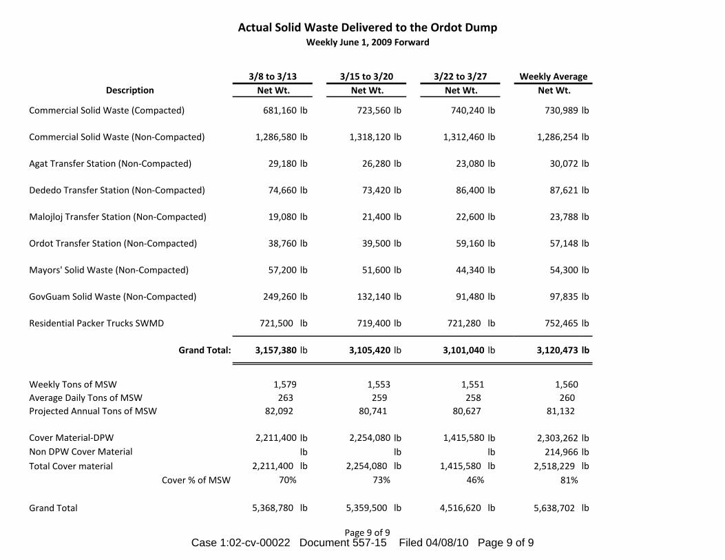
Actual Solid Waste Delivered to the Ordot DumpWeekly June 1, 2009 Forward
Description
Commercial Solid Waste (Compacted)
Commercial Solid Waste (Non-Compacted)
Agat Transfer Station (Non-Compacted)
Dededo Transfer Station (Non-Compacted)
Malojloj Transfer Station (Non-Compacted)
Ordot Transfer Station (Non-Compacted)
Mayors' Solid Waste (Non-Compacted)
GovGuam Solid Waste (Non-Compacted)
Residential Packer Trucks SWMD
Grand Total:
Weekly Tons of MSW
Average Daily Tons of MSW
Projected Annual Tons of MSW
Cover Material-DPW
Non DPW Cover Material
Total Cover material
Cover % of MSW
Grand Total
681,160 lb 723,560 lb 740,240 lb 730,989 lb
1,286,580 lb 1,318,120 lb 1,312,460 lb 1,286,254 lb
29,180 lb 26,280 lb 23,080 lb 30,072 lb
74,660 lb 73,420 lb 86,400 lb 87,621 lb
19,080 lb 21,400 lb 22,600 lb 23,788 lb
38,760 lb 39,500 lb 59,160 lb 57,148 lb
57,200 lb 51,600 lb 44,340 lb 54,300 lb
249,260 lb 132,140 lb 91,480 lb 97,835 lb
721,500 lb 719,400 lb 721,280 lb 752,465 lb
3,157,380 lb 3,105,420 lb 3,101,040 lb 3,120,473 lb
1,579 1,553 1,551 1,560
263 259 258 260
82,092 80,741 80,627 81,132
2,211,400 lb 2,254,080 lb 1,415,580 lb 2,303,262 lb
lb lb lb 214,966 lb
2,211,400 lb 2,254,080 lb 1,415,580 lb 2,518,229 lb
70% 73% 46% 81%
5,368,780 lb 5,359,500 lb 4,516,620 lb 5,638,702 lb
3/8 to 3/13
Net Wt.
Weekly Average
Net Wt.
3/15 to 3/20
Net Wt.
3/22 to 3/27
Net Wt.
Page 9 of 9Case 1:02-cv-00022 Document 557-15 Filed 04/08/10 Page 9 of 9

1
DRAFT AGREEMENT
For Provision of Solid Waste Disposal Services
By Guam Government to the US Navy
THIS SOLID WASTE DISPOSAL “AGREEMENT” made and entered into this XX day of XXXX, 201X, (the “Effective Date”), and is made by and between the COMMANDER NAVFAC REGION M MARIANAS (COMNAVRED), NAVAL FACILITIES ENGINEERING COMMAND MARIANAS, (NAVFAC). GERSHMAN, BRICKNER & BRATTON, INC. FOR THE DISTRICT COURT OF GUAM, TERRITORY OF GUAM (RECEIVER) and the GOVERNMENT OF GUAM (GOVGUAM).
SECTION 1. INTRODUCTION
The purpose of this AGREEMENT is to establish the terms for waste disposal by NAVFAC and associated U.S. Department of Defense organizations in the Layon Municipal Solid Waste Landfill (“LMSWL”) or Transfer Station (“TS”) and to establish a frame-work for mutual cooperation in the management of waste as defined in this AGREEMENT. Prior Agreement. On July 17, 2009, the parties signed a LETTER Of INTENT (“LOI”) in which they formalized their intention to develop this AGREEMENT; once executed, this AGREEMENT will replace the LOI.
SECTION 2. DEFINITIONS
1. Definitions of Waste – a. Acceptable Waste - The following types of waste are acceptable for
disposal under this AGREEMENT: i. Non-hazardous Solid Waste, and ii. Special Waste
as defined in Attachment A- Permit to Operate the LMSWL issued by GUAM Environmental Protection Agency (“GUAM EPA”), and Attachment B - Book 4, Operations Plan, Appendix B, as well as any other waste material described in the Permit to Operate issued by the GUAM EPA.
b. Unacceptable Waste - Regulated hazardous waste, polychlorinated biphenyls (PCB), and any other material described in the current version of the Permit to Operate as defined in Attachment A- Permit to Operate the LMSWL issued by GUAM EPA, and Attachment B - Book 4, Operations Plan, Appendix B. GOVGUAM and NAVFAC agree to separately operate programs to enforce the exclusion of Unacceptable Waste from their respective collection systems so as to minimize the potential for disposal of Unacceptable Waste in the LMSWL.
2. Other Definitions.
a. Closure - Actions taken by the owner or operator of a Solid Waste facility
to cease accepting waste at the site in its entirety or in some portion of the site and to close in conformance with applicable regulations at the time for such closures and to prepare the site, or portion of the site for the post-closure period.
Case 1:02-cv-00022 Document 557-16 Filed 04/08/10 Page 1 of 9

2
b. Commercial Solid Waste - Solid Waste generated by retail and commercial
facilities, offices, restaurants, warehouses, residential dwellings of five or more units, hotels and other facilities for temporary housing, crew quarters, camp grounds, picnic areas, day use recreation areas, other non-manufacturing activities, and institutions including schools, colleges, and other governmental functions of various types.
c. Construction and Demolition Waste – Waste consisting of building
materials, packaging, and rubble resulting from construction, remodeling, repair, and demolition operations of houses, buildings, factories, institutions, and other structures.
d. Disposal- The placing for final disposition of any Solid Waste into the
LMSWL in accordance with conditions of the Permit to Operate issued by Guam EPA shall be considered acceptable disposal. Placing for final disposition Solid Waste in any other facility (other than those operated by the NAVFAC) shall not be considered acceptable disposal and will not meet the terms of this AGREEMENT.
e. Guam Public Utilities Commission (PUC) – The independent regulatory
commission, which regulates the rate and rates impacting procurements of the Guam Power Authority, Guam Waterworks Authority, the Department of Public Works' Division of Solid Waste Management and the Guam municipal golf course.
f. Household Hazardous Waste (HHW) - Waste products which exhibit
characteristics for reactivity, ignitability, corrosivity, or toxicity, as defined by the Resource Conservation and Recovery Act (RCRA), as amended, as hazardous waste, but are generated by households. Examples include, but are not limited to, drain cleaners, latex and oil paint, motor oil, antifreeze, fuel, poisons, pesticides, herbicides and rodenticides, fluorescent lamps, lamp ballasts, smoke detectors, medical waste, some types of cleaning chemicals, and consumer electronics (such as televisions, computers, and cell phones). HHW may be disposed of in the LMSWL if such disposal is in compliance with the requirements of the RCRA.
g. Household Waste - Any Solid Waste (including garbage, trash, and
sanitary waste in septic tanks) generated by households of single- and multiple-residences of up to four units.
h. Industrial Solid Waste - Solid Waste generated by manufacturing or
industrial processes that is not a hazardous waste regulated under Subtitle C of the RCRA or Guam's Hazardous Waste Management regulations.
i. Integrated Solid Waste Management Plan (Plan) - The set of objectives
and approaches to reach them regarding solid waste management and recycling authorized by Guam Law and promulgated by the Guam EPA.
j. Municipal Solid Waste Landfill (MSWLF) unit - A discrete area of land or an
excavation that receives Household Waste, and that is not a land application unit, surface impoundment, injection well, or waste pile, as
Case 1:02-cv-00022 Document 557-16 Filed 04/08/10 Page 2 of 9

3
those terms are defined in 40 CFR 257.2. A Municipal Solid Waste landfill may also receive other types of RCRA Subtitle D wastes, such as Commercial Solid Waste, nonhazardous sludge, and Industrial Solid Waste.
k. Post-Closure Care – Activities of monitoring and management of a MSWLF
after closure has been completed to ensure environmental safety for at least a 30- year period after closure has occurred or such period as applicable law and regulations shall require.
l. Recycled Material- A material that is used in the place of a primary, raw or
virgin material in manufacturing a product m. Recycling - The process by which materials are recovered from Solid
Waste for use in new products and materials.
n. Reuse- The use of a material or item for a second or subsequent use similar to that for which the material or item was originally intended.
o. Scavenging - The action of a person or person(s) removing materials from
loads of Acceptable Waste delivered to the LMSWL or TS for their own personal benefit, on an informal basis and not as a contracted or organized activity at the LMSWL or TS.
p. Solid Waste - Any garbage, refuse, sludge from a wastewater treatment
plant, water supply treatment plant, or air pollution control facility and other discarded material, including solid, liquid, semi-solid, or contained gaseous material resulting from industrial, commercial, mining, and agricultural operations, and from community activities, but does not include solid or dissolved materials in domestic sewage, or solid or dissolved material in irrigation return flows or industrial discharges that are point sources subject to permit under 33 US.C. 1342, or source, special nuclear, or by-product materials as defined by the Atomic Energy Act of 1954, as amended (68 Stat. 923)
q. Solid Waste Management - The systematic administration of activities that provide for the collection, source separation, storage, transportation, transfer, processing, treatment, and disposal of Solid Waste, including the recovery and recycling of materials from Solid Waste.
r. Tipping Fees - Fees charged to dispose of or deposit Solid Waste in a
LMSWLF unit or TS. The tipping fee under this AGREEMENT shall be assessed and calculated on a per ton basis.
s. Transfer Station - An intermediate waste facility in which Solid Waste collected from any source is temporarily deposited and stored while awaiting transportation to another Solid Waste Management facilityfor Disposal.
t. Waste Reduction – The act of reducing the amount or type of waste generated.
Case 1:02-cv-00022 Document 557-16 Filed 04/08/10 Page 3 of 9

4
SECTION 3. COMMODITY AND SERVICES
1. Responsible Agency. GOVGUAM agrees to pursue development and implementation of an Authority that will function to plan, manage, finance, and operate or cause to be operated the LMSWLF or TS, and all other elements of the Solid Waste disposal system under the control of the Receiver as of January 1, 2010. The Authority shall be governed in substantially the same manner as the Guam Water Works Authority and shall have its rates governed by the Guam Public Utilities Commission. GOVGUAM agrees, upon the creation and commencement of operation of the Authority, to assign and convey all rights for fixed and non-fixed assets used to provide Solid Waste Management services including the LMSWLF, TS, and all other proposed and actual elements of the Solid Waste Management system to the Authority.
2. Services To Be Provided. a. Disposal Services. GOVGUAM, acting through the Authority created
pursuant to Section 3, Item 1 and the RECEIVER agree to provide for NAVFAC disposal of Acceptable Waste in the LSMLF under the Terms of this AGREEMENT. Materials not meeting the definition and terms of Acceptable Waste may not be delivered to the LMSWL.
b. Transfer Station. GOVGUAM, acting through the Authority created pursuant to Section 3, Item 1 and the REICEIVER agree to provide access to a properly constructed and permitted TS, and NAVFAC shall have rights to deliver its Acceptable Waste to this TS.
3. Operational Schedule. GOVGUAM, acting through the Authority created pursuant
to Section 3, Item 1 and the RECEIVER agree to develop and implement an operational schedule that will allow deliveries of Acceptable Waste at the LMSWL consistent with Operations Plan, Book 4, including Section 5.1 and 7.0, and at the TS during business hours of a minimum of 8:00 am to 4:00 pm, Monday through Friday, holidays excepted. Holidays and other conditions that will provide for closing of the LMSWL shall also apply and cause the closing of the TS.
4. No Scavenging Policy. GOVGUAM, acting through the Authority created pursuant
to Section 3, Item 1 and the RECEIVER agree to develop, implement, and enforce a policy to prohibit Scavenging at the LMSWL and at the TS. Such requirements shall be included in any contract with any private contractor(s) engaged to operate either of the LMSWL or the TS and shall apply to GOVGUAM’s
and contractors’ employees, agents, and subcontractors, and also shall apply to
all other persons. 5. Method of Delivery of Waste. All Solid Waste shall be consolidated prior to
delivery to the LMSWL. GOVGUAM, acting through the Authority created pursuant to Section 3, Item 1 and the RECEIVER may, in their sole discretion, allow vehicles direct access to the LMSWL if such direct access is determined to be in the best interests of maintaining an effective and efficient Solid Waste Management system. Any Special Waste for which acceptance program(s) are implemented shall be delivered in accordance with adopted operating procedures of the LMSWL and/or the TS.
6. Other Programs . GOVGUAM, acting through the Authority created pursuant to
Section 3, Item 1 and the RECEIVER agrees to develop and implement, on an
Case 1:02-cv-00022 Document 557-16 Filed 04/08/10 Page 4 of 9

5
ongoing basis, appropriate Waste Reduction, Reuse, and Recycling programs. GOVGUAM and NAVFAC agree to explore participation by NAVFAC in these programs but acknowledge that participation by NAVFAC in such programs is not required.
7. Rights to Military Programs. GOVGUAM shall not have any rights or control over
material recovery facilities, Waste Reduction or Reuse programs, Recycling programs, waste collection programs, or ancillary programs operated by NAVFAC and the costs and revenues associated with them.
8. Construction and Demolition Waste. GOVGUAM agrees that NAVFAC shall
maintain control over disposal of Construction and Demolition Waste generated by military installations on Guam and associated Solid Waste landfills operated by military installations during the Term of this AGREEMENT. GOVGUAM, acting through the Authority created pursuant to Section 3, Item 1 and the RECEIVER and NAVFAC agree to explore, Reuse, Recycling, or other alternate uses or disposal options for certain Construction and Demolition Waste or materials.
SECTION 4. SCOPE AND DURATION OF AGREEMENT
1. Agreement Term. The Initial Term (“Initial Term”) of this AGREEMENT shall be _________ years (the maximum time permitted under applicable DOD regulations) from the date Acceptable Waste is first accepted for disposal at the LMSWL or TS. GOVGUAM, acting through the Authority created pursuant to Section 3, Item 1 and the RECEIVER agree to provide disposal services to NAVFAC and NAVFAC agrees to utilize these services in accordance with the applicable Tipping Fees, rules, and regulations as approved by the applicable governing regulatory body and as set forth in this AGREEMENT. Notwithstanding the foregoing, if GOVGUAM has not established and implemented the Authority described in Section 3, item 1 of this AGREEMENT at the time the Receivership is terminated by the District Court of Guam, NAVFAC shall have the right to terminate this AGREEMENT with thirty (30) days’ written notice.
2. Agreement Extension. All other conditions of this AGREEMENT must be met
during the Initial Term as a condition to execute an extension as described in this AGREEMENT. AGREEMENT extension periods will be for no less than __ years in duration (the maximum time permitted under applicable DOD regulations), and will become effective automatically unless either GOVGUAM or NAVFAC notifies the other party no less than 180 days prior to the renewal date of its intention not to extend the AGREEMENT.
3. Maintenance of Existing Military Landfills. NAVFAC intends to maintain its
current waste disposal facilities in open status for disposal services to be used for disposal of Construction and Demolition Waste or Acceptable Waste if the LMSWL is unavailable due to a Force Majeure event or if GOVGUAM fails to meet all requirements in this AGREEMENT.
4. It is expressly understood that neither GOVGUAM nor NAVFAC is under any
obligation to continue any service under the terms and conditions of this AGREEMENT beyond the expiration date.
Case 1:02-cv-00022 Document 557-16 Filed 04/08/10 Page 5 of 9

6
5. GOVGUAM agrees to provide NAVFAC, through certified mail service with the
USPS or by hand delivery to NAVFAC’s designated Contract Officer, one complete set of rates, terms, and conditions of service which are in effect as of the date of this AGREEMENT and any subsequently approved rates as the Guam Public Utilities Commission may authorize, and GOVGUAM agrees to continue furnishing service under this AGREEMENT in accordance with the amended tariff, and NAVFAC agrees to pay for such service at authorized rates as of the date when such rates are made effective.
6. Starting Date of Services Under This AGREEMENT. The start date of disposal
services shall be no later than 60 days after the LMSWL commences commercial operation. GOVGUAM shall provide NAVFAC written notice of the specific start date.
7. Default By GOVGUAM. GOVGUAM will be in default of this AGREEMENT for
suspension of disposal services, unless suspension is the result of a Force Majeure event as defined by this AGREEMENT. NAVFAC agrees to notify GOVGUAM if any incident of default occurs and to allow GOVGUAM 30 days to provide a cure for default or demonstration of a plan to cure with a schedule mutually agreed upon by GOVGUAM and NAVFAC.
8. Fees. Fees for disposal services will be as set by the Guam Public Utilities
Commission and remain in effect until revised pursuant to the regulatory process of the Guam Public Utilities Commission.
a. Disposal fees charged NAVFAC pursuant to this AGREEMENT and set by
the Guam Public Utilities will be the same as fees charged to commercial customers of the LMSWL or TS.
b. GOVGUAM agrees to give NAVFAC written notice of (1) the filing of an
application for change in rates or terms and conditions of service concurrently with the filing of the application and (2) any changes pending with the Guam Public Utilities Commission as of the date of this AGREEMENT.
c. In the event that a regulatory body promulgates any regulation
concerning matters other than rates which affects this AGREEMENT, upon becoming aware of such regulation GOVGUAM shall promptly provide a copy to NAVFAC. NAVFAC shall not be bound to accept any new regulation inconsistent with applicable laws or regulations.
d. In the event NAVFAC delivers Unacceptable Waste to GOVGUAM, GOV
GUAM or its contractor will separate out such waste and dispose of it in appropriate facilities or return it to NAVFAC. NAVFAC agrees to pay GOVGUAM’s cost of the separation, return and/or disposal of such Unacceptable Waste.
9. LMSWL or TS Contractor. GOVGUAM agrees to conduct a competitive procurement process(es) to select the fully qualified contractor(s) for operation of the LMSWL and of the TS, and further, to impose requirements on said contractor(s) to ensure the environmental and technical compliance
Case 1:02-cv-00022 Document 557-16 Filed 04/08/10 Page 6 of 9

7
with the LMSWL and TS permits issued by GUAM EPA, operated in accordance with applicable Guam and federal laws, regulations, and permit requirements, and to enter into contract(s) with the selected contractor(s). Prior to expiration of the initial contract(s) entered into for this purpose, GOVGUAM agrees to conduct a competitive procurement(s) for a replacement contractor(s) for operation of the LMSWL and of the TS. This procurement process will be repeated as needed to ensure qualified private contract operations of the LMSWL and TS during the Initial Term of this AGREEMENT, including all extensions beyond the Initial Term of this AGREEMENT.
10. Access for Compliance Observation. GOVGUAM agrees to, and will include in
each contract for the operation of the LMSWL and TS, complete access by GOVGUAM, the RECEIVER, and NAVFAC to observe operations of the contractor without notice to ensure compliance with the contract and with this AGREEMENT.
11. Scale House. GOVGUAM shall retain ownership and operation of the scale
house at the LMSWL and TS and such operation(s) shall be subject to an annual audit conducted by an independent third party. GOVGUAM agrees to provide for routine scale certification at the LMSWL and TS, the latter when implemented, in compliance with Guam regulation and in addition, to provide for one additional certification by a third party at the same frequency required by Guam regulations. If the scales are not working properly or are being tested, GOVGUAM shall estimate the quantity of waste delivered on the basis of truck volumes and historical information about NAVFAC or its designated Haulers. These estimates shall take the place of actual weighing records during the scale outage and will be the basis of NAVFAC’s payment for waste
delivered to the LMSWL or TS during the outages.
12. Revenue Fund. GOVGUAM agrees to set up a fund to receive all revenue (the “Revenue Fund”) from Solid Waste Management services provided to NAVFAC, other customers, and GOVGUAM. GOVGUAM agrees to appoint a trustee organization that meets fiduciary requirements of GOVGUAM to manage and maintain the Revenue Fund. Should this provision be determined by bond counsel to be in conflict with the terms of any applicable bond indenture, the terms of the applicable bond indenture shall be controlling.
13. Reserve Fund. GOVGUAM and the RECEIVER agree to set up a fund to receive
monies budgeted for reserves (the “Reserve Fund”) for equipment
replacement, closure of cells and of the entire LMSWL, Post-Closure Care to respond to regulatory requirements, and any cell construction costs to be funded from the operating budget. This Reserve Fund shall be managed by the same trustee managing the Revenue Fund. Should this provision be determined by bond counsel to be in conflict with the terms of any applicable bond indenture, the terms of the applicable bond indenture shall be controlling.
14. Force Majeure. No party shall be liable for any failure to perform its
obligations under this AGREEMENT where such failure is as a result of Acts of Nature (including fire, flood, earthquake, storm, typhoon or other natural disaster), war, invasion, act of foreign enemies, hostilities (whether war is declared or not), civil war, rebellion, revolution, insurrection, military or usurped power or confiscation, terrorist activities, nationalization, government
Case 1:02-cv-00022 Document 557-16 Filed 04/08/10 Page 7 of 9

8
sanction, blockage, embargo, labor dispute, strike, lockout or interruption or failure of electricity, and no party will have a right to terminate this AGREEMENT under Clause (Termination) in such circumstances.
Any party asserting Force Majeure as an excuse shall have the burden of proving that reasonable steps were taken (under the circumstances) to minimize delay or damages caused by foreseeable events, that all non-excused obligations were substantially fulfilled, and that the other party was timely notified of the likelihood or actual occurrence which would justify such an assertion, so that other prudent precautions could be taken.
SECTION 5. GENERAL CONDITIONS
1. Compliance with Applicable Laws and Regulations. GOVGUAM agrees to maintain the LMSWL and TS in full compliance with all applicable United States and GOVGUAM laws and regulations.
2. Exclusive Use. NAVFAC agrees to use GOVGUAM’s LMSWL or TS for all
Acceptable Waste requiring disposal during all times when GOVGUAM’s LMSWL and TS are accepting waste and in compliance with this AGREEMENT. Placing for final disposition of Solid Waste in any other facility (other than those operated by the NAVFAC) will not meet the terms of this AGREEMENT.
3. Ownership of Waste. Acceptable Waste being delivered to the LMSWL or TS, shall
become the property of GOVGUAM once it is delivered and accepted by the LMSWL or TS operator.
4. Notices. The respective addresses for each party to receive any notice required
under this AGREEMENT are:
a. GOVGUAM: b. NAVFAC: c. RECEIVER: Gershman, Brickner & Bratton, Inc., 8550 Arlington
Boulevard, Suite 304, Arlington, Virginia 22031 Any party may specify a different address or contact by serving notice of such change to the other parties.
5. Conflicts. The terms of this AGREEMENT shall prevail over any inconsistent or
conflicting terms of any exhibit or attachment to this AGREEMENT. 6. Headings or Titles. The headings or titles preceding each Section or Paragraph or
Subparagraph are for identification purposes only. They shall not be construed as conferring any substantive contract right or duty on any party
7. Applicable Law. This is a Federal AGREEMENT. It shall be interpreted and
enforced under the rules, regulations, laws and policies of the United States only. This AGREEMENT is subject to federal court jurisdiction only.
8. No Joint Venture. Nothing in this AGREEMENT will make, or be construed to
make, the parties hereto partners or joint venturers. Nothing in this AGREEMENT
Case 1:02-cv-00022 Document 557-16 Filed 04/08/10 Page 8 of 9

9
shall render, or be construed to render, any of the parties liable to any third party for debts or obligations of the other parties hereto.
IN WITNESS WHEREOF, the parties hereto have executed this AGREEMENT, as of the day and year first above written.
_________________________________ COMNAVREG
Date: ____________________________ _________________________________ NAVFAC
Date: ___________________________
_________________________________
RECEIVER
Date: ____________________________
_________________________________ FELIX P. CAMACHO
Governor of Guam
Date: ____________________________
Case 1:02-cv-00022 Document 557-16 Filed 04/08/10 Page 9 of 9


![Construction Management Plan Management Plan N203 - Forensic Pathology and Coroner’s Court Construction Management Plan Watpac Construction Project Rev: [1] – …](https://img.pdfslide.net/doc/110x75/5b362f787f8b9a6b548e2417/construction-management-management-plan-n203-forensic-pathology-and-coroners.jpg)