Embed Size (px)
Citation preview
CONSTRUCTION OF A GSM BASED
HOME AUTOMATION USING AVR
BY
OKORAFOR CHINED HENRY
EE/2008/281
DEPARTMENT OF ELECTRICAL AND ELECTRONIC ENGINEERING
FACULTY OF ENGINEERING
CARITAS UNIVERSITY
AMORJI-NIKE, ENUGU.
AUGUST, 2013.
P a g e | i
TITLTE PAGE
A GSM BASED HOME AUTOMATION USING
AVR
BY
OKORAFOR CHINEDU HENRY
EE/2008/281
BEING A PROJECT SUBMITTED TO THE
DEPARTMENT OF ELECTRICAL AND ELECTRONIC ENGINEERING
FACULTY OF ENGINEERING
CARITAS UNIVERSITY AMORJI-NIKE, ENUGU
IN PARTIAL FULFILLMENT OF THE REQUIREMENTS FOR THE
BACHELOR OF ENGINEERING (B.ENG) IN ELECTRICAL AND
ELECTRONIC ENGINEERING
AUGUST, 2013.
P a g e | ii
CERTIFICATION
This is to certify that this project research work from the department of
Electrical/Electronic Engineering, Caritas University, Amorji-Nike, Emene, Enugu
was solely carried out by OKORAFOR CHINEDU HENRY with Registration
Number EE/2008/281
_________________________ ______________________
Engr. E. C. Aneke Date
(Supervisor)
_________________________ _______________________
Engr. C. O. Ejimofor Date
(Head of Department)
_________________________ ______________________
Date
(EXTERNAL EXAMINER)
P a g e | iii
DEDICATION
This report is dedicated to God Almighty who is the ultimate giver of wisdom and
to my beloved parents for their financial support and encouragement throughout
my stay in school.
P a g e | iv
ACKNOWLEDGEMENT
I wish to express my profound thanks and appreciation to God for his unending
mercy, blessing and protection throughout this period. A tree cannot make forests,
without some special people this project may not work well for us. This is why I’m
pleased to acknowledge the following people;
My head of department, Engr. C. O. Ejimofor, My project supervisor, Engr. E. C.
Aneke, and Engr. Augustine Able Ndubuisi (The director of Able Design &
Construction Company) for their moral contribution, corrections and support.
P a g e | v
ABSTRACT
With advancement of technology things are becoming simpler and easier for us.
Automatic systems are being preferred over manual system. The purpose of this
project is to design and construct A GSM based home automation using AVR.
Using GSM networks, in this project a home power control system has been
proposed that will act as an embedded system which can monitor and control
appliances and other devices locally using built-in input and output peripherals.
The system has a delay of 2 minutes after the first call to initiate the next
command. This project is made up of four vital units. These units are as follows:
GSM module unit, peripheral interface control (PIC) unit, driver unit and a power
monitoring and control unit. The GSM module is a GSM transceiver which gives
the system access to the GSM service provider. The peripheral interface control
(PIC) is programmed to carry out the OFF/ RESET operation according to the
GSM commands while the driver and control unit consist of capacitors, resistors,
diodes, regulators and electromagnetic relay is to effect power switching. The
major component that performed the power control of 220v main supply and the
automatic voltage regulation (AVR) is the automated electromagnetic relay. The
project was realized.
P a g e | vi
TABLE OF CONTENT
Title page- - - - - - - - - - -i
Certification page- - - - - - - - - -ii
Dedication- - - - - - - - - - -iii
Acknowledgement- - - - - - - - -iv
Abstract- - - - - - - - - - -v
Table of content- - - - - - - - - -vi
CHAPTER ONE: INTRODUCTION
1.1 Introduction To The Project- - - - - - -1
1.2 Background Of Study- - - - - - - -2
1.3 Problem Statement- - - - - - - - -3
1.4 Aims And Objectives- - - - - - - -4
1.5 Scopes And Purpose Of System Specification- - - - -5
1.6 Limitations- - - - - - - - - -6
CHAPTER TWO: LITERATURE REVIEW
2.1 Review of Related Works- - - - - - -9
2.2 Home Automation System- - - - - - - -9
2.3 Brief History of Tone Recognition Device-- - - - -11
2.4 History of Home Automation- - - - - - -12
P a g e | vii
2.4.1 The Mechanical Evolution- - - - - - -13
2.4.2 The Electrical Evolution- - - - - - - -14
2.4.3 The Information Revolution- - - - - - -15
2.5 Smart Home Today- - - - - - - - -16
2.6 Aspects of Automation Speech Recognition (ASR) Device- - -18
CHAPTER THREE: SYSTEM ANALYSIS AND METHODOLOGY
3.1 Hardware Subsystem- - - - - - - -22
3.2 System Analysis- - - - - - - - -23
3.3 Regulation Unit- - - - - - - - -28
3.4 The Power Supply - - - - - - - - -30
3.5 The Microcontroller- - - - - - - - -30
3.6 The System Flow Chart- - - - - - - -31
CHAPTER FOUR: CONSTRUCTION AND COMPONENT LIST
4.1 Construction- - - - - - - - - -37
4.2 Constructional Methods- - - - - - - -37
4.3 Power Supply Unit (PSU)- - - - - - - -38
4.3 Mounting of Components- - - - - - - -40
4.4 Interconnection of Components- - - - - - -40
4.6 Bill of Engineering Materials and Evaluation (BEME)- - -42
P a g e | viii
CHAPTER FIVE: RECOMMENDATION, CONCLUSION AND
CONSTRAINTS
5.1 Conclusion- - - - - - - - - -44
5.2 Recommendation- - - - - - - - -44
5.3 Major Constraint- - - - - - - - -45
5.4 Constraint Consideration- - - - - - - -45
5.5 Technology Consideration- - - - - - - -46
REFERENCE- - - - - - - - - -47
P a g e | 1
CHAPTER ONE
1.1 INTRODUCTION TO THE PROJECT
With advancement of technology things are becoming simpler and easier for
us. Automation is the use of control systems and information technologies to
reduce the need for human work in the production of goods and services. In the
scope of industrialization, automation is a step beyond mechanization. Whereas
mechanization provided human operators with machinery to assist them with
the muscular requirements of work, automation greatly decreases the need for
human sensory and mental requirements as well. Automation plays an
increasingly important role in the world economy and in daily experience.
Automatic systems are being preferred over manual system. Through this
project we have tried to show automatic control of a house as a result of which
power is saved to some extent. GSM based home automation using AVR is an
electronic device that allows a GSM cell phone to monitor and shut down
electrical power supply at home where there are emergency or ugly situations
such as fire outbreak, lightning strikes, switching surges, transients, neutral
failure and other abnormal conditions or malfunctions that can destroy lives
and properties.
P a g e | 2
GSM based home automation using AVR is a system that implements the
emerging applications of the GSM technology which enable the users to carry
out some task from anywhere in the world via a GSM network, and the system
will automatically regulates power surge. The system is made up of a GSM
amplifier unit, PIC12f629 microcontroller, power control and a power supply
unit. These sub circuits are designed using passive and active electronic
components like capacitors, resistors, diode, regulators, transistors,
electromagnetic relay, microcontroller and battery.
1.2 BACKGROUND OF STUDY
The new age of technology has redefined communication. Most people nowadays
have access to mobile phones and thus the world indeed has become a global
village. At any given moment, any particular individual can be contacted with the
mobile phone. But the application of mobile phone cannot just be restricted to
sending SMS or starting conversations. New innovations and ideas can be
generated from it that can further enhance its capability.
Technologies such as Infra-red, Bluetooth, etc which has developed in recent
years goes to show the very fact that improvements are in fact possible and these
improvements have eased our life and the way we live. Remote management of
several home and office appliances is a subject of growing interest and in recent
P a g e | 3
years we have seen many systems providing such controls. An appliance of a
certain location is eliminated with the use of our system. These days, apart from
supporting voice calls a mobile phone can be used to send text messages as well
as multimedia messages (that may contain pictures, graphics, animations, etc).
Sending written text messages is very popular among mobile phone users. Instant
messaging, as it is also known, allows quick transmission of short messages that
allow an individual to share ideas, opinions and other relevant information. We
have designed a control system which is based on the GSM technology that
effectively allows control from a remote area to the desired location. The
application of our suggested system is immense in the ever changing
technological world. It allows a greater degree of freedom to an individual
whether it is controlling the household appliances or office equipments. There is
no need to be physically present in order to control.
1.3 PROBLEM STATEMENT
Technology has advanced so much in the last decade or two that it has made
life more efficient and comfortable. The comfort of being able to take control
of devices from one particular location has become imperative as it saves a lot
of time and effort. Therefore there arises a need to do so in a systematic
manner which we have tried to implement with our system. The system we
P a g e | 4
have proposed is an extended approach to automating a control system. With
the advancement and breakthroughs in technology over the years, the lives of
people have become more complicated and thus they have become busier than
before. With the adoption of our system, we can gain control over certain
things that required constant attention. The application of our system comes in
handy when people who forget to do simple things such as turn ON or OFF
devices at their home or in their office, they can now do so without their
presence by making a call from their mobile phone. This development, I
believe, will ultimately save a lot of time especially when people don’t have to
come back for simple things such as to turn OFF switches at their home or at
their office once they set out for their respective work.
1.4 AIMS AND OBJECTIVES
The objective of this project is to develop a device that can automatically
regulate power surge in the home and allow its users to remotely control and
monitor multiple home appliances using a cellular phone. This system is a
powerful and flexible tool that will offer this service at any time, and from
anywhere with the constraints of the technologies being applied. Possible target
appliances include (but are not limited to) climate control system, security
systems, lights; anything with an electrical interface.
P a g e | 5
The proposed approach for designing this system is to implement a
microcontroller-based control module that receives its instructions and
command from a cellular phone over the GSM network.
The project “GSM based home automation using AVR” as the title suggests is
aimed to construct a control system that enables the complete control of the
interface on which it is based.
General objectives of the project are defined as;
To co-ordinate appliances and other devices through phone call.
To effectively receive and transmit data via phone call
To eliminate the need of being physically present in any location for tasks
involving the operation of appliances within a household/office.
Minimize power and time wastage
1.5 SCOPES AND PURPOSE OF SYSTEM SPECIFICATION
The system specification shows the description of the function and the
performance of system and the user. The scope of our project “GSM based
home automation using AVR” is immense.
The future implications of the project are very great considering the amount of
time and resources it saves. The project we have undertaken can be used as a
reference or as a base for realizing a scheme to be implemented in other
P a g e | 6
projects of greater level such as weather forecasting, temperature updates,
device synchronization, etc. The project itself can be modified to achieve a
complete Home Automation system which will then create a platform for the
user to interface between himself and the household.
1.6 LIMITATIONS
Our project has certain limitations and a list of such is mentioned below:-
A. The receiver must reside in a location where a signal with sufficient strength
can be received from a cellular phone network.
B. Only devices with electrical controlling input ports will be possible targets
for control.
C. Operation of the controlling unit is only possible through a cell phone and
SIM card with the capability of receiving phone calls.
D. The Control unit must be able to receive and decode phone calls.
P a g e | 7
CHAPTER TWO
LITERATURE REVIEW
The first machines to be operated by remote control were used mainly for military
purposes. Radio-controlled motorboats, developed by the German navy, were used
to ram enemy ships in World War I. Radio controlled bombs and other remote
control weapons were used in World War II. Once the wars were over, United
States scientists experimented to find non-military uses for the remote control. In
the late 1940’s automatic garage door openers were invented, and in the 1950’s the
first TV remote controls were used. Zenith began playing around with the idea of a
TV Remote control in the early 1950’s. They developed one in 1952 called “Lazy
Bones,” which was a long cable that was attached to the TV Set. Pushing buttons
on the remote activated a motor that would rotate the tuner in the set. This type of
remote wasn’t popular for long considering that, at the time, there were very few
channels to choose from.
In 1955, the Flashomatic was invented. A flashlight was shined toward light
sensitive cells in each of the four corners of the TV. Each corner had different
function. They turned the TV on and off, changed the channel, and controlled the
volume. However, people often forgot which corner of the TV operated which
control. Also, if the set was in sunlight, the sun’s rays would affect the operations
of the TV. In 1957 a group of engineers developed the Zenith “Space Command,”
P a g e | 8
a wireless remote control using ultrasonic waves. The problem with the ultrasonic
control was that clinking metal, such as dog tags, could affect the TV set. High
frequencies sometimes also made dog bark. The ultrasonic remote was used for
two decades until engineers discovered a better way to operate TV’s, the infrared
remote control. On the infrared control, each button has it’s own command, and is
sent to the TV set in a series of signals. There is a digital code for each button, and
in the TV there is a tiny sensor called a photo detector that identifies the infrared
beam, and translates the code into a command. Manufacturers used to only make
remote controls that operated one TV set. However, they’ve recently begun making
universal remote controls that can operate any TV set. Expert predicts that
someday remote controls will control almost every device in the home. R.C.
Goertz developed a mechanical manipulator in 1948 to aid in radioactive lab work.
Goertz gave the machine mechanically and geometrically similar “master” and
“slave” parts. The master was the part of the machine the Goertz controlled, and
used to send the slave commands. The slave followed the master’s movements
exactly. In 1954 an electric machine was made to replace Goertz’s machine, which
was operated by cables. Since’54 better design has been developed, but the electric
manipulator remains relatively unchanged to this day.
P a g e | 9
2.1 REVIEW OF RELATED WORKS
Here, some research such as Home Automation system and it’s application, Tone
recognition devices, Automatic Speech recognition, the technical detail of GSM
will be looked into as they relate to remote control systems.
2.2 HOME AUTOMATION SYSTEM
A common definition of Home Automation is of an “electronic networking
technology to integrate devices and appliances so that the entire home can be
monitored and controlled centrally as a single machine”(Pragnell et al., 2000).
Another term that describe the same technology is “domotics”, which derives from
the Latin word domus, meaning home, and informatics, meaning the study of the
processes involved in the collection, categorization, and distribution of data.
However, since this technology is still very much in flux, other terms are also used
in the literature with equivalent meaning, such as: “smart home”, “smart house”,
“digital home” or electronic home”.
Furthermore, note that although the terms “house” and “home” have
different meaning in the English language, they are often used alike in this
context. (Delgado, et al., 2006) consider the problems with the
implementation of home automation systems. Furthermore the possible
solutions are devised through various network technologies. Several issues
P a g e | 10
affecting home automation systems such as lack of robustness, compatibility
issue and acceptability among the old and disabled people are discussed.
(Ciubotaru-Petrescu, et al., 2006) present a design and implementation of SMS
based control for monitoring systems. The paper has three modules involving
sensing unit for monitoring the complex applications. A processing unit that
is, microcontroller and a communication module that uses GPRS modem or
cell phone via serial port RS-232. The SMS is used for status reporting such as
power failure. In their paper, (Scaradozzi et al., 2003) view home automation
systems as multiple agent systems (MAS). In the paper home automation
system has been proposed that includes home appliances and devices that are
controlled and maintained for home management. The major task is to improve
performance. In their paper, (Alkar et al., 2005) propose an Internet Based
Wireless Home Automation System for Multifunctional Devices. This paper
proposes a low cost and flexible web-based solution but this system has some
limitations such as the range and power failure.
Murthy (2008) explores primary health-care management for the rural
population. A solution proposes the use of the mobile web-technologies
providing the PHC services to the rural population. The system involves the
use of SMS and cell phone technology for information management,
transactional exchange and personal communication. (Jawarkar, et al., 2008)
P a g e | 11
propose remote monitoring through mobile phone involving the use of spoken
commands. The spoken commands are generated and sent in the form of text
SMS to the control system and then the microcontroller on the basis of SMS
takes a decision of a particular task. (Potamitis, et al., 2003) suggest the use of
speech to interact remotely with the home appliances to perform a particular
action on behalf of the user. The approach is inc lined for people with
disability to perform real- life operations at home by directing appliances
through speech. Voice separation strategy is selected to take appropriate
decision by speech recognition.
2.3 BRIEF HISTORY OF TONE REGONITION DEVICE
Despite the fact that the largest stride in the development of tone recognition
devices has occurred in the past two decades, this aspect of technology really
began with Alexander graham bell’s invention at about 1870. In his
discovery, conversion of sound waves into electrical signals started the
process of exploring scientific and mathematical basis for understanding bell
laboratories in the 50’s developed the first effective tone recognition for
numbers. At about 2970, the American Research Project Agency (ARPA)
after various researches on speech understanding developed the technology
further focusing particularly on the fact that the objective of automatic tone
P a g e | 12
recognition is the understanding of speech not merely words. By the 80’s
distinct types of products are available, they offered speaker independent
recognition systems such that document could be created by voice dictation.
The last two decades has invariably a development of voice recognition to
the point of real-time continuous speech systems with exceptional high
accuracy.
2.4 HISTORY OF HOME AUTOMATION
Although the term “home automation” was first used in 1980s, the concept is
far from new. The early documented attempt to envisage something very
similar dates back to the 1960s, with Walt Disney’s Experimental Prototype
Community of Tomorrow (EPCOT), presented in 1966. A smart home will
not be able to accomplish much without appliances to control, nor will it be
able to communicate to these devices in the absence of a control network
(“home network”). Since appliances and home network are so interlinked
with a smart home, the following sections provide a brief history on how
these come into being.
P a g e | 13
2.4.1 THE MECHANICAL EVOLUTION
The first question that might come to mind is why we would need a Smart Home
and why we would want to find different ways of doing ordinary things, such as
washing clothes, cooking, or even turning a light on or off. A similar question
could have been asked at the beginning of the 20th Century, at the dawn of what
can be called the “mechanical revolution”. In late 1800’s, the middle class was
experiencing a shortage of domestic servants which created the need to find new
ways to provide help in the home (Harper, 2003). Such necessity was the initial
driving force behind the inventions of the first domestic appliances, which had the
purpose of making household chores easier and do more with less. In 1911,
Frederick Winslow Taylor published “The Principles of Scientific Management”,
which advocated the use of efficiency to maximize results through minimal effort.
This theory is today known as Taylorism and, though it was originally intended to
be applied in industrial settings, this concept soon spilled over into the domestic
realm due to the need at hand. Christine Frederick (1911) was one of the first to
recognize that the challenges tackled by Taylorism were also directly applicable to
domestic issues and captured these in her book “Household engineering: Scientific
Management in the Home”, published in 1915. In her book, Frederick predicts that
mechanical appliances would be the ones which were to take up the work
originally performed by servants “where every possible purely manual task is done
P a g e | 14
by arms of steel and knuckles of copper”. She also puts forward the idea of a Smart
Home where she foretells that “such machinery will be far more unified than at
present with various pieces related to one another”, as reported by D. Heckman
(2008).
2.4.2 THE ELECTRICAL EVOLUTION
In spite of the first inventions, most of this new domestic technology would have
still been easily recognized by people who had lived in the previous Century.
However, electricity, the driving force behind the electrical revolution, would soon
change this familiar landscape beyond recognition. Electrical energy first arrived in
the homes around 1920s and, although initially used for lightning purposes only,
by 1940s mains electricity was readily available to around 65 per cent of the total
of houses in the UK. (Harper, 2003). Soon after it reached a critical mass,
producers of electrical appliances inundated the market with all sorts of items.
Although some of them were nice-to-have-devices, such as electric popcorns
poppers, egg cookers and waffle irons, others were really life changing for the
household: refrigerators, washing machines, electric cookers, vacuum cleaners, just
to mention the most important. Regardless of their importance, all these electrical
appliances were still made with the original need in mind, which was often
reminded to people as producers marketed these products with time-saving slogans
P a g e | 15
such as “no longer tied down by housework” or “automatically gives you time to
do those things you want to do” (Heckman, 2008). It is interesting to note how
some later devices could be hardly classified as time savers and how, in spite of
this, they were still quite readily adopted. By early 1980s, around 65 per cent of
UK homes had a colour television set and half of them a video recorder (Harper,
2003). More interesting still, the adoption curve was different from one to another,
sometimes regardless of the comfort that they could bring.
2.4.3 THE INFORMATION REVOLUTION
Disney’s original vision for EPCOT was to create both a laboratory for new
technology and a home for its inhabitants with the promise of offering an
“integrated living environment” (Heckman, 2008). Due to his untimely death, just
a few months after the official presentation of the project, EPCOT was never
implemented, at least not in its original idea. The concept behind the original
vision was however to live on. In the 1960s, a number of hardware and software
innovations made possible for home owners to have access to the first computer
like appliances in their homes. Perhaps the first attempt to create a “home
automation” system occurred in 1966 when Westinghouse proposed the
experimental – and quite bulky – Electronic Computing Home Operator (ECHO)
IV. Although the original system was supposed to automate the family finances, it
P a g e | 16
was soon extended to include recipes, shopping lists, family inventory, and, in its
final versions, added home temperature control and the ability to control
appliances. In 1975, it was the turn of the Altair 8800, followed by the Apple II in
1977 and the IBM PC in 1981. While these computers were slowly finding their
ways into the home, they also contributed to the creation of the idea of “smart
machines”. In 1978, after a few years of experimentation and refinement, PICO
Electronics patented the X10 technology. This technology can be considered the
first “home network” as, differently to other networks available at the time, it
enabled the existing electrical wiring in anyone’s home to also be used as the
media for the communication network. By doing so, X10 made home automation a
reality for the majority of the household at an affordable price. Nowadays, an
increasing number of houses have home computers, game consoles and always-on
Internet connections that extend the availability of services and resources to the
household beyond the physical boundaries of the home.
2.5 SMART HOME TODAY
The Oxford Dictionary defines “smart” as both “stylish and fresh in appearance,
having a quick intelligence”, and “being fashionable and up market”. Sony was
among the first companies to attach the “smart” buzzword to a computer when, in
1982, it marketed the “Smart Sony” computer: no longer advertised simply as a
P a g e | 17
“home” computer, but tried to cash in on the smart concept by selling it as a device
which could “help you make smarter business decisions” (Heckman, 2008). The
“smart” concept has become since a marketing catchword, still employed today, to
sell a wide range of products, hence: “smart phones”, “smart cameras”, “smart
design”, “smart bombs” and “smart homes”. Usually, the word define devices that
are reportedly based on cutting-edge design that unite innovation with practical
simplicity, However, as this would soon be demonstrated, sometimes marketing
buzzwords alone cannot guarantee the sell. Xanadu was the first example of a
mass-produced Smart Home. Built throughout the 1980s in the US around the
original EPCOT idea, these houses were commercially built dwellings that made
extensive use of Smart Home technologies. To look even more futuristic, the actual
house was made entirely of polyurethane foam. The Xanadu home had a computer
that monitored and controlled all its systems: the kitchen, living room, bathrooms,
and bedrooms all had their own electrical and electronic devices to control the
appliances present in the house. For example, the shower could be set to be turned
on at a specific time and a set temperature. The ad campaign eloquently described
the house as “Xanadu: the Computerized House of Tomorrow” and its peculiar
appeal was set by the advertisement campaign: a “house with a brain – a house you
can talk to, a house where every room adjusts automatically to match your
changing moods” (Heckman, 2008). As the time moved on, and most of the houses
P a g e | 18
were still unsold, the technology contained soon became obsolete. One by one,
these Xanadu houses started to get demolished to make space for more
“commercially viable” projects and, by October 2005, they were all gone. In spite
of the commercial setback provided by the Xanadu homes, the concept was sound
and a combination of elements such as computers, robotics and Artificial
Intelligence (AI) were to push the Smart Home concept further, even if sometimes
only in research laboratories. Throughout the 1980s, several innovative ideas
provided a clear indication that the technology might have been finally mature
enough to deliver commercially viable solutions. As an example, a device named
Waldo, which interfaced with an Apple computer, could use voice recognition and
speech synthesis technology to control appliances.
2.6 ASPECTS OF AUTOMATIC SPEECH RECOGNITION (ASR) DEVICE
Automatic speech recognition (ASR) is the process by which a computer maps an
acoustic speech signal to some form of abstract meaning of the speech. Automatic
speech recognition (ASR) applications focus on public services such as operator
automatic operator assistance voice activated information retrieval, voice doing
and many other similar tasks. Speech recognition should not be confused with a
dial tone (DTMF) application where the user must select from numbered options or
P a g e | 19
spell out and account number using the telephone keypad. A speech recognition
application allows the user to answer questions and provide information using a
normal speaking voice many companies have already invested easily in human
powered call centers or DTMF (touch- tone) interactive voice response (IVR)
systems. They are changing or adapting to ASR applications, because of cost
savings and improvement in customer satisfaction and experience. It has been
shown that automatic speech recognition application are far more popular with
callers than DTMF menu systems. In general, ASR system consist of
(i) A signal processing front-end
(ii) Acoustic modeling
(iii) Language modeling
2.7 TECHNICAL DETAILS OF GSM
GSM is a cellular network, which means that mobile phone can be connected to it
by searching for cells in the immediate vicinity. GSM network operate in four
different frequency ranges. Most GSM network operates in the 900Mh2 or 1800
MHz bands. In 900 MHz band, the uplink frequency band is between 890-915
MHz and the downlink frequency band is 935-960 MHz. In the 1800mz band, the
uplink frequency is between 1710-1785 MHz and the downlink is between 1805-
P a g e | 20
1880Mh2. also in 1900 MHz band, the uplink frequency band is 1850Mhz- 1950
MHz. In GSM 900 MHz, the band allocation is 25 MHz band width which is
subdivided into 24 carrier frequency channels, each spaced 200 kHz apart. Time
division multiplexing is used to allow eight-fall rate to sixteen half-rate speech
channels per radio frequency channel. There are eight-radio time slots (giving eight
burst penods) grouped into what is called TOMA frame. Half rate channels use
alternate frames in the same time slot. The channels data rate is 270 833kbit/s and
the frame duration is 4.615ms. The transmission power in the handset is limited to
a maximum of 2 crafts in GSM 900 and I waH in GSM 1800/1900.GSM has used a
variety of voice codes.
2.8 SUBSCRIBER IDENTITY MODULA (SIM) AS A GSM FEATURE
One of the key features of GSM is the subscriber identity module (SIM). It is
usually known as Sim card. The Sim is detachable smart in appearance and is used
for the subscription of information and phonebook. This allows the retrieval of
information after switching handset on. The Sim card also enables users to link
each other irrespective of different network operation. For the purpose of this
project work to be achieved a Sim card on any network is required to establish a
P a g e | 21
link between a user and its household equipments to squeeze 3.1Kh2 audio
between 5.6 and 13kbits/s.
P a g e | 22
CHAPTER THREE
SYSTEM DESIGN METHODOLOGY AND ANALYSIS
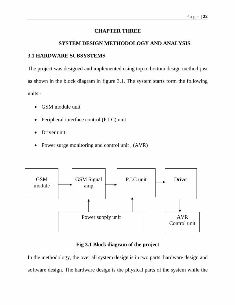
3.1 HARDWARE SUBSYSTEMS
The project was designed and implemented using top to bottom design method just
as shown in the block diagram in figure 3.1. The system starts form the following
units:-
GSM module unit
Peripheral interface control (P.I.C) unit
Driver unit.
Power surge monitoring and control unit , (AVR)
Fig 3.1 Block diagram of the project
In the methodology, the over all system design is in two parts: hardware design and
software design. The hardware design is the physical parts of the system while the
GSM
module
P.I.C unit
Driver
Power supply unit
GSM Signal
amp
AVR
Control unit
P a g e | 23
software design treats the programs that were written to control the microcontroller
at the processing center of the system. The hardware design is the heart of the
project. This is the physical implementation where the various components used
for the design were incorporated together on a vero board through soldering. It
consists of many units which includes a GSM module, a PIC unit and other units
listed above.
3.2 SYSTEM ANALYSIS AND DESIG
The system uses GSM signal system which allows its users to effectively control
their house/office appliances simply by calling the device.
The call receive by the device is processed by a microcontroller to perform an OFF
operations. The type of the operation performed is based on the nature of the GSM
signal sent. An encoded GSM signal is generated and sent from the GSM base
station to the device.
In this project two GSM module are involved:
The GSM transmitter module which is the users cell phone
The GSM receiver module which is the cell phone connected to the
project.
There are lots of remote controls methodology like infrared, RF, SMS and more
but in this project I prefer the calling system using GSM network. SMS control
P a g e | 24
system uses the GSM network as well but the problem with it is that SMS
sometimes does not arrive on time. In the design methodology, GSM network was
used because of its wider coverage.
The relay driver is used to drive the relay circuits which switches the different
appliances connected to the output of the project.
The figure shown above is the schematic diagram of our project. It is a simple
illustration of how we have implemented our project and the various parts involved
in it. From the above representation, the first Mobile station is used as a
transmitting section from which the subscriber makes a call which is the command
or instruction for the second mobile station. A SIM card is inserted in the receiver
cell phone.
P a g e | 25
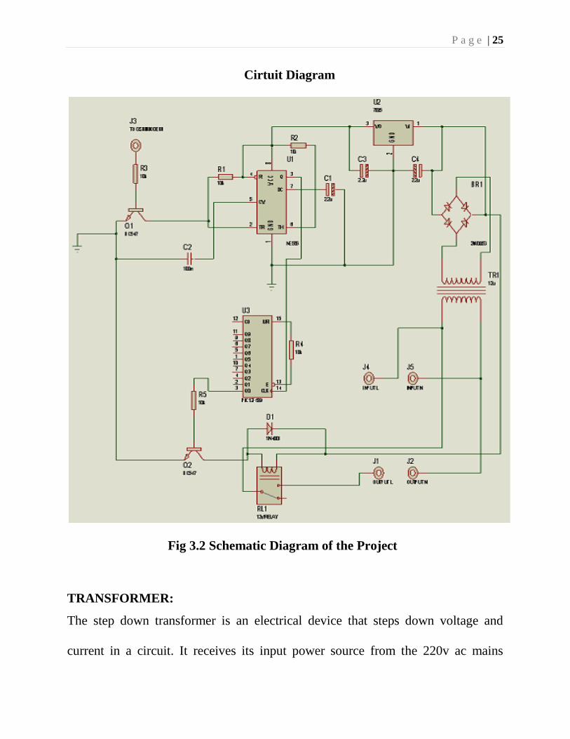
Cirtuit Diagram
Fig 3.2 Schematic Diagram of the Project
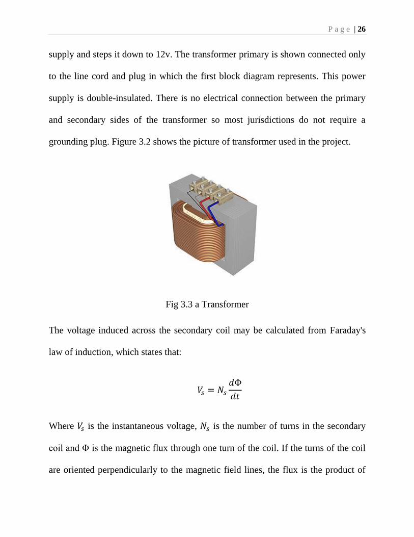
TRANSFORMER:
The step down transformer is an electrical device that steps down voltage and
current in a circuit. It receives its input power source from the 220v ac mains
P a g e | 26
supply and steps it down to 12v. The transformer primary is shown connected only
to the line cord and plug in which the first block diagram represents. This power
supply is double-insulated. There is no electrical connection between the primary
and secondary sides of the transformer so most jurisdictions do not require a
grounding plug. Figure 3.2 shows the picture of transformer used in the project.
Fig 3.3 a Transformer
The voltage induced across the secondary coil may be calculated from Faraday's
law of induction, which states that:
𝑉𝑠 = 𝑁𝑠
𝑑Φ
𝑑𝑡
Where 𝑉𝑠 is the instantaneous voltage, 𝑁𝑠 is the number of turns in the secondary
coil and Φ is the magnetic flux through one turn of the coil. If the turns of the coil
are oriented perpendicularly to the magnetic field lines, the flux is the product of
P a g e | 27
the magnetic flux density B and the area A, through which it cuts. The area is
constant, being equal to the cross-sectional area of the transformer core, whereas
the magnetic field varies with time according to the excitation of the primary.
Since the same magnetic flux passes through both the primary and secondary coils
in an ideal transformer, the instantaneous voltage across the primary winding
equals
𝑉𝑝 = 𝑁𝑝
𝑑Φ
𝑑𝑡
Taking the ratio of the two equations for 𝑉𝑠 and 𝑉𝑝 gives the basic equation for
stepping up or stepping down the voltage
𝑉𝑠
𝑉𝑝=
𝑁𝑠
𝑁𝑝
𝑁𝑝 ∕ 𝑁𝑠 is known as the turn ratio, and is the primary functional characteristic of
any transformer. In the case of step-up transformers, this may sometimes be stated
as the reciprocal, 𝑁𝑝 ∕ 𝑁𝑠. Turns ratio is commonly expressed as an irreducible
fraction or ratio: for example, a transformer with primary and secondary windings
of, respectively, 100 and 150 turns is said to have a turns ratio of 2:3 rather than
0.667 or 100:150.
P a g e | 28
3.3 REGULATION UNIT
Regulation is a measure of the difference in voltage provided by the transformer's
secondary winding when it is on load and off load. It is expressed as a percentage
relative to the full load voltage and, basically, the lower the value, the less the
voltage difference. Strictly speaking, the transformer's datasheet (or supplier)
should state the output voltage when the transformer is under its full rated load.
For example, a transformer rated at 12v, 50VA should provide 12v to a load which
takes 4 amps.
50𝑉𝐴 𝑎𝑡 12𝑣𝑜𝑙𝑡𝑠 = 5012⁄ = 4.1 𝐴𝑚𝑝𝑠
Our transformer provides 12.5 volts off load so, unless the regulation is
exceptionally good, the "nominal" 12 volts hasn't been specified as the on-load
voltage at all.
% 𝑟𝑒𝑔𝑢𝑙𝑎𝑡𝑖𝑜𝑛 =𝑜𝑓𝑓 𝑙𝑜𝑎𝑑 𝑣𝑜𝑙𝑡𝑎𝑔𝑒 − 𝑜𝑛 𝑙𝑜𝑎𝑑 𝑣𝑜𝑙𝑡𝑎𝑔𝑒
𝑜𝑛 𝑙𝑜𝑎𝑑 𝑣𝑜𝑙𝑡𝑎𝑔𝑒× 100
=12.5 − 12
12× 100
= 4%
Later tests proved that the output voltage dropped to less than 11.4 volts when
presented with a load of just 2 Amps. At best, this is a regulation of around 14%
P a g e | 29
even at just 2 Amps. The disadvantage of using a transformer with too high an
output voltage is that the regulator will need to work harder and dissipate even
more surplus energy and, as the maximum off load voltage will be higher, the
voltage monitoring circuit will need to take the higher voltage into account.
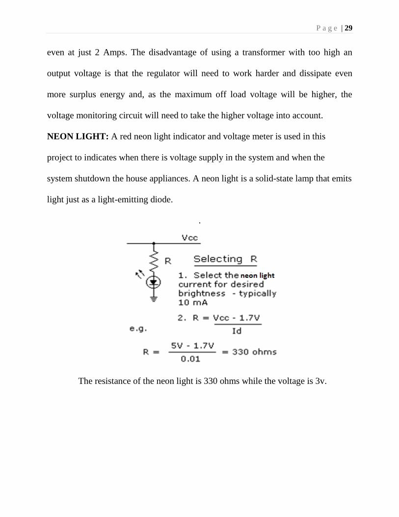
NEON LIGHT: A red neon light indicator and voltage meter is used in this
project to indicates when there is voltage supply in the system and when the
system shutdown the house appliances. A neon light is a solid-state lamp that emits
light just as a light-emitting diode.
.
The resistance of the neon light is 330 ohms while the voltage is 3v.
P a g e | 30
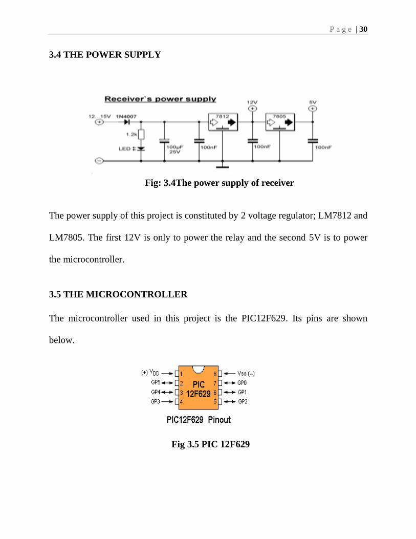
3.4 THE POWER SUPPLY
Fig: 3.4The power supply of receiver
The power supply of this project is constituted by 2 voltage regulator; LM7812 and
LM7805. The first 12V is only to power the relay and the second 5V is to power
the microcontroller.
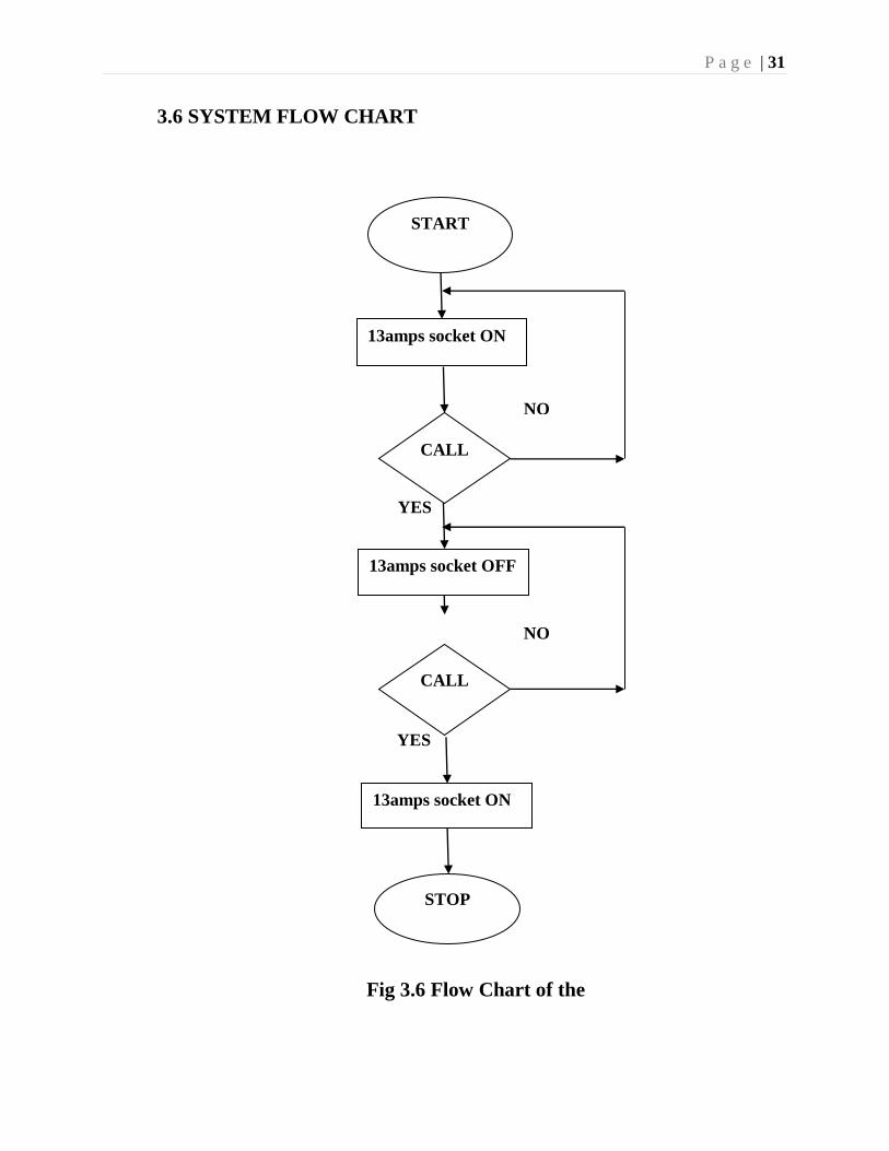
3.5 THE MICROCONTROLLER
The microcontroller used in this project is the PIC12F629. Its pins are shown
below.
Fig 3.5 PIC 12F629
P a g e | 31
YES
YES
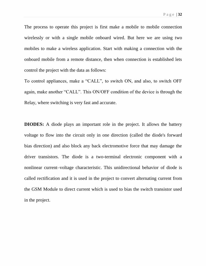
3.6 SYSTEM FLOW CHART
Fig 3.6 Flow Chart of the
NO
NO
START
13amps socket ON
CALL
13amps socket OFF
CALL
13amps socket ON
STOP
P a g e | 32
The process to operate this project is first make a mobile to mobile connection
wirelessly or with a single mobile onboard wired. But here we are using two
mobiles to make a wireless application. Start with making a connection with the
onboard mobile from a remote distance, then when connection is established lets
control the project with the data as follows:
To control appliances, make a “CALL”, to switch ON, and also, to switch OFF
again, make another “CALL”. This ON/OFF condition of the device is through the
Relay, where switching is very fast and accurate.
DIODES: A diode plays an important role in the project. It allows the battery
voltage to flow into the circuit only in one direction (called the diode's forward
bias direction) and also block any back electromotive force that may damage the
driver transistors. The diode is a two-terminal electronic component with a
nonlinear current–voltage characteristic. This unidirectional behavior of diode is
called rectification and it is used in the project to convert alternating current from
the GSM Module to direct current which is used to bias the switch transistor used
in the project.
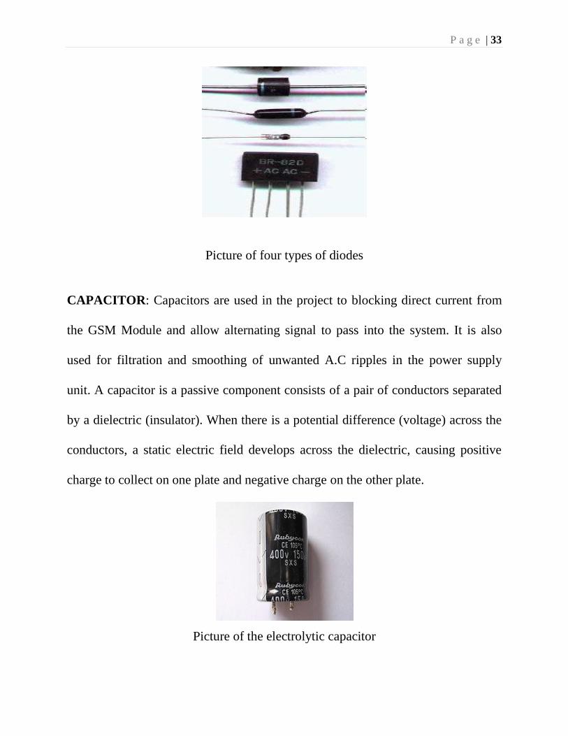
P a g e | 33
Picture of four types of diodes
CAPACITOR: Capacitors are used in the project to blocking direct current from
the GSM Module and allow alternating signal to pass into the system. It is also
used for filtration and smoothing of unwanted A.C ripples in the power supply
unit. A capacitor is a passive component consists of a pair of conductors separated
by a dielectric (insulator). When there is a potential difference (voltage) across the
conductors, a static electric field develops across the dielectric, causing positive
charge to collect on one plate and negative charge on the other plate.
Picture of the electrolytic capacitor
P a g e | 34
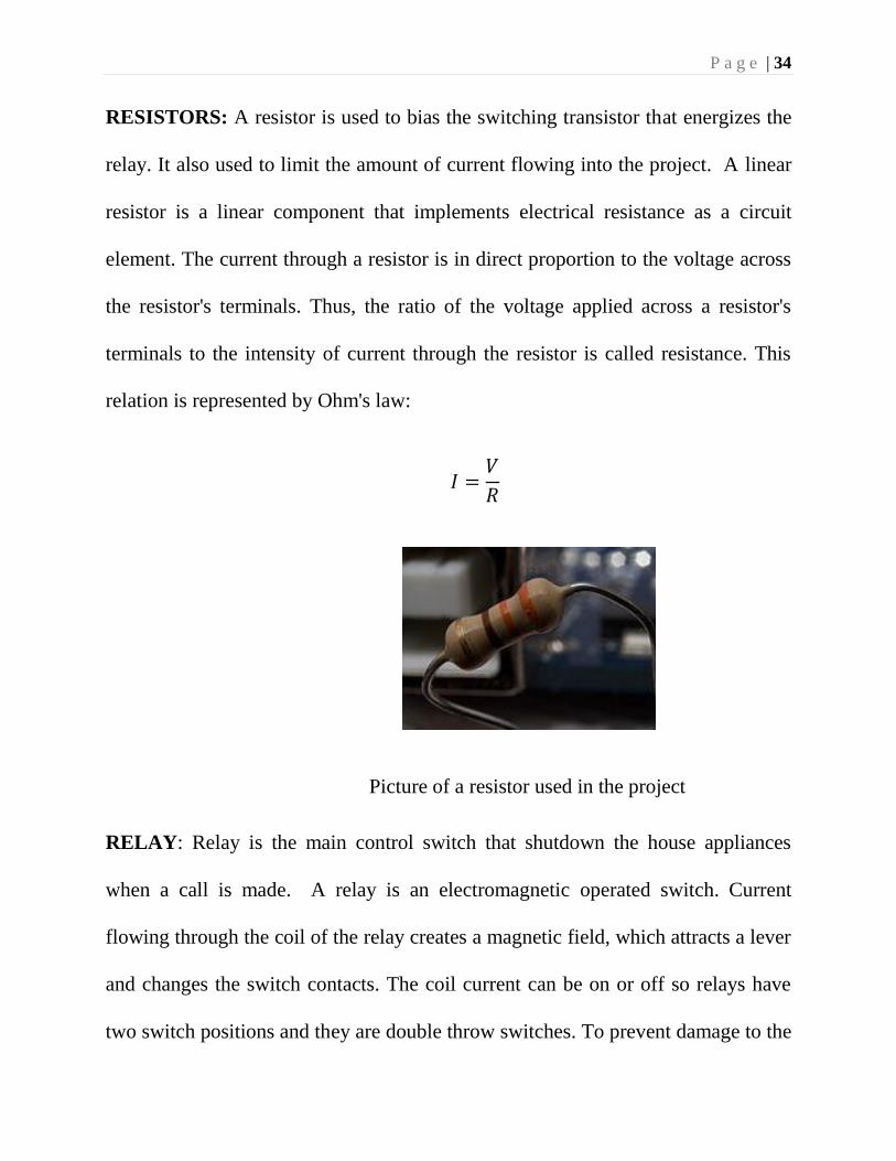
RESISTORS: A resistor is used to bias the switching transistor that energizes the
relay. It also used to limit the amount of current flowing into the project. A linear
resistor is a linear component that implements electrical resistance as a circuit
element. The current through a resistor is in direct proportion to the voltage across
the resistor's terminals. Thus, the ratio of the voltage applied across a resistor's
terminals to the intensity of current through the resistor is called resistance. This
relation is represented by Ohm's law:
𝐼 =𝑉
𝑅
Picture of a resistor used in the project
RELAY: Relay is the main control switch that shutdown the house appliances
when a call is made. A relay is an electromagnetic operated switch. Current
flowing through the coil of the relay creates a magnetic field, which attracts a lever
and changes the switch contacts. The coil current can be on or off so relays have
two switch positions and they are double throw switches. To prevent damage to the
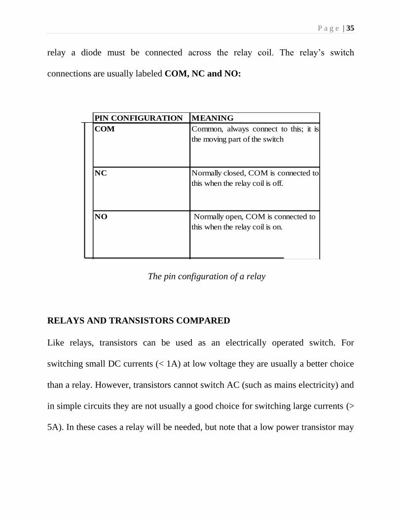
P a g e | 35
relay a diode must be connected across the relay coil. The relay’s switch
connections are usually labeled COM, NC and NO:
PIN CONFIGURATION MEANING
COM Common, always connect to this; it is
the moving part of the switch
NC Normally closed, COM is connected to
this when the relay coil is off.
NO Normally open, COM is connected to
this when the relay coil is on.
The pin configuration of a relay
RELAYS AND TRANSISTORS COMPARED
Like relays, transistors can be used as an electrically operated switch. For
switching small DC currents (< 1A) at low voltage they are usually a better choice
than a relay. However, transistors cannot switch AC (such as mains electricity) and
in simple circuits they are not usually a good choice for switching large currents (>
5A). In these cases a relay will be needed, but note that a low power transistor may

P a g e | 36
still be needed to switch the current for the relay's coil! The main advantages and
disadvantages of relays are listed below:
ADVANTGES OF RELAYS:
Relays can switch AC and DC, transistors can only switch DC.
Relays can switch higher voltages than standard transistors.
Relays are often a better choice for switching large currents (>5A).
Relays can switch many contacts at once.
DISADVANTAGES OF RELAYS:
Relays are bulkier than transistors for switching small currents.
Relays cannot switch rapidly (except reed relays), transistors can switch
many times per second.
Relays use more power due to the current flowing through their coil.
Relays require more current than many ICs can provide, so a low power transistor
may be needed to switch the current for the relay's coil.
P a g e | 37
CHAPTER FOUR
SYSTEM IMPLEMENTATION AND PROJECT COSTING
CONSTRUCTION AND COMPONENTS LIST
4.1 CONSTRUCTION
The term stage is associated to a group of components, which is aimed at
achieving a specific purpose. This has been broken down in the previous
chapter. Each of the stage will now be treated more elaborately.
4.2 CONSTRUCTIONAL METHOD
The construction of this project was done on a vero board. Vero board is
called strip board. It is a widely-used type of electronics prototyping board
characterized by a 0.1 inch (2.54 mm) regular (rectangular) grid of holes, with
wide parallel strips of copper cladding running in one direction all the way
across one side of the board. In using the board, breaks are made in the tracks,
usually around holes, to divide the strips into multiple electrical nodes. With
care, it is possible to break between holes to allow for components that have
two pin rows only one position apart such as twin row headers for ICs.
P a g e | 38
4.3 POWER SUPPLY UNIT (PSU)
The transformer is connected to mains of 220v/50Hz through a power cord of
R ohm resistance. The transformer’s (12v/500mA) secondary output is
connected to the bridge rectifier source inputs. An output is taken from the
negative and positive terminals of the rectifier and connected to the
corresponding pins in the 1000uF/35v capacitor. This bridge rectifier the
supply while the capacitor filters the A.C voltage lefts and equally smoothens
the signal into a pure D.C voltage of 12vDC. The positive terminal of the
capacitor is connected to pin 1 of the 7805 voltage regulator, while the
negative terminal connects to pin 2 of the regulator. This regulator produces
an output of +5v between pin 3 and pin 2(Ground).
Vero board: The construction of this project was done on a vero board and the
procedure methods used are: -
1. The vero board was inspected of wrong linkages of its line which may
be mistake from the producers. The holes of the board were made sure
to be through for passing the terminals of the components for soldering.
2. An abrasive paper was used on the soldering section of the board for
easy binding of the terminals on the board.
P a g e | 39
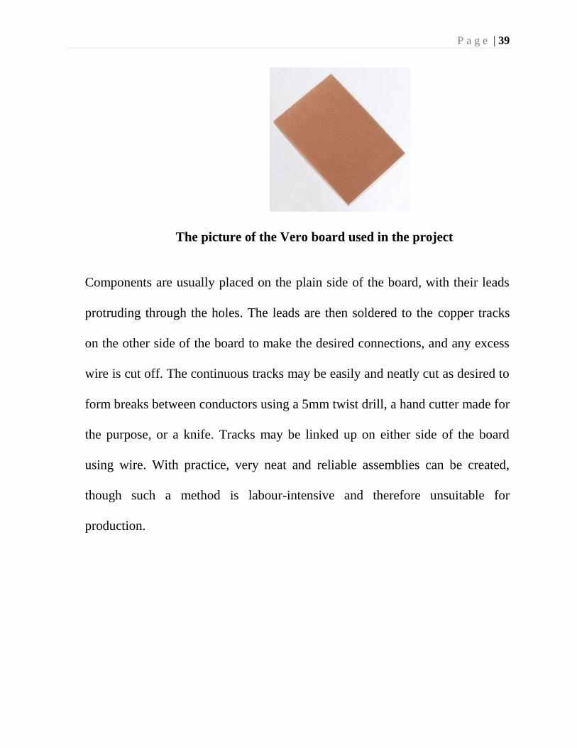
The picture of the Vero board used in the project
Components are usually placed on the plain side of the board, with their leads
protruding through the holes. The leads are then soldered to the copper tracks
on the other side of the board to make the desired connections, and any excess
wire is cut off. The continuous tracks may be easily and neatly cut as desired to
form breaks between conductors using a 5mm twist drill, a hand cutter made for
the purpose, or a knife. Tracks may be linked up on either side of the board
using wire. With practice, very neat and reliable assemblies can be created,
though such a method is labour-intensive and therefore unsuitable for
production.
P a g e | 40
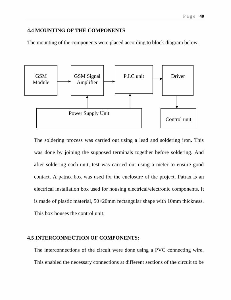
4.4 MOUNTING OF THE COMPONENTS
The mounting of the components were placed according to block diagram below.
The soldering process was carried out using a lead and soldering iron. This
was done by joining the supposed terminals together before soldering. And
after soldering each unit, test was carried out using a meter to ensure good
contact. A patrax box was used for the enclosure of the project. Patrax is an
electrical installation box used for housing electrical/electronic components. It
is made of plastic material, 50×20mm rectangular shape with 10mm thickness.
This box houses the control unit.
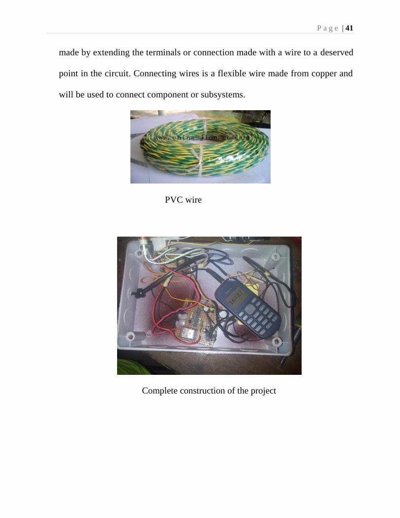
4.5 INTERCONNECTION OF COMPONENTS:
The interconnections of the circuit were done using a PVC connecting wire.
This enabled the necessary connections at different sections of the circuit to be
GSM
Module
P.I.C unit
Driver
Power Supply Unit
GSM Signal
Amplifier
Control unit
P a g e | 41
made by extending the terminals or connection made with a wire to a deserved
point in the circuit. Connecting wires is a flexible wire made from copper and
will be used to connect component or subsystems.
PVC wire
Complete construction of the project
P a g e | 42
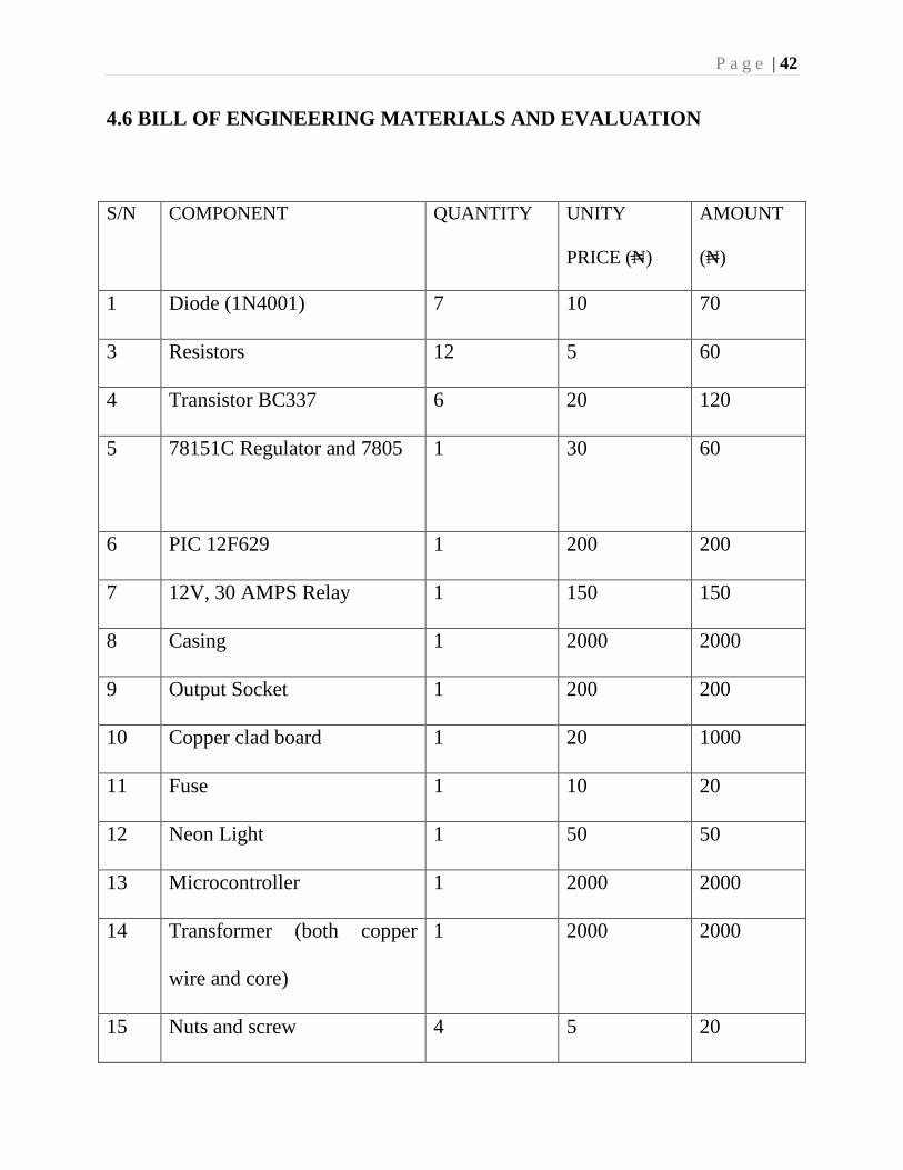
4.6 BILL OF ENGINEERING MATERIALS AND EVALUATION
S/N COMPONENT QUANTITY UNITY
PRICE (N)
AMOUNT
(N)
1 Diode (1N4001) 7 10 70
3 Resistors 12 5 60
4 Transistor BC337 6 20 120
5 78151C Regulator and 7805 1
30
60
6 PIC 12F629 1 200 200
7 12V, 30 AMPS Relay 1 150 150
8 Casing 1 2000 2000
9 Output Socket 1 200 200
10 Copper clad board 1 20 1000
11 Fuse 1 10 20
12 Neon Light 1 50 50
13 Microcontroller 1 2000 2000
14 Transformer (both copper
wire and core)
1 2000 2000
15 Nuts and screw 4 5 20
P a g e | 43
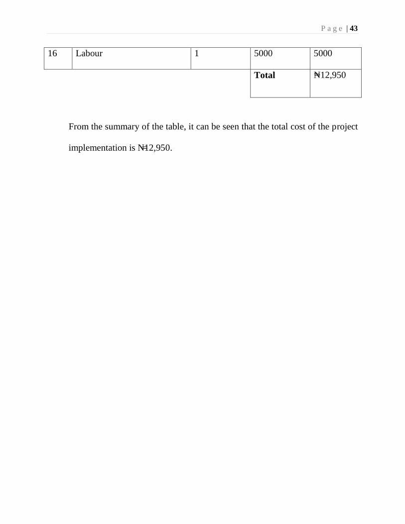
16 Labour 1 5000 5000
Total N12,950
From the summary of the table, it can be seen that the total cost of the project
implementation is N12,950.
P a g e | 44
CHAPTER FIVE
RECOMMENDATION, CONCLUSION AND CONSTRAINTS
5.1 CONCLUSION
The GSM based home automation using AVR was designed and constructed
to CONTROL 230V+5% ac load. It is rated 2500VA 50Hz.
This project has really exposed me to the use of electronic component. To a
large extent I have come to appreciate the theories learned over the years.
5.2 RECOMMENDATION
It is a fact that this is not exhaustive. It can still be improved to get a more
sensitive and precise output voltage control.
For this reason I recommend the following.
1. Two layers circuit board can be designed and used in place of single
layer circuit board for easier soldiering work and neatness.
2. Further research in the field of electronics switching will go a long way
in getting better house control system.
3. Engineering students need early exposure to the use of electronic
components for practical work; this will enable them to be more
innovative.
P a g e | 45
5.3 MAJOR CONSTRAINTS
Along the course of project completion we encountered various problems
and obstacles. Not everything that we had planned went smoothly during the
project development span. Also we had a limited amount of time for its
completion so we were under a certain amount of pressure as well. We had
to start from the research phase at the beginning and needed to gain
knowledge on all the devices and components that we had intended to use
for our project. Other phases of the project included coding, debugging,
testing, documentation and implementation and it needed certain time for
completion so we really had to manage the limited time available to us and
work accordingly to finish the project within the schedule.
5.4 CONSTRAINTS CONSIDERATIONS
The following is a list of constraint considerations
The controlled appliances will need an electrical control interface. This
system is only capable of controlling electrical devices.
The control module will need to be shielded against electrostatic discharges.
This will increase the reliability of the system.
Battery backup for controlling unit can be implemented in case of power
disruption.
P a g e | 46
5.5 TECHNOLOGY CONSIDERATIONS
The considerations for this system will include a choice of networks,
communication protocols and interfaces.
Cellular Networks: The widely available networks are based on GSM. This
network provides wide area coverage and can be utilized more cost-
effectively for this project.
Communication Protocols: The available communication protocol that we
have used is phone call. The phone call is the most efficient because this
project requires a cellular communication and limited data to be sent.
I/O interfaces between microcontroller and devices: Serial I/O is considered
as options for connection between the GSM receiver and the
microcontroller. Using the microcontroller, a control circuit will be
implemented to control the electrical appliances.
P a g e | 47
REFERENCES
Alkar, A. Z., & Buhur, U. (2005). An Internet Based Wireless Home Automation System for
Multifunctional Devices. IEEE Consumer Electronics, 51(4), 1169-1174.Retrieved from
http://www.thaieei.com
Ciubotaru-Petrescu, B., Chiciudean, D., Cioarga, R., & Stanescu, D. (2006). Wireless Solutions
for Telemetry in Civil Equipment and Infrastructure Monitoring. 3rd Romanian-Hungarian
Joint Symposium on Applied Computational Intelligence (SACI) May 25-26, 2006.
Retrieved from http://www.bmf.hu
Conte, G., & Scaradozzi, D. (2003). Viewing home automat ion systems as multiple agents
systems. RoboCUP2003,
Delgado, A. R., Picking, R., & Grout, V. (2006) Remote-controlled home automation systems
with different network technologies. Proceedings of the 6th International Network
Conference (INC 2006), University of Plymouth, 11-14 July 2006, pp. 357-366. Retrieved
from http://www.newi.ac.uk
Harper, R. (2003), Inside the Smart Home, Springer-Verlag, London, UK.
Heckman, D. (2008), A Small World. Smart Houses and the Dream of the Perfect day, Duke
University Press, London, UK.
Jawarkar, N. P., Ahmed, V., Ladhake, S. A. & Thakare, R. D. (2008). Micro-controller based
Remote Monitoring using Mobile through Spoken Commands.
Journal of Networks, 3(2), 58-63. Retrieved from http://www.academypublisher.com
Murthy, M. V. R. (2008). Mobile based primary health care system for rural India. W3C
workshop on Role of Mobile Technologies in Fostering Social Development, Jun 2008.
P a g e | 48
Potamitis, I., Georgila, K., Fakotakis, N., & Kokkinakis, G. (2003). An integrated system for
smart-home control of appliances based on remote speech interaction. EUROSPEECH
2003, 8th European Conference