Embed Size (px)
Citation preview
(
I
Transportation Research Record 749
on the energy per drop but also on the sequence of drop points and the nw11ber of drops at each point. Available data from Belgium (3), Sweden (4), France (5), Scotland (6), Israel (7), and Chicago (8), as well as these, suggest that, for dry granular sOlls, the degree of compaction Cas measured by q0 ) correlates best with the product of the energy per drop and the total energy applied pel' unit of surface area (Figure 5). It appears that there may be an upper bound to the densification that can be achieved, corresponding approximately to q. = 150 kg/cm 2
, but more data are needed to verify this result.
CONCLUSIONS
1. In granular soils, the depth to which densilication is significant is controlled mainly by the energy per drop: Relationship la given above .is recommended as a guide for preliminary trials . The presence of clay layers or seams will greatly attenuate the effective depth of compaction.
2. The upper meter of soil is usually left in a relatively loose state, and surface recompaction is required.
3. For dry granular soils, the degree of compaction achieved seems to correlate best with the product of the energy per drop and the total energy applied per unit surface area. It appears that there may be an upper bound to the compaction that can be attained and that this corresponds to q.,,. 150 kg/cm 2 (N = 30-40).
REFERENCES
1. G. A. Leonards, W. A. Cutter, and R. D. Holtz.
13
Dynamic Compaction of Granular Soils. Journal of the Ckotechnkal Engineering Division, Proc., ASCE, Vol. 106, No. GTl , Jan. 1980, pp. 35-44. .
2 . L. Menard and Y. Broise. Theoretical and Practi .:· cal Aspects of Dynamic Consolidation. Gt!otechnique, Vol. 25, No. 1, 1975, pp. 3-18. .
3. E. DeBeer and A. Van Wambeke. Consolidation Dynamique par Pilonnage Intensif, Aire d'Essai d'Embourg. Annales des Travau.x Publics de Belgique, No. 5, Oct. 1973, pp. 295-318.
4. S. Hansbo, B. Pramborg, and P. 0. Nordin. The Va'.nern Terminal: An illustrative Example of Dynamic Consolidation of Hydraulically Placed Fill . Les Edition Sols-Soils, No. 25, 1973, pp. 5-11.
5. J . P. Gigan. Compactage par Pilonnage ·J.ntensif de ]lemb)ais d.e Comblement d'un Bras de Seine. Laboratoires des Pools et Chaussees, Paris, Bull. de Liaison, Vol. 90, July-Aug . 1977, pp. 81-102.
6. J. M. West and B. £. Slocombe. Dynamic Consolidation as an Alternative Foundation. Ground Engineering, Vol. 6, No. 6, 1973, pp. 52-54.
7. D. David. Deep Compaction. D. David Engineers, Ltd., :Ramat Avh•, Israel, Bull., no date.
8. R. G. Lukas. Densilication of Loose Deposits by Pounding. Journal of the Geotechnical Engineering Di\'ision, Proc., ASCE, Vol. 106, No. GT4, April 1980, pp. 435-461.
Publication of this.paper sponsored by Committee on Embankments and Earth Slopes.
Construction of a Root-Pile Wall at Monessen, Pennsylvania Umakant Dash and Pier Luigi Jovino
A e<ise history of the design, analysis, construction, and performance evaluation of a root·pile wall is presented in th is paper. The root·plle wall was contracted for construction by the Pennsylvania Department of Transportation to correct a landslide near Monessen. The structure con· sisted of four hundred and fifty-eight 12.5·cm (S.in) diameter cast·in· piece conc1ete piles placed at different inclinations to both the vertical and the horizontal axes. The piles were connected at the top by a 76.2-cm (30·in) ttlick by 1.82·m (6-ft) wide cap beam conwucted in two 30.48·m (100·ft) sections. The cap beam was constructed first, and the root pile-s were then Installed by extending drill holes through the cap beam to bedrock at predetermined locations and Inclinations, insert· ing a single no. 9 deformed reinforcing steel bar (grade 60) nto each drill hole, and grouting the holes. Nine survey targets were marked at the top of the cap l>eam to measure both horizontal and vertical movements and seven slope inclinometers were installed at various points both upslope and downslope from the structure to measure horizontal move· ments of the structure and the surrounding soil. This paper describes tile soil and groundwater conditions, soil test rtsu lts . slope stability analyses, design of the root-pile wall, and the findings of the horizontal and veni· cal measurements of wall movement . The f_ollowing summary, observa· tlons. and conclusions are made : (a) a root-pile structure provides a fast and economical alternative to many conventional structures; (b) before the installat ion of the roqt piles. the movements of the cap beam varied from less than 2.5 cm ( 1 in) at the north end to more than 45. 7 cm ( 18 in) at the sound end- these movements were due to movements of unstable soil in t~e slide area; (c) after the installation of the root piles,
there were significant movements [up to 5 cm (2 in)) in the cap beam 8$ well as in the soil below it, which indicated that some movement of the root·pile structure wa' needed before resistance to earth pressure could be mobiliud; (d) no significant $Oil movement through the root piles could be detected-the small-diameter piles and the soil between them appeared to work as a single composite structure; and (e) oonven· tional design procedures for retaining walls appear to provide adequate overall design for root·pile walls (the geometry of the root-pile structure described in this paper is patented and may not be the optimum design for all situations).
During the construction of a four-lane highway along the Monongahela Ri\•er, just north or I-70, a series of landslides occurred. One of these landslides, at the northern end of the project, involved the new highway construction, as well as two water lines and a cit~· street abo\·e the slope about 76 m (250 ft ) from the northbound lanes.
A root-pile wall was designed and constructed to correct the landslide along PA-306 in Monessen, Pennyslvania. Se\·eral alternatl\'es (such as tieback, reinforced-earth, and conc1·ete- gra\·it y walls) we1·e considered, but the root-pile method of correction was
(
(
14
Figure 1. Cross section at center of landslide area.
275m (902')
38m (125')
25m . 82'
Figure 2. Aerial photograph of site.
SOm .
164'
selected because it would require the least amount of disturbance and the minimum time and have a cost comparable with that of the other systems . Another consideration in the selection decision was that this would allow evaluation of the procedure to determine its feasibility for future corrective works .
Root piles are small-diameter reinforced-concrete piles developed by the Fondedile Corporation specifically for strengthening soil or rock that i s othe r wise incapable of s upporting its own load a nd/or an external load (1, 2). The method is efficient and economical and s uitable Tor a variety of underpinning, restoration, and stabilization work.
SITE CONDITIONS
Stratigraphically, the slide area was confined to the upper portion of the Conema ugh formation of the P ennsyl ..: vania period. These st rata vary fro m hard massive sandstone to red shale s and have minor limes tone interbeds. The overburden cont;iins s urface debFis from mining operations, as well as foundati•ms and other construction materials Crom demolished houses in the area.
A cr oss section at t he center of the landslide area, including soil t~'J)es and groundwater ele \•ations, is shown in Fi:;ure 1. The section also shows the locations of the highway at the bottom, the root-pile wall near the
Transportation Research Record 749
Water Table
Secondary Side
l
328'
middle, and the city street (Highland A venue) near the top of the failed slope.
Figure 2 is an oblique aerial photograph taken soon after the failure and shows the general site conditions, the scarps, the acid mine-drainage channel, the location of a water pipe, and the location of the root-pile wall. The over burden soils (fill and colluvium) consisted of silty clays and clayey silts (AASHO A-6 and A-7) intermixed with rock fragments, cinders, and building materials.
The groundwater elevation varied from near the surface to about 3 m (10 ft) below the surface. Extremely wet conditions prevailed for most of the year, particularly around the acid mine-drainage channel.
SLOPE STABILITY
Slope stability analyses were performed by using a generalized soil profile and groundwater near the surface. The top and bottom scarps and the rock line were used as part of the assumed failure surface (Figure 1 ). Several slope-stability-analysis trials were made by using the Morgenstern- Price method and varying the effective angle of i~ternal friction with each trial until a factor of safety nearly equal to 1.0 was obtained. The most-probable values of soil strength parameters obtained by using this method were c = 4,79 kPa (100 lbf/ ft2 ) and o = 17°. The maxi mum mass density (y) [2146 kg/m3 (134 lb/ ft3
) ] was obtained b}' llSing the Proctor compaction test.
DESIGN
The design of a root-pile structure involves (a) selection of the location; (b) selection of the size; (c) selection of the pile arrangement-including spacing, inclination, length, and size of the individual piles ; (d) checking the loads and stresses on the individual piles; and (e) checking probable movements of the structure. The method used for the pile arrangement at present (1979) is mostly derived from experience and is patented by the Fondedile Corporation (3, 4 ). The effective soil paramete r s used in the design-ofthe root-pile wall were those cited above.
The resllltant earth pressure (p ) can be calculated by using Equation 1 and Figure 3.
( l l
(
Transportation Research Record 749
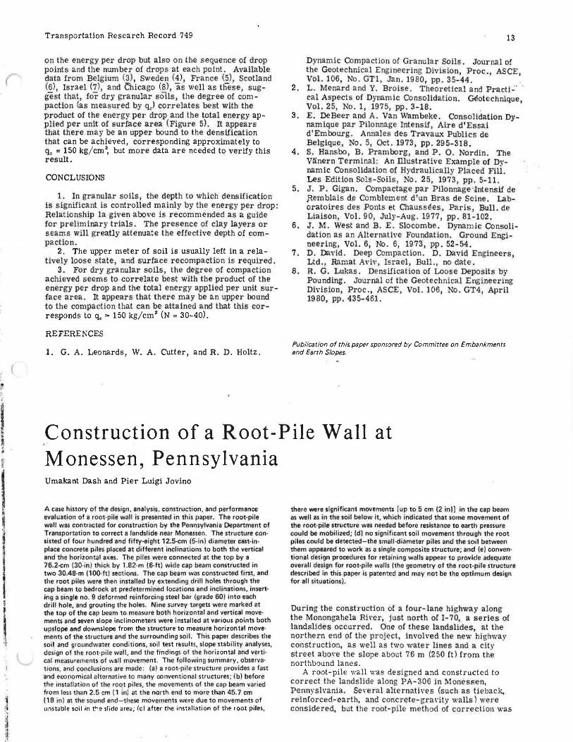
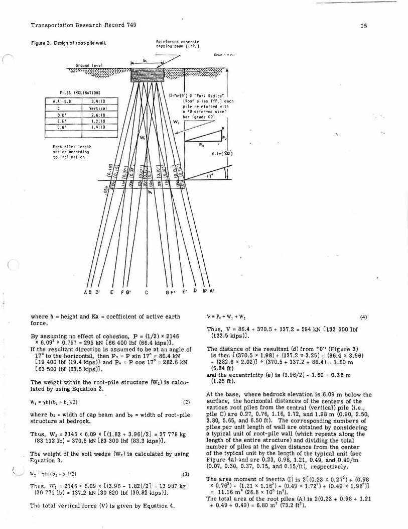
Figure 3. Design of root-pile wall. Reinforced concrete capping beam ( TYP. )
15
Settle 1 "' 60
PILES IHCLIHATIOHS
1# ' 1 12-7on(5") ~"Pali Radice"
(Roof p i1 es TYP.) each pile reinforced with
A. A': B. B' 3 . ij: 10
c Vertical a '9 deformed steel
0,0' 2. 6: 10 bar (grade 60}.
~ E. E' 1.3: I 0 G, G' I ,ij: 10
Each pi Jes length varies according to inclination.
AB 0' E F G' c G F' E' 0 s· A'
where h =height and Ka = coefficient of active earth force.
By asswning no effect of cohesion, P = (1/2) >< 2146 >< 6.092 x 0.757 = 295 kN ( 66 400 lbC (66.4 kips)).
If the resultant direction is assumed to be at an angle of 17° to the horizontal, then p. = P sin 17° = 86.4 kN [ 19 400 lb! (19.4 kips )) and p ,. = P cos 17° = 282.6 kN (63 500lbf (63.5kips)).
The weight within the root-pile structure (W1) is calculated by using Equation 2.
w. = -yh[fb1 + b,)/2] (2)
where bi = width of cap beam and In = width of root-pile structure at bedrock.
Thus, W1 = 2146 )( 6.09 )( [(1.82 + 3.96)/2) = 37 778 kg (83 112 lb) = 370.5 kN [83 300 lbf (83.3 kips)].
The weight or the soil wedge (W2) is calculated by using Equation 3.
(3)
Thus, W2 = 2146 x 6.09 x [(3.96 - 1.82)/2] = 13 987 kg (30 771lb)=137.2 kN [30 820 lbf (30.82 kips)].
The total \"ertical force (V) is given by Equation 4.
Thus, V = 86.4 + 370.5 + 137.2 = 594 kN [133 500 lbf (133.5 kips)].
(4)
The distance of the resultant (d) from "0" (Figure 3) is then [ (370.5 x 1.98) + (137.2 x 3.25) + (86.4 x 3.96) - (282.6 x 2.02)] + (370.5 + 137.2 + 86.4) = 1.60 m (5.24 ft)
and the eccentricity (e) is (3.96/2) - 1.60 = 0.38 m (1.25 ft).
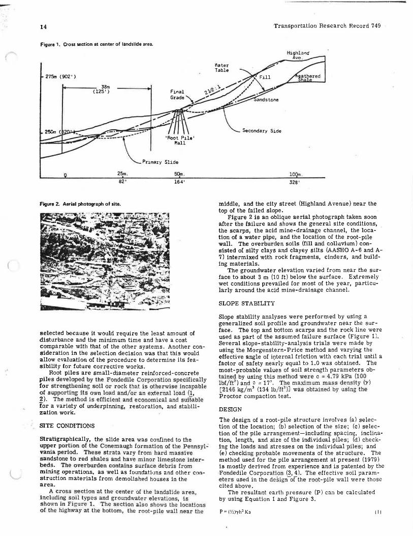
At the base, where bedrock elevation is 6.09 m below the surface, the horizontal distances of the centers of the various root piles from the central (verUcal) pile (i.e., pile C) are 0.27, 0.76, 1.16, 1.72, and 1.98 m (0.90, 2.50, 3.80, 5.65, and 6.50 ft). The corresponding numbers of piles per unit length of wall are obtained by considering a typical unit o! root-pile wall (which repeats along the length o[ the entire structure) and dividing the total number of piles at the given distance Crom the center of the typical unit by the length of the typical unit (see Figure 4a ) and are 0.23, 0.98, 1.21, 0.49, and 0.49 / m (0.07, 0.30, 0.37, 0.15, and 0.15/ ft ), respectivel~r .
The area moment of inertia (I) is 2[ (0.23 x 0.27i) + (0.98 x 0.762)+ (1.21 )( 1.161
) .. (0.49 x 1.721 )+ (0.49)(1.98l)] = 11.16 m• (26.8 x 10⁶ in•}.
The total area of the root piles (A) is 2(0.23 + 0.98 + 1.21 + 0.49 + 0.49 ) = 6.80 m2 (73.2 rt' ).
-..
(
...
16 Transportation Research Record 749
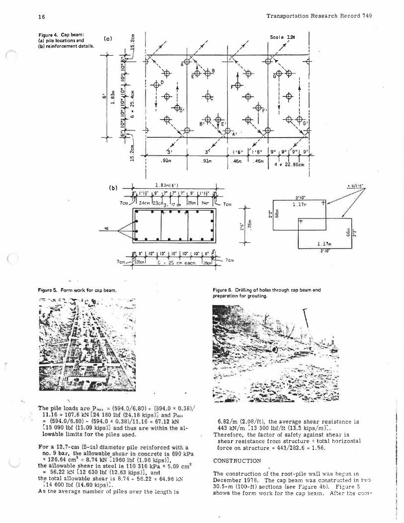
Figure 4. Cap beam: (o)
E
I u
(al pile locations and ~ I' I'
(bl reinforcement details. "' 7" / tJ I /
I /
l<.
Sec le U!4 ,. / I
I I
f\\jl-r ~~ 0
"'~,
~~,I '
,i+ :+o I
0 I t
~ E
I i + i iD u al "": ..... 0 "' N
: I -%, : ~
"' i ~ • 0 ' ' io ~
~ /
/ 0 '3 • N .,; ..... . 9lm
Figure 5. Form work for cap beam.
'·
The pile loads are P m,. = (594 .0/ 6.80) (594. 0 ic 0.38)/ 11.16"' 107.6 kN ( 24 180 lbf (24.18 kips )i and Pmiu = (594.0/ 6.80 ) - (594.0 )( 0.38 )/ 11.16 = 67.12 kN C15 090 lbf (15.09 kips )j and thus are within the allowable limits for the piles used.
For a 12._7-cm (5-in) diameter pile reinforced with a no. 9 bar, the allowable shear in concrete i s 690 kPa ic 126.64 cmi = 8.74 kN : 1960 lbf (1.96 kips)),
the allowable shear in stee l is 110 316 kPa x 5.09 cm2
= 56.22 kN ( 12 630 lbf {12.63 kips)], and the total allowable shear is 8.74 + 56.22 = 64.96 kl'< ~14 600 lbf (1 4.60 kips ):.
As the average m1mber of piles over the length is
I I I
~ + tF• !+ l i ,.
f I
I I : +1 ~-~ ' '
,. / )I jt' I
3{
.9lm
I ' 6" /I '6" 9" 9'' / 911 !) "
. 46m . 46m 4 i 22 .86cm
3•10·
l . 17m E
<D ":
I+
1
7cm
Figure 6. Drilling of holes through cap beam and preparation for grouting.
- '"· ... ~ .......... :.. ..... .... _ . ""~ &.;.. :....-~ ...
t
'° '° 17m
3'10
6.82/m (2.08/ ft ), the average shear resistance is 443 kN/ m C13 500 lbf / ft (13.5 kips/ ml:.
Therefore, the factor of safety against shear is shear resistance from structure + total horizontal force on structure = 443/282.6 = 1.56.
CONSTRUCTION
The construction of the root-pile wall was beg~n rn December 1978. The cap beam was constructed in two 30.5-m (100-ft) sections (see Figure 4b). Figure 5 shows the form work for the cap beam. After the co:n-
I,
I·
(
Transportation Research Record 749
pletion or the cap beam, construction was suspended during January and February 1979. There were movements or up to 46 cm (18 ln) in the cap beam during this period. The holes for the vertica l piles along the center line of the cap beam were dr illed firs t, and then
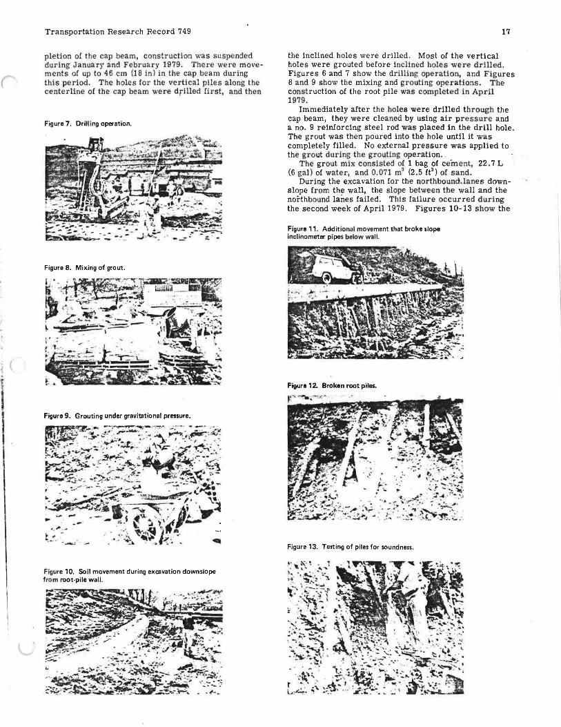
Figure 7. Drilling operation.
Figure 8. Mixing of grout .
Figure 10. Soil movement during excavat ion downslope from root-pile wall.
17
the inclined holes were drilled. Most of the vertical holes were grouted before inclined holes were drilled. Figures 6 and 7 show the drilling operation, and Figures 8 and 9 show the mixing and grouti ng operations . The const ruction of the root pile was completed in Apr il 1979.
Immediately after the holes were drilled through the cap beam, they were cleaned by using air pressure and a no. 9 reinforcing steel rod was placed in the drill hole. The grout was then poured into t he hole until it was completely filled. No external pressure was applied to the grout during the grouting operation.
The grout mix consisted of 1 bag of cement, 22. 7 L (6 gal) of water, and 0. 071 m3 (2.5 ft3) of s a nd.
During the excavation for the northbound.la nes downslope Crom the wall, the slope between the wall and the northbound lanes failed . This failure occurred d uring the second week of April 1979. Figures 10-13 show the
Figure 11 . Additional mo~e ment that broke slope inclinometer pipes below wal l.
Figure 12. Broken root piles.
Figure 13. Testing of piles for soundness.
(
18
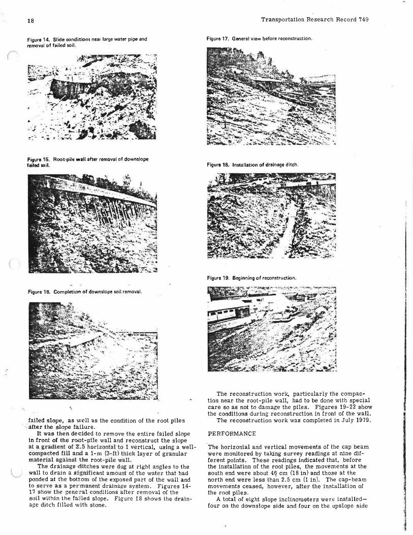
Figure 14. Slide conditions near large water pipe and removal of failed soil.
Figure 15. Root-pile wall after removal of downslope failed soil.
Figure 16. Completic:m of downslope soil removal.
"\
failed slope, as well as the condition of the root piles · -: after the slope failure.
It was then deicided to remove the entire failed slope in front of the root-pile wall and reconstruct the slope at a gradie nt of Z. 5 horizontal to 1 ve rtical, us ing a wellcompacted fi ll a md a 1-m (3- ft) thick layer of granular material against t he root - pile wall.
The drainage ditc hes were dug at right angles to the wall to drain a s f;gnHi cant amount of the wate r that had ponded at the bottom of the exposed part of the wall and to serve as a permanent draina!1:e syslem. Figures 14-17 s how the general cond itions after removal of the soil within the fa'iled slope. Figure 18 shows the draina~e ditch filled \with stone.
Transportation Research Record 749
Figure 17. General view before reconstruction .
Figure 18. Installation of drainage ditch.
Figure 19. Beginning of reconstruction.
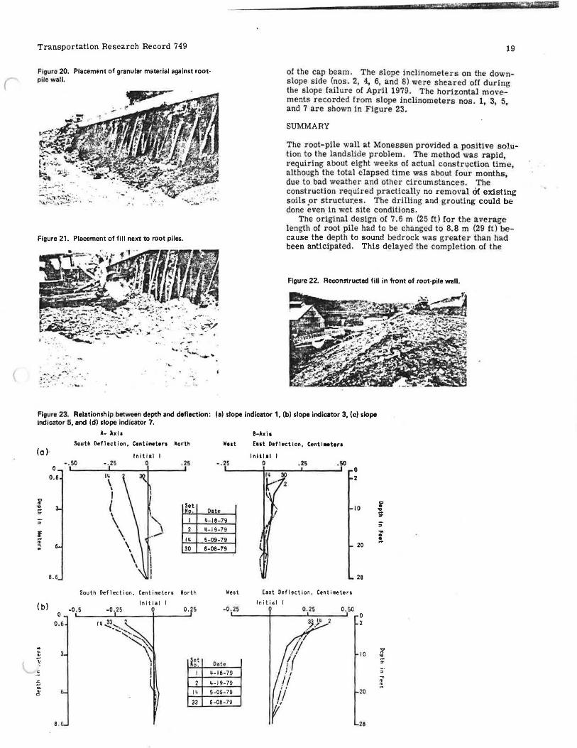
The reconstruction work, particularly the compaction near the root-pile wall, had to be done with special care so as not to damage the piles. Figures 19-22 show the conditions during reconstruction in front of the wall.
The reconstruction work was completed in July 1979.
PERFORMANCE
The horizontal and vertical movements of the cap beam were monitored by taking survey readings at nine different points. These readings indicated that, before the installation of the root piles, the movements at the south end were about 46 cm (18 in) and those at the north end were less tha'n 2.5 cm (1 in ). The cap-beam movements ceased, however, after the installation of the root piles.
A total of eight slope inclinometers were installedfour on the downslope side and four on the upslope side
l
Transportation Research Record 749
Figure 20. Placement of granular material against root· pile wall.
Figure 21. Placement of fill next to root piles.
··.
-·~ :::"' ..:: .. • f' • • •
: ... ... . ...... .
' . )It ./! - ...
19
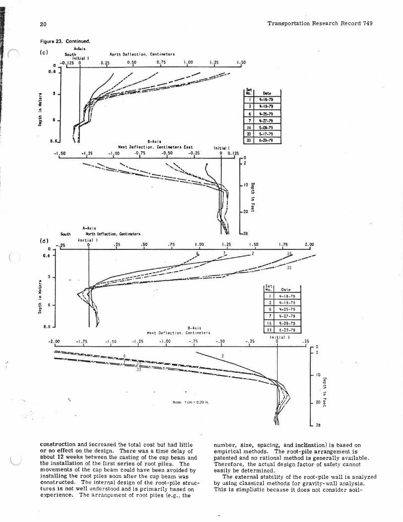
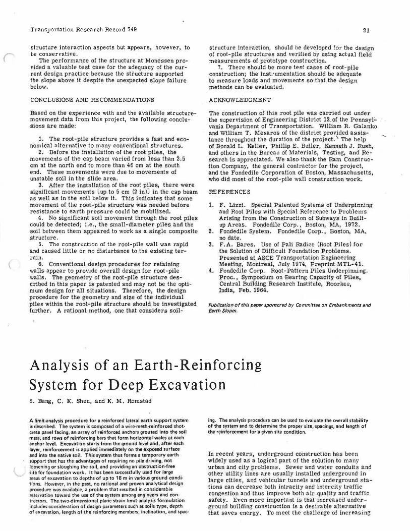
of the cap beam. The slope inclinometers on the downslope side (nos. 2, 4, 6, and 8) were sheared off durl~ the slope failure of April 1979. The horizontal mo\'ements recorded Crom slope inclinometers nos. 1, 3, 5, and 7 are shown in Figure 23.
SUMMARY
The root-pile wall at Monessen pro\lided a positive solution to the landslide problem. The method was rapid, requiring about eight weeks of actual constr1,1ction time, although the total elapsed time was about four months, due to bad weather and othe r circwnstances. The construction required practically no remo\•al Of existing soils _or structur.es . The drilling and grout1ng could be done even in wet site conditions.
The original design or 7.6 m (25 ft) for the average length of root pile had to be changed to 8.8 m (29 ft) because the depth to sound bedrock was greater than had been anticipated. This delayed the completion of the
Figure 22. Reconstructed fill in front of root-pile wall.
Figure 23. Relationship between depth and deflection: (al slope indicator 1, (bl slope indicator 3, (cl slope indicator 5, and (dl slope indicator 7.
(o )·
f ... ... :r
f ... .. ... ..
( b)
:5 .. .. C>
0 0.6
8.6
0
0.6
e.
A- lxl 1
South Deflection, Centimeter• North
Initial
w .. t
-.so -.25
·~ \ \
I { \
\ \ \
\
\ \
0 . 2S -.25
Set " • D• e
I ij-18-79 2 ij.Jg.79
IU S-09-79
30 6-08-79
South Deflection. Centimetero North Wut
-0 . S -0 . 2S Initial I
0 0.25 -0 . 25
ij-18-79
ij.19-79
I ij 5-09-79
33 6-08-79
B-Axi1
EHt Deflection, tenti•bra
Initial 0
/
.25 .50
East Deflection. Centimeters
In it i •I I 0 . 25 o.so
2
.. 1 II
' I
(( , , !I //
0 2
10
20
28
0 2
10
20
28
CJ • ... .. :r
"' i' ..
" .,., " " -
20
Figure 23. Continued.
(c)
~ • i c:
A-Axis South
Initial I 0 -0 . 125 0
0.6
3
6
. 8.6 \I
North Deflection , Centimeters
D. o. 0 o. 75 1. 00
B-Axia West Deflection , Centirneter1 Eaat
-1 . 50 -1 . 25 - 1. 00 -0 . 75 -.0. 50 -0 . 25
(d) 0
o.s
South
- . 5
A-Axi 1
North Deflection, Centift'llters
Initial I 0 . 25 .so . 75 1.00
I. 25 I . SO
Init ial I 0 0. 125
I. 25
No.
0 2
I
2
6
7
lij
20. 33
10 ii' "O ... ::r
i' 20 ...
.28
1.50
2
Transportation Research Record 749
Drle 11-16-79
~19-79
ll-2S-79
11-27-79
!MB-79 5-17-79 6-29-79
i . 75 2.00
~> .. _ ...... - --- -_::::::::...-•.• - 33 __.,,,..:::=- ... ... -=--.;;.::::::::..·:;.-,,
_____ _....
~ 6 ... .. 0
8.6
-2 . 00 .1 _75
'\
. 1. 50 -1 . 25
B-Ax i s ~e <t De f lect ion. Centimeter s
-1 .00 • . 75
Nott: 1 cm ... 0.39 in,
construction and increased the total cost but had little or no effect on the des ign. The·re wa s a time delay of about 12 weeks between the casting of the cap beam and the ins tallation or the first series or root piles . The movements of the cap beam could have been a voided by installlng the root piles soon after the cap beam was constructed. The internal design of the root-pile structures is not well unde rstood and is primarily based on e"'-perience. The arrangement of root piles (e.g., the
Set No. Date
I ij-18-79
2 ij -1 9-79
6 ij-25-79
7 ~-27-79
15 5-09-79
33 6-29 -79
I n iti al I •. so -. 25 0 . 25 0
10 0 .. "O ... ::r
" .., 20 ~ ...
28
"
number, size, spacing, and inclination) is based on empirical methods . The root-pile arrangement is patented and no rational method is generally available. Therefore, the actqal design factor of safety cannot easily be determined.
The external stability of the root-pile wall is analyzed by using classical methods for gravity-wall analysis. This is simplistic because it does not consider soil-
Transportation Research Record 749
structure interaction aspects but appears, however, to be conse n 1ati ve.
The performance of the structure at Monessen provided a valuable test case for the adequaC}' o[ the current design practice because the structure supported the slope above it despite the unexpected slope !allure below.
CONCLUSIONS AND RECOMMENDATIONS
Based on the experience with and the available structuremovement data from this project, the following conclusions are made:
1. The root-pile structure pro\•ides a fast and economical alternative to many conventional structures.
2. Before the installation or the root piles, the movements or the cap beam \•aried from less than 2.5 cm at the north end to more than 46 cm at the south end. These movements were due to movements of unstable soil in the slide area.
3. After the installation or the root piles, there were signiCicant movements Lup to 5 cm (2 in)) in the cap beam as well as in the soil below it. This indicates that some movement of the root-pile structure was needed before resistance to earth pressure could be mobilized.
4. o significant soil movement through the root piles could be detected ; Le., the small-diameter piles and the soil between them appeared to work as a single composite structure.
5. The construction of the root-pile wall was rapid and caused little or no disturbance to the existing terrain.
6. Conventional design procedures for retaining walls appear to provide overall design for root-pile walls. The geome_try of the root-pile structure described in this paper is patented and may not be the optimum design for all situations. Therefore, the design procedure for the geometry and size or the individual piles within the root-pile structure should be investigated further. A ratJonal method, one that considers soil-
21
structure Interaction, should be developed for the design of root-pile structures and verified by using actual field measurements or prototype construction.
7. There should be more test cases of root-pHe construction; the inst:·umentat!on should be adequate to measure loads and movements so that the design methods can be evaluated.
ACKNOWLEDGMENT
The construction of this root pile was carried out under the supervision of Engineering District 12.of the Pennsyl:. vania Department of Transportation. William R. Galanko and William T. Mesaros of the district provided assistance throughout the duration of the project.\ The help or Donald L. Keller, Phillip E. Butler, Kenneth J. Rush, and others in the Bureau oC Materials, Testing, and Research is appreciated. We also thank the Ram Construction Company, the general contractor for the project, and the Fondedlle Corporation of Boston, Massachusetts, who did most of the root-pile wall construction work.
REFERENCES
1. F. Lizzi. Special Patented Systems or Underpinning and Root Piles with Special Reference to Problems Arising from the Construction of Subways in Builtup Areas. Fondedile Corp., Boston, l\llA, 1972.
2. Fondedile System. Fondedile Corp., Boston, MA, no date .
3. F.A. Bares. Use or Pall Radice (Root Piles) for the Solution of Difficult Foundation Problems. Presented at ASCE Transportation Engineering Meeting, Montreal, July 1974, Preprint MTL-41.
4. Fondedile Corp. Root- Pattern Piles Underpinning. Proc. , Symposium on Bearing Capacity or Piles. Central Building Research Institute, Roorkee, Inctia, Feb. 1964.
Publication of this paper sponsored by C:Ommirtee on Embankments and Earrh Slopes.
Analysis of an Earth-Reinforcing System for Deep Excavation S. Bang, C. K. Shen, and ' K. M. Ramstad
A limit ·analysis procedure for a reinforced lateral earth support system is described. The system is composed of a wire-mesh-reinforced shot· crete panel facing, an erray of reinforced anchors grouted into the soil mus. and rows of reinforcing ban that form horizontal wales at each anchor level. Excavation stans from the ground level and, after each layer, reinforcement is applied immediately on the exposed surface and Into the native soil . This system thus forms a temporary earth support that has the advantages of requiring no pile driving. not loosening or sloughing the soil, and provid ing an obstruction-free site for foundation work.. It has been successfully used for large areas of excavation to depths of up to 18 min various ground condi· tions. However, in the past, no rat ional and proven analytical design procedurt! was available, a problem that resulted in considerable reservation toward the use of the system among engineers and con· tractors. The two-d imensional plane-strain limit -analysis formulation Includes considerat ion of design parameters such as soils type, depth of excavation, length of the reinforcing membe~ . inclination, and spac·
Ing. The analysis procedure can be used to evaluate the overall stability of the system and to determine the proper size, spacings, and length of the re inforcement for a given site condition.
In recent years, underground construction has been widely used as a logical part or the solution to many urban and city problems. Sewer and water conduits and other utility lines are usually installed underground in large cities, and vehicular tunnels and underground s tations can decrease both intracity and intercity traffic congestion and thus improve both air quality and traffic safety. Even more important is that increased underground building construction is a desirable alternative that saves energy. To meet the challenge of increasing