Embed Size (px)
Citation preview
LOWER BAKER UNIT 4
POWERHOUSE

INTRODUCTIONS
DANNY ROBERTS FIELD ENGINEER
JASON MCLAUCHLIN PROJECT ENGINEER

PROJECT TEAM
• 32 MW Francis Turbine/Gen • 1000’ Steel Lined Power Tunnel • Subterranean Concrete Structure
and Tailrace: 7,949CY placed • Mechanical and Electrical Building
Systems • Integrated Facility Controls of
Units 3 and 4 • Upgraded Unit 3 controls and
Governor • Synchronous Bypass
THE PROJECT
• Manage In-stream Flows of the Baker and Skagit Rivers
• Restore Facility Generating Capacity Lost in 1960s landslide
• Maintain Water Supply to Lower Baker Adult Fish Trap
PROJECT GOALS
• Design-Build Delivery
• Collaborative Team Approach
• Focus on achieving PSE’s performance requirements
• Phased Design and Construction
PROJECT STRATEGY

CONSTRUCTION

PHASE I - EXCAVATION
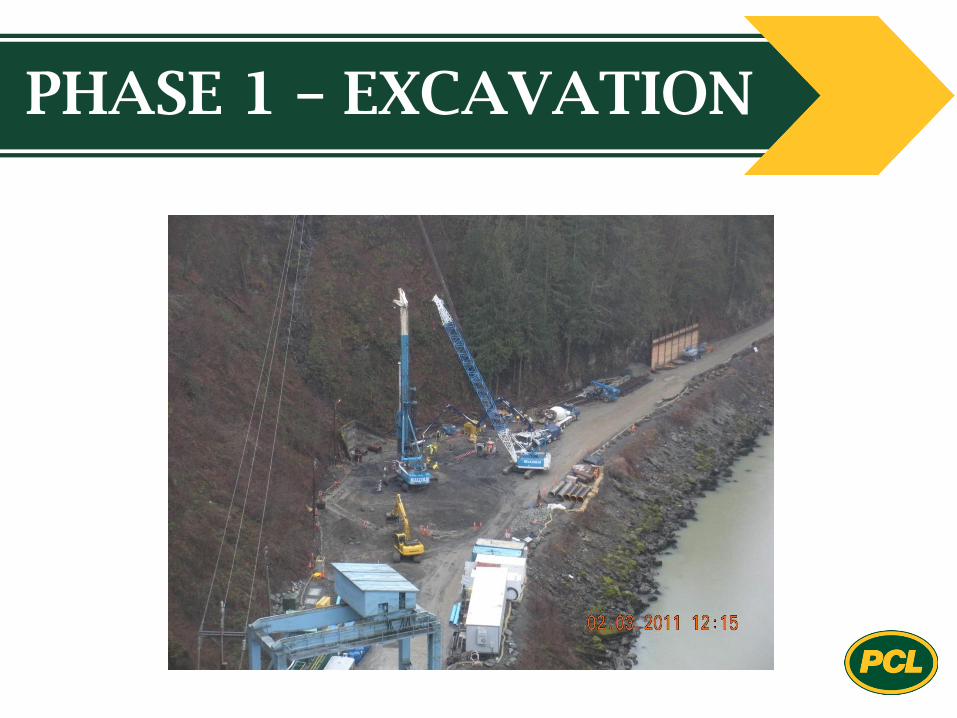
PHASE 1 – EXCAVATION
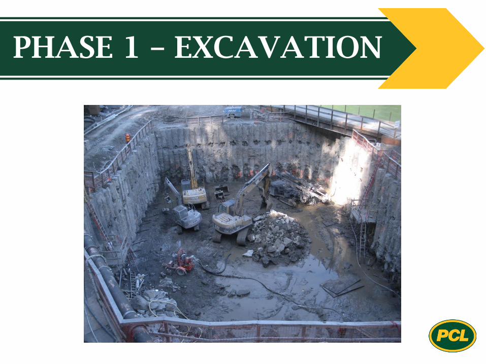
PHASE 1 – EXCAVATION
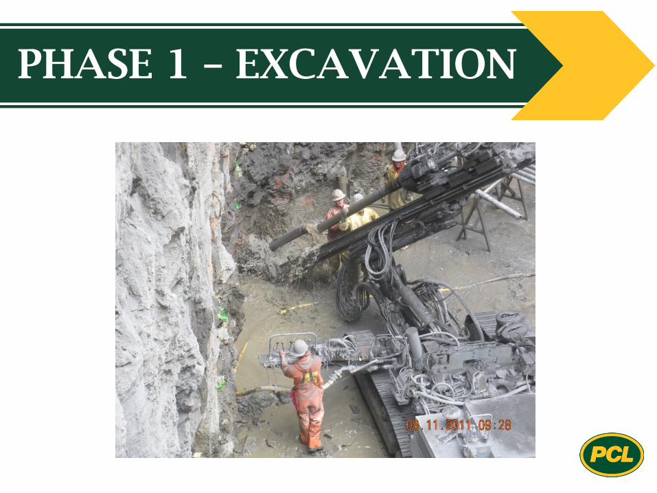
PHASE 1 – EXCAVATION
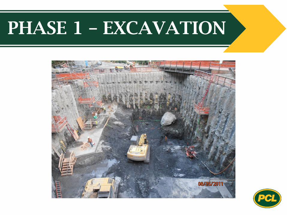
PHASE 1 – EXCAVATION
PHASE II – TUNNELING
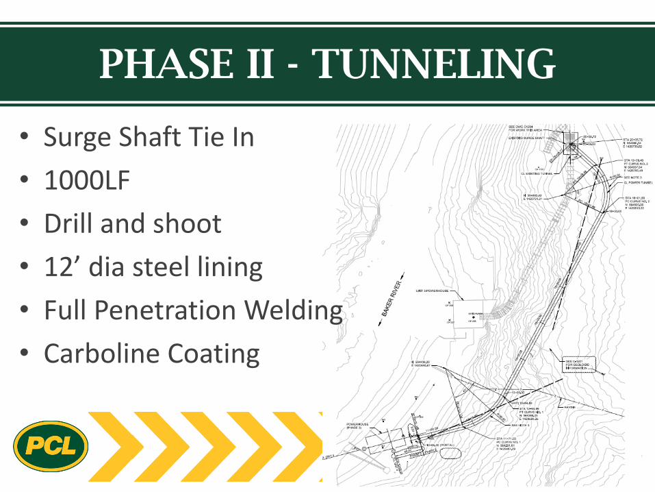
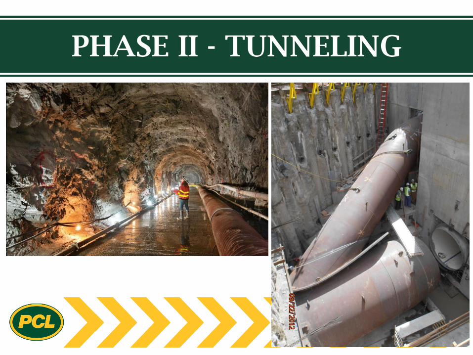
PHASE II - TUNNELING
• Surge Shaft Tie In
• 1000LF
• Drill and shoot
• 12’ dia steel lining
• Full Penetration Welding
• Carboline Coating
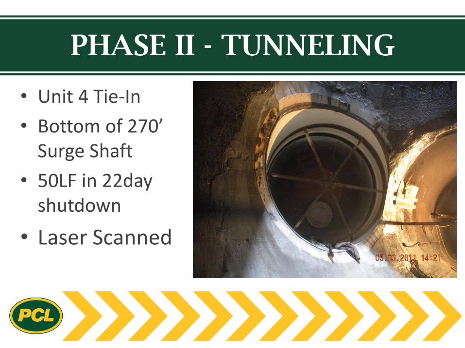
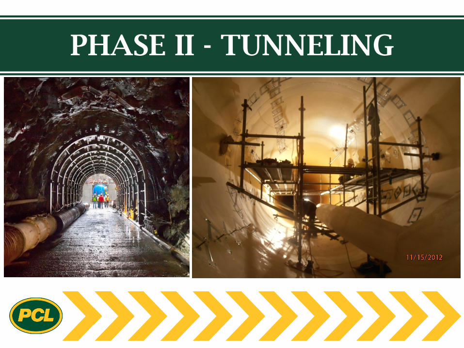
PHASE II - TUNNELING
• Unit 4 Tie-In
• Bottom of 270’ Surge Shaft
• 50LF in 22day shutdown
• Laser Scanned
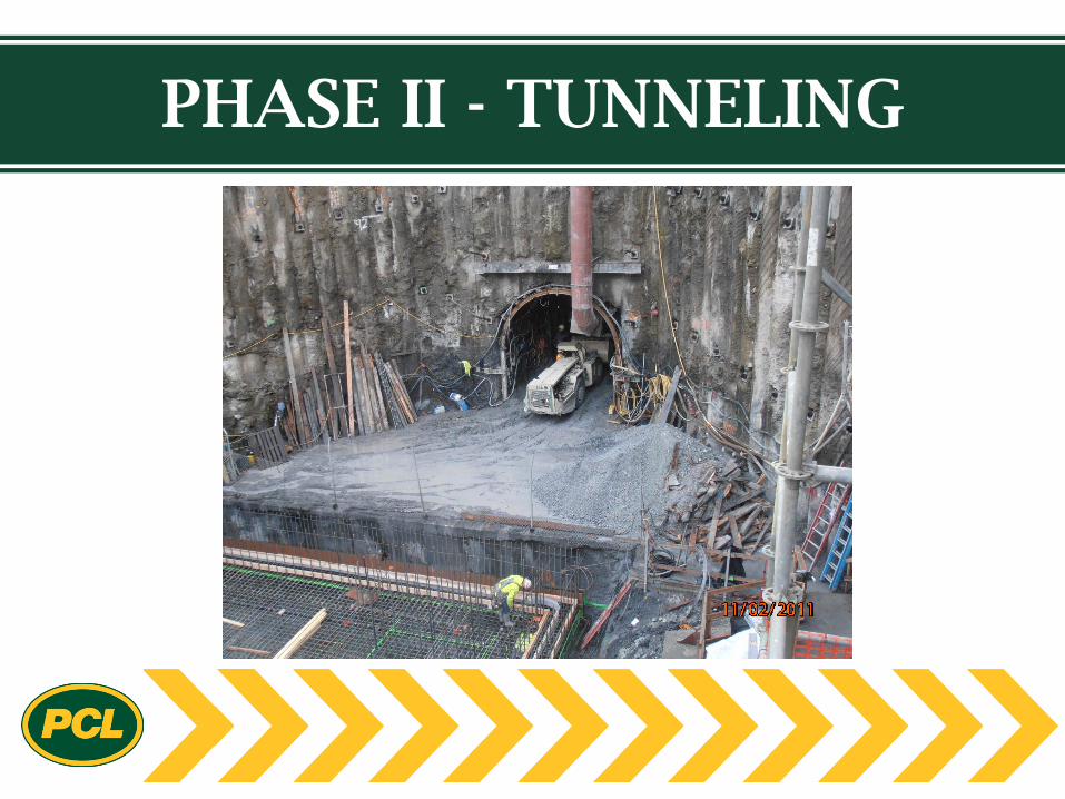
PHASE II - TUNNELING
PHASE II - TUNNELING
PHASE II - TUNNELING

PHASE III – POWERHOUSE
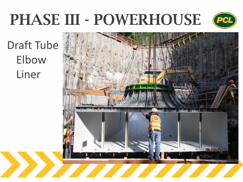
PHASE III - POWERHOUSE
Draft Tube Elbow Liner
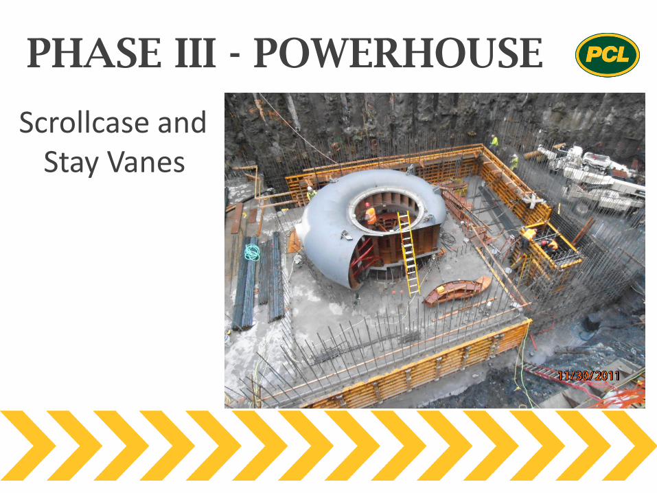
PHASE III - POWERHOUSE
Scrollcase and Stay Vanes
PHASE III - POWERHOUSE
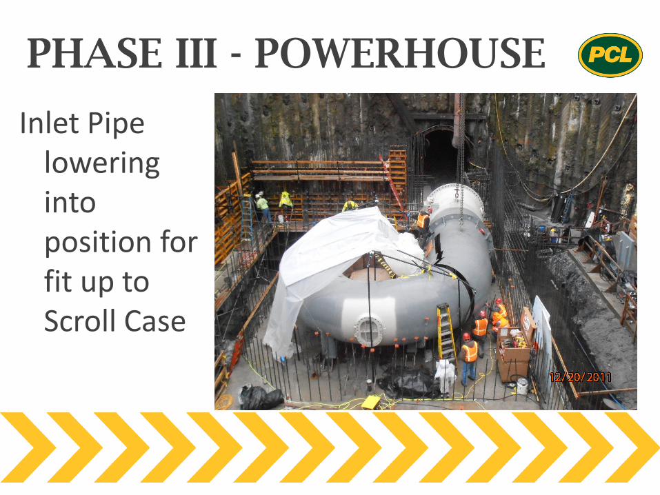
Inlet Pipe lowering into position for fit up to Scroll Case
PHASE III - POWERHOUSE
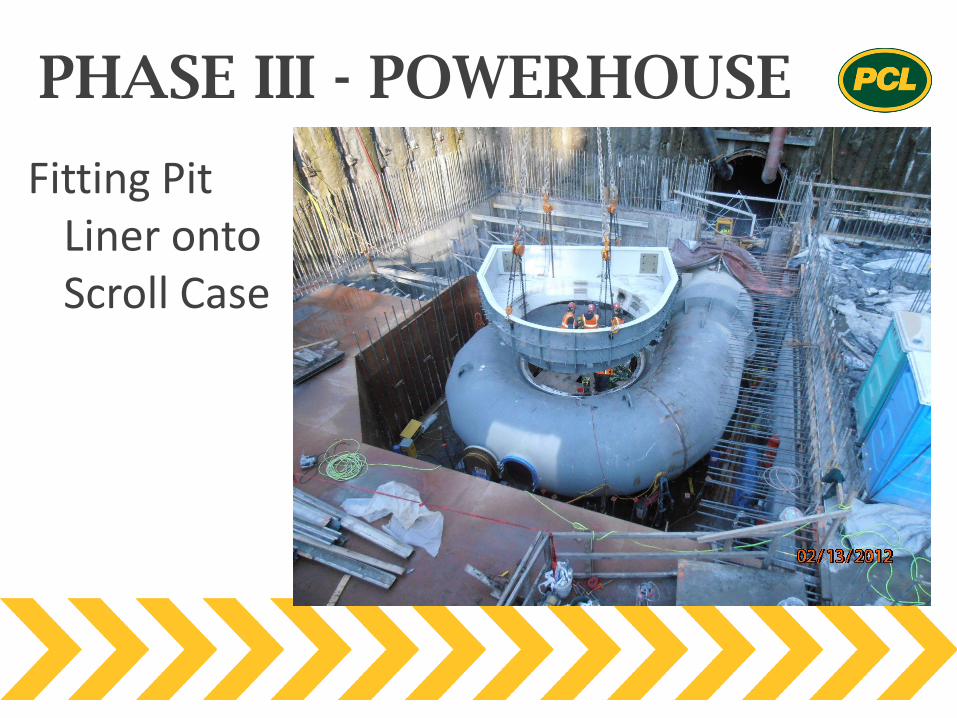
Fitting Pit Liner onto Scroll Case
PHASE III - POWERHOUSE
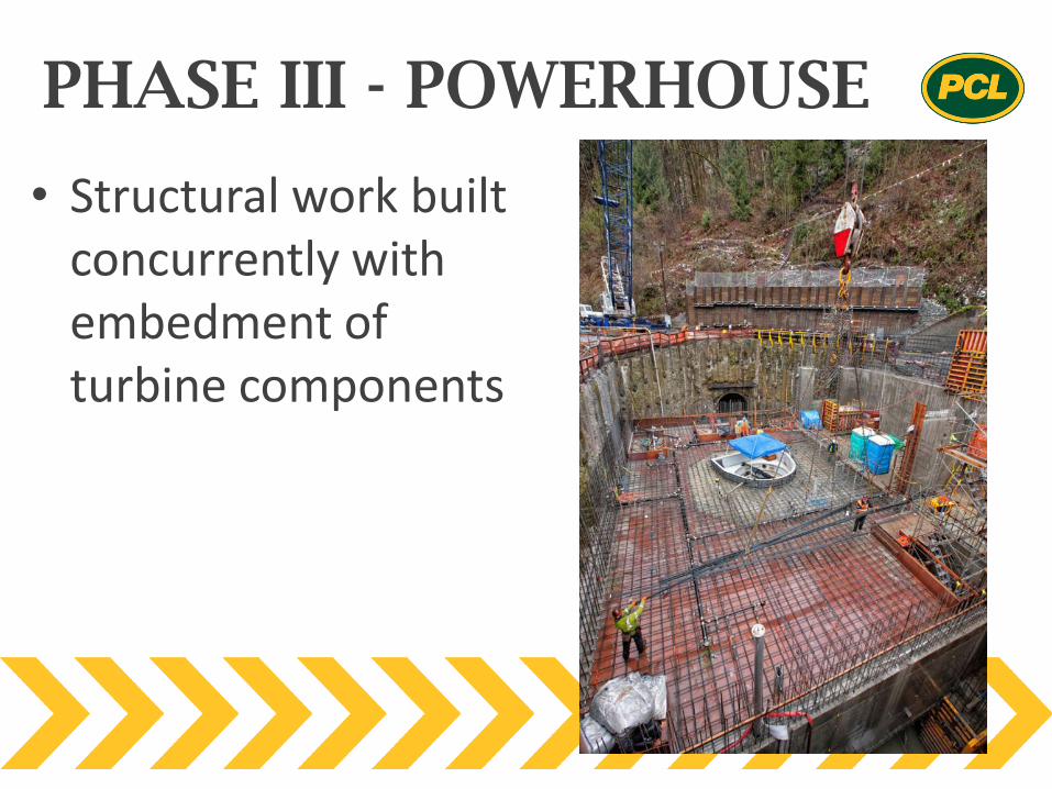
• Structural work built concurrently with embedment of turbine components
PHASE III - POWERHOUSE
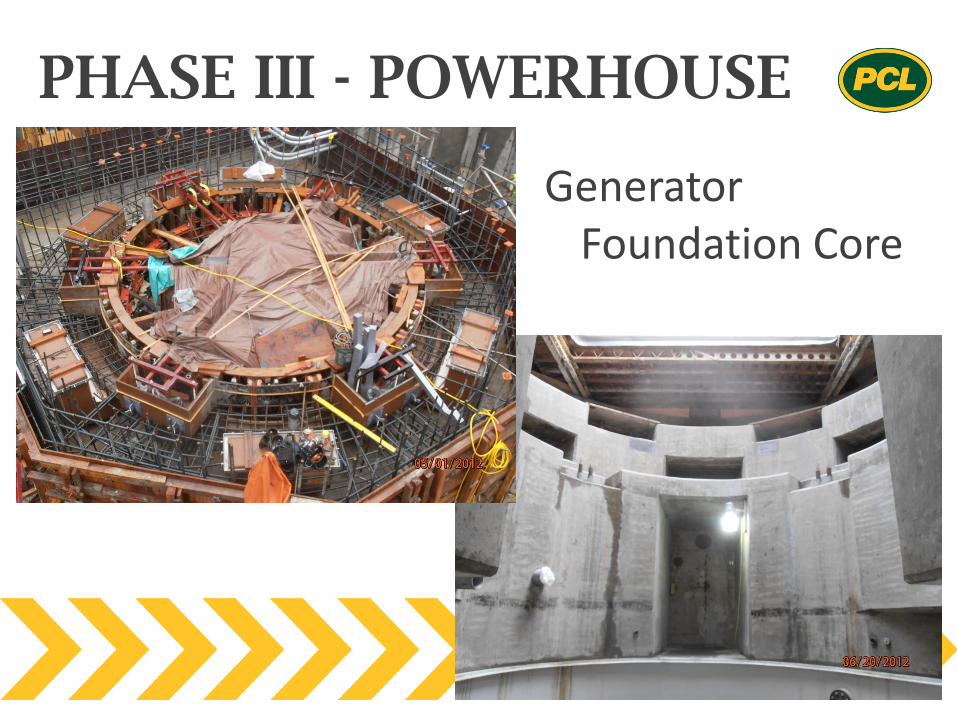
Generator Foundation Core
PHASE III - POWERHOUSE
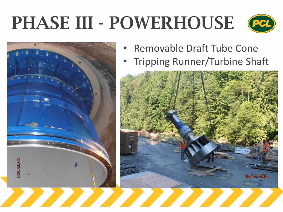
• Removable Draft Tube Cone • Tripping Runner/Turbine Shaft
PHASE III - POWERHOUSE
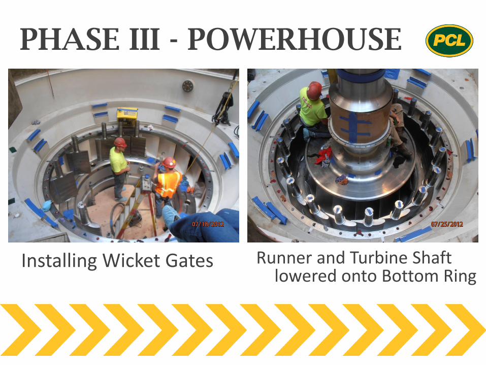
Installing Wicket Gates Runner and Turbine Shaft lowered onto Bottom Ring
PHASE III - POWERHOUSE
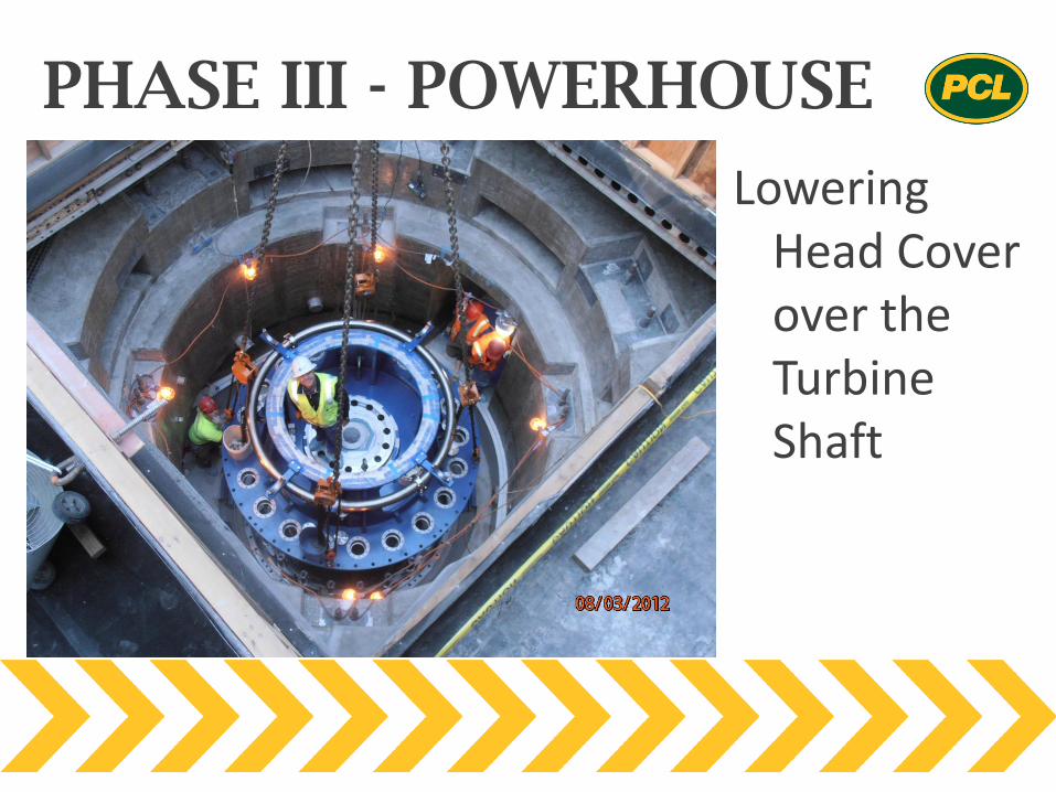
Lowering Head Cover over the Turbine Shaft
PHASE III - POWERHOUSE
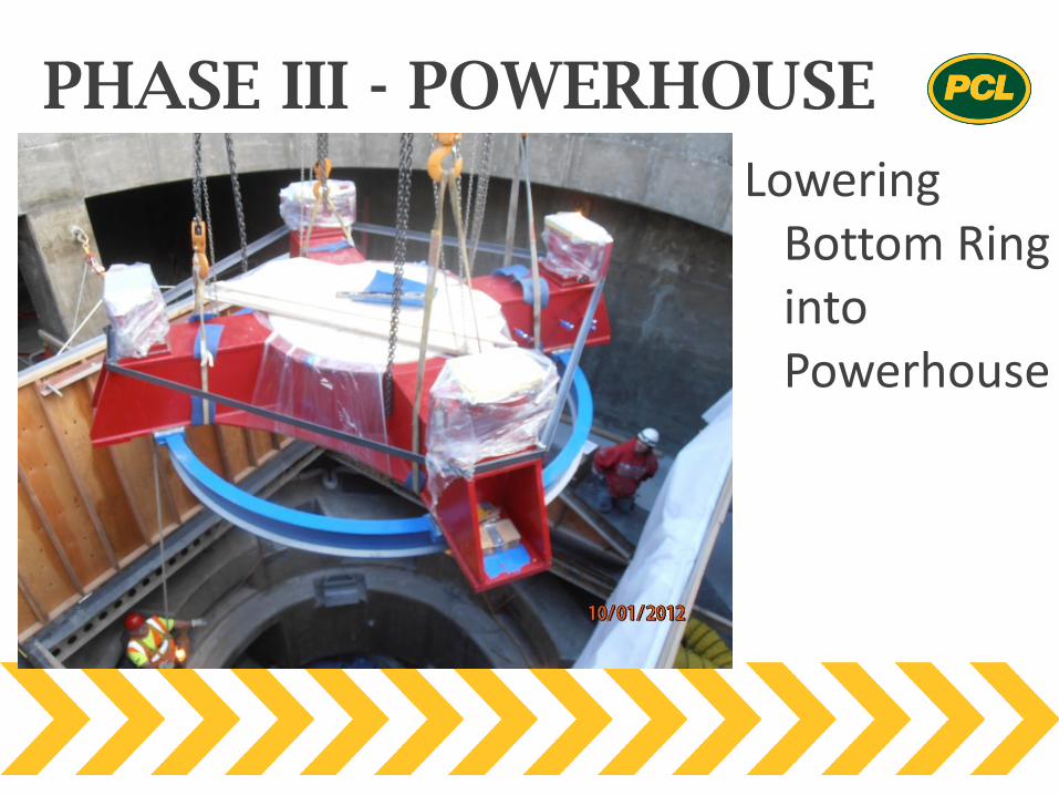
Lowering Bottom Ring into Powerhouse
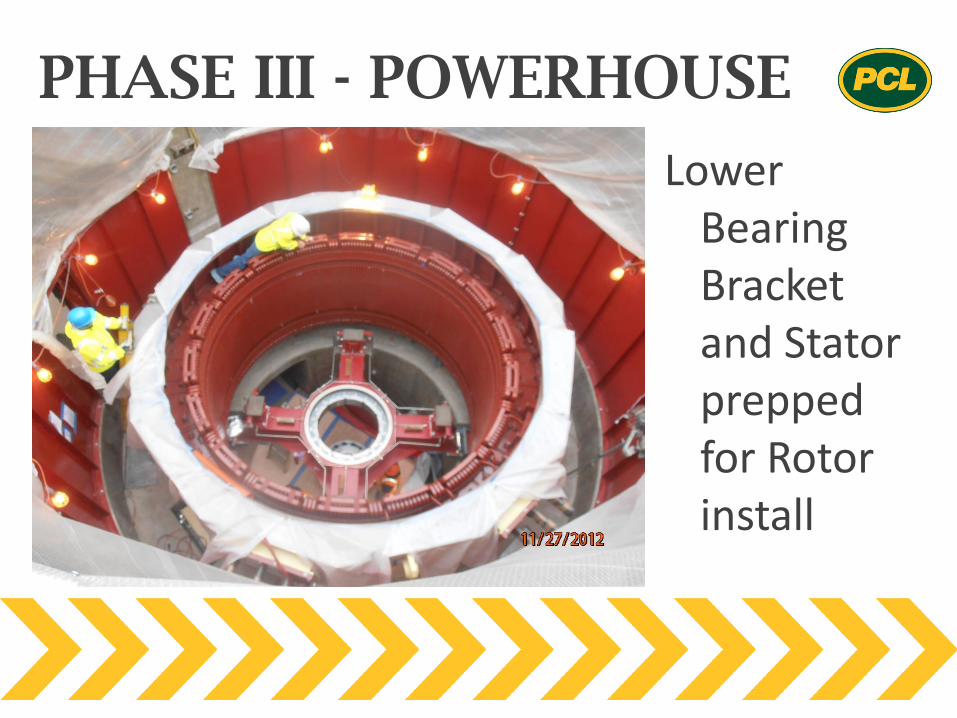
PHASE III - POWERHOUSE
Lower Bearing Bracket and Stator prepped for Rotor install
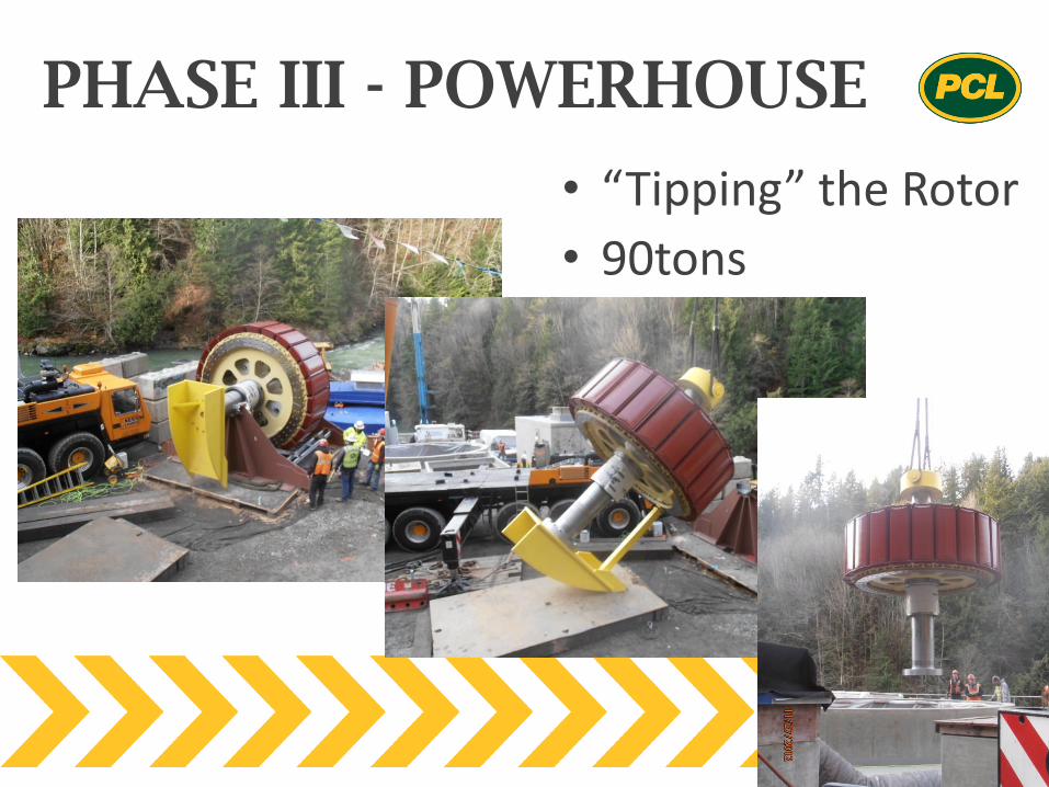
PHASE III - POWERHOUSE
• “Tipping” the Rotor
• 90tons
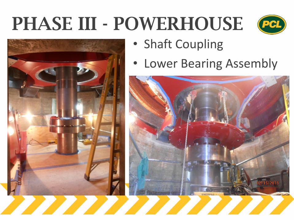
PHASE III - POWERHOUSE • Shaft Coupling
• Lower Bearing Assembly
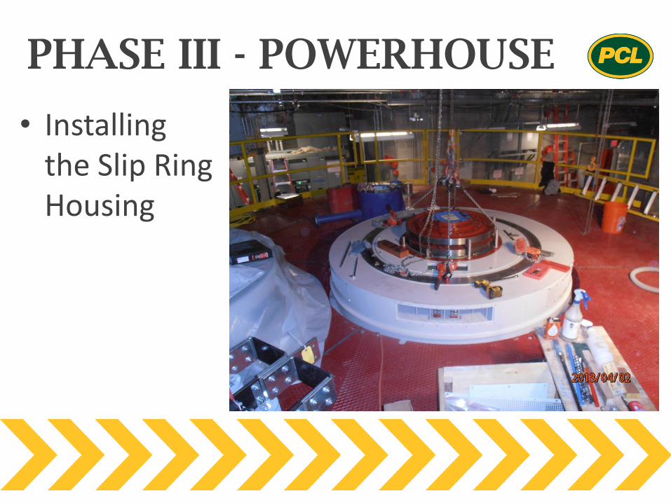
PHASE III - POWERHOUSE
• Installing the Slip Ring Housing
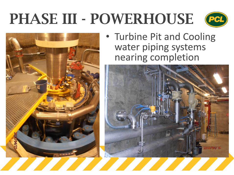
PHASE III - POWERHOUSE • Turbine Pit and Cooling
water piping systems nearing completion
PHASE III - POWERHOUSE
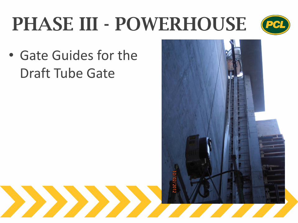
• Gate Guides for the Draft Tube Gate
PHASE III - POWERHOUSE
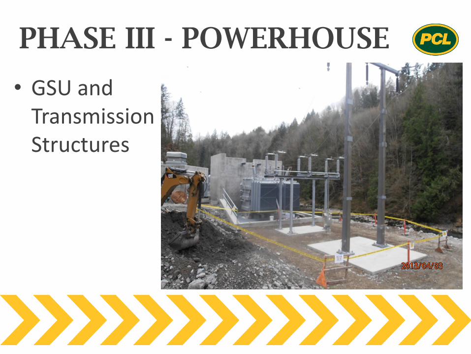
• GSU and Transmission Structures

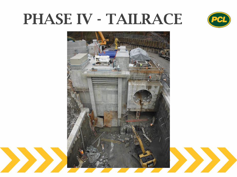
PHASE IV – TAILRACE
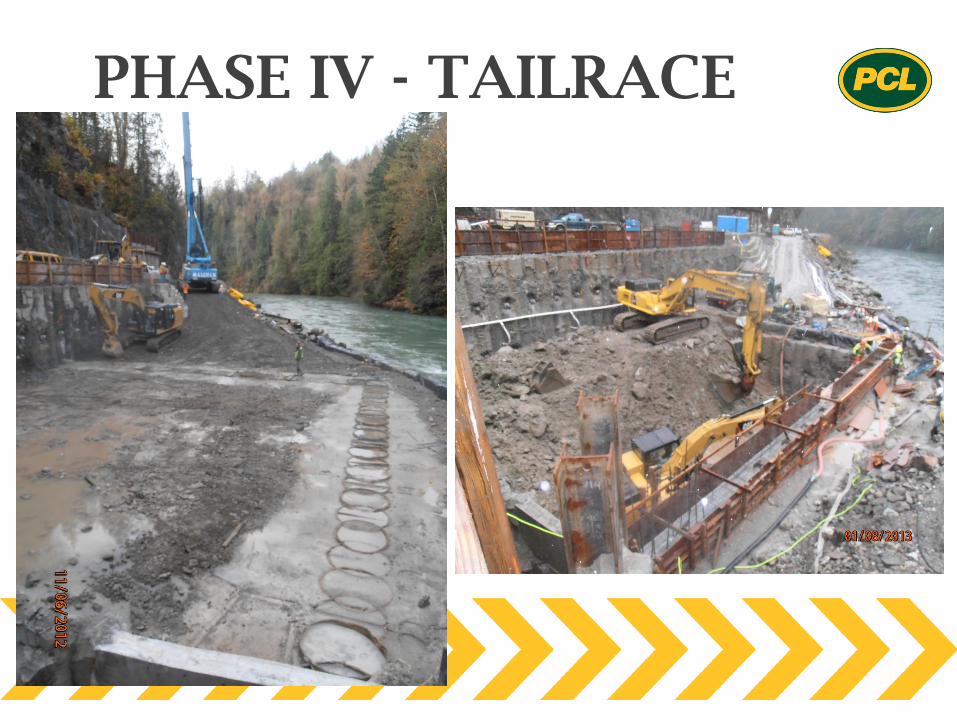
PHASE IV - TAILRACE
PHASE IV - TAILRACE
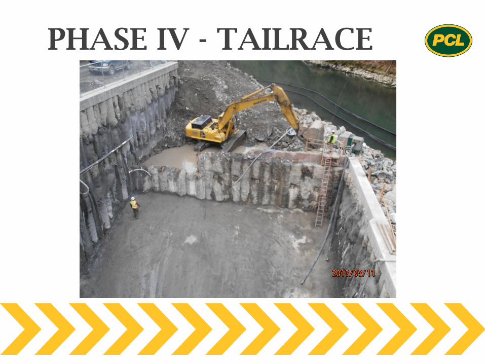
PHASE IV - TAILRACE
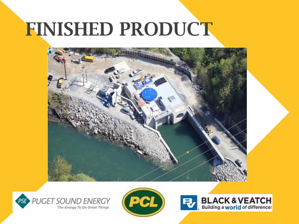
FINISHED PRODUCT
• Tunneling Operation Extremely Accurate
• Achieved all Tolerances in Stacking Unit
• Digital Upgrade of Unit 3 Control Room and hydraulic system
• Commercially Operational 100 days ahead of schedule
• Successful Overall Design Coordination with Owner provided Unit
• No interruptions to ongoing Unit 3 generation
SUCCESSFUL PROJECT

LOWER BAKER UNIT 4
POWERHOUSE
QUESTIONS?