Embed Size (px)
Citation preview

Royal Government of Bhutan
Ministry of Works and Human Settlement
Department of Roads
Construction, Operation & Maintenance of Dalbari –
Dagapela Secondary National Highway (0.000 - 80.580
km)
Volume II
PARTICULAR TECHNICAL SPECIFICATIONS FOR BRIDGE
WORKS
Section A: Dalbari-Odalthang

Page 1 of 69
Construction ,Operation & Maintenance of Dalbari-Odalthang SNH (Section A: 0.000 -29.000 Km)
ABBREVIATIONS
AASHTO American Association of State Highway and Transportation Officials AC Asphalt Concrete ACV Aggregate Crushing Value AIV Aggregate Impact Value ALD Average Least Dimension ASTM American Society of Testing and Materials BOQ Bill of Quantities BS British Standards BSCP British Standards Code of Practice BSR Bhutan Schedule of Rates CBR California Bearing Ratio c/c center to center CR Crushing Ratio Cu.m Cubic metre DCP Dynamic Cone Penetrometer DoFS Department of Forestry Services DOR Department of Roads DGM Department of Geology and Mines dia Diameter ECOP Environment Code of Practice for Highways and Roads EMP Environmental Management Plan FI Flakiness Index GCC General Conditions of Contract HMAC Hot mix asphalt concrete HWL High Water Level IRC Indian Road Congress (i.e. Recommended Code of Practice by IRC) IS Indian Standards ISO International Organization for Standardization LAA Los Angeles Abrasion Value LWL Low Water Level MC Moisture Content MDD Maximum Dry Density min Minute MSL Mean Sea Level NEC National Environment Commission no Number (units), as in 6 no. No Number (order) as in No 6 OMC Optimum Moisture Content OPC Ordinary Portland Cement PCC Particular Conditions of Contract PI Plasticity Index PL Plastic Limit PM Plasticity Modulus (PI x % passing 0.425 mm sieve) PVC Polyvinyle Chloride QA Quality Assurance PS Provisional Sum QC Quality Control

Page 2 of 69
Construction ,Operation & Maintenance of Dalbari-Odalthang SNH (Section A: 0.000 -29.000 Km)
RGoB Royal Government of Bhutan
RROW Road Right of Way
SE Sand Equivalent
sec Second
SG Specific Gravity
SI International Standard Units of Measurements
SSS Sodium Sulphate Soundness test, loss on 5 cycles
STV Standard Tar Viscosity
Sq.m Square metre
TS Tensile Strength
UC Uniformity Coefficient
UCS Unconfined Compressive Strength
VIM Voids in Mix
w/c Water cement ratio
Wt Weight
% Percent
Page 3 of 69
Construction ,Operation & Maintenance of Dalbari-Odalthang SNH (Section A: 0.000 -29.000 Km)
Table of Contents
1.0 SECTION 1: GENERAL AND SITE ESTABLISHMENTS 9
1.1 General 9
1.1.1 Scope of Work 9
1.1.2 Site Acquaintance 9
1.1.3 Specifications 9
1.1.4 Reference to Bureau of Indian Standards Codes & Other Codes 9
1.1.5 Dimensions & Levels 9
1.1.6 Notice of operation 9
1.1.7 Work program 9
1.1.8 Time Schedule 9
1.1.9 Drawings 10
1.1.10 Sub-Contracting 10
1.1.11 Compliance 10
1.1.12 Supply of Materials 10
1.1.13 Ordering Materials 10
1.1.14 Material Quality 10
1.1.15 Equipment & Facilities 11
1.1.16 Work Site Register (Site Order Book) 11
1.1.17 Area for the Contractor 11
1.1.18 Unit of measurement 11
1.2 Site Installations 11
1.2.1 Establishment of temporary infrastructure and facilities 11
1.2.2 Contractor’s site office 12
1.2.3 Labor Camps 12
1.2.4 Waste Management 12
1.2.5 Material Storage 12
1.2.6 Temporary Drainage System 12
1.2.7 Site Water Supply and Electricity 13

Page 4 of 69
Construction ,Operation & Maintenance of Dalbari-Odalthang SNH (Section A: 0.000 -29.000 Km)
1.2.8 Additional facilities to be provided 13
1.2.9 Survey Equipment 13
1.2.10 Sign Boards 13
1.2.11 Testing of Materials 14
1.3 General Contractor’s Obligations 16
1.3.1 Insurance 16
1.3.2 Safety measures and penalties 16
1.3.3 Protection of the Environment 16
1.3.4 Provision and Maintenance of labour Camps, waste management, material storage, temporary drainage system, water supply, electricity and communication facilities 17
1.3.5 As-Built Drawings 17
1.3.6 Maintenance and demobilization 17
1.4 Measurement and Payment 17
2.0 SECTION 2: EARTH WORKS 17
2.1 General 17
2.2 The Definition and Classification of materials for purpose of excavation shall be as follows: 18
2.2.1 Ordinary Soil (Normal Excavation) 18
2.2.2 Hard Soil (Intermediate Excavation) 18
2.2.3 Ordinary Rock (Intermediate Excavation) 18
2.2.4 Hard Rock (Hard Excavation) 18
2.2.5 Hard Rock ( Hard Excavation where blasting prohibited) 18
2.2.6 Marshy Soil 19
2.2.7 All Kinds of Soil 19
2.2.8 Authority for classification 19
2.3 Excavation 20
2.3.1 Setting out 20
2.3.2 Stripping and storing topsoil 20
2.3.3 Methods, tools and equipment 21
2.3.4 Rocks excavation 21
2.3.5 Marsh excavation 21
Page 5 of 69
Construction ,Operation & Maintenance of Dalbari-Odalthang SNH (Section A: 0.000 -29.000 Km)
2.3.6 Blasting 21
2.3.7 Cutting 22
2.3.8 Disposal of Excavated Material 22
2.3.9 Pumping and Bailing 22
2.3.10 Foundation Fill Material 23
2.3.11 Backfill Material 23
2.3.12 Backfilling 23
2.4 Measurements and Payments 24
3.0 SECTION 3: STRUCTURRES 25
3.1 Concrete for structures 25
3.1.1 Standards 25
3.2 Description 25
3.3 Materials 25
3.3.1 Specifications for Materials 25
3.3.2 Testing of Materials 28
3.3.3 Composition of Concrete 29
3.3.4 Control of Concrete Quality 32
3.4 Construction Methods 34
3.4.1 General 34
3.4.2 Care and Storage of Concrete Materials 34
3.4.3 Preparations before Casting 35
3.4.4 Measuring Materials 35
3.4.5 Mixing Concrete 35
3.4.6 Handling and Placing Concrete 38
3.4.7 Perforations and Embedment of Special Devices 41
3.4.8 Finishing Concrete Surfaces 41
3.4.9 Construction Joints 42
3.4.10 Curing Concrete 43
3.4.11 Removal of Scaffolding and Formwork 43
3.4.12 Repair of Concrete 43

Page 6 of 69
Construction ,Operation & Maintenance of Dalbari-Odalthang SNH (Section A: 0.000 -29.000 Km)
3.4.13 Depositing Concrete under Water 44
3.4.14 Factory Made Precast Concrete Elements 44
3.4.15 Control of Heat in Structures 45
3.4.16 Loading 45
3.4.17 Backfill to Structures 45
3.4.18 Cleaning Up 45
3.5 Measurement and Payment 45
3.6 Formwork and Scaffolding 46
3.6.1 Scaffolding (Falsework) 46
3.6.2 Formwork 47
3.6.3 Surface Treatment for Shuttering 48
3.6.4 Camber 48
3.6.5 Approval of Scaffolding and Formwork 48
3.6.6 Special Formwork 49
3.6.7 Removal of Form Work 49
3.7 Measurements and Payment 50
3.8 Reinforcement 50
3.8.1 Description 50
3.8.2 Materials 50
3.9 Construction Methods 51
3.10 Measurement and Payments 52
4.0 SECTION 4: MISCELLANEOUS 53
4.1 Drainage for Structures 53
4.1.1 Description 53
4.1.2 Drainage Spouts 53
4.2 Measurements and Payments 54
4.3 Open surface drains 54
4.3.1 General requirements 54
4.3.2 Scope 54
4.3.3 Excavation 54
Page 7 of 69
Construction ,Operation & Maintenance of Dalbari-Odalthang SNH (Section A: 0.000 -29.000 Km)
4.4 Measurement and Payment 54
4.5 HDPE drainage pipes 55
4.5.1 Scope 55
4.5.2 Material 55
4.5.3 Placement 55
4.6 Measurement and Payment 55
4.7 Gabion protection works 55
4.7.1 Scope 55
4.7.2 Materials 55
Construction of Gabions 57
4.8 Measurement and Payment 60
4.9 Elastomeric Bridge Bearings 60
4.9.1 Scope 60
4.9.2 Steel reinforced Elastomeric Bearings 60
4.9.3 Properties of Elastomer 61
4.9.4 Steel Laminates 61
4.9.5 Bond 61
4.9.6 Manufacture 61
4.9.7 Fabrication Tolerances 61
4.9.8 Marking and Certifying 62
4.9.9 Testing 62
4.9.10 Installation 63
4.10 Measurement and Payment 63
4.11 Movement or Expansion Joints 63
4.11.1 Scope of Work 63
4.11.2 Specification for Strip Seal Expansion Joint 64
4.12 Measurement and Payment 67
5.0 SECTION 5: DAY WORKS 67
5.1 General 67
5.2 Dayworks Labour 67
Page 8 of 69
Construction ,Operation & Maintenance of Dalbari-Odalthang SNH (Section A: 0.000 -29.000 Km)
5.3 Dayworks Materials 68
5.4 Dayworks Plant 68
LIST OF TABLES
Table 2.3-1 Grading of foundation fill material .................................................................. 23
Table 3.3-1 Grading Requirements Coarse Aggregate ................................................... 27
Table 3.3-2 Grading Requirements for Fine Aggregate .................................................. 28
Table 3.3-3 Concrete classes .............................................................................................. 30
Table 3.8-1 Removal of Form Work ................................................................................... 49
Table 4.3-1 Strip Seal Element Specifications ................................................................. 65
Page 9 of 69
Construction ,Operation & Maintenance of Dalbari-Odalthang SNH (Section A: 0.000 -29.000 Km)
1.0 SECTION 1: GENERAL AND SITE ESTABLISHMENTS
1.1 General
1.1.1 Scope of Work
The Scope of work covered by his specifications is to execute the construction of bridges on Dalbari-
Dagapela Secondary Highway (0.000 - 80.580 Km)
1.1.2 Site Acquaintance
The Contractor shall be deemed to have made himself /herself fully acquainted with the full nature of
the work, the location & character of the bridge site & means of access to the site, including any traffic
restrictions imposed. The construction site is an area within 5kms radius of the location of the bridge.
1.1.3 Specifications
The work shall be executed in accordance with the technical specifications, the drawings, the Bill of
Quantities & the instructions issued by the Client from time to time. Wherever these specifications are
found wanting in anyway, the latest edition of standard specification for Bridges as approved by the
Client shall be followed.
1.1.4 Reference to Bureau of Indian Standards Codes & Other Codes
The Standard Specifications & Codes of Practices explicitly referred to in these Specifications or other
related standard codes etc. shall be of latest editions, current at the time of tendering including all
amendments published before that date.
1.1.5 Dimensions & Levels
All dimensions & levels shown on the Drawings shall be verified by the Contractor at the site & he/she
will be held responsible for the accuracy & maintenance of all dimensions & levels. Figured
dimensions are in all cases to be accepted & no dimensions shall be scaled. Large scale details shall
take precedence over small scale drawings. In case of discrepancy the Contractor shall ask for
clarifications from the Project Manager before proceeding with the work.
1.1.6 Notice of operation
The Contractor shall not carry out important operations without the consent in writing of the Project
Manager.
1.1.7 Work program
The Contractor shall submit to the Project Manager before commencement of the work, for his
approval, a detailed program in the form of bar chart/Microsoft project etc. The submission & approval
of such program shall not relieve the Contractor of any of his duties or responsibilities under the
Contract.
1.1.8 Time Schedule
The Contractor shall follow the project master schedule & detailed activity schedule submitted after
signing the contract. The contractor may submit minor changes on schedule to the Project manager
for approval whenever necessary.
Page 10 of 69
Construction ,Operation & Maintenance of Dalbari-Odalthang SNH (Section A: 0.000 -29.000 Km)
1.1.9 Drawings
The Contractor will receive free of cost one complete set of all drawings necessary to complete the
work and the Contractor have to include in his Tender for any additional copies of drawings required
by him. One copy of the full set of drawings shall be retained at the site.
1.1.10 Sub-Contracting
Should the Contactor consider it necessary to sub-contract any part of his work, the Sub-Contractor &
the scope of the work proposed to be sub contracted has to be approved by the Project
Manager/Client. It will be the responsibility of the Contractor to ensure that the sub-contracted works
are carried out in accordance with the specifications & relevant drawings.
1.1.11 Compliance
All workmanship, materials & tests (where required) shall comply with the appropriate Indian or
American Standards as specified or approved & shall be in accordance with the drawings all to the
satisfaction of the Client/Project Manager.
1.1.12 Supply of Materials
a. The Contractor shall supply certificates of compliance with specified Indian Standards for all
materials supplied for the works. Manufacturer’s catalogues & samples of materials proposed
for procurement & to be used in the works shall be submitted to the Client for approval, before
procurement.
b. Materials procured without specific approval of the Client shall not be allowed to be used in the
works.
c. The Contractor’s quoted rate shall include but not limited to:
i. Preparation & submission of shop drawings wherever necessary, calculation sheets,
schedule of materials, & providing catalogues about, & samples of materials, & obtaining
approval from the Client.
ii. Carryout of mix design, sampling and testing of construction materials, preparation and
testing of trial mixes, preparation and testing of concrete test cubes, and obtaining
approval from the Client.
iii. Transporting to the Site, including loading & unloading.
iv. Providing certificates of compliance with required relevant standards, as specified.
v. Storing & protection of the materials at the Site.
1.1.13 Ordering Materials
The Contractor is entirely responsible for assessing the quantities of materials to be ordered for use in
the works.
1.1.14 Material Quality
The Contractor should note that the qualities of all materials used shall be scrutinized, monitored &
checked by the Client. All materials used have to fulfill the requirements & specifications given in the
drawings & in the relevant code of practice. If the Contractor is asked to supply certificate of origin of
the supplied & used materials, he has to do so within a reasonable timeframe fixed by the Project
Manager.
Page 11 of 69
Construction ,Operation & Maintenance of Dalbari-Odalthang SNH (Section A: 0.000 -29.000 Km)
1.1.15 Equipment & Facilities
The Contractor shall provide & operate equipment & facilities to load, offload, shift, move, transport,
stack & place all types of steel parts & materials at the bridge site as well as at the Contractor’s yard.
The Contractor shall also provide all lifting equipment & facilities to lift, shift, stack, load, unload &
handle all type of steel parts & materials at the bridge site as well as at the Contractor’s yard.
1.1.16 Work Site Register (Site Order Book)
The Contractor shall keep a Work Site Register (Site Order Book) at the Site in which all the remarks,
instructions, decisions of the Client & the essential details of the work shall be recorded. The
Contractor shall keep the records of all daily information of the works in this register as required by the
Client. It shall be readily available in the office for inspection.
1.1.17 Area for the Contractor
i. The Contractor shall be allocated an area for his equipment, materials & site offices in the
vicinity of the bridge site.
ii. The Contractor shall maintain a properly furnished office, which will include but not necessarily
limited to lock up drawers for construction drawings, filing cabinets, large sized soft board
panels etc., with toilet facility in the allocated area at the site for his own use as well as for use
of the Client & his representatives. These shall be provided by the Contractor at no extra cost.
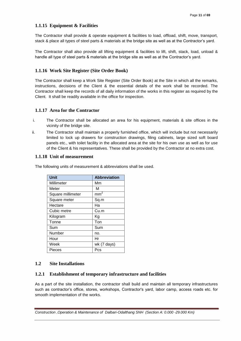
1.1.18 Unit of measurement
The following units of measurement & abbreviations shall be used.
Unit Abbreviation
Millimeter Mm
Meter M
Square millimeter mm2
Square meter Sq.m
Hectare Ha
Cubic metre Cu.m
Kilogram Kg
Tonne Ton
Sum Sum
Number no.
Hour Hr
Week wk (7 days)
Pieces Pcs
1.2 Site Installations
1.2.1 Establishment of temporary infrastructure and facilities
As a part of the site installation, the contractor shall build and maintain all temporary infrastructures
such as contractor’s office, stores, workshops, Contractor's yard, labor camp, access roads etc. for
smooth implementation of the works.
Page 12 of 69
Construction ,Operation & Maintenance of Dalbari-Odalthang SNH (Section A: 0.000 -29.000 Km)
The following facilities, but not limited to, shall be installed/built and maintained by the contractor as a
part of the site installation:-
1.2.2 Contractor’s site office
The contractor shall build and maintain a site office with sanitary facilities during the project duration.
The site office shall have a minimum plan area of 50m2 and shall have at least concrete flooring,
bamboo mat or ekra wall and CGI roof. The contractor’s site office shall have minimum following
facilities:-
i. Desk top computer set with sufficient capacity to run standard engineering softwares such as
AUTO CAD, LISCAD etc. - 1 no.
ii. A3 printer - 1 no.
iii. Photocopy Machine - 1 no.
iv. Scanner - 1 no.
v. Internet connection (subject to availability of the facility at the project site)
vi. Tables and chairs sufficient to conduct site meetings between the contractor and the
representatives of the Client
1.2.3 Labor Camps
Labor camps with sufficient and maintained sanitary facilities, sufficient & safe drinking water and
sufficient supply of electric power have to be made available at all times during the project duration.
The labor camps shall at least have concrete flooring, bamboo mat wall and CGI roof. The size and
number of such camps shall be approved by the Project Manager based on the labor strength
requirement after contractor submits the master work plan
1.2.4 Waste Management
A proper waste management facility and system have to be put in place to maintain general
cleanliness of the site and upkeep hygiene of the personnel and laborers working at the bridge site.
The proposed facilities has to be approved by the Project Manager.
1.2.5 Material Storage
Construction materials have to be stored well under sheds to avoid quality drops and loss.
Minimum following facilities have to be erected at the bridge site as a part of site installation for
material storage:-
i. Cement store – min. plan area 50m2, CC flooring, tin wall & roof (water tight and limited air
circulation) - 1 no.
ii. General store – min. plan area 25m2, CC flooring, bamboo mat/ekra wall and tin roof
- 1 no.
1.2.6 Temporary Drainage System
The Contractor shall build a temporary drainage system at the site to drain out waste water. The
layout and design of the drains have to be approved by the Project Manager.

Page 13 of 69
Construction ,Operation & Maintenance of Dalbari-Odalthang SNH (Section A: 0.000 -29.000 Km)
1.2.7 Site Water Supply and Electricity
The Contractor shall make his own connections for water and electric supply and pay for them.
The water supplied must be potable and must be free from salts, oils, acids, arsenic and other
substances harmful to health. The water shall be tested to confirm its portability
If electricity is not available at the bridge site, the Contractor shall install generators of sufficient
number and capacity to power all the facilities at the bridge site such as the Project Manager’s Office,
Contractor’s office, laboratory, labor camps, stores etc. If the Contractor intends to use electrically
operated construction equipment and machinery, matching number and capacity of generators have
to be installed at the bridge site.
1.2.8 Additional facilities to be provided
As a part of the site installation, the contractor shall provide/build/install following additional facilities:-
1.2.9 Survey Equipment
The Contractor will be required to provide survey equipment for the use of the Contractor and Project
Manager and his staff. The equipment and all its accessories shall be available at all times at the
bridge site during the contract period and shall be maintained in good working order. For higher
accuracy and better ease of use, the equipment shall be Total Station or equivalent. The contractor
shall depute appropriately qualified and trained personnel to operate the survey equipment at all times
during the contract period.
The survey equipment and its accessories (legs, reflectors and stands, rechargeable batteries and
charger etc.) shall be from any reputable manufacturer. The range, accuracy, least count etc. of the
equipment has to be approved by the Project Manager.
1.2.10 Sign Boards
The Contractor shall provide identification sign boards and maintain them in good condition. All
information on the signboards will be written in English and Dzongkha. The signboards will be
positioned as directed by the Project Manager.
Each sign shall show:
the name of the Project
the name of the Employer
name of the Contractor
Contract start and completion dates
Contract amount
Any other details as required by the Project Manager
Project Signboards shall have steel pipe posts of diameter from 75mm to 100mm with 3mm thick steel
plates. The steel pipe legs shall be embedded in the ground. The design of the signpost and the
information content on it shall be approved by the Project Manager.
The contractor shall install at least one sign board at the bridge site, the location of which shall be
approved by the Project Manager.
Page 14 of 69
Construction ,Operation & Maintenance of Dalbari-Odalthang SNH (Section A: 0.000 -29.000 Km)
The Contractor shall remove the sign boards on completion of the Works or when instructed by the
Project Manager
1.2.11 Testing of Materials
1.2.11.1 Contractor’s Site Laboratory
The Contractor shall provide and maintain a Site Laboratory in a semi-permanent building of about
25m2 plinth area with concrete floor, bamboo mat wall & CGI roof for the use of the Contractor and the
Project Manager.
The laboratory shall have furniture, testing equipment and consumable stocks necessary to carry out
the tests listed below:-
1. Moisture Content
2. Particle Size Distribution
3. Standard Compaction
4. Flakiness Index
5. Fineness Modulus
6. Aggregate Crushing Value
7. Slump Test
8. Concrete Crushing Strength
The Contractor would be required to mobilize, but not limited to, the following equipment for quality
assurance tests both at site and at the site laboratory as a part of site installation:
1. Moisture can
2. Weighing balance (accuracy 0.01 gm)
3. 1000 ml glass cylinder with rubber bung
4. Graduated measuring cylinder
5. Hydrometer
6. Thermometer
7. Sample tray
8. Straight edge knife
9. Scoop
10. Mixing trowel
11. Sand pouring cylinder with lid
12. Metal tray
13. Flakiness index gauge
14. Sieve set
15. Slump cone
16. Scale
17. Concrete crushing machine
Page 15 of 69
Construction ,Operation & Maintenance of Dalbari-Odalthang SNH (Section A: 0.000 -29.000 Km)
18. Concrete cube mould
19. Tamping rod
20. Hand gloves & filter papers
21. Concrete thermometers
The Contractor shall provide a sufficient number of cube moulds to meet the testing frequency
requirements for the concrete pour program for all the sites under the Contract. A reasonable number
of spare moulds should also be available for any ‘ad hoc’ testing that may be required.
The laboratory shall be housed inside a proper shelter. The layout, size and location of the site
laboratory have to be approved by the Project Manager.
The Contractor shall maintain the laboratory, furniture, fittings and testing equipment for the duration
of the Contract and replace any part or item that is irreparably damaged or lost. The Contractor shall
pay all expenses in respect of water, electricity and other consumables necessary for the running of
the laboratory and shall arrange for the laboratory to be regularly cleaned.
The Contractor shall not be permitted to commence permanent works requiring on-site testing till the
Site laboratory is complete in all respects, unless temporary testing procedures proposed by the
Contractor have been approved by the Project Manager.
At the end of the Contract, all materials recovered from dismantling the laboratory, together with all
furniture, fittings and testing equipment will remain the property of the Contractor.
1.2.11.2 Materials Testing by Independent Laboratories
In addition to the above mentioned tests the Contractor shall arrange for the following tests to be
carried out at off-site testing facilities as and when instructed by the Project Manager:
1. Tests on reinforcing steel
2. Tests on cement – fineness, setting time and strength
3. Aggregate crushing value
4. Any other tests as may be decided by the Project Manager
The Contractor shall be responsible for arranging off-Site laboratory tests, and all other tests indicated
as the responsibility of the Contractor in different Sections of the Specifications. These tests shall be
performed by off-site standard testing laboratories proposed by the contractor and as approved by the
Project Manager. All the expenses for such tests shall be borne by the contractor. The Contractor
shall be responsible for all attendance of staff from these approved testing laboratories, including if
necessary the provision of transport for personnel, equipment and test specimens.
1.2.11.3 Staff for Materials Testing
The laboratory engineers and technicians shall be provided by the contractor to carry out sampling
and testing of materials in accordance with Specifications Sections, 1.2.11.1, and
1.2.11.4 Sampling and Testing
For Concrete Mixes 1 set of tests per 100 m3
of aggregate for shape, grading, ACV / 10% Fines
should be carried out.
Page 16 of 69
Construction ,Operation & Maintenance of Dalbari-Odalthang SNH (Section A: 0.000 -29.000 Km)
The Contractor shall maintain complete records of test results, which may be inspected by the Project
Manager at any time. All test results shall be recorded on standard forms approved by the Project
Manager and shall be signed by the Contractor’s engineer or technician in charge of the laboratory.
Completed forms shall clearly show the locations of samples, sampling dates and testing dates.
Samples shall be numbered serially at the time of sampling. A copy of all test results should be
submitted to the Project Manager immediately after completion of the test.
The Project Manager will be informed prior to any sampling or testing carried out in the laboratory and
will have the right to use the facilities and equipment to make his own tests. The Contractor shall have
the right to witness any sampling or testing carried out by the Project Manager. On completion of the
Contract the original copies of all test results shall be handed over to the Employer, via the Project
Manager.
1.3 General Contractor’s Obligations
1.3.1 Insurance
The contractor shall obtain all risk insurance for the work, plant, equipment, personnel and labor. The
modalities for the insurance shall be as per the stipulations under Clause 13 of General Conditions of
Contract (GCC).
1.3.2 Safety measures and penalties
The regulations and guidelines for Work Place Safety issued by Ministry of Labor and Human
Resources, RGoB shall be complied with at all times. The workers and the personnel shall have safe
and secure working conditions at the construction site at all times and there shall be no compromise
on the work place safety. The workers shall wear safety gears – helmets, boots, belts, goggles, hand
gloves, welding masks etc. as may be appropriate, at the work site at all times.
The Contractor shall issue the required protective clothing and safety equipment to all his employees
and provide the first aid boxes within one month of the commencement of the Contract. He is
responsible for ensuring that all his employees make appropriate use of the items and maintain them
in good order. The Contractor shall replace damaged, worn-out, exhausted or out of date items as
necessary.
The Contractor shall build temporary scaffold, temporary stairs, working platforms, fall-down-stoppers
and such other measures to allow safe and proper execution and check of the construction works.
Anybody entering the worksite shall wear safety helmets at all times. If scaffold, working platforms etc.
are not possible or not required, the personnel and the workers have to wear safety belts. The quality
of the safety belts has to be approved by the Project Manager.
1.3.3 Protection of the Environment
The Contractor has to allow for complying with his obligations for safety, security and protection of the
environment described in the Contract Documents included in the related Sub-Clauses of the
Conditions of Contract. The Contractor is not allowed to dispose or dump any kind of waste materials
into the river. The contractor has to, at the end of the project, remove and clean the waterway of all
the temporary constructions that it has built for the purpose of securing temporary supports or
restraints for the permanent structures, installations for safety measures etc. and which do not
ultimately form the part of the permanent structure.
Page 17 of 69
Construction ,Operation & Maintenance of Dalbari-Odalthang SNH (Section A: 0.000 -29.000 Km)
1.3.4 Provision and Maintenance of labour Camps, waste management, material
storage, temporary drainage system, water supply, electricity and communication
facilities
The Contractor shall provide labour camps, waste management system, material storage facility,
temporary drainage system, water supply, electricity and communication facilities as outlined in sub-
clause 1.2
1.3.5 As-Built Drawings
The Contractor shall furnish sets of as-built Drawings of the Works to the Project Manager, showing
the permanent works as actually constructed, within one month of completion of the Works. Included
in the sets of as-built Drawings will be revisions of Tender Drawings and Drawings supplied to the
Contractor during the Contract as well as revisions of drawings supplied by the Contractor during the
Contract. The As-built drawings submitted by the Contractor will be subject to the approval of the
Project Manager.
1.3.6 Maintenance and demobilization
The Contractor shall properly maintain all the infrastructures built at the site such as office, stores,
yards, labor camps etc. till the end of the Project. At the end of the Project, the Contractor has to
remove and demobilize all the temporary infrastructures that it has built and restore the bridge site to
its original condition and shape. The dismantling and demobilization shall be completed within the
stipulated contract duration.
1.4 Measurement and Payment
The site installation shall include cost of all temporary infrastructure facilities, tools and plants, safety
gears etc. as described under Section 1.2. of this specification. The quantity, size and other
specifications of various facilities mentioned here are the minimum requirements. While the minimum
requirements have to be fulfilled to be eligible for payment under site installation, the contractor may
actually required to provide more than what is specified here for smooth implementation of the project.
If the Project Manager finds the site facilities provided by the contractor as per the minimum
requirement in this specification inadequate for smooth or proper implementation of the works, he will
have the right to demand the contractor to install/provide addition facilities/installations for which
contractor cannot claim additional payment.
2.0 SECTION 2: EARTH WORKS
2.1 General
This work shall consist of excavation, removal and satisfactory disposal of all materials necessary for
the construction in accordance with requirements of these specifications and the lines, grades and
cross-sections shown in the drawings or as indicated by the Project Manager.
It shall also include backfilling of the excavated foundations not occupied by the structures and
compacted filling with suitable materials of the abutments, return walls, wing walls and retaining walls.
DING & ROAD WORKS 2009

Page 18 of 69
Construction ,Operation & Maintenance of Dalbari-Odalthang SNH (Section A: 0.000 -29.000 Km)
2.2 The Definition and Classification of materials for purpose of excavation shall be
as follows:
2.2.1 Ordinary Soil (Normal Excavation)
Generally any soil which yields to the ordinary application of pick and shovel, rake or any
other ordinary digging equipment; such as vegetable or organic soil, turf gravel, sand, silt loam,
clay, peat etc.
2.2.2 Hard Soil (Intermediate Excavation)
Generally any soil which requires close application of picks or jumpers or scarifiers to loosen;
such as stiff clay, gravel, cobble stone, water bound macadam and soling of roads
2.2.3 Ordinary Rock (Intermediate Excavation)
Generally any rock which can be excavated by splitting with crow bars or picks and does not
require blasting, wedging or similar means of excavation such as lime stone, sand stone, hard
laterite, hard conglomerate and un-reinforced cement concrete below ground level. If required
light blasting may be resorted to, for loosening the materials but this will not in any way entitle the
material to be classified as “Hard Rock”
2.2.4 Hard Rock (Hard Excavation)
Generally any rock or boulder for the excavation of which blasting is required such as quartzite,
granite, basalt, reinforced cement concrete ( reinforcement to be cut through but not separated
from concrete) below ground level and the like.
2.2.5 Hard Rock ( Hard Excavation where blasting prohibited)
Hard rock requiring blasting as described above but where the blasting is prohibited for any
reason and excavation has to be carried out by chiseling, wedging or any other agreed method.
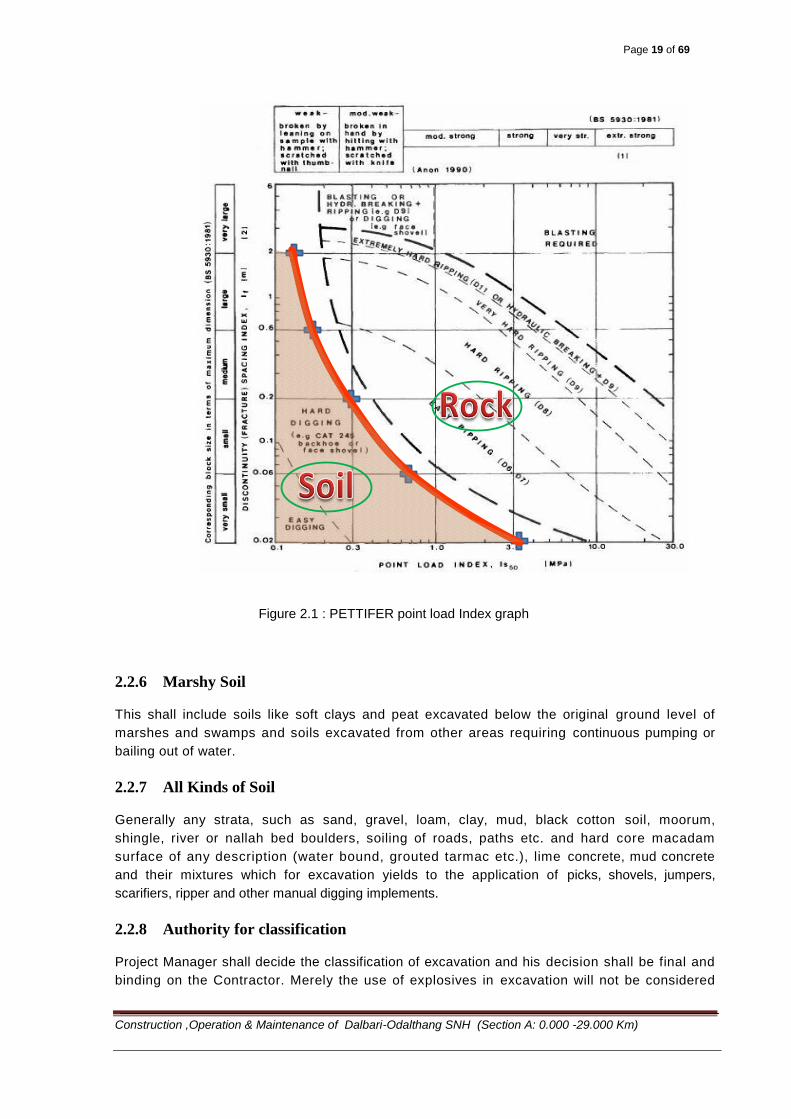
The PETTIFER point load index graph as per BS:5930 shall be used to classify the material type (soil
or rock) in case of any misunderstanding and or disputes between the contractor and the Project
Manager in the classification of soil.
The classification requires testing of the rock lumps of 5 representative samples in the laboratory
using point load test apparatus to obtain point load Index (IC50). The discontinuity spacing index (Ii)
shall be noted jointly by the contractor and the Project Manager. Using these two parameters the ‘soil’
or ‘rock’ type shall be classified. All easy to moderately hard digging shall be classified as soil and
easy ripping to material requiring use of rock breaker or controlled blasting shall be classified as
‘rock’.
Page 19 of 69
Construction ,Operation & Maintenance of Dalbari-Odalthang SNH (Section A: 0.000 -29.000 Km)
Figure 2.1 : PETTIFER point load Index graph
2.2.6 Marshy Soil
This shall include soils like soft clays and peat excavated below the original ground level of
marshes and swamps and soils excavated from other areas requiring continuous pumping or
bailing out of water.
2.2.7 All Kinds of Soil
Generally any strata, such as sand, gravel, loam, clay, mud, black cotton soil, moorum,
shingle, river or nallah bed boulders, soiling of roads, paths etc. and hard core macadam
surface of any description (water bound, grouted tarmac etc.), lime concrete, mud concrete
and their mixtures which for excavation yields to the application of picks, shovels, jumpers,
scarifiers, ripper and other manual digging implements.
2.2.8 Authority for classification
Project Manager shall decide the classification of excavation and his decision shall be final and
binding on the Contractor. Merely the use of explosives in excavation will not be considered
Page 20 of 69
Construction ,Operation & Maintenance of Dalbari-Odalthang SNH (Section A: 0.000 -29.000 Km)
as a reason for higher classification unless blasting is clearly necessary in the opinion of the
Project Manager.
2.3 Excavation
All excavations shall be carried out in conformity with the directions laid herein-under and
in a manner approved by the Project Manager. The works shall be so done that the suitable
materials available from excavation are satisfactorily utilized as decided upon beforehand.
While planning of excavations, the Contractor shall take all adequate precautions against soil
erosion, water pollution etc. and take appropriate drainage measures to keep the sites free of
water.
The excavations shall conform to the lines, grades, side slopes and levels shown on the
drawings or as directed by the Project Manager. The Contractor shall not excavate outside
the limits of excavation. Subject to the permitted tolerances, any excess depth/ width
excavated beyond the specified levels/dimensions on the drawings shall be made good at the
cost of the Contractor with the suitable material of characteristics similar to that removed
and compacted.
All debris and loose materials on the slopes of cutting shall be removed. No backfilling shall be
allowed to obtain required slopes excepting that when boulders or soft materials are encountered
in the cut slopes, these shall be excavated to approved depth on instructions of the Project
Manager and the resulting cavities filled with suitable materials and thoroughly compacted in
an approved manner.
After excavation, the sides of the excavated areas shall be trimmed and the area contoured to
minimize erosion and ponding, allowed for natural drainage to take place. If trees were removed,
new trees shall be planted, as directed by the Project Manager. The cost of planting new trees
shall be deemed to be incidental to the work.
2.3.1 Setting out
After the site has been cleared, the limits of excavation shall be set out true to lines, curves,
slopes, grades and sections as shown on the drawings or as directed by the Project Manager. The
Contractor shall provide all labour, survey instruments and materials such as strings, pegs, nails,
bamboos, stones, lime, mortar, concrete, etc., required in connection with the setting out of
works and the establishments of bench marks. The Contractor shall be responsible for the
maintenance of the benchmarks and other marks and stakes as long as in the opinion of the
Project Manager, they are required for the work.
The ground levels shall be taken at 5m to 15m intervals in uniformly sloping ground and at closer
intervals where local mounds, pits or undulations are met with. The ground levels shall be
recorded in field books and plotted on plans. Plans shall be drawn to a suitable scale and North
direction and position of benchmark shall be shown on the plans. The contractor and the
Project Manager shall sign the plan before the earthwork is started. The contractor at his own
cost shall supply the labour required for taking levels.
2.3.2 Stripping and storing topsoil
When so directed by the Project Manager, the topsoil existing over the sites of excavation
shall be stripped to specify depths and stockpiled at designated locations for re-use in
Page 21 of 69
Construction ,Operation & Maintenance of Dalbari-Odalthang SNH (Section A: 0.000 -29.000 Km)
covering embankment slopes, cut slopes, and other disturbed areas where re -vegetation is
desired. Prior to stripping the topsoil, all trees, shrubs etc. shall be removed along with their roots,
with the approval of the Project Manager.
2.3.3 Methods, tools and equipment
Only such methods, tools and equipment as approved by the Project Manager shall be
adopted/used in the work. If so desired by the Project Manager, the Contractor shall
demonstrate the efficacy of the type of equipment to be used before the commencement of the work.
Methods, tools and equipment to be adopted for the work shall be such which will not affect the
property to be preserved
2.3.4 Rocks excavation
Rocks, when encountered in the road excavation, shall be removed up to the formation level or
as otherwise indicated on the drawings. Where, however, unstable shale or other unsuitable
materials are encountered at the formation level, these shall be excavated to the extent of 500
mm below the formation level or as otherwise specified. In all cases, the excavation operations
shall be so carried out that at no point on cut formation the rock protrudes above the specified
levels. rocks and large boulders which are likely to cause differential settlement and also local
drainage problems should be removed to the extent of 500 mm below the formation level in full
formation width including drains and cut through the side drains.
Slopes in rock cutting shall be uniform lines corresponding to slope lines shown on the
drawings or as directed by the Project Manager. Notwithstanding the foregoing, all loose pieces
of rock on excavated slope surface, which move when pierced by a crowbar, shall be removed.
Where blasting is to be resorted to, the same shall be carried out as per the RGOB blasting
manual and all precautions indicated therein observed.
2.3.5 Marsh excavation
The excavation of soils from marshes/swamps shall be carried out as per the programme
approved by the Project Manager. Excavation of marshes shall begin at one end and proceed in
one direction across the entire marsh immediately ahead of back filling. The method and
sequence of excavating and back filling shall be such as to ensure, to the extent practicable, the
complete removal or displacement of all muck from within the lateral limits called for on the
drawings or as staked by the Project Manager, and to the bottom of the marsh, firm support
or levels indicated.
2.3.6 Blasting
The contractor shall obtain a licence from the competent authority for obtaining and storing the
explosives. The contractor shall procure the explosives, fuses, detonators etc. from the Government
or as per the provision in terms and condition of the contract. The Project Manager or his
representative shall have the right to check the contractor's store and accounts of explosives.
The contractor shall provide facilities for this.
All blasting work shall only be done under careful supervision of trained personnel and the
contractor shall take all precautions as per rules for blasting operations.
Page 22 of 69
Construction ,Operation & Maintenance of Dalbari-Odalthang SNH (Section A: 0.000 -29.000 Km)
The contractor shall be responsible for any damage arising out of accident to the workmen,
public or property due to storage, transportation and use of explosive during blasting
operations.
2.3.7 Cutting
In firm soil, the sides of the trench shall be kept vertical up to a depth of 2m from the bottom. For a
greater depth, the excavation profiles shall be widened by allowing steps of 500mm on either side
after every 2m from the bottom. Alternatively the excavation can be done so as to give slopes of
1:4.
Where the soil is soft, loose or slushy, the width of steps shall be suitably increased or side
sloped or the soil shored up as directed by Project Manager. It shall be the responsibility of the
contractor to take complete instructions in writing from Project Manager regarding the
stepping, sloping or shoring to be done for excavation deeper than 2 metres.
The bed of excavation shall be made to the correct level or slope and consolidated by watering
and ramming. Soft/defective spots shall be dug out and filled with levelling concrete as directed
by the Project Manager. The excess depth shall be made good by the contractor at his own cost
with the concrete of the same mix as levelling concrete.
Where hard rock is met with and blasting operations are considered necessary, the contractor
shall obtain the approval of the Project Manager. For an ordinary rock, in general, the
blasting operation is not adopted but if the contractor wishes to resort to blasting, he can do so,
with the permission of the Project Manager but nothing extra shall be paid for this blasting
2.3.8 Disposal of Excavated Material
Excavated material classified as suitable by the Project Manager shall generally be utilized as backfill
or embankment fill. Surplus suitable material shall be stockpiled at the Site. Excavated suitable
material for use as backfill shall be deposited by the Contractor in spoil heaps at points convenient for
re-handling of the material during the backfilling operation and approved by the Project Manager.
Excavated material classified as unsuitable as backfill by the Project Manager shall be carried to
waste.
Excavated material shall be deposited in such places and in such a manner as not to cause damage
to roads, services or property either within or outside the right-of-way and so as to cause no
impediment to the drainage of the site or surrounding area. The location of spoil heaps shall be
subject to the approval of the Project Manager who may require that the reference lines and the
traverse lines of any part of the structure be kept free of obstruction.
2.3.9 Pumping and Bailing
Pumping and bailing from the interior of any foundation enclosure shall be done in such a manner as
to preclude the possibility of the movement of water through or alongside any concrete being placed.
No pumping or bailing will be permitted during the placing of concrete and for a period of at least 24
hours thereafter unless it is done from a suitable pump separated from the concrete work by a
watertight wall or from well points.
Excavations shall be as dry as possible prior to and during placing concrete. Placing concrete under
water will only be permitted if indicated on the Drawings or approved by the Project Manager.

Page 23 of 69
Construction ,Operation & Maintenance of Dalbari-Odalthang SNH (Section A: 0.000 -29.000 Km)
2.3.10 Foundation Fill Material
Material for foundation fill shall be a natural or artificial mixture of sand or other mineral aggregate,
free from vegetable matter, soft particles and excess clay and shall consist of suitably graded sand to
one of the grading envelopes A to C of Table 2.3, gravel or stone as shown on the Drawings or as
required by the Project Manager, or concrete. Concrete for foundation fill shall conform to the general
requirements of Section 3.1. Concrete to be placed under water shall conform to the requirements of
Section 3.4.13. Concrete used as foundation fill in dry excavation shall be M15.
Table 2.3 Grading of foundation fill material
A B C D E
Nominal
fineness
modulus
Not less
than 2.8
1.5-2.8 1.0-1.5 0.8-1.0 0.5-0.8
Sieve size
(mm)
% passing by weight
10 100 100 100 100 100
5.0 90-95 95-100 100 100 100
2.4 70-90 90-100 100 100 100
1.2 45-70 70-95 95-100 100 100
0.6 25-45 40-80 85-100 95-100 100
0.3 10-20 10-50 50-80 70-90 80-95
0.15 0-2 0-20 5-25 15-40 30-60
Grading outside the above limits may in certain circumstances be approved by the Project Manager.
Such permission shall be in writing.
2.3.11 Backfill Material
The excavated materials shall be used for backfilling if found suitable and approved by the Project
Manager. The source (borrow pit) and type of fill material have to be approved by the Project
Manager.
The earth shall be free from all roots, grass and rubbish. All lumps and clods exceeding 80mm in any
direction shall be broken and each layer shall be consolidated by ramming and rolling, etc. Watering
shall be done, if so stipulated. The top surface of the finally finished area shall be neatly dressed.
The finished formation levels, in case of filling shall be kept higher than the required levels, by making
an allowance of 10% of depth of filling for future settlement in case of ordinary consolidated fills, and
5% in case where consolidation is done by heavy mechanical machinery under optimum moisture
conditions.
2.3.12 Backfilling
All spaces excavated under these Specifications and not occupied by the permanent structure shall
be backfilled. However, the finished level of the back fill shall be as per the lines and levels of the
finished profile of the slope shown in the design drawings. Backfilled material shall fully comply with
this Specification and adequate provision shall be made for drainage. No backfilling shall commence
until permission has been given by the Project Manager.
Page 24 of 69
Construction ,Operation & Maintenance of Dalbari-Odalthang SNH (Section A: 0.000 -29.000 Km)
Backfilling shall be well compacted and shall be done in layers, not exceeding 200mm in each layer.
Each layer shall be watered, rammed and consolidated before the succeeding one is laid.
Special care shall be taken to prevent any unduly high pressure against the structures. In placing
backfill and embankment, the material shall be placed insofar as possible to approximately the same
height on both sides of the structure at the same time. If conditions require backfilling appreciably
higher on one side, the additional material on the higher side shall not be placed until permission is
given by the Project Manager that the structure has enough strength to withstand any pressure
created.
2.4 Measurements and Payments
The volume of excavation shall be measured in cubic meters of excavated undisturbed material.
The quantity of excavation for structures to be measured for payment shall include excavation for all
structures. The measured volume shall be the excavation plan outline, bounded on the bottom by the
plane of the underside of the blinding concrete under the reinforced concrete footing and on the top by
the surface of the existing ground and on the sides by vertical planes of the footings and the volume
so measured shall be term as “Solid Volume”.
Additional excavations for slope cutting, working space and for other purposes of construction ease
and convenience shall not be paid extra. The cost for such additional excavation works is deemed to
be included in the unit rates under the payable items and quantities of the excavation works. The
removal of slides, cave-ins, silting or filling shall also neither be measured nor paid for.
The soil/rock excavation for construction/widening of approach roads to the bridge however shall be
measured as actual volume of excavation as per the drawings or as directed by the Project Manager
as per the actual requirement of the site. The contractor has to do a detail survey of the area to be
excavated as per direction of the Project Manager prior to and after the excavation to arrive at the
actual volume of excavation. The measured volume shall be in-situ volume and no allowance shall be
allowed for bulking and other forms of volume change.
The measured volume for backfilling and filling behind the abutment/return walls etc. shall be the
backfilling plan outline bounded at the bottom by the plane of the underside of the blinding concrete
under the reinforced concrete footing and on the top by the surface of the finished ground and on the
sides by vertical planes of the footings minus the volume occupied by the permanent structure.
However the areas around the foundations excavated by the contractor for creating working space,
stabilizing excavation slope etc. shall be backfilled to required degree of compaction as per this
specification at the contractor’s own cost.
The length, breadth and depth/height shall be measured correct to 10mm. In case the measurements
are taken with staff and level, the level shall be recorded correct to 5mm and depth of cutting and
heights of filling calculated correct to 5mm. The cubical contents shall be worked out to the nearest
two places of decimal in cubic metres.
The rates shall cover the cost for carrying out all the required operations including cost of labour,
materials, equipment hired/owned, tools and plants, and incidentals necessary to complete the work.
In case of rock, the rate shall also include the cost of all operations of blasting with explosive and
accessories as mentioned above. The excavation of Bridge foundation shall be paid in cum as per
BoQ item No 14.A.2
Page 25 of 69
Construction ,Operation & Maintenance of Dalbari-Odalthang SNH (Section A: 0.000 -29.000 Km)
3.0 SECTION 3: STRUCTURRES
3.1 Concrete for structures
3.1.1 Standards
The concrete materials, production, methods, testing & admixtures shall conform to the latest
revisions of the following Indian Standards or, where not covered by these standards, to the
equivalent International Standards:
IS: 8112 43 grade Ordinary Portland Cement.
IS: 12269 53 grade Ordinary Portland Cement.
IS: 383 Coarse & fine aggregates from natural sources for aggregates.
IS: 456 Code of practice for plain & reinforced concrete.
IS: 457 Code of practice for general construction of plain & reinforced concrete for dams &
other massive structures.
IS: 516 Method of test for strength of concrete.
IS: 1199 Methods of sampling & analysis of concrete.
IS: 1489 Portland Pozzolana cement.
IS: 2386 Methods of test for aggregates for concrete.
IS: 2505 Concrete vibrators – immersion type – general.
IS: 2506 General requirements for screed board concrete vibrators.
IS: 4082 Stacking & storage of construction materials & components at site– recommendations.
IS: 7861 Code of practice for extreme weather concreting.
IS: 9103 Admixtures for concrete.
IS: 10262 Recommended guidelines for concrete mix design.
IRC: 112 Code o Practice for Concrete Road Bridges
In cases of conflict between or among the above standards & the specifications given herein, the
decision of the Client shall prevail.
3.2 Description
This work shall consist of the construction of all or portions of concrete structures, of the required
grades and types, with or without reinforcement and with or without admixture, in accordance with
these Specifications and to the lines, levels, grades and dimensions shown on the Drawings and as
required by the Project Manager.
The cement concrete shall consist of a mixture of cement, water and coarse and fine aggregate with
or without admixture.
3.3 Materials
3.3.1 Specifications for Materials
A) Cement
Cement shall conform to the requirements of Indian Standard as mentioned in Article 3.1.1 of this
specification unless other types are indicated on the Drawings or specified by the Project Manager.
One of the types of the cements, specified below shall be used.
a) Ordinary Portland cement conforming to IS: 269
b) Portland blast furnace slag cement conforming to IS: 455

Page 26 of 69
Construction ,Operation & Maintenance of Dalbari-Odalthang SNH (Section A: 0.000 -29.000 Km)
e) Portland pozzolana cement conforming to IS: 1489
Bagged or bulk cement which has partially set or which contains lumps of caked cement shall be
rejected. The use of cement reclaimed from discarded or used bags shall not be permitted.
B) Water
Water used for mixing mortars and concrete shall be clean and reasonably free from injurious
quantities of deleterious materials such as oils, acids, alkalis, salts and vegetable growth. Generally
potable water shall be used. Where water can be shown to contain any sugar or an excess of acid,
alkali or salt, the Project Manager may refuse to permit its use. As a guide, the following
concentrations may be taken to represent the maximum permissible limits of deleterious materials in
water.
(a) Limits of acidity: - To neutralize 200 ml sample of water, it should not require more than 2 ml of 0.1
N caustic soda solutions.
(b) Limits of Alkalinity: - To neutralize 200 ml sample of water it should not require more than 0.1 ml of
0.1 N hydrochloric acid.
(c) Percentage of solids should not exceed: -
Organic 200 ppm (0.02%)
Inorganic 3000 ppm (0.30%)
Sulphates 500 ppm (0.05%)
Alkali chlorides 1000 ppm (0.1%)
Water found satisfactory for mixing is suitable for curing concrete. However, the water used for curing
should not produce any objectionable stain or deposit on the concrete surface.
The use of river water will be subject to the approval of the Project Manager. Such approvals may be
withdrawn from time to time depending on the condition of the river.
C) Admixtures
Admixtures or any other additions shall not be used except with the written approval of the Project
Manager.
Admixtures, if specified or permitted, shall fully conform to the requirements of Indian Standard IS:
9103
D) Coarse Aggregate
Coarse aggregate for all types of concrete with the exception of blinding concrete shall consist of hard
durable crushed or broken rock and generally conform to the requirements of Indian Standard IS: 383
(or AASHTO Standard Specification M 80 or ASTM C33 / C33M – 08). Coarse aggregate shall be
clean, free from dust and other deleterious material.
The amounts of deleterious substances shall not exceed the following limits:
1) Soft fragments; 2% by mass
2) Clay lumps; 0.25% by mass
Page 27 of 69
Construction ,Operation & Maintenance of Dalbari-Odalthang SNH (Section A: 0.000 -29.000 Km)
3) Material Passing the 0.075 mm sieve; 0.50% by mass if clay, 1.50% by mass if fractures dust
In addition, coarse aggregates shall comply with the following:
1) Thin or elongated pieces; Flakiness Index less than 30
2) The aggregate crushing value shall be less than 30% and the ten percent fines value shall be
greater than 150 kN.
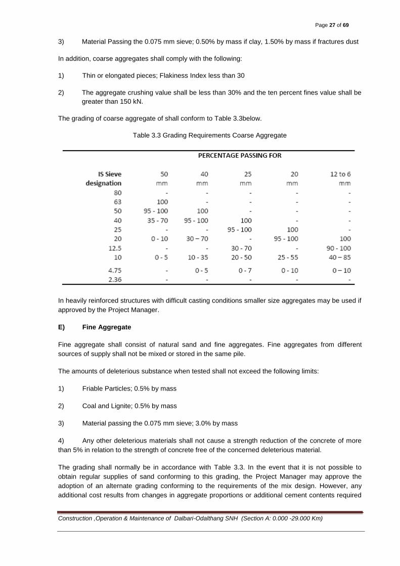
The grading of coarse aggregate of shall conform to Table 3.3below.
Table 3.3 Grading Requirements Coarse Aggregate
In heavily reinforced structures with difficult casting conditions smaller size aggregates may be used if
approved by the Project Manager.
E) Fine Aggregate
Fine aggregate shall consist of natural sand and fine aggregates. Fine aggregates from different
sources of supply shall not be mixed or stored in the same pile.
The amounts of deleterious substance when tested shall not exceed the following limits:
1) Friable Particles; 0.5% by mass
2) Coal and Lignite; 0.5% by mass
3) Material passing the 0.075 mm sieve; 3.0% by mass
4) Any other deleterious materials shall not cause a strength reduction of the concrete of more
than 5% in relation to the strength of concrete free of the concerned deleterious material.
The grading shall normally be in accordance with Table 3.3. In the event that it is not possible to
obtain regular supplies of sand conforming to this grading, the Project Manager may approve the
adoption of an alternate grading conforming to the requirements of the mix design. However, any
additional cost results from changes in aggregate proportions or additional cement contents required
Page 28 of 69
Construction ,Operation & Maintenance of Dalbari-Odalthang SNH (Section A: 0.000 -29.000 Km)
to achieve the specified strengths, when using these alternative grading, shall be borne by the
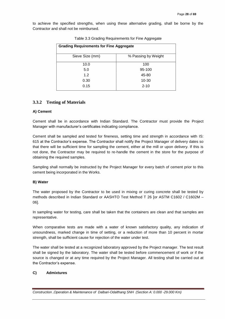
Contractor and shall not be reimbursed.
Table 3.3 Grading Requirements for Fine Aggregate
Grading Requirements for Fine Aggregate
Sieve Size (mm) % Passing by Weight
10.0 100
5.0 95-100
1.2 45-80
0.30 10-30
0.15 2-10
3.3.2 Testing of Materials
A) Cement
Cement shall be in accordance with Indian Standard. The Contractor must provide the Project
Manager with manufacturer’s certificates indicating compliance.
Cement shall be sampled and tested for fineness, setting time and strength in accordance with IS:
615 at the Contractor’s expense. The Contractor shall notify the Project Manager of delivery dates so
that there will be sufficient time for sampling the cement, either at the mill or upon delivery. If this is
not done, the Contractor may be required to re-handle the cement in the store for the purpose of
obtaining the required samples.
Sampling shall normally be instructed by the Project Manager for every batch of cement prior to this
cement being incorporated in the Works.
B) Water
The water proposed by the Contractor to be used in mixing or curing concrete shall be tested by
methods described in Indian Standard or AASHTO Test Method T 26 [or ASTM C1602 / C1602M –
06].
In sampling water for testing, care shall be taken that the containers are clean and that samples are
representative.
When comparative tests are made with a water of known satisfactory quality, any indication of
unsoundness, marked change in time of setting, or a reduction of more than 10 percent in mortar
strength, shall be sufficient cause for rejection of the water under test.
The water shall be tested at a recognized laboratory approved by the Project manager. The test result
shall be signed by the laboratory. The water shall be tested before commencement of work or if the
source is changed or at any time required by the Project Manager. All testing shall be carried out at
the Contractor’s expense.
C) Admixtures
Page 29 of 69
Construction ,Operation & Maintenance of Dalbari-Odalthang SNH (Section A: 0.000 -29.000 Km)
Chemical admixtures are not to be used until permitted by the Project manager. In case their use is
permitted, the type, amount and method of use of any admixtures proposed by the Contractor shall be
submitted to the Project Manager for approval. The minimum cement specified shall not be reduced
on account of the use of the admixtures.
The contractor shall provide the following information concerning each admixture to the Project
Manager:
a. Normal chemical dosage and detrimental effects if any of under dosage and over dosage.
b. The chemical names of the main ingredients in the admixtures.
c. The chloride content, if any, expressed as a percentage by weight of admixture.
d. Whether or not the admixture leads to the entrainment of air when used in the manufacturer’s
recommended dosage.
e. Where two or more admixtures are proposed to be used in any one mix, the manufacturer’s
written confirmation of their compatibility.
3. In reinforced concrete, the chloride content of any admixture used shall not exceed 2 percent
by weight of the admixtures as determined in accordance with IS: 6925 and the total chloride
and sulphate contents in concrete mix shall not exceed 1.15 and 4.0 percent respectively by
weight of cement.
The admixtures when used shall conform to IS: 9103. The suitability of all admixtures shall be verified
by trial mixes.
The addition of calcium chloride to concrete containing embedded metal will not be permitted under
any circumstances.
Retarding admixtures when used shall be based on ligno-sulphonates with due consideration to
clause 5.2 and 5.3 of IS: 7861
D) Aggregates
1) Selection and Approval
From the aggregate materials proposed by the Contractor, samples shall be selected according to
Standard Testing Procedure and in the presence of the Project Manager. The samples shall be tested
at the site laboratory or at an approved testing laboratory for conformance with Section 3.3.1 of these
Specifications.
2) Quality Control
The quality control of the aggregate shall be as directed by Project Manager. Grading shall be
checked at regular intervals for each supply.
Moisture contents of fine aggregate shall be determined at any time when a change in moisture
content is expected.
If the Contractor proposes to change the source of aggregate, the Project Manager shall be informed
in advance and in no case less than 3 weeks before the new aggregate shall be used.
3.3.3 Composition of Concrete
A) Classes of Concrete
Page 30 of 69
Construction ,Operation & Maintenance of Dalbari-Odalthang SNH (Section A: 0.000 -29.000 Km)
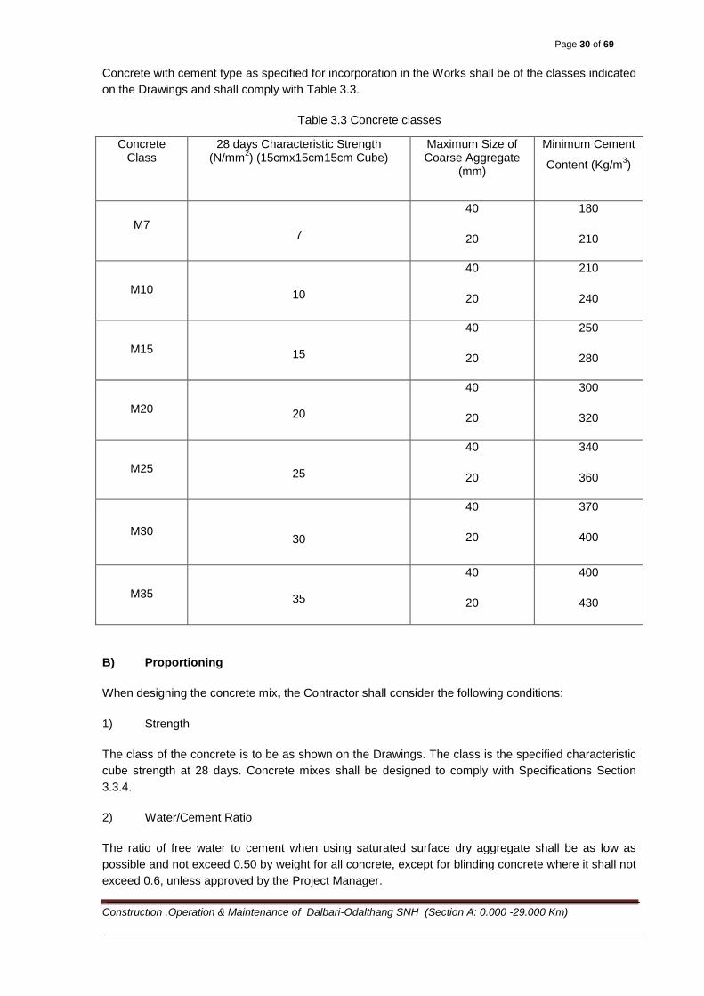
Concrete with cement type as specified for incorporation in the Works shall be of the classes indicated
on the Drawings and shall comply with Table 3.3.
Table 3.3 Concrete classes
Concrete Class
28 days Characteristic Strength (N/mm
2) (15cmx15cm15cm Cube)
Maximum Size of Coarse Aggregate
(mm)
Minimum Cement
Content (Kg/m3)
M7 7
40
20
180
210
M10 10
40
20
210
240
M15 15
40
20
250
280
M20 20
40
20
300
320
M25 25
40
20
340
360
M30 30
40
20
370
400
M35 35
40
20
400
430
B) Proportioning
When designing the concrete mix, the Contractor shall consider the following conditions:
1) Strength
The class of the concrete is to be as shown on the Drawings. The class is the specified characteristic
cube strength at 28 days. Concrete mixes shall be designed to comply with Specifications Section
3.3.4.
2) Water/Cement Ratio
The ratio of free water to cement when using saturated surface dry aggregate shall be as low as
possible and not exceed 0.50 by weight for all concrete, except for blinding concrete where it shall not
exceed 0.6, unless approved by the Project Manager.
Page 31 of 69
Construction ,Operation & Maintenance of Dalbari-Odalthang SNH (Section A: 0.000 -29.000 Km)
For concrete in barriers, edge beams and bridge decks directly exposed to traffic or concrete in pile
caps or abutments in contact with the ground, the water cement ratio shall not exceed 0.45, unless
approved by the Project Manager.
3) Minimum Cement Content
As indicated for the respective class in Table 3.3
4) Minimum Filler Content
Filler content (fine aggregate less than 0.25 mm and cement) shall not be less than as follows (except
for mass concrete).
Maximum coarse aggregate size (mm) 20 40
Minimum filler content (kg/m3 of concrete) 435 350
5) Coarse Aggregate
The maximum size of coarse aggregate will generally be stated on the Drawings; either 40 mm or 20
mm, in accordance with Table 3.3. Grading and quality is to comply with the requirements of Section
3.3.1.
6) Fine Aggregate
The grading and quality is to comply with the requirements of Section 3.3.1.
7) Workability
The concrete shall be of suitable workability to obtain full compaction. Slumps measured in
accordance with approved standard procedure shall not exceed 75 mm unless otherwise indicated on
the Drawings or approved by the Project Manager.
C) Trial Mixes
After the Contractor has received approval for the cement and aggregate to be used, he shall prepare
trial mixes with concrete of designed proportions to prove and establish workability, strength, water
cement/ratio, surface criteria etc. Methods of transporting fresh concrete and the compaction
equipment shall be considered. The trial mixes shall be made and compacted in the presence of the
Project Manager, using the same type of plant and equipment as will be used for the Works.
From each trial mix, cylinders or cubes shall be made and tested in accordance with Section 3.3.4.
From the same mix as that from which the test specimens are made, the workability of the concrete
shall be determined by the slump test. The remainder of the mix shall be cast in a wooden mould and
compacted. After 24 hours the sides of the mould shall be struck and the surface examined in order to
satisfy the Project Manager that an acceptable surface can be obtained with the mix.
The trial mix proportions should be approved if the required strength is obtained from tests carried out
in accordance with Section 3.3.4 and the consistency and surface is to the satisfaction of the Project
Manager.

Page 32 of 69
Construction ,Operation & Maintenance of Dalbari-Odalthang SNH (Section A: 0.000 -29.000 Km)
When a mix has been approved, no variations shall be made in the mix proportions, or in the type,
size, grading zone or source, of any of the constituents without the consent of the Project Manager,
who may require further trial mixes to be made before any such variations are approved.
Until the results of trial mixes for a particular class have been approved by the Project Manager, no
concrete of the relevant class shall be placed in the Works.
When the Contractor intends to purchase factory-made precast concrete units, trial mixes may be
dispensed with provided that evidence is given to satisfy the Project Manager that the factory regularly
produces concrete which complies with the Specifications. The evidence shall include details of mix
proportions, water/cement ratios, slump tests and strengths obtained at 28 days.
3.3.4 Control of Concrete Quality
A) General
The Contractor shall assume the full responsibility for the quality of the concrete conforming to these
Specifications and this responsibility shall not be relieved by the testing carried out and approved by
the Project Manager.
The Contractor shall thus at his own discretion establish additional testing procedures as necessary.
B) Control of Concrete Production
1) Materials
Materials used shall be tested in accordance with the relevant sections of this specification.
2) Plant and Equipment
Batching plants will be tested by the Contractor in a manner approved by the Project Manager before
any major concrete casting and at any other time if requested by the Project Manager. The concreting
plant and equipment shall have a capacity for atleast 80m3 of concreting per day.
3) Fresh Concrete
The frequency of slump tests shall be as directed by the project Manager, with at least one test per 25
m3 of concrete.
C) Control of Strength
C.1) Sampling and Testing
The Contractor shall take samples of the concrete for testing. The number, frequency and location
shall be decided by the Project manager. A minimum of 3 concrete cubes should be taken for each
day’s casting, or for every 15 m3
of concrete cast in large pours. The slump of concrete samples shall
be measured.
The procedures for sampling and making cubes and testing them shall be as described in IS: 1199/IS:
516 (or ASTM C873 / C873M - 04e1.)
C.2) Strength Requirement
Page 33 of 69
Construction ,Operation & Maintenance of Dalbari-Odalthang SNH (Section A: 0.000 -29.000 Km)
The results of the testing shall conform to the strength requirements according to IS: 456 or to any
mathematically correct statistical test for each casting section.
C.2.1) General
The characteristic strength of concrete is the 28 days strength below which not more than 5% of the
test results may be expected to fall.
C.2.2) Target Mean Strength
The concrete mix should be designed to have a mean strength greater than the required characteristic
strength by at least the current margin.
The current margin for each particular type of concrete mix shall be determined; it may be taken as
having the smaller of the values given by (1) or (2) below.
C.2.2.1)1.64 times the standard deviation of tests on at least 100 separate batches of concrete of
nominally similar proportions of similar materials and produced over a period not exceeding 12
months by the same plant under similar supervision.
C.2.2.2)1.64 times the standard deviation of tests on at least 40 separate batches of concrete of
nominally similar proportions of similar materials and produced over a period exceeding 5 days but
not exceeding 6 months by the same plant under similar supervision.
Where there are insufficient data to satisfy (1) or (2) above, the margin for the initial mix design should
be taken as one-thirds of the characteristic strength for concrete. This margin should be used as the
current margin only until sufficient data are available to satisfy (1) or (2) above. However, when the
required characteristic strength approaches the maximum possible strength of concrete made with a
particular aggregate, a smaller margin may be permitted by the Project Manager for the initial mix
design.
C.2.3) Testing Plan
Each cube shall be made from a single sample taken from randomly selected batches of concrete.
Compliance with the specified characteristic strength may be assumed if:
1) The average strength determined from any group of four consecutive test cubes exceeds the
specified characteristic strength by not less than 0.5 times the current margin, and
2) Each individual test result is greater than 85% of the specified characteristic strength.
The current margin should be taken to be one-thirds (1/3) of the specified characteristic strength for
concrete, unless as mentioned above a smaller margin has been established to the satisfaction of the
Project Manager.
If only one cube result fails to meet the second requirement then that result may be considered to
represent only the particular batch of concrete from which that cube was taken provided the average
strength of the group satisfies the first requirement.
If more than one cube in a group fails to meet the second requirement or if the average strength of
any group of four consecutive test cubes fail to meet the first requirement then all the concrete in all
the batches represented by all such cylinders shall be deemed not to comply with the strength
Page 34 of 69
Construction ,Operation & Maintenance of Dalbari-Odalthang SNH (Section A: 0.000 -29.000 Km)
requirements. For the purposes of this sub-Section, the batches of concrete represented by a group of
four consecutive test cylinder/cubes shall include the batches from which samples were taken to
make the first and the last cubes in the group of four, together with all the intervening batches.
C.2.4) Action to be taken in the event of Non-Compliance with the Testing Plan
When the average strength of four consecutive test cubes fail to meet the first requirement in (F),
above, the mix proportions of subsequent batches of concrete should be modified to increase the
strength.
The action to be taken in respect of the concrete which is represented by the test- cubes which fail to
meet either of the requirements (or not by correct statistical proof can be verified to have the required
strength) shall be determined by the Project Manager. This may range from qualified acceptance in
less severe cases, to rejection and removal in the most severe cases.
The Project Manager may also require the Contractor at his own expenses to prove statistically the
strength, by boring out cores and testing them according to a program approved by the Project
Manager. The age of the concrete and degree of hardening at the time of the new testing shall be
considered. The equivalent cylinder/cube strength shall comply the minimum characteristic strength or
as decided by the Project Manager.
D) Control of Hardening
If the Contractor wants to remove forms and scaffolding earlier than specified herein, extra test
specimens shall be cast by the Contractor in accordance with the instruction of the Project Manager.
These specimens shall be tested the day before removal of the form. On the basis of the test results
the Project Manager shall take the final decision on the time for the removal of forms.
3.4 Construction Methods
3.4.1 General
The Contractor shall in due time and as soon as possible present and discuss his construction
methods and work program with the Project Manager and shall obtain his approval before
commencement of any work.
The Contractor shall maintain an adequate number of trained and experienced supervisors and
foremen at the Site to supervise and control the work.
All construction, other than concrete, shall conform to the requirements prescribed in other Sections of
the Specifications, for the particular items of work comprising the complete structure.
3.4.2 Care and Storage of Concrete Materials
A) Storage of Cement
All cement shall be stored in suitable weatherproof buildings or silos which will protect the cement
from dampness. These buildings or silos shall be placed in locations approved by the Project
manager. Provisions for storage shall be ample, and the shipments of cement as received shall be
separately stored in such manner as to provide easy access for the identification and inspection of
each shipment. Storage buildings shall have a capacity for the storage of a sufficient quantity of
cement to allow sampling at least 14 days before the cement is to be used. Cement shall meet the
Page 35 of 69
Construction ,Operation & Maintenance of Dalbari-Odalthang SNH (Section A: 0.000 -29.000 Km)
test requirements at any time and any cement stored for an elongated time shall be checked and
tested before use regardless of whether it has previously been tested.
B) Storage of Aggregates
Aggregates shall be so stored as to prevent the inclusion of foreign material. Aggregates shall not be
placed upon the finished roadbed. Aggregates of different sizes and kinds shall be placed in different
stockpiles. Stockpiles of blended coarse aggregates shall be built up in successive horizontal layers
not more than 1 meter thick. Each layer shall be completed before the next is started. Should
segregation occur, the aggregates shall be recombined to conform to the grading requirement.
Washed aggregates and aggregates produced or manipulated by methods which involve the use of
water shall be allowed to drain at least 12 hours before use.
3.4.3 Preparations before Casting
Before any major casting, the Contractor shall prepare a complete “casting program” describing staff
and labor, consumption of materials, plant, tools and equipment, reserves of materials, standby plant
and equipment, proposed means of handling and placing the concrete, quality controls etc.
No concrete shall be mixed and placed until the Contractor’s casting program has been approved in
writing by the Project Manager.
Equipment and tools necessary for handling materials and performing the work, and satisfactory to
the Project Manager as to design, capacity, and mechanical condition, shall be at the site of the work
before casting is started.
If any equipment is not maintained in full working order, or if the equipment as used by the Contractor
proves inadequate to obtain the result prescribed, such equipment shall be repaired or other suitable
equipment substituted or added at the discretion of the Project manager.
3.4.4 Measuring Materials
All material in the mix shall be proportioned by weight or volume, subject to the approval of the Project
manager.
When volume batching is proposed by the Contractor, the exact proportions must be converted from
trial mix weights to volumes, from bulk densities determined in the laboratory. Written approval from
the Project Manager is required.
3.4.5 Mixing Concrete
A) General
All concrete shall be mixed in batch mixers, either at the site of construction, at a central plant, or in
transit. Each mixer shall have attached to it in a prominent place, a manufacturer’s plate showing the
capacity of the drum in terms of mixed concrete and the speed of rotation of the mixing drum.
B) Mixers at Local Site of Construction
Mixers at local sites shall be approved drum-type capable of combining the aggregate, cement, and
water into a thoroughly mixed and uniform mass within the specified mixing period and of discharging
the mixture without segregation. The mixer shall be equipped with a suitable charging hopper, water
Page 36 of 69
Construction ,Operation & Maintenance of Dalbari-Odalthang SNH (Section A: 0.000 -29.000 Km)
storage and a water measuring device, accurate within 1%. Controls shall be so arranged that the
water can be applied only while the mixer is being charged. Suitable equipment for discharging the
concrete shall be provided. The mixer shall be cleaned at suitable intervals. The pickup and throw-
over blades in the drum shall be replaced when they have lost 10% of their depth.
The mixer shall be operated at a drum speed of between 15 and 20 revolutions per minute. The
batched materials shall be so charged into the drum that a portion of the water shall enter in advance
of the cement and aggregates and the water shall continue to flow into the drum for a minimum time
of 5 seconds after all the cement and aggregates are in the drum. Mixing time shall be measured from
the time all materials except water are in the drum and shall, in the case of mixers having a capacity
of 1 cubic Meter or less, not be less than 50 seconds nor more than 70 seconds. In the case of dual
drum mixers, the mixing time shall not include transfer time. The contents of an individual mixer drum
shall be removed before a succeeding batch is emptied therein. Any concrete mixed less than the
specified minimum time shall be discarded and disposed of by the Contractor at his own expense.
The volume of concrete mixed per batch shall not exceed the mixer’s nominal capacity in cubic feet or
cubic meters as shown on the manufacturer’s guaranteed capacity standard rating plate on the mixer;
except that an overload up to 20% of the mixers nominal capacity may be permitted provided concrete
test data for strength, segregation and uniform consistency are satisfactory, and provided no spillage
of concrete takes place.
Re-tempering concrete by adding water or by other means shall not be permitted. Concrete which is
not of the required consistency at the time of placement shall not be used and shall be discarded and
disposed of by the Contractor at his own expense.
C) Central Plant Mixers
These mixers shall be of approved drum type capable of combining the aggregate, cement and water
into a thoroughly mixed and uniform mass within the specified mixing period and of discharging the
mixture without segregation. Central plant mixers shall be equipped with an acceptable timing device
that will not permit the batch to be discharged until the specified mixing time has elapsed. The water
system for a central mixer shall be either a calibrated measuring tank or a meter and shall not
necessarily be an integral part of the mixer.
The mixers shall be cleaned at suitable intervals. They shall be examined daily for changes in interior
condition. The pick up and throw-over blades in the drum shall be replaced when they have lost 10%
of their depth.
In addition to the requirements for mixers at local sites detailed above, central plant mixers which
have a capacity of between 2 and 5 cubic meters, or greater than 5 cubic meters, should have a
minimum mixing time of 90 and 120 seconds respectively, provided tests indicate that the concrete
produced is equivalent in strength and uniformity to that attained as stated in the preceding
paragraphs.
Mixed concrete shall be transported from the central mixing plant to the site of work in agitator trucks
or, upon written permission of the Project Manager, in non-agitator trucks. Delivery of concrete shall
be so regulated that placing is at a continuous rate unless delayed by the placing operations. The
intervals between deliveries of batches shall not be so great as to allow the concrete in place to
harden partially, and in no case shall such an interval exceed 30 minutes.
D) Agitator Trucks

Page 37 of 69
Construction ,Operation & Maintenance of Dalbari-Odalthang SNH (Section A: 0.000 -29.000 Km)
Unless otherwise permitted in writing by the Project Manager, agitator trucks shall have watertight
revolving drums suitably mounted and shall be capable of transporting and discharging the concrete
without segregation. The agitating speed of the drum shall not be less than two or more than six
revolutions per minute. The volume of mixed concrete permitted in the drum shall not exceed the
manufacturer’s rating nor exceed 80% the gross volume of the drum.
Upon approval by the Project manager, open-top, revolving-blade truck mixers may be used in lieu of
agitating trucks for transportation of central plant mixed concrete.
Gross volume of agitator bodies expressed in cubic feet or cubic Meters shall be supplied by the
mixer manufacturer. The interval between introduction of water into the mixer drum and final
discharge of the concrete from the agitator shall not exceed 45 minutes. During this interval the mix
shall be agitated continuously.
E) Non-Agitator Trucks
Bodies of non-agitating equipment shall be smooth, water-tight metal containers equipped with gates
that will permit control of the discharge of the concrete. Covers shall be provided when needed for
protection against the weather.
The non-agitating equipment shall permit delivery of the concrete to the site of the work in a
thoroughly mixed and uniform mass with a satisfactory degree of discharge.
Uniformity shall be satisfactory if samples from the one-quarter and three quarter points of the load do
not differ by more than 30 mm in slump. Discharge of concrete shall be completed within 30 minutes
after the introduction of the mixing water to the cement and aggregate.
F) Truck or Transit Mixers
These shall be equipped with electrically actuated counters by which the number of revolutions of the
drum or blades may readily be verified and the counters shall be actuated at the commencement of
mixing operations at designated mixing speeds. The mixer when loaded shall not be filled to more
than 60% of the drum gross volume. The mixer shall be capable of combining the ingredients of the
concrete into a thoroughly mixed and uniform mass and of discharging the concrete with a satisfactory
degree of uniformity.
Except when intended for use exclusively as agitators, truck mixers shall be provided with a water
measuring device to measure accurately the quantity of water for each batch. The delivered amount
of water shall be within plus or minus 1% of the indicated amount.
Truck mixers may be used for complete mixing at the batch plant and as truck agitators for delivery of
concrete to job sites, or they may be used for complete mixing of the concrete at the job site. They
shall either be a closed watertight revolving drum or an open top revolving blade or paddle type.
The amount of mixing shall be designated in number of revolutions of the mixer drum. When a truck
mixer is used for complete mixing, each batch of concrete shall be mixed for between 70 and 100
revolutions of the drum or blades at the rate of rotation designated by the manufacturer of the
equipment as the “mixing speed”. Such designation shall appear on a metal plate attached to the
mixer. If the batch is at least 0.5 cubic meters less than guaranteed capacity, the number of
revolutions at mixing speed may be reduced to not less than 50. Mixing in excess of 100 revolutions
shall be at the agitating speed. All materials, including the mixing water, shall be in the mixer drum
Page 38 of 69
Construction ,Operation & Maintenance of Dalbari-Odalthang SNH (Section A: 0.000 -29.000 Km)
before actuating the revolution counter which will indicate the number of revolutions of the drum or
blades.
When wash water (flush water) is used as a portion of the mixing water for the succeeding batch, it
shall be accurately measured and taken into account in determining the amount of additional mixing
water required. When wash water is carried on the truck mixer, it shall be carried in a compartment
separate from the one used for carrying or measuring the mixing water. The Project manager will
specify the amount of wash or flush water, when permitted, any may specify a “dry” drum if wash
water is used without measurement or without supervision.
When a truck is used for complete mixing at the batch plant, mixing operations shall begin within 30
minutes after the cement has been added to the aggregate. After mixing, the truck mixer shall be used
as an agitator, when transporting concrete, at the speed designated by the manufacturer of the
equipment as agitating speed. Concrete discharge shall be completed within 45 minutes after the
addition of the cement to the aggregates. Each batch of concrete delivered at the job site shall be
accompanied by a time slip issued at the batching plant, bearing the time of departure there from.
When the truck mixer is used for the complete mixing of the concrete at the job site, the mixing
operation shall begin within 30 minutes after the cement has been added to the aggregates.
The rate of discharge of the plastic concrete from the mixer drum shall be controlled by the speed of
rotation of the drum in the discharge direction with the discharge gate fully open.
3.4.6 Handling and Placing Concrete
The temperature of concrete at the time of placing shall not be below 50C or above 35°C.
In preparation for the placing of concrete all sawdust, chips and other construction debris and
extraneous matter shall be removed from the interior of forms. Struts, stays and braces, serving
temporarily to hold the forms in correct shape and alignment, pending the placing of concrete at their
locations, shall be removed when the concrete placing has reached an elevation rendering their
service unnecessary. These temporary members shall be entirely removed from the forms and not
buried in the concrete.
Concrete must reach its final position in the forms within 20 minutes of the completion of mixing, or as
directed by the Project manager.
Concrete shall be placed so as to avoid segregation of the materials and the displacement of the
reinforcement. The use of long troughs, chutes and pipes for conveying concrete from the mixer to the
forms shall be permitted only on written authorization of the Project manager. In case an inferior
quality of concrete is produced by the use of such conveyors, the Project manager may order
discontinuance of their use and the institution of a satisfactory method of placing.
Open troughs and chutes shall be of metal or metal lined. Where long steep slopes are required, the
chutes shall be equipped with baffles or be in short lengths that reverse the direction of movement.
All chutes, troughs and pipes shall be kept clean and free from coatings of hardened concrete by
thoroughly flushing with water after each run. Water used for flushing shall be discharged clear of the
structure.
When placing operations would involve dropping the concrete more than 1 .5 m, it shall be deposited
through sheet metal or other approved pipes. As far as practicable, the pipes shall be kept full of
concrete during placing and their lower ends shall be kept buried in the newly placed concrete. After

Page 39 of 69
Construction ,Operation & Maintenance of Dalbari-Odalthang SNH (Section A: 0.000 -29.000 Km)
initial set of the concrete, the forms shall not be jarred and no strain shall be placed on the ends of
reinforcement bars which project.
Concrete, during and immediately after depositing, shall be thoroughly compacted. The compaction
shall be done by mechanical vibration subject to the following provisions:
1) The vibration shall be internal unless special authorization of other methods is given by the
Project Manager or as provided herein.
2) Vibrators shall be of a type and design approved by the Project manager. They shall be
capable of transmitting vibration to the concrete at frequencies of not less than 4,500
impulses per minute.
3) The intensity of vibration shall be such as to visibly affect a mass of concrete of 20 mm slump
over a radius of at least 450 mm.
4) The Contractor shall provide a sufficient number of vibrators to properly compact each batch
immediately after it is placed in the forms.
5) Vibrators shall be manipulated to thoroughly work the concrete around the reinforcement and
embedded fixtures, and into the corners and angles of the forms.
Vibration shall be applied at the point of deposit and in the area of freshly deposited concrete. The
vibrators shall be inserted and withdrawn from the concrete slowly. The vibration shall be of sufficient
duration and intensity to thoroughly compact the concrete, but shall not be continued so as to cause
segregation. Vibration shall not be continued at any one point to the extent that localized areas of
grout are formed.
Application of vibrators shall be at points uniformly spaced and not further apart than twice the radius
over which the vibration is visibly effective.
6) Vibration shall not be applied directly or through the reinforcement to sections or layers of
concrete which have hardened to the degree that the concrete ceases to be plastic under
vibration. It shall not be used to make concrete flow in the forms over distances so great as to
cause segregation, and vibrators shall not be used to transport concrete in the forms.
7) Vibration shall be supplemented by such spading as is necessary to ensure smooth surfaces
and dense concrete along form surfaces and in corners and locations impossible to reach
with the vibrators.
8) The provisions of this Section shall also apply to precast piling, concrete cribbing and other
precast members except that, if approved by the Project Manager, the manufacturer’s
methods of vibration may be used.
Concrete shall be placed in horizontal layers not more than 600 mm thick except as hereinafter
provided. When less than a complete layer is placed in one operation, it shall be terminated in a
vertical bulkhead. Each layer shall be placed and compacted before the preceding batch has taken
initial set to prevent injury to the green concrete and avoid surfaces of separation between the
batches. Each layer shall be compacted so as to avoid the formation of a construction joint with a
preceding layer which has not taken initial set.
Page 40 of 69
Construction ,Operation & Maintenance of Dalbari-Odalthang SNH (Section A: 0.000 -29.000 Km)
When the placing of concrete is temporarily discontinued, the concrete, after becoming firm enough to
retain its form, shall be cleaned of laitance and other objectionable material to a sufficient depth to
expose sound concrete. To avoid visible joints as far as possible upon exposed faces, the top surface
of the concrete adjacent to the forms shall be smoothed with a trowel. Where a “feather edge” might
be produced at a construction joint, as in the sloped top surface of a wing wall, an inset form shall be
used to produce a blocked out portion in the preceding layer which shall produce an edge thickness of
not less than 150 mm in the succeeding layer. Work shall not be discontinued within 450 mm of the
top of any face, unless provision has been made for a coping less than 450 mm thick, in which case, if
permitted by the Project manager, a construction joint may be made at the underside of the coping.
Immediately following the discontinuance of placing concrete all accumulations of mortar splashed
upon the reinforcement steel and the surfaces of forms shall be removed. Dried mortar chips and dust
shall not be puddle into the unset concrete. If the accumulations are not removed prior to the concrete
becoming set, care shall be exercised not to injure or break the concrete-steel bond at and near the
surface of the concrete, while cleaning the reinforcement steel.
For simple spans, concrete shall preferably be deposited by beginning at the centre of the span and
working from the centre toward the ends. Concrete in girders shall be deposited uniformly for the full
length of the girder and brought up evenly in horizontal layers. For continuous spans, the concrete
placing sequence shall be as shown on the plans or agreed on by the Project manager.
Concrete in slab and girder haunches less than 1 .0 Meter in height shall be placed at the same time
as that in the girder stem.
Concrete in slab spans shall be placed in one continuous operation for each span unless otherwise
provided.
Concrete in T-beam or deck girder spans may be placed in one continuous operation if permitted by
the Project manager.
Concrete in columns and pier shafts shall be placed in one continuous operation, unless otherwise
directed.
Unless otherwise permitted by the Project Manager, no concrete shall be placed in the superstructure
until the column forms have been stripped sufficiently to determine the character of the concrete in the
columns. The load of the superstructure shall not be applied to the supporting structures until they
have been in place at least 14 days, unless otherwise permitted by the Project Manager.
Pneumatic placing of concrete shall be permitted only if authorized by the Project Manager. The
equipment shall be so arranged that vibration does not damage freshly placed concrete.
Where concrete is conveyed and placed by pneumatic means the equipment shall be suitable in kind
and adequate in capacity for the work. The machine shall be located as close as practicable to the
place of deposit. The position of the discharge end of the line shall not be more than 3 Meters from
the point of deposit. The discharge lines shall be horizontal or inclined upwards from the machine. At
the conclusion of placement the entire equipment shall be thoroughly cleaned.
Placement of concrete by pumping shall be permitted only if authorized by the Project Manager. The
equipment shall be so arranged that vibrations do not damage freshly placed concrete. Where
concrete is conveyed and placed by mechanically applied pressure, the equipment shall be suitable in
kind and adequate in capacity for the work. The operation of the pump shall be such that a continuous
stream of concrete without air pockets is produced. When pumping is completed, the concrete

Page 41 of 69
Construction ,Operation & Maintenance of Dalbari-Odalthang SNH (Section A: 0.000 -29.000 Km)
remaining in the pipeline, if it is to be used, shall be ejected in such a manner that there is not
contamination of the concrete or separation of the ingredients. After this operation, the entire
equipment shall be thoroughly cleaned.
3.4.7 Perforations and Embedment of Special Devices
The Contractor is responsible for determining in advance of making any concrete pours, all
requirements for perforation of concrete sections or embedment therein of special devices of other
trades, such as conduits, pipes, weep holes, drainage pipes, fastenings, etc. Any concrete poured
without prior provision having been made, shall be subject to correction at the Contractor’s expense.
Special devices to be embedded:
Expansion joints
Drain outlets including fixing bolts for down pipes
Bolts and inserts for sign posts
Bolts and inserts for various purposes regarding inspection and maintenance as directed by the Project Manager
Other devices not mentioned above shall be shown on the Drawings, or directed by the Project
Manager.
3.4.8 Finishing Concrete Surfaces
One of the following types of finishing shall be applied to concrete surfaces:
Type A - Concrete Decks
Immediately after placing concrete, concrete decks shall be struck off using templates to provide
proper crowns and shall be finished smooth to the correct levels. Finish shall be slightly but uniformly
roughened by brushing. The finished surface shall not vary more than 10 mm from a 3 Meter straight
edge placed in any direction on the roadway. Deviation from the grade line shall not be more than +
30 mm in any 20 Meter length.
Type B - Kerb and Sidewalk Surface
Exposed faces of kerbs and sidewalks shall be finished to true lines and grades. The kerb surface
shall be wood floated to a smooth but not slippery finish. Sidewalk surfaces shall be slightly but
uniformly roughened by brushing.
Type C - Ordinary Finish
An ordinary finish is defined as the finish left on a surface after the removal of the forms when all
holes left by form ties have been filled, and any minor surface defects have been repaired. The
surface shall be true and even, free from depressions or projections.
The concrete in bridge seats, caps, and tops of walls shall be struck off with a straight edge and
floated to true grade. Under no circumstances shall the use of mortar topping for concrete surfaces be
permitted.
Type D - Rubbed Finish
Page 42 of 69
Construction ,Operation & Maintenance of Dalbari-Odalthang SNH (Section A: 0.000 -29.000 Km)
After the removal of forms the rubbing of concrete shall be started as soon as its condition permits.
Immediately before starting this work the concrete shall be kept thoroughly saturated with water for a
minimum period of three hours. Sufficient time shall have elapsed before the wetting down to allow
the mortar used in patching to have thoroughly set. A medium coarse carborundum stone shall be
used for rubbing a small amount of mortar on the face. The mortar used shall be composed of cement
and fine aggregate mixed in the same proportions as that used in the concrete being finished.
Rubbing shall be continued until all form marks, projections, and irregularities have been removed, all
voids filled, and a uniform surface has been obtained. The paste produced by this rubbing shall be left
in place at this time. The final finish shall be obtained by rubbing with a fine carborundum stone and
water until the entire surface is of a smooth texture and uniform color.
After the final rubbing has been completed and the surface has dried, burlap shall be used to remove
loose powder. The final surface shall be free from unsound patches, paste, powder and objectionable
marks.
Type E – Bush hammer Finish
Bush hammering shall be carried out by treating the surface with an approved heavy duty power
hammer fitted with a multi-point tool which shall be operated over the surface to remove 5 to 6 mm of
concrete paste and expose maximum areas of coarse aggregate.
Aggregate left embedded shall not be fractured or loose. 25 mm wide bands at all corners and arises
shall be left as cast. The finish surface shall be even and of uniform appearance and shall be washed
with water upon completion.
Type F - Ribbed Finish
Ribs shall be vertical and to the dimensions shown on the Drawings. The direction of the grain of the
timber forming the ribs shall be vertical.
3.4.9 Construction Joints
A) General
Construction joints shall be made only where located on the plans or shown in the pouring schedule,
unless otherwise approved by the Project manager.
If not detailed on the plans, or in the case of emergency, construction joints shall be placed as
directed by the Project manager. Shear keys or inclined reinforcement shall be used where necessary
to transmit shear or bond the two sections together.
B) Bonding
Before depositing new concrete on or against concrete which has hardened, the forms shall be re-
tightened. The surface of the hardened concrete shall be roughened as required by the Project
manager, in a manner that does not leave loosened particles of aggregate or damaged concrete at
the surface. It shall be thoroughly cleaned of foreign matter and laitance, and saturated with water. To
ensure an excess of mortar at the juncture of the hardened and the newly deposited concrete, the
cleaned and saturated surfaces, including vertical and inclined surfaces, shall first be thoroughly
covered with a thin coating of mortar or neat cement grout against which the new concrete shall be
placed before the grout has attained its initial set.
Page 43 of 69
Construction ,Operation & Maintenance of Dalbari-Odalthang SNH (Section A: 0.000 -29.000 Km)
The placing of concrete shall be carried continuously from joint to joint. The face edges of all joints
which are exposed to view shall be carefully finished true to line and elevation.
3.4.10 Curing Concrete
All concrete surfaces shall be kept thoroughly wet for at least 7 days after placing. Bridge deck and
sidewalk slabs shall be covered with wet hessian immediately after final finishing of the surface. This
material shall remain in place for the full curing period or may be removed and replaced with sand
when the concrete has hardened sufficiently to prevent marking. In both cases the materials shall be
kept thoroughly wet for the entire curing period. All other surfaces if not protected by forms, shall be
kept thoroughly wet, either by sprinkling or by the use of wet burlap until the end of the curing period.
The wood forms are allowed to remain in place during the curing period, but they shall be kept moist
at all times to prevent openings at joints.
After a period of 7 days, the concrete shall be watered daily at certain intervals approved by the
Project Manager to avoid drying out of the surface. This shall take place during the following 2 weeks.
The water used shall be the same as used in concrete mixes unless otherwise approved by the
Project Manager.
Any proposal from the Contractor for the use of liquid membrane curing compound shall be subject to
the approval of the Project Manager.
3.4.11 Removal of Scaffolding and Formwork
Forms and scaffolding shall not be removed without the approval of the Project Manager. The Project
manager’s approval shall not relieve the Contractor of his Contract responsibilities. Any kentledge
blocks and bracing shall be removed at the same time as the forms and in no case shall any portion of
the wood forms be left in the concrete.
Forms used on exposed vertical faces shall remain in place for periods which shall be determined by
the Project Manager and normally not less than 3 days.
Supporting scaffolding and forms under slabs, beams and girders shall normally remain in place until
the full required strength of the concrete has been obtained. If a shorter period is requested, this may
be permitted by the Project Manager. In such case, special test specimens (see Section 3.3.4) shall
be cast to monitor the hardening.
All structures shall be fully stripped before adjacent structures are cast.
3.4.12 Repair of Concrete
As soon as the form has been stripped, the Contractor shall advise the Project Manager who shall
inspect the concrete before any improvement of the surface takes place.
All wire or metal devices used for securing the formwork which project from or appear on the surface
of the finished concrete shall be removed or cut back to at least a depth equal to the required
reinforcement cover. All holes and pockets so formed shall be filled with cement mortar mixed in the
same proportions as the fine aggregate to cement of the concrete mix used for that particular section
of the structure, after the surface to be patched has been thoroughly cleaned and wetted to receive
the patch.
Page 44 of 69
Construction ,Operation & Maintenance of Dalbari-Odalthang SNH (Section A: 0.000 -29.000 Km)
Excessive honeycombing shall be sufficient to cause rejection of portions of the structure containing
this honeycombing. The Contractor, on receipt of written orders from the Project manager, shall
remove and rebuild such portions of the structure at his own expense.
Smaller honeycombing and other defects can be repaired if permitted by the Project Manager.
Structural, maintenance and aesthetical points of view shall be taken into consideration before such
approval, if any, may be given. The method of repair shall be approved by the Project manager and
an extension of period for a certain part of the performance bond may be required.
3.4.13 Depositing Concrete under Water
Concrete shall not be deposited in water except with the approval of the Project manager and under
his immediate supervision; and in this case the method of placing shall be as defined in this Section.
Concrete placed under water shall be carefully placed in a compact mass, in its final position, by
means of a tremie tube and shall not be disturbed after being deposited. Special care must be
exercised to maintain still water at the point of deposit. Concrete shall not be placed in running water.
The method of depositing concrete shall be so regulated as to produce approximately horizontal
surfaces.
Concrete seals shall be placed in one continuous operation. When a tremie tube or pipe is used, it
shall consist of a tube or pipe not less than 150 mm in diameter. All joints in the tube shall be
watertight. The means of supporting the tremie tube shall be such as to permit free movement of the
discharge end over the entire top of the concrete and to permit its being lowered rapidly when
necessary to choke off or retard the flow. The tremie tube shall be filled by a method that prevents
washing of the concrete. The discharge end shall be completely submerged in concrete at all times
and the tremie tube shall be kept full. Concrete slump shall not be less than 150 mm.
Dewatering shall proceed only when the concrete seal is considered strong enough to withstand any
pressure to be exerted upon it. This time shall be decided by the Project Manager.
All laitance or other unsatisfactory material shall be removed from the exposed surface by scraping,
jetting, chipping or other means, which do not injure the seal unduly.
3.4.14 Factory Made Precast Concrete Elements
Any supplier of precast concrete elements shall be approved in writing by the Project manager. Such
approval can be withdrawn at any time.
Concrete work in precast concrete elements shall fully conform to all relevant Sections of these
Specifications.
The supplier shall maintain laboratory facilities of the same standard as the site laboratory.
Unless otherwise approved by the Project manager, precast concrete members shall not be moved
from the casting position until the concrete has attained a compressive strength of 80% of the
specified 28 day strength, nor transported until it has developed strength of 90% of the specified 28
day strength.
Extreme care shall be exercised in handling and moving precast concrete members. Precast girders
and slabs shall be transported in an upright position. Shock shall be avoided and the points of support
and directions of the reactions with respect to the member shall be approximately the same during
Page 45 of 69
Construction ,Operation & Maintenance of Dalbari-Odalthang SNH (Section A: 0.000 -29.000 Km)
transportation and storage as when the member is in its final position. If the Contractor deems it
expedient to transport or store precast units in other than this position, this shall be at the Contractor’s
risk, after notifying the Project Manager of his intention to do so. Any rejected unit shall be replaced at
the Contractor’s expense by an acceptable unit.
Proposed details on the handling and transportation of precast concrete members shall be submitted
in writing by the Contractor, to the Project manager, for his approval.
Each precast member is to be uniquely and permanently marked so as to show its type, date of
casting and any other information required by the Project manager.
3.4.15 Control of Heat in Structures
In structures of major dimensions i.e., pile caps, etc. the heat deriving from the hardening of the
concrete shall be controlled by the Contractor. Temperature gradients introducing risk of cracking
shall not occur and the temperature shall not exceed 70°C.
The Contractor shall submit timely proposals for avoiding excessive heat generation, such as the
cooling of aggregates before mixing, to the Project manager for approval.
3.4.16 Loading
No superstructure load shall be placed upon finished bents, piers, or abutments until the Project
manager so directs but in no case shall any load of any kind be placed until the concrete has
completed curing.
The Contractor shall not place any temporary loads on deck slabs unless allowed by the Project
manager in writing. Bridge deck slabs shall be opened to traffic only when so directed by the Project
manager and generally not sooner than 28 days after the placing of the concrete has been completed.
3.4.17 Backfill to Structures
All spaces which have been excavated and the volumes of which are not occupied by the concrete
structure shall be backfilled and compacted with acceptable material in accordance with the
provisions of relevant specification and as directed by the Project Manager.
3.4.18 Cleaning Up
Upon completion of a structure and before final acceptance, the Contractor shall remove all forms and
scaffolding etc. down to 0.5 Meters below the finished ground line. Excavated, or useless materials,
rubbish etc. shall be removed from the Site and the Site shall be left in a neat and tidy condition
satisfactory to the Project Manager.
3.5 Measurement and Payment
Concrete shall be measured by the number of cubic Meters of Class indicated on the Drawings
complete in place and accepted by the Project Manager. In computing quantities, the dimensions
used shall be those shown on the Drawings. No deduction from the measured quantity shall be made
for drainage, pipes less than 300 mm in diameter, conduits, chamfers, reinforcement bars, expansion
joints, water stops or pile heads embedded in concrete.
Reinforcing steel shall be measured for payment as described in Section 3.8.

Page 46 of 69
Construction ,Operation & Maintenance of Dalbari-Odalthang SNH (Section A: 0.000 -29.000 Km)
The concrete of grades shown on the Drawings and measured as provided in Section 3.5 shall be
paid for at the Contract unit prices per cubic Meter. The Contractor’s rates shall include materials,
mixing, transporting, placing and compacting the concrete. The rates shall also include all trial mixes
(as specified in Section 3.3.3), all conformance tests, all concrete finishings, the supply, placing and
building in of weep pipes or pipe sleeves, forming construction joints, forming holes or pockets not
exceeding 0.15 m3 each.
Payment for precast units shall include all concrete, formwork, finishing, transport and erection and
where applicable any bolts, bedding or other devices necessary to fix them in their permanent
position.
3.6 Formwork and Scaffolding
3.6.1 Scaffolding (Falsework)
Details, plans and structural calculations for scaffolding shall be submitted by the Contractor to the
Project manager for approval, but in no case shall the Project manager’s approval relieve the
Contractor of his contract responsibilities. All scaffolding shall be designed and constructed by the
Contractor to provide the necessary rigidity and to support dead and live loads without deflection or
deformation. The Project manager may require the Contractor to employ screw jacks or hardwood
wedges to take up any settlement in scaffolding and formwork, either before or during the placing of
concrete.
Tests may be required by the Project manger of materials proposed by the Contractor for scaffolding.
Test loadings of the completed scaffolding may also be required for the determination of flexibility and
strength. All expenses associated with testing shall be borne by the Contractor.
Scaffolding which cannot be founded on a satisfactory footing shall be supported on piles, which shall
be spaced, driven and removed in a manner approved by the Project manager. When the Contractor
wishes to support scaffolding on existing structures, he shall submit his proposals in due time to the
Project manager, in writing, including loads from the scaffolding. The Project manager will consider
the proposals and respond in writing.
Scaffolding shall be set to give the finished structure a camber, if indicated on the Drawings or
specified by the Project manager.
Scaffolding shall remain in place for periods which shall be determined by the Project manager.
The formwork shall be properly designed for the self-weight, weight of reinforcement, weight of fresh
concrete, various live loads imposed during the construction process (such as workmen and
equipment). Dumping of concrete, movement of construction equipment and action of the wind may
produce lateral forces which must be resisted by the form work to prevent lateral failure for which
suitable horizontal as well as diagonal bracings shall be provided. The permissible stresses in
bending, buckling load of props, permissible deflection of shuttering should not be exceeded.
In case the height of centering exceeds 3.50 Meters, the props may be provided in multi-stages.
Before the concreting is started, the props and wedges shall be thoroughly checked to see that these
are intact, and take suitable action in case these are loose. While the concreting is in progress, at
least one carpenter shall be readily available at the site. The carpenter shall keep a constant watch on
the props and take immediate remedial measures, as soon as any of these get loosened. Care shall
be taken that props and wedges do not get loose for a minimum period specified in Table 3.6.

Page 47 of 69
Construction ,Operation & Maintenance of Dalbari-Odalthang SNH (Section A: 0.000 -29.000 Km)
3.6.2 Formwork
Formwork shall include all temporary or permanent moulds for forming the concrete. Formwork shall
be of wood, metal or other approved materials and shall be built mortar tight and rigid enough to
maintain the concrete in position during placing, compacting, setting and hardening.
Formwork for exposed surfaces (“wrought form”) shall be made of dressed lumber of uniform
thickness with or without a form liner of an approved type or shall be of metal sufficiently rigid in itself
with no surface blemishes that will impair the quality of the concrete surface finish. No rusty or bent
metal forms shall be used. Exposed concrete arises shall be provide with formed chamfers, as
indicated on the Drawings or instructed by the Project manager.
Rough lumber may be used for surfaces that will not be exposed in the finished structure (“rough
form”).
All lumber shall be sound, free from warps and twists, sap, shakes, large or loose knots, wavy edge or
other defects affecting the strength or appearance of the finished structure.
All forms shall be set and maintained true to the line designated until the concrete is sufficiently
hardened. Forms shall remain in place for periods, which shall be determined by the Project manager.
When forms appear to be unsatisfactory in any way, either before or during the placing of concrete,
the Project manager may order the work stopped until the defects are corrected.
If requested, the Contractor shall submit to the Project manager working drawings of the forms and
also, if requested, calculations to verify the rigidity and strength of the forms.
The shape, strength, rigidity, water tightness and surface smoothness of reused formwork shall be
maintained at all times. Any warped or bulged lumber must be re-sized before being reused.
Formwork that is unsatisfactory in any respect shall not be reused.
Metal ties or anchorages within the form shall be so constructed as to permit their removal to a depth
of at least 50 mm from the face without injury to the concrete. All fittings for metal ties shall be of such
design that, upon their removal, the cavities which are left will be of the smallest possible size. The
cavities shall be filled with cement mortar and the surface left sound, smooth, even and uniform in
color.
Formwork shall be so constructed that easy cleaning out of any extraneous material inside the
formwork can be achieved without disturbing formwork already checked and approved by the Project
manager.
Formwork shall be treated with approved non-staining oil or saturated with water, to facilitate
formwork removal. The Project manager may require trials to be carried out before approval is given
for the use of a particular type of oil, to ascertain that the oil proposed by the Contractor does not
discolor or injure the finished concrete face in any way.
Before placing any concrete, all shavings, loose binding wires, soil, rubbish and all foreign matter shall
be removed from the formwork and the formwork shall be carefully and thoroughly washed with water.
If not indicated otherwise, the following tolerances of the finished concrete structures shall apply:
Foundations: horizontally ±30 mm; vertically ±20 mm
Piers: Horizontally±20 mm, vertically~ 10mm, inclination 1:400
Page 48 of 69
Construction ,Operation & Maintenance of Dalbari-Odalthang SNH (Section A: 0.000 -29.000 Km)
Dimensions of other structural members: + 10 mm, -5 mm
Edge beams and parapets shall be made to such accuracy that no deviations from the correct
alignment are visible.
The cross sectional areas of the superstructure of bridges shall in no place deviate more than 3%
from the theoretically correct cross sectional areas.
Anchors for bearings, expansion joints, railings, etc. shall be placed within the tolerances indicated on
the Drawings or specified by the Project manager.
3.6.3 Surface Treatment for Shuttering
The surfaces of timber shuttering that would come in contact with concrete shall be well wetted and
coated with soap solution, raw linseed oil or form oil of approved manufacture, to prevent adhesion of
concrete to form work. Use of polythene sheets shall not be permitted. Soap solution, for the purpose
shall be prepared by dissolving yellow soap in water to get the consistency of paint. Inside surfaces of
forms shall be thoroughly cleaned before application of any of the materials mentioned above.
Release agents shall be applied strictly in accordance with the manufacturers’ instructions and shall
not be allowed to come in contact with any reinforcement. Re-use of the shuttering shall be permitted
only after the inside surface has been thoroughly cleaned in the manner described above.
Contractor shall give the Project manager due notice before placing any concrete in the forms to
permit him to inspect and accept the form work as to its strength alignment and general fitness, but
such inspection shall not relieve the contractor of his responsibility for safety of workman, machinery,
materials and for results obtained.
3.6.4 Camber
Cambers both along and across the bridge shall be provided as per the lines and levels shown in the
design drawings or as directed by the Project manager. The scaffold and the formwork shall be so
assembled as to provide for such camber. For cantilevers, the camber at free end shall be 1/50th of
the projected length or as directed by the Project manager.
3.6.5 Approval of Scaffolding and Formwork
If plans and calculations of scaffolding and formwork are sought by the Project Manager, no
construction of such scaffolding and formwork shall take place before approval by the Project
manager, in writing. Such approval shall not relieve the Contractor of his responsibilities under the
Contract for the adequacy of scaffolding and formwork.
The Project manager shall have reasonable time for his examination of the Contractor’s plans and
calculations, especially if scaffolding is introducing temporary loading on new structures. The
Contractor shall not be granted time extension due to awaiting such approval.
The Project manager shall inspect all formwork and scaffolding and no concrete shall be placed until
the Project manager’s approval has been given. Such approval shall not relieve the Contractor of any
of his responsibilities under the Contract for the successful completion of the structure.

Page 49 of 69
Construction ,Operation & Maintenance of Dalbari-Odalthang SNH (Section A: 0.000 -29.000 Km)
3.6.6 Special Formwork
For special type of work-locations like tall structures etc. use of special types of formwork like moving
or climbing forms shall be permitted. The details of such formworks along with the sequence of
working shall be approved by the Project manager before their erection.
3.6.7 Removal of Form Work
No formwork or any part thereof shall be removed without prior approval of the Project manager. The
formwork shall be so removed as not to cause any damage to concrete due to shock or vibration. In a
slab and beam construction, sides of beam shall be stripped first, then the under sides of slab and
lastly the underside of the beam. Formwork must be so designed that they can be stripped in the
order required i.e.
(a) Shutters to vertical (non load bearing) faces e.g. column boxes, beam sides, wall forms,
(b) Shutters forming soffits to slabs, horizontal and inclined which carry only light load, e.g. slabs,
roofs, floors and canopies etc.
(c) Soffit shutters carrying heavy load e.g. beam and girder bottoms.
The whole of the formwork should be planned and a definite scheme of operation worked out. In no
circumstances should forms be struck until the concrete reaches strength of at least twice the stress
to which the concrete may be subjected at the time of striking. Where possible the formwork should
be left longer as it would assist curing. Forms should be eased carefully in order to prevent the load
being suddenly transferred to concrete. The period that shall elapse after the concrete has been laid,
before easing and removal of centering and shuttering is undertaken shall be as given in Table 3.6
below:
Table 3.6 Removal of Form Work
Type of formwork
Minimum period before striking formwork
Vertical formwork of Column, Wall and beams
16 – 24 h
Soffit formwork to slabs ( props to be re-fixed immediately after removal of formwork)
3 days
Soffit formwork to beams ( props to be re-fixed immediately after removal of formwork)
7 days
Props to deck slabs spanning upto 4.5 m
7 days
Props to deck slabs spanning over 4.5 m
14 days
Props to beams spanning upto 6m
14 days
Props to beams and arches spanning over 6 m
21 days
Note 1: In case of cantilever slabs and beams, the centering shall remain till structures for counter
acting or bearing down have been erected and have attained sufficient strength.
Page 50 of 69
Construction ,Operation & Maintenance of Dalbari-Odalthang SNH (Section A: 0.000 -29.000 Km)
Note 2: Proper precautions should be taken to allow for the decrease in the rate of hardening that
occurs with all cements in cold weather.
Note 3: Work damaged through premature or careless removal of forms shall be reconstructed.
3.7 Measurements and Payment
The formwork shall be paid for separately. Measurement shall be taken of the area of shuttering in
contact with the concrete surface.
Dimensions of formwork shall be measured correct to 10mm. The measurements shall be taken
separately under each of the items mentioned in the Pay Item.
No deductions from the shuttering due to the openings/ obstructions shall be made if area of such
openings/obstructions does not exceed 0.1sq.m. Nothing extra shall be paid for forming such
openings.
The rate of formwork includes the cost of planning & design of a safe scaffold system, material,
erection, centering & propping, shuttering and formwork and other materials, tools and plant, labor
required for all the operations described in this section including properly supporting the members as
required until the concrete is cured, set and hardened as required. No separate payment shall be
made for items such as form release agent, connections, ties, provisions for openings and other items
required for the completion of the work unless specified otherwise. The formworks shall be measured
in sqm for payment as per BoQ Item no 14.A.7
3.8 Reinforcement
3.8.1 Description
This work shall consist of furnishing and placing bars of the grade, type and size in accordance with
this specification and the BoQ and in conformity with the requirements shown in the Drawings.
3.8.2 Materials
3.8.2.1 Bar Reinforcement
All high yield steel bars shall be deformed bars with a yield stress not less than 500 N/mm2
and shall
conform to Indian Standard IS:1786 or specification in force that is considered by the Project manager
to apply.
The use of cold twisted bars is not permitted. Steel for all bars shall be produced by open hearth,
basic oxygen or electric arc furnace methods, unless otherwise called for on the Drawings or in
special provisions.
3.8.2.2 Wire Mesh
Wire mesh shall conform to the requirements of Indian Standard IS 1566 [or AASHTO Standard
Specification M 55 -Welded Steel Wire Fabric for Concrete Reinforcement or ASTM A185 / A185M –
07].
3.8.2.3 Binding Wire
Reinforcement binding wire shall be best black annealed mild steel wire, approximately 1.6 mm in
diameter.
Page 51 of 69
Construction ,Operation & Maintenance of Dalbari-Odalthang SNH (Section A: 0.000 -29.000 Km)
3.8.2.4 Bar Sizes
Metric sizes of steel are shown on the Drawings and shall be used.
3.8.2.5 Ordering Material
The name of the proposed supplier (or names of proposed suppliers) of the reinforcement shall be
submitted as soon as possible to the Project manager for his approval. The Contractor shall also
submit all relevant data on the steel required by the Project Manager, such as breaking strength, yield
strength, characteristics on elongation, chemical composition etc.
Copies of orders placed shall be submitted to the Project manager.
No steel shall be delivered without a manufacturer’s certificate guaranteeing the yield stress, which
shall be submitted to the Project manager.
The steel shall be stored on Site and marked in a way that later enables identification of the steel
corresponding to each certificate.
3.8.2.6 Additional Tests
The Contractor shall cut out steel samples as directed by the Project Manager and these shall be
tested according to the Project manager’s instructions by an approved Testing Institution. Expenses
incurred in connection with cutting out, transporting and testing of the samples shall be paid for by the
Contractor. In general, two samples shall be tested from each batch of a particular size of
reinforcement delivered to the site.
3.9 Construction Methods
3.9.1.1 Protection and Storage
Reinforcement for structures shall be handled and stored in a manner that will prevent bending out of
the desired shape and any accumulation of dirt, oil and paint. When placed in the works it shall be
free from dirt, oil, grease, paint, mill scale and loose or thick rust.
3.9.1.2 Cutting and Bending
Bars shall be cut and bent cold to the dimensions indicated and with equipment and methods
approved by the Project manager.
Stirrups and tie bars shall be bent around a pin having a diameter not less than four times the
minimum thickness of the bar. Bends for other bars, where full tension in the bar may occur, shall be
made around a pin having a diameter not less than twenty times the bar diameter. Hooks shall
conform to IRC:112 - 2011 or as shown in the Drawings.
3.9.1.3 Placing, Supporting and Fastening
All bar reinforcement shall be placed, supported and secured prior to any concreting operations. The
reinforcement shall be checked and approved by the Project manager before pouring of concrete.
Cover blocks required for ensuring that the reinforcement is correctly positioned shall be as small as
possible, consistent with their purpose, of a shape and material acceptable to the Project manager,
and designated so that they will not overturn when the concrete is placed. If made of concrete, the
maximum size of aggregate shall be 6 mm and the mix proportion shall be one part of cement to 2
parts of sand by weight. Wire shall be cast in the block for the purpose of tying it to the reinforcement.
Page 52 of 69
Construction ,Operation & Maintenance of Dalbari-Odalthang SNH (Section A: 0.000 -29.000 Km)
The wire must not be closer than 30 mm from the concrete surface. The use of small stones or wood
blocks shall not be permitted.
The reinforcement shall be held securely in place at the exact position and at the exact spacing as
indicated on the Drawings by the use of wire ties at bar intersections, supports and cover blocks. Wire
ties shall be securely tied and folded so that they do not project beyond the planes formed by the
reinforcing bars. The adequacy of the supports and ties to secure the reinforcement properly shall be
subject to the approval of the Project Manager.
3.9.1.4 Splicing
Reinforcement shall be furnished in the lengths indicated on the Drawings. When the Contractor
wishes to use more splices than are indicated and/or necessary, the Contractor shall furnish Working
Drawings to the Project manager for approval in accordance with the guidelines provided on the
Contract Drawings. If such additional splices are approved, the extra weight occasioned by such
splices shall not be included in the measurement of reinforcement for payment.
All splices for high yield deformed steel bars and mild steel plain steel bars shall have lap lengths as
shown on the Drawings. Lap splices shall generally be located at points of minimum tension in bars.
Except where otherwise shown on the Drawings lap splices shall be made with the bars placed in
contact and securely wired together.
Welding of reinforcing steel shall be done only if detailed on the Drawings or approved in writing by
the Project Manager. Before the Project manager may approve of such welding, the Contractor shall
submit and test any samples as the Project Manager may require and make due allowance for the
time elapsing before results are available.
3.9.1.5 Substitutions
Substitutions of bars shall be permitted only with specific authorization by the Project Manager and at
the expense of the Contractor. If bars are substituted they shall have a cross sectional area equivalent
to the design area, or larger. If substitutions of bars are permitted, the Contractor shall produce
working drawings and reinforcing detailing at his own expense and to the approval of the Project
Manager. Substituted bar must be tested as per requirement of the Project Manager.
3.10 Measurement and Payments
The quantity of reinforcement to be measured under this Section shall be the computed weight in
tonnes of material used and accepted as shown on the Drawings provided that the quantity shall not
include the reinforcement in any item of work for which the basis of payment includes the
reinforcement. In computing the weight to be measured, the theoretical weights of bars of the cross
section shown on the Drawings or authorized shall be used. The weight shall be calculated based on
a constant mass of 0.00785 kg/mm2 per Meter run.
The computed weight shall not include the extra material incurred when bars larger than those
specified are used, or the extra material necessary for splices when bars shorter than those specified
are used with the permission of the Project Manager, or the weight of any devices used to support or
fasten the reinforcement in the correct position including any necessary Chairs for Slab, Pile/Caisson
Caps, Footing or any other structural components. The quantity for the chairs/spacers shown in the
drawings and accounted for in the bar bending schedule are incorporated in the BoQ and shall be
paid for separately at the contract unit price
Page 53 of 69
Construction ,Operation & Maintenance of Dalbari-Odalthang SNH (Section A: 0.000 -29.000 Km)
However, payment shall be allowed for lap splices not shown when the bars are longer than 12
meters, only one lap splice per every 12 meters will be paid for and where required as per
construction condition and approved by the Project manager.
This work measured as provided above, shall be paid for at the Contract unit price per metric tone
(MT) of reinforcement of the particular type. The payment shall be full compensation for furnishing,
cutting, bending and placing reinforcement of any size and for all labor, binding wire, equipment,
spacer/chair required for placing of reinforcement, tools and incidentals necessary to complete the
work prescribed in this Section. The reinforcement shall be measured in kg as per BoQ Item nos
14.A.13 and 14.A.14
4.0 SECTION 4: MISCELLANEOUS
4.1 Drainage for Structures
4.1.1 Description
This work consists of furnishing and erection of drain outlets on bridge decks and drainage of other
structures including PVC piping, cleaning boxes, catch basins, concrete drains, erosion protection,
inserts, fittings and other incidental parts necessary to provide for further supports of drain pipes in
accordance with the lines, levels, grades, sizes, dimensions and types shown on the Drawings.
4.1.2 Drainage Spouts
4.1.2.1 Scope
This work shall consist of furnishing and fixing in position of drainage spouts and drainage pipes for
bridge decks as per drawing and specification.
4.1.2.2 Fabrication
The drainage assembly shall be fabricated to the dimensions shown on the drawings; all materials
shall be corrosion resistant; steel components shall be of mild steel conforming to IS: 226. The
drainage assembly shall be seam welded for water tightness and then hot-dip galvanized.
4.1.2.3 Placement
The galvanized assembly shall be given two coats of bituminous painting before placement. The
whole assembly shall be placed in true position, lines and levels as shown in the drawing with
necessary cut-out in the shuttering for deck slab and held in place firmly. Where the reinforcements of
the deck are required to be cut, equivalent reinforcements shall be placed at the corners of the
assembly.
4.1.2.4 Finishing
After setting of the deck slab concrete, the shrinkage cracks around the assembly shall be totally
sealed with bituminous sealant as per IS:1834 and the excess sealant trimmed to receive the wearing
coat. After the wearing coat is completed, similar sealant shall be finished to cover at least 50 mm on
the wearing coat surface all round the drainage assembly.
Page 54 of 69
Construction ,Operation & Maintenance of Dalbari-Odalthang SNH (Section A: 0.000 -29.000 Km)
4.2 Measurements and Payments
The measurement for payment for Drainage spouts shall be number/piece.
The contract unit rate for each drainage spout shall include the cost of all labor, materials tools and
plant required for completing the work as per these Specifications. It shall also include the cost of
providing flow drain pipes with all fixtures up to the point of ground drains wherever shown on the
drawings.
4.3 Open surface drains
4.3.1 General requirements
This Section covers the furnishing of materials and construction of slope stabilization and surface
erosion protection, scour protection and river training works required for bridge protection.
4.3.2 Scope
This item covers construction of lined trapezoidal or box drain of depth 450 mm and clear width of 800
mm including 150mm thick PCC M15:20 base, 300mm thick RRM on both sides in CM 1:4, including
excavation, leveling and disposal of surplus earth within 50m lead.
4.3.3 Excavation
Trenches shall be made along where the drain is to be constructed. The excavation shall be done
exactly to the required profile giving specified slope. The surface shall be levelled to uniform
grade/level and rammed.
For the lined drain the relevant specification for concreting, soling and plastering shall be followed.
The surface of the concrete shall be finished smooth. Any rough surface shall be made smooth by
adding dry mix of cement and sand 1:3 (1 cement: 3 sand) on the surface immediately after
concreting when the concrete is still green. No extra shall be paid for such finishes. All work shall be
carried out as per the drawing and specification or as directed by the Project manager.
The longitudinal slope of the drain must not be less than 3% and it should be uniform to avoid
ponding. The cross slope shall be as per drawing unless otherwise directed by the Project Manager.
All concrete and masonry work shall be thoroughly cured not less than 28 days before water is
allowed to flow in the drain. The clear internal dimension of the drain shall be 800 mm wide and 450
mm deep.
4.4 Measurement and Payment
The length shall be measured in running metre correct to 50mm.
The rates shall include the cost of all material, tools & plants and labour involved in the above
operation.
Page 55 of 69
Construction ,Operation & Maintenance of Dalbari-Odalthang SNH (Section A: 0.000 -29.000 Km)
4.5 HDPE drainage pipes
4.5.1 Scope
This work shall consist of providing HDPE drainage pipes on the deck slab underneath the foot path
slabs (if they exist).
4.5.2 Material
All HDPE pipes shall comply with Indian Standard IS 13592 or ISO D1785:08 Standard Specification
for High Density Polythene pipe (HDPE) Plastic Pipes.
4.5.3 Placement
The pipes shall be placed in true position, lines and levels as shown in the drawing with necessary
cut-out in the shuttering for deck slab and held in place firmly. Where the reinforcements of the deck
are required to be cut, equivalent reinforcements shall be placed around the pipes. The ends of pipes
during construction shall be closed against the intrusion of foreign material.
4.6 Measurement and Payment
The drainage pipes shall be measured as number/piece for the shape, length, diameter, wall
thickness etc. shown in the drawings.
HDPE drainage pipes as shown in the drawings and defined in the BoQ, will be paid for at the
Contract unit price.
The price and payment shall constitute full compensation for furnishing all materials as indicated in
the Drawings including delivery, placement, finishing and for all labor, equipment, tools and
incidentals necessary to complete the work.
4.7 Gabion protection works
4.7.1 Scope
This Clause covers the furnishing of materials and construction of gabion works that may be required
to act as buttresses, retaining walls, catch walls, stream or river training structures, check dams within
gullies, or where placed as mattresses, to prevent stream or gully erosion.
4.7.2 Materials
4.7.2.1 Stones
Stones used for filling the gabion boxes or mattresses shall be clean, hard, sound, un-weathered and
angular rock fragments or boulders. The specific gravity of the stone shall be not less than 2.50 and
the stones shall not absorb water more than 5 percent when tested as per IS1124. The length of any
stone shall not exceed three times its thickness. The smallest dimension of any stone shall be at least
twice that of the longer dimension of the mesh of the crate. However smaller size of stones as spalls
shall be allowed for filling voids and its volume including voids shall not be more than 20 percent of
the total volume of the stones.
Before filling any gabion boxes and mattresses the Contractor shall submit representative samples of
the rock he proposes to use in the gabions for approval by the Project Manager. Further

Page 56 of 69
Construction ,Operation & Maintenance of Dalbari-Odalthang SNH (Section A: 0.000 -29.000 Km)
representative samples shall be submitted for approval each time when there is a change in the type
and strength of the rock.
4.7.2.2 Gabions
Gabions shall consist of steel wire mesh crates. The steel wire shall be mild steel wire complying with
IS 280-197. All wires used in the manufacturing crates and diaphragms, binding and connecting lids
and boxes shall be galvanised with an heavy coating of zinc by an electrolytic or hot dip galvanising
process. The weight of deposition of zinc shall be in accordance with IS 4826-1979. Zinc coating shall
be uniform and be able to withstand minimum number of dips and adhesion test specified in IS 4826-
1979. Tolerance on diameter of wire shall be + 2.5 percent. The tensile strength of gabion wire shall
be between 300 and 550 N/mm2.
The wire shall be woven into a hexagonal mesh with a minimum of 3 twists. All edges of the crates
shall be finished with a selvedge wire at least 3 gauges heavier than the mesh wire. Gabions shall be
manufactured in the standard sizes shown in Table 4.1 with mesh and wire sizes as shown in Table
4.2.
Diaphragms shall be manufactured of the same materials as the parent gabion box and shall have
selvedge wire throughout their perimeter. The number and size of diaphragms to be provided with
each crate shall be as in Table 4.1. All crates shall be supplied with binding and connecting wire of the
gauges shown in Table 4.2 of sufficient quantity to bind all diaphragms and closing edges.
Table 4.1: Standard Size of Wire Mesh Gabions
Dimensions in metres
(Prior to fill)
Number of diaphragms
Dimensions of diaphragms in metres
Volume of crate in cubic metres
1 x 1 x 1 - - 1
1.5 x 1 x 1 1 1 x 1 1.5
2 x 1 x 1 1 1 x 1 2
3 x 1 x 1 2 1 x 1 3
1 x 1 x 0.75 - - 0.75
2 x 1 x 0.75 1 1 x 0.75 1.5
3 x 1 x 0.75 2 1 x 0.75 2.25
1 x 1 x 0.5 - - 0.5
2 x 1 x 0.5 1 1 x 0.5 1
3 x 1 x 0.5 2 1 x 0.5 1.5
1 x 1 x 0.3 - - 0.3
2 x 1 x 0.3 1 1 x 0.3 0.6
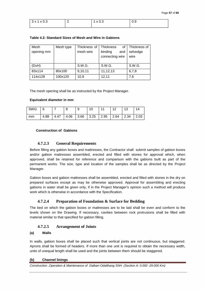
Page 57 of 69
Construction ,Operation & Maintenance of Dalbari-Odalthang SNH (Section A: 0.000 -29.000 Km)
3 x 1 x 0.3 2 1 x 0.3 0.9
Table 4.2: Standard Sizes of Mesh and Wire in Gabions
Mesh
opening mm
Mesh type Thickness of
mesh wire
Thickness of
binding and
connecting wire
Thickness of
selvedge
wire
(DxH) S.W.G. S.W.G. S.W.G.
83x114 80x100 9,10,11 11,12,13 6,7,8
114x128 100x120 10,9 12,11 7,6
The mesh opening shall be as instructed by the Project Manager.
Equivalent diameter in mm
SWG 6 7 8 9 10 11 12 13 14
mm 4.88 4.47 4.06 3.66 3.25 2.95 2.64 2.34 2.03
Construction of Gabions
4.7.2.3 General Requirements
Before filling any gabion boxes and mattresses, the Contractor shall submit samples of gabion boxes
and/or gabion mattresses assembled, erected and filled with stones for approval which, when
approved, shall be retained for reference and comparison with the gabions built as part of the
permanent works. The size, type and location of the samples shall be as directed by the Project
Manager.
Gabion boxes and gabion mattresses shall be assembled, erected and filled with stones in the dry on
prepared surfaces except as may be otherwise approved. Approval for assembling and erecting
gabions in water shall be given only, if in the Project Manager's opinion such a method will produce
work which is otherwise in accordance with the Specification.
4.7.2.4 Preparation of Foundation & Surface for Bedding
The bed on which the gabion boxes or mattresses are to be laid shall be even and conform to the
levels shown on the Drawing. If necessary, cavities between rock protrusions shall be filled with
material similar to that specified for gabion filling.
4.7.2.5 Arrangement of Joints
(a) Walls
In walls, gabion boxes shall be placed such that vertical joints are not continuous, but staggered.
Aprons shall be formed of headers. If more than one unit is required to obtain the necessary width,
units of unequal length shall be used and the joints between them should be staggered.
(b) Channel linings
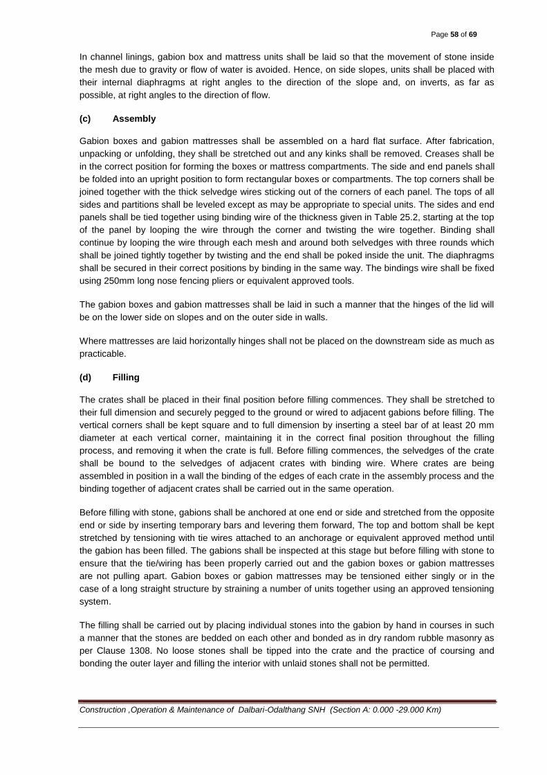
Page 58 of 69
Construction ,Operation & Maintenance of Dalbari-Odalthang SNH (Section A: 0.000 -29.000 Km)
In channel linings, gabion box and mattress units shall be laid so that the movement of stone inside
the mesh due to gravity or flow of water is avoided. Hence, on side slopes, units shall be placed with
their internal diaphragms at right angles to the direction of the slope and, on inverts, as far as
possible, at right angles to the direction of flow.
(c) Assembly
Gabion boxes and gabion mattresses shall be assembled on a hard flat surface. After fabrication,
unpacking or unfolding, they shall be stretched out and any kinks shall be removed. Creases shall be
in the correct position for forming the boxes or mattress compartments. The side and end panels shall
be folded into an upright position to form rectangular boxes or compartments. The top corners shall be
joined together with the thick selvedge wires sticking out of the corners of each panel. The tops of all
sides and partitions shall be leveled except as may be appropriate to special units. The sides and end
panels shall be tied together using binding wire of the thickness given in Table 25.2, starting at the top
of the panel by looping the wire through the corner and twisting the wire together. Binding shall
continue by looping the wire through each mesh and around both selvedges with three rounds which
shall be joined tightly together by twisting and the end shall be poked inside the unit. The diaphragms
shall be secured in their correct positions by binding in the same way. The bindings wire shall be fixed
using 250mm long nose fencing pliers or equivalent approved tools.
The gabion boxes and gabion mattresses shall be laid in such a manner that the hinges of the lid will
be on the lower side on slopes and on the outer side in walls.
Where mattresses are laid horizontally hinges shall not be placed on the downstream side as much as
practicable.
(d) Filling
The crates shall be placed in their final position before filling commences. They shall be stretched to
their full dimension and securely pegged to the ground or wired to adjacent gabions before filling. The
vertical corners shall be kept square and to full dimension by inserting a steel bar of at least 20 mm
diameter at each vertical corner, maintaining it in the correct final position throughout the filling
process, and removing it when the crate is full. Before filling commences, the selvedges of the crate
shall be bound to the selvedges of adjacent crates with binding wire. Where crates are being
assembled in position in a wall the binding of the edges of each crate in the assembly process and the
binding together of adjacent crates shall be carried out in the same operation.
Before filling with stone, gabions shall be anchored at one end or side and stretched from the opposite
end or side by inserting temporary bars and levering them forward, The top and bottom shall be kept
stretched by tensioning with tie wires attached to an anchorage or equivalent approved method until
the gabion has been filled. The gabions shall be inspected at this stage but before filling with stone to
ensure that the tie/wiring has been properly carried out and the gabion boxes or gabion mattresses
are not pulling apart. Gabion boxes or gabion mattresses may be tensioned either singly or in the
case of a long straight structure by straining a number of units together using an approved tensioning
system.
The filling shall be carried out by placing individual stones into the gabion by hand in courses in such
a manner that the stones are bedded on each other and bonded as in dry random rubble masonry as
per Clause 1308. No loose stones shall be tipped into the crate and the practice of coursing and
bonding the outer layer and filling the interior with unlaid stones shall not be permitted.
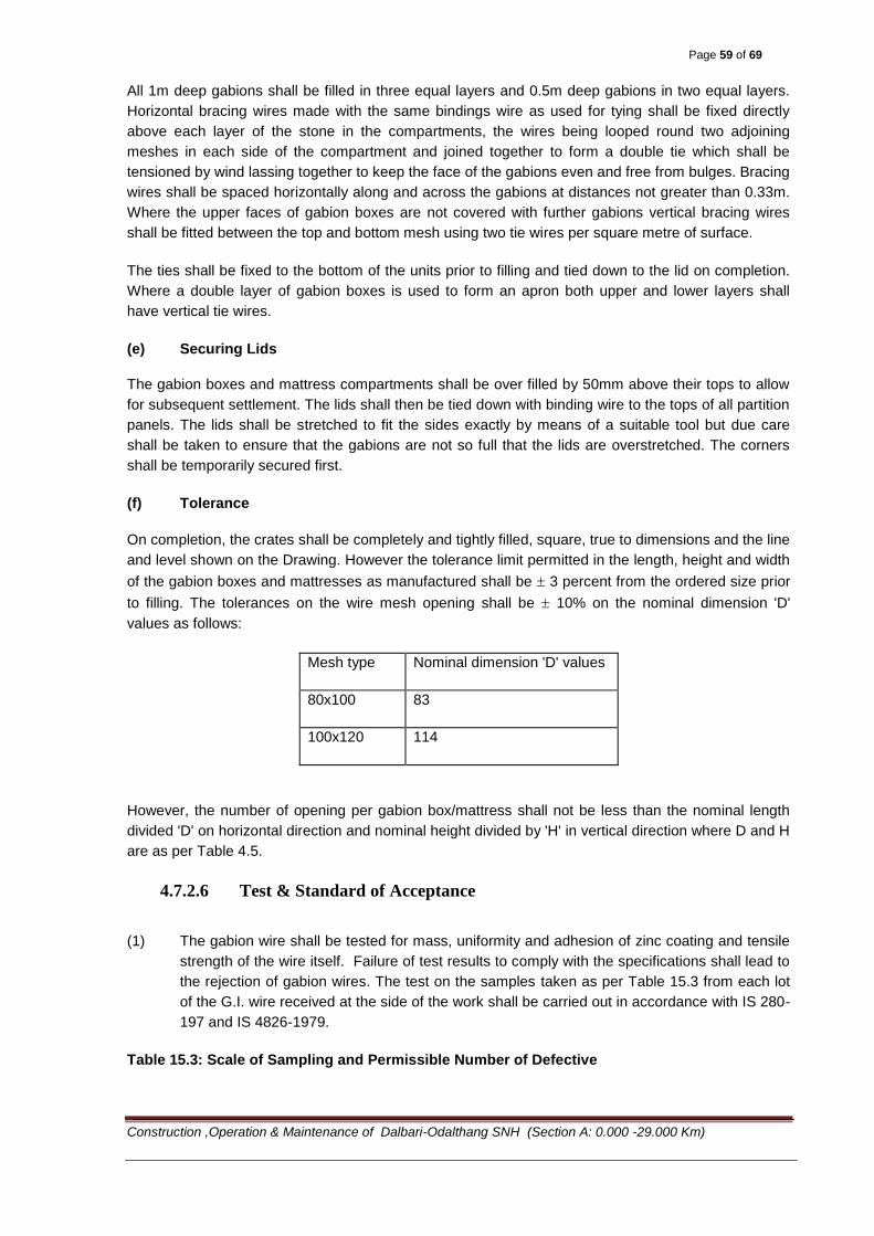
Page 59 of 69
Construction ,Operation & Maintenance of Dalbari-Odalthang SNH (Section A: 0.000 -29.000 Km)
All 1m deep gabions shall be filled in three equal layers and 0.5m deep gabions in two equal layers.
Horizontal bracing wires made with the same bindings wire as used for tying shall be fixed directly
above each layer of the stone in the compartments, the wires being looped round two adjoining
meshes in each side of the compartment and joined together to form a double tie which shall be
tensioned by wind lassing together to keep the face of the gabions even and free from bulges. Bracing
wires shall be spaced horizontally along and across the gabions at distances not greater than 0.33m.
Where the upper faces of gabion boxes are not covered with further gabions vertical bracing wires
shall be fitted between the top and bottom mesh using two tie wires per square metre of surface.
The ties shall be fixed to the bottom of the units prior to filling and tied down to the lid on completion.
Where a double layer of gabion boxes is used to form an apron both upper and lower layers shall
have vertical tie wires.
(e) Securing Lids
The gabion boxes and mattress compartments shall be over filled by 50mm above their tops to allow
for subsequent settlement. The lids shall then be tied down with binding wire to the tops of all partition
panels. The lids shall be stretched to fit the sides exactly by means of a suitable tool but due care
shall be taken to ensure that the gabions are not so full that the lids are overstretched. The corners
shall be temporarily secured first.
(f) Tolerance
On completion, the crates shall be completely and tightly filled, square, true to dimensions and the line
and level shown on the Drawing. However the tolerance limit permitted in the length, height and width
of the gabion boxes and mattresses as manufactured shall be 3 percent from the ordered size prior
to filling. The tolerances on the wire mesh opening shall be 10% on the nominal dimension 'D'
values as follows:
Mesh type Nominal dimension 'D' values
80x100 83
100x120 114
However, the number of opening per gabion box/mattress shall not be less than the nominal length
divided 'D' on horizontal direction and nominal height divided by 'H' in vertical direction where D and H
are as per Table 4.5.
4.7.2.6 Test & Standard of Acceptance
(1) The gabion wire shall be tested for mass, uniformity and adhesion of zinc coating and tensile
strength of the wire itself. Failure of test results to comply with the specifications shall lead to
the rejection of gabion wires. The test on the samples taken as per Table 15.3 from each lot
of the G.I. wire received at the side of the work shall be carried out in accordance with IS 280-
197 and IS 4826-1979.
Table 15.3: Scale of Sampling and Permissible Number of Defective

Page 60 of 69
Construction ,Operation & Maintenance of Dalbari-Odalthang SNH (Section A: 0.000 -29.000 Km)
No. of coils in a lot No. of coils randomly
selected for sampling*
Permissible No. of
defective coil
Up to 25 2 0
26-50 3 0
51-150 5 0
151-300 8 1
300 and above 13 1
* One sample per coil shall be tested in all respect.
(2) The stones shall be tested for water absorption. At least 3 set of tests shall be made for every
source of material. The test results shall meet the specified criteria.
4.8 Measurement and Payment
Measurement shall be in cubic meters of gabion crates filled with stones and complete in place and
quantity shall be calculated from the dimension of the gabions indicated in the Drawing or ordered by
the Project Manager.
Payment shall be made as per respective contract unit rate which shall be the full and the final
compensation to the Contractor as per Clause 115 to complete the work in accordance with these
Specifications.
4.9 Elastomeric Bridge Bearings
4.9.1 Scope
The purpose of bridge bearing is to spread the load over a pre-determined area of beam above and of
the pier and abutment below, while permitting an adequate amount of elastic and temperature
movements. The degree of sophistication needed in a bearing will depend on the load to be carried
and the number of movements (e.g. translations and rotations) to be allowed for; also for the lateral
forces to be resisted in a direction at right angles to the primary movements.
Design life of bearing is not generally as long as the bridge. Provision must be made for their
replacement as well as their regular inspection. This requires that the bridge can be jacked up and
that bearings can be removed without too much difficulty.
4.9.2 Steel reinforced Elastomeric Bearings
An elastomeric bridge bearing is a device constructed partially or wholly from elastomer. The purpose
of this is to transmit loads and accommodate movements between a bridge superstructure and its
supporting structure. Steel-reinforced elastomeric bearing shall consist of alternate layer of steel
reinforcement and elastomer bonded together. In addition to any internal reinforcement, bearings may
have external steel load plated bonded to either or both the upper or lower elastomer layers.
Bearings should be furnished with dimensions, material properties, elastomer grade and type of
laminates required by the drawings.
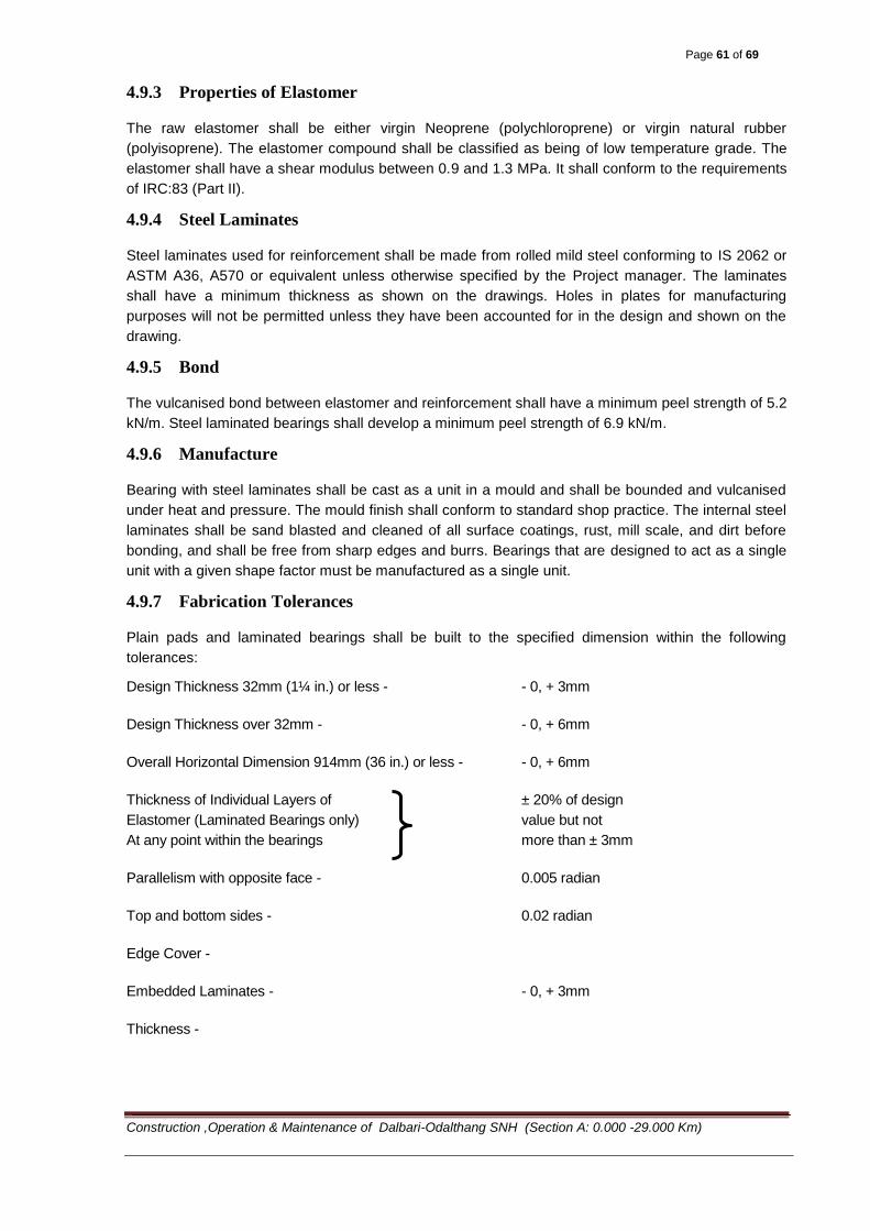
Page 61 of 69
Construction ,Operation & Maintenance of Dalbari-Odalthang SNH (Section A: 0.000 -29.000 Km)
4.9.3 Properties of Elastomer
The raw elastomer shall be either virgin Neoprene (polychloroprene) or virgin natural rubber
(polyisoprene). The elastomer compound shall be classified as being of low temperature grade. The
elastomer shall have a shear modulus between 0.9 and 1.3 MPa. It shall conform to the requirements
of IRC:83 (Part II).
4.9.4 Steel Laminates
Steel laminates used for reinforcement shall be made from rolled mild steel conforming to IS 2062 or
ASTM A36, A570 or equivalent unless otherwise specified by the Project manager. The laminates
shall have a minimum thickness as shown on the drawings. Holes in plates for manufacturing
purposes will not be permitted unless they have been accounted for in the design and shown on the
drawing.
4.9.5 Bond
The vulcanised bond between elastomer and reinforcement shall have a minimum peel strength of 5.2
kN/m. Steel laminated bearings shall develop a minimum peel strength of 6.9 kN/m.
4.9.6 Manufacture
Bearing with steel laminates shall be cast as a unit in a mould and shall be bounded and vulcanised
under heat and pressure. The mould finish shall conform to standard shop practice. The internal steel
laminates shall be sand blasted and cleaned of all surface coatings, rust, mill scale, and dirt before
bonding, and shall be free from sharp edges and burrs. Bearings that are designed to act as a single
unit with a given shape factor must be manufactured as a single unit.
4.9.7 Fabrication Tolerances
Plain pads and laminated bearings shall be built to the specified dimension within the following
tolerances:
Design Thickness 32mm (1¼ in.) or less - - 0, + 3mm
Design Thickness over 32mm - - 0, + 6mm
Overall Horizontal Dimension 914mm (36 in.) or less - - 0, + 6mm
Thickness of Individual Layers of ± 20% of design
Elastomer (Laminated Bearings only) value but not
At any point within the bearings more than ± 3mm
Parallelism with opposite face - 0.005 radian
Top and bottom sides - 0.02 radian
Edge Cover -
Embedded Laminates - - 0, + 3mm
Thickness -
Page 62 of 69
Construction ,Operation & Maintenance of Dalbari-Odalthang SNH (Section A: 0.000 -29.000 Km)
Top and bottom cover Layer - - 0, the smaller of + 1.5mm and + 20% of
the nominal cover layer
thickness.
4.9.8 Marking and Certifying
The manufacturer shall certify that each bearing satisfies the requirements of the drawings and these
specifications, and shall supply a certified copy of material test results. Each reinforced bearing shall
be marked with indelible ink or flexible paint the bearing identification number, elastomer type and
grade number. The marking shall be on the face that is visible after erection of the bridge.
4.9.9 Testing
i) General
Materials for elastomeric bearings and the finished bearings themselves shall be subjected to the
tests described in the drawings.
ii) Ambient Temperature Tests on the Elastomer
The elastomer used shall at least satisfy the limits prescribed in the AASHTO for durometer hardness,
tensile strength, ultimate elongation, heat resistance, compression set, and ozone resistance. The
bond to the reinforcement, if any, shall also satisfy the requirement of Article 4.9.5 above. The shear
modulus of the material shall be tested at 23°c (73°F) using the apparatus and procedure described in
Annexure A of ASTM D4014. It shall be either equal to or greater than the value shown on the
drawing.
iii) Visual Inspection of the Finished Bearing
Every finished bearing shall be inspected for compliance with dimensional tolerances and for overall
quality of manufacture. In steel reinforced bearings, the edges of the steel shall be protected
everywhere from corrosion.
iv) Short Duration Compression Tests on Bearings
The bearing shall be loaded in compression to 1.5 times the maximum design load. The load shall be
held constant for 5 minutes, removed, and re-applied for another 5 minutes. The bearing shall be
examined visually while under the second loading. If the bulging pattern suggests laminate parallelism
or a layer thickness that is outside the specified tolerances, or poor laminate bond the bearing shall be
rejected. If there are three or more separate surface cracks that are greater than 0.2mm (0.08 in.)
wide and 0.2mm (0.08 in.) deep, the bearing shall be rejected.
v) Long-Duration Compression Tests on Bearings
The bearing shall be loaded in compression to 1.5 times its maximum design load for a minimum
period of 15 hours. If, during the test, the load falls below 1.3 times the maximum design load, the test
duration shall be increased by the period of time for which the load is below this limit. The bearing
shall be examined visually at the end of the test while it is still under load. If the bulging pattern
suggests laminate parallelism or a layer thickness that is outside the specified tolerances or poor
laminate bond the bearing shall be rejected. If there are three or more separate surface cracks that
are greater than 0.2mm (0.08 in.) wide and 0.2mm (0.08 in.) deep, the bearing shall be rejected.
vi) Shear Modulus Tests on Material from Bearings
Page 63 of 69
Construction ,Operation & Maintenance of Dalbari-Odalthang SNH (Section A: 0.000 -29.000 Km)
The shear modulus of the material in the finished bearing shall be evaluated by testing a specimen cut
from it using the procedure given in annex A of ASTM D4014. If the test is conducted on finished
bearings, the material shear modulus shall be computed from the measured shear stiffness of the
bearing, taking due account of the influence on shear stiffness of bearing geometry and compressive
load.
4.9.10 Installation
Bearings shall be placed on surfaces that are plane to within 1.5mm (1/16 in.) and horizontal to within
0.01 radian. Any lack of parallelism between the top of the bearing and the underside of the girder that
exceeds 0.01 radian shall be corrected by grouting or as otherwise directed by the Project manager.
In order to function correctly the elastomeric bearings must be placed with particular care.
As a general rule, the bearings must be placed on a perfectly plane and horizontal surface. A 30 to 40
mm high mortar pad or for larger height the RC pad is cast onto the base concrete, which must be
previously carefully roughened. The dimensions of the pad must be by 30 to 50 mm larger than those
of the bearing.
When minimum loads are small, it is recommended to glue the bearing to the support with an epoxy
resin.
The bottom face of the pre-cast unit, in contact with the bearing, must be perfectly plane and
horizontal.
For cast-in-situ structures, the bearing is placed on the support and the structure cast on the bearing.
The shuttering surrounding the bearing must be removable at the time of stripping the forms and at
the same time it must be strong enough to resist the weight of concrete. If the base shuttering fails,
the bearing will be partially embedded in the concrete and the distortions hindered. Future lifting of the
structure may become more difficult.
4.10 Measurement and Payment
Elastomeric bearing is measured by the total number of complete bearing installed at the specified
bridge location.
Elastomeric bearing measured in accordance with Section 4.10 shall be paid for at the Contract unit
prices for providing bearings in the locations indicated on the Drawings and described in the Bill of
Quantities. Payment shall be full compensation for furnishing and installing all materials, including all
labor, tools, equipment and incidentals necessary to complete the work.
4.11 Movement or Expansion Joints
4.11.1 Scope of Work
The scope of work will include:
i) Preparation of detailed engineering and installation drawings, supply and supervision during fixing of
strip seal/compression seal expansion joints conforming to specifications. The expected
expansion/contraction of the superstructure at the location of expansion joints are shown in relevant
approved drawings.
ii) Design manufacture, providing and seating of expansion joints by the specialized agency and
approved by the Project manager.
Page 64 of 69
Construction ,Operation & Maintenance of Dalbari-Odalthang SNH (Section A: 0.000 -29.000 Km)
iii) Necessary technical supervision for installation of each and every expansion joint during different
stages of installation including rectification of any deficiency or defect attributable to fixing and
installation will be provided by the manufacturer/supplier. The expansion joint shall be provided for the
full width of bridge including the railing. Leak tightness of all joints shall be ensured.
4.11.2 Specification for Strip Seal Expansion Joint
Expansion joint type described here–after is the “strip seal type”, but alternate designs can be
proposed for the Project manager’s approval.
4.11.2.1 Components:
Strip seal expansion joint shall comprise the following items:
a) Edge beam:
This shall be either extruded or hot rolled steel section or cold rolled cellular steel section with suitable
profile to mechanically lock the swelling element in place throughout the normal movement cycle.
Further the configuration shall be such that the section has a minimum thickness of 10 mm all along
its cross section (flanges and web) the minimum height of the edge beam section shall be 50 mm and
the minimum cross sectional area of the edge beam shall be 1500 sq.mm.
b) Anchorage:
Edge beams shall be anchored to the deck/dirt wall/approach slab by reinforcing bars or bolts or
anchor plates cast in concrete or a combination of anchor plate and reinforcing bars. Anchor bars
studs or bolts shall engage the main structural reinforcement of the deck and in case of anchor plates
or loops, this shall be achieved by passing transverse bars through the loops or plates.
The minimum thickness of anchor plate shall be 12 mm. Total cross sectional area of bar on each
side of the joint shall not be less than 1600 sq.mm per meter length of the joint and the center to
center spacing shall not exceed 250 mm. The ultimate resistance of anchors shall not be less than
600 kN/m in any direction.
4.11.2.2 Material
a. The steel for edge beams shall conform to any of the steel grade corresponding to RST 37-2 or 37-3 (DIN), ASTM A 36 or A 588, CAN/CSA standard G40.21 Grade 300W or equivalent. b. Anchorage steel shall conform to IS: 2062 or equivalent.
c. All steel sections shall be protected against corrosion by hot dip galvanizing or any other approved
anticorrosive coating with a minimum thickness of 100 micron.
d. Chloroprene of strip seal element shall conform to clause 9151.1 of IRC:83 (Part-ll) The properties
of chloroprene shall be as specified in Table 4.11-1
4.11.2.3 Fabrication (Pre-installation)
a. The strip seal joint system and all its component parts including anchorages shall be supplied by
the manufacturer/ system supplier.
b. The width of the gap to cater for movement due to thermal effect, pre stress, shrinkage and creep,
superstructure deformations (if any) and sub-structure deformations (if any) shall be determined and

Page 65 of 69
Construction ,Operation & Maintenance of Dalbari-Odalthang SNH (Section A: 0.000 -29.000 Km)
intimated to the manufacturer depending upon the temperature at which the joint is to be installed, the
gap dimension shall be preset.
Table 4.11-1 Strip Seal Element Specifications
Sl. No Property Specified Value
1 Hardness 63+/- shore A
2 DIN 53505 55+/- Shore A
3 ASTM D (Modified)
4 Tensile strength Min. 11 MPa
5 DIN 53504 Min. 13.8 MPa
6 ASTM D412
7 Elongation at fracture Min. 350 per cent
8 DIN 53504 Min. 250 per cent
9 ASTM D412
10 Tear Propagation strength Min. 10 N/mm
11 Longitudinal Min. 10N/mm
12 Transverse Min. 25 per cent
13 Shock elasticity Min 220 Cu. mm
14 Abrasion
15 Residual compressive strain (22/70 deg C/30 per cent)
Aging in hot air (14 days/70 degC)
Max. 28 per cent
16 Change in hardness Max. +7 Shore A
17 Change in tensile strength Max. -20 per cent
18 Change in elongation at fracture -20 per cent
19 Aging in ozone (24h/50pphm/25 deg per cent
elongation)
No cracks
20 Swelling behaviour in oil (168h/28 deg/C)
21 ASTM Oil No. 1 Max. +5 per cent
22 Volume Change Max. -20 Shore A
23 Change in hardness Max. -35 deg C
24 ASTM Oil No. 3 Max. +25 per cent
25 Volume change Max. -25 Shore A
26 Change in hardness Max. -35 deg C
27 Cold Hardening Point
c. Each strip seal expansion joint system shall be fabricated as a single entity unless stage
construction or excessive length prohibits monolithic fabrication. It shall fit the full width of the
structure as indicated on the approved drawing. The system shall be pre-set by the manufacturer prior
to transportation. Presetting shall be done in accordance with the joint opening indicated on the
drawing.
d. The finally assembled joint shall them be clamped and transported to the work site.
4.11.2.4 Handling and Storage
a. For transportation and storage, auxiliary brackets shall be provided to hold the joint assembly
together.
Page 66 of 69
Construction ,Operation & Maintenance of Dalbari-Odalthang SNH (Section A: 0.000 -29.000 Km)
b. The manufacture/ supplier shall supply either directly to the Project manager or to the Bridge
Contractor all the materials of strip seal joints including sealants and all other accessories for the
effective installation of the jointing.
c. Expansion joint material shall be handled with care. It shall be stored under cover on suitable
lumber padding.
4.11.2.5 Supply/ Installation
Components of expansion joint such as edge beam and strip seal shall be arranged by the contractor
by procuring the same from reputed approved manufacturer to ensure quality and performance.
Contractor shall furnish a warranty of trouble free performance for at least ten years and free
rectification of defects / replacement, if any, during this period.
The joints shall be installed in compliance to the manufacturer’s instructions for installation.
Taking the width of gap for movement of the joint into account the dimensions of the recess in the
decking shall be established in accordance with the drawings or design data of the manufacturer. The
surfaces of the recess shall be thoroughly cleaned and all dirt and debris removed. The exposed
reinforcement shall be suitably adjusted to permit unobstructed lowering of the joint into the recess.
The recess shall be shuttered in such a way that dimensions in the joint drawing are maintained. The
formwork shall be rigid and firm.
Immediately prior to placing the joint, the presetting shall be inspected. Should the actual temperature
of the structure be different from the temperature provided for presetting, correction of the presetting
shall be done. After adjustment the brackets shall be tightened again.
The joint shall be lowered in a pre-determined position. Following placement of the joint in the
prepared recess, the joint shall be leveled and finally aligned and the anchorage steel on one side of
the joint welded to the exposed reinforcement bars of the structure. Upon completion, the same
procedure shall be followed for the other side of the joint. With the expansion joint finally held at both
sides, the auxiliary brackets shall be released allowing the joint to take up the movement of the
structure.
High quality concrete shall then be filled into the recess. The packing concrete must feature low
shrinkage and have the same strength as that of the superstructure but in any case not less than M30
grade good compaction and careful curing of concrete is particularly important.
After the concrete has cured, the movable installation brackets and shuttering still in place shall be
removed.
The neoprene seal shall be field installed in continuous length spanning the entire roadway width. To
ensure proper fit of seal and enhance the ease of installation dirt, spatter or standing water shall be
removed from the steel cavity using a brush, scrapper or compressed air. The seal shall be installed
without any damage to the seal by suitable hand method or machine tools.
The deck surfacing shall be finished flush with the top of the steel sections, the horizontal leg of the
edge beam shall be cleaned beforehand. It is particularly important to ensure thorough and careful
compaction of the surfacing in order to prevent any premature depression forming in it.
Page 67 of 69
Construction ,Operation & Maintenance of Dalbari-Odalthang SNH (Section A: 0.000 -29.000 Km)
4.11.2.6 Acceptance criteria
a. All steel elements shall be finished with corrosion protection system
b. For neoprene seal, the acceptance test shall conform to the requirements stipulated in Table
4.11-1. The manufacturer/ supplier shall produce a test certificate accordingly, conducted in a
recognized laboratory, in India or abroad.
c. The manufacturer shall produce test certificates indicating that anchorage system had been tested
in recognized laboratory to determine optimum configuration of anchorage assembly under dynamic
loading.
d. Prior to acceptance 25 percent of the completed and installed joints, subject to a minimum of one
joint, shall be subjected to water tightness test. Water shall be continuously pounded along the entire
length for a minimum period of 4 hours for a depth of 25mm above the highest point of deck. The
width of ponding shall be at least 50mm beyond the anchorage block of the joint on either side. The
depth of water shall not fall below 25mm anytime during the test. A close inspection of the underside
of the joint shall not reveal any leakage.
e. As strip seal type of joint is specialized in nature, generally of the proprietary type, the manufacturer
shall be required to produce evidence of satisfactory performance of this type of joint.
4.11.2.7 Test and standards or acceptance:
The materials shall be tested in accordance with these specifications and shall meet the prescribed
criteria. The manufacturer/supplier shall furnish the requisite certificates from the recognized
laboratory in India or abroad.
4.12 Measurement and Payment
Expansion joints shall be measured by the linear Meter of complete joint installed, measurement
being along a straight line from base to top of a wall or one side of a slab to the other, etc. The
measured length may therefore include a sealant length of over twice this value if several faces of the
concrete are sealed.
Expansion joints measured in accordance with Section 4.12 shall be paid for at the Contract unit
prices for providing joints in the locations indicated on the Drawings and described in the Bill of
Quantities. Payment shall be full compensation for furnishing and installing all materials, including all
labor, tools, equipment and incidentals necessary to complete the work.
5.0 SECTION 5: DAY WORKS
5.1 General
Work shall not be executed on a Daywork basis except by written order of the Project Manager. Bidders shall enter basic rates for Daywork items in the Schedules, which rates shall apply to any quantity of Daywork ordered by the Project Manager. Nominal quantities have been indicated against each item of Daywork, and the bidders must provide competitive rates for each item.
5.2 Dayworks Labour
In calculating payments due to the Contractor for the execution of Daywork, the hours for labour will be reckoned from the time of arrival of the labour at the job site to execute the particular item of Daywork to the time of return to the original place of departure, but excluding meal breaks and rest
Page 68 of 69
Construction ,Operation & Maintenance of Dalbari-Odalthang SNH (Section A: 0.000 -29.000 Km)
periods. Only the time of classes of labour directly doing work ordered by the Project Manager and for which they are competent to perform will be measured. The time of gangers (charge hands) actually doing work with the gangs will also be measured but not the time of foremen or other supervisory personnel.
The Contractor shall be entitled to payment in respect of the total time that labor is employed on Daywork, calculated at the rates quoted in the Daywork of BOQ. The rates for labor shall be deemed to cover all costs to the Contractor including (but not limited to) the amount of wages paid to such labor, transportation time, overtime, subsistence allowances, and any sums paid to or on behalf of such labor for social benefits in accordance with law of Kingdom of Bhutan, as well as Contractor's profit, overheads, superintendence, liabilities and insurance and allowance to labor, timekeeping and clerical and office work, the use of consumable stores, water, lighting and power; the use and repair of staging, scaffoldings, workshops and stores, portable power tools; supervision by the Contractor's staff, foremen and other supervisory personnel; and charges incidental to the foregoing. The rates shall be stated in the local currency.
5.3 Dayworks Materials
The Contractor shall be entitled to payment in respect of materials used for Daywork (except for materials for which the cost is included in the percentage addition to labour costs as detailed heretofore), at the rates entered by him in the Materials section of Daywork, and shall be deemed to include overhead charges and profit as follows;
(a) the rates for materials shall be calculated on the basis of the invoiced price, freight,
insurance, handling expenses, damage, losses, etc., and shall provide for delivery to store for stockpiling at the Site. The rates shall be stated in local currency.
(b) the cost of hauling materials for use on work ordered to be carried out as Daywork from the
store or stockpile on the Site to the place where it is to be used will be paid in accordance with the terms for labor and Constructional Plant in this Schedule.
5.4 Dayworks Plant
The Contractor shall be entitled to payments in respect of Construction Equipment already on Site and employed on Dayworks at the rental rates entered by him in the Construction Plant section of Dayworks. The said rates shall be deemed to include due and complete allowance for depreciation, interest, indemnity, and insurance, repairs, maintenance, supplies, fuel, lubricants, and other consumables, cost of drivers, operation and assistants and all overhead, profit, and administrative costs related to the use of such equipment.
In calculating the payment due to the Contractor for Construction Plants employed on Dayworks, only the actual number of working hours will be eligible for payment.
The rental rates for Constructional Plant employed on Dayworks shall be stated in local currency.