Embed Size (px)
Citation preview

1
• A. J. Clark School of Engineering •Department of Civil and Environmental Engineering
Sixth EditionCHAPTER
12b
Construction Planning, Equipment, and Methods
DRILLING ROCK AND EARTH DRILLING ROCK AND EARTH
ByByDr. Ibrahim AssakkafDr. Ibrahim Assakkaf
ENCEENCE 420 420 –– Construction Equipment and MethodsConstruction Equipment and MethodsSpring 2003 Spring 2003
Department of Civil and Environmental EngineeringDepartment of Civil and Environmental EngineeringUniversity of Maryland, College ParkUniversity of Maryland, College Park
CHAPTER 12b. DRILLING ROCK AND EARTHENCE 420 ©Assakkaf
Slide No. 73
SELECTING THE DRILLING SELECTING THE DRILLING METHOD AND EQUIPMENTMETHOD AND EQUIPMENT
The drilling pattern should be The drilling pattern should be planned to produce rock sizes that planned to produce rock sizes that are small enough to permit most of are small enough to permit most of them to be handled by the them to be handled by the excavator, such as a loader or excavator, such as a loader or shovel, or to pass into the crusher shovel, or to pass into the crusher opening without secondary opening without secondary blasting.blasting.

2
CHAPTER 12b. DRILLING ROCK AND EARTHENCE 420 ©Assakkaf
Slide No. 74
DRILLING JOB ANALYSISDRILLING JOB ANALYSIS
In analyzing a job for drilling and In analyzing a job for drilling and blasting operations, there are four blasting operations, there are four factorsfactors to be considered:to be considered:1.The cubic yards of rock per linear foot of hole.2.The number of pounds of explosive per cubic
yard of rock.3.The number of pounds of explosive per linear
foot of hole.4.Will the resulting breakage meet the job
requirements?
CHAPTER 12b. DRILLING ROCK AND EARTHENCE 420 ©Assakkaf
Slide No. 75
DRILLING JOB ANALYSISDRILLING JOB ANALYSIS
NoteNote:The value of each of the :The value of each of the first three factors first three factors may be estimated in advance of drilling may be estimated in advance of drilling and blasting operationsand blasting operations, but after , but after experimental drilling operations are experimental drilling operations are conducted, it probably will be desirable to conducted, it probably will be desirable to modify the values to give better results. modify the values to give better results.
The The fourth factor is more subjective, but the fourth factor is more subjective, but the relationship between hole size and spacingrelationship between hole size and spacinggives some indication of expected results.gives some indication of expected results.

3
CHAPTER 12b. DRILLING ROCK AND EARTHENCE 420 ©Assakkaf
Slide No. 76
The relationships between the first The relationships between the first three factors are illustrated in Table 1.three factors are illustrated in Table 1.The volumes of rock per linear foot of The volumes of rock per linear foot of hole are based on the net depth of hole are based on the net depth of holes and do not include subholes and do not include sub--drilling, drilling, which usually will be necessary. which usually will be necessary. The pounds of explosive per linear foot The pounds of explosive per linear foot of hole are based on filling the holes of hole are based on filling the holes completely with 60% dynamite. completely with 60% dynamite.
DRILLING JOB ANALYSISDRILLING JOB ANALYSIS
CHAPTER 12b. DRILLING ROCK AND EARTHENCE 420 ©Assakkaf
Slide No. 77
Table 1 (Table 12-4, Text)Drilling and Blasting Data

4
CHAPTER 12b. DRILLING ROCK AND EARTHENCE 420 ©Assakkaf
Slide No. 78
The pounds of explosive per cubic The pounds of explosive per cubic yard of rock are based on filling yard of rock are based on filling each hole to 100, 75, and 50% of each hole to 100, 75, and 50% of its total capacity with dynamite. its total capacity with dynamite. When a hole is not filled When a hole is not filled completely with dynamite, the completely with dynamite, the surplus volume is filled with surplus volume is filled with stemming. stemming.
DRILLING JOB ANALYSISDRILLING JOB ANALYSIS
CHAPTER 12b. DRILLING ROCK AND EARTHENCE 420 ©Assakkaf
Slide No. 79
RATES OF DRILLING ROCKRATES OF DRILLING ROCK
The rates of drilling rock will vary with The rates of drilling rock will vary with a number of a number of factorsfactors such as:such as:
The type of drill and bit size, Hardness of the rock, Depth of holes, Drilling pattern, Terrain, andTime lost waiting for other operations.

5
CHAPTER 12b. DRILLING ROCK AND EARTHENCE 420 ©Assakkaf
Slide No. 80
RATES OF DRILLING ROCKRATES OF DRILLING ROCK
If pneumatic drills are used, the If pneumatic drills are used, the rate of rate of drilling will vary with the pressure of drilling will vary with the pressure of the air.the air.The portion of time that a drill is The portion of time that a drill is operative is defined as the operative is defined as the availability availability factorfactor, , which is usually expressed as which is usually expressed as a percent of the total time that the drill a percent of the total time that the drill is expected to be working.is expected to be working.
CHAPTER 12b. DRILLING ROCK AND EARTHENCE 420 ©Assakkaf
Slide No. 81
Historical drill penetration rates based Historical drill penetration rates based on very general rockon very general rock--type type classification is shown in Table 2 classification is shown in Table 2 (Table 12(Table 12--5, Text)5, Text)These rates should be used as a These rates should be used as a guideguideActual project estimates need to be Actual project estimates need to be based on drilling tests of specified based on drilling tests of specified rock which will be encountered.rock which will be encountered.
RATES OF DRILLING ROCKRATES OF DRILLING ROCK

6
CHAPTER 12b. DRILLING ROCK AND EARTHENCE 420 ©Assakkaf
Slide No. 82
Table 2. Drilling Production Rates (Table 12-5, Text)
RATES OF DRILLING ROCKRATES OF DRILLING ROCK
CHAPTER 12b. DRILLING ROCK AND EARTHENCE 420 ©Assakkaf
Slide No. 83
RATES OF DRILLING ROCKRATES OF DRILLING ROCK
Drill bits, rods, and couplings are Drill bits, rods, and couplings are high wear items, and the time high wear items, and the time required to replace or change each required to replace or change each affects the drilling production. affects the drilling production. Table 3 (Table12Table 3 (Table12--6, Text) gives the 6, Text) gives the average life of these high wear items average life of these high wear items based on the drill footage and the based on the drill footage and the type of rock.type of rock.

7
CHAPTER 12b. DRILLING ROCK AND EARTHENCE 420 ©Assakkaf
Slide No. 84
RATES OF DRILLING ROCKRATES OF DRILLING ROCK
Table 3 (Table 12-6b, Text)
CHAPTER 12b. DRILLING ROCK AND EARTHENCE 420 ©Assakkaf
Slide No. 85
OPTIMUM AIR PRESSURE OPTIMUM AIR PRESSURE FOR DRILLINGFOR DRILLING
Figure 1 (Fig 11Figure 1 (Fig 11--15 Text) shows 15 Text) shows the relationship between the the relationship between the average rate of penetration and average rate of penetration and the operating pressure for each the operating pressure for each group of drills. group of drills. Figure 2 (Fig 11Figure 2 (Fig 11--16, Text) is a 16, Text) is a nomogramnomogram based on the based on the information appearing in Fig. 13information appearing in Fig. 13--15 which indicates the percent 15 which indicates the percent increase in penetration resulting increase in penetration resulting from an increase in air pressure. from an increase in air pressure. Example:Example:If the pressure is increased from If the pressure is increased from 90 to 100 psi, the increase in 90 to 100 psi, the increase in penetration will be 38%.penetration will be 38%.

8
CHAPTER 12b. DRILLING ROCK AND EARTHENCE 420 ©Assakkaf
Slide No. 86
ECONOMY OF INCREASING ECONOMY OF INCREASING AIR PRESSUREAIR PRESSURE
The decision to increase the air pressure at the The decision to increase the air pressure at the drills should not be determined solely on the basis drills should not be determined solely on the basis of the anticipated increase in production and the of the anticipated increase in production and the increase in the cost of compressed air and drilling increase in the cost of compressed air and drilling equipment. equipment. Drilling is only one item in a chain of operations, Drilling is only one item in a chain of operations, which includes drilling, blasting, loading, and which includes drilling, blasting, loading, and hauling. hauling. Figure 3 presents a curve that establishes the Figure 3 presents a curve that establishes the lowest total cost of producing the end product of a lowest total cost of producing the end product of a drilling operation. The curve is plotted to indicate drilling operation. The curve is plotted to indicate this cost for varying air pressures. this cost for varying air pressures.
CHAPTER 12b. DRILLING ROCK AND EARTHENCE 420 ©Assakkaf
Slide No. 87
ECONOMY OF INCREASING ECONOMY OF INCREASING AIR PRESSUREAIR PRESSURE

9
CHAPTER 12b. DRILLING ROCK AND EARTHENCE 420 ©Assakkaf
Slide No. 88
DRILLING PRODUCTION DRILLING PRODUCTION ESTIMATEESTIMATE
To begin a drilling production estimate it is first necessary to make an assumption about the type of equipment that will be used. Tables 12-5 & 12-6 provide information to guide that first decision.
CHAPTER 12b. DRILLING ROCK AND EARTHENCE 420 ©Assakkaf
Slide No. 89
The final equipment decision should only be made after test drilling the formation. Test drilling should help to quantify:
• Penetration rate• Drilling method• Bit size / Bit type
PRODUCTION ESTIMATEPRODUCTION ESTIMATE

10
CHAPTER 12b. DRILLING ROCK AND EARTHENCE 420 ©Assakkaf
Slide No. 90
Penetration Rate is a function of:
• The rock• The drilling method• The size & type of bit
PENETRATION RATEPENETRATION RATE
CHAPTER 12b. DRILLING ROCK AND EARTHENCE 420 ©Assakkaf
Slide No. 91
The rock properties which effect penetration rate are:
• Hardness• Texture• Breaking characteristic• Formation
THE ROCKTHE ROCK
11
CHAPTER 12b. DRILLING ROCK AND EARTHENCE 420 ©Assakkaf
Slide No. 92
HARDNESSHARDNESSHardness is the resistance of a smooth surface toabrasion.It is measured by the MOH scale (Friedrich Mohs).
CHAPTER 12b. DRILLING ROCK AND EARTHENCE 420 ©Assakkaf
Slide No. 93
Hardness is measured by the MOH scale.The scale is from 1 to 10, with
• Diamond rated as 10• Talc rated as 1
HARDNESSHARDNESS

12
CHAPTER 12b. DRILLING ROCK AND EARTHENCE 420 ©Assakkaf
Slide No. 94
HARDNESSHARDNESSScratch Test
Diamond 10.0Schist 5.0 KnifeGranite 4.0 KnifeLimestone 3.0 Copper coinPotash 2.0 FingernailGypsum 1.5 Fingernail
CHAPTER 12b. DRILLING ROCK AND EARTHENCE 420 ©Assakkaf
Slide No. 95
HARDNESSHARDNESSHardness affects drilling speed.
HARDNESS DRILLING SPEED
1-2 FAST
3-4 FAST - MEDIUM
5 MEDIUM
6-7 SLOW - MEDIUM
8-9 SLOW

13
CHAPTER 12b. DRILLING ROCK AND EARTHENCE 420 ©Assakkaf
Slide No. 96
TEXTURETEXTURETexture is the grain structure of the rock.• A loose grained structure
(porous, cavities) drills fast.• Grains large enough to be seen
individually (granite) will drillmedium.
• Fine-grained rocks drill slow.
CHAPTER 12b. DRILLING ROCK AND EARTHENCE 420 ©Assakkaf
Slide No. 97
BREAKING BREAKING CHARACTERISTICCHARACTERISTIC
Describes how the rockbreaks when struck.

14
CHAPTER 12b. DRILLING ROCK AND EARTHENCE 420 ©Assakkaf
Slide No. 98
•• Shatters - into small pieces from a lightblow
• Brittle - breaks easily with a light blow• Shaving - when shaved off in pieces
they break easily• Strong - resists breaking when hit hard• Malleable - flattens instead of breaking
BREAKING BREAKING CHARACTERISTICCHARACTERISTIC
CHAPTER 12b. DRILLING ROCK AND EARTHENCE 420 ©Assakkaf
Slide No. 99
BREAKING BREAKING CHARACTERISTICCHARACTERISTIC• Shatters - drills fast• Brittle - drills fast to medium• Shaving - drills medium• Strong - drills slow to medium• Malleable - drills slow

15
CHAPTER 12b. DRILLING ROCK AND EARTHENCE 420 ©Assakkaf
Slide No. 100
DRILLING METHODDRILLING METHODROTARY-PERCUSSIONThe piston provides striking energy to the rock through
the drill steel. There is rotation so the bit strikes fresh rock with each blow.
CHAPTER 12b. DRILLING ROCK AND EARTHENCE 420 ©Assakkaf
Slide No. 101
Text, FIG. 12-10, 11 & 12
Drill steel
ROTARYROTARYPERCUSSIONPERCUSSION
16
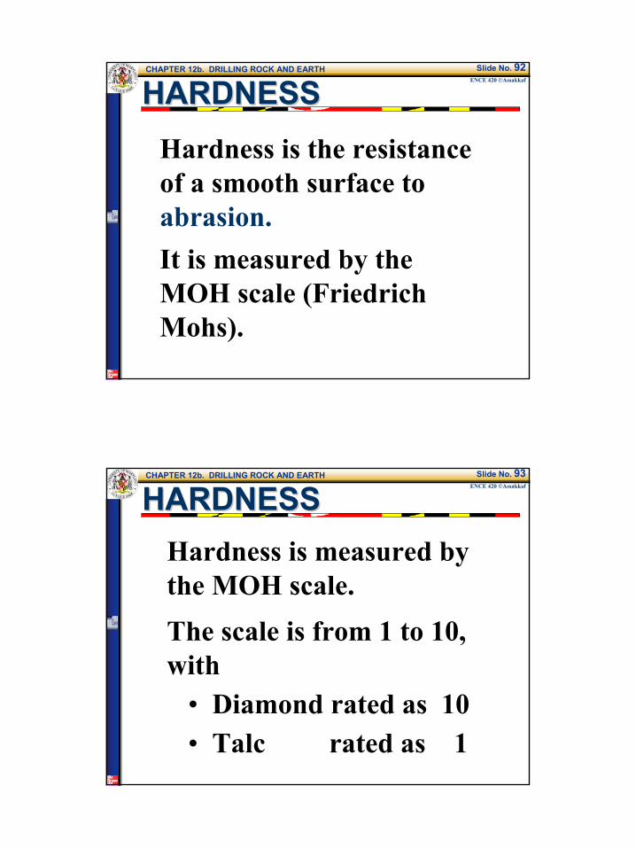
CHAPTER 12b. DRILLING ROCK AND EARTHENCE 420 ©Assakkaf
Slide No. 102
PERCUSSION DRILLINGPERCUSSION DRILLINGHardness
Quartzite 7.0Trap Rock 6.0Schist 5.0Granite 4.0Dolomite 3.5Limestone 3.0Galena 2.5
CHAPTER 12b. DRILLING ROCK AND EARTHENCE 420 ©Assakkaf
Slide No. 103
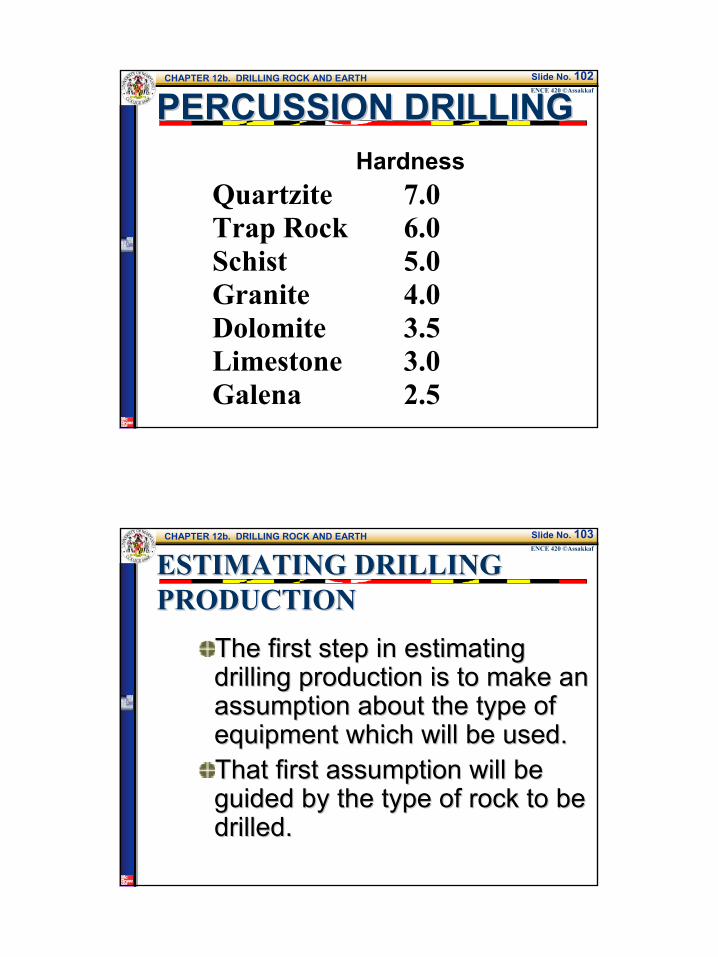
ESTIMATING DRILLING ESTIMATING DRILLING PRODUCTIONPRODUCTION
The first step in estimating The first step in estimating drilling production is to make an drilling production is to make an assumption about the type of assumption about the type of equipment which will be used.equipment which will be used.That first assumption will be That first assumption will be guided by the type of rock to be guided by the type of rock to be drilled.drilled.
17
CHAPTER 12b. DRILLING ROCK AND EARTHENCE 420 ©Assakkaf
Slide No. 104
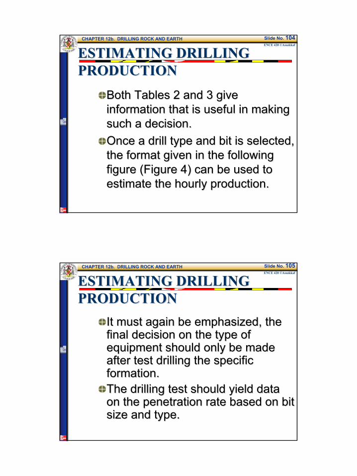
ESTIMATING DRILLING ESTIMATING DRILLING PRODUCTIONPRODUCTION
Both Tables 2 and 3 give Both Tables 2 and 3 give information that is useful in making information that is useful in making such a decision.such a decision.Once a drill type and bit is selected, Once a drill type and bit is selected, the format given in the following the format given in the following figure (Figure 4) can be used to figure (Figure 4) can be used to estimate the hourly production.estimate the hourly production.
CHAPTER 12b. DRILLING ROCK AND EARTHENCE 420 ©Assakkaf
Slide No. 105
ESTIMATING DRILLING ESTIMATING DRILLING PRODUCTIONPRODUCTION
It must again be emphasized, the It must again be emphasized, the final decision on the type of final decision on the type of equipment should only be made equipment should only be made after test drilling the specific after test drilling the specific formation.formation.The drilling test should yield data The drilling test should yield data on the penetration rate based on bit on the penetration rate based on bit size and type. size and type.

18
CHAPTER 12b. DRILLING ROCK AND EARTHENCE 420 ©Assakkaf
Slide No. 106
ESTIMATING DRILLING ESTIMATING DRILLING PRODUCTIONPRODUCTION
Figure 4. Format for Estimating Drilling Production
CHAPTER 12b. DRILLING ROCK AND EARTHENCE 420 ©Assakkaf
Slide No. 107
GUIDELINES FOR ESTIMATING GUIDELINES FOR ESTIMATING DRILLING PRODUCTIONDRILLING PRODUCTION
(1) Depth of Hole:(1) Depth of Hole:Usually, when drilling for loading explosives and blasting, it is necessary to subdrill below the desired final bottom or floor elevation. This extra depth is dependent on the blasting design. Normally, 2 or 3 ft of extra depth is required. Therefore, if the depth to the finish grade is 25 ft (pull depth), it may be necessary to actually drill 28 ft
ft 3or 2 Pull (ft) Drill +=
19
CHAPTER 12b. DRILLING ROCK AND EARTHENCE 420 ©Assakkaf
Slide No. 108
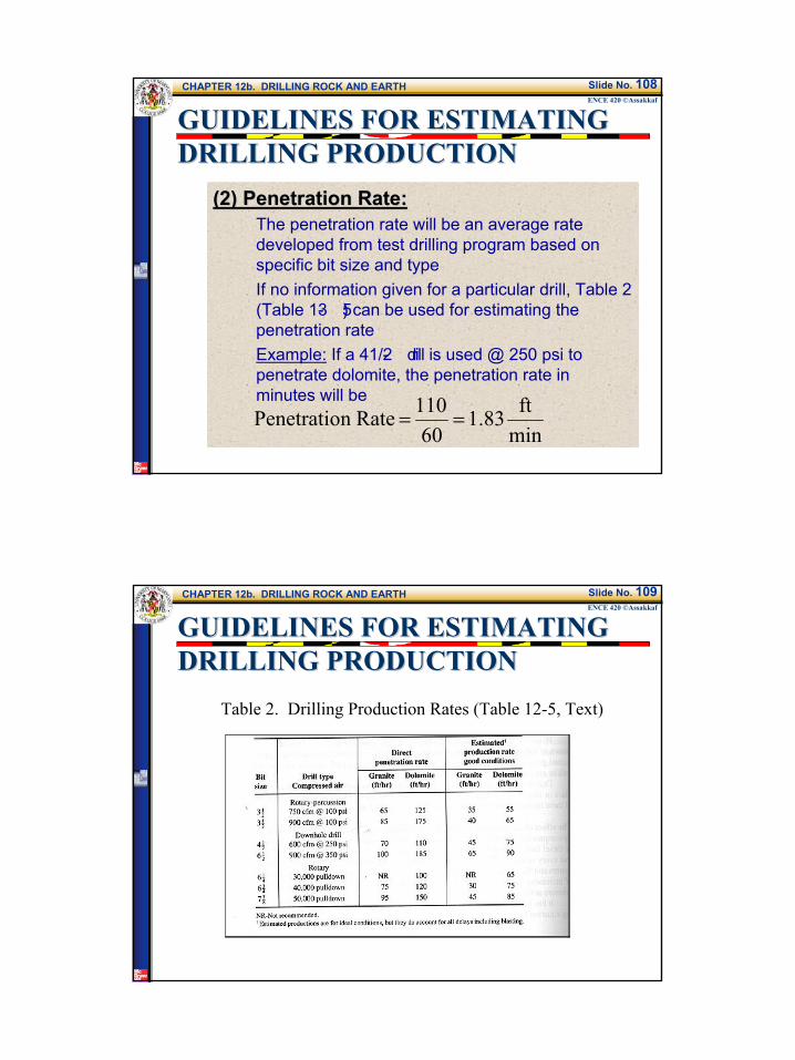
GUIDELINES FOR ESTIMATING GUIDELINES FOR ESTIMATING DRILLING PRODUCTIONDRILLING PRODUCTION
(2) Penetration Rate:(2) Penetration Rate:The penetration rate will be an average rate developed from test drilling program based on specific bit size and typeIf no information given for a particular drill, Table 2 (Table 13- 5) can be used for estimating the penetration rateExample: If a 41/2- drill is used @ 250 psi to penetrate dolomite, the penetration rate in minutes will be
minft83.1
60110 Raten Penetratio ==
CHAPTER 12b. DRILLING ROCK AND EARTHENCE 420 ©Assakkaf
Slide No. 109
GUIDELINES FOR ESTIMATING GUIDELINES FOR ESTIMATING DRILLING PRODUCTIONDRILLING PRODUCTION
Table 2. Drilling Production Rates (Table 12-5, Text)

20
CHAPTER 12b. DRILLING ROCK AND EARTHENCE 420 ©Assakkaf
Slide No. 110
GUIDELINES FOR ESTIMATING GUIDELINES FOR ESTIMATING DRILLING PRODUCTIONDRILLING PRODUCTION
(3) Drilling Time:(3) Drilling Time:The drilling time shall be calculated from
(4) Change Steel:(4) Change Steel:If drilling depth is greater than the steel length, it will be necessary to add steel during the drilling and to remove steel when coming out of the hole.For track-mounted rotary-percussion drills, standard steel lengths are 10 or 12 ft. They require about 0.5 min or less to add or remove a length.
Raten PenetratioDrill Time Drilling =
CHAPTER 12b. DRILLING ROCK AND EARTHENCE 420 ©Assakkaf
Slide No. 111
Text p. 359
STEP 4STEP 4CHANGE CHANGE STEELSTEEL
Steel

21
CHAPTER 12b. DRILLING ROCK AND EARTHENCE 420 ©Assakkaf
Slide No. 112
STEP 4STEP 4CHANGE STEELCHANGE STEEL
Shank (Striking Bar)
BitCoupling
Steel
CHAPTER 12b. DRILLING ROCK AND EARTHENCE 420 ©Assakkaf
Slide No. 113
GUIDELINES FOR ESTIMATING GUIDELINES FOR ESTIMATING DRILLING PRODUCTIONDRILLING PRODUCTION
(4) Change Steel (Cont’d):(4) Change Steel (Cont’d):It is recommended by the author to use1.1 min to add 20-ft length of steel, and1.5 min to remove the same length of
steel
NOTE: if the steel length is less than 20 ft, the time required to change steel can be taken as 0 min, unless otherwise specified.

22
CHAPTER 12b. DRILLING ROCK AND EARTHENCE 420 ©Assakkaf
Slide No. 114
STEP 4 CHANGE STEELSTEP 4 CHANGE STEELSteel, approximate weights:
SIZEINCHES
LENGTHFEET
WEIGHTPOUNDS
1.5 10 531.5 12 641.75 10 601.75 12 71
CHAPTER 12b. DRILLING ROCK AND EARTHENCE 420 ©Assakkaf
Slide No. 115
STEP 4STEP 4CHANGE CHANGE STEELSTEEL
Steel

23
CHAPTER 12b. DRILLING ROCK AND EARTHENCE 420 ©Assakkaf
Slide No. 116
GUIDELINES FOR ESTIMATING GUIDELINES FOR ESTIMATING DRILLING PRODUCTIONDRILLING PRODUCTION
(5) Blow Hole:(5) Blow Hole:After the actual drilling is completed, it is good practice to blow out the hole to ensure that all cuttings are removed. Some drillers prefer to drill an extra foot and to pull the drill out without blowing the hole cleanNOTE: It is customary to use 0.1 min for the blow hole time, unless otherwise specified for a particular site conditions and drill type.
CHAPTER 12b. DRILLING ROCK AND EARTHENCE 420 ©Assakkaf
Slide No. 117
GUIDELINES FOR ESTIMATING GUIDELINES FOR ESTIMATING DRILLING PRODUCTIONDRILLING PRODUCTION
(6) Move to Next Hole:(6) Move to Next Hole:The time required to move between drill hole locations is a function of the distance (blasting pattern) and the terrain.Track-mounted rotary-percussion drills have travel speeds of from 1 to 3 mph. However, because the hole spacing is often less than 20 ft and the operator is maneuvering to place the drill over an exact spot, the travel speed is so lowA speed of 0.25 mph can be used.

24
CHAPTER 12b. DRILLING ROCK AND EARTHENCE 420 ©Assakkaf
Slide No. 118
STEP 6 STEP 6 MOVEMOVEMay
have to lower the mast
CHAPTER 12b. DRILLING ROCK AND EARTHENCE 420 ©Assakkaf
Slide No. 119
GUIDELINES FOR ESTIMATING GUIDELINES FOR ESTIMATING DRILLING PRODUCTIONDRILLING PRODUCTION
(6) Move to Next Hole (cont’d):(6) Move to Next Hole (cont’d):Example:If the blasting pattern is a 6 X 8- ft grid, then the time required (in minutes) to the next hole will be
(7) Align Steel:(7) Align Steel:Once over the drilling location, the mast or steel must be aligned. In the case of rotary drills the entire machine is leveled by the use of hydraulic jacks. This usually takes about 0.5 to 1.0 min.
min 36.05280
6025.08
speeddistance(min) required Time =
==

25
CHAPTER 12b. DRILLING ROCK AND EARTHENCE 420 ©Assakkaf
Slide No. 120
STEP 6STEP 6MOVE TO NEXT HOLEMOVE TO NEXT HOLEIf drilling for blasting operations distance will be set by the blasting pattern. An 8 X 10 pattern means 8 ft between rows and a 10 ft spacing between holes. Therefore, the travel distance moving along the row is 10 ft.
CHAPTER 12b. DRILLING ROCK AND EARTHENCE 420 ©Assakkaf
Slide No. 121
STEP 7 ALIGN STEP 7 ALIGN STEELSTEELTime to align is discussed on page 360. Outrigger for leveling

26
CHAPTER 12b. DRILLING ROCK AND EARTHENCE 420 ©Assakkaf
Slide No. 122
GUIDELINES FOR ESTIMATING GUIDELINES FOR ESTIMATING DRILLING PRODUCTIONDRILLING PRODUCTION
(8) Change Bit:(8) Change Bit:A time allowance must be considered for changing bits, shanks, couplings, and steel. Table 3 (Table 13-6, Text) provides information for determining the frequency of such changesOn the average, the normal time is about 4 minUnless otherwise specified.Example: A 6 1/2- B downhole drill @ 350 psi to be used for drilling medium silica granite. What is the time required to change bit? Assume 23’ drill length.
min 05.01800
234(ft) life(ft) drill timenormal(min) Time =×=×=
CHAPTER 12b. DRILLING ROCK AND EARTHENCE 420 ©Assakkaf
Slide No. 123
STEP 8 CHANGE BITSTEP 8 CHANGE BIT
Bits, shanks, couplings and steel are all high wear items that must be replaced frequently.

27
CHAPTER 12b. DRILLING ROCK AND EARTHENCE 420 ©Assakkaf
Slide No. 124
STEP 8 CHANGE BITSTEP 8 CHANGE BITThe time allowance for replacement is a factor of both the actual time to remove and replace, and the frequency of such changes. Table 12- 6provides frequency information.
CHAPTER 12b. DRILLING ROCK AND EARTHENCE 420 ©Assakkaf
Slide No. 125
GUIDELINES FOR ESTIMATING GUIDELINES FOR ESTIMATING DRILLING PRODUCTIONDRILLING PRODUCTION
Table 4 (Table 12-6a, Text)

28
CHAPTER 12b. DRILLING ROCK AND EARTHENCE 420 ©Assakkaf
Slide No. 126
GUIDELINES FOR ESTIMATING GUIDELINES FOR ESTIMATING DRILLING PRODUCTIONDRILLING PRODUCTION
(9) Total Time:(9) Total Time:
(10) Operating Rate:(10) Operating Rate:
(8) (7) (6) (5) (4) (3) TotalTime +++++=
(min) Time Total(ft) Drill (ft/min) Rate Operating =
CHAPTER 12b. DRILLING ROCK AND EARTHENCE 420 ©Assakkaf
Slide No. 127
GUIDELINES FOR ESTIMATING GUIDELINES FOR ESTIMATING DRILLING PRODUCTIONDRILLING PRODUCTION
(11) Production Efficiency:(11) Production Efficiency:With experienced drillers working on a large project, a 50-min production hour should be achievable. Sometimes, a 40-min production hour might be more appropriate.
(12) Hourly Production(12) Hourly Production
Rate Operating Efficiency Production (ft/hr) ProductionHourly ×=
29
CHAPTER 12b. DRILLING ROCK AND EARTHENCE 420 ©Assakkaf
Slide No. 128
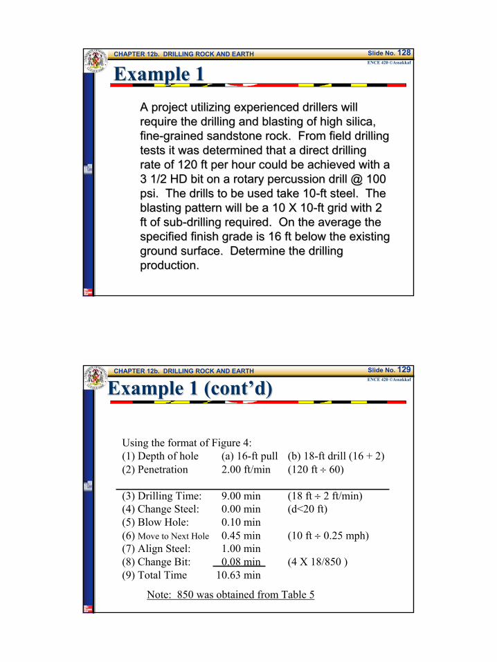
Example 1Example 1A project utilizing experienced drillers will A project utilizing experienced drillers will require the drilling and blasting of high silica, require the drilling and blasting of high silica, finefine--grained sandstone rock. From field drilling grained sandstone rock. From field drilling tests it was determined that a direct drilling tests it was determined that a direct drilling rate of 120 ft per hour could be achieved with a rate of 120 ft per hour could be achieved with a 3 1/2 HD bit on a rotary percussion drill @ 100 3 1/2 HD bit on a rotary percussion drill @ 100 psipsi. The drills to be used take 10. The drills to be used take 10--ft steel. The ft steel. The blasting pattern will be a 10 X 10blasting pattern will be a 10 X 10--ft grid with 2 ft grid with 2 ft of subft of sub--drilling required. On the average the drilling required. On the average the specified finish grade is 16 ft below the existing specified finish grade is 16 ft below the existing ground surface. Determine the drilling ground surface. Determine the drilling production.production.
CHAPTER 12b. DRILLING ROCK AND EARTHENCE 420 ©Assakkaf
Slide No. 129
Example 1 (cont’d)Example 1 (cont’d)
Using the format of Figure 4:(1) Depth of hole (a) 16-ft pull (b) 18-ft drill (16 + 2)(2) Penetration 2.00 ft/min (120 ft ÷ 60)
(3) Drilling Time: 9.00 min (18 ft ÷ 2 ft/min)(4) Change Steel: 0.00 min (d<20 ft)(5) Blow Hole: 0.10 min(6) Move to Next Hole 0.45 min (10 ft ÷ 0.25 mph)(7) Align Steel: 1.00 min(8) Change Bit: 0.08 min (4 X 18/850 )(9) Total Time 10.63 min
Note: 850 was obtained from Table 5

30
CHAPTER 12b. DRILLING ROCK AND EARTHENCE 420 ©Assakkaf
Slide No. 130
Example 1 (cont’d)Example 1 (cont’d)
Table 5 (Table 12-6c, Text)
CHAPTER 12b. DRILLING ROCK AND EARTHENCE 420 ©Assakkaf
Slide No. 131
Example 1 (cont’d)Example 1 (cont’d)
(10) Operating Rate: 1.69 ft/min (18 ÷ 10.63)
(11) Production Efficiency.: 50 min/hr
(12) Hourly Production 84.5 ft/hr (50 × 1.55)
31
CHAPTER 12b. DRILLING ROCK AND EARTHENCE 420 ©Assakkaf
Slide No. 132
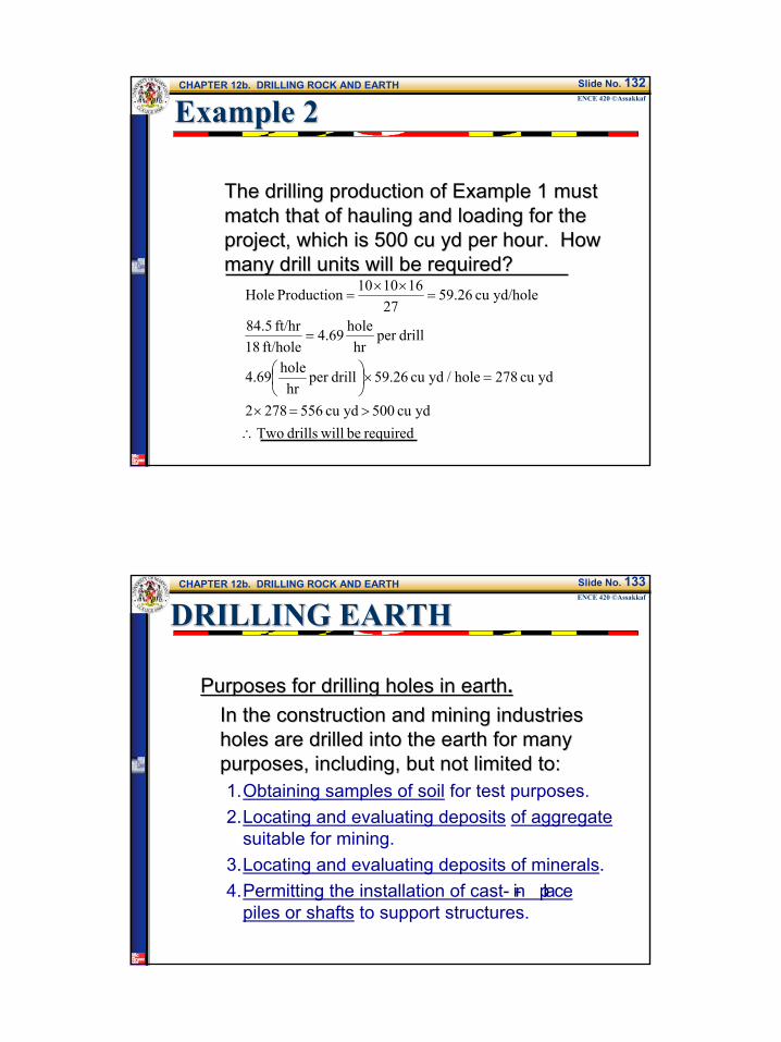
Example 2Example 2
The drilling production of Example 1 must The drilling production of Example 1 must match that of hauling and loading for the match that of hauling and loading for the project, which is 500 cu yd per hour. How project, which is 500 cu yd per hour. How many drill units will be required?many drill units will be required?
required be willdrills Two ydcu 500 ydcu 556 2782
ydcu 278hole / ydcu 59.26drillper hr
hole4.69
drillper hr
hole69.4ft/hole 18
ft/hr 5.84
yd/holecu 26.5927
1610 10 Production Hole
∴>=×
=×
=
=××
=
CHAPTER 12b. DRILLING ROCK AND EARTHENCE 420 ©Assakkaf
Slide No. 133
DRILLING EARTHDRILLING EARTH
Purposes for drilling holes in earthPurposes for drilling holes in earth..In the construction and mining industries In the construction and mining industries holes are drilled into the earth for many holes are drilled into the earth for many purposes, including, but not limited to:purposes, including, but not limited to:1.Obtaining samples of soil for test purposes.2.Locating and evaluating deposits of aggregate
suitable for mining.3.Locating and evaluating deposits of minerals.4.Permitting the installation of cast- in- place
piles or shafts to support structures.

32
CHAPTER 12b. DRILLING ROCK AND EARTHENCE 420 ©Assakkaf
Slide No. 134
DRILLING EARTHDRILLING EARTH
5. Enabling the driving of load-bearing piles into hard and tough formations.
6. Providing wells for supplies of water or for deep drainage purposes.
7. Providing shafts for ventilating mines, tunnels, and other underground facilities.
8. Providing horizontal holes through embankments, such as those for the installation of utility conduits.