Embed Size (px)
Citation preview
CERTIFIED TECHNICIAN PROGRAM TRAINING MANUAL
Construction Procedures Part I
Revised 2016

This material is to be used for training purposes only. Some of the procedures, field tests, and other operating procedures as described within these pages may be different than actual on-site procedures. Therefore, application should not be made without consideration of specific circumstances and current INDOT standards and policies.
Table of Contents Chapter One -- Introduction General Definitions .................................................................................................... 1-1 Area Definitions ......................................................................................................... 1-3 Accuracy of Calculations ........................................................................................... 1-6 Rounding Degree of Accuracy Exceptions Chapter Two -- Use and Care of Level Definitions.................................................................................................................. 2-1 Benchmark Level Circuit Turning Point Backsight Foresight Height of Instrument Optics Leveling Rod Targets Hand Level Two Peg Test ............................................................................................................. 2-4 Level Notes ................................................................................................................ 2-5 Level Set-Up Procedure ............................................................................................. 2-10 Care and Cleaning of the Level ................................................................................. 2-13 Profile Leveling ......................................................................................................... 2-13 Self-Leveling Level ................................................................................................... 2-16 Leveling Compensator Chapter Three -- The Field Book Instructions ................................................................................................................. 3-1 Summary .................................................................................................................... 3-3 Chapter Four -- Distance Measurements Pacing ......................................................................................................................... 4-1 Tape............................................................................................................................ 4-1

Equipment .................................................................................................................. 4-2 Tapes Markers Range Poles Plumb Bobs Hand Level Procedure ................................................................................................................... 4-5 Taping Over Smooth, Level Ground Taping Over Hilly, Sloping Ground Taping Error Chapter Five -- Cross Sections Side Slopes ................................................................................................................. 5-2 Field Notes ................................................................................................................. 5-3 Original Cross Sections.............................................................................................. 5-3 Profiles ....................................................................................................................... 5-6 Vertical Sections ........................................................................................................ 5-6 Zero Section ............................................................................................................... 5-7 Split Section ............................................................................................................... 5-7 Match Lines ............................................................................................................... 5-7 Interpolation ............................................................................................................... 5-8 Earthwork Quantities ................................................................................................. 5-10 Chapter Six -- Slope Stakes Definitions.................................................................................................................. 6-1 Control Point Grade Rod Ground Rod Reading Slope Stakes ................................................................................................. 6-3 Setting Slope Stakes ................................................................................................... 6-4 Field Procedure Chapter Seven -- Radius Layout Layouts for Square Drives/Approaches ..................................................................... 7-1 Layouts for Skew Drives/Approaches ....................................................................... 7-4 Chapter Eight -- Turn Lanes Driveways .................................................................................................................. 8-1 Mailbox Approaches .................................................................................................. 8-2

Chapter Nine -- Pipe Structures Pipe Types .................................................................................................................. 9-1 Pipe End Treatments .................................................................................................. 9-2 Pipe End Section Grated Box End Section Structure Order........................................................................................................... 9-3 Pipe Order Cross-Section View Computing Structure Length Using Elbows Structure Field Layout ............................................................................................... 9-9 Staking Structures Normal Layout Laser Layout Checking Grade Batterboard and Stringline Laser Grade Control Basis of Use for Pipe Materials ................................................................................. 9-11 Metal Pipe Concrete Pipe Plastic Pipe Metal Pipe End Safety Metal End Section Other Items Recording Tags for Basis of Use Multi-Plate Pipe Miscellaneous Concrete Recording Tags for Future Use Chapter Ten -- Pipe Placement Excavation.................................................................................................................. 10-1 Rock Excavation Unsuitable Material Excess Excavation Payment Removal of Existing Structures Safety Laying Pipe ................................................................................................................ 10-3 Structure Bearing Laying Concrete or Clay Bell Pipe ABS Pipe Metal Pipe Multi-Plate Pipe Joining Pipe ............................................................................................................................ 10-4 Joining Pipe with Collars
Stub-Tee Connections ................................................................................................ 10-4 Metal Pipe Concrete Pipe Pipe End Treatments .................................................................................................. 10-5 Pipe Anchors Pipe End Sections Grated Box End Sections and Safety Metal End Sections Chapter Eleven -- Measurement of Pipe Items Pipe Measurement ...................................................................................................... 11-1 Tees, Stub-Tees, and Wyes ........................................................................................ 11-1 Elbows........................................................................................................................ 11-1 Others Connections .................................................................................................... 11-1 Anchors ...................................................................................................................... 11-1 Pipe End Sections and Safety Metal End Sections .................................................... 11-1 Grated Box End Sections ........................................................................................... 11-1 Chapter Twelve -- Manholes, Inlets, and Catch Basins Structure............. ........................................................................................................ 12-1 Methods of Construction............................................................................................ 12-1 Material Requirements ............................................................................................... 12-1 Concrete Brick or Block Structures in Pavement Area ...................................................................................... 12-2 Hoods for Catch Basins ............................................................................................. 12-2 Mortar Mixture........................................................................................................... 12-2 Precast Structure Openings ........................................................................................ 12-3 Structure Joints........................................................................................................... 12-3 Adjustments ............................................................................................................... 12-3 Grade Adjustment to Existing Structures .................................................................. 12-3 Adjusting Existing Structures Replacing Castings Reconstructed Structures Castings in Pavement Area Adjustment on Resurface Contracts Manhole, Inlets, and Catch Basins ............................................................................. 12-4 Basis of Payment Miscellaneous Requirements Chapter Thirteen -- Pipe and Structure Backfill Backfill Limits ........................................................................................................... 13-1 Basis of Use ............................................................................................................... 13-1 Backfill Methods ........................................................................................................ 13-1
Trench Details ............................................................................................................ 13-2 Rock ........................................................................................................................... 13-2 Bedding Details .......................................................................................................... 13-2 Backfill Placement ..................................................................................................... 13-2 Method 1 Backfill Method 2 Backfill Other Backfill Outside Backfill Specified Limits Cover Limits .............................................................................................................. 13-3 Ramps over Structure for Protection Limitations ................................................................................................................. 13-4 Payment for Backfill .................................................................................................. 13-4 Structure Backfill Flowable Backfill Example Problem Chapter Fourteen -- Relining Existing Pipe Structures Slip Lining Roadway Culverts with Polyethylene Culvert Pipe ................................ 14-1 Materials Equipment Right of Entries Construction Requirements Jacked Pipe................................................................................................................. 14-5 Construction Requirements Jacking Boring Jacking Steel Pipe Jacking Concrete Pipe Chapter Fifteen – Calculating Pipe Lengths Example Problem ....................................................................................................... 15-1 Skew Pipes ................................................................................................................. 15-4 Chapter Sixteen -- Multi-Plate Pipe Plates .......................................................................................................................... 16-1 Bolts ........................................................................................................................... 16-2 Plate Identification and Location ............................................................................... 16-4 Pipe - Arch Assembly ................................................................................................ 16-6 Bolting........................................................................................................................ 16-7


1 Introduction General Definitions Area Definitions Accuracy of Calculations Rounding Degree of Accuracy Table Exceptions
1-1
CHAPTER ONE: INTRODUCTION
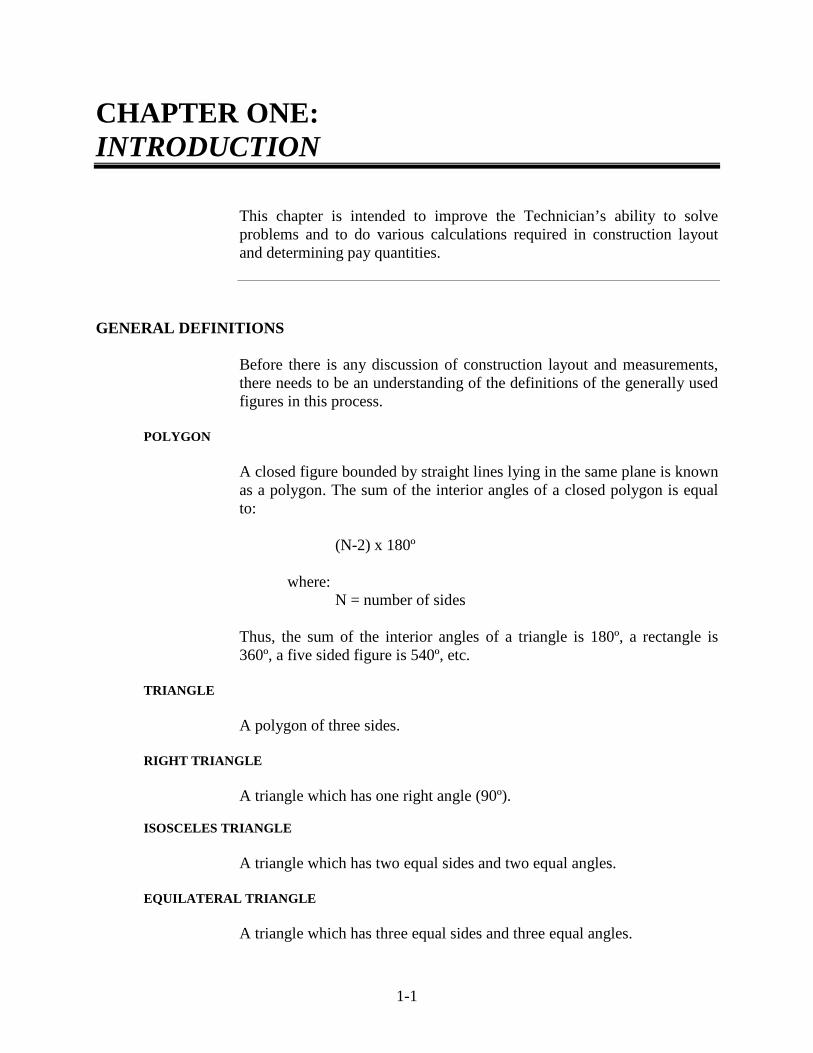
This chapter is intended to improve the Technician’s ability to solve problems and to do various calculations required in construction layout and determining pay quantities.
GENERAL DEFINITIONS
Before there is any discussion of construction layout and measurements, there needs to be an understanding of the definitions of the generally used figures in this process.
POLYGON
A closed figure bounded by straight lines lying in the same plane is known as a polygon. The sum of the interior angles of a closed polygon is equal to:
(N-2) x 180º where: N = number of sides
Thus, the sum of the interior angles of a triangle is 180º, a rectangle is 360º, a five sided figure is 540º, etc.
TRIANGLE
A polygon of three sides.
RIGHT TRIANGLE
A triangle which has one right angle (90º).
ISOSCELES TRIANGLE
A triangle which has two equal sides and two equal angles.
EQUILATERAL TRIANGLE
A triangle which has three equal sides and three equal angles.

1-2
OBLIQUE TRIANGLE
A triangle which has no right angle and no two sides are equal.
CONGRUENT TRIANGLES
Two triangles are congruent if their corresponding sides and corresponding angles are equal.
SIMILAR TRIANGLES
Two triangles are similar if their corresponding angles are equal and their corresponding sides are proportional.
RECTANGLE
A rectangle is a four-sided polygon whose angles are right angles. A square is a rectangle whose four sides are equal.
PERIMETER
The boundary (outer limits) of a closed area. TRAPEZOID
A four-sided polygon which has two parallel sides and two non-parallel sides.
CIRCLE
A closed plane curve, all points of which are equidistant from a point called the center.
RADIUS
The distance from the center of the circle to any point on the circle.
DIAMETER
The distance across the circle through the center. CHORD
A straight line between two points on a circle. ARC
Any part of the circle.

1-3
SEMI-CIRCLE
An arc equal to one half the circumference of a circle. AREA DEFINITIONS
Area is the surface within a set of lines. Area is measured in square units, square inches, square feet, square miles, etc.
RECTANGLE
The area of a rectangle is equal to the product of the length and the width.
A = L x W where:
L = length of rectangle W = width of rectangle
TRIANGLE
The area of a triangle is expressed in terms of its base and altitude. Any side of a triangle may be called the base. The altitude is the perpendicular distance from the base to the vertex opposing the base. (An angle may be defined as the space between two lines diverging from a common point. This point is called the vertex.) The area of any triangle is:
A = ½ B x H where:
B = base length H = altitude length
RIGHT TRIANGLE
The area of a right triangle is equal to one half the product of the base and the altitude.
AREA OF A TRIANGLE WITH KNOWN SIDES
If the length of the three sides of a triangle are known, the area may be calculated from:
A = \/ s (s-a) (s-b) (s-c)
where:
A = area
L
c
b a
H
B
W
1-4
s = ½ perimeter length a,b,c = lengths of each of the sides
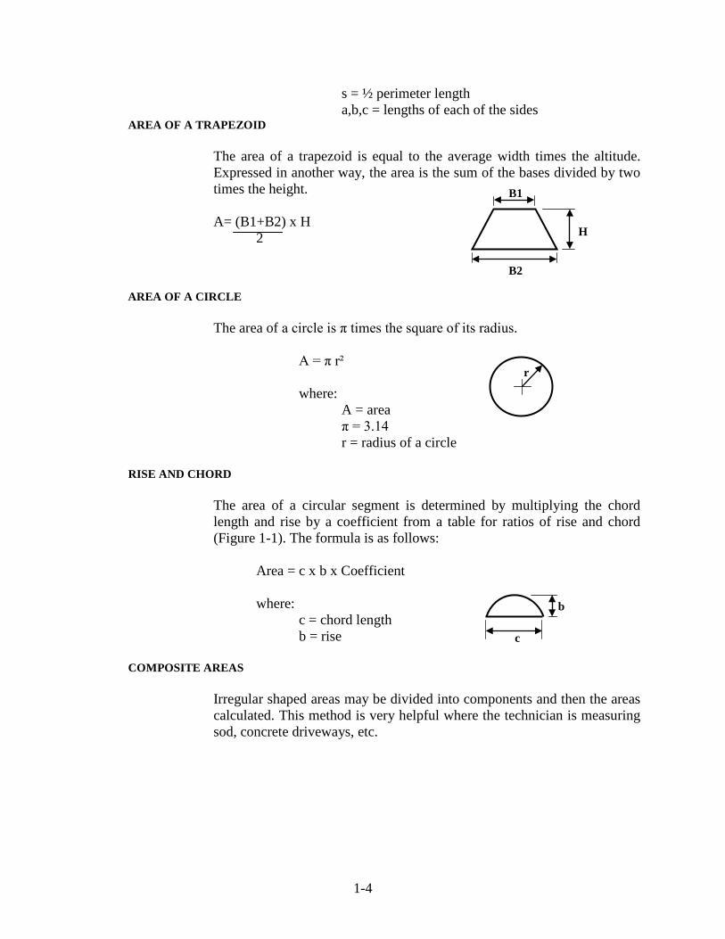
AREA OF A TRAPEZOID
The area of a trapezoid is equal to the average width times the altitude. Expressed in another way, the area is the sum of the bases divided by two times the height. A= (B1+B2) x H 2
AREA OF A CIRCLE
The area of a circle is π times the square of its radius.
A = π r² where: A = area π = 3.14 r = radius of a circle
RISE AND CHORD
The area of a circular segment is determined by multiplying the chord length and rise by a coefficient from a table for ratios of rise and chord (Figure 1-1). The formula is as follows:
Area = c x b x Coefficient where:
c = chord length b = rise
COMPOSITE AREAS
Irregular shaped areas may be divided into components and then the areas calculated. This method is very helpful where the technician is measuring sod, concrete driveways, etc.
r
c
b
H
B2
B1

1-5
AREA OF CIRCULAR SEGMENTS
Coefficient is given opposite the quotient of b divided by C Area = C x b x Coefficient
Aº Coefficient b C
Aº Coefficient b C
Aº Coefficient b C
Aº Coefficient b C
1 .6667 .0022 46 .6722 .1017 91 .6895 .2097 136 .7239 .3373 2 .6667 .0044 47 .6724 .1040 92 .6901 .2122 137 .7249 .3404 3 .6667 .0066 48 .6727 .1063 93 .6906 .2148 138 .7260 .3436 4 .6667 .0087 49 .6729 .1086 94 .6912 .2174 139 .7270 .3469 5 .6667 .0109 50 .6732 .1109 95 .6918 .2200 140 .7281 .3501 6 .6667 .0131 51 .6734 .1131 96 .6924 .2226 141 .7292 .3534 7 .6668 .0153 52 .6737 .1154 97 .6930 .2252 142 .7303 .3567 8 .6668 .0175 53 .6740 .1177 98 .6936 .2279 143 .7314 .3600 9 .6669 .0197 54 .6743 .1200 99 .6942 .2305 144 .7325 .3633 10 .6670 .0215 55 .6746 .1224 100 .6948 .2332 145 .7336 .3666 11 .6670 .0240 56 .6749 .1247 101 .6954 .2358 146 .7348 .3700 12 .6671 .0262 57 .6752 .1270 102 .6961 .2385 147 .7360 .3734 13 .6672 .0284 58 .6755 .1293 103 .6967 .2412 148 .7372 .3768 14 .6672 .0306 59 .6758 .1316 104 .6974 .2439 149 .7384 .3802 15 .6673 .0328 60 .6761 .1340 105 .6980 .2466 150 .7396 .3837 16 .6674 .0350 61 .6764 .1363 106 .6987 .2493 151 .7408 .3871 17 .6674 .0372 62 .6768 .1387 107 .6994 .2520 152 .7421 .3906 18 .6675 .0394 63 .6771 .1410 108 .7001 .2548 153 .7434 .3942 19 .6676 .0416 64 .6775 .1434 109 .7008 .2575 154 .7447 .3977 20 .6677 .0437 65 .6779 .1457 110 .7015 .2603 155 .7460 .4013 21 .6678 .0459 66 .6782 .1481 111 .7022 .2631 156 .7473 .4049 22 .6679 .0481 67 .6786 .1505 112 .7030 .2659 157 .7486 .4085 23 .6680 .0504 68 .6790 .1529 113 .7037 .2687 158 .7500 .4122 24 .6681 .0526 69 .6794 .1553 114 .7045 .2715 159 .7514 .4159 25 .6682 .0548 70 .6797 .1577 115 .7052 .2743 160 .7528 .4196 26 .6684 .0570 71 .6801 .1601 116 .7060 .2772 161 .7542 .4233 27 .6685 .0592 72 .6805 .1625 117 .7068 .2800 162 .7557 .4270 28 .6687 .0614 73 .6809 .1649 118 .7076 .2829 163 .7571 .4308 29 .6688 .0636 74 .6814 .1673 119 .7084 .2858 164 .7586 .4346 30 .6690 .0658 75 .6818 .1697 120 .7092 .2887 165 .7601 .4385 31 .6691 .0681 76 .6822 .1722 121 .7100 .2916 166 .7616 .4424 32 .6693 .0703 77 .6826 .1746 122 .7109 .2945 167 .7632 .4463 33 .6694 .0725 75 .6831 .1771 123 .7117 .2975 168 .7648 .4502 34 .6696 .0747 79 .6835 .1795 124 .7126 .3004 169 .7664 .4542 35 .6698 .0770 80 .6840 .1820 125 .7134 .3034 170 .7680 .4582 36 .6700 .0792 81 .6844 .1845 126 .7143 .3064 171 .7696 .4622 37 .6702 .0814 82 .6849 .1869 127 .7152 .3094 172 .7712 .4663 38 .6704 .0837 83 .6854 .1894 128 .7161 .3124 173 .7729 .4704 39 .6706 .0859 84 .6859 .1919 129 .7170 .3155 174 .7746 .4745 40 .6708 .0882 85 .6864 .1944 130 .7180 .3185 175 .7763 .4787 41 .6710 .0904 86 .6869 .1970 131 .7189 .3216 176 .7781 .4828 42 .6712 .0927 87 .6874 .1995 132 .7199 .3247 177 .7799 .4871 43 .6714 .0949 88 .6879 .2020 133 .7209 .3278 178 .7817 .4914 44 .6717 .0972 89 .6884 .2046 134 .7219 .3309 179 .7835 .4957 45 .6719 .0995 90 .6890 .2071 135 .7229 .3341 180 .7854 .5000
Figure 1-1. Table for Ratios of Rise and Chord

1-6
ACCURACY OF CALCULATIONS ROUNDING When calculations are conducted, rounding is required to be in accordance
with Section 109.01(a) using the standard "5" up procedure. There are two rules for rounding numbers:
1. When the first digit discarded is less than 5, the last digit
retained should not be changed.
Examples: 2.4 becomes 2 2.43 becomes 2.4 2.434 becomes 2.43 2.4341 becomes 2.434
2. When the first digit discarded is 5 or greater, the last digit
retained should be increased by one unit.
Examples: 2.6 becomes 3 2.56 becomes 2.6 2.416 becomes 2.42 2.4157 becomes 2.416
DEGREE OF ACCURACY
The degree of accuracy is based on the dollar value of the bid item. All measurements are made to the nearest first decimal place (0.1). Calculations and final pay quantities are shown in the following table:
A unit as shown in this table is the proposal unit.
Unit Price Bid Amount
Field Measurements
Calculations & Sub Totals
Final Pay Quantity
$ 0 -9.99 0.1 unit 0.1 unit 1 unit $ 10 – 99.9 0.1 unit 0.01 unit 0.1 unit $ 100 – 999 0.1 unit 0.01 unit 0.01 unit $ 1000 & above 0.1 unit 0.001 unit 0.001 unit
1-7
EXCEPTIONS
Weigh tickets are considered original notes for many items and are required to be measured to the nearest 100 pounds. Pavement striping and pipe (except concrete pipe) is measured and calculated to the nearest one foot. The Specifications for concrete pipe should be checked to determine the measurement units. Seed is weighed to the nearest one pound. Fertilizer is weighed to the nearest one hundredth ton or 10 pounds. Items whose proposal unit is listed as "each" or "lump sum" are measured or counted to that whole unit. Linear grading is field measured to the nearest 0.001% of the unit, with calculations, sub totals, and final pay quantities as shown in the accuracy table. Field measurements, calculations, sub totals and final pay quantity on herbicide contracts are made to the nearest one unit.

2 Use and Care of Level Definitions Benchmark Level Circuit Turning Point Backsight Foresight Height of Instrument Optics Leveling Rod Targets Hand Level Two Peg Test Level Notes Level Set-Up Procedure Care and Cleaning of the Level Profile Leveling Self-Leveling Level Leveling Compensator

2-1
CHAPTER TWO: USE AND CARE OF LEVEL
The level is a precision instrument used in surveying to determine and establish elevations of points and differences in elevation between points. There are many types of leveling devices used for this purpose and there are many methods and procedures which may be used to establish elevations. In highway surveying, leveling is done to provide the necessary vertical control to construct a highway or a bridge. A point of vertical control is known as an elevation. Sometimes in paving or in roadwork an elevation is referred to as a grade. All elevations are related to some reference. Generally, this reference is sea-level so that a point having an elevation of 722.95 ft means that the particular point is 722.95 ft above sea-level. Differential leveling is the operation of determining the elevations of points some distance apart. This is the method used in highway surveying to establish the necessary vertical control for construction. Usually this procedure is done by direct leveling. Differential leveling requires a series of set-ups of the instrument along the general route. For each set-up, a rod-reading back to a point of known elevation and then forward to a point of unknown elevation is taken. The difference in value between the two readings is understood to be the “grade change” or “elevation change” between the two points.
DEFINITIONS
BENCHMARK
A benchmark (B.M.) is a definite point on a permanent object which has a known elevation and a known location. Temporary benchmarks, (T.B.M.) are used many times to supplement permanent benchmarks. The elevation and location of these points are also known but not intended to be permanent. A benchmark is a point of reference which is convenient for leveling in a given locality.

2-2
LEVEL CIRCUIT
Once the elevation of a point is determined, that point can be used for determining the elevations of other points by means of a closed transverse. The relation to sea-level is very precise and obtained by running a level circuit such that the elevation of the beginning and the end of the circuit are known and tied together.
TURNING POINT
A turning point (T.P.) is an intermediate point between benchmarks which provides a temporary point of known elevation for a level circuit between two benchmarks a long distance apart. A turning point may be an iron pin or wooden hub which is driven firmly into the ground at a convenient location. A turning point may be an existing convenient object upon which a rod reading may be taken; however, the object is required to be solid, stable, and not move or change in elevation for the few minutes needed between set-ups. A permanent or temporary benchmark may be used as a turning point. Rod readings are taken on the pin before an instrument is advanced and again as the initial rod readings are taken before the instrument has been re-established ahead on the circuit. After the second reading, the pin or hub is pulled and carried ahead.
BACKSIGHT
A backsight (B.S.) is a rod reading taken at a point of known elevation, such as a benchmark or turning point. Another term for backsight is a “plus sight”.
FORESIGHT
A foresight (F.S.) is a rod reading taken on a point for which the elevation is unknown and will be established. Another term for foresight is sometimes called a “minus sight”.
HEIGHT OF INSTRUMENT
The height of instrument (H.I.) is the elevation of the line of sight of the center of the horizontal cross-hairs in the telescope when the instrument is properly leveled. In other words, level plane of sight is known as the height of the instrument. The height of instrument is equal to the elevation of the benchmark sighted plus the rod reading taken on the benchmark. In mathematical terms this may be written as follows:
H.I. = (elevation B.M.) + B.S.

2-3
OPTICS
The important features of the instrument telescope are the optical properties as follows:
1. Illumination -- this refers to how well lighted the image
appears. 2. Definition -- this refers to the sharpness of detail.
3. Width of field of view -- this is expressed as an angle and
indicates how much of the object is visible at one time. 4. Magnifying power -- this is the ratio of the apparent lineal
dimensions of the object and of the image.
The level most used by INDOT is the self leveling type. (see page 2-16) Another type of level that may still be used by INDOT is the Dumpy level (see figure 2-5) operation of the level is explained later in this manual. Note: The precision of the work done with this type of instrument(s) is excellent to approximately 200 ft.
LEVELING ROD
The second most important piece of equipment needed for differential leveling is the leveling rod. Several types of leveling rods are used in highway construction. The Chicago Rod and the Philadelphia Rod are the two types which are generally preferred. The Chicago Rod is a slip-joint rod which has a total length of 12 ½ ft when all sections are used. The Philadelphia Rod is a sliding joint type of rod that extends to 15 or 16 ft and is a more convenient rod when using a target. Selection of a rod type is a matter of personal preference or availability.
TARGETS
An accessory which may be used with a rod when doing more precise work is a target. The target is fitted with a built-in vernier so that rod readings may be obtained to one-thousandth of a foot. Targets are rarely used for highway surveying, although they may be used when precise readings for certain bridge structures are required. The design of the structure or conditions which exist adjacent to the structure during construction may require these precise readings.

2-4
HAND LEVEL The level and the leveling rod are the only two pieces of equipment that a crew is required to have to run a precise and complete level circuit. Other items of minor equipment are needed for specific types of leveling. A very handy device which is used for checking slopes and setting slope stakes is the hand level. The hand level is simply a small telescope which has a built in level bubble. The bubble is small and therefore poor for precise work. There is very little magnification built into this device. Because the optical properties of illumination, magnification, definition, and width of field of view are not available, the hand level is never used for precise work. The device is used only as a convenience for short sightings or approximate sightings accurate to the nearest one tenth of a foot.
TWO PEG TEST
The two peg test is a very simple test which is used in the field to determine if the line of sight of the telescope is exactly parallel to the bubble tube. This is one of the most important properties of a level and is required to be checked periodically. The steps below are required to be followed to check this adjustment in a level.
1) Set two hubs 300 ft apart. The location is selected so that
the tops of the hubs are obviously different in elevation.
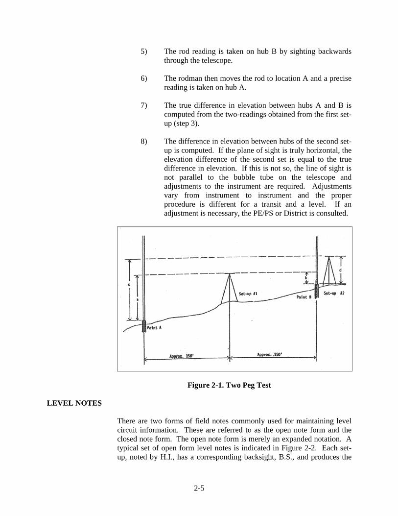
2) Set up the level half way between the two hubs and level the instrument properly. Figure 2-1 illustrates a sketch of the level properly established between the two hubs represented by points A and B.
3) The rodman sets the rod on hub A and rocks the rod on this
point. The instrument operator reads the rod, making sure that the rod is at the center of the cross hairs and that the level bubble is truly centered when the reading is taken. The rodman moves up to and sets the rod on hub B. The rodman then rocks the rod as the instrument operator turns the instrument to obtain a precise reading of the rod at hub B. Once again, the bubble level is centered when the reading is taken. This is the first set-up.
4) The level is then moved to the highest location, in this case
hub B, and set so that the eye piece of the level is just a few inches from the rod when the level rod is plumbed on the hub.
2-5
5) The rod reading is taken on hub B by sighting backwards through the telescope.
6) The rodman then moves the rod to location A and a precise
reading is taken on hub A.
7) The true difference in elevation between hubs A and B is computed from the two-readings obtained from the first set-up (step 3).
8) The difference in elevation between hubs of the second set-
up is computed. If the plane of sight is truly horizontal, the elevation difference of the second set is equal to the true difference in elevation. If this is not so, the line of sight is not parallel to the bubble tube on the telescope and adjustments to the instrument are required. Adjustments vary from instrument to instrument and the proper procedure is different for a transit and a level. If an adjustment is necessary, the PE/PS or District is consulted.
Figure 2-1. Two Peg Test LEVEL NOTES
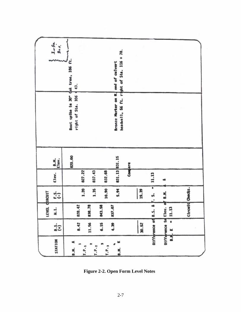
There are two forms of field notes commonly used for maintaining level circuit information. These are referred to as the open note form and the closed note form. The open note form is merely an expanded notation. A typical set of open form level notes is indicated in Figure 2-2. Each set-up, noted by H.I., has a corresponding backsight, B.S., and produces the

2-6
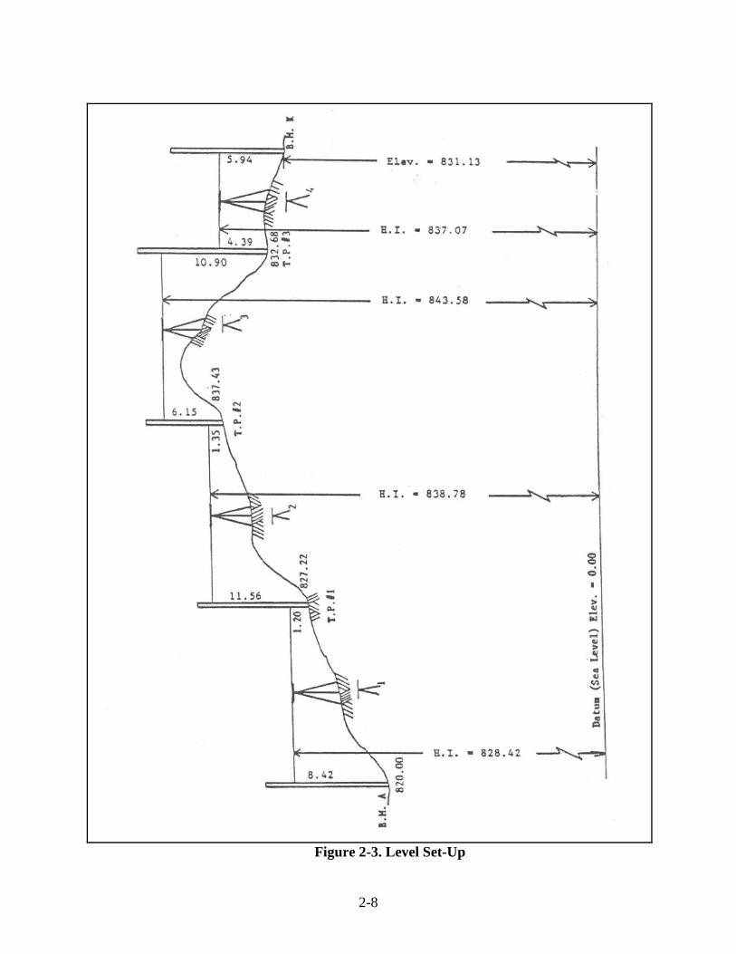
H.I. Each turning point, T.P., is defined by a foresight, F.S., and an elevation. The numbers used in the open note form of Figure 2-2 are indicated in Figure 2-3. This is an example of differential leveling and traces the work done to progress from benchmark A to benchmark K. The elevation of benchmark A is established as 820.00. The level is set up at the location marked I and the rod reading on benchmark A is 8.42. This rod reading is called the back sight or the plus sight, and is abbreviated as B.S. or (+). The back sight is a rod reading taken on the A point known elevation and used to determine the height of instrument. For the example indicated, the H.I. equals the elevation of benchmark A plus the back sight reading.
H.I. = 820.00 + 8.42 = 828.42
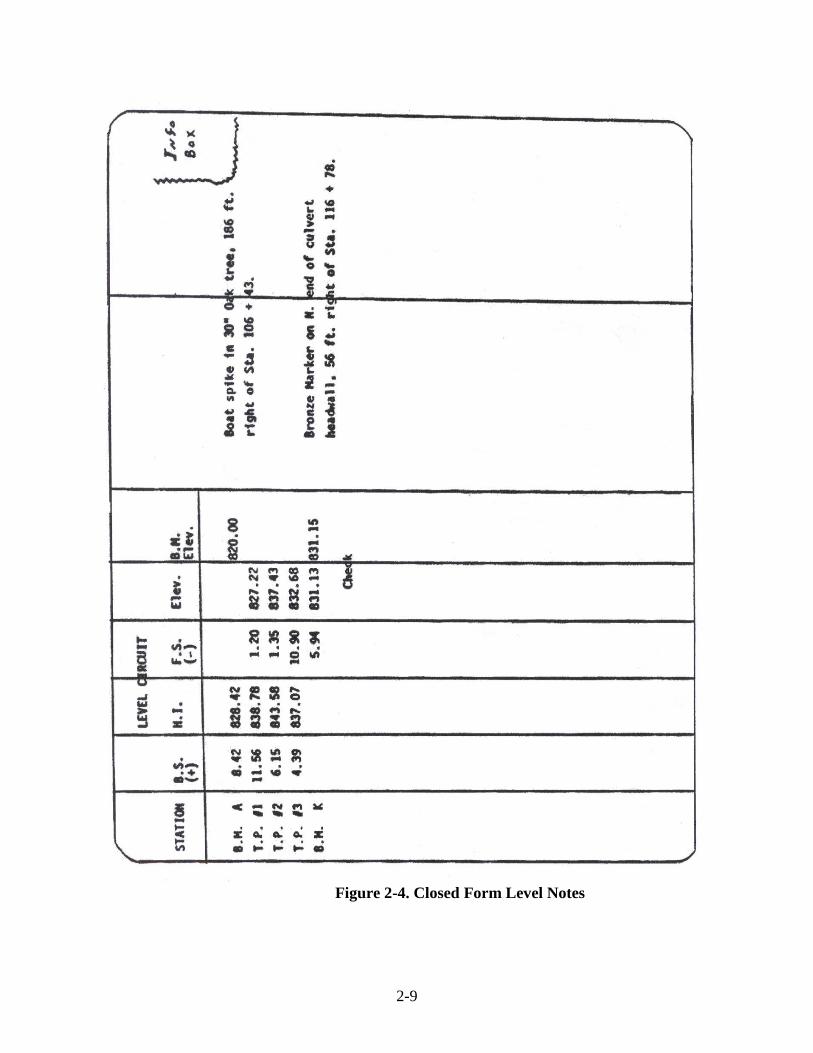
This value is recorded in the H.I. column of the notes as the H.I. of set-up number one. After the rod reading on A has been taken, T.P. #1 (turning point number one) is selected so the distance from benchmark A to the instrument is approximately equal to the distance from benchmark A to T.P. #1. A level rod reading is then taken on the TP #1 and is called a foresight or minus sight, which is noted as F.S. or (-). The turning point is a conveniently located temporary benchmark so that the instrument may be moved ahead and a sight taken back on this point to provide a point of vertical reference. The rodman remains at the first turning point while the instrument operator moves the level is moved to set-up number two. A backsight reading is taken on the rod held at TP #1. The rod is moved to TP #2 for a foresight reading at another conveniently located point ahead so that the rod reading may be obtained on benchmark K. In the example shown in Figure 2-3, there are four set-ups and three turning points or intermediate temporary benchmarks. Using the same numbers and the same example, a set of closed form level notes may be developed as shown in Figure 2-4. The closed form eliminates the set-up line and doubles the information noted for each turning point.
2-7
Figure 2-2. Open Form Level Notes
2-8
Figure 2-3. Level Set-Up
2-9
Figure 2-4. Closed Form Level Notes
2-10
LEVEL SET-UP PROCEDURE
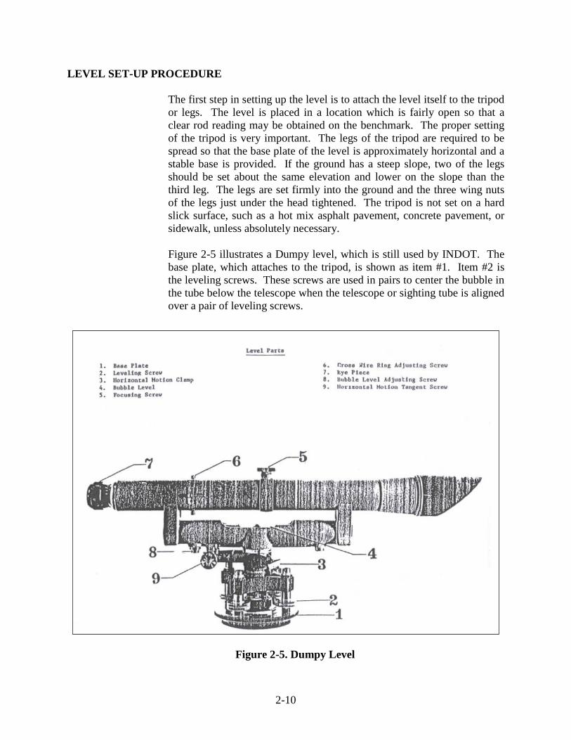
The first step in setting up the level is to attach the level itself to the tripod or legs. The level is placed in a location which is fairly open so that a clear rod reading may be obtained on the benchmark. The proper setting of the tripod is very important. The legs of the tripod are required to be spread so that the base plate of the level is approximately horizontal and a stable base is provided. If the ground has a steep slope, two of the legs should be set about the same elevation and lower on the slope than the third leg. The legs are set firmly into the ground and the three wing nuts of the legs just under the head tightened. The tripod is not set on a hard slick surface, such as a hot mix asphalt pavement, concrete pavement, or sidewalk, unless absolutely necessary. Figure 2-5 illustrates a Dumpy level, which is still used by INDOT. The base plate, which attaches to the tripod, is shown as item #1. Item #2 is the leveling screws. These screws are used in pairs to center the bubble in the tube below the telescope when the telescope or sighting tube is aligned over a pair of leveling screws.
Figure 2-5. Dumpy Level
2-11
To center the bubble, all four leveling screws are loosened uniformly and the telescope turned so that two leveling screws are directly under the telescope and the telescope is in line with the first sight to be taken. With the telescope directly over a pair of leveling screws, the bubble is brought to the center of the tube by loosening one screw while tightening the other with the thumb and first finger of each hand. In other words, when turning the leveling screws to level the instrument, your thumbs should either move toward each other or away from each other (depending on the direction you want the bubble to move). The bubble moves in the same direction as the left thumb. When the bubble becomes centered in the tube, the pair of leveling screws is tightened. Care is taken to not over tighten the screws. The telescope is then rotated 90° in either direction so that the telescope is directly over the other pair of leveling screws. The process is repeated to bring the bubble to the center of the tube. The telescope is turned back 90° so that the level is over the original pair of leveling screws. The bubble is checked to make sure that the level is centered. If the bubble is no longer centered, then the leveling screws are adjusted to bring the bubble to center and the telescope rotated back over the pair of leveling screws to check the bubble again. If the instrument is in good adjustment, the bubble remains centered. When the set-up is complete, the instrument operator is now ready to take the initial shot or backsight on the benchmarks or turning point, which is the starting point and point of known elevation for a level circuit. The telescope is rotated so that the benchmark may be sighted directly. Making sure the bottom of the rod is clean; the rodman sets the rod on the clean, that sections of the rod are set together properly, and that the rod is held right side up. The face of the rod is required to be facing the instrument. The rodman stands directly behind the rod with both hands on the sides of the rod so that no fingers are covering the face of the rod. By standing directly behind the rod, the rodman makes sure that the leveling rod is plumb. As the operator on the level sights through the instrument at the rod, the rodman begins to rock the rod toward the instrument and back to himself so that the rod is moved forward approximately 9 inches. and then directly away from the instrument the same amount. A slow, uniform rocking motion is applied by the rodman.
As the instrument operator sights through the level, the cross hairs are seen in his field of view. The level is turned so that the center of the cross-hairs is directly on the rod. The face of the rod appears to move up and down as the rodman rocks the rod. The numbers on the rod increase and then decrease to some minimum number, then increase again. The numbers continue increasing and decreasing as the rodman continues to rock the rod. The minimum number on the rod cut by the horizontal cross
2-12
hair is the rod reading on the benchmark. The instrument operator takes the reading; keep the number in mind, then looks to check that the bubble is exactly centered. If the bubble is not centered, the appropriate leveling screw is adjusted through the telescope again and another reading taken and recorded as the backsight. Items #5 and #7 indicated in Figure 2-5 are used to provide two adjustments that bring the rod into sharp focus, bring the cross hairs into sharp focus, and eliminate parallax. Parallax results when the optics are out of adjustment. The presence of parallax may be determined by nodding the head up and down while looking through the telescope. There is no movement of the image relative to the cross hairs. Movement indicates parallax is present and adjustment is needed. Item #3 of Figure 2-5 is the horizontal motion clamp which locks the telescope. Item #9 is the horizontal motion tangent screw which provides the fine adjustment so that the telescope may be turned a degree or so in either direction from the locked position by turning the knurled knob. The rod reading on the benchmark or turning point is recorded in the notes and when added to the elevation of the benchmark gives the elevation of the height of the instrument, H.I. This reading is the elevation of the plane, through the center of the telescope. The rodman moves ahead to the next point to be established, places the rod on the surface whose elevation is required, and begins to rock the rod as was previously done on the benchmark. The instrument operator rotates the telescope so that the rod is sighted with the center of the cross hairs then takes a reading. Since the elevation of the cross hairs is known, the rod reading on this point is subtracted from the H.I. and the elevation of the point is determined. There are three specific items to keep in mind so that the results of direct differential leveling are accurate, even though the instrument may be out of adjustment.
1. The bubble is centered before the final reading is obtained
and recorded. 2. The rod is sighted with the center of the cross hairs. 3. The backsight is balanced with the foresight. The distance
from the rod to the instrument, from the back and foresight, is required to be a maximum of 200 ft.

2-13
CARE AND CLEANING OF THE LEVEL
When the level is carried on the shoulder, the clamps are required to be tight enough to prevent wear, but loose enough so the level gives if accidentally bumped. When the level is carried inside a building, in dense growth, or anywhere there is a chance of being bumped, the level is carried under the arm with the instrument head in front of the carrier. The level is carefully set down. The cross hairs could be broken or the instrument jarred out of adjustment by harsh treatment. When being transported in a vehicle, the level is packed in the level case and placed in a location to minimize vibration. The leveling screws are not tightened too tight as this could cause warping of the plate. The level is never left unguarded. The tripod legs are spread and pushed into the ground to prevent the level being knocked down. The instrument is protected from rain by a waterproof cover. If a waterproof cover is not available, the dust cap is placed on the objective lens as soon as possible and the instrument taken inside. When brought inside, excess moisture is wiped off the instrument immediately and the instrument allowed to thoroughly dry before being placed in the case. Dust is removed with a camel hair brush, if available. The eye piece may be cleaned with alcohol and wiped with a soft cloth.
PROFILE LEVELING
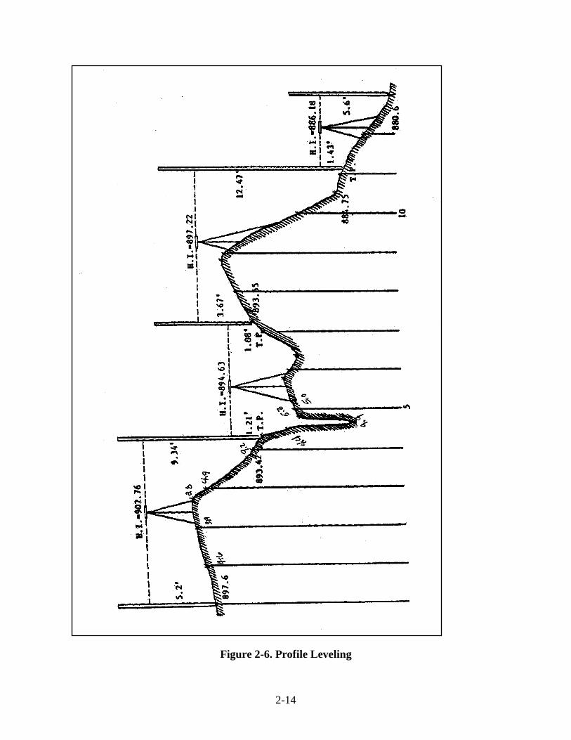
The purpose of profile leveling is to determine the elevations of the ground surface along some definite line. In INDOT work, the existing ground surface profile is required to be known to provide sufficient and necessary information for both design and construction. Profiles are plotted such that the vertical scale is exaggerated in relation to the horizontal scale so that the differences in the elevation are accentuated.
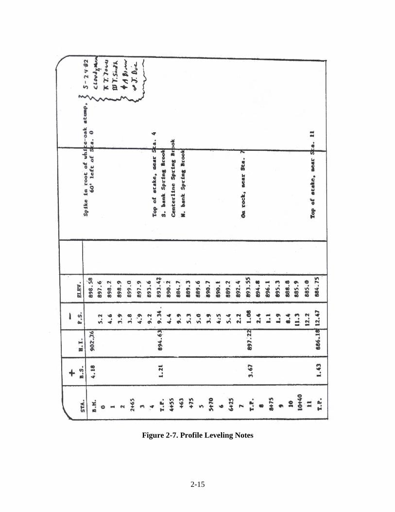
The line along which the profile is to be taken may be marked prior to the survey. This is normally done in 100 foot stations. A rod reading is taken at each full station and at each major break in the ground slope. This procedure differs from the running of a circuit level in that more foresights are taken from each set-up. The stations of the breaks in slope are taped and referenced from the full stations established along the profile line (Figure 2-6). A sample of a set of profile field notes is indicated in Figure 2-7. The turning points and benchmarks elevations are recorded to hundredths of a foot while the ground rod readings are recorded to tenths of a foot. Obtaining ground rod readings more precise than to tenths of a foot is not required.
2-14
Figure 2-6. Profile Leveling
2-15
Figure 2-7. Profile Leveling Notes
2-16
SELF- LEVELING LEVEL
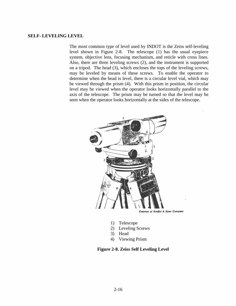
The most common type of level used by INDOT is the Zeiss self-leveling level shown in Figure 2-8. The telescope (1) has the usual eyepiece system, objective lens, focusing mechanism, and reticle with cross lines. Also, there are three leveling screws (2), and the instrument is supported on a tripod. The head (3), which encloses the tops of the leveling screws, may be leveled by means of these screws. To enable the operator to determine when the head is level, there is a circular level vial, which may be viewed through the prism (4). With this prism in position, the circular level may be viewed when the operator looks horizontally parallel to the axis of the telescope. The prism may be turned so that the level may be seen when the operator looks horizontally at the sides of the telescope.
Figure 2-8. Zeiss Self Leveling Level
1) Telescope 2) Leveling Screws 3) Head 4) Viewing Prism
2-17
LEVELING
The Zeiss level does not have a longitudinal spirit level to indicate when the telescope is level. None is needed. The head is approximately leveled by means of the leveling screws and the circular level. The line of sight is made exactly horizontal, with the telescope turned in any direction, by an automatic device called a compensator inside the telescope. Also, there is no clamp for preventing rotation of the telescope in a horizontal plane. An automatic coupling is used instead. To sight the telescope toward an object, such as a leveling rod, the telescope is rotated by hand so that the level points are in the proper direction. Then, either tangent screw is turned to make the fine adjustment.
COMPENSATOR
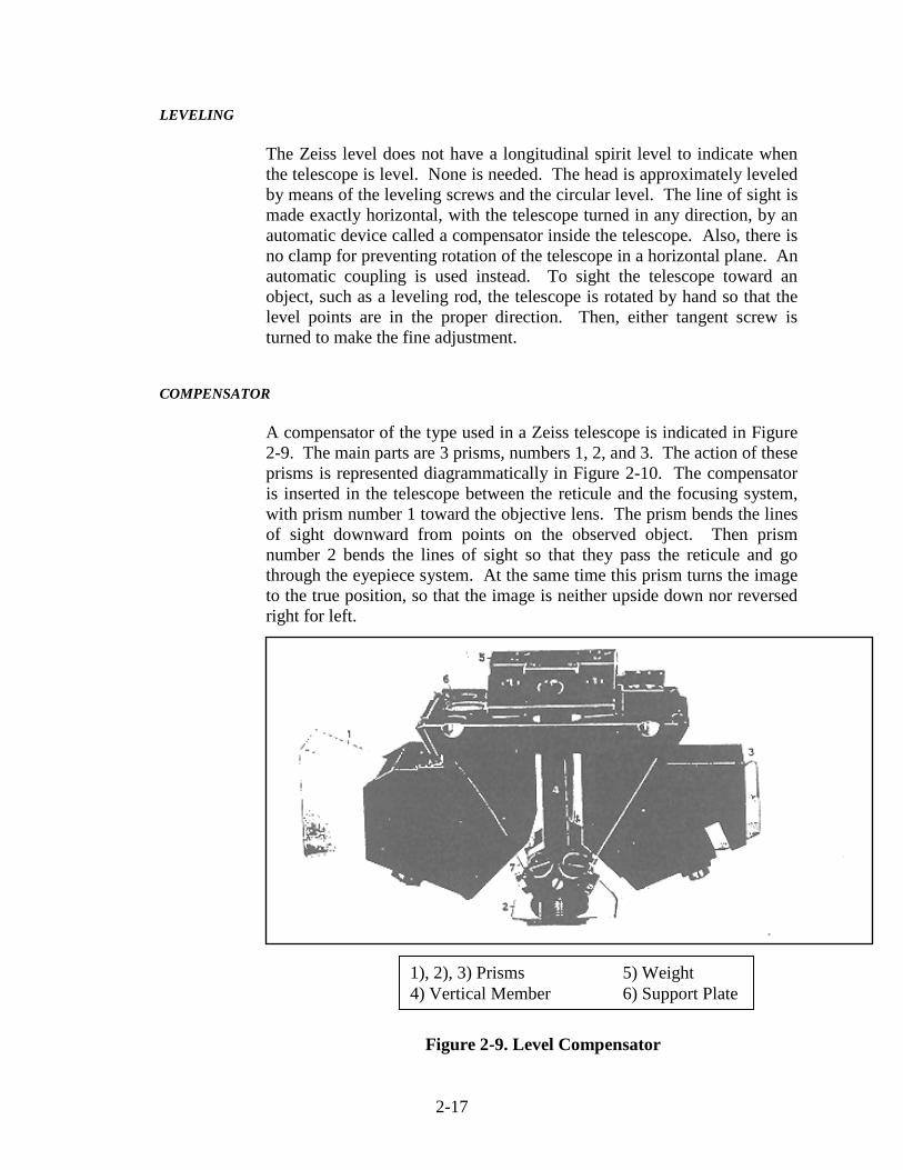
A compensator of the type used in a Zeiss telescope is indicated in Figure 2-9. The main parts are 3 prisms, numbers 1, 2, and 3. The action of these prisms is represented diagrammatically in Figure 2-10. The compensator is inserted in the telescope between the reticule and the focusing system, with prism number 1 toward the objective lens. The prism bends the lines of sight downward from points on the observed object. Then prism number 2 bends the lines of sight so that they pass the reticule and go through the eyepiece system. At the same time this prism turns the image to the true position, so that the image is neither upside down nor reversed right for left.
Figure 2-9. Level Compensator
1), 2), 3) Prisms 5) Weight 4) Vertical Member 6) Support Plate
2-18
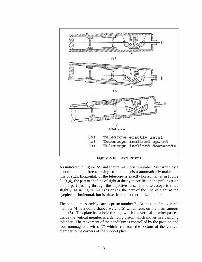
Figure 2-10. Level Prisms
As indicated in Figure 2-9 and Figure 2-10, prism number 2 is carried by a pendulum and is free to swing so that the prism automatically makes the line of sight horizontal. If the telescope is exactly horizontal, as in Figure 2-10 (a), the part of the line of sight at the eyepiece lies in the prolongation of the part passing through the objective lens. If the telescope is tilted slightly, as in Figure 2-10 (b) or (c), the part of the line of sight at the eyepiece is horizontal, but is offset from the other horizontal part. The pendulum assembly carries prism number 2. At the top of the vertical member (4) is a dome shaped weight (5) which rests on the main support plate (6). This plate has a hole through which the vertical member passes. Inside the vertical member is a damping piston which moves in a damping cylinder. The movement of the pendulum is controlled by the position and four nonmagnetic wires (7) which run from the bottom of the vertical member to the corners of the support plate.


3 Field Book Instructions Summary

3-1
CHAPTER THREE: FIELD BOOK
Field books contain valuable information which details and describes the layout, elevations, and quantities of features and materials incorporated in a construction contract. As such, they are part of the official and legal record of the work done. Field notes are required to be kept so that sufficient documentation of original data becomes part of the permanent contract record.
INSTRUCTIONS
Some of the common mistakes in field note keeping may be eliminated by observing the following points:
1) The outside cover of the field book always includes the
contract number, description number, book number, and the contents of the book.
2) The complete return address of the District is written on the
front flyleaf. 3) Each book is required to have an index. The first few
pages are reserved for this purpose. The index varies according to the contents of the book and revisions are added to the book as needed.
4) Information blocks are required to include, as a minimum,
the date, weather, and personnel conducting the work. 5) A system of lettering which may be easily read and clearly
understood is used. Small lettering is avoided. 6) 3H pencils or leads that does not smear are used. 7) Information is always recorded directly in the field book.
Data is not transcribed from scraps of paper. 8) A combination scale/protractor is used to help draw figures. 9) Sketches with proportions are carefully estimated. With
practice, a scale and protractor help to create sketches that are of a higher quality.

3-2
10) Details on sketches are exaggerated. 11) Sketches with tabulated data are lined up. 12) Left hand pages for tabulation of numerical data and right
hand pages for sketches are used. 13) Consideration is given to what the person in the office
needs to know and explanatory notes are made so all of the data is clear.
14) Conventional symbols are used. 15) A north arrow is placed at either the top or left side of the
page for all sketches indicated and should not overpower the sketch.
16) Tabulated figures are lined up with the column rulings and
digits and decimal points placed in line vertically. 17) All measurements and rod readings are checked to
determine if they are reasonable and accurate. 18) All values are repeated aloud before recording for
verification. 19) A zero is placed before all decimals if less than one. 20) The precision of measurements is indicated by recording
significant zeros. 21) Computation checks are made in the field and recorded
immediately. 22) All closures and ratios of error are recorded before leaving
the field. 23) Recorded data is not erased or written on top of. A line is
run through incorrect values and the correct value recorded near the incorrect value.
24) Diagonal lines from opposite corners are drawn if a page is
voided, and the word "VOID" written on the page. No information is obscured.
3-3
SUMMARY
Field books always contain the following data:
1) Title. 2) Return address. 3) Index.
4) Information concerning dates, weather, and personnel who
conducted the work.
Entries are not erased in the field books. If a mistake is made, the mistake is neatly crossed out and the proper data rewritten. A clear, descriptive sketch with references to known land marks or control points is always provided.
4 Distance Measurements Pacing Tape Equipment Tapes Markers Range Poles Plumb Bobs Hand Level Procedure Taping Over Smooth, Level Ground Taping Over Hilly, Sloping Ground Taping Error
4-1
CHAPTER FOUR: DISTANCE MEASUREMENTS
In surveying, the distance between two points is understood to mean the horizontal distance, regardless of the relative elevation of the two points. Frequently, the lay of the land between the two points is not uniform, or the elevation of the two points is very different. Special equipment and techniques may be needed to obtain an accurate determination of the distance. Various methods of determining distance are available along with special and different types of equipment. The degree of precision required is another factor which is required to be considered before a measurement of distance is undertaken so that the correct type of equipment and method of measurement may be done.
PACING Pacing is a rapid means of approximately checking more precise measurements of distance. Pacing over rough country may be done with a precision of one in one hundred. In average conditions, a person with some experience should have little difficulty in pacing with a precision of one in two hundred. Obviously, there is not much precision in this method and the procedure provides only an approximation of distance. The natural pace of each individual normally varies from 2 ½ to 3 ft. A convenient relation between the pace and the foot is 40 paces approximately equal 100 ft. Technicians involved in surveying determining their individual pace by walking over known distances on level, sloping, and uneven ground.
TAPE
The standard method of determining distance is by direct measurement with a tape. The tape is usually 100 ft in length. The term "chain" comes from the form of the early tapes which were composed of 100 links, each one foot long. Brass tags were fastened at each ten links and notches in the tags indicated the number of ten link segments between the tag and the end of the tape. Therefore, the early tapes looked like a chain of one hundred links. The term chain is also applied to the operation of measuring distances with tapes. The term "taping" is gradually being used more exclusively.

4-2
The distance measured with a steel tape is much more precise than the distance obtained by pacing. The precision obtained depends upon the degree of refinement with which the measurements are taken. Ordinarily, taping over flat, smooth ground with a steel tape or chain, divided in hundredths of a foot, provides a precision of one in three thousand to one in five thousand.
EQUIPMENT
TAPES
Tapes (Figure 4-1) are made in a variety of materials, lengths, and weights. Those more commonly used are the heavy steel tape, sometimes called the Engineer’s tape or the highway drag tape, and the metallic tape.
Figure 4-1. Tapes The cloth tape is a ribbon of waterproof fabric into which small brass or bronze wires are woven to prevent stretching. This tape may be 50 or 100 ft long and graduated in feet, tenths, and half-tenths. This type of tape is used principally for earthwork cross-sectioning or in similar work where a light, flexible tape is desired and where small errors in length are not critical. Due to the metallic wires woven into the fabric, a cloth tape conducts electricity and is used carefully near power lines.
4-3
The steel highway tape is generally used for the direct linear measurement of important survey lines. The length most commonly used is 100 ft. Longer tapes of 200 and 300 ft are common for some contracts. The steel highway tape has graduations every foot, and only the end foot is graduated in tenths and hundredths of a foot. Some tapes have an extra graduated foot at one or both ends. The steel highway tape most commonly used is a one hundred and one foot tape with the extra foot graduated in hundredths. Rawhide thongs are attached through the rings at each end of the tape to allow for ease of handling during measurement and also for storing and fastening the tape when not in use. Tapes are usually very close to the correct length when subjected to a given pull at a given temperature. The conditions of support are important. For example, a 100 ft tape is the correct length at 68° F under a pull of 10 pounds with the tape horizontal and fully supported throughout the entire length of the tape. All tapes are standardized so that the actual length is known under various conditions of support, at various temperatures, and under a known amount of tension.
MARKERS
Steel chaining pins are used to mark the end of the tape during the chaining process between two points which are more than a tape length apart. These pins are used only as temporary points. The pins are usually 10 to 14 in. long and a full set consists of 11 pins. Pins are more of a convenience and not a required item of equipment. Road nails or P-K nails are other types of markers used on hard surfaces. These nails may be marked with keel, pencil, or even spray paint. A short piece of adhesive tape may also be stuck to the pavement or hard, smooth surface, and a point marked on the tape with a pencil or ball point pen. More commonly, a wooden stake or hub, usually 2 in. x 2 in. x 18 or 24 in. in length, is driven into the ground to mark the more permanent points along a surveyed line.
RANGE POLES
Range poles are wooden, metal, or fiberglass poles usually 8 ft in length. These poles are used as temporary markers to indicate the location of a point or the direction of a line which is required to be seen from a relatively long distance. Range poles are painted with alternate bands of one foot red and white sections. The range pole is not used to provide a precise indicator of line, especially in a short distance. They are intended to provide a foresight or backsight which does not require constant attendance.
4-4
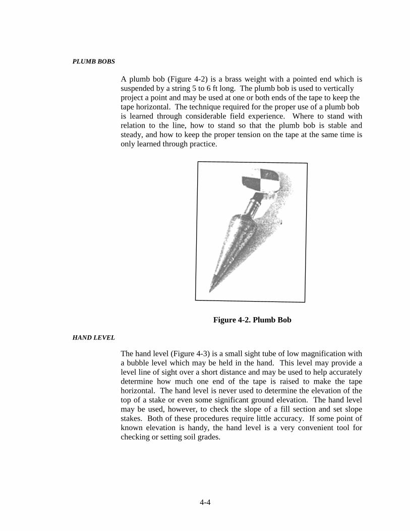
PLUMB BOBS
A plumb bob (Figure 4-2) is a brass weight with a pointed end which is suspended by a string 5 to 6 ft long. The plumb bob is used to vertically project a point and may be used at one or both ends of the tape to keep the tape horizontal. The technique required for the proper use of a plumb bob is learned through considerable field experience. Where to stand with relation to the line, how to stand so that the plumb bob is stable and steady, and how to keep the proper tension on the tape at the same time is only learned through practice.
Figure 4-2. Plumb Bob
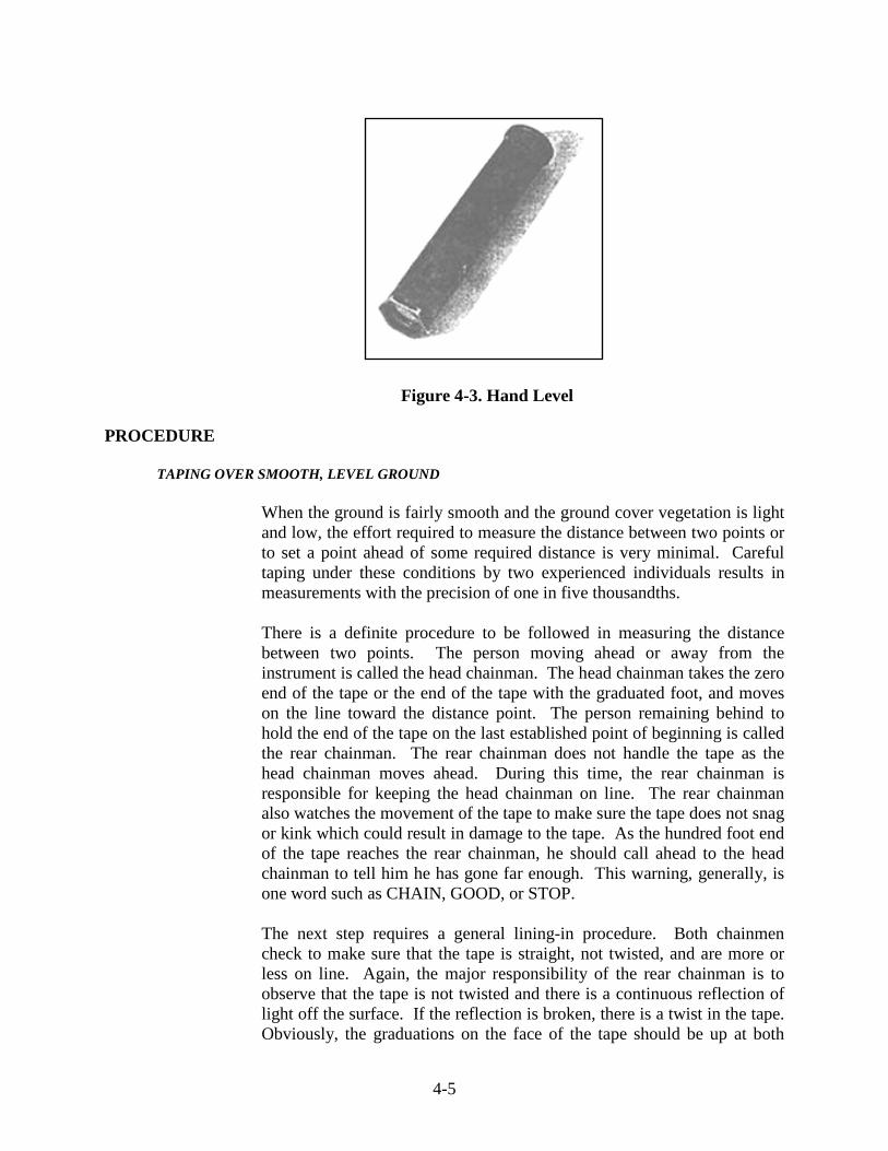
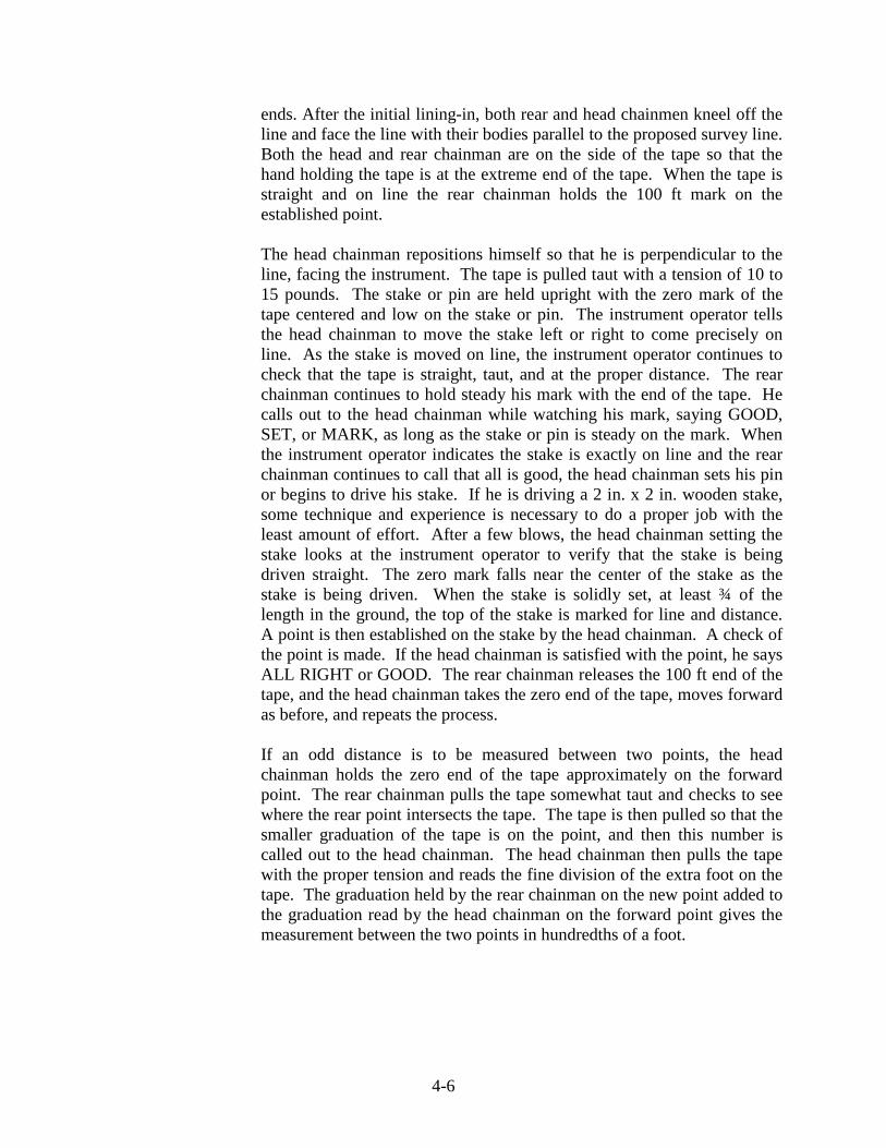
HAND LEVEL
The hand level (Figure 4-3) is a small sight tube of low magnification with a bubble level which may be held in the hand. This level may provide a level line of sight over a short distance and may be used to help accurately determine how much one end of the tape is raised to make the tape horizontal. The hand level is never used to determine the elevation of the top of a stake or even some significant ground elevation. The hand level may be used, however, to check the slope of a fill section and set slope stakes. Both of these procedures require little accuracy. If some point of known elevation is handy, the hand level is a very convenient tool for checking or setting soil grades.
4-5
Figure 4-3. Hand Level
PROCEDURE
TAPING OVER SMOOTH, LEVEL GROUND
When the ground is fairly smooth and the ground cover vegetation is light and low, the effort required to measure the distance between two points or to set a point ahead of some required distance is very minimal. Careful taping under these conditions by two experienced individuals results in measurements with the precision of one in five thousandths. There is a definite procedure to be followed in measuring the distance between two points. The person moving ahead or away from the instrument is called the head chainman. The head chainman takes the zero end of the tape or the end of the tape with the graduated foot, and moves on the line toward the distance point. The person remaining behind to hold the end of the tape on the last established point of beginning is called the rear chainman. The rear chainman does not handle the tape as the head chainman moves ahead. During this time, the rear chainman is responsible for keeping the head chainman on line. The rear chainman also watches the movement of the tape to make sure the tape does not snag or kink which could result in damage to the tape. As the hundred foot end of the tape reaches the rear chainman, he should call ahead to the head chainman to tell him he has gone far enough. This warning, generally, is one word such as CHAIN, GOOD, or STOP. The next step requires a general lining-in procedure. Both chainmen check to make sure that the tape is straight, not twisted, and are more or less on line. Again, the major responsibility of the rear chainman is to observe that the tape is not twisted and there is a continuous reflection of light off the surface. If the reflection is broken, there is a twist in the tape. Obviously, the graduations on the face of the tape should be up at both
4-6
ends. After the initial lining-in, both rear and head chainmen kneel off the line and face the line with their bodies parallel to the proposed survey line. Both the head and rear chainman are on the side of the tape so that the hand holding the tape is at the extreme end of the tape. When the tape is straight and on line the rear chainman holds the 100 ft mark on the established point.
The head chainman repositions himself so that he is perpendicular to the line, facing the instrument. The tape is pulled taut with a tension of 10 to 15 pounds. The stake or pin are held upright with the zero mark of the tape centered and low on the stake or pin. The instrument operator tells the head chainman to move the stake left or right to come precisely on line. As the stake is moved on line, the instrument operator continues to check that the tape is straight, taut, and at the proper distance. The rear chainman continues to hold steady his mark with the end of the tape. He calls out to the head chainman while watching his mark, saying GOOD, SET, or MARK, as long as the stake or pin is steady on the mark. When the instrument operator indicates the stake is exactly on line and the rear chainman continues to call that all is good, the head chainman sets his pin or begins to drive his stake. If he is driving a 2 in. x 2 in. wooden stake, some technique and experience is necessary to do a proper job with the least amount of effort. After a few blows, the head chainman setting the stake looks at the instrument operator to verify that the stake is being driven straight. The zero mark falls near the center of the stake as the stake is being driven. When the stake is solidly set, at least ¾ of the length in the ground, the top of the stake is marked for line and distance. A point is then established on the stake by the head chainman. A check of the point is made. If the head chainman is satisfied with the point, he says ALL RIGHT or GOOD. The rear chainman releases the 100 ft end of the tape, and the head chainman takes the zero end of the tape, moves forward as before, and repeats the process. If an odd distance is to be measured between two points, the head chainman holds the zero end of the tape approximately on the forward point. The rear chainman pulls the tape somewhat taut and checks to see where the rear point intersects the tape. The tape is then pulled so that the smaller graduation of the tape is on the point, and then this number is called out to the head chainman. The head chainman then pulls the tape with the proper tension and reads the fine division of the extra foot on the tape. The graduation held by the rear chainman on the new point added to the graduation read by the head chainman on the forward point gives the measurement between the two points in hundredths of a foot.

4-7
Example:
1) The distance between two stakes is less than 100 ft. 2) The tape is pulled so that the head chainman is holding zero
very close to the forward point, and the rear chainman pulls the tape and finds that the point is between the 63 and 64 graduations on the tape.
3) The rear chainman then pulls the tape and holds the 63
mark on the rear point.
4) The rear chainman then calls to the head chainman saying HOLDING 63.
5) Both chainmen check to make sure the tape is straight, not
twisted, and pulled taut.
6) The head chainman reads 0.58 on the extra foot.
7) The distance between the two points is 63.58 ft. TAPING OVER HILLY, SLOPING GROUND
If the ground is not too rough and hilly and in general considered as gently rolling, the taping procedure required would be slightly more difficult than that required for taping on flat ground. If the plumb bob is used to keep the tape horizontal, the procedure is more difficult. If the terrain is very rough and the slopes are steep with considerable undergrowth or vegetation, the chainmen is required to break tape in addition to plumbing the tape. A one hundred foot distance may require the setting of many intermediate points before the full distance is successfully measured. In any case, the head chainman and rear chainman responsibilities and the orientation of the tape remain the same as was used for taping over level ground. Considerable skill and experience is required to achieve the same level of precision which may be achieved and expected when taping over level ground. The tape is generally unsupported over much of the length when measuring between any two points. The tendency for the tape to sag is very great. There is also a tendency for the head chainman to hold his end too low when going down hill. Patience and technique are very important for this type of taping. If the head chainman is moving down hill toward the forward point and the slope is 5 or 6 ft in a hundred, the full 100 ft may be taped in one measurement. The rear chainman holds the 100 ft mark on the rear established point. The head chainman loops the string of

4-8
the plumb bob over the zero mark, letting the plumb bob fall so that the tape is approximately level between the two end points when the bob is a few inches off the ground (Figure 4-4). The head chainman holds the end of the tape at approximately chest or chin level. He should be in a comfortable position, his body perpendicular or parallel to the proposed line, whichever is more comfortable, and his feet spread so that he has a stable base. An up and down motion of the hands prevents the plumb bob from swinging.
Figure 4-4. Taping Over Hilly Grounds
The rear chainman advises the head chainman of the correct alignment of the tape. The head chainman looks down to see the area where the plumb bob strikes the ground when the tape is on line. He clears this area of loose material and undergrowth before he is ready to set his plumb bob as directed by the instrument operator. The plumb bob is required to be hanging freely an inch or so from the ground with no swing. At this point, the instrument operator gives voice signals so that the head chainman may watch the plumb bob to make sure the plumb bob remains steady as he moves from left to right to bring the plumb bob on line. When the instrument operator determines that the head chainman is on line, he says GOOD and the head chainman sticks the plumb bob into the ground by dropping his hands straight down about 3 to 4 in. The head chainman sets his tape aside, carefully removes the bob, and places the point of stake in the hole made by the plumb bob. He then carefully drives the stake
4-9
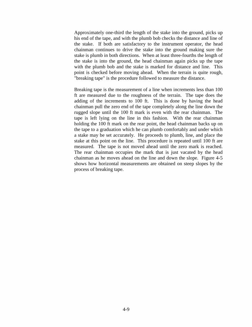
Approximately one-third the length of the stake into the ground, picks up his end of the tape, and with the plumb bob checks the distance and line of the stake. If both are satisfactory to the instrument operator, the head chainman continues to drive the stake into the ground making sure the stake is plumb in both directions. When at least three-fourths the length of the stake is into the ground, the head chainman again picks up the tape with the plumb bob and the stake is marked for distance and line. This point is checked before moving ahead. When the terrain is quite rough, "breaking tape" is the procedure followed to measure the distance.
Breaking tape is the measurement of a line when increments less than 100 ft are measured due to the roughness of the terrain. The tape does the adding of the increments to 100 ft. This is done by having the head chainman pull the zero end of the tape completely along the line down the rugged slope until the 100 ft mark is even with the rear chainman. The tape is left lying on the line in this fashion. With the rear chainman holding the 100 ft mark on the rear point, the head chainman backs up on the tape to a graduation which he can plumb comfortably and under which a stake may be set accurately. He proceeds to plumb, line, and place the stake at this point on the line. This procedure is repeated until 100 ft are measured. The tape is not moved ahead until the zero mark is reached. The rear chainman occupies the mark that is just vacated by the head chainman as he moves ahead on the line and down the slope. Figure 4-5 shows how horizontal measurements are obtained on steep slopes by the process of breaking tape.
4-10
Figure 4-5. Breaking Tape
4-11
TAPING ERROR
Error is defined as the difference between the true value and the measured value of a quantity. Errors result from instrument imperfections, personal limitations, and natural conditions affecting the measurement. An error is either systematic or random. A mistake is not considered an error, but is a blunder on the part of the observer such as the failure to record each 100 ft in taping, misreading a tape, forgetting to level the instrument, etc. Errors in taping may also be caused by one or more of the following reasons:
1) The tape is not the standard length. This results in systematic
error which may be eliminated by standardizing the tape or comparing the true length of the tape with some permanent standard of length. The tape may be sent to the Bureau of Standards in Washington D.C. for standardization or may be standardized in a local laboratory equipped for this type of work. Generally, errors due to this reason may be offset by varying the amount of tension applied to the tape.
2) Poor alignment of the tape. Both chainmen are required to be
constantly aware of the condition of the tape as they move along the line. The instrument operator also helps ensure that the tape is on line over the entire length from point to point. Poor alignment results from sloppy or lazy habits developed by the chainmen. A variable systematic error is produced which may be reduced almost completely if care is exercised in aligning the tape. This is probably the least important of the chaining errors because in 100 ft the error amounts only to 0.005 ft if one end is off line one foot. This type of error tends to make the measured length greater than the true length; therefore, the error is positive.
3) Tape not horizontal. This error produces an effect similar to
that due to poor alignment. Once again, this error results from a sloppy procedure and with a little care may be virtually eliminated. Even an experienced chainman probably underestimates the rate of slope. This may be a large source of error, and in rough or deceptive terrain, hand level may eliminate the error.
4) Tape twisted or not straight. When taping through fairly
dense undergrowth, when the wind is blowing, over a stubble field, or across a harvested cornfield, keeping all parts of the tape in perfect alignment with both ends is difficult. The error in this case is systematic and variable and has the same effect as that which arises from measuring with a tape that is too short.
4-12
5) Human error of observations. There are accidental errors
caused by misreading the tape, improper setting of pins and stakes, and errors due to plumbing improperly due to inexperience or sloppy procedure. All accidental errors may be kept to a minimum by exercising care and following proper procedures.
6) Variations in temperature. Materials expand as the
temperature rises and contract when the temperature falls. In Indiana the ambient air temperature may vary from 10 or 15° below zero to 100 to 105° F. Daily temperatures may vary from 40 to 50°F early in the morning to 80 to 90°F by mid-afternoon. These temperature extremes cause the tape to expand and contract. A change in temperature of 15° F will result in a change in length of about 0.01 ft for a 100 ft tape. The formula for the correction for temperature is as follows:
C = 0.0000065 L (T1 – T2)
where: 0.0000065 = coefficient of thermal expansion of
steel per 1°F L = the measured length in feet T1 = the temperature of measurement in °F T2 = standard temperature of tape in °F
(normally 68° F)
7) Variations in tension. A steel tape is elastic and stretches when tension is applied. The amount of pull is most important and is required to be known to make the tape the right length. Again, this type of error is systematic and depends on the methods employed and who is doing the taping. Generally, a pull of 10 pounds is sufficient when the tape is fully supported. A pull of 20 pounds or more is necessary when the tape is unsupported throughout its length. This information is obtained when the tape is standardized.
4-13
8) Tape Sag. Error due to sag in the tape is significant if the tape is relatively heavy and unsupported over the length of the tape. This may be a very important consideration when both rear and head chainmen are plumbing over rough ground. The tapes typically used for highway surveying are heavy, and both the head and rear chainmen are required to be constantly aware of the amount of sag in the tape when plumbing. Controlling a plumb bob, when applying a tension of 30 pounds to a 100 ft tape which is fully unsupported, is very difficult. This procedure takes considerable effort and experience to do a good job.

5 Cross Sections Side Slopes Field Notes Original Cross Sections Profiles Vertical Sections Zero Section Split Section Match Lines Interpolation Earthwork Quantities
5-1
CHAPTER FIVE: CROSS SECTIONS
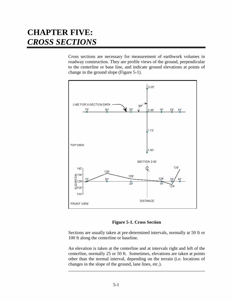
Cross sections are necessary for measurement of earthwork volumes in roadway construction. They are profile views of the ground, perpendicular to the centerline or base line, and indicate ground elevations at points of change in the ground slope (Figure 5-1).
Figure 5-1. Cross Section
Sections are usually taken at pre-determined intervals, normally at 50 ft or 100 ft along the centerline or baseline. An elevation is taken at the centerline and at intervals right and left of the centerline, normally 25 or 50 ft. Sometimes, elevations are taken at points other than the normal interval, depending on the terrain (i.e. locations of changes in the slope of the ground, lane lines, etc.). ____________________________________________________________

5-2
SIDE SLOPES
Side slope (Figure 5-2) is defined as the slope of the cut or fill expressed as the ratio of horizontal distance to vertical distance.
Figure 5-2. Side Slope Example:
A 2:1 side slope indicates that for every horizontal distance of 2 ft, the corresponding vertical distance is 1 ft as indicated in the following diagram:
5-3
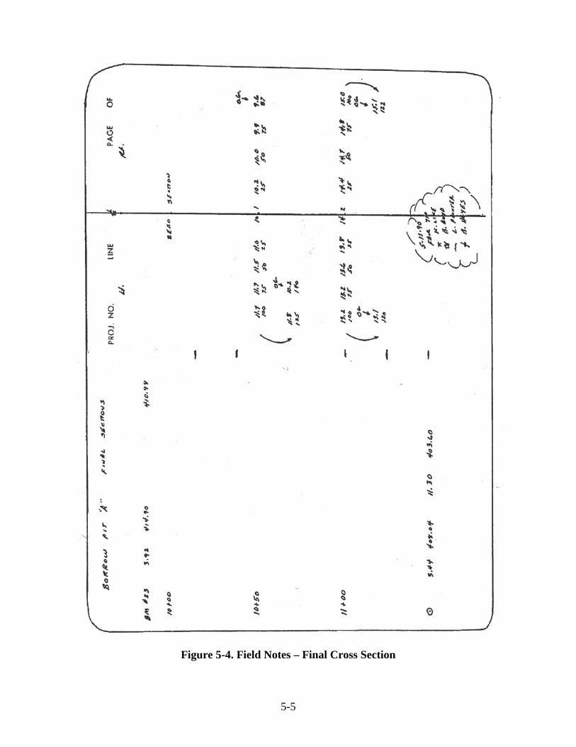
FIELD NOTES
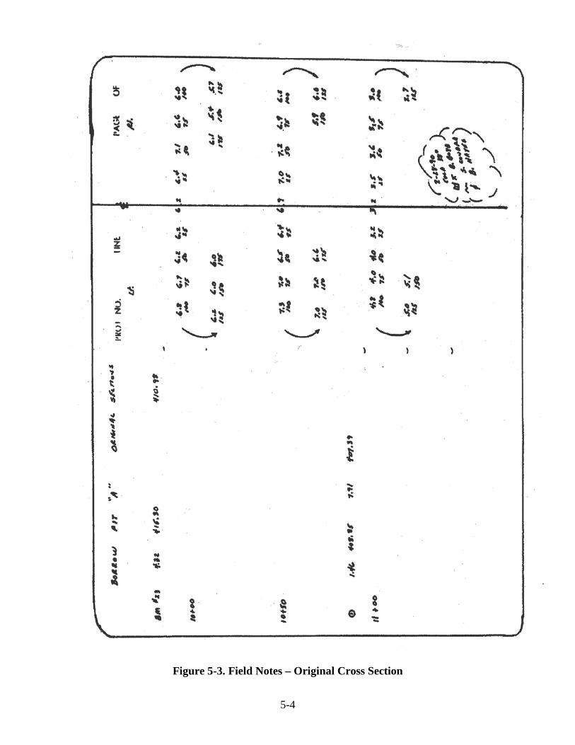
Field notes (Figures 5-3 and 5-4) are recorded in the field books. Reference notes, such as EP (edge of pavement), CL (centerline), TS (toe of slope), TB (top of bank), OG (original ground), and where each shot (elevation) is taken are recorded. The accuracy of any readings taken is required to be 0.1 ft on the ground and 0.01 ft on the pavement.
ORIGINAL CROSS SECTIONS
Original cross sections indicate the profile of the original ground before the ground is disturbed. These measurements may be used for primary design, estimating volumes, etc. Borrow pit original cross sections (Figures 5-3 and 5-4) are taken after stripping has occurred. Before beginning a contract, the original cross sections are checked every 500 ft and compared to the cross sections shown on the plans. If these check sections vary consistently by more than 0.2 ft, the original sections may have to be retaken.
5-4
Figure 5-3. Field Notes – Original Cross Section
5-5
Figure 5-4. Field Notes – Final Cross Section
5-6
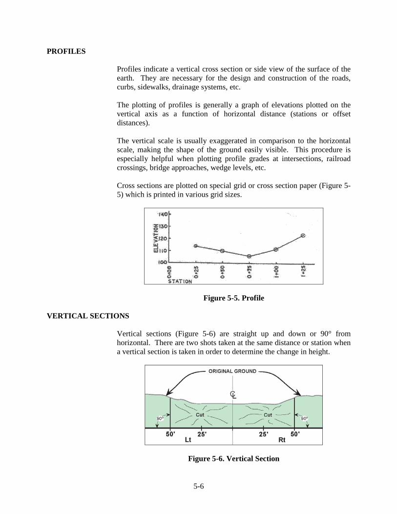
PROFILES
Profiles indicate a vertical cross section or side view of the surface of the earth. They are necessary for the design and construction of the roads, curbs, sidewalks, drainage systems, etc. The plotting of profiles is generally a graph of elevations plotted on the vertical axis as a function of horizontal distance (stations or offset distances). The vertical scale is usually exaggerated in comparison to the horizontal scale, making the shape of the ground easily visible. This procedure is especially helpful when plotting profile grades at intersections, railroad crossings, bridge approaches, wedge levels, etc. Cross sections are plotted on special grid or cross section paper (Figure 5-5) which is printed in various grid sizes.
Figure 5-5. Profile
VERTICAL SECTIONS
Vertical sections (Figure 5-6) are straight up and down or 90° from horizontal. There are two shots taken at the same distance or station when a vertical section is taken in order to determine the change in height.
Figure 5-6. Vertical Section
5-7
ZERO SECTION
A zero section is a section at which no earthwork was done. These usually occur at the beginning and ending of contracts.
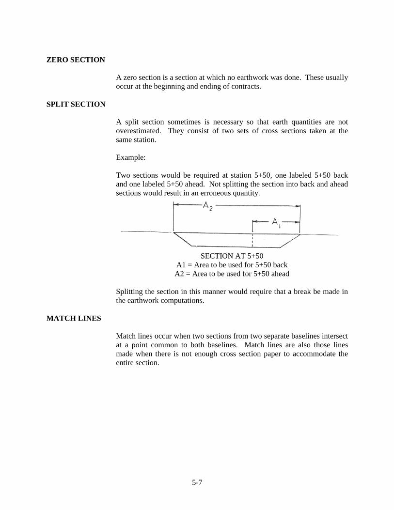
SPLIT SECTION
A split section sometimes is necessary so that earth quantities are not overestimated. They consist of two sets of cross sections taken at the same station. Example: Two sections would be required at station 5+50, one labeled 5+50 back and one labeled 5+50 ahead. Not splitting the section into back and ahead sections would result in an erroneous quantity.
SECTION AT 5+50
A1 = Area to be used for 5+50 back A2 = Area to be used for 5+50 ahead
Splitting the section in this manner would require that a break be made in the earthwork computations.
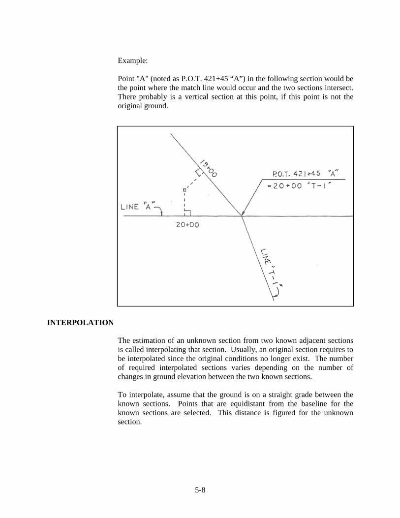
MATCH LINES
Match lines occur when two sections from two separate baselines intersect at a point common to both baselines. Match lines are also those lines made when there is not enough cross section paper to accommodate the entire section.
5-8
Example: Point "A" (noted as P.O.T. 421+45 “A”) in the following section would be the point where the match line would occur and the two sections intersect. There probably is a vertical section at this point, if this point is not the original ground.
INTERPOLATION
The estimation of an unknown section from two known adjacent sections is called interpolating that section. Usually, an original section requires to be interpolated since the original conditions no longer exist. The number of required interpolated sections varies depending on the number of changes in ground elevation between the two known sections.
To interpolate, assume that the ground is on a straight grade between the known sections. Points that are equidistant from the baseline for the known sections are selected. This distance is figured for the unknown section.

5-9
Example: To figure the elevation of a point 50 ft left of a baseline at station 50+38, the following illustration explains the procedure:
X = the difference in elevation from station 50+00 to station 50+38. 38 is to 100 as X is to 60 therefore, 38/100 = X/60 X = (38/100) x 60 = 22.8 feet Note that the ground elevation from station 50+00 to 51+00 is rising. This means that the elevation at station 50+38 is greater than the elevation at station 50+00. Therefore, 22.8 ft is added to 425.00 to obtain the elevation at station 50+38.
Elevation at Station 50+38 = 425.00 + 22.80 = 447.80 ft
5-10
EARTHWORK QUANTITIES
Earthwork quantities are usually measured in cubic yards and may be a cut or fill. The volumes are computed as the product of an area and a distance. The methods for determining areas include:
1) Picking or stripping. 2) Plane geometry. 3) Planimeter. 4) Coordinates.
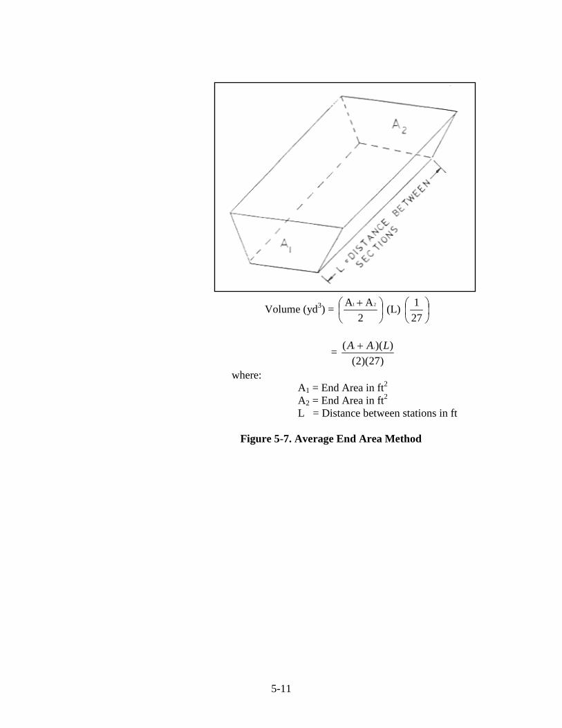
Plane geometry, the most commonly used method by INDOT, requires dividing the section into regular shapes such as triangles and trapezoids. Dimensions may be determined by scaling or from field data. Areas are computed from basic geometric formulas. Once the areas of the sections are determined, the volume between two adjacent sections may be computed by using the Average End Area Method (Figure 5-7).
5-11
Volume (yd3) =
+
2AA 21 (L)
271
= )27)(2(
))(( 21 LAA +
where: A1 = End Area in ft2 A2 = End Area in ft2 L = Distance between stations in ft
Figure 5-7. Average End Area Method

5-12
Example: Given the end sections as follows, determine the quantity of earthwork.
Area 1 Area1 = ½ (28.0 ft) (50.0 ft) = 700.0 ft2
Area 2
Area2 =
+
245.0ft50.0ft (69.9)
= 3320.0 ft2
Area 3
Area3 = ½ (41.0 ft) (45.0 ft) = 922.5 ft2
Total Area A1 = 700.0 ft2 + 3320.3 ft2 + 922.5 ft2
= 4942.8 ft2
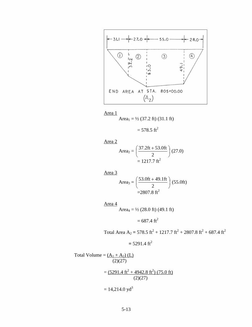
5-13
Area 1 Area1 = ½ (37.2 ft) (31.1 ft) = 578.5 ft2 Area 2
Area2 =
+
253.0ft37.2ft (27.0)
= 1217.7 ft2
Area 3
Area3 =
+
249.1ft53.0ft (55.0ft)
=2807.8 ft2
Area 4
Area4 = ½ (28.0 ft) (49.1 ft) = 687.4 ft2
Total Area A2 = 578.5 ft2 + 1217.7 ft2 + 2807.8 ft2 + 687.4 ft2
= 5291.4 ft2
Total Volume = (A1 + A2) (L)
(2)(27) = (5291.4 ft2 + 4942.8 ft2) (75.0 ft) (2)(27) = 14,214.0 yd3
6 Slope Stakes Definitions Control Point Grade Rod Ground Rod Reading Slope Stakes Setting Slope Stakes Field Procedure
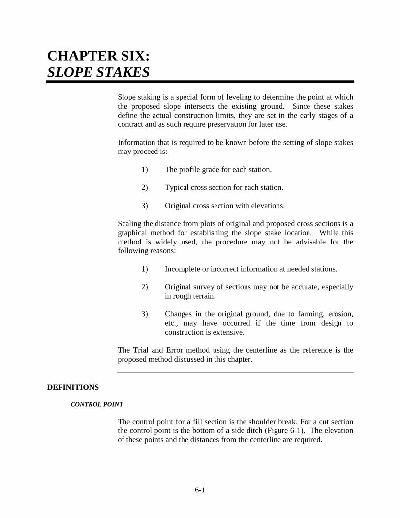
6-1
CHAPTER SIX: SLOPE STAKES
Slope staking is a special form of leveling to determine the point at which the proposed slope intersects the existing ground. Since these stakes define the actual construction limits, they are set in the early stages of a contract and as such require preservation for later use. Information that is required to be known before the setting of slope stakes may proceed is:
1) The profile grade for each station. 2) Typical cross section for each station. 3) Original cross section with elevations.
Scaling the distance from plots of original and proposed cross sections is a graphical method for establishing the slope stake location. While this method is widely used, the procedure may not be advisable for the following reasons:
1) Incomplete or incorrect information at needed stations. 2) Original survey of sections may not be accurate, especially
in rough terrain. 3) Changes in the original ground, due to farming, erosion,
etc., may have occurred if the time from design to construction is extensive.
The Trial and Error method using the centerline as the reference is the proposed method discussed in this chapter.
DEFINITIONS
CONTROL POINT
The control point for a fill section is the shoulder break. For a cut section the control point is the bottom of a side ditch (Figure 6-1). The elevation of these points and the distances from the centerline are required.
6-2
Figure 6-1. Control Points

6-3
GRADE ROD
A grade rod is defined as the height of instrument (HI) minus the control point elevation.
GROUND ROD
The ground rod is the actual rod reading during a trial. The grade rod reading minus the ground rod reading designates whether the section is a cut or fill section.
READING SLOPE STAKES
Slope stakes are necessary to determine if the roadway is being built to the required lines and grades. The slope stake is the tool that is used to ensure that slopes are graded correctly and fill or cuts are made to the required elevations. The following example explains how to read a typical slope stake.
Example:
Starting at the slope stake, the following steps are taken:
1) Cut the back slope 4 ft deep at a 2:1 slope. 2) Grade a 4 ft ditch bottom. 3) Go up the foreslope 4 ft at a 4:1 slope. 4) Go 2 ft at a 4 % slope for the shoulder. 5) Go 12 ft at a 2 % slope to the centerline.

6-4
SETTING SLOPE STAKES
Setting slope stakes may be done in the office or with actual measurements in the field. Both methods are trial and error procedures that determine the control point elevations and distances from the centerline for each station.
FIELD PROCEDURE
The field procedure for determining the location of the slope stakes is as follows:
1) Set up the level and determine the HI. 2) Determine Grade Rods: Grade Rod = HI – control point
elevation. 3) Take a trial ground rod reading at a measured distance from
the centerline. 4) Using the grade rod, ground rod, rate of slope, and standard
distance, determine the computed distance to the slope stake from the centerline.
5) Compare the measured distance and the computed distance.
If they differ by more than ± 0.5 ft, a new trial is required.
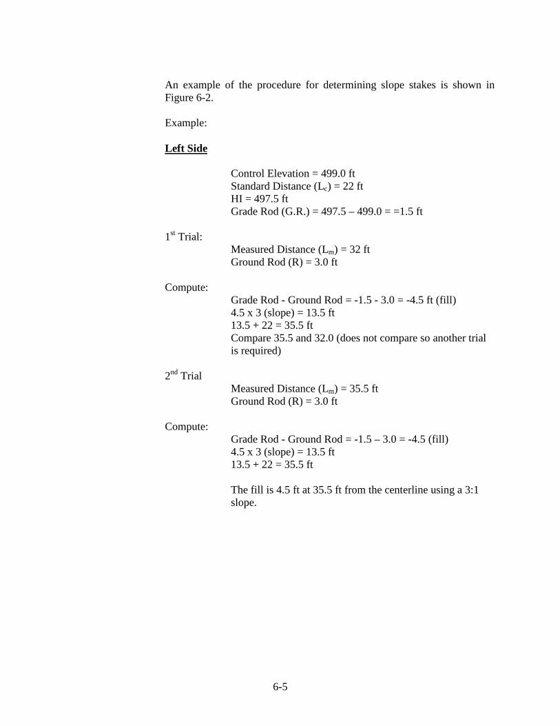
6-5
An example of the procedure for determining slope stakes is shown in Figure 6-2. Example: Left Side Control Elevation = 499.0 ft Standard Distance (Lc) = 22 ft HI = 497.5 ft Grade Rod (G.R.) = 497.5 – 499.0 = =1.5 ft 1st Trial: Measured Distance (Lm) = 32 ft Ground Rod (R) = 3.0 ft Compute:
Grade Rod - Ground Rod = -1.5 - 3.0 = -4.5 ft (fill) 4.5 x 3 (slope) = 13.5 ft 13.5 + 22 = 35.5 ft Compare 35.5 and 32.0 (does not compare so another trial is required)
2nd Trial Measured Distance (Lm) = 35.5 ft Ground Rod (R) = 3.0 ft Compute: Grade Rod - Ground Rod = -1.5 – 3.0 = -4.5 (fill) 4.5 x 3 (slope) = 13.5 ft 13.5 + 22 = 35.5 ft
The fill is 4.5 ft at 35.5 ft from the centerline using a 3:1 slope.

6-6
Right Side Control Elevation = 497.0 ft Standard Distance (Lc) = 29 ft HI = 503.5 ft Grade Rod (G.R.) = 503.5 – 497.0 = +6.5 ft 1st Trial: Measured Distance (Lm) = 38 ft Ground Rod (R) = 1.5 ft Compute: Grade Rod – Ground Rod = 6.5 – 1.5 = +5 ft (cut) 5.0 x 2 (slope) = 10 ft 29 + 10 = 39.0 ft Compare 39 and 38 (try 39 ft) 2nd Trial: Measured Distance (Lm) = 39 ft Ground Rod (R) = 1.5 ft Compute: Grade Rod - Ground Rod = 6.5 – 1.5 = +5.0 (cut) 5.0 x 2 (slope) = 10 ft 10 + 29 = 39 ft
The cut is 5.0 ft at 39 ft from the centerline using a 2:1 slope.
Figure 6-3 gives an example of the notes required for determining the slope stakes. For this example, the readings were not within the allowable difference of ± 0.5 ft and therefore another trial is required.

6-7
Figure 6-2. Slope Stake Problem

6-8
Figure 6-3. Slope Stake Notes


7 Radius Layout Layouts for Square Drives/Approaches Layouts for Skew Drives/Approaches
7-1
CHAPTER SEVEN: RADIUS LAYOUT
The layout of a radius point may be done by a single person with a steel, fiberglass, or cloth tape. Since a cloth tape is subject to stretching or shrinking, depending upon the age and/or weather conditions, a steel or fiberglass tape is preferred.
LAYOUTS FOR SQUARE DRIVES/APPROACHES
The procedure used for determining a layout for a square drive or approach (Figure 7-1) is as follows:
1) Determine the intersecting point of the driveway or approach (station number) and the width of the drive or approach.
2) Measure one half of the drive width along the edge of
pavement from the intersecting point and mark this as point A.
3) Measure the radius distance from point A along the edge of
pavement and mark this as point B. 4) Measure the radius distance from point B perpendicularly
and mark this as point C, which is the radius point.
A chaining pin is used first to mark point C. If the radius fits when the radius distance is swung from this point, a hub with a nail may be set to mark the point. If the radius does not fit, point C may be adjusted by moving the chaining pin and rechecking before driving the hub. After the hub is set, the radius may be set by hooking the end of the tape over the nail (Figure 7-1).
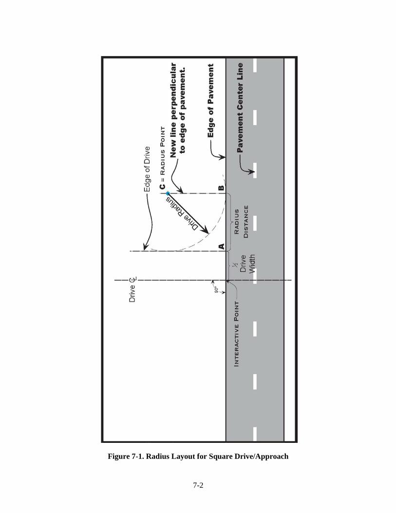
7-2
Figure 7-1. Radius Layout for Square Drive/Approach

7-3
Figure 7-2. Determining Radius Point
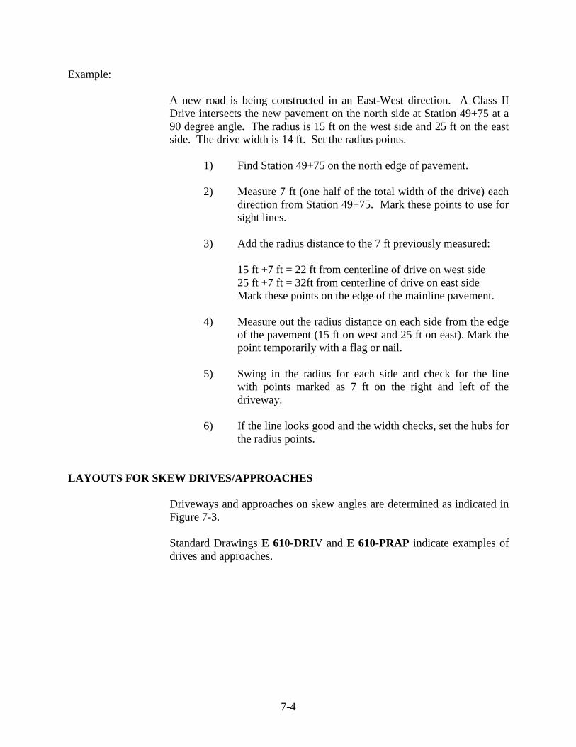
7-4
Example:
A new road is being constructed in an East-West direction. A Class II Drive intersects the new pavement on the north side at Station 49+75 at a 90 degree angle. The radius is 15 ft on the west side and 25 ft on the east side. The drive width is 14 ft. Set the radius points.
1) Find Station 49+75 on the north edge of pavement. 2) Measure 7 ft (one half of the total width of the drive) each
direction from Station 49+75. Mark these points to use for sight lines.
3) Add the radius distance to the 7 ft previously measured:
15 ft +7 ft = 22 ft from centerline of drive on west side 25 ft +7 ft = 32ft from centerline of drive on east side Mark these points on the edge of the mainline pavement. 4) Measure out the radius distance on each side from the edge
of the pavement (15 ft on west and 25 ft on east). Mark the point temporarily with a flag or nail.
5) Swing in the radius for each side and check for the line
with points marked as 7 ft on the right and left of the driveway.
6) If the line looks good and the width checks, set the hubs for
the radius points. LAYOUTS FOR SKEW DRIVES/APPROACHES
Driveways and approaches on skew angles are determined as indicated in Figure 7-3. Standard Drawings E 610-DRIV and E 610-PRAP indicate examples of drives and approaches.
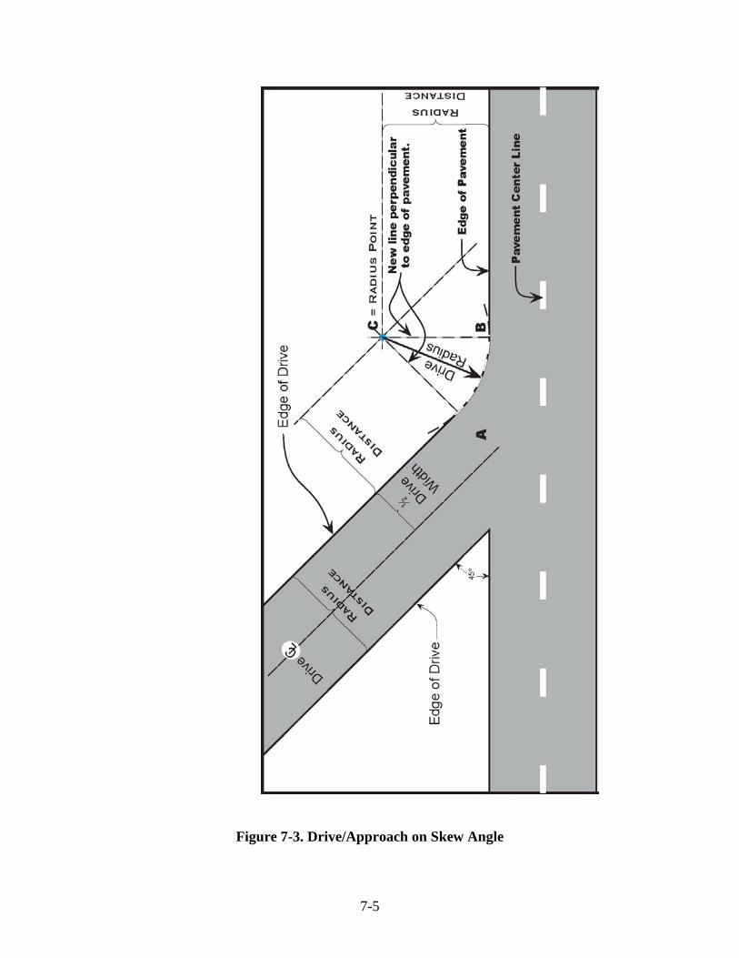
7-5
Figure 7-3. Drive/Approach on Skew Angle
8 Turn Lanes Driveways Mailbox Approaches

8-1
CHAPTER EIGHT: TURN LANES
Turn lanes are used in conjunction with Public Road Approaches Type C and Type D. These approaches are indicated on the Standard Drawings E 610-PRAP-01 through E 610-PRAP-14. The lengths of the tapers and the turn lanes are dependent upon the design speed of the mainline pavement, the angle of the intersection, and the traffic count of the intersecting approach. The tables on the Standard Drawings are used to determine the required distances when the design speed, vertical roadway grade, and angle of intersection are known. These distances are then measured from the station number given for the approach intersection. After the required offsets are measured and marked, the radius points may then be set
DRIVEWAYS
Driveways are indicated on Standard Drawings E 610-DRIV-01 through E 610-DRIV-21. There are several types of drives as follows:
CLASS I: Private Drive, 6 inch concrete, 10 to 20 ft wide
CLASS II: Private Drive, 4 inch HMA, 12 to 24 ft wide
CLASS III: Commercial Drive, 6 inch concrete, 20 to 40 ft wide
CLASS IV: Commercial Drive, 4 inch HMA, 20 to 40 ft wide
CLASS V: Field Entrance (dirt), 24 ft minimum width (32 ft is
desirable) CLASS VI: Heavy Industrial and truck stops, concrete or HMA, 6.5 in.
minimum thickness, 32 to 50 ft wide
CLASS VII: Heavy Industrial and truck stops, concrete, 6 in. minimum thickness, 32 to 50 ft wide
Using the class, station number and width of the drives as given in the approach table in the plans, the radius points may be set and the drives marked out as previously discussed.
8-2
MAILBOX APPROACHES
Approaches for driveways and mailboxes are indicated on Standard Drawings E 610-MBAP-01 and E 610-MBAP-02. There are three types of approaches:
1) Mailbox only. 2) Mailbox in advance of the drive. 3) Mailbox beyond the drive.
The width of the approach varies according to the traffic volume of the road. The low traffic volume width is used only when the design speed is less than 40 mph and the ADT is less than 100. Normally, approaches are a minimum of 8 ft wide for an ADT of less than 1500 and 10 ft wide for an ADT over 1500. Most HMA resurface contracts have approach widths of 8 ft maximum. On some older roads, mailbox approaches may be only 2 ft wide. The required dimensions are given on the Standard Drawings. On new construction contracts, the approaches may be marked out using the stations given in the approach table on the plans and the dimensions from the Standard Drawings. Adjustments may be necessary so that the approaches match the existing driveways. On resurface contracts, the stations for driveways and mailboxes are not given and they are required to be marked out to match what exists in the field.


9 Pipe Structures Pipe Types Pipe End Treatments Pipe End Section Grated Box End Section Structure Order Pipe Order Cross-Section View Computing Structure Length Using Elbows Structure Field Layout Staking Structures Normal Layout Laser Layout Checking Grade Batterboard and Stringline Laser Grade Control Basis of Use for Pipe Materials Metal Pipe Concrete Pipe Plastic Pipe Metal Pipe End Safety Metal End Section Other Items Recording Tags for Basis of Use Multi-Plate Pipe Miscellaneous Concrete Recording Tags for Future Use
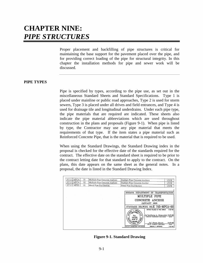
9-1
CHAPTER NINE: PIPE STRUCTURES
Proper placement and backfilling of pipe structures is critical for maintaining the base support for the pavement placed over the pipe, and for providing correct loading of the pipe for structural integrity. In this chapter the installation methods for pipe and sewer work will be discussed.
PIPE TYPES
Pipe is specified by types, according to the pipe use, as set out in the miscellaneous Standard Sheets and Standard Specifications. Type 1 is placed under mainline or public road approaches, Type 2 is used for storm sewers, Type 3 is placed under all drives and field entrances, and Type 4 is used for drainage tile and longitudinal underdrains. Under each pipe type, the pipe materials that are required are indicated. These sheets also indicate the pipe material abbreviations which are used throughout construction in the plans and proposals (Figure 9-1). When pipe is listed by type, the Contractor may use any pipe material that meets the requirements of that type. If the item states a pipe material such as Reinforced Concrete Pipe, that is the material that is required to be used. When using the Standard Drawings, the Standard Drawing index in the proposal is checked for the effective date of the standards required for the contract. The effective date on the standard sheet is required to be prior to the contract letting date for that standard to apply to the contract. On the plans, this date appears on the same sheet as the general notes. In a proposal, the date is listed in the Standard Drawing Index.
Figure 9-1. Standard Drawing

9-2
Besides listing pipe materials, the Standard Drawings list notes for cover limits and other installation information. Standard Drawing E 715-PIPE-01 is checked for the pipe type listing table. Construction details shall be in accordance with Standard Specifications Section 715.
PIPE END TREATMENTS
There are several different types of pipe end treatments being used. The Technician is required to know which type is required for each structure because some end treatments affect the length of pipe necessary for construction. The standard drawings indicate details for each type of end treatment. The end treatments used are as follows:
1) Metal pipe end sections.
2) Safety metal end sections.
3) Concrete pipe anchors.
4) Grated box end sections.
5) Inlets or catch basins.
6) Manholes.
Of the units indicated above only concrete pipe anchors do not affect the overall length of a pipe structure significantly. The following drawings indicate how different pipe end treatments affect the pipe length.
PIPE END SECTION
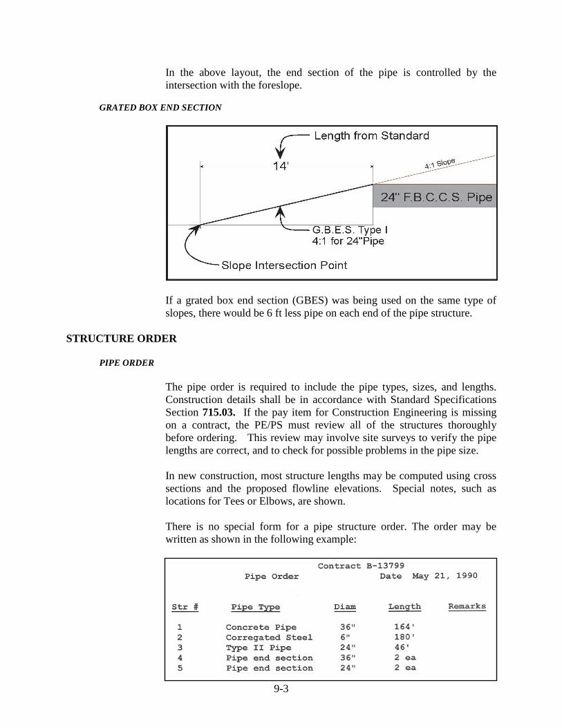
9-3
In the above layout, the end section of the pipe is controlled by the intersection with the foreslope.
GRATED BOX END SECTION
If a grated box end section (GBES) was being used on the same type of slopes, there would be 6 ft less pipe on each end of the pipe structure.
STRUCTURE ORDER
PIPE ORDER
The pipe order is required to include the pipe types, sizes, and lengths. Construction details shall be in accordance with Standard Specifications Section 715.03. If the pay item for Construction Engineering is missing on a contract, the PE/PS must review all of the structures thoroughly before ordering. This review may involve site surveys to verify the pipe lengths are correct, and to check for possible problems in the pipe size. In new construction, most structure lengths may be computed using cross sections and the proposed flowline elevations. Special notes, such as locations for Tees or Elbows, are shown. There is no special form for a pipe structure order. The order may be written as shown in the following example:
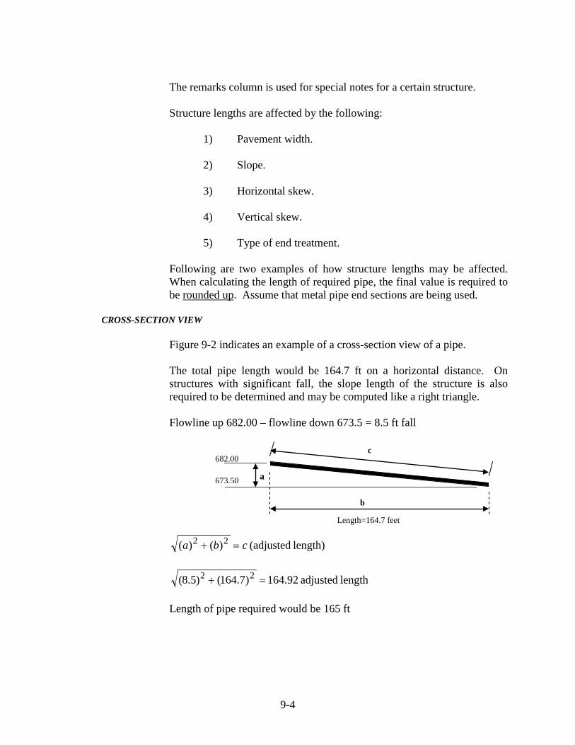
9-4
The remarks column is used for special notes for a certain structure.
Structure lengths are affected by the following:
1) Pavement width.
2) Slope.
3) Horizontal skew.
4) Vertical skew.
5) Type of end treatment.
Following are two examples of how structure lengths may be affected. When calculating the length of required pipe, the final value is required to be rounded up. Assume that metal pipe end sections are being used.
CROSS-SECTION VIEW
Figure 9-2 indicates an example of a cross-section view of a pipe.
The total pipe length would be 164.7 ft on a horizontal distance. On structures with significant fall, the slope length of the structure is also required to be determined and may be computed like a right triangle.
Flowline up 682.00 – flowline down 673.5 = 8.5 ft fall
length) (adjusted )()( 22 cba =+
length adjusted 164.92)7.164()5.8( 22 =+ Length of pipe required would be 165 ft
c
b
Length=164.7 feet
a 673.50
682.00
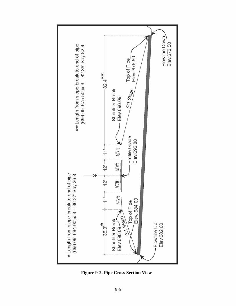
9-5
Figure 9-2. Pipe Cross Section View
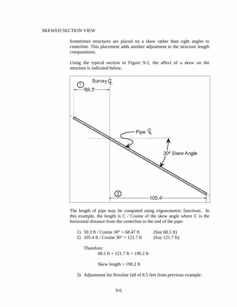
9-6
SKEWED SECTION VIEW Sometimes structures are placed on a skew rather than right angles to centerline. This placement adds another adjustment to the structure length computations. Using the typical section in Figure 9-2, the affect of a skew on the structure is indicated below.
The length of pipe may be computed using trigonometric functions. In this example, the length is C / Cosine of the skew angle where C is the horizontal distance from the centerline to the end of the pipe:
1) 59.3 ft / Cosine 30° = 68.47 ft (Say 68.5 ft) 2) 105.4 ft / Cosine 30° = 121.7 ft (Say 121.7 ft)
Therefore: 68.5 ft + 121.7 ft = 190.2 ft
Skew length = 190.2 ft
3) Adjustment for flowline fall of 8.5 feet from previous example:

9-7
ft) 190.4(Say ft 190.39)2.190()5.8( 22 =+ Order length would be 191 ft (rounded up)
COMPUTING STRUCTURE LENGTH USING ELBOWS
Sometimes structures use elbows or bends to decrease the depth of cut in large fills. The following example (Figure 9-3) displays the proper method for computing pipe lengths when bends or elbows are used.
E-7 Inlet inside measure = 2.5 ft/ 2 = 1.25 ft on CL to end of pipe If elbows = 4 ft measured along CL: Section (1) = 75 ft – Inlet offset (1.25 ft) – Elbow = 75 – 1.25 – (4/2) = 71.75 (Say 72 ft) Section (2) = FL up 696.29 – FL Down 677.96 = 18.33 ft
ft 57.9755)((18.33)Length 22 =+=
57.97 ft – (8/2 ft for 2 elbows) = 53.97 ft (Say 54 ft) Section (3) = 15 ft – 2 ft for elbow + ((680.08 – 676.29) x 3)
= 24.37 (Say 25 ft) Totals Section (1) 72 ft (2) 54 ft (3) 25 ft _______________________________
151 ft plus 2 elbows & 1 pipe end treatment

9-8
Figure 9-3. Structure with Bend or Elbow
9-9
The pipe order indicates the layout on a structure like Figure 9-3 rather than just the total pipe required. Otherwise, the pipe manufacturer would not break down the total length into pieces suitable for the planned assembly.
STRUCTURAL FIELD LAYOUT
STAKING STRUCTURES
Each structure is required to have a layout drawing showing the structure and the stake locations. The Contractor is required to indicate what method of grade control is planned. Laser grade control on long pipe or sewer runs is currently being used by some Contractors.
NORMAL LAYOUT
On normal staking layouts, the stakes are set on an offset line parallel to the pipe and spaced approximately every 25 ft, at an alignment change, or at a grade break. Stakes are set at a specified distance from the centerline of the pipe structure so that the centerline may be re-established as needed. Also, stakes are set where they are least likely to be disturbed. How the Contractor plans to place the structure is discussed before the layout begins. All Contractors work differently and sometimes one side of the structure may be preferred for placing the stakes.
After staking a structure, the layout is discussed with the Contractor and a copy of the layout provided. All stakes are labeled clearly so the layout may be easily followed. Stakes are marked for line only or line and grade offset. The position of the pipe relative to the survey centerline is clearly indicated.
LASER LAYOUT
When the Contractor uses laser grade control, the Technician is required to know the flowline fall expressed in "percent of fall". This value is computed by the formula:
FL Elev. Upstream – FL Elev. Downstream x 100% Horizontal Length of Pipe

9-10
CHECKING GRADE
The different methods of checking the grade from structure stakes include the following:
1) Level rod readings taken from structure stakes to
excavation trench.
2) Batterboard and stringline.
3) Laser grade control.
BATTERBOARD AND STRINGLINE
The batterboard and stringline method uses a post and a crossarm mounted a predetermined height above each grade stake. The crossarm is required to be level and have a stringline on either end. The stringlines are stretched from one batterboard to the next, and the grade is checked by sighting across the stringlines to the level rod.
Example:
To set a batterboard for a constant 8 ft cut Cut from grade stake #1 = 6.18
Measure up = 1.82 (grade stake to top of batter board) Reading to FL 8.00
Cut from grade stake #2 = 5.13
Measure up = 2.87 (grade stake to top of batter board) Reading to FL 8.00

9-11
LASER GRADE CONTROL
When using laser grade control, a known elevation point is first established, relative to the structure flowline. The laser is then set up a specified distance above that point and the percent of fall dialed in. To check the grade anywhere along the flowline, the predetermined distance is measured down from the laser beam.
BASIS OF USE FOR PIPE MATERIALS
Different types of pipe materials have different testing markings.
METAL PIPE
Metal pipe items are marked with metal tags having a 6 digit number stamped onto the tag. This tag verifies that the pipe has been inspected.
CONCRETE PIPE
Concrete pipe items are required to be produced by a Certified Precast Concrete Producer on the Approved list. The pipe is required to have the date of manufacture and the source number on the pipe. Also, pipe manufactured by a Producer who is also certified by the American Concrete Pipe Association is required to have the "QCast "symbol or have the words "ACPA Certified Material" on the pipe. Pipe manufactured by a manufacturer also certified by the National Precast Concrete Association is required to have the words "NPCA Certified Material" on the pipe.
PLASTIC PIPE
Plastic pipe items are accepted by a Certification stating that the pipe meets the required Specification ratings. This certification is usually a Type A or Type C as indicated in the Frequency Manual.

9-12
METAL PIPE END
Metal pipe end sections have tag numbers as described for metal pipe.
SAFETY METAL END SECTION
Safety metal end sections have tag numbers as described for metal pipe.
OTHER ITEMS
Precast inlets, catchbasins, manholes, and GBES are required to be produced by Producers that are on the Approved list for Certified Precast Concrete Producers the same as concrete pipe.
RECORDING TAGS FOR BASIS OF USE
When a shipment of metal pipe arrives on the job-site, all tag numbers on the invoice are recorded as the pipe is checked. The count of these numbers and units is required to agree with what the Supplier is indicating. The PE/PS also receives a report (TD-392) from the pipe plant Technician indicating all the pipes produced and the corresponding tag numbers.
MULTI-PLATE PIPE
On structural plate steel pipe or multi-plate pipe, a yellow card is attached to the invoice indicating the inspection numbers. A pipe report is issued by the pipe Technician, similar to the report for the other pipe items.
MISCELLANEOUS CONCRETE
For any concrete items poured in place, such as pipe anchors, inlets, or pipe collars, the basis of use is the report number from the IT 652.
RECORDING TAGS FOR FUTURE USE
When placing pipe items, the pipe tag numbers are recorded in the Technician’s daily reports and in the structure book. These numbers are used by the PE/PS to obtain lab numbers necessary for the completion of the material record.

10 Pipe Placement Excavation Rock Excavation Unsuitable Material Excess Excavation Payment Removal of Existing Structures Safety Laying Pipe Structure Bearing Laying Concrete or Clay Bell Pipe ABS Pipe Metal Pipe Multi-Plate Pipe Joining Pipe Joining Pipe with Collars Stub-Tee Connections Metal Pipe Concrete Pipe Pipe End Treatments Pipe Anchors Pipe End Sections Grated Box End Sections and Safety Metal End Sections
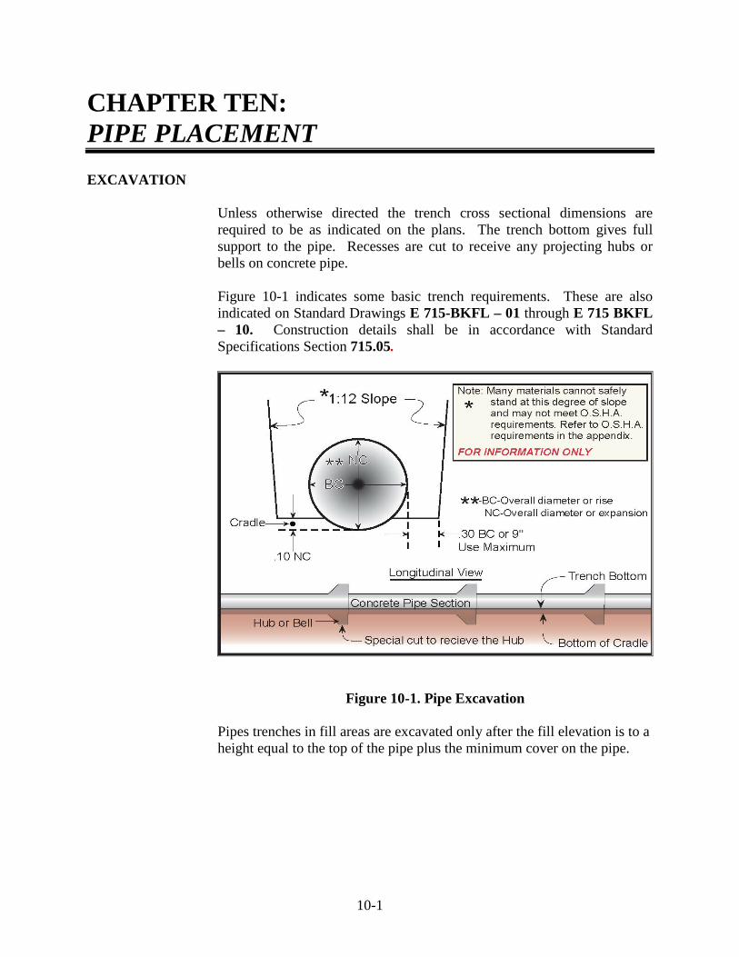
10-1
CHAPTER TEN: PIPE PLACEMENT EXCAVATION
Unless otherwise directed the trench cross sectional dimensions are required to be as indicated on the plans. The trench bottom gives full support to the pipe. Recesses are cut to receive any projecting hubs or bells on concrete pipe. Figure 10-1 indicates some basic trench requirements. These are also indicated on Standard Drawings E 715-BKFL – 01 through E 715 BKFL – 10. Construction details shall be in accordance with Standard Specifications Section 715.05.
Figure 10-1. Pipe Excavation
Pipes trenches in fill areas are excavated only after the fill elevation is to a height equal to the top of the pipe plus the minimum cover on the pipe.

10-2
The recommended cover, where heavy construction equipment crosses the pipe structure, is as follows:
1) Up to and including 18 in. diameter or equal – 1 ft 6 in. cover.
2) Greater than 18 in. diameter up to and including 54 in.
diameter or equal – 3 ft cover.
3) Greater than 54 in. diameter or equal – 4 ft cover.
When the fill height is sufficient to provide the cover listed, the structure may be placed.
ROCK EXCAVATION
When rock is encountered during trench excavation at the flowline elevation, the trench bottom is required to be excavated at least 8 in. below the required elevation, backfilled with B borrow to the proper grade, and compacted to INDOT Standard Specification requirements.
UNSUITABLE MATERIAL
Any time soft or unstable material is found at the required flowline elevation, such material is required to be removed and replaced. B borrow may be used as the replacement material.
EXCESS EXCAVATION PAYMENT
Cut volumes and B borrow for replacing soft areas are required to be recorded. If the quantity of excavation exceeds 10 yd3, the quantity is paid as three times the excavation class required.
REMOVAL OF EXISTING STRUCTURES
Normally, removal of an existing structure is included in the cost of a new structure item unless a special item is included for the removal. This procedure consists of removing the existing pipe, head walls, box culvert, and footings to outside the limits of excavation for the new structure.
SAFETY
A special concern for safety is required for deep pipe trenches. The Contractor is require to have the necessary safety equipment available such as safety boxes in deep pipe or sewer cuts and/or sheeting or shoring as directed by safety requirements.
10-3
LAYING PIPE
STRUCTURE BEARING
Each section of pipe is required to have full bearing for the entire length of pipe and be placed true to the line and grade. Any pipe that does not meet these requirements is required to be re-laid at no additional cost. No pipe is allowed to be placed on a frozen trench bottom.
LAYING CONCRETE OR CLAY BELL PIPE
When laying concrete or clay pipe, the hub or bell end is required to be placed up-grade with the spigot end fully inserted into the next hub and with all ends fitted together tightly. Pipe joints designed to accommodate seals or pipe joints requiring seals are sealed with approved rubber type gaskets, caulking, asphalt mastic pipe joint sealer, electrometric material, or sealing compound. If infiltration of water is a factor, each joint, regardless of the type used, is required to be sealed with an approved compression type joint sealer in accordance with the Specifications.
ABS PIPE
If ABS pipe (plastic) is used, all joints are required to be of the solvent cement type and installed according to the recommendations of the manufacturer.
METAL PIPE
Prior to placing corrugated metal pipe, the sections are required to be checked for the proper fit. If sections do not fit together properly, they may be rejected since they could easily leak. This may be a problem on spiral pipe because some Suppliers cut sections to lengths and the end cuts are not square cut. Pipe sections are joined with approved coupling bands. When placing riveted corrugated metal pipe, the section laps are required to be placed downstream.

10-4
MULTI-PLATE PIPE
When placing and assembling Structural Plate Steel or Multi-Plate Structures, the Contractor is required to follow the lap of the plate sections as indicated on the shop drawings. The shop drawings are furnished by the Supplier for the proper fit and loading of the pipe structure. Special nuts and bolts may be used for assembly. These nuts and bolts may have crowned faces so they fit down into the corrugations. The proper bolts are always used.
JOINING PIPE
JOINING PIPE WITH COLLARS
When a satisfactory joint cannot be made, different types of pipe are connected, or an existing structure is extended, a concrete collar is required to be placed. At the connection of two different types of pipe, the collars are required to be at least 18 in. wide and 6 in. thick. When joining pipes of different strengths, the pipe of lesser strength than the main pipe is required to be incased in concrete at least 6 in. thick.
STUB-TEE CONNECTIONS
At locations indicated on the plans or where directed, a stub-tee connection of the size required is furnished and connected to the pipe type specified.
METAL PIPE
The stub-tee for corrugated metal pipe structures is required to be long enough to band to connecting pipes. The band may be a band-type tee or saddle type tee. The stub-tee is bolted or banded to the larger pipe.
CONCRETE PIPE
On concrete pipe, the tee connection may be factory made or field fitted. The stub for the tee is required to be at least 6 in. long and no more than 12 in. in length and be secured in place by a mortar bead or a concrete collar.

10-5
PIPE END TREATMENTS
The pipe end treatments that may be used include: 1) Pipe anchors.
2) Pipe end sections.
3) Safety metal end sections.
4) Grated box end sections.
PIPE ANCHORS
Standard Drawings E 715-MPCA – 01 & 02, E 715-PAHB – 01, and E 715-PASD - 01 indicate different sizes and measurements for pipe anchors. Pipe anchors are mainly used on larger pipe sizes. They are placed to prevent the water flow from undermining the ends of the pipe which could cause settlement or wash outs. Pipe anchors are poured in place using class A concrete and are held to the pipe by either anchor bolts or straps.
PIPE END SECTIONS
Standard Drawings E 715-MPES – 01, 02, & 03 and E 715-PCES -01 indicate different pipe end sections that are available in either metal or precast concrete. Metal pipe end sections connect to the pipe by a strap band or a ring type bolt that draws the end section tight to the pipe. These units have a toewall that is placed in a cut trench and backfilled. This toewall serves the same purpose as an anchor which is to keep water from undermining the pipe. Precast concrete end sections are designed for use on concrete pipe. The inside of the end section is grooved to accept the spigot end of a concrete pipe. After the precast pipe end section is set in place, an anchor is poured using class A concrete. The anchor has hook bolts extending through the end section floor and is secured by nuts and washers.
GRATED BOX END SECTIONS AND SAFETY METAL END SECTIONS
Grated box end sections and safety metal end sections are used to provide a safety slope over the structure opening. Safety metal end sections are detailed on Standard Drawings E 715-SMES – 01 through E 715 SMES – 12, and grated box end sections on Standard Drawings E 715-GBTO – 01 through E 715-GBTO – 08 and E 715-GBTT – 01 through E 715-GBTT-06. There are two basic types of grated box end sections: Type I and Type II.

10-6
GBES Type I
Type I grated end sections (Figure 10-2) are used on crosspipes under the roadway or other structures perpendicular to the direction of traffic. These units are constructed to the same slope as the embankment they fit into and have a tubular type grating which supports vehicles traveling across them.
Figure 10-2. GBES Type I

10-7
GBES Type II
Type II grated box end sections (Figure 10-3) are used where the end of a structure would be facing incoming traffic. They are built to flatter slopes and have a crossbar grating for vehicle support. Both Type I and Type II units may be either precast or constructed in place. In either case, the units are set on a bed of No. 8 aggregate and the structure is partially backfilled with No. 8 aggregate. This procedure allows ground water to filter in through weep pipes in the sides of the units. Precast units have a toewall that is poured with class A concrete after the unit is set. Constructed in place units are poured with class A concrete and reinforcing steel as designated in the Standard Sheets.
Figure 10-3. GBES Type II

11 Measurement of Pipe Items Pipe Measurement Tees, Stub-Tees, and Wyes Elbows Other Connections Anchors Pipe End Sections and Safety Metal End Sections Grated Box End Sections
11-1
CHAPTER ELEVEN: MEASUREMENT OF PIPE ITEMS PIPE MEASUREMENT
Pipes are paid for by the linear measurement as specified in Section 715.13 and measured from outside of manhole to outside of manhole. For pipes connecting to inlets and catch basins, the pipes are also measured to the outside face of the structure.
TEES, STUB-TEES, AND WYES
Tee, Stub-Tee, and Wye connections are measured along the centerline of the barrel. For making the connection, an additional 5 ft of the smaller pipe size is paid.
ELBOWS
Elbow connections are measured along the centerline of the elbow. An additional payment of 2 ft is allowed for each elbow connection.
OTHER CONNECTIONS
Other connections, such as size reducers, are measured for length and paid as the larger diameter pipe size specified.
ANCHORS
Pipe anchors are paid as each for the size. The reinforcing steel and/or straps are to be included in other costs.
PIPE END SECTIONS AND SAFETY METAL END SECTIONS
Pipe end sections, metal or precast concrete, and safety metal end sections are paid for each according to the diameter of the pipe the sections connect to. This is because 15 in. metal end sections are required to fit a 12 in. concrete pipe.
GRATED BOX END SECTIONS
Grated box end sections are paid for each, by the size, slope, and type specified.

12 Manholes, Inlets, and Catch Basins Structure Methods of Construction Material Requirements Concrete Brick or Block Structures in Pavement Area Hoods for Catch Basins Mortar Mixture Precast Structure Openings Structure Joints Adjustments Grade Adjustment to Existing Structures Adjusting Existing Structures Replacing Castings Reconstructed Structures Castings in Pavement Area Adjustment on Resurface Contracts

Manhole, Inlets, and Catch Basins Basis of Payment Miscellaneous Requirements

12-1
CHAPTER TWELVE: MANHOLES, INLETS, AND CATCH BASINS
There are numerous types of manholes, inlets and catch basins. Standard Drawings E 720-CBCA-01, E 720-INST-01, E 720-INCA-01 & 02, E 720-MHCA-01 & 02, and E 720-MHST-01 contain diagrams for each type of structure. Construction details shall be in accordance with Standard Specifications Section 720.
STRUCTURE
The letter prefix listed in the Standard Drawings represents the structure type and the number suffix is for the casting type. Thus, an E-7 inlet would be type E box using a type 7 casting.
METHODS OF CONSTRUCTION
Several types of construction methods are designated for manholes, inlets, or catch basins. Some units may be constructed from brick, block, concrete class A, or precast, when allowed. The materials that are used for each type of structure are noted on the applicable Standard Drawing. When constructing manholes, inlets, or catch basins in the field, the excavation for the floor slab is required be on firm, stable soil. If rock is encountered, the rock is required to be removed 6 in. below the bottom elevation and backfilled with approved material. When precast units are used, bases are required to be set on a minimum of 4 in. of compacted B borrow.
MATERIAL REQUIREMENTS
CONCRETE
Concrete construction is required to be in accordance with Section 702 and reinforcing steel in accordance of Section 910.01.
BRICK OR BLOCK
Brick or other masonry units are required to be laid with joints not exceeding 3/8 in. If brick is used, at least every 7th course is required to be laid as a header course (Figure 12-1).

12-2
Figure 12-1. Brick Manhole, Inlet, or Catch Basin
In the header course, the bricks are turned so that the mortar joint does not run continuously from the top to the bottom of the structure. Brick or block structures are required to have a 1/2 in. mortar plaster coat on the inside and outside of the structure, as designated.
STRUCTURES IN PAVEMENT AREA
When manhole castings are surrounded by concrete pavement, the casting is required to be the same thickness as the concrete pavement. Where castings are adjacent to or surrounded by concrete pavement, they are separated from the concrete pavement by using a 3/8 in. minimum thickness preformed joint filler.
HOODS FOR CATCH BASINS
Cast iron hoods for catch basins are to be installed in the walls of the structure as shown on the plans or in the Standards. These are to be placed so that a 6 in. seal is formed. Joints between castings and the structure are required to be made gas tight by use of cement mortar.
MORTAR MIXTURE
Mortar for laying brick or block is required to be 1 part masonry cement and 2 parts mortar sand. The mortar for plastering a brick or block structure may be the same or may be made using 1 part Portland cement, 1 part hydrated lime and 2 parts mortar sand. The lime should not exceed 10 % of the cement.

12-3
PRECAST STRUCTURE OPENINGS
When using precast structure components, the opening for the pipe may be either preformed or field cut. The gap between the structure and the pipe is required to be filled with Class A concrete. If openings are cast or cut in the wrong locations, they are required to be filled satisfactorily and the new holes placed in the required locations. The cost to cut or form holes and seal the pipe with a concrete collar is included in the structure cost.
STRUCTURE JOINTS
Horizontal joints may be used in the construction of precast structures. The Contractor or Supplier is required to submit drawings showing the location of the joints, type of joints, and types of sealers to be used for approval prior to the construction of these units. No joint may be closer than 3 in. above standing water for those catchbasins requiring hoods.
ADJUSTMENTS
There is no cost adjustment for precast structures that are required to be located in a different location or that require height adjustment to meet the necessary grade. These costs are included in the structure costs.
GRADE ADJUSTMENT TO EXISTING STRUCTURES
ADJUSTING EXISTING STRUCTURES
When grade adjustments for existing structures is required, the casting frame, covers, or gratings are required to be removed and the walls of the structure reconstructed as required to meet the necessary elevation. If an existing casting is unfit for re-use, the casting is replaced with the type specified. If an existing casting is in good condition and is of the type required, the elevation may be adjusted by the use of risers or adjusting rings.
REPLACING CASTINGS
Castings are replaced with the type specified and adjusted to the required grade. This grade adjustment includes up to 12 in. of masonry reconstruction in average height, cleaning of the existing structure, and keeping the structure clean until the final acceptance of the work.

12-4
RECONSTRUCTED STRUCTURES
If masonry reconstruction exceeds 12 in., that portion above 12 in. is required to be paid as a reconstructed structure of the type of inlet, manhole, or catch basin specified.
CASTINGS IN PAVEMENT AREA
When castings adjusted to grade are in concrete pavement or adjacent to concrete pavement, they are separated from the concrete by at least 3/8 in. preformed joint filler. The cost of the joint filler is to be included in the cost of other items.
ADJUSTMENT ON RESURFACE CONTRACTS
On resurface contracts, unless otherwise allowed, castings are required to be adjusted prior to placing the surface course.
MANHOLE, INLETS, AND CATCH BASINS BASIS OF PAYMENT
Payment, by each, is made for the placed quantity and type specified of manholes, inlets, or catch basins. Castings are paid as each, for the type specified. Castings furnished and adjusted to grade (not exceeding 12 in. or masonry work) are paid as each for the type specified. The portion of masonry work necessary above a 12 in. average height is paid for by the linear foot and the type of structure specified.
MISCELLANEOUS REQUIREMENTS
Excavation, backfill, reinforcing steel, replacing pavement, and other miscellaneous items necessary to complete the work are not paid for directly, but are included in the cost of the other items.
13 Pipe and Structure Backfill Backfill Limits Basis of Use Backfill Methods Trench Details Rock Bedding Details Backfill Placement
Method 1 Backfill Method 2 Backfill Other Backfill Outside Backfill Specified Limits
Cover Limits
Ramps over Structure for Protection Limitations Payment for Backfill
Structure Backfill Flowable Backfill Example Problem
CHAPTER THIRTEEN: PIPE AND STRUCTURE BACKFILL BACKFILL LIMITS
The trench for the pipe is required to be backfilled as indicated on the plans or Standard Sheets with structural backfill or coarse aggregate (Section 211.02) or flowable backfill (Section 213.02). When flowable backfill is used, the Contractor is required to submit a mix design and arrange for a trial batch demonstration.
BASIS OF USE
The basis of use for structure backfill or coarse aggregate is a Certified Aggregate Producer Program (CAPP) D Number. The Contractor has the option of using a local site and having a CAPP Certified Aggregate Technician or a consultant on the Department’s list of approved Geotechnical Consultants for gradation control. The Frequency Manual is reviewed to verify the testing requirements. The basis of use for flowable mortar is the flow test in accordance with ASTM D 6103, the lightweight dynamic cone penetrometer test in accordance with ITM 216, and the dry unit weight test in accordance with ITM 218. To conduct the flow test, a 3 in. diameter by a 6 in. cylinder is placed on a smooth level surface and filled to the top with the flowable mortar. The cylinder is quickly pulled straight up and the mortar spread measured. The diameter of the mortar spread is required to be at least 8 in. The lightweight dynamic cone penetrometer (DCP) test requires determination of the blow count penetration resistance of flowable backfill, after a 3 day cure, to assess the strength of the material. Removable flowable backfill shall have a penetration resistance blow count of not less than 12 nor greater than 30. Non-removable flowable backfill mixes shall have an average penetration resistance blow count greater than 30. The dry unit weight test is used to calculate the removability modulus (RM) of the flowable backfill. If the RM is calculated at 1.0 or less, the flowable backfill is classified as removable.

BACKFILL METHODS There are different methods of required backfill, depending on the pipe structure location and purpose. These methods are indicated on Standard Drawings E 715-BKFL -01 through E 715-BKFL - 08. TRENCH DETAILS
General trench details are indicated on Standard Drawings E 715-BKFL-01 through E 715-BKFL-08.
ROCK
If rock is encountered during excavation for the pipe, the rock is required to be removed 8 in. below the bottom of the pipe. B borrow is used as backfill to bring the pipe to the proper flowline.
BEDDING DETAILS
All of the details use structure backfill or flowable mortar bedding for pipe (where pipe is bedded in a soil cradle cut). On Standard Drawings E 715-BKFL-01, -03, -05, and -07 the proper limits and dimensions for backfilling with structure backfill are indicated. On Standard Drawings E 715-BKFL-02, -04, -06 and -08 the proper limits and dimensions for backfilling with flowable mortar are indicated.
BACKFILL PLACEMENT
All plastic pipes that are not fabricated with hydrostatic design basis resins, except underdrains, are to be backfilled with flowable mortar when the pipes are within 5 ft of the mainline or public road approaches.
Placement of structure backfill material is required to be placed in no greater than 8 inch loose lifts and compacted with mechanical compactors to the required density. When compacting structure backfill, the material may be compacted to the required density with a moisture content which is normally several points below optimum density. Section 211.04 of the Standard Specifications discusses structure backfill types 1, 2, and 3. Flowable mortar is required to be uniformly placed up to the fill line as indicated on the plans or Standards. Before flowable mortar is placed in a trench, all standing water is required to be removed. If removal of water is not possible, structure backfill is used up to an elevation of 2 ft above the ground water.
METHOD 1 BACKFILL
When a pipe is placed under the mainline pavement or is within 5 ft or less of the pavement, sidewalk, curbs or gutters, Method 1 Backfill is used. Pipes placed under public road approaches also use Method 1 Backfill. Method 1 requires that flowable mortar or structure backfill be used as backfill for the width of the pavement plus 5 ft on each side of the pavement. Method 1 is also used for a distance required to maintain a 2:1 slope from the above width down to the bottom of the pipe structure. Method 1 Backfill for a fill section is indicated on Standard Drawings E 715-BKFL-01 and 715-BKFL-02 and for a cut section is indicated in Standard Drawings E 715-BKFL-03 and E 715-BKFL-04. The proper elevation of backfill material is always maintained as indicated in these Standards. The remaining area may be backfilled with suitable materials in layers of not more than 6 in. when inside the slope stake area.
METHOD 2 BACKFILL
When a pipe is placed under commercial or private drive approaches, Method 2 Backfill is used. Method 2 requires that B borrow or flowable mortar be placed at a height of over one-half the outside diameter of the pipe structure. The length of the backfill material is the same as Method 1 Backfill. Method 2 Backfill for a cut and a fill section is indicated on Standard Sheets 715-BKFL-07 and 715-BKFL-08. The remaining area may be backfilled with suitable materials in layers of not more than 6 in. when inside the slope stake area.
OTHER BACKFILL
Where other than special backfill material is required, the material is required to be easily compacted and free of large stones for the portions around and 6 in. above the pipe.
OUTSIDE BACKFILL SPECIFIED LIMITS
If the structure is outside the aforementioned areas, the pipe may be backfilled with suitable material.
COVER LIMITS
The proper cover is required to always be maintained for heavy equipment to cross pipe structures during construction. The cover requirements are:
1) Up to and including 18 in. diameter or equal - 1 ft 6 in. cover.

3) Greater than 54 in. diameter or equal - 4 ft 0 in. cover.
RAMPS OVER STRUCTURE FOR PROTECTION
If the minimum amount of cover is not available, the Contractor is required to ramp over with soil to provide the cover needed to prevent structure damage.
LIMITATIONS
Flowable mortar is not to be placed on frozen ground and is required to be protected from freezing for 72 hours. Flowable mortar may not be loaded or disturbed by construction until an average penetration resistance of 70 psi under a PCCP pavement or 1200 psi under a HMA pavement is obtained.
PAYMENT FOR BACKFILL
STRUCTURE BACKFILL
When the proposal contains an item for structure backfill, the material is paid for by the cubic yard based on a theoretical measurement. The Construction Record Guide has charts indicating different cover heights and the amount of structure backfill per linear foot required for different pipe diameters and material types. This guide is for pipe backfill limits only. The cost of backfilling manholes, inlets and catch basins is included in the item cost.
FLOWABLE BACKFILL
When the contract contains an item for flowable backfill, this material is paid for by the cubic yard based on a neat line theoretical measurement. If flowable backfill is used as a substitute for structure backfill or if used to backfill plastic pipe fabricated with nonhydrostatic design basis resins, flowable backfill is paid for as structure backfill.
EXAMPLE PROBLEM
A Contractor placed a 30 in. diameter corrugated metal pipe which measured 152 Lft. outside to outside of the inlets. The Technician measured the cover in several locations and found the coverage to be an average of 5.8 ft. The theoretical pay quantity for structural backfill would be:
Using the table for backfill, factor = 1.2203 yd3/Lft.
152 Lft. x 1.2203 yd3/Lft. = 185.5 yd3

14 Relining Existing Pipe Structures Slip Lining Roadway Culverts with Polyethylene Culvert Pipe Materials Equipment Right of Entries Construction Requirements Jacked Pipe Construction Requirements Jacking Boring
Jacking Steel Pipe Jacking Concrete Pipe
14-1
CHAPTER FOURTEEN: RELINING EXISTING PIPE STRUCTURES
A new method of reconditioning existing structures, by which an existing structure is relined with a thermoplastic liner, is currently being used. Using this method saves costly disruption to traffic, especially in areas where a structure has a high fill over the pipe.
SLIP LINING ROADWAY CULVERTS WITH POLYETHYLENE CULVERT PIPE
High density polyethylene pipe liner is used for relining existing in-place concrete, vitrified clay, or metal culvert pipe. The annular space between the liner and the existing culvert is filled with cellular grout. The Contractor is required to furnish and install the liner and grout in accordance with Section 105.03 and 725.
MATERIALS
The materials used to manufacture the liner are required to be high density high molecular weight polyethylene pipe material meeting the requirements of Type III, Class C, Category 5, Grade P34 as defined in ASTM D 1248. Clean rework material, generated by the manufacturer’s own production, may be used if the liner produced meets all the requirements of the Specifications.
The liner material is required to be homogeneous throughout and free from visible cracks, holes, foreign inclusions, or other injurious defects. The liner is required to be uniform as commercially practical in color, capacity, density and other physical properties. Standard laying lengths are required to be a minimum of 19 ft, but not exceed 40 ft or as specified by the PE/PS. The liner is required to have a maximum n-factor of .012 and be capable of maintaining a minimum flow rate equivalent to 100 percent of the original in-place culvert. The liner is also required to have a Standard Dimension Ratio (SDR) equal to 32.5, have a minimum pipe stiffness of 46 psi when tested per ASTM D 2412, or be Class 160 type pipe in accordance with ASTM F 894. SDR is defined as the ratio of the liner

14-2
outside diameter to the minimum thickness of the wall of the liner. and may be expressed mathematically as:
SDR = D T
where: D = liner outside diameter in inches
T = minimum liner wall thickness in inches
Jointing the liner is by either bell and spigot, screw type, thermal welding, or a grooved press-on joint approved by the PE/PS. The joint is required to have sufficient mechanical strength to allow the liner to be installed through the existing pipe without affecting the joint’s integrity. Jointing is required to provide water tight integrity for all joints and not interrupt the flow characteristics of the pipe. A 12 in. section of the liner is required to show no evidence of splitting, cracking, or breaking when compressed between parallel plates to 40 percent of its outside diameter within 2 to 5 minutes. The liner is required to have sufficient rigidity to withstand being placed by either pulling or pushing and exhibit a minimum amount of distortion. The manufacturer is required to furnish certifications to the Office of Materials Management stating that the materials used in the manufacture of the liner meet the requirements of ASTM D 1248 for the type, class, category, and grade specified. The manufacturer is required also to certify that the finished liner is in compliance with this Specification. The materials used to manufacture the cellular grout are required to be in accordance with the following: Fine Aggregate ………………………………….904.02 Fly Ash ………………………………………….901.02 Foam Concentrate ……………………….ASTM C 796 Water…………………………………………….913.01
Admixtures, retarders, and plasticizers used are required to be in accordance with the foam concentrate Supplier’s specifications. Portland cement is required to be in accordance with Section 901.01 (b), except Type II cement is not allowed. The grout is made using the preformed foam process using generating equipment calibrated by the manufacturer to produce a precise and predictable volume of foam. The foam concentrate is certified by the manufacturer to have specific liquid/foam expansion ratio at a constant dilution ratio with water.
14-3
The specific job mix is submitted by the foam concentrate certified Contractor to the PE/PS for approval prior to use on the contract. The mix is required to have a minimum 28-day compressive strength of 150 psi or be approved based on prior acceptance and suitable performance on INDOT contracts. Grout mixed off site is delivered to the job site in a truck mixer in accordance with Section 702.09, filled to half of the mixer. The foam concentrate is then added to the cement mix in the truck and mixed to a uniform consistency. Grout mixed on site is hatched in a deck mate or a similar device. Small batches of approximately 1 yd3 are mixed and pumped in a continuous operation. For each day worked or for each 100 yd3 placed, four test cylinders measuring 3 in. by 6 in. are cast. The cylinders are prepared, cured, and transported in accordance with ASTM C 31 and ASTM C 192. The cylinders are tested in accordance with ASTM C 39, except the test specimens are broken within the permissible tolerance prescribed as follows:
Test Age Permissible Tolerance 24 hours ½ h 3 days 1 h 7 days 3 h 28 days 22 h The cylinders are obtained from the point of placement.
EQUIPMENT
All equipment necessary for the satisfactory performance of this work is required to be approved by the PE/PS. The equipment includes all machinery necessary for the installation of the liner, grout, and the reworking of the temporary easements. The equipment used to produce the grout and all equipment used in the mixing, pumping and placing is certified as to suitability by the Supplier of the foam concentrate. The Contractor supplying and placing the grout is certified by the foam concentrate Supplier and is required to be capable of developing a mix design, batching, handling, pumping and placing grout under the contract conditions.

14-4
RIGHT OF ENTRIES
All right of entries necessary for the work are required to be acquired by the Contractor. All damage within these areas is repaired to the original condition and bare areas having sod cover are required to be repaired. The Contractor is required to install and maintain temporary fence as directed by the PE/PS.
CONSTRUCTION REQUIREMENTS
The Contractor is required to re-establish the flow line of any eroded inverts, with grout meeting the requirements as set out in the Specifications. Pre-mixed grout may be used subject to approval of the PE/PS. The Contractor is required to maintain a positive flowline in the liner. Any obvious cavities under the existing pipe are filled with grout. After the liner has been completely inserted and has been inspected by the PE/PS, the liner is cut off flush with the ends of the existing culvert or as directed by the PE/PS and grouted in place. If the liner had been exposed to the sun before insertion is made, the liner is allowed to cool to the temperature of the existing culvert before being cut off and grouted. Block and mortar bulkheads are placed at both ends of the culvert. A 2 in. vent hole at the crown and a 1 in. hole at the invert are placed in the downstream bulkhead. An access hole, sized to facilitate the method of grout input, and a 2 in. air vent are placed at the crown in the upstream bulkhead. The grout is placed from the upstream end of the culvert where practical. The vent holes in the downstream bulkhead are plugged as soon as grout begins to flow out each hole. The 2 in. air vent in the upstream bulkhead is kept clear until grout begins to flow out of the vent. The grout is placed by either gravity flow or by low pressure pumping to completely fill all voids within the annular space without causing deformation of the liner. The grout extends for the full length of the culvert. Grout placed by gravity flow is limited to a maximum length of flow of 10 ft for each foot of available head per access hole. Additional access holes, where required, are drilled from the top and sleeved with 6 in. PVC piping.

14-5
Liner storage areas are required to be approved by the PE/PS. All drainage structures and ditches are required to remain open at all times, and traffic control is required to be in accordance with the MUTCD or as directed. All liner sizes are required to be approved by the PE/PS prior to installation. All incidental work, such as brush removal, flowline adjustments, etc., is done by the Contractor. Where required, and practical, a bull nose device is pulled through the existing culvert to facilitate the liner installation. The bull nose device is of appropriate diameter to permit the installation of the intended liner size. The pipe is completely cleared of all foreign material just prior to the installation of the liner.
JACKED PIPE
Jacking steel or reinforced concrete pipe consists of pushing the pipe through or under an embankment. Standard Specifications Section 716 should be utilized for additional information.
CONSTRUCTION REQUIREMENTS
An approach trench is dug at the forward end of the proposed pipe to a depth sufficient to form a vertical face at least 1 ft higher than the top of the pipe and large enough to provide ample working room. The size and height of this vertical face may vary; however, the roadbed and shoulders are required to always be adequately protected. After the pipe is installed, the excavated area not occupied by the pipe is backfilled with suitable material and thoroughly compacted into place.
Sheeting and bracing is provided if the nature and conditions of the soil or height of exposed face is such as to endanger either the traveling public or the integrity of the road surface. When the use of explosives is necessary for the prosecution of the work, their use is required to be in accordance with Section 107.13. When ground water is known or anticipated, a dewatering system of sufficient capacity to handle the flow is maintained at the site until the dewatering system operation may be safely halted. The dewatering system is required to be equipped with screens or filter media sufficient to prevent the displacement of fines.

14-6
Jacked pipe is constructed so as to prevent leakage of any substance from the pipe throughout the length of the pipe. Installation by open-trench methods is permitted only at locations indicated and is required to be in accordance with the applicable specifications for that type of installation.
JACKING
Excavation is undertaken within a steel cutting edge or shield attached to the front section of pipe to form and to cut the required opening for the pipe. Excavation is not carried ahead of the pipe far enough to cause a loss of soil. When jacking in loose, granular, or running soils, the shield is required to have a means for inserting steel baffle plates and shelves for the purpose of preventing voids. The thrust wall is required to be adequate for installation of the jacked pipe and be constructed normal to the proposed line of thrust. A suitable lubricant, such as bentonite, may be applied to the outside surface of the jacked pipe to reduce frictional forces. This material is applied by the use of pressure equipment which pumps the lubricant to the outside of the shield on the lead pipe. The lubricant may be pumped outside the surfaces of the pipe through the grout holes. The thrust load of the jacking equipment is imparted to the pipe through a suitable thrust ring which is sufficiently rigid to ensure distribution of the load without creating point loading.
When necessary to prevent loss of soil at the heading, the face of the excavation is required to have an adequate bulkhead when the work is shut down at the end of the working day. Bracing, backdrops and jacks are required to be sufficient so that jacking may progress without stoppage, except for adding lengths of pipe, until the pipe reaches the leading edge of the pavement as shown on the plans.
BORING
Boring consists of pushing a pipe into the fill with a boring auger rotating within the pipe to remove the spoil. Advancement of the cutting head ahead of the pipe is not allowed, except for that distance to permit the cutting head teeth to cut clearance for the pipe. If granular, loose, or unstable soil is encountered during the boring operation, the cutting head is retracted into the casting a distance that assures no voiding is taking place. The excavation by the cutting head is required to not exceed the outside diameter of the pipe by more than 1/2 in. The face of the cutting head is arranged to provide reasonable obstruction to the free flow of soft or porous material.

14-7
The use of water or liquids to soften or wash the face of the cutting head is not permitted. Water may be used in sticky clays to facilitate spoil removal provided the water is introduced behind the cutting head. Lubricating agents, such as bentonite, may be used to lubricate the casing and reduce friction between the casing and embankment. If an obstruction is encountered during installation which stops the forward progress of the pipe, operations are required to cease. The pipe is abandoned in place and filled completely with grout or other approved materials. The abandoned work is paid for in the amount of at least 75 % of the contract unit price as specified in the schedule of pay items. Bored or jacked installations have a bored hole essentially the same as the outside diameter of the pipe. If voids should develop or if the bored hole diameter is greater than the outside diameter of the pipe by more than approximately 1 in., grouting or other approved methods are required to be used to fill such voids with no additional payment.
JACKING STEEL PIPE For jacking steel pipe, the joints are welded in accordance with Section 711.32 and required to be water tight. The minimum wall thickness of the pipe is as follows:
Outside Diameter(in.)
Wall Thickness (in.) Casing Contains Carrier Casing Used as Carrier
18 or less 1/4 1/4 19-20 1/4 5/16 21-26 1/4 3/8 27-30 3/8 1/2 31-42 3/8 1/2 43-48 1/2 9/16
JACKING CONCRETE PIPE
Only reinforced concrete pipe of 30 in. inside diameter and larger may be jacked. The pipe is required to be class IV or stronger with tongue and groove joints. All pipes are required to have steel reinforcement concentric with the pipe wall, and, where required, additional reinforcement at the ends of the pipe. The pipe is required to be in accordance with ASTM C 76. To avoid concentrated loads at the joints from pipe to pipe, strips of plywood, asphalt roofing paper, or other similar resilient materials are inserted around the circumference in the joints as each pipe is placed ahead of the thrust ring. Resilient material is also used between the pipe end and the thrust ring.


15 Calculating Pipe Lengths Example Problem Skew Pipes
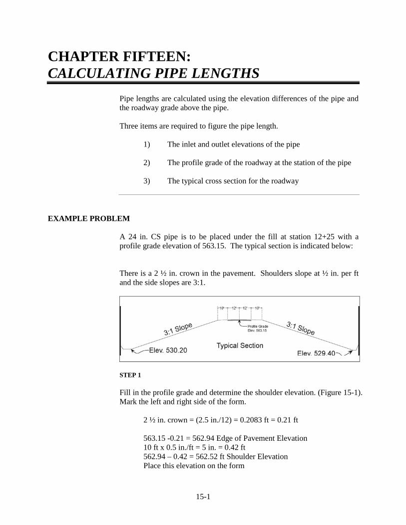
15-1
CHAPTER FIFTEEN: CALCULATING PIPE LENGTHS
Pipe lengths are calculated using the elevation differences of the pipe and the roadway grade above the pipe.
Three items are required to figure the pipe length. 1) The inlet and outlet elevations of the pipe 2) The profile grade of the roadway at the station of the pipe 3) The typical cross section for the roadway
EXAMPLE PROBLEM
A 24 in. CS pipe is to be placed under the fill at station 12+25 with a profile grade elevation of 563.15. The typical section is indicated below: There is a 2 ½ in. crown in the pavement. Shoulders slope at ½ in. per ft and the side slopes are 3:1.
STEP 1
Fill in the profile grade and determine the shoulder elevation. (Figure 15-1). Mark the left and right side of the form.
2 ½ in. crown = (2.5 in./12) = 0.2083 ft = 0.21 ft 563.15 -0.21 = 562.94 Edge of Pavement Elevation 10 ft x 0.5 in./ft = 5 in. = 0.42 ft 562.94 – 0.42 = 562.52 ft Shoulder Elevation Place this elevation on the form
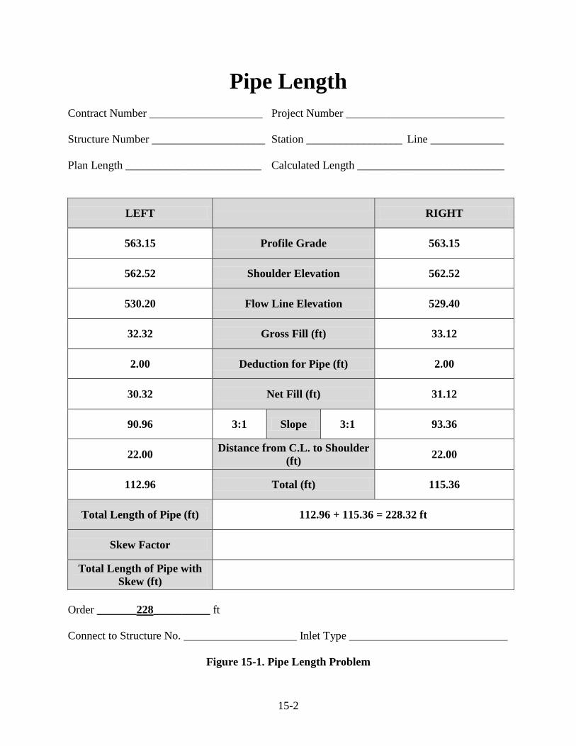
15-2
Pipe Length Contract Number ____________________ Project Number ____________________________ Structure Number ____________________ Station _________________ Line _____________ Plan Length ________________________ Calculated Length __________________________
LEFT
RIGHT
563.15 Profile Grade 563.15
562.52 Shoulder Elevation 562.52
530.20 Flow Line Elevation 529.40
32.32 Gross Fill (ft) 33.12
2.00 Deduction for Pipe (ft) 2.00
30.32 Net Fill (ft) 31.12
90.96 3:1 Slope 3:1 93.36
22.00 Distance from C.L. to Shoulder (ft) 22.00
112.96 Total (ft) 115.36
Total Length of Pipe (ft) 112.96 + 115.36 = 228.32 ft
Skew Factor
Total Length of Pipe with Skew (ft)
Order _______228__________ ft Connect to Structure No. ____________________ Inlet Type ____________________________
Figure 15-1. Pipe Length Problem
15-3
STEP 2
Place the inlet and outlet elevations on the proper sides of the form on the flowline elevation lines (inlet on the left and outlet on the right). Subtract this elevation from the shoulder elevation to obtain the gross fill.
inlet: 562.52- 530.20 = 32.32 ft outlet: 562.52 - 529.40 = 33.12 ft
STEP 3
Deduct the diameter of the pipe from the gross fill to obtain the net fill for each half of the roadway (24 in. pipe = 2 ft). Place this figure on the net fill line for each side.
inlet: 32.32 - 2.00 = 30.32 ft outlet: 33.12 - 2.00 = 31.12 ft
STEP 4
Place the rate of slope in the parentheses on the next line for the 3:1 slope. Multiply this times the net fill for each side:
Left = 30.32 ft x 3 = 90.96 ft Right = 31.12 ft x 3 = 93.36 ft
Place these values on the slope line for each side. These values represent the length of the pipe required for the point from the shoulder break to the end of the pipe for each side.
STEP 5
Place the distance from the centerline to the shoulder on the next line:
12 ft lane + 10 ft shoulder = 22 ft
This is the same for each side. Add this to the slope distance computed in Step 4:
Left = 90.96 ft + 22.00 ft = 112.96 ft Right = 93.36 ft + 22.00 ft = 115.36 ft

15-4
STEP 6 Add the two sides together for the total length: 112.96 ft + 115.36 ft = 228.32 ft Check for an increase in length due to pipe fall: 530.2 ft inlet elevation – 529.4 ft outlet elevation = 0.8 ft fall Use a2 + b2 = c2, where c a = 0.8 ft b = 228.32 ft c2 = (0.8)2 + (228.32)2
= 0.64 + 52130.022 = 52130.662
c = 228.32 ft (no substantial increase)
The amount of pipe to order is 228 ft. SKEW PIPES
For pipes on a skew, the calculations are the same as before except the length of pipe is calculated using the skew angle as follows:
length on skew = perpendicular length / cosine of the skew angle
EXAMPLE:
Using the previous example, all of the data is the same except the pipe is skewed 15 degrees to the left.
Plan View

15-5
The length of skew is calculated as follows: length of skew = 228.32/cos 15 degrees = 228.32/ 0.965925826
= 236.37 ft
Round to 237 ft. This is the length of pipe to order (Figure 15-2).
If riveted pipe is used, the pipe is required to be ordered in even 2 ft lengths. Spiral crimped seam pipe may be ordered to the nearest 1 ft length.
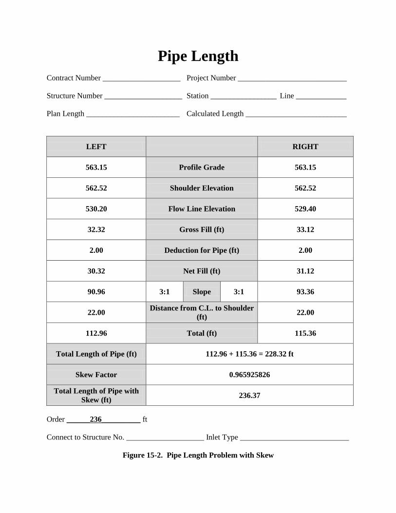
Pipe Length Contract Number ____________________ Project Number ____________________________ Structure Number ____________________ Station _________________ Line _____________ Plan Length ________________________ Calculated Length __________________________
LEFT
RIGHT
563.15 Profile Grade 563.15
562.52 Shoulder Elevation 562.52
530.20 Flow Line Elevation 529.40
32.32 Gross Fill (ft) 33.12
2.00 Deduction for Pipe (ft) 2.00
30.32 Net Fill (ft) 31.12
90.96 3:1 Slope 3:1 93.36
22.00 Distance from C.L. to Shoulder (ft) 22.00
112.96 Total (ft) 115.36
Total Length of Pipe (ft) 112.96 + 115.36 = 228.32 ft
Skew Factor 0.965925826
Total Length of Pipe with Skew (ft) 236.37
Order ______236__________ ft Connect to Structure No. ____________________ Inlet Type ____________________________
Figure 15-2. Pipe Length Problem with Skew

16 Multi-Plate Pipe Plates Bolts Plate Identification and Location Pipe-Arch Assembly Bolting
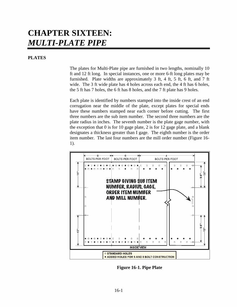
16-1
CHAPTER SIXTEEN: MULTI-PLATE PIPE PLATES
The plates for Multi-Plate pipe are furnished in two lengths, nominally 10 ft and 12 ft long. In special instances, one or more 6-ft long plates may be furnished. Plate widths are approximately 3 ft, 4 ft, 5 ft, 6 ft, and 7 ft wide. The 3 ft wide plate has 4 holes across each end, the 4 ft has 6 holes, the 5 ft has 7 holes, the 6 ft has 8 holes, and the 7 ft plate has 9 holes. Each plate is identified by numbers stamped into the inside crest of an end corrugation near the middle of the plate, except plates for special ends have these numbers stamped near each corner before cutting. The first three numbers are the sub item number. The second three numbers are the plate radius in inches. The seventh number is the plate gage number, with the exception that 0 is for 10 gage plate, 2 is for 12 gage plate, and a blank designates a thickness greater than I gage. The eighth number is the order item number. The last four numbers are the mill order number (Figure 16-1).
Figure 16-1. Pipe Plate
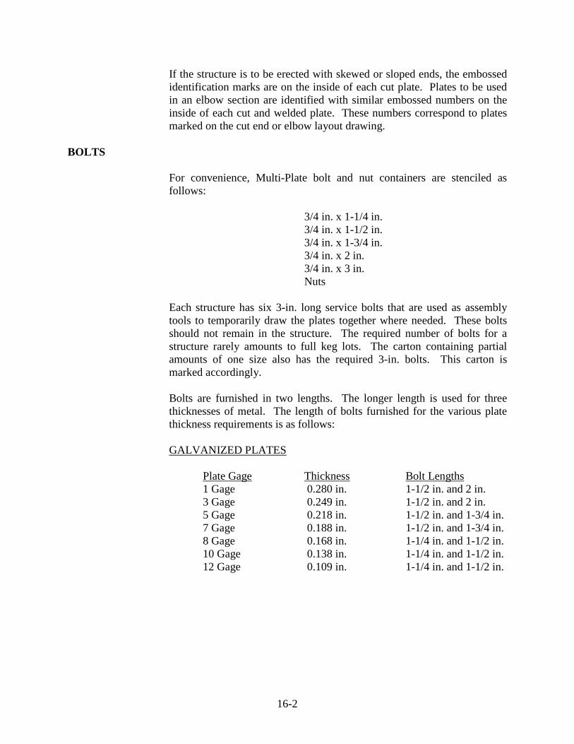
16-2
If the structure is to be erected with skewed or sloped ends, the embossed identification marks are on the inside of each cut plate. Plates to be used in an elbow section are identified with similar embossed numbers on the inside of each cut and welded plate. These numbers correspond to plates marked on the cut end or elbow layout drawing.
BOLTS
For convenience, Multi-Plate bolt and nut containers are stenciled as follows: 3/4 in. x 1-1/4 in. 3/4 in. x 1-1/2 in. 3/4 in. x 1-3/4 in. 3/4 in. x 2 in. 3/4 in. x 3 in. Nuts Each structure has six 3-in. long service bolts that are used as assembly tools to temporarily draw the plates together where needed. These bolts should not remain in the structure. The required number of bolts for a structure rarely amounts to full keg lots. The carton containing partial amounts of one size also has the required 3-in. bolts. This carton is marked accordingly.
Bolts are furnished in two lengths. The longer length is used for three thicknesses of metal. The length of bolts furnished for the various plate thickness requirements is as follows:
GALVANIZED PLATES
Plate Gage Thickness Bolt Lengths 1 Gage 0.280 in. 1-1/2 in. and 2 in. 3 Gage 0.249 in. 1-1/2 in. and 2 in. 5 Gage 0.218 in. 1-1/2 in. and 1-3/4 in. 7 Gage 0.188 in. 1-1/2 in. and 1-3/4 in. 8 Gage 0.168 in. 1-1/4 in. and 1-1/2 in. 10 Gage 0.138 in. 1-1/4 in. and 1-1/2 in. 12 Gage 0.109 in. 1-1/4 in. and 1-1/2 in.

16-3
ASPHALT COATED PLATES Plate Gage Thickness Bolt Lengths 1 Gage 0.280 in. 1-3/4 in. and 2 in. 3 Gage 0.249 in. 1-3/4 in. and 2 in. 5 Gage 0.218 in. 1-3/4 in. and 2 in. 7 Gage 0.188 in. 1-3/4 in. and 2 in. 8 Gage 0.168 in. 1-1/2 in. and 1-3/4 in. 10 Gage 0.138 in. 1-1/2 in. and 1-3/4 in. 12 Gage 0.109 in. 1-1/2 in. and 1-3/4 in.
The longer of the two bolt lengths is placed in the corners of the plates where three thicknesses of metal overlap and in the hole next to the corner in the longitudinal seam. The shorter of the two bolts is placed where only two thicknesses of metal overlap (Figure 16-2).
Figure 16-2. Bolt Placement

16-4
PLATE IDENTIFICATION AND LOCATION
The various widths of plates are located in the barrel in accordance with the plate layout drawings. The numbers appearing in the barrel area or on the plates are the number of bolt holes across the end of each plate. The line layout and/or plate layout shows total 10-ft and 12-ft-long rings making up the structure. The beginning and ending rings are indicated in Figure 16-3 for square end structures and these structures contain combinations of 10-ft and 12-ft rings required to obtain the proper plate stagger. Special plates in cut end structures are shown on the plate layout together with the necessary 10-ft and 12-ft long plates required to obtain the proper seam stagger in the barrel. Intermediate barrel rings contain plates which are all the same length. For cut plates and elbow cut and welded plates, the numbers appear on the plate layout corresponding to the embossed numbers on the plates themselves.

16-5
Figure 16-3. Typical Barrel End Views (looking downstream)

16-6
PIPE-ARCH ASSEMBLY
The pipe-arch is assembled in three stages as follows:
1) bottom 2) corners 3) top
The bottom (invert) plates are assembled by laying the first bottom plate at the outlet end, then placing each succeeding plate in the longitudinal row so the plate laps one corrugation of the preceding plate (Figure 11-2). The invert plates are positioned accurately with a stringline before tightening the bolts. The two corner bolt holes (Figure 16-4) are different. One bolt is close to the plate edge and the other bolt is set in from the plate edge. When beginning construction, the corner bolt hole pattern is required to match the pattern shown on the plate layout drawing.
Figure 16-4. Inside View of Pipe
After several invert plates have been laid down, aligned, and bolts tightened, the corner plates are attached to each side at the outlet end. The corner plate may lap either inside or outside the invert plates (Figure 16-4). Also, each additional corner plate is required to lap over the preceding plate by one corrugation.
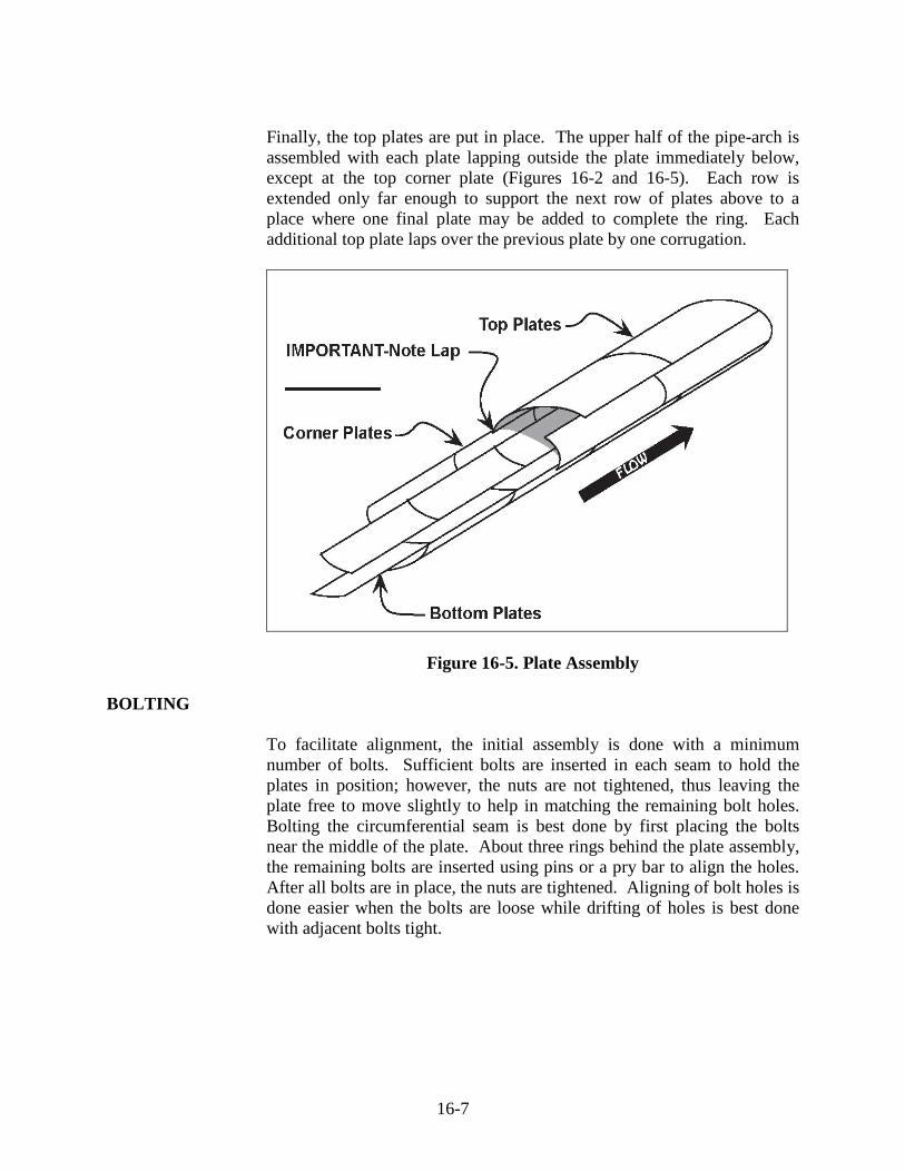
16-7
Finally, the top plates are put in place. The upper half of the pipe-arch is assembled with each plate lapping outside the plate immediately below, except at the top corner plate (Figures 16-2 and 16-5). Each row is extended only far enough to support the next row of plates above to a place where one final plate may be added to complete the ring. Each additional top plate laps over the previous plate by one corrugation.
Figure 16-5. Plate Assembly BOLTING
To facilitate alignment, the initial assembly is done with a minimum number of bolts. Sufficient bolts are inserted in each seam to hold the plates in position; however, the nuts are not tightened, thus leaving the plate free to move slightly to help in matching the remaining bolt holes. Bolting the circumferential seam is best done by first placing the bolts near the middle of the plate. About three rings behind the plate assembly, the remaining bolts are inserted using pins or a pry bar to align the holes. After all bolts are in place, the nuts are tightened. Aligning of bolt holes is done easier when the bolts are loose while drifting of holes is best done with adjacent bolts tight.

16-8
Sometimes, tightening all of the bottom plate bolts as the bottom is assembled is desirable. If this procedure is done, certain plates are required to be properly aligned before tightening the bolts. Corner and top plates are always assembled with as few bolts as possible while initially assembling the structure. The recommended range for bolt torque is between 100 and 300 foot-pounds. A balanced progression of tightening is maintained with respect to the axis of the structure, to prevent a spiraling tendency.