Embed Size (px)
Citation preview

® CONSULMET
1
Lwazi Mthwana
11th DMS Symposium
February 2014

Abstract
Who is Consulmet
Introduction
Test-work
Design Criteria
Plant Flow Description
Commissioning Experiences
Conclusion
Discussion
2

Gecamines Kamfundwa Copper Beneficiation plant was commissioned between September and November 2013
This paper discusses the basic principles of DMS commissioning in a copper application
Overview of initial test-work and design criteria
Challenges that were experienced
Discussion focuses on the following items: ◦ Pressure Control
◦ Effect of Medium Density on Cyclone Performance (cut point, yield and grade)
◦ Power and water supply
◦ FeSi Losses
3

Consulmet (Pty) Limited specialises in the application of modular recovery solutions for the mining sector of the minerals industries, predominantly on the African continent.
Consulmet provides a fully comprehensive service comprising of the design, construction, commissioning and trouble-shooting of mineral processing plants
Design offices in Johannesburg and Cape Town
Fabrication workshop in Klerksdorp
4

Kamfundwa Plant is located in Kambove in the Democratic Republic of Congo
300 tph Head Feed, 150 tph DMS
Produce 15% concentrate from 2% copper in malachite-rich ore
The concentrate would be further
processed in Gecamines existing
facilities
5

Particle Size Distribution for sizing equipment
Densimetric analysis to determine whether DMS was a suitable method of separation
Assaying to determine copper grade of feed material, expected grade of concentrate and tailings
6

DMS was a suitable method of separation
The optimum recovery occurs at a cut point density of 2.72t/m3
7
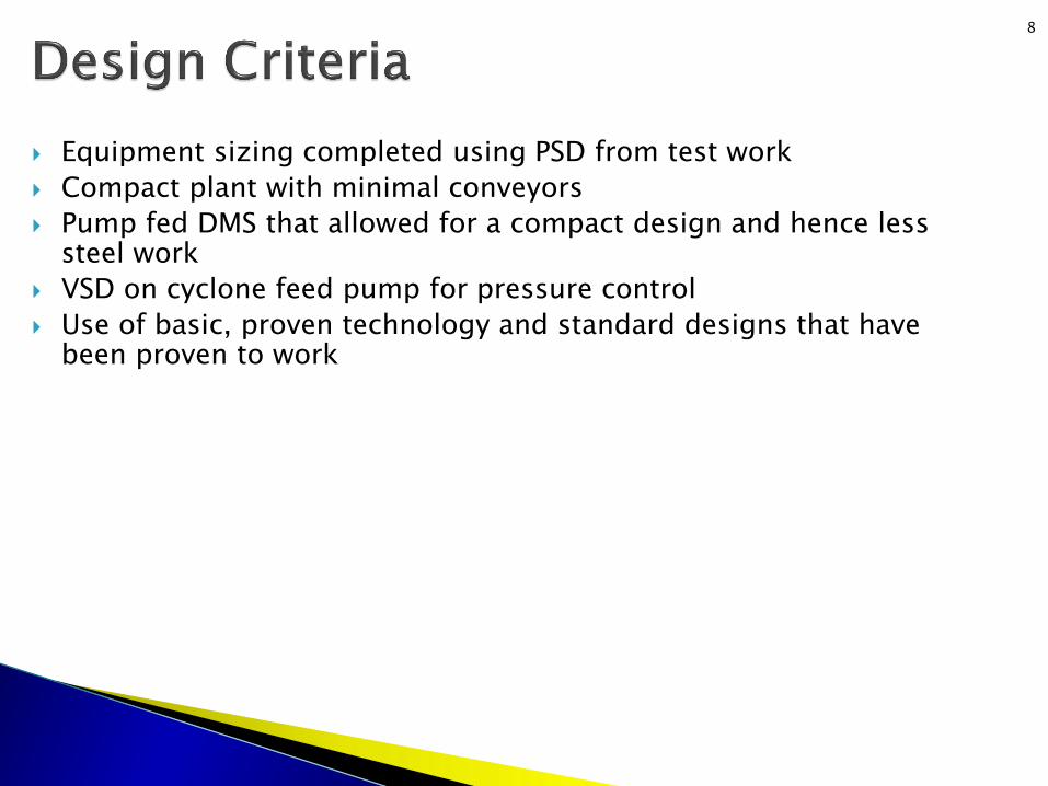
Equipment sizing completed using PSD from test work
Compact plant with minimal conveyors
Pump fed DMS that allowed for a compact design and hence less steel work
VSD on cyclone feed pump for pressure control
Use of basic, proven technology and standard designs that have been proven to work
8

9
Mineralogy
Value (%)
Copper content in ROM 2 – 2,5
Malachite 85
Pseudomalachite& Chrisocolla 10- 15
Heterogenite 0,8 – 2
Impurities Non magnetic
Operating Schedule
Value
Operating hours per day 20
Number of operating days per year 360
Total operating hours per year 7200
Availability of plant (%) 82
DMS Circuit
Value Units
Feed surge bin capacity 115 Tons Total
Total DMS feed as % of ROM 50 – 60 %
DMS feed rate 150 tph
Feed prep screen cut size 1 mm
Cyclone size 510 mm
Number of cyclones in module 2
Nominal medium : ore ratio 6: 1
Cyclone cut point density 2.72 t/m3
Cyclone operating head 15 D
Design yield to sinks 9 – 12.5 %

GRIZZLY JAW
CRUSHER
SCRUBBER SIZING SCREEN
CONE CRUSHER
DMS
SPIRALS
PRODUCT
Plant Feed
-1mm Effluent
-100mm
+100mm
+19mm
-19+1mm
-1mm
Tailings
Slimes
10

11

12
PI
PI
SINKS -19 +1mm
150 TPH
-19 +1mm
201-CHU-001
DMS FEED (-19 +1MM)
FROM 101-CVR-010
A100-PFD-101
201-SCR-001
201-UPN-001
201-MXB-001
201-PMP-001
201-CYC-001 A
2
4
3
5 201-CYC-001 B
201-SCR-002
201-SCR-003
201-SCR-004
201-UPN-002
10 21
201-CHU-002
7
8
201-SMP-001
201-SMP-002
201-PMP-002 201-PMP-003
201-PMP-004
201-PMP-006
201-MAG-001
201-DMG-001
201-SMP-003
201-PMP-005
201-SMP-004
201-DMC-001
M
M
M
MM
M
M
M
M
PROCESS WATER
FROM A101
A100-PFD-101
25
22
15
17
16
26
DMS SINKS TO
101-CVR-007 (-19+1mm)
A100-PFD-10123
201-SCR-005
6
M
FLOATS -19 +1mm
201-CHU-003
DMS FLOATS TO
101-CVR-008 (-19+1mm)
A100-PFD-101
24
PI
13 14
12
9
2019
18
DMS EFFLUENT
201-UPN-003
201-SPL-001 201-SPL-002
201-DST-001
201-DNS-001 B
201-DNS-001 C
201-DNS-001 A
201-DST-002
11
R/LINED
R/LINED
R/LINED
R/LINED
R/LINED R/LINED
R/LINED
R/LINED
CERAMIC
LINED
R/LINED
GLAND
WATER
FIELD MOUNTED
CONTROL PANEL
160MM ORIFICE C/W
REPLACEABLE
145, 150 &155MM
ORIFICE PLATES
PI PI
PI
VSD
27
28
FLOOD
BOX
CRAWL BEAM
CYCLONE FEED PUMP
MAINTENANCE
201-HST-002
BOX
MAGNET
CRAWL BEAM CIRC.
MEDIUM PUMP
MAINTENANCE
201-HST-003
COMPRESSOR
201-CMP-001
MOTOR CONTROL
CENTRE (MCC)
(A201)
1
29
FR
ON
T E
ND
DM
S
FRONT END
DMS
FRONT END
DMS
FRONT END
DMS
FRONT END
DMS
NOTE 5
PT
®CONSULMET

13

Cyclone Pressure ◦ VSD driven cyclone feed pump
◦ Speed of VSD was adjusted to maintain the mixing box level (78% to 90% VSD speed)
◦ Pump operated at a range of 12.5D to 14D
◦ Pressure on both cyclones were the same during operation
◦ No fluctuation of pressure during normal operation
◦ No significant changes noted in the efficiency of the separation as a result of change in cyclone pressure
14

Density ◦ Initial start of plant was with a correct medium of specific gravity
2.65
◦ Tracer Test showed a cut point of 3.01 t/m3 and a yield of 6.7%, producing a product of 45% grade
◦ The grade was high and yield was low
◦ Medium density was dropped incrementally. The results showed a drop in cut point and an increase in yield
Medium Density Cut Point (t/m3) Yield (%)
2.65 3.01 6.7
2.6 2.96 8.1
2.55 2.87 9.4
2.5 2.83 10.2
2.45 2.78 11.1
2.4 2.68 12.3
15

Initial Set Up
Medium SG 2.65
Cut Point 3.01 t/m3
Yield 6.7 %
Product Tons 10.0 tph
Grade 45 %
Final Set Up
Medium SG 2.40
Cut Point 2.68 t/m3
Yield 12.3 %
Product Tons 18.5 tph
Grade 31 %
Density
16

Density Control and Densification ◦ Float screen spray water splashed into drain side of underpan,
causing dilution of correct media
◦ Rate of densification increased by using two densifiers. One densifier was always on standby
Drain side to correct medium sump
Wash side To dilute medium sump
17

Process Water Supply ◦ Process water supply pump was powered by local power
◦ Low power availability. Loss of power occurred 2 to 3 times a day for a period of no less than hour
◦ Every time there was a power failure, the plant had to be stopped and the DMS had to be flushed and brought to a gentle stop
◦ Alertness at DMS was needed since time was a factor. Level of process water dam was closely monitored
◦ Frequency of start-stop provided good training for DMS operators
18

FeSi Consumption ◦ Start-stop of DMS lead to high FeSi consumption as FeSi was
lost during flushing of pipelines and pumps.
◦ FeSi was lost when washing FeSi from the floor back into the circuit
◦ Compressed air was used keep FeSi in suspension in the CM sump while plant was idling. CM sump had to flushed after 12 hours of idling to prevent choke-up
◦ No significant FeSi losses were caused by the magnetic separator
◦ High pressure on sinks and float screens spray water assisted with FeSi recovery
19

DMS Start-Up ◦ Initially, the DMS took over 1 hour to start-up. The time was
used to attain the set point density in the correct media
◦ Upon shut-down, it became an adopted operating philosophy to wash in the drained FeSi back into the correct medium sump
◦ This assisted in reducing start-up time to less than an hour
20

Test work showed that no significant increase in grade (30%) occurred at a cut point density above 2.7 t/m3. In practise, the grade at a cut point of 3.01 t/m3 was 45%
By dropping the cut point density from 3.01 t/m3 to 2.68 t/m3, the yield was increased by 84%
A lower density increases utilisation of the plant. Decrease in downtime is due to steadier control of density
Multiple hoses for washing in FeSi assist in reducing DMS start-up time
VSD driven cyclone feed pump and 2-way Y piece distributor provides efficient pressure control
21

The DMS process can be effectively used to upgrade the concentration of copper from malachite-rich ore
Product contained 31% copper, and discard contained 0.5% copper
22
31% Copper 0.5% Copper

The commissioning of Kamfundwa Copper Beneficiation Plant was a success, with no major problems as a result of the design, construction or operation
The success can largely be attributed to the use of proven technology and designs
The application of basic principles and technology can still be the key factor to a successful project
23

24