Embed Size (px)
Citation preview
Job No. Sheet No. Rev.
Job Title
XX
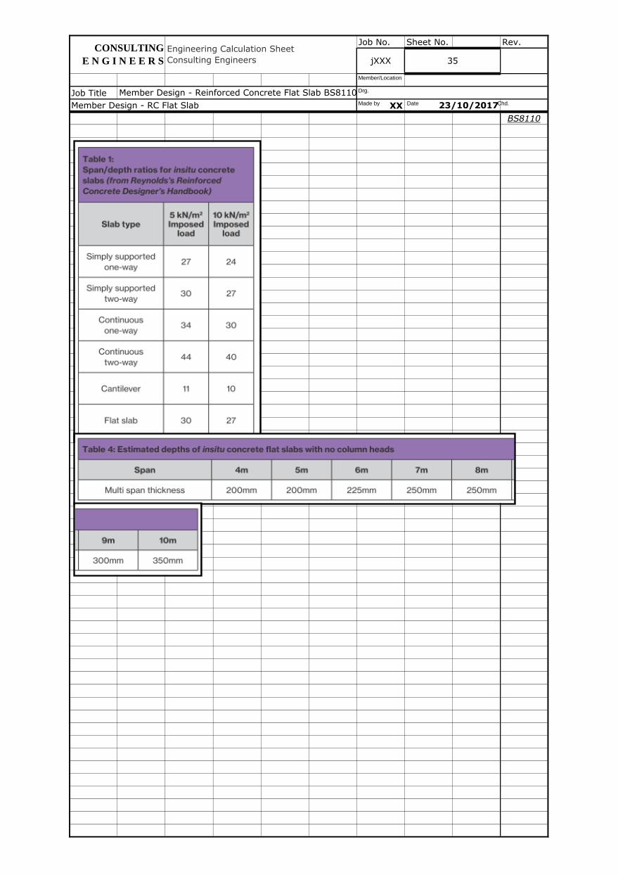
BS8110
Material Properties
Characteristic strength of concrete, fcu / fc' (fcu ≤ 60N/mm2; HSC N/A) 40 32 N/mm
2 OK
Yield strength of longitudinal steel, fy 460 N/mm2
Yield strength of shear link steel, fyv 460 N/mm2
Type of concrete and density, rc 24 kN/m3
Slab Parameters
Shorter span (defined as in x), lx (number affects slab lx moments, shear, deflection criteria; edge beam lx moments, shear, effective width, section support conditions)8.200 m
Longer span (defined as in y), ly (number affects slab ly moments, shear, deflection criteria; edge beam ly moments, shear, effective width, section support conditions)11.000 m OK
Slab support conditions (affects moments, shear, deflection criteria)
Panel (affects moments, shear, supports for edge beam)
Overall slab depth, hslab (l/27 s/s; l/36 cont; l/7-l/10 cant) 250 mm
Cover to all reinforcement, cover (usually MAX(25, f) internal; 40 external) 25 mm
Effective depth to sagging steel in x, dx,s = hslab - cover - fsy - fsx/2 199 mm
Effective depth to CS sagging steel in y, dy,s,c = hslab + ddp - cover - fsy/2 467 mm
Effective depth to MS sagging steel in y, dy,s,m = hslab - cover - fsy/2 217 mm
Effective depth to CS hogging steel in x, dx,h,c = hslab + ddp - cover - flink - fhy - fhx/2 439 mm
Effective depth to MS hogging steel in x, dx,h,m = hslab - cover - flink - fhy - fhx/2 189 mm
Effective depth to CS hogging steel in y, dy,h,c = hslab +ddp - cover - flink - fhy/2 455 mm
Effective depth to MS hogging steel in y, dy,h,m = hslab - cover - flink - fhy/2 205 mm
Note that the column strip reinforcement diameters have been assumed for the effective depth calcs,
this effectively enforcing the simplicity of common planes of reinforcement for each of the layers.
Note that d dp only incorporated in the above column strip hogging effective depth calcs if w dp >= l x /3.
Note that d dp only incorporated in the above column strip sagging effective depth calcs if w dp >= l x /3 and banded.
MS CS
Sagging steel reinforcement diameter in x, fsx 12 20 mm
Sagging steel reinforcement pitch for resistance in x, psx 150 150 mm
Sagging steel area provided in x, As,prov,x,s = (p.fsx2/4)/psx 754 2094 mm
2/m
Sagging steel reinforcement diameter in y, fsy 16 16 mm
Sagging steel reinforcement pitch for resistance in y, psy 150 150 mm
Sagging steel area provided in y, As,prov,y,s = (p.fsy2/4)/psy 1340 1340 mm
2/m
Hogging steel reinforcement diameter in x, fhx 10 16 mm
Hogging steel reinforcement pitch for resistance in x, phx 150 150 mm
Hogging steel area provided in x, As,prov,x,h = (p.fhx2/4)/phx 524 1340 mm
2/m
Hogging steel reinforcement diameter in y, fhy 12 16 mm
Hogging steel reinforcement pitch for resistance in y, phy 150 150 mm
Hogging steel area provided in y, As,prov,y,h = (p.fhy2/4)/phy 754 1340 mm
2/m
Shear link diameter, flink 12 mm
Pitch of links for first / second shear perimeters 200 200 mm
Number of links for first / second shear perimeters, nl,2/3143 197 105 105
Area provided by all links for first / second shear perimeters, Asv,prov,2/3 = nl,2/3.p.flink2/416173 22280 11875 11875 mm
2
Pitch of links for third / fourth shear perimeters 300 300 mm
Number of links for third / fourth shear perimeters, nl,4/5125 152 42 42
Area provided by all links for third / fourth shear perimeters, Asv,prov,4/5 = nl,4/5.p.flink2/414137 17191 4750 4750 mm
2
Slab Drop and Slab Band and Column Head Concepts Note
Note slab drops (valid only if w dp ≥ l x /3) enhance the punching shear capacity and the column strip
hogging moment capacity in x and y enabling thinner slabs beyond the drops.
Slab bands differ from slab drops in the sense that the column strip sagging moment capacity in y
(but not in x) is also enhanced on top of the benefits of slab drops.
Column heads enhance punching shear capacity only.
Member Design - RC Flat Slab 23/10/2017
Engineering Calculation Sheet
Consulting Engineers jXXX 1
CONSULTING
E N G I N E E R S
Member Design - Reinforced Concrete Flat Slab BS8110, ACI318 v2017.01.xlsmMade by Date Chd.
Drg.
Member/Location
Job No. Sheet No. Rev.
Job Title
XX
BS8110
Slab Loading (Plan Loading)
(Internal elev load must be checked on effective widths [span/(5 or 7.14)] within slab depth)
Live load, LL 2.50 kPa
Superimposed dead load, SDLplan 1.50 kPa
Dead load of slab, DL = hslab.rc + [wdp2 or wdp.ly]/(lx.ly).ddp.rc 8.05 kPa
ULS slab loading, wULS,slab (a.k.a. n) = 1.4(DL+SDLplan)+1.6LL 18.67 17.37 kPa NOT OK
Edge Loading (Elevation Loading)
Superimposed dead load on edge beam spanning in x direction, SDLelev,x 0.00 kN/m
Superimposed dead load on edge beam spanning in y direction, SDLelev,y 0.00 kN/m
Column Parameters
Section type
Depth, h (rectangular) or diameter, D (circular) 600 mm
Width, b (rectangular) or N/A (circular) 1500 mm
Limitations of Moment Transfer Into Edge Column
Width of edge column strip for moment transfer, be,a 1500 mm
Slab Drop and Slab Band Parameters
Slab drop depth, ddp (excluding slab depth hslab) 250 mm
Slab drop width, wdp (usually >= lx/3 when employed) 2.800 m OK
Note that the self weight of the slab drop is accounted in the design of the slab.
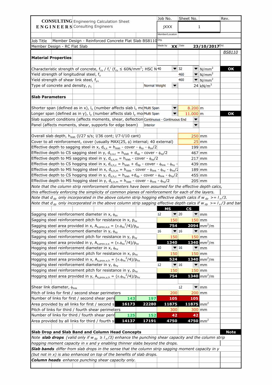
Column Head Parameters
Column head effective depth (rectangular), lh,h = MIN (lh0,h, lhmax,h) or effective diameter (circular), lh,D = MIN (lh0,D, lhmax,D)600 mm
Column head effective width (rectangular), lh,b = MIN (lh0,b, lhmax,b) or N/A (circular) 1500 mm
Column head dimension beyond column face, lhface 0 mm
Column head depth, dh 0 mm
Column head actual depth (rectangular), lh0,h = h + (1 or 2).lhface or actual diameter (circular), lh0,D = D + (1 or 2).lhface600 mm
Column head actual width (rectangular), lh0,b = b + (1 or 2).lhface or N/A (circular)1500 mm
Column head maximum depth (rectangular), lhmax,h = h + 2.(dh-40) or maximum diameter (circular), lhmax,D = D + 2.(dh-40)520 mm
Column head maximum width (rectangular), lhmax,b = b + 2.(dh-40) or N/A (circular)1420 mm
Note that the self weight of the column head is to be accounted in the design of the column, not the slab.
Member Design - Reinforced Concrete Flat Slab BS8110, ACI318 v2017.01.xlsm
CONSULTING
E N G I N E E R S 2
Member Design - RC Flat Slab 23/10/2017
Engineering Calculation Sheet
Consulting Engineers jXXX
Made by Date Chd.
Drg.
Member/Location
lhface
Job No. Sheet No. Rev.
Job Title
XX
BS8110
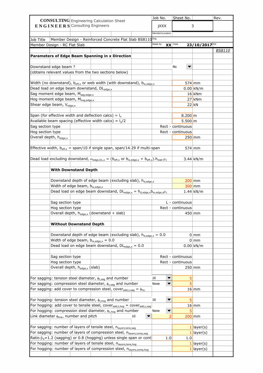
Parameters of Edge Beam Spanning in x Direction
Downstand edge beam ?
(obtains relevant values from the two sections below)
Width (no downstand), beff,x or web width (with downstand), bw,edge,x 574 mm
Dead load on edge beam downstand, DLedge,x 0.00 kN/m
Sag moment edge beam, Msag,edge,x 16 kNm
Hog moment edge beam, Mhog,edge,x 27 kNm
Shear edge beam, Vedge,x 22 kN
Span (for effective width and deflection calcs) = lx 8.200 m
Available beam spacing (effective width calcs) = ly/2 5.500 m
Sag section type Rect - continuous
Hog section type Rect - continuous
Overall depth, hedge,x 250 mm
Effective width, beff,x = span/10 if single span, span/14.29 if multi-span 574 mm
Dead load excluding downstand, wedge,DL,x = (beff,x or bw,edge,x + beff,x).hslab.rc 3.44 kN/m
With Downstand Depth
Downstand depth of edge beam (excluding slab), hd,edge,x 200 mm
Width of edge beam, bw,edge,x 300 mm
Dead load on edge beam downstand, DLedge,x = hd,edge,xbw,edge,xrc 1.44 kN/m
Sag section type L - continuous
Hog section type Rect - continuous
Overall depth, hedge,x (downstand + slab) 450 mm
Without Downstand Depth
Downstand depth of edge beam (excluding slab), hd,edge,x = 0.0 0 mm
Width of edge beam, bw,edge,x = 0.0 0 mm
Dead load on edge beam downstand, DLedge,x = 0.0 0.00 kN/m
Sag section type Rect - continuous
Hog section type Rect - continuous
Overall depth, hedge,x (slab) 250 mm
For sagging: tension steel diameter, ft,sag and number 5
For sagging: compression steel diameter, fc,sag and number 5
For sagging: add cover to compression steel, coveradd,c,sag = fhy 16 mm
For hogging: tension steel diameter, ft,hog and number 5
For hogging: add cover to tensile steel, coveradd,t,hog = coveradd,c,sag 16 mm
For hogging: compression steel diameter, fc,hog and number 5
Link diameter flink, number and pitch 2 200 mm
For sagging: number of layers of tensile steel, nlayers,tens,sag 1 layer(s)
For sagging: number of layers of compression steel, nlayers,comp,sag 1 layer(s)
Ratio bb=1.2 (sagging) or 0.8 (hogging) unless single span or continuous elastic1.0 1.0
For hogging: number of layers of tensile steel, nlayers,tens,hog 1 layer(s)
For hogging: number of layers of compression steel, nlayers,comp,hog 1 layer(s)
Member Design - RC Flat Slab 23/10/2017
jXXX
CONSULTING
E N G I N E E R S 3
Engineering Calculation Sheet
Consulting Engineers
Member Design - Reinforced Concrete Flat Slab BS8110, ACI318 v2017.01.xlsmMade by Date Chd.
Drg.
Member/Location
Job No. Sheet No. Rev.
Job Title
XX
BS8110
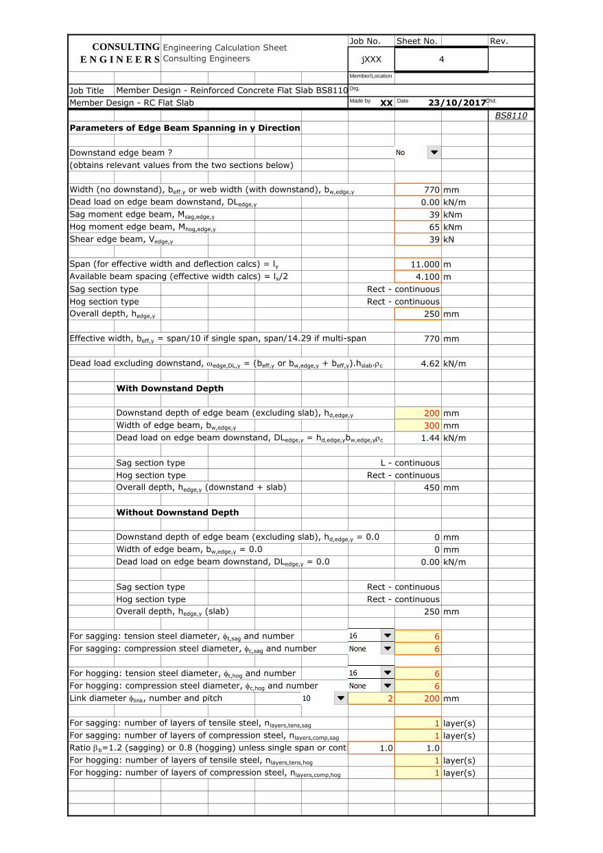
Parameters of Edge Beam Spanning in y Direction
Downstand edge beam ?
(obtains relevant values from the two sections below)
Width (no downstand), beff.y or web width (with downstand), bw,edge,y 770 mm
Dead load on edge beam downstand, DLedge,y 0.00 kN/m
Sag moment edge beam, Msag,edge,y 39 kNm
Hog moment edge beam, Mhog,edge,y 65 kNm
Shear edge beam, Vedge,y 39 kN
Span (for effective width and deflection calcs) = ly 11.000 m
Available beam spacing (effective width calcs) = lx/2 4.100 m
Sag section type Rect - continuous
Hog section type Rect - continuous
Overall depth, hedge,y 250 mm
Effective width, beff,y = span/10 if single span, span/14.29 if multi-span 770 mm
Dead load excluding downstand, wedge,DL,y = (beff,y or bw,edge,y + beff,y).hslab.rc 4.62 kN/m
With Downstand Depth
Downstand depth of edge beam (excluding slab), hd,edge,y 200 mm
Width of edge beam, bw,edge,y 300 mm
Dead load on edge beam downstand, DLedge,y = hd,edge,ybw,edge,yrc 1.44 kN/m
Sag section type L - continuous
Hog section type Rect - continuous
Overall depth, hedge,y (downstand + slab) 450 mm
Without Downstand Depth
Downstand depth of edge beam (excluding slab), hd,edge,y = 0.0 0 mm
Width of edge beam, bw,edge,y = 0.0 0 mm
Dead load on edge beam downstand, DLedge,y = 0.0 0.00 kN/m
Sag section type Rect - continuous
Hog section type Rect - continuous
Overall depth, hedge,y (slab) 250 mm
For sagging: tension steel diameter, ft,sag and number 6
For sagging: compression steel diameter, fc,sag and number 6
For hogging: tension steel diameter, ft,hog and number 6
For hogging: compression steel diameter, fc,hog and number 6
Link diameter flink, number and pitch 2 200 mm
For sagging: number of layers of tensile steel, nlayers,tens,sag 1 layer(s)
For sagging: number of layers of compression steel, nlayers,comp,sag 1 layer(s)
Ratio bb=1.2 (sagging) or 0.8 (hogging) unless single span or continuous elastic1.0 1.0
For hogging: number of layers of tensile steel, nlayers,tens,hog 1 layer(s)
For hogging: number of layers of compression steel, nlayers,comp,hog 1 layer(s)
Member Design - RC Flat Slab
Member Design - Reinforced Concrete Flat Slab BS8110, ACI318 v2017.01.xlsm
23/10/2017
Engineering Calculation Sheet
Consulting Engineers
CONSULTING
E N G I N E E R S 4jXXX
Made by Date Chd.
Drg.
Member/Location
Job No. Sheet No. Rev.
Job Title
XX
BS8110
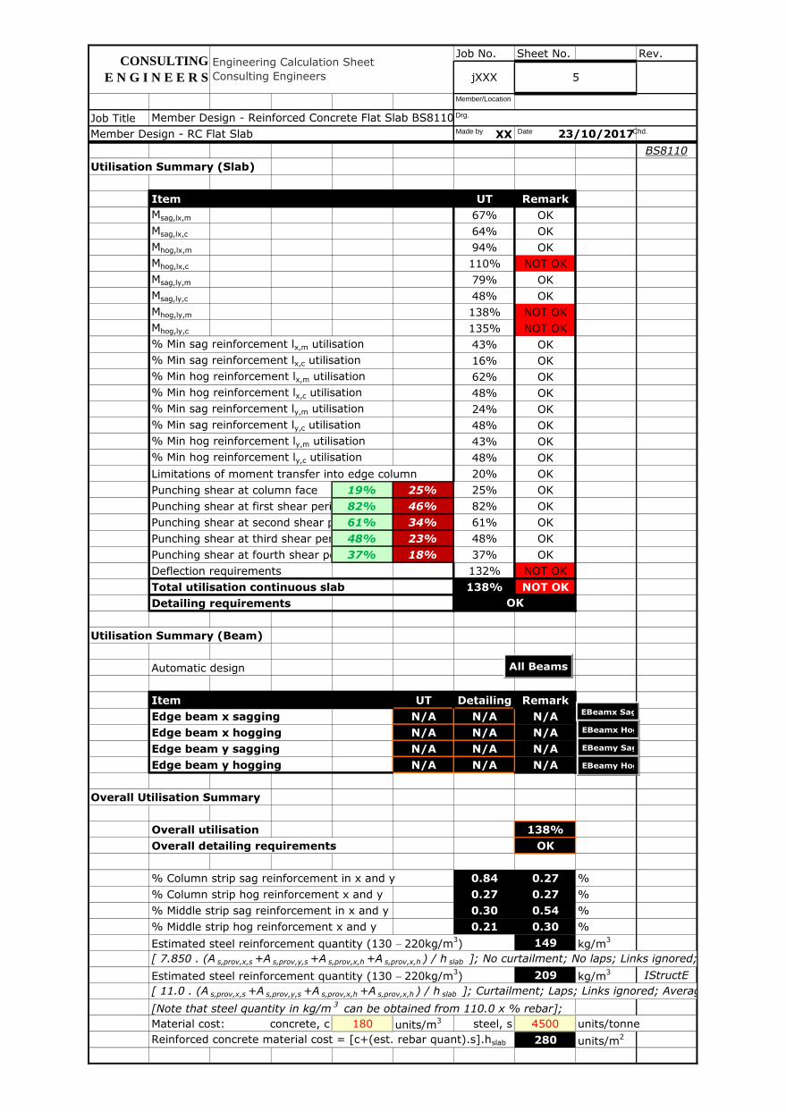
Utilisation Summary (Slab)
Item UT Remark
Msag,lx,m 67% OK
Msag,lx,c 64% OK
Mhog,lx,m 94% OK
Mhog,lx,c 110% NOT OK
Msag,ly,m 79% OK
Msag,ly,c 48% OK
Mhog,ly,m 138% NOT OK
Mhog,ly,c 135% NOT OK
% Min sag reinforcement lx,m utilisation 43% OK
% Min sag reinforcement lx,c utilisation 16% OK
% Min hog reinforcement lx,m utilisation 62% OK
% Min hog reinforcement lx,c utilisation 48% OK
% Min sag reinforcement ly,m utilisation 24% OK
% Min sag reinforcement ly,c utilisation 48% OK
% Min hog reinforcement ly,m utilisation 43% OK
% Min hog reinforcement ly,c utilisation 48% OK
Limitations of moment transfer into edge column 20% OK
Punching shear at column face 19% 25% 25% OK
Punching shear at first shear perimeter82% 46% 82% OK
Punching shear at second shear perimeter61% 34% 61% OK
Punching shear at third shear perimeter48% 23% 48% OK
Punching shear at fourth shear perimeter37% 18% 37% OK
Deflection requirements 132% NOT OK
Total utilisation continuous slab 138% NOT OK
Detailing requirements
Utilisation Summary (Beam)
Automatic design
Item UT Detailing Remark
Edge beam x sagging N/A N/A N/A
Edge beam x hogging N/A N/A N/A
Edge beam y sagging N/A N/A N/A
Edge beam y hogging N/A N/A N/A
Overall Utilisation Summary
Overall utilisation 138%
Overall detailing requirements OK
% Column strip sag reinforcement in x and y 0.84 0.27 %
% Column strip hog reinforcement x and y 0.27 0.27 %
% Middle strip sag reinforcement in x and y 0.30 0.54 %
% Middle strip hog reinforcement x and y 0.21 0.30 %
Estimated steel reinforcement quantity (130 - 220kg/m3) 149 kg/m
3
[ 7.850 . (A s,prov,x,s +A s,prov,y,s +A s,prov,x,h +A s,prov,x,h ) / h slab ]; No curtailment; No laps; Links ignored; Average col and mid strips;
Estimated steel reinforcement quantity (130 - 220kg/m3) 209 kg/m
3 IStructE
[ 11.0 . (A s,prov,x,s +A s,prov,y,s +A s,prov,x,h +A s,prov,x,h ) / h slab ]; Curtailment; Laps; Links ignored; Average col and mid strips;
[Note that steel quantity in kg/m3 can be obtained from 110.0 x % rebar];
Material cost: concrete, c 180 units/m3 steel, s 4500 units/tonne
Reinforced concrete material cost = [c+(est. rebar quant).s].hslab 280 units/m2
OK
Engineering Calculation Sheet
Consulting Engineers
CONSULTING
E N G I N E E R S jXXX 5
Member Design - RC Flat Slab
Member Design - Reinforced Concrete Flat Slab BS8110, ACI318 v2017.01.xlsm
23/10/2017Made by Date Chd.
Drg.
Member/Location
All Beams
EBeamx Sag
EBeamx Hog
EBeamy Sag
EBeamy Hog
Job No. Sheet No. Rev.
Job Title
XX
BS8110
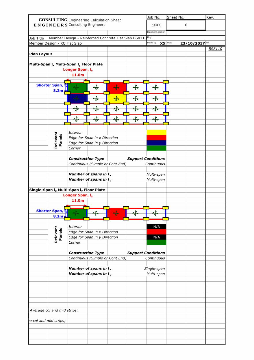
Plan Layout
Multi-Span lx Multi-Span ly Floor Plate
Longer Span, ly
11.0m
Shorter Span, lx
8.2m
Interior
Edge for Span in x Direction
Edge for Span in y Direction
Corner
Construction Type Support Conditions
Continuous (Simple or Cont End) Continuous
Number of spans in l x Multi-span
Number of spans in l y Multi-span
Single-Span lx Multi-Span ly Floor Plate
Longer Span, ly
11.0m
Shorter Span, lx
8.2m
Interior N/A
Edge for Span in x Direction
Edge for Span in y Direction N/A
Corner
Construction Type Support Conditions
Continuous (Simple or Cont End) Continuous
Number of spans in l x Single-span
Number of spans in l y Multi-span
[ 7.850 . (A s,prov,x,s +A s,prov,y,s +A s,prov,x,h +A s,prov,x,h ) / h slab ]; No curtailment; No laps; Links ignored; Average col and mid strips;
[ 11.0 . (A s,prov,x,s +A s,prov,y,s +A s,prov,x,h +A s,prov,x,h ) / h slab ]; Curtailment; Laps; Links ignored; Average col and mid strips;
Rele
van
t
Pan
els
Member Design - RC Flat Slab 23/10/2017
Rele
van
t
Pan
els
CONSULTING
E N G I N E E R S jXXX 6
Engineering Calculation Sheet
Consulting Engineers
Member Design - Reinforced Concrete Flat Slab BS8110, ACI318 v2017.01.xlsmMade by Date Chd.
Drg.
Member/Location
Job No. Sheet No. Rev.
Job Title
XX
BS8110
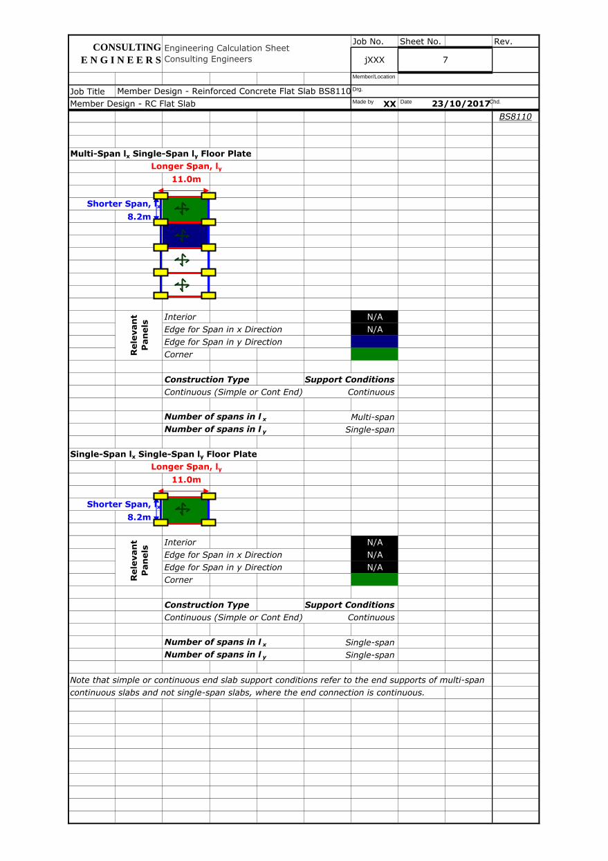
Multi-Span lx Single-Span ly Floor Plate
Longer Span, ly
11.0m
Shorter Span, lx
8.2m
Interior N/A
Edge for Span in x Direction N/A
Edge for Span in y Direction
Corner
Construction Type Support Conditions
Continuous (Simple or Cont End) Continuous
Number of spans in l x Multi-span
Number of spans in l y Single-span
Single-Span lx Single-Span ly Floor Plate
Longer Span, ly
11.0m
Shorter Span, lx
8.2m
Interior N/A
Edge for Span in x Direction N/A
Edge for Span in y Direction N/A
Corner
Construction Type Support Conditions
Continuous (Simple or Cont End) Continuous
Number of spans in l x Single-span
Number of spans in l y Single-span
Note that simple or continuous end slab support conditions refer to the end supports of multi-span
continuous slabs and not single-span slabs, where the end connection is continuous.
Rele
van
t
Pan
els
Rele
van
t
Pan
els
Engineering Calculation Sheet
Consulting Engineers jXXX 7
CONSULTING
E N G I N E E R S
23/10/2017
Member Design - Reinforced Concrete Flat Slab BS8110, ACI318 v2017.01.xlsm
Member Design - RC Flat Slab Made by Date Chd.
Drg.
Member/Location
Job No. Sheet No. Rev.
Job Title
XX
BS8110
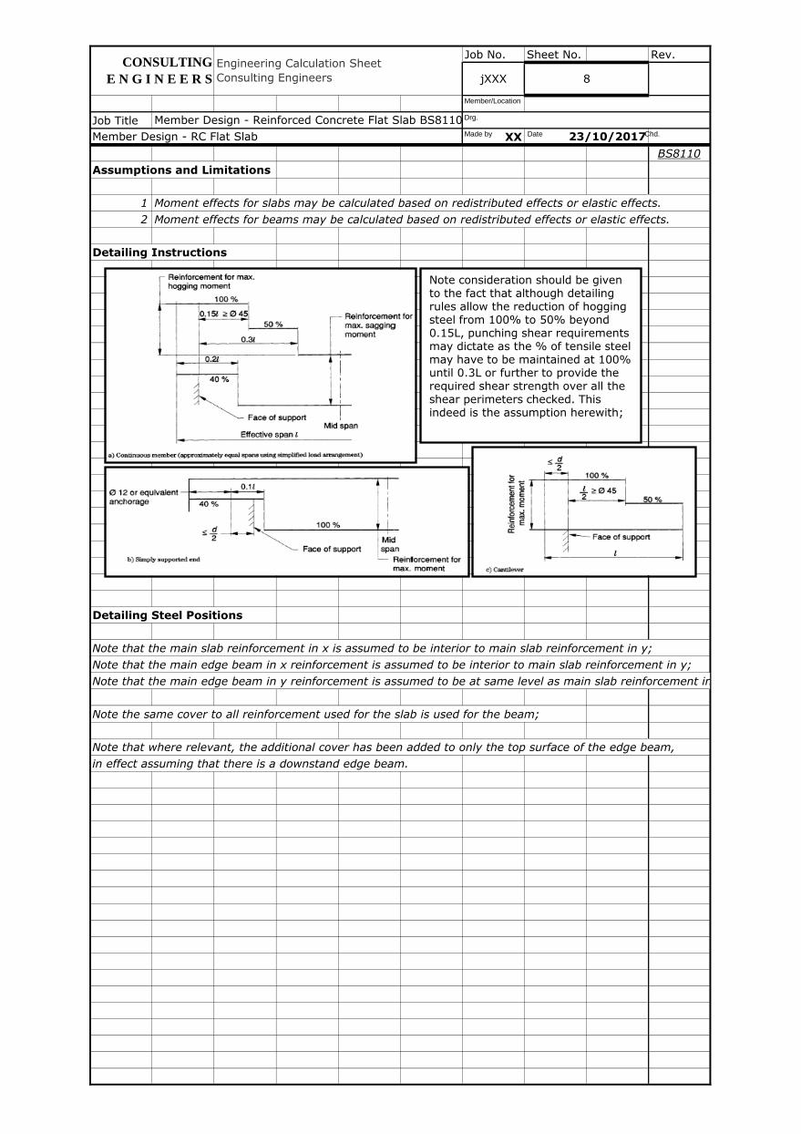
Assumptions and Limitations
1 Moment effects for slabs may be calculated based on redistributed effects or elastic effects.
2 Moment effects for beams may be calculated based on redistributed effects or elastic effects.
Detailing Instructions
Detailing Steel Positions
Note that the main slab reinforcement in x is assumed to be interior to main slab reinforcement in y;
Note that the main edge beam in x reinforcement is assumed to be interior to main slab reinforcement in y;
Note that the main edge beam in y reinforcement is assumed to be at same level as main slab reinforcement in y;
Note the same cover to all reinforcement used for the slab is used for the beam;
Note that where relevant, the additional cover has been added to only the top surface of the edge beam,
in effect assuming that there is a downstand edge beam.
8jXXX
CONSULTING
E N G I N E E R S
Engineering Calculation Sheet
Consulting Engineers
Member Design - Reinforced Concrete Flat Slab BS8110, ACI318 v2017.01.xlsm
Member Design - RC Flat Slab 23/10/2017Made by Date Chd.
Drg.
Member/Location
Note consideration should be given to the fact that although detailing rules allow the reduction of hogging steel from 100% to 50% beyond 0.15L, punching shear requirements may dictate as the % of tensile steel may have to be maintained at 100% until 0.3L or further to provide the required shear strength over all the shear perimeters checked. This indeed is the assumption herewith;
Job No. Sheet No. Rev.
Job Title
XX
BS8110
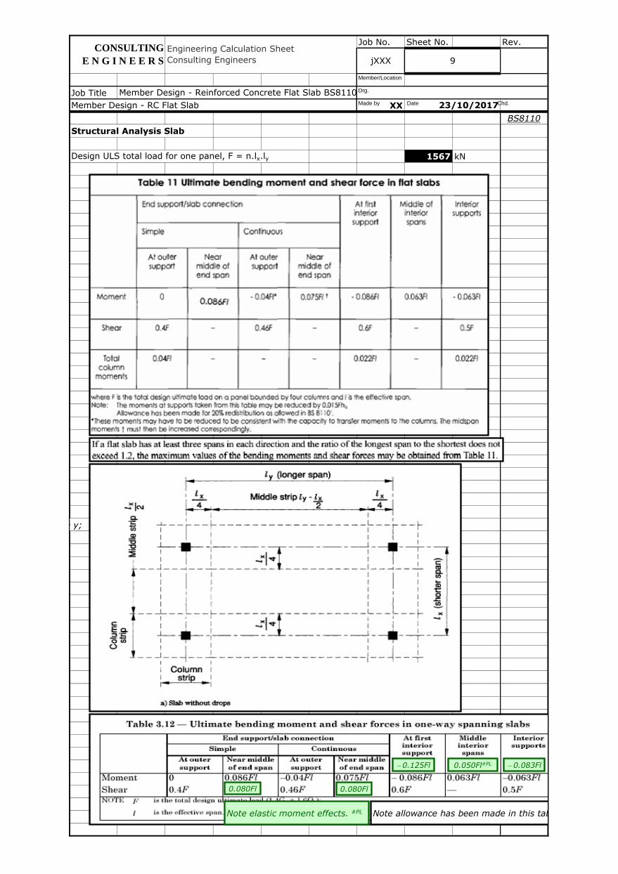
Structural Analysis Slab
Design ULS total load for one panel, F = n.lx.ly 1567 kN
Note that the main edge beam in y reinforcement is assumed to be at same level as main slab reinforcement in y;
CONSULTING
E N G I N E E R S
Member Design - Reinforced Concrete Flat Slab BS8110, ACI318 v2017.01.xlsm
jXXX 9
Engineering Calculation Sheet
Consulting Engineers
Member Design - RC Flat Slab 23/10/2017Made by Date Chd.
Drg.
Member/Location
Note allowance has been made in this tableNote elastic moment effects. #PL
0.080Fl 0.080Fl
- 0.125Fl - 0.083Fl 0.050Fl#PL
Job No. Sheet No. Rev.
Job Title
XX
BS8110
Shorter Span, lx
Width of column strip, w1,lx = IF (wdp<lx/3, lx/2, wdp) 2.800 m
Width of middle strip, w2,lx = ly - w1,lx 8.200 m
Sag moment for s/s case = 0.125F.lx (single span) 1606 kNm
Hog moment for s/s case = 803 kNm
0.0625F.lx (single span continuous - simple or continuous end)
Shear for s/s case = 0.5F (single span) 783 kN
Column moment for s/s case = 0.04Flx (single span) 514 kNm
Moment 0 1028 514 1028 1606 642 1066 kNm
Shear 627 N/A 721 N/A 940 N/A 783 kN
Col Mnt 514 N/A N/A N/A 283 N/A 283 kNm
Note that for edge panels, the shear force has been calculated for the less critical outer support
instead of the first interior support because the SDL will be more critical here due to the external cladding.
Note that l above refers to l x .
Sag moment, Msag,lx 642 kNm
Hog moment, Mhog,lx 1066 kNm
Shear, Vlx 783 kN
Column moment, Mcol,lx 283 kNm
Sag moment mid strip, Msag,lx,m=0.45w2,lx/(ly-lx/2).Msag,lx 343 kNm
Sag moment col strip, Msag,lx,c=[1-0.45w2,lx/(ly-lx/2)].Msag,lx 299 kNm
Hog moment mid strip, Mhog,lx,m=0.25w2,lx/(ly-lx/2).Mhog,lx 317 kNm
Hog moment col strip, Mhog,lx,c=[1-0.25w2,lx/(ly-lx/2)].Mhog,lx 749 kNm
Member Design - Reinforced Concrete Flat Slab BS8110, ACI318 v2017.01.xlsm
At outer
support
Middle of
interior
spans
Interior
supports
Interior
jXXX 10
Simple End Continuous End
Near
middle of
end span
At outer
support
Near
middle of
end span
At first
interior
support
Engineering Calculation Sheet
Consulting Engineers
CONSULTING
E N G I N E E R S
Member Design - RC Flat Slab 23/10/2017Made by Date Chd.
Drg.
Member/Location
table

Job No. Sheet No. Rev.
Job Title
XX
BS8110
Longer Span, ly
Width of column strip, w1,ly = IF (wdp<lx/3, lx/2, wdp) 2.800 m
Width of middle strip, w2,ly = lx - w1,ly 5.400 m
Sag moment for s/s case = 0.125F.ly (single span) 2154 kNm
Hog moment for s/s case = 1077 kNm
0.0625F.ly (single span continuous - simple or continuous end)
Shear for s/s case = 0.5F (single span) 783 kN
Column moment for s/s case = 0.04Fly (single span) 689 kNm
Moment 0 1379 689 1379 2154 862 1430 kNm
Shear 627 N/A 721 N/A 940 N/A 783 kN
Col Mnt 689 N/A N/A N/A 379 N/A 379 kNm
Note that for edge panels, the shear force has been calculated for the less critical outer support
instead of the first interior support because the SDL will be more critical here due to the external cladding.
Note that l above refers to l y .
Sag moment, Msag,ly 862 kNm
Hog moment, Mhog,ly 1430 kNm
Shear, Vly 783 kN
Column moment, Mcol,ly 379 kNm
Sag moment mid strip, Msag,ly,m=0.45w2,ly/(lx/2).Msag,ly 511 kNm
Sag moment col strip, Msag,ly,c=[1-0.45w2,ly/(lx/2)].Msag,ly 351 kNm
Hog moment mid strip, Mhog,ly,m=0.25w2,ly/(lx/2).Mhog,ly 471 kNm
Hog moment col strip, Mhog,ly,c=[1-0.25w2,ly/(lx/2)].Mhog,ly 959 kNm
Member Design - Reinforced Concrete Flat Slab BS8110, ACI318 v2017.01.xlsm
Middle of
interior
spans
At first
interior
support
Interior
Member Design - RC Flat Slab 23/10/2017
CONSULTING
E N G I N E E R S
Engineering Calculation Sheet
Consulting Engineers jXXX 11
Interior
supports
Simple End Continuous End
Near
middle of
end span
At outer
support
Near
middle of
end span
At outer
support
Made by Date Chd.
Drg.
Member/Location
Job No. Sheet No. Rev.
Job Title
XX
BS8110
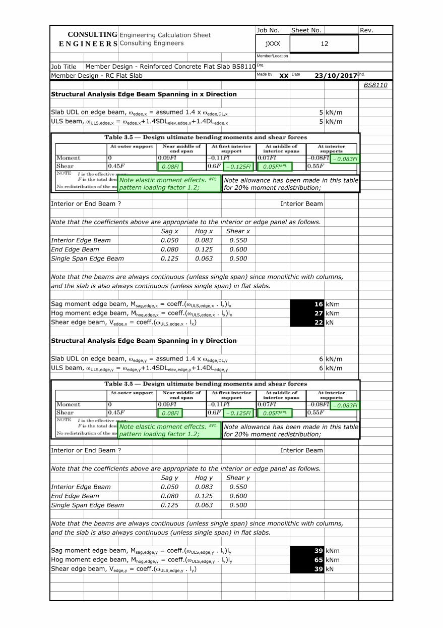
Structural Analysis Edge Beam Spanning in x Direction
Slab UDL on edge beam, wedge,x = assumed 1.4 x wedge,DL,x 5 kN/m
ULS beam, wULS,edge,x = wedge,x+1.4SDLelev,edge,x+1.4DLedge,x 5 kN/m
Interior or End Beam ? Interior Beam
Note that the coefficients above are appropriate to the interior or edge panel as follows.
Sag x Hog x Shear x
Interior Edge Beam 0.050 0.083 0.550
End Edge Beam 0.080 0.125 0.600
Single Span Edge Beam 0.125 0.063 0.500
Note that the beams are always continuous (unless single span) since monolithic with columns,
and the slab is also always continuous (unless single span) in flat slabs.
Sag moment edge beam, Msag,edge,x = coeff.(wULS,edge,x . lx)lx 16 kNm
Hog moment edge beam, Mhog,edge,x = coeff.(wULS,edge,x . lx)lx 27 kNm
Shear edge beam, Vedge,x = coeff.(wULS,edge,x . lx) 22 kN
Structural Analysis Edge Beam Spanning in y Direction
Slab UDL on edge beam, wedge,y = assumed 1.4 x wedge,DL,y 6 kN/m
ULS beam, wULS,edge,y = wedge,y+1.4SDLelev,edge,y+1.4DLedge,y 6 kN/m
Interior or End Beam ? Interior Beam
Note that the coefficients above are appropriate to the interior or edge panel as follows.
Sag y Hog y Shear y
Interior Edge Beam 0.050 0.083 0.550
End Edge Beam 0.080 0.125 0.600
Single Span Edge Beam 0.125 0.063 0.500
Note that the beams are always continuous (unless single span) since monolithic with columns,
and the slab is also always continuous (unless single span) in flat slabs.
Sag moment edge beam, Msag,edge,y = coeff.(wULS,edge,y . ly)ly 39 kNm
Hog moment edge beam, Mhog,edge,y = coeff.(wULS,edge,y . ly)ly 65 kNm
Shear edge beam, Vedge,y = coeff.(wULS,edge,y . ly) 39 kN
CONSULTING
E N G I N E E R S jXXX 12
Engineering Calculation Sheet
Consulting Engineers
Member Design - Reinforced Concrete Flat Slab BS8110, ACI318 v2017.01.xlsm
Member Design - RC Flat Slab 23/10/2017
Note allowance has been made in this table for 20% moment redistribution;
Note elastic moment effects. #PL pattern loading factor 1.2;
0.08Fl 0.05Fl#PL - 0.125Fl
- 0.083Fl
Made by Date Chd.
Drg.
Member/Location
Note allowance has been made in this table for 20% moment redistribution;
Note elastic moment effects. #PL pattern loading factor 1.2;
0.08Fl 0.05Fl#PL - 0.125Fl
- 0.083Fl
Job No. Sheet No. Rev.
Job Title
XX
BS8110
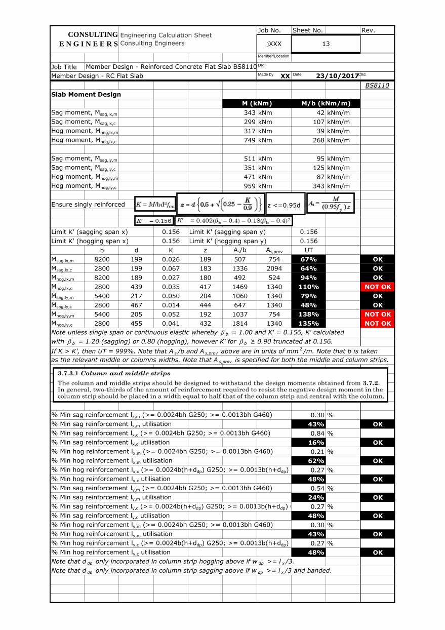
Slab Moment Design
Sag moment, Msag,lx,m 343 kNm 42 kNm/m
Sag moment, Msag,lx,c 299 kNm 107 kNm/m
Hog moment, Mhog,lx,m 317 kNm 39 kNm/m
Hog moment, Mhog,lx,c 749 kNm 268 kNm/m
Sag moment, Msag,ly,m 511 kNm 95 kNm/m
Sag moment, Msag,ly,c 351 kNm 125 kNm/m
Hog moment, Mhog,ly,m 471 kNm 87 kNm/m
Hog moment, Mhog,ly,c 959 kNm 343 kNm/m
Ensure singly reinforced
Limit K' (sagging span x) 0.156 Limit K' (sagging span y) 0.156
Limit K' (hogging span x) 0.156 Limit K' (hogging span y) 0.156
b d K z As/b As,prov UT
Msag,lx,m 8200 199 0.026 189 507 754 67% OK
Msag,lx,c 2800 199 0.067 183 1336 2094 64% OK
Mhog,lx,m 8200 189 0.027 180 492 524 94% OK
Mhog,lx,c 2800 439 0.035 417 1469 1340 110% NOT OK
Msag,ly,m 5400 217 0.050 204 1060 1340 79% OK
Msag,ly,c 2800 467 0.014 444 647 1340 48% OK
Mhog,ly,m 5400 205 0.052 192 1037 754 138% NOT OK
Mhog,ly,c 2800 455 0.041 432 1814 1340 135% NOT OK
Note unless single span or continuous elastic whereby b b = 1.00 and K' = 0.156, K' calculated
with b b = 1.20 (sagging) or 0.80 (hogging), however K' for b b ≥ 0.90 truncated at 0.156.
If K > K', then UT = 999%. Note that A s /b and A s,prov above are in units of mm2/m. Note that b is taken
as the relevant middle or columns widths. Note that A s,prov is specified for both the middle and column strips.
% Min sag reinforcement lx,m (>= 0.0024bh G250; >= 0.0013bh G460) 0.30 %
% Min sag reinforcement lx,m utilisation 43% OK
% Min sag reinforcement lx,c (>= 0.0024bh G250; >= 0.0013bh G460) 0.84 %
% Min sag reinforcement lx,c utilisation 16% OK
% Min hog reinforcement lx,m (>= 0.0024bh G250; >= 0.0013bh G460) 0.21 %
% Min hog reinforcement lx,m utilisation 62% OK
% Min hog reinforcement lx,c (>= 0.0024b(h+ddp) G250; >= 0.0013b(h+ddp) G460)0.27 %
% Min hog reinforcement lx,c utilisation 48% OK
% Min sag reinforcement ly,m (>= 0.0024bh G250; >= 0.0013bh G460) 0.54 %
% Min sag reinforcement ly,m utilisation 24% OK
% Min sag reinforcement ly,c (>= 0.0024b(h+ddp) G250; >= 0.0013b(h+ddp) G460) 0.27 %
% Min sag reinforcement ly,c utilisation 48% OK
% Min hog reinforcement ly,m (>= 0.0024bh G250; >= 0.0013bh G460) 0.30 %
% Min hog reinforcement ly,m utilisation 43% OK
% Min hog reinforcement ly,c (>= 0.0024b(h+ddp) G250; >= 0.0013b(h+ddp) G460)0.27 %
% Min hog reinforcement ly,c utilisation 48% OK
Note that d dp only incorporated in column strip hogging above if w dp >= l x /3.
Note that d dp only incorporated in column strip sagging above if w dp >= l x /3 and banded.
23/10/2017
M (kNm) M/b (kNm/m)
CONSULTING
E N G I N E E R S
Engineering Calculation Sheet
Consulting Engineers 13
Member Design - RC Flat Slab
Member Design - Reinforced Concrete Flat Slab BS8110, ACI318 v2017.01.xlsm
jXXX
z <=0.95d
Made by Date Chd.
Drg.
Member/Location
Job No. Sheet No. Rev.
Job Title
XX
BS8110
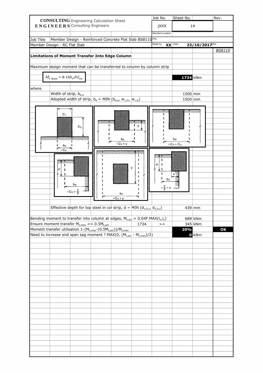
Limitations of Moment Transfer Into Edge Column
Maximum design moment that can be transferred to column by column strip
1734 kNm
where
Width of strip, be,a 1500 mm
Adopted width of strip, be = MIN (be,a, w1,lx, w1,ly) 1500 mm
Effective depth for top steel in col strip, d = MIN (dx,h,c, dy,h,c) 439 mm
Bending moment to transfer into column at edges, Mt,act = 0.04F.MAX(lx,ly) 689 kNm
Ensure moment transfer Mt,max >= 0.5Mt,act 1734 >= 345 kNm
Moment transfer utilisation 1-(Mt,max-(0.5Mt,act))/Mt,max 20% OK
Need to increase end span sag moment ? MAX(0, (Mt,act - Mt,max)/2) 0 kNm
Member Design - Reinforced Concrete Flat Slab BS8110, ACI318 v2017.01.xlsm
23/10/2017Member Design - RC Flat Slab
jXXX 14
CONSULTING
E N G I N E E R S
Engineering Calculation Sheet
Consulting Engineers
Made by Date Chd.
Drg.
Member/Location
Job No. Sheet No. Rev.
Job Title
XX
BS8110
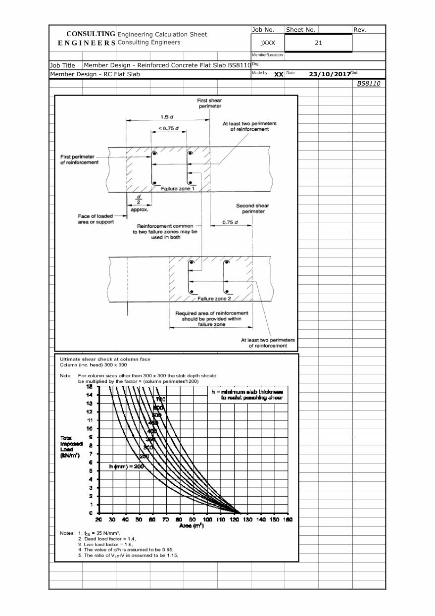
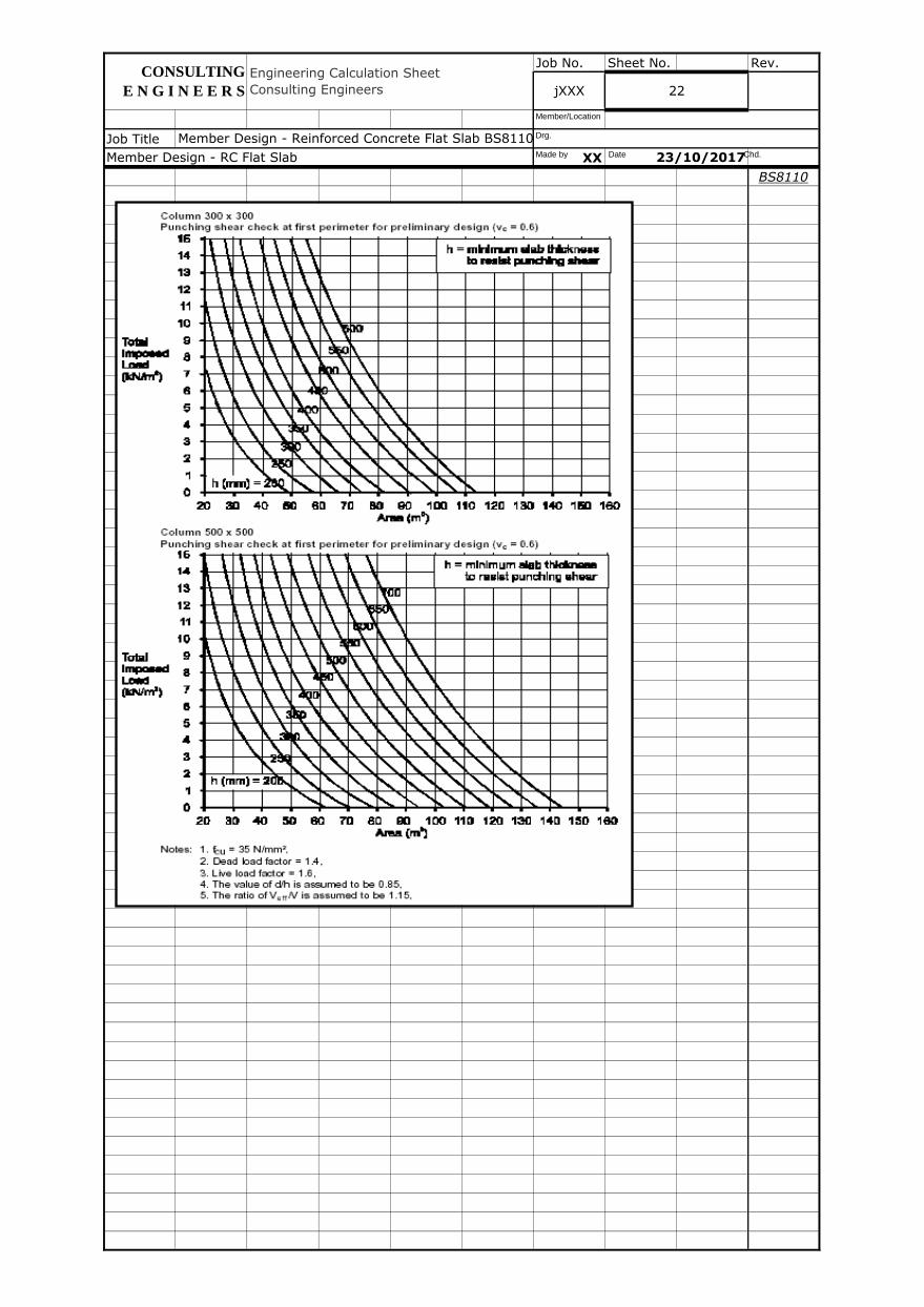
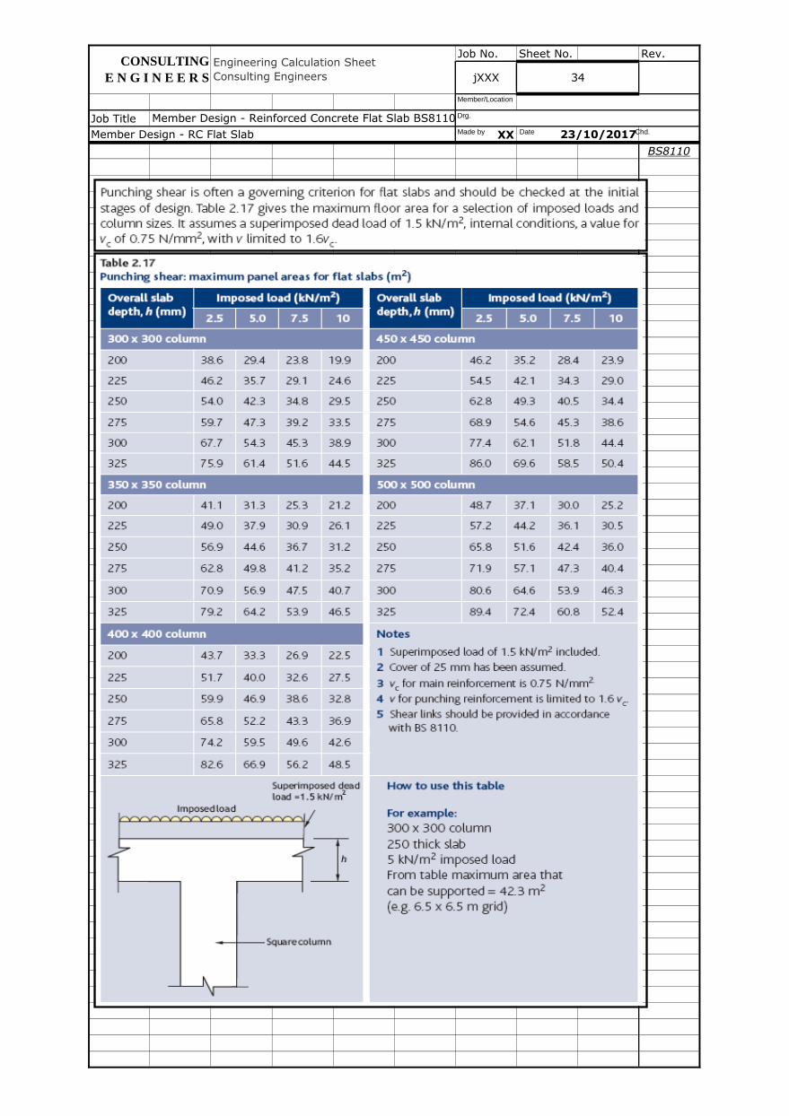
Punching Shear (BS8110)
ULS design punching shear into column, Vt 1567 kN
Note V t = F (internal), F/2+SDL elev,x/y .l x/y (edge), F/4+(SDL elev,x .l x +SDL elev,y .l y )/2 (corner).
Area of column section, Ac1 = lh,b.lh,h (rectangular) or plh,D2/4 (circular) 900000 mm
2
Average effective depth of both rebar layers, d = (dx,h,c + dy,h,c)/2 - {0, ddp} 447 mm
Note conservatively that d dp should not be incorporated above when incorporated within d x,h,c and
d y,h,c to cater for the reduced effective depth at shear perimeters beyond the slab drop widths.
Area of tensile steel reinforcement provided, As,prov,x,h,c 1340 mm2/m
Area of tensile steel reinforcement provided, As,prov,y,h,c 1340 mm2/m
Average area of tensile steel reinforcement provided, As,prov,h,c 1340 mm2/m
rw = 100As,prov,h,c/bd 0.30 %
nc = (0.79/1.25)(rwfcu/25)1/3
(400/d)1/4
; rw<3; fcu<40; (400/d)1/4
>0.67 0.48 N/mm2
Column Face Perimeter
Shear force at column face, V1 = Vt - n.Ac1 1551 kN
Effective shear force, Veff,1 = (1.15 internal, 1.40 edge column) . V1 1784 kN
Column face perimeter, u1 4200 mm
Internal column: 2.(l h,b +l h,h ) 4200 p .l h,D N/A mm
Edge column: 2l h,b +l h,h or 2l h,h +l h,b 3600 3/4( p .l h,D ) N/A mm
Corner column: (l h,b +l h,h ) 2100 p .l h,D /2 N/A mm
Shear stress at column face perimeter, n1 = Veff,1 / u1d (< 0.8fcu0.5
& 5N/mm2) 0.95 N/mm
2
Ultimate shear stress utilisation 19% OK
jXXX 15
Member Design - RC Flat Slab 23/10/2017
Member Design - Reinforced Concrete Flat Slab BS8110, ACI318 v2017.01.xlsm
Rectangular Circular
CONSULTING
E N G I N E E R S
Engineering Calculation Sheet
Consulting Engineers
Made by Date Chd.
Drg.
Member/Location
Job No. Sheet No. Rev.
Job Title
XX
BS8110
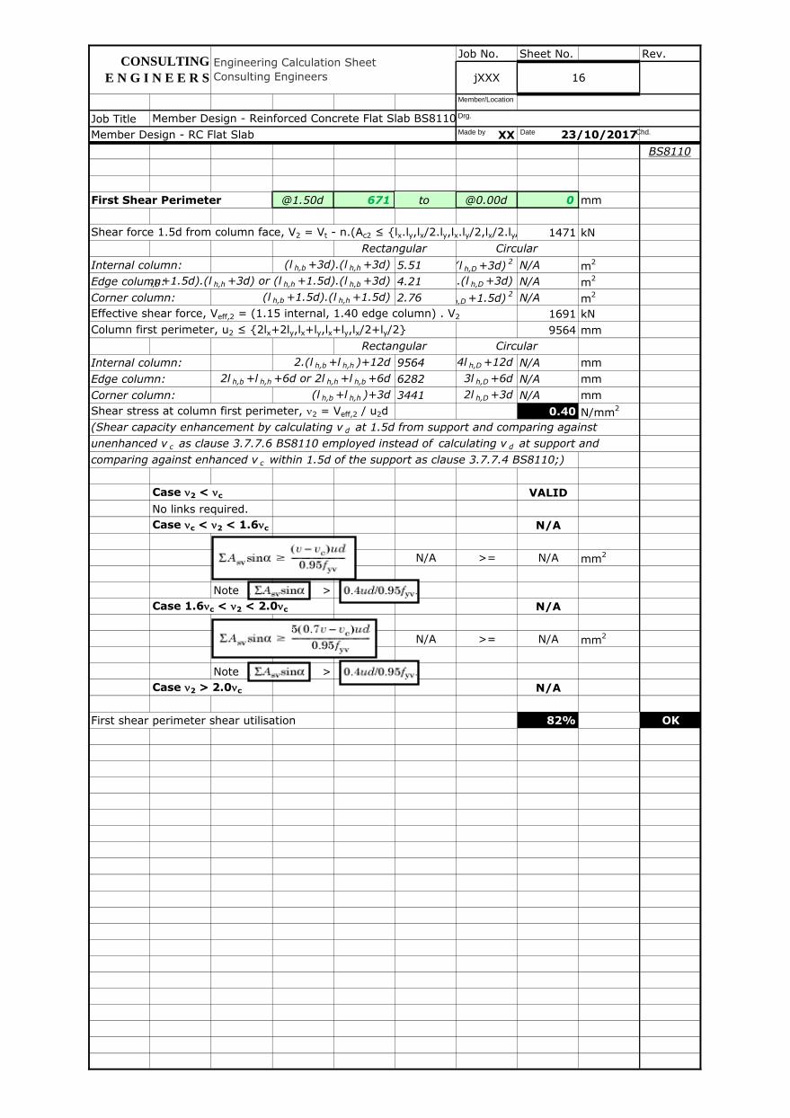
First Shear Perimeter @1.50d 671 1 @0.00d 0 mm
Shear force 1.5d from column face, V2 = Vt - n.(Ac2 ≤ {lx.ly,lx/2.ly,lx.ly/2,lx/2.ly/2}) 1471 kN
Internal column: (l h,b +3d).(l h,h +3d) 5.51 (l h,D +3d)2 N/A m
2
Edge column:(l h,b +1.5d).(l h,h +3d) or (l h,h +1.5d).(l h,b +3d) 4.21(l h,D +1.5d).(l h,D +3d) N/A m2
Corner column: (l h,b +1.5d).(l h,h +1.5d) 2.76 (l h,D +1.5d)2 N/A m
2
Effective shear force, Veff,2 = (1.15 internal, 1.40 edge column) . V2 1691 kN
Column first perimeter, u2 ≤ {2lx+2ly,lx+ly,lx+ly,lx/2+ly/2} 9564 mm
Internal column: 2.(l h,b +l h,h )+12d 9564 4l h,D +12d N/A mm
Edge column: 2l h,b +l h,h +6d or 2l h,h +l h,b +6d 6282 3l h,D +6d N/A mm
Corner column: (l h,b +l h,h )+3d 3441 2l h,D +3d N/A mm
Shear stress at column first perimeter, n2 = Veff,2 / u2d 0.40 N/mm2
(Shear capacity enhancement by calculating v d at 1.5d from support and comparing against
unenhanced v c as clause 3.7.7.6 BS8110 employed instead of calculating v d at support and
comparing against enhanced v c within 1.5d of the support as clause 3.7.7.4 BS8110;)
Case n2 < nc VALID
No links required.
Case nc < n2 < 1.6nc N/A
N/A >= N/A mm2
Note >
Case 1.6nc < n2 < 2.0nc N/A
N/A >= N/A mm2
Note >
Case n2 > 2.0nc N/A
First shear perimeter shear utilisation 82% OK
Member Design - Reinforced Concrete Flat Slab BS8110, ACI318 v2017.01.xlsm
16
Rectangular Circular
Rectangular Circular
Member Design - RC Flat Slab
Engineering Calculation Sheet
Consulting Engineers
CONSULTING
E N G I N E E R S jXXX
23/10/2017Made by Date Chd.
Drg.
Member/Location
to
Job No. Sheet No. Rev.
Job Title
XX
BS8110
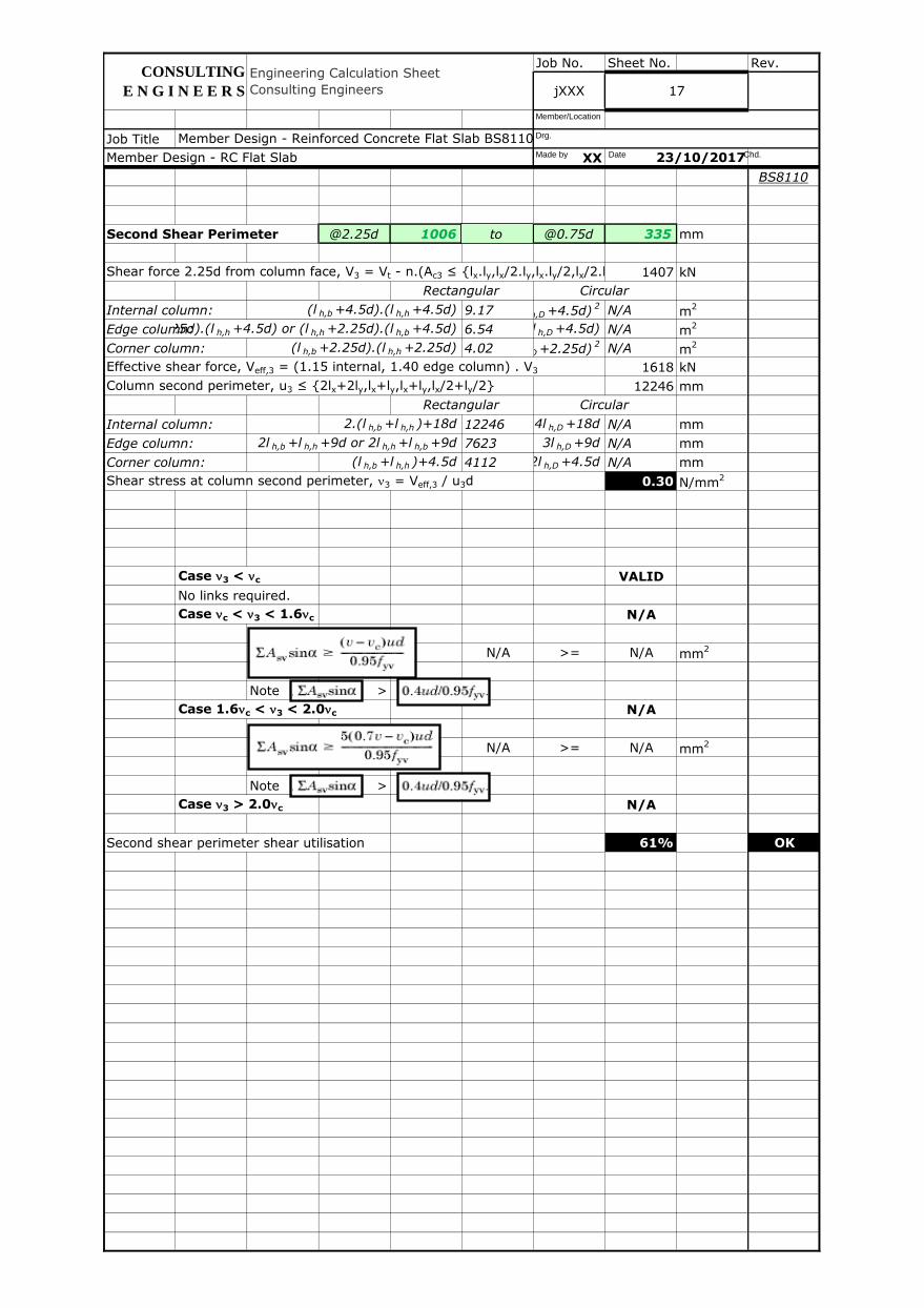
Second Shear Perimeter @2.25d 1006 2 @0.75d 335 mm
Shear force 2.25d from column face, V3 = Vt - n.(Ac3 ≤ {lx.ly,lx/2.ly,lx.ly/2,lx/2.ly/2}) 1407 kN
Internal column: (l h,b +4.5d).(l h,h +4.5d) 9.17 (l h,D +4.5d)2 N/A m
2
Edge column:(l h,b +2.25d).(l h,h +4.5d) or (l h,h +2.25d).(l h,b +4.5d) 6.54(l h,D +2.25d).(l h,D +4.5d) N/A m2
Corner column: (l h,b +2.25d).(l h,h +2.25d) 4.02 (l h,D +2.25d)2 N/A m
2
Effective shear force, Veff,3 = (1.15 internal, 1.40 edge column) . V3 1618 kN
Column second perimeter, u3 ≤ {2lx+2ly,lx+ly,lx+ly,lx/2+ly/2} 12246 mm
Internal column: 2.(l h,b +l h,h )+18d 12246 4l h,D +18d N/A mm
Edge column: 2l h,b +l h,h +9d or 2l h,h +l h,b +9d 7623 3l h,D +9d N/A mm
Corner column: (l h,b +l h,h )+4.5d 4112 2l h,D +4.5d N/A mm
Shear stress at column second perimeter, n3 = Veff,3 / u3d 0.30 N/mm2
Case n3 < nc VALID
No links required.
Case nc < n3 < 1.6nc N/A
N/A >= N/A mm2
Note >
Case 1.6nc < n3 < 2.0nc N/A
N/A >= N/A mm2
Note >
Case n3 > 2.0nc N/A
Second shear perimeter shear utilisation 61% OK
Rectangular Circular
Engineering Calculation Sheet
Consulting Engineers
Member Design - Reinforced Concrete Flat Slab BS8110, ACI318 v2017.01.xlsm
17jXXX
CONSULTING
E N G I N E E R S
Member Design - RC Flat Slab
Rectangular Circular
23/10/2017Made by Date Chd.
Drg.
Member/Location
to

Job No. Sheet No. Rev.
Job Title
XX
BS8110
Third Shear Perimeter @3.00d 1341 3 @1.50d 671 mm
Shear force 3.0d from column face, V4 = Vt - n.(Ac4 ≤ {lx.ly,lx/2.ly,lx.ly/2,lx/2.ly/2}) 1328 kN
Internal column: (l h,b +6d).(l h,h +6d) 13.73 (l h,D +6d)2 N/A m
2
Edge column:(l h,b +3d).(l h,h +6d) or (l h,h +3d).(l h,b +6d) 9.32(l h,D +3d).(l h,D +6d) N/A m2
Corner column: (l h,b +3d).(l h,h +3d) 5.51 (l h,D +3d)2 N/A m
2
Effective shear force, Veff,4 = (1.15 internal, 1.40 edge column) . V4 1527 kN
Column third perimeter, u4 ≤ {2lx+2ly,lx+ly,lx+ly,lx/2+ly/2} 14928 mm
Internal column: 2.(l h,b +l h,h )+24d 14928 4l h,D +24d N/A mm
Edge column: 2l h,b +l h,h +12d or 2l h,h +l h,b +12d 8964 3l h,D +12d N/A mm
Corner column: (l h,b +l h,h )+6d 4782 2l h,D +6d N/A mm
Shear stress at column third perimeter, n4 = Veff,4 / u4d 0.23 N/mm2
Case n4 < nc VALID
No links required.
Case nc < n4 < 1.6nc N/A
N/A >= N/A mm2
Note >
Case 1.6nc < n4 < 2.0nc N/A
N/A >= N/A mm2
Note >
Case n4 > 2.0nc N/A
Third shear perimeter shear utilisation 48% OK
jXXX
Engineering Calculation Sheet
Consulting Engineers
CONSULTING
E N G I N E E R S 18
Circular
Rectangular Circular
Rectangular
23/10/2017
Member Design - Reinforced Concrete Flat Slab BS8110, ACI318 v2017.01.xlsm
Member Design - RC Flat Slab Made by Date Chd.
Drg.
Member/Location
to
Job No. Sheet No. Rev.
Job Title
XX
BS8110
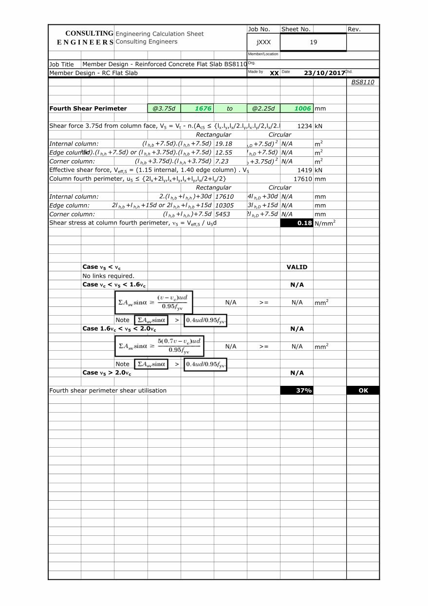
Fourth Shear Perimeter @3.75d 1676 4 @2.25d 1006 mm
Shear force 3.75d from column face, V5 = Vt - n.(Ac5 ≤ {lx.ly,lx/2.ly,lx.ly/2,lx/2.ly/2}) 1234 kN
Internal column: (l h,b +7.5d).(l h,h +7.5d) 19.18 (l h,D +7.5d)2 N/A m
2
Edge column:(l h,b +3.75d).(l h,h +7.5d) or (l h,h +3.75d).(l h,b +7.5d) 12.55(l h,D +3.75d).(l h,D +7.5d) N/A m2
Corner column: (l h,b +3.75d).(l h,h +3.75d) 7.23 (l h,D +3.75d)2 N/A m
2
Effective shear force, Veff,5 = (1.15 internal, 1.40 edge column) . V5 1419 kN
Column fourth perimeter, u5 ≤ {2lx+2ly,lx+ly,lx+ly,lx/2+ly/2} 17610 mm
Internal column: 2.(l h,b +l h,h )+30d 17610 4l h,D +30d N/A mm
Edge column: 2l h,b +l h,h +15d or 2l h,h +l h,b +15d 10305 3l h,D +15d N/A mm
Corner column: (l h,b +l h,h )+7.5d 5453 2l h,D +7.5d N/A mm
Shear stress at column fourth perimeter, n5 = Veff,5 / u5d 0.18 N/mm2
Case n5 < nc VALID
No links required.
Case nc < n5 < 1.6nc N/A
N/A >= N/A mm2
Note >
Case 1.6nc < n5 < 2.0nc N/A
N/A >= N/A mm2
Note >
Case n5 > 2.0nc N/A
Fourth shear perimeter shear utilisation 37% OK
19
CONSULTING
E N G I N E E R S jXXX
Engineering Calculation Sheet
Consulting Engineers
Rectangular Circular
Rectangular Circular
Member Design - RC Flat Slab 23/10/2017
Member Design - Reinforced Concrete Flat Slab BS8110, ACI318 v2017.01.xlsmMade by Date Chd.
Drg.
Member/Location
to
Job No. Sheet No. Rev.
Job Title
XX
BS8110
Member Design - Reinforced Concrete Flat Slab BS8110, ACI318 v2017.01.xlsm
Member Design - RC Flat Slab
CONSULTING
E N G I N E E R S
Engineering Calculation Sheet
Consulting Engineers jXXX 20
23/10/2017Made by Date Chd.
Drg.
Member/Location
Job No. Sheet No. Rev.
Job Title
XX
BS8110
CONSULTING
E N G I N E E R S
Member Design - RC Flat Slab
Member Design - Reinforced Concrete Flat Slab BS8110, ACI318 v2017.01.xlsm
23/10/2017
Engineering Calculation Sheet
Consulting Engineers 21jXXX
Made by Date Chd.
Drg.
Member/Location
Job No. Sheet No. Rev.
Job Title
XX
BS8110
Member Design - RC Flat Slab 23/10/2017
Engineering Calculation Sheet
Consulting Engineers
CONSULTING
E N G I N E E R S jXXX 22
Member Design - Reinforced Concrete Flat Slab BS8110, ACI318 v2017.01.xlsmMade by Date Chd.
Drg.
Member/Location
Job No. Sheet No. Rev.
Job Title
XX
ACI318
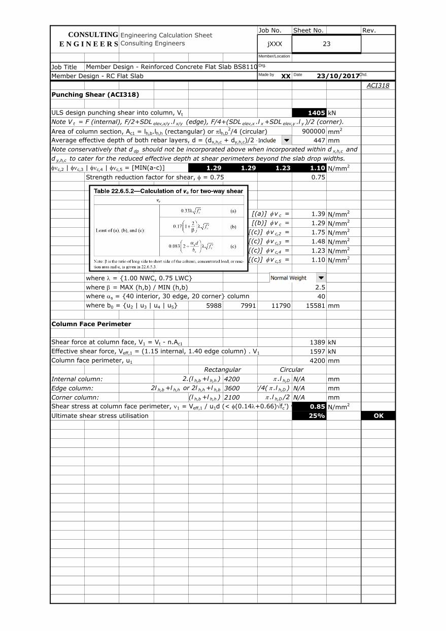
Punching Shear (ACI318)
ULS design punching shear into column, Vt 1405 kN
Note V t = F (internal), F/2+SDL elev,x/y .l x/y (edge), F/4+(SDL elev,x .l x +SDL elev,y .l y )/2 (corner).
Area of column section, Ac1 = lh,b.lh,h (rectangular) or plh,D2/4 (circular) 900000 mm
2
Average effective depth of both rebar layers, d = (dx,h,c + dy,h,c)/2 - {0, ddp} 447 mm
Note conservatively that d dp should not be incorporated above when incorporated within d x,h,c and
d y,h,c to cater for the reduced effective depth at shear perimeters beyond the slab drop widths.
fnc,2 | fnc,3 | fnc,4 | fnc,5 = [MIN(a-c)] 1.29 1.29 1.23 1.10 N/mm2
Strength reduction factor for shear, f = 0.75 0.75
[(a)] f v c = 1.39 N/mm2
[(b)] f v c = 1.29 N/mm2
[(c)] f v c,2 = 1.75 N/mm2
[(c)] f v c,3 = 1.48 N/mm2
[(c)] f v c,4 = 1.23 N/mm2
[(c)] f v c,5 = 1.10 N/mm2
where l = {1.00 NWC, 0.75 LWC}
where b = MAX (h,b) / MIN (h,b) 2.5
where as = {40 interior, 30 edge, 20 corner} column 40
where b0 = {u2 | u3 | u4 | u5} 5988 7991 11790 15581 mm
Column Face Perimeter
Shear force at column face, V1 = Vt - n.Ac1 1389 kN
Effective shear force, Veff,1 = (1.15 internal, 1.40 edge column) . V1 1597 kN
Column face perimeter, u1 4200 mm
Internal column: 2.(l h,b +l h,h ) 4200 p .l h,D N/A mm
Edge column: 2l h,b +l h,h or 2l h,h +l h,b 3600 3/4( p .l h,D ) N/A mm
Corner column: (l h,b +l h,h ) 2100 p .l h,D /2 N/A mm
Shear stress at column face perimeter, n1 = Veff,1 / u1d (< f(0.14l+0.66)fc') where f=0.75 and l = {1.00 NWC, 0.75 LWC}0.85 N/mm2
Ultimate shear stress utilisation 25% OK
Rectangular Circular
Member Design - RC Flat Slab 23/10/2017
CONSULTING
E N G I N E E R S
Engineering Calculation Sheet
Consulting Engineers jXXX 23
Member Design - Reinforced Concrete Flat Slab BS8110, ACI318 v2017.01.xlsmMade by Date Chd.
Drg.
Member/Location
Job No. Sheet No. Rev.
Job Title
XX
ACI318
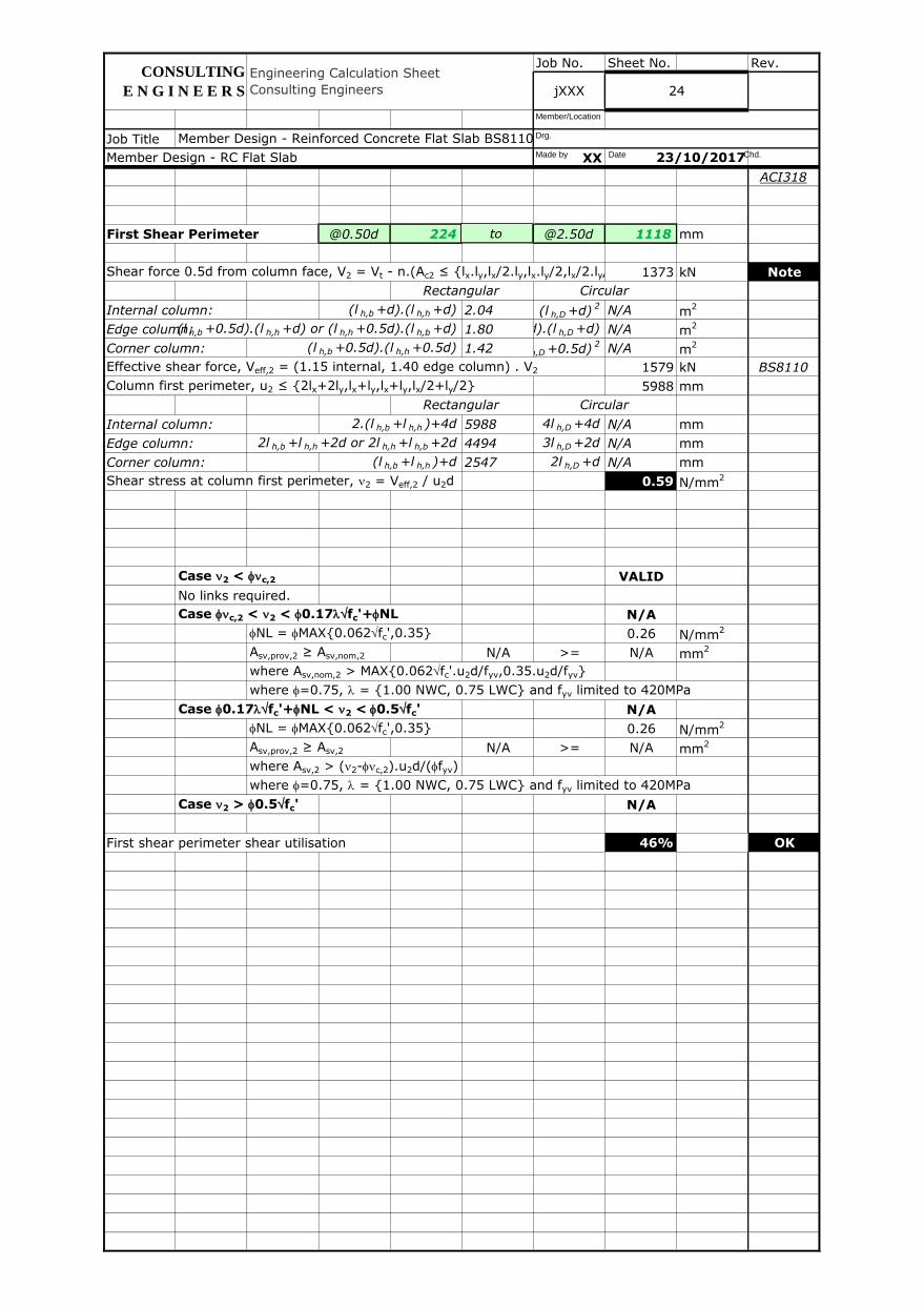
First Shear Perimeter @0.50d 224 1 @2.50d 1118 mm
Shear force 0.5d from column face, V2 = Vt - n.(Ac2 ≤ {lx.ly,lx/2.ly,lx.ly/2,lx/2.ly/2}) 1373 kN Note
Internal column: (l h,b +d).(l h,h +d) 2.04 (l h,D +d)2 N/A m
2
Edge column:(l h,b +0.5d).(l h,h +d) or (l h,h +0.5d).(l h,b +d) 1.80(l h,D +0.5d).(l h,D +d) N/A m2
Corner column: (l h,b +0.5d).(l h,h +0.5d) 1.42 (l h,D +0.5d)2 N/A m
2
Effective shear force, Veff,2 = (1.15 internal, 1.40 edge column) . V2 1579 kN BS8110
Column first perimeter, u2 ≤ {2lx+2ly,lx+ly,lx+ly,lx/2+ly/2} 5988 mm
Internal column: 2.(l h,b +l h,h )+4d 5988 4l h,D +4d N/A mm
Edge column: 2l h,b +l h,h +2d or 2l h,h +l h,b +2d 4494 3l h,D +2d N/A mm
Corner column: (l h,b +l h,h )+d 2547 2l h,D +d N/A mm
Shear stress at column first perimeter, n2 = Veff,2 / u2d 0.59 N/mm2
Case n2 < fnc,2 VALID
No links required.
Case fnc,2 < n2 < f0.17lfc'+fNL N/A
fNL = fMAX{0.062fc',0.35} 0.26 N/mm2
Asv,prov,2 ≥ Asv,nom,2 N/A >= N/A mm2
where Asv,nom,2 > MAX{0.062fc'.u2d/fyv,0.35.u2d/fyv}
where f=0.75, l = {1.00 NWC, 0.75 LWC} and fyv limited to 420MPa
Case f0.17lfc'+fNL < n2 < f0.5fc' N/A
fNL = fMAX{0.062fc',0.35} 0.26 N/mm2
Asv,prov,2 ≥ Asv,2 N/A >= N/A mm2
where Asv,2 > (n2-fnc,2).u2d/(ffyv)
where f=0.75, l = {1.00 NWC, 0.75 LWC} and fyv limited to 420MPa
Case n2 > f0.5fc' N/A
First shear perimeter shear utilisation 46% OK
Circular
Rectangular Circular
Rectangular
Member Design - Reinforced Concrete Flat Slab BS8110, ACI318 v2017.01.xlsm
Member Design - RC Flat Slab 23/10/2017
CONSULTING
E N G I N E E R S
Engineering Calculation Sheet
Consulting Engineers jXXX 24
Made by Date Chd.
Drg.
Member/Location
to

Job No. Sheet No. Rev.
Job Title
XX
ACI318
Second Shear Perimeter @1.50d 671 2 @3.50d 1565 mm
Shear force 1.5d from column face, V3 = Vt - n.(Ac3 ≤ {lx.ly,lx/2.ly,lx.ly/2,lx/2.ly/2}) 1346 kN Note
Internal column: (l h,b +2.12d).(l h,h +2.12d) 3.79 (l h,D +2.12d)2 N/A m
2
Edge column:(l h,b +1.06d).(l h,h +2.12d) or (l h,h +1.06d).(l h,b +2.12d) 3.05(l h,D +1.06d).(l h,D +2.12d) N/A m2
Corner column: (l h,b +1.06d).(l h,h +1.06d) 2.12 (l h,D +1.06d)2 N/A m
2
Effective shear force, Veff,3 = (1.15 internal, 1.40 edge column) . V3 1547 kN BS8110
Column second perimeter, u3 ≤ {2lx+2ly,lx+ly,lx+ly,lx/2+ly/2} 7991 mm
Internal column: 2.(l h,b +l h,h )+8.48d 7991 4l h,D +8.48d N/A mm
Edge column: 2l h,b +l h,h +4.24d or 2l h,h +l h,b +4.24d 5495 3l h,D +4.24d N/A mm
Corner column: (l h,b +l h,h )+2.12d 3048 2l h,D +2.12d N/A mm
Shear stress at column second perimeter, n3 = Veff,3 / u3d 0.43 N/mm2
Case n3 < fnc,3 VALID
No links required.
Case fnc,3 < n3 < f0.17lfc'+fNL N/A
fNL = fMAX{0.062fc',0.35} 0.26 N/mm2
Asv,prov,3 ≥ Asv,nom,3 N/A >= N/A mm2
where Asv,nom,3 > MAX{0.062fc'.u3d/fyv,0.35.u3d/fyv}
where f=0.75, l = {1.00 NWC, 0.75 LWC} and fyv limited to 420MPa
Case f0.17lfc'+fNL < n3 < f0.5fc' N/A
fNL = fMAX{0.062fc',0.35} 0.26 N/mm2
Asv,prov,3 ≥ Asv,3 N/A >= N/A mm2
where Asv,3 > (n3-fnc,3).u3d/(ffyv)
where f=0.75, l = {1.00 NWC, 0.75 LWC} and fyv limited to 420MPa
Case n3 > f0.5fc' N/A
Second shear perimeter shear utilisation 34% OK
Rectangular Circular
Engineering Calculation Sheet
Consulting Engineers jXXX 25
Rectangular Circular
Member Design - RC Flat Slab 23/10/2017
Member Design - Reinforced Concrete Flat Slab BS8110, ACI318 v2017.01.xlsm
CONSULTING
E N G I N E E R S
Made by Date Chd.
Drg.
Member/Location
to

Job No. Sheet No. Rev.
Job Title
XX
ACI318
Third Shear Perimeter @3.00d 1341 3 @5.00d 2235 mm
Shear force 3.0d from column face, V4 = Vt - n.(Ac4 ≤ {lx.ly,lx/2.ly,lx.ly/2,lx/2.ly/2}) 1273 kN Note
Internal column: (l h,b +4.24d).(l h,h +4.24d) 8.47 (l h,D +4.24d)2 N/A m
2
Edge column:(l h,b +2.12d).(l h,h +4.24d) or (l h,h +2.12d).(l h,b +4.24d) 6.11(l h,D +2.12d).(l h,D +4.24d) N/A m2
Corner column: (l h,b +2.12d).(l h,h +2.12d) 3.79 (l h,D +2.12d)2 N/A m
2
Effective shear force, Veff,4 = (1.15 internal, 1.40 edge column) . V4 1464 kN BS8110
Column third perimeter, u4 ≤ {2lx+2ly,lx+ly,lx+ly,lx/2+ly/2} 11790 mm
Internal column: 2.(l h,b +l h,h )+16.97d 11790 4l h,D +16.97d N/A mm
Edge column: 2l h,b +l h,h +8.49d or 2l h,h +l h,b +8.49d 7395 3l h,D +8.49d N/A mm
Corner column: (l h,b +l h,h )+4.24d 3995 2l h,D +4.24d N/A mm
Shear stress at column third perimeter, n4 = Veff,4 / u4d 0.28 N/mm2
Case n4 < fnc,4 VALID
No links required.
Case fnc,4 < n4 < f0.17lfc'+fNL N/A
fNL = fMAX{0.062fc',0.35} 0.26 N/mm2
Asv,prov,4 ≥ Asv,nom,4 N/A >= N/A mm2
where Asv,nom,4 > MAX{0.062fc'.u4d/fyv,0.35.u4d/fyv}
where f=0.75, l = {1.00 NWC, 0.75 LWC} and fyv limited to 420MPa
Case f0.17lfc'+fNL < n4 < f0.5fc' N/A
fNL = fMAX{0.062fc',0.35} 0.26 N/mm2
Asv,prov,4 ≥ Asv,4 N/A >= N/A mm2
where Asv,4 > (n4-fnc,4).u4d/(ffyv)
where f=0.75, l = {1.00 NWC, 0.75 LWC} and fyv limited to 420MPa
Case n4 > f0.5fc' N/A
Third shear perimeter shear utilisation 23% OK
Rectangular Circular
Rectangular Circular
Member Design - RC Flat Slab 23/10/2017
Engineering Calculation Sheet
Consulting Engineers jXXX 26
Member Design - Reinforced Concrete Flat Slab BS8110, ACI318 v2017.01.xlsm
CONSULTING
E N G I N E E R S
Made by Date Chd.
Drg.
Member/Location
to
Job No. Sheet No. Rev.
Job Title
XX
ACI318
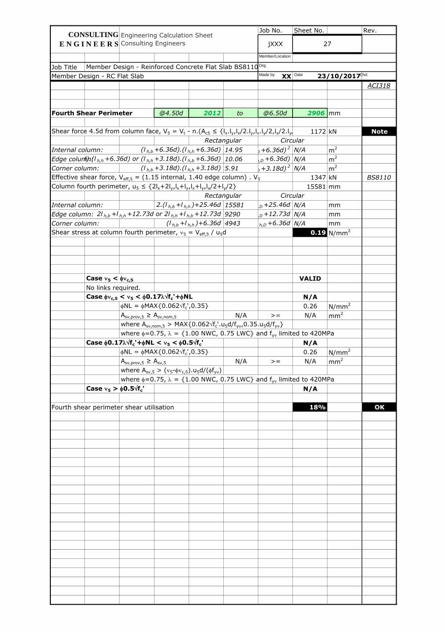
Fourth Shear Perimeter @4.50d 2012 4 @6.50d 2906 mm
Shear force 4.5d from column face, V5 = Vt - n.(Ac5 ≤ {lx.ly,lx/2.ly,lx.ly/2,lx/2.ly/2}) 1172 kN Note
Internal column: (l h,b +6.36d).(l h,h +6.36d) 14.95 (l h,D +6.36d)2 N/A m
2
Edge column:(l h,b +3.18d).(l h,h +6.36d) or (l h,h +3.18d).(l h,b +6.36d) 10.06(l h,D +3.18d).(l h,D +6.36d) N/A m2
Corner column: (l h,b +3.18d).(l h,h +3.18d) 5.91 (l h,D +3.18d)2 N/A m
2
Effective shear force, Veff,5 = (1.15 internal, 1.40 edge column) . V5 1347 kN BS8110
Column fourth perimeter, u5 ≤ {2lx+2ly,lx+ly,lx+ly,lx/2+ly/2} 15581 mm
Internal column: 2.(l h,b +l h,h )+25.46d 15581 4l h,D +25.46d N/A mm
Edge column: 2l h,b +l h,h +12.73d or 2l h,h +l h,b +12.73d 9290 3l h,D +12.73d N/A mm
Corner column: (l h,b +l h,h )+6.36d 4943 2l h,D +6.36d N/A mm
Shear stress at column fourth perimeter, n5 = Veff,5 / u5d 0.19 N/mm2
Case n5 < fnc,5 VALID
No links required.
Case fnc,5 < n5 < f0.17lfc'+fNL N/A
fNL = fMAX{0.062fc',0.35} 0.26 N/mm2
Asv,prov,5 ≥ Asv,nom,5 N/A >= N/A mm2
where Asv,nom,5 > MAX{0.062fc'.u5d/fyv,0.35.u5d/fyv}
where f=0.75, l = {1.00 NWC, 0.75 LWC} and fyv limited to 420MPa
Case f0.17lfc'+fNL < n5 < f0.5fc' N/A
fNL = fMAX{0.062fc',0.35} 0.26 N/mm2
Asv,prov,5 ≥ Asv,5 N/A >= N/A mm2
where Asv,5 > (n5-fnc,5).u5d/(ffyv)
where f=0.75, l = {1.00 NWC, 0.75 LWC} and fyv limited to 420MPa
Case n5 > f0.5fc' N/A
Fourth shear perimeter shear utilisation 18% OK
Rectangular Circular
Rectangular Circular
Member Design - Reinforced Concrete Flat Slab BS8110, ACI318 v2017.01.xlsm
Member Design - RC Flat Slab 23/10/2017
27
CONSULTING
E N G I N E E R S
Engineering Calculation Sheet
Consulting Engineers jXXX
Made by Date Chd.
Drg.
Member/Location
to
Job No. Sheet No. Rev.
Job Title
XX
BS8110
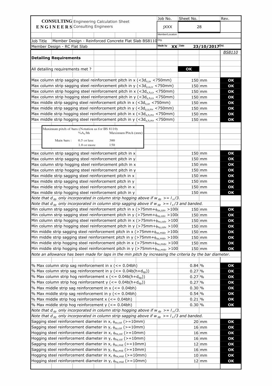
Detailing Requirements
All detailing requirements met ? OK
Max column strip sagging steel reinforcement pitch in x (<3dx,s, <750mm) 150 mm OK
Max column strip sagging steel reinforcement pitch in y (<3dy,s,c, <750mm) 150 mm OK
Max column strip hogging steel reinforcement pitch in x (<3dx,h,c, <750mm) 150 mm OK
Max column strip hogging steel reinforcement pitch in y (<3dy,h,c, <750mm) 150 mm OK
Max middle strip sagging steel reinforcement pitch in x (<3dx,s, <750mm) 150 mm OK
Max middle strip sagging steel reinforcement pitch in y (<3dy,s,m, <750mm) 150 mm OK
Max middle strip hogging steel reinforcement pitch in x (<3dx,h,m, <750mm) 150 mm OK
Max middle strip hogging steel reinforcement pitch in y (<3dy,h,m, <750mm) 150 mm OK
Max column strip sagging steel reinforcement pitch in x 150 mm OK
Max column strip sagging steel reinforcement pitch in y 150 mm OK
Max column strip hogging steel reinforcement pitch in x 150 mm OK
Max column strip hogging steel reinforcement pitch in y 150 mm OK
Max middle strip sagging steel reinforcement pitch in x 150 mm OK
Max middle strip sagging steel reinforcement pitch in y 150 mm OK
Max middle strip hogging steel reinforcement pitch in x 150 mm OK
Max middle strip hogging steel reinforcement pitch in y 150 mm OK
Note that d dp only incorporated in column strip hogging above if w dp >= l x /3.
Note that d dp only incorporated in column strip sagging above if w dp >= l x /3 and banded.
Min column strip sagging steel reinforcement pitch in x (>75mm+fsx,col, >100mm+fsx,col if T40)150 mm OK
Min column strip sagging steel reinforcement pitch in y (>75mm+fsy,col, >100mm+fsy,col if T40)150 mm OK
Min column strip hogging steel reinforcement pitch in x (>75mm+fhx,col, >100mm+fhx,col if T40)150 mm OK
Min column strip hogging steel reinforcement pitch in y (>75mm+fhy,col, >100mm+fhy,col if T40)150 mm OK
Min middle strip sagging steel reinforcement pitch in x (>75mm+fsx,mid, >100mm+fsx,mid if T40)150 mm OK
Min middle strip sagging steel reinforcement pitch in y (>75mm+fsy,mid, >100mm+fsy,mid if T40)150 mm OK
Min middle strip hogging steel reinforcement pitch in x (>75mm+fhx,mid, >100mm+fhx,mid if T40)150 mm OK
Min middle strip hogging steel reinforcement pitch in y (>75mm+fhy,mid, >100mm+fhy,mid if T40)150 mm OK
Note an allowance has been made for laps in the min pitch by increasing the criteria by the bar diameter.
% Max column strip sag reinforcement in x (<= 0.04bh) 0.84 % OK
% Max column strip sag reinforcement in y (<= 0.04b(h+ddp)) 0.27 % OK
% Max column strip hog reinforcement x (<= 0.04b(h+ddp)) 0.27 % OK
% Max column strip hog reinforcement y (<= 0.04b(h+ddp)) 0.27 % OK
% Max middle strip sag reinforcement in x (<= 0.04bh) 0.30 % OK
% Max middle strip sag reinforcement in y (<= 0.04bh) 0.54 % OK
% Max middle strip hog reinforcement x (<= 0.04bh) 0.21 % OK
% Max middle strip hog reinforcement y (<= 0.04bh) 0.30 % OK
Note that d dp only incorporated in column strip hogging above if w dp >= l x /3.
Note that d dp only incorporated in column strip sagging above if w dp >= l x /3 and banded.
Sagging steel reinforcement diameter in x, fsx,col (>=10mm) 20 mm OK
Sagging steel reinforcement diameter in y, fsy,col (>=10mm) 16 mm OK
Hogging steel reinforcement diameter in x, fhx,col (>=10mm) 16 mm OK
Hogging steel reinforcement diameter in y, fhy,col (>=10mm) 16 mm OK
Sagging steel reinforcement diameter in x, fsx,mid (>=10mm) 12 mm OK
Sagging steel reinforcement diameter in y, fsy,mid (>=10mm) 16 mm OK
Hogging steel reinforcement diameter in x, fhx,mid (>=10mm) 10 mm OK
Hogging steel reinforcement diameter in y, fhy,mid (>=10mm) 12 mm OK
Member Design - RC Flat Slab 23/10/2017
jXXX 28
Member Design - Reinforced Concrete Flat Slab BS8110, ACI318 v2017.01.xlsm
Engineering Calculation Sheet
Consulting Engineers
CONSULTING
E N G I N E E R S
Made by Date Chd.
Drg.
Member/Location
Date Chd. Made by
Job No. Sheet No. Rev.
Job Title
XX
BS8110
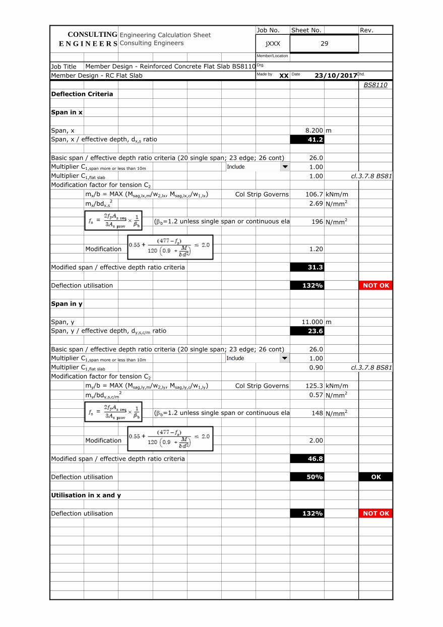
Deflection Criteria
Span in x
Span, x 8.200 m
Span, x / effective depth, dx,s ratio 41.2
Basic span / effective depth ratio criteria (20 single span; 23 edge; 26 cont) 26.0
Multiplier C1,span more or less than 10m 1.00
Multiplier C1,flat slab 1.00 cl.3.7.8 BS8110
Modification factor for tension C2
mx/b = MAX (Msag,lx,m/w2,lx, Msag,lx,c/w1,lx) Col Strip Governs 106.7 kNm/m
mx/bdx,s2 2.69 N/mm
2
(bb=1.2 unless single span or continuous elastic) 196 N/mm2
Modification 1.20
Modified span / effective depth ratio criteria 31.3
Deflection utilisation 132% NOT OK
Span in y
Span, y 11.000 m
Span, y / effective depth, dy,s,c/m ratio 23.6
Basic span / effective depth ratio criteria (20 single span; 23 edge; 26 cont) 26.0
Multiplier C1,span more or less than 10m 1.00
Multiplier C1,flat slab 0.90 cl.3.7.8 BS8110
Modification factor for tension C2
my/b = MAX (Msag,ly,m/w2,ly, Msag,ly,c/w1,ly) Col Strip Governs 125.3 kNm/m
my/bdy,s,c/m2 0.57 N/mm
2
(bb=1.2 unless single span or continuous elastic) 148 N/mm2
Modification 2.00
Modified span / effective depth ratio criteria 46.8
Deflection utilisation 50% OK
Utilisation in x and y
Deflection utilisation 132% NOT OK
Member Design - Reinforced Concrete Flat Slab BS8110, ACI318 v2017.01.xlsm
Member Design - RC Flat Slab 23/10/2017
CONSULTING
E N G I N E E R S
Engineering Calculation Sheet
Consulting Engineers jXXX 29
Made by Date Chd.
Drg.
Member/Location
Job No. Sheet No. Rev.
Job Title
XX
BS8110
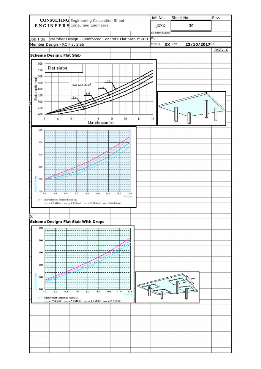
Scheme Design: Flat Slab
cl.3.7.8 BS8110
cl.3.7.8 BS8110
Scheme Design: Flat Slab With Drops
jXXX 30
23/10/2017
Member Design - Reinforced Concrete Flat Slab BS8110, ACI318 v2017.01.xlsm
Member Design - RC Flat Slab
Engineering Calculation Sheet
Consulting Engineers
CONSULTING
E N G I N E E R S
Made by Date Chd.
Drg.
Member/Location
Job No. Sheet No. Rev.
Job Title
XX
BS8110
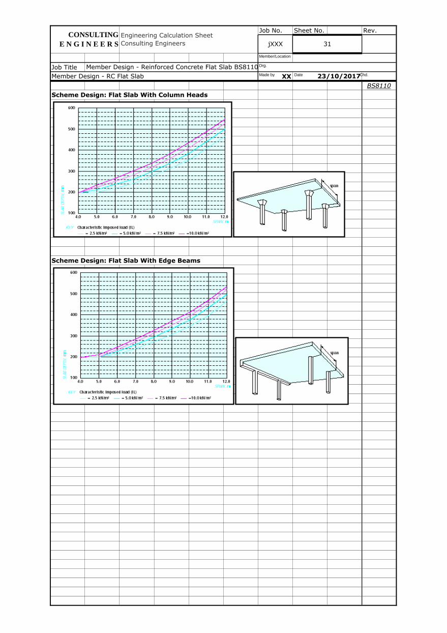
Scheme Design: Flat Slab With Column Heads
Scheme Design: Flat Slab With Edge Beams
31
Member Design - Reinforced Concrete Flat Slab BS8110, ACI318 v2017.01.xlsm
Member Design - RC Flat Slab 23/10/2017
CONSULTING
E N G I N E E R S
Engineering Calculation Sheet
Consulting Engineers jXXX
Made by Date Chd.
Drg.
Member/Location
Job No. Sheet No. Rev.
Job Title
XX
BS8110
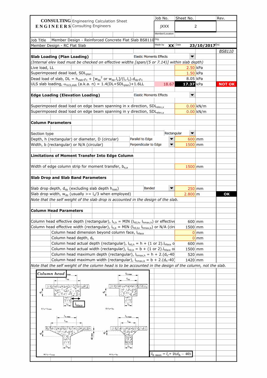
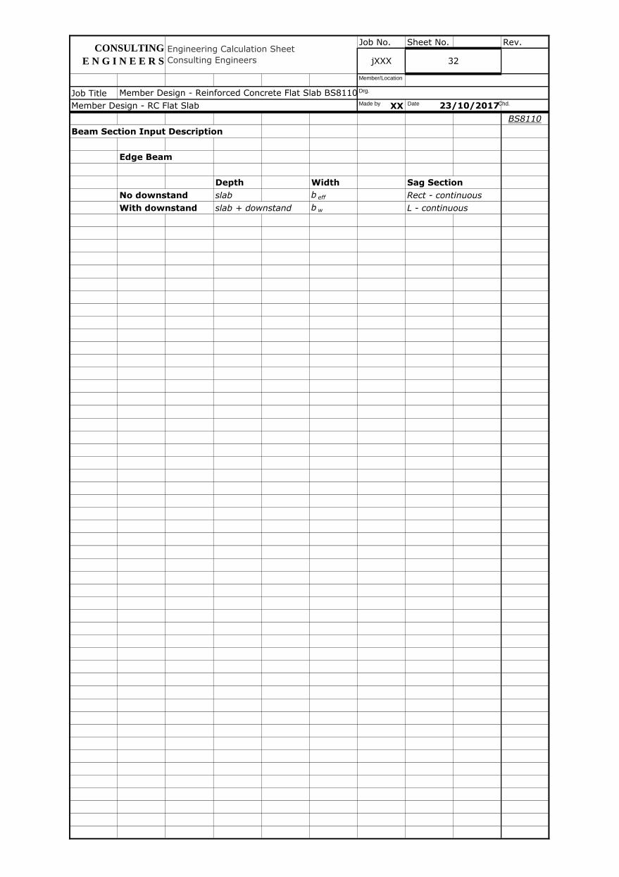
Beam Section Input Description
Edge Beam
Depth Width Sag Section
No downstand slab b eff Rect - continuous
With downstand slab + downstand b w L - continuous
Member Design - RC Flat Slab 23/10/2017
CONSULTING
E N G I N E E R S
Engineering Calculation Sheet
Consulting Engineers jXXX 32
Member Design - Reinforced Concrete Flat Slab BS8110, ACI318 v2017.01.xlsmMade by Date Chd.
Drg.
Member/Location
Job No. Sheet No. Rev.
Job Title
XX
BS8110
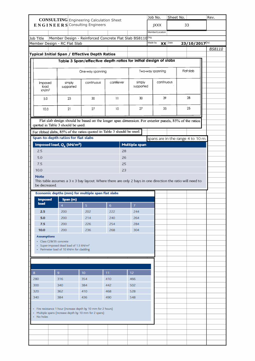
Typical Initial Span / Effective Depth Ratios
Member Design - Reinforced Concrete Flat Slab BS8110, ACI318 v2017.01.xlsm
Member Design - RC Flat Slab 23/10/2017
CONSULTING
E N G I N E E R S
Engineering Calculation Sheet
Consulting Engineers jXXX 33
Made by Date Chd.
Drg.
Member/Location
Job No. Sheet No. Rev.
Job Title
XX
BS8110
Member Design - RC Flat Slab 23/10/2017
CONSULTING
E N G I N E E R S
Engineering Calculation Sheet
Consulting Engineers jXXX 34
Member Design - Reinforced Concrete Flat Slab BS8110, ACI318 v2017.01.xlsmMade by Date Chd.
Drg.
Member/Location
Job No. Sheet No. Rev.
Job Title
XX
BS8110
jXXX 35
Member Design - Reinforced Concrete Flat Slab BS8110, ACI318 v2017.01.xlsm
Member Design - RC Flat Slab 23/10/2017
Engineering Calculation Sheet
Consulting Engineers
CONSULTING
E N G I N E E R S
Made by Date Chd.
Drg.
Member/Location


![Spandrel or edge beam - San Francisco State · PDF fileEffective flange width T-Beam Ana] sis T-beams are analyzed similarly to rectangular beams, except the compression area is a](https://img.pdfslide.net/doc/110x75/5ab0b2757f8b9ac3348b7bc9/spandrel-or-edge-beam-san-francisco-state-flange-width-t-beam-ana-sis-t-beams.jpg)