Embed Size (px)
Citation preview

TABLE OF CONTENT1. Objective2. Scope3. Responsibility (Client and manufacturer)4. URS (User Requirement Specification)5. Machine description 6. Technical specification of sub components/brought out items. 7. Specification of Automation.8. Machine operation control through PLC9. Details of power consumption10. Material of construction of component11. Test certificates/Inspection reports12. Surface Area of the product contact parts13. Brief Process Description14. Safety-Interlocks/Alarms messages15. Load calibration chart16. Lubrication requirements17. FAT procedure18. Change control procedure19. Appendix
1.0 OBJECTIVE:
To design, engineer, and supply the Cadmach CPD-II-37 station with Bi Layer attachment as per cGMP and cGEP guidelines and to provide assurance that the machine is manufactured as per the URS and it complies with the Scope of Supply.
To prove that each operation proceeds as per the design specification and the tolerances prescribed there in the document, are the same at

utmost transparency. Validation procedure is set for complete satisfaction of the customer & building confidence of the user about the machine.
2.0 SCOPE:
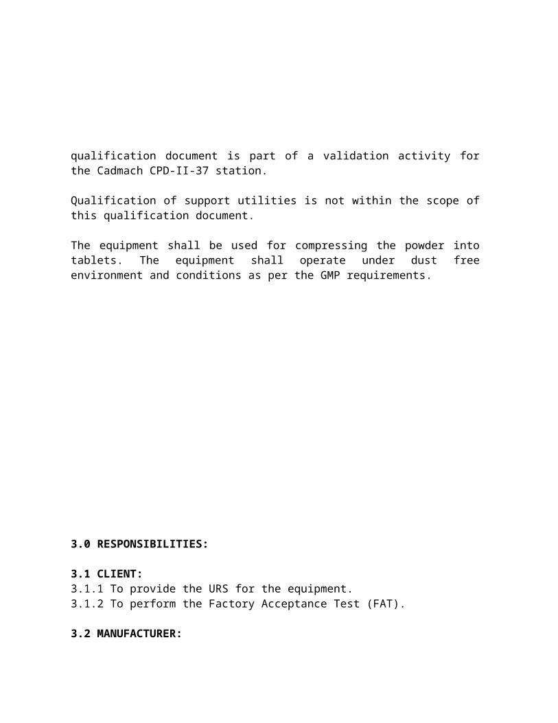
The scope of this qualification document is limited to the Design Qualification of Cadmach CPD-II-37 station with Bi Layer Attachment for M/s USV Limited, in Daman. This qualification document is part of a validation activity for the Cadmach CPD-II-37 station.
Qualification of support utilities is not within the scope of this qualification document.
The equipment shall be used for compressing the powder into tablets. The equipment shall operate under dust free environment and conditions as per the GMP requirements.
3.0 RESPONSIBILITIES:
3.1 CLIENT:3.1.1 To provide the URS for the equipment.3.1.2 To perform the Factory Acceptance Test (FAT).
3.2 MANUFACTURER:3.2.1 To design, engineer and provide the complete technical details of the equipment pertaining to its design qualification viz.
3.2.1.a Machine overview,3.2.1.b Specifications of the sub-components/ bought out items, and their
make, model & quantity, and backup records/ brochures,3.2.1.c Details of Utilities,3.2.1.d Material of construction of all components3.2.1.e Brief process description3.2.1.f Safety features.
3.2.2 To facilitate the client for the Factory acceptance test of the machine at their works/ site.
3.2.3 To confirm the safe delivery of the equipment to the user site.
3.2.4 To ensure that no un-authorized and / or unrecorded design modifications shall take place. If at any point in time, any change is desired in the mutually agreed design, Change control procedure shall be followed and documented.

3.2.5 To ensure the proper installation and commissioning of the equipment.
4.0 URS ( User Requirement Specification) :
Please refer attached Annexure No. DQ/ANX/03 for the User Requirement Specification.
5.0 MACHINE DESCRIPTION
5.1 Process Equipment Description
The Cadmach CPD-II-37 station with Bi Layer Attachment, a double rotary tablet press, is a versatile machine in the range of tabletting. It is also

incorporated with the force-feeding arrangement, Lubrication (Intermittent + Continuous), electromagnetic clutch and Programmable Logic Controller. The Bi Layer attachment facilitates in producing twin colour tablets.
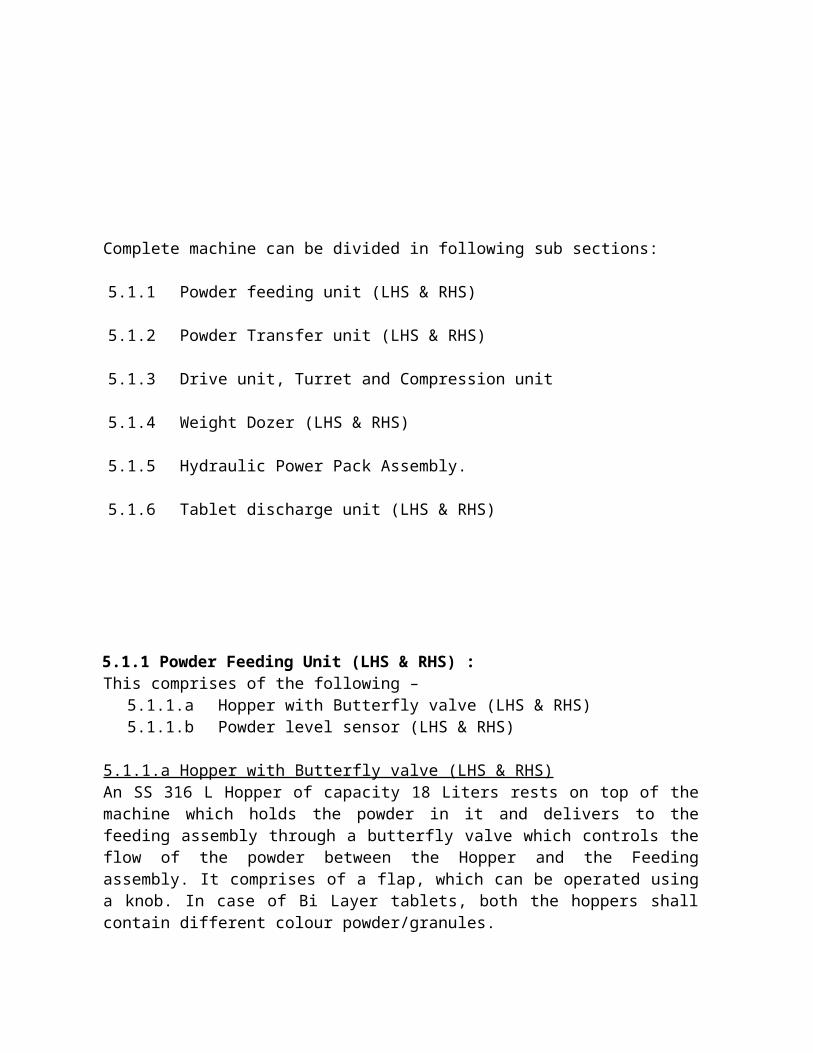
Complete machine can be divided in following sub sections:
5.1.1Powder feeding unit (LHS & RHS)
5.1.2Powder Transfer unit (LHS & RHS)
5.1.3Drive unit, Turret and Compression unit
5.1.4Weight Dozer (LHS & RHS)
5.1.5Hydraulic Power Pack Assembly.
5.1.6Tablet discharge unit (LHS & RHS)
5.1.1 Powder Feeding Unit (LHS & RHS) : This comprises of the following –
5.1.1.a Hopper with Butterfly valve (LHS & RHS)5.1.1.b Powder level sensor (LHS & RHS)
5.1.1.a Hopper with Butterfly valve (LHS & RHS) An SS 316 L Hopper of capacity 18 Liters rests on top of the machine which holds the powder in it and delivers to the feeding assembly through a butterfly valve which controls the flow of the powder between the Hopper and the Feeding assembly. It comprises of a flap, which can be operated using a knob. In case of Bi Layer tablets, both the hoppers shall contain different colour powder/granules.
5.1.1.b Powder Level Sensor (LHS & RHS): - This is set on a sight glass fit to the hopper. The setting is done using two adjustable nuts. As soon as
the powder in the hopper drops down the level, the sensor senses the same and gives the respective signal to the PLC and stops the machine.
5.1.2 Powder Transfer Unit: - This comprises of the following –
5.1.2.a Inlet Connector (LHS & RHS)5.1.2 b Force Feeder Assembly (LHS & RHS)
5.1.2.a Inlet Connector (LHS & RHS) It is a SS 316 L connector, which links the Hopper and the Force feeder.
5.1.2.b Force Feeder Assembly (LHS & RHS) It comprises of
5.1.2.b.i Force Feeder5.1.2.b.ii Tail over die, scrappers and feeder5.1.2.b.iii Nozzle outlet for suction.
5.1.2.b.i. Force Feeder The force feeder has two counter rotating paddles of SS 316 L, driven by reduction gearbox and variable frequency AC drive motor. The pressing material enters the feeder in the middle between the two paddles. With the feeder in the “MANUAL MODE”, the force feeder is operated for initial filling prior to rotating the machine and in “AUTO MODE”; the force feeder will run along with the machine. While machine is in production, always put the feeder in “AUTO MODE”.
5.1.2.b.ii Tail over die, scrappers and feeder The tail over die is an essential feature of the high-speed tablet press. The function of the tail over die is to keep the filled die covered until the last moment before the upper punch enters the die. Failure to keep the die covered will result in granules spilling out of the die with subsequent variation of the tablet weight. The tail over die is fitted freely over the turret die table and is pressed against the die table by spring action. Ensure that the bottom surface of the tail over die rests flat and matches with the die table.

The spring-loaded scrappers are inserted in the scrapper support bracket and tail over die respectively. The springs press the scrappers against the turret die table to scrap off. the tabletting powder
5.1.2.b.iii Nozzle outlet for suction This comprises of a PVC pipe that is connected to the dust extraction unit. The powder dust coming from the preceding feeder is completely sucked thereby avoiding mixing of granules & reduce the dust generation.
5.1.3 Drive unit, Turret and Compression Unit
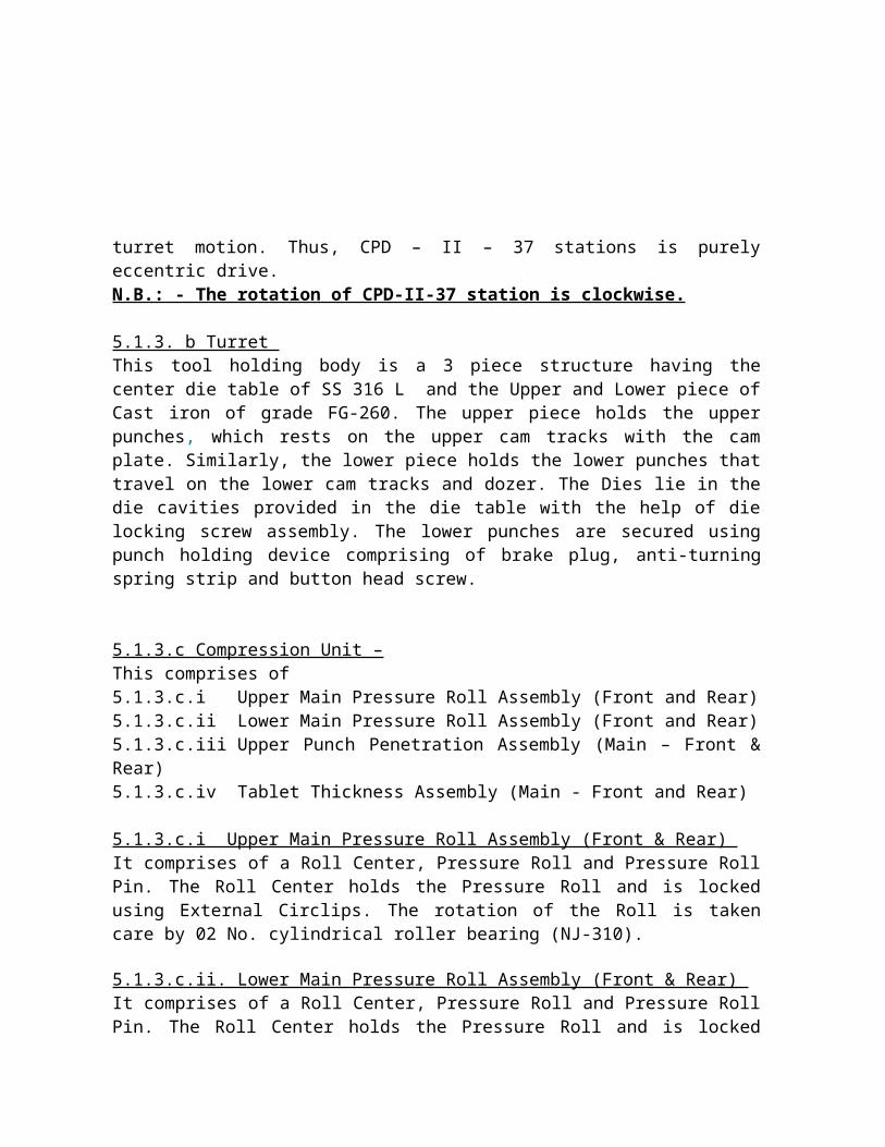
5.1.3.a Drive unit A main motor of 7.5 HP drives a very high reduction gearbox unit using an electromagnetic clutch and a timing belt. The gearbox unit consists of a Phosphorus bronze (SAE65) worm wheel and a Worm shaft of SAE 8620 (with case hardening having 58 – 62 HRC). The worm wheel shaft holds the Pinion. The turret has an internal helical ring, which meshes externally to the pinion. The rotation of the pinion is responsible for turret motion. Thus, CPD – II – 37 stations is purely eccentric drive.N.B.: - The rotation of CPD-II-37 station is clockwise. 5.1.3. b Turret This tool holding body is a 3 piece structure having the center die table of SS 316 L and the Upper and Lower piece of Cast iron of grade FG-260. The upper piece holds the upper punches, which rests on the upper cam tracks with the cam plate. Similarly, the lower piece holds the lower punches that travel on the lower cam tracks and dozer. The Dies lie in the die cavities provided in the die table with the help of die locking screw assembly. The lower punches are secured using punch holding device comprising of brake plug, anti-turning spring strip and button head screw.
5.1.3.c Compression Unit – This comprises of5.1.3.c.i Upper Main Pressure Roll Assembly (Front and Rear)5.1.3.c.ii Lower Main Pressure Roll Assembly (Front and Rear)5.1.3.c.iii Upper Punch Penetration Assembly (Main – Front & Rear)

5.1.3.c.iv Tablet Thickness Assembly (Main - Front and Rear)
5.1.3.c.i Upper Main Pressure Roll Assembly (Front & Rear) It comprises of a Roll Center, Pressure Roll and Pressure Roll Pin. The Roll Center holds the Pressure Roll and is locked using External Circlips. The rotation of the Roll is taken care by 02 No. cylindrical roller bearing (NJ-310).
5.1.3.c.ii. Lower Main Pressure Roll Assembly (Front & Rear) It comprises of a Roll Center, Pressure Roll and Pressure Roll Pin. The Roll Center holds the Pressure Roll and is locked using External Circlips.The rotation of the Roll is taken care by 02 Nos. cylindrical roller bearing (NJ-2310).
5.1.3.c.iii Upper Punch Penetration Assembly (Main – Front & Rear) This is the assembly, which is responsible for the entry height of the upper punch in the die. Whenever the wheel of upper punch penetration is rotated, the entire upper pressure assembly with the carrier along with the lower pressure assembly is moved up and down. Always care needs to be taken to set the upper punch penetration initially and only then the thickness.
5.1.3.c.iv Tablet Thickness Assembly (Main – Front & Rear) This is the assembly, which is responsible in deciding the tablet thickness. The upward and downward movement of the lower pressure carrier assembly varies the thickness.
5.1.4 Weight Dozer (LHS and RHS)This assembly is responsible for adjusting the weight of the tablet by varying the depth of fill. The depth of fill is adjusted by the upward and downward movement of the weight adjusting head through a dozer adjusting screw with the help of dial.
5.1.5 Hydraulic Power Pack Assembly This system controls the safety overload mechanism, which governs the maximum pressure, level, at which particular tablets are being made. The oil reservoir for this system is located in front corner within lower cabinet.
It can be accessed by removing the lower side guard (LH). The oil level in the reservoir should be checked regularly through the oil level indicator.
5.1.6 Tablet discharge unit This comprises of-5.1.6.a Ejection Cam (LHS & RHS)5.1.6.b Tablet take off plate assembly (LHS & RHS)5.1.6.c Tablet discharge chute (LHS & RHS).
5.1.6.a. Ejection Cam (LHS & RHS) The lower punch glides on the ejection cam and ejects the tablet. The height of the ejection cam needs to be set in such a way that the tip of the lower punch is slightly above the die so as to avoid tablet-chipping problem. In case of Bi Layer operation, the ejection cam and fill cam of the LHS are removed. This is done to facilitate the filling of the second layer on the initial layer.
5.1.6.b Tablet take off plate assembly (LHS & RHS) As soon as the tablet is ejected out it strikes the tablet take off plate assembly, which directs the tablet to the discharge chute. Care should be taken so that the tip of the lower punch does not strike the tablet scrapper assembly. In case of Bi Layer operation, this assembly is present on the RHS feeder only as there is no ejection on LHS.
5.1.6.c Tablet discharge chute (LHS & RHS) It is made of SS 316 L with acrylic cover. Tablets slide out through this chute to the container. In case of Bi Layer operation, only one discharge chute is present i.e., on the RHS.
6.0 Technical specification of sub components / bought-out items.
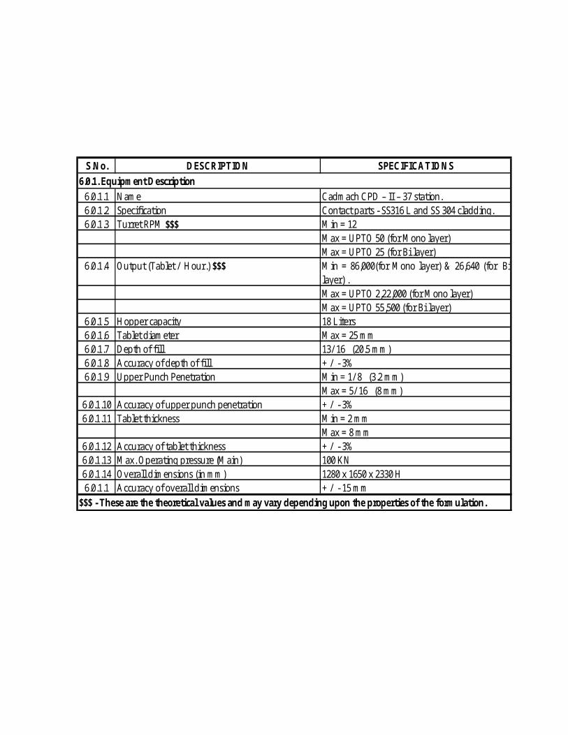
S.No. DESCRIPTION SPECIFICATIONS
6.0.1.1 Name Cadmach CPD – II – 37 station.6.0.1.2 Specification Contact parts - SS316 L and SS 304 cladding.6.0.1.3 Turret RPM $$$ Min = 12
Max = UPTO 50 (for Mono layer)Max = UPTO 25 (for Bi layer)
6.0.1.4 Output (Tablet / Hour.) $$$ Min = 86,000(for Mono layer) & 26,640 (for Bilayer) . Max = UPTO 2,22,000 (for Mono layer)Max = UPTO 55,500 (for Bi layer)
6.0.1.5 Hopper capacity 18 Liters6.0.1.6 Tablet diameter Max = 25 mm6.0.1.7 Depth of fill 13/ 16” (20.5 mm)6.0.1.8 Accuracy of depth of fill + / - 3%6.0.1.9 Upper Punch Penetration Min = 1/ 8” (3.2 mm)
Max = 5/ 16” (8 mm)6.0.1.10 Accuracy of upper punch penetration + / - 3%6.0.1.11 Tablet thickness Min = 2 mm
Max = 8 mm6.0.1.12 Accuracy of tablet thickness + / - 3%6.0.1.13 Max. Operating pressure (Main) 100 KN6.0.1.14 Overall dimensions (in mm) 1280 x 1650 x 2330 H 6.0.1.1 Accuracy of overall dimensions + / - 15 mm
$$$ - These are the theoretical values and may vary depending upon the properties of the formulation.
6.0.1. Equipment Description
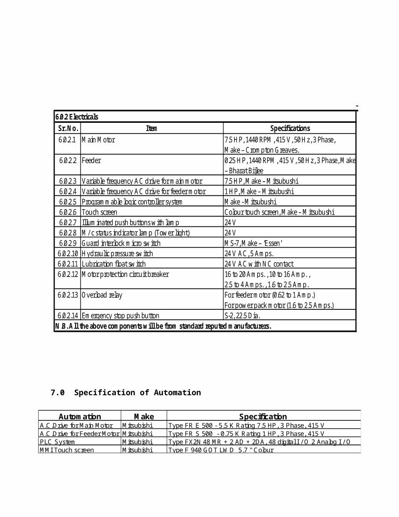
Sr. No. Item Specifications7.5 HP, 1440 RPM, 415 V, 50 Hz, 3 Phase, Make – Crompton Greaves.
6.0.2.2 Feeder 0.25HP, 1440RPM, 415V, 50Hz, 3Phase, Make– Bharat Bijlee
6.0.2.3 Variable frequency AC drive for main motor 7.5 HP, Make – Mitsubushi6.0.2.4 Variable frequency AC drive for feeder motor 1 HP, Make – Mitsubushi6.0.2.5 Programmable logic controller system Make - Mitsubushi6.0.2.6 Touch screen Colour touch screen, Make – Mitsubushi6.0.2.7 Illuminated push buttons with lamp 24 V6.0.2.8 M/ c status indicator lamp (Tower light) 24 V6.0.2.9 Guard interlock micro switch MS-7, Make – ‘Essen’6.0.2.10 Hydraulic pressure switch 24 V AC, 5 Amps.6.0.2.11 Lubrication float switch 24 V AC with NC contact
16 to 20 Amps. , 10 to 16 Amp. ,2.5 to 4 Amps. , 1.6 to 2.5 Amp.For feeder motor (0.62 to 1 Amp.)For power pack motor (1.6 to 2.5 Amps.)
6.0.2.14 Emergency stop push button S-2, 22.5 Dia.
6.0.2 Electricals
6.0.2.1 Main Motor
N.B. All the above components will be from standard reputed manufacturers.
6.0.2.12 Motor protection circuit breaker
6.0.2.13 Overload relay
7.0 Specification of Automation
Automation Make Specification A.C.Drive for Main Motor Mitsubishi Type FR E 500 - 5.5 K Rating 7.5 HP, 3 Phase, 415 VA.C.Drive for Feeder Motor Mitsubishi Type FR S 500 - 0.75 K Rating 1 HP, 3 Phase, 415 VPLC System Mitsubishi Type FX2N 48 MR + 2 AD + 2DA, 48 digital I / O 2 Analog I / O MMI Touch screen Mitsubishi Type F 940 GOT LWD 5.7 " Colour

Specification of programmable logic control systems :
8.0 Machine operation control through PLC Switch on the mains, `Welcome’ screen will be displayed Enter valid password, `Main menu’ screen will be displayed Three levels of password will be provided as follows:
a) Operator Levelb) Supervisor Levelc) Manager Level
Press machine control touch button, detailed `Machine control menu’ screen will be displayed
Press turret control touch button, detailed `Turret control menu’ screen will be displayed
Press feeder control touch button, detailed `Feeder control menu’ screen will be displayed
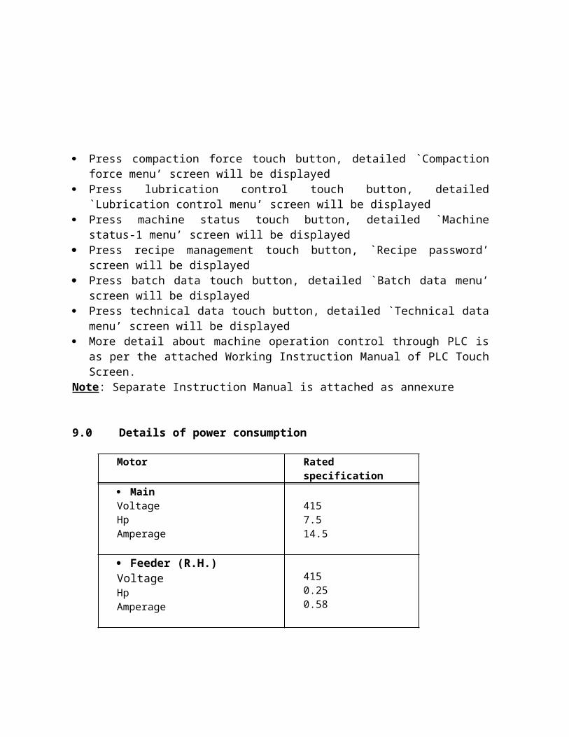
Press compaction force touch button, detailed `Compaction force menu’ screen will be displayed
Press lubrication control touch button, detailed `Lubrication control menu’ screen will be displayed
Press machine status touch button, detailed `Machine status-1 menu’ screen will be displayed
Number of Input/Output 24 InputsNumber of Input/Output 24 outputsLine Power 100 - 240 V AC 50/60 HZInrush current 0.2 A Input circuit type 24 DC sink / sourceOutput circuit type MR - ES / UL (Relay output)Operating temperature + 0o to 55O o c ( + 32 O F to 131 o F ) AmbientStorage temperature - 20 o C to +70 o C( -4 O F to +158 o F) AmbientOperating humidity 5 % to 95 % relative humidity ( Non- condensing)Vibration Operating : 10 to 57 Hz, 0.035 mm. Hlaf
Amplitude - 57 to 150 Hz. 4.9 n / sec 2 --> acceleration
Shock Resistance EN 68 - 2- 27, 11 MS, 147 m/sec 2 -->- acceleration.
Agency certification CE, UL / cUL, UL 508. CE complaint for all applicable directives.
Terminal screw torque 0.3 to 0.6 Nm I.e. 3 to 6 Kgf - cm
Make : MITSUBHISHI, Catalogue No. FX2N - 48 MR - ES / UA
Press recipe management touch button, `Recipe password’ screen will be displayed
Press batch data touch button, detailed `Batch data menu’ screen will be displayed
Press technical data touch button, detailed `Technical data menu’ screen will be displayed
More detail about machine operation control through PLC is as per the attached Working Instruction Manual of PLC Touch Screen.
Note: Separate Instruction Manual is attached as annexure
9.0 Details of power consumption
Motor Rated specification
MainVoltageHpAmperage
4157.514.5
Feeder (R.H.)VoltageHpAmperage
4150.250.58
Feeder (L.H.)VoltageHpAmperage
4150.250.58
Power packVoltageHpAmperage
41511.8
Total power consumption for main machine: 9 Kw
10. 0 Material of Construction of component
Description Location MOCTurreta) Upper / Lower pieceb) Die table
Upper cabinetFG-260SS 316 L
Pressure Roll Roll Carrier OHNSWorm Shaft Main drive
Gear BoxSAE 8620 with case hardening having 58-62 HRC
Worm Wheel (Main Drive)
Main drive Gear Box
Phosphorus Bronze(SAE65)
Worm Shaft Feeder drive Gear Box
Mild Steel
Worm Wheel (Feeder Drive)
Feeder Gear Box
Phosphorus Bronze
Feeder housing Upper Cabinet
Gun Metal
Paddle for force feeder
Feeder housing
SS 316L
Hopper Roof SS 316LDischarge chute Near die table SS 316LLower guards Lower cabinet SS 304
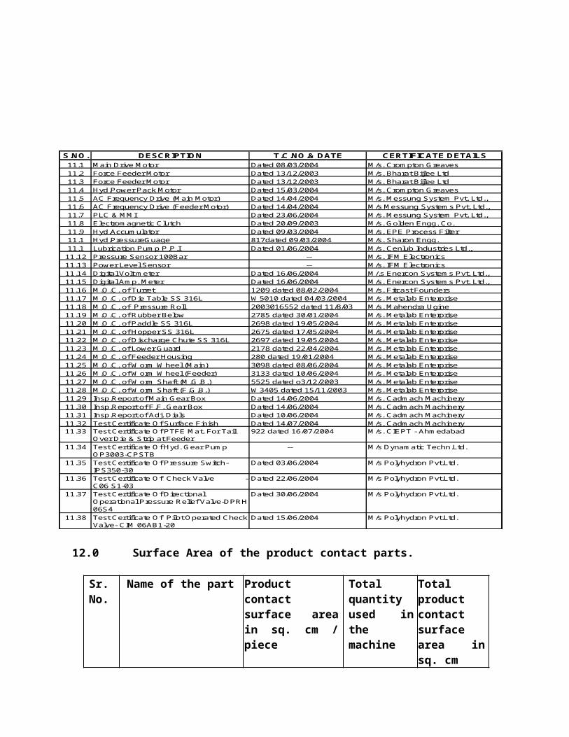
11.0 Test certificates / Inspection reports.

S.NO. DESCRIPTION T.C.NO.& DATE CERTIFICATE DETAILS11.1 Main Drive Motor Dated 08/03/2004 M/s. Crompton Greaves11.2 Force Feeder Motor Dated 13/12/2003 M/s. Bharat Bijlee Ltd11.3 Force Feeder Motor Dated 13/12/2003 M/s. Bharat Bijlee Ltd11.4 Hyd.Power Pack Motor Dated 15/03/2004 M/s. Crompton Greaves11.5 AC Frequency Drive (Main Motor) Dated 14/04/2004 M/s. Messung System Pvt. Ltd.,11.6 AC Frequency Drive (Feeder Motor) Dated 14/04/2004 M/s Messung Systems Pvt. Ltd.,11.7 PLC & MMI Dated 23/06/2004 M/s. Messung System Pvt. Ltd.,11.8 Electromagnetic Clutch Dated 20/09/2003 M/s. Golden Engg. Co.11.9 Hyd.Accumulator Dated 09/03/2004 M/s. EPE Process Filter11.1 Hyd.PressureGuage 817dated 09/03/2004 M/s. Sharon Engg.11.1 Lubrication Pump P.P.I Dated 01/06/2004 M/s. Cenlub Industries Ltd.,11.12 Pressure Sensor 100Bar -- M/s. IFM Electronics11.13 Power Level Sensor -- M/s. IFM Electronics11.14 Digital Volt meter Dated 16/06/2004 M/.s Enercon Systems Pvt. Ltd.,11.15 Digital Amp. Meter Dated 16/06/2004 M/s. Enercon Systems Pvt. Ltd.,11.16 M.O.C. of Turret 1209 dated 08/02/2004 M/s. Fitcast Founders11.17 M.O.C. of Die Table SS 316L W5010 dated 04/03/2004 M/s. Metalab Enterprise11.18 M.O.C. of Pressure Roll 2003016552 dated 11/8/03 M/s. Mahendra Ugine11.19 M.O.C. of Rubber Below 2785 dated 30/01/2004 M/s. Metalab Enterprise11.20 M.O.C. of Paddle SS 316L 2698 dated 19/05/2004 M/s. Metalab Enterprise11.21 M.O.C. of Hopper SS 316L 2675 dated 17/05/2004 M/s. Metalab Enterprise11.22 M.O.C. of Discharge Chute SS 316L 2697 dated 19/05/2004 M/s. Metalab Enterprise11.23 M.O.C. of Lower Guard 2178 dated 22/04/2004 M/s. Metalab Enterprise11.24 M.O.C. of Feeder Housing 280 dated 19/01/2004 M/s. Metalab Enterprise11.25 M.O.C. of Worm Wheel (Main) 3098 dated 08/06/2004 M/s. Metalab Enterprise11.26 M.O.C. of Worm Wheel (Feeder) 3133 dated 10/06/2004 M/s. Metalab Enterprise11.27 M.O.C. of Worm Shaft (M.G.B.) 5525 dated o3/12/2003 M/s. Metalab Enterprise11.28 M.O.C. of Worm Shaft (F.G.B.) W3405 dated 15/11/2003 M/s. Metalab Enterprise11.29 Insp.Report of Main Gear Box Dated 14/06/2004 M/s. Cadmach Machinery 11.30 Insp.Report of F.F. Gear Box Dated 14/06/2004 M/s. Cadmach Machinery 11.31 Insp.Report of Adj. Dials Dated 10/06/2004 M/s. Cadmach Machinery 11.32 Test Certificate Of Surface Finish Dated 14/07/2004 M/s. Cadmach Machinery 11.33 Test Certificate Of PTFE Mat. For Tail
Over Die & Strip at Feeder922 dated 16/07/2004 M/s. CIEPT - Ahmedabad
11.34 Test Certificate Of Hyd. Gear Pump OP3003-CPSTB
-- M/s Dynamatic Techn.Ltd.
11.35 Test Certificate Of Pressure Switch-IPS350-30
Dated 03/06/2004 M/s Polyhydron Pvt.Ltd.
11.36 Test Certificate Of Check Valve - C06 S1-03
Dated 22/06/2004 M/s Polyhydron Pvt.Ltd.
11.37 Test Certificate Of Directional Operational Pressure Relief Valve-DPRH 06S4
Dated 30/06/2004 M/s Polyhydron Pvt.Ltd.
11.38 Test Certificate Of Pilot Operated Check Valve- CIM 06AB1-20
Dated 15/06/2004 M/s Polyhydron Pvt.Ltd.
12.0 Surface Area of the product contact parts.
Sr. No.
Name of the part Product contact surface area in sq. cm / piece
Total quantity used in the machine
Total product contact surface area in sq. cm
1 Hopper 3078 2 6156
2 Extension for hopper
80 2 160
3 Flap for flow control
63 2 126
4 Bellows portion 66 2 1325 Inlet flange at bowl 256 2 5126 Bowl 96 2 1927 Feeder frame 561 2 11228 Paddle (First) 84 2 1689 Paddle (Second) 119 2 23810 Turret (Die table
only)1964 1 1964
11 Tablet chute (Inner)
448 2 896
12 Tablet chute (Outer)
719 2 1438
TOTAL FOR MACHINE
13104
N.B. The total product contact surface area of the parts of CPD-II-37 station machine with Bi – Layer attachment is 13104 sq. cm.
13.0 Brief Process Description.
13.1 Mono layer Operation
13.1.1 Force FeedingThe formulated powder in the hopper is pulled down using a Force Feeding arrangement consisting of rotary force feeders. The advantage of force feeder is, ensured die filling.
13.1.2 CompressionThe lower punches, which always remain in the die, hold the powder that is fed into the die, onto it. Further, due to the rotation of the turret, these punches move on the dozer assembly where only required quantity of the powder is held back and the rest is scrapped out. Punches then glide on

to pressure roll. At this stage the upper punch moves down the Upper cam track – Lowering, and then the pressure roll. Both the punches get pressurized under the pressure rolls. At this instant, due to the heavy compression force the tablet is formed. The excessive backpressure generated in this process is absorbed by the hydraulic cylinder, which is suspended onto the lower pressure roll carrier. After the tablet is formed inside the die, it needs to be ejected out. The lower punch moves further on to the ejection cam track and the tablet gets ejected out. At this stage, the upper punch moves onto the Upper cam track – Lifting and glides idly on the upper cam piece. After the tablet is ejected out, the lower punch moves in the lower cam track and comes beneath the feeder and the cycle continues. In one revolution, there is double ejection of tablets.
Tablet output / revolution = No. of stations x 2
13.2 Bi Layer Operation
13.2.1 Force FeedingIn case of Bilayer operation, two hoppers on the either sides would contain two different granules. The granules for the first layer are fed in using right hand feeder while for the second layer, using the left hand feeder.
13.2.2 CompressionThe granules for the first layer are fed into the dies by the right hand force feeder; the weight-adjusting cam regulates the correct amount. Excess granules are ejected from the die cavity and rejected through the excess power rejection slot. The material then passes between the front pressure rolls where the granules are tamped by the upper and lower punches. The degree of pressure applied should be just sufficient to produce a sharp demarcation between layers without affecting the bonding of the first and second layers. Adjusting the lower roll by the tablet thickness control can regulate the degree of tamping. The lightly compressed tablet, maintained at a height fixed by the amount of top punch penetration at the first compression station, passes under the second feeder and receives its second charge of granules. Again the appropriate weight-adjusting cam controls the fill of granules and the

surplus granules are ejected from the die cavity and rejected through the excess power rejection slot. But, it should be noted that the maximum depth of fill is controlled by the amount of the upper punch entry at the first compression. The dies, containing the two layers of material pass between the final compression rolls, which are adjusted to give the required final tablet hardness. The compressed tablet is ejected and deflected down the take-off chute (R.H.)
13.2.2 SamplingThe weight of the layers can be checked whilst the machine is in operation. To affect this the lower pressure roll of the first compression station is mounted on an eccentric pin, which has a gear cut on one end. This gear meshes with a rack mounted on the end of an air cylinder piston rod. When a weight check of the first layer is required the selector switch is put in “ON” condition. This actuates the air cylinder, which in turn pushes the rack upwards, and thus rotates the eccentric pin. The movement of the eccentric pin lifts the lower pressure roll and increases the hardness of the first layer. Due to this increased hardness no bonding between layers will take place during the final compression and the two layers will separate on ejection.
Weight of the first layer can be obtained by direct weighing the first layer sample and the weight of the second by subtraction the first layer sample tablet weight from the total weight of the completed two-layered tablet.
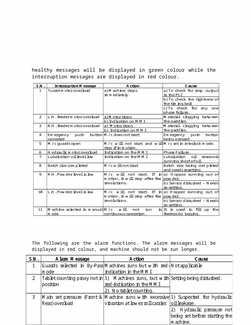
14.0 Safety - Interlocks / Alarms messages.Due to any of the following interlocking reasons the m/c will not start or will stop immediately, if in operation. The m/c healthy messages will be displayed in green colour while the interruption messages are displayed in red colour.
The following are the alarm functions. The alarm messages will be displayed in red colour, and machine should not be run longer.
S.N. Alarm Message Action Cause1 Guards selected in By-Pass
modeMachines runs but with red-indication in the MMI
Not applicable
1) Machines runs, but withred-indication in the MMI2) No tablet counting.
1) Suspected for hydraulicoil leakage.2) Hydraulic pressure notbeing set before starting themachine.
2 Tablet counting proxy not inposition
Setting being disturbed.
3 Main set pressure (Front &Rear) overload
Machine runs with excessivevibration at lower roll carrier
S.N. Interruptive Message Action Causea) To check for resp. outputin the PLCb) To check the tightness ofthe timing beltc) To check for any onephase failure.
a) Motor stopsb) Indication on MMIa) Motor stopsb) Indication on MMI
4 Emergency push buttonoperated
M/ c does not start Emergency push buttonbeing pressed.
5 M/ c guards open M/ c will not start and willstop if in motion.
M/ c set in interlock mode.
6 Hydraulic motor overload Indication on the MMI Phase Failure.7 Lubrication oil level low Indication on the MMI Lubrication oil reservoir
running short of oil.8 Batch size completed M/ c will not start Batch size being completed
and needs resetting.a) Hopper running out ofpowder.b) Sensor disturbed – Needsre-setting.a) Hopper running out ofpowder.b) Sensor disturbed – Needsre-setting.
11 Machine selected in manualmode
M/ c will not run incontinuous operation.
It is used to fill up thefeeders by jogging.
9 R.H. Powder level is low M/ c will not start. If inmotion, it will stop after fewrevolutions.
10 L.H. Powder level is low M/ c will not start. If inmotion, it will stop after fewrevolutions.
Material clogging betweenthe paddles.
3 R.H. feeder motor overload Material clogging betweenthe paddles.
1 Turret motor overload a) Machine stops immediately.
2 L.H. feeder motor overload

15.0 Load calibration chart
Punch force depends upon tablet size, shape, product characteristics and requirement of tablet hardness. The load on punches between two main compression rolls is developed by a hydraulic system. It should be set with the hydraulic system as required. The load on punches will be displayed on the digital force indicator in KN.Load on punches
between two main press rolls in Tons
Digital force indicator reading in
kN
Pressure gauge reading in kg/sq. cm
1 10 5.62 20 11.13 30 16.74 40 22.25 50 27.86 60 33.9
6.5 65 36.27 70 398 80 44.59 90 5010 100 55.6

16.0 Lubrication requirements
Sr. No. Description Location DurationHindustan
Petroleum makeShell make
1 Reservoir forcontinuous/ intermittent lubrication system.
Resides maindrive gearboxwithin lowercabinet.
Fill as required Enklo - 68 Omala – 220
2 Main drivegearbox.
Within lowercabinet.
About 2000working hrs.
Enklo - 68 Omala – 220
3 Gear box for forcefeeder drive
Within turretzone
About 2000working hrs.
Enklo - 68 Omala – 220
4 Oil drip cups On upperlowering cam,on turret guard.
Fill as required Enklo - 68 Omala – 220
5 Oil drip trays Besides lowerroll carrier
Fill as required Enklo - 68 Omala – 220
Lubricant
Sr. No. Description Location DurationHindustan
Petroleum makeShell make
Oil nipples fora. Tablet thickness control
Adjacent upperroll carrier
Apply with oneshot with oilgun daily
Enklo – 68 Omala – 220
b. Guide blocks for bottom link.
On cabinet topwithin uppercabinet
Apply with oneshot with oilgun daily
Enklo – 68 Omala – 220
c. Pivot pin at upper roll carrier.
Upper rollcarrier trunion
Apply one shotwith oil gundaily
Enklo – 68 Omala – 220
Grease nipples fora. Bearing Upper and Lower
roll centresApply one shotwith grease gunonce in a month
Servo gem – 3 Alvania RA grease
b. Bearing Main drive gearbox Apply one shotwith grease gunonce in a month
Servo gem - 3 Alvania RA grease
a. Main drive gearmotorb. Force feederdrive motorc. Hydraulic pumpmotor
9 Power pack systemoil reservoir
Besides bottom leg(rear L.H.) withinlower cabinet
Fill as required Enklo – 32 Tellus - 37
Apply manuallyafter about 3000working hours.
Servo gem – 3 Alvania RA grease
Lubricant
6
7
8 Motor bearing

17. 0 FAT PROCEDURE
Factory Acceptance Test Procedure shall be as follows:
After the completion of erection work of the machine, client shall be informed to perform the factory acceptance test (FAT)
Client shall perform the FAT at the manufacturer site and record all the data in the prescribed FAT document as per the details given below:

1. Test Criteria2. Design verification check list3. Deficiency and corrective action report4. Pre – installation requirements5. Final reports.
18.0 Change Control Procedure
Change in the agreed design shall be addressed through the well-defined change control procedure.
19.0 QUALIFICATION DOCUMENT REPORT APPROVAL
19.1 Summary:
19.2 Certifications:

20.0 APPENDIX
20.1 List of Abbreviations.
20.2 Reference documents
20.2.1 Manufacturers Brochure(s) / Manual(s)To be supplied with the installation qualification documents.
a) Instruction and Maintenance Manual.b) MOC Certificatesc) Test Reportsd) Inspection Reports
20.3 Annexure list
1 cGMP Current Good Manufacturing Practices. 16 Amps Amperes2 cGEP Current Good Engineering Practices 17 MS Micro Switch3 FAT Factory Acceptance Test 18 DC Direct Current4 URS User Requirement Specification 19 mA Milli Ampere5 PLC Programmable Logic Controller 20 W Watts6 SS Stainless Steel 21 C Degree Centigrade7 AC Alternating Current 22 F Degree Fahrenheit 8 HP Horse Power 23 Nm Newton-Meter9 HRC Rockwell Hardness 24 KW Kilo watts10 PB Phosphorus Bronze 25 OHNS Oil Hardened Non Shrinkage11 RPM Revolution Per Minute 26 Sq.cm Square centimeter12 mm Millimeter 27 N.B. Nota Benni13 KN Kilo Newton 28 Kg/Sq.cm Kilogram per square centimeter14 V Volt 29 M/c Machine.15 Hz Hertz

Sr. No.
Description Annexure Number
01 Equipment Brochure
DQ/ANX/01
02 Purchase Order DQ/ANX/0203 URS DQ/ANX/0304 Scope of supply DQ/ANX/0405 FAT Report DQ/ANX/0506 Inspection Report DQ/ANX/06
20.4 Drawing list
S.N. Description Drawing Number
01 G.A. Drawing for CPD-II-37 station with PLC system
DQ/ANX/07
02 Continuous and Intermittent lubrication
DQ/ANX/08