Embed Size (px)
Citation preview
ESTEC, October 200418TH European Thermal & ECLS Software Workshop
EMPRESARIOS AGRUPADOS
CARMEN GREGORI DE LA MALLAEAI
ESTEC, October 200418TH European Thermal & ECLS Software Workshop
EMPRESARIOS AGRUPADOS
CONTENTSCONTENTS
•• IntroductionIntroduction
•• LHP LibraryLHP Library
•• ExamplesExamples
•• Future ImprovementsFuture Improvements
ESTEC, October 200418TH European Thermal & ECLS Software Workshop
EMPRESARIOS AGRUPADOS
ESTEC, October 200418TH European Thermal & ECLS Software Workshop
EMPRESARIOS AGRUPADOS
INTRODUCTION (1)INTRODUCTION (1)
•• Loop heat pipes (LHP) are twoLoop heat pipes (LHP) are two--phase capillary heat phase capillary heat transfer devices that are becoming very interesting transfer devices that are becoming very interesting for space thermal control applications because of:for space thermal control applications because of:–– High power transport capabilityHigh power transport capability
–– High temperature stabilityHigh temperature stability
–– Fast and strong diode actionFast and strong diode action
–– Design flexibilityDesign flexibility
–– Robustness and reliabilityRobustness and reliability
ESTEC, October 200418TH European Thermal & ECLS Software Workshop
EMPRESARIOS AGRUPADOS
INTRODUCTION (2)INTRODUCTION (2)
•• Important Important modelization modelization efforts have been performed in efforts have been performed in order to predict thermal performances and transient order to predict thermal performances and transient behaviour of behaviour of LHPsLHPs. .
•• LHP performances are usually obtained by using steady LHP performances are usually obtained by using steady state calculations. The results fit quite well to state calculations. The results fit quite well to experimental data.experimental data.
•• However, the current mathematical models do not However, the current mathematical models do not reproduce LHP transient behaviour satisfactorily (startreproduce LHP transient behaviour satisfactorily (start--ups, temperature oscillations)ups, temperature oscillations)
•• The current approach aims to catch these phenomena The current approach aims to catch these phenomena using the powerful ECOSIMPROusing the powerful ECOSIMPRO capabilities.capabilities.
ESTEC, October 200418TH European Thermal & ECLS Software Workshop
EMPRESARIOS AGRUPADOS
ESTEC, October 200418TH European Thermal & ECLS Software Workshop
EMPRESARIOS AGRUPADOS
•• General considerations:General considerations:
- This library consist of typical components that model the parts of a LHP: Capillary Pump (Evaporator Casing, Grooves and Primary Wick), Compensation Chamber, Condenser and Transport Lines.
- The working fluid is considered as a two phase fluid (homogeneous flow).- The fluid properties are interpolated from NIST tables for real fluids.
-- The capillary pressure is calculated using the Leverett’s correlation that uses fluid saturation..
LHP LIBRARY (1)LHP LIBRARY (1)
ESTEC, October 200418TH European Thermal & ECLS Software Workshop
EMPRESARIOS AGRUPADOS
LHP LIBRARY (2)LHP LIBRARY (2)
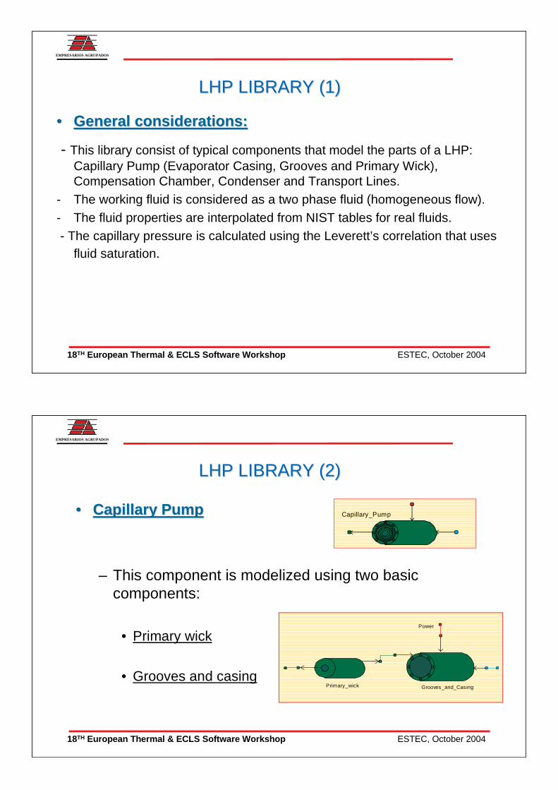
•• Capillary PumpCapillary Pump
– This component is modelized using two basic components:
• Primary wick
• Grooves and casing
Capillary_Pump
Grooves_and_Casing
Power
Primary_wick
ESTEC, October 200418TH European Thermal & ECLS Software Workshop
EMPRESARIOS AGRUPADOS
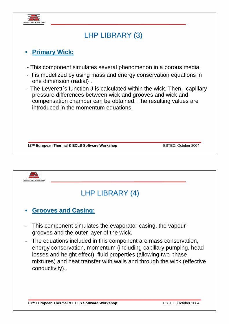
•• Primary Wick:Primary Wick:
-- This component simulates several phenomenon in a porous media.- It is modelized by using mass and energy conservation equations in
one dimension (radial) . - The Leverett´s function J is calculated within the wick. Then, capillary
pressure differences between wick and grooves and wick and compensation chamber can be obtained. The resulting values are introduced in the momentum equations.
LHP LIBRARY (3)LHP LIBRARY (3)
ESTEC, October 200418TH European Thermal & ECLS Software Workshop
EMPRESARIOS AGRUPADOS
•• Grooves and Casing:Grooves and Casing:
- This component simulates the evaporator casing, the vapour grooves and the outer layer of the wick.
-- The equations included in this component are mass conservation, energy conservation, momentum (including capillary pumping, headlosses and height effect), fluid properties (allowing two phase mixtures) and heat transfer with walls and through the wick (effective conductivity)..
LHP LIBRARY (4)LHP LIBRARY (4)
ESTEC, October 200418TH European Thermal & ECLS Software Workshop
EMPRESARIOS AGRUPADOS
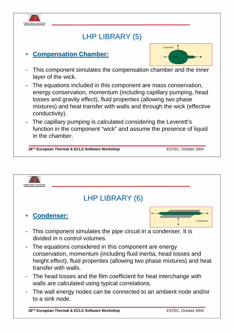
•• Compensation Chamber:Compensation Chamber:
- This component simulates the compensation chamber and the inner layer of the wick.
-- The equations included in this component are mass conservation, energy conservation, momentum (including capillary pumping, headlosses and gravity effect), fluid properties (allowing two phasemixtures) and heat transfer with walls and through the wick (effective conductivity).
-- The capillary pumping is calculated considering the Leverett’sfunction in the component “wick” and assume the presence of liquid in the chamber..
LHP LIBRARY (5)LHP LIBRARY (5)Cham ber
ESTEC, October 200418TH European Thermal & ECLS Software Workshop
EMPRESARIOS AGRUPADOS
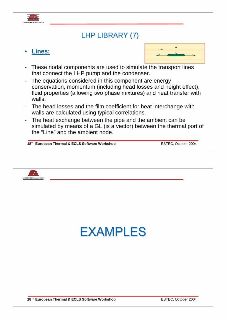
•• Condenser:Condenser:
-- This component simulates the pipe circuit in a condenser. It is divided in n control volumes..
-- The equations considered in this component are energy conservation, momentum (including fluid inertia, head losses andheight effect), fluid properties (allowing two phase mixtures) and heat transfer with walls.
- The head losses and the film coefficient for heat interchange with walls are calculated using typical correlations.
- The wall energy nodes can be connected to an ambient node and/orto a sink node.
LHP LIBRARY (6)LHP LIBRARY (6)
Condenser
ESTEC, October 200418TH European Thermal & ECLS Software Workshop
EMPRESARIOS AGRUPADOS
•• Lines:Lines:
-- These nodal components are used to simulate the transport lines that connect the LHP pump and the condenser. .
-- The equations considered in this component are energy conservation, momentum (including head losses and height effect), fluid properties (allowing two phase mixtures) and heat transfer with walls.
- The head losses and the film coefficient for heat interchange with walls are calculated using typical correlations.
- The heat exchange between the pipe and the ambient can be simulated by means of a GL (is a vector) between the thermal port of the “Line” and the ambient node.
LHP LIBRARY (7)LHP LIBRARY (7)
Line
ESTEC, October 200418TH European Thermal & ECLS Software Workshop
EMPRESARIOS AGRUPADOS
ESTEC, October 200418TH European Thermal & ECLS Software Workshop
EMPRESARIOS AGRUPADOS
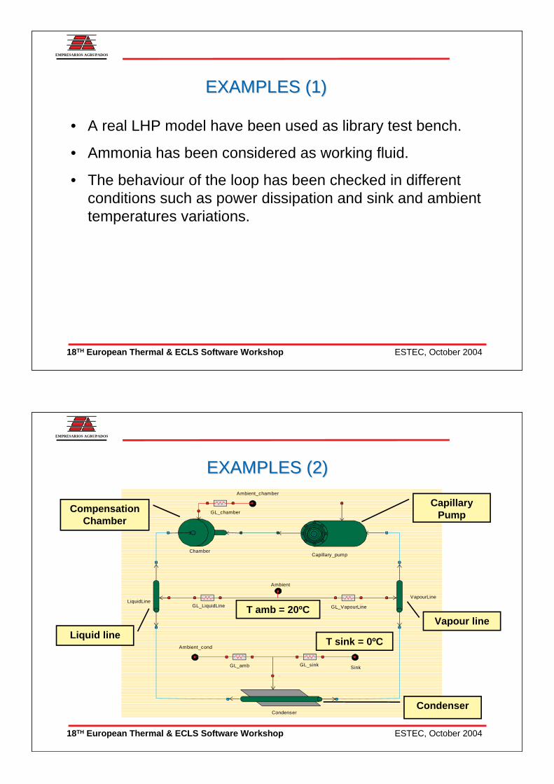
EXAMPLES (1)EXAMPLES (1)
• A real LHP model have been used as library test bench.
• Ammonia has been considered as working fluid.
• The behaviour of the loop has been checked in different conditions such as power dissipation and sink and ambient temperatures variations.
ESTEC, October 200418TH European Thermal & ECLS Software Workshop
EMPRESARIOS AGRUPADOS
EXAMPLES (2)EXAMPLES (2)
GL_sink Sink
Chamber
Condenser
LiquidLineVapourLine
GL_LiquidLine
Ambient
GL_VapourLine
GL_amb
Ambient_cond
Ambient_chamber
GL_chamber
Capillary_pump
CapillaryPump
Vapour line
Condenser
T sink = 0ºC
T amb = 20ºC
Liquid line
Compensation Chamber
ESTEC, October 200418TH European Thermal & ECLS Software Workshop
EMPRESARIOS AGRUPADOS
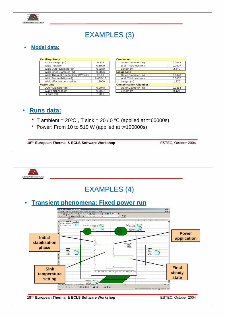
EXAMPLES (3)EXAMPLES (3)
•• Model data:Model data:
•• Runs data:Runs data:
* * T ambient = 20ºC , T sink = 20 / 0 ºC (applied at t=60000s)* * Power: From 10 to 510 W (applied at t=100000s)
Capillary Pump CondenserActive Length (m) 0.305 Outer Diameter (m) 0.0048W ick Porosity 0.6000 W all Thickness (m) 0.0007W ick Outer Diameter (m) 0.0239 Length (m) 2.540W ick Inner Diameter (m) 0.0076 Liquid L ineW ick Thermal Conductivity (W/m-K) 25.00 Outer Diameter (m) 0.0048W ick Permeability (m2) 6.45E-18 W all Thickness (m) 0.0007W ick effective pore radius 1.2000 Length (m) 1.270
Vapor L ine Compensation ChamberOuter Diameter (m) 0.0048 Outer Diameter (m) 0.0254W all Thickness (m) 0.0007 Length (m) 0.127Length (m) 1.016
ESTEC, October 200418TH European Thermal & ECLS Software Workshop
EMPRESARIOS AGRUPADOS
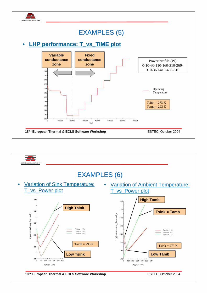
•• Transient phenomena: Fixed power runTransient phenomena: Fixed power run
EXAMPLES (4)EXAMPLES (4)
Power applicationInitial
stabilisation phase
Final steady state
Sink temperature
setting
ESTEC, October 200418TH European Thermal & ECLS Software Workshop
EMPRESARIOS AGRUPADOS
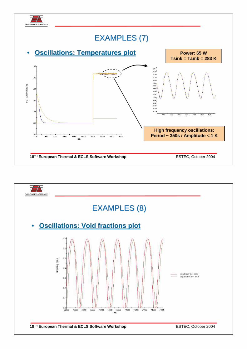
•• LHP performance: T_LHP performance: T_vsvs_TIME plot_TIME plot
EXAMPLES (5)EXAMPLES (5)
Variable conductance
zone
Fixed conductance
zone
OperatingTemperature
Power profile (W)0-10-60-110-160-210-260-
310-360-410-460-510
Tsink = 273 KTamb = 293 K
ESTEC, October 200418TH European Thermal & ECLS Software Workshop
EMPRESARIOS AGRUPADOS
EXAMPLES (6)EXAMPLES (6)•• Variation of Sink Temperature: Variation of Sink Temperature:
T_T_vsvs_Power plot_Power plot•• Variation of Ambient Temperature: Variation of Ambient Temperature:
T_T_vsvs_Power plot_Power plot
Operating T
emperature (K
)
Power (W)
Tsink = 273Tsink = 263Tsink = 283
High Tsink
Low Tsink Low Tamb
High Tamb
Tsink = Tamb
Tamb = 293 K Tsink = 273 K
Tamb = 293Tamb = 303Tamb = 273
Power (W)
Operating T
emperature (K
)
ESTEC, October 200418TH European Thermal & ECLS Software Workshop
EMPRESARIOS AGRUPADOS
•• Oscillations: Temperatures plotOscillations: Temperatures plot
EXAMPLES (7)EXAMPLES (7)
High frequency oscillations:Period ~ 350s / Amplitude < 1 K
Tem
perature(K
)
Power: 65 WTsink = Tamb = 283 K
ESTEC, October 200418TH European Thermal & ECLS Software Workshop
EMPRESARIOS AGRUPADOS
EXAMPLES (8)EXAMPLES (8)
•• Oscillations: Void fractions plotOscillations: Void fractions plot
Void fraction
Condenser last nodeLiquidLine first node
ESTEC, October 200418TH European Thermal & ECLS Software Workshop
EMPRESARIOS AGRUPADOS
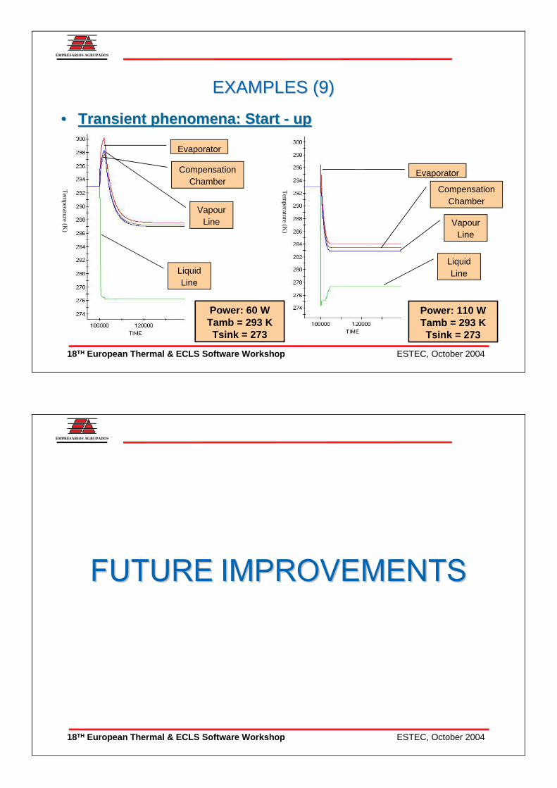
•• Transient phenomena: Start Transient phenomena: Start -- upup
EXAMPLES (9)EXAMPLES (9)
Evaporator
Power: 60 WTamb = 293 KTsink = 273
CompensationChamber
VapourLine
LiquidLine
Evaporator
CompensationChamber
VapourLine
LiquidLine
Power: 110 WTamb = 293 KTsink = 273
Tem
perature(K
)
Tem
perature(K
)
ESTEC, October 200418TH European Thermal & ECLS Software Workshop
EMPRESARIOS AGRUPADOS
ESTEC, October 200418TH European Thermal & ECLS Software Workshop
EMPRESARIOS AGRUPADOS
FUTURE IMPROVEMENTS FUTURE IMPROVEMENTS
• Implementation of the secondary loop to improve the determination of heat leak to catch the superheat precisely.
• To perform additional validation of the model
• Several nodes at the primary wick are already implemented to determine the fluid distribution. Some refinement are under development.
• To improve the correlations for two-phase flow.
• Friendly user interface.