Embed Size (px)
Citation preview


Contents
Introduction Needs Statement Objectives Statement Background Overview
Technical Additional Description Marketing Requirements Objective Tree
Table 1 Table 2 Figure 1 (Objective Tree Diagram)
Requirement Specification Table 3 Table 4 Table 5 Table 6
Alternate Features Design
Figure 2: Block Diagram of system. Figure 3: Detailed Block Diagram showing components.
Mechanical Construction Figure 4: Mechanical CAD drawing of the air intake and fan enclosure. Figure 5: Back view of enclosure showing air intake. Figure 6: Side view of enclosure. Figure 7: Dowel rods at the top of each tube.
Electrical Construction Figure 8: Basic electrical circuit for the switches and blowers. Figure 9: Four controllers with switched mounted. Figure 10: Board used for connections of blowers, switches, and resistors.
Design for 12 Volt AC to DC wall outlet power supply Description of concept Circuit Design
Figure 11: Power Supply Circuit Diagram Figure 12: Zener Diode Physics Explanation
Requirements and Specifications for power supply Figure 13: Blower Power Consumption at 12V Table 7: Power Supply Requirements
Circuit Simulation

Figure 14: Simulation Result Figure 15: Power Supply Overview Figure 16: Prototype and Design Comparison (1) Figure 17: Prototype and Design Comparison (2)
Alternate Designs Lab Instruction Documentation Analysis and Applicability of Constraints Standards and Regulatory Issues Single Tube Prototype
Figure 18: Single Tube prototype lifting pingpong ball Test Results
Project Management Milestones Task List Gantt Chart
Figure19: Gantt Chart (Red line represents today’s date) Required Resources
Table8: Cost of mechanical components used Table9: Cost of electrical components used Table10: Tools used to build the apparatus Table11: Total cost and budget Table12: cost for testing the apparatus
Risks Challenges, issues, and problems encountered
Conclusion

Introduction Needs Statement
In the meeting that our team held with Professor Passino, he mentioned that “...the current state of [electrical engineering] education in developing countries is governed by book-based learning”. This method, while beneficial in its own right, needs to be accompanied by a hands-on, lab based approach for best results. Professor Anderson, who operates and designs experiments that K-12 students from around Columbus use, quoted a lab cost of a couple hundred dollars as an arbitrary experiment cost. This cost is reasonable for areas that have people with the resources to support both methods. It proves difficult, however, in lower income areas because of the costs of running appropriate labs. There needs to be alternative lower-cost labs that can be performed to help in the education process of these areas. In order to help reduce this cost, and as a means to provide alternatives for the learning process in low income areas, we need to make a feedback control lab that can be built, transported, performed, and maintained cheaply.
Objectives Statement
The team will design and build a low-cost, hands-on engineering laboratory experience based
on a mechanical “juggler” that uses human as feedback control to manipulate ping pong balls inside
four tubes. The lab will teach students the concepts of open loop and closed loop feedback control as
well as team cooperation. Moreover the cost will be maintained under 85 U.S dollars as it will be
constructed from plastic and portable.
Background
The “Juggler” also referred to as the balls-in-tubes experiment was created to be an inexpensive
test experiment for dynamic resource allocation strategies that exploit information from the plant in
feedback. The dynamic resource allocation involves the limit on the amount of air the whole system
can use at a given time. The feedback involves the sensors used which will be mentioned later. There
exists a larger model of the “Juggler” in the Distributed Dynamical Systems Laboratory in Dreese labs.
The February 2005 issue of IEEE Control Systems Magazine, states the cost of this setup is around
$200 plus the cost of the power supply and wires. The system allows for the use of feedback to be
shown visually through the use of Devantech SRF04 ultrasonic sensors, Dynatron DF1209BB dc fans,
and a DS1104 dSPACE card. An issue faced with this system that we could also face would be the fact
that the time it takes for a ball to rise a fixed distance in a tube is generally greater than the time it takes
the ball to drop the same distance. Another issue would be if 4 tubes are used, the two in the center tend
to have greater airflow due to the input manifold being in the center of the model. Our group aims to
recreate this setup in a cheaper form. This will be achieved by using human feedback instead of the
sensors. The dynamic resource allocation strategies through juggling or balancing the balls forcing the
users to cooperate with each other to complete the objective will still be implemented.
The purpose of the ‘Juggler Lab’ is to make sure students have interactive exposure to how
electrical apparatus can teach you physical principles. The lab is designed in a manner to make the
students understand feedback as well as cooperation. The lab aims to target these concepts by allowing
the students themselves to be the feedback. This is achieved with the task of trying to balance the
Ping-Pong ball at a certain height. The switches play as mode to allow the students to use their
feedback response. Another concept the ‘Juggler Lab’ teaches students is to act and perform the
experiment as a team. This is incorporated by having 4 switches with 4 different people controlling
them and the aim is to try and balance the balls at a specific height level while cooperating with other
users of the apparatus. This makes the lab fun as well as intuitive.
Overview
The remainder of this document will give in detail the specifications and requirements that the
juggler was designed to meet. Following this, we will present our final design as well as the iterations
that we went through. Next, a report is given of testing and results showing how the design met the
desired specifications. Finally, some project management considerations will be given such as design
and implementation costs and issues faced.

Technical Additional Description
A major factor in engineering is teamwork. The lab is designed to help with working
together as a unit. This will be achieved through three factors of the lab: 1) Personal tasks, 2) The
bigger picture and 3) Communication.
On a team, each member has a job that they need to perform. For the juggler, each
student must balance a ball in a given region. This mirrors the concept sufficiently.
The second factor that must be realized is the big picture. Since the airflow into the device is
finite, how an individual ball performs is dependent on the other tubes. It is designed to simulate
the need for cooperation.
Cooperation leads to communication. For a team to succeed a channel of communication
must be opened. This will hopefully be a way to show the collaborative nature of engineering
work.
Marketing Requirements
1. The lab should be designed on a low cost budget.
2. The apparatus should be light-weight.
3. The apparatus should be compact to fit easily on a lab bench.
4. The product should be interactive.
5. The product must be challenging for the students to perform.
6. The lab should be usable in a reasonable classroom.
7. Easy manual and instruction set should be provided for the lab such that it can be
understood in any country across the globe.
The proposed requirements are to be able to market the product as a WeLab. The purposes of
these labs are to make electrical engineering more accessible. This is especially true in under
developed countries. The lab should be low-cost. The lab is to be marketed as portable. The
set-up should be light weight and useable in a reasonable classroom. Last the lab will be
moderately fun. This is taken as interactive and challenging. A breakdown of these requirements
is provided in the objective tree section.
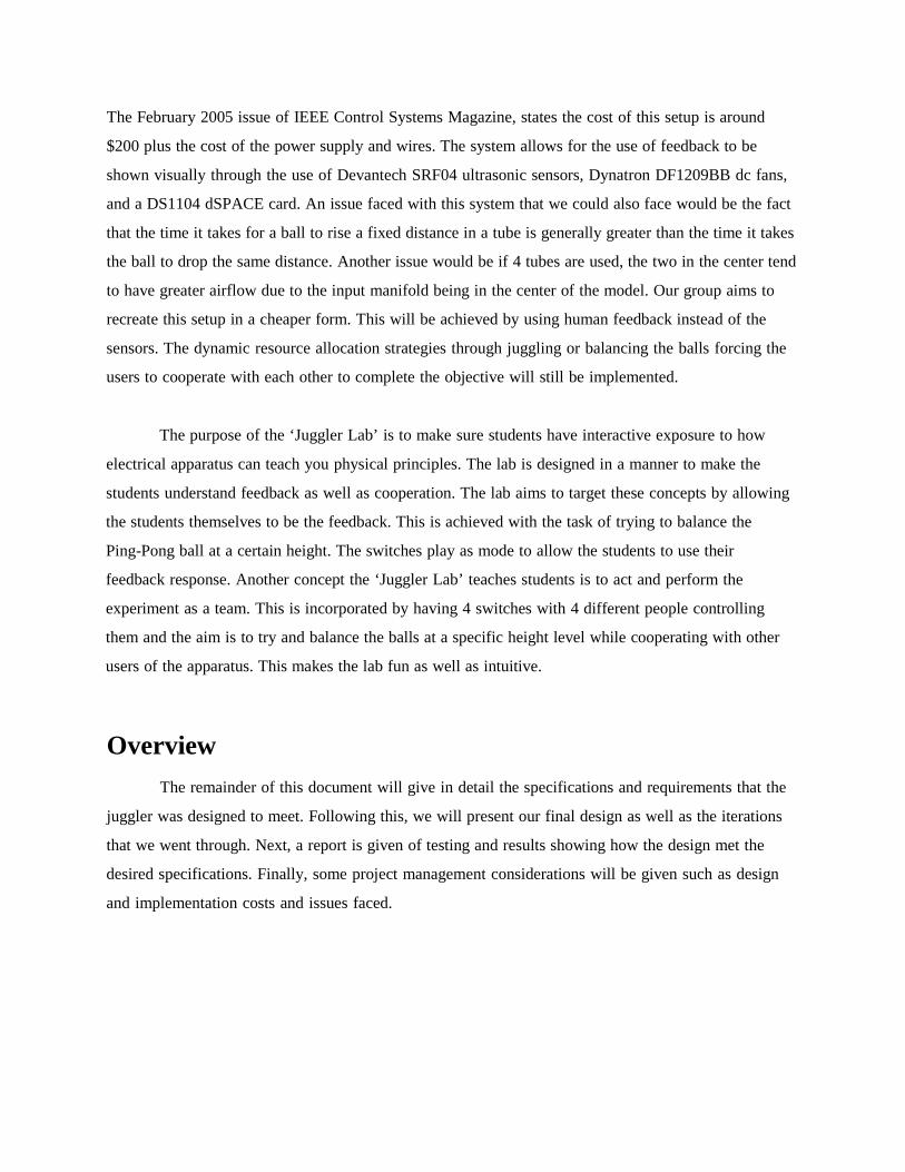
Table 1 shows how the group weighted each of these goals in reference to the final product. The
main conflicting goals were between cost, interactivity, and challenge. Challenge was weighted
as the most important at 65%. Interactivity and cost of production followed at 25 and 11 percent
respectively. The items in table 2 were independent from those in table 1. Ease of manual is the
most important here.
Objective Tree
Table 1
Low-Cost Interactive Challenging GMean Weight
Low-Cost 1 .333 .20 0.41 0.11
Interactive 3 1 .333 1.0 0.25
Challenging 5 3 1 2.46 0.64
Table 2
Advanced application Easy manual GMean Weight
Advanced application 1 0.25 0.5 0.2
Easy manual 4 1 2 0.8

Figure 1 (Objective Tree Diagram)
Requirement Specification Table 3
Engineering Requirements
Marketing
Requirements
Engineering
Requirements
Justification
1 Total cost < $85 Developing countries may not have much money
for lab equipment

1, 4, 5, 7 Controls with < 6
buttons
To keep the use simple and interactive there
should be a controller with minimal buttons
1, 2 Total weight < 50
lbs.
Flights out of the country have a baggage weight
limit of 50 pounds to keep from getting extra
fees (1).
3, 6 Fit within a 1x1x1
meter box
To keep the size manageable for a lab bench
6, 4, 7 Manual with
pictures
To keep the manual simple as well as getting the
point across
2 Use of a 12V
batteries
To provide easy replacement of batteries.
Batteries readily available in the respective
country.
Table 3 shows the requirements that were designed to meet. The price was kept under $85. This
ideally would have been under $50. Due to some changes in design however the baseline price
was increased. The other big change was the use of 12V batteries. A self-produced power supply
was used instead. The implementation will still be functional with a battery source. The other
requirements have not changed.

Table 4
Table 5

Table 6
Tables 4, 5 and figure 6 show the feasibility analysis of the project. The house diagram in figure
6 wraps up the goals and how well they would work together. The positive 1’s show goals that
can be performed simultaneously, negative 1’s are conflicting. It shows cost, total weight and
total size all can be improved at once. It is interesting to note that reducing the number of buttons
also reduces interactivity. Also, if the manual is too easy, then challenge is adversely affected.
An easy manual is one that gives students the exact procedure to balance the balls.
Alternate Features
There were many possible features the team investigated. From electrical to mechanical
options some we rejected immediately and others we tested and chose the best route based on our
results. In terms of the electrical design we sketched up many different designs the for features
we wanted. We contemplated adding an electrical feedback system incorporating sensors at the
top of each tube similar to the original “Juggler”. This system would utilize a microcontroller to
control each sensor. The team rejected this idea early due to the fact that we wanted the system
to be interactive for the users and this was accomplished through the users being the mode for
feedback which will be explained later. The group also investigated adding color L.E.D. to mark

each tube with a different color and the same color to mark each controller. This was rejected
because it was easier to just number each tube and their corresponding controller. Another
electrical feature of the system the group investigated involved adding a momentary switch
instead of the normal flip switches. We rejected this in the beginning because we thought we
would need a 3 state switch for high/low/off but ended up only using high and low power. In
light of this using a momentary switch would have been a better option after testing. If the group
had more time to work on the project we would have experimented with implementing this type
of switch.
As for the mechanical features, due to the fact that our design was based off a previously
designed lab, the design of our apparatus was straightforward and therefore did not involve any
extra features.
Design
The main concept that fueled the design of our teams project was feedback. The interaction of
the user allows the juggling to occur. Figure 2 below details how the user input to the system
affects the apparatus. Figure 3 below is a more detailed block diagram of the system showing the
major components.

Figure 2: Block Diagram of system.
Figure 3: Detailed Block Diagram showing components.
Mechanical Construction
The air intake and the enclosure that houses the fans was constructed with plexiglass and the
CAD drawing displaying the measurements is shown below in Figure 4. We were aided in the
cutting of the plexiglass by Mr. Thalgott in the basement shop. Once we acquired the needed

pieced we assembled the structure using PVC glue. The completed enclosure is shown below
with fans inside in Figures 5 and 6.

Figure 4: Mechanical CAD drawing of the air intake and fan enclosure.
Figure 5: Back view of enclosure showing air intake.
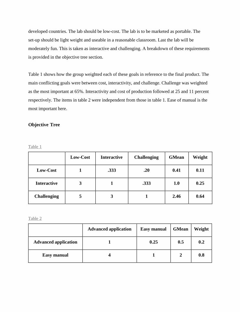
Figure 6: Side view of enclosure. The next step in the construction process was to attach the 4 tubes to the base which is also
shown completed in Figures 5 and 6. Figure 7 display the tops of each tube. The team glued
dowel rods on the bottom of each lid for the tubes. This prevents the ping pong balls from getting
stuck in the tops of the tubes which was a problem we ran into.
Figure 7: Dowel rods at the top of each tube.
Electrical Construction
The electrical construction involved the basic circuit below in Figure 8. The components were
four blowers, four switches for low and high power mode, and four 50 ohm resistors. The
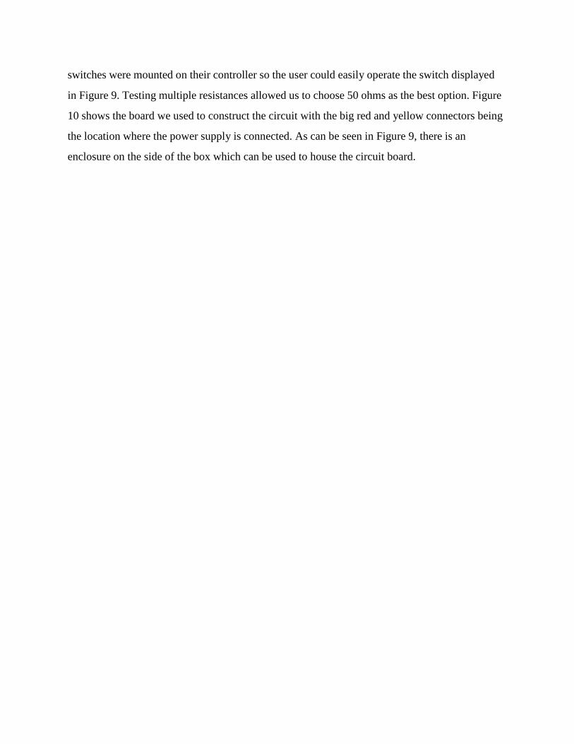
switches were mounted on their controller so the user could easily operate the switch displayed
in Figure 9. Testing multiple resistances allowed us to choose 50 ohms as the best option. Figure
10 shows the board we used to construct the circuit with the big red and yellow connectors being
the location where the power supply is connected. As can be seen in Figure 9, there is an
enclosure on the side of the box which can be used to house the circuit board.

Figure 8: Basic electrical circuit for the switches and blowers.

Figure 9: Four controllers with switched mounted.
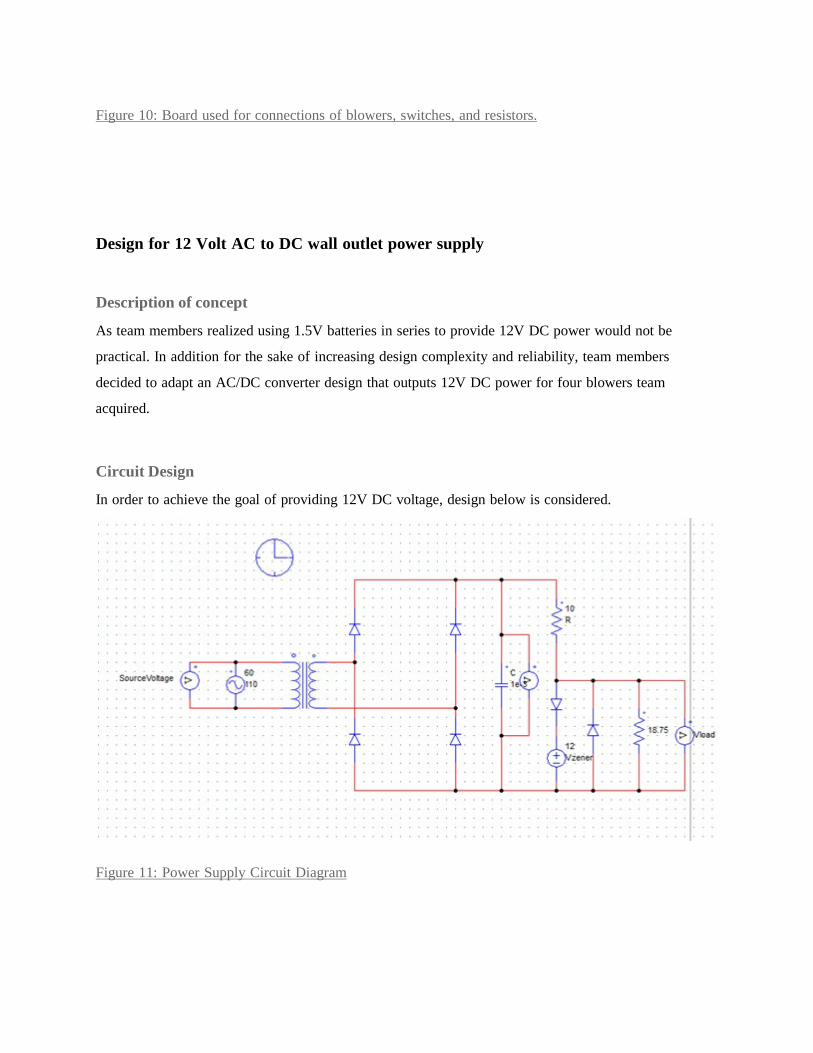
Figure 10: Board used for connections of blowers, switches, and resistors.
Design for 12 Volt AC to DC wall outlet power supply Description of concept
As team members realized using 1.5V batteries in series to provide 12V DC power would not be
practical. In addition for the sake of increasing design complexity and reliability, team members
decided to adapt an AC/DC converter design that outputs 12V DC power for four blowers team
acquired.
Circuit Design
In order to achieve the goal of providing 12V DC voltage, design below is considered.
Figure 11: Power Supply Circuit Diagram

The ultimate goal of the power supply is to provide 12V DC voltage for the sub circuit of the design.
To accomplish our goal we first use a transformer to stepdown AC voltage from 110V to roughly 30V.
Follow by Diode Bridge, negative voltage cycle will be folded to positive region. After adding a
capacitor, Voltage ripple will be smoothed out dramatically. At last a 12V Zener diode regulator design
will be utilized in order to achieve a 12V DC output.
A Zener diode is a diode which allows current to flow in the forward direction in the same manner as
an ideal diode, but also permits it to flow in the reverse direction when the voltage is above a certain
value known as the breakdown voltage. When operating at reverse bias, voltage across diode will be
12V. Figure below explains the physics of Zener Diode.
Figure 12: Zener Diode Physics Explanation
Requirements and Specifications for power supply
Since the purpose of the power supply is to provide reliable power source for four blowers solely to lift
ping pong balls, the power supply is required being able to output 12V DC voltage. In addition, as
tested in the lab each fan will consumed 0.17A current at 12V (shown below). Therefore, the power
supply will also be able to provide a minimum current at 0.68A.

Figure 13: Blower Power Consumption at 12V
Engineering requirements Justification
Power Supply
Output 12V DC &
Minimum 0.68A
0.68A is the nominal current consumption of all
four fans and 12V is fan's operating voltage
Capacitor
Being able to handle up to
36V
Transformer outputs 36V Voltage
Pull up resistor
20ohms & being able to
handle up to 6.8W
All current will flow through the pull up resistor.
W=I*R=0.68A*10ohms=6.8W
Zener Diode
Being able to handle up to
0.68A
Nominal current flowing through will be 0.68A

Table 7: Power Supply Requirements Circuit Simulation
Before construction team member ran software simulations for the sake of circuit reliability and being
able to fully understand the circuit. Below is the simulation result.
Figure 14: Simulation Result
Red line presented in the graph represents input AC voltage. Voltage across capacitor is being
presented by blue line. At last, green line is the output voltage of the power supply

Figure 15: Power Supply Overview

Figure 16: Prototype and Design Comparison (1)
Figure 17: Prototype and Design Comparison (2)
Alternate Designs
Throughout the design of our project the team ran into many problem we had to work though in
order to get to our final successful design. The first problem we ran into was both mechanical
and electrical. The team had difficulty implementing our initial design for the prototype and
successfully lifting the ping pong ball. This was due to the fact that the first set of fans we
purchased were 4.7” in length and we used a pyramid design for the base. Due to both the
mechanical design of the base and the size of the fan, there was not enough force at the bottom of
the tube to lift the ball. The team realized we needed to reject both the large computer fans and
the pyramid base design. The teams solution to this problem was to change from using a
computer fan to a blowers. We got our idea to experiment with a blower from research on the
internet. The blower was a positive addition to our apparatus because it applied its entire output
force at the base of the tube so lifting the ball was much easier. Additionally it was much smaller
in size than the previous fans, so this allowed for a much smaller rectangular design for our base.
This made it much more structurally sound by decreasing the overall size of the base and gluing

together a rectangular box was much easier than the previous pyramid design. In addition the
change made the apparatus cheaper which was a requirement of our project. The second problem
was the fact that our choice of power for the system was not sufficient for the force we needed to
come out of the fans. After testing the eight D batteries, which was our original idea, the team
decided to build the power supply mentioned above and this was a much better solution than the
batteries. First because is supplied then additional power needed to keep the balls lifted and
second it was a reusable source that did not need to be replaced like the batteries.
Lab Instruction Documentation
The WeLab will also come with instructions similar to those given in a class period. The
proposed lab procedure is defined in a stand alone document that is included with the lab. The
purpose is to allow them to be posted separately from the machine itself. This will allow the most
people to view and use the product.
Structurally the instructions are divided into two parts: A teacher’s manual, and a student
version. The teachers manual outlines the purpose of the lab. It will give what concepts are being
taught and how. Additionally, the teacher version contains a parts list as well as details on
constructing a juggler. This is to allow multiple people to build a cost effective lab. Finally the
teacher version will give several troubleshooting tips. The student portion gives a walkthrough
on how to perform the lab.
Analysis and Applicability of Constraints
Economical: The lab is designed to be less than $80 to provide a cheap, but also provide an
intuitive lab experience for students in developing countries. This economical lab explains the
different concepts by providing the students with hands-on experience.
Environmental: The materials used for the lab are environment safe. The tubes are made from
recyclable plastic. The ping pong balls are also biodegradable and can be disposed of easily

without harming the environment. The case that is used to enclose the apparatus is made out of
plexiglass and is a material that are also biodegradable. The power supply is the only part of the
apparatus that could harm the environment if disposed of incorrectly.
Social: The lab is designed in a way to provide a very social experience to all the users that
perform the lab. The users have to communicate with each other in an interactive manner to
balance the Ping-Pong balls inside the tubes. The users each have access to each of the switches
on the apparatus that controls the fan in each of the tube. Thus, this lab provides a really social
and team based experience which helps the students learn more about team coordination and
communication skills.
Health and safety: Since the lab is targeted to the students the health and safety has been the
number one priority in designing the lab. The tubes are made up of plastic instead of using glass
to make sure no one gets injured in case the apparatus was to break. The wires and the circuitry
of the apparatus are not easily accessible to ensure none of the students get injured by a shock.
The apparatus is designed in a way such that it has a lower center of gravity and thus making it
hard for it to topple over and hurting some students’ foot.
Sustainability: The tubes and the fans in the apparatus are designed and placed in a way such that
they are easily replaceable in case they go defective. The ping pong balls can also be replaced
easily. In addition the power supply should last a very long time are the parts are rated for long
term use.
Standards and Regulatory Issues
Safety standard: Occupational Safety and Health Standards-1910.304(f) Power Supply Standard: IEC/TS 62700 Ed. 1.0 en:2014

IEC TS 62700:2014(E) states the minimum requirements for DC power supply for notebook
computers. Specifically, it gives an electrical specification (performance characteristics), an ID
pin method and a connector for DC power output.
Lab standard: IEC 61010-1 / IEC 61326-1
The IEC 61010-1 / IEC 61326-1 - Electrical Equipment Package provides safety and EMC
requirements for electrical equipment in a laboratory setting. It also provides general
requirements for electrical test and measurement equipment, electrical industrial process-control
equipment and electrical laboratory equipment. The IEC 61010-1 / IEC 61326-1 - Electrical
Equipment Package includes:
IEC 61010-1 Ed. 3.0 b:2010
IEC 61326-1 Ed. 2.0 b:2012 All designs team used will follow standards listed above to comply our safety and voltage supply
requirement.
Single Tube Prototype
Our prototype although successful, opened our eyes to a lot of issues our system had that through
changes allowed us to have a better final product. The ultimate goal of our single-tube prototype
was to successfully lift the pingpong ball. We accomplished this and our prototype is shown in
Figure 10 below lifting the ball. Our prototype was built using the larger fans mentioned earlier
that were later replaced with blowers. This is when the team first realized that a smaller solution
was needed. In addition the base for the tube and enclosure for the fan was constructed in a
pyramid design out of plexiglass, which was very hard to construct and keep stable. This was
mentioned earlier when talking about changes the team made in design. The use of blowers
allowed for a square base. With our prototype we also tested the use of eight D batteries and this

also failed so we ended up using a power supply in the lab for the prototype and decided to build
our own for the final system.
Figure 18: Single Tube prototype lifting pingpong ball

Test Results
During the time of building this lab design, the team encountered many problems. To make sure the
design can run correctly, the team did following tests and experiments.
1. Power Supply:
The team planned to use D-batteries as the power supply before the team decided to use blowers
instead of regular computer fans. But after the testing, the D-batteries did not give the computer fans
enough power to lift the ping pong balls. So the team decided to use the in-wall power supply. Since
voltage from the in-wall power supply is 110V, the team also design a AC-DC step-down converter
circuit. After testing, the team converted the 110V AC voltage into a 12V DC voltage.
2. Fan Experiment:
When the team built the single tube prototype, the regular computer fans did not work very well.
They did not have enough concentrated strength to lift the balls under the 12V DC voltage. Instead of
using the regular computer fans, the team decided to use the more powerful blowers. The blowers can
easily lift the balls under 12V DC voltage.
3. Resistor Experiment:
In order to create the low power settings, which makes the balls drop very slow, the team did the
voltage experiment first and found the acceptable voltage range for the design was between 6.5V to
7.5V. After series of calculations, the team found the demand resistance - 50Ω. In case the resistor
might burn, the team decided to use a 50Ω resistor with a higher rating.
4. Single Tube Prototype Experiment
After all the above experiments, the team decided to put all the parts together and make a single
tube prototype. The purpose of this experiment is to test whether each part of this design can work well
together. During this experiment, the design easily lifted the ping pong balls. Under the low power
setting the ping pong ball can drop down very slow. So single tube prototype work pretty well.
5. Final testing
Based on the single tube prototype, the team built the final design. In the final design, there are
four tubes and four blowers, and each of them has the high mode and low mode. They are constructed
in parallel as the team planned. Before the team sealed all the pieces of the design, the team did the

final testing. Before turning on the master switch, all the blowers were set to default mode, which is
high mode. After turning on the master switch, all the ping pong balls were successfully lifted up and
hit the top. The the team tested the low mode for each blower, and they all worked correctly. Under the
low mode, all the ping pong balls drop down very slow. So the final testing was very successful.
Project Management Milestones To keep the project organized and finish it in a timely order. These milestones were chosen:
1. Completing the electrical blueprint for four multiple speed fans.
2. Prototype for a single tube completed. To make sure hardware setup is feasible
3. Full system prototype completed. This will be the finished product completion Task List Each of the milestones had tasks and subtasks under it.
1) Electrical Power Distribution Circuit
a) Design
i) Layout
ii) Calculations
b) Purchase Components
i) List
ii) Place the order
c) Construct/Test
2) Single Tube Prototype
a) Mechanical Design/Construction
b) Electrical Construction For Single Tube
c) Testing
3) Full System Prototype
a) Construction
i) Electrical

ii) Mechanical
iii) Air-manifold
b) Testing
i) Safety
ii) Stability
iii) Performance Gantt Chart

Figure19: Gantt Chart (Red line represents today’s date) Required Resources
Mechanical Construction
Item Price
Plexi Glass $8.32
Tubes $5.00
4, Pingpong Balls $1.00 ea.
Glue Varies (According to use)
4, Blowers $8.56 ea.
4, Nuts and Screws: $0.25 ea
Electrical Components
Table8: Cost of mechanical components used
Item Price
5, Switches $1.00 ea.
Bridge-Diode $0.62 ea.
12 Volt Zeiner Diode $0.54
Step-Down Transformer $11.37
2, 20-Ohm Resistors $0.64 ea.
4, 50 ohm Resistor $1.72 ea.
50 Volt Capacitor $0.90
Power Adapter Varies (Any power adapter works)

Table9: Cost of electrical components used Tools
Item
Sodder
Multimeter
Wire-cutters/Wire-strippers
Band-saw
6, Circuit Boards
Wire to connect
Table10: Tools used to build the apparatus
Total cost of apparatus $79.15
Requirement cost estimation $85.00 (We Lab)
Total Budget for the project $500.00
Table11: Total cost and budget Cost for testing(not used in the final apparatus):
Item Price
Boost, Flyback, SEPIC and Inverting Controller $4.40
40V N-Channel MOSFET $0.22
12, D-batteries $8.39
4, computer super quiet Fans $5.00 ea
4, computer fans $2.38 ea.
Plexiglass $2.45

tubes $2.50
2, 20 Volt Zeiner diode $0.54 ea.
Table12: cost for testing the apparatus
Risks
1. Durability: Since the apparatus is going to be used by students, the apparatus must be
durable. The team faced several design problems to make the apparatus durable and
reusable by the students. One of the key design changes that the team used to resolve this
issue was to have a separate panel for the implementation of the switches. This would not
only allow easy access to the switches but will also refrain the students from touching the
circuit board.
2. Resistor getting hot: The power going through the resistor was very high. This caused
the resistor to become very hot. Since the apparatus had to be safe to use the team had to
tackle this problem and make it safe to use. Thus, the team decided to add another
20-ohm resistor in parallel. This reduced the load on each of the resistor and thereby
made them less hot.
3. The diode: During testing the final apparatus, the team realized that the diode being used
is of low rating. This meant that it is not capable of allowing or handling a lot of power.
The team decided that the problem wasn't very severe and need not be resolved.
Challenges, issues, and problems encountered
The semester went as well as one might expect. We feel like our intended goal was met.
There were, however, several issues that came up. The issues ranged from circuit problems to
construction issues.
The circuit challenges were fairly few. The first issue encountered was determining the
resistance values for LOW power mode. This was determined through performance testing and
was resolved. The next distinct problem we faced was complexity. This design is culminating
from our collegiate experience. The original circuit that was proposed was too trivial. This was a

problem because it didn’t show what was learned through school. To combat this, the group
produced a working power supply to accompany the juggler. Adding the power supply gave rise
to a final issue. Some components initially had too much power going across them. To resolve
this two methods were employed. The first was to order better rated components. The second
was to put devices in parallel to reduce the current flow through an individual device.
All the construction issues were due to the fact that our group was all electrical engineers.
Actual physical system tasks were not as practiced as the electrical ones. The first issue was how
to actually build the parts. This was resolved thanks to Mr. Thalgott who machined all of our
pieces. In the talks with Thalgott, it was discovered that some dimensions on the initial design
were off. He helped us rectify this.
Once everything was cut the group had to construct the final prototype. We did not want
to drill any holes in the plexiglass. The risk of breaking a piece was too high. To combat this, we
screwed the blowers directly together instead of attaching them to a wall. The result was the
same. We then used the pieces for stabilizing the tubes.
Conclusion
To conclude, the team builds an apparatus called ‘the juggler’ that helps schools in
developing countries to have inexpensive interactive labs. ‘The juggler’ is an apparatus that uses
human as feedback control to manipulate ping pongs balls inside tubes. The lab will teach
students about the concepts of open loop and close loop feedback control as well as team
cooperation. The apparatus also teaches the students a handful of different concepts that help
them develop skills like problem solving, communication, co-ordination with the team members,
etc. The project is designed to be economical, safe for students, intuitive, social, sustainable and
environmentally safe. This is achieved by using different design techniques to build the juggler.
The problem that developing countries currently have is that they cannot afford to conduct
labs that are intuitive enough to make the students understand abstract concepts by providing
students with a hands on experience on these abstract concepts. The labs are generally really

expensive and thus, the school decides not to hold labs for the students. This makes it harder for
students to understand the concepts. The solution that the team provides is an affordable
apparatus that is sustainable and can be used multiple times in a year. The apparatus called the
juggler provides the schools a lab and benefits the students to learn and understand the different
concepts that the apparatus teaches.
This experience of the juggler can be enhanced in a lot of ways. Firstly, the juggler’s
control feedback mechanism can completely be completely automated. This would be achieved
by adding laser sensors on the top of each of the tubes to find out the level at which the
Ping-Pong ball is floating. These sensors can in turn send data to a microcontroller that controls
the speed of the fan and thereby keeping all four balls at the same level. The second enhancement
that can be done on this apparatus is, by adding Ping-Pong balls of different weights. This
makes it more challenging for the students to maintain the balls at the same level. Another
enhancement that can be done in this apparatus is to have different strength fans. This has the
same benefits as the previous enhancement and causes more communication and coordination
among the users who serve as a control mechanism for the apparatus.
Overall, this project includes many techniques, some of them are what we have learned
from classes, and some of them are from online resources. During the time of building this
design, every team member learned how to cooperate as a team. Although, sometimes team
members had some disagreements about some problem, we could always find the best solution.
From this project, the team gained experience about how to finish a real life project as a
professional engineer. The team also learned the most valuable lesson about how to work as a
team.