Embed Size (px)
Citation preview

Title Section
GENERAL INFORMATION 00
BODYSTRUCTURE
CONSTRUCTION 80A
PANEL REPLACEMENT 80B
WATER-PROOF AND RUST PREVENTIVE 80C
DIMENSIONS 80D
PLASTIC BODY PARTS 80E
CONTENTS2007Mazda MX-5BodyshopManual
FOREWORD
This bodyshop manual is intended for use by technicians of Authorized Mazda Dealers to help them service and repair Mazda vehicles. It can also be useful to owners and operators of Mazda vehicles in performing limited repair and maintenance on Mazda vehicles.
For proper repair and maintenance, a thorough familiarization with this manual is important, and it should always be kept in a handy place for quick and easy reference.
All the contents of this manual, including drawings and specifications, are the latest available at the time of printing.As modifications affecting repair or maintenance occur, relevant information supplementary to this volume will be made available at Mazda dealers. This manual should be kept up-to-date.
Mazda Motor Corporation reserves the right to alter the specifications and contents of this manual without obligation or advance notice.
All rights reserved. No part of this book may be reproduced or used in any form or by any means, electronic or mechanical including photocopying and recording and the use of any kind of information storage and retrieval system-without permission in writing.
Mazda Motor CorporationHIROSHIMA, JAPAN
APPLICATION:This manual is applicable to vehicles beginningwith the Vehicle Identification Numbers (VIN),shown on the following page.
© 2006 Mazda Motor CorporationPRINTED IN U.S.A., JUNE 2006Form No. 3426–1U–06FPart No. 9999–95–060F–07
3426-1U-06F(INDEX).fm 1 ページ 2006年6月20日 火曜日 午後3時43分
VEHICLE IDENTIFICATION NUMBERS (VIN)
JM1 NC15F✻7# 100001—JM1 NC16F✻7# 100001—JM1 NC25F✻7# 100001—JM1 NC26F✻7# 100001—
3426-1U-06F(INDEX).fm 2 ページ 2006年6月20日 火曜日 午後3時43分
00GENERAL INFORMATION
00-00–1
SECTION00-00
Toc of SCTGENERAL INFORMATION . . . .00-00
Toc of SCT
00-00 GENERAL INFORMATIONVEHICLE IDENTIFICATION NUMBER
(VIN) CODE . . . . . . . . . . . . . . . . . . . . . . 00-00–2VEHICLE IDENTIFICATION NUMBER
(VIN) . . . . . . . . . . . . . . . . . . . . . . . . . . . . 00-00–2HOW TO USE THIS MANUAL . . . . . . . . . 00-00–3
Efficient Replacement of Body Panels . . . . . . . . . . . . . . . . . . . . 00-00–3
Symbols of Panel Replacement . . . . . . 00-00–4Body Dimensions
(Flat-plane Dimensions) . . . . . . . . . . . 00-00–4Body Dimensions
(Straight-line Dimensions). . . . . . . . . . 00-00–6Symbols of Body Dimensions . . . . . . . . 00-00–8
SERVICE PRECAUTIONS . . . . . . . . . . . . 00-00–8Arrangement of Workshop . . . . . . . . . . 00-00–8Safety Precautions . . . . . . . . . . . . . . . . 00-00–8Vehicle Protection . . . . . . . . . . . . . . . . . 00-00–8Remove Dangerous Articles . . . . . . . . . 00-00–9Use of Pulling Equipment . . . . . . . . . . . 00-00–9Prevent Short Circuits . . . . . . . . . . . . . . 00-00–9
EFFICIENT REMOVAL OF BODY PANELS . . . . . . . . . . . . . . . . . . . . . . . . . 00-00–10
Body Measurements . . . . . . . . . . . . . . . 00-00–10Prevention of Body Deformation . . . . . . 00-00–10
Selection of Cut-and-join Locations . . . . . . . . . . . . . . . . . . . . . . 00-00–10
Removal of Associated Parts . . . . . . . . 00-00–10Rough Cutting of Damaged Panel . . . . 00-00–11
INSTALLATION PREPARATIONS. . . . . . 00-00–11Rough Cutting of New Parts. . . . . . . . . 00-00–11Determination of Welding
Method . . . . . . . . . . . . . . . . . . . . . . . . 00-00–11Making Holes for CO2 Arc
Welding . . . . . . . . . . . . . . . . . . . . . . . 00-00–12Application of Weld-through
Primer. . . . . . . . . . . . . . . . . . . . . . . . . 00-00–12EFFICIENT INSTALLATION OF
BODY PANELS . . . . . . . . . . . . . . . . . . . 00-00–12Checking Preweld Measurements And
Watching . . . . . . . . . . . . . . . . . . . . . . 00-00–12Welding Notes . . . . . . . . . . . . . . . . . . . 00-00–13Spot Welding Notes . . . . . . . . . . . . . . . 00-00–13Checking Weld Strength. . . . . . . . . . . . 00-00–14
ANTICORROSION, SOUND INSULATION, AND VIBRATION INSULATION . . . . . . . . . . . 00-00–15
Body Sealing . . . . . . . . . . . . . . . . . . . . 00-00–15Application of Undercoating . . . . . . . . . 00-00–15Application of Rust Inhibitor . . . . . . . . . 00-00–15Application of Damping Sheet . . . . . . . 00-00–16
ABBREVIATION . . . . . . . . . . . . . . . . . . . 00-00–16
End of TocNG: GENERAL INFORMATION
3426-1U-06F(00-00).fm 1 ページ 2006年6月20日 火曜日 午後3時36分
GENERAL INFORMATION
00-00–2
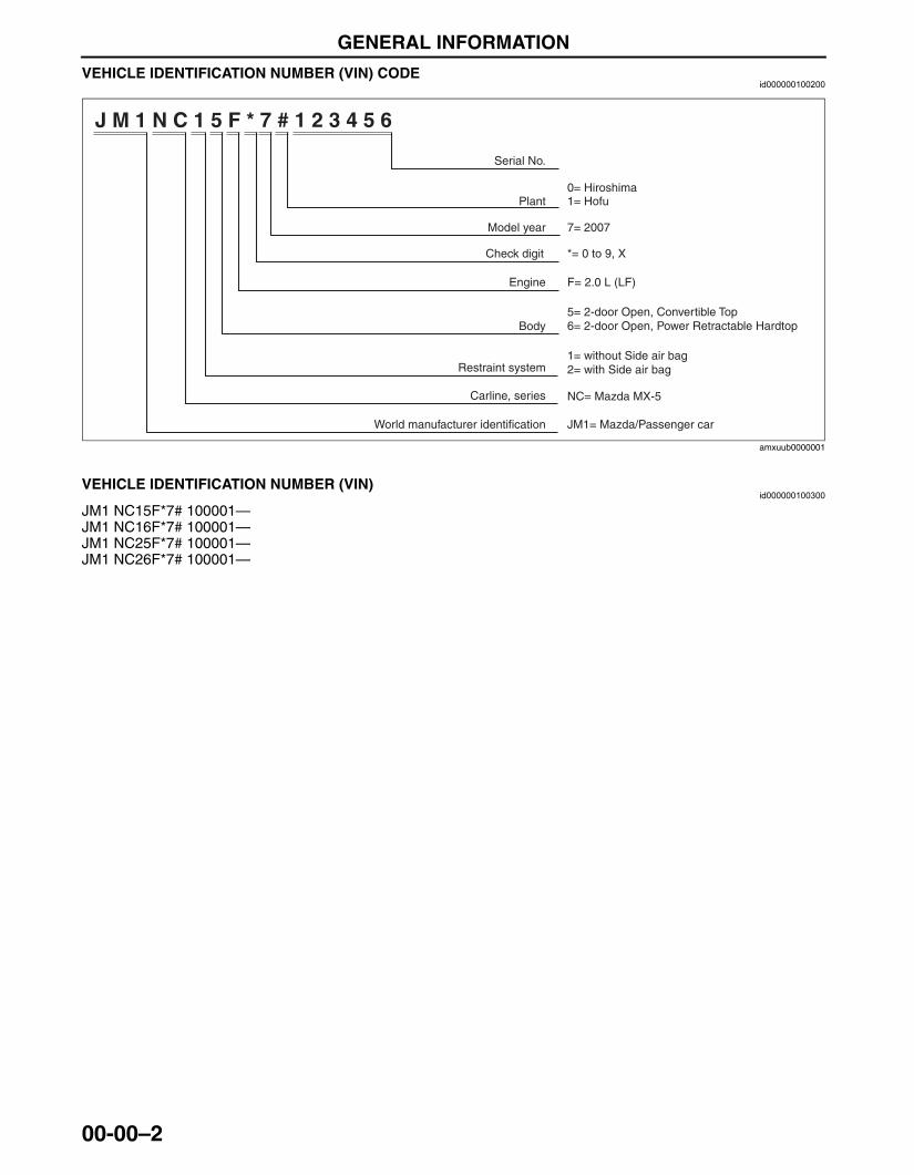
VEHICLE IDENTIFICATION NUMBER (VIN) CODEid000000100200
End Of SieVEHICLE IDENTIFICATION NUMBER (VIN)
id000000100300
JM1 NC15F*7# 100001—JM1 NC16F*7# 100001—JM1 NC25F*7# 100001—JM1 NC26F*7# 100001—End Of SieBM: GENERAL INFORMATION
J M 1 N C 1 5 F * 7 # 1 2 3 4 5 6
Serial No.
0= Hiroshima
JM1= Mazda/Passenger car
*= 0 to 9, X
Plant
Check digit
Restraint system
Body
Carline, series
1= Hofu
Model year
Engine F= 2.0 L (LF)
NC= Mazda MX-5
World manufacturer identification
5= 2-door Open, Convertible Top6= 2-door Open, Power Retractable Hardtop
7= 2007
1= without Side air bag2= with Side air bag
amxuub0000001
3426-1U-06F(00-00).fm 2 ページ 2006年6月20日 火曜日 午後3時36分
GENERAL INFORMATION
00-00–3
00-00
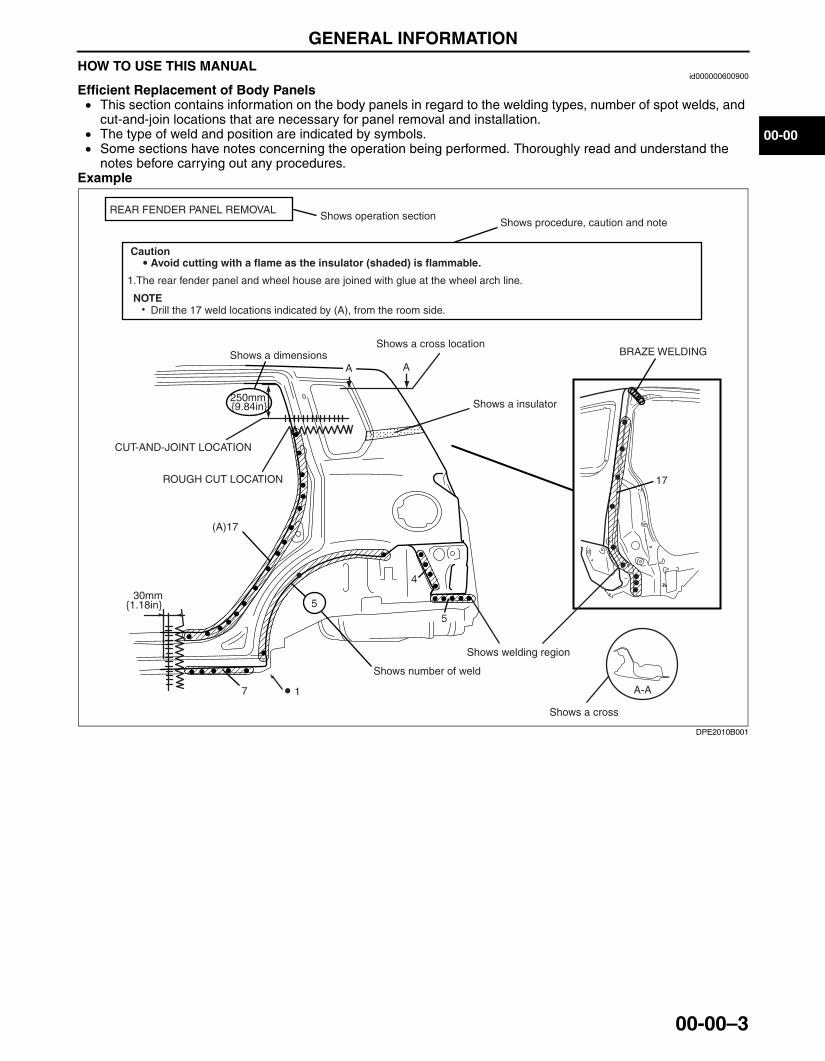
HOW TO USE THIS MANUALid000000600900
Efficient Replacement of Body Panels• This section contains information on the body panels in regard to the welding types, number of spot welds, and
cut-and-join locations that are necessary for panel removal and installation.• The type of weld and position are indicated by symbols.• Some sections have notes concerning the operation being performed. Thoroughly read and understand the
notes before carrying out any procedures.Example
REAR FENDER PANEL REMOVALShows operation section
Shows procedure, caution and note
BRAZE WELDING
Shows welding region
Shows a cross
Shows a insulator
Avoid cutting with a flame as the insulator (shaded) is flammable.
1.The rear fender panel and wheel house are joined with glue at the wheel arch line.
Drill the 17 weld locations indicated by (A), from the room side.
Caution
NOTE
CUT-AND-JOINT LOCATION
ROUGH CUT LOCATION
Shows a dimensions
{9.84in}250mm
A-A
30mm{1.18in}
Shows number of weld
Shows a cross location
A A
(A)17
17
4
5
7 1
5
DPE2010B001
3426-1U-06F(00-00).fm 3 ページ 2006年6月20日 火曜日 午後3時36分
GENERAL INFORMATION
00-00–4
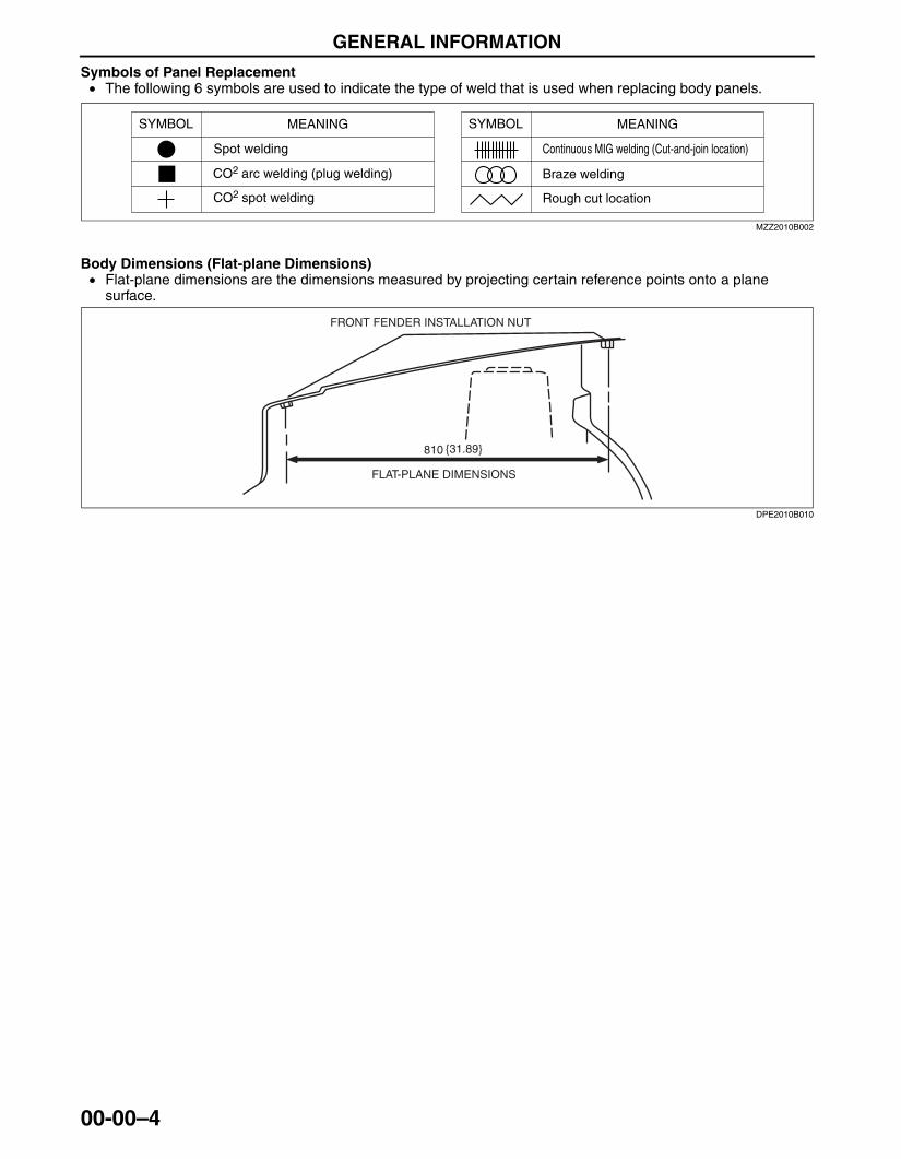
Symbols of Panel Replacement• The following 6 symbols are used to indicate the type of weld that is used when replacing body panels.
Body Dimensions (Flat-plane Dimensions)• Flat-plane dimensions are the dimensions measured by projecting certain reference points onto a plane
surface.
SYMBOL MEANING
Spot welding
CO2 arc welding (plug welding)
CO2 spot welding
SYMBOL MEANING
Continuous MIG welding (Cut-and-join location)
Braze welding
Rough cut location
MZZ2010B002
810 {31.89}
FLAT-PLANE DIMENSIONS
FRONT FENDER INSTALLATION NUT
DPE2010B010
3426-1U-06F(00-00).fm 4 ページ 2006年6月20日 火曜日 午後3時36分
GENERAL INFORMATION
00-00–5
00-00
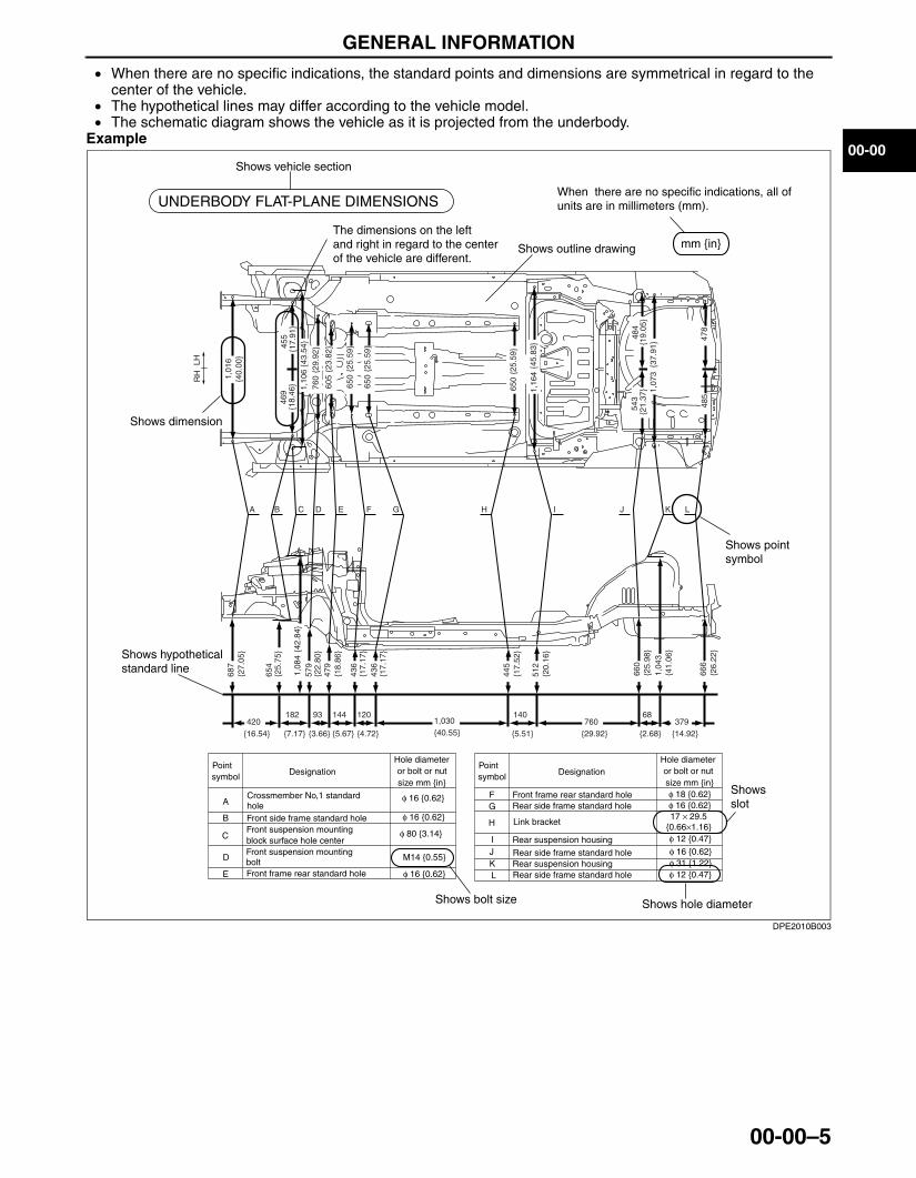
• When there are no specific indications, the standard points and dimensions are symmetrical in regard to the center of the vehicle.
• The hypothetical lines may differ according to the vehicle model.• The schematic diagram shows the vehicle as it is projected from the underbody.
Example
Shows vehicle section
When there are no specific indications, all of units are in millimeters (mm).
Shows outline drawing
Shows dimension
The dimensions on the left and right in regard to the center of the vehicle are different.
Shows hypothetical standard line
Shows point symbol
Pointsymbol Designation
Hole diameteror bolt or nut size mm {in}
Crossmember No,1 standard holeFront side frame standard holeFront suspension mountingblock surface hole centerFront suspension mounting bolt Front frame rear standard hole
Front frame rear standard holeRear side frame standard hole
Link bracket
Rear suspension housing
A
B
C
D
E
FG
H
IJK
Rear side frame standard hole
Rear side frame standard hole
Shows bolt size Shows hole diameter
Shows slot
mm {in}
UNDERBODY FLAT-PLANE DIMENSIONS
φ 16 {0.62}
φ 16 {0.62}
φ 16 {0.62}
M14 {0.55}
φ 80 {3.14}
Pointsymbol Designation
Hole diameteror bolt or nut size mm {in}
φ 16 {0.62}φ 31 {1.22}
φ 12 {0.47}
Rear suspension housingL φ 12 {0.47}
φ 16 {0.62}φ 18 {0.62}
17 × 29.5{0.66×1.16}
A B C D E F G H I J K L
1,01
6{4
0.00
}68
7{2
7.05
}
420182 93 144 120
{7.17} {3.66} {5.67} {4.72}
1,030140
76068
{5.51} {2.68}379
{16.54} {40.55} {29.92} {14.92}
{25.
75}
654
1,08
4{4
2.84
}57
9{2
2.80
}47
9{1
8.86
}
436
436
{17.
17}
{17.
17}
445
512
660
1,04
3
666
{17.
52}
{20.
16}
{25.
98}
{41.
06}
{26.
22}
1,10
6{4
3.54
}
1,16
4
543
485
484
{21.
37}
{19.
05}
478
1,07
3{3
7.91
}455
{17.
91}
469
{18.
46} 76
0
605
650
650
{29.
92}
{23.
82}
{25.
59}
{25.
59}
650
{45.
83}
{25.
59}
LHR
H
DPE2010B003
3426-1U-06F(00-00).fm 5 ページ 2006年6月20日 火曜日 午後3時36分
GENERAL INFORMATION
00-00–6
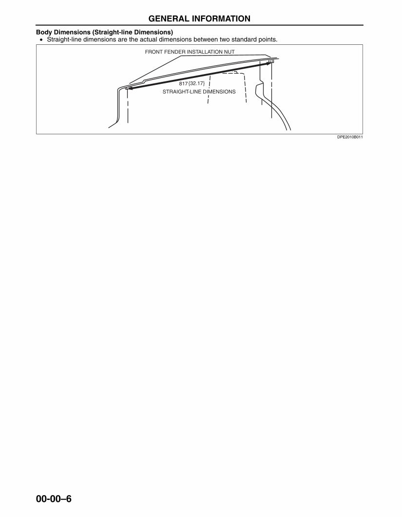
Body Dimensions (Straight-line Dimensions)• Straight-line dimensions are the actual dimensions between two standard points.
817
FRONT FENDER INSTALLATION NUT
STRAIGHT-LINE DIMENSIONS
{32.17}
DPE2010B011
3426-1U-06F(00-00).fm 6 ページ 2006年6月20日 火曜日 午後3時36分

GENERAL INFORMATION
00-00–7
00-00
• When there are no specific indications, the standard points and dimensions are symmetrical in regard to the center of the vehicle.
Example
1,128{44.41}
A
B
C
H
D
I
E
F
G
1,398{55.04}
1,406{55.35}
{42.01}1,067
799{31.46}
1,263{49.72}
1,048{41.26}
{33.50}
A
F G
B
H I
C D E,E'
Fr
Fr Fr
FrFr Fr
Fr
Fr
Fr
Front pillar inner designation
Front pillar inner designation
Front floor pan designation
Adjuster installation hole
Trim installation holeHarness installation holeChaker bracket installation hole
Chaker bracket installation hole
A
B
C
D
E
FGHI
f16
f17
f16
M14
f31 f12
f16 f18
17 ´ 29.5
Harness installation hole
Pointsymbol Designation
Hole diameteror bolt or nut size mm {in}
Pointsymbol Designation
Hole diameteror bolt or nut size mm {in}
Shows bolt size
Shows hole diameter
Shows slot
851
ROOM STRAIGHT-LINE DIMENSIONS (1)
Shows vehicle section
Shows dimension location
Shows outline drawingShows point symbol
Shows point indicationWithout apostrophe:RHWith apostrophe:LH
Shows details of the standard point location
Shows position and shape of the points
Shows dimension
No indication are shownwithin the outline drawing.
DPE2010B004
3426-1U-06F(00-00).fm 7 ページ 2006年6月20日 火曜日 午後3時36分
GENERAL INFORMATION
00-00–8
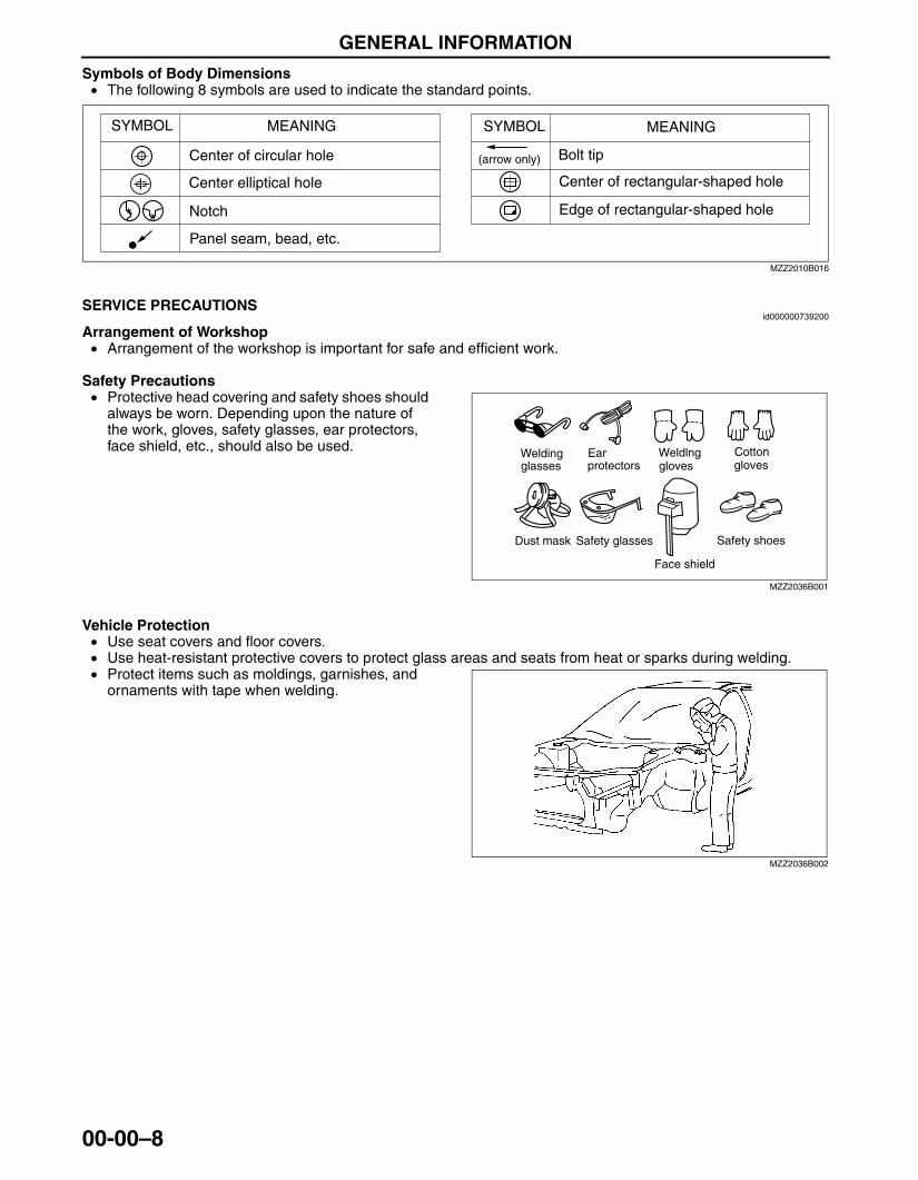
Symbols of Body Dimensions• The following 8 symbols are used to indicate the standard points.
End Of SieSOKYU_WM: GENERAL INFORMATIONSERVICE PRECAUTIONS
id000000739200
Arrangement of Workshop• Arrangement of the workshop is important for safe and efficient work.
Safety Precautions• Protective head covering and safety shoes should
always be worn. Depending upon the nature of the work, gloves, safety glasses, ear protectors, face shield, etc., should also be used.
Vehicle Protection• Use seat covers and floor covers.• Use heat-resistant protective covers to protect glass areas and seats from heat or sparks during welding.• Protect items such as moldings, garnishes, and
ornaments with tape when welding.
SYMBOL MEANING SYMBOL MEANING
Center of circular hole
Center elliptical hole
Notch
Panel seam, bead, etc.
Bolt tip(arrow only)
Center of rectangular-shaped hole
Edge of rectangular-shaped hole
MZZ2010B016
Weldingglasses
Earprotectors
Weldlnggloves
Cottongloves
Dust mask Safety glasses
Face shield
Safety shoes
MZZ2036B001
MZZ2036B002
3426-1U-06F(00-00).fm 8 ページ 2006年6月20日 火曜日 午後3時36分
GENERAL INFORMATION
00-00–9
00-00
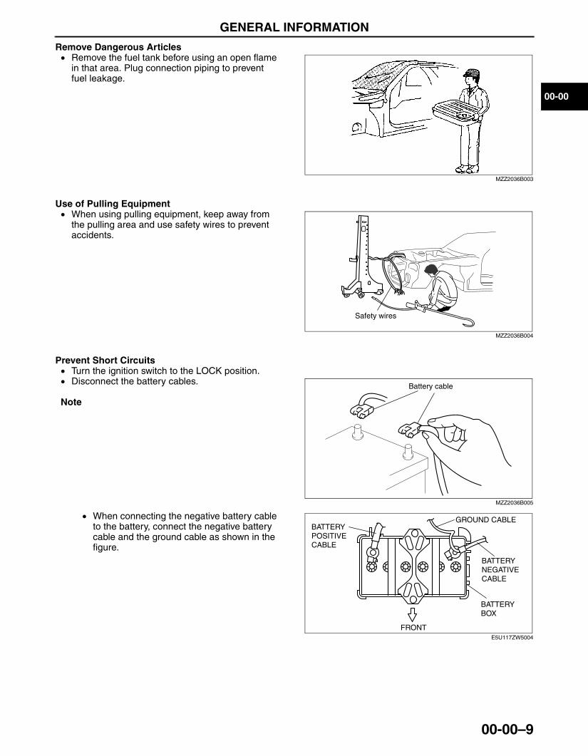
Remove Dangerous Articles• Remove the fuel tank before using an open flame
in that area. Plug connection piping to prevent fuel leakage.
Use of Pulling Equipment• When using pulling equipment, keep away from
the pulling area and use safety wires to prevent accidents.
Prevent Short Circuits• Turn the ignition switch to the LOCK position.• Disconnect the battery cables.
Note
• When connecting the negative battery cable to the battery, connect the negative battery cable and the ground cable as shown in the figure.
MZZ2036B003
Safety wires
MZZ2036B004
Battery cable
MZZ2036B005
GROUND CABLE
FRONT
BATTERY NEGATIVE CABLE
BATTERY POSITIVE CABLE
BATTERY BOX
E5U117ZW5004
3426-1U-06F(00-00).fm 9 ページ 2006年6月20日 火曜日 午後3時36分

GENERAL INFORMATION
00-00–10
• Securely connect the welding machine ground near the welding area.
End Of Sie
EFFICIENT REMOVAL OF BODY PANELSid000000739300
Body Measurements• Before removal or rough-cutting, first measure the
body at and around the damaged area against the standard reference dimension specifications. If there is deformation, use frame repair equipment to make a rough correction.
Prevention of Body Deformation• Use a clamp or a jack for removal and reinforce at
and around the rough-cutting location to prevent deforming of the body.
Selection of Cut-and-join Locations• For parts where complete replacement is not
feasible, careful cutting and joining operations should be followed. If the location to be cut is a flat area where there is no reinforcement, the selected cutting location should be where the welding distortion will be minimal.
Removal of Associated Parts• Protect moldings, garnishes, and ornaments with tape when removing associated parts.
Ground
MZZ2036B006
MZJ2038B001
MZJ2038B002
MZJ2038B003
3426-1U-06F(00-00).fm 10 ページ 2006年6月20日 火曜日 午後3時36分
GENERAL INFORMATION
00-00–11
00-00
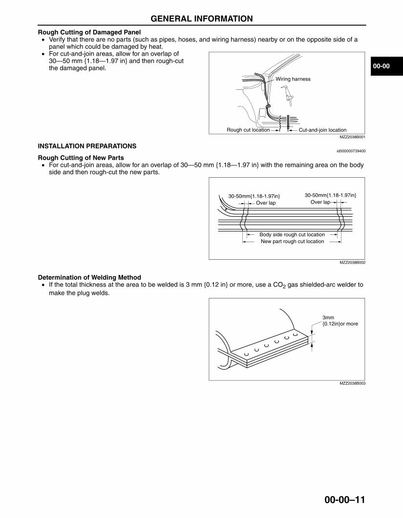
Rough Cutting of Damaged Panel• Verify that there are no parts (such as pipes, hoses, and wiring harness) nearby or on the opposite side of a
panel which could be damaged by heat.• For cut-and-join areas, allow for an overlap of
30—50 mm {1.18—1.97 in} and then rough-cut the damaged panel.
End Of Sie
INSTALLATION PREPARATIONSid000000739400
Rough Cutting of New Parts• For cut-and-join areas, allow for an overlap of 30—50 mm {1.18—1.97 in} with the remaining area on the body
side and then rough-cut the new parts.
Determination of Welding Method• If the total thickness at the area to be welded is 3 mm {0.12 in} or more, use a CO2 gas shielded-arc welder to
make the plug welds.
Wiring harness
Rough cut location Cut-and-join locationMZZ2038B001
Over lap Over lap
Body side rough cut locationNew part rough cut location
30-50mm{1.18-1.97in} 30-50mm{1.18-1.97in}
MZZ2038B002
3mm{0.12in}or more
MZZ2038B003
3426-1U-06F(00-00).fm 11 ページ 2006年6月20日 火曜日 午後3時36分
GENERAL INFORMATION
00-00–12
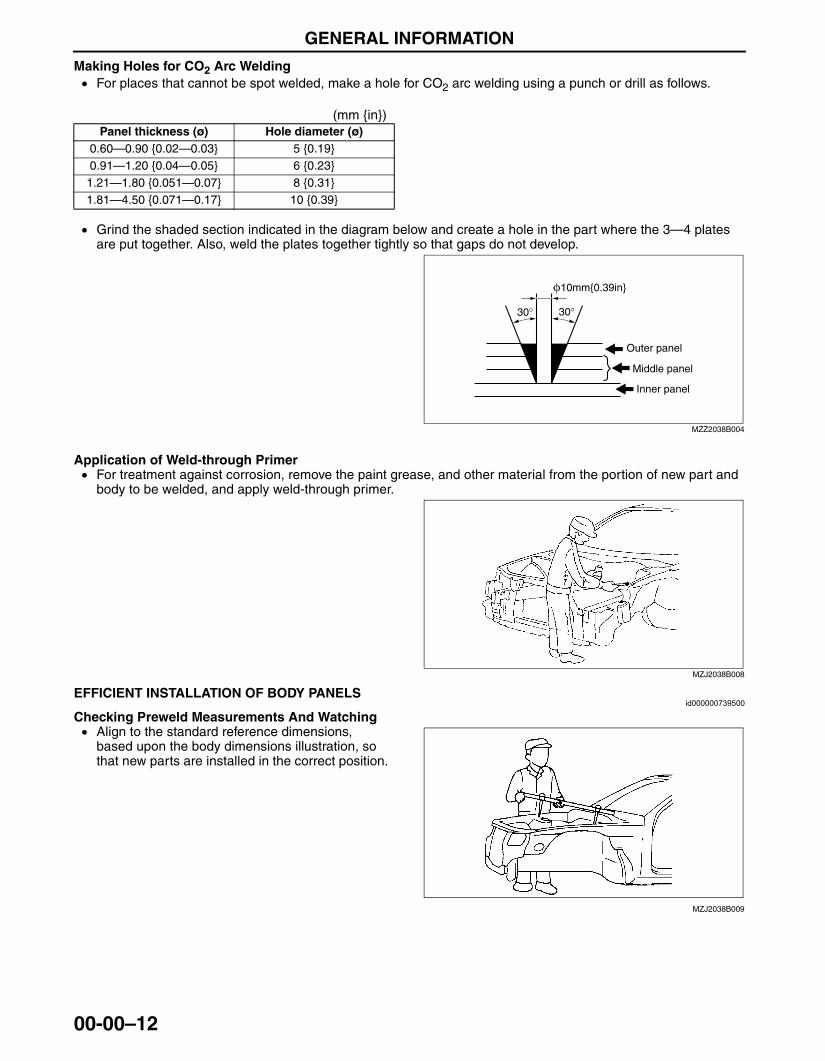
Making Holes for CO2 Arc Welding• For places that cannot be spot welded, make a hole for CO2 arc welding using a punch or drill as follows.
(mm {in})
• Grind the shaded section indicated in the diagram below and create a hole in the part where the 3—4 plates are put together. Also, weld the plates together tightly so that gaps do not develop.
Application of Weld-through Primer• For treatment against corrosion, remove the paint grease, and other material from the portion of new part and
body to be welded, and apply weld-through primer.End Of Sie
EFFICIENT INSTALLATION OF BODY PANELSid000000739500
Checking Preweld Measurements And Watching• Align to the standard reference dimensions,
based upon the body dimensions illustration, so that new parts are installed in the correct position.
Panel thickness (ø) Hole diameter (ø)0.60—0.90 {0.02—0.03} 5 {0.19}0.91—1.20 {0.04—0.05} 6 {0.23}1.21—1.80 {0.051—0.07} 8 {0.31}1.81—4.50 {0.071—0.17} 10 {0.39}
φ10mm{0.39in}
Outer panel
Middle panel
Inner panel
30° 30°
MZZ2038B004
MZJ2038B008
MZJ2038B009
3426-1U-06F(00-00).fm 12 ページ 2006年6月20日 火曜日 午後3時36分
GENERAL INFORMATION
00-00–13
00-00
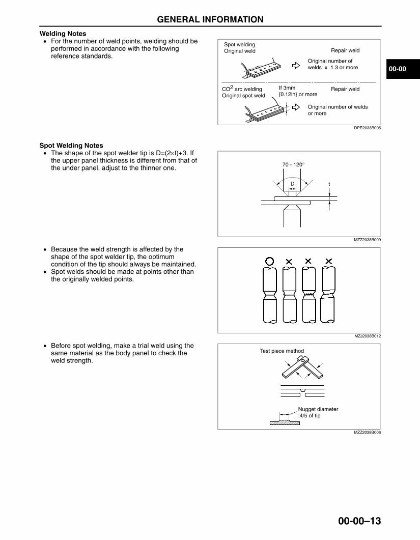
Welding Notes• For the number of weld points, welding should be
performed in accordance with the following reference standards.
Spot Welding Notes• The shape of the spot welder tip is D=(2×t)+3. If
the upper panel thickness is different from that of the under panel, adjust to the thinner one.
• Because the weld strength is affected by the shape of the spot welder tip, the optimum condition of the tip should always be maintained.
• Spot welds should be made at points other than the originally welded points.
• Before spot welding, make a trial weld using the same material as the body panel to check the weld strength.
Spot welding Original weld
If 3mm{0.12in} or more
Original number ofwelds x 1.3 or more
CO2 arc weldingOriginal spot weld
Repair weld
Repair weld
Original number of weldsor more
DPE2038B005
D
70 - 120°
t
MZZ2038B009
MZJ2038B012
Test piece method
Nugget diameter:4/5 of tip
MZZ2038B006
3426-1U-06F(00-00).fm 13 ページ 2006年6月20日 火曜日 午後3時36分
GENERAL INFORMATION
00-00–14
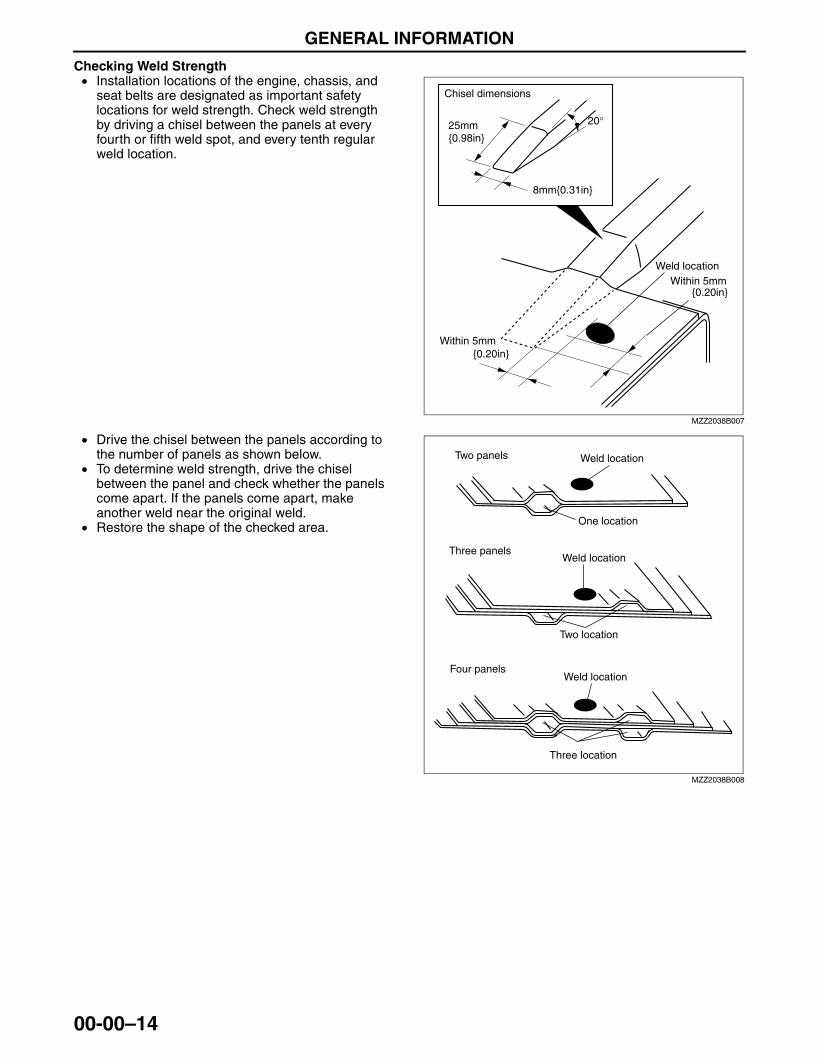
Checking Weld Strength• Installation locations of the engine, chassis, and
seat belts are designated as important safety locations for weld strength. Check weld strength by driving a chisel between the panels at every fourth or fifth weld spot, and every tenth regular weld location.
• Drive the chisel between the panels according to the number of panels as shown below.
• To determine weld strength, drive the chisel between the panel and check whether the panels come apart. If the panels come apart, make another weld near the original weld.
• Restore the shape of the checked area.End Of Sie
Chisel dimensions
25mm{0.98in}
8mm{0.31in}
{0.20in}
{0.20in}
20°
Weld location
Within 5mm
Within 5mm
MZZ2038B007
Two panels Weld location
Three panelsWeld location
One location
Two location
Four panelsWeld location
Three location
MZZ2038B008
3426-1U-06F(00-00).fm 14 ページ 2006年6月20日 火曜日 午後3時36分
GENERAL INFORMATION
00-00–15
00-00
ANTICORROSION, SOUND INSULATION, AND VIBRATION INSULATIONid000000739600
Body Sealing• Apply body sealer where necessary.• For locations where application of body sealer is difficult after installation, apply it before installation.
Application of Undercoating• Apply an undercoat to the required location of the body.
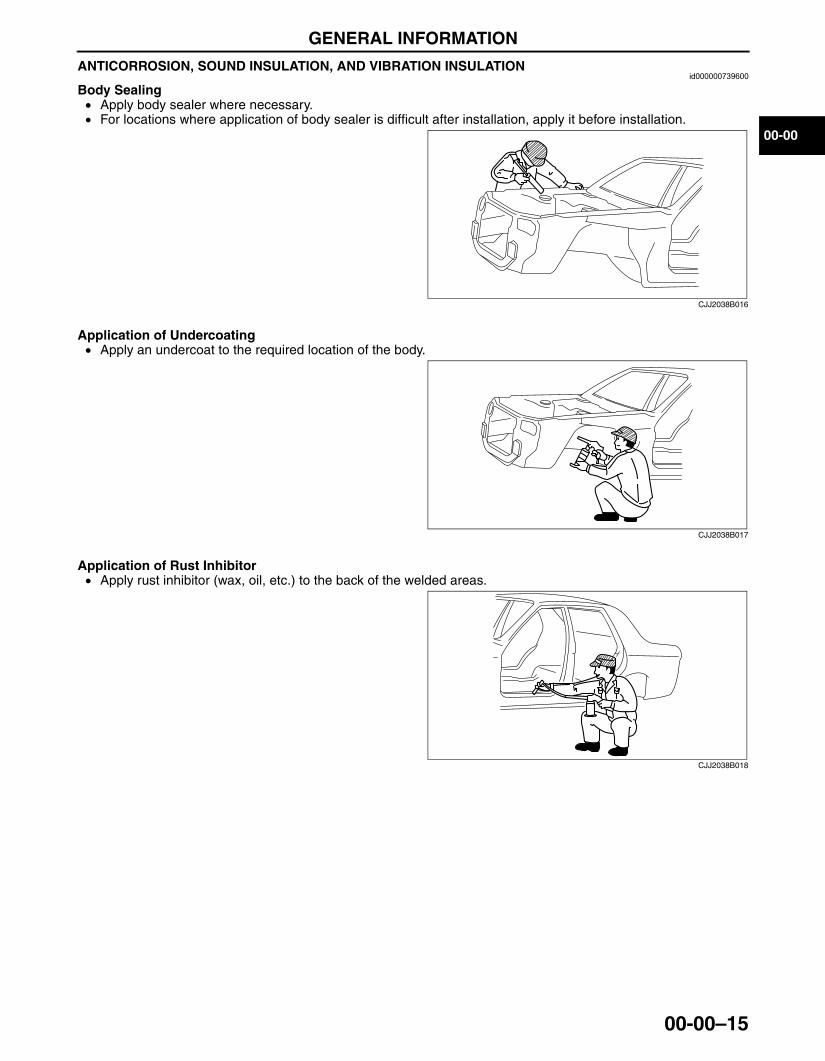
Application of Rust Inhibitor• Apply rust inhibitor (wax, oil, etc.) to the back of the welded areas.
CJJ2038B016
CJJ2038B017
CJJ2038B018
3426-1U-06F(00-00).fm 15 ページ 2006年6月20日 火曜日 午後3時36分
GENERAL INFORMATION
00-00–16
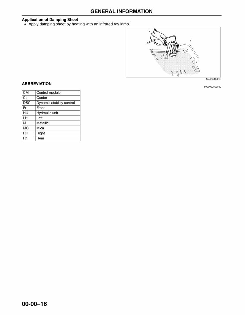
Application of Damping Sheet• Apply damping sheet by heating with an infrared ray lamp.
End Of SieSOKYU_NG: GENERAL INFORMATION
ABBREVIATIONid000000000800
End Of Sie
CJJ2038B019
CM Control moduleCtr CenterDSC Dynamic stability controlFr FrontHU Hydraulic unitLH LeftM MetallicMC MicaRH RightRr Rear
3426-1U-06F(00-00).fm 16 ページ 2006年6月20日 火曜日 午後3時36分
09-80A–1
09BODY & ACCESSORIESSECTION
09-80A
Toc of SCTBODY STRUCTURE[CONSTRUCTION] . . . . . . . . .09-80A
BODY STRUCTURE[PANEL REPLACEMENT] . . . . . . . . . .09-80B
BODY STRUCTURE[WATER-PROOF AND RUST PREVENTIVE]. . . . . . . . . . . . .09-80C
BODY STRUCTURE[DIMENSIONS] . . . . . . . . . . . 09-80D
BODY STRUCTURE[PLASTIC BODY PARTS] . . . 09-80E
Toc of SCT
09-80A BODY STRUCTURE [CONSTRUCTION]BODY COMPONENTS CONSTRUCTION
[CONSTRUCTION]. . . . . . . . . . . . . . . . . 09-80A–2ADOPTION OF ULTRA HIGH-TENSION
STEEL[CONSTRUCTION] . . . . . . . . . . . 09-80A–5
Characteristics of Ultra High-Tensile Steel Plates . . . . . . . . . . . . . . . . . . . . 09-80A–5
Range of Use and Cautions for Service . . . . . . . . . . . . . . 09-80A–5
End of TocBM: CONSTRUCTION
3426-1U-06F(09-80A).fm 1 ページ 2006年6月20日 火曜日 午後3時37分
BODY STRUCTURE [CONSTRUCTION]
09-80A–2
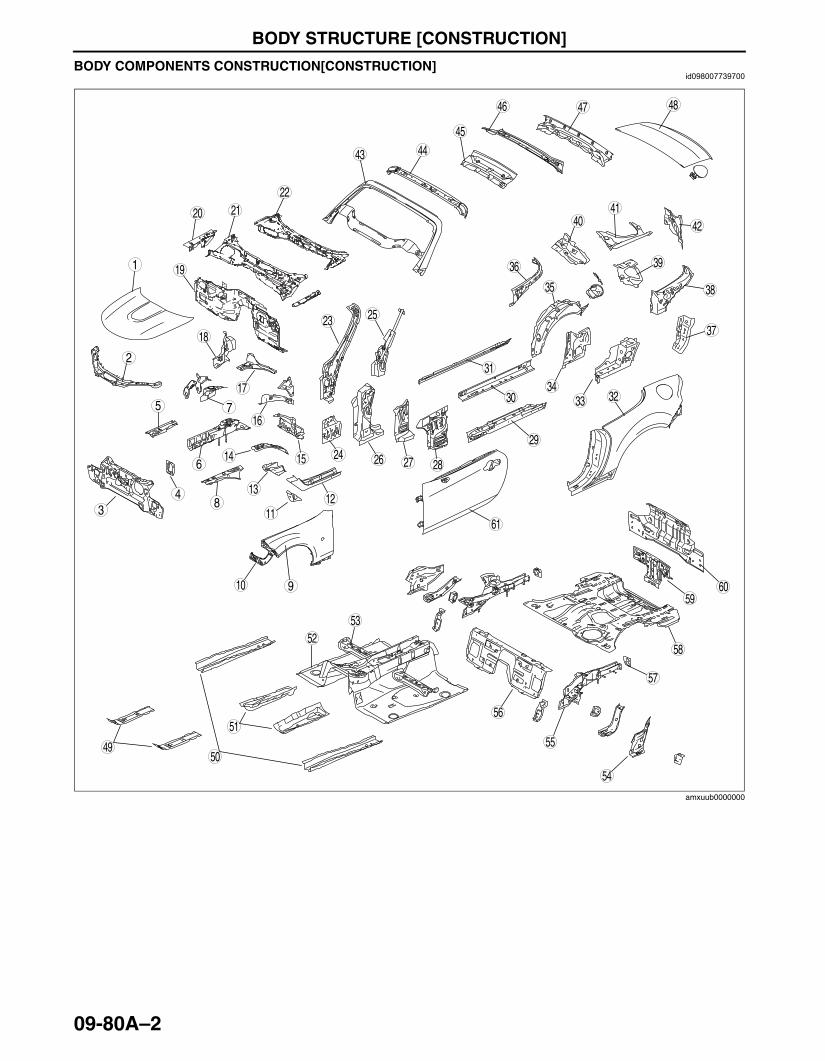
BODY COMPONENTS CONSTRUCTION[CONSTRUCTION]id098007739700
.
9
8
75
43
1
2
10
6
19
18
17
15
16
14
13
1112
20
29
2827
25
2624
23
2122
30
39
38
37
35
36
3433
31
32
40
49
4847
45
46
4443
4142
50
59
58
57
55
56
54
53
51
52
60
61
amxuub0000000
3426-1U-06F(09-80A).fm 2 ページ 2006年6月20日 火曜日 午後3時37分
BODY STRUCTURE [CONSTRUCTION]
09-80A–3
09-80A
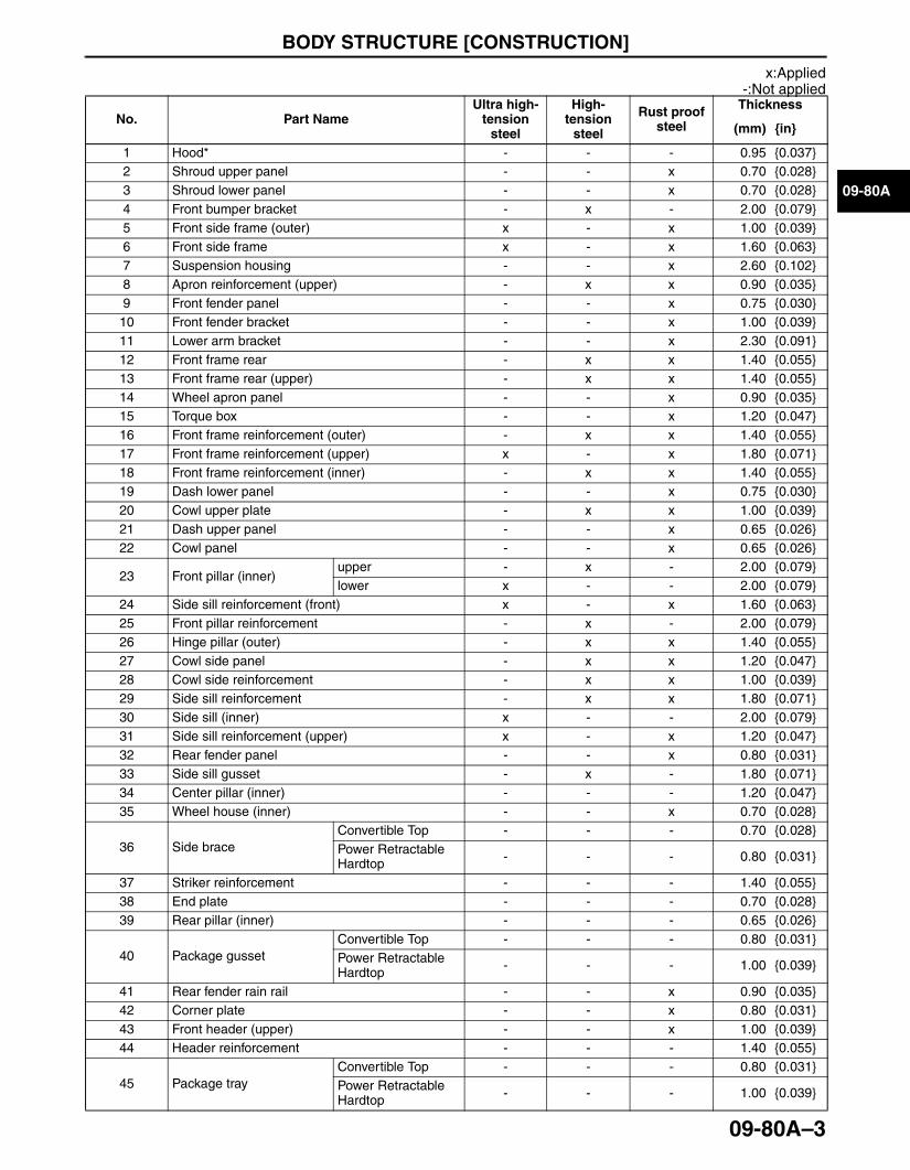
x:Applied-:Not applied
No. Part NameUltra high-
tension steel
High- tension
steel
Rust proof steel
Thickness
(mm) {in}
1 Hood* - - - 0.95 {0.037}2 Shroud upper panel - - x 0.70 {0.028}3 Shroud lower panel - - x 0.70 {0.028}4 Front bumper bracket - x - 2.00 {0.079}5 Front side frame (outer) x - x 1.00 {0.039}6 Front side frame x - x 1.60 {0.063}7 Suspension housing - - x 2.60 {0.102}8 Apron reinforcement (upper) - x x 0.90 {0.035}9 Front fender panel - - x 0.75 {0.030}10 Front fender bracket - - x 1.00 {0.039}11 Lower arm bracket - - x 2.30 {0.091}12 Front frame rear - x x 1.40 {0.055}13 Front frame rear (upper) - x x 1.40 {0.055}14 Wheel apron panel - - x 0.90 {0.035}15 Torque box - - x 1.20 {0.047}16 Front frame reinforcement (outer) - x x 1.40 {0.055}17 Front frame reinforcement (upper) x - x 1.80 {0.071}18 Front frame reinforcement (inner) - x x 1.40 {0.055}19 Dash lower panel - - x 0.75 {0.030}20 Cowl upper plate - x x 1.00 {0.039}21 Dash upper panel - - x 0.65 {0.026}22 Cowl panel - - x 0.65 {0.026}
23 Front pillar (inner)upper - x - 2.00 {0.079}lower x - - 2.00 {0.079}
24 Side sill reinforcement (front) x - x 1.60 {0.063}25 Front pillar reinforcement - x - 2.00 {0.079}26 Hinge pillar (outer) - x x 1.40 {0.055}27 Cowl side panel - x x 1.20 {0.047}28 Cowl side reinforcement - x x 1.00 {0.039}29 Side sill reinforcement - x x 1.80 {0.071}30 Side sill (inner) x - - 2.00 {0.079}31 Side sill reinforcement (upper) x - x 1.20 {0.047}32 Rear fender panel - - x 0.80 {0.031}33 Side sill gusset - x - 1.80 {0.071}34 Center pillar (inner) - - - 1.20 {0.047}35 Wheel house (inner) - - x 0.70 {0.028}
36 Side braceConvertible Top - - - 0.70 {0.028}Power Retractable Hardtop - - - 0.80 {0.031}
37 Striker reinforcement - - - 1.40 {0.055}38 End plate - - - 0.70 {0.028}39 Rear pillar (inner) - - - 0.65 {0.026}
40 Package gussetConvertible Top - - - 0.80 {0.031}Power Retractable Hardtop - - - 1.00 {0.039}
41 Rear fender rain rail - - x 0.90 {0.035}42 Corner plate - - x 0.80 {0.031}43 Front header (upper) - - x 1.00 {0.039}44 Header reinforcement - - - 1.40 {0.055}
45 Package trayConvertible Top - - - 0.80 {0.031}Power Retractable Hardtop - - - 1.00 {0.039}
3426-1U-06F(09-80A).fm 3 ページ 2006年6月20日 火曜日 午後4時20分
BODY STRUCTURE [CONSTRUCTION]
09-80A–4
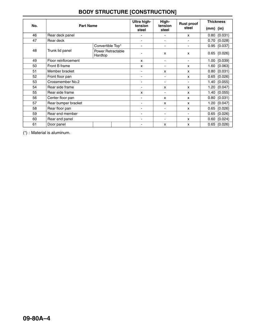
(*) : Material is aluminum.
End Of Sie
46 Rear deck panel - - x 0.80 {0.031}47 Rear deck - - - 0.70 {0.028}
48 Trunk lid panelConvertible Top* - - - 0.95 {0.037}Power Retractable Hardtop - x x 0.65 {0.026}
49 Floor reinforcement x - - 1.00 {0.039}50 Front B frame x - x 1.60 {0.063}51 Member bracket - x x 0.80 {0.031}52 Front floor pan - - x 0.65 {0.026}53 Crossmember No.2 - - - 1.40 {0.055}54 Rear side frame - x x 1.20 {0.047}55 Rear side frame x - x 1.40 {0.055}56 Center floor pan - x x 0.80 {0.031}57 Rear bumper bracket - x x 1.20 {0.047}58 Rear floor pan - - x 0.65 {0.026}59 Rear end member - - - 0.65 {0.026}60 Rear end panel - - x 0.60 {0.024}61 Door panel - x x 0.65 {0.026}
No. Part NameUltra high-
tension steel
High- tension
steel
Rust proof steel
Thickness
(mm) {in}
3426-1U-06F(09-80A).fm 4 ページ 2006年6月20日 火曜日 午後4時20分
BODY STRUCTURE [CONSTRUCTION]
09-80A–5
09-80A
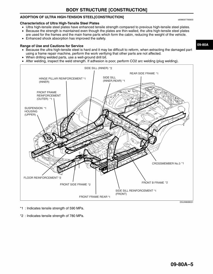
ADOPTION OF ULTRA HIGH-TENSION STEEL[CONSTRUCTION]id098007785600
Characteristics of Ultra High-Tensile Steel Plates• Ultra high-tensile steel plates have enhanced tensile strength compared to previous high-tensile steel plates.• Because the strength is maintained even though the plates are thin-walled, the ultra high-tensile steel plates
are used for the frames and the main frame parts which form the cabin, reducing the weight of the vehicle.• Enhanced shock absorption has improved the safety.
Range of Use and Cautions for Service• Because the ultra high-tensile steel is hard and it may be difficult to reform, when extracting the damaged part
using a frame repair machine, perform the work verifying that other parts are not affected.• When drilling welded parts, use a well-ground drill bit.• After welding, inspect the weld strength. If adhesion is poor, perform CO2 arc welding (plug welding).
*1 : Indicates tensile strength of 590 MPa.
*2 : Indicates tensile strength of 780 MPa.
End Of Sie
*2 FRONT SIDE FRAME
*1
*1
REAR SIDE FRAME
CROSSMEMBER No.3
*2FLOOR REINFORCEMENT
*1
*1
SUSPENSIONHOUSING(UPPER)
*1HINGE PILLAR REINFORCEMENT(INNER)
*1FRONT FRAME REAR
*1
*2
SIDE SILL REINFORCEMENT(FRONT)
FRONT B FRAME
*2SIDE SILL (INNER)
SIDE SILL(INNER,REAR)
FRONT FRAMEREINFORCEMENT(OUTER)
*1
D5U0980B031
3426-1U-06F(09-80A).fm 5 ページ 2006年6月20日 火曜日 午後3時37分


BODY STRUCTURE [PANEL REPLACEMENT]
09-80B–1
09-80B
09-80B BODY STRUCTURE [PANEL REPLACEMENT]SHROUD UPPER PANEL REMOVAL
[PANEL REPLACEMENT]. . . . . . . . . . . 09-80B–3SHROUD UPPER PANEL INSTALLATION
[PANEL REPLACEMENT]. . . . . . . . . . . 09-80B–4SHROUD LOWER PANEL REMOVAL
[PANEL REPLACEMENT]. . . . . . . . . . . 09-80B–5SHROUD LOWER PANEL INSTALLTION
[PANEL REPLACEMENT]. . . . . . . . . . . 09-80B–6FRONT BUMPER BRACKET
INSTALLATION[PANEL REPLACEMENT]. . . . . . . . . . . . . . . . . . 09-80B–7
FRONT BUMPER BRACKET REMOVAL[PANEL REPLACEMENT]. . . . . . . . . . . 09-80B–8
CROSSMEMBER No.1 REMOVAL[PANEL REPLACEMENT]. . . . . . . . . . . 09-80B–8
CROSSMEMBER No.1 INSTALLATION[PANEL REPLACEMENT]. . . . . . . . . . . 09-80B–11
COWL SIDE REINFORCEMENT REMOVAL[PANEL REPLACEMENT]. . . . . . . . . . . . . . . . . . 09-80B–13
COWL SIDE REINFORCEMENT INSTALLATION[PANEL REPLACEMENT]. . . . . . . . . . . . . . . . . . 09-80B–14
APRON REINFORCEMENT OMPONENT REMOVAL[PANEL REPLACEMENT]. . . . . . . . . . . 09-80B–15
APRON REINFORCEMENT COMPONENT INSTALLATION[PANEL REPLACEMENT]. . . . . . . . . . . 09-80B–16
APRON REINFORCEMENT (LOWER) REMOVAL[PANEL REPLACEMENT]. . . . . . . . . . . . . . . . . . 09-80B–17
APRON REINFORCEMENT (LOWER) INSTALLATION[PANEL REPLACEMENT]. . . . . . . . . . . . . . . . . . 09-80B–18
FRONT SIDE FRAME REAR REINFORCEMENT REMOVAL[PANEL REPLACEMENT]. . . . . . . . . . . 09-80B–19
FRONT SIDE FRAME REAR REINFORCEMENT INSTALLATION[PANEL REPLACEMENT]. . . . . . . . . . . 09-80B–20
FRONT SIDE FRAME (OUTER) REMOVAL[PANEL REPLACEMENT]. . . . . . . . . . . . . . . . . . 09-80B–21
FRONT SIDE FRAME (OUTER) INSTALLATION[PANEL REPLACEMENT]. . . . . . . . . . . . . . . . . . 09-80B–22
FRONT SIDE FRAME COMPONENT REMOVAL[PANEL REPLACEMENT]. . . . . . . . . . . . . . . . . . 09-80B–23
FRONT SIDE FRAME COMPONENT INSTALLATION[PANEL REPLACEMENT]. . . . . . . . . . . . . . . . . . 09-80B–24
FRONT SIDE FRAME (PARTIAL CUTTING) REMOVAL[PANEL REPLACEMENT]. . . . . . . . . . . 09-80B–25
FRONT SIDE FRAME (PARTIAL CUTTING) INSTALLATION[PANEL REPLACEMENT]. . . . . . . . . . . 09-80B–26
FRONT FRAME COMPONENT (FRONT) REMOVAL[PANEL REPLACEMENT]. . . . . . . . . . . . . . . . . . 09-80B–28
FRONT FRAME COMPONENT (FRONT) INSTALLATION[PANEL REPLACEMENT] . . . . . . . . . . . . . . . . . . 09-80B–30
FRONT FRAME COMPONENT REMOVAL[PANEL REPLACEMENT] . . . . . . . . . . . . . . . . . . 09-80B–32
FRONT FRAME COMPONENT INSTALLATION[PANEL REPLACEMENT] . . . . . . . . . . . . . . . . . . 09-80B–34
TORQUE BOX COMPONENT REMOVAL[PANEL REPLACEMENT] . . . . . . . . . . . . . . . . . . 09-80B–36
TORQUE BOX COMPONENT INSTALLATION[PANEL REPLACEMENT] . . . . . . . . . . . . . . . . . . 09-80B–38
FRONT PILLAR (OUTER) REMOVAL[PANEL REPLACEMENT] . . . . . . . . . . . 09-80B–40
FRONT PILLAR (OUTER) INSTALLATION[PANEL REPLACEMENT] . . . . . . . . . . . . . . . . . . 09-80B–41
HINGE PILLAR (OUTER) REMOVAL[PANEL REPLACEMENT] . . . . . . . . . . . 09-80B–43
HINGE PILLAR (OUTER) INSTALLATION[PANEL REPLACEMENT] . . . . . . . . . . . . . . . . . . 09-80B–47
REAR FENDER PANEL (LOWER) REMOVAL[PANEL REPLACEMENT] . . . . . . . . . . . . . . . . . . 09-80B–51
REAR FENDER PANEL (LOWER) INSTALLATION[PANEL REPLACEMENT] . . . . . . . . . . . . . . . . . . 09-80B–52
REAR FENDER PANEL REMOVAL[PANEL REPLACEMENT] . . . . . . . . . . . 09-80B–53
Convertible Top . . . . . . . . . . . . . . . . . . . 09-80B–54Power Retractable Hardtop . . . . . . . . . . 09-80B–55
REAR FENDER PANEL INSTALLATION[PANEL REPLACEMENT] . . . . . . . . . . . 09-80B–56
Convertible Top . . . . . . . . . . . . . . . . . . . 09-80B–57Power Retractable Hardtop . . . . . . . . . . 09-80B–57
SIDE SILL REINFORCEMENT (FRONT) REMOVAL[PANEL REPLACEMENT] . . . . . . . . . . . . . . . . . . 09-80B–59
SIDE SILL REINFORCEMENT (FRONT) INSTALLATION[PANEL REPLACEMENT] . . . . . . . . . . . . . . . . . . 09-80B–60
SIDE SILL REINFORCEMENT (CENTER) REMOVAL[PANEL REPLACEMENT] . . . . . . . . . . . . . . . . . . 09-80B–61
SIDE SILL REINFORCEMENT (CENTER) INSTALLATION[PANEL REPLACEMENT] . . . . . . . . . . . . . . . . . . 09-80B–62
SIDE SILL REINFORCEMENT REMOVAL[PANEL REPLACEMENT] . . . . . . . . . . . . . . . . . . 09-80B–63
SIDE SILL REINFORCEMENT INSTALLATION[PANEL REPLACEMENT] . . . . . . . . . . . . . . . . . . 09-80B–64
REAR END PANEL REMOVAL[PANEL REPLACEMENT] . . . . . . . . . . . 09-80B–65
REAR END PANEL INSTALLATION[PANEL REPLACEMENT] . . . . . . . . . . . 09-80B–65
3426-1U-06F(09-80B).fm 1 ページ 2006年6月20日 火曜日 午後7時32分

BODY STRUCTURE [PANEL REPLACEMENT]
09-80B–2
CORNER PLATE REMOVAL[PANEL REPLACEMENT] . . . . . . . . . . . 09-80B–66
CORNER PLATE INSTALLATION[PANEL REPLACEMENT] . . . . . . . . . . . 09-80B–66
REAR FENDER RAIN RAIL (PARTIAL CUTTING) REMOVAL[PANEL REPLACEMENT] . . . . . . . . . . . 09-80B–67
REAR FENDER RAIN RAIL (PARTIAL CUTTING) INSTALLATION[PANEL REPLACEMENT] . . . . . . . . . . . 09-80B–68
REAR DECK PANEL REMOVAL[PANEL REPLACEMENT] . . . . . . . . . . . 09-80B–69
Convertible Top . . . . . . . . . . . . . . . . . . . 09-80B–69Power Retractable Hardtop . . . . . . . . . . 09-80B–70
REAR DECK PANEL INSTALLATION[PANEL REPLACEMENT] . . . . . . . . . . . 09-80B–71
Convertible Top . . . . . . . . . . . . . . . . . . . 09-80B–71Power Retractable Hardtop . . . . . . . . . . 09-80B–72
REAR FENDER RAIN RAIL REMOVAL[PANEL REPLACEMENT] . . . . . . . . . . . 09-80B–73
Convertible Top . . . . . . . . . . . . . . . . . . . 09-80B–73Power Retractable Hardtop . . . . . . . . . . 09-80B–74
REAR FENDER RAIN RAIL INSTALLATION[PANEL REPLACEMENT] . . . . . . . . . . . . . . . . . . 09-80B–75
Convertible Top . . . . . . . . . . . . . . . . . . . 09-80B–75Power Retractable Hardtop . . . . . . . . . . 09-80B–76
END PLATE REMOVAL[PANEL REPLACEMENT]. . . . . . . . . . . 09-80B–77
END PLATE INSTALLATION[PANEL REPLACEMENT]. . . . . . . . . . . 09-80B–78
CORNER JUNCTION REMOVAL[PANEL REPLACEMENT]. . . . . . . . . . . 09-80B–80
CORNER JUNCTION INSTALLATION[PANEL REPLACEMENT]. . . . . . . . . . . 09-80B–81
WHEEL HOUSE (INNER) REMOVAL[PANEL REPLACEMENT]. . . . . . . . . . . 09-80B–82
WHEEL HOUSE (INNER) INSTALLATION[PANEL REPLACEMENT]. . . . . . . . . . . . . . . . . . 09-80B–83
REAR FLOOR PAN REMOVAL[PANEL REPLACEMENT]. . . . . . . . . . . 09-80B–84
REAR FLOOR PAN INSTALLATION[PANEL REPLACEMENT]. . . . . . . . . . . 09-80B–86
REAR SIDE FRAME (PARTIAL CUTTING) REMOVAL[PANEL REPLACEMENT]. . . . . . . . . . . 09-80B–88
REAR SIDE FRAME (PARTIAL CUTTING) INSTALLATION[PANEL REPLACEMENT]. . . . . . . . . . . 09-80B–88
FRONT HEADER REMOVAL[PANEL REPLACEMENT]. . . . . . . . . . . 09-80B–90
FRONT HEADER INSTALLATION[PANEL REPLACEMENT]. . . . . . . . . . . 09-80B–91
End of TocBM: SHROUD PANEL
3426-1U-06F(09-80B).fm 2 ページ 2006年6月20日 火曜日 午後7時32分
BODY STRUCTURE [PANEL REPLACEMENT]
09-80B–3
09-80B
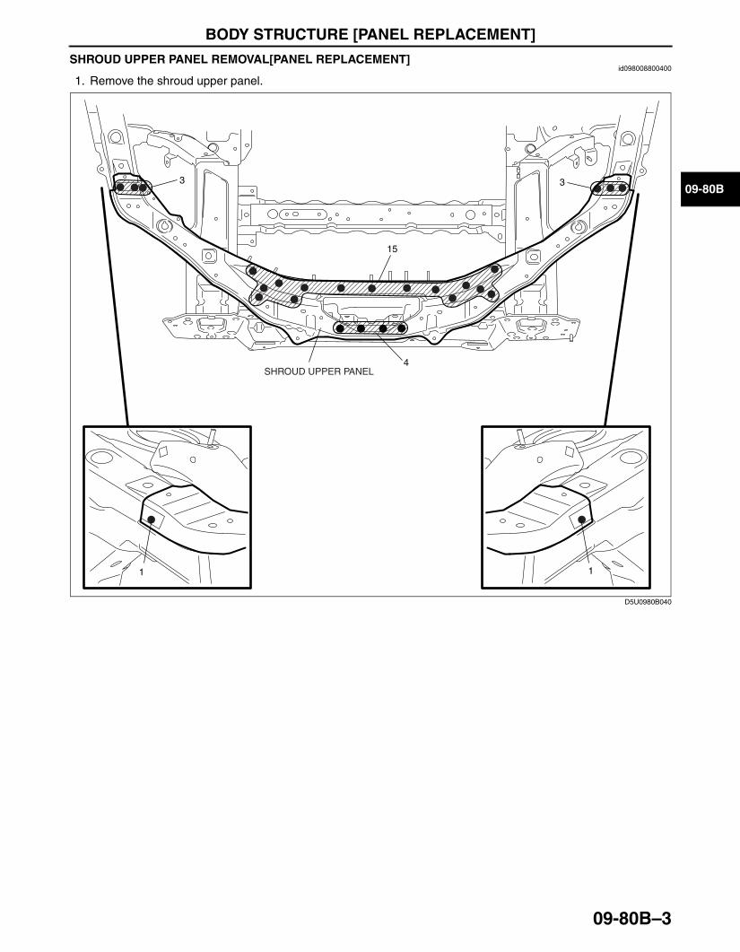
SHROUD UPPER PANEL REMOVAL[PANEL REPLACEMENT]id098008800400
1. Remove the shroud upper panel.
End Of Sie
33
1
15
1
SHROUD UPPER PANEL4
D5U0980B040
3426-1U-06F(09-80B).fm 3 ページ 2006年6月20日 火曜日 午後7時32分
BODY STRUCTURE [PANEL REPLACEMENT]
09-80B–4
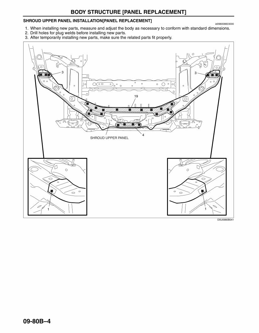
SHROUD UPPER PANEL INSTALLATION[PANEL REPLACEMENT]id098008603000
1. When installing new parts, measure and adjust the body as necessary to conform with standard dimensions.2. Drill holes for plug welds before installing new parts.3. After temporarily installing new parts, make sure the related parts fit properly.
End Of Sie
33
1
19
1
SHROUD UPPER PANEL4
D5U0980B041
3426-1U-06F(09-80B).fm 4 ページ 2006年6月20日 火曜日 午後7時32分
BODY STRUCTURE [PANEL REPLACEMENT]
09-80B–5
09-80B
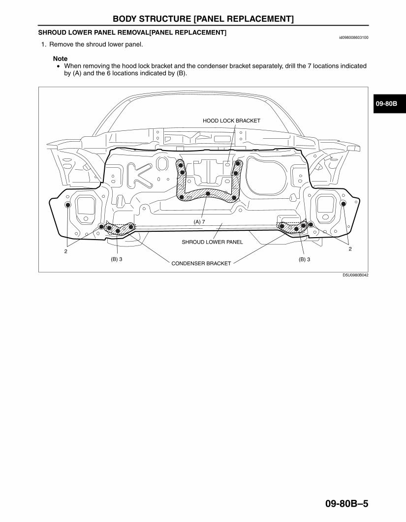
SHROUD LOWER PANEL REMOVAL[PANEL REPLACEMENT]id098008603100
1. Remove the shroud lower panel.
Note• When removing the hood lock bracket and the condenser bracket separately, drill the 7 locations indicated
by (A) and the 6 locations indicated by (B).
End Of Sie
22
(B) 3(B) 3
(A) 7
CONDENSER BRACKET
HOOD LOCK BRACKET
SHROUD LOWER PANEL
D5U0980B042
3426-1U-06F(09-80B).fm 5 ページ 2006年6月20日 火曜日 午後7時32分

BODY STRUCTURE [PANEL REPLACEMENT]
09-80B–6
SHROUD LOWER PANEL INSTALLTION[PANEL REPLACEMENT]id098008603200
1. When installing new parts, measure and adjust the body as necessary to conform with standard dimensions.2. Drill holes for plug welds before installing new parts.3. After temporarily installing new parts, make sure the related parts fit properly.
Note• When replacing the hood lock bracket and the condenser bracket separately, weld the 7 locations
indicated by (A) and the 6 locations indicated by (B).
End Of SieBM: BUMPER BRACKET
22
(B) 3(B) 3
(A) 7
CONDENSER BRACKET
SHROUD LOWER PANEL
HOOD LOCK BRACKET
D5U0980B043
3426-1U-06F(09-80B).fm 6 ページ 2006年6月20日 火曜日 午後7時32分

BODY STRUCTURE [PANEL REPLACEMENT]
09-80B–7
09-80B
FRONT BUMPER BRACKET INSTALLATION[PANEL REPLACEMENT]id098008743200
1. When installing new parts, measure and adjust the body as necessary to conform with standard dimensions.2. Drill holes for plug welds before installing new parts.3. After temporarily installing new parts, make sure the related parts fit properly.
End Of Sie
1
2
2
2
FRONT BUMPER BRACKET
D5U0980B045
3426-1U-06F(09-80B).fm 7 ページ 2006年6月20日 火曜日 午後7時32分
BODY STRUCTURE [PANEL REPLACEMENT]
09-80B–8
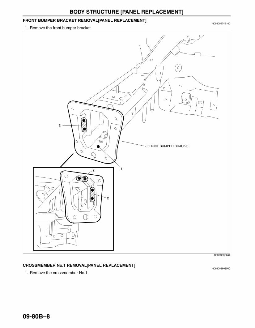
FRONT BUMPER BRACKET REMOVAL[PANEL REPLACEMENT]id098008743100
1. Remove the front bumper bracket.
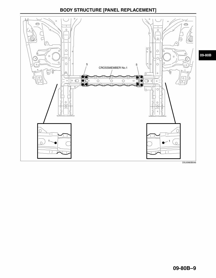
End Of SieBM: CROSSMEMBER No.1CROSSMEMBER No.1 REMOVAL[PANEL REPLACEMENT]
id098008603500
1. Remove the crossmember No.1.
1
2
2
2
FRONT BUMPER BRACKET
D5U0980B044
3426-1U-06F(09-80B).fm 8 ページ 2006年6月20日 火曜日 午後7時32分
BODY STRUCTURE [PANEL REPLACEMENT]
09-80B–9
09-80B
55CROSSMEMBER No.1
11
D5U0980B046
3426-1U-06F(09-80B).fm 9 ページ 2006年6月20日 火曜日 午後7時32分

BODY STRUCTURE [PANEL REPLACEMENT]
09-80B–10
2. Remove the crossmember No.1 side bracket.
End Of Sie
7
6
7
7
CROSSMEMBER No.1 SIDE BRACKET
CROSSMEMBER No.1 SIDE BRACKET
D5U0980B052
3426-1U-06F(09-80B).fm 10 ページ 2006年6月20日 火曜日 午後7時32分

BODY STRUCTURE [PANEL REPLACEMENT]
09-80B–11
09-80B
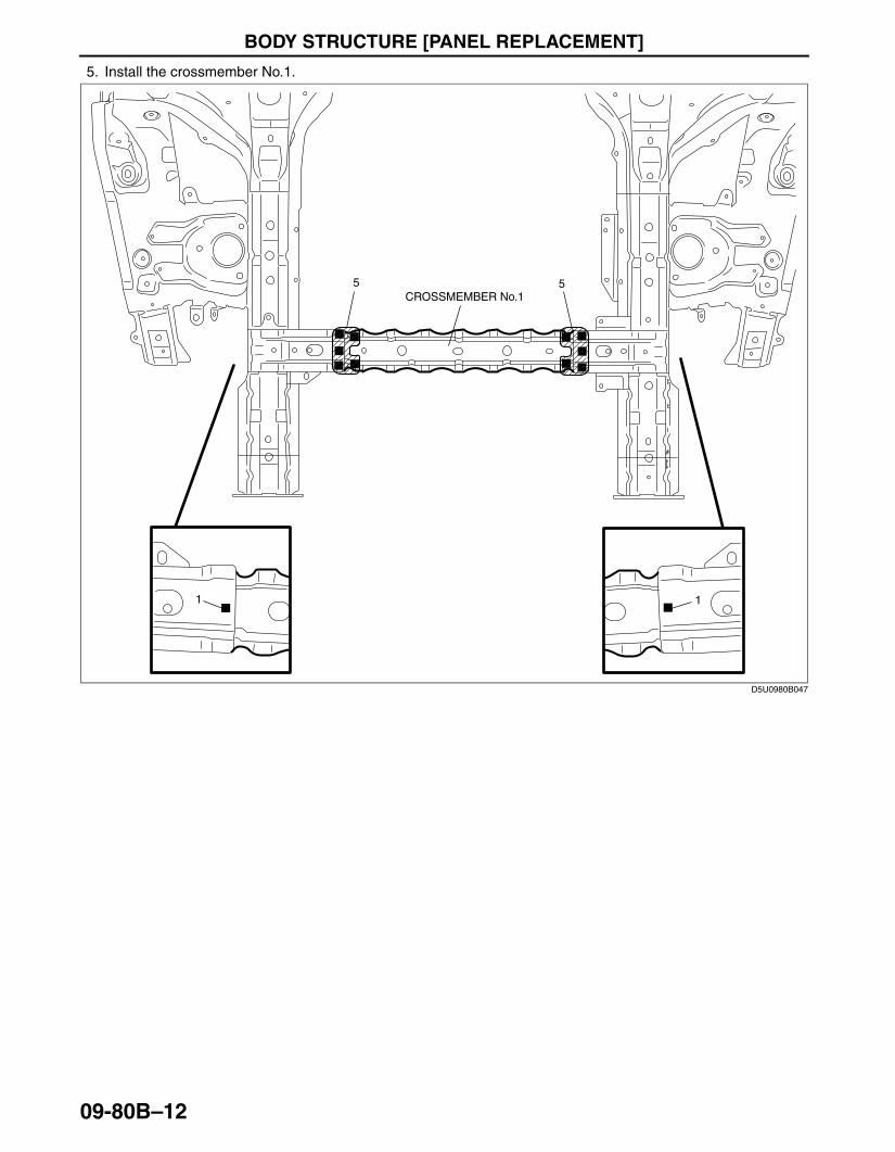
CROSSMEMBER No.1 INSTALLATION[PANEL REPLACEMENT]id098008603600
1. When installing new parts, measure and adjust the body as necessary to conform with standard dimensions.2. Drill holes for plug welds before installing new parts.3. After temporarily installing new parts, make sure the related parts fit properly.4. Install the crossmember No.1 side bracket.
7
6
7
7
CROSSMEMBER No.1 SIDE BRACKET
CROSSMEMBER No.1 SIDE BRACKET
D5U0980B053
3426-1U-06F(09-80B).fm 11 ページ 2006年6月20日 火曜日 午後7時32分
BODY STRUCTURE [PANEL REPLACEMENT]
09-80B–12
5. Install the crossmember No.1.
End Of SieBM: COWL SIDE REINFORCEMENT
55CROSSMEMBER No.1
11
D5U0980B047
3426-1U-06F(09-80B).fm 12 ページ 2006年6月20日 火曜日 午後7時32分

BODY STRUCTURE [PANEL REPLACEMENT]
09-80B–13
09-80B
COWL SIDE REINFORCEMENT REMOVAL[PANEL REPLACEMENT]id098008741700
1. Remove the cowl side reinforcement.
Caution• Be careful not to damage the windshield when drilling the 2 locations indicated by (A).
End Of Sie
11
4
(A)2
1
3
1
3
7
4
COWL SIDE REINFORCEMENT
5
D5U0980B048
3426-1U-06F(09-80B).fm 13 ページ 2006年6月20日 火曜日 午後7時32分
BODY STRUCTURE [PANEL REPLACEMENT]
09-80B–14
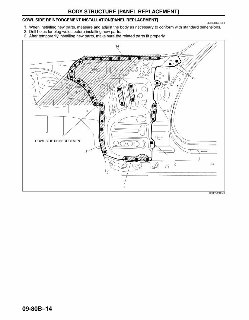
COWL SIDE REINFORCEMENT INSTALLATION[PANEL REPLACEMENT]id098008741800
1. When installing new parts, measure and adjust the body as necessary to conform with standard dimensions.2. Drill holes for plug welds before installing new parts.3. After temporarily installing new parts, make sure the related parts fit properly.
End Of SieBM: APRON REINFORCEMENT
14
4
2
1
3
1
3
7
4
COWL SIDE REINFORCEMENT
5
D5U0980B049
3426-1U-06F(09-80B).fm 14 ページ 2006年6月20日 火曜日 午後7時32分
BODY STRUCTURE [PANEL REPLACEMENT]
09-80B–15
09-80B
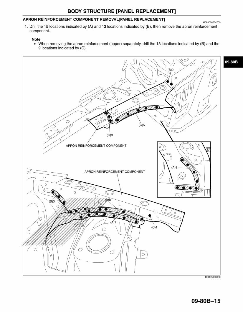
APRON REINFORCEMENT COMPONENT REMOVAL[PANEL REPLACEMENT]id098008604700
1. Drill the 15 locations indicated by (A) and 13 locations indicated by (B), then remove the apron reinforcement component.
Note• When removing the apron reinforcement (upper) separately, drill the 13 locations indicated by (B) and the
9 locations indicated by (C).
End Of Sie
(C)3
(B)3
(B)2
(B)8
(C)1
(C)5
APRON REINFORCEMENT COMPONENT
APRON REINFORCEMENT COMPONENT
(A)7
(A)8
D5U0980B050
3426-1U-06F(09-80B).fm 15 ページ 2006年6月20日 火曜日 午後7時32分

BODY STRUCTURE [PANEL REPLACEMENT]
09-80B–16
APRON REINFORCEMENT COMPONENT INSTALLATION[PANEL REPLACEMENT]id098008604800
1. When installing new parts, measure and adjust the body as necessary to conform with standard dimensions.2. Drill holes for plug welds before installing new parts.3. After temporarily installing new parts, make sure the related parts fit properly.
End Of Sie
3
2
8
APRON REINFORCEMENT COMPONENT
APRON REINFORCEMENT COMPONENT
7
8
D5U0980B051
3426-1U-06F(09-80B).fm 16 ページ 2006年6月20日 火曜日 午後7時32分
BODY STRUCTURE [PANEL REPLACEMENT]
09-80B–17
09-80B
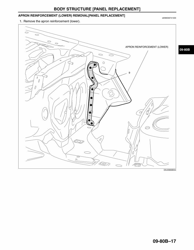
APRON REINFORCEMENT (LOWER) REMOVAL[PANEL REPLACEMENT]id098008741300
1. Remove the apron reinforcement (lower).
End Of Sie
9
APRON REINFORCEMENT (LOWER)
D5U0980B054
3426-1U-06F(09-80B).fm 17 ページ 2006年6月20日 火曜日 午後7時32分
BODY STRUCTURE [PANEL REPLACEMENT]
09-80B–18
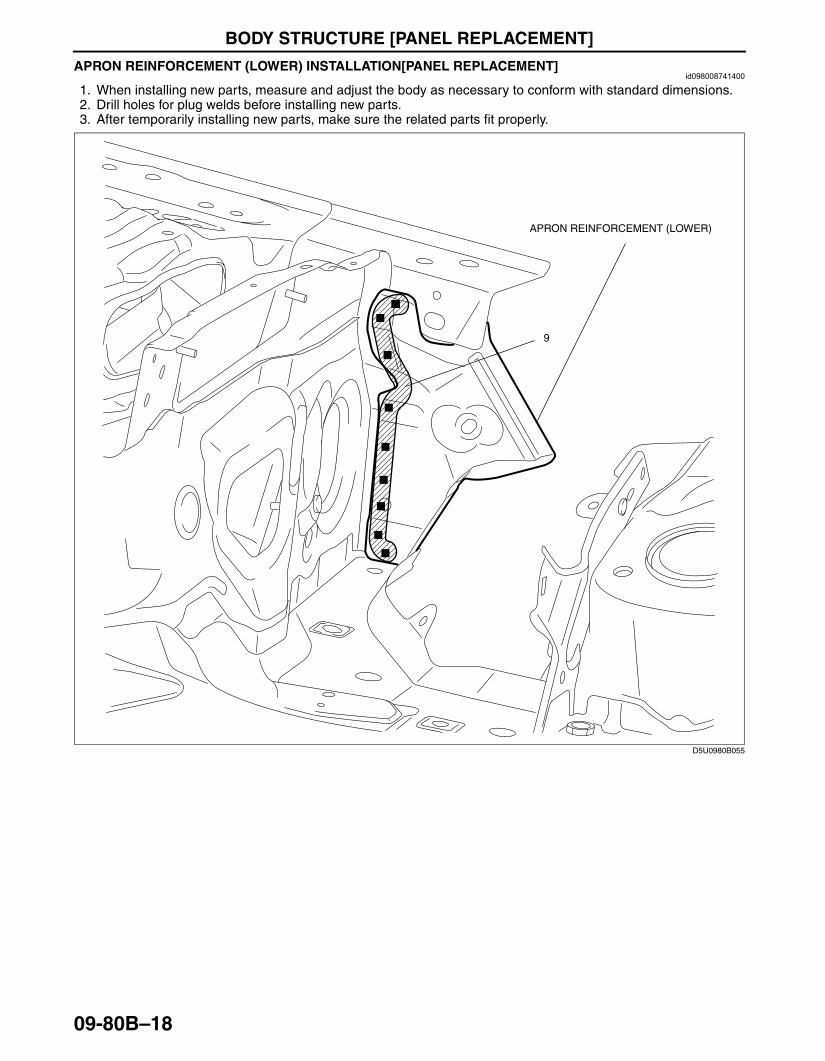
APRON REINFORCEMENT (LOWER) INSTALLATION[PANEL REPLACEMENT]id098008741400
1. When installing new parts, measure and adjust the body as necessary to conform with standard dimensions.2. Drill holes for plug welds before installing new parts.3. After temporarily installing new parts, make sure the related parts fit properly.
End Of SieBM: FRONT SIDE FRAME
9
APRON REINFORCEMENT (LOWER)
D5U0980B055
3426-1U-06F(09-80B).fm 18 ページ 2006年6月20日 火曜日 午後7時32分
BODY STRUCTURE [PANEL REPLACEMENT]
09-80B–19
09-80B
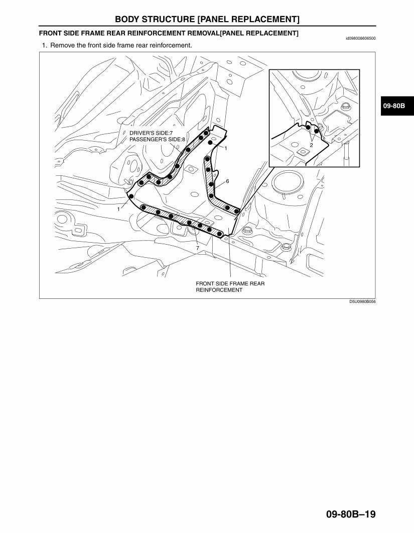
FRONT SIDE FRAME REAR REINFORCEMENT REMOVAL[PANEL REPLACEMENT]id098008606500
1. Remove the front side frame rear reinforcement.
End Of Sie
2
1
1
7
6
FRONT SIDE FRAME REAR REINFORCEMENT
DRIVER'S SIDE:7 PASSENGER'S SIDE:8
D5U0980B056
3426-1U-06F(09-80B).fm 19 ページ 2006年6月20日 火曜日 午後7時32分
BODY STRUCTURE [PANEL REPLACEMENT]
09-80B–20
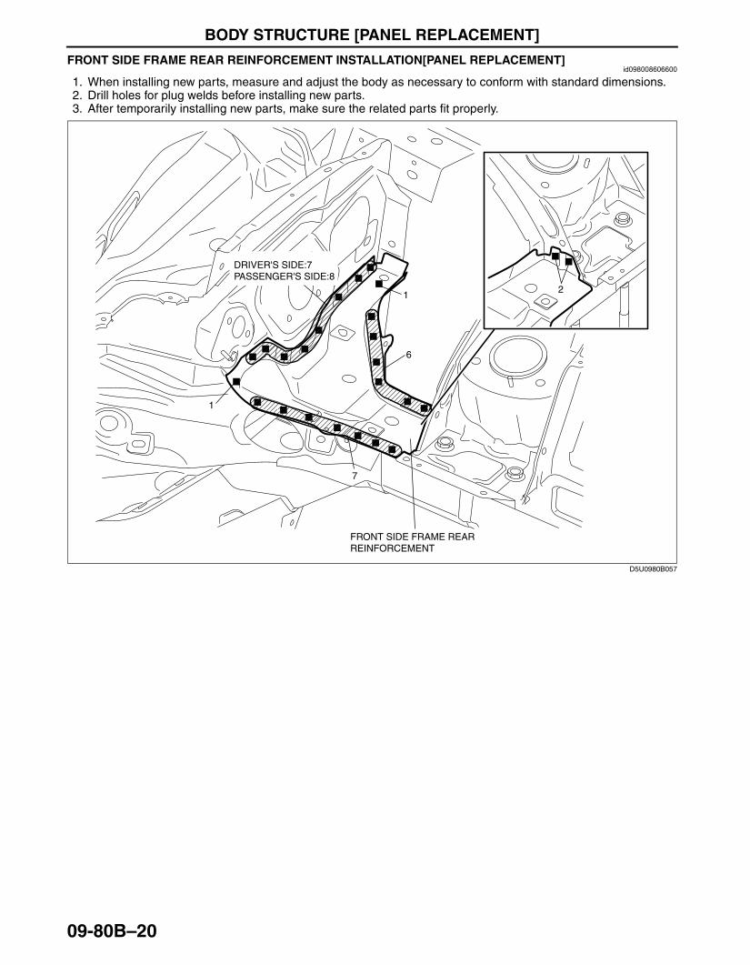
FRONT SIDE FRAME REAR REINFORCEMENT INSTALLATION[PANEL REPLACEMENT]id098008606600
1. When installing new parts, measure and adjust the body as necessary to conform with standard dimensions.2. Drill holes for plug welds before installing new parts.3. After temporarily installing new parts, make sure the related parts fit properly.
End Of Sie
2
1
1
7
6
DRIVER'S SIDE:7 PASSENGER'S SIDE:8
FRONT SIDE FRAME REAR REINFORCEMENT
D5U0980B057
3426-1U-06F(09-80B).fm 20 ページ 2006年6月20日 火曜日 午後7時32分
BODY STRUCTURE [PANEL REPLACEMENT]
09-80B–21
09-80B
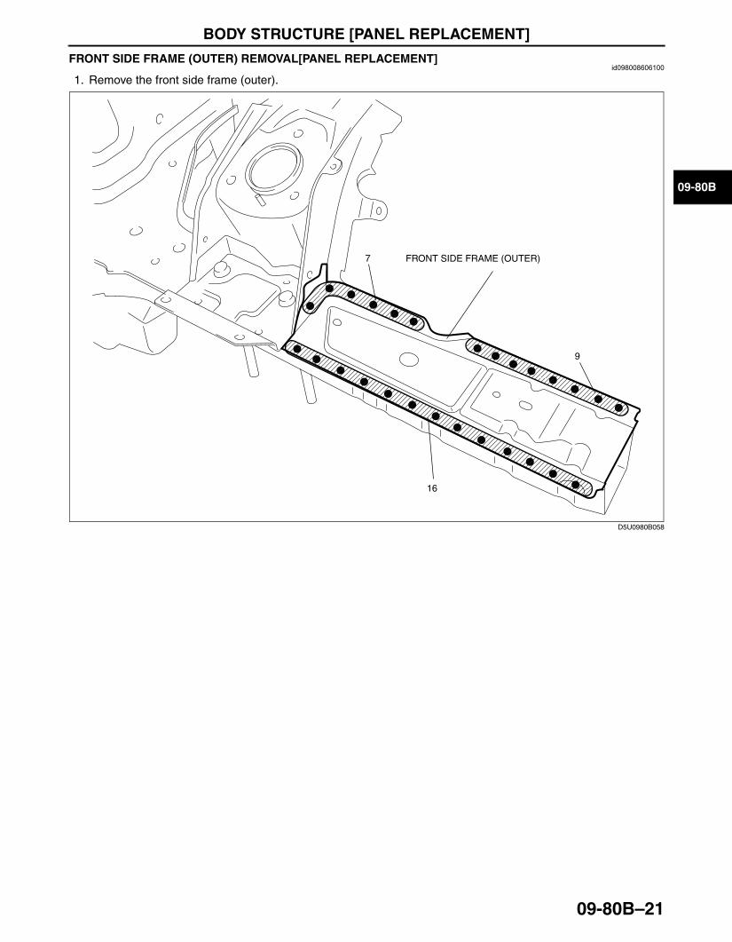
FRONT SIDE FRAME (OUTER) REMOVAL[PANEL REPLACEMENT]id098008606100
1. Remove the front side frame (outer).
End Of Sie
9
16
7 FRONT SIDE FRAME (OUTER)
D5U0980B058
3426-1U-06F(09-80B).fm 21 ページ 2006年6月20日 火曜日 午後7時32分

BODY STRUCTURE [PANEL REPLACEMENT]
09-80B–22
FRONT SIDE FRAME (OUTER) INSTALLATION[PANEL REPLACEMENT]id098008606200
1. When installing new parts, measure and adjust the body as necessary to conform with standard dimensions.2. Drill holes for plug welds before installing new parts.3. After temporarily installing new parts, make sure the related parts fit properly.
End Of Sie
9
16
FRONT SIDE FRAME (OUTER)7
D5U0980B059
3426-1U-06F(09-80B).fm 22 ページ 2006年6月20日 火曜日 午後7時32分
BODY STRUCTURE [PANEL REPLACEMENT]
09-80B–23
09-80B
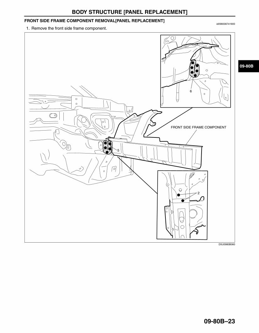
FRONT SIDE FRAME COMPONENT REMOVAL[PANEL REPLACEMENT]id098008741900
1. Remove the front side frame component.
End Of Sie
2
5
6
FRONT SIDE FRAME COMPONENT
D5U0980B060
3426-1U-06F(09-80B).fm 23 ページ 2006年6月20日 火曜日 午後7時32分
BODY STRUCTURE [PANEL REPLACEMENT]
09-80B–24
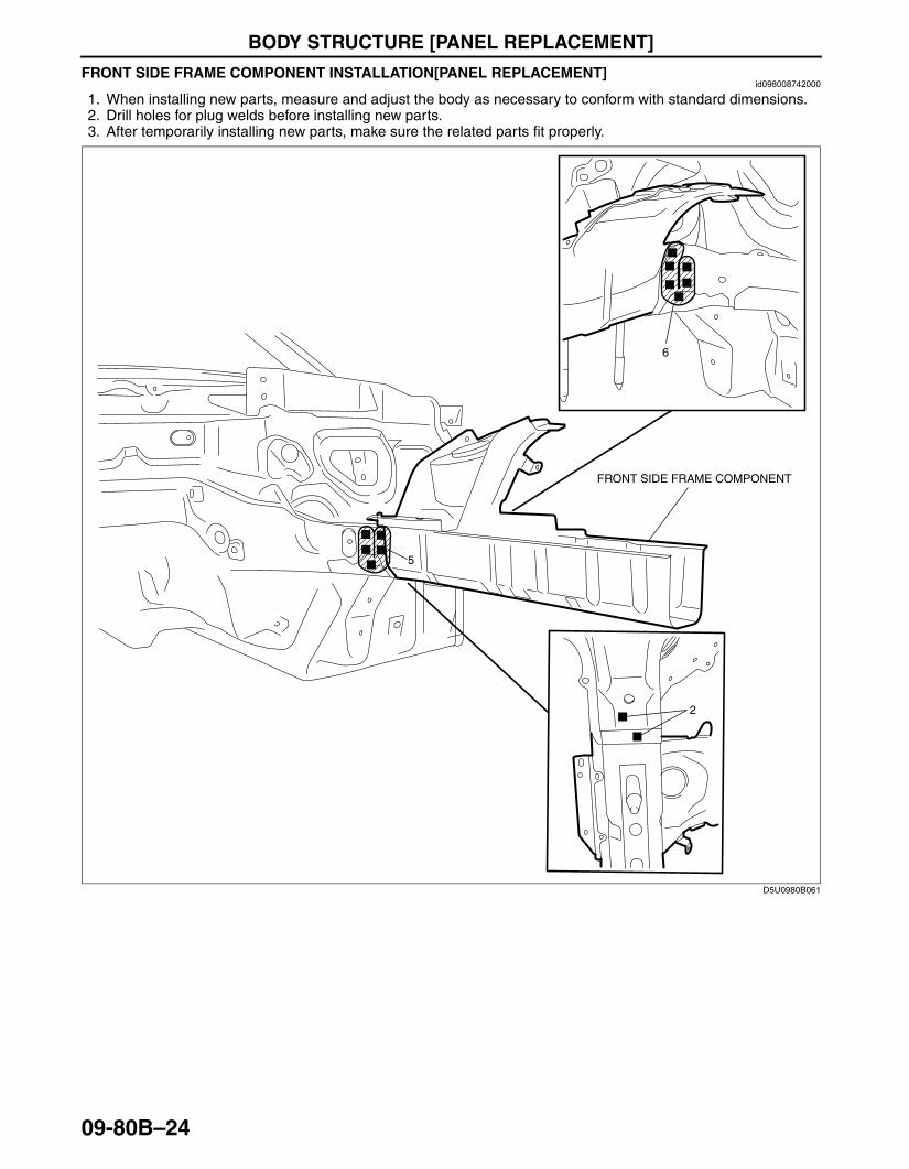
FRONT SIDE FRAME COMPONENT INSTALLATION[PANEL REPLACEMENT]id098008742000
1. When installing new parts, measure and adjust the body as necessary to conform with standard dimensions.2. Drill holes for plug welds before installing new parts.3. After temporarily installing new parts, make sure the related parts fit properly.
End Of Sie
2
5
6
FRONT SIDE FRAME COMPONENT
D5U0980B061
3426-1U-06F(09-80B).fm 24 ページ 2006年6月20日 火曜日 午後7時32分

BODY STRUCTURE [PANEL REPLACEMENT]
09-80B–25
09-80B
FRONT SIDE FRAME (PARTIAL CUTTING) REMOVAL[PANEL REPLACEMENT]id098008742100
1. Rough cut and remove the damaged part of the front side frame.
End Of Sie
45mm
70mm{2.76in}
{1.77in}
FRONT SIDE FRAME
ROUGH CUT LOCATION
CUT-AND-JOIN LOCATION
D5U0980B068
3426-1U-06F(09-80B).fm 25 ページ 2006年6月20日 火曜日 午後7時32分
BODY STRUCTURE [PANEL REPLACEMENT]
09-80B–26
FRONT SIDE FRAME (PARTIAL CUTTING) INSTALLATION[PANEL REPLACEMENT]id098008742200
Caution• The cut-and-joint area indicates the maximum size range of the installation position.
1. Make a reinforcement panel using the material from the front side frame.2. To cut and join the new and existing parts, cut the new part at the specified location shown in the figure, and
chamfer the joint surfaces of the new and existing parts.3. When installing the new parts, trial-fit new and existing parts, and then measure and adjust the body to conform
with standard dimensions.4. After temporarily installing new parts, make sure the related parts fit properly.
3426-1U-06F(09-80B).fm 26 ページ 2006年6月20日 火曜日 午後7時32分
BODY STRUCTURE [PANEL REPLACEMENT]
09-80B–27
09-80B
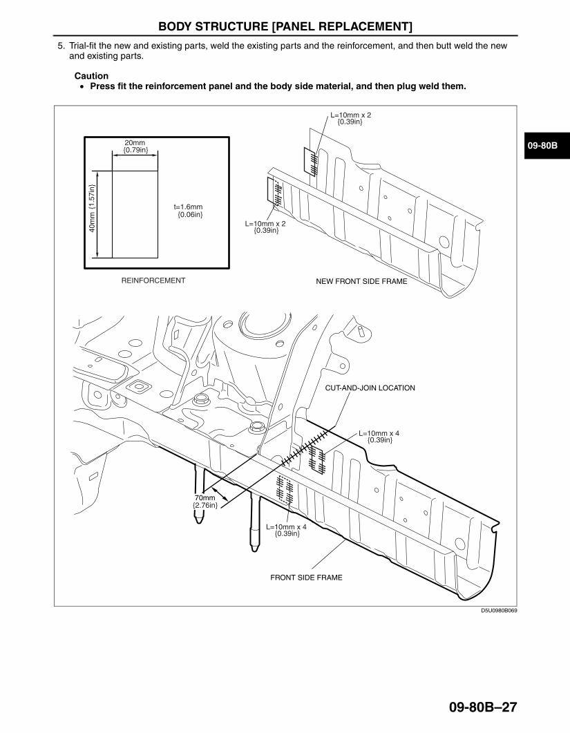
5. Trial-fit the new and existing parts, weld the existing parts and the reinforcement, and then butt weld the new and existing parts.
Caution• Press fit the reinforcement panel and the body side material, and then plug weld them.
End Of Sie
70mm
40m
m{1
.57i
n}
REINFORCEMENT
t=1.6mm{0.06in}
20mm{0.79in}
FRONT SIDE FRAME
CUT-AND-JOIN LOCATION
NEW FRONT SIDE FRAME
{2.76in}
L=10mm x 2{0.39in}
L=10mm x 2{0.39in}
L=10mm x 4{0.39in}
L=10mm x 4{0.39in}
D5U0980B069
3426-1U-06F(09-80B).fm 27 ページ 2006年6月20日 火曜日 午後7時32分

BODY STRUCTURE [PANEL REPLACEMENT]
09-80B–28
FRONT FRAME COMPONENT (FRONT) REMOVAL[PANEL REPLACEMENT]id098008606300
1. Drill the 2 locations indicated by (A).
Note• To prevent damage to the front side frame rear reinforcement, grind it using a belt grinder from the front
side.
2. Remove the front frame component (front).
12
2
5
6
FRONT FRAME COMPONENT (FRONT)
(A)2
D5U0980B140
3426-1U-06F(09-80B).fm 28 ページ 2006年6月20日 火曜日 午後7時32分
BODY STRUCTURE [PANEL REPLACEMENT]
09-80B–29
09-80B
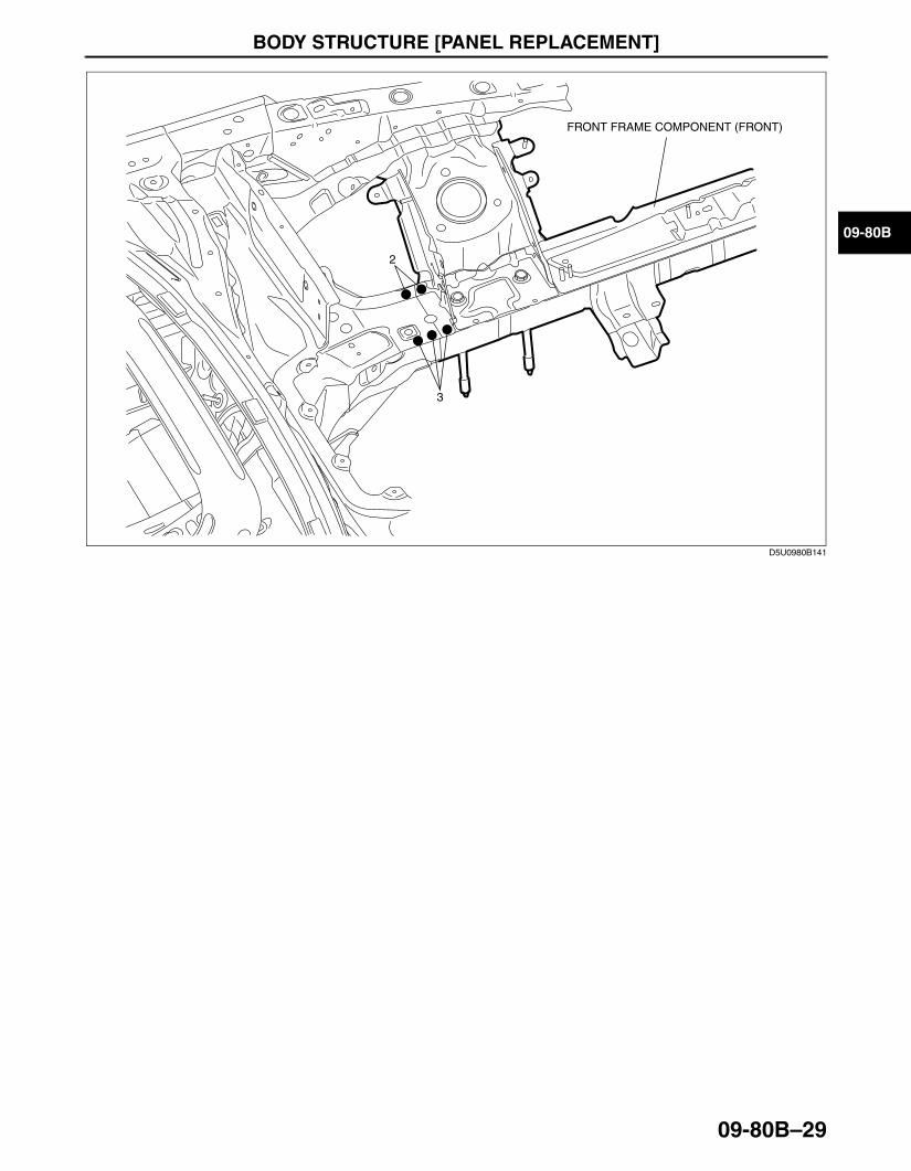
End Of Sie
2
3
FRONT FRAME COMPONENT (FRONT)
D5U0980B141
3426-1U-06F(09-80B).fm 29 ページ 2006年6月20日 火曜日 午後7時32分
BODY STRUCTURE [PANEL REPLACEMENT]
09-80B–30
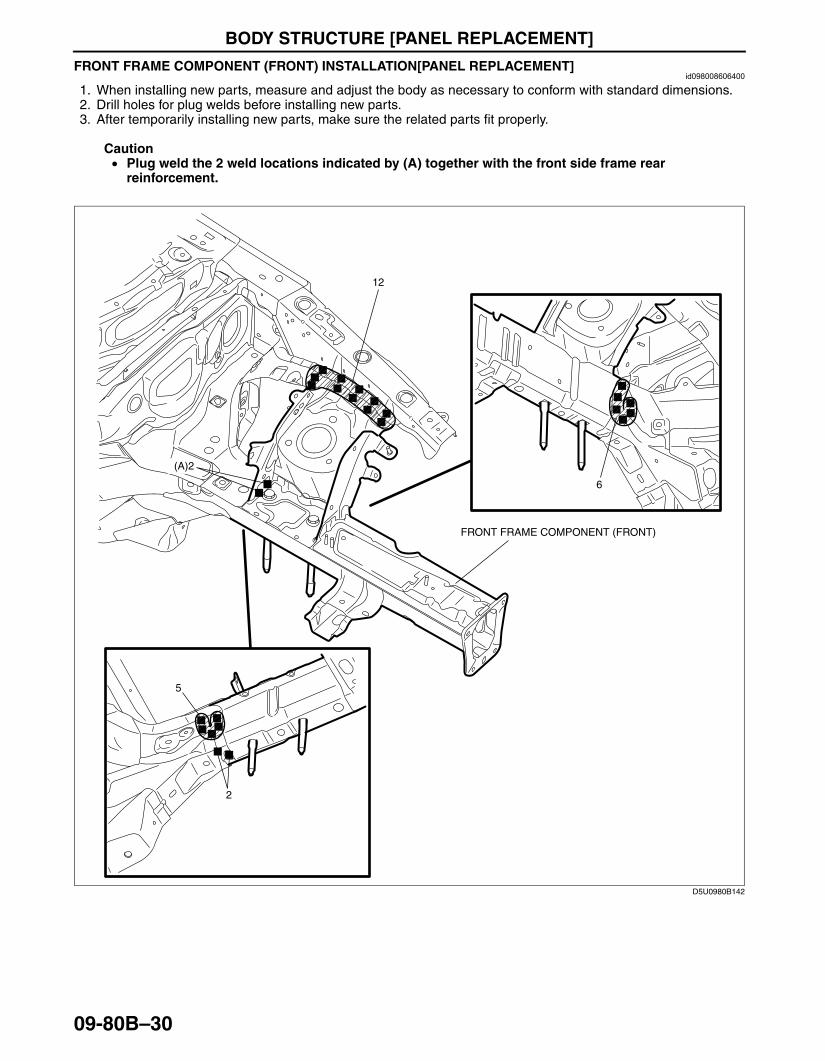
FRONT FRAME COMPONENT (FRONT) INSTALLATION[PANEL REPLACEMENT]id098008606400
1. When installing new parts, measure and adjust the body as necessary to conform with standard dimensions.2. Drill holes for plug welds before installing new parts.3. After temporarily installing new parts, make sure the related parts fit properly.
Caution• Plug weld the 2 weld locations indicated by (A) together with the front side frame rear
reinforcement.
12
2
5
6
FRONT FRAME COMPONENT (FRONT)
(A)2
D5U0980B142
3426-1U-06F(09-80B).fm 30 ページ 2006年6月20日 火曜日 午後7時32分

BODY STRUCTURE [PANEL REPLACEMENT]
09-80B–31
09-80B
End Of Sie
2
3
FRONT FRAME COMPONENT (FRONT)
D5U0980B143
3426-1U-06F(09-80B).fm 31 ページ 2006年6月20日 火曜日 午後7時32分

BODY STRUCTURE [PANEL REPLACEMENT]
09-80B–32
FRONT FRAME COMPONENT REMOVAL[PANEL REPLACEMENT]id098008616400
1. Drill the 2 location indicated by (A) from the interior, as they cannot be seen from the outer side.2. Remove the front frame component.
6
(A)2
DRIVER'S SIDE:7 PASSENGER'S SIDE:8
FRONT FRAME COMPONENT
D5U0980B062
3426-1U-06F(09-80B).fm 32 ページ 2006年6月20日 火曜日 午後7時32分

BODY STRUCTURE [PANEL REPLACEMENT]
09-80B–33
09-80B
End Of Sie
10
9
1
1
3
1
4
912
3
55
4
2
FRONT FRAME COMPONENT
FRONT FRAME COMPONENT
D5U0980B063
3426-1U-06F(09-80B).fm 33 ページ 2006年6月20日 火曜日 午後7時32分
BODY STRUCTURE [PANEL REPLACEMENT]
09-80B–34
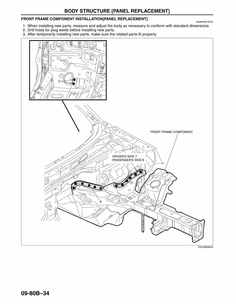
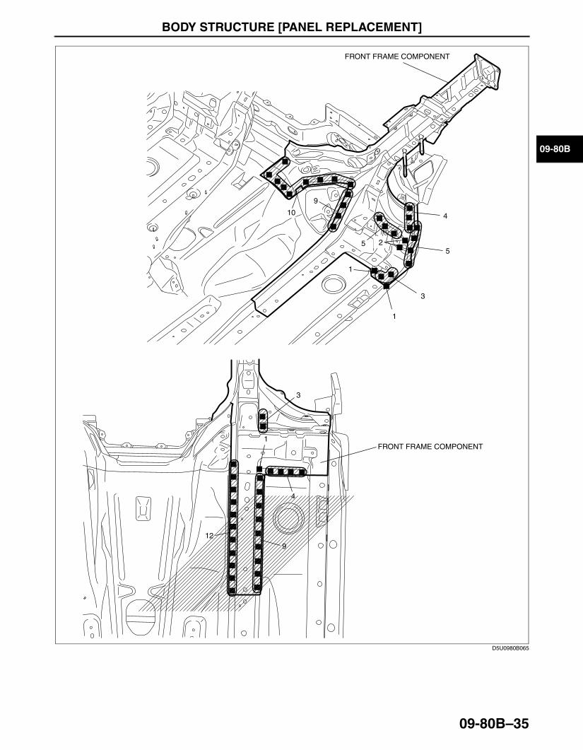
FRONT FRAME COMPONENT INSTALLATION[PANEL REPLACEMENT]id098008616500
1. When installing new parts, measure and adjust the body as necessary to conform with standard dimensions.2. Drill holes for plug welds before installing new parts.3. After temporarily installing new parts, make sure the related parts fit properly.
6
2
DRIVER'S SIDE:7 PASSENGER'S SIDE:8
FRONT FRAME COMPONENT
D5U0980B064
3426-1U-06F(09-80B).fm 34 ページ 2006年6月20日 火曜日 午後7時32分
BODY STRUCTURE [PANEL REPLACEMENT]
09-80B–35
09-80B
End Of SieBM: TORQUE BOX
10
9
1
1
3
1
4
912
3
55
4
2
FRONT FRAME COMPONENT
FRONT FRAME COMPONENT
D5U0980B065
3426-1U-06F(09-80B).fm 35 ページ 2006年6月20日 火曜日 午後7時32分
BODY STRUCTURE [PANEL REPLACEMENT]
09-80B–36
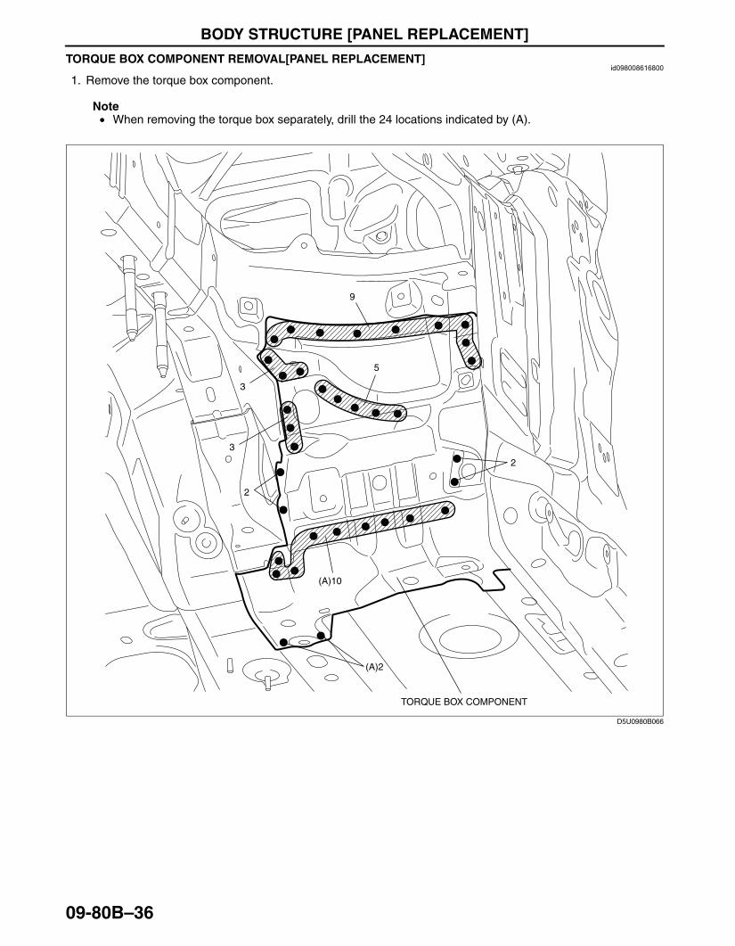
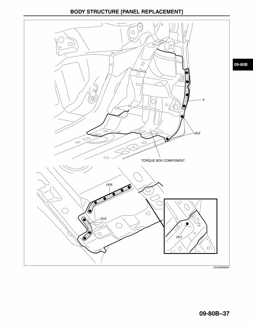
TORQUE BOX COMPONENT REMOVAL[PANEL REPLACEMENT]id098008616800
1. Remove the torque box component.
Note• When removing the torque box separately, drill the 24 locations indicated by (A).
3
3
2
2
5
9
(A)10
(A)2
TORQUE BOX COMPONENT
D5U0980B066
3426-1U-06F(09-80B).fm 36 ページ 2006年6月20日 火曜日 午後7時32分
BODY STRUCTURE [PANEL REPLACEMENT]
09-80B–37
09-80B
End Of Sie
4
(A)2
(A)6
(A)3
(A)1
TORQUE BOX COMPONENT
D5U0980B067
3426-1U-06F(09-80B).fm 37 ページ 2006年6月20日 火曜日 午後7時32分

BODY STRUCTURE [PANEL REPLACEMENT]
09-80B–38
TORQUE BOX COMPONENT INSTALLATION[PANEL REPLACEMENT]id098008616900
1. When installing new parts, measure and adjust the body as necessary to conform with standard dimensions.2. Drill holes for plug welds before installing new parts.3. After temporarily installing new parts, make sure the related parts fit properly.
3
3
2
2
5
9
10
2
TORQUE BOX COMPONENT
D5U0980B070
3426-1U-06F(09-80B).fm 38 ページ 2006年6月20日 火曜日 午後7時32分

BODY STRUCTURE [PANEL REPLACEMENT]
09-80B–39
09-80B
End Of SieBM: FRONT PILLAR
4
2
6
3
1
TORQUE BOX COMPONENT
D5U0980B071
3426-1U-06F(09-80B).fm 39 ページ 2006年6月20日 火曜日 午後7時32分
BODY STRUCTURE [PANEL REPLACEMENT]
09-80B–40
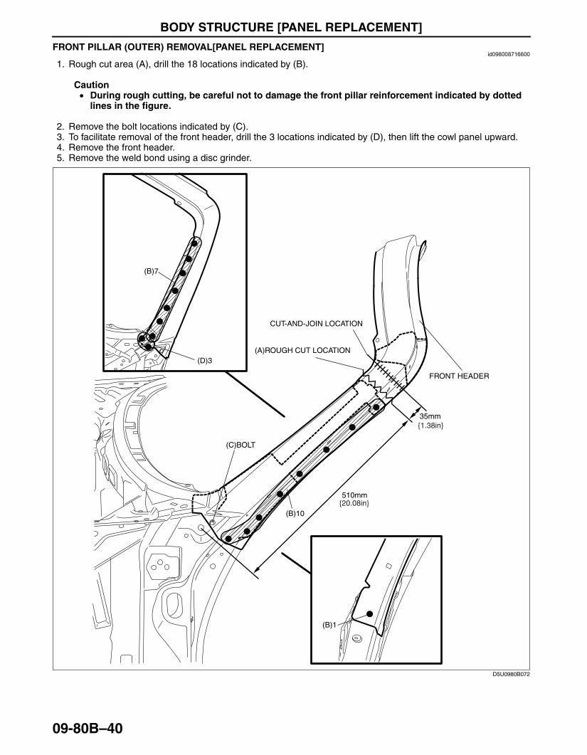
FRONT PILLAR (OUTER) REMOVAL[PANEL REPLACEMENT]id098008716600
1. Rough cut area (A), drill the 18 locations indicated by (B).
Caution• During rough cutting, be careful not to damage the front pillar reinforcement indicated by dotted
lines in the figure.
2. Remove the bolt locations indicated by (C).3. To facilitate removal of the front header, drill the 3 locations indicated by (D), then lift the cowl panel upward.4. Remove the front header.5. Remove the weld bond using a disc grinder.
End Of Sie
(B)10
35mm
510mm
FRONT HEADER
(B)7
(D)3
(B)1
(C)BOLT
{20.08in}
{1.38in}
(A)ROUGH CUT LOCATION
CUT-AND-JOIN LOCATION
D5U0980B072
3426-1U-06F(09-80B).fm 40 ページ 2006年6月20日 火曜日 午後7時32分
BODY STRUCTURE [PANEL REPLACEMENT]
09-80B–41
09-80B
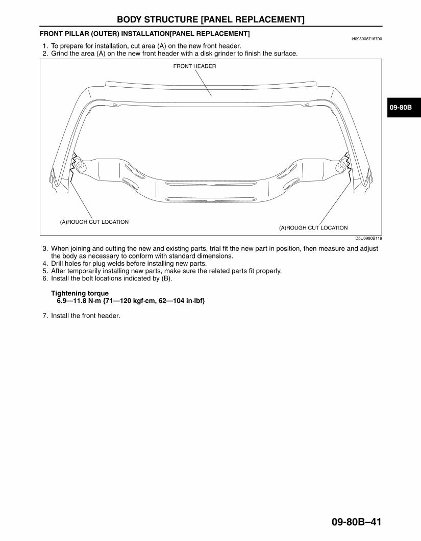
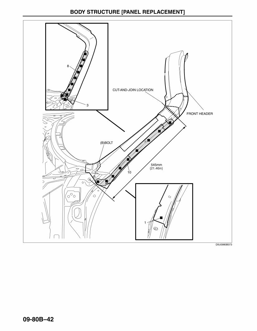
FRONT PILLAR (OUTER) INSTALLATION[PANEL REPLACEMENT]id098008716700
1. To prepare for installation, cut area (A) on the new front header.2. Grind the area (A) on the new front header with a disk grinder to finish the surface.
3. When joining and cutting the new and existing parts, trial fit the new part in position, then measure and adjust the body as necessary to conform with standard dimensions.
4. Drill holes for plug welds before installing new parts.5. After temporarily installing new parts, make sure the related parts fit properly.6. Install the bolt locations indicated by (B).
Tightening torque6.9—11.8 N·m {71—120 kgf·cm, 62—104 in·lbf}
7. Install the front header.
FRONT HEADER
(A)ROUGH CUT LOCATION(A)ROUGH CUT LOCATION
D5U0980B119
3426-1U-06F(09-80B).fm 41 ページ 2006年6月20日 火曜日 午後7時32分
BODY STRUCTURE [PANEL REPLACEMENT]
09-80B–42
End Of Sie
10
545mm
FRONT HEADER
8
3
1
(B)BOLT
{21.46in}
CUT-AND-JOIN LOCATION
D5U0980B073
3426-1U-06F(09-80B).fm 42 ページ 2006年6月20日 火曜日 午後7時32分
BODY STRUCTURE [PANEL REPLACEMENT]
09-80B–43
09-80B
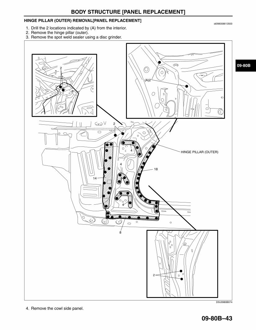
HINGE PILLAR (OUTER) REMOVAL[PANEL REPLACEMENT]id098008613500
1. Drill the 2 locations indicated by (A) from the interior.2. Remove the hinge pillar (outer).3. Remove the spot weld sealer using a disc grinder.
4. Remove the cowl side panel.
2
2
2
(A)2
14
4
4
18
4
8
HINGE PILLAR (OUTER)
D5U0980B074
3426-1U-06F(09-80B).fm 43 ページ 2006年6月20日 火曜日 午後7時32分
BODY STRUCTURE [PANEL REPLACEMENT]
09-80B–44
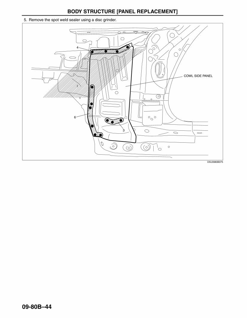
5. Remove the spot weld sealer using a disc grinder.
6
4
3
COWL SIDE PANEL
D5U0980B075
3426-1U-06F(09-80B).fm 44 ページ 2006年6月20日 火曜日 午後7時32分

BODY STRUCTURE [PANEL REPLACEMENT]
09-80B–45
09-80B
6. Remove the front pillar reinforcement.
2
2
FRONT PILLAR REINFORCEMENT
D5U0980B076
3426-1U-06F(09-80B).fm 45 ページ 2006年6月20日 火曜日 午後7時32分

BODY STRUCTURE [PANEL REPLACEMENT]
09-80B–46
7. Remove the front pillar (inner).
End Of Sie
2
5
2
FRONT PILLAR (INNER)
D5U0980B077
3426-1U-06F(09-80B).fm 46 ページ 2006年6月20日 火曜日 午後7時32分
BODY STRUCTURE [PANEL REPLACEMENT]
09-80B–47
09-80B
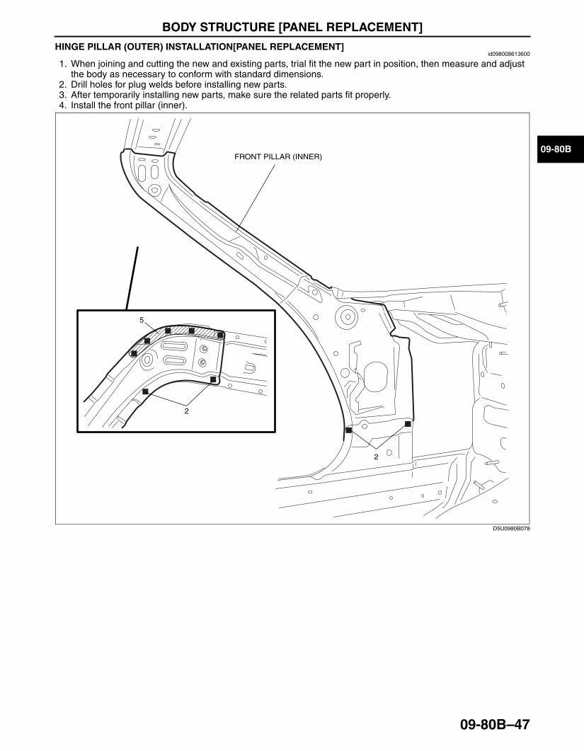
HINGE PILLAR (OUTER) INSTALLATION[PANEL REPLACEMENT]id098008613600
1. When joining and cutting the new and existing parts, trial fit the new part in position, then measure and adjust the body as necessary to conform with standard dimensions.
2. Drill holes for plug welds before installing new parts.3. After temporarily installing new parts, make sure the related parts fit properly.4. Install the front pillar (inner).
2
5
FRONT PILLAR (INNER)
2
D5U0980B078
3426-1U-06F(09-80B).fm 47 ページ 2006年6月20日 火曜日 午後7時32分
BODY STRUCTURE [PANEL REPLACEMENT]
09-80B–48
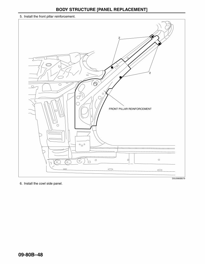
5. Install the front pillar reinforcement.
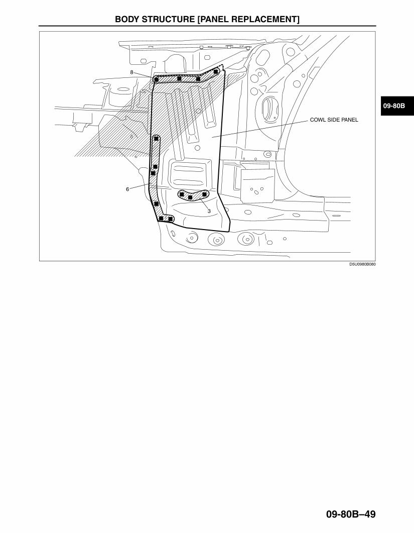
6. Install the cowl side panel.
FRONT PILLAR REINFORCEMENT
2
2
D5U0980B079
3426-1U-06F(09-80B).fm 48 ページ 2006年6月20日 火曜日 午後7時32分
BODY STRUCTURE [PANEL REPLACEMENT]
09-80B–49
09-80B
6
8
3
COWL SIDE PANEL
D5U0980B080
3426-1U-06F(09-80B).fm 49 ページ 2006年6月20日 火曜日 午後7時32分
BODY STRUCTURE [PANEL REPLACEMENT]
09-80B–50
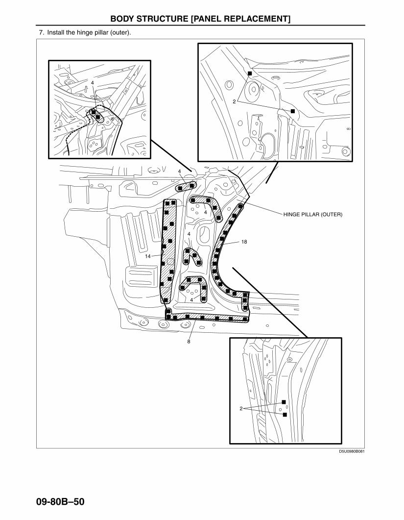
7. Install the hinge pillar (outer).
End Of SieBM: REAR FENDER PANEL
HINGE PILLAR (OUTER)
4
4
2
2
14
4
4
18
4
8
D5U0980B081
3426-1U-06F(09-80B).fm 50 ページ 2006年6月20日 火曜日 午後7時32分
BODY STRUCTURE [PANEL REPLACEMENT]
09-80B–51
09-80B
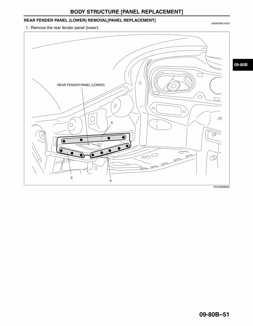
REAR FENDER PANEL (LOWER) REMOVAL[PANEL REPLACEMENT]id098008614300
1. Remove the rear fender panel (lower).
End Of Sie
REAR FENDER PANEL (LOWER)
5
4
3
D5U0980B083
3426-1U-06F(09-80B).fm 51 ページ 2006年6月20日 火曜日 午後7時32分
BODY STRUCTURE [PANEL REPLACEMENT]
09-80B–52
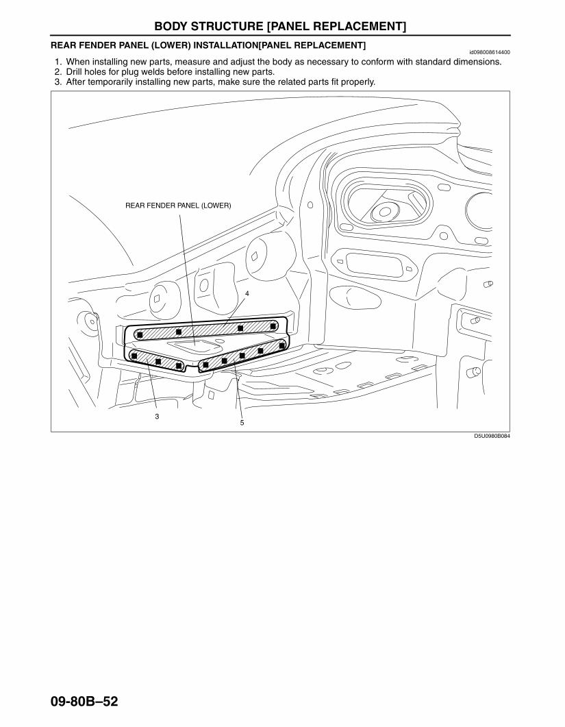
REAR FENDER PANEL (LOWER) INSTALLATION[PANEL REPLACEMENT]id098008614400
1. When installing new parts, measure and adjust the body as necessary to conform with standard dimensions.2. Drill holes for plug welds before installing new parts.3. After temporarily installing new parts, make sure the related parts fit properly.
End Of Sie
5
4
3
REAR FENDER PANEL (LOWER)
D5U0980B084
3426-1U-06F(09-80B).fm 52 ページ 2006年6月20日 火曜日 午後7時32分
BODY STRUCTURE [PANEL REPLACEMENT]
09-80B–53
09-80B
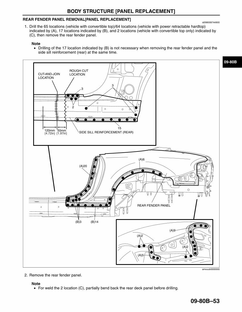
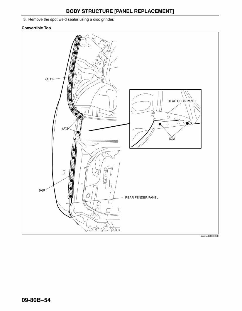
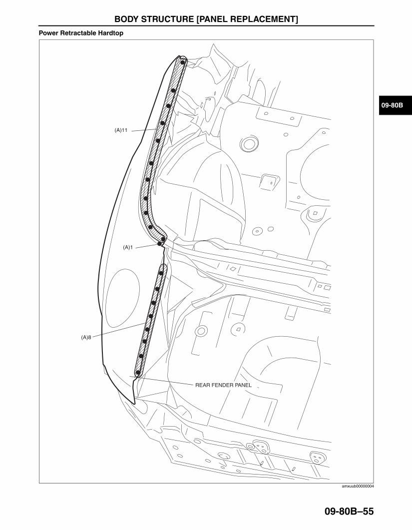
REAR FENDER PANEL REMOVAL[PANEL REPLACEMENT]id098008744900
1. Drill the 65 locations (vehicle with convertible top)/64 locations (vehicle with power retractable hardtop) indicated by (A), 17 locations indicated by (B), and 2 locations (vehicle with convertible top only) indicated by (C), then remove the rear fender panel.
Note• Drilling of the 17 location indicated by (B) is not necessary when removing the rear fender panel and the
side sill reinforcement (rear) at the same time.
2. Remove the rear fender panel.
Note• For weld the 2 location (C), partially bend back the rear deck panel before drilling.
REAR FENDER PANEL
(A)20
(B)14(B)3
(A)6
(A)9
(A)5
(A)2
(A)2
SIDE SILL REINFORCEMENT (REAR)
33
50mm120mm
2
ROUGH CUT LOCATION CUT-AND-JOIN
LOCATION
{4.72in} {1.97in}
15
amxuub0000000
3426-1U-06F(09-80B).fm 53 ページ 2006年6月20日 火曜日 午後7時32分
BODY STRUCTURE [PANEL REPLACEMENT]
09-80B–54
3. Remove the spot weld sealer using a disc grinder.
Convertible Top
(A)2
(A)11
(C)2
(A)8
REAR FENDER PANEL
REAR DECK PANEL
amxuub0000000
3426-1U-06F(09-80B).fm 54 ページ 2006年6月20日 火曜日 午後7時32分
BODY STRUCTURE [PANEL REPLACEMENT]
09-80B–55
09-80B
Power Retractable Hardtop
End Of Sie
(A)8
(A)1
(A)11
REAR FENDER PANEL
amxuub00000004
3426-1U-06F(09-80B).fm 55 ページ 2006年6月20日 火曜日 午後7時32分
BODY STRUCTURE [PANEL REPLACEMENT]
09-80B–56
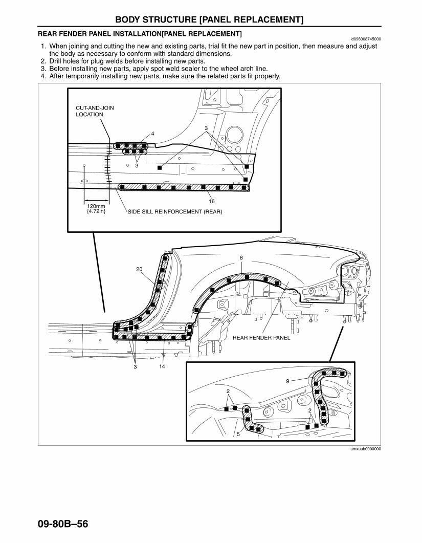
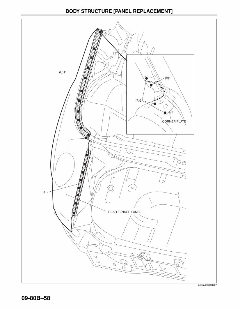
REAR FENDER PANEL INSTALLATION[PANEL REPLACEMENT]id098008745000
1. When joining and cutting the new and existing parts, trial fit the new part in position, then measure and adjust the body as necessary to conform with standard dimensions.
2. Drill holes for plug welds before installing new parts.3. Before installing new parts, apply spot weld sealer to the wheel arch line.4. After temporarily installing new parts, make sure the related parts fit properly.
20
143
8
9
5
2
2
REAR FENDER PANEL
SIDE SILL REINFORCEMENT (REAR)
43
120mm
3
CUT-AND-JOIN LOCATION
{4.72in}
16
amxuub0000000
3426-1U-06F(09-80B).fm 56 ページ 2006年6月20日 火曜日 午後7時32分
BODY STRUCTURE [PANEL REPLACEMENT]
09-80B–57
09-80B
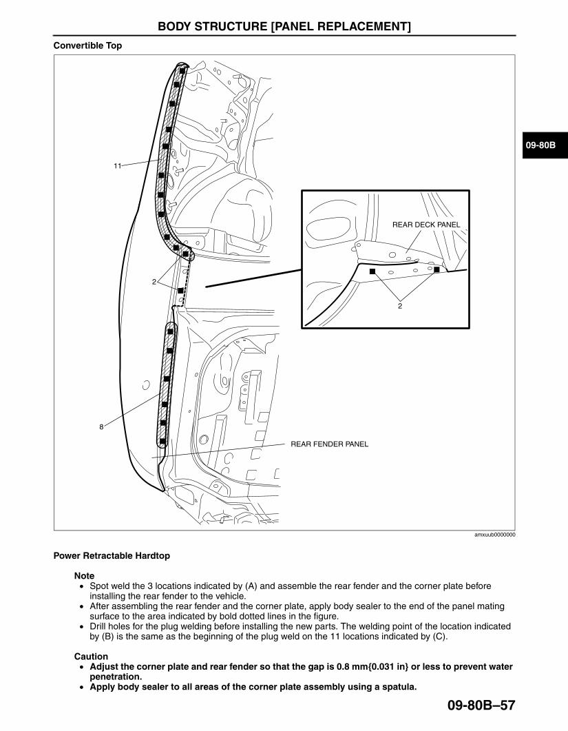
Convertible Top
Power Retractable Hardtop
Note• Spot weld the 3 locations indicated by (A) and assemble the rear fender and the corner plate before
installing the rear fender to the vehicle.• After assembling the rear fender and the corner plate, apply body sealer to the end of the panel mating
surface to the area indicated by bold dotted lines in the figure.• Drill holes for the plug welding before installing the new parts. The welding point of the location indicated
by (B) is the same as the beginning of the plug weld on the 11 locations indicated by (C).
Caution• Adjust the corner plate and rear fender so that the gap is 0.8 mm{0.031 in} or less to prevent water
penetration.• Apply body sealer to all areas of the corner plate assembly using a spatula.
2
11
2
8
REAR FENDER PANEL
REAR DECK PANEL
amxuub0000000
3426-1U-06F(09-80B).fm 57 ページ 2006年6月20日 火曜日 午後7時32分
BODY STRUCTURE [PANEL REPLACEMENT]
09-80B–58End Of Sie
8
1
(C)11
REAR FENDER PANEL
(A)3
(B)1
CORNER PLATE
amxuub00000007
3426-1U-06F(09-80B).fm 58 ページ 2006年6月20日 火曜日 午後7時32分

BODY STRUCTURE [PANEL REPLACEMENT]
09-80B–59
09-80B
BM: SIDE SILL PANELSIDE SILL REINFORCEMENT (FRONT) REMOVAL[PANEL REPLACEMENT]id098008616200
1. Rough cut and remove the damaged part of the side sill reinforcement (front).
Caution• During rough cutting, be careful not to damage the front pillar reinforcement indicated by dotted
lines in the figure.
Note• If the nut plate is not damaged, do not dispose of it, as it can be reinstalled. If it is damaged considerably,
replace it with a new one.
End Of Sie
22
83
120mm60mm
240mm
40mm
17
18
{9.45in}
{1.57in}
{4.72in}{2.36in}
ROUGH CUT LOCATION FOR HINGE PILLAR COMPONENT
NUT PLATE
ROUGH CUT LOCATION FOR SIDE SILL REINFORCEMENT (FRONT)
CUT-AND-JOIN LOCATION FOR HINGE PILLAR COMPONENT
CUT-AND-JOIN LOCATION FOR SIDE SILL REINFORCEMENT (FRONT)
D5U0980B093
3426-1U-06F(09-80B).fm 59 ページ 2006年6月20日 火曜日 午後7時32分
BODY STRUCTURE [PANEL REPLACEMENT]
09-80B–60
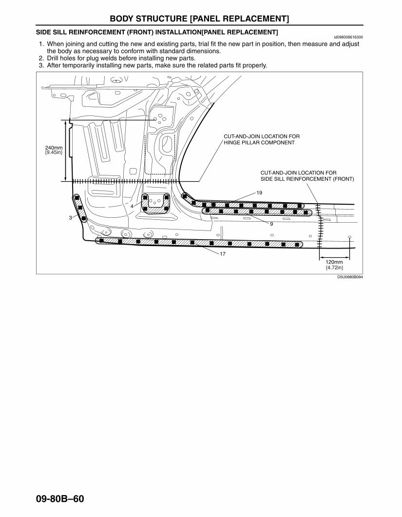
SIDE SILL REINFORCEMENT (FRONT) INSTALLATION[PANEL REPLACEMENT]id098008616300
1. When joining and cutting the new and existing parts, trial fit the new part in position, then measure and adjust the body as necessary to conform with standard dimensions.
2. Drill holes for plug welds before installing new parts.3. After temporarily installing new parts, make sure the related parts fit properly.
End Of Sie
4
93
120mm
240mm
17
19
CUT-AND-JOIN LOCATION FOR HINGE PILLAR COMPONENT
CUT-AND-JOIN LOCATION FORSIDE SILL REINFORCEMENT (FRONT)
{9.45in}
{4.72in}
D5U0980B094
3426-1U-06F(09-80B).fm 60 ページ 2006年6月20日 火曜日 午後7時32分
BODY STRUCTURE [PANEL REPLACEMENT]
09-80B–61
09-80B
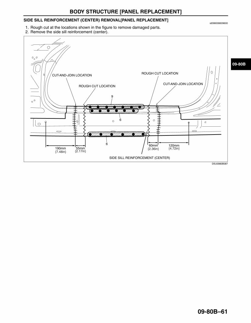
SIDE SILL REINFORCEMENT (CENTER) REMOVAL[PANEL REPLACEMENT]id098008609600
1. Rough cut at the locations shown in the figure to remove damaged parts.2. Remove the side sill reinforcement (center).
End Of Sie
9
6
6 120mm60mm190mm 55mm{7.48in} {2.17in}
{2.36in} {4.72in}
ROUGH CUT LOCATION
CUT-AND-JOIN LOCATION
CUT-AND-JOIN LOCATION
SIDE SILL REINFORCEMENT (CENTER)
ROUGH CUT LOCATION
D5U0980B087
3426-1U-06F(09-80B).fm 61 ページ 2006年6月20日 火曜日 午後7時32分
BODY STRUCTURE [PANEL REPLACEMENT]
09-80B–62
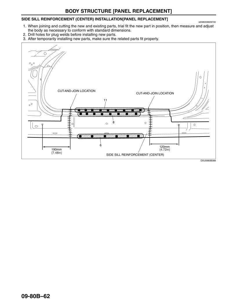
SIDE SILL REINFORCEMENT (CENTER) INSTALLATION[PANEL REPLACEMENT]id098008609700
1. When joining and cutting the new and existing parts, trial fit the new part in position, then measure and adjust the body as necessary to conform with standard dimensions.
2. Drill holes for plug welds before installing new parts.3. After temporarily installing new parts, make sure the related parts fit properly.
End Of Sie
11
8
6 120mm190mm{7.48in}
{4.72in}
CUT-AND-JOIN LOCATION
SIDE SILL REINFORCEMENT (CENTER)
CUT-AND-JOIN LOCATION
D5U0980B088
3426-1U-06F(09-80B).fm 62 ページ 2006年6月20日 火曜日 午後7時32分
BODY STRUCTURE [PANEL REPLACEMENT]
09-80B–63
09-80B
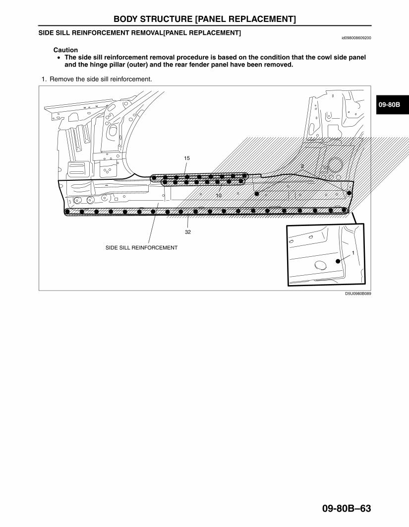
SIDE SILL REINFORCEMENT REMOVAL[PANEL REPLACEMENT]id098008609200
Caution• The side sill reinforcement removal procedure is based on the condition that the cowl side panel
and the hinge pillar (outer) and the rear fender panel have been removed.
1. Remove the side sill reinforcement.
End Of Sie
15
10
32
2
1SIDE SILL REINFORCEMENT
D5U0980B089
3426-1U-06F(09-80B).fm 63 ページ 2006年6月20日 火曜日 午後7時32分
BODY STRUCTURE [PANEL REPLACEMENT]
09-80B–64
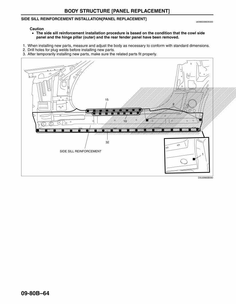
SIDE SILL REINFORCEMENT INSTALLATION[PANEL REPLACEMENT]id098008609300
Caution• The side sill reinforcement installation procedure is based on the condition that the cowl side
panel and the hinge pillar (outer) and the rear fender panel have been removed.
1. When installing new parts, measure and adjust the body as necessary to conform with standard dimensions.2. Drill holes for plug welds before installing new parts.3. After temporarily installing new parts, make sure the related parts fit properly.
End Of SieBM: REAR END PANEL
15
10
32
2
1SIDE SILL REINFORCEMENT
D5U0980B090
3426-1U-06F(09-80B).fm 64 ページ 2006年6月20日 火曜日 午後7時32分

BODY STRUCTURE [PANEL REPLACEMENT]
09-80B–65
09-80B
REAR END PANEL REMOVAL[PANEL REPLACEMENT]id098008744500
1. Remove the rear end panel.
End Of SieREAR END PANEL INSTALLATION[PANEL REPLACEMENT]
id098008744600
1. When installing new parts, measure and adjust the body as necessary to conform with standard dimensions.2. Drill holes for plug welds before installing new parts.3. After temporarily installing new parts, make sure the related parts fit properly.
End Of SieBM: REAR FENDER RAIN RAIL
3
5
15
5
12
REAR END PANEL
12
3
D5U0980B095
3
5
15
5
12 12
3
REAR END PANEL
D5U0980B096
3426-1U-06F(09-80B).fm 65 ページ 2006年6月20日 火曜日 午後7時32分

BODY STRUCTURE [PANEL REPLACEMENT]
09-80B–66
CORNER PLATE REMOVAL[PANEL REPLACEMENT]id098008610400
1. Remove the corner plate.
End Of SieCORNER PLATE INSTALLATION[PANEL REPLACEMENT]
id098008610500
1. When installing new parts, measure and adjust the body as necessary to conform with standard dimensions.2. Drill holes for plug welds before installing new parts.3. After temporarily installing new parts, make sure the related parts fit properly.
End Of Sie
2
14 5
CORNER PLATE
D5U0980B109
CORNER PLATE
2
14 5
D5U0980B110
3426-1U-06F(09-80B).fm 66 ページ 2006年6月20日 火曜日 午後7時32分
BODY STRUCTURE [PANEL REPLACEMENT]
09-80B–67
09-80B
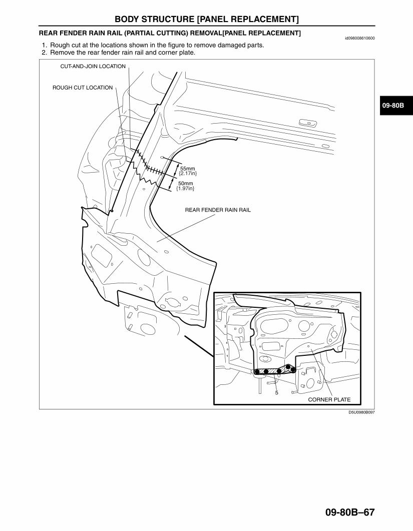
REAR FENDER RAIN RAIL (PARTIAL CUTTING) REMOVAL[PANEL REPLACEMENT]id098008610600
1. Rough cut at the locations shown in the figure to remove damaged parts.2. Remove the rear fender rain rail and corner plate.
End Of Sie
55mm
REAR FENDER RAIN RAIL
50mm{1.97in}
{2.17in}
ROUGH CUT LOCATION
CUT-AND-JOIN LOCATION
5CORNER PLATE
D5U0980B097
3426-1U-06F(09-80B).fm 67 ページ 2006年6月20日 火曜日 午後7時32分
BODY STRUCTURE [PANEL REPLACEMENT]
09-80B–68
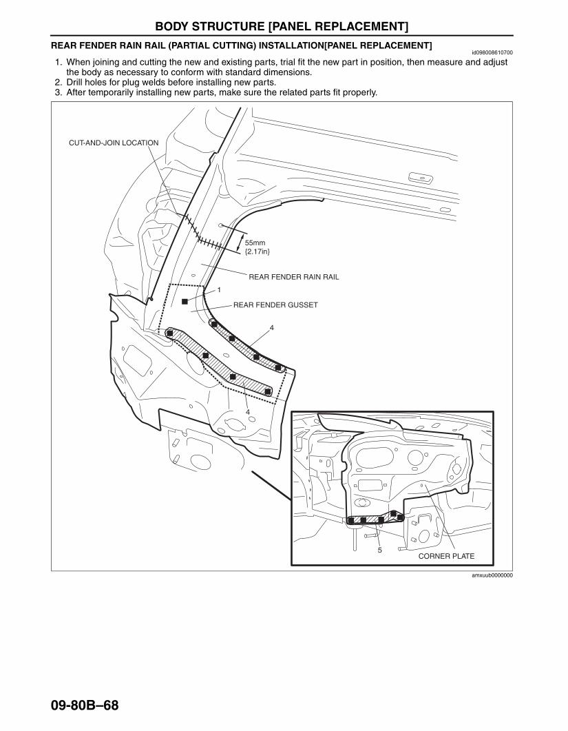
REAR FENDER RAIN RAIL (PARTIAL CUTTING) INSTALLATION[PANEL REPLACEMENT]id098008610700
1. When joining and cutting the new and existing parts, trial fit the new part in position, then measure and adjust the body as necessary to conform with standard dimensions.
2. Drill holes for plug welds before installing new parts.3. After temporarily installing new parts, make sure the related parts fit properly.
End Of Sie
55mm{2.17in}
5
4
4
1
REAR FENDER RAIN RAIL
REAR FENDER GUSSET
CUT-AND-JOIN LOCATION
CORNER PLATE
amxuub0000000
3426-1U-06F(09-80B).fm 68 ページ 2006年6月20日 火曜日 午後7時32分

BODY STRUCTURE [PANEL REPLACEMENT]
09-80B–69
09-80B
REAR DECK PANEL REMOVAL[PANEL REPLACEMENT]id098008610800
1. Remove the rear deck panel.
Convertible Top
2
2
8
2
719
19
REAR DECK PANEL
amxuub0000000
3426-1U-06F(09-80B).fm 69 ページ 2006年6月20日 火曜日 午後7時32分

BODY STRUCTURE [PANEL REPLACEMENT]
09-80B–70
Power Retractable Hardtop
End Of Sie
9
3
7
43
6
4
2
22
REAR DECK PANEL
amxuub00000010
3426-1U-06F(09-80B).fm 70 ページ 2006年6月20日 火曜日 午後7時32分

BODY STRUCTURE [PANEL REPLACEMENT]
09-80B–71
09-80B
REAR DECK PANEL INSTALLATION[PANEL REPLACEMENT]id098008610900
1. When installing new parts, measure and adjust the body as necessary to conform with standard dimensions.2. Drill holes for plug welds before installing new parts.3. After temporarily installing new parts, make sure the related parts fit properly.
Convertible Top
2
2
8
2
719
19
REAR DECK PANEL
amxuub0000001
3426-1U-06F(09-80B).fm 71 ページ 2006年6月20日 火曜日 午後7時32分
BODY STRUCTURE [PANEL REPLACEMENT]
09-80B–72
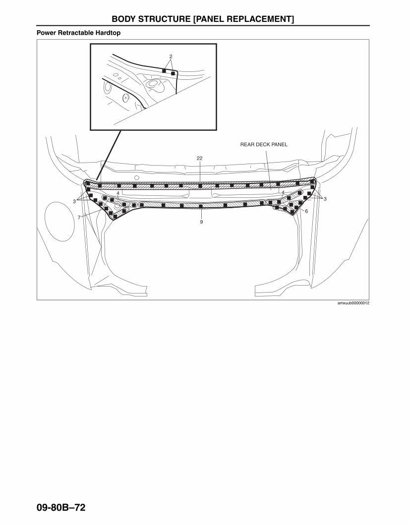
Power Retractable Hardtop
End Of Sie
9
3
7
43
6
4
2
22
REAR DECK PANEL
amxuub00000012
3426-1U-06F(09-80B).fm 72 ページ 2006年6月20日 火曜日 午後7時32分
BODY STRUCTURE [PANEL REPLACEMENT]
09-80B–73
09-80B
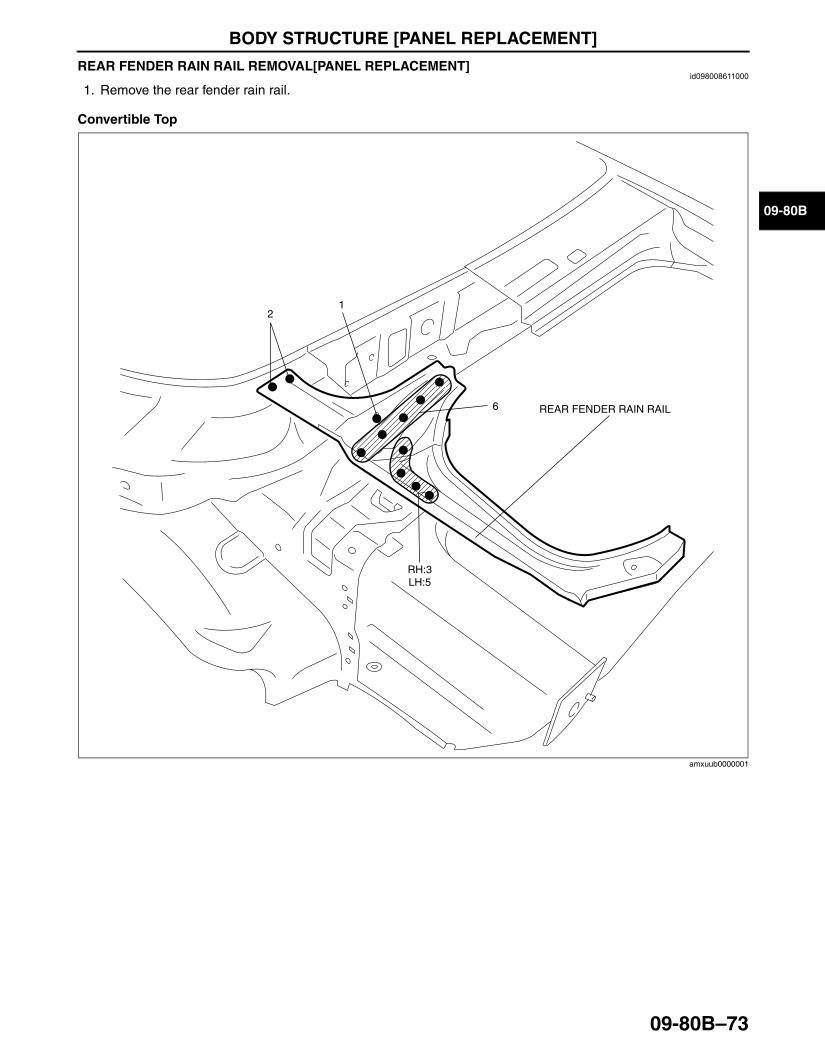
REAR FENDER RAIN RAIL REMOVAL[PANEL REPLACEMENT]id098008611000
1. Remove the rear fender rain rail.
Convertible Top
REAR FENDER RAIN RAIL6
12
RH:3LH:5
amxuub0000001
3426-1U-06F(09-80B).fm 73 ページ 2006年6月20日 火曜日 午後7時32分
BODY STRUCTURE [PANEL REPLACEMENT]
09-80B–74
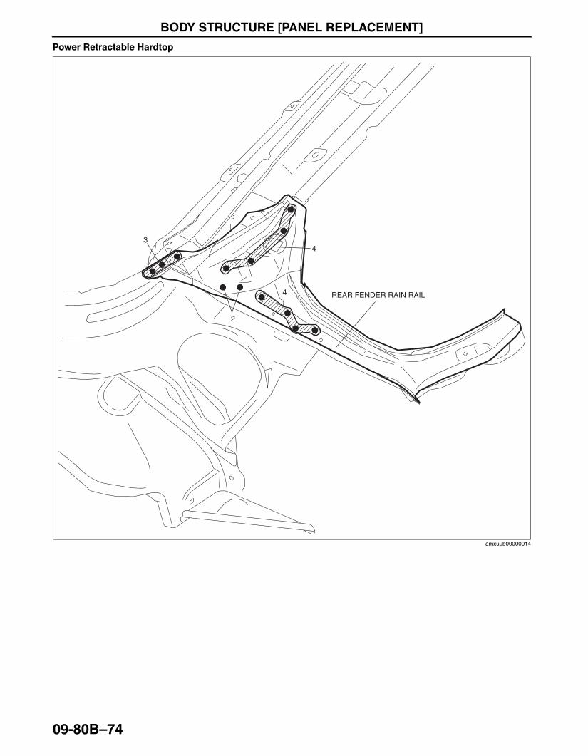
Power Retractable Hardtop
End Of Sie
2
34
4 REAR FENDER RAIN RAIL
amxuub00000014
3426-1U-06F(09-80B).fm 74 ページ 2006年6月20日 火曜日 午後7時32分
BODY STRUCTURE [PANEL REPLACEMENT]
09-80B–75
09-80B
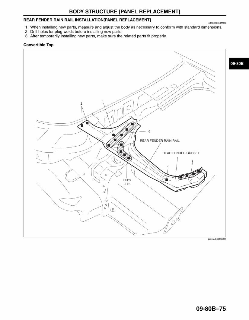
REAR FENDER RAIN RAIL INSTALLATION[PANEL REPLACEMENT]id098008611100
1. When installing new parts, measure and adjust the body as necessary to conform with standard dimensions.2. Drill holes for plug welds before installing new parts.3. After temporarily installing new parts, make sure the related parts fit properly.
Convertible Top
REAR FENDER RAIN RAIL
6
12
5
1
REAR FENDER GUSSET
RH:3LH:5
amxuub0000001
3426-1U-06F(09-80B).fm 75 ページ 2006年6月20日 火曜日 午後7時32分
BODY STRUCTURE [PANEL REPLACEMENT]
09-80B–76
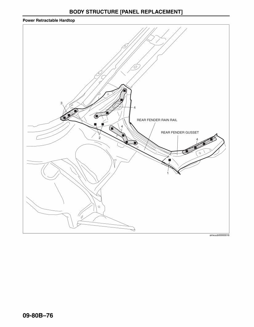
Power Retractable Hardtop
End Of Sie
2
34
4
REAR FENDER RAIN RAIL
4
1
REAR FENDER GUSSET
amxuub00000016
3426-1U-06F(09-80B).fm 76 ページ 2006年6月20日 火曜日 午後7時32分

BODY STRUCTURE [PANEL REPLACEMENT]
09-80B–77
09-80B
END PLATE REMOVAL[PANEL REPLACEMENT]id098008611200
1. Remove the bolt locations indicated by (A).2. Remove the end plate.
End Of Sie
(A)BOLT
6
12
14
2 2
END PLATE
1
D5U0980B103
3426-1U-06F(09-80B).fm 77 ページ 2006年6月20日 火曜日 午後7時32分
BODY STRUCTURE [PANEL REPLACEMENT]
09-80B–78
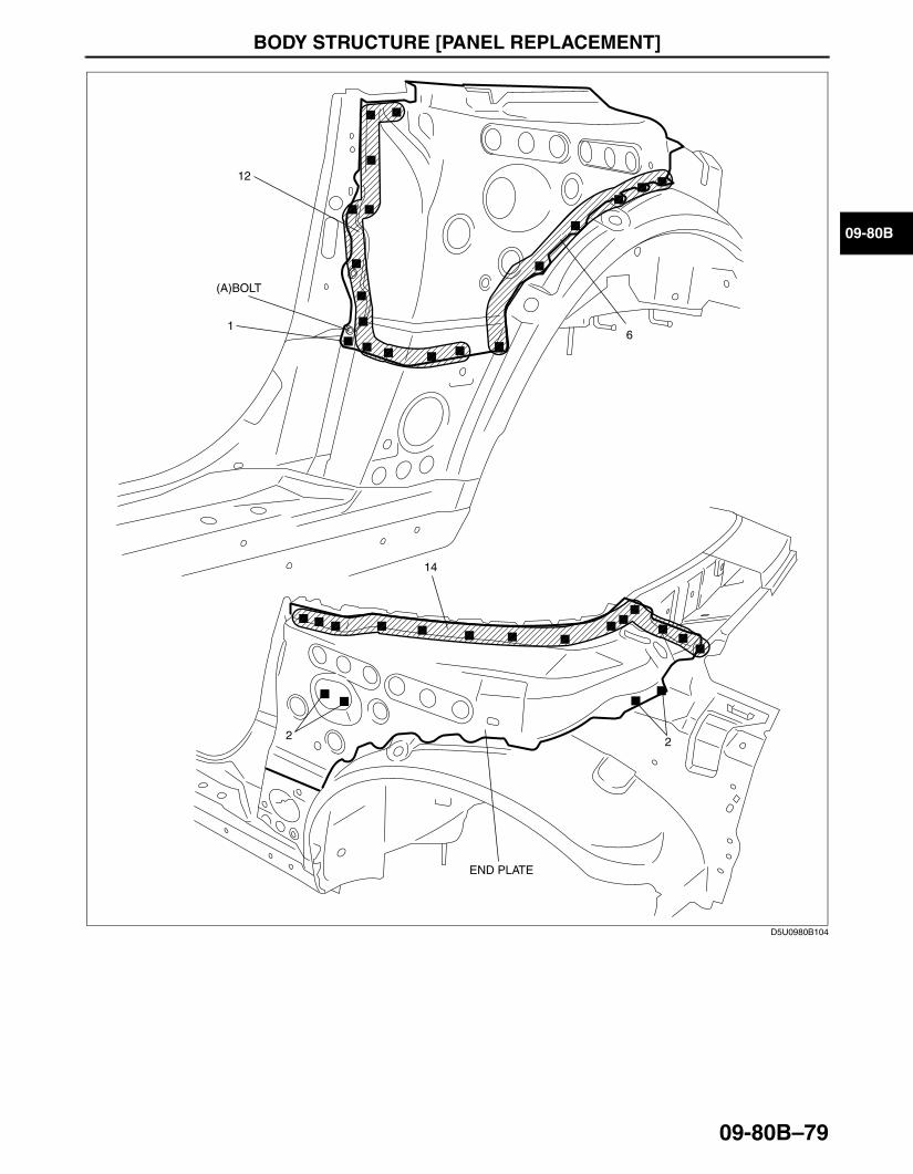
END PLATE INSTALLATION[PANEL REPLACEMENT]id098008611300
1. When installing new parts, measure and adjust the body as necessary to conform with standard dimensions.2. Drill holes for plug welds before installing new parts.3. After temporarily installing new parts, make sure the related parts fit properly.4. Install the bolt locations indicated by (A).
Tightening torque6.9—11.8 N·m {71—120 kgf·cm, 62—104 in·lbf}
5. Install the end plate.
3426-1U-06F(09-80B).fm 78 ページ 2006年6月20日 火曜日 午後7時32分
BODY STRUCTURE [PANEL REPLACEMENT]
09-80B–79
09-80B
End Of Sie
6
12
14
2 2
END PLATE
(A)BOLT
1
D5U0980B104
3426-1U-06F(09-80B).fm 79 ページ 2006年6月20日 火曜日 午後7時32分
BODY STRUCTURE [PANEL REPLACEMENT]
09-80B–80
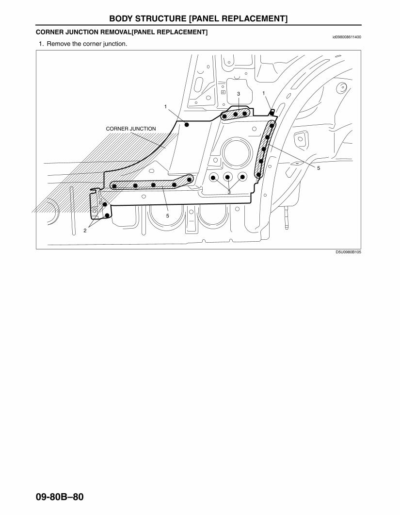
CORNER JUNCTION REMOVAL[PANEL REPLACEMENT]id098008611400
1. Remove the corner junction.
End Of Sie
5
5
2
1
1
3
3
CORNER JUNCTION
D5U0980B105
3426-1U-06F(09-80B).fm 80 ページ 2006年6月20日 火曜日 午後7時32分
BODY STRUCTURE [PANEL REPLACEMENT]
09-80B–81
09-80B
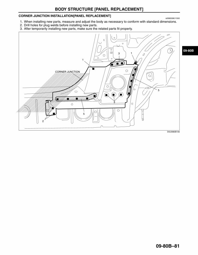
CORNER JUNCTION INSTALLATION[PANEL REPLACEMENT]id098008611500
1. When installing new parts, measure and adjust the body as necessary to conform with standard dimensions.2. Drill holes for plug welds before installing new parts.3. After temporarily installing new parts, make sure the related parts fit properly.
End Of Sie
5
5
2
1
1
3
3
CORNER JUNCTION
D5U0980B106
3426-1U-06F(09-80B).fm 81 ページ 2006年6月20日 火曜日 午後7時32分
BODY STRUCTURE [PANEL REPLACEMENT]
09-80B–82
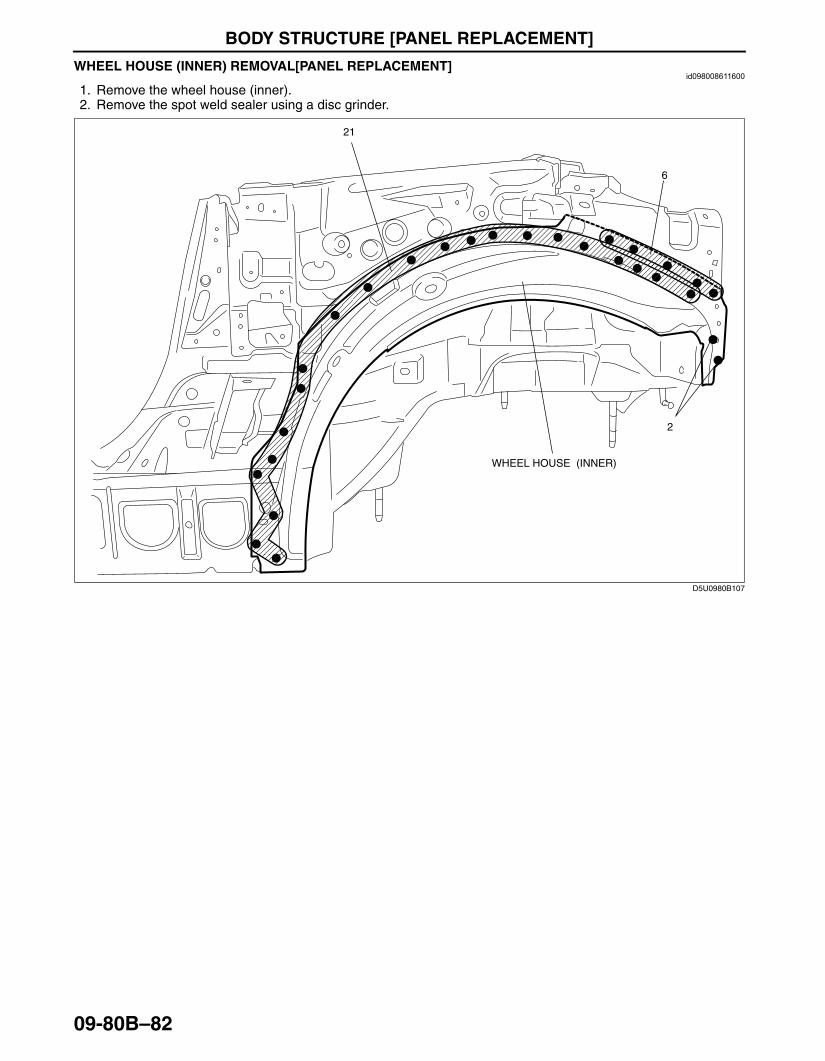
WHEEL HOUSE (INNER) REMOVAL[PANEL REPLACEMENT]id098008611600
1. Remove the wheel house (inner).2. Remove the spot weld sealer using a disc grinder.
End Of Sie
6
2
21
WHEEL HOUSE (INNER)
D5U0980B107
3426-1U-06F(09-80B).fm 82 ページ 2006年6月20日 火曜日 午後7時32分
BODY STRUCTURE [PANEL REPLACEMENT]
09-80B–83
09-80B
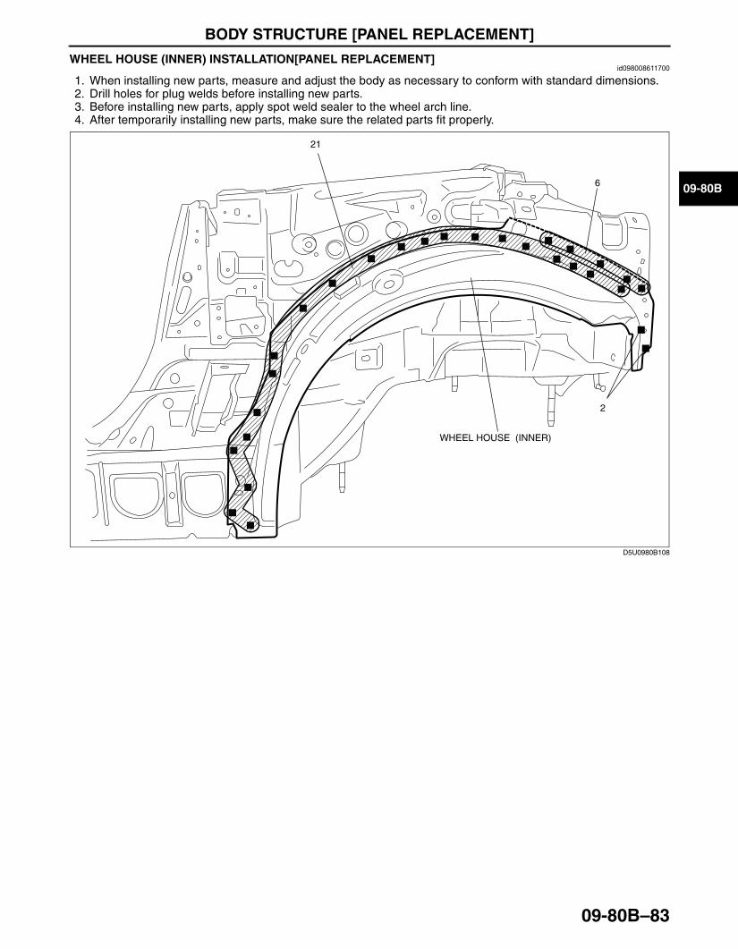
WHEEL HOUSE (INNER) INSTALLATION[PANEL REPLACEMENT]id098008611700
1. When installing new parts, measure and adjust the body as necessary to conform with standard dimensions.2. Drill holes for plug welds before installing new parts.3. Before installing new parts, apply spot weld sealer to the wheel arch line.4. After temporarily installing new parts, make sure the related parts fit properly.
End Of SieBM: TRUNK FLOOR PAN
6
2
21
WHEEL HOUSE (INNER)
D5U0980B108
3426-1U-06F(09-80B).fm 83 ページ 2006年6月20日 火曜日 午後7時32分
BODY STRUCTURE [PANEL REPLACEMENT]
09-80B–84
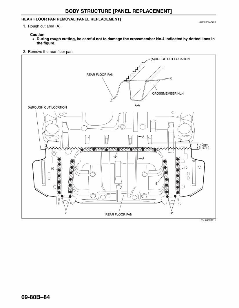
REAR FLOOR PAN REMOVAL[PANEL REPLACEMENT]id098008742700
1. Rough cut area (A).
Caution• During rough cutting, be careful not to damage the crossmember No.4 indicated by dotted lines in
the figure.
2. Remove the rear floor pan.
2
10
12
10
9
9
2
40mm
REAR FLOOR PAN
A-A
CROSSMEMBER No.4
A
A
{1.57in}
(A)ROUGH CUT LOCATION
REAR FLOOR PAN
(A)ROUGH CUT LOCATION
D5U0980B111
3426-1U-06F(09-80B).fm 84 ページ 2006年6月20日 火曜日 午後7時32分

BODY STRUCTURE [PANEL REPLACEMENT]
09-80B–85
09-80B
End Of Sie
41
5
D5U0980B112
3426-1U-06F(09-80B).fm 85 ページ 2006年6月20日 火曜日 午後7時32分
BODY STRUCTURE [PANEL REPLACEMENT]
09-80B–86
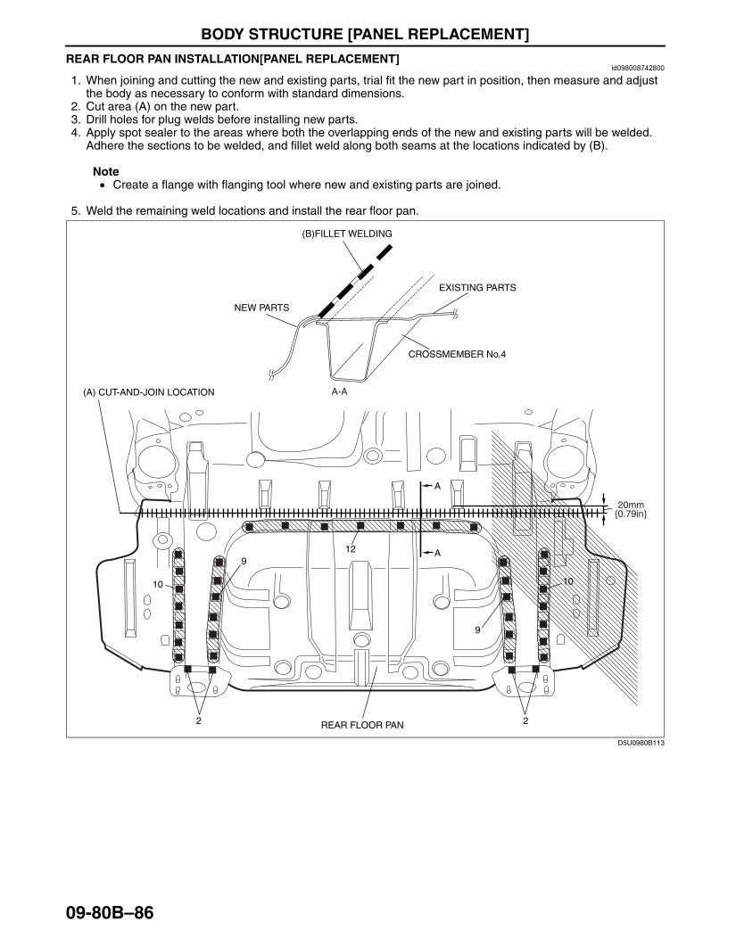
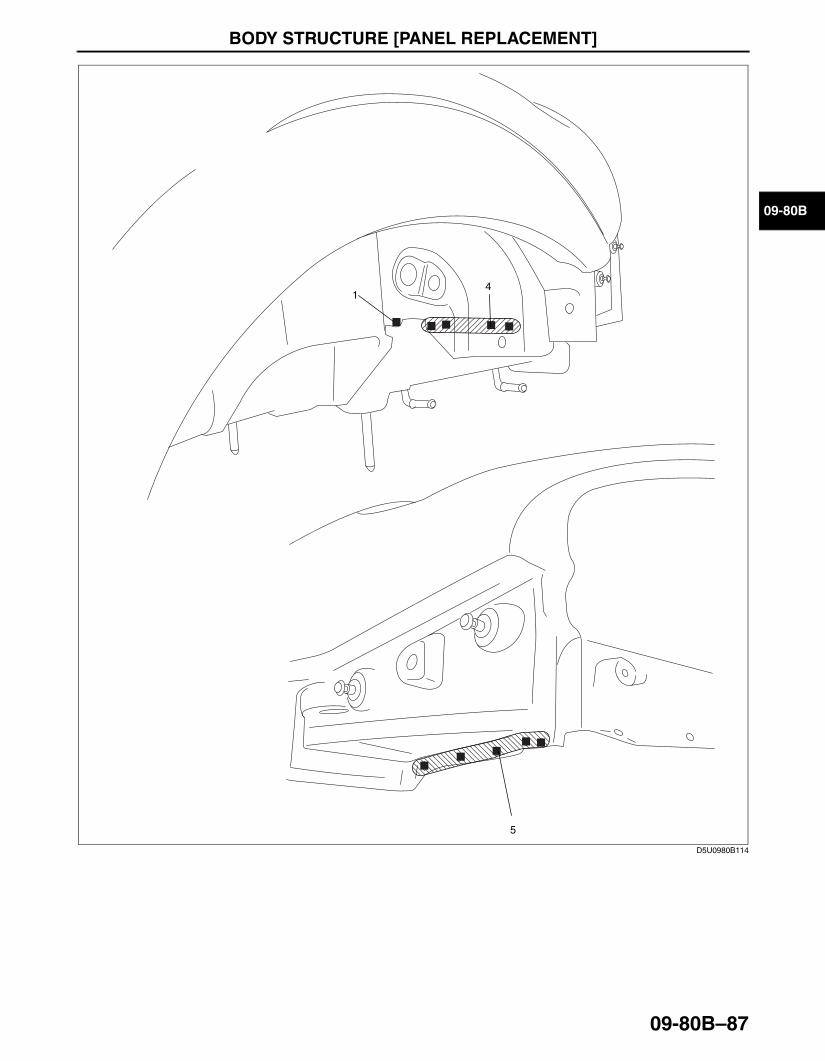
REAR FLOOR PAN INSTALLATION[PANEL REPLACEMENT]id098008742800
1. When joining and cutting the new and existing parts, trial fit the new part in position, then measure and adjust the body as necessary to conform with standard dimensions.
2. Cut area (A) on the new part.3. Drill holes for plug welds before installing new parts.4. Apply spot sealer to the areas where both the overlapping ends of the new and existing parts will be welded.
Adhere the sections to be welded, and fillet weld along both seams at the locations indicated by (B).
Note• Create a flange with flanging tool where new and existing parts are joined.
5. Weld the remaining weld locations and install the rear floor pan.
2
10
12
10
9
9
2
20mm
REAR FLOOR PAN
A-A
CROSSMEMBER No.4
A
A
{0.79in}
(A) CUT-AND-JOIN LOCATION
NEW PARTS
EXISTING PARTS
(B)FILLET WELDING
D5U0980B113
3426-1U-06F(09-80B).fm 86 ページ 2006年6月20日 火曜日 午後7時32分
BODY STRUCTURE [PANEL REPLACEMENT]
09-80B–87
09-80B
End Of SieBM: REAR SIDE FRAME
41
5
D5U0980B114
3426-1U-06F(09-80B).fm 87 ページ 2006年6月20日 火曜日 午後7時32分
BODY STRUCTURE [PANEL REPLACEMENT]
09-80B–88
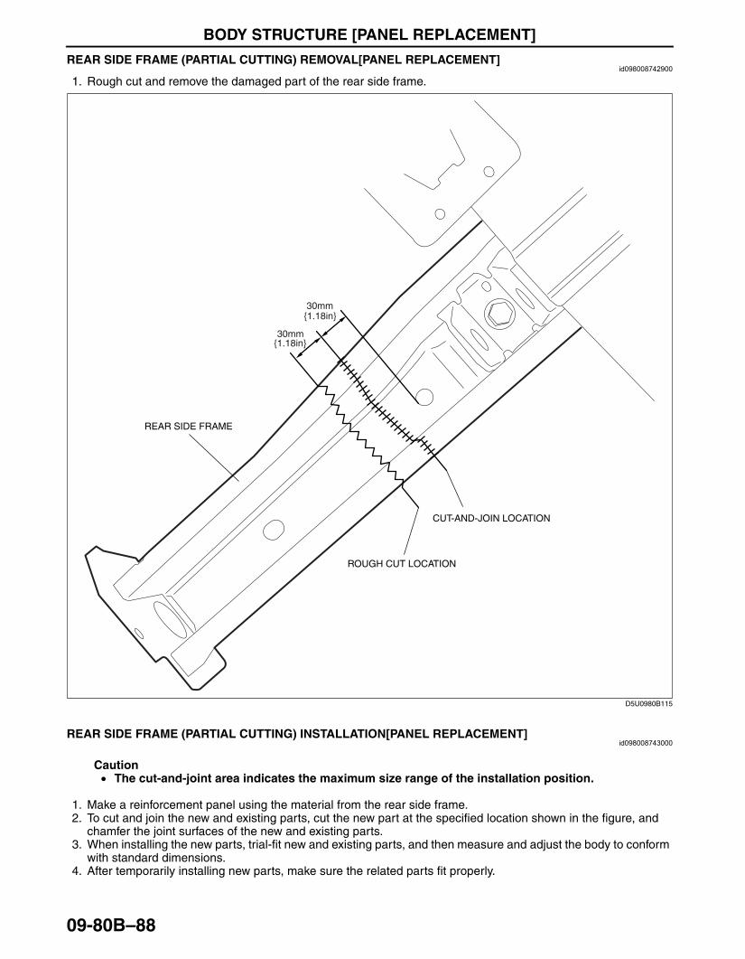
REAR SIDE FRAME (PARTIAL CUTTING) REMOVAL[PANEL REPLACEMENT]id098008742900
1. Rough cut and remove the damaged part of the rear side frame.
End Of SieREAR SIDE FRAME (PARTIAL CUTTING) INSTALLATION[PANEL REPLACEMENT]
id098008743000
Caution• The cut-and-joint area indicates the maximum size range of the installation position.
1. Make a reinforcement panel using the material from the rear side frame.2. To cut and join the new and existing parts, cut the new part at the specified location shown in the figure, and
chamfer the joint surfaces of the new and existing parts.3. When installing the new parts, trial-fit new and existing parts, and then measure and adjust the body to conform
with standard dimensions.4. After temporarily installing new parts, make sure the related parts fit properly.
30mm
30mm{1.18in}
ROUGH CUT LOCATION
CUT-AND-JOIN LOCATION
{1.18in}
REAR SIDE FRAME
D5U0980B115
3426-1U-06F(09-80B).fm 88 ページ 2006年6月20日 火曜日 午後7時32分
BODY STRUCTURE [PANEL REPLACEMENT]
09-80B–89
09-80B
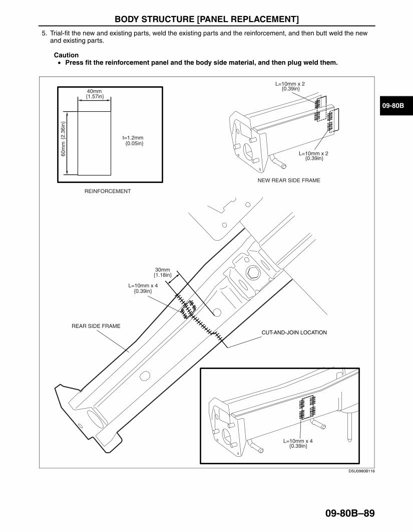
5. Trial-fit the new and existing parts, weld the existing parts and the reinforcement, and then butt weld the new and existing parts.
Caution• Press fit the reinforcement panel and the body side material, and then plug weld them.
End Of SieBM: ROOF PANEL
30mm
t=1.2mm{0.05in}
40mm{1.57in}
60m
m{2
.36i
n}
REINFORCEMENT
NEW REAR SIDE FRAME
L=10mm x 2{0.39in}
L=10mm x 2{0.39in}
L=10mm x 4{0.39in}
L=10mm x 4
{1.18in}
{0.39in}
REAR SIDE FRAMECUT-AND-JOIN LOCATION
D5U0980B116
3426-1U-06F(09-80B).fm 89 ページ 2006年6月20日 火曜日 午後7時32分
BODY STRUCTURE [PANEL REPLACEMENT]
09-80B–90
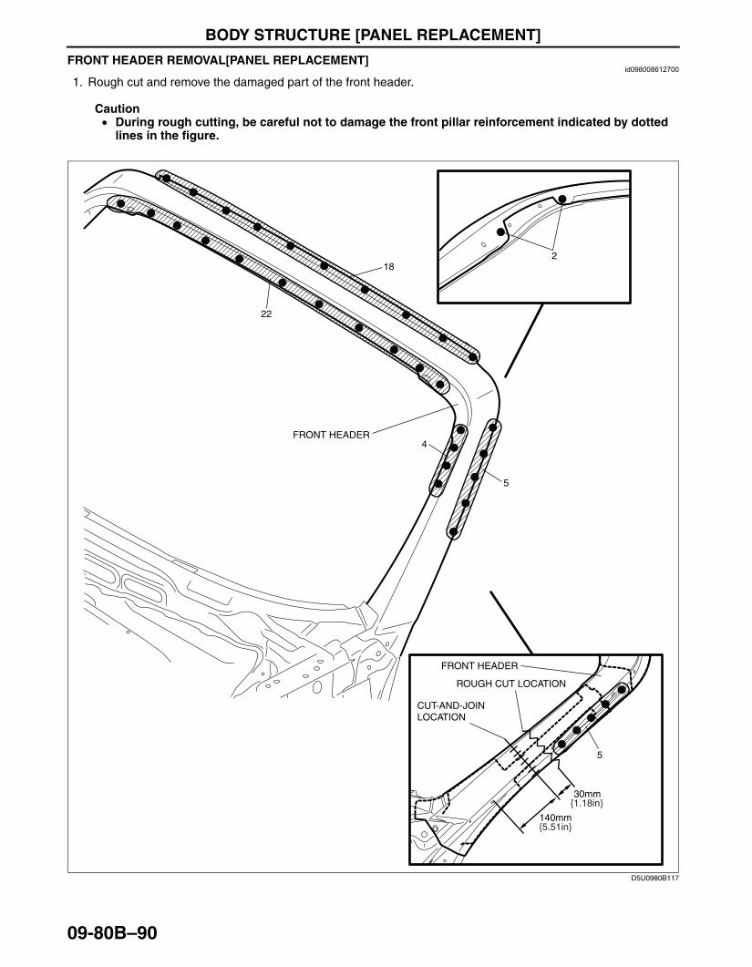
FRONT HEADER REMOVAL[PANEL REPLACEMENT]id098008612700
1. Rough cut and remove the damaged part of the front header.
Caution• During rough cutting, be careful not to damage the front pillar reinforcement indicated by dotted
lines in the figure.
End Of Sie
4
5
22
18
140mm
30mm
5
FRONT HEADER
2
ROUGH CUT LOCATION
CUT-AND-JOINLOCATION
{5.51in}
{1.18in}
FRONT HEADER
D5U0980B117
3426-1U-06F(09-80B).fm 90 ページ 2006年6月20日 火曜日 午後7時32分
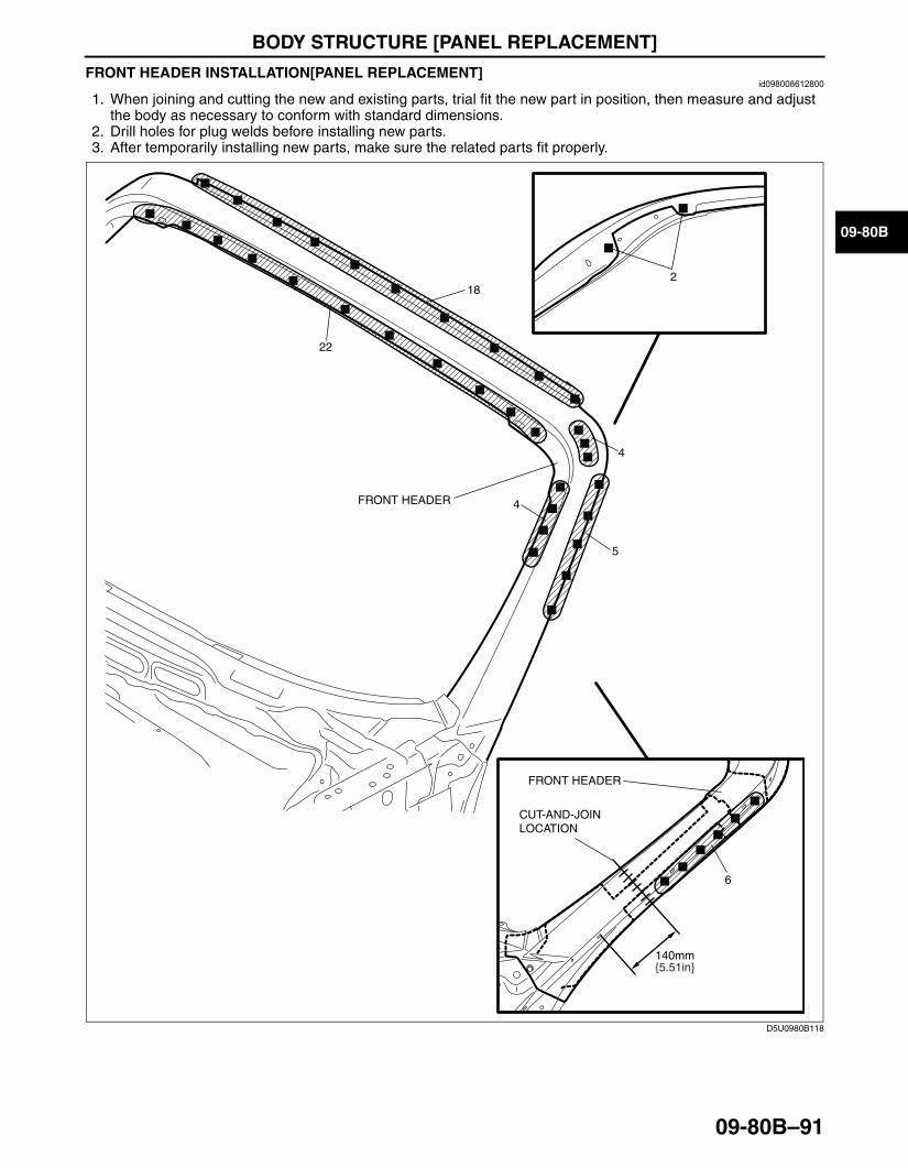
BODY STRUCTURE [PANEL REPLACEMENT]
09-80B–91
09-80B
FRONT HEADER INSTALLATION[PANEL REPLACEMENT]id098008612800
1. When joining and cutting the new and existing parts, trial fit the new part in position, then measure and adjust the body as necessary to conform with standard dimensions.
2. Drill holes for plug welds before installing new parts.3. After temporarily installing new parts, make sure the related parts fit properly.
End Of Sie
4
5
22
18
140mm
6
2
FRONT HEADER
CUT-AND-JOINLOCATION
{5.51in}
FRONT HEADER
4
D5U0980B118
3426-1U-06F(09-80B).fm 91 ページ 2006年6月20日 火曜日 午後7時32分

BODY STRUCTURE [WATER-PROOF AND RUST PREVENTIVE]
09-80C–1
09-80C
09-80C BODY STRUCTURE [WATER-PROOF AND RUST PREVENTIVE]BODY SEALING[WATER-PROOF AND
RUST PREVENTIVE] . . . . . . . . . . . . . . 09-80C–2UNDER COATING[WATER-PROOF AND
RUST PREVENTIVE] . . . . . . . . . . . . . . 09-80C–6
RUST PREVENTIVE TREATMENT[WATER-PROOF AND RUST PREVENTIVE] . . . . . . . . . . . . . . . . . . . . 09-80C–7
DUMPING SHEET REPLACEMENT[WATER-PROOF AND RUST PREVENTIVE] . . . . . . . . . . . . . . . . . . . . 09-80C–8
End of TocBM: WATER-PROOF AND RUST PREVENTIVE
3426-1U-06F(09-80C).fm 1 ページ 2006年6月20日 火曜日 午後3時40分

BODY STRUCTURE [WATER-PROOF AND RUST PREVENTIVE]
09-80C–2
BODY SEALING[WATER-PROOF AND RUST PREVENTIVE]id098009739800
Sealant is applied to the parts where the panels meet and to the hemmed parts of the door panel and hood panel to provide water proofing and rust proofing.
D5U0980B120
3426-1U-06F(09-80C).fm 2 ページ 2006年6月20日 火曜日 午後3時40分
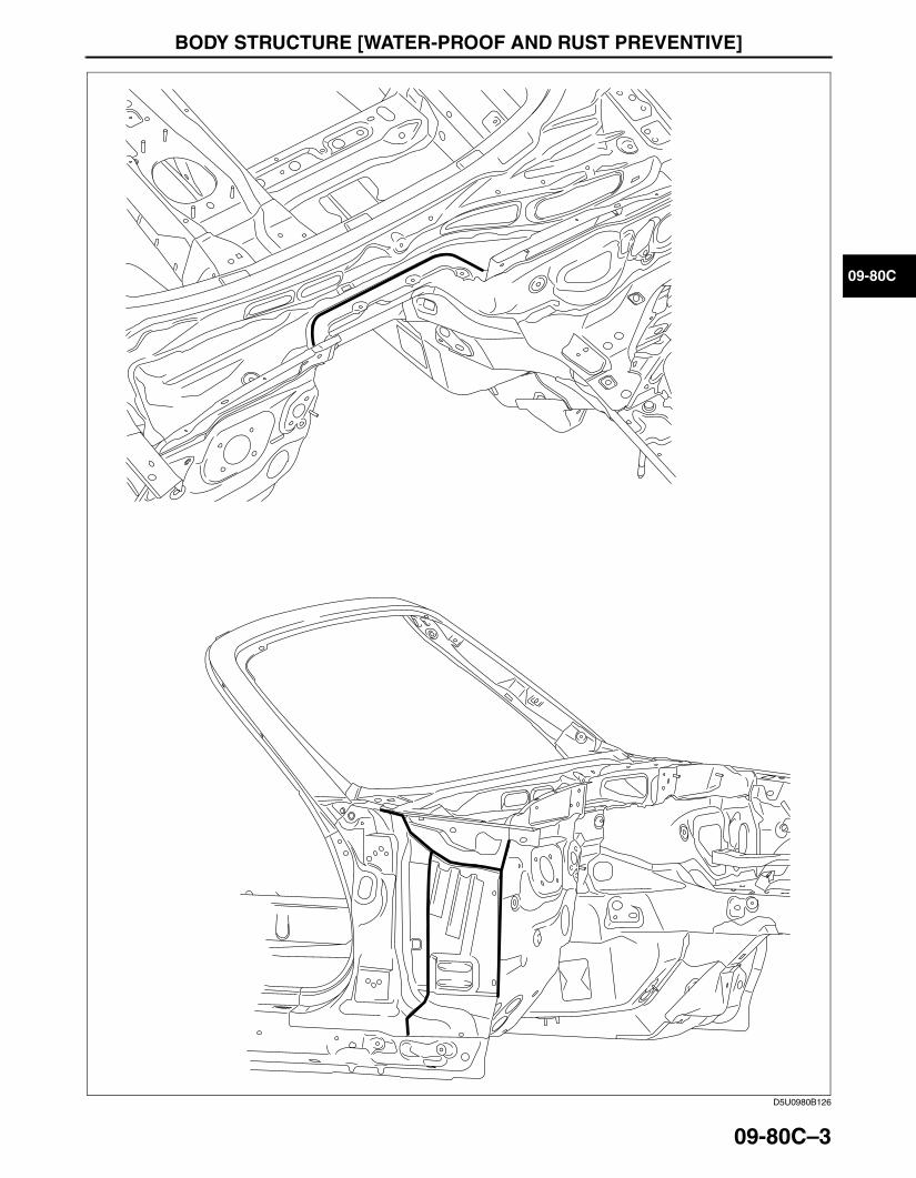
BODY STRUCTURE [WATER-PROOF AND RUST PREVENTIVE]
09-80C–3
09-80C
D5U0980B126
3426-1U-06F(09-80C).fm 3 ページ 2006年6月20日 火曜日 午後3時40分
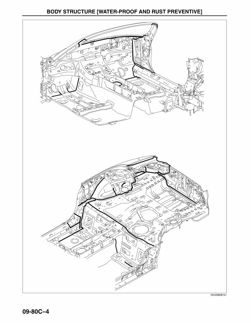
BODY STRUCTURE [WATER-PROOF AND RUST PREVENTIVE]
09-80C–4
D5U0980B121
3426-1U-06F(09-80C).fm 4 ページ 2006年6月20日 火曜日 午後3時40分

BODY STRUCTURE [WATER-PROOF AND RUST PREVENTIVE]
09-80C–5
09-80C
End Of Sie
D5U0980B122
3426-1U-06F(09-80C).fm 5 ページ 2006年6月20日 火曜日 午後3時40分
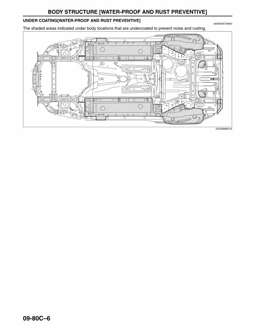
BODY STRUCTURE [WATER-PROOF AND RUST PREVENTIVE]
09-80C–6
UNDER COATING[WATER-PROOF AND RUST PREVENTIVE]id098009739900
The shaded areas indicated under body locations that are undercoated to prevent noise and rusting.End Of Sie
D5U0980B123
3426-1U-06F(09-80C).fm 6 ページ 2006年6月20日 火曜日 午後3時40分
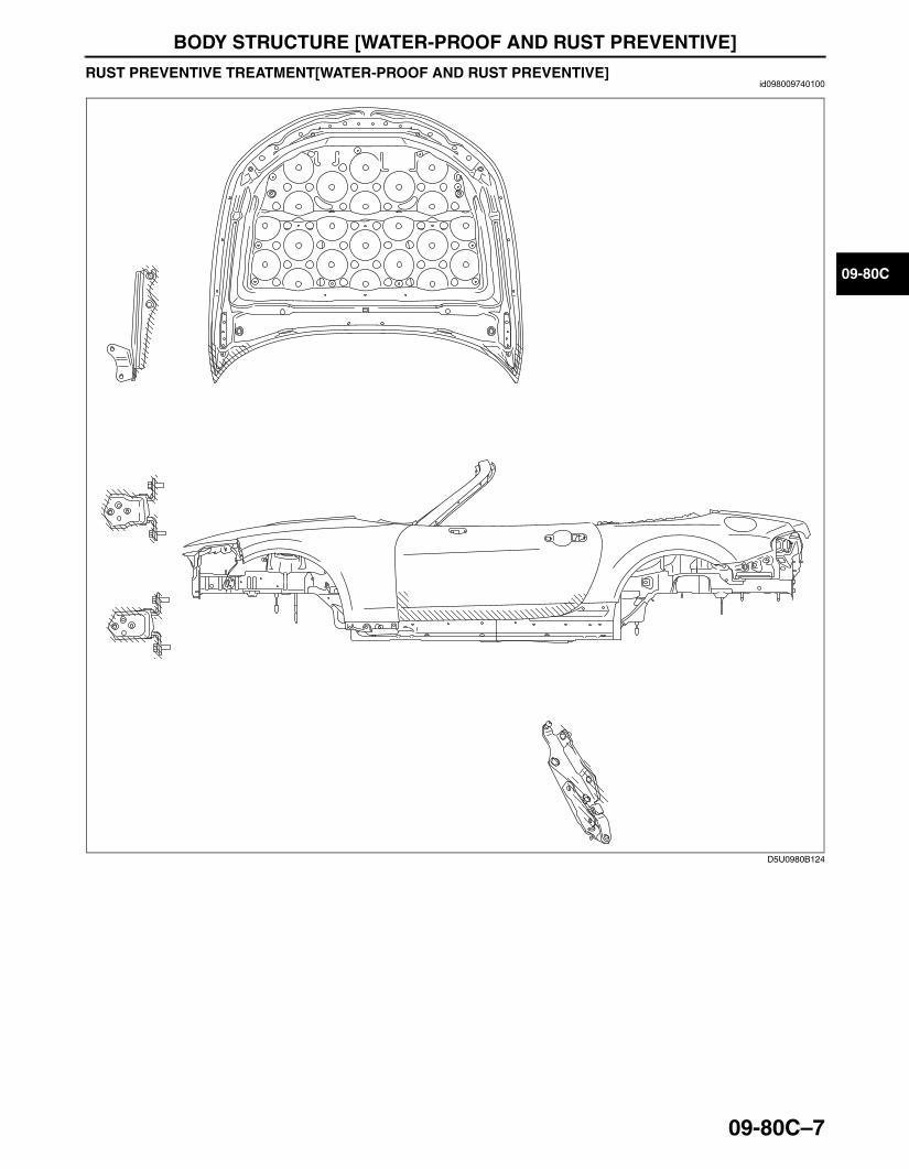
BODY STRUCTURE [WATER-PROOF AND RUST PREVENTIVE]
09-80C–7
09-80C
RUST PREVENTIVE TREATMENT[WATER-PROOF AND RUST PREVENTIVE]id098009740100
End Of Sie
D5U0980B124
3426-1U-06F(09-80C).fm 7 ページ 2006年6月20日 火曜日 午後3時40分

BODY STRUCTURE [WATER-PROOF AND RUST PREVENTIVE]
09-80C–8
DUMPING SHEET REPLACEMENT[WATER-PROOF AND RUST PREVENTIVE]id098009745700
End Of Sie
D5U0980B125
3426-1U-06F(09-80C).fm 8 ページ 2006年6月20日 火曜日 午後3時40分
BODY STRUCTURE [DIMENSIONS]
09-80D–1
09-80D
09-80D BODY STRUCTURE [DIMENSIONS]UNDERBODY FLAT-PLANE
DIMENSIONS[DIMENSIONS] . . . . . . . . 09-80D–2UNDERBODY FRONT STRAIGHT-LINE
DIMENSIONS[DIMENSIONS] . . . . . . . . 09-80D–3UNDERBODY REAR STRAIGHT-LINE
DIMENSIONS[DIMENSIONS] . . . . . . . . 09-80D–4FRONT BODY STRAIGHT-LINE
DIMENSIONS (1)[DIMENSIONS] . . . . . 09-80D–6FRONT BODY STRAIGHT-LINE
DIMENSIONS (2)[DIMENSIONS] . . . . . 09-80D–7FRONT BODY STRAIGHT-LINE
DIMENSIONS (3)[DIMENSIONS] . . . . . 09-80D–8
CABIN SIDE FRAME STRAIGHT-LINE DIMENSIONS[DIMENSIONS] . . . . . . . . . . . . . . . . . . . . 09-80D–9
ROOM STRAIGHT-LINE DIMENSIONS (1)[DIMENSIONS]. . . . . . . . . . . . . . . . . . 09-80D–10
ROOM STRAIGHT-LINE DIMENSIONS (2)[DIMENSIONS]. . . . . . . . . . . . . . . . . . 09-80D–11
ROOM STRAIGHT-LINE DIMENSIONS (3)[DIMENSIONS]. . . . . . . . . . . . . . . . . . 09-80D–12
REAR BODY STRAIGHT-LINE DIMENSIONS [DIMENSIONS] . . . . . . . . 09-80D–13
End of TocBM: UNDERBODY
3426-1U-06F(09-80D).fm 1 ページ 2006年6月20日 火曜日 午後3時41分

BODY STRUCTURE [DIMENSIONS]
09-80D–2
UNDERBODY FLAT-PLANE DIMENSIONS[DIMENSIONS]id098010740400
• The following figures are bottom and side views.
.
A B C D E F G H I K L M N OJ
mm
796
778
793
964
793
315
263
146
115
282
324 395 525 175 305 265 235 285
304
197
104 40 40
175 86 65 276
458
193
317
549
RH
:142
LH:1
97
810
796
796
400
396
1,24
0
992
828
1,02
1
824
834
RH
LH
{31.
34}
{30.
63}
{31.
22}
{37.
95}
{31.
22}
{12.
40}
{10.35}
{5.75}
{4.53}
{11.10}
{12.76} {15.55} {20.67} {6.89} {12.01} {10.43} {9.25} {11.22}
{11.
97}
{7.7
6}
{4.0
9}
{1.5
7}
{1.5
7}
{6.8
9}
{3.3
9}
{2.5
6}
{10.
87}
{18.
03}
{7.6
0}
{12.
48}
{21.
61}
{5.5
9}{7
.76}
{31.
89}
{31.
34}
{31.
34}
{15.
75}
{15.
60}
{48.
82}
{39.
06}
{32.
60}
{40.
20}
{32.
44}
{32.
83}
{in}
D5U0980B001
Point symbol Designation
Hole diameter or bolt or nut size mm {in}
A Front side frame datum hole ø7 {0.28}
B Crossmember No.1 datum hole ø7 {0.28}
C Engine mounting bolt M14 {0.55}
D Front suspension mounting block ø64 {2.52}
E Engine mounting bolt M14 {0.55}F Front frame rear datum hole ø16 {0.63}
G Front frame rear datum slotø16 x 20
{0.63 x 0.79}
H Front B frame datum hole ø12 {0.47}
I Front B frame datum slotø12 x 18
{0.47 x 0.71}J Rear side frame datum hole ø16 {0.63}
K Rear crossmember mounting bolt M14 {0.55}
L Rear crossmember mounting bolt M14 {0.55}
M Rear suspension mounting block ø97 {3.82}
Point symbol Designation
Hole diameter or bolt or nut size mm {in}
3426-1U-06F(09-80D).fm 2 ページ 2006年6月20日 火曜日 午後3時41分

BODY STRUCTURE [DIMENSIONS]
09-80D–3
09-80D
End Of SieBM: UNDERBODYUNDERBODY FRONT STRAIGHT-LINE DIMENSIONS[DIMENSIONS]
id098010748000
• The following figure is a bottom view.
.
N Rear crossmember mounting bolt M14 {0.55}
Point symbol Designation
Hole diameter or bolt or nut size mm {in}
O Rear side frame datum slotø16 x 20
{0.63 x 0.79}
Point symbol Designation
Hole diameter or bolt or nut size mm {in}
LHR
H
B E FA C G H
263
830
285
803
802
127
330
868
855
851
395
889
181
806
115
833
1,550
1,742
1,157
297
mm
{7.13}
{5.00}
{12.99} {15.55}{11.22}{10.35}
{32.68} {31.73}
{33.66}
{34.17}
{68.58}
{45.55}
{35.00}
{33.50}
{32.80}
{31.61}
{31.57}
{4.53}
{11.69}
{61.02}{in}
D5U0980B020
A DA B,C E,F G H
E
B
F
C
FrFr Fr
Fr
Fr
D5U0980B021
Point symbol Designation
Hole diameter or bolt or nut size mm {in}
A Front side frame datum hole ø7 {0.28} B Crossmember No.1 datum hole ø7 {0.28}
Point symbol Designation
Hole diameter or bolt or nut size mm {in}
3426-1U-06F(09-80D).fm 3 ページ 2006年6月20日 火曜日 午後3時41分

BODY STRUCTURE [DIMENSIONS]
09-80D–4
End Of SieUNDERBODY REAR STRAIGHT-LINE DIMENSIONS[DIMENSIONS]
id098010748100
• The following figure is a bottom view.
C Engine mounting bolt M14 {0.55}E Engine mounting bolt M14 {0.55}F Front frame rear datum hole ø16 {0.63}
Point symbol Designation
Hole diameter or bolt or nut size mm {in}
G Front frame rear datum slotø16 x 20
{0.63 x 0.79}H Front B frame datum hole ø12 {0.47}
Point symbol Designation
Hole diameter or bolt or nut size mm {in}
K N OH I J L
965
962
542
295
1,035
1,039
298
1,133
522
330
349
971
1,522
863
9811,157
249 311
885
mm
{21.34}
{12.99}
{11.61}
{11.73}
{13.74}{9.80} {12.24}
{40.91}
{40.75}
{45.55}
{38.23}
{59.92}
{20.55}
{44.61}
{33.98}
{38.62}
{34.84}{37.99}
{37.87}
{in}
D5U0980B022
3426-1U-06F(09-80D).fm 4 ページ 2006年6月20日 火曜日 午後3時41分
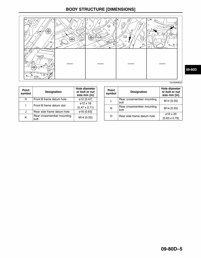
BODY STRUCTURE [DIMENSIONS]
09-80D–5
09-80D
.
End Of SieBM: FRONT BODY
I H J K
K
L N
O
L,N
Fr
FrFr Fr Fr Fr
D5U0980B023
Point symbol Designation
Hole diameter or bolt or nut size mm {in}
H Front B frame datum hole ø12 {0.47}
I Front B frame datum slotø12 x 18
{0.47 x 0.71}J Rear side frame datum hole ø16 {0.63}
K Rear crossmember mounting bolt M14 {0.55}
L Rear crossmember mounting bolt M14 {0.55}
N Rear crossmember mounting bolt M14 {0.55}
O Rear side frame datum holeø16 x 20
{0.63 x 0.79}
Point symbol Designation
Hole diameter or bolt or nut size mm {in}
3426-1U-06F(09-80D).fm 5 ページ 2006年6月20日 火曜日 午後3時41分

BODY STRUCTURE [DIMENSIONS]
09-80D–6
FRONT BODY STRAIGHT-LINE DIMENSIONS (1)[DIMENSIONS]id098010740600
.
A
B
C
D
E
F
G
A'
B'
C'
F'
E'
mm
1,330
1,478
1,5201,286
1,006125
984
560
6071088
543943
868
437
511
D'
{38.74}
{52.36}
{58.19}
{in}
{22.05}
{23.90}
{42.83}
{21.38}
{34.17}{37.13}
{39.61}
{50.63}
{59.84}
{17.20}{4.92}
{20.12}
D5U0980B004
A B
G'
C
G
D E
F G,G'
Fr FrFrFr
FrFr
Fr
D5U0980B005
Point symbol Designation
Hole diameter or bolt or nut size mm {in}
A Front header notch -
B Front header projection location -
C Front fender installation slotø10 x 12
{0.39 x 0.47}
D Front combination light installation hole ø7 {0.28}
E Front combination light installation hole ø7 {0.28}
F Front bumper reinforcement installation hole ø14 {0.55}
G Hood bracket datum hole ø10 {0.39}
G’ Hood bracket datum slotø10 x 14
{0.39 x 0.55}
Point symbol Designation
Hole diameter or bolt or nut size mm {in}
3426-1U-06F(09-80D).fm 6 ページ 2006年6月20日 火曜日 午後3時41分
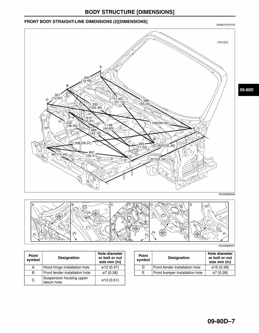
BODY STRUCTURE [DIMENSIONS]
09-80D–7
09-80D
End Of Sie
FRONT BODY STRAIGHT-LINE DIMENSIONS (2)[DIMENSIONS]id098010740700
.
End Of Sie
1,3981,451
1,548
1,327
1,508
1,330
1,138
1,086
1,232
495
822285
327
912
897367
mm
{55.04}{57.13}
{60.94}
{52.24}
{59.37}
{52.36}
{44.80}
{42.76}
{48.50}
{19.49}
{32.36}{11.22}
{12.87}
{35.91}
{35.31}{14.45}
A
B
C
D
E
A'
B'
E'
{in}
C'
D'
D5U0980B006
A B C D E
Fr Fr FrFr Fr
D5U0980B007
Point symbol Designation
Hole diameter or bolt or nut size mm {in}
A Hood hinge installation hole ø12 {0.47}B Front fender installation hole ø7 {0.28}
C Suspension housing upper datum hole ø13 {0.51}
D Front fender installation hole ø10 {0.39}E Front bumper installation hole ø7 {0.28}
Point symbol Designation
Hole diameter or bolt or nut size mm {in}
3426-1U-06F(09-80D).fm 7 ページ 2006年6月20日 火曜日 午後3時41分

BODY STRUCTURE [DIMENSIONS]
09-80D–8
FRONT BODY STRAIGHT-LINE DIMENSIONS (3)[DIMENSIONS]id098010740800
.
1,042
1,232
1,013
965
992
897
805
446
387
957
mm
{41.02}
{48.50}
{39.88}
{37.99}
{39.06}
{35.31}
{31.69}
{17.56}
{15.24}
{37.68}
A
B
C
D
E
F
G
A'
C'
D'
F'
G'
{in}
D5U0980B008
B C D E
F G
FrFr
Fr
Fr Fr
Fr
A
Fr
D5U0980B009
3426-1U-06F(09-80D).fm 8 ページ 2006年6月20日 火曜日 午後3時41分

BODY STRUCTURE [DIMENSIONS]
09-80D–9
09-80D
End Of SieBM: CABIN SIDE FRAMECABIN SIDE FRAME STRAIGHT-LINE DIMENSIONS[DIMENSIONS]
id098010743600
.
End Of SieBM: ROOM
Point symbol Designation
Hole diameter or bolt or nut size mm {in}
A Front header notch -B Wiper installation hole ø7 {0.28}C Hood hinge installation hole ø12 {0.47}D Front fender installation hole ø7 {0.28}
E Suspension mounting reinforcement datum hole ø8.2 {0.32}
F Front fender installation hole ø10 {0.39}
G Front side frame outer datum slot
ø10 x 14{0.39 x 0.55}
Point symbol Designation
Hole diameter or bolt or nut size mm {in}
1,135
1,130
1,133
1,250
715
900
828
754
948
mm
{44.69}
{44.49}{44.61} {49.21}
{28.15}
{35.43}
{32.60}
{29.69}
{37.32}
A
B
C
D
E
F
G
{in}
D5U0980B010
Fr
Fr Fr Fr Fr Fr
A
G
B
F
C D E
D5U0980B011
Point symbol Designation
Hole diameter or bolt or nut size mm {in}
A Front side frame datum hole ø20 {0.79}B Door hinge installation hole ø12 {0.47}C Door hinge installation hole ø12 {0.47}D Front header notch -
E Rear pillar notch -F Door switch installation hole ø7.2 {0.28}
G Rear fender panel standard square hole
8 x 10{0.31 x 0.39}
Point symbol Designation
Hole diameter or bolt or nut size mm {in}
3426-1U-06F(09-80D).fm 9 ページ 2006年6月20日 火曜日 午後3時41分
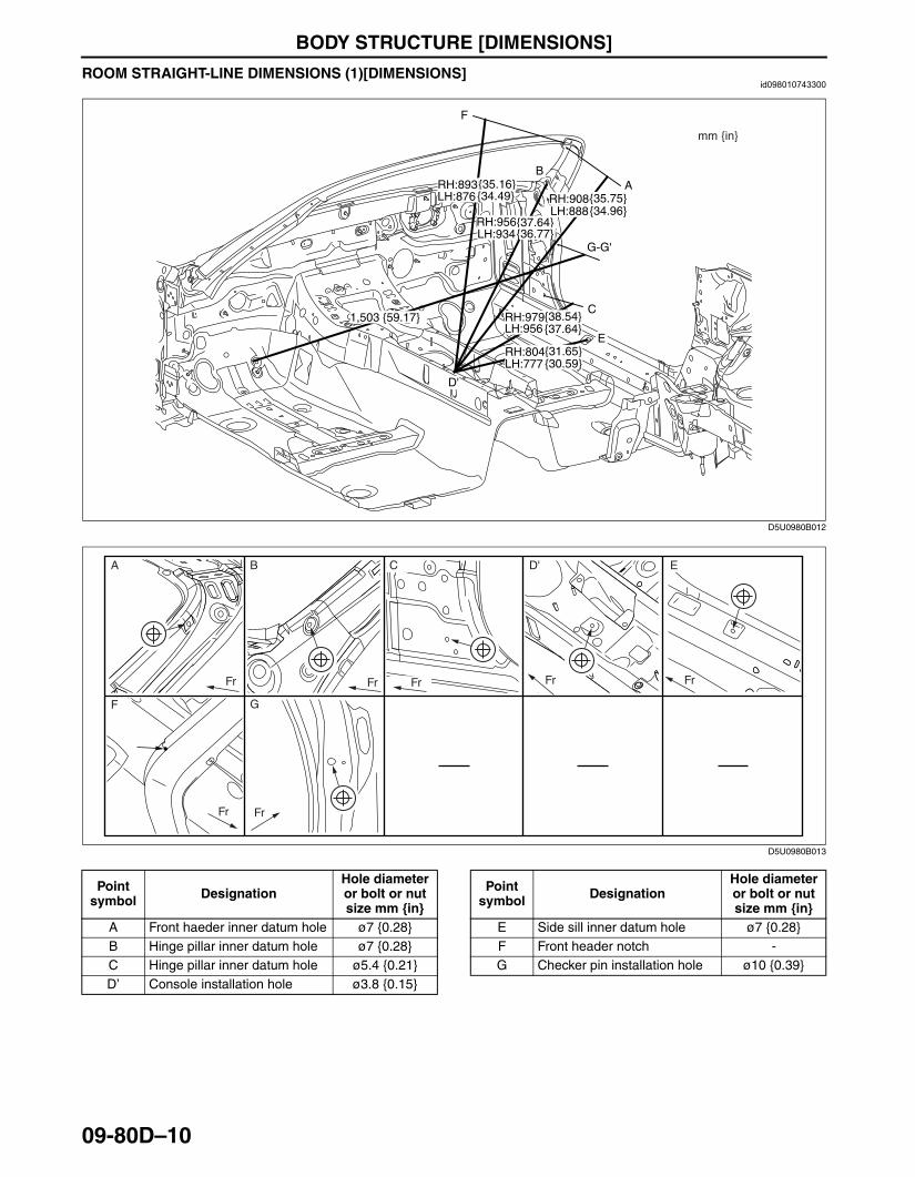
BODY STRUCTURE [DIMENSIONS]
09-80D–10
ROOM STRAIGHT-LINE DIMENSIONS (1)[DIMENSIONS]id098010743300
.
End Of Sie
1,503
RH:908LH:888
RH:956LH:934
RH:979LH:956
RH:804LH:777
RH:893LH:876
mm
{59.17}
{35.75}{34.96}
{37.64}{36.77}
{38.54}{37.64}
{31.65}{30.59}
{35.16}{34.49}
A
F
B
C
G-G'
E
D'
{in}
D5U0980B012
Fr
FrFr
Fr Fr Fr Fr
A B
GF
C D' E
D5U0980B013
Point symbol Designation
Hole diameter or bolt or nut size mm {in}
A Front haeder inner datum hole ø7 {0.28}B Hinge pillar inner datum hole ø7 {0.28}C Hinge pillar inner datum hole ø5.4 {0.21}D’ Console installation hole ø3.8 {0.15}
E Side sill inner datum hole ø7 {0.28}F Front header notch -G Checker pin installation hole ø10 {0.39}
Point symbol Designation
Hole diameter or bolt or nut size mm {in}
3426-1U-06F(09-80D).fm 10 ページ 2006年6月20日 火曜日 午後3時41分
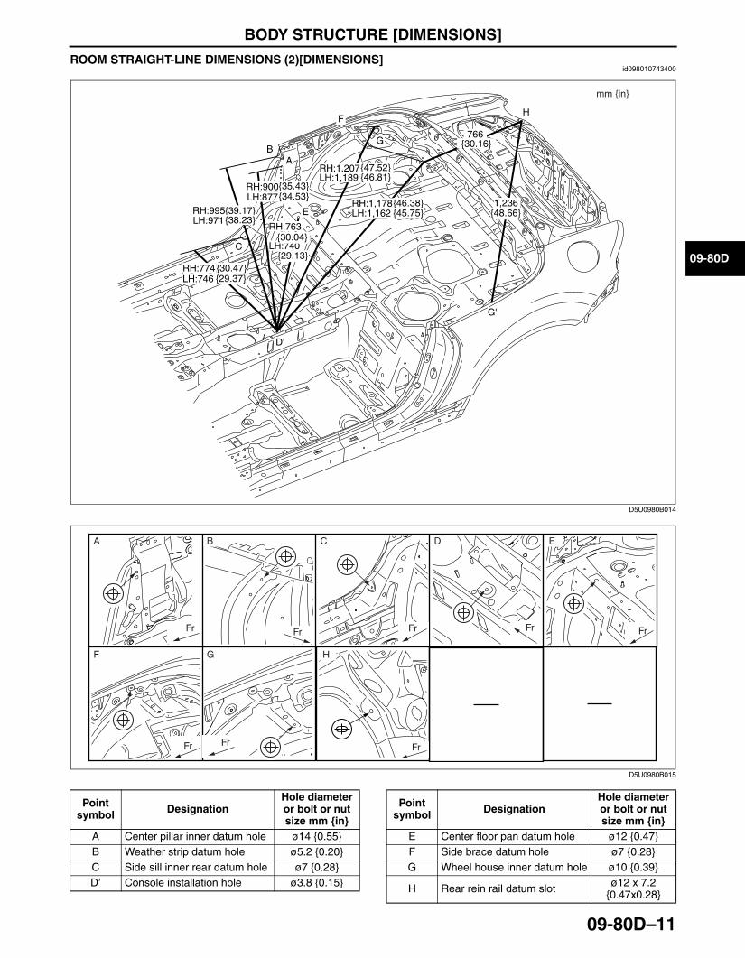
BODY STRUCTURE [DIMENSIONS]
09-80D–11
09-80D
ROOM STRAIGHT-LINE DIMENSIONS (2)[DIMENSIONS]id098010743400
.
RH:1,207LH:1,189
RH:1,178LH:1,162
1,236
RH:900LH:877
RH:995LH:971
RH:774LH:746
RH:763
LH:740
766
mm
{47.52}{46.81}
{46.38}{45.75} {48.66}
{35.43}{34.53}
{39.17}{38.23}
{30.47}{29.37}
{30.04}
{29.13}
{30.16}
A
H
B
C
G
F
E
G'
D'
{in}
D5U0980B014
Fr Fr Fr
Fr Fr
Fr
Fr
Fr
A B
F G H
C D' E
D5U0980B015
Point symbol Designation
Hole diameter or bolt or nut size mm {in}
A Center pillar inner datum hole ø14 {0.55}B Weather strip datum hole ø5.2 {0.20}C Side sill inner rear datum hole ø7 {0.28}D’ Console installation hole ø3.8 {0.15}
E Center floor pan datum hole ø12 {0.47}F Side brace datum hole ø7 {0.28}G Wheel house inner datum hole ø10 {0.39}
H Rear rein rail datum slot ø12 x 7.2 {0.47x0.28}
Point symbol Designation
Hole diameter or bolt or nut size mm {in}
3426-1U-06F(09-80D).fm 11 ページ 2006年6月20日 火曜日 午後3時41分
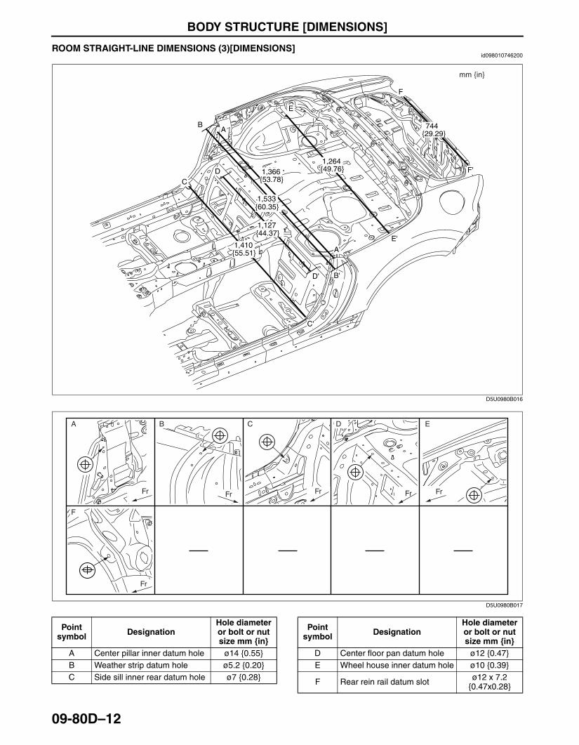
BODY STRUCTURE [DIMENSIONS]
09-80D–12
End Of Sie
ROOM STRAIGHT-LINE DIMENSIONS (3)[DIMENSIONS]id098010746200
.
End Of SieBM: REAR BODY
1,366
1,533
1,410
1,127
1,264
744
mm
{53.78}
{60.35}
{55.51}
{44.37}
{49.76}
{29.29}AB
CD
E
F
A'
D' B'
C'
E'
F'
{in}
D5U0980B016
Fr Fr Fr Fr
Fr
Fr
A B
F
C D E
D5U0980B017
Point symbol Designation
Hole diameter or bolt or nut size mm {in}
A Center pillar inner datum hole ø14 {0.55}B Weather strip datum hole ø5.2 {0.20}C Side sill inner rear datum hole ø7 {0.28}
D Center floor pan datum hole ø12 {0.47}E Wheel house inner datum hole ø10 {0.39}
F Rear rein rail datum slot ø12 x 7.2 {0.47x0.28}
Point symbol Designation
Hole diameter or bolt or nut size mm {in}
3426-1U-06F(09-80D).fm 12 ページ 2006年6月20日 火曜日 午後3時41分
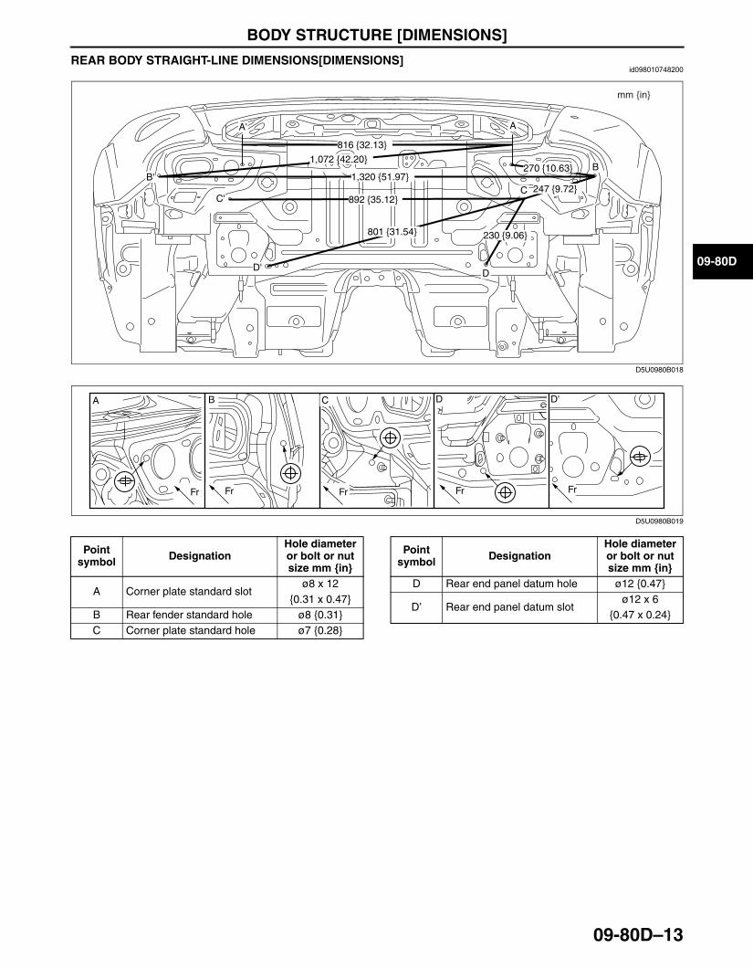
BODY STRUCTURE [DIMENSIONS]
09-80D–13
09-80D
REAR BODY STRAIGHT-LINE DIMENSIONS[DIMENSIONS]id098010748200
.
End Of Sie
1,072
1,320
816
270
247
230
892
801
mm
{42.20}
{51.97}
{32.13}
{10.63}
{9.72}
{9.06}
{35.12}
{31.54}
A
B
C
D
A'
B'
C'
D'
{in}
D5U0980B018
A B C D D'
Fr Fr Fr FrFr
D5U0980B019
Point symbol Designation
Hole diameter or bolt or nut size mm {in}
A Corner plate standard slotø8 x 12
{0.31 x 0.47}B Rear fender standard hole ø8 {0.31}C Corner plate standard hole ø7 {0.28}
D Rear end panel datum hole ø12 {0.47}
D’ Rear end panel datum slotø12 x 6
{0.47 x 0.24}
Point symbol Designation
Hole diameter or bolt or nut size mm {in}
3426-1U-06F(09-80D).fm 13 ページ 2006年6月20日 火曜日 午後3時41分

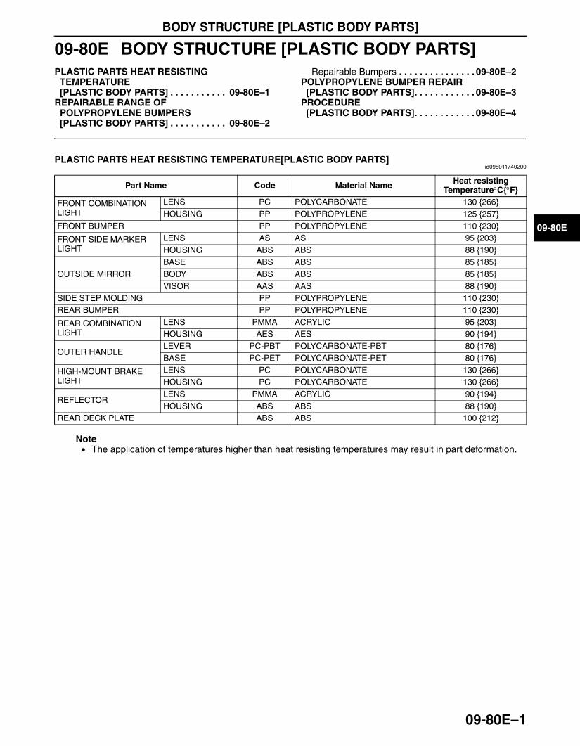
BODY STRUCTURE [PLASTIC BODY PARTS]
09-80E–1
09-80E
09-80E BODY STRUCTURE [PLASTIC BODY PARTS]PLASTIC PARTS HEAT RESISTING
TEMPERATURE[PLASTIC BODY PARTS] . . . . . . . . . . . 09-80E–1
REPAIRABLE RANGE OF POLYPROPYLENE BUMPERS[PLASTIC BODY PARTS] . . . . . . . . . . . 09-80E–2
Repairable Bumpers . . . . . . . . . . . . . . . 09-80E–2POLYPROPYLENE BUMPER REPAIR
[PLASTIC BODY PARTS]. . . . . . . . . . . . 09-80E–3PROCEDURE
[PLASTIC BODY PARTS]. . . . . . . . . . . . 09-80E–4
End of TocBM: PLASTIC BODY PARTSPLASTIC PARTS HEAT RESISTING TEMPERATURE[PLASTIC BODY PARTS]
id098011740200
Note• The application of temperatures higher than heat resisting temperatures may result in part deformation.
End Of SieBM: BUMPER
Part Name Code Material Name Heat resistingTemperature°C{°F}
FRONT COMBINATION LIGHT
LENS PC POLYCARBONATE 130 {266}HOUSING PP POLYPROPYLENE 125 {257}
FRONT BUMPER PP POLYPROPYLENE 110 {230}
FRONT SIDE MARKER LIGHT
LENS AS AS 95 {203}HOUSING ABS ABS 88 {190}
OUTSIDE MIRRORBASE ABS ABS 85 {185}BODY ABS ABS 85 {185}VISOR AAS AAS 88 {190}
SIDE STEP MOLDING PP POLYPROPYLENE 110 {230}REAR BUMPER PP POLYPROPYLENE 110 {230}
REAR COMBINATION LIGHT
LENS PMMA ACRYLIC 95 {203}HOUSING AES AES 90 {194}
OUTER HANDLELEVER PC-PBT POLYCARBONATE-PBT 80 {176}BASE PC-PET POLYCARBONATE-PET 80 {176}
HIGH-MOUNT BRAKE LIGHT
LENS PC POLYCARBONATE 130 {266}HOUSING PC POLYCARBONATE 130 {266}
REFLECTORLENS PMMA ACRYLIC 90 {194}HOUSING ABS ABS 88 {190}
REAR DECK PLATE ABS ABS 100 {212}
3426-1U-06F(09-80E).fm 1 ページ 2006年6月20日 火曜日 午後3時42分
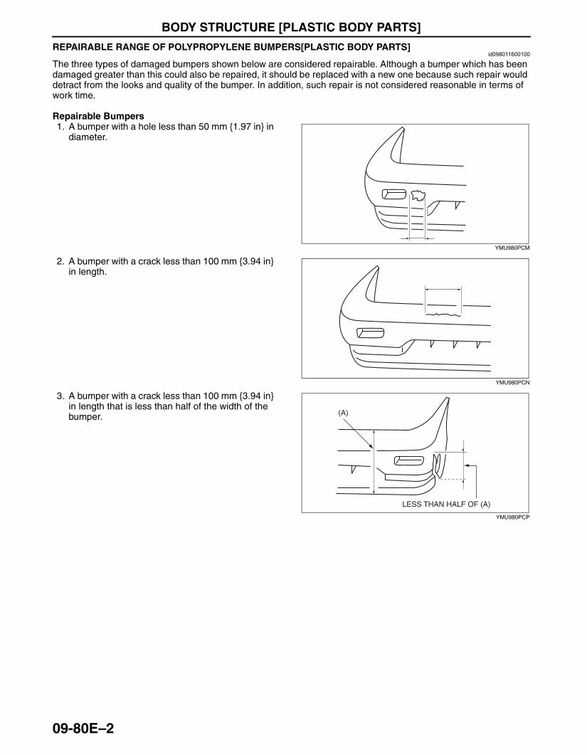
BODY STRUCTURE [PLASTIC BODY PARTS]
09-80E–2
REPAIRABLE RANGE OF POLYPROPYLENE BUMPERS[PLASTIC BODY PARTS]id098011600100
The three types of damaged bumpers shown below are considered repairable. Although a bumper which has been damaged greater than this could also be repaired, it should be replaced with a new one because such repair would detract from the looks and quality of the bumper. In addition, such repair is not considered reasonable in terms of work time.
Repairable Bumpers1. A bumper with a hole less than 50 mm {1.97 in} in
diameter.
2. A bumper with a crack less than 100 mm {3.94 in} in length.
3. A bumper with a crack less than 100 mm {3.94 in} in length that is less than half of the width of the bumper.
End Of Sie
YMU980PCM
YMU980PCN
LESS THAN HALF OF (A)
(A)
YMU980PCP
3426-1U-06F(09-80E).fm 2 ページ 2006年6月20日 火曜日 午後3時42分
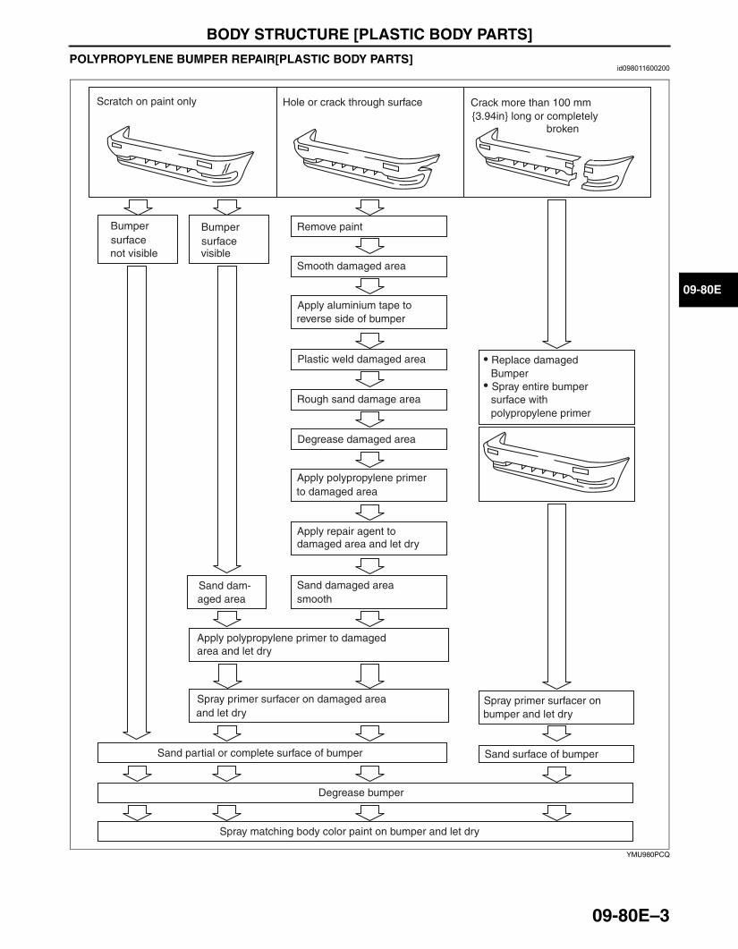
BODY STRUCTURE [PLASTIC BODY PARTS]
09-80E–3
09-80E
POLYPROPYLENE BUMPER REPAIR[PLASTIC BODY PARTS]id098011600200
End Of Sie
Scratch on paint only Hole or crack through surface Crack more than 100 mm{3.94in} long or completely
broken
Bumpersurface
Bumpersurfacenot visible visible
Remove paint
Smooth damaged area
Apply aluminium tape toreverse side of bumper
Plastic weld damaged area
Rough sand damage area
Degrease damaged area
Apply repair agent to damaged area and let dry
Sand damaged areasmooth
Sand dam-aged area
Apply polypropylene primer to damaged area and let dry
Spray primer surfacer on damaged areaand let dry
Spray primer surfacer onbumper and let dry
Sand surface of bumperSand partial or complete surface of bumper
Degrease bumper
Spray matching body color paint on bumper and let dry
Replace damagedBumperSpray entire bumpersurface withpolypropylene primer
Apply polypropylene primerto damaged area
YMU980PCQ
3426-1U-06F(09-80E).fm 3 ページ 2006年6月20日 火曜日 午後3時42分
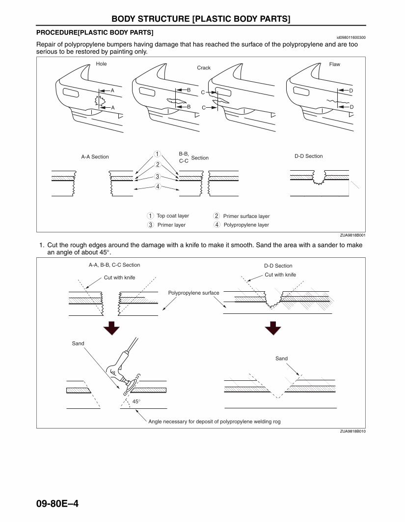
BODY STRUCTURE [PLASTIC BODY PARTS]
09-80E–4
PROCEDURE[PLASTIC BODY PARTS]id098011600300
Repair of polypropylene bumpers having damage that has reached the surface of the polypropylene and are too serious to be restored by painting only.
1. Cut the rough edges around the damage with a knife to make it smooth. Sand the area with a sander to make an angle of about 45°.
Hole
A
A
A-A Section
Crack
B
B
C
C
Flaw
D
D
B-B,C-C
Section D-D Section
Top coat layer
Primer layer
Primer surface layer
Polypropylene layer
4
4
3
3
1
1
2
2
ZUA9818B001
A-A, B-B, C-C Section
Cut with knife
Polypropylene surface
D-D Section
Cut with knife
Sand
Sand
Angle necessary for deposit of polypropylene welding rog
45°
ZUA9818B010
3426-1U-06F(09-80E).fm 4 ページ 2006年6月20日 火曜日 午後3時42分
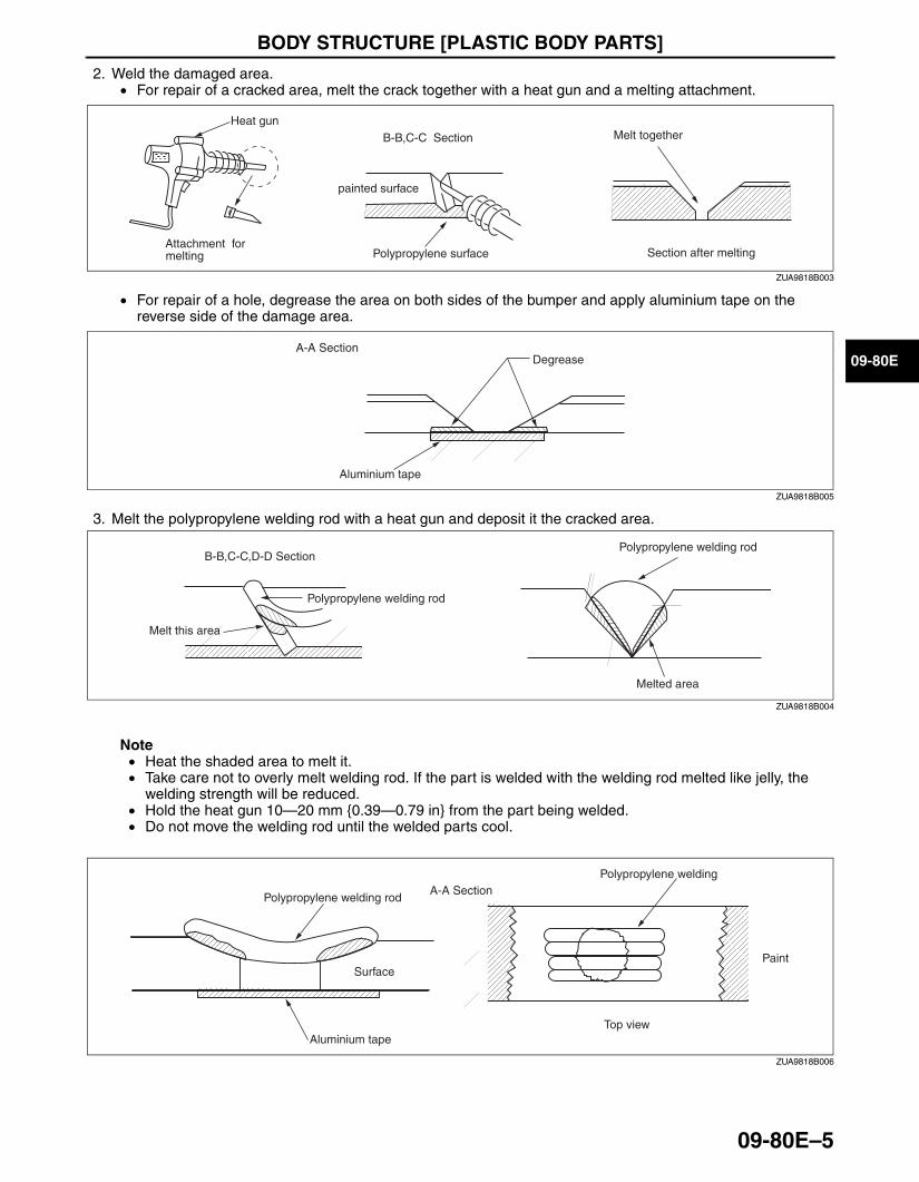
BODY STRUCTURE [PLASTIC BODY PARTS]
09-80E–5
09-80E
2. Weld the damaged area.• For repair of a cracked area, melt the crack together with a heat gun and a melting attachment.
• For repair of a hole, degrease the area on both sides of the bumper and apply aluminium tape on the reverse side of the damage area.
3. Melt the polypropylene welding rod with a heat gun and deposit it the cracked area.
Note• Heat the shaded area to melt it.• Take care not to overly melt welding rod. If the part is welded with the welding rod melted like jelly, the
welding strength will be reduced.• Hold the heat gun 10—20 mm {0.39—0.79 in} from the part being welded.• Do not move the welding rod until the welded parts cool.
Polypropylene surface
Heat gun
Attachment formelting
painted surface
Melt togetherB-B,C-C Section
Section after melting
ZUA9818B003
A-A SectionDegrease
Aluminium tape
ZUA9818B005
Polypropylene welding rod
Polypropylene welding rod
Melt this area
Melted area
B-B,C-C,D-D Section
ZUA9818B004
Polypropylene welding rod
Polypropylene welding
Paint
Top view
A-A Section
Surface
Aluminium tape
ZUA9818B006
3426-1U-06F(09-80E).fm 5 ページ 2006年6月20日 火曜日 午後3時42分

BODY STRUCTURE [PLASTIC BODY PARTS]
09-80E–6
4. Sand the surface of the polypropylene gradually as it is easily melted by the abrasion heat. Sand the area to which repair agent will be applied.
5. Uniformly apply polypropylene primer with a brush to an area larger than the repaired area. Allow to dry about 10 minutes at 20 °C {68 °F}.
6. Mix the main agent and the stiffening agent in a ratio of one to one. Apply the mixed repair agent to the damaged area.
Note• When mixing the main and stiffening agents, take care not to allow bubbles to form.• The repair agent hardens quickly (about 5 minutes); proceed with the work immediately after mixing the
agents.• Allow about 30 minutes to dry (20 °C {68 °F}) before sanding.
The repair agent is a two part epoxy adhesive.When the repair agent hardens, it will provide a good finish with the same flexibility as the polypropylens.The repair agent for a urethane bumper is also a two part adhesive compound. However, this is different from that for a polypropylene bumper. If the incorrect repair agent is used, the repair will be faulty.
Sand graduallySand repair area
Paint
YMU980PCX
Larger than repaired area
Polypropylene primer
YMU980PCY
Repair agentDo not mix air
Weld
Polypropylene surface
YMU980PCZ
3426-1U-06F(09-80E).fm 6 ページ 2006年6月20日 火曜日 午後3時42分

BODY STRUCTURE [PLASTIC BODY PARTS]
09-80E–7
09-80E
7. Sand the area with #180—240 sandpaper.
Note• If excessive force is applied to the area when sanding, the surface will be damaged.• If fuzz remains around the repaired area, melt it with a heat gun.
8. Degrease the painted surface.9. Mix the primer and the hardener at a ratio of one to one. Apply the primer to the repaired area and the surface
of the bumper with a brush or spray.
Use the primer within 16 hours after it is mixed.
Note• Polypropylene primer will dissolve even after drying if it is wiped with solvent. Use only water to clean
around the primer.
10. Allow the part to dry.
YMU980PD0
1 1
polypropylene primer Primer hardener
YMU980PD1
3426-1U-06F(09-80E).fm 7 ページ 2006年6月20日 火曜日 午後3時42分
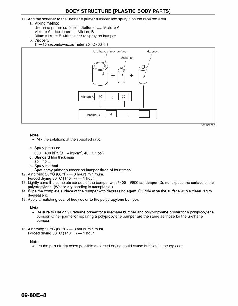
BODY STRUCTURE [PLASTIC BODY PARTS]
09-80E–8
11. Add the softener to the urethane primer surfacer and spray it on the repaired area.a. Mixing method
Urethane primer surfacer + Softener ..... Mixture AMixture A + hardener ..... Mixture BDilute mixture B with thinner to spray on bumper
b. Viscosity14—16 seconds/viscosimeter 20 °C {68 °F}
Note• Mix the solutions at the specified ratio.
c. Spray pressure300—400 kPa {3—4 kg/cm2, 43—57 psi}
d. Standard film thickness30—40 µ
e. Spray methodSpot-spray primer surfacer on bumper three of four times
12. Air drying 20 °C {68 °F} — 8 hours minimum.Forced drying 60 °C {140 °F} — 1 hour
13. Lightly sand the complete surface of the bumper with #400—#600 sandpaper. Do not expose the surface of the polypropylene. (Wet or dry sanding is acceptable.)
14. Wipe the complete surface of the bumper with degreasing agent. Quickly wipe the surface with a clean rag to degrease it.
15. Apply a matching coat of body color to the polypropylene bumper.
Note• Be sure to use only urethane primer for a urethane bumper and polypropylene primer for a polypropylene
bumper. Other paints for repairing a polypropylene bumper are the same as those for the urethane bumper.
16. Air drying 20 °C {68 °F} — 8 hours minimum.Forced drying 60 °C {140 °F} — 1 hour
Note• Let the part air dry when possible as forced drying could cause bubbles in the top coat.
End Of Sie
Urethane primer surfacer
Softener
Hardner
Mixture A
Mixture B
100 30
4 1
YMU980PD2
3426-1U-06F(09-80E).fm 8 ページ 2006年6月20日 火曜日 午後3時42分