Embed Size (px)
Citation preview
Volume 5, no. 1 (April, 2010) ISSN 1913-133X
Contents of this issue ...Bifurcation Analysis and Chaos Detection in Power Systems
S. Grillo, University of Genova – Intelligent Electric Energy Systems Laboratory [email protected]
S. Massucco, University of Genova – Intelligent Electric Energy Systems Laboratory [email protected]
A. Morini, University of Genova – Intelligent Electric Energy Systems Laboratory [email protected]
A. Pitto, University of Genova – Intelligent Electric Energy Systems Laboratory [email protected]
F. Silvestro, University of Genova – Intelligent Electric Energy Systems Laboratory [email protected]
Modeling and Application of VSC-HVDC in the European Transmission System
A. L’Abbate, Power Systems Development Department, ENEA – Ricerca sul Sistema Elettrico (ERSE), Milan, Italy [email protected]
G. Fulli, Institute for Energy, 1 DG Joint Research Centre – European Commission, Petten, The Netherlands [email protected]
Optimal Combined Overcurrent and Distance Relays Co-ordination Using a New Genetic Algorithm Method
Somayeh.Sadat.Hashemi.Kamangar, MSc. Student, Department of Electrical Engineering, Amirkabir University of Technology, Tehran, Iran [email protected]
Hossein.Askarian.Abyaneh, Professor, Department of Electrical Engineering, Amirkabir University of Technology, Tehran, Iran [email protected]
Farzad.Razavi, Assistant Professor, Department of Electrical Engineering, Tafresh University, Tafresh, Iran [email protected]
Reza.Mohammadi.Chabanloo, PhD. Student, Department of Electrical Engineering, Amirkabir University of Technology, Tehran, Iran [email protected]
®
®
®

Comparative Study on the Properties of Porcelain and Epoxy Resin Insulators taken from a Coastal Area in Indonesia
Waluyo, Doctoral Student, School of Electrical Engineering and Informatics, Bandung Institute of Technology (ITB), Jl. Ganesha No. 10 Bandung 40132 Indonesia [email protected]
Ngapuli I. Sinisuka, Academic Staff, School of Electrical Engineering and Informatics, Bandung Institute of Technology (ITB), Jl. Ganesha No. 10 Bandung 40132 Indonesia
Suwarno, Academic Staff, School of Electrical Engineering and Informatics, Bandung Institute of Technology (ITB), Jl. Ganesha No. 10 Bandung 40132 Indonesia
Maman A. Djauhari, Academic Staff, Faculty of Mathematics and Natural Science, Bandung Institute of Technology (ITB), Jl. Ganesha No. 10 Bandung 40132 Indonesia
Wireless Solar Energy to Homes: A Magnetic Resonance Approach
Steven A. Hackworth, Department of Electrical & Computer Engineering, University of Pittsburgh, Pittsburgh, PA 15261 USA [email protected]
Xiaoyu Liu, Department of Electrical & Computer Engineering, University of Pittsburgh, Pittsburgh, PA 15261 USA [email protected]
Chengliu Li, Department of Electrical & Computer Engineering, University of Pittsburgh, Pittsburgh, PA 15261 USA [email protected]
®
®
MODELING AND APPLICATION OF VSC-HVDC IN THE EUROPEAN TRANSMISSION SYSTEM
A. L'Abbate G. Fulli
[email protected] [email protected]
Power Systems Development Department Institute for Energy ENEA – Ricerca sul Sistema Elettrico (ERSE)1 DG Joint Research Centre – European Commission
Milan, Italy Petten, The Netherlands
1 former CESI RICERCA
Abstract – The present paper focuses on the technical, environmental, and economic features of VSC-based HVDC technologies. The aim is to investigate the impact of VSC-HVDC on the European power system: specific at-tention is paid to the transmission capacity enhancement attainable in targeted applications. Towards this purpose, an original steady state model of the VSC-HVDC is pre-sented and tested. Then, a techno-economic analysis of the impact of VSC-HVDC on liberalized power systems in Europe is undertaken so as to investigate the feasibility and the sustainability of such investment, also compared to building HVAC lines.
Keywords: analysis of investments, European power system liberalization, VSC-HVDC, power flow analy-sis, steady state modeling, transmission capacity en-hancement, transmission planning
1 INTRODUCTION
The electric power systems are generally experienc-ing different trends which may imply major changes in both their architecture and operation.
In Europe, against a background of energy market restructuring, increasing environmental awareness and rising concerns about security of energy supply, the electric power grid is facing several issues.
Indeed, due to a general increase of inter- and intra-zonal power transactions, the transmission network in some areas operates close to its physical limits [1]. Furthermore, the constant growth in electricity demand in Europe can put the electric system under strain. Such issues have been traditionally addressed by adding new capacity, with investments particularly in the field of large-size generation and High Voltage Alternating Current (HVAC) transmission infrastructures.
Nowadays, increasing the power system capacity is frequently a challenging option due to economic, envi-ronmental, and political constraints that hinder the con-struction of large power plants and high voltage lines. To address the above issues new solutions are therefore sought necessary. Among them, one of the most promis-ing foresees the targeted deployment of HVDC (High Voltage Direct Current) transmission technologies dis-placing the conventional HVAC ones [2][3]. The land use and the environmental impact as a whole may be smaller with HVDC compared to HVAC technology.
In any case, a techno-economic assessment needs to be carefully carried out by taking into account the rele-vant attached cost and benefit elements. HVDC is a well established technology and presents characteristics that have made it widely attractive over AC transmission for specific applications like long-distance power transmis-sion, long submarine cable links and interconnection of asynchronous systems [2][3].
Currently, recent advances in the power electronics, coupled to the traditional features of HVDC, may lead to improve the operation and sustain the development of the European transmission grid. In fact, the application of VSC (Voltage Source Converter)-based HVDC can provide the European power system with an increased transmission network capacity and generally enhanced system reliability, security and controllability [3]-[5]. These properties are especially important in a deregu-lated environment: VSC-HVDC with its fast power flow control capability can be an attractive option to efficiently and timely avoid or relieve network con-straints, thus reducing the need for building new HVAC lines.
The present paper aims at investigating the impact of VSC-HVDC on the European power system, focusing on the technical, environmental, and economic features of these devices. Specific attention is paid to the trans-mission capacity enhancement attainable by VSC-HVDC in targeted applications in the European power system. Towards this scope, modeling VSC-HVDC technologies for steady-state studies becomes essential. A techno-economic analysis of the impact of VSC-HVDC on liberalized power systems in Europe is also undertaken to investigate the feasibility and the sustai-nability of such investment, also compared to other alternatives such as building or replacing AC lines.
In this paper, Section 2 presents the main technical features of VSC-HVDC. Section 3 introduces an origi-nal VSC-HVDC Power Injection Model (PIM) suitable for load flow studies. Section 4 deals with the introduc-tion of VSC-HVDC economic and environmental fea-tures. Section 5 first presents load flow test results suc-cessfully validating the features of PIM. Finally, the outcomes of practical test cases towards a techno-economic assessment of VSC-HVDC are shown. Focus is particularly on the enhancement of cross-border
International Journal of Innovations in Energy Systems and Power (Vol. 5 no. 1, April 2010) 8 of 44
transmission capacity in a European regional market system.
2 TECHNICAL FEATURES OF VSC-HVDC The traditional HVDC technology has been deployed
especially for overhead bulk power transmission over long distances and undersea cable connection. The HVDC links present in Europe are mostly submarine cables connecting various power system portions sepa-rated by sea (e.g. Scandinavia - mainland Europe, UK - France, UK - Ireland, Italy - Greece). Indeed, for over-head transmission, the HVAC lines have so far offered a more viable techno-economic solution with respect to HVDC to cover small and medium distances (below some hundred km) [2][3]. An innovative HVDC technology - based on Voltage Source Converters (VSCs) and therefore called VSC-HVDC - has been recently applied not only to overcome critical issues hindering the upgrading/construction of HVAC lines but also to increase the robustness of the transmission system. VSC-HVDC units currently range from a few tens of MW to several hundreds (up to a thousand) of MW and can reach ±300 kV voltages. The most recent installation of VSC-HVDC in Europe has been the submarine link between Finland and Estonia (Estlink) [5], while more projects are ongoing/planned; also, plans for overland installation start to be discussed in several countries.
The characteristics of VSC-HVDC have been recent-ly investigated in open literature ([3]-[5],[6][7] among others). The key advantages of VSC-HVDC, in com-parison with the classic HVDC based on Current Source Converters (CSCs) are described in [3]-[5].
Flexibility and range of power control. VSC-HVDC can control both active and reactive power independent-ly, differently from classic HVDC, and generate or consume reactive power within a wider range than HVDC by a very rapid control action. This is because VSC-HVDC converter stations employ state-of-the-art power semiconductors such as Gate Turn-Off (GTO) Thyristors, Insulated Gate Bipolar Transistors (IGBT), and Integrated Gate Commutated Thyristors (IGCT), which are also capable to turn off the current. The VSC-HVDC makes it possible to create almost instantaneous-ly any voltage phase angle or amplitude. Both stations can independently generate or consume reactive power. Unlike conventional HVDC converters, which normally have a 5% minimum current, the VSC-HVDC can oper-ate even at zero active power and in this situation still provide the full range of reactive power. The power reversal is obtained by changing the direction of the direct current (DC) and not by changing the DC voltage as for conventional HVDC.
Compactness and modularity of converter stations. VSC-HVDC is based on a modular concept with stan-dardized sizes for the converter stations. Conventional HVDC is generally tailor-made to suit specific applica-tions. Compared with the classic HVDC station, the
converter station with VSC is more compact and has a smaller footprint. Modular systems can be installed in different stages to meet the capacity demand.
Easier expansibility to multiterminal configurations. In contrast to conventional HVDC, with VSC-HVDC it is easier to connect substations to a generic point of the line, whereby getting a DC line with multiple terminals. The costs are those of a single converter per tapping. Costs are naturally lower when the new substation is not sized to carry the full load. Compared to CSCs, the VSC technology facilitates the connection of several conver-ters to a common bipolar DC bus since the voltage po-larity is not reversed when changing the power direc-tion.
Naturally, the VSC-HVDC technology presents also some drawbacks when compared to HVDC and the main ones are portrayed in the following. VSC-HVDC technology is more expensive than
traditional HVDC, basically due to the higher cost of the converter stations.
VSC-HVDC technology displays higher converter losses than traditional HVDC (some 1-2% of sys-tem rated power). Consequently, for a given trans-mission capacity, the cable length that equals the AC Overhead Line (OHL) systems losses (the so-called break-even distance) is higher than that for HVDC.
VSC-HVDC is by nature bipolar since the DC circuit is not connected to ground. Differently from traditional bipolar HVDC, VSC-HVDC has no pos-sibility to execute emergency power transfer via one pole when the other pole trips.
DC line-to-ground faults are more critical with VSC-HVDC than with CSC-HVDC.
However, considering the intrinsic features of VSC-HVDC and the steady advances in such technological field, it is expected that some disadvantages can be quickly scaled down and others overcome.
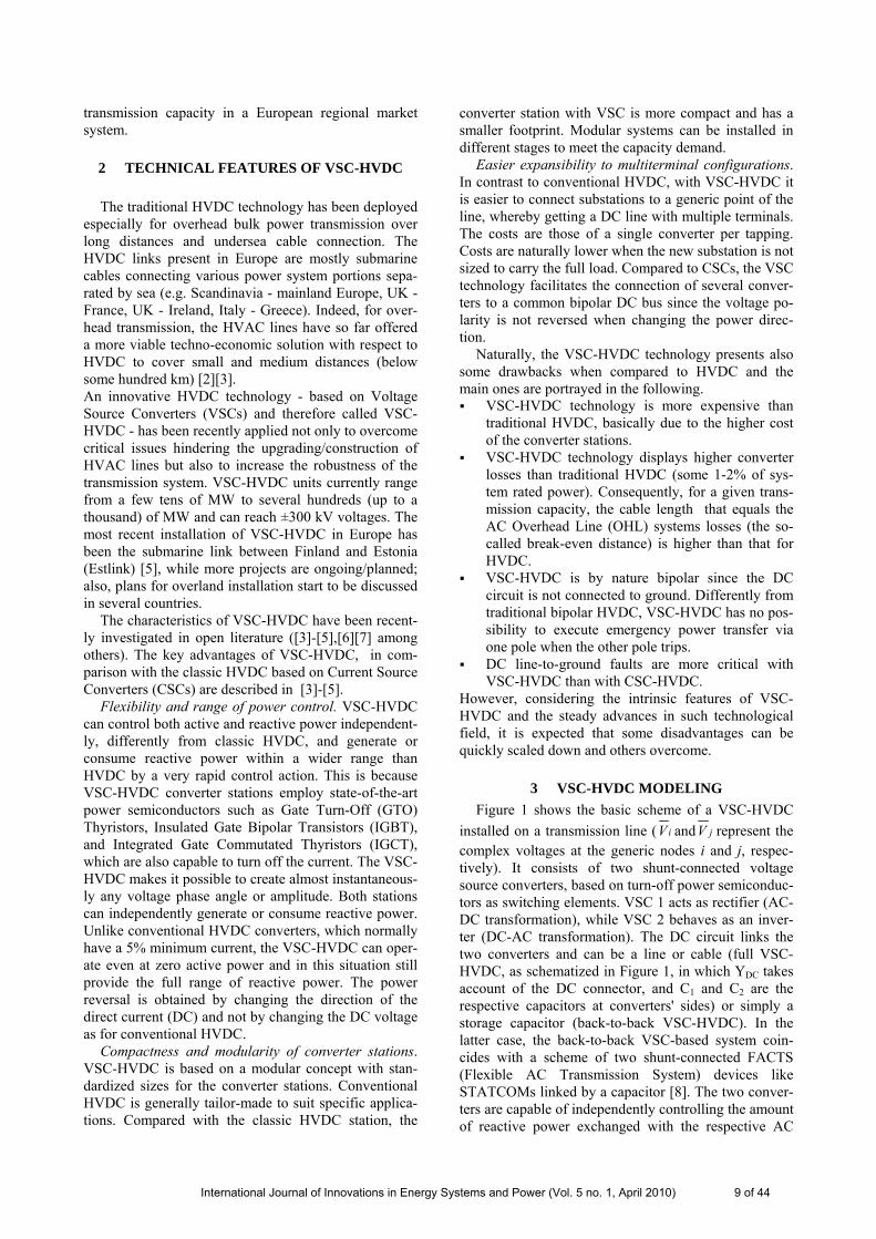
3 VSC-HVDC MODELING Figure 1 shows the basic scheme of a VSC-HVDC
installed on a transmission line ( iV and jV represent the complex voltages at the generic nodes i and j, respec-tively). It consists of two shunt-connected voltage source converters, based on turn-off power semiconduc-tors as switching elements. VSC 1 acts as rectifier (AC-DC transformation), while VSC 2 behaves as an inver-ter (DC-AC transformation). The DC circuit links the two converters and can be a line or cable (full VSC-HVDC, as schematized in Figure 1, in which YDC takes account of the DC connector, and C1 and C2 are the respective capacitors at converters' sides) or simply a storage capacitor (back-to-back VSC-HVDC). In the latter case, the back-to-back VSC-based system coin-cides with a scheme of two shunt-connected FACTS (Flexible AC Transmission System) devices like STATCOMs linked by a capacitor [8]. The two conver-ters are capable of independently controlling the amount of reactive power exchanged with the respective AC
International Journal of Innovations in Energy Systems and Power (Vol. 5 no. 1, April 2010) 9 of 44
node, and then the local AC bus voltage magnitude. Both converters linked by the DC circuit are also able to control the active power exchanged with the respective AC node, but only one of the two (so-called primary or master converter) can provide independent active power control, being then the other one (so-called secondary or slave converter) constrained to keep the DC power balance [6][7]. In Figure 1 Pq1
spec, Qq1spec, and Pq2
spec, Qq2
spec, are the specified active and reactive power to be exchanged from each converter, respectively VSC 1 and VSC 2, at the AC output: they define the output voltage angle and magnitude generated by each converter. Īi Īj
Īq1
C1
DC linkVSC 1
Qq1specPq1
spec Pq2spec Qq2
spec
1qV
iV
+VDC1
YDC
C2 +VDC2
VSC 2
Īq2
2qV
jV
Figure 1: A basic scheme of full VSC-HVDC.
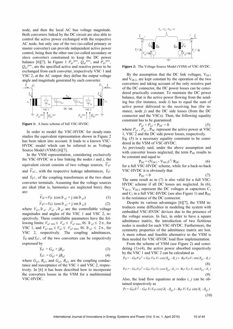
In order to model the VSC-HVDC for steady-state studies the equivalent representation shown in Figure 2 has been taken into account. It leads to a known VSC-HVDC model which can be referred to as Voltage Source Model (VSM) [6][7].
In the VSM representation, considering exclusively the VSC-HVDC in a line linking the nodes i and j, the equivalent circuit consists of two voltage sources, 1qV and 2qV , with the respective leakage admittances, 1qY& and 2qY& , of the coupling transformers at the two shunt converter terminals. Assuming that the voltage sources are ideal (that is, harmonics are neglected here), they are:
1 1 qq VV = (cosϑ q1 + j sinϑ q1) (1) 2 2 qq VV = (cosϑ q2 + j sinϑ q2) (2)
where Vq1,ϑ q1 ,Vq2 ,ϑ q2 are the controllable voltage magnitudes and angles of the VSC 1 and VSC 2, re-spectively. These controllable parameters have the fol-lowing limits: Vq1 min ≤ Vq1 ≤ Vq1 max, 0≤ ϑ q1 ≤ 2 π , for VSC 1, and Vq2 min ≤ Vq2 ≤ Vq2 max, 0≤ ϑ q2 ≤ 2 π , for VSC 2, respectively. The coupling admittances,
1qY& and 2qY& , of the two converters can be respectively expressed by 1qY& = Gq1 + jBq1 (3) 2qY& = Gq2 + jBq2 (4) where Gq1, Bq1, and Gq2, Bq2, are the coupling conduc-tance and susceptance of the VSC 1 and VSC 2, respec-tively. In [6] it has been described how to incorporate the converters losses in the VSM for a multiterminal VSC-HVDC.
Īi
Vi< Vq1<
Vj <
Ījij
Īq1
1qϑjϑiϑ
1qY& Īq2
2qϑ
2qY&
Vq2<
Pq1 + Pq2 + PDC = 0
Figure 2: The Voltage Source Model (VSM) of VSC-HVDC.
By the assumption that the DC link voltages, VDC1 and VDC2, are kept constant by the operation of the two converters and taking account of the only resistive part of the DC connector, the DC power losses can be consi-dered practically constant. To maintain the DC power balance, that is the active power flowing from the send-ing bus (for instance, node i) has to equal the sum of active power delivered to the receiving bus (for in-stance, node j) and the DC side losses (from the DC connector and the VSCs). Then, the following equality constraint has to be guaranteed:
Pq1 + Pq2 + PDC = 0 (5) where Pq1 , Pq2 , PDC represent the active power at VSC 1, VSC 2 and the DC side power losses, respectively. Eq. (5) is a necessary equality constraint to be consi-dered in the VSM of VSC-HVDC. As previously said, under the above assumption and with converter losses neglected, the term PDC results to be constant and equal to
PDC = (VDC1 - VDC2) 2/ RDC (6)
for a full VSC-HVDC scheme, while for a back-to-back VSC-HVDC it is obviously that
PDC = 0 (7) The same result as in (7) is also valid for a full VSC-HVDC scheme if all DC losses are neglected. In (6), VDC1, VDC2 represent the DC voltages at capacitors C1 and C2 in a full VSC-HVDC (see also Figure 1) and RDC is the resistance of the DC connector.
Despite its various advantages [6][7], the VSM in-troduces some difficulties in modeling the system with embedded VSC-HVDC devices due to the presence of the voltage sources. In fact, in order to have a square admittance matrix, the introduction of two fictitious nodes is needed for each VSC-HVDC. Furthermore, the symmetry properties of the admittance matrix are lost. A more robust and feasible alternative to the VSM is then needed for VSC-HVDC load flow implementation.
From the scheme of VSM (see Figure 2) and consi-dering (1)-(4), the active power absorbed respectively by the VSC 1 and VSC 2 can be calculated as
) - sin(VV B ) - cos(VVG VG -=P iq i q qiqi q qq qq ϑϑϑϑ 1111112111 ++
(8) ) - sin(VV B )- cos(VVG VG -=P jq j q qjqj q qq qq ϑϑϑϑ 2222222222 ++
(9) Also, the load flow equations at nodes i, j can be ob-tained respectively as
) - sin(VV- B ) - cos(VV- G VG =P qi qi qqi qi qi qi 11111121 ϑϑϑϑ
(10)
International Journal of Innovations in Energy Systems and Power (Vol. 5 no. 1, April 2010) 10 of 44
) - cos(VVB ) - sin(VV- GVB- =Q qi qi qqi qi qi qi 11111121 ϑϑϑϑ +
(11) ) - sin(VV- B ) -cos(VV- G VG =P qj qj qqj qj qj qj 22222222 ϑϑϑϑ
(12) ) - cos(VVB ) - sin(VV- GVB- =Q qj qj qqj qj qj qj 22222222 ϑϑϑϑ +
(13) The eq. (10) can be written as
Pi = Gq1Vi2 – Pi
VSC (14) with Pi
VSC = ) sin( ) cos( 1 11111 qiqi qqi qi q -VV B-VVG ϑϑϑϑ + (15) where Pi
VSC represents the active power injection of the VSC 1 at node i. The other term in (14) takes the real power contribution into account as of a passive two-node component. Analogously, the eqs. (11)-(13) give the expressions of the VSC 1 reactive power injection at node i, Qi
VSC, and the VSC 2 real and reactive power injections at node j, Pj
VSC and QjVSC, respectively. They
result to be: Qi
VSC = ) cos( ) sin( 1 11111 qiqi qqi qi q -VVB-VV G ϑϑϑϑ − (16) Pj
VSC= ) sin( ) cos( 2 22222 qjqj qqj qj q -VVB-VVG ϑϑϑϑ + (17) Qj
VSC= ) cos( ) sin( 2 22222 qjqj qqj qj q -VVB-VVG ϑϑϑϑ − (18) The equality constraint in (5), by the expressions of Pq1, Pq2 in (8), (9), gives
+++
+++
) sin( ) cos( -
) sin( ) cos( -
2 2 22 2222 2
1 1 11 1121 1
jqjqqjqj q qqq
iqiqqiqi q qqq
-VVB-VVGVG
-VV B-VVGVG
ϑϑϑϑ
ϑϑϑϑ
+ PDC = 0 (19) It can be shown that (19) is equivalent to
PiVSC + Pj
VSC- PDC = 0 (20) by assuming
Gq1 = Gq2 = 0 (21) The relation (21) means that the impedances of the
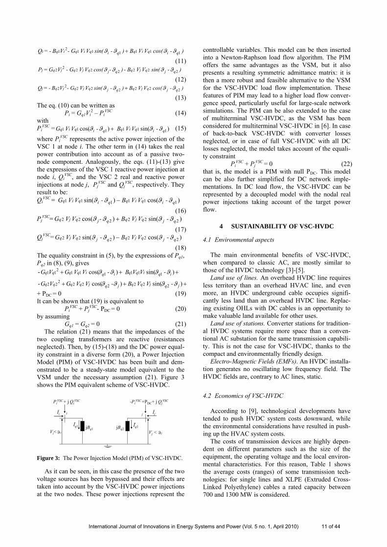
two coupling transformers are reactive (resistances neglected). Then, by (15)-(18) and the DC power equal-ity constraint in a diverse form (20), a Power Injection Model (PIM) of VSC-HVDC has been built and dem-onstrated to be a steady-state model equivalent to the VSM under the necessary assumption (21). Figure 3 shows the PIM equivalent scheme of VSC-HVDC.
Īi
Vi< Vj <
Īji j
Īq1
jϑiϑ
Īq2jBq1
PiVSC + j Qi
VSC
jBq2
-PiVSC +PDC+ j Qj
VSC
Figure 3: The Power Injection Model (PIM) of VSC-HVDC.
As it can be seen, in this case the presence of the two voltage sources has been bypassed and their effects are taken into account by the VSC-HVDC power injections at the two nodes. These power injections represent the
controllable variables. This model can be then inserted into a Newton-Raphson load flow algorithm. The PIM offers the same advantages as the VSM, but it also presents a resulting symmetric admittance matrix: it is then a more robust and feasible alternative to the VSM for the VSC-HVDC load flow implementation. These features of PIM may lead to a higher load flow conver-gence speed, particularly useful for large-scale network simulations. The PIM can be also extended to the case of multiterminal VSC-HVDC, as the VSM has been considered for multiterminal VSC-HVDC in [6]. In case of back-to-back VSC-HVDC with converter losses neglected, or in case of full VSC-HVDC with all DC losses neglected, the model takes account of the equali-ty constraint
PiVSC + Pj
VSC = 0 (22)
that is, the model is a PIM with null PDC. This model can be also further simplified for DC network imple-mentations. In DC load flow, the VSC-HVDC can be represented by a decoupled model with the nodal real power injections taking account of the target power flow.
4 SUSTAINABILITY OF VSC-HVDC
4.1 Environmental aspects The main environmental benefits of VSC-HVDC,
when compared to classic AC, are mostly similar to those of the HVDC technology [3]-[5].
Land use of lines. An overhead HVDC line requires less territory than an overhead HVAC line, and even more, an HVDC underground cable occupies signifi-cantly less land than an overhead HVDC line. Replac-ing existing OHLs with DC cables is an opportunity to make valuable land available for other uses.
Land use of stations. Converter stations for tradition-al HVDC systems require more space than a conven-tional AC substation for the same transmission capabili-ty. This is not the case for VSC-HVDC, thanks to the compact and environmentally friendly design.
Electro-Magnetic Fields (EMFs). An HVDC installa-tion generates no oscillating low frequency field. The HVDC fields are, contrary to AC lines, static.
4.2 Economics of VSC-HVDC According to [9], technological developments have
tended to push HVDC system costs downward, while the environmental considerations have resulted in push-ing up the HVAC system costs.
The costs of transmission devices are highly depen-dent on different parameters such as the size of the equipment, the operating voltage and the local environ-mental characteristics. For this reason, Table 1 shows the average costs (ranges) of some transmission tech-nologies: for single lines and XLPE (Extruded Cross-Linked Polyethylene) cables a rated capacity between 700 and 1300 MW is considered.
International Journal of Innovations in Energy Systems and Power (Vol. 5 no. 1, April 2010) 11 of 44
In Table 1 the investment costs of the station compo-nents are referred to the throughput power. This has been done also for a FACTS component like the Uni-fied Power Flow Controller (UPFC), having a power rating equal to a fraction (here assumed equal to 0.5) of the line’s throughput rating.
The cost of a VSC-HVDC link may be close to the one of an overhead line if all factors are taken into ac-count. For example, the higher costs attached to VSC stations installation and operation should be assessed against the substantial advantages in terms of power flow controllability. In other terms, a VSC-HVDC sys-tem should be more properly compared to an HVAC line equipped with fast power flow control devices (like the UPFC).
HVAC and HVDC Transmission lines Cost Unit
HVAC overhead single circuit line 200-500 kEUR/km
HVAC overhead double circuit line 300-700 kEUR/km
HVDC overhead bipolar line 200-400 kEUR/km
HVDC XLPE underground cable 1000-2500 kEUR/km HVDC Converter stations
and FACTS Cost Unit
Traditional HVDC converter 40-60 kEUR/MVA
VSC-HVDC converter 50-70 kEUR/MVA
UPFC 50-90 kEUR/MVA Table 1: Average investment costs of transmission technolo-gies (Sources [9]-[12]).
In case the transmission of a higher level of power between two zones is of concern, planning the utilisa-tion of VSC-based HVDC devices may represent a possible solution.
The following advantages - deriving from the inser-tion of VSC-HVDC devices in the grid - are in the pre-sent analysis converted in economic benefits:
transmission capacity enhancement, monetized in terms of increased amount of cheaper energy im-ported by a zone or country with a higher electricity wholesale price;
relief of congestions.
VSC-HVDC devices offer also other advantages, which are here not translated in economic revenues. These may include: cancellation, postponement or downsizing of other planned investments; electricity loss reduction; relief of more efficient generation units constrained by network bottlenecks; avoid-ance/reduction of outages; support to reactive power and voltage control; avoidance/reduction of undesired power flows; avoidance/reduction of non supplied en-ergy.
When comparing the costs and benefits of AC and DC transmission systems, the willingness to bear a higher cost to reduce the visual/territorial impact of infrastructures (not always correlated with the reduction of EMF values) should be properly estimated.
Instead of a HVDC line, other solutions may envis-age the deployment of conventional components, such as new HVAC lines, mechanically-switched capacitors, tap-changers.
The comparison and prioritisation of alternative solu-tions (e.g. a conventional component versus a VSC-HVDC) is performed via cost-benefit analyses based on the following indicators: Net Present Value (NPV) of an investment Internal Rate of Return (IRR) of the invested capi-
tal Cost-Benefit Ratio or Profitability Index (PI) Pay Back Period (PBP) of an investment
All these four indicators are used to techno-economically assess the insertion of VSC-HVDC in the liberalised European power system [13]. To evaluate the economic benefits stemming from VSC-HVDC dep-loyment, the cash revenues are calculated as savings derived by an increased cheaper energy flow in the importing power system. These revenues can be ex-pressed in this case as
CR = NTCh ΔΔλ (23)
where Δλ is the electricity price differential between the importing and the exporting system, ΔNTC is the en-hancement of transmission capacity available in secure conditions and granted by the VSC-HVDC installation, and h is the number of yearly operation hours of the link between the two systems. For a simple formulation of the cash revenues CR as in (23), h and Δλ have been assumed as invariant with respect to the investment. The Net Transfer Capacity (NTC) differs from the Total Transfer Capability (TTC) by a security margin, the Transmission Reliability Margin (TRM) [14][15].
5 TEST RESULTS In this Section the results of various network imple-
mentations with VSC-HVDC models are presented. Load flow simulations have been carried out in Mat-lab®.
5.1 VSC-HVDC Modeling: 3-node network test cases For the first implementations a small network [7]
consisting of 3 nodes and 3 lines has been chosen for load flow tests of the VSC-HVDC models. The goal is to compare the results obtained by implementing the PIM with those ones by the VSM presented in [7]. A lossless, back-to-back VSC-HVDC has been inserted into the line A-C with the objective to control power flow towards bus A at 12.11 MW + j 0.2 MVAR and the voltage magnitude at bus C at 1.0 p.u. In this case, an additional node, D, is needed to connect the VSC-HVDC and the device is actually on the line D-C. Uti-lizing the VSC-HVDC parameters rates ( 1qY& = 2qY& =-j/0.1 p.u., 0.9 p.u. ≤ Vq1 ≤ 1.1 p.u., 0.9 p.u. ≤ Vq2 ≤ 1.1 p.u.) as in [7], the load flow results obtained by imple-menting both the models, VSM and PIM, are identical.
International Journal of Innovations in Energy Systems and Power (Vol. 5 no. 1, April 2010) 12 of 44
Newton-Raphson load flow convergence has been achieved to a tolerance of 10-12, within the same number of iterations and speed, by both VSM and PIM. Table 2 and Table 3 show the bus voltages and VSC-HVDC variables’ values, respectively, obtained by both the VSM and the PIM.
Bus A B C D V (p.u.) 1.000 1.000 1.000 1.016 ϑ (deg.) 4.83 0.0 -1.62 6.34
Table 2: Bus complex voltages by VSM and PIM.
By the PIM the VSC-HVDC real and reactive power injections at nodes D and C result to be equal to 12.11 MW, 1032.0 MVAR, and -12.11 MW, 1016.7 MVAR, respectively. As the results coincide with those ones in [7], the tables confirm the equivalence among the two steady-state models, VSM and PIM, in the lossless case. Furthermore, all the advantages given by the VSM are present in the PIM, but the PIM offers a greater robust-ness and feasibility.
Voltage Power rates (shunt)
Vq1 (p.u.) ϑ q1 (deg.) Pq1 (MW) Qq1 (MVAR)
1.016 7.01 12.11 0.34 Vq2 (p.u.) ϑ q2 (deg.) Pq2 (MW) Qq2 (MVAR)
1.017 -2.29 -12.11 17.12 Table 3: VSCs variables’ values by VSM and PIM.
In the same 3-node network as in [7], a full VSC-HVDC link is now considered between nodes A and C, with a fixed VDC1 and RDC set at 0.08 p.u. The VSC-HVDC parameters and control targets are the same as in the previous case. The load flow results obtained by PIM equal those ones by VSM, with the same conver-gence speed and number of iterations. This confirms the validity and properties of PIM also for full VSC-HVDC.
5.2 VSC-HVDC Modeling: IEEE 118-bus network
The effects of the insertion of VSC-HVDC in the IEEE 118-bus system [16] are here shown along with the results by the two models.
A lossless, back-to-back VSC-HVDC (hav-ing 1qY& = 2qY& =-j/0.1 p.u., 0.9 p.u. ≤ Vq1 ≤ 1.1 p.u., 0.9 p.u. ≤ Vq2 ≤ 1.1 p.u.) has been located into the line between the nodes 95 and 96: the scope is to maintain active and reactive power flows, leaving the VSC-HVDC towards bus 96, at 40 MW and 20 MVAR, re-spectively, and to control voltage magnitude at node 95 at 1.0 p.u. The VSC-HVDC is then actually placed between node 95 and the additional node, 119. Newton-Raphson load flow convergence has been reached (to-lerance of 10-12) by VSM and PIM implementations; the VSC-HVDC targets have been achieved and the results confirm the equivalence of the two models (active losses neglected). Table 4 shows the VSC-HVDC ef-fects in the IEEE 118-bus system. The greater robust-
ness and feasibility offered by PIM lead to better con-vergence speed performances by the PIM respect to those ones by VSM.
Without VSC-HVDC With VSC-HVDCMag. Voltage bus 95 0.980 p.u. 1.000 p.u. Power flows 95-96 -1.38 MW–j21.69 MVAR -
Power flows 119-96 - 40.0 MW +j 20.0 MVAR Table 4: VSC-HVDC effects in the IEEE 118-bus system.
5.3 VSC-HVDC in the European transmission system A techno-economic assessment of the insertion of
VSC-HVDC devices to locally enhance the transmis-sion capacity in the European power system is here presented. This analysis is based on load flow imple-mentation results, which have been then utilised for the calculation of the economic indicators (seen in Section 4) needed for assessing an investment in VSC-HVDC.
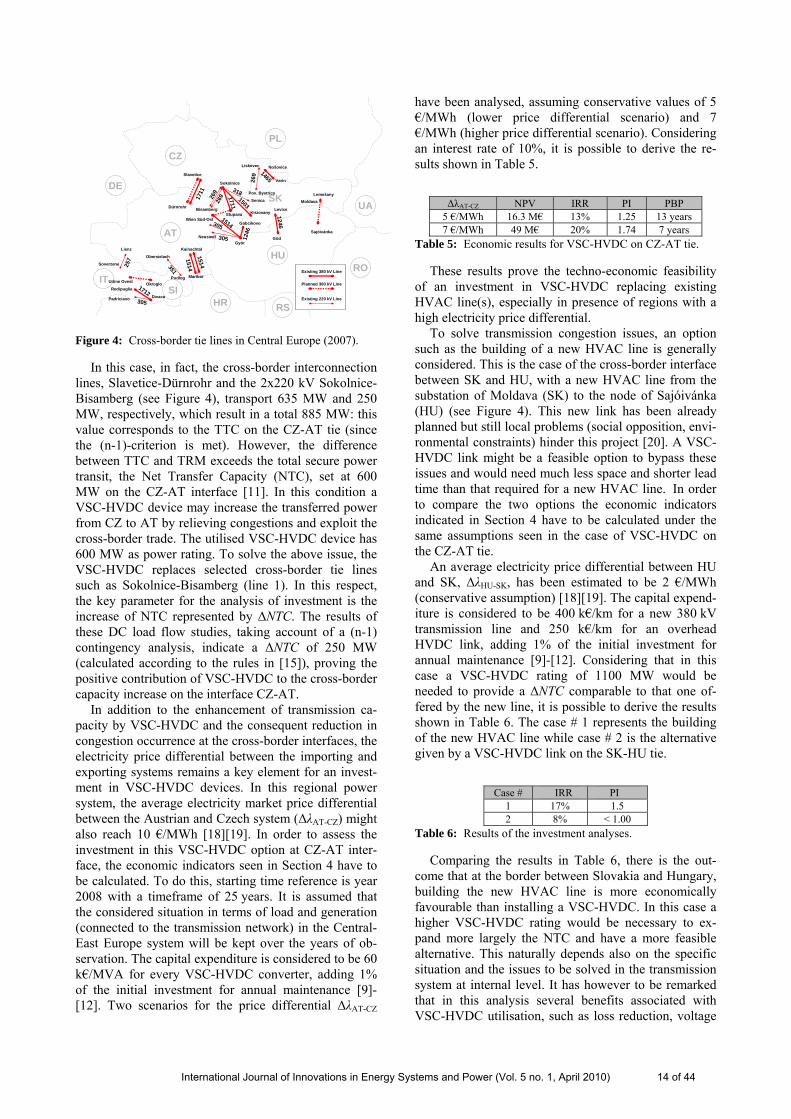
Reference system is the 400-220 kV European transmission grid. The test network, to be run for DC load flow studies, is the one described in [17], which gives a good approximation of the real Continental Europe (former UCTE) network (as of 16 Jan. 2002, at 11h00, in winter peak situation), particularly for cross-border flows. This system complemented by and up-dated with most recent data for the line capacity limits available from [14], consists of 1254 buses, 378 genera-tors and 1944 lines [13]. Attention has been paid espe-cially to the regional power transmission system and cross-border ties of Central-East Europe (comprising the networks of Germany, Austria, Poland, Czech Rep., Slovakia, Hungary and Slovenia) [18]. In particular, focus is on the links of Czech Republic (CZ), Slovakia (SK), Austria (AT) and Hungary (HU), where more network corridors are very frequently congested [14][15]. Figure 4 depicts a schematic representation of this part of the test network with the respective cross-border capacity limits (as of 2007) [13]. A TRM of 200 MW has been considered for the examined cases. Tests simulating the implementation of a lossless VSC-HVDC replacing different HVAC lines in the system have been carried out in a DC load flow network repre-sentation. In the base case (without VSC-HVDC) DC load flow analysis on the test network points out bottle-necks at the border between CZ and AT.
International Journal of Innovations in Energy Systems and Power (Vol. 5 no. 1, April 2010) 13 of 44
SKSokolnice
KrizovanyStupava
Lienz
Soverzene
Nošovice
VarinSlavetice
Dürnrohr Bisamberg
Lemešany
Györ
Wien Süd-Ost
Kainachtal
Maribor
Levice
Göd
DivacaPadriciano
Redipuglia
Udine Ovest Okroglo
Sajóivánka
Moldava
Gabcikovo
257
26917
11
Obersielach
Podlog
351
1514
1514
Neusiedl
1514305
305 1246
1246
1712305
269
Liskovec
Pov. Bystrica
269
Senica
3181503
1711
1465DE
CZ
PL
UA
HU
AT
ITRO
HRSI
RS
Existing 380 kV Line
Planned 380 kV Line
Existing 220 kV Line
Figure 4: Cross-border tie lines in Central Europe (2007).
In this case, in fact, the cross-border interconnection lines, Slavetice-Dürnrohr and the 2x220 kV Sokolnice-Bisamberg (see Figure 4), transport 635 MW and 250 MW, respectively, which result in a total 885 MW: this value corresponds to the TTC on the CZ-AT tie (since the (n-1)-criterion is met). However, the difference between TTC and TRM exceeds the total secure power transit, the Net Transfer Capacity (NTC), set at 600 MW on the CZ-AT interface [11]. In this condition a VSC-HVDC device may increase the transferred power from CZ to AT by relieving congestions and exploit the cross-border trade. The utilised VSC-HVDC device has 600 MW as power rating. To solve the above issue, the VSC-HVDC replaces selected cross-border tie lines such as Sokolnice-Bisamberg (line 1). In this respect, the key parameter for the analysis of investment is the increase of NTC represented by ΔNTC. The results of these DC load flow studies, taking account of a (n-1) contingency analysis, indicate a ΔNTC of 250 MW (calculated according to the rules in [15]), proving the positive contribution of VSC-HVDC to the cross-border capacity increase on the interface CZ-AT.
In addition to the enhancement of transmission ca-pacity by VSC-HVDC and the consequent reduction in congestion occurrence at the cross-border interfaces, the electricity price differential between the importing and exporting systems remains a key element for an invest-ment in VSC-HVDC devices. In this regional power system, the average electricity market price differential between the Austrian and Czech system (ΔλAT-CZ) might also reach 10 €/MWh [18][19]. In order to assess the investment in this VSC-HVDC option at CZ-AT inter-face, the economic indicators seen in Section 4 have to be calculated. To do this, starting time reference is year 2008 with a timeframe of 25 years. It is assumed that the considered situation in terms of load and generation (connected to the transmission network) in the Central-East Europe system will be kept over the years of ob-servation. The capital expenditure is considered to be 60 k€/MVA for every VSC-HVDC converter, adding 1% of the initial investment for annual maintenance [9]-[12]. Two scenarios for the price differential ΔλAT-CZ
have been analysed, assuming conservative values of 5 €/MWh (lower price differential scenario) and 7 €/MWh (higher price differential scenario). Considering an interest rate of 10%, it is possible to derive the re-sults shown in Table 5.
ΔλAT-CZ NPV IRR PI PBP 5 €/MWh 16.3 M€ 13% 1.25 13 years 7 €/MWh 49 M€ 20% 1.74 7 years
Table 5: Economic results for VSC-HVDC on CZ-AT tie.
These results prove the techno-economic feasibility of an investment in VSC-HVDC replacing existing HVAC line(s), especially in presence of regions with a high electricity price differential.
To solve transmission congestion issues, an option such as the building of a new HVAC line is generally considered. This is the case of the cross-border interface between SK and HU, with a new HVAC line from the substation of Moldava (SK) to the node of Sajóivánka (HU) (see Figure 4). This new link has been already planned but still local problems (social opposition, envi-ronmental constraints) hinder this project [20]. A VSC-HVDC link might be a feasible option to bypass these issues and would need much less space and shorter lead time than that required for a new HVAC line. In order to compare the two options the economic indicators indicated in Section 4 have to be calculated under the same assumptions seen in the case of VSC-HVDC on the CZ-AT tie.
An average electricity price differential between HU and SK, ΔλHU-SK, has been estimated to be 2 €/MWh (conservative assumption) [18][19]. The capital expend-iture is considered to be 400 k€/km for a new 380 kV transmission line and 250 k€/km for an overhead HVDC link, adding 1% of the initial investment for annual maintenance [9]-[12]. Considering that in this case a VSC-HVDC rating of 1100 MW would be needed to provide a ΔNTC comparable to that one of-fered by the new line, it is possible to derive the results shown in Table 6. The case # 1 represents the building of the new HVAC line while case # 2 is the alternative given by a VSC-HVDC link on the SK-HU tie.
Case # IRR PI 1 17% 1.5 2 8% < 1.00
Table 6: Results of the investment analyses.
Comparing the results in Table 6, there is the out-come that at the border between Slovakia and Hungary, building the new HVAC line is more economically favourable than installing a VSC-HVDC. In this case a higher VSC-HVDC rating would be necessary to ex-pand more largely the NTC and have a more feasible alternative. This naturally depends also on the specific situation and the issues to be solved in the transmission system at internal level. It has however to be remarked that in this analysis several benefits associated with VSC-HVDC utilisation, such as loss reduction, voltage
International Journal of Innovations in Energy Systems and Power (Vol. 5 no. 1, April 2010) 14 of 44
support, reactive power control, have not been ad-dressed. Although in the latter case building a new HVAC line results to be more economically convenient, the installation of VSC-HVDC can offer a more feasible option where several constraints (socio-political, envi-ronmental) hinder the extension of the HVAC transmis-sion system.
6 CONCLUSION The replacement of existing and/or planned HVAC
lines with HVDC infrastructure is an option to transmit larger amounts of power over long distances. Particular-ly, VSC-HVDC offers important advantages (such as compactness of stations, controllability of power and voltages, possibility for multiterminal operation) and can be then an alternative to conventional HVAC transmission in many situations.
The present paper focuses on the enhancement of transmission capacity by utilising VSC-HVDC. Particu-lar attention has been paid to the technical as well as to the economic and environmental features of such de-vices. An original model (a Power Injection Model) for VSC-HVDC has been introduced for carrying out AC load flow studies. Tests confirm the validity and the robustness of this model.
Practical DC implementations show the techno-economic feasibility of some targeted VSC-HVDC installations in the European power system when they are replacing existing HVAC lines. This particularly occurs for VSC-HVDCs installed on lines between regions with a high electricity price differential. On the other hand, the deployment of these devices results to be less profitable than building new HVAC lines. How-ever, in this analysis several benefits offered by VSC-HVDC have not been quantitatively addressed. Also, VSC-HVDC can offer a more feasible option where several constraints (socio-political, environmental) impede the extension of the HVAC transmission sys-tem. Future work may be focused on a full AC analysis at European level with consideration of other benefits from VSC-HVDC.
REFERENCES
[1] European Commission, COM(2007)250, “Report on the application of the Regulation (EC) No 1228/2003”, May 2007 [Online]. Available: http://eur-lex.europa.eu/ LexUriServ/ site/en/com/2007/com2007_0250en01.pdf
[2] E. Kimbark, “Direct current transmission”, vol. 1, Wi-ley-Interscience, New York, 1971.
[3] J. Arrillaga, Y.H. Liu, N.R. Watson, “Flexible Power Transmission. The HVDC Options”, J. Wiley and Sons Ltd., 2007.
[4] G. Asplund, “Application of HVDC Light to power system enhancement”, Proc. of IEEE PES Winter Meet-ing 2000, Singapore, Singapore, Jan. 23-27, 2000.
[5] ABB website, HVDC and HVDC Light http://www.abb.com/hvdc
[6] X.-P. Zhang, “Multiterminal Voltage-Sourced Conver-ter-Based HVDC Models for Power Flow Analysis”,
IEEE Trans. on Power Systems, Vol. 19, No. 4, Nov. 2004, pp. 1877-1884.
[7] C. Angeles-Camacho, O.L. Tortelli, E. Acha, C.R. Fuerte-Esquivel, “Inclusion of a high voltage DC-voltage source converter model in a Newton-Raphson power flow algorithm”, IEE Proc.-GTD, Vol. 150, No. 6, Nov. 2003, pp. 691-696.
[8] N.G. Hingorani, L. Gyugyi, “Understanding FACTS. Concepts and Technology of Flexible AC Transmission Systems”, IEEE Press Inc., 2000.
[9] R. Rudervall, J.P. Charpentier, R. Sharma, “High Volt-age Direct Current (HVDC) Transmission Systems - Technology Review Paper”, ABB – World Bank docu-ment [Online]. Available: http://www.worldbank.org/ html/fpd/em/transmission/technology_abb.pdf
[10] K. Habur, D. O'Leary, “FACTS - Flexible Alternating Current Transmission Systems - For Cost Effective and Reliable Transmission of Electrical Energy”, Siemens – World Bank document [Online]. Available: http://www.worldbank.org/html/fpd/em/transmission/facts_siemens.pdf
[11] CESI, IIT-UPC, ME, RAMBØLL, “TEN-ENERGY-Invest Report”, Oct. 2005 [Online]. Available: http://ec.europa.eu/ten/energy/studies/index_en.htm
[12] ICF Consulting, “Unit Costs of constructing new trans-mission assets at 380kV within the European Union, Norway and Switzerland”, Oct. 2002 [Online]. Availa-ble:http://ec.europa.eu/energy/electricity/publications/doc/comp_cost_380kV_en.pdf
[13] A. L'Abbate, G. Fulli, E. Handschin, “Economics of FACTS integration into the liberalised European power system”, Proc. of 2007 IEEE PowerTech Conference, Lausanne, Switzerland, July 1-5, 2007.
[14] UCTE (Union for the Coordination of Transmission of Electricity) website http://www.ucte.org (now replaced by http://www.entsoe.eu)
[15] ETSO (European Transmission System Operators) website http://www.etso-net.org (now replaced by http://www.entsoe.eu)
[16] IEEE 118-bus system data [Online]. Available: http://www.ee.washington.edu/research/pstca
[17] Q. Zhou, J.W. Bialek, “Approximate Model of European Interconnected System as a Benchmark System to Study Effects of Cross-Border Trades”, IEEE Trans. on Power Systems, Vol. 20, No. 2, May 2005, pp. 782-788.
[18] ERGEG (European Regulators' Group for Electricity and Gas), Electricity Regional Initiative, Central East Europe Region [Online]. Available: http://www.ergeg.org/portal/page/portal/ERGEG_HOME/ERGEG_RI/ERI/Central-East
[19] European Commission, COM(2005)568, “Report on progress in creating the internal gas and electricity mar-ket”, Nov. 2005 [Online]. Available: http://ec.europa.eu/energy/electricity/report_2005/doc/2005_report_en.pdf
[20] European Commission, COM(2006)846, “Energy Pac-kage, Priority Interconnection Plan”, Jan. 2007 [Online]. Available: http://eur-lex.europa.eu/LexUriServ/site/en/ com/2006/com2006_0846en01.pdf
International Journal of Innovations in Energy Systems and Power (Vol. 5 no. 1, April 2010) 15 of 44
'The views expressed in this paper are the sole responsibili-ty of the authors and do not necessarily reflect the views of the European Commission.'
Gianluca Fulli graduated in Electrical Engineering
at La Sapienza University, Rome, Italy, in 1998. He has worked for 6 years on transmission network planning and development with the Italian transmission system operator (GRTN/TERNA) and the UK gas & electricity company (NGT). He has been active in CIGRE on power grid planning, system economics and generation connection and in ETSO on the South East European electricity market development. Since 2006 he has been working as Scientific Officer at the EC - DG Joint Re-search Centre - Institute for Energy, Petten, The Nether-lands, where he is now the leader of the Security of Energy Systems Group. His main subjects of research and policy support are: energy networks and security, distributed generation and smartgrids. He is currently involved in several EC projects.
Angelo L’Abbate graduated in Electrical Engineer-
ing at Politecnico di Bari, Italy, in 1999. In 2003-2004 he received his Ph.D. in Electrical Energy Systems at Politecnico di Bari, Italy, in partnership with the Uni-versity of Dortmund, Germany. In 2004-2005 he was active researcher at the Mediterranean Agency for Re-mote Sensing (MARS), Benevento, Italy, and at the University of Ljubljana, Slovenia, as a CNR-NATO Fellow. In 2005-2008 he was contractual scientific agent (post-doc) at the EC - DG Joint Research Centre - Institute for Energy, Petten, The Netherlands. Since 2009 he has been working with CESI RICERCA (now ERSE), Milan, Italy. His fields of interest include plan-ning of power T&D systems, RES/distributed genera-tion integration, modeling of FACTS and HVDC. He is currently deeply involved in the EC FP7 REALISEGRID project.
International Journal of Innovations in Energy Systems and Power (Vol. 5 no. 1, April 2010) 16 of 44