Embed Size (px)
Citation preview
HoppenstedtNelson
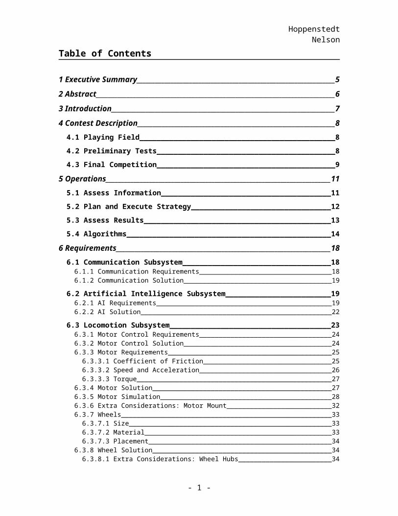
Table of Contents
1 Executive Summary_____________________________________________________5
2 Abstract_______________________________________________________________6
3 Introduction___________________________________________________________7
4 Contest Description______________________________________________________84.1 Playing Field_____________________________________________________________8
4.2 Preliminary Tests_________________________________________________________8
4.3 Final Competition_________________________________________________________9
5 Operations____________________________________________________________115.1 Assess Information_______________________________________________________11
5.2 Plan and Execute Strategy_________________________________________________12
5.3 Assess Results____________________________________________________________13
5.4 Algorithms______________________________________________________________14
6 Requirements_________________________________________________________186.1 Communication Subsystem________________________________________________18
6.1.1 Communication Requirements___________________________________________________186.1.2 Communication Solution_______________________________________________________19
6.2 Artificial Intelligence Subsystem____________________________________________196.2.1 AI Requirements______________________________________________________________196.2.2 AI Solution__________________________________________________________________22
6.3 Locomotion Subsystem____________________________________________________236.3.1 Motor Control Requirements____________________________________________________246.3.2 Motor Control Solution_________________________________________________________246.3.3 Motor Requirements___________________________________________________________25
6.3.3.1 Coefficient of Friction______________________________________________________256.3.3.2 Speed and Acceleration_____________________________________________________266.3.3.3 Torque__________________________________________________________________27
6.3.4 Motor Solution_______________________________________________________________276.3.5 Motor Simulation_____________________________________________________________286.3.6 Extra Considerations: Motor Mount_______________________________________________326.3.7 Wheels______________________________________________________________________33
6.3.7.1 Size____________________________________________________________________336.3.7.2 Material_________________________________________________________________336.3.7.3 Placement_______________________________________________________________34
6.3.8 Wheel Solution_______________________________________________________________346.3.8.1 Extra Considerations: Wheel Hubs____________________________________________34
6.4 Chassis_________________________________________________________________356.4.1 Chassis Requirement___________________________________________________________356.4.2 Chassis Solution______________________________________________________________35
6.4.2.1 Bottom Tier______________________________________________________________356.4.2.2 Middle Tier______________________________________________________________366.4.2.3 Upper Tier_______________________________________________________________37
- 1 -
HoppenstedtNelson
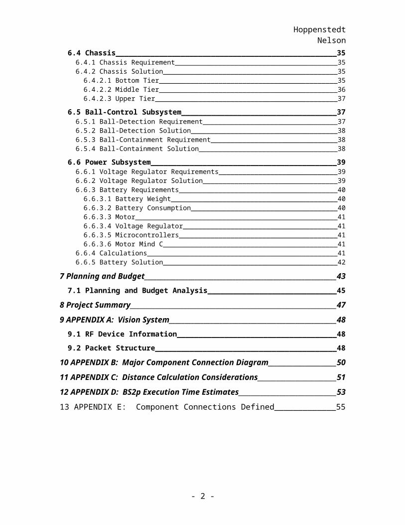
6.5 Ball-Control Subsystem___________________________________________________376.5.1 Ball-Detection Requirement_____________________________________________________376.5.2 Ball-Detection Solution________________________________________________________386.5.3 Ball-Containment Requirement__________________________________________________386.5.4 Ball-Containment Solution______________________________________________________38
6.6 Power Subsystem_________________________________________________________396.6.1 Voltage Regulator Requirements_________________________________________________396.6.2 Voltage Regulator Solution______________________________________________________396.6.3 Battery Requirements__________________________________________________________40
6.6.3.1 Battery Weight___________________________________________________________406.6.3.2 Battery Consumption______________________________________________________406.6.3.3 Motor___________________________________________________________________416.6.3.4 Voltage Regulator_________________________________________________________416.6.3.5 Microcontrollers__________________________________________________________416.6.3.6 Motor Mind C____________________________________________________________41
6.6.4 Calculations__________________________________________________________________416.6.5 Battery Solution______________________________________________________________42
7 Planning and Budget___________________________________________________437.1 Planning and Budget Analysis______________________________________________45
8 Project Summary_______________________________________________________47
9 APPENDIX A: Vision System____________________________________________489.1 RF Device Information____________________________________________________48
9.2 Packet Structure_________________________________________________________48
10 APPENDIX B: Major Component Connection Diagram_____________________50
11 APPENDIX C: Distance Calculation Considerations________________________51
12 APPENDIX D: BS2p Execution Time Estimates____________________________53
13 APPENDIX E: Component Connections Defined____________________________55
- 2 -
HoppenstedtNelson
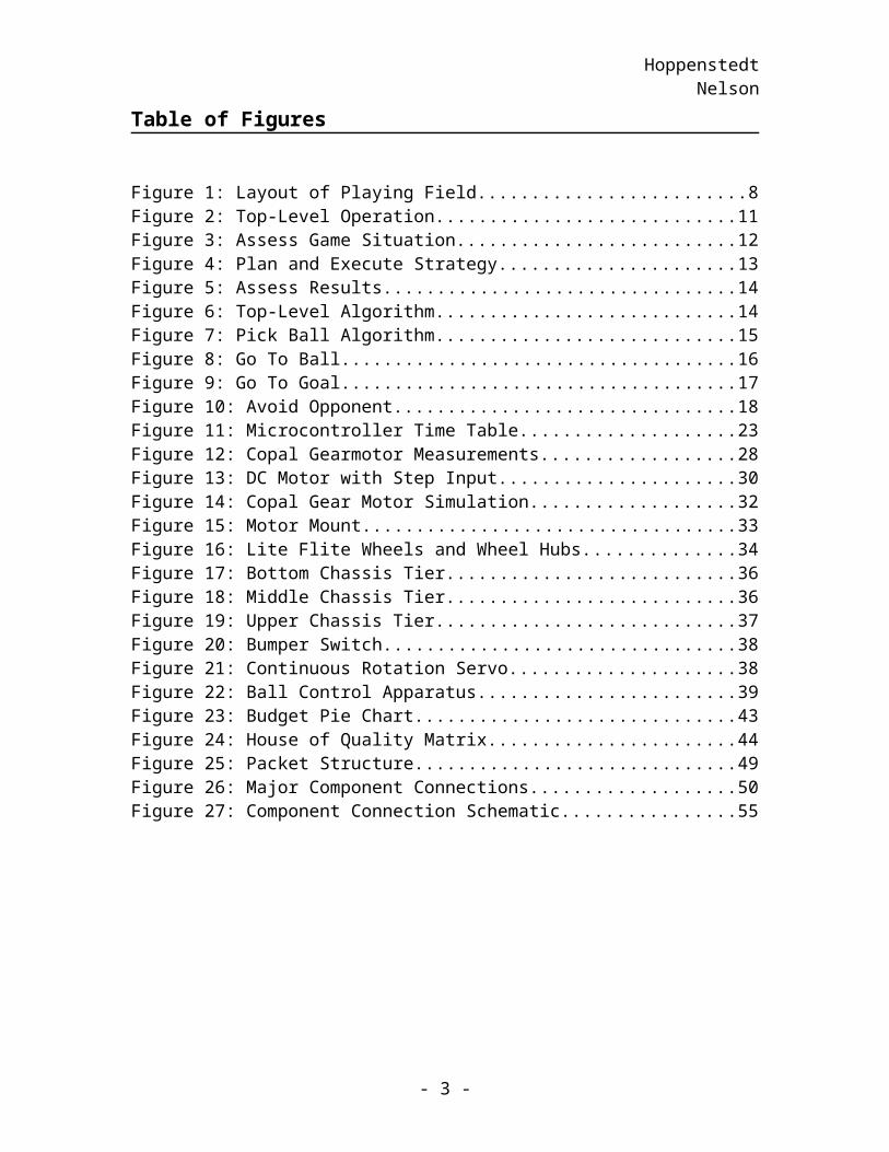
Table of Figures
Figure 1: Layout of Playing Field........................................................................................8Figure 2: Top-Level Operation..........................................................................................11Figure 3: Assess Game Situation.......................................................................................12Figure 4: Plan and Execute Strategy..................................................................................13Figure 5: Assess Results....................................................................................................14Figure 6: Top-Level Algorithm.........................................................................................14Figure 7: Pick Ball Algorithm...........................................................................................15Figure 8: Go To Ball..........................................................................................................16Figure 9: Go To Goal.........................................................................................................17Figure 10: Avoid Opponent...............................................................................................18Figure 11: Microcontroller Time Table.............................................................................23Figure 12: Copal Gearmotor Measurements......................................................................28Figure 13: DC Motor with Step Input................................................................................30Figure 14: Copal Gear Motor Simulation..........................................................................32Figure 15: Motor Mount....................................................................................................33Figure 16: Lite Flite Wheels and Wheel Hubs..................................................................34Figure 17: Bottom Chassis Tier.........................................................................................36Figure 18: Middle Chassis Tier.........................................................................................36Figure 19: Upper Chassis Tier...........................................................................................37Figure 20: Bumper Switch.................................................................................................38Figure 21: Continuous Rotation Servo..............................................................................38Figure 22: Ball Control Apparatus....................................................................................39Figure 23: Budget Pie Chart..............................................................................................43Figure 24: House of Quality Matrix..................................................................................44Figure 25: Packet Structure...............................................................................................49Figure 26: Major Component Connections.......................................................................50Figure 27: Component Connection Schematic..................................................................55
- 3 -
HoppenstedtNelson
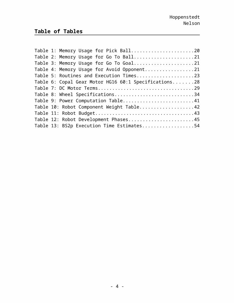
Table of Tables
Table 1: Memory Usage for Pick Ball...............................................................................20Table 2: Memory Usage for Go To Ball............................................................................21Table 3: Memory Usage for Go To Goal...........................................................................21Table 4: Memory Usage for Avoid Opponent...................................................................21Table 5: Routines and Execution Times............................................................................23Table 6: Copal Gear Motor HG16 60:1 Specifications.....................................................28Table 7: DC Motor Terms.................................................................................................29Table 8: Wheel Specifications...........................................................................................34Table 9: Power Computation Table...................................................................................41Table 10: Robot Component Weight Table.......................................................................42Table 11: Robot Budget.....................................................................................................43Table 12: Robot Development Phases...............................................................................45Table 13: BS2p Execution Time Estimates.......................................................................54
- 4 -
HoppenstedtNelson
1 Executive Summary
This document details the design of an autonomous robot that will compete in the Tiger Scramble. This robot must be capable of performing several tasks in order to succeed in the tournament. The main subsystems that will perform these operations are as follows: communication, artificial intelligence, locomotion, ball control, and power.
The communication subsystem receives information from the vision system and sends data to the artificial intelligence subsystem. The artificial intelligence subsystem receives the information from the communication subsystem and performs calculations to tell the locomotion subsystem how to behave. The motor control portion of the locomotion subsystem receives the information from the artificial intelligence subsystem and controls the motors. These subsystems allow the robot to calculate its next actions and travel on the field. The robot is able to transport the ball with the help of the ball control apparatus.
Another subsystem of the robot handles ball control. Once the robot travels to a ball, the robot must be capable of capturing the ball. The robot can then fulfill the task of traveling to the goal and releasing the ball in the appropriate place. The final subsystem discussed in this paper provides power to the components of the robot.
The requirements to achieve the desired performances of these subsystems are described in this paper, and the solutions to meet these specifications are explained. With these five subsystems in place the robot will be competitive in the Tiger Scramble.
- 5 -
HoppenstedtNelson
2 Abstract
The main goal of this robot design is to win in the Tiger Scramble competition. The robots participating in this competition will be autonomous gripping and kicking robots.
As a result of a limited budget, two separate design solutions exist when aiming for a successful outcome in this project. One option is to design a powerful drive train, and invest a large portion of the allotted funds into this subsystem. Teams that choose to optimize the drive train aim to win with superior speed capabilities. The other option is to invest more funds into the artificial intelligence subsystem, which will improve strategy implementation and simplicity.
The robot presented in this paper relies mostly on its components chosen for the artificial intelligence subsystem. Microcontroller capacity and simple implementation are more important than speed for this robot; therefore, most funds for this robot will be invested in the artificial intelligence subsystem. By choosing the simple design route, the time available to test and perfect the game strategy will be maximized.
More time will be available to test and improve the performance of the robot for several reasons. First of all, the team is familiar with the chosen microcontroller. The learning curve is not high when this microcontroller is used. Also, serial interfacing, which is necessary for the chosen strategy implementation, is made simpler with the microcontrollers used. For these reasons, the robot will be on the field earlier, and the system testing and improvement phase will begin sooner.
With this extra time allotted for making modifications on the robot, this team will be better able to win the competition.
- 6 -
HoppenstedtNelson
3 Introduction
The goal of this project is to develop a robot that will compete against an opponent robot in the Tiger Scramble contest. The Systems Engineering Process is the foundation of this study. This process will examine concerns such as cost, risk, and time constraints that are applicable to the design. One determining factor that addresses these concerns is the set of game rules and regulations that must be followed. Essential robot operations and requirements are ultimately defined by the nature of the game. Once the basic operations to be performed by the robot are established, requirements can be more adequately defined. This paper documents the preliminary phase of the robot design project beginning with game rules, operations, and requirements and ending with a budget and planning overview. The section detailing the robot requirements is divided into the following five subsystems: communication, artificial intelligence, locomotion, ball control, and power. The requirement section also considers the chassis design. Through simulation and requirement consideration, a preliminary robot design has been developed and will now be described.
- 7 -
HoppenstedtNelson
4 Contest Description
In order to establish the requirements of the robot design, an analysis of the contest description was performed. The competition analysis is useful in determining the requirements and necessary operations of the robot. Before presenting the rules and regulations of the competition, a description of the playing field is in order.
4.1 Playing Field
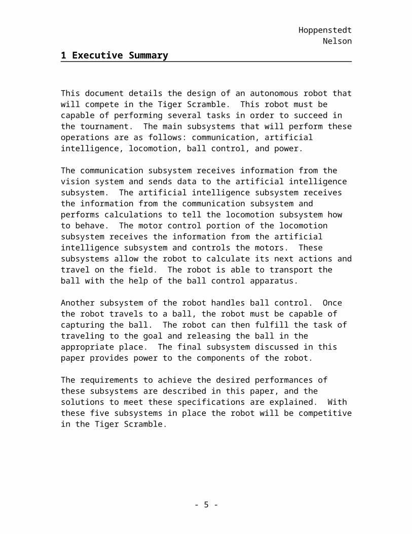
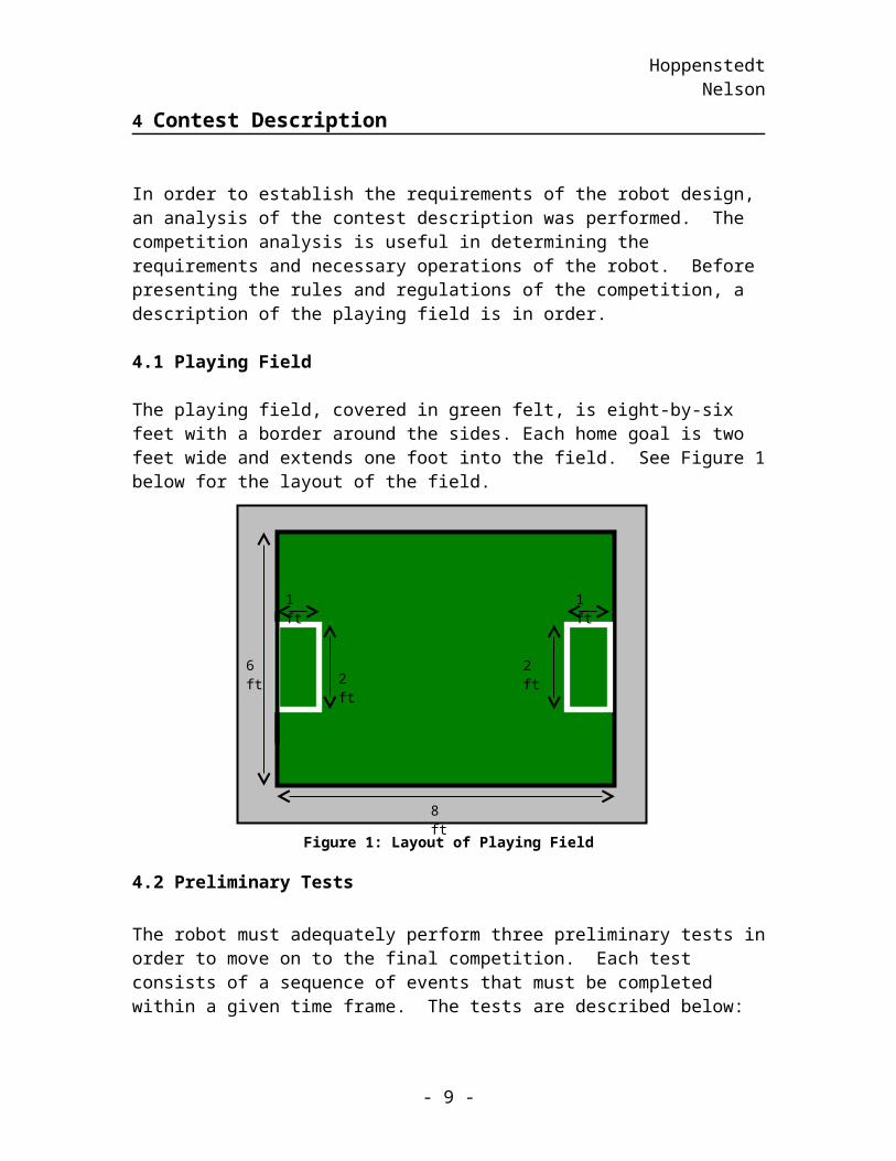
The playing field, covered in green felt, is eight-by-six feet with a border around the sides. Each home goal is two feet wide and extends one foot into the field. See Figure 1 below for the layout of the field.
Figure 1: Layout of Playing Field
4.2 Preliminary Tests
The robot must adequately perform three preliminary tests in order to move on to the final competition. Each test consists of a sequence of events that must be completed within a given time frame. The tests are described below:
Movement test: (Time: 2 minutes)1. Start in home goal.2. Move from the home goal to the opponent’s goal. 3. Go back to the home goal.
Ball-handling test: (Time: 5 minutes)1. Start in home goal.2. Retrieve a single ball from the middle of the field.3. Return to the home goal with the ball.
Multi-ball test: (Time: 15 minutes)
- 8 -
8 ft
6 ft
1 ft 1 ft
2 ft2 ft
HoppenstedtNelson
1. Start in home goal.2. Travel to the center of the field where three balls have been placed. 3. Bring a ball back to the home goal.4. Repeat steps 2 and 3 until all balls are in the goal.
Note: During this routine, an immobile opponent will be located in the path between the home goal and the balls that have been positioned in the middle of the field. Obstacle avoidance techniques must be evident in order to succeed in this event.
Once the robot has successfully met the requirements of these three tests, the robot will advance to the final competition.
4.3 Final Competition
The final competition, called Tiger Scramble, involves two robots that will race to gather tennis balls, which have been placed in the center of the playing field. At the start of each round, five tennis balls will be placed in the center of the field and each robot will be placed in its home goal. At a signal from the referee, the round will start and the robots will begin to gather balls. The first robot with three balls coexisting in its home goal wins the round. A robot must win two out of three rounds to be declared winner.
Each round has a fifteen-minute limit, with a fifteen-minute break between rounds. Furthermore, each robot will be allowed up to two five-minute timeouts per round. In the occurrence that neither robot has three tennis balls coexisting in its home goal within the fifteen-minute time limit, the robot with the most balls in its goal wins the round. If both robots have the same number of balls in their goals at the end of a round or neither robot moves for two consecutive minutes, a draw is declared, and the robots must perform a tiebreaker. A tiebreaker consists of the robots vying for a single ball placed in the center of the field. The first robot to get the ball into its home goal will win the round. During the struggle for victory, the robots will be subject to various restraints to ensure fairness:
The robots may only have reasonable contact with each other, and excessive contact intending to cause damage will result in a warning and ultimately disqualification for the round.
The robots must not damage the playing arena. The top of the robot must be flat black. Each robot must fit in a 12-inch cube. The robot is allowed three potential methods of ball control. Under the condition
that it only has control over one ball at a time, the robot is permitted to capture, push, or kick.
Stealing a ball from the opponent’s goal is allowed. The robot must be designed to accomplish these tasks with a strict budget of five
hundred dollars.
- 9 -
HoppenstedtNelson
5 Operations
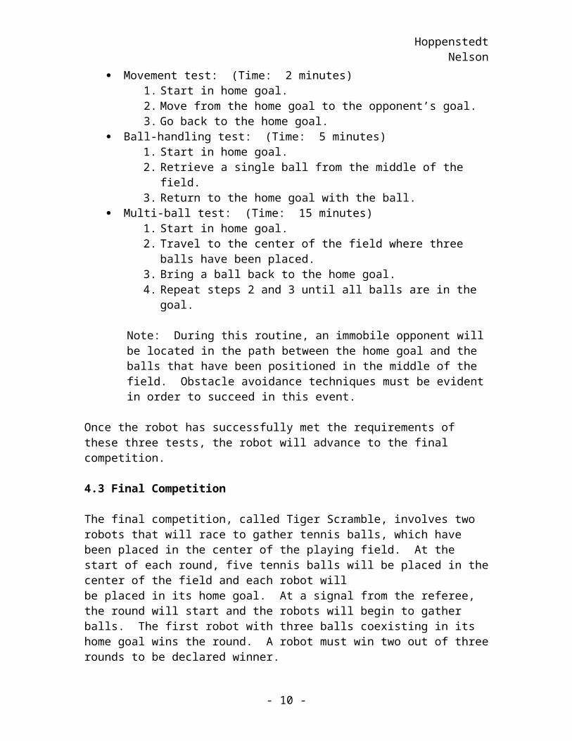
After assessing the nature of the preliminary tests and of the contest, an idea of how the robot must function in order to successfully fulfill the goals involved in the competition was developed. The robot must be able to assess information during the game, execute a game strategy, and assess the results of the operations performed during the execution this strategy. See Figure 2 for the top-level operation functional flow block diagram. The following is a further analysis of necessary functions of the robot and reasoning behind the game strategy decisions.
Figure 2: Top-Level Operation
5.1 Assess Information
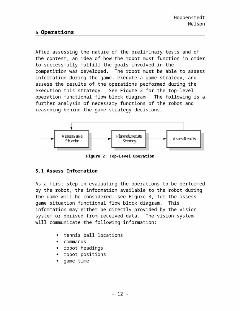
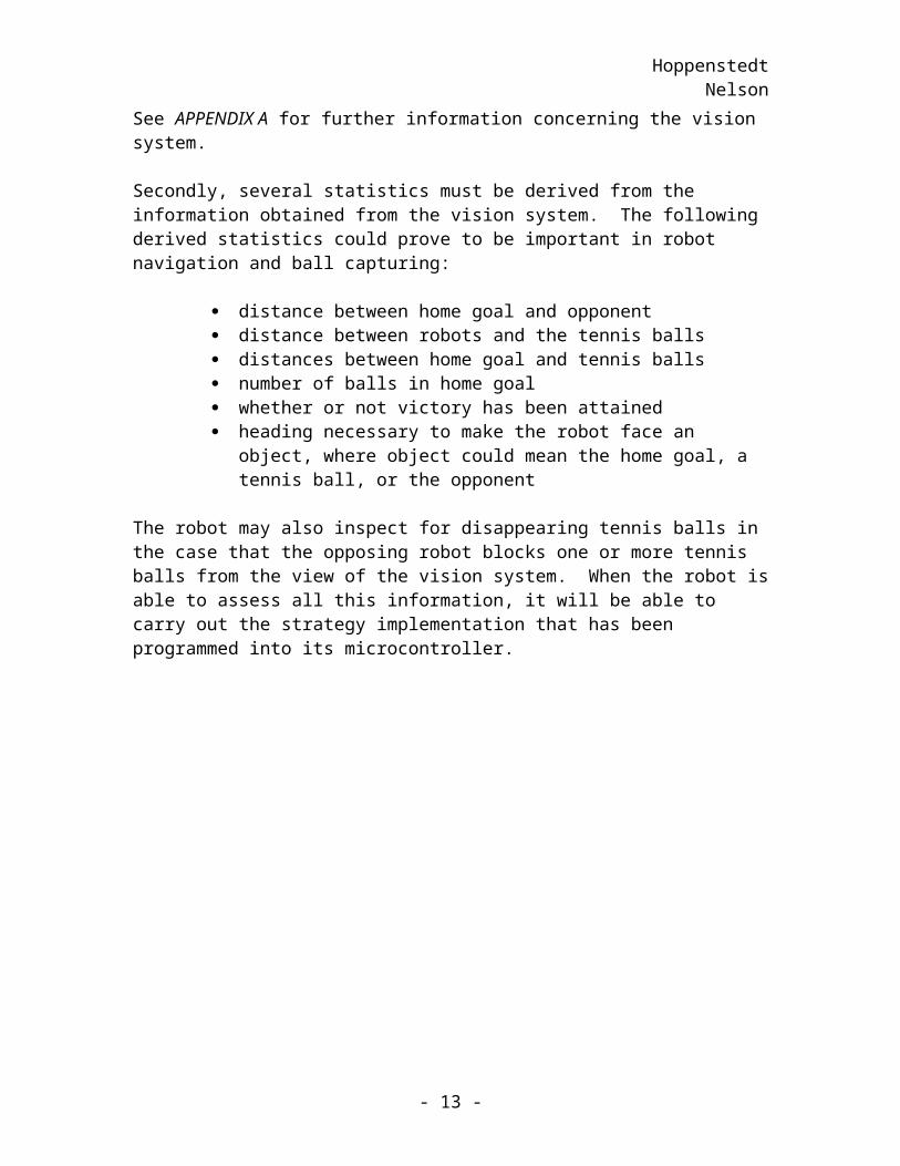
As a first step in evaluating the operations to be performed by the robot, the information available to the robot during the game will be considered, see Figure 3, for the assess game situation functional flow block diagram. This information may either be directly provided by the vision system or derived from received data. The vision system will communicate the following information:
tennis ball locations commands robot headings robot positions game time
See APPENDIX A for further information concerning the vision system.
Secondly, several statistics must be derived from the information obtained from the vision system. The following derived statistics could prove to be important in robot navigation and ball capturing:
distance between home goal and opponent distance between robots and the tennis balls distances between home goal and tennis balls number of balls in home goal whether or not victory has been attained heading necessary to make the robot face an object, where object could
mean the home goal, a tennis ball, or the opponent
- 10 -
HoppenstedtNelson
The robot may also inspect for disappearing tennis balls in the case that the opposing robot blocks one or more tennis balls from the view of the vision system. When the robot is able to assess all this information, it will be able to carry out the strategy implementation that has been programmed into its microcontroller.
Figure 3: Assess Game Situation
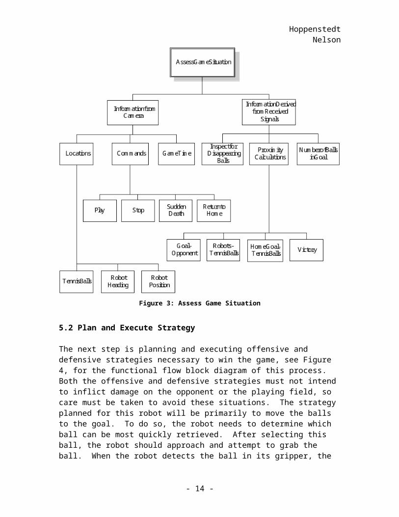
5.2 Plan and Execute Strategy
The next step is planning and executing offensive and defensive strategies necessary to win the game, see Figure 4, for the functional flow block diagram of this process. Both the offensive and defensive strategies must not intend to inflict damage on the opponent or the playing field, so care must be taken to avoid these situations. The strategy planned for this robot will be primarily to move the balls to the goal. To do so, the robot needs to determine which ball can be most quickly retrieved. After selecting this ball, the robot should approach and attempt to grab the ball. When the robot detects the ball in its gripper, the gripper will close to secure the tennis ball. With the tennis ball in its grasp,
- 11 -
HoppenstedtNelson
the robot will make its way towards the goal and finally drop the ball into the goal. The robot will execute the strategy outlined above using the microcontrollers and the mechanisms devised for ball control, locomotion, and object avoidance. See the Algorithms subsection below for a more detailed outline of the strategy.
Figure 4: Plan and Execute Strategy
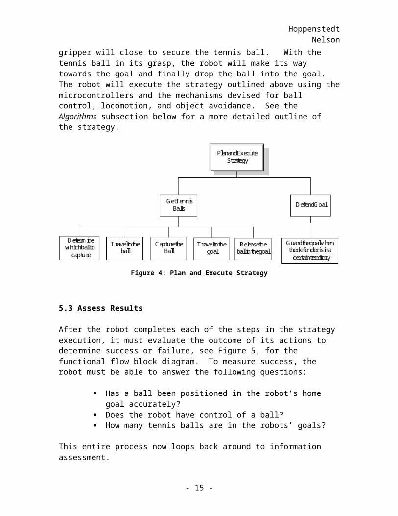
5.3 Assess Results
After the robot completes each of the steps in the strategy execution, it must evaluate the outcome of its actions to determine success or failure, see Figure 5, for the functional flow block diagram. To measure success, the robot must be able to answer the following questions:
Has a ball been positioned in the robot’s home goal accurately? Does the robot have control of a ball? How many tennis balls are in the robots’ goals?
This entire process now loops back around to information assessment.
- 12 -
HoppenstedtNelson
Figure 5: Assess Results
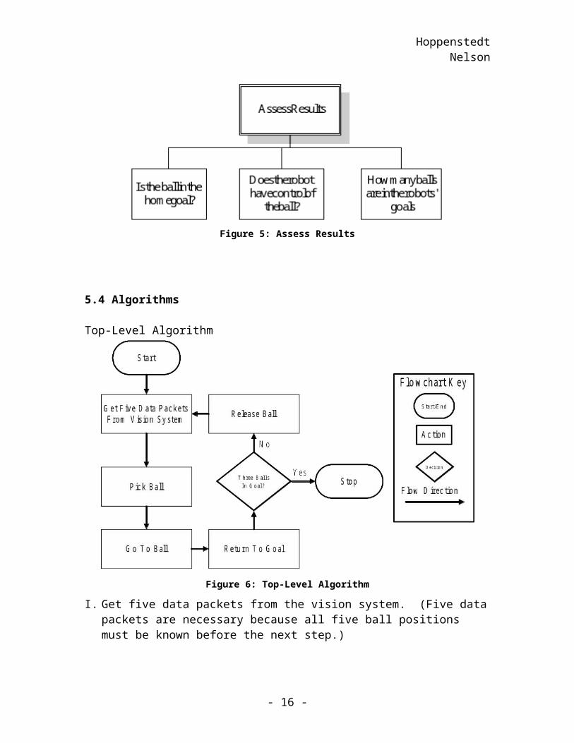
5.4 Algorithms
Top-Level Algorithm
Figure 6: Top-Level Algorithm
I. Get five data packets from the vision system. (Five data packets are necessary because all five ball positions must be known before the next step.)
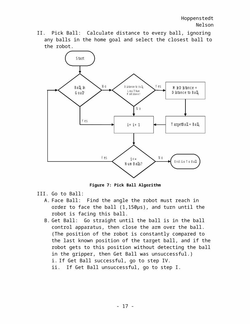
II. Pick Ball: Calculate distance to every ball, ignoring any balls in the home goal and select the closest ball to the robot.
- 13 -
HoppenstedtNelson
Figure 7: Pick Ball Algorithm
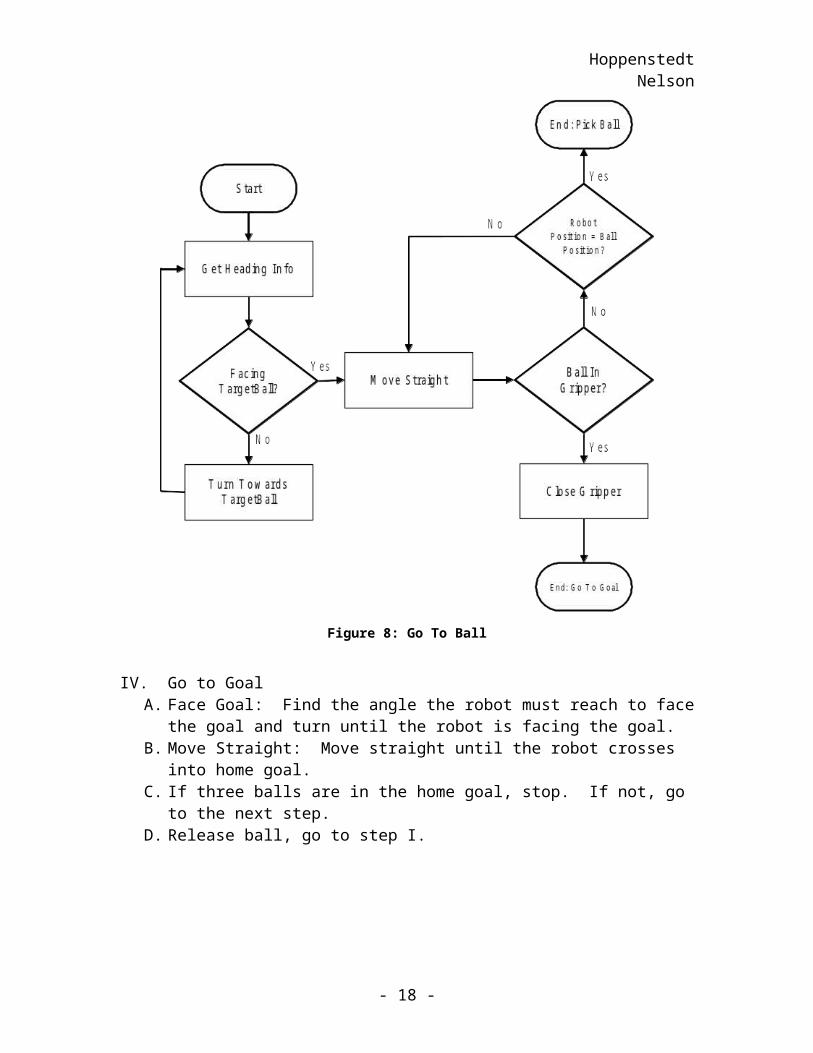
III. Go to Ball:A. Face Ball: Find the angle the robot must reach in order to face the ball (1,150µs),
and turn until the robot is facing this ball.B. Get Ball: Go straight until the ball is in the ball control apparatus, then close the
arm over the ball. (The position of the robot is constantly compared to the last known position of the target ball, and if the robot gets to this position without detecting the ball in the gripper, then Get Ball was unsuccessful.)i. If Get Ball successful, go to step IV.ii. If Get Ball unsuccessful, go to step I.
- 14 -
HoppenstedtNelson
Figure 8: Go To Ball
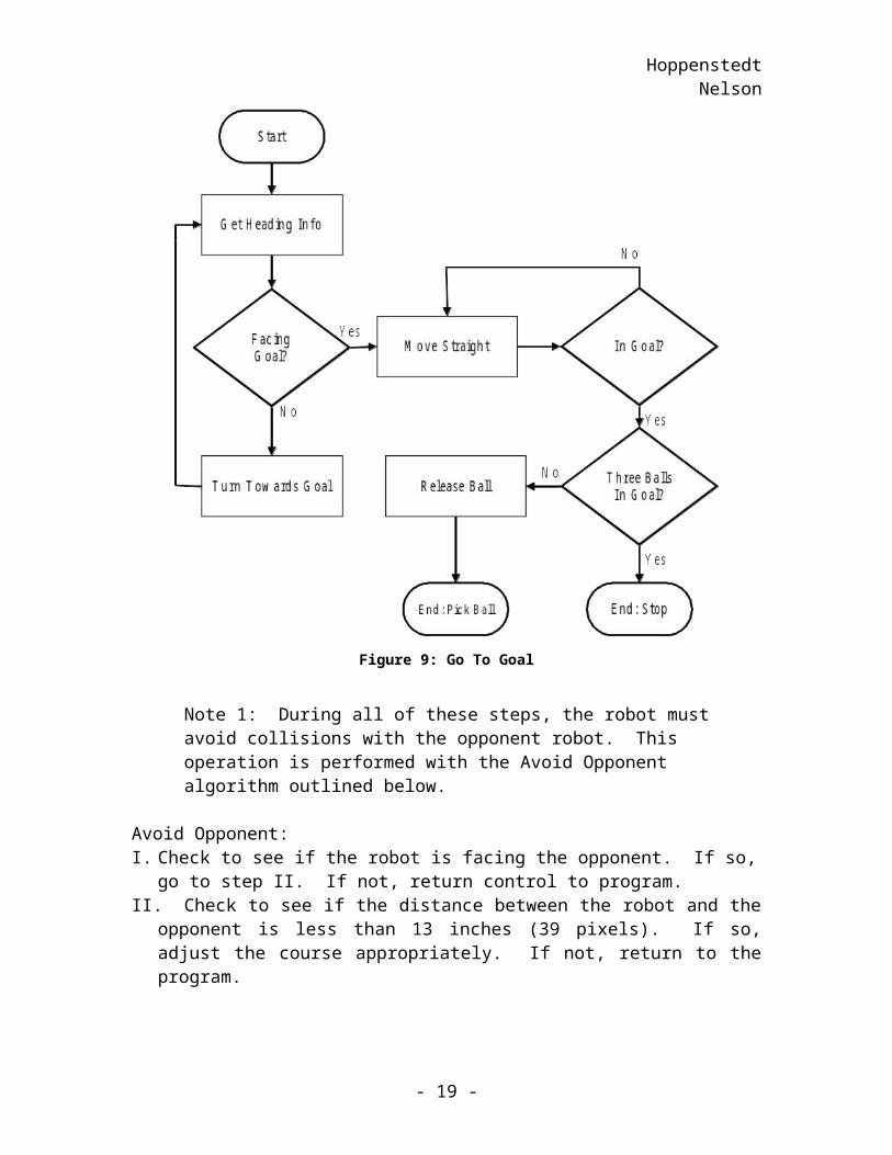
IV. Go to GoalA. Face Goal: Find the angle the robot must reach to face the goal and turn until the
robot is facing the goal.B. Move Straight: Move straight until the robot crosses into home goal.C. If three balls are in the home goal, stop. If not, go to the next step.D. Release ball, go to step I.
- 15 -
HoppenstedtNelson
Figure 9: Go To Goal
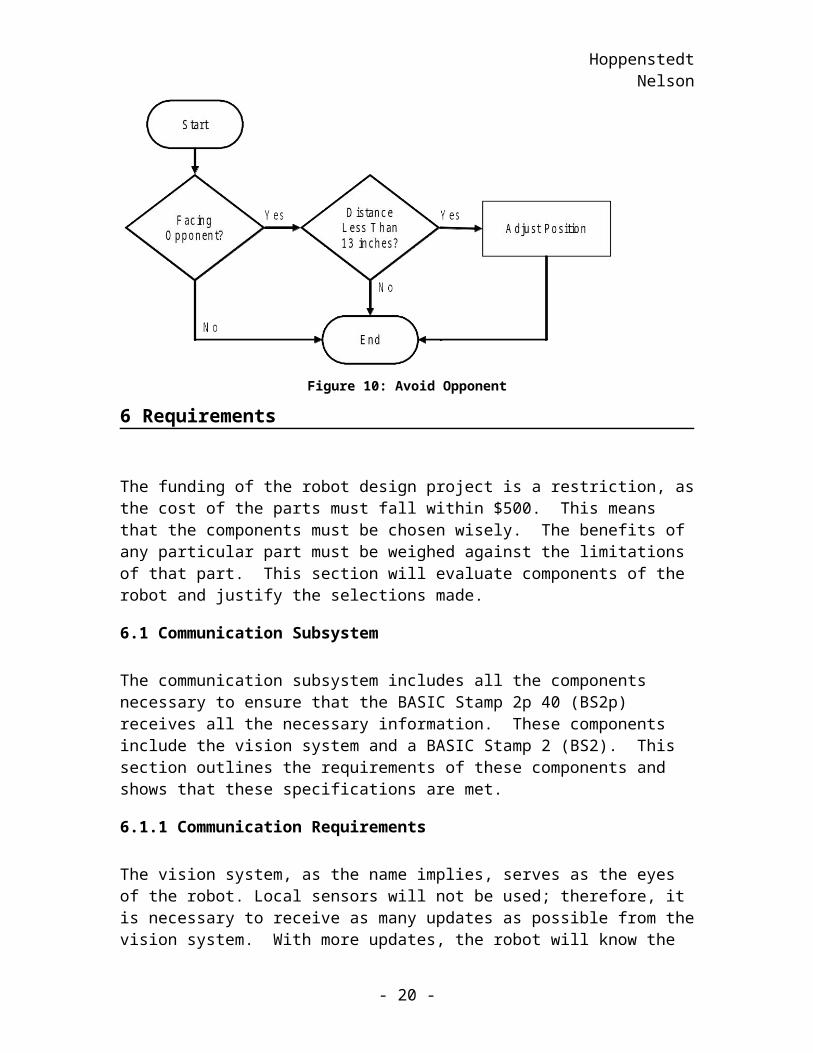
Note 1: During all of these steps, the robot must avoid collisions with the opponent robot. This operation is performed with the Avoid Opponent algorithm outlined below.
Avoid Opponent:I. Check to see if the robot is facing the opponent. If so, go to step II. If not, return
control to program.II. Check to see if the distance between the robot and the opponent is less than 13 inches
(39 pixels). If so, adjust the course appropriately. If not, return to the program.
- 16 -
HoppenstedtNelson
Figure 10: Avoid Opponent
6 Requirements
The funding of the robot design project is a restriction, as the cost of the parts must fall within $500. This means that the components must be chosen wisely. The benefits of any particular part must be weighed against the limitations of that part. This section will evaluate components of the robot and justify the selections made.
6.1 Communication Subsystem
The communication subsystem includes all the components necessary to ensure that the BASIC Stamp 2p 40 (BS2p) receives all the necessary information. These components include the vision system and a BASIC Stamp 2 (BS2). This section outlines the requirements of these components and shows that these specifications are met.
6.1.1 Communication Requirements
The vision system, as the name implies, serves as the eyes of the robot. Local sensors will not be used; therefore, it is necessary to receive as many updates as possible from the vision system. With more updates, the robot will know the locations of objects on the field more accurately at any point in time. The vision system, as described in APPENDIX A, requires 33 ms to send each packet of information. One consideration addresses the fact that the BS2p cannot perform any other task while receiving data. If 10 packets are received every second, and each packet takes 33 ms to be received, then the BS2p will spend one-third of its time tied up in serial communication with the vision system. By spending less time communicating with the vision system, the BS2p will have more time available to perform calculations and direct the other subsystems.
- 17 -
HoppenstedtNelson
6.1.2 Communication Solution
To alleviate the problem of communication engagement with the vision system for one-third of the time, a BS2 was added to the design. This additional component solves this dilemma by receiving information from the vision system and sending this information to the BS2p. A considerable amount of time will be saved with this design.
Instead of being tied-up for 33 ms to receive a packet, the BS2p, with the BS2 receiving the data from the vision system, will spend approximately 3.75 ms per packet engaged in receiving updates from the vision system. This approximation is derived from the assumption that the maximum baud rate of flow controlled serial transfer for the BS2 (19.2k) and ignores the setup time for the BS2 to start sending data. This gives the BS2p approximately 96 ms to carry out other tasks between updates from the vision system.
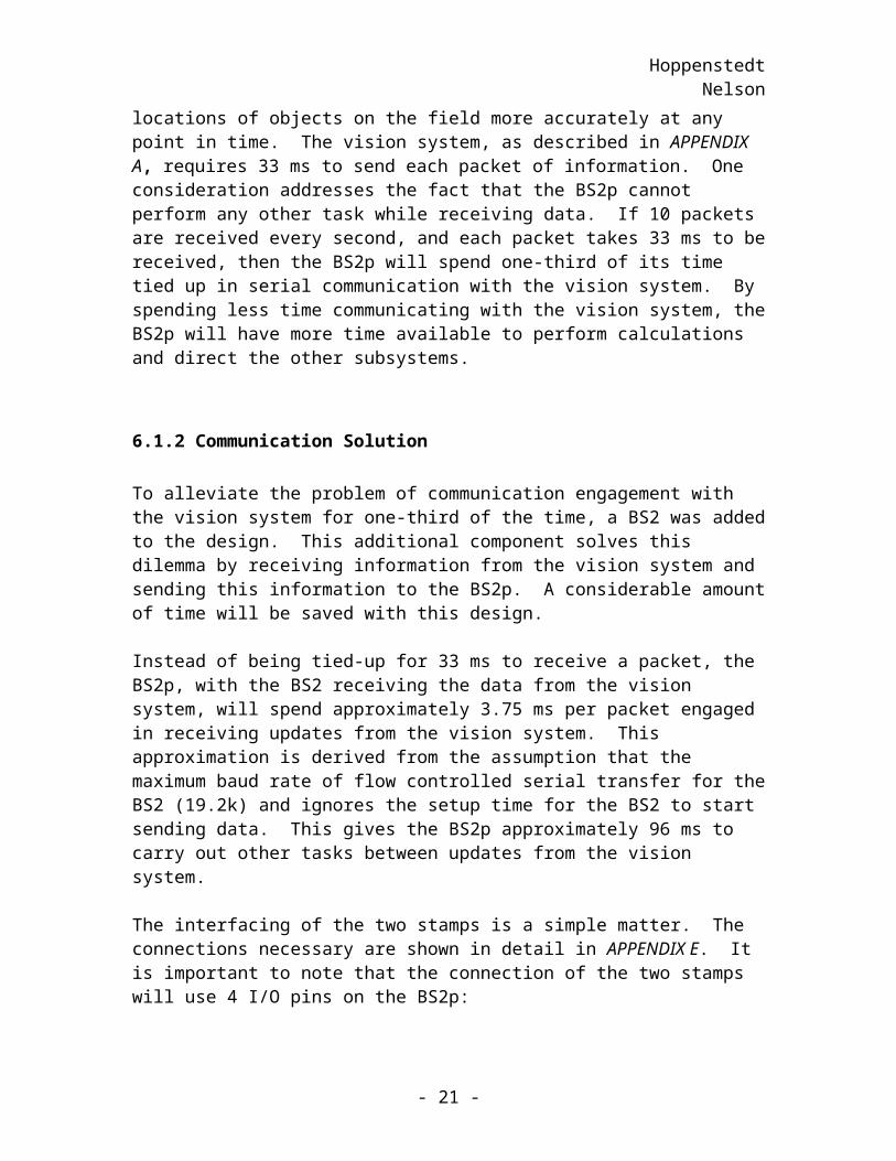
The interfacing of the two stamps is a simple matter. The connections necessary are shown in detail in APPENDIX E. It is important to note that the connection of the two stamps will use 4 I/O pins on the BS2p:
One pin for serial data transfer One pin for flow control Two pins for handshaking
The purpose of the serial data transfer connection is obvious. The pin for flow control is used so that the BASIC Stamps will take all the necessary steps to set up the communication without considerable difficulty on the part of the programmer. The two handshaking pins are for a simplistic serial protocol. Each stamp will set a pin high whenever it is ready, and the BS2 will only start sending data when both stamps are ready.
6.2 Artificial Intelligence Subsystem
The artificial intelligence subsystem includes all the necessary components for the robot to process information. This section explains why the BS2p is the only component necessary for this subsystem to function properly.
6.2.1 AI Requirements
The requirements addressed in this section include the selected component’s ability to perform necessary calculations, with the execution speeds of these calculations taken as considerations, and the memory requirements of the brain of the robot. The phrase “necessary calculations”, in this context, refers to calculations required for the competition as well as the preliminary tests. This section also addresses the necessary control requirements of the brain of the system. This is simply a check to determine if
- 18 -
HoppenstedtNelson
the brain that was chosen has a sufficient number of I/O pins to interface with all of the subsystems.
This section will not provide an exhaustive list of all the necessary arithmetic functions, but will instead focus on the arithmetic functions that are utilized most frequently or that are the most complicated. The most complicated and widely used function is the calculation of the distance between two points given the coordinates these points. Calculating target angles is a less commonly used, but not necessarily less complicated function that is required to pass the preliminary tests as well as achieve victory. Given the coordinates of two points, such as the position for the robot and a ball, arctangent is used to calculate the target angle necessary so that the robot faces the ball. Other than angle and distance calculations, additions, comparisons, and various other simple arithmetic and logical functions will be necessary. However, these calculations are not described here, as no special considerations must be made in implementing these “simple” functions.
Execution speed is a very important statistic to consider. A stated previously, every packet sent by the vision system will be utilized. In order to do this effectively, the brain of the robot must be able to perform any and all necessary calculations within a certain timeframe. This timeframe can be considered as a 96 ms window between the end time of receiving one packet and the start time of receiving the next packet.
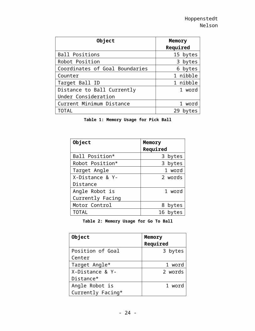
Finally, the brain must have enough memory to store any pertinent data (robot position, ball positions, etc.) and still have ample space for intermediate variables used in calculations. Using tables to outline the amount of memory required for each function is an easy way to show the memory requirement of the system as a whole. These tables are shown below.
Memory Usage Tables:
Note: An asterisk (*) denotes an object that is used in the function, but the memory required was allocated in a previously described function. These objects are not included in calculating the total memory requirement for the function.
Object Memory RequiredBall Positions 15 bytesRobot Position 3 bytesCoordinates of Goal Boundaries 6 bytesCounter 1 nibbleTarget Ball ID 1 nibbleDistance to Ball Currently Under Consideration 1 wordCurrent Minimum Distance 1 wordTOTAL 29 bytes
Table 1: Memory Usage for Pick Ball
- 19 -
HoppenstedtNelson
Object Memory RequiredBall Position* 3 bytesRobot Position* 3 bytesTarget Angle 1 wordX-Distance & Y-Distance 2 wordsAngle Robot is Currently Facing 1 wordMotor Control 8 bytesTOTAL 16 bytes
Table 2: Memory Usage for Go To Ball
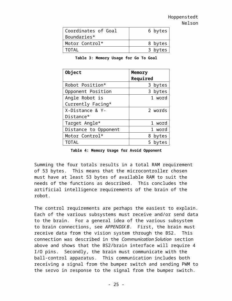
Object Memory RequiredPosition of Goal Center 3 bytesTarget Angle* 1 wordX-Distance & Y-Distance* 2 wordsAngle Robot is Currently Facing* 1 wordCoordinates of Goal Boundaries* 6 bytesMotor Control* 8 bytesTOTAL 3 bytes
Table 3: Memory Usage for Go To Goal
Object Memory RequiredRobot Position* 3 bytesOpponent Position 3 bytesAngle Robot is Currently Facing* 1 wordX-Distance & Y-Distance* 2 wordsTarget Angle* 1 wordDistance to Opponent 1 wordMotor Control* 8 bytesTOTAL 5 bytes
Table 4: Memory Usage for Avoid Opponent
Summing the four totals results in a total RAM requirement of 53 bytes. This means that the microcontroller chosen must have at least 53 bytes of available RAM to suit the needs of the functions as described. This concludes the artificial intelligence requirements of the brain of the robot.
The control requirements are perhaps the easiest to explain. Each of the various subsystems must receive and/or send data to the brain. For a general idea of the various subsystem to brain connections, see APPENDIX B. First, the brain must receive data from the vision system through the BS2. This connection was described in the Communication Solution section above and shows that the BS2/brain interface will
- 20 -
HoppenstedtNelson
require 4 I/O pins. Secondly, the brain must communicate with the ball-control apparatus. This communication includes both receiving a signal from the bumper switch and sending PWM to the servo in response to the signal from the bumper switch. Finally, the brain needs to control the locomotion subsystem to make sure the robot travels to the desired position. This only entails sending serial data to the MMC. The MMC will take care of controlling the motors in order to move the robot. To summarize this requirement, the components listed below require the respective number of I/O pins:
– BS2 (4)– Control servo (1)– Bumper switch (1)– Motor Mind C (2)
While only eight I/O pins are necessary for the control of the various subsystems, another eight will be used for switches to determine the mode of operation of the robot (preliminary test 1,2, or 3, sudden death, etc.). This gives a total requirement of 16 I/O pins on the brain of the robot.
6.2.2 AI Solution
The BS2p module was chosen as the brain of the robot. This microcontroller meets or exceeds all requirements stipulated thus far. Each requirement will be mentioned again, and it will be shown that the brain performs as desired.
In order to set the mode of operation for the robot, switches must be used. This requirement is satisfied by an 8-pin DIP switch.
As mentioned, many distances must be calculated. For this purpose, the BASIC Stamp has a built-in function called HYP. For a full explanation of the HYP command considerations, see APPENDIX C. As for the necessary target angle calculations, the BASIC Stamp has a command, ATN, that will perform these calculations.
The BS2p can perform all necessary calculations, but analysis is needed to determine if these calculations can be carried out fast enough to meet the requirements. As stated, the 96 ms between packets will be used as a guide to determine what execution speed is required. If it can be shown that the BS2p can execute all functions within 96 ms, then the BS2p will be proven fast enough. Execution of all functions will be considered to account for the worst case. All functions will not be executed between every two packets, but if the need arises, the BS2p must be able to accomplish this task.
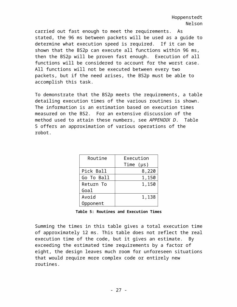
To demonstrate that the BS2p meets the requirements, a table detailing execution times of the various routines is shown. The information is an estimation based on execution times measured on the BS2. For an extensive discussion of the method used to attain these numbers, see APPENDIX D. Table 5 offers an approximation of various operations of the robot.
- 21 -
HoppenstedtNelson
Routine Execution Time (µs)Pick Ball 8,220Go To Ball 1,150Return To Goal 1,150Avoid Opponent 1,138
Table 5: Routines and Execution Times
Summing the times in this table gives a total execution time of approximately 12 ms. This table does not reflect the real execution time of the code, but it gives an estimate. By exceeding the estimated time requirements by a factor of eight, the design leaves much room for unforeseen situations that would require more complex code or entirely new routines.
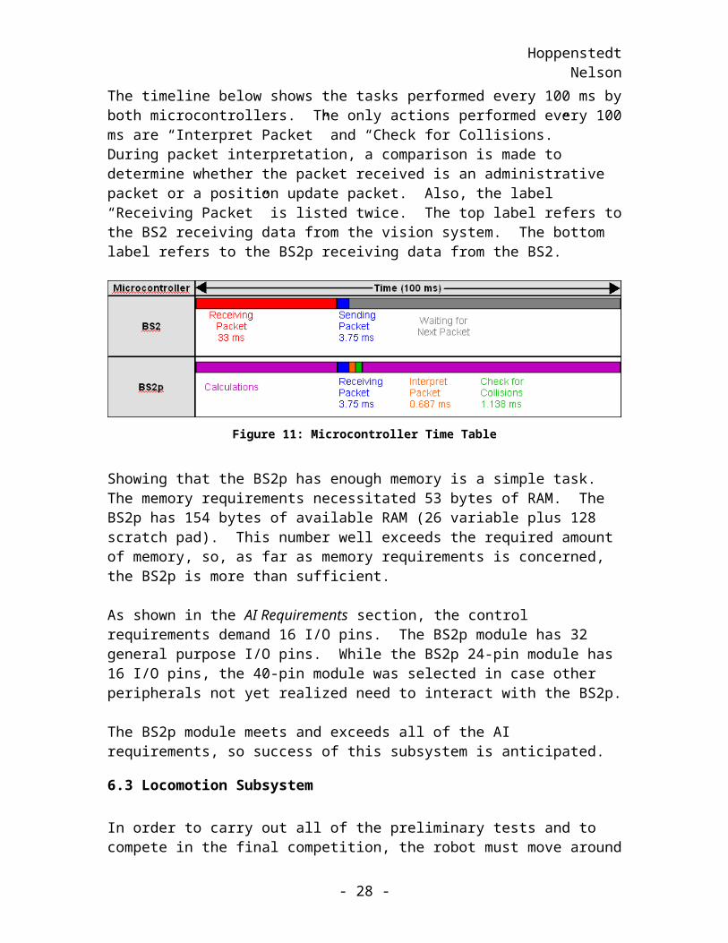
The timeline below shows the tasks performed every 100 ms by both microcontrollers. The only actions performed every 100 ms are “Interpret Packet” and “Check for Collisions.” During packet interpretation, a comparison is made to determine whether the packet received is an administrative packet or a position update packet. Also, the label “Receiving Packet” is listed twice. The top label refers to the BS2 receiving data from the vision system. The bottom label refers to the BS2p receiving data from the BS2.
Figure 11: Microcontroller Time Table
Showing that the BS2p has enough memory is a simple task. The memory requirements necessitated 53 bytes of RAM. The BS2p has 154 bytes of available RAM (26 variable plus 128 scratch pad). This number well exceeds the required amount of memory, so, as far as memory requirements is concerned, the BS2p is more than sufficient.
As shown in the AI Requirements section, the control requirements demand 16 I/O pins. The BS2p module has 32 general purpose I/O pins. While the BS2p 24-pin module has 16 I/O pins, the 40-pin module was selected in case other peripherals not yet realized need to interact with the BS2p.
The BS2p module meets and exceeds all of the AI requirements, so success of this subsystem is anticipated.
- 22 -
HoppenstedtNelson
6.3 Locomotion Subsystem
In order to carry out all of the preliminary tests and to compete in the final competition, the robot must move around the field. Movement requires a large number of parts: Motor Mind C, Copal Gear Motors, Lite Flite wheels, and mounting accessories. This section outlines the requirements of these components and demonstrates that these specifications are met.
6.3.1 Motor Control Requirements
In order to control the motors, it is necessary to be able to control the voltage across the motors and the direction of current flow through the motors. Pulse width modulation (voltage level control) applied to H-bridges (current direction control) is the simplest solution. While the BS2p can perform PWM, it would be completely occupied while doing so. In other words, the robot would have to stop thinking to move and stop moving to think. This was not desirable, so a motor controller will be implemented. In addition to performing PWM, it is important for the motor controller to have H-bridges to control the current direction through the motor. The importance of having H-bridges on the motor controller is simplicity. It is more efficient to use a single chip that provides both PWM and H-bridges, than to use separate chips for each individual task.
An important factor to consider when selecting a suitable motor controller is that the motor controller needs to supply adequate current to the motors without inflicting damage. The maximum amount of current the motors can draw must be compared to the maximum recommended current that the motor controller can provide.
6.3.2 Motor Control Solution
As stated previously, the selected motor controller must be simple to connect and simple to use. The Solutions Cubed Motor Mind C (MMC) was chosen because it meets this requirement. The MMC has another desirable characteristic not listed in the Motor Control Requirements section. The MMC can control two motors simultaneously.
The MMC has three control modes: analog control, serial control, and R/C pulse control. This section will not describe all three of these, as only serial mode will be used in this design. In serial mode, the user has direct control over speed and direction of one or two motors. If controlling two motors, each motor can be controlled independently. This is accomplished by setting various registers on the MMC. These registers determine percentage of maximum speed and the direction of each motor. The user can also set the PWM dead-band and the PWM step limit.
The robot must have the ability to stop on command. The two methods of braking available when running the MMC in serial mode are dynamic and free spinning. Dynamic braking ties both of the motor leads to the motor supply voltage when the PWM signal is within the error band setting. This causes the motor to stop abruptly. In free spinning
- 23 -
HoppenstedtNelson
mode the PWM duty cycle is set to zero when within the dead band, but the energy accumulated in the motor is not shunted to the supply, as is the case with dynamic braking. Therefore, the motor will slow less abruptly in free spinning mode.
In order for the MMC to behave as specified, two factors must be considered when implementing this hardware. These two factors are the prevention of over current faults and over temperature faults. The stall current of one Copal Gear Motor is 1.6 A, which is acceptable for use with the MMC, considering the fact that this hardware has a current rating of 3 A without cooling and 4.5 A with cooling. An over current fault will occur when either of the two H-bridges onboard the MMC detects a current in excess of 8 A. The small motors chosen will prevent over current faults. An over current fault may also be caused by abrupt starting, stopping, and reversing the motor. By implementing code that will ramp the motor speed up or down as needed, the motors will be unable to make any abrupt movements. Therefore, a current fault should not be a problem for this robot. The second factor to consider is an over temperature fault. This type of fault results when the H-bridge IC temperature exceeds approximately 175 degrees Celsius. During preliminary testing, indications of this type of fault will be observed. If over heating is determined to be a problem, a fan will be mounted above the Motor Mind C as an active cooling method.
Code implementation will help protect the Motor Mind C by checking for fault flags indicating occurrence of a fault condition. The BS2p will determine if one of these flags indicates motor control failure. If an error is detected, an attempt will be made by the Motor Mind C to enable the failed H-bridge.
6.3.3 Motor Requirements
Several initial conditions set the parameters to choose a desirable motor. First, a 12-V power supply will be available to the robot's motors. The robot will be small and light, so a motor of small dimensions is necessary. Determination of appropriate motor specifications is based on a multitude of calculations and analysis of performance requirements.
6.3.3.1 Coefficient of Friction
In order to calculate suitable speed and acceleration specifications for the robot, static and kinetic friction coefficients must first be determined. Because the values for speed and acceleration are approximations for desired components, the friction coefficients are not required to be precise. Estimations for these values are based on the friction coefficients evaluated from other materials. For instance, as an upper limit, the static friction coefficient of rubber on cement is approximately 1, and the kinetic friction coefficient of these materials in contact is around 0.8. The properties of the playing field provide lower friction coefficients than those stated above. To set a lower limit for the static friction coefficient, the properties of a piece of smooth, unpolished wood in contact with another piece of smooth, unpolished wood were considered. An assumption was made that the friction coefficients of the rubber tires on the felt playing field is greater than that of the
- 24 -
HoppenstedtNelson
two pieces of wood in contact. The static friction coefficient between the smooth, unpolished pieces of wood is 0.5. The lower bound for the static coefficient of friction was chosen to be 0.7, which is between the upper and lower bounds of 1 and 0.5. For the kinetic friction coefficient, the properties of rubber on asphalt are used for comparison. This constant is 0.5. By inspection, the kinetic friction coefficient must be lower than the static coefficient of friction. Thus, the kinetic friction coefficient was determined to be 0.6, which is greater than the kinetic friction coefficient of rubber on asphalt (0.5) and less than the static coefficient of friction chosen for the robot (0.7).
6.3.3.2 Speed and Acceleration
The next step in choosing the appropriate motor is determining the appropriate speed and acceleration. First the minimum speed will be calculated, and then the maximum speed and acceleration will be determined.
In accordance with the preliminary speed contest, the robot is required to travel 16 feet in a maximum of two minutes. This imposes a minimum speed requirement of eight feet per minute, or 0.04 meters per second, if turning time is disregarded. Because this speed is far too slow to be successful in the Tiger Scramble competition, more desirable motor characteristics will be defined as requirements below.
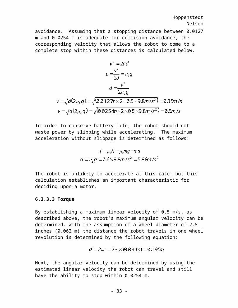
One important consideration in choosing appropriate motor specifications is the matter of obstacle avoidance. In order to avoid a collision with the opponent robot, the robot will be programmed to remain a distance of 13 inches away from the opponent robot. Only a certain degree of slippage will be tolerated in order to ensure obstacle avoidance. Assuming that a stopping distance between 0.0127 m and 0.0254 m is adequate for collision avoidance, the corresponding velocity that allows the robot to come to a complete stop within these distances is calculated below.
In order to conserve battery life, the robot should not waste power by slipping while accelerating. The maximum acceleration without slippage is determined as follows:
- 25 -
HoppenstedtNelson
The robot is unlikely to accelerate at this rate, but this calculation establishes an important characteristic for deciding upon a motor.
6.3.3.3 Torque
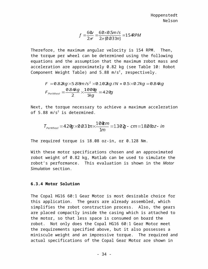
By establishing a maximum linear velocity of 0.5 m/s, as described above, the robot’s maximum angular velocity can be determined. With the assumption of a wheel diameter of 2.5 inches (0.062 m) the distance the robot travels in one wheel revolution is determined by the following equation:
Next, the angular velocity can be determined by using the estimated linear velocity the robot can travel and still have the ability to stop within 0.0254 m.
Therefore, the maximum angular velocity is 154 RPM. Then, the torque per wheel can be determined using the following equations and the assumption that the maximum robot mass and acceleration are approximately 0.82 kg (see Table 10: Robot Component Weight Table) and 5.88 m/s2, respectively.
Next, the torque necessary to achieve a maximum acceleration of 5.88 m/s2 is determined.
The required torque is 18.08 oz-in, or 0.128 Nm.
With these motor specifications chosen and an approximated robot weight of 0.82 kg, Matlab can be used to simulate the robot’s performance. This evaluation is shown in the Motor Simulation section.
6.3.4 Motor Solution
The Copal HG16 60:1 Gear Motor is most desirable choice for this application. The gears are already assembled, which simplifies the robot construction process. Also, the gears are placed compactly inside the casing which is attached to the motor, so that less space is consumed on board the robot. Not only does the Copal HG16 60:1 Gear Motor meet the requirements specified above, but it also possesses a miniscule weight and an
- 26 -
HoppenstedtNelson
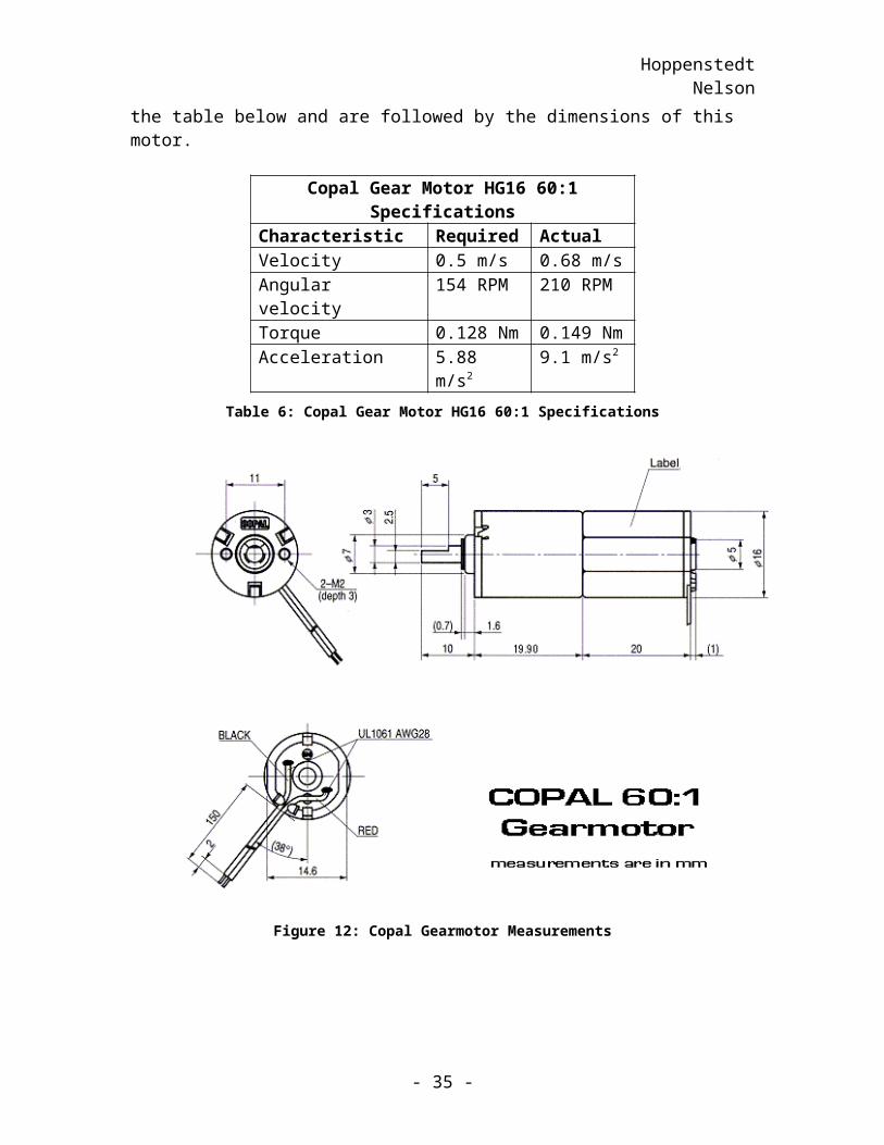
impressive torque. The required and actual specifications of the Copal Gear Motor are shown in the table below and are followed by the dimensions of this motor.
Copal Gear Motor HG16 60:1 SpecificationsCharacteristic Required ActualVelocity 0.5 m/s 0.68 m/sAngular velocity 154 RPM 210 RPMTorque 0.128 Nm 0.149 NmAcceleration 5.88 m/s2 9.1 m/s2
Table 6: Copal Gear Motor HG16 60:1 Specifications
Figure 12: Copal Gearmotor Measurements
6.3.5 Motor Simulation
In order to make an approximation of motor performance, a MATLAB simulation is performed. The first step in this process is to create a model to represent the DC motor, and next find the transfer function. Once the transfer function is derived, the time constant, , can be approximated, which is necessary to solve for the viscous friction, b, of the motor. When these steps are complete, the model can be programmed in
- 27 -
HoppenstedtNelson
MATLAB and simulated with a step response. The following paragraphs detail this process.
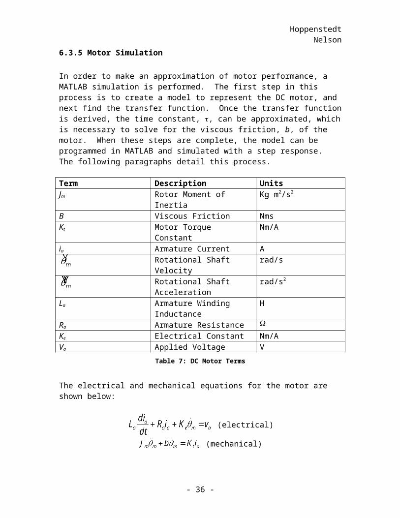
Term Description UnitsJm Rotor Moment of Inertia Kg m2/s2
B Viscous Friction NmsKt Motor Torque Constant Nm/Aia Armature Current A
Rotational Shaft Velocity rad/sRotational Shaft Acceleration rad/s2
La Armature Winding Inductance HRa Armature Resistance Ke Electrical Constant Nm/AVa Applied Voltage V
Table 7: DC Motor Terms
The electrical and mechanical equations for the motor are shown below:
(electrical)
(mechanical)
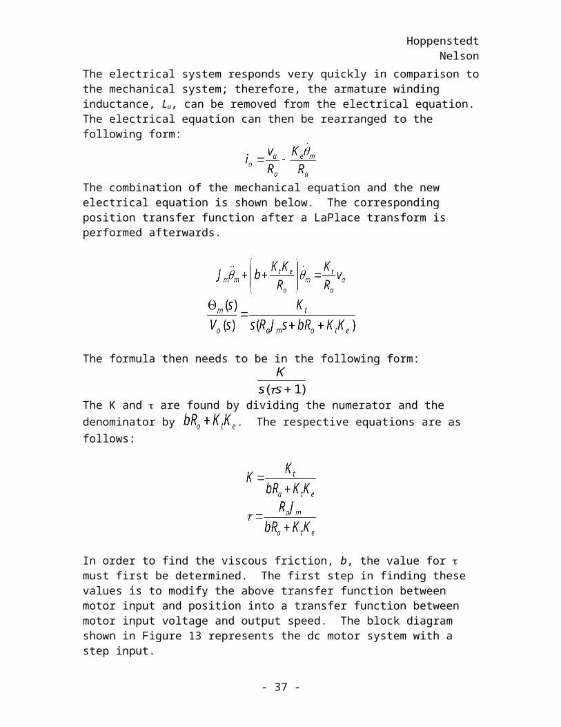
The electrical system responds very quickly in comparison to the mechanical system; therefore, the armature winding inductance, La, can be removed from the electrical equation. The electrical equation can then be rearranged to the following form:
The combination of the mechanical equation and the new electrical equation is shown below. The corresponding position transfer function after a LaPlace transform is performed afterwards.
The formula then needs to be in the following form:
The K and are found by dividing the numerator and the denominator by . The respective equations are as follows:
- 28 -
HoppenstedtNelson
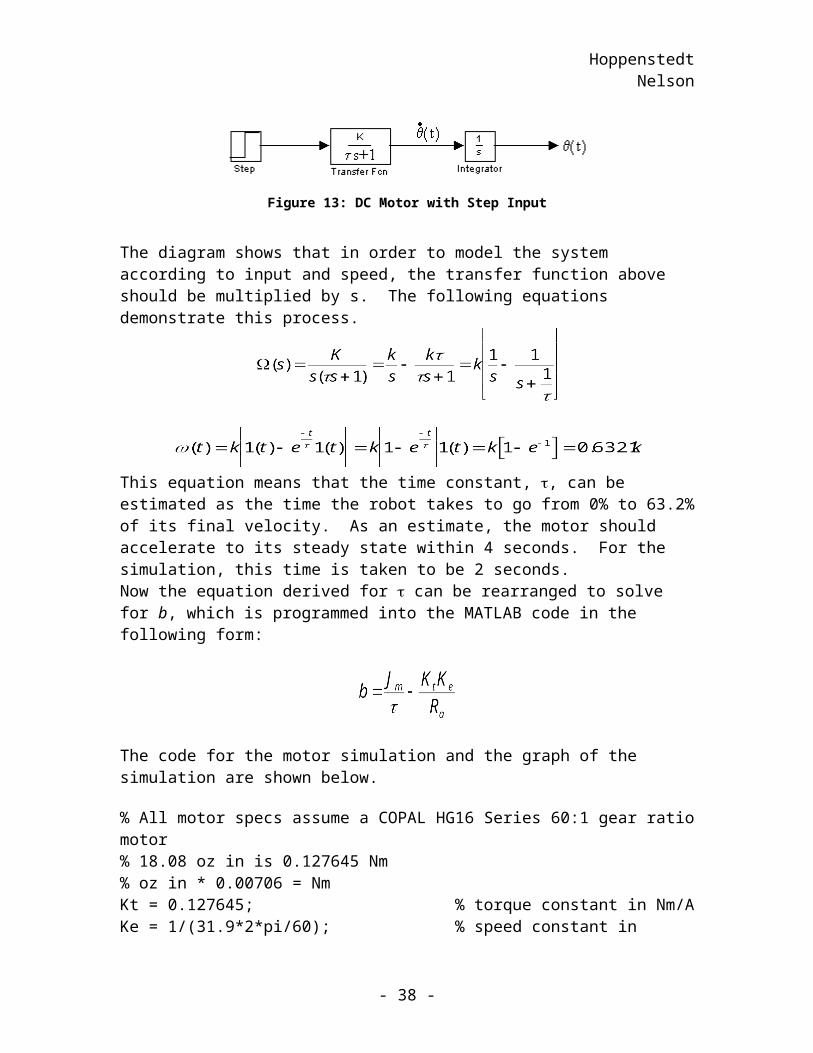
In order to find the viscous friction, b, the value for must first be determined. The first step in finding these values is to modify the above transfer function between motor input and position into a transfer function between motor input voltage and output speed. The block diagram shown in Figure 13 represents the dc motor system with a step input.
Figure 13: DC Motor with Step Input
The diagram shows that in order to model the system according to input and speed, the transfer function above should be multiplied by s. The following equations demonstrate this process.
This equation means that the time constant, , can be estimated as the time the robot takes to go from 0% to 63.2% of its final velocity. As an estimate, the motor should accelerate to its steady state within 4 seconds. For the simulation, this time is taken to be 2 seconds.Now the equation derived for can be rearranged to solve for b, which is programmed into the MATLAB code in the following form:
The code for the motor simulation and the graph of the simulation are shown below.
% All motor specs assume a COPAL HG16 Series 60:1 gear ratio motor% 18.08 oz in is 0.127645 Nm% oz in * 0.00706 = NmKt = 0.127645; % torque constant in Nm/AKe = 1/(31.9*2*pi/60); % speed constant in V/(rad/S)m = 0.82/2; % half of the robot mass (kg)Ra = 1; % armature resistance in ohmsr = 0.062/2; % wheel radius (m)
- 29 -
HoppenstedtNelson
J = 0.5*m*r^2; % wheel rotational inertia in kg m^2ts = 2;t = ts/4.6;b = J/t - Kt*Ke/Ra;num = [Kt];den = [J*Ra b*Ra+Kt*Ke 0];G = tf(num,den)hold on;step(12*G*pi/180,3*pi/180);pause;step(11*G*pi/180,3*pi/180);pause;step(10*G*pi/180,3*pi/180);pause;step(9*G*pi/180,3*pi/180);pause;step(8*G*pi/180,3*pi/180);pause;step(7*G*pi/180,3*pi/180);pause;step(6*G*pi/180,3*pi/180);legend('12V','11','10','9V','8V','7V','6V');hold off;
- 30 -
HoppenstedtNelson
0 0.005 0.01 0.015 0.02 0.025 0.03 0.035 0.04 0.045 0.050
0.02
0.04
0.06
0.08
0.1
0.12
0.14
0.16
0.18
Copal Gear Motor 60:1Input Voltage and Output Speed Characteristic
Time (sec)
Dis
tanc
e (m
)12V11109V8V7V6V
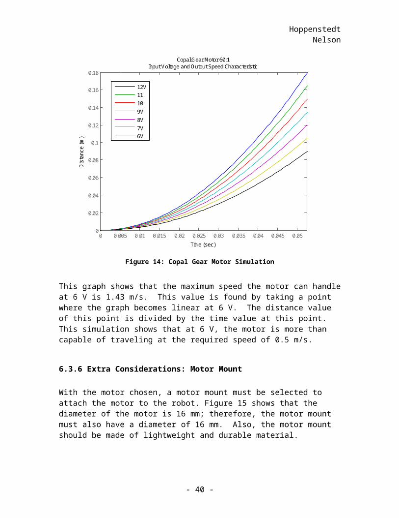
Figure 14: Copal Gear Motor Simulation
This graph shows that the maximum speed the motor can handle at 6 V is 1.43 m/s. This value is found by taking a point where the graph becomes linear at 6 V. The distance value of this point is divided by the time value at this point. This simulation shows that at 6 V, the motor is more than capable of traveling at the required speed of 0.5 m/s.
6.3.6 Extra Considerations: Motor Mount
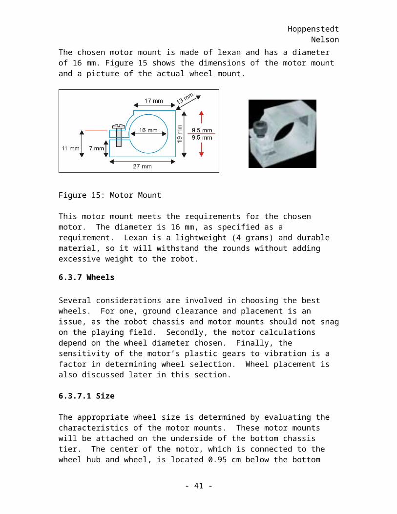
With the motor chosen, a motor mount must be selected to attach the motor to the robot. Figure 15 shows that the diameter of the motor is 16 mm; therefore, the motor mount must also have a diameter of 16 mm. Also, the motor mount should be made of lightweight and durable material.
The chosen motor mount is made of lexan and has a diameter of 16 mm. Figure 15 shows the dimensions of the motor mount and a picture of the actual wheel mount.
- 31 -
HoppenstedtNelson
Figure 15: Motor Mount
This motor mount meets the requirements for the chosen motor. The diameter is 16 mm, as specified as a requirement. Lexan is a lightweight (4 grams) and durable material, so it will withstand the rounds without adding excessive weight to the robot.
6.3.7 Wheels
Several considerations are involved in choosing the best wheels. For one, ground clearance and placement is an issue, as the robot chassis and motor mounts should not snag on the playing field. Secondly, the motor calculations depend on the wheel diameter chosen. Finally, the sensitivity of the motor’s plastic gears to vibration is a factor in determining wheel selection. Wheel placement is also discussed later in this section.
6.3.7.1 Size
The appropriate wheel size is determined by evaluating the characteristics of the motor mounts. These motor mounts will be attached on the underside of the bottom chassis tier. The center of the motor, which is connected to the wheel hub and wheel, is located 0.95 cm below the bottom chassis plate. If the wheel is 6.2 cm in diameter, the clearance between the ground and the bottom of the motor mount, is 2.95 cm. This clearance is sufficient for use on a flat playing field. Also, the wheels will not protrude through the bottom chassis plate so far as to obstruct the components placed on this level. With a chassis plate thickness of 0.6 cm, the outer rim of the wheel will be 2.35 cm above the bottom chassis plate.
6.3.7.2 Material
The wheel material was chosen to provide shock absorption and also to provide traction on the playing field. Because the motors chosen have gears made of plastic, a wheel material must be chosen that will protect the delicate gears from stripping. Rubber is a logical choice for this purpose, but foam wheels absorb shock better than rubber wheels. Also, foam wheels are lighter, so they will not drain battery power unnecessarily.
- 32 -
HoppenstedtNelson
6.3.7.3 Placement
The first issue to discuss in this section is the number of wheels on the robot and the placement of these wheels. Two wheels and one caster will be used for this design because of the superior turning radius of this formation. Furthermore, programming for two wheels is much less time-consuming and demanding than writing code for more wheels that are not necessarily needed.
The wheels will be positioned on each side of the bottom chassis along the center line. The robot’s heaviest components, the batteries and wheels, will be placed above the wheels for support.
6.3.8 Wheel Solution
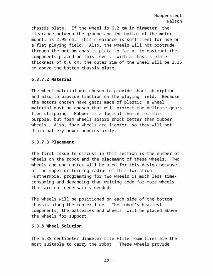
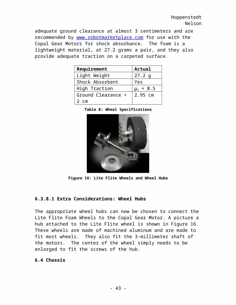
The 6.35 centimeter diameter Lite Flite foam tires are the most suitable to carry the robot. These wheels provide adequate ground clearance at almost 3 centimeters and are recommended by www.robotmarketplace.com for use with the Copal Gear Motors for shock absorbance. The foam is a lightweight material, at 27.2 grams a pair, and they also provide adequate traction on a carpeted surface.
Requirement Actual Light Weight 27.2 gShock Absorbent YesHigh Traction µs = 0.5Ground Clearance > 2 cm 2.95 cm
Table 8: Wheel Specifications
Figure 16: Lite Flite Wheels and Wheel Hubs
6.3.8.1 Extra Considerations: Wheel Hubs The appropriate wheel hubs can now be chosen to connect the Lite Flite Foam Wheels to the Copal Gear Motor. A picture a hub attached to the Lite Flite wheel is shown in Figure16. These wheels are made of machined aluminum and are made to fit most wheels.
- 33 -
HoppenstedtNelson
They also fit the 3-millimeter shaft of the motors. The center of the wheel simply needs to be enlarged to fit the screws of the hub.
6.4 Chassis
The chassis is considered as a subsystem with the three tiers as the components. The requirements of the chassis and proof that these requirements are met are given below.
6.4.1 Chassis Requirement
In order to participate in the competition, the robot must fit within a 12-inch cube. Also, in order for the vision system to accurately detect the position and heading tags on the top of the robot, a flat black top is necessary.
The team has set a convenience requirement that the parts must be easily accessible for testing and various other purposes such as modification. The final requirement determining the chassis design is the placement of the ball control apparatus. The apparatus must be securely mounted on the robot to prevent damage from collisions.
6.4.2 Chassis Solution
A multi-decked circular robot with one flat side best meets the above requirements. By using the triple tiered approach, plenty of room is available to hold the motors, batteries, and rollers for friction reduction on the bottom layer and the BASIC Stamps, the ball control apparatus, the RF receiver, and the sensors on the middle deck. This leaves room on the top tier of the robot, for the position and orientation tags. See APPENDIX C for a major component connection diagram.
After researching the materials available for chassis construction, expanded PVC was decided to be the best choice. This material is lightweight, sturdy, and inexpensive. This material will be ordered in whole sheets and fashioned to meet the specifications drawn for the robot.
6.4.2.1 Bottom Tier
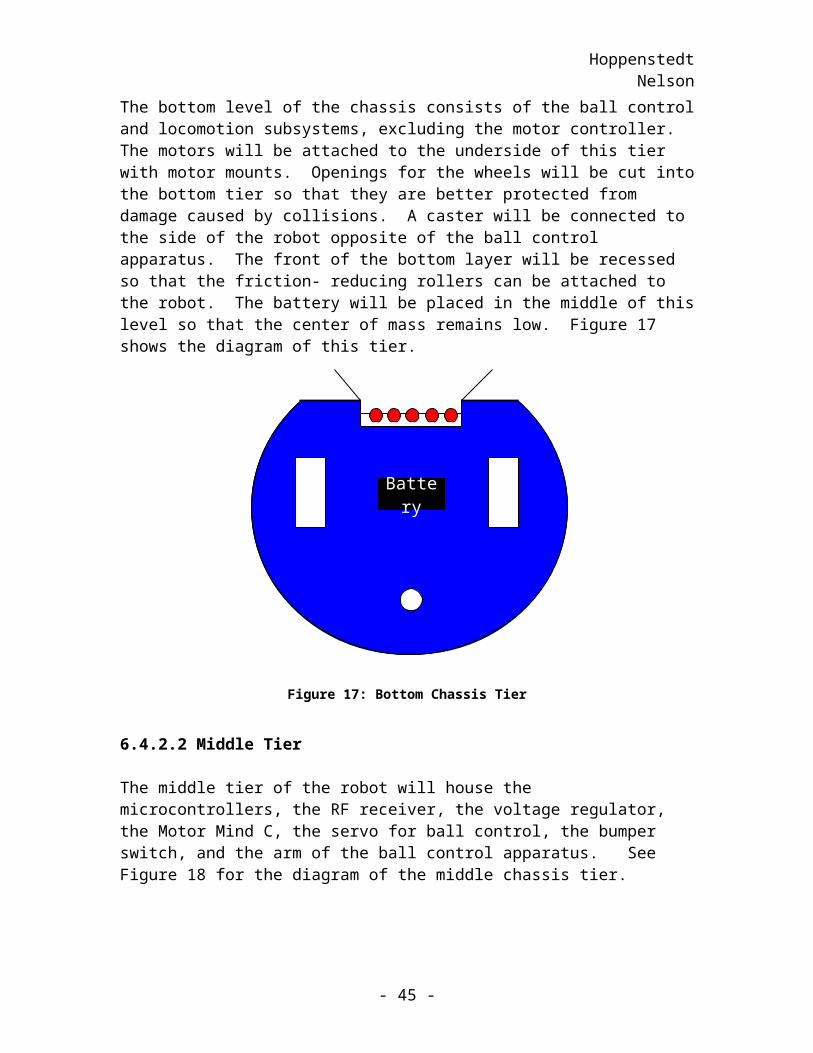
The bottom level of the chassis consists of the ball control and locomotion subsystems, excluding the motor controller. The motors will be attached to the underside of this tier with motor mounts. Openings for the wheels will be cut into the bottom tier so that they are better protected from damage caused by collisions. A caster will be connected to the side of the robot opposite of the ball control apparatus. The front of the bottom layer will be recessed so that the friction- reducing rollers can be attached to the robot. The battery will be placed in the middle of this level so that the center of mass remains low. Figure 17 shows the diagram of this tier.
- 34 -
HoppenstedtNelson
Figure 17: Bottom Chassis Tier
6.4.2.2 Middle Tier
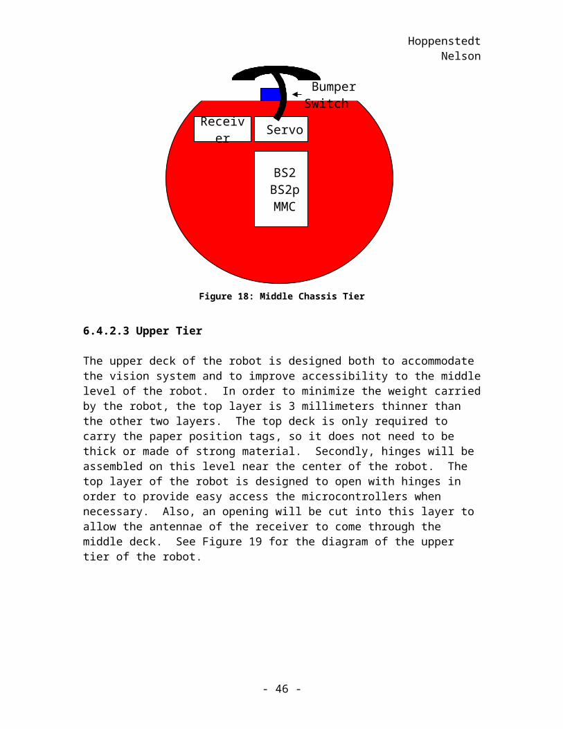
The middle tier of the robot will house the microcontrollers, the RF receiver, the voltage regulator, the Motor Mind C, the servo for ball control, the bumper switch, and the arm of the ball control apparatus. See Figure 18 for the diagram of the middle chassis tier.
Figure 18: Middle Chassis Tier
- 35 -
BatteryBattery
BS2 BS2p MMC
Servo
Bumper Switch
Receiver
HoppenstedtNelson
6.4.2.3 Upper Tier
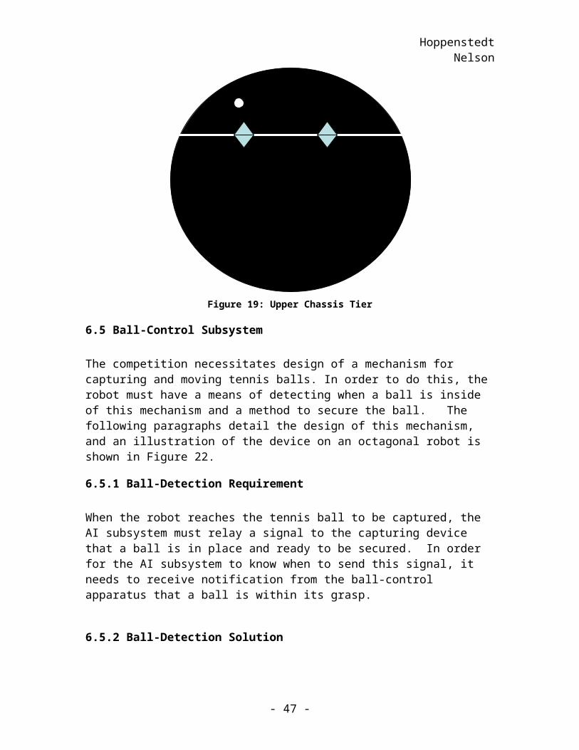
The upper deck of the robot is designed both to accommodate the vision system and to improve accessibility to the middle level of the robot. In order to minimize the weight carried by the robot, the top layer is 3 millimeters thinner than the other two layers. The top deck is only required to carry the paper position tags, so it does not need to be thick or made of strong material. Secondly, hinges will be assembled on this level near the center of the robot. The top layer of the robot is designed to open with hinges in order to provide easy access the microcontrollers when necessary. Also, an opening will be cut into this layer to allow the antennae of the receiver to come through the middle deck. See Figure 19 for the diagram of the upper tier of the robot.
Figure 19: Upper Chassis Tier
6.5 Ball-Control Subsystem
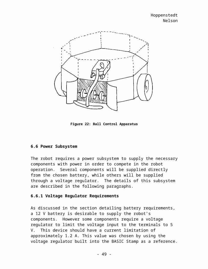
The competition necessitates design of a mechanism for capturing and moving tennis balls. In order to do this, the robot must have a means of detecting when a ball is inside of this mechanism and a method to secure the ball. The following paragraphs detail the design of this mechanism, and an illustration of the device on an octagonal robot is shown in Figure 22.
6.5.1 Ball-Detection Requirement
When the robot reaches the tennis ball to be captured, the AI subsystem must relay a signal to the capturing device that a ball is in place and ready to be secured. In order for the AI subsystem to know when to send this signal, it needs to receive notification from the ball-control apparatus that a ball is within its grasp.
- 36 -
HoppenstedtNelson
6.5.2 Ball-Detection Solution
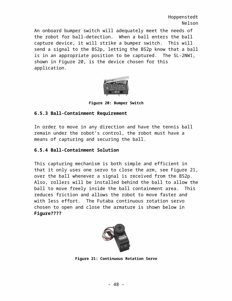
An onboard bumper switch will adequately meet the needs of the robot for ball-detection. When a ball enters the ball capture device, it will strike a bumper switch. This will send a signal to the BS2p, letting the BS2p know that a ball is in an appropriate position to be captured. The SL-2NW1, shown in Figure 20, is the device chosen for this application.
Figure 20: Bumper Switch
6.5.3 Ball-Containment Requirement
In order to move in any direction and have the tennis ball remain under the robot’s control, the robot must have a means of capturing and securing the ball.
6.5.4 Ball-Containment Solution
This capturing mechanism is both simple and efficient in that it only uses one servo to close the arm, see Figure 21, over the ball whenever a signal is received from the BS2p. Also, rollers will be installed behind the ball to allow the ball to move freely inside the ball containment area. This reduces friction and allows the robot to move faster and with less effort. The Futaba continuous rotation servo chosen to open and close the armature is shown below in Figure????
Figure 21: Continuous Rotation Servo
- 37 -
HoppenstedtNelson
Figure 22: Ball Control Apparatus
6.6 Power Subsystem
The robot requires a power subsystem to supply the necessary components with power in order to compete in the robot operation. Several components will be supplied directly from the chosen battery, while others will be supplied through a voltage regulator. The details of this subsystem are described in the following paragraphs.
6.6.1 Voltage Regulator Requirements
As discussed in the section detailing battery requirements, a 12 V battery is desirable to supply the robot’s components. However some components require a voltage regulator to limit the voltage input to the terminals to 5 V. This device should have a current limitation of approximately 1.2 A. This value was chosen by using the voltage regulator built into the BASIC Stamp as a reference.
6.6.2 Voltage Regulator Solution
The microcontrollers, the receiver, the servo, and the bumper switch will be connected to the voltage regulator. The voltage regulators on the BASIC Stamps could provide the required 5 Volts to the necessary components, but the external voltage regulator option
- 38 -
HoppenstedtNelson
was chosen because the I/O pins on the BASIC Stamps can source and sink more current when using an external voltage regulator. The voltage regulator chosen is the LM317T. It can withstand a current of 1.5 A, which meets the requirement of 1.2 A as stated above. This part is a variable voltage regulator, but it can also be set to have a specific output voltage by using a resistor instead of a potentiometer. The calculation for this resistor value, R2, is shown below with R1 given in the datasheet as 240 and a desired output voltage of 5 V.
6.6.3 Battery Requirements
Now that all the battery powered components have been selected, the battery requirements can be established. Several main considerations exist when choosing the appropriate battery. Although the motors chosen for robot locomotion can be connected to 6 V batteries, 12 V batteries are preferable for this application in case additional speed is required. Secondly, the robot must have the capacity to withstand 15-minute rounds in the Tiger Scramble Competition. Another limiting factor is robot weight. In order for the motors to provide adequate speed to the robot, the robot components should be as lightweight as possible. Because the batteries normally comprise a large percentage of the robot’s weight, this aspect must be taken into consideration. Finally, the batteries chosen to supply the robot’s components must be rechargeable. The following section details how the appropriate battery capacity is chosen.
6.6.3.1 Battery Weight
In order to have the option of using smaller and less powerful motors, the robot components chosen should be as light as possible. Batteries tend to contribute to robot weight more than any other part; therefore, a limit should be set on the weight of the batteries. A rough assumption that the weight of the battery should be no more than 20% of the overall weight, shown in Table 10, of the robot imposes a limit of 145 grams allotted to the battery. Therefore, to keep the battery weight in proportion with the remaining robot parts, a battery should be selected with respect to the limit of 145 grams.
6.6.3.2 Battery Consumption
In order to choose an appropriate battery, the robot components that consume battery power must be analyzed. Table 9 displays each component that is powered by the battery, the voltage and current of that component, the percentage of usage time, and the resulting power consumption of each part. The values listed in this table are representative of the worst-case situations.
- 39 -
HoppenstedtNelson
Component Voltage(V) Current(A) % Usage Power (W) 2 Motors 6 3.2 4% (stall) 0.768
6 1.6 96% (normal) 9.216
BS2p40 5 0.1 100% 0.5 BS2-IC 5 0.05 100% 0.25 Motor Mind C 12 0.03 100% 0.36 Servo 5 0.2 100% 1.2 5 V regulator 7 0.357 100% 2.5 Receiver 5 0.007 100% 0.035 Bumper Switch TOTAL 14.6
Table 9: Power Computation Table
6.6.3.3 Motor
The motor is assumed to be in stall mode for approximately 4% of the time. Therefore, the motor is assumed to be in normal mode 96% of the time.
6.6.3.4 Voltage Regulator
With an input of 12 V and an output voltage of 5 V, the power consumed by the voltage regulator is the difference between the input and output voltages multiplied by the sum of the currents of the components powered by the voltage regulator. The following formulas demonstrate these calculations. The currents used in this calculation are those of the BS2p40, the BS2, the servo, and the bumper switch.
6.6.3.5 Microcontrollers
The currents consumed by the microcontrollers as listed in the table assume the worst case conditions. The BS2p40 should not supply more than 100 mA through its general I/O pins, P0-P7. The BS2-IC should not supply more than 50 mA through the general purpose I/O pins while using the external 5 V regulator.
6.6.3.6 Motor Mind C
The MMC is directly supplied by the 12 V battery. The maximum current rating for this device is 3 A or 1.5 A per motor. This maximum current rating is used in the table above.
- 40 -
HoppenstedtNelson
6.6.4 Calculations
The power consumed by each component of the robot is calculated by multiplying the respective voltage by current and the percentage of usage. By summing the power column, the total maximum power consumed by the robot’s components is found to be14.6 W. The estimated battery capacity to supply the robot for 15 minutes is shown in the following calculation to be 0.3 AH.
6.6.5 Battery Solution
The battery chosen is a 12-V 500 mAH NiMh Brick AntPack. This rechargeable battery meets the voltage, longevity, and weight requirements; therefore, the components will function properly through a tournament.
The battery is rated at 12 V, so it meets the requirements to adequately supply the motor and allow for speed control flexibility. Secondly, this battery has a capacity specification of 500 mAH, which means the robot’s computed run time with this battery is 25 minutes. At 98 grams, the battery also meets the weight requirement that it must be less than 145 grams. This battery also meets the final requirement that it must be rechargeable.
Part Quantity WeightBS2 1 9.07 gBS2p40 1 18.14 gMotor Mind C 1 85.28 gMotors 2 54 gWheels 2 27.2 gWheel hubs 2 10 gWheel mounts 2 8 gChassis 1 450 gHinges 2 18 gReceiver 1 45.36 gBattery 1 98 gTotal Weight 823 g
Table 10: Robot Component Weight Table
- 41 -
HoppenstedtNelson
7 Planning and Budget
This section provides information on the robot design strategy, which includes a planning matrix, a preliminary budget proposal, and a time-line. The planning phase is introduced in the form of a House of Quality Chart, shown in Figure 24. In this chart, several factors are weighed against each other and numbers are assigned to these factors’ importance levels. Secondly, the budget table is presented in Table 11 to show that the budget is well below the maximum limit of five hundred dollars. Finally, a time-line of important robot design stages to occur throughout the Fall 2004 semester is provided.
Item Quantity Price per Unit ($)Motors & Mounts 2 30.98Wheels & Hubs 2 7.35Motor Mind C 1 55.00BS2 – IC 1 49.00BS2p 40 1 89.00PCB 1 100.00Chassis 1 9.38Battery 1 29.00Gripper 1 12.69TOTAL 382.40
Table 11: Robot Budget
Robot Budget
Wheels & Hubs
Motor Mind C
BS2 - IC
& MotorsMounts
Chassis
Battery
Gripper
Remaining
BS2p 40PCB
Figure 23: Budget Pie Chart
- 42 -
HoppenstedtNelson
Interrelationship Key■ Strong Relationship● Medium Relationship▲Weak Relationship
Direction of Improvement ↓ ↓ ↑ ↓ ↑ ↓ ↑ ↓ ↑ ↑ ↑ ↓
Technical Requirements
Customer Requirements C
UST
OM
ER IM
POR
TAN
CE
Battery Motor Wheels Electronics Chassis Mech. PlanningMatrix
Num
ber o
f Bat
terie
s
Bat
tery
Siz
e/W
eigh
t (kg
)
Bat
tery
Life
span
Num
ber o
f Mot
ors
Mot
or S
ize/
Wei
ght (
oz)
Mot
or T
orqu
e (o
z-in
)
Num
ber o
f Whe
els
Whe
el S
urfa
ce
Whe
el D
iam
eter
(inc
hes)
Sens
or (B
all C
ontro
l)
Rec
eive
r
Bra
in C
apac
ity
Stan
dard
Bol
ts/S
crew
s
Num
ber o
f Dec
ks
Surf
ace
Are
a Pe
r Dec
k
Grip
per
Ove
rall
Rob
ot W
eigh
t (kg
)
Sale
s Poi
nt
Ove
rall
Wei
ghtin
g
Proc
essi
ng
Detect Surroundings5 ▲ ● ■ 1.5 7.5
Think Quickly4 ● ● 1.2 4.8
Avoid Obstacles4 ● ■ 1.3 5.2
Mot
ion
Travel Smoothly3 ● 1 3
Turn Quickly4 ● ▲ ● 1.2 4.8
Maneuverability4 ■ ■ ■ 1.3 5.2
Ease
of
Part Accessibility3 ▲ ▲ ▲ ▲ ▲ ● ● 1.2 3.6
Easily Adjustable3 ● ● ● 1 3
Few Moving Parts4 ● ● ▲ 1.2 4.8
Stru
ctur
e
Release/Grasp Ball4 ■ ● 1.3 5.2
Lightweight3 ■ ● ▲ ▲ ● 1.3 3.9
Attractive1 1 1
Affordable5 1.5 7.5
Technical Priorities39 4 15 14 65 52 65 54 53 138 9 24 20 34 17
Percentage of Total
Technical Benchmarking 1 .2 2 .9 50 2 ~3 3 1.0
Figure 24: House of Quality Matrix
- 43 -
+
+ -
-
- +
+
--
+- -
HoppenstedtNelson
Task Start Date End Date StatusBrainstorm 8/24 8/26 Complete
Identify project 8/24 8/24Create document of ideas 8/24 8/25Narrow the list of ideas 8/26 8/26
Conceptual Development 8/26 10/18 CompleteDevelop a plan 8/26 8/26Specify operations 8/26 8/27Choose parts for operations 8/27 9/10Cost evaluation 9/10 9/11Risk Analysis 9/11 9/17Create Conceptual Document 8/26 10/18
Preliminary Development 10/18 12/6 CompleteGather information on building materials 10/18 11/1Internal and external review 10/25 11/12Update financial status 11/12 11/12Test microcontrollers 11/13 11/15Create Preliminary Document 10/18 12/6
Robot Construction 12/6 1/18 In ProgressPurchase Parts - -Assemble robot 12/12 12/25Complete initial programming phase 12/12 12/25Testing phase 12/25 1/12Complete programming 1/12 1/18
Table 12: Robot Development Phases
7.1 Planning and Budget Analysis
The House of Quality shows that the robot actions that operate as functions of the microcontrollers are the most important. Therefore the use of the BS2 and the BS2p is justified as the most expensive components in the budget. The matrix shows that the requirements associated with speed are not as critical as the microcontroller requirements; therefore, sacrificing microcontroller capabilities for more costly speed implementation would be unjustified.
The House of Quality also shows that weight is a major factor in choosing parts for the robot. Increasing the weight of the wheels, the motors, the chassis, or the ball control apparatus would result in increasing the weight of the batteries. With heavier batteries, the motors would have higher requirements, and the components would also become more expensive. In order to minimize the funds spent on these components, the weight is kept to a minimum.
The budget chart, shown in Figure 23, shows that by following the requirement rankings listed on the House of Quality matrix, the funds necessitated by the robot are kept within
- 44 -
HoppenstedtNelson
the limit. Twenty percent of the budget remains for any additional parts that may improve the performance of the robot or to provide for any unexpected occurrences.
The timeline given in Table 12 shows the progress made this semester toward completion of the robot design project. The timeline also gives a tentative outline of the next phase of the design, the robot construction phase. This phase is scheduled for completion by the start of the spring 2005 semester.
- 45 -
HoppenstedtNelson
8 Project Summary
This section shows that the parts chosen for each subsystem adequately meet the requirements established for each operation the robot must perform in order to be successful in the competition. The subsystems that provide for artificial intelligence, locomotion, ball control, and power work together to accomplish the common goal of winning the Tiger Scramble Competition.
This document shows that the artificial intelligence subsystem is more than capable of receiving information from the vision system, performing calculations from this information, and relaying this information to the other various subsystems of the robot, such as the locomotion subsystem.
The BS2p, which serves as the artificial intelligence subsystem, sends information to the MMC located in the locomotion subsystem. The MMC uses this data from the BS2p to judge which direction the motors should rotate and how quickly they should move the robot. The motors were shown to meet the specifications set by estimations made on the performance of the robot. Also, the wheels were proven satisfactory to protect the delicate plastic gears of the Copal Gear Motors. Finally, the appropriate mounting accessories were chosen to secure the motors and the wheels to the robot. After the locomotion subsystem moves the robot to the ball, the ball control subsystem must capture the ball.
The ball control subsystem will control the ball through ball detection and ball capturing. The sensor takes care of ball detection, while the servo and arm control ball handling. The rollers built into the chassis take into account the friction involved in transporting the tennis balls to the goal. Finally, a subsystem must supply the robot with power to accomplish its goals.
The power subsystem supplies the components of the robot enabling them to perform their tasks throughout a match. The power consumed by each component of the entire system was calculated in order to choose the desired battery capacity.
With these subsystems working together as discussed in this document, the robot will be competitive in the Tiger Scramble.
- 46 -
HoppenstedtNelson
9 APPENDIX A: Vision System
The vision system consists of an overhead camera, a computer, and an RF transmitter. This system sends signals to an RF receiver located on each robot. The RF receiver is provided to each robot and is not figured into the budget. This section will describe the RF devices and the structure of the data sent to the robots. Notes on the performance of the vision system as a whole will be explained at the end.
9.1 RF Device Information
The RF system is composed of a transmitter and a receiver. This system basically simulates a wired connection. Data is sent serially at a rate of 2400 bits per second. This data is sent in packets described in the next section.
9.2 Packet Structure
First, we will describe the types of packets, and then we will present the packet format to give a better idea of how the data is presented. The two types of packets are as follows:
Position Updates: Each of the position update packets will give the positions of both robots and the position of one ball. To communicate the locations of the five balls, five packets will be sent to the robot.
Administrative Updates: Robot commands and game time are included in these packets.
Each packet will be ten bytes long. The first byte will be marked with 0xFF and will end with a four bit checksum for error checking. Every 30 seconds to one minute, administrative packets will be sent to the robot. The robots should be sure to read these packets often because they contain important commands. A robot can identify a packet by reading the first three bits received after a start flag. Positions zero through four contain information on the five tennis balls located on the playing field, bit five consists of an administrative update, and bits six and seven are reserved.The bit orders are shown below:
- 47 -
HoppenstedtNelson
Figure 25: Packet Structure
- 48 -
HoppenstedtNelson
10 APPENDIX B: Major Component Connection Diagram
This diagram is only to give the reader a general idea of the layout and connections of the main components of the robot. This schematic only shows components that communicate with other components. For instance, the chassis is not shown because it does not communicate with any other component.
RF Receiver
BS2 BS2p 40 BumperSwitch
Servo
MMC
Motor Motor
Communication Ball Control
Brains
Locomotion
Figure 26: Major Component Connections
- 49 -
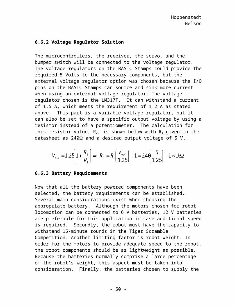
HoppenstedtNelson
11 APPENDIX C: Distance Calculation Considerations
The HYP command on the BASIC stamp calculates the hypotenuse of a right triangle given the values of the x and y components of said triangle by computing the sum of the squares of the x and y components, as shown below. This command will calculate distance, but the ranges of x and y are -128 to +127. This range is not suitable for the robot’s needs. The ranges of the pixel values of the field are as follows: x-position, 0 to 319, and y-position, 0 to 239. These are outside of the range of the HYP command, so some scaling will be necessary. This scaling is illustrated below.
This scaling will have a detrimental effect on precision. To determine whether this effect is catastrophic, some other information is necessary. Here, x and y are pixel values. As stated before, the x and y values are within certain ranges and the field has certain dimensions (8 ft x 6 ft). Using these numbers yields a distance of one-third of an inch between each pixel. Dividing the coordinates by four means that any two pixels that are up to four pixels apart will be seen as the same distance from the robot.
The HYP command will be used mainly for calculating any necessary distances. In particular, the HYP command will be used to calculate the distances necessary to select the closest ball to the robot. This case will be considered because the largest negative impact on performance caused by scaling will occur during selection of the closest ball. The error brought about by scaling means that the closest ball cannot always be selected because the closest ball cannot always be determined. The error margin needs to be determined in actual distance rather than pixel values to see the impact on performance caused by this error. If the distance between two pixels is one-third of an inch, and any two balls with distances from the robot that have a maximum difference of four pixels will be considered as the same distance from the robot, then the ball that is chosen as the
closest ball could actually be inches further away from the robot than the ball that is,
in reality, closest. So, the robot may travel inches further than the distance it would
have had to travel without this error, but the time taken to go inches is insignificant.
To show how insignificant the time taken to go this distance will be, a thorough inspection is required. The desired maximum speed of the robot is between 0.35 and 0.5 m/s. Using these two speeds, and assuming the robot is traveling at its maximum speed,
it would take between 67 and 97 ms to travel inches. This means that it will take
less than a tenth of a second to go the maximum extra distance introduced by scaling.
- 50 -
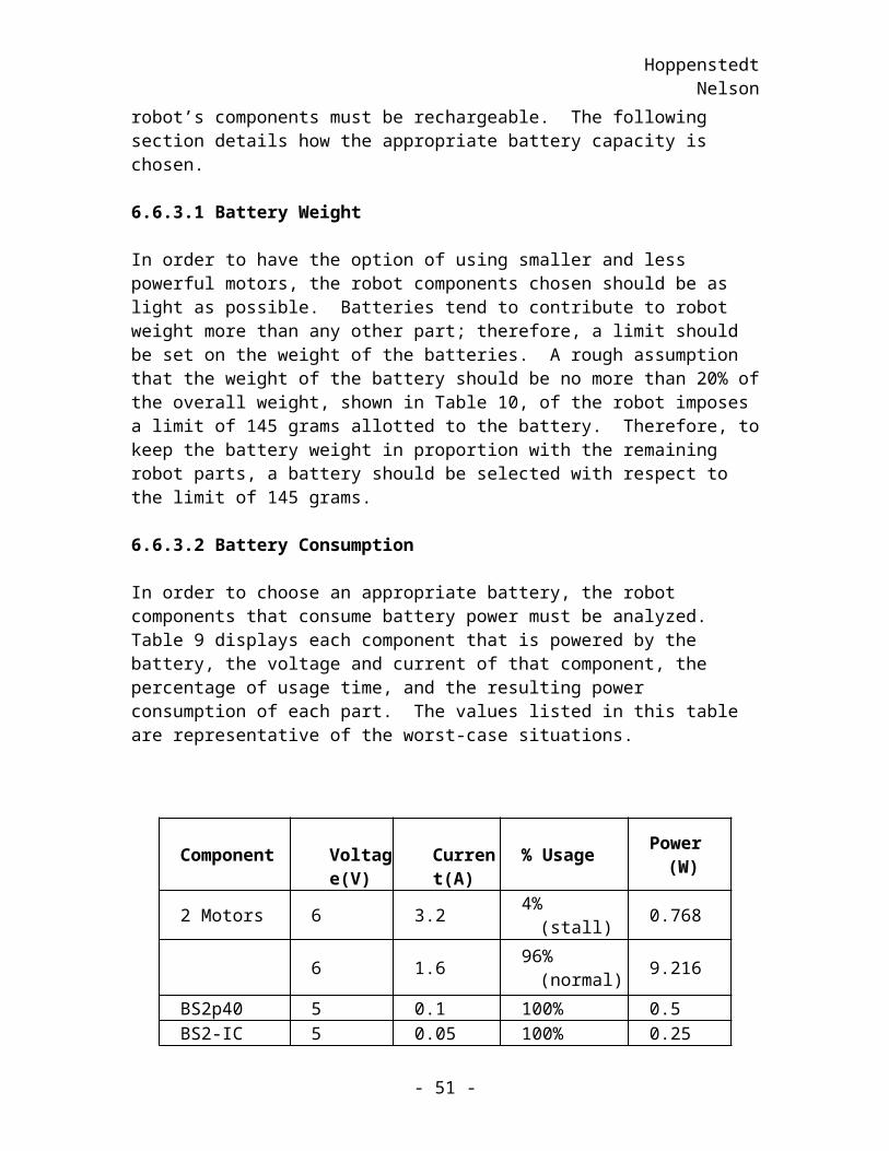
HoppenstedtNelson
It may be apparent to the reader that division by four is not necessary to make a number, which has a maximum value of 319, fit into the range specified by the HYP command. It is true that division by three would suffice to make the input values fit into the specified ranges, but division by four was chosen with good reason. This reason is exhaustively described in the following paragraphs. The first point to note is that division by four can be accomplished by logically shifting the binary representation of a number to the right by two bits. The second point to note is that dividing by three still results in an error margin of one inch. This is only an improvement of one-third of an inch over division by four. Following is a comparison of the time-saving ability of a lower computation time versus the time-saving ability of improved precision. This comparison will show why it was decided that dividing by four is better than dividing by 3 in this competition.
It is useful to use a shift rather than a division because the shift command on the BASIC stamp is faster than the divide command. The divide command on the BS2p takes 138 µs, whereas the shift command takes 108 µs. While 30 µs may not seem like much of an improvement, the HYP command will be used at least five times during the 100 ms interval in which the target ball is chosen. Each use of the HYP command requires two divisions, so in choosing the target ball, 10 divisions are required. Performing these 10 divisions as shifts will save a total of 300 µs. Note that 300 µs is 0.3% of the 100 ms window that is allotted for any computation. Still, it seems, at first, that this is a small improvement.
Deciding whether shifting is actually an improvement over division necessitates a look at the amount of time saved by improving precision. As stated previously, dividing by three, rather than four, shows a precision improvement of one-third of an inch. Using the maximum speed range stated previously, the time taken to go an extra one-third, of an inch is 17 to 24 ms. Taking the larger time as an example, 24 ms is 0.0027% of the 15-minute game time. Supposing that a match can be finished in one minute and looking at the time taken to do this extra movement for each of the three balls necessary for victory, this 72 ms is still only 0.12% of the total game time. The percentage of improvement in this case is smaller than the percentage of improvement in the previous case.
Basically, because computational time is more valuable than game time, i.e. we have less computational time than game time if we want all calculations to be done within a 100 ms time frame, it was decided that the time saved on the shift versus the divide was more worthwhile than the time lost by losing 25% accuracy in the worst-case distance calculations.
- 51 -
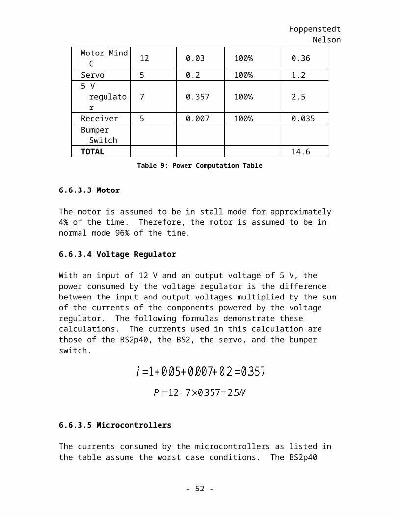
HoppenstedtNelson
12 APPENDIX D: BS2p Execution Time Estimates
To determine whether the BS2p would be fast enough to meet the needs of the robot, it was necessary to determine the speed at which the BS2p executes commands. The only microcontroller available for testing was a BS2. Without a BS2p to use in these measurements, some estimates had to be made. It was assumed that the BS2p was exactly three times faster than the BS2 in all cases.
To test the execution time of the BS2, the following code template was used:
‘Variable declaration and initializationStart:HIGH 1FOR counter = 1 to 10‘Code to be testedNEXTLOW 1GOTO Start
This code makes an infinite number of passes through the code between the “Start” label and the “GOTO Start” label. In each pass, pin one on the BS2 is set to high, the desired code is executed ten times, and then pin one is set to low. Note that counter is a variable declared at the start of the code.
While this code is running, pin one of the BS2 is connected to an input pin on an oscilloscope. The oscilloscope will display a five-volt signal while pin one is high and a zero-volt signal when the pin is low. Measuring the time that the five-volt signal is displayed, gives the time spent in one pass of the above code.
The time that the signal is at five volts is not the time taken to execute the command. The time taken to change the pin from high to low and the overhead associated with the loop must be taken into account. These times had to first be measured before they could be taken into account.
To measure the time taken to switch from high to low, the following code was used:
Start:HIGH 1LOW 1GOTO Start
This repeatedly changes the pin from high to low, and the time taken to make this change is easily measured. The time difference between the start and end of the five-volt portion of the signal is the time taken to switch from high to low. The time measured to switch pin one from high to low on the BS2 was 140µs.
- 52 -
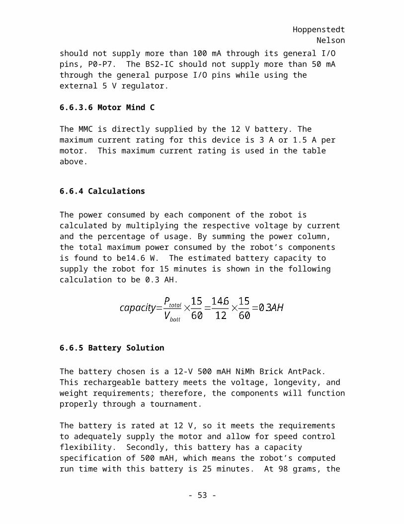
HoppenstedtNelson
The overhead from the loop was measured using the following code:
counter VAR ByteStart:HIGH 1FOR counter = 1 to 10NEXTLOW 1GOTO Start
Subtracting the switching time measured previously from the time that the signal was at five volts gave the time to execute the necessary instructions for the loop. The time measured was 7495 µs (7635 µs – 140 µs).
This, however, was not the end of the story. The fact that the BS2p is faster than the BS2 still had not been taken into account. To estimate the time that the BS2p would execute the code, the measured times were divided by three.
Combining the above information gave the following formula:
,
where tm is the time that the signal on the oscilloscope is at five volts.
With the above formulas, the task of measuring the execution times of the various routines could begin. Tentative versions of the code for each of the routines in Table 13 below were written and measured using the template at the beginning of this appendix.
Routine Execution Time (µs)Pick Ball 8,220Go To Ball 1,150Return To Goal 1,150Avoid Opponent 1,138
Table 13: BS2p Execution Time Estimates
- 53 -
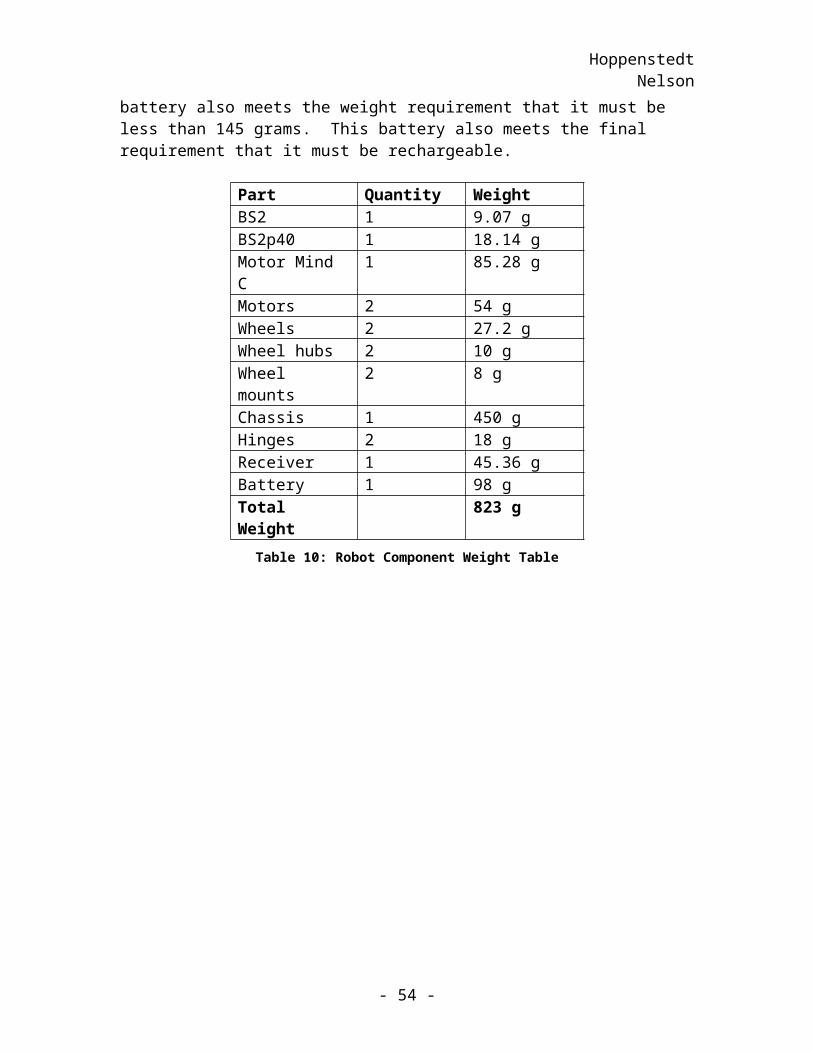
HoppenstedtNelson
13 APPENDIX E: Component Connections Defined
V I N3
A D J1
V O U T2
U 1
LM 3 1 7 / TO 2 2 0
S O U T1
S I N2
A TN3
V S S4
P 05
P 16
P 27
P 38
P 49
P 510
P 611
P 712
P 813P 914P 1 015P 1 116P 1 217P 1 318P 1 419P 1 520V D D21R E S _ N22V S S23V I N24
U 2
B S 2 I C
V _ re g
S O U T1
S I N2
A TN3
V S S4
P 05
P 16
P 27
P 38
P 49
P 510
P 611
P 712
P 813
P 914
P 1 015
P 1 116
P 1 217
P 1 318
P 1 419
P 1 520
X02 1X12 2X22 3X32 4X42 5X52 6X62 7X72 8X82 9X93 0X1 03 1X1 13 2X1 23 3X1 33 4X1 43 5X1 53 6V D D3 7R E S _ N3 8V S S3 9V I N4 0
U 3
B S 2 P 40
V _ re g
V M O T1
V M O T2
V M O T3
M 1-4
M 1-5
M 1-6
M 1+7
M 1+8
M 1+9
N C1 0
G N D1 1
G N D1 2
G N D1 3
A I N 1/ R C 11 4
A I N 2/ R C 21 5
N C1 6
N C1 7
N C1 8
N C1 9
TM2 0
V M O T4 0
V M O T3 9
V M O T3 8
M 2-3 7
M 2-3 6
M 2-3 5
M 2+3 4
M 2+3 3
M 2+3 2
N C3 1
F M2 1A D D R2 2N U M _ M O T2 3M O D E 02 4M O D E 12 5N C2 6N C2 7G N D2 8G N D2 9G N D3 0
U 4
M o t o r M in d C
V _ re g
B S 2 P 4 0 p in 5
V _ re g
B S 2 P 4 0 p in 1B S 2 P 4 0 p in 2B S 2 P 4 0 p in 3
V _ re g
G ro u n d
V _ b a t t
B S 2 P 4 0 p in 5
V _ re gV _ re g
B S 2 P 4 0 p in 6
V _ re g
B S 2 P 4 0 p in 15B S 2 P 4 0 p in 14
1k
1 k
G ro u n d
1 0 0 u
B S 2 P 40 p in 2 1B S 2 P 40 p in 2 2
G ro u n d
B S 2 P 40 p in 2 3B S 2 P 40 p in 2 4
1 k
4 7 047 0
1 0 k
B S 2 P 40 p in 2 5B S 2 P 40 p in 2 6
G ro u n d
B S 2 P 40 p in 2 7B S 2 P 40 p in 2 8
B S 2 P 4 0 p in 6
M ot o r1 -M ot o r1 -M ot o r1 -M ot o r1+M ot o r1+M ot o r1+
M o t o r2 -M o t o r2 -
R ec e iv e r
M o t o r2 +M o t o r2 -
V _ reg
M o t o r2 +M o t o r2 +
V _ reg
1kG ro u n d
B S 2 P 40 p in 2 1
1 kG ro u n d
G ro u n dG ro u n d
1 kG ro u n d
B S 2 P 40 p in 2 2
V _ reg
B S 2 P 40 p in 2 3
G ro u n d
G ro u n d
1 kG ro u n d
V _ b a t t
0
B S 2 P 40 p in 2 4
G ro u n d1 2 V
B S 2 P 40 p in 2 5
V _ b a t t
B u m p e r S w it c hS e rv o
B S 2 P 40 p in 2 6
B S 2 P 4 0 p in 1 5B S 2 P 4 0 p in 14
B S 2 P 40 p in 2 7
G ro u n d G ro u n d
B S 2 P 40 p in 2 8
1kG ro u n d I n 11
I n 22
I n 33
I n 44
I n 55
I n 66
I n 77
I n 88
O ut 11 6
O ut 21 5
O ut 31 4
O ut 41 3
O ut 51 2
O ut 61 1
O ut 71 0
O ut 89
U 5
S wit c h
1 kG ro u n d
Figure 27: Component Connection Schematic
- 54 -