Embed Size (px)
Citation preview

2
(Continuation Sheet)
Table of Contents
Table of Contents ........................................................................................................................ ..2 1. Statement of Problems Studied ............................................................................................... ..3 2. Summary of the Most Important Results ................................................................................ ..4 2.1. Development and Characterization of New MR Materials................................................. ..4 Introduction ................................................................................................................................. ..4 Experimental Study..................................................................................................................... ..6 Results and discussion................................................................................................................. 9 2.2. MR Damper Analysis, Design, Fabrication and Experimental Study................................. 12 Introduction ................................................................................................................................. 12 MR Damper Analysis Design ..................................................................................................... 15 Results and Discussions .............................................................................................................. 23 2.3. Full-Scale Study of Quarter-HMMWV-Model.................................................................... 26 Introduction ................................................................................................................................. 26 Theoretical Modeling .................................................................................................................. 26 Control Algorithms ..................................................................................................................... 28 Experimental Results .................................................................................................................. 30 3. List of Publications.................................................................................................................. 34 4. Scientific Personnel................................................................................................................. 37 5. Report of Invention ................................................................................................................. 37 6. References ............................................................................................................................... 37 7. Figures and Tables .................................................................................................................. 41

3
1. Statement of Problems Studied
The overall goal of this three-year project was to study the performance of novel, fail-safe,
magneto-rheological fluid (MRF) dampers by using innovative magneto-rheological (MR)
materials for off-highway, high-payload vehicles such as the U. S. Army’s HMMWV. In the
past three years, significant advances were achieved in the areas of: 1) MR materials
development, 2) theoretical modeling and experimental study of a new compact fail-safe MR
damper, including its design and development of a full-scale prototype, 3) a full-scale
experimental set up for quarter-HMMWV-model, and 4) control system development for the
nonlinear MR damper system.
A systematic approach was followed to unify all efforts for this integrated research. Several new
MR materials was developed and characterized that could be utilized in two new MR dampers
with the same overall geometric dimensions as a regular HMMWV damper. A unique full-scale
experimental set up was developed and tested. Extensive investigation was conducted on an
accurate control system taking to account variation of the MR fluid’s base viscosity and
temperature.

4
2. Summary of Most Important Results
2.1 Development and Characterization of New MR Materials
Introduction Magnetorheological fluids (MRFs) are suspensions of ferrous particles such as carbonyl iron
particles, which are micron sized, and dispersed in a carrier medium [1]. The carrier fluids can
be silicone oil, hydrocarbon oil or water depending on the specific application. In the absence of
an applied magnetic field, MRFs exhibit Newtonian behavior. They exhibit rapid, nearly
completely reversible rheological property changes when an external magnetic field is applied
(this is known as the on-state). In the on-state ferrous particles are magnetically induced and
aggregate to form chain-like or column-like structures parallel to the applied field. These
structures restrict the flow of the fluid thereby altering the rheological properties of the
suspension. The stress needed to yield these chain-like structures increases with applied
magnetic field resulting in a field dependent yield stress [2]. The rheological behavior of MRF is
often described by the Bingham plastic model [3].
To prevent the particles from settling or aggregating and allowing those to re-disperse more
easily in the carrier fluid different additives are used to modify the surface of the carbonyl iron
particles or to modify the viscosity of the carrier fluid. Carbonyl iron particles are usually coated
with surfactant to reduce settling in MR fluids [4]. Organic polymers are also been used to coat
the surface of iron particles [5].

5
In this research novel magneto-rheological-polymer gels (MRPGs) are investigated. MRPGs are
a new generation of materials used in vibration control and damping devices. Wilson [6] studied
MRPGs prepared by suspending iron particles in silicone gel or polyurethane gel. Adjusting the
ratio of resin to cross linker and percentage of diluent can control the off-state rheology of the
system. Xin also investigated static shear yield stress, off-state viscosity and sedimentation
properties of similar systems [7]. In this study, MRPGs with improved redispersion performance
and high temperature resistance property are investigated. This MRPG is a composite fluid of
magnetic particles suspended in a polyimide gel. Polyimides are thermo-oxidatively stable
materials with good chemical resistance. Polyimide gels contain cross-linked co-polyimide
(CCPI) swollen in excess solvent. It’s hard to stop the settling of iron particles completely since
the large difference between the density of iron particles and carrier medium. However, these
fluids can be used effectively in different devices, if they re-disperse quickly and completely.
Rabinow pointed out that complete suspension stability was not necessary for most MR fluid
devices since some devices such as MR dampers are very efficient mixing devices [8].
Therefore, re-dispersion of iron particles is very important issue in the investigation of MRPGs.
Stabilization and re-dispersion of the carbonyl iron particles in the carrier medium are attributed
to the adsorption of CCPI on the surface of the iron particles, thus sterically preventing the
particles from aggregating. One of the features of MRPG is its controllable off-state viscosity.
This is achieved through appropriate selection of carrier fluid and weight ratio of CCPI to
solvent. CCPI gels are synthesized from dianhydride, diamine, diaminobenzonic acid and 1-4
butanediol (cross-linker in the solvent N-octyl-pyrrolidone).

6
Another MRPG system, which is supramolecular polymer gel, is also studied. The erm:
“supramolecule” refers to a collection of atoms held together by covalent and non-covalent
bonds. Supramolecule polymer is composed by non-covalent bonding including hydrogen,
hydrophobic/hydrophilic, van der waals, metal coordination bond and other non-covalent bond.
Of these, metal-ligand bonds exhibit both strong and directional interactions where the selection
ion and ligand dictate association strength. The reversible nature of non-covalent bonds is
important in this research. It may improve the durability of MRPG because even though the
non-conalent bond is destructed by heat or shear stress it still can be reconstructed by self-
assembling after remove the heat and shear stress. The matrix for suparmaolecular MPPG is
based on zinc 2,2’; 6’, 2”-terpyridine based polymer.
Experimental Study
Materials Development:
1) Iron particles
Carbonyl iron particles were produced by ISP Technologies Inc (Grade-R-2430), which
comprise 99.5% pure iron and are formed by thermal decomposition of iron pentacarbonyl Fe
(CO)5. The size of these particles is about 5-7um.
2) Carrier fluids
The solvent is typically chosen based on its viscosity, freezing and boiling points and vapor
pressure. The solvent used is N-octyl-pyrrolidone (Aldrich Chemical Company, Inc.) which has

7
a boiling point of 306°C, viscosity of 9cp at 20°C and a vapor pressure of less than 1.3Pa at
20°C.
3) Polymer systems
a) Synthesis of Crosslinked Co-Polyimide:
The solvent N-octyl-pyrrolidone (OP) is introduced into a moisture free reactor. 3,5-
diaminobenzonic acid (DABA) (Aldrich Chemical Company, Inc.) is dissolved in the N-octyl-
pyrrolidone. The 4,4’-(4,4’-isopropylidene diphenoxy)bis(phthalic anhydride) (ISBPA) (Aldrich
Chemical Company, Inc.) is then added. This compound reacts for one hour at room temperature
to form an anhydride terminated pre-polymer. Reactive comonomer 4,4’-methylenedianiline
(MDA) (Aldrich Chemical Company, Inc.) is then added and mixed for 7 hours at room
temperature to form high molecular weight polyamic acids. Imidization is performed by
dehydration of the polyamic acid adding excessive acetic anhydride and N,N-dimethylaniline
(Aldrich Chemical Company, Inc.) to the reaction mixture and stirred for 2-3 hours at 50°C. The
temperature is then increased to 110°C for 30 minutes. This results in formation of linear co-
polyimide. To synthesize cross-linked polyimide gel, the cross-linker 1-4 butanediol (Aldrich
Chemical Company, Inc.) is added to the reaction mixture and kept at 170°C for 7 hours. The
crosslink ratio can be controlled by the stoichiometric ratio of diaminobenzonic acid to the 4,4’-
methylenedianiline used in the polymerization reaction. Synthesis of crosslinked polyimide is
shown in Figure 1.
b) Synthesis of supramolecule
To a suspension of KOH in DMSO, the poly(ethylene oxide) was added. After stirring for 1
hour at 60C, a’-chloro-2,2’;6’,2”-terpyridine was added. The mixture was stirred for 48 hours at

8
60C, then, after cooling the suspension was poured into cool water. A certain amount of white
precipitate was collected. Then, dissolving the precipitate into methanol, a solution of zinc
acetate in methanol was added drop wise at 60C. The color changed immediately to yellow.
With increasing metal ions, the viscosity of the solution raised slowly. The solution was put into
carrier fluid and the temperature was kept at 60C evaporating the methanol. The carrier medium
was formed. Synthesis of crosslinked supramolecule is given in Figure 2.
4) Synthesis of Crosslinked Polyimide and Supramolecular MRPG
a) Crosslinked polyimide MRPG
81 weight % carbonyl iron particles are added to the synthesized crosslinked polyimide gel and
mixed at low shear rate (400 rpm) using a Servodyne Mixer (model 50003-30, Cole Parmer
Instrument Company) for 30 minutes. Additives are mixed together and stirred thoroughly at
1200 rpm for 24 hours at room temperature.
b) Supramolecular MRPG
81 weight% carbonyl iron particles are added to the synthesized supramolecular gel and mixed
at low shear rate (400 rpm) using a Servodyne Mixer (model 50003-30, Cole Parmer Instrument
Company) for 30 minutes. Additives are mixed together and stirred thoroughly at 1200 rpm for
24 hours at room temperature.
Instrumentation
1) DSC

9
The DSC (Differential Scanning Calorimeter, Perkin Elmer, Pyris is used to investigate the
polymerization between monomers from room temperature to 300°C at a heat rate of 10°C/min.
DSC is also used to investigate the glass transition temperature which dictate the heat resistance
of polymer.
2) Shear Rheometer
The off-state viscosity of MRPF was measured using Brookfield Rheometer (Model DV-111,
Brookfield Engineering Laboratories Inc). The shear rate of the measurement is from zero to 85
1/sec.
3) DMA
A magneto-rheological rheometer (MCR300, Paar Physica Corporation) is used to investigate
fluid rheology [9]. The measurement system includes three parts: the mechanical drive system,
the electronics for data processing and a corresponding software package. Unlike a conventional
rheometer, the magnetic field applied to the MRPG is generated by a built-in copper coil. The
magnetic field is perpendicular to the gap filled with MRPG. The magnetic field (B) in the gap
depends on the current in the coil and the material in the gap through which the flux flows. Two
parallel disks with 20mm diameter and a 1mm gap are used for this study. Approximately 0.314
ml of sample is placed in the gap between the two plates. The plate-plate system, magnetic coil
and rotor shaft are shown in Figure 3.
Results and Discussion
1) Yield stress testing

10
A change in rheological behavior results from the polarization induced in the suspended particles
by application of an external magnetic field. These induced dipoles which cause the particles to
align “head to tail” in chains and form columnar structures, parallel to the applied field [10].
These chain-like structures hinder the flow of the fluid thereby increasing the apparent viscosity
of the suspension. The pressure needed to yield these chain-like structures increases with
applied magnetic field resulting in a field-dependent yield stress. Thus the behavior of this type
of controllable fluid in the post-yield region is often represented as a Bingham plastic having
variable yield strength, as follows:
.γητ τ += y , yττ ≥ (1)
Where τ is the total shear stress, τy is field-controllable shear yield stress, η is the viscosity of
the MRPG, and .γ is the shear strain rate. In the pre-yield region, MRPG behaves as a
viscoelastic solid, and therefore, the shear below the yield stress (at strains on the order of 10-3)
is given by:
γτ G= (2)
Where G is the complex material modulus and γ is the shear strain. It has been observed that the
complex modulus is also field dependent [11].
The effect of applied magnetic field on shear yield stress of the MRPG is investigated using the
MR rheometer described earlier. The results of the shear stress versus strain rate under different
applied magnetic flux densities for the MRPG are shown in Figure 4 and 5.
In Figure 6, dynamic yield stresses of two MRPGs and one commercially available MRF are
shown as functions of the applied magnetic flux density B. The yield stress increases

11
significantly with an increase of magnetic flux density and it is observed to increase with a B3/2
dependence, which is shown by the slope of 1.5 for the curve in Figure 9. The numerical and
analytical model was developed by Ginder et al.[11-13], as follows:
23
021
0 BM sy φµτ ∝ (3)
Where 70 104 −×= πµ Tesla-meter/ampere is the permeability in free space, φ is the volume
fraction of carbonyl iron particles, Ms is the local saturation of magnetization and B0 is the
magnetic induction related with the external field H0 by the following equation:
)( 000 sMHB += µ (4)
Therefore, the yield stress measured increases with a B03/2 dependence and agrees with the model
provided by Ginder et al. This sub quadratic dependence of flux density is a consequence of
local saturation of magnetization in the contact region of each particle.
In Figure 6, the CCPI:OP=1:20 system shows a slightly higher yield stress than the
CCPI:OP=1:40 system. It is speculated that this may occur because of improved dispersion
stability at higher polymer concentrations.
2) Apparent Viscosity Test
Apparent viscosity (ηapp), which is derived by the ratio between shear stress and shear rate,
decreases with increasing shear rate and is shown in Figure 7, 8 and 9. The phenomenon of the
decreasing apparent viscosity with increasing shear rate is known as shear-thinning behavior and
it is due to the presence of micron-sized particles. At higher shear rates the apparent viscosity
decreases, ultimately reaching a constant value. This shear-thinning phenomenon can be
represented by the following equation:

12
∆−
∝.γη app (5)
where ∆ is a constant, which may vary slightly with different field. The analytical and
experimental results show that the range of ∆ is from 0.68 to 0.93. magnetic field investigated.
2.2 MR Damper Analysis, Design, Fabrication and Experimental Study
Introduction
Cross-country performance of military off-road vehicles is a key element for success in military
operations. Cross-country performance can be determined by using different methods.
Maximum velocity and harshness of pitch and roll motions of vehicles under off-road conditions
can be used as parameters determining the cross-country performance [14]. Therefore, the
suspension system of these kinds of vehicles is closely related with the cross-country
performance characteristics on rough terrain.
Passive suspension systems using passive elements such as helical springs and viscous dampers
are designed to meet the requirements of conflicting demands, i.e., ride comfort, road holding
and handling. Active suspensions are one of the solutions used to improve the performance of
the suspension system. Studies related to active suspension systems started in the 1960’s [15].
They can improve the ride quality, road holding and handling characteristics significantly by
controlling the damper force compared to the passive suspensions [15,16,17]. Experimental
results conclude that the power absorbed by the driver is reduced by 95% and a 65% reduction is
obtained in peak sprung mass acceleration by using an active suspension system for the
HMMWV [16]. However, complexity of the design, high power requirements, weight and cost
are the disadvantages of using active suspensions. Semi-active dampers are devices combining

13
the advantages of passive and active dampers. Indeed, they are much simpler than active
dampers and have better performance characteristics than passive dampers therefore, there are
many researches, started by the early 1970’s, studying semi-active dampers [14,18,19,20].
Experimental studies done on the US Army M551 tank show that the power absorbed by the
driver is reduced by 43% by consuming virtually no power with respect to the active suspension
systems [20]. Many of the studies on semi-active suspension systems consider dampers using
electro-hydraulic valves but recently magneto-rheological fluid (MRF) dampers have also been
studied for military and passenger ground vehicles [21,22,23]. Experimental studies done on the
HMMWV prove that the power absorbed by the driver is reduced up to 70% [21]. MRF dampers
do not need any movable valve to change a force characteristic of the damper. On the other
hand, they use the unique characteristic of a MR fluid; that is controllability of effective viscosity
by applying an external magnetic field to valves.
Recently, an MRF damper for a High Mobility Multi-Purpose Wheeled Vehicle (HMMWV) has
been developed at the Composite and Intelligent Materials Laboratory in the Mechanical
Engineering Department of the University of Nevada, Reno (UNR) [23]. This study is the
benchmark for our current research. This study concluded that the force of the MRF damper can
be increased by keeping the uncontrolled force the same as the original equipment manufacturer
(OEM) damper for the HMMWV. However, the damper, which has been developed for that
study needed some modifications in terms of its feasibility for real life applications. Force
characteristics, size, and power consumption of the damper had to be optimized.
Therefore, this study is aimed toward the design, fabrication and evaluation of the performance
of a new MRF damper for the HMMWV. The main objective of the new design is to develop an

14
MRF damper that is feasible to use for the HMMWV in terms of force characteristics, size and
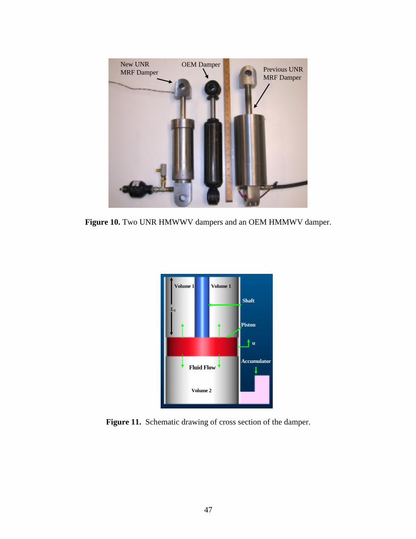
power consumption of the damper. Figure 10 shows three different dampers developed for the
HMMWV. The new MRF HMMWV damper is on the left, and the previous MRF HMMWV
damper is on the right and an OEM HMMWV damper is in the center.
A new damper is designed as a fail-safe damper i.e. the damper can supply enough damping in
the case of control system or power supply failure. This phenomenon is crucial for off-road
vehicles since malfunction of the control system can cause severe damages to the vehicle or
passengers when a vehicle is on rough terrain unless the viscous (off-state) force of a damper is
enough. To determine the off-state force, the OEM damper force is taken as a reference point, as
in the previous study; however, the off-state force is not exactly matched with the OEM damper
force. The off-state force is optimized by keeping it smaller than the OEM damper force; while
at the same time keeping the ride and stability characteristics in safe levels. By lowering the off-
state force to optimum values, the controlled force region is increased for a desirable better ride
quality.
A new damper is designed to match the geometrical parameters, such as, outer diameter,
extended and compressed lengths of the OEM damper. In addition to that, the new damper is
designed to operate with the vehicle’s battery.
Another important objective of this research is to obtain different viscous force characteristics
between the rebound and the compression phases, as in the OEM viscous dampers for ground
vehicles. Non-symmetric characteristic has been obtained by using two-way valves [24]. Ivers

15
at al. presented movable and one-way valves to obtain a non-symmetric characteristic. In our
study, instead of changing the piston geometry for different flow directions, shims are used to
provide the non-symmetric force behavior between rebound and compression. They are very
simple and inexpensive to use.
MRF Damper Analysis and Design
Figure 11 illustrates the inside of the MRF damper. The proposed MRF damper is not a through
shaft damper, therefore, an accumulator is connected to volume 2 to compensate for the volume
change due to the movement of the shaft. The force characteristic of a damper is directly related
with the pressure drop through the piston. Piston geometric parameters, i.e., the sizes and
locations of orifices and electromagnet, determine the pressure drop through the piston.
Therefore, every component of the piston geometry design is explained in detail in the following
sections. First, fluid flow analysis through the piston is formulated, then, pressure drops and
force calculations are explained.
a) Flow rate through the piston
The mass flow rate for a control volume containing incompressible fluid can be written as [25]:
)()()( oiooii QQQQVdtdm
dtd −⋅=⋅−⋅=⋅= ρρρρ (6)
where m is the mass of the fluid inside the control volume, ρ is the fluid density, taken as
constant for inlet and outlet conditions, V is volume, Q is volume flow rate, and subscripts i and
o represent inlet and outlet, respectively. Rebound and compression phases of a cycle are
considered below.
16
Rebound phase,
Equation (6) is applied to the volume 1 (V1) of the damper. For the rebound phase Qi = 0;
therefore, Equation 6 reduces to,
01 Q
dtdV
−= (7)
The geometric relations within the damper yield,
)()( 11 sp AAuLV −⋅−=
)(1sp AAu
dtdV
−⋅−= D (8)
where u is the piston displacement, uD is the piston velocity, Ap is the cross sectional area of the
piston and As is the cross sectional area of the shaft. Then, the flow equation for the rebound
case can be derived by using Equations (7) and (8),
uAAQ sp D⋅−= )( (9)
Compression phase
The same flow rate, in Equation (9) can be derived for the compression case using the same
procedure above. Therefore, the flow rate formulation for rebound or compression can be used
as a general flow rate formulation.
b) Pressure Drop Equations
Pressure drop due to the viscosity of the fluid obtained assuming an incompressible Newtonian
flow through the orifices. In the new MRF damper design, a gap between two parallel fixed
disks with radial flow is used as the main MR valve in addition to these common orifices as
17
viscous channels. Figure 12 shows the cross-sectional view of the piston in which all orifices
can be seen.
The MR valve is created when an external magnetic field is applied to control the flow behavior
in a channel. The effect of material properties and the geometry on the magnetic filed are
examined to enhance the controllable pressure drop due to MR effect. Parallel disk type MR
orifice, which can be seen in the Figure 13, used in this design also introduces uncontrollable
viscous pressure drop. This pressure drop together with the other viscous channels creates the
minimum damping force in the inactivated state (off state), which is the fail-safe criteria adopted
for this design.
b.1) Pressure Drop due to the MR Effect
The flow rate equation between the fixed rectangular parallel plates is derived and is converted
to the flow rate equation between two parallel fixed disks. The following equation describes the
flow between the fixed rectangular parallel plates considering the Bingham Plastic model [26],
0)(4)(]312[)( 323
3 =⋅+⋅⋅+⋅
⋅⋅−hdx
dphhb
Qdxdp yy ττµ (10)
where dxdp is the pressure drop per unit length of plates, b is the width of the plates, h is the gap
thickness between the plates and yτ is the controllable yield stress of the fluid. From equation
(10) one has, [27],
31285.2
hbQ
hdxdp y
⋅⋅⋅+⋅= µτ
(11)
18
To apply the above formula for the flow between two parallel fixed disks, the following
correspondences of symbols are made [28,29]
Then the radial pressure gradient is obtained as,
3
685.2hrQ
hdrdp y
⋅⋅⋅⋅+⋅=
πµτ
(12)
Integrating Equation (12) gives
)(85.2 12 rrh
P ymrdisk −⋅⋅=∆
τ (13)
)ln(6
1
23 r
rh
QPvisdisk ⋅
⋅⋅⋅=∆
πµ (14)
where r2 and r1 are the outer and inner radius of the disks.
b.2) Pressure Drop Through the Viscous Orifices
Circular cross section
The pressure drop in the cylindrical viscous channel for the flow of an incompressible
Newtonian fluid is well known and it is given as
LD
QPvis ⋅⋅
⋅⋅=∆ 41128
πµ (15)
where D is diameter of the orifice, L is length of the orifice, Q is flow through the orifice and µ
is viscosity of the fluid.
drdp
dxdp
rb
→
⋅⋅→ π2
19
Rectangular cross section
For flow in rectangular cross section, one has
Lhw
QPvis ⋅⋅
⋅⋅=∆ 3212 µ
(16)
where w is width of the channel and h is height of the channel. The gap between the two
cylinders produces
LC
QPvis ⋅⋅
⋅⋅=∆π
µ23 (17)
where,
)(2
)(4
)lnln(24
21
22
221
22
11
212
22
14
14
2 rrcrrcrrrrcrrC −⋅+−⋅+⋅−⋅⋅−−=
21
22
21
1 lnln rrrr
c−−
=
21
12
222
12 lnln
lnlnrr
rrrrc
−⋅−⋅
=
r1: radius of the inner cylinder, r2: radius of the outer cylinder.
Therefore, the total viscous drop is obtained by combining Equations (15)-(17), as shown below:
321 visvisvisdiskvis PPPPPvis
∆+∆+∆+∆=∆ (18)
b.3) Pressure Drop due to the Minor Losses
Minor losses, refer to energy losses associated with miscellaneous fittings: elbows, expansions,
etc. They are considered as minor losses in long pipe systems but in damper applications due to
the short length of the orifices, they may become major losses [30]. Therefore, minor losses

20
have to be taken into account in the pressure drop calculations. The pressure drop associated
with minor losses are calculated using the following formula,
2
2VKP Lm
⋅⋅=∆ ρ (19)
where KL is the overall minor pressure drop coefficient, ρ is the fluid density and V is the
average velocity of the fluid.
b.4) Pressure Drop Due to the Shims
Shims are used in the HMMWV OEM damper in order to achieve non-symmetric force
characteristics. The energy loss is greater in the rebound phase compared to the compression
phase. In this research, the same method is used to achieve non-symmetrical force
characteristics. Shims are only placed on the top portion of piston. The pressure drop due to the
shims is assumed to be the following form:
VCVCPs ⋅+⋅=∆ 22
1 (20)
where C1 and C2 are the coefficients depending on the material, shape and number of shims and
V is the velocity of the piston.
c) Electromagnetic Analysis
The magnetic field distribution inside the MRF damper is evaluated using ANSOFT finite
element analysis (FEA) software. A three-dimensional model of the damper, which can be seen
in Figure 14, is developed and Ansoft software is used for specified boundary conditions that
include material properties, electromagnetic activation current, and element insulation. A
relationship between electromagnet activation current and magnetic field strength is determined
using this software.

21
The geometrical parameters optimized in the electromagnetic analysis part can be seen in Figure
15. They are the coil width, MR disk radius and MR disk thickness. Since the outer diameter of
the damper is one of the design constraints, taken as the OEM damper outer diameter, coil width
and MR disk radius need to be optimized in this limited space. Ansoft is used to solve different
piston models with different values for the coil width and MR disk radius. A combination giving
the greatest MR force is selected. After optimizing the coil width and MR disk radius values, the
MR disk thickness is determined. Different MR disk thickness values give different magnetic
flux density values inside the MR channel; Figure 16 shows the relation obtained between
magnetic flux density and MR disk thickness. Based on the results presented in Figure 16, a
thickness between 1-3 mm, is selected as a desired value of MR disk thickness. Table 1 shows
all the parameters related with the electromagnetic analysis.
c.3) Electromagnetic Analysis Results
Using the final design parameters, electromagnetic analysis is performed for different electrical
current inputs. Figure 17 shows the magnetic flux density values inside the MR channel as a
function electrical current input. Theoretically, 0.65 T is achieved inside of the MR channel and
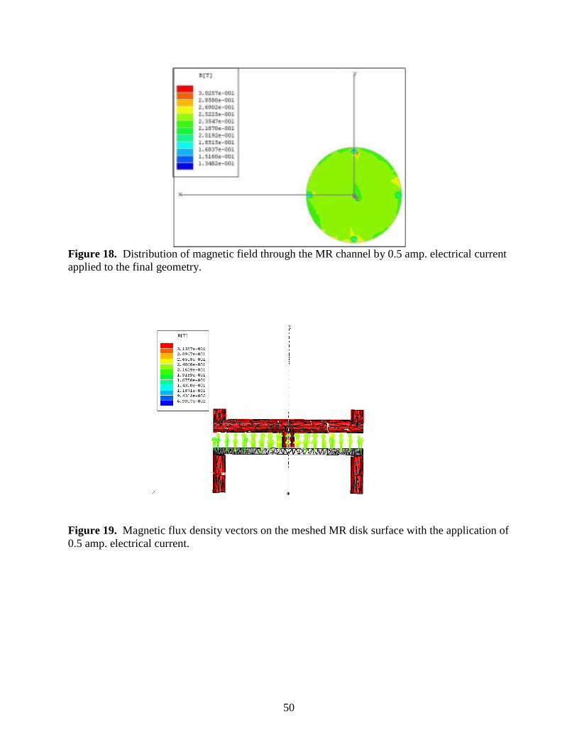
it is uniformly distributed due to the symmetry and the disk type MR channel. Figure 18 shows
the distribution of magnetic field inside the MR channel. In addition to this, the magnetic flux
density vectors on the MR disk surface, as well as, the mesh used in the solution can be seen in
Figure 19.

22
By using the dimensions obtained from the electromagnetic analysis, electromagnet coil
resistance is 3.5 ohm. which is a low resistance. This allows to apply currents as high as 2 or 3
Amp and therefore, a low electrical power.
d.4) Damper Force
Force of the damper can be written as
)(2211 usignFAPAPFd f D⋅+⋅−⋅= (21)
where fF is the seal friction force
mvisrrdisk PPPPPPPmr
∆+∆+−+∆=− )(2121 (22)
In determining 2P , nitrogen gas inside of the accumulator is assumed as an ideal gas. This
provides:
γγaaoo VPVP ⋅=⋅ (23)
where Po is initial pressure of the accumulator, Vo is initial volume of the accumulator, Pa is final
pressure of the accumulator, Va is final volume of the accumulator, γ is coefficient of thermal
expansion (1.4~1.7 for adiabatic expansion). In this study, 1.4 is used for thermal expansion
coefficient in this study.
In addition, conservation of mass for an incompressible fluid yields:
uAVV soa ⋅=− (24)
where As is cross sectional area of the shaft. Combining Equations (23) and (24) gives;
γ))(
(usignuAV
VPPso
ooa
D⋅⋅+⋅=
Since it is assumed that P2=Pa, using the Equation (22) the damper force can be expressed as by:
23
)())(( 21min usignFAPAPusignPPPF faadiskorvisd mrDD ⋅+⋅−⋅+⋅∆+∆+∆= (25)
Result and Discussion
Two different MRF damper dampers were designed, fabricated and tested. They are named
UNR-MRD-005-1 and UNR-MRD-005-2. Characterization experiments are focused on
investigating the effects of using shims inside the damper and the MR properties of the MRF on
the force-displacement and force-velocity behavior of the damper. Experimental results are
presented in two different sub-sections to point out these two different effects separately. After
the experimental results are presented, theoretical and experimental results are compared. A
comparison is made separately for the off-state and on-state cases of the MRF damper.
1. Effect of Shims
The test results of the MRF damper with and without shims are presented. Four different shaped
shims are used to analyze the effect of using shims. From the test results, it is concluded that
shims do not change the compression force but they increase the rebound force of the damper.
Experimental Results of the UNR-MRD-005-1
Figure 20 and Figure 22 (a) shows the effect of using shims on UNR-MRD-005-1 force
characteristics. Although compression force almost remains constant, rebound force increases
200% when shims are used.
Experimental Results of the UNR-MRD-005-2
Figure 21 and Figure 22 (b) shows the effect of using shims on UNR-MRD-005-2 force
characteristics. Compression force remains constant for UNR-MRD-005-2. On the other hand,
24
increase in the rebound force is less for UNR-MRD-005-2. Therefore it is concluded that, effect
of shims is a function of fluid velocity.
2. MR Effect on the Damper Force Characteristics
In this section, force-displacement and force-velocity behaviors of the UNR-MRD-005-2 with an
applied current to the damper are analyzed. The OEM damper force characteristics with the off-
state force characteristics of the UNR-MRD-005-2 are compared. Dynamic force range of the
damper is also presented. From the experimental results it is concluded that the activation of the
damper with electrical current increases the force of the damper both in rebound and
compression phases. Dynamic force range of the damper can be seen in Figure 25. For the
rebound phase, up to 16 times higher forces can be obtained from the damper with a 3.14 cm/s
piston velocity. For the compression phase, 20 times higher force can be obtained from the
damper with the same piston velocity. The ratio of the full on-state force to off-state force
decreases when the piston velocity increases.
3. Theoretical Estimations
Theoretical estimations are obtained from the fluid mechanics and electro-magnetic based model.
Fluid mechanics based model estimations are analyzed separately from electro-magnetic analysis
model. For this reason, viscous (off-state) force estimations and on-state force (summation of
the viscous and MR force) are compared separately and presented in Figure 26 and 27,
respectively. From the comparison, it is concluded that, the theoretical estimations are in a good
agreement with the experimental results. Deviation from the experimental results is mainly due
to the air inside of the damper.
25
Conclusions The second generation HMMWV MRF damper is improved with respect to the first generation
HMMWV damper in terms of many different properties. First of all, the new damper has been
designed by considering the feedbacks coming from the full-scale quarter HMMWV model.
Therefore, it has been proved that the new HMMWV MRF damper is a fail-safe damper and
gives better ride quality with respect to the HMMWV OEM damper in the full-scale quarter
HMMWV test setup. Second, as a first time in the literature, shims are used in an MRF damper.
They are used to achieve a non-symmetrical force characteristic between the rebound and
compression phases. It is concluded that, for this specific piston and shims geometry, the
rebound force can be increased while keeping the compression force same by using shims.
Therefore, one can produce non-symmetrical force characteristics by using shims. Third, the size
of the new damper is reduced down tremendously. The new damper fits inside the original
HMMWV suspension spring. Therefore, this damper can be used in the real life applications.
This improvement is established by using a more efficient MR orifice, which is a disk type
orifice, created by using the gap between two fixed cylinders. Fourth, the maximum power
consumption of the new MRF damper is only 31.5 W, which is a very small amount of power
consumption for vehicle applications. For the first generation damper, it was 178 W. This result
is closely related with the applicability of the new damper for the real life applications as well.
This great improvement is also directly related with using a disk type MR orifice. Lastly,
theoretical estimations are in good agreement with the experimental results.
26
2.3. Full-Scale Study of Quarter-HMMWV-Model
Introduction
The design of a vehicle suspension system requires a compromise between vehicle handling and
passenger comfort. Vehicle suspension systems supports the weight of the vehicle, provide
directional control during handling maneuvers and should have the ability to decrease the
vibration subjected to passengers and payload created by road disturbances. A conventional
vehicle suspension system usually consists of a spring and a damper. The level of ride quality is
determined by the amount of energy dissipation by the damper per cycle and the amount of
energy stored and released by the spring. A large amount of energy dissipation usually causes
harsh or uncomfortable ride, although it is beneficial for off-road driving. Controllable
suspension systems are considered to be a way of minimizing the compromise between the ride
quality and the handling of the vehicle. The characteristics of a controllable suspension system
can be adjusted on demand either automatically or manually for any given road profile.
Theoretical Modeling
A two DOF quarter car model is used to study the performance of the dampers as shown in
Figure 28. The vehicle mass with passengers is represented by sprung mass ms and the masses
of the suspension components and the wheel are represented by an unsprung mass mu. The
independent motion of the sprung mass is the first DOF, which is called as “body bounce” and
motion of the unsprung mass is the second DOF. The vertical motion of the system can be
defined as x1 and x2, which are the displacements of sprung and unsprung mass, respectively.
The input is defined as xr, which is the excitation due to the road profile. The suspension spring
constant is k1 and the stiffness of the tire is k2. The damping coefficient of the shock absorber is

27
described by c. The damping coefficient of the tire has been neglected since it has a very high
stiffness value.
The equations of motion for the two DOF OEM system can be written as follows:
0).().(. 212111 =−+−+••••
xxcxxkxms (26)
0).().(. 212112 =+−−−−••••
Fxxcxxkxmu (27)
where ( ) ( )
( ) ( )
−<++−≥+−
=r
rr
xxkgmsmugmsmuxxkgmsmuxxk
F22
2222 is the change in the spring force from the
static equilibrium condition. The equation of motion should be modified for the MRF damper
case. The ).( 21
••− xxc term should be replaced with the controllable MRF force:
0).(. 2111 =+−+••
MRFdamperFxxkxms (28)
0).(. 2112 =+−−−••
FFxxkxmu MRFdamper (29)
MRForceceViscousForFMRFdamper += (30)
The MRF damper force consists of a viscous damping force and the force due to MR fluid
activation. The viscous force is present even in the absence of the magnetic field. The MR force
is the controllable force component and can be varied by a control system. A control algorithm
and a mathematical model should be utilized to determine the appropriate magnetic field

28
required to generate necessary MR force. Table 2 presents system parameters for the full-scale
quarter HMMWV Model.
Control Algorithms
On-off and continuous skyhook control algorithms are utilized to control the MRF damper. In
skyhook control, a fictitious damper is connected to inertial reference in the sky. Figure 29
illustrates the skyhook-controlled damper used in the quarter car model.
The control condition criteria for the on-off skyhook algorithm is the product of the absolute
velocity of the sprung mass ( 1•x ) and the MRF damper relative velocity ( 21
••− xx ). If )( 211
•••− xxx is
greater than 0, then the pre-determined constant current (0.5 amp) is supplied to the MRF
damper. On the other hand, if )( 211•••
− xxx is equal or less than 0, then no current is supplied to
damper, and in this case, MRF damper has the same characteristic as the passive-off damper.
The on-off skyhook control rule can be expressed, as follows:
≤−→
>−→=
•••
•••
0)(0
0)(
211
211
xxx
xxxFF c
MR (31)
Where cF is a constant force.
In continuous skyhook control, the MR force is not switched between 0 and constant value. The
MR force varies between minimum and maximum force values, which are 0 N and 3500 N,
respectively, for this particular MRF damper design. The control condition criteria of continuous

29
skyhook is similar to on-off skyhook control, the only difference is the applied force. If
)( 211•••
− xxx > 0, the force is proportional to sprung mass absolute velocity. For this case, the MR
damper force is equal to the product of sprung mass velocity and predetermined damping
coefficient (cs), which is also known as the skyhook damping coefficient. The skyhook damping
coefficient (cs) is determined experimentally as 5000 N.s/m. If )( 211•••
− xxx is equal to or less than
0, the MR damper force changes depending on the MRF damper velocity ( 21••
− xx ). The
continuous skyhook control rule can be expressed as follows:
→>>−→=
••••
OtherwiseceViscousForceViscousForxcxxxxcF ss
MRFdamper12111 &0)(. D (32)
Experimental Setup
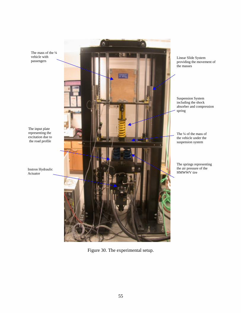
A full-scale quarter car HMMWV experimental setup is constructed to study the performance of
the OEM damper and the new semi-active MRF damper. An Instron 8821S servo-hydraulic
system is used to provide the input road profile. The actuator of the hydraulic unit is mounted to
a plate ( rx ), which is exciting the masses and the suspension system shown in Figure 30.
Four identical springs are used to model the rear tire stiffness (k2) and mounted to sprung mass
(mu) in parallel. The springs representing the tire are not mounted to the input plate, so that the
possibility of tire losing its contact can be modeled for further experimental analysis of tire hop.
A steel plate has been used to represent the mass of the components located under the suspension
system. The suspension system is located between the sprung and unsprung masses. The
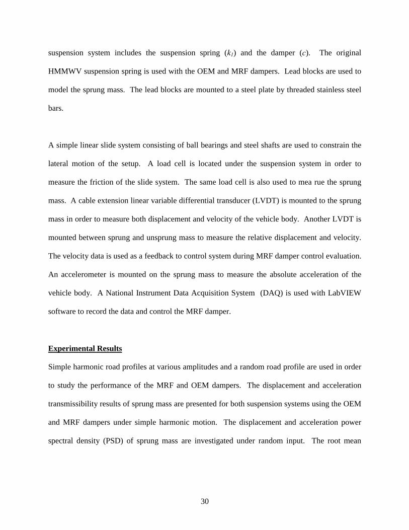
30
suspension system includes the suspension spring (k1) and the damper (c). The original
HMMWV suspension spring is used with the OEM and MRF dampers. Lead blocks are used to
model the sprung mass. The lead blocks are mounted to a steel plate by threaded stainless steel
bars.
A simple linear slide system consisting of ball bearings and steel shafts are used to constrain the
lateral motion of the setup. A load cell is located under the suspension system in order to
measure the friction of the slide system. The same load cell is also used to mea rue the sprung
mass. A cable extension linear variable differential transducer (LVDT) is mounted to the sprung
mass in order to measure both displacement and velocity of the vehicle body. Another LVDT is
mounted between sprung and unsprung mass to measure the relative displacement and velocity.
The velocity data is used as a feedback to control system during MRF damper control evaluation.
An accelerometer is mounted on the sprung mass to measure the absolute acceleration of the
vehicle body. A National Instrument Data Acquisition System (DAQ) is used with LabVIEW
software to record the data and control the MRF damper.
Experimental Results
Simple harmonic road profiles at various amplitudes and a random road profile are used in order
to study the performance of the MRF and OEM dampers. The displacement and acceleration
transmissibility results of sprung mass are presented for both suspension systems using the OEM
and MRF dampers under simple harmonic motion. The displacement and acceleration power
spectral density (PSD) of sprung mass are investigated under random input. The root mean

31
square (RMS) of both displacement and acceleration for the sprung mass are presented. The
MRF damper experimental results are compared with the OEM damper results.
The acceleration transmissibility shown in Figure 31 includes experimental data for 1 cm peak-
to-peak amplitude simple harmonic motion. From the acceleration transmissibility data, Table 3
is generated to present the percentage of peak acceleration transmissibility reduction provided by
the MRF damper as compared to the OEM damper. It should be noted that the sprung mass
acceleration is the critical parameter in determining vehicle ride quality. The reduction in sprung
mass acceleration increases vehicle ride quality.
The acceleration transmissibility results indicate that the ride quality of the quarter car model
vehicle can be improved by utilizing skyhook controlled MRF dampers. In addition to this
acceleration reduction, the MRF suspension system also offers fail-safe performance, where the
MRF damper functions similar to the passive OEM damper in case of a control system
malfunction.
A MRF suspension system using both on-off skyhook and continuous skyhook control has very
significant acceleration reductions under simple harmonic road inputs.
Figure 32 shows the displacement transmissibility graphs of sprung mass for OEM damper and
MRF damper suspension system. The displacement transmissibility behavior is very similar to
the acceleration response. Based on these results, a continuous skyhook controlled MRF damper
suspension system out performs one with skyhook on-off control. The reason is simply the
32
variable controllability range of the MR force between the maximum and minimum operating
points of the MRF damper under continuous skyhook control offer more adjustability to the
suspension system as compared to the on-off control strategy. Table 4 presents the displacement
transmissibility reduction of sprung mass for the MRF damper system as compared to the OEM
damper suspension system.
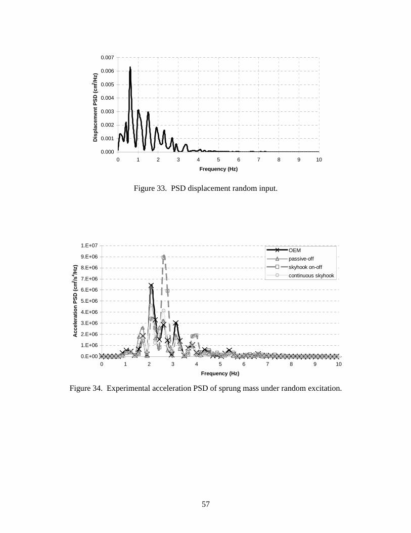
The random input is generated by MATLAB software by using the following relation [31]:
mVWxVx =+.
ρ (33)
Here x and .x are displacement and the velocity of the random input, respectively, ρ is the road
roughness parameter, Wm is the white noise that is proportional to velocity of the vehicle V, and
roughness of the road.
The velocity of the vehicle is selected as 64.5 km/h (40 mph) and the road roughness is 0.45 m-1.
The displacement power spectral density (PSD) of the road profile is presented in Figure 33.
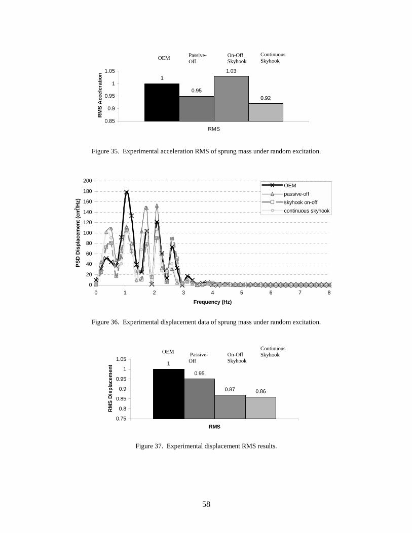
Figure 34 presents the acceleration PSD of the sprung mass for the random motion input. Based
on the results shown in Figure 35, the ride quality is improved by 8% utilizing MRF damper with
continuous skyhook control. In addition, vehicle body acceleration does not increase in case of a
control system failure.
Figure 36 shows the displacement PSD of sprung mass under random motion input. Based on
Figure 37, a sprung mass displacement reduction of 14% can be created by the MRF damper
system using continuous skyhook control. The MR fluid damper with on-off skyhook control
also exhibits better results than OEM damper for displacement PSD response. There is no

33
increase in displacement for passive-off case. The damper is considered to be fail-safe and
provides displacement reduction with or without a control system.

34
3. LIST OF PUBLICATIONS Published 1. Gordaninejad, F. and Kelso, S. P., “Magneto-Rheological Fluid Device,” U.S. Patent No.
6,471,018 B1, 2002. 2. Fuchs, A., Xin, M., Gordaninejad, F., Wang, X., Hitchcock, G., Gecol, H., Evrensel, C.,
and Korol, G., "Development and Characterization of Hydrocarbon Polyol Polyurethane and Silicone Magnetorheological Polymeric Gels," Journal of Applied Polymer Science, Vol. 92, issue 2, pp. 1176-1182, 2004.
3. Dogruer, U., Gordaninejad, F., and Evrensel, C., "A Magneto-Rheological Fluid Damper
for High-Mobility Multi-Purpose Wheeled Vehicle (HMMWV)," Damping and Isolation, Proceedings of SPIE Conference on Smart Materials and Structures, Ed. Kon-Well Wang, Vol. 5386, pp. 195-203, 2004.
4. Karakas, S., Gordaninejad, F., Evrensel, C., Yeo, M-S, Liu, Y., and Sahin, H., "Control of
a Quarter HMMWV Suspension System Using a Magneto-rheological Fluid Damper," Damping and Isolation, Proceedings of SPIE Conference on Smart Materials and Structures, Ed. Kon-Well Wang, Vol. 5386, pp. 204-213, 2004.
5. Liu, Y., Gordaninejad, F., Evrensel, C., Karakas, S., and Dogruer, U., "Experimental Study
on Fuzzy Skyhook Control of a Vehicle Suspension System Using a Magneto-Rheological Fluid Damper, " Industrial and Commercial Applications of Smart Structures Technologies, Proceedings of SPIE Conference on Smart Materials and Structures, Ed. by Jack H. Jacobs, Vol. 5388, pp. 338-347, 2004.
6. Dogruer, U., Gordaninejad, F., and Evrensel, C. A., “A New Magneto-Rheological Fluid
Damper for High-Mobility Multi-purpose Wheeled Vehicle (HMMWV),” Proceedings SPIE Smart Structures and Materials Conference, Damping and Isolation, Ed. By A. S. Agnes and K-W Wang, Vol. 5052, pp.198-206, 2003.
7. Liu, Y., Gordaninejad, F., Evrensel, C. A., Dogruer, U., Yeo, M-S , Karakas, E. S., and
Fuchs, A., “Temperature Dependent Skyhook Control of HMMWV Suspension Using a Fail-Safe Magneto-Rheological Damper,” Proceedings SPIE Smart Structures and Materials Conference, Industrial and Commercial Applications, Ed. by E. H. Anderson, Vol. 5054, pp. 332-340, 2003.
8. Karakas, E. S., Gordaninejad, F., Evrensel, C. A., Yeo, M-S, and Liu, Y., “Study of A
Quarter Model HMMWV Suspension System Using A Magneto-Rheological Fluid Damper,” Proceedings SPIE Smart Structures and Materials Conference, Smart Structures and Integrated Systems, Ed. By A. M., Baz, Vol. 5056, pp.506-513, 2003.

35
9. Wang, X. and Gordaninejad, F., “Dynamic Modeling of Semi-Active ER/MR Fluid Dampers,” Damping and Isolation, Proceedings of SPIE Conference on Smart Materials and Structures, Ed. Daniel J. Inman, Vol. 4331, pp. 82-91, 2001.
Submissions to Journals 1. Liu, Y, Gordaninejad, F., Dogruer, U., and Evrensel, C. A., “Theoretical Study on
Temperature Compensated Skyhook Control of a Vehicle Suspension Using Failsafe Magneto-Rheological Fluid Damper,” submitted for publication.
2. Fuchs, A. Hu, B., Gordaninejad, F., and Evrensel, C., "Investigation and Development of
Magneto-rheological Polymeric Materials for High-Payload Land Vehicles," submitted for publication.
3. Dogruer, U., Gordaninejad, F., and Evrensel, C., "A Magneto-Rheological Fluid Damper
for High-Mobility Multi-Purpose Wheeled Vehicle (HMMWV)," in preparation. 4. Karakas, S., Gordaninejad, F., Evrensel, C., Yeo, M-S, Liu, Y., and Sahin, H., "Control of
a Quarter HMMWV Suspension System Using a Magneto-rheological Fluid Damper," in preparation.
Reports 1. Final Progress Report, Gordaninejad, F., Fuchs, A., Dogrour, U., Karakas, S., Liu, and Y.,
and Evrensel, C., “ A New Generation of Magneto-Rheological Dampers,” Army Research Office, Interim Progress Report, August 27, 2004.
2. Interim Progress Report, Gordaninejad, F., Fuchs, A., Dogrour, U., Karakas, S., Liu, and
Y., and Evrensel, C., “ A New Generation of Magneto-Rheological Dampers,” Army Research Office, Interim Progress Report, March 31, 2004.
3. Interim Progress Report, Gordaninejad, F., Fuchs, A., Dogrour, U., Karakas, S., Liu, and
Y., Evrensel, C., “ A New Generation of Magneto-Rheological Dampers,” Army Research Office, Interim Progress Report, March 31, 2003.
4. Interim Progress Report, Gordaninejad, F., Fuchs, A., Dogrour, U., Karakas, S., Liu, Y.,
Evrensel, C., and Yeo, M-S., “ A New Generation of Magneto-Rheological Dampers,” Army Research Office, Interim Progress Report, December, 2001.
Presentations 1. Karakas, E. S., Gordaninejad, F., Evrensel, C., Yeo, M-S, Liu, Y., and Sahin, H., “Control
of a Quarter HMMWV Suspension System using a Magneto-Rheological Fluid Damper,” Proceedings SPIE Smart Structures and Materials Conference, in press, 2004.

36
2. Dogruer, U., Gordaninejad, F., and Evrensel, C., “A Magneto-Rheological Fluid Damper
for High-Mobility Multi-Purpose Wheeled Vehicle (HMMWV),” Proceedings SPIE Smart Structures and Materials Conference, in press, 2004.
3. Liu, Y., Gordaninejad, F., Evrensel, C., Karakas, S., Dogruer, U., “Experimental Study on
Fuzzy Skyhook Control of a Vehicle Suspension System using a Magneto-rheological Fluid Damper,” Proceedings SPIE Smart Structures and Materials Conference, in press, 2004.
4. Karakas, E. S., Gordaninejad, F., Evrensel, C. A., Yeo, M. S., and Liu, Y., “An
Experimental Study of HMMWV Suspension System Using a Magneto-Rheological Fluid Damper,” SPIE Conference on Smart Materials and Structures, San Diego, California, March 2003.
5. Dogruer, U., Gordaninejad, F., Evrensel, C. A., “A Magneto-Rheological Fluid Damper for
High-Mobility Multi-Purpose Wheeled Vehicle (HMMWV),” SPIE Conference on Smart Materials and Structures, San Diego, California, March 2003.
6. Liu, Y., Gordaninejad, F., Evrensel, C. A., Dogruer, U., Yeo, M. S., Karakas, E. S., A.
Fuchs, “Temperature Dependent Skyhook Control of HMMWV suspension Using a Fail-Safe Magneto-rheological Damper,” SPIE Conference on Smart Materials and Structures, San Diego, California, March 2003.
7. Wang, X. and Gordaninejad, F., “Lyapunov-Based Control of a Bridge Using Magneto-
Rheological Fluid Dampers,” the 8th International Conference on ER/MR Fluids, Nice, France, July 2001.
8. Wang, X. and Gordaninejad, F., “Dynamic Modeling of Semi-Active ER/MR Fluid
Dampers,” SPIE Conference on Smart Materials and Structures, Newport Beach, California, March 2001.
9. Fuchs, A., Hu, B., Gordaninejad,F., Gecol,H., Elkins,J., Evrensel, C.,”Nanostructured
Magnetorheological Polymer Gels”, AIChE Annual Conference, November 2003. 10. Gecol, H., Fuchs, A., Zhang, Q., Elkins, J., Gordaninejad, F., Evrensel, C.,”Modification of
Magnetic Particle Surface Characteristics by Supramolecular Structure”, AIChE Annual Conference, November 2003.
11. Hu,B., Fuchs,A., Gordaninejad,F., Evrensel,C.,“Magnetorheological Polymer Gels”,
AIChE Annual Conference, November 2003 12. Hu, B., Tibesar, A., Dogruer, U., Karakas, S., Fuchs, A., Gordaninejad, F., Gecol, H., and
Evrensal, C., “Magnetorheological Polymer Gels Based on High Temperature Polymers, AIChE Annual Conference, Nov. 3-8, 2002.

37
13. Fuchs, A., “Magnetorheological Polymer Gels”, Pacific Northwest National Laboratories, Richland, WA, June 6, 2002.
14. Fuchs, A., “Development and Characterization of Nano Magnetorheological Polymer
Gels”, Invited Lecture, University of California, Riverside, January 10, 2002. 4. SCIENTIFIC PERSONNEL The personnel include a multidisciplinary research group on MR materials, MRF damper system,
and theoretical and experimental control. Four graduate students and a postdoctoral Fellow are
partially employed by this project. In addition to the PI and Co-PI, a Mechanical Engineering
Faculty member has joined the research team. The list of the project personnel is, as follows:
1. Professor Faramarz Gordaninejad, Principal Investigator, Mechanical Engineering 2. Professor Alan Fuchs, Co-Principal Investigator, Chemical Engineering 3. Professor Cahit Evrensel, Mechanical Engineering 4. Dr. Yanming Liu, Postdoctoral Fellow, Electrical Engineer 5. Mr. Huseyin Sahin, Graduate Student, Mechanical Engineering 6. Mr. Umit Dogrour, Graduate Student, Mechanical Engineering 7. Mr. Sinan Karakas, Graduate Student, Mechanical Engineering 8. Mr. Ben Hu, Graduate Student, Chemical Engineering 5. REPORT OF INVENTIONS The following U.S. patent was published in 2002. This patent describes a novel design fora MR
damper which can be used for land vehicles, specifically for HMMWV. Gordaninejad, F. and
Kelso, S. P., “Magneto-Rheological Fluid Device,” U.S. Patent No. 6,471,018 B1, 2002.
6. REFERENCES 1. Jolly, M.R.; Bender, J.W.; Carlson, J.D. “Properties and Applications of Commercial
Magnetorheological Fluids”, SPIE 5th Annual Int. Symposium on Smart Structures and Materials. San Diego, CA, 15 March, 1998
2. Carlson, J.D.; Jolly, M.R., “MR fluid, foam and elastomer devices,” Mechatronics, 10,
pp555-569, 2000 3. Phillips, R. W., 1969, “Engineering applications of fluids with a variable yield stress,” Ph.D.
Dissertation, University of California.
38
4. Park, J.H.; Chin, B.D.; Park, O.K., “Rheological Properties and Stabilization of Magnetorheological Fluids in a Water-in-Oil Emulsion, “Journal of Colloid Interface Science V240, pp349-354 ,2001
5. Podszun; Wolfgang (Koln, DE); Halle; Olaf (Koln, DE); Kijlstra; Johan (Leverkusen, DE);
Bloodworth; Robert (Koln, DE); Wendt; Eckhard (Leverkusen, DE)., “Magnetorheological liquids, a process for producing them and their use, and a process for producing magnetizable particles coated with an organic polymer, “ U.S. Pat. 5,989,447 , 1999
6. Wilson, M., Fuchs, A. and Gordaninejad, F., “Development and characterization of
magnetorheological polymer gels,” Journal of Applied Polymer. Science, V84, Issue14, pp2733-2742, 2002
7. Xin, M., “Development and characterization of novel magneto-Rheological Polymeric Gels”
M.S Thesis, University of Nevada, Reno, 2003. 8. Carlson, J.D.; “What Makes a Good MR fluid?” Presented at 8th International conference on
Electrorheological (ER) Fluid and Magneto-rheological (MR) Suspensions, Nice, July 9-13,2001
9. Wollny, K. Lauger, J. Huck, S., “Magneto sweep-A New Method for characterizing The
Viscoelastic Properties of Magneto-Rheological Fluids” Applied Rheology.12, 1, pp25-31 ,2002
10. Ly, H.V., Reitich, F., Jolly. M.R., Banks, H.T., and Ito, K., “Simulations of particle dynamics
in magnetorheological fluids”, Journal of Computational Physics 155(1) pp160-177, 1999. 11. Ginder, J.M., Davis, L.C., and Elle, L.D., “Rheology of Magnetorheological fluid: Models
and measurements,” International Journal of Modern Physics. B 10, pp3293-3303 ,1996. 12. Ginder, J.M., Nichols, M.E., Elie, L. D., Tardiff, J. L., “Magnetorheological Elastomers:
Properties and Applications, Smart Materials Technologies,” Ed. By M. Wuttig, Proc. Of SPIE Vol. 3675, in press, 1999.
13. Ginder, J.M., “Rheology Controlled By Magnetic Fields,” Encyclopedia of Applied Physics,
Vol. 16, p487-503, 1996. 14. Hoogterp, F. B., Saxon, N. L., Schihl, P. J., “Semi-active Suspension for Military Vehicles,”
Society of Automotive Engineering International Congress and Exposition, 930847, Detroit, Michigan, March 1-5, 1993.
15. Bender, E. K., Karnopp, D., Paul, I. L., “On the Optimization of Vehicle Suspensions Using
Random Process Theory,” ASME, 67-TRAN-12, 1967.

39
16. Buckner, G. D., Schuetze, K. T., Beno, J. H., “ Intelligent Feedback Linearization for Active Vehicle Suspension Control,” Journal of Dynamic Systems, Measurement, and Control, V.12, pp 727-733, December, 2001.
17. Hoogterp, F. B., Eiler M. K., Mackie, W. J., “Active Suspension in the Automotive Industry
and the Military,” Society of Automotive Engineering International Congress and Exposition, 961037, Detroit, Michigan, February 26-29, 1996.
18. Karnopp, D., Crosby, M.J., “System for Controlling the Transmission of Energy Between
Spaced Members,” US Patent No. 3,807,678, 1974. 19. Karnopp, D., Crosby, M. J., Harwood, R. A., “ Vibration control using semi-active force
generator,” Journal of Engineering for Industry, Transactions of the ASME, v 96 Ser B, n 2, pp.619-626, May 1974.
20. Miller, L. R., Nobles, C. M., “The design and development of semi-active suspensions for a
military tank,” Society of Automotive Engineering Future Transportation Technology Conference and Exposition, 881133, San Francisco, California, August 8-11, 1988.
21. Gordaninejad, F., Kelso, S. P., “Fail-Safe Magneto-Rheological Fluid Dampers for Off-
Highway, High-Payload Vehicles,” Journal of Intelligent Material System and Structures, Vol. 11, No. 5, pp. 395-406, 2000.
22. www.rodmillen.com 23. Kelso, S. P., “Development and Investigation of Magneto-Rheological Fluid (MRF) Dampers
for Off-Highway, High Payload Vehicles,” M.S. thesis, 1999. 24. Ivers, D. E., Carlson, J. D., “Two-way Magnetorheological Fluid Valve Assembly and
Devices Utilizing Same,” U.S. Patent No. 6,095,486, 2000. 25. Wang, X. and Gordaninejad, F., “Dynamic Modeling of Semi-Active ER/MR Fluid
Dampers,” Damping and Isolation, Proceedings of SPIE Conference on Smart Materials and Structures, Ed. Daniel J. Inman, Vol. 4331, pp. 82-91, 2001.
26. Phillips, R W., “Engineering applications of fluids with a variable yield stress,” Ph.D.
Dissertation, University of California, 1969. 27. Wang, X., Gordaninejad, F., “Flow Analysis of Field-Controllable, Electro- and Magneto-
Rheological Fluids Using Herschel-Bulkley Model,” Journal of Intelligent Materials, Systems and Structures, Vol. 10, No. 8, Pp. 601-608, 1999.
28. Dai, G and Byron Bird, R., “Radial Flow of a Bingham Fluid Between Two Fixed Circular
Disks,” Journal of Non-Newtonian Fluid Mechanics, Vol. 8, pp. 349-355, 1981.

40
29. Huang, D.C., Liu, B.C. and Jiang, T.Q., “An Analytical Solution of Radial Flow of a Bingham Fluid Between Two Fixed Circular Disks,” Journal of Non-Newtonian Fluid Mechanics, Vol. 26, pp. 143-148, 1987.
30. Dixon, J. C., “The Shock Absorber Handbook,” Society of Automotive Engineers, February,
1999. 31. Choi, S. B., Kim, W. K., “Vibration Control of a Semi-active Suspension Featuring
Electrorheogical Fluid Dampers,” Journal of Sound and Vibration, Vol. 234(3), pp 537-546, 2000.

41
7. TABLES AND FIGURES
Table 1. Piston geometrical parameters determined in the electromagnet analysis. Coil Width 8 mm
Coil Height 20 mm
Wire Gage 21
MR Disk Radius 21.5 mm
MR Disk Height 2 mm
Table 2. The System Parameters for the Full-Scale Quarter HMMWV Model.
Parameter Value Unsprung mass (mu) 181 kg Sprung mass (ms) 818 kg Tire spring stiffness (k2) 463,800 N/m Suspension spring stiffness (k1) 163,300 N/m Damping coefficient of OEM damper in extension 27,160 N/m/s Damping coefficient of OEM damper in compression 9,053 N/m/s Damping coefficient of MRF damper Variable
Table 3. The Reduction of Sprung Mass Acceleration Transmissibility of MRF Damper Compared to the OEM Damper.
ACCELERATION REDUCTIONS COMPARED TO OEM DAMPER
On-Off Skyhook 21% Continuous Skyhook 28% Passive-Off 0.90%
Table 4. The Reduction of Sprung Mass Displacement Transmissibility of the MRF Damper Compared to the OEM Damper.
MRF Damper DISPLACEMENT REDUCTIONS COMPARED TO OEM DAMPER
On-Off Skyhook 13%
Continuous Skyhook 19%
Passive-Off -9%

42
Figure 1. Synthesis of crosslinked polyimide
H 2 N NH 2
COOH
4,4’-methylenedianiline 3,5-diaminobenzonic acid
O
O
O
O O
O
O
O
4,4’-(4,4’-isopropylidene diphenoxy)bis(phthalic anhydride)
- H2O
mn
O
O
O O
O
O
NNH2C
O
O
O O
O
O
NN
COOH
+ HO-(CH2)4-OH
H2NH2C NH2
O
O
O O
O
O
NN
C
O
O
O O
O
O
NN
OO
O
O
O
O
O O
O
O
NNH2C
O
O
O O
O
O
NNH2C
n m
n m

43
Figure 2. Synthesis of crosslinked supramolecule
Figure 3. Schematic of the magnetorheological rheometer.
N
N
N
Cl
H2C
HC
nOH
H 2C
HC
nO
N
NN
KOH, DMSO, 70OC, 24 h
4’-chloro-2-2’:6’,2-terpyridine
60OC
zinc acetate
Coil
Rotor shaft
Plate
MRPG R
Magnetic field

44
0
5000
10000
15000
20000
25000
30000
0 50 100 150 200 250 300 350 400 450
shear rate(1/s)
shea
r str
ess(
Pa) 0A 0T
0.4A 0.115T
1.0A 0.286T
1.4A 0.394T
2.0A 0.552T
Figure 5. The dependence of shear stress of Supramolecular MRPG on the shear rate at different applied magnetic field density.
0
5000
10000
15000
20000
25000
30000
35000
0 100 200 300 400 500
Shear rate (1/sec)
Shea
r str
ess
(Pa)
CCPI:OP=1:20 0.552T
CCPI:OP=1:20 0.394T
CCPI:OP=1:20 0.286T
CCPI:OP=1:20 0.115T CCPI:OP=1:20 0T
Figure 4. The dependence of shear stress of crosslinked polyimide MRPG on the shear rate at different applied magnetic field density.

45
Figure 6. The dependence of dynamic yield stress of crosslinked polyimide MRPGs on the applied magnetic field.
Figure 7. Off state apparent viscosity of CCPI MPRGs as a function of shear rate.
0.1
1
10
100
0.01 0.1 1
B (T)
Yiel
d st
ress
(KPa
)
CCPI:OP=1:20
CCPI:OP=1:40
Commerically availableMRF
0
200
400
600
800
1000
1200
0 20 40 60 80 100 Shear rate (1/s)
Visc
osity
(cp)
CCPI:OP=1:20
CCPI:OP=1:30
CCPI:OP=1:40
CCPI gel without iron particles
Commercially available MRF

46
Figure 8. On-state apparent viscosity of MPRGs as a function of shear rate.
Figure 9. Log-log plot of the apparent viscosity of supramolecular MRPG versus shear rate for various magnetic fields.
y = 1531.9x-0.8481
y = 8051.9x-0.875y = 13414x-0.9038y = 18331x-0.9144
1
10
100
1000
10000
10 100 1000
Shear Rate (1/s)
App
aren
t Vis
cosi
ty (P
a.S)
0.115 T0.286 T0.394 T0.552 TP (0 115 T)
0.1
1
10
100
1000
10000
10 100 1000
shear rate(1/s)
visc
osity
(pa*
s) 0A 0T04A 0.115T1.0A 0.286T1.4A 0.394T1.8A 0.5T
47
Previous UNR MRF Damper
New UNR MRF Damper
OEM Damper
Figure 10. Two UNR HMWWV dampers and an OEM HMMWV damper.
L1
Shaft Piston u Accumulator
Fluid Flow
Volume 2
Volume 1 Volume 1
Figure 11. Schematic drawing of cross section of the damper.

48
Figure 12. Cross-sectional view of the piston.
Figure 13. Schematic drawing of disk type orifice.
(a)
(b)
Figure 14. Cross section view of (a) the damper and (b) the piston.

49
Figure 15. Geometrical parameters optimized in electromagnetic analysis.
0.4
0.45
0.5
0.55
0.6
0.65
0.7
0.75
0.8
0.5 1 2 4 6 Figure 16. Magnetic flux density values inside MR disk for different MR disk thicknesses for a specific current input.
0
0.1
0.2
0.3
0.4
0.5
0.6
0.7
0.8
0 0.5 1 1.5 2 2.5 3 3.5 4 4.5 Figure 17. Magnetic flux density values inside the disk for different current values applied to the final geometry.
50
Figure 18. Distribution of magnetic field through the MR channel by 0.5 amp. electrical current applied to the final geometry.
Figure 19. Magnetic flux density vectors on the meshed MR disk surface with the application of 0.5 amp. electrical current.

51
(a) (b)
Figure 20. (a) Force-displacement loop and (b) force-velocity relation of the UNR-MRD-005-1 with 2 Hz. and 1 cm. peak to peak amplitude sinusoidal input.
(a) (b)
Figure 21. (a) Force-displacement loop and (b) force-velocity relation of the UNR-MRD-005-2 with 2 Hz. and 1 cm. peak to peak amplitude sinusoidal input.
(a) (b)
Figure 22. Percentage of increase of the rebound and compression forces of the (a) UNR-MRD-005-2 and (b) UNR-MRD-005-1 due to usage of shims as a function of frequency.
52
(a) (b)
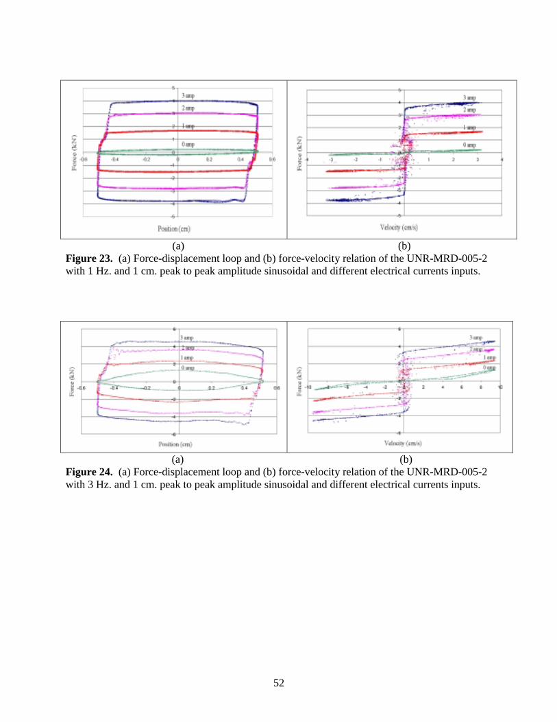
Figure 23. (a) Force-displacement loop and (b) force-velocity relation of the UNR-MRD-005-2 with 1 Hz. and 1 cm. peak to peak amplitude sinusoidal and different electrical currents inputs.
(a) (b) Figure 24. (a) Force-displacement loop and (b) force-velocity relation of the UNR-MRD-005-2 with 3 Hz. and 1 cm. peak to peak amplitude sinusoidal and different electrical currents inputs.
53
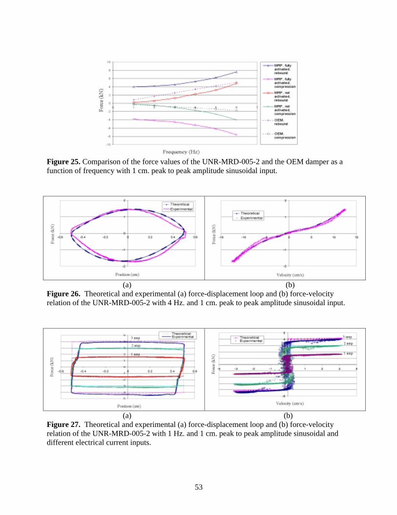
Figure 25. Comparison of the force values of the UNR-MRD-005-2 and the OEM damper as a function of frequency with 1 cm. peak to peak amplitude sinusoidal input.
(a) (b) Figure 26. Theoretical and experimental (a) force-displacement loop and (b) force-velocity relation of the UNR-MRD-005-2 with 4 Hz. and 1 cm. peak to peak amplitude sinusoidal input.
(a) (b) Figure 27. Theoretical and experimental (a) force-displacement loop and (b) force-velocity relation of the UNR-MRD-005-2 with 1 Hz. and 1 cm. peak to peak amplitude sinusoidal and different electrical current inputs.

54
Figure 28. Two degree-of-freedom quarter car model for semi-active HMMWV suspension system.
Figure 29. Passive damping representation of the skyhook control in quarter car model.
k1
k2
xr
x2
x1
ms
mu
c
xr
x1
x2
c
k1
k2
ms
mu
55
Figure 30. The experimental setup.
The ¼ of the mass of the vehicle under the suspension system
Suspension System including the shock absorber and compression spring
The springs representing the air pressure of the HMWWV tire
The mass of the ¼ vehicle with passengers
The input plate representing the excitation due to the road profile
Instron Hydraulic Actuator
Linear Slide System providing the movement of the masses

56
0
0.5
1
1.5
2
2.5
3
0 0.5 1 1.5 2 2.5 3 3.5 4 4.5 5 5.5 6 6.5 7 7.5 8Frequency (Hz)
Acc
eler
atio
n Tr
ansm
issi
bilit
yOEMpassive-offskyhook on-offcontinuous skyhook
0
0.5
1
1.5
2
2.5
3
0 0.5 1 1.5 2 2.5 3 3.5 4 4.5 5 5.5 6 6.5 7 7.5 8
Frequency (Hz)
Dis
plac
emen
t Tra
nsm
issi
bilit
y
OEM
passive-off
skyhook on-off
continuous skyhook
Figure 32. Displacement transmissibility experimental data for the sprung mass with 1 cm amplitude input.
Figure 31. Acceleration transmissibility experimental results of sprung mass for 1cm amplitude input.
57
0.000
0.001
0.002
0.003
0.004
0.005
0.006
0.007
0 1 2 3 4 5 6 7 8 9 10
Frequency (Hz)
Dis
plac
emen
t PSD
(cm2 /H
z)
Figure 33. PSD displacement random input.
0.E+00
1.E+06
2.E+06
3.E+06
4.E+06
5.E+06
6.E+06
7.E+06
8.E+06
9.E+06
1.E+07
0 1 2 3 4 5 6 7 8 9 10
Frequency (Hz)
Acc
eler
atio
n PS
D (c
m2 /s
4 /Hz)
OEMpassive-offskyhook on-offcontinuous skyhook
Figure 34. Experimental acceleration PSD of sprung mass under random excitation.
58
1
0.95
1.03
0.92
0.85
0.9
0.95
1
1.05
RMS
RM
S A
ccel
erat
ion
Figure 35. Experimental acceleration RMS of sprung mass under random excitation.
0
20
40
60
80
100
120
140
160
180
200
0 1 2 3 4 5 6 7 8
Frequency (Hz)
PSD
Dis
plac
emen
t (cm
2 /Hz)
OEMpassive-offskyhook on-offcontinuous skyhook
Figure 36. Experimental displacement data of sprung mass under random excitation.
1
0.95
0.87 0.86
0.75
0.8
0.85
0.9
0.95
1
1.05
RMS
RM
S D
ispl
acem
ent
Figure 37. Experimental displacement RMS results.
OEM
On-Off Skyhook
Passive-Off OEM Continuous
Skyhook
On-Off Skyhook
Passive- Off
OEM Continuous Skyhook