Embed Size (px)
Citation preview

Continuous Compression Stress Relaxation of Rubber Materials: Testing and Sil!lulation
Abraham Pannikottu, Charles Lu, Mark Centea
1. lntroduction
Akren Rubber Development Laboratory, lnc. 2887 Gilchrist Road, Akren, OH 44305
Rubber is extensively used as gasket and seal materials. The force applied during clamp-up is stored in the deformed rubber and exerts back pressure against the flanges maintaining a tight seal. This sealing force will decrease with stress relaxation. lt will also change with temperature variation and resultant expansion or contraction of the seal, and change as the rubber swells or shrinks in the fluid being sealed.
Stress relaxation is regarded as being the most convenient method of evaluating the suitability of a given rubber material for sealing applications (Zhang and Birley 1992, Bunting et al., 1992). However, the conventional test, particularly the short-term test, can be misleading, since in actual application the rubber will function over a wide temperature range between meta! flanges. The current continuous compression stress relaxation (CCSR) test aims to offer an improved method of evaluating rubber compounds. /
2. ARDL Continuous Compression Stress Relaxation Test
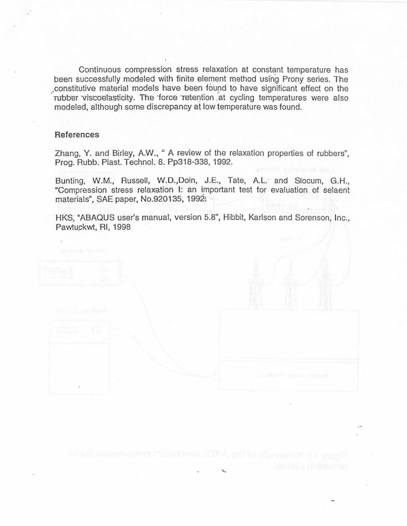
2.1 Apparatus The ARDL continuous compression stress relaxation (CCSR) apparatus is
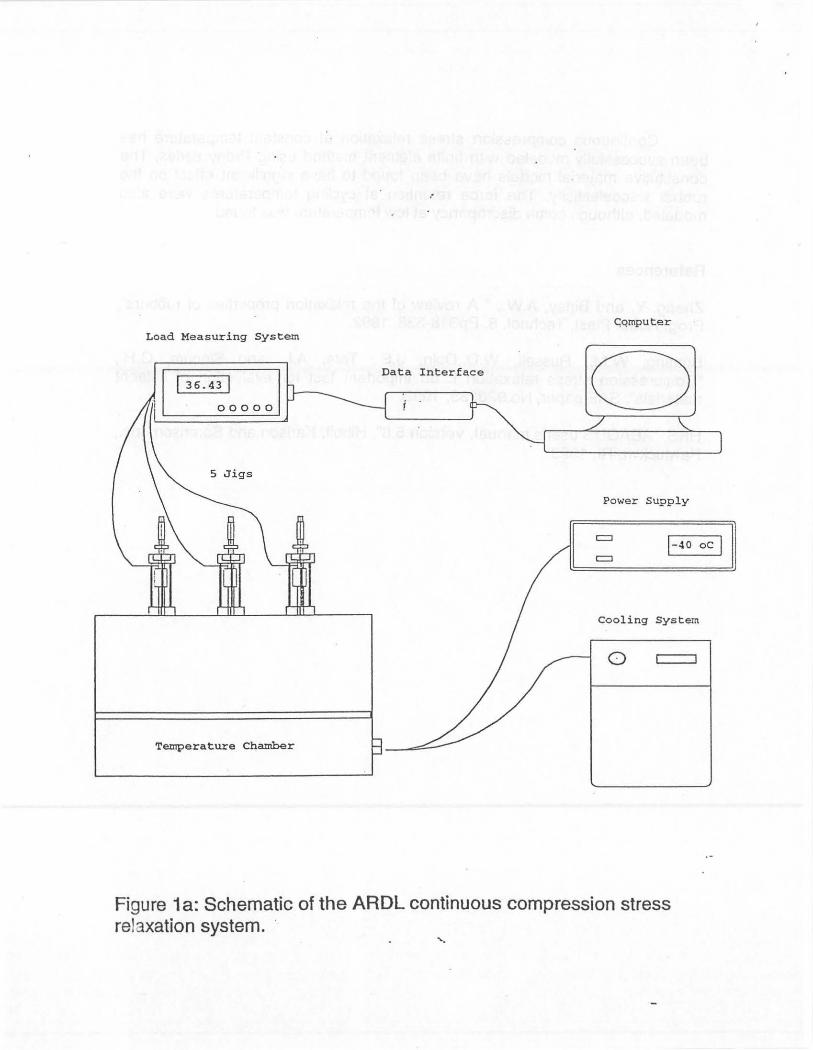
shown in Figure 1a and Figure 1b. The apparatus consists of 5 fixtures, sitting inside the temperature. chamber. ln each fixture, the specimen is placed betv-iaen the base plate and compression plate. The compression is set by a ·high-resolution screw adjuster with a lock nut, which maintains the compression · at the desired constant value. A Ioad cell is installed in series between the screw adjuster and the plunger, and connected to a multi-functional measuring
Presented at the 3rd International Symposiüm on Finite Element Analysis of Rubber and Rubber-Like Materials, May 19-20, The University of Akmn, Akren, OH, 1999.
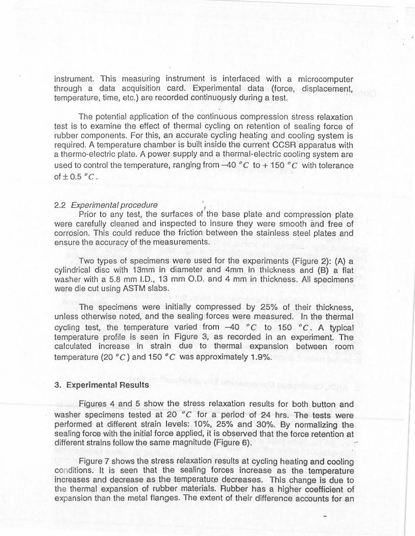
instrument. This measuring instrument is interfaced with a microcomputer through a data acquisition card. Experimental data (force, displacement, temperature, time, etc.) are recorded continuo.usly during a test.
The potential application of the continuous compression stress relaxation test is to examine the etfect of thermal cycling on retention of sealing force of rubber components. For this, an accurate cycling heating and cooling system is required. A temperature chamber is built inside the current CCSR apparatus with a thermo-electric plate. A power supply and a thermal-electric cool ing system are used to control the te.mperature, ranging from -40 ° C to + 150 o C with tolerance of ± 0.5 °C.
2.2 Experimental procedure 1 Prior to any test, the surfaces of the base plate and compression plate
were carefully cleaned and inspected to insure they were smooth and free of corrosion. This could reduce the friction between the stainless steel plates and ensure the accuracy of the measurements.
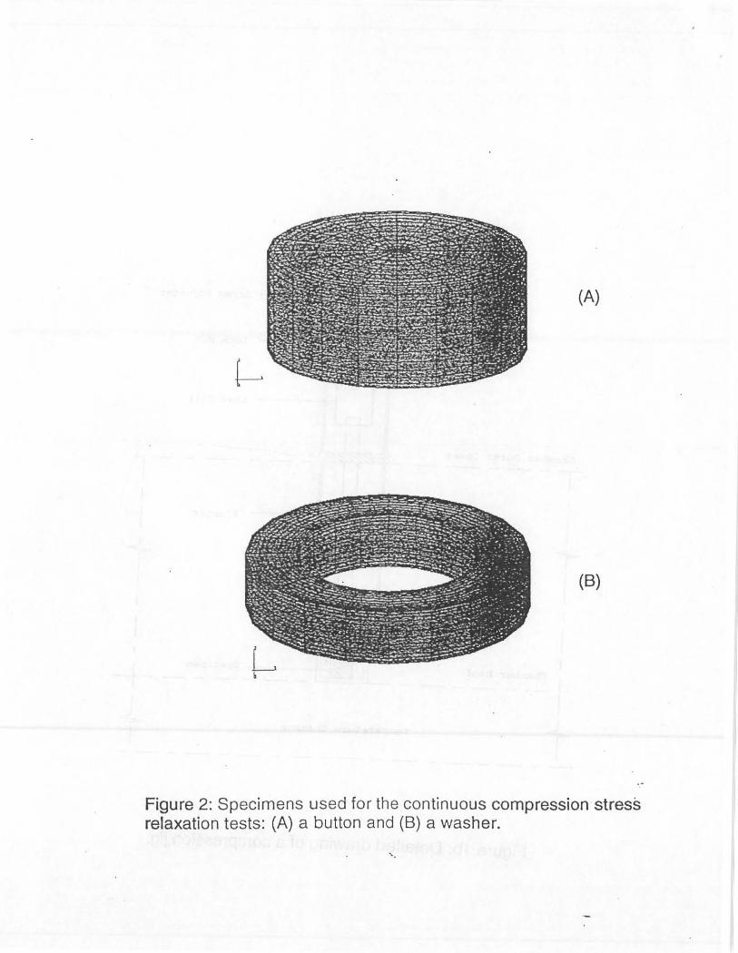
Two types of specimens were used for the experiments (Figure 2): (A) a cylindrical disc with 13mm in diameter and 4mm in thickness and (B) a flat washer with a 5.8 mm 1.0., 13 mm 0.0. and 4 mm in thickness. All specimens were die cut using ASTM slabs.
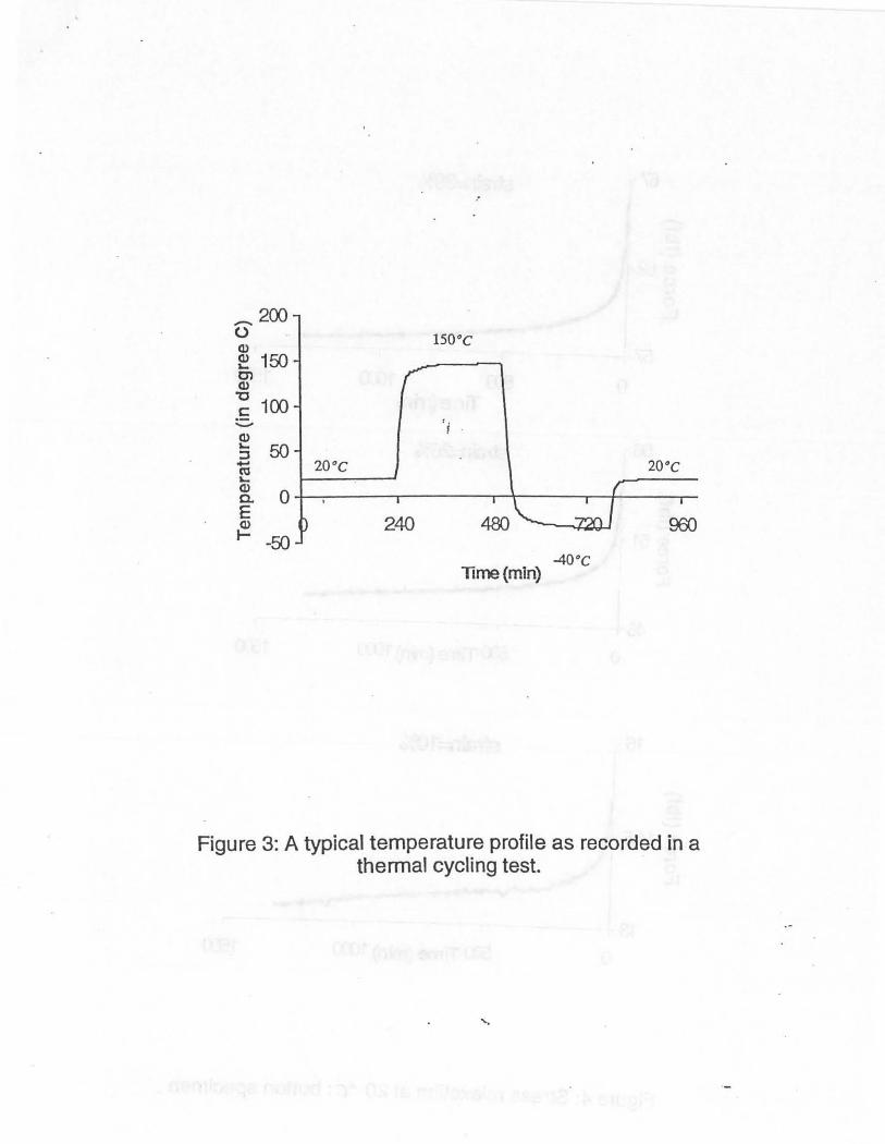
The specimens were initially compressed by 25% of their thickness, unless otherwise noted, and the sealing forces were measured. Jn the thermal cycling test, the temperature varied from -40 '' c to 150 '' c. A typical temperature profile is seen in Figure 3, as recorded in an experiment. The catculated increase in strain due to thermal expansion between room temperature (20 o C) and 150 o C was approximately 1.9%.
3. Experimental Results
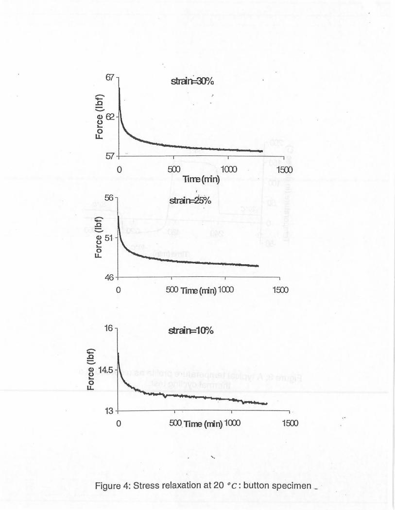
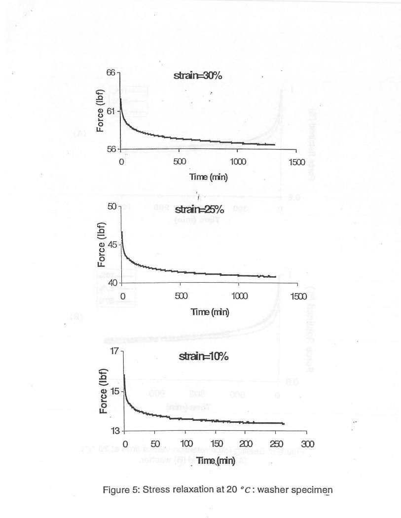
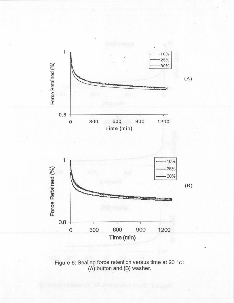
Figures 4 and 5 show the stress relaxation results for both button and washer specimens tested at 20 "C for a period of 24 hrs. The tests were performed at different strain Ievels: 10%, 25% and 30%. By normalizing the sealing force with the initial force applied, it is observed that the force retention at different strains fotlow the same magnitude (Figure 6).
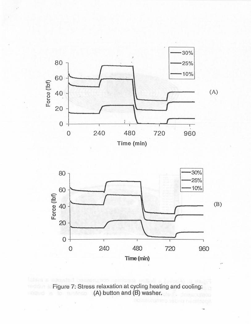
Figure 7 shows the stress retaxation results at cycling heating and cooling conditions. 1t is seen that the sealing forces increase as the temperature increases and decrease as the temperatur.e decreases. This change is due to the thermal expansion of rubber materials. Rubber has a higher coefficient of expansion than the meta! flanges. The extent of their difference accounts for an
I I
I 1
I I (
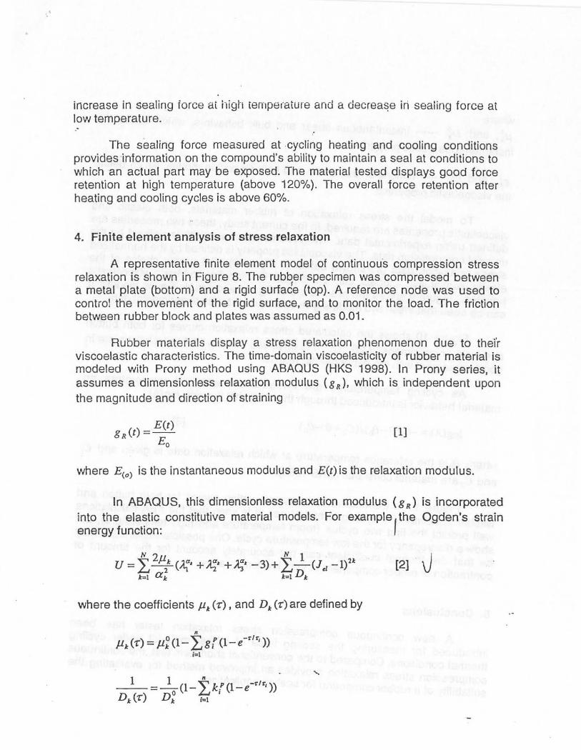
increase in sealing torce at high cemper"ature and a decrea~e iri seaiing force at low temperature . . ·
The sealing force measured at -cycling heating and cooling conditions provides ·information on the compound's ability to maintain a seal at conditions to which an actual part may be exposed. The material tested displays good force retention at high temperature (above 120%). The overall force retention after heating and cooling cycles is above 60%.
4. Finite element analysis of stress relaxation
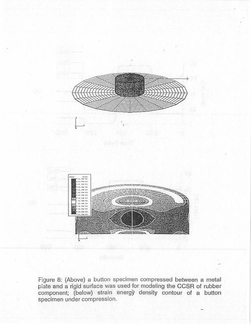
A representative finite element model of continuoüs compression stress relaxation is shown in Figure 8. The rubber specimen was compressed between a meta! plate (bottom) and a rigid surtade (top). A reference node was used to control the movement of the rigid surface, and to monitor the Ioad. The friction between rubber block and plates was assumed as 0.01.
Rubber materials display a stress relaxation phenomenon due to thei'r viscoelastic characteristics. The time-domain viscoelasticity of rubber material is modeled with Prony method using ABAOUS (HKS 1998). ln Prony series, it assumes a dimensionlass relaxation modulus (gR), which is independent upon the magnitude and direction of straining
() _ E(t)
gR t - - Eo
[1]
where E<o) is the instantaneous modulus and E(t) is the relaxation modulus.
ln ABAQUS, this dimensionless relaxation modulus ( g R) is incorporated into the elastic constitutive material models. For example f the Ogden's strain energy function:
[2] J
where the coefficients J11:. (r), and D~:. (r) are defined by
n
Jl~:.('r) = Jl~(l-L8{(1-e-rlr1)) i=l
where f.l.~, and D~ ------ instantaneous shear and bulk behaviors, which define the
·]nstantaneous elastic properties.
g{, and k: ------ dimensionlass shear and bulk relaxation moduli, which define
the viscoelastic properties
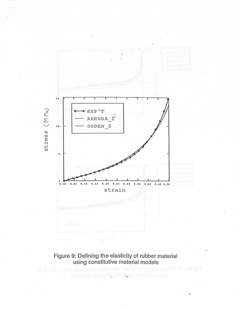
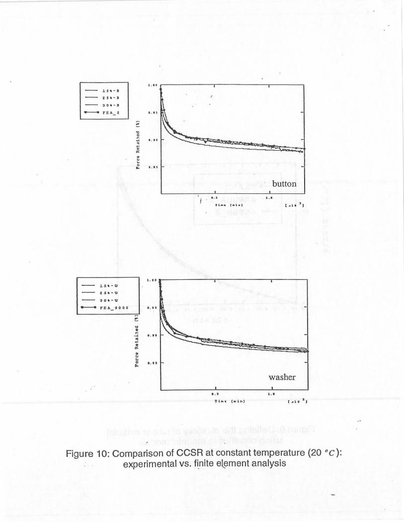
To model the stress relaxation of rubber materials, both elastic and viscoelastic properties are required. ln the current study, these two properties are defined using experimental data. The instantaneous elasticity is defined by the uniaxial compression data. The viscoelastic property is defined by the normalized stress relaxation data (as shown earlier in Figure 6). The proper choice of the elastic constitutive models can be critical in modeling rubber's viscoelastic behavior. Figure 9 shows the predictions 6f Ogden and Arruda-Boyce models. lt can be seen that these two models give accurate fits to the experimental data.
Figure 10 shows the calculated stre:ss relaxation curves for both button and washer specimens at 20 o C. lt is observed that the FEA calculations are in good agreement with the experimental resu~ts. ·
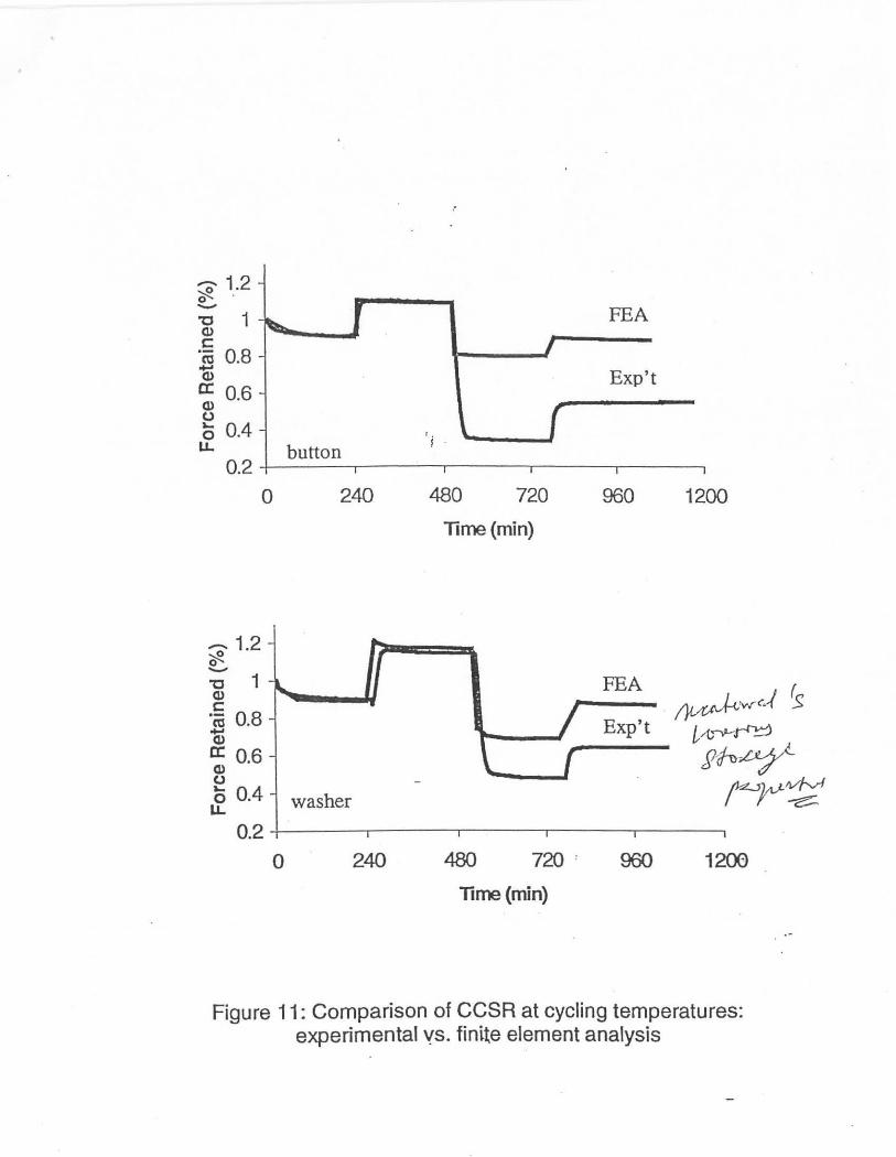
As cycling temperatures are involved, the effect of temperature on material behavior is introduced through the WLF shift function log(A)
[3]
where 80 is the reference temperature at which relaxation data is given and C1
and C2 arematerial constants (HKS 1998).
Figure 11 is the calculated stress relaxation curves for both button and washer specimens at cycling temperatures. lt is seen that the FEA calculations weil predict the first two cycles (room temperature and high temperature), but show a discrepancy for the low temperature cycle. One possible explanation may be that the thermal coefficient can not ~ccurately account for the amount of contraction of rubber component at very low temperature.
5. Conclusions
A new continuous compression stress relaxation tester has been introduced for measuring the sealing force of rubber material under cycling th :;rmal conditions. Compared to the conventional short-term test, the continuous compression stress relaxation provides an .. .jmproved method for evaluating the suitability of a rubber compound for sealing applications.
Continuous compression stress relaxation at constant temperature has been successfully modeled with finite element method usihg Prony series. The .constitutive material models have been fou[ld to have significant effect on the · rubbBT viscoetastictty. The ·force ·reter:ttion .'at cycling temperatures were also modeled, although some discrepancy at low temperature was found.
References
Zhang, Y. and Birley, A.W., " A review of the relaxation properties of rubbers", Prog. Rubb. Plast. Techno!. 8. Pp318-338, 1992.
Bunting, W.M., Russell, W.D.,Doin, J.E., Tate, A.L.· and Slocum, G.H., .. Compression stress relaxation 1: an i_mportant test for evaluation of selaent materials", SAE paper, No.920135, 1992t ·
HKS, "ABAQUS user's manual, version 5.8", Hibbit, Karlson and Sorenson, lnc., Pa~upk~. Rl, 1998
c;qrnputer Load Measuring System
I 36.43 I Data Interface
00000
5 Jigs
Power Supply
1-40 oC I
Cooling System
Temperature Chamher
Figure 1 a: Schematic of the ARDL continuous compression stress relaxation system. ·
Charnber Outer Cove r
T
I
T
i t
Chamber Roof
.·
Screw Adjuster
Lock Nut
Load Cell
- -~~2'4 - --------_ ·_-- ~\
Plunger I
t Specimen
t-Temperature Chamber + ------------------ ·
Figure 1b: Detailed drawing. of a compression jig.
(A)
(B)
Figure 2: Specimens used for the continuous compression stress relaxation tests: (A) a button and (B) a washer.
........ 200 0 150°C C1)
~ 150 0') C1)
~ 100 - '; C1) '- 50 :J -Cl:! '-
20 °C 20°C C1)
0 c. E
240 C1) ..... -50
Figure 3: A typical temperature profile as recorded in a thermal cycling test.
.....
01 strci~lo
-..... .c --G>62 0 '-0 LL
51
0 8JJ 1CID 19)) lirre(nin)
56 strci~/o
--.c --Cl> 5l 0 '-0
LL
46
0 flD lirre (nin) 1CXD 1flD
16 strcin=1 00/o
--.c --~ 14.5 '-0 LL
13
0 roJ.lirre (rrin) 1cro 1flD
Figure 4: Stress relaxation at 20 o c : button specimen _
00 straiJl=300/o
--.!l -(1.) 61 0 '-0 u.
56
0 EID 1ax> 1fffi
lirre (nin)
I . ff) strciJl::2lO/o
--.c -....._..
40 +---------~--------~------~
0 100)
lirre (rrin)
17 strain=1 Cf/o -:E -....._.. Cl)- 15 ,
~ 13 l-:~----.._ ............ ~ ·-· ............... ·-~ 0 ff) . 100
_ lirre,(nin)
Figu re 5: Stress relaxation at 20 o c: washer specim~
1 -10%
-25% ....... ~ --30% ........... "'0 <D .5 ctS ..... Cl> a: Cl> 0 '-0 u.
0.8 ' 0 300 600 900 1200
Time (min)
1 -10% - -25% ~ 0 -"0 -30% Q) c: ·-ca +-' Q)
a: Q) 0 :L.. 0
LL.
0.8 0 300 600 900 1200
· Time {min)
Figure 6: Sealing force retention versus time at 20 oc: (A) button and (B) washer. . .....
(A)
(B)
80 l E 25Yo
-10% 60 ..-... -.0 -Cl> 40
0 }.-
0 u.
20
0 0 240 480 720 960
Time (min)
I
-3Cf/ol 80l -25°/ol
I
60 I-1Cf/ol c;:' .c ::::::-(!.)40 0 }.-
0 u. 20
~ [ 0
r 0 240 480 720 960
Time(min)
Figura 7: Stress reiaxation at cycling heating and cooling: (A) button and (B) washer.
(A)
(B)
f .
Figure 8: (Above) a button specimen compressed between a metal plate and a rigid surface was used for modefing the CCSR of rubber component; (below) strain energy density contour of a button specimen under compression.
? lL
~ "-.,_/
U)
U) Q) 5-l +J U)
lL
1t--11 EX P 'T '·
ARRUDA 2'
10. OGDEN 2
!1 •
.. ~~~--~--~ __ ._ __ ._ __ ._ __ ._ __ ~--~~ a.aa a.as a.1a a . 1s a . ~• a . 1s a.la a.Js a.6a a.6s a . sa
strain
Figure 9: Defining the elasticity of rubbermaterial using constitutive material models
"·
1. •• ,..-------.-------...------.
~01-11
...._ TI:A_t a.u
.. u ... 0 ... I , I S
· button
... ...
l . •• ---------,---------.----....,
~o•-g
-- T:CA_liOOO a . IS
"d • r: ·~ • · II
OS .. ... lt: ... tJ ... :. ....
washer
... l . l
Figure 10: Comparison of CCSR at constant temperature (20 oc): experimental vs. fi_nite eLement analysis
'0' 1.2 ()' · -"C 1 Cl> c:
"Cö 0.8 (I) a: 0.6 Cl> 0 0 0.4 u.
FEA
Exp't
button i .
0.2 +-------.----.-----.----~-----.
0 240 480 720 960 1200
Time (min)
-1.2- .... cft. I -"C 1 ~ FEA
~·vrc.-/ fs <1> I c:
"Cö 0.8 Exp't ... i/(,~~ <1> a:: 0.6 \.. ( 2~~ <1> 0
r-'r~ 0 0.4 washer LL
0.2 I I I
0 240 480 720 : 960 1200
Tlme(min)
Figure 11: Comparison of CCSR at cycling temperatures: experimental ys. finite element analysis