Embed Size (px)
Citation preview
Infinity 26 Touch REU-AM2626WDLInfinity 26 REU-AM2626WDInfinity 20 REU-AM2024WDInfinity 16 REU-AM1620WDInfinity 12 REU-AM1220WDB26 REU-A2626WBB20 REU-A2024WBB16 REU-A1620WB
To Suit Water Heater Models
Operation & Installation Manual
ContinuousFlow WaterHeater
This appliance must be installed in accordance with:• Manufacturer’s Installation Instructions• Current AS/NZS 3000, AS/NZS 3500 & AS/NZS 5601• Local Regulations and Municipal Building
Codes including local OH&S requirements
This appliance must be installed, maintainedand removed by an Authorised Person.
For continued safety of this appliance it mustbe installed and maintained in accordance withthe manufacturer’s instructions.

Rinnai 2 HW_CF OIM
This page is intentionally blank
Rinnai 3 HW_CF OIM
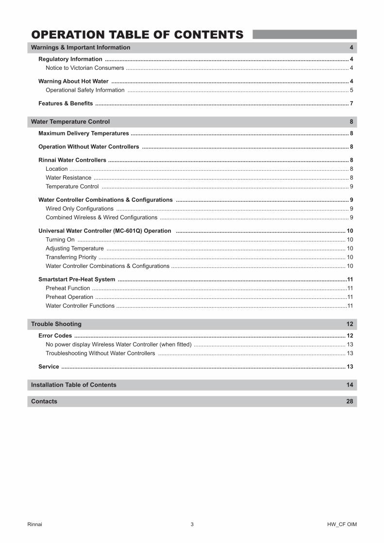
OPERATION TABLE OF CONTENTSWarnings & Important Information 4
Regulatory Information ������������������������������������������������������������������������������������������������������������������������������������������������������� 4Notice to Victorian Consumers ������������������������������������������������������������������������������������������������������������������������������������������ 4
Warning About Hot Water ��������������������������������������������������������������������������������������������������������������������������������������������������� 4Operational Safety Information ����������������������������������������������������������������������������������������������������������������������������������������� 5
Features & Benefits ������������������������������������������������������������������������������������������������������������������������������������������������������������� 7
Water Temperature Control 8
Maximum Delivery Temperatures ��������������������������������������������������������������������������������������������������������������������������������������� 8
Operation Without Water Controllers �������������������������������������������������������������������������������������������������������������������������������� 8
Rinnai Water Controllers ����������������������������������������������������������������������������������������������������������������������������������������������������� 8Location ����������������������������������������������������������������������������������������������������������������������������������������������������������������������������� 8Water Resistance �������������������������������������������������������������������������������������������������������������������������������������������������������������� 8Temperature Control ��������������������������������������������������������������������������������������������������������������������������������������������������������� 9
Water Controller Combinations & Configurations ����������������������������������������������������������������������������������������������������������� 9Wired Only Configurations ������������������������������������������������������������������������������������������������������������������������������������������������ 9Combined Wireless & Wired Configurations ��������������������������������������������������������������������������������������������������������������������� 9
Universal Water Controller (MC-601Q) Operation ��������������������������������������������������������������������������������������������������������� 10Turning On ���������������������������������������������������������������������������������������������������������������������������������������������������������������������� 10Adjusting Temperature ���������������������������������������������������������������������������������������������������������������������������������������������������� 10Transferring Priority ��������������������������������������������������������������������������������������������������������������������������������������������������������� 10Water Controller Combinations & Configurations ������������������������������������������������������������������������������������������������������������ 10
Smartstart Pre-Heat System ����������������������������������������������������������������������������������������������������������������������������������������������11Preheat Function ��������������������������������������������������������������������������������������������������������������������������������������������������������������11Preheat Operation ������������������������������������������������������������������������������������������������������������������������������������������������������������11Water Controller Functions �����������������������������������������������������������������������������������������������������������������������������������������������11
Trouble Shooting 12
Error Codes ������������������������������������������������������������������������������������������������������������������������������������������������������������������������ 12No power display Wireless Water Controller (when fitted) ���������������������������������������������������������������������������������������������� 13Troubleshooting Without Water Controllers �������������������������������������������������������������������������������������������������������������������� 13
Service �������������������������������������������������������������������������������������������������������������������������������������������������������������������������������� 13
Installation Table of Contents 14
Contacts 28
Rinnai 4 HW_CF OIM
REGULATORY INFORMATION
Your Rinnai Continuous Flow water heater has been certified by the Australian Gas Association. The A.G.A. Certification Number is shown on the data plate.
This Appliance must be installed correctly by an authorised person� The installation of gas, water, and electricity must conform to local regulations�
The installation must also comply with the instructions supplied by Rinnai�
All dimensions referred to in these instructions are in millimetres, unless otherwise specified.
Please keep this instruction booklet in a safe place for future reference�
Notice to Victorian Consumers
This appliance must be installed by a person licensed with the Plumbing Industry Commission�
Only a licensed person will have insurance protecting their workmanship�
So make sure you use a licensed person to install this appliance and ask for your Compliance Certificate. For Further information contact the Plumbing Industry Commission on 1300 815 127�
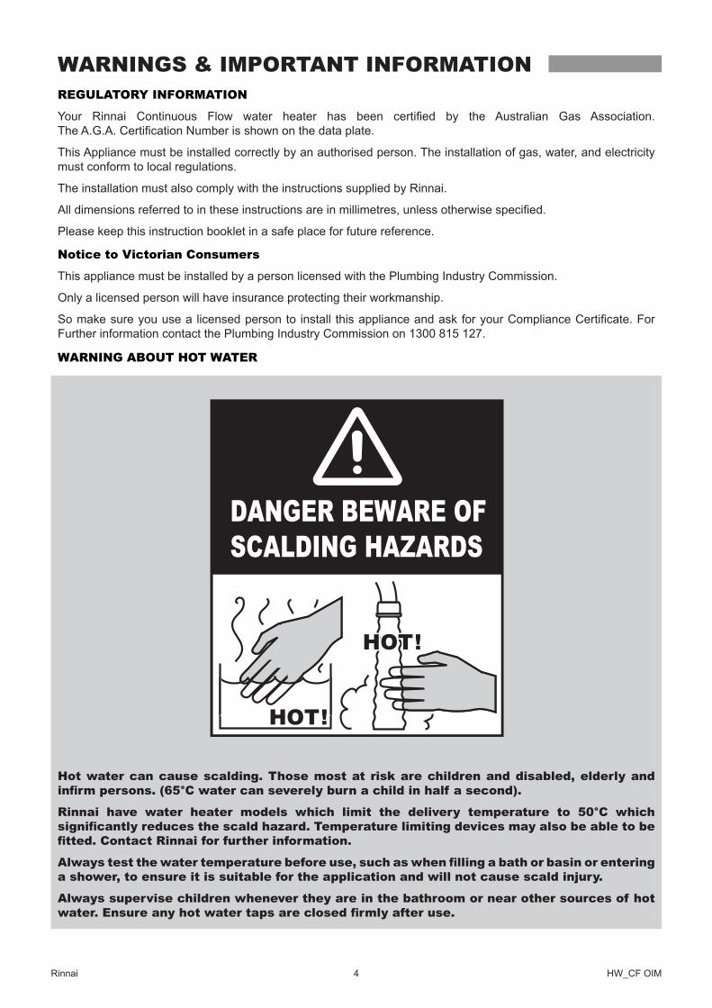
WARNING ABOUT HOT WATER
Hot water can cause scalding. Those most at risk are children and disabled, elderly and infirm persons. (65°C water can severely burn a child in half a second).
Rinnai have water heater models which limit the delivery temperature to 50°C which significantly reduces the scald hazard. Temperature limiting devices may also be able to be fitted. Contact Rinnai for further information.
Always test the water temperature before use, such as when filling a bath or basin or entering a shower, to ensure it is suitable for the application and will not cause scald injury.
Always supervise children whenever they are in the bathroom or near other sources of hot water. Ensure any hot water taps are closed firmly after use.
WARNINGS & IMPORTANT INFORMATION
Rinnai 5 HW_CF OIM
Operational Safety Information
IMPORTANT
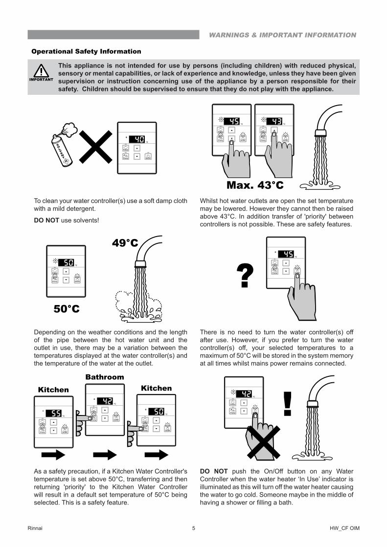
This appliance is not intended for use by persons (including children) with reduced physical, sensory or mental capabilities, or lack of experience and knowledge, unless they have been given supervision or instruction concerning use of the appliance by a person responsible for their safety� Children should be supervised to ensure that they do not play with the appliance�
To clean your water controller(s) use a soft damp cloth with a mild detergent�
DO NOT use solvents!
Whilst hot water outlets are open the set temperature may be lowered� However they cannot then be raised above 43°C� In addition transfer of 'priority' between controllers is not possible� These are safety features�
Depending on the weather conditions and the length of the pipe between the hot water unit and the outlet in use, there may be a variation between the temperatures displayed at the water controller(s) and the temperature of the water at the outlet�
There is no need to turn the water controller(s) off after use� However, if you prefer to turn the water controller(s) off, your selected temperatures to a maximum of 50°C will be stored in the system memory at all times whilst mains power remains connected�
As a safety precaution, if a Kitchen Water Controller's temperature is set above 50°C, transferring and then returning 'priority' to the Kitchen Water Controller will result in a default set temperature of 50°C being selected� This is a safety feature�
DO NOT push the On/Off button on any Water Controller when the water heater ‘In Use’ indicator is illuminated as this will turn off the water heater causing the water to go cold� Someone maybe in the middle of having a shower or filling a bath.
SOLVENT
WARNINGS & IMPORTANT INFORMATION
Rinnai 6 HW_CF OIM
IMPORTANT
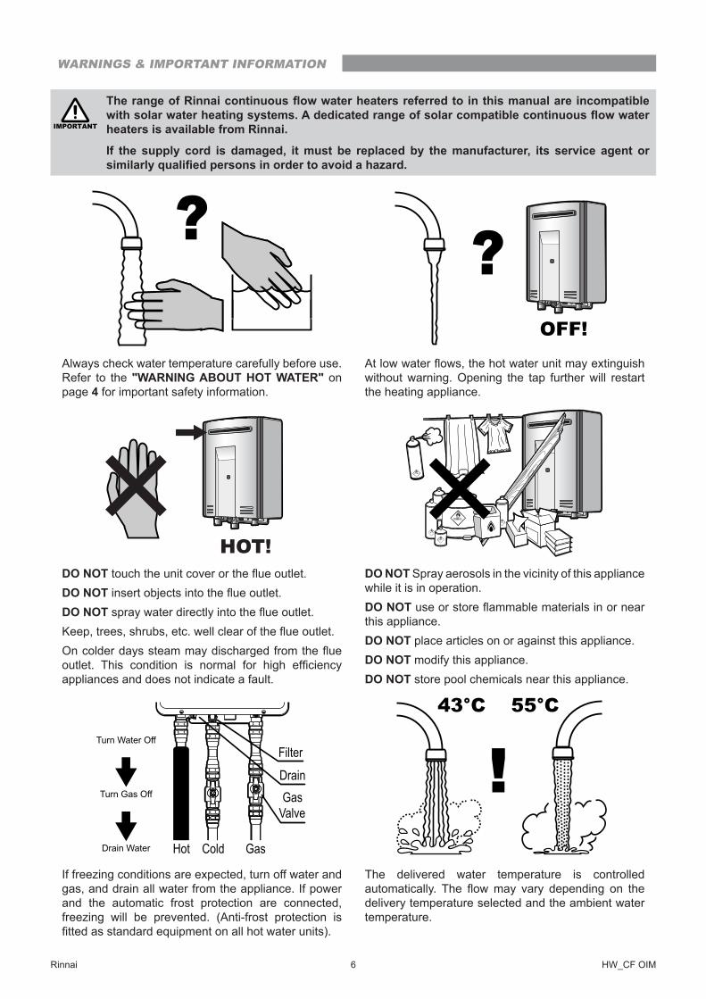
The range of Rinnai continuous flow water heaters referred to in this manual are incompatible with solar water heating systems. A dedicated range of solar compatible continuous flow water heaters is available from Rinnai�
If the supply cord is damaged, it must be replaced by the manufacturer, its service agent or similarly qualified persons in order to avoid a hazard.
Always check water temperature carefully before use� Refer to the "WARNING ABOUT HOT WATER" on page 4 for important safety information�
At low water flows, the hot water unit may extinguish without warning� Opening the tap further will restart the heating appliance�
DO NOT touch the unit cover or the flue outlet.DO NOT insert objects into the flue outlet.DO NOT spray water directly into the flue outlet.Keep, trees, shrubs, etc. well clear of the flue outlet.On colder days steam may discharged from the flue outlet. This condition is normal for high efficiency appliances and does not indicate a fault�
DO NOT Spray aerosols in the vicinity of this appliance while it is in operation�DO NOT use or store flammable materials in or near this appliance�DO NOT place articles on or against this appliance�DO NOT modify this appliance�DO NOT store pool chemicals near this appliance�
If freezing conditions are expected, turn off water and gas, and drain all water from the appliance� If power and the automatic frost protection are connected, freezing will be prevented� (Anti-frost protection is fitted as standard equipment on all hot water units).
The delivered water temperature is controlled automatically. The flow may vary depending on the delivery temperature selected and the ambient water temperature�
OFF!
HOT!
43°C 55°C
WARNINGS & IMPORTANT INFORMATION
Rinnai 7 HW_CF OIM
FEATURES & BENEFITS
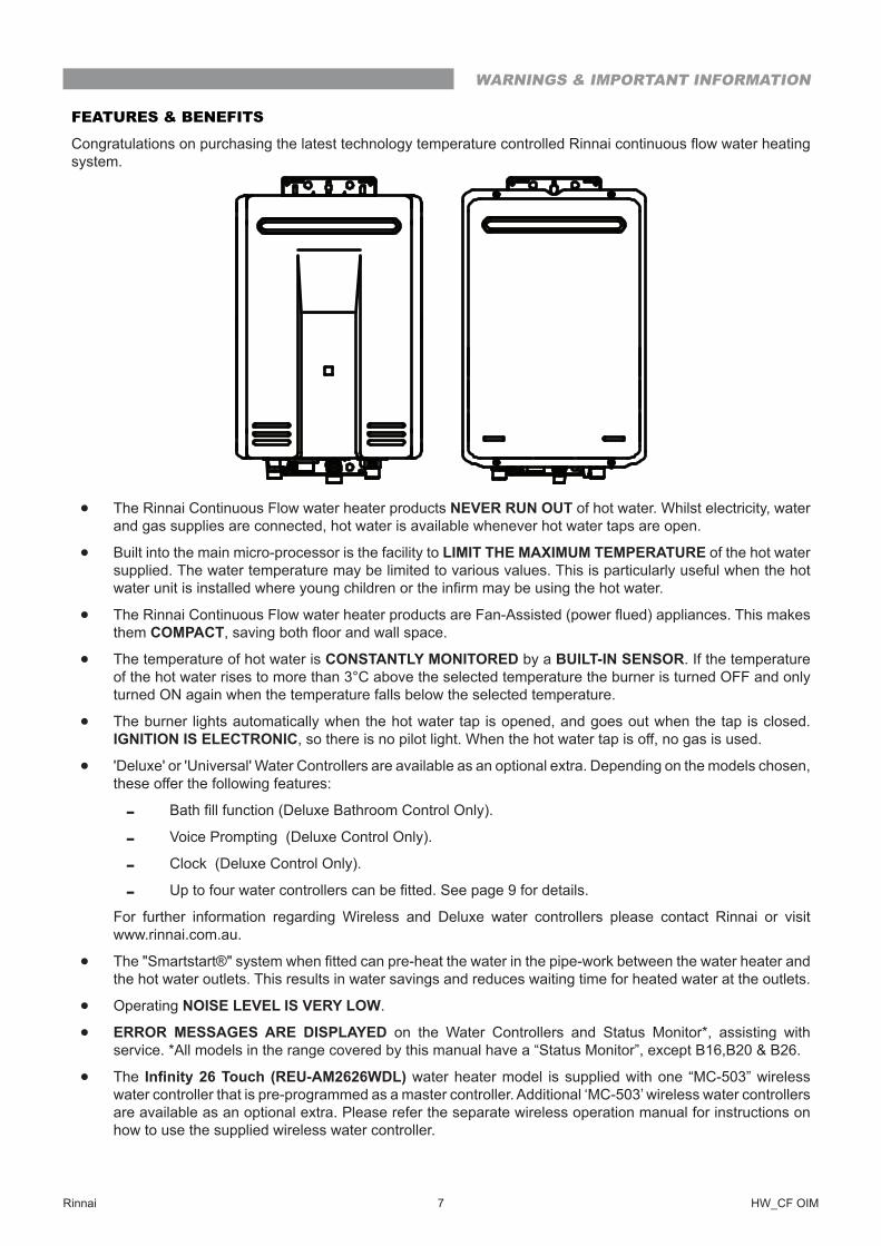
Congratulations on purchasing the latest technology temperature controlled Rinnai continuous flow water heating system�
• The Rinnai Continuous Flow water heater products NEVER RUN OUT of hot water� Whilst electricity, water and gas supplies are connected, hot water is available whenever hot water taps are open�
• Built into the main micro-processor is the facility to LIMIT THE MAXIMUM TEMPERATURE of the hot water supplied� The water temperature may be limited to various values� This is particularly useful when the hot water unit is installed where young children or the infirm may be using the hot water.
• The Rinnai Continuous Flow water heater products are Fan-Assisted (power flued) appliances. This makes them COMPACT, saving both floor and wall space.
• The temperature of hot water is CONSTANTLY MONITORED by a BUILT-IN SENSOR� If the temperature of the hot water rises to more than 3°C above the selected temperature the burner is turned OFF and only turned ON again when the temperature falls below the selected temperature�
• The burner lights automatically when the hot water tap is opened, and goes out when the tap is closed� IGNITION IS ELECTRONIC, so there is no pilot light� When the hot water tap is off, no gas is used�
• 'Deluxe' or 'Universal' Water Controllers are available as an optional extra� Depending on the models chosen, these offer the following features:
- Bath fill function (Deluxe Bathroom Control Only).
- Voice Prompting (Deluxe Control Only).
- Clock (Deluxe Control Only).
- Up to four water controllers can be fitted. See page 9 for details.
� For further information regarding Wireless and Deluxe water controllers please contact Rinnai or visit www�rinnai�com�au�
• The "Smartstart®" system when fitted can pre-heat the water in the pipe-work between the water heater and the hot water outlets� This results in water savings and reduces waiting time for heated water at the outlets�
• Operating NOISE LEVEL IS VERY LOW�
• ERROR MESSAGES ARE DISPLAYED on the Water Controllers and Status Monitor*, assisting with service� *All models in the range covered by this manual have a “Status Monitor”, except B16,B20 & B26�
• The Infinity 26 Touch (REU-AM2626WDL) water heater model is supplied with one “MC-503” wireless water controller that is pre-programmed as a master controller� Additional ‘MC-503’ wireless water controllers are available as an optional extra� Please refer the separate wireless operation manual for instructions on how to use the supplied wireless water controller�
WARNINGS & IMPORTANT INFORMATION
Rinnai 8 HW_CF OIM
MAXIMUM DELIVERY TEMPERATURES
Rinnai continuous flow water heaters are factory pre-set to various maximum delivery temperatures depending on model and their intended application� For the majority of applications, the factory pre-set temperature is appropriate�
In the unlikely event this is not the case this setting can be increased or decreased by an authorised person such as a licensed plumber�
NOTE
This does not apply to “50 degree compliant” models� To meet the regulatory requirements the maximum delivery temperature is factory set and sealed�
For model specific information in regards to the factory pre-set temperature of your appliance refer to "Table 3� Maximum Delivery Temperatures" on page 27� The appliance model number can be found on the dataplate, which is located on the left hand side of appliance�
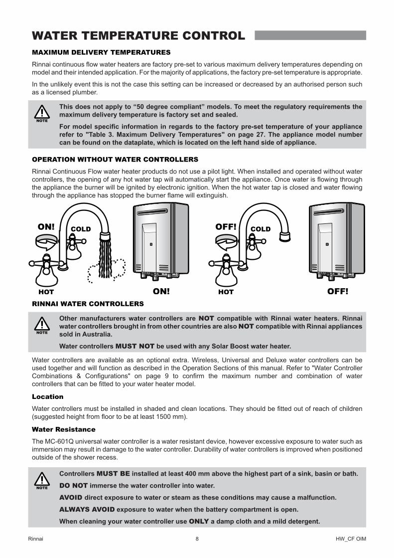
OPERATION WITHOUT WATER CONTROLLERS
Rinnai Continuous Flow water heater products do not use a pilot light� When installed and operated without water controllers, the opening of any hot water tap will automatically start the appliance. Once water is flowing through the appliance the burner will be ignited by electronic ignition. When the hot water tap is closed and water flowing through the appliance has stopped the burner flame will extinguish.
RINNAI WATER CONTROLLERS
NOTE
Other manufacturers water controllers are NOT compatible with Rinnai water heaters� Rinnai water controllers brought in from other countries are also NOT compatible with Rinnai appliances sold in Australia�
Water controllers MUST NOT be used with any Solar Boost water heater�
Water controllers are available as an optional extra� Wireless, Universal and Deluxe water controllers can be used together and will function as described in the Operation Sections of this manual� Refer to "Water Controller Combinations & Configurations" on page 9 to confirm the maximum number and combination of water controllers that can be fitted to your water heater model.
Location
Water controllers must be installed in shaded and clean locations. They should be fitted out of reach of children (suggested height from floor to be at least 1500 mm).
Water Resistance
The MC-601Q universal water controller is a water resistant device, however excessive exposure to water such as immersion may result in damage to the water controller� Durability of water controllers is improved when positioned outside of the shower recess�
NOTE
Controllers MUST BE installed at least 400 mm above the highest part of a sink, basin or bath�
DO NOT immerse the water controller into water�
AVOID direct exposure to water or steam as these conditions may cause a malfunction�
ALWAYS AVOID exposure to water when the battery compartment is open�
When cleaning your water controller use ONLY a damp cloth and a mild detergent�
WATER TEMPERATURE CONTROL
Rinnai 9 HW_CF OIM
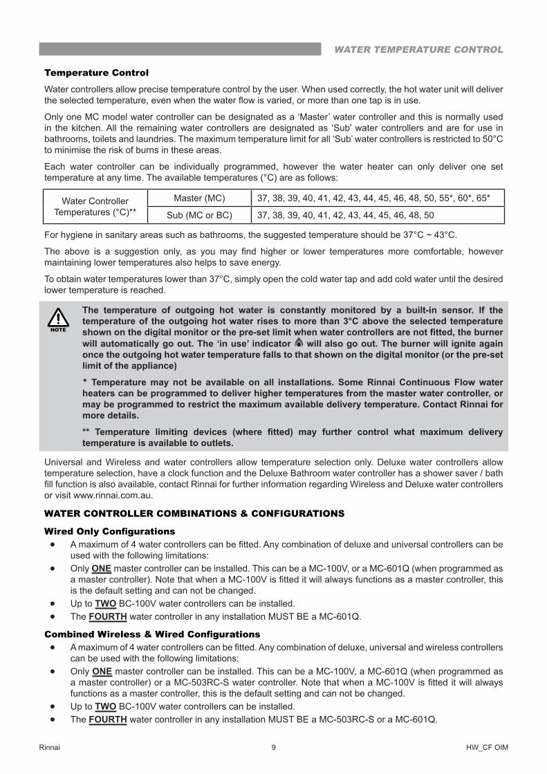
Temperature Control
Water controllers allow precise temperature control by the user� When used correctly, the hot water unit will deliver the selected temperature, even when the water flow is varied, or more than one tap is in use.
Only one MC model water controller can be designated as a ‘Master’ water controller and this is normally used in the kitchen� All the remaining water controllers are designated as ‘Sub’ water controllers and are for use in bathrooms, toilets and laundries� The maximum temperature limit for all ‘Sub’ water controllers is restricted to 50°C to minimise the risk of burns in these areas�
Each water controller can be individually programmed, however the water heater can only deliver one set temperature at any time. The available temperatures (°C) are as follows:
Water Controller Temperatures (°C)**
Master (MC) 37, 38, 39, 40, 41, 42, 43, 44, 45, 46, 48, 50, 55*, 60*, 65*
Sub (MC or BC) 37, 38, 39, 40, 41, 42, 43, 44, 45, 46, 48, 50
For hygiene in sanitary areas such as bathrooms, the suggested temperature should be 37°C ~ 43°C�
The above is a suggestion only, as you may find higher or lower temperatures more comfortable, however maintaining lower temperatures also helps to save energy�
To obtain water temperatures lower than 37°C, simply open the cold water tap and add cold water until the desired lower temperature is reached�
NOTE
The temperature of outgoing hot water is constantly monitored by a built-in sensor� If the temperature of the outgoing hot water rises to more than 3°C above the selected temperature shown on the digital monitor or the pre-set limit when water controllers are not fitted, the burner will automatically go out� The ‘in use’ indicator will also go out� The burner will ignite again once the outgoing hot water temperature falls to that shown on the digital monitor (or the pre-set limit of the appliance)
* Temperature may not be available on all installations� Some Rinnai Continuous Flow water heaters can be programmed to deliver higher temperatures from the master water controller, or may be programmed to restrict the maximum available delivery temperature� Contact Rinnai for more details�
** Temperature limiting devices (where fitted) may further control what maximum delivery temperature is available to outlets�
Universal and Wireless and water controllers allow temperature selection only� Deluxe water controllers allow temperature selection, have a clock function and the Deluxe Bathroom water controller has a shower saver / bath fill function is also available, contact Rinnai for further information regarding Wireless and Deluxe water controllers or visit www�rinnai�com�au�
WATER CONTROLLER COMBINATIONS & CONFIGURATIONS
Wired Only Configurations• A maximum of 4 water controllers can be fitted. Any combination of deluxe and universal controllers can be
used with the following limitations:
• Only ONE master controller can be installed� This can be a MC-100V, or a MC-601Q (when programmed as a master controller). Note that when a MC-100V is fitted it will always functions as a master controller, this is the default setting and can not be changed�
• Up to TWO BC-100V water controllers can be installed�
• The FOURTH water controller in any installation MUST BE a MC-601Q�
Combined Wireless & Wired Configurations• A maximum of 4 water controllers can be fitted. Any combination of deluxe, universal and wireless controllers
can be used with the following limitations:
• Only ONE master controller can be installed� This can be a MC-100V, a MC-601Q (when programmed as a master controller) or a MC-503RC-S water controller. Note that when a MC-100V is fitted it will always functions as a master controller, this is the default setting and can not be changed�
• Up to TWO BC-100V water controllers can be installed�
• The FOURTH water controller in any installation MUST BE a MC-503RC-S or a MC-601Q�
WATER TEMPERATURE CONTROL
Rinnai 10 HW_CF OIM
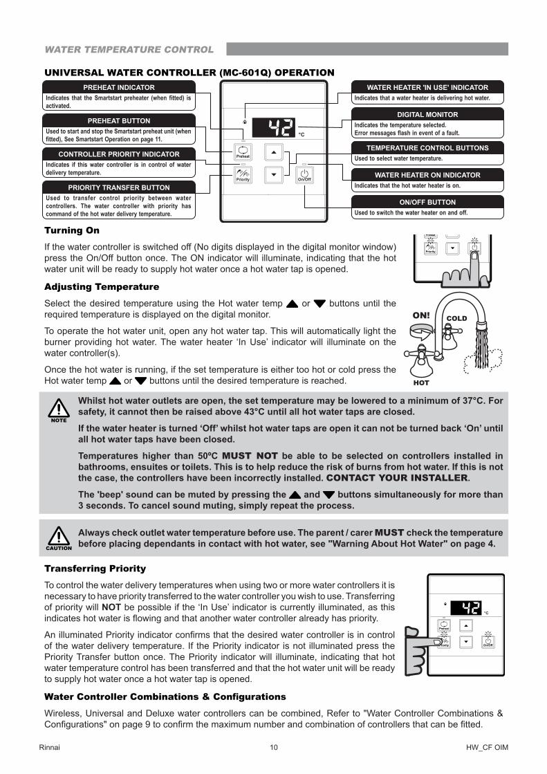
UNIVERSAL WATER CONTROLLER (MC-601Q) OPERATION
Turning On
If the water controller is switched off (No digits displayed in the digital monitor window) press the On/Off button once� The ON indicator will illuminate, indicating that the hot water unit will be ready to supply hot water once a hot water tap is opened�
Adjusting Temperature
Select the desired temperature using the Hot water temp or buttons until the required temperature is displayed on the digital monitor.
To operate the hot water unit, open any hot water tap� This will automatically light the burner providing hot water� The water heater ‘In Use’ indicator will illuminate on the water controller(s).
Once the hot water is running, if the set temperature is either too hot or cold press the Hot water temp or buttons until the desired temperature is reached�
NOTE
Whilst hot water outlets are open, the set temperature may be lowered to a minimum of 37°C� For safety, it cannot then be raised above 43°C until all hot water taps are closed�
If the water heater is turned ‘Off’ whilst hot water taps are open it can not be turned back ‘On’ until all hot water taps have been closed�
Temperatures higher than 50ºC MUST NOT be able to be selected on controllers installed in bathrooms, ensuites or toilets� This is to help reduce the risk of burns from hot water� If this is not the case, the controllers have been incorrectly installed� CONTACT YOUR INSTALLER�
The 'beep' sound can be muted by pressing the and buttons simultaneously for more than 3 seconds� To cancel sound muting, simply repeat the process�
CAUTION
Always check outlet water temperature before use� The parent / carer MUST check the temperature before placing dependants in contact with hot water, see "Warning About Hot Water" on page 4�
Transferring Priority
To control the water delivery temperatures when using two or more water controllers it is necessary to have priority transferred to the water controller you wish to use� Transferring of priority will NOT be possible if the ‘In Use’ indicator is currently illuminated, as this indicates hot water is flowing and that another water controller already has priority.
An illuminated Priority indicator confirms that the desired water controller is in control of the water delivery temperature� If the Priority indicator is not illuminated press the Priority Transfer button once� The Priority indicator will illuminate, indicating that hot water temperature control has been transferred and that the hot water unit will be ready to supply hot water once a hot water tap is opened�
Water Controller Combinations & Configurations
Wireless, Universal and Deluxe water controllers can be combined, Refer to "Water Controller Combinations & Configurations" on page 9 to confirm the maximum number and combination of controllers that can be fitted.
Indicates the temperature selected.Error messages flash in event of a fault.
DIGITAL MONITOR
Used to select water temperature.TEMPERATURE CONTROL BUTTONS
Indicates that the hot water heater is on.WATER HEATER ON INDICATOR
Used to switch the water heater on and off.ON/OFF BUTTON
Indicates that the Smartstart preheater (when fitted) is activated.
PREHEAT INDICATOR
Used to start and stop the Smartstart preheat unit (when fitted), See Smartstart Operation on page 11.
PREHEAT BUTTON
Indicates if this water controller is in control of water delivery temperature.
CONTROLLER PRIORITY INDICATOR
Used to transfer control priority between water controllers. The water controller with priority has command of the hot water delivery temperature.
PRIORITY TRANSFER BUTTON
Indicates that a water heater is delivering hot water.WATER HEATER 'IN USE' INDICATOR
HOTHOT
COLDCOLDON!ON!
WATER TEMPERATURE CONTROL
Rinnai 11 HW_CF OIM
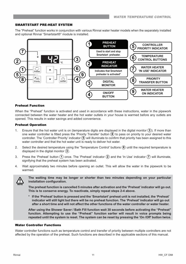
SMARTSTART PRE-HEAT SYSTEM
The “Preheat” function works in conjunction with various Rinnai water heater models when the separately installed and optional Rinnai “Smartstart®” module is installed�
Preheat Function
When the “Preheat” function is activated and used in accordance with these instructions, water in the pipework connected between the water heater and the hot water outlets in your house is warmed before any outlets are opened� This results in water savings and added convenience�
Preheat Operation
1� Ensure that the hot water unit is on (temperature digits are displayed in the digital monitor 3 ). If more than one water controller is fitted press the ‘Priority Transfer’ button 8 to pass on priority to your desired water controller� The ‘Controller Priority’ indicator 5 will illuminate to confirm that priority has been assigned to this water controller and that the hot water unit is ready to deliver hot water�
2� Select the desired temperature using the 'Temperature Control' buttons 6 until the required temperature is displayed in the digital monitor 3 �
3� Press the ‘Preheat’ button 1 once� The ‘Preheat’ indicator 2 and the ‘In Use’ indicator 7 will illuminate, signifying that the preheat system has been activated�
4� Wait approximately two minutes before opening an outlet� This will allow the water in the pipework to be warmed�
NOTE
The waiting time may be longer or shorter than two minutes depending on your particular installation configuration.
The preheat function is cancelled 5 minutes after activation and the ‘Preheat’ indicator will go out� This is to conserve energy� To reactivate, simply repeat steps 2-4 above�
* If the ‘Preheat’ button is pressed and the ‘Smartstart’ preheat unit is not installed, the ‘Preheat’ indicator will still light but there will be no preheat function� The ‘Preheat’ indicator will go out after a short time and will not affect the other functions of the water controller or water heater�
After using the Shower Saver / Bath Fill function wait 30 seconds before activating the “Preheat” function� Attempting to use the “Preheat” function earlier will result in voice prompts being repeated until the system is reset� The system can be reset by pressing the ‘On /Off' button twice�
Water Controller Functions
Water controller functions such as temperature control and transfer of priority between multiple controllers are not affected by the operation of the preheat� Such functions are described in the applicable sections of this manual�
2
7
1
85
3
6 Indicates that Smartstart preheater is activated*
PREHEATINDICATOR2
DIGITALMONITOR3
ON/OFFBUTTON4
CONTROLLERPRIORITY INDICATOR5
TEMPERATURECONTROL BUTTONS6
WATER HEATER'IN USE' INDICATOR7
PRIORITYTRANSFER BUTTON8
WATER HEATERON INDICATOR9
Used to start and stop Smartstart preheater.
PREHEATBUTTON1
49
WATER TEMPERATURE CONTROL
Rinnai 12 HW_CF OIM
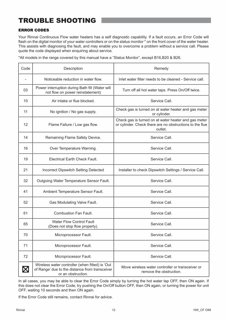
ERROR CODES
Your Rinnai Continuous Flow water heaters has a self diagnostic capability� If a fault occurs, an Error Code will flash on the digital monitor of your water controllers or on the status monitor * on the front cover of the water heater. This assists with diagnosing the fault, and may enable you to overcome a problem without a service call� Please quote the code displayed when enquiring about service.
*All models in the range covered by this manual have a “Status Monitor”, except B16,B20 & B26�
Code Description Remedy
- Noticeable reduction in water flow. Inlet water filter needs to be cleaned - Service call.
03 Power interruption during Bath fill (Water will not flow on power reinstatement) Turn off all hot water taps� Press On/Off twice�
10 Air intake or flue blocked. Service Call�
11 No ignition / No gas supply� Check gas is turned on at water heater and gas meter or cylinder�
12 Flame Failure / Low gas flow.Check gas is turned on at water heater and gas meter or cylinder. Check there are no obstructions to the flue
outlet�
14 Remaining Flame Safety Device� Service Call�
16 Over Temperature Warning� Service Call�
19 Electrical Earth Check Fault� Service Call�
21 Incorrect Dipswitch Setting Detected Installer to check Dipswitch Settings / Service Call�
32 Outgoing Water Temperature Sensor Fault� Service Call�
41 Ambient Temperature Sensor Fault� Service Call�
52 Gas Modulating Valve Fault. Service Call�
61 Combustion Fan Fault� Service Call�
65 Water Flow Control Fault (Does not stop flow properly). Service Call�
70 Microprocessor Fault� Service Call�
71 Microprocessor Fault� Service Call�
72 Microprocessor Fault� Service Call�
Wireless water controller (when fitted) is ‘Out of Range’ due to the distance from transceiver
or an obstruction�
Move wireless water controller or transceiver or remove the obstruction�
In all cases, you may be able to clear the Error Code simply by turning the hot water tap OFF, then ON again� If this does not clear the Error Code, try pushing the On/Off button OFF, then ON again, or turning the power for unit OFF, waiting 10 seconds and then ON again�
If the Error Code still remains, contact Rinnai for advice�
TROUBLE SHOOTING
Rinnai 13 HW_CF OIM
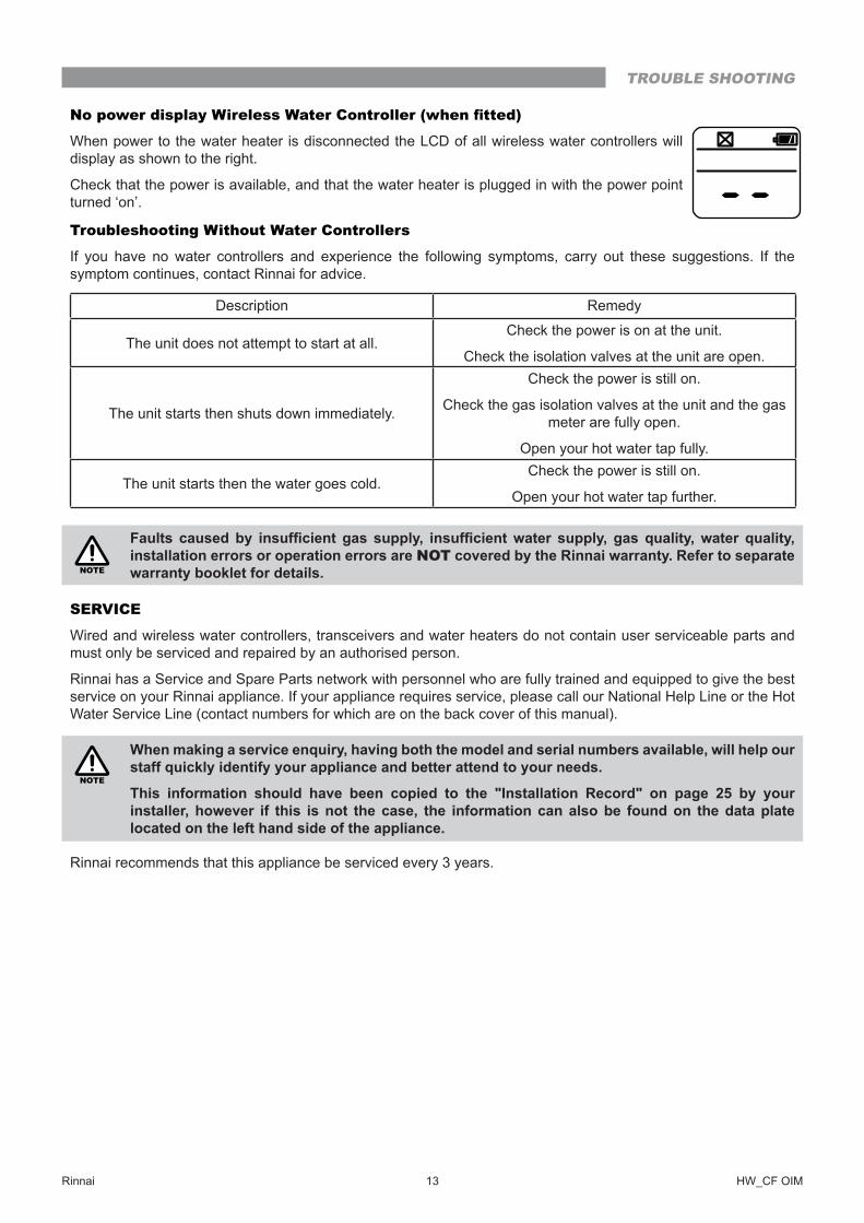
No power display Wireless Water Controller (when fitted)
When power to the water heater is disconnected the LCD of all wireless water controllers will display as shown to the right�
Check that the power is available, and that the water heater is plugged in with the power point turned ‘on’�
Troubleshooting Without Water Controllers
If you have no water controllers and experience the following symptoms, carry out these suggestions� If the symptom continues, contact Rinnai for advice�
Description Remedy
The unit does not attempt to start at all�Check the power is on at the unit�
Check the isolation valves at the unit are open�
The unit starts then shuts down immediately�
Check the power is still on�
Check the gas isolation valves at the unit and the gas meter are fully open�
Open your hot water tap fully�
The unit starts then the water goes cold�Check the power is still on�
Open your hot water tap further�
NOTE
Faults caused by insufficient gas supply, insufficient water supply, gas quality, water quality, installation errors or operation errors are NOT covered by the Rinnai warranty� Refer to separate warranty booklet for details�
SERVICE
Wired and wireless water controllers, transceivers and water heaters do not contain user serviceable parts and must only be serviced and repaired by an authorised person�
Rinnai has a Service and Spare Parts network with personnel who are fully trained and equipped to give the best service on your Rinnai appliance. If your appliance requires service, please call our National Help Line or the Hot Water Service Line (contact numbers for which are on the back cover of this manual).
NOTE
When making a service enquiry, having both the model and serial numbers available, will help our staff quickly identify your appliance and better attend to your needs�
This information should have been copied to the "Installation Record" on page 25 by your installer, however if this is not the case, the information can also be found on the data plate located on the left hand side of the appliance�
Rinnai recommends that this appliance be serviced every 3 years�
TROUBLE SHOOTING
Rinnai 14 HW_CF OIM
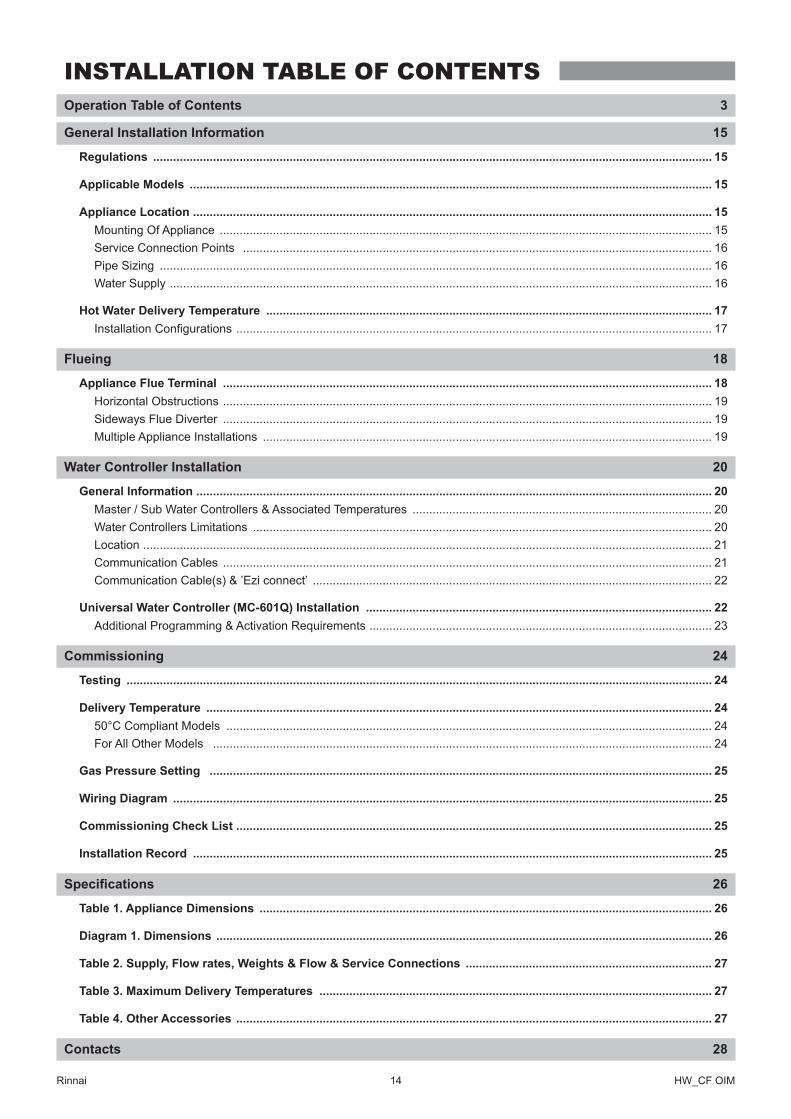
Operation Table of Contents 3
General Installation Information 15
Regulations ������������������������������������������������������������������������������������������������������������������������������������������������������������������������ 15
Applicable Models ������������������������������������������������������������������������������������������������������������������������������������������������������������� 15
Appliance Location ������������������������������������������������������������������������������������������������������������������������������������������������������������ 15Mounting Of Appliance ���������������������������������������������������������������������������������������������������������������������������������������������������� 15Service Connection Points ��������������������������������������������������������������������������������������������������������������������������������������������� 16Pipe Sizing ���������������������������������������������������������������������������������������������������������������������������������������������������������������������� 16Water Supply ������������������������������������������������������������������������������������������������������������������������������������������������������������������� 16
Hot Water Delivery Temperature �������������������������������������������������������������������������������������������������������������������������������������� 17Installation Configurations ����������������������������������������������������������������������������������������������������������������������������������������������� 17
Flueing 18
Appliance Flue Terminal ��������������������������������������������������������������������������������������������������������������������������������������������������� 18Horizontal Obstructions ��������������������������������������������������������������������������������������������������������������������������������������������������� 19Sideways Flue Diverter ��������������������������������������������������������������������������������������������������������������������������������������������������� 19Multiple Appliance Installations ��������������������������������������������������������������������������������������������������������������������������������������� 19
Water Controller Installation 20
General Information ����������������������������������������������������������������������������������������������������������������������������������������������������������� 20Master / Sub Water Controllers & Associated Temperatures ������������������������������������������������������������������������������������������ 20Water Controllers Limitations ������������������������������������������������������������������������������������������������������������������������������������������ 20Location ��������������������������������������������������������������������������������������������������������������������������������������������������������������������������� 21Communication Cables ��������������������������������������������������������������������������������������������������������������������������������������������������� 21Communication Cable(s) & ’Ezi connect’ ������������������������������������������������������������������������������������������������������������������������ 22
Universal Water Controller (MC-601Q) Installation �������������������������������������������������������������������������������������������������������� 22Additional Programming & Activation Requirements ������������������������������������������������������������������������������������������������������� 23
Commissioning 24
Testing �������������������������������������������������������������������������������������������������������������������������������������������������������������������������������� 24
Delivery Temperature �������������������������������������������������������������������������������������������������������������������������������������������������������� 2450°C Compliant Models �������������������������������������������������������������������������������������������������������������������������������������������������� 24For All Other Models ������������������������������������������������������������������������������������������������������������������������������������������������������ 24
Gas Pressure Setting ������������������������������������������������������������������������������������������������������������������������������������������������������� 25
Wiring Diagram ������������������������������������������������������������������������������������������������������������������������������������������������������������������ 25
Commissioning Check List ����������������������������������������������������������������������������������������������������������������������������������������������� 25
Installation Record ������������������������������������������������������������������������������������������������������������������������������������������������������������ 25
Specifications 26
Table 1� Appliance Dimensions ���������������������������������������������������������������������������������������������������������������������������������������� 26
Diagram 1� Dimensions ����������������������������������������������������������������������������������������������������������������������������������������������������� 26
Table 2� Supply, Flow rates, Weights & Flow & Service Connections �������������������������������������������������������������������������� 27
Table 3� Maximum Delivery Temperatures ���������������������������������������������������������������������������������������������������������������������� 27
Table 4� Other Accessories ����������������������������������������������������������������������������������������������������������������������������������������������� 27
Contacts 28
INSTALLATION TABLE OF CONTENTS

Rinnai 15 HW_CF OIM
NOTE
INSTALLATION, SERVICE AND REMOVAL MUST BE BY AN AUTHORISED PERSON ONLY�
It is the installer’s responsibility to ensure all current AS/NZS 5601 requirements are met�
Remove transit protection� Check for damage, if any is found DO NOT install and contact supplier�
REGULATIONS
This appliance must be installed in accordance with:• Current AS/NZS 3000, AS/NZS 3500 and AS/NZS 5601• Rinnai Installation Instructions• Local regulations and municipal building codes including local OH&S requirements
APPLICABLE MODELS
These Installation Instructions apply only to the Rinnai Continuous Flow Water Heater models that are listed on the cover page of this manual�
APPLIANCE LOCATION
This appliance is designed for ‘Outdoor’ Installation only� As such, it MUST BE located in an above ground open air situation with natural ventilation, without stagnant areas, where gas leakage and products of combustion are rapidly dispersed by wind and natural convection�
This appliance MUST BE mounted on a vertical structure with the water and gas connections on the underside pointing downwards. For appliances installed on elevated structures or under floors specific requirements apply. Refer to AS/NZS 5601 Section 6 for details�
Location of the appliance flue terminal MUST BE in accordance with Section 6 and Figure 6�2 of AS/NZS 5601� An extract (in part) has been reproduced in the "Appliance Flue Terminal" section of these instructions on page 18.
This appliance MUST BE placed as close as practicable to the most frequently used hot water outlet or outlets to minimise the delay time for hot water delivery� For installations where the distance between the water heater and the outlets is considerable, a flow and return system or the Rinnai Smartstart® system can be used which minimise the waiting time for hot water delivery�
Alternatively, multiple appliances can be strategically placed to serve outlets with minimal delay time� Contact Rinnai for further information�
An AC 230V/10 Amp, earthed power point MUST BE provided adjacent to the appliance� For outdoor installations this power point MUST BE weather proof� It MUST BE clear of the gas and water connections to the appliance and also the flue exhaust and water pressure relief valve. The power cord of the appliance is 1.5 Metres long.
All appliances MUST BE installed to ensure access can be gained without hazard or undue difficulty for inspection, repair, renewal or operational purposes. Sufficient clearances shall allow access to, and removal of, all serviceable components. Appliances should not be mounted higher than 2.5 metres above the ground or floor level unless the customer can arrange permanent and safe access or can provide another means of access, for example, by means of scissor or boom lifts acceptable to local authorities�
This appliance MUST NOT be used as a domestic spa or swimming pool heater�
Mounting Of Appliance
The wall or structure on which the units are to be mounted MUST BE capable of supporting these weights and the associated pipe-work� Refer to "Table 2� Supply, Flow rates, Weights & Flow & Service Connections" on page 27 for specific model weights.
Ensure that suitable fixing screws or bolts are used to secure the units to the wall, in accordance with AS/NZS 5601 section 6� Wooden plugs shall not be used�
The top bracket has a keyhole slot so that the appliance can be positioned by hanging it on one screw, once in position the appliance can then be fully secured with the application of further appropriate fittings.
The appliance can be mounted directly against the wall or structure� There is no need to use, non combustible sheeting or leave an air gap between the appliance back panel and the wall or structure to meet the temperature hazard requirements of AS/NZS 5601.
GENERAL INSTALLATION INFORMATION
Rinnai 16 HW_CF OIM
Service Connection Points
Refer to "Table 2. Supply, Flow rates, Weights & Flow & Service Connections" on page 27 for model specific connection / fitting dimension details.
An Approved full flow isolation valve and disconnection union MUST BE fitted to the cold water and gas inlets. A non return valve is not required on the water inlet unless required by local regulations.
Isolation Valves MUST NOT be fitted directly to the appliance.
If may be necessary to fit a temperature limiting device for delivery to areas used primarily for the purposes of personal hygiene� Refer to "Hot Water Delivery Temperature" on page 17�
Purge gas and cold water supply lines to remove air and swarf before final connection of the appliance. Swarf in either the gas or water supplies may cause damage�
Pipe Sizing
If the gas pipe sizing is insufficient the customer will not get the full performance benefit. Gas pipe sizing MUST consider the gas input to this appliance as well as all the other gas appliances in the premises� The gas meter and regulator MUST BE specified for this gas rate.
An approved sizing chart such as the one in AS/NZS 5601 should be used� Refer to "Table 2� Supply, Flow rates, Weights & Flow & Service Connections" on page 27 for model specific gas consumption details.
Water pipe sizing and layout should be performed in accordance with AS/NZS 3500� All hot water pipe-work should be insulated to optimise performance and energy efficiency.
Water Supply
The appliance is intended to be permanently connected to the water mains�
Refer to "Table 2. Supply, Flow rates, Weights & Flow & Service Connections" on page 27 for model specific operational water pressure limitations. Approved pressure limiting valves may be required if the ‘Maximum’ rated water supply pressures in Table 2 are exceeded. To achieve the rated flow, the ‘Minimum’ water supply pressures in Table 2 must be supplied�
The water heaters will operate at lower pressures but will not achieve the rated flow. Contact Rinnai for ‘gravity fed’ or ‘low pressure’ installations�
Water chemistry and impurity limits are detailed under ‘Warranty Conditions’� Most metropolitan water supplies fall within the requirements.
If you are unsure about your local water quality, contact your water authority. If sludge or foreign matter is present in the water supply, a suitable filter or strainer is required in the water supply to the water heater to prevent unwarranted damage and loss of performance�
GENERAL INSTALLATION INFORMATION
Rinnai 17 HW_CF OIM
HOT WATER DELIVERY TEMPERATURE
Local regulations and or the requirements of AS/NZS 3500 MUST BE addressed regarding the temperature limitations of hot water supplied to areas used primarily for personal hygiene� The temperature of water to these areas may be limited to 50°C or less�
To ensure these regulations and or requirements are met the system MUST BE installed in accordance with the "Water Controller Combinations & Configurations" on page 9 and "Water Controllers Limitations" on page 20 of these instructions�
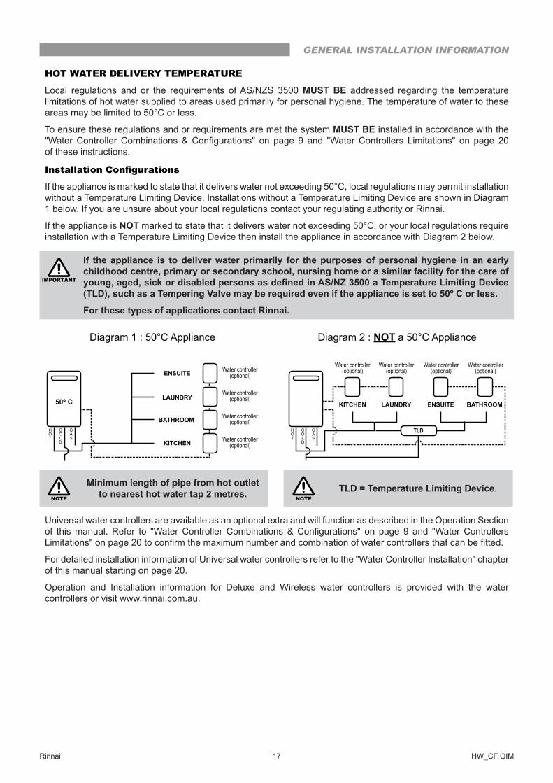
Installation Configurations
If the appliance is marked to state that it delivers water not exceeding 50°C, local regulations may permit installation without a Temperature Limiting Device� Installations without a Temperature Limiting Device are shown in Diagram 1 below� If you are unsure about your local regulations contact your regulating authority or Rinnai�
If the appliance is NOT marked to state that it delivers water not exceeding 50°C, or your local regulations require installation with a Temperature Limiting Device then install the appliance in accordance with Diagram 2 below�
IMPORTANT
If the appliance is to deliver water primarily for the purposes of personal hygiene in an early childhood centre, primary or secondary school, nursing home or a similar facility for the care of young, aged, sick or disabled persons as defined in AS/NZ 3500 a Temperature Limiting Device (TLD), such as a Tempering Valve may be required even if the appliance is set to 50º C or less�
For these types of applications contact Rinnai�
50º C
KITCHEN Water controller(optional)
Water controller(optional)
Water controller(optional)
Water controller(optional)
LAUNDRY
BATHROOM
ENSUITE
HOT
COLD
GAS
Diagram 1 : 50°C Appliance
KITCHEN
Water controller(optional)
Water controller(optional)
LAUNDRY BATHROOM
Water controller(optional)
Water controller(optional)
ENSUITE
TLDHOT
COLD
GAS
Diagram 2 : NOT a 50°C Appliance
NOTE
Minimum length of pipe from hot outlet to nearest hot water tap 2 metres� NOTE
TLD = Temperature Limiting Device�
Universal water controllers are available as an optional extra and will function as described in the Operation Section of this manual. Refer to "Water Controller Combinations & Configurations" on page 9 and "Water Controllers Limitations" on page 20 to confirm the maximum number and combination of water controllers that can be fitted.
For detailed installation information of Universal water controllers refer to the "Water Controller Installation" chapter of this manual starting on page 20�
Operation and Installation information for Deluxe and Wireless water controllers is provided with the water controllers or visit www�rinnai�com�au�
GENERAL INSTALLATION INFORMATION
Rinnai 18 HW_CF OIM
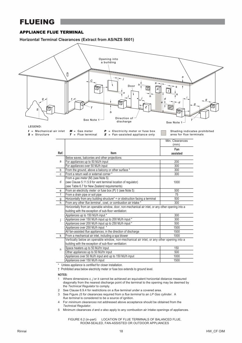
APPLIANCE FLUE TERMINAL
Horizontal Terminal Clearances (Extract from AS/NZS 5601)
Min� Clearances(mm)
For appliances up to 50 MJ/h input 200For appliances over 50 MJ/h input 300
300* ecafrus rehto ro ynoclab a evoba ,dnuorg eht morFb300* renroc lanretxe ro llaw nruter a tnorFc
dFrom a gas meter (M) (see Note 5)(see Clause 5.11.5.9 for vent terminal location of regulator)(see Table 6.7 for New Zealand requirements)
1000
e From an electricity meter or fuse box (P) † (see Note 5) 500epip lios ro epip niard a morFf
g Horizontally from any building structure* = or obstruction facing a terminal 500h From any other flue terminal , cowl, or combustion air intake * 300
Appliances up to 150 MJ/h input * 300Appliances over 150 MJ/h input up to 200 MJ/h input * 300Appliances over 200 MJ/h input up to 250 MJ/h input * 500Appliances over 250 MJ/h input * 1500All fan-assisted flue appliances, in the direction of discharge 1500
1000rewolb aps a gnidulcni ,telni ria lacinahcem a morFk
Space heaters up to 50 MJ/hr inputOther appliances up to 50 MJ/hr input 500Appliances over 50 MJ/h input and up to 150 MJ/h input 1000Appliances over 150 MJ/h input 1500
metI.feR
aBelow eaves, balconies and other projections:
FIGURE 6�2 (in-part) LOCATION OF FLUE TERMINALS OF BALANCED FLUE,ROOM-SEALED, FAN-ASSISTED OR OUTDOOR APPLIANCES
n
j
Horizontally from an openable window, door, non-mechanical air inlet, or any other opening into abuilding with the exception of sub-floor ventilation:
Vertically below an openable window, non-mechanical air inlet, or any other opening into abuilding with the exception of sub-floor ventilation:
Where dimensions c, j or k cannot be achieved an equivalent horizontal distance measureddiagonally from the nearest discharge point of the terminal to the opening may be deemed bythe Technical Regulator to comply� See Clause 6�9�4 for restrictions on a flue terminal under a covered area�See Figure J3 for clearances required from a flue terminal to an LP Gas cylinder� Aflue terminal is considered to be a source of ignition�For minimum clearances not addressed above acceptance should be obtained from the Technical Regulator�Minimum clearances d and e also apply to any combustion air intake openings of appliances�
1
23
4
5
* Unless appliance is certified for closer installation.† Prohibited area below electricity meter or fuse box extends to ground level. NOTES:
75
Shading indicates prohibitedarea for f lue terminals
LEGEND:
I = Mechanical air inletS = Structure
M = Gas meterT = Flue terminal
P = Electr ic ity meter or fuse boxZ = Fan-assisted appliance only
Direct ion ofdischarge
See Note 1See Note 1
Opening intoa bui lding
T
TT
T
T
T
T
C
M
dde
e
hj
j
j
n
b
f
a
h
P
ZS
k
k
g
gg
I
T
Door
Fanassisted
150
FLUEING
Rinnai 19 HW_CF OIM
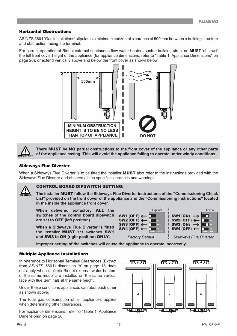
Horizontal Obstructions
AS/NZS 5601 ‘Gas Installations’ stipulates a minimum horizontal clearance of 500 mm between a building structure and obstruction facing the terminal�
For correct operation of Rinnai external continuous flow water heaters such a building structure MUST ‘obstruct’ the full front cover height of the appliance (for appliance dimensions, refer to "Table 1� Appliance Dimensions" on page 26), or extend vertically above and below the front cover as shown below.
IMPORTANT
There MUST be NO partial obstructions to the front cover of the appliance or any other parts of the appliance casing� This will avoid the appliance failing to operate under windy conditions�
Sideways Flue Diverter
When a Sideways Flue Diverter is to be fitted the installer MUST also refer to the instructions provided with the Sideways Flue Diverter and observe all the specific clearances and warnings.
WARNING
CONTROL BOARD DIPSWITCH SETTING:
The installer MUST follow the Sideways Flue Diverter instructions of the "Commissioning Check List" provided on the front cover of the appliance and the "Commissioning Instructions" located in the inside the appliance front cover�
When delivered ex-factory ALL the switches of the control board dipswitch are set to OFF (left position)�
When a Sideways Flue Diverter is fitted the installer MUST set switches SW1 and SW3 to ON (right position) ONLY�
Improper setting of the switches will cause the appliance to operate incorrectly�
Multiple Appliance Installations
In reference to Horizontal Terminal Clearances (Extract from AS/NZS 5601) dimension ‘h’ on page 18 does not apply when multiple Rinnai external water heaters of the same model are installed on the same vertical face with flue terminals at the same height.
Under these conditions appliances can abut each other as shown above�
The total gas consumption of all appliances applies when determining other clearances�
For appliance dimensions, refer to "Table 1� Appliance Dimensions" on page 26�
500mm
MINIMUM OBSTRUCTIONHEIGHT IS TO BE NO LESSTHAN TOP OF APPLIANCE
SW1 (OFF)SW2 (OFF)SW3 (OFF)SW4 (OFF) ON
12
34
DipSW
SW1 (ON)SW2 (OFF)SW3 (ON)SW4 (OFF) ON
12
34
DipSW
Factory Default Sideways Flue Diverter
FLUEING
Rinnai 20 HW_CF OIM
GENERAL INFORMATION
IMPORTANT
Other manufacturers water controllers are NOT compatible with Rinnai water heaters� Water controllers MUST NOT be used with any Solar Boost water heater� Rinnai water controllers brought in from other countries are not compatible with Rinnai appliances sold in Australia�
Regardless of water controller installation, all Rinnai water heaters must only be installed by an Authorised person�
Water controllers, transceivers and water heaters DO NOT contain user serviceable parts and must ONLY be serviced and repaired by an authorised person�
Master / Sub Water Controllers & Associated Temperatures
Only one MC model water controller can be designated as the 'Master' water controller� This water controller is normally used in the kitchen and usually has a maximum temperature of 55°C, which is sufficient for almost all kitchen applications� Temperatures higher than 55°C are possible but usually unnecessary and will result in higher gas use and increase the risk of burns�
Some additional conditions regarding Master Controller maximum temperatures apply when a wireless water controller is used as the 'Master' water controller�
(i) Temperatures of 55°C or higher can only be selected on the controller designated as the 'Master' water controller if the transceiver 'Max Temp' is also programmed to 55°C or higher�
(ii) The temperature of hot water delivered is always limited to the maximum temperature programmed into the water heater itself� For example, if the transceiver maximum temperature is programmed to 55°C and the water heater is limited to 50°C, the maximum temperature that the water heater will deliver is 50°C� In this case 55°C will be displayed on the wireless Master Controller until a tap is opened after which the display will revert to 50°C�
IMPORTANT
The water heater maximum temperature cannot be adjusted by the user� These adjustments can ONLY be carried out by a qualified and licensed trades person.
The remaining water controllers are designated 'sub' controllers and are for use in bathrooms, toilets and laundries� The temperature limit for all 'Sub' controllers is always 50°C to minimise the risk of burns in these areas�
Adhesive labels are included for individual identification of wireless water controllers as master (Kitchen) or sub (Bathroom) water controllers. These labels are usually placed on the top back of the wireless water controller body.
Water Controllers Limitations
An installation can have up to 4 universal MC-601Q water controllers�
Deluxe kitchen, bathroom and wireless water controllers are also available and various combinations of universal and the deluxe and wireless water controllers can be used with the following limitations:
• A maximum of 4 water controllers can be fitted.
• Only ONE master controller can be installed� This can be a deluxe kitchen, wireless or a universal (when programmed as a master controller) water controller.
IMPORTANT
When a deluxe kitchen is fitted it will always function as a master controller, this is the default setting and can not be changed�
• Up to TWO deluxe bathroom water controllers can be installed�
• The FOURTH water controller in any installation MUST BE a wireless or a universal water controller�
For more information regarding deluxe kitchen, bathroom and wireless water controllers, contact Rinnai or visit: www�rinnai�com�au�
WATER CONTROLLER INSTALLATION
Rinnai 21 HW_CF OIM
Location
NOTE
• DO NOT install water controllers near a heat source, such as a cook top, stove or oven� Heat, steam, smoke and hot oil may cause damage�
• DO NOT install water controllers outdoors unless protection from water / dust ingress and sunlight are provided�
• The water controller set as the MASTER water controller MUST NOT be installed in a bathroom�
• DO NOT install water controllers in direct sunlight�
• DO NOT install water controllers against a metal wall unless the wall is earthed in accordance with AN/NZS 3000�
• Water controllers MUST NOT be installed where chemicals such as benzene, alcohol, turpentine, hydrogen sulphide, ammonia, chlorine or other similar chemicals are in use�
The Water controller is a water resistant device, however excessive exposure to water may result in damage to the water controller� Durability is improved when positioned outside the shower recess�
• AVOID direct exposure to water or steam as these conditions may cause a malfunction�
• Water controllers must be installed in shaded and clean locations. They should be fitted out of reach of children (suggested height from floor to be at least 1500 mm). Water controllers MUST BE installed at least 400 mm above the highest part of a sink, basin or bath�
• When cleaning your water controller use ONLY a damp cloth and a mild detergent�
For water controller dimensions refer to "Table 1� Appliance Dimensions" and "Diagram 1� Dimensions" on page 26�
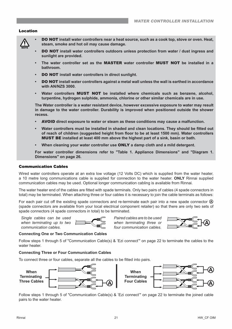
Communication Cables
Wired water controllers operate at an extra low voltage (12 Volts DC) which is supplied from the water heater, a 10 metre long communications cable is supplied for connection to the water heater� ONLY Rinnai supplied communication cables may be used� Optional longer communication cabling is available from Rinnai�
The water heater end of the cables are fitted with spade terminals. Only two pairs of cables (4 spade connectors in total) may be terminated. When attaching three or four cables it is necessary to join the cable terminals as follows:
For each pair cut off the existing spade connectors and re-terminate each pair into a new spade connector A (spade connectors are available from your local electrical component retailer) so that there are only two sets of spade connectors (4 spade connectors in total) to be terminated.
Single cables can be used when terminating up to two communication cables.
Paired cables are to be used when terminating three or four communication cables.
A
Connecting One or Two Communication Cables
Follow steps 1 through 5 of "Communication Cable(s) & ’Ezi connect’" on page 22 to terminate the cables to the water heater�
Connecting Three or Four Communication Cables
To connect three or four cables, separate all the cables to be fitted into pairs.
Follow steps 1 through 5 of "Communication Cable(s) & ’Ezi connect’" on page 22 to terminate the joined cable pairs to the water heater�
WhenTerminating Three Cables
WhenTerminatingFour CablesA
A
A
WATER CONTROLLER INSTALLATION
Rinnai 22 HW_CF OIM
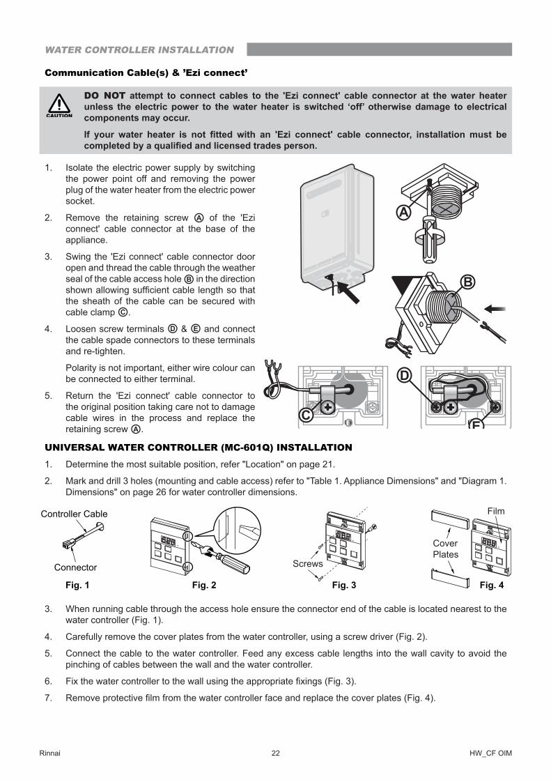
Communication Cable(s) & ’Ezi connect’
CAUTION
DO NOT attempt to connect cables to the 'Ezi connect' cable connector at the water heater unless the electric power to the water heater is switched ‘off’ otherwise damage to electrical components may occur�
If your water heater is not fitted with an 'Ezi connect' cable connector, installation must be completed by a qualified and licensed trades person.
1� Isolate the electric power supply by switching the power point off and removing the power plug of the water heater from the electric power socket�
2� Remove the retaining screw A of the 'Ezi connect' cable connector at the base of the appliance�
3� Swing the 'Ezi connect' cable connector door open and thread the cable through the weather seal of the cable access hole B in the direction shown allowing sufficient cable length so that the sheath of the cable can be secured with cable clamp C �
4� Loosen screw terminals D & E and connect the cable spade connectors to these terminals and re-tighten�
Polarity is not important, either wire colour can be connected to either terminal�
5� Return the 'Ezi connect' cable connector to the original position taking care not to damage cable wires in the process and replace the retaining screw A �
UNIVERSAL WATER CONTROLLER (MC-601Q) INSTALLATION
1� Determine the most suitable position, refer "Location" on page 21�
2� Mark and drill 3 holes (mounting and cable access) refer to "Table 1. Appliance Dimensions" and "Diagram 1. Dimensions" on page 26 for water controller dimensions�
3� When running cable through the access hole ensure the connector end of the cable is located nearest to the water controller (Fig. 1).
4� Carefully remove the cover plates from the water controller, using a screw driver (Fig. 2).
5� Connect the cable to the water controller� Feed any excess cable lengths into the wall cavity to avoid the pinching of cables between the wall and the water controller�
6� Fix the water controller to the wall using the appropriate fixings (Fig. 3).
7� Remove protective film from the water controller face and replace the cover plates (Fig. 4).
A
CE
D
B
Connector
Controller Cable
Screws
Film
Fig� 1 Fig� 2 Fig� 3 Fig� 4
CoverPlates
WATER CONTROLLER INSTALLATION
Rinnai 23 HW_CF OIM
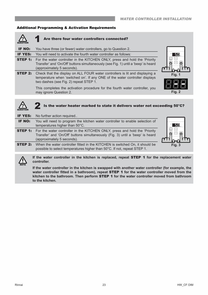
Additional Programming & Activation Requirements
QUESTION? 1 Are there four water controllers connected?
IF NO: You have three (or fewer) water controllers, go to Question 2.IF YES: You will need to activate the fourth water controller as follows:STEP 1: For the water controller in the KITCHEN ONLY, press and hold the ‘Priority
Transfer’ and ‘On/Off’ buttons simultaneously (see Fig. 1) until a ‘beep’ is heard (approximately 5 seconds).
STEP 2: Check that the display on ALL FOUR water controllers is lit and displaying a temperature when ‘switched on’� If any ONE of the water controller displays two dashes (see Fig. 2) repeat STEP 1.
This completes the activation procedure for the fourth water controller, you may ignore Question 2�
QUESTION? 2 Is the water heater marked to state it delivers water not exceeding 50°C?
IF YES: No further action required..IF NO: You will need to program the kitchen water controller to enable selection of
temperatures higher than 50°C�STEP 1: For the water controller in the KITCHEN ONLY, press and hold the ‘Priority
Transfer’ and ‘On/Off’ buttons simultaneously (Fig. 3) until a ‘beep’ is heard (approximately 5 seconds).
STEP 2: When the water controller fitted in the KITCHEN is switched On, it should be possible to select temperatures higher than 50°C� If not, repeat STEP 1�
NOTE
If the water controller in the kitchen is replaced, repeat STEP 1 for the replacement water controller�
If the water controller in the kitchen is swapped with another water controller (for example, the water controller fitted in a bathroom), repeat STEP 1 for the water controller moved from the kitchen to the bathroom� Then perform STEP 1 for the water controller moved from bathroom to the kitchen�
Fig� 1
Fig� 2
Fig� 3
WATER CONTROLLER INSTALLATION
Rinnai 24 HW_CF OIM
TESTING
1� Before final connection of the water heater purge gas, hot water and cold water supply lines. Debris or swarf in either the gas or water supplies may cause damage�
2� Turn on gas and cold water supplies�
3� Test for water leaks and gas escapes near the unit�
4� Isolate gas supply� Remove test point screw located on the gas inlet connection and attach pressure gauge�
IMPORTANT
Confirm the control board dipswitch settings are set to the correct positions as required , i.e. factory default or with a Sideways Flue Diverter fitted, see "Sideways Flue Diverter" on page 19 for details�
5� Turn the power 'on' at the power point socket and turn on gas�
6� If water controllers are fitted, ensure they are 'ON', with the maximum delivery temperature selected and open ALL available hot water outlets�
If water controllers are not fitted, simply open ALL available hot water outlets�
CAUTION
Ensure building occupants DO NOT have access to hot water outlets during this procedure�
7� Operate ALL other gas appliances at their maximum gas rate, in accordance with manufacturers instructions�
8� With all gas appliances in operation at maximum gas rate, the pressure should read between 1�13 - 3�0 kPa on Natural Gas. On LPG the pressure should be 2.75 - 3.0 kPa. If the pressure is lower, the gas supply is inadequate and the appliance will not operate to specification. It is the Installers responsibility to check the gas meter, service regulator and pipe work for correct operation/sizing and rectify as required.
NOTE
The gas regulator on the appliance is electronically controlled and factory pre-set� Under normal circumstances it DOES NOT need adjustment during installation�
9� Close hot water taps including the shower�
10� Inspect and clean the strainer located on the cold water inlet connection� This procedure may need to be repeated to ensure the strainer remains clear, especially on new installations�
11� If water controllers are fitted, it is necessary to test their operation through the complete range of functions (refer to the Operation sections of this manual).
12� Confirm the hot water delivery temperature(s) using a thermometer. If controllers are fitted, ensure temperatures exceeding 50°C cannot be selected on bathroom or ensuite controllers� Refer to the section ‘Delivery Temperature’ below for more details�
13� After testing is completed, explain to the householder the functions and operation of the water heater and water controllers (if fitted). Ensure the "Installation Record" on page 25 is filled in and that this booklet is handed to the customer� Reminding the customer to complete the Warranty Card and forward to Rinnai�
DELIVERY TEMPERATURE
50°C Compliant Models
"50°C Compliant" appliances are factory set to deliver a maximum temperature not exceeding 50°C. For fine tuning they have an incremental adjustment mechanism that allows the installer to increase the appliance delivery temperature incrementally from the 'Factory Set’ value to temperatures slightly exceeding 50°C� This is intended to enable compensation for temperature losses in the pipe-work between the water heater and any outlets and achieve the required temperature at the outlet. Instructions for incremental temperature adjustment are located in the instruction pocket inside the appliance front cover�
For All Other Models
Rinnai continuous flow water heaters are factory pre-set to various maximum delivery temperatures depending on model and their intended application� For the majority of applications, the factory pre-set temperature is appropriate� In the unlikely event it is not this setting can be increased or decreased by the installer� Instructions for changing the maximum delivery temperature are located in the instruction pocket inside the appliance front cover�
COMMISSIONING
Rinnai 25 HW_CF OIM
GAS PRESSURE SETTING
The regulator is electronically controlled and factory pre-set� Under normal circumstances it DOES NOT require adjustment during installation� Make adjustments ONLY if the unit is not operating correctly and all other possible causes for incorrect operation have been eliminated� Instructions for gas pressure setting are located in the instruction pocket inside the appliance front cover�
NOTE
For all injector size and gas pressure values refer to the appliance data plate, located on the left hand side of the water heater�
WIRING DIAGRAM
The wiring diagram is located in the instruction pocket inside the appliance front cover�
COMMISSIONING CHECK LIST
A commissioning check list is provided on the appliance front cover to enable the installer to step through the correct commissioning procedure when installing a Rinnai Continuous Flow water heater�
The check list can also assist the installer to identify potential installation errors that may prevent the appliance from operating correctly�
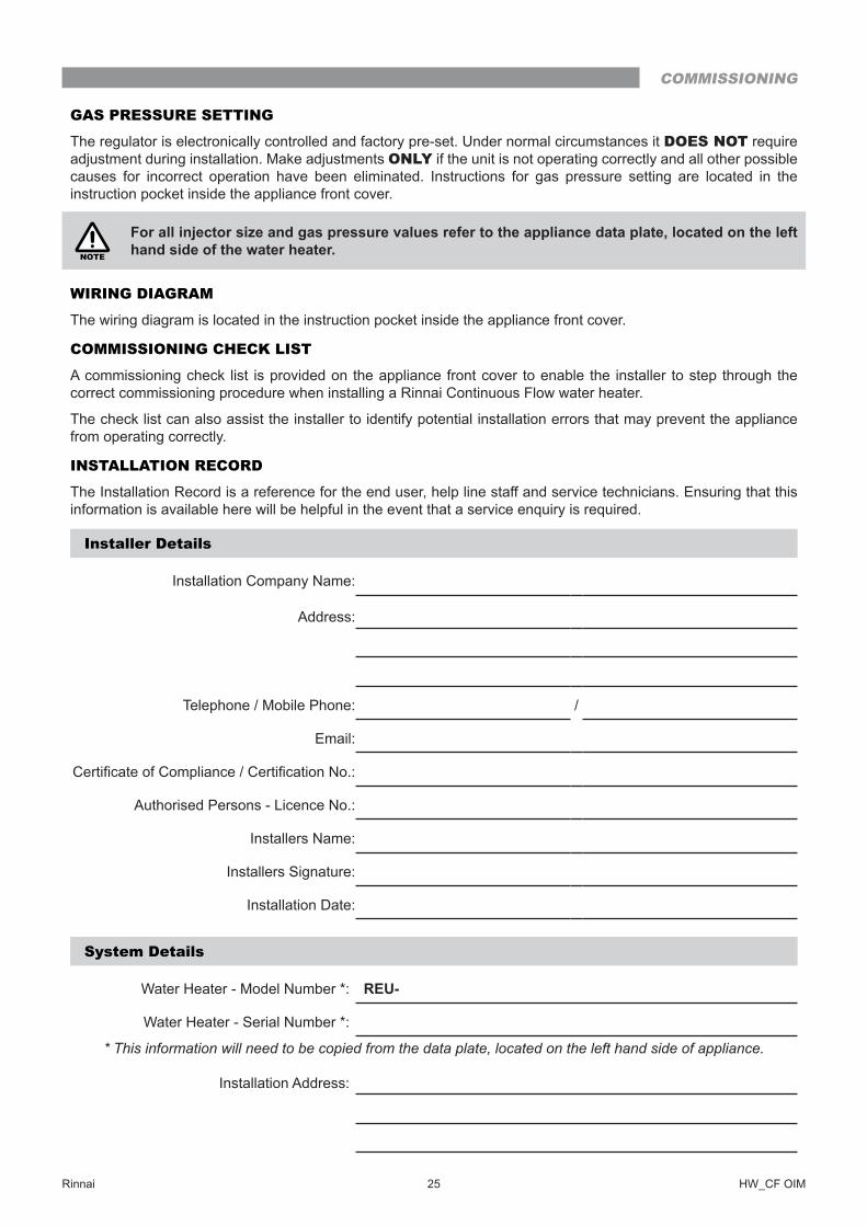
INSTALLATION RECORD
The Installation Record is a reference for the end user, help line staff and service technicians� Ensuring that this information is available here will be helpful in the event that a service enquiry is required.
Installer Details
Installation Company Name:
Address:
Telephone / Mobile Phone: /
Email:
Certificate of Compliance / Certification No.:
Authorised Persons - Licence No�:
Installers Name:
Installers Signature:
Installation Date:
System Details
Water Heater - Model Number *: REU-
Water Heater - Serial Number *:
* This information will need to be copied from the data plate, located on the left hand side of appliance.
Installation Address:
COMMISSIONING
Rinnai 26 HW_CF OIM
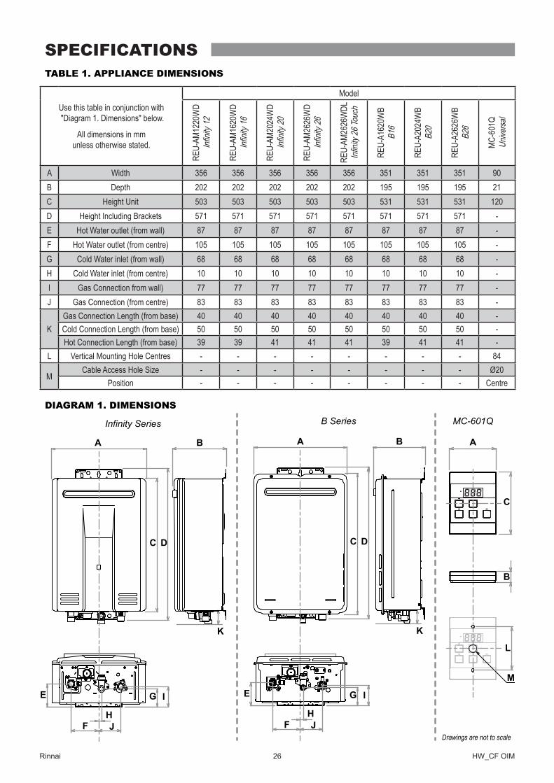
TABLE 1. APPLIANCE DIMENSIONS
Use this table in conjunction with "Diagram 1. Dimensions" below.
All dimensions in mm unless otherwise stated.
Model
REU-
AM12
20W
D Infi
nity 1
2
REU-
AM16
20W
D Infi
nity 1
6
REU-
AM20
24W
D Infi
nity 2
0
REU-
AM26
26W
D Infi
nity 2
6
REU-
AM26
26W
DL
Infinit
y 26 T
ouch
REU-
A162
0WB
B16
REU-
A202
4WB
B20
REU-
A262
6WB
B26
MC-6
01Q
Unive
rsal
A Width 356 356 356 356 356 351 351 351 90B Depth 202 202 202 202 202 195 195 195 21C Height Unit 503 503 503 503 503 531 531 531 120D Height Including Brackets 571 571 571 571 571 571 571 571 -E Hot Water outlet (from wall) 87 87 87 87 87 87 87 87 -F Hot Water outlet (from centre) 105 105 105 105 105 105 105 105 -G Cold Water inlet (from wall) 68 68 68 68 68 68 68 68 -H Cold Water inlet (from centre) 10 10 10 10 10 10 10 10 -I Gas Connection from wall) 77 77 77 77 77 77 77 77 -J Gas Connection (from centre) 83 83 83 83 83 83 83 83 -
KGas Connection Length (from base) 40 40 40 40 40 40 40 40 -Cold Connection Length (from base) 50 50 50 50 50 50 50 50 -Hot Connection Length (from base) 39 39 41 41 41 39 41 41 -
L Vertical Mounting Hole Centres - - - - - - - - 84
MCable Access Hole Size - - - - - - - - Ø20
Position - - - - - - - - Centre
DIAGRAM 1. DIMENSIONS
KK
A
B
C
MC-601Q
B B
Drawings are not to scale
DC
A
E
F JH
IG
Infinity Series
DC
A
E
F JH
IG
B Series
M
L
SPECIFICATIONS
Rinnai 27 HW_CF OIM
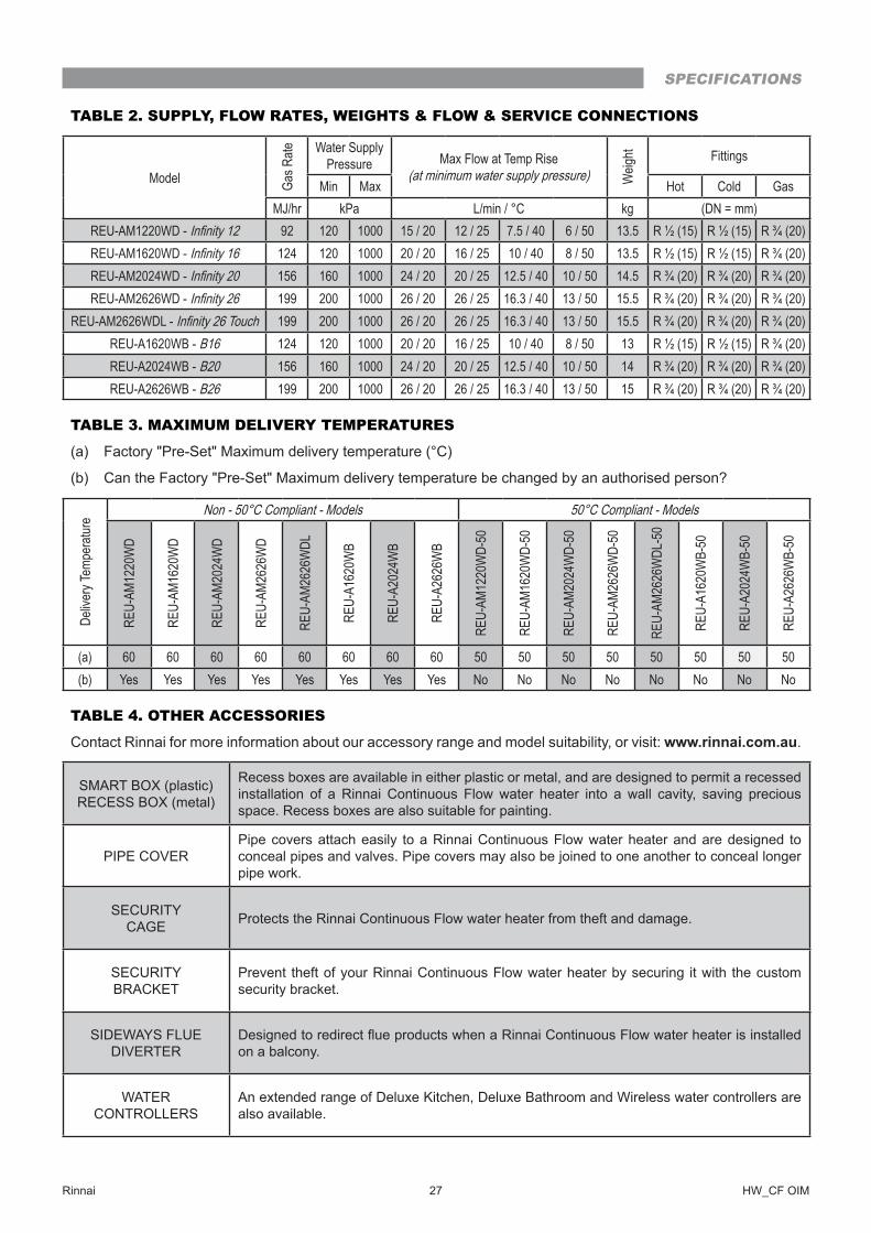
TABLE 2. SUPPLY, FLOW RATES, WEIGHTS & FLOW & SERVICE CONNECTIONS
Model Gas R
ate Water Supply Pressure Max Flow at Temp Rise
(at minimum water supply pressure) Weig
ht Fittings
Min Max Hot Cold GasMJ/hr kPa L/min / °C kg (DN = mm)
REU-AM1220WD - Infinity 12 92 120 1000 15 / 20 12 / 25 7.5 / 40 6 / 50 13.5 R ½ (15) R ½ (15) R ¾ (20)REU-AM1620WD - Infinity 16 124 120 1000 20 / 20 16 / 25 10 / 40 8 / 50 13.5 R ½ (15) R ½ (15) R ¾ (20)REU-AM2024WD - Infinity 20 156 160 1000 24 / 20 20 / 25 12.5 / 40 10 / 50 14.5 R ¾ (20) R ¾ (20) R ¾ (20)REU-AM2626WD - Infinity 26 199 200 1000 26 / 20 26 / 25 16.3 / 40 13 / 50 15.5 R ¾ (20) R ¾ (20) R ¾ (20)
REU-AM2626WDL - Infinity 26 Touch 199 200 1000 26 / 20 26 / 25 16.3 / 40 13 / 50 15.5 R ¾ (20) R ¾ (20) R ¾ (20)REU-A1620WB - B16 124 120 1000 20 / 20 16 / 25 10 / 40 8 / 50 13 R ½ (15) R ½ (15) R ¾ (20)REU-A2024WB - B20 156 160 1000 24 / 20 20 / 25 12.5 / 40 10 / 50 14 R ¾ (20) R ¾ (20) R ¾ (20)REU-A2626WB - B26 199 200 1000 26 / 20 26 / 25 16.3 / 40 13 / 50 15 R ¾ (20) R ¾ (20) R ¾ (20)
TABLE 3. MAXIMUM DELIVERY TEMPERATURES
(a) Factory "Pre-Set" Maximum delivery temperature (°C)
(b) Can the Factory "Pre-Set" Maximum delivery temperature be changed by an authorised person?
Deliv
ery T
empe
ratur
e Non - 50°C Compliant - Models 50°C Compliant - Models
REU-
AM12
20W
D
REU-
AM16
20W
D
REU-
AM20
24W
D
REU-
AM26
26W
D
REU-
AM26
26W
DL
REU-
A162
0WB
REU-
A202
4WB
REU-
A262
6WB
REU-
AM12
20W
D-50
REU-
AM16
20W
D-50
REU-
AM20
24W
D-50
REU-
AM26
26W
D-50
REU-
AM26
26W
DL-5
0
REU-
A162
0WB-
50
REU-
A202
4WB-
50
REU-
A262
6WB-
50
(a) 60 60 60 60 60 60 60 60 50 50 50 50 50 50 50 50(b) Yes Yes Yes Yes Yes Yes Yes Yes No No No No No No No No
TABLE 4. OTHER ACCESSORIES
Contact Rinnai for more information about our accessory range and model suitability, or visit: www�rinnai�com�au�
SMART BOX (plastic)RECESS BOX (metal)
Recess boxes are available in either plastic or metal, and are designed to permit a recessed installation of a Rinnai Continuous Flow water heater into a wall cavity, saving precious space� Recess boxes are also suitable for painting�
PIPE COVERPipe covers attach easily to a Rinnai Continuous Flow water heater and are designed to conceal pipes and valves� Pipe covers may also be joined to one another to conceal longer pipe work�
SECURITY CAGE Protects the Rinnai Continuous Flow water heater from theft and damage�
SECURITY BRACKET
Prevent theft of your Rinnai Continuous Flow water heater by securing it with the custom security bracket�
SIDEWAYS FLUE DIVERTER
Designed to redirect flue products when a Rinnai Continuous Flow water heater is installed on a balcony�
WATER CONTROLLERS
An extended range of Deluxe Kitchen, Deluxe Bathroom and Wireless water controllers are also available�
SPECIFICATIONS
Rinnai Australia Pty Ltd ABN 74 005 138 769
100 Atlantic Drive, Keysborough,Victoria 3173
P.O. Box 460, Braeside, Victoria 3195
Tel: (03) 9271 6625 Fax: (03) 9271 6622
U340-1330(01)
28 HW_CF OIM Issue 1 - Oct 2017