Embed Size (px)
Citation preview
2www.dryvit.com • 800-556-7752
Continuous Insulationand
Air Barriersfor
High Performance Walls
3
Dryvit Systems, Inc. is a Registered Provider with The American Institute of Architects Continuing Education Systems. Credit earned on completion of this program will be reported to CES Records for AIA members. Certificates of Completion for non-AIA members available on request.
This program is registered with the AIA/CES for continuing professional education. As such, it does not include content that may be deemed or construed to be an approval or endorsement by the AIA of any material of construction or any method or manner of handling, using, distributing, or dealing in any material or product. Questions related to specific materials, methods, and services will be addressed at the conclusion of this presentation.
Thank you!
AIA / CESAIA / CES
www.dryvit.com • 800-556-7752
4
USGBC Education ProviderUSGBC Education Provider
LEED Continuing Education Credits
1.0 GBCI CE Hours
(Green Building Certification Institute)
5
This presentation is protected by US and international copyright laws. Reproduction, distribution, display and use of the
presentation without written permission of Dryvit Systems, Inc. is prohibited.
© Dryvit Systems, Inc. 2013
Copyrighted MaterialCopyrighted Material
www.dryvit.com • 800-556-7752
6
Learning ObjectivesLearning Objectives
1. Introduce New Energy Code and Design Standards for continuous insulation (ci) and air barriers requirements for exterior framed wall assemblies.
2. Deconstruct “perceived” value of traditional cavity insulation methods and Reconstruct new strategies for higher “effective” value of exterior continuous insulation opportunities.
3. Outline the challenges in framed wall design and detailing associated with the integration of continuous insulation (ci) behind traditional veneer cladding.
4. Understand the interrelationship between continuous insulation (ci) and improved energy efficiency, reduced energy consumption and overall improved building envelope performance.
www.dryvit.com • 800-556-7752
7
Goals and ObjectivesGoals and Objectives
• New Building Code Requirements– IBC, IECC / ASHRAE Standard 90.1
• Building Envelope Performance • Fire Testing• Energy Efficiency
• Framed Wall Performance– Cavity vs. Continuous Insulation (CI)
• Wall Insulation Requirements• Coordinating the addition of CI
– Integrating CI behind Traditional Claddings• Exterior Insulated Claddings as a CI Solution
– Metal Panel, Joint Venture Systems, EIFS– Diversity for architectural style and aesthetic appearance
• Construction Cost Savings

Wall ComponentsAir / water-resistive barrierExterior sheathing• Fire rated as necessaryStud framing• Metal or wood• Nominal - 4”, 6”, 8” depthsCavity insulation• Measured in R-valueVapor retarder - interior• Climate zones 5-8 & Marine 4Interior drywall • Fire rated as necessary
8
Typical Commercial Framed WallTypical Commercial Framed Wall
Building Code RequirementsBuilding Code Requirements
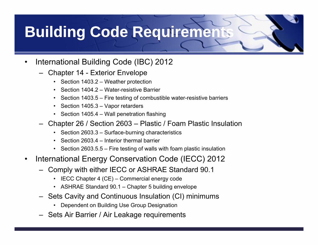
• International Building Code (IBC) 2012– Chapter 14 - Exterior Envelope
• Section 1403.2 – Weather protection• Section 1404.2 – Water-resistive Barrier• Section 1403.5 – Fire testing of combustible water-resistive barriers• Section 1405.3 – Vapor retarders• Section 1405.4 – Wall penetration flashing
– Chapter 26 / Section 2603 – Plastic / Foam Plastic Insulation• Section 2603.3 – Surface-burning characteristics• Section 2603.4 – Interior thermal barrier• Section 2603.5.5 – Fire testing of walls with foam plastic insulation
• International Energy Conservation Code (IECC) 2012– Comply with either IECC or ASHRAE Standard 90.1
• IECC Chapter 4 (CE) – Commercial energy code• ASHRAE Standard 90.1 – Chapter 5 building envelope
– Sets Cavity and Continuous Insulation (CI) minimums• Dependent on Building Use Group Designation
– Sets Air Barrier / Air Leakage requirements9
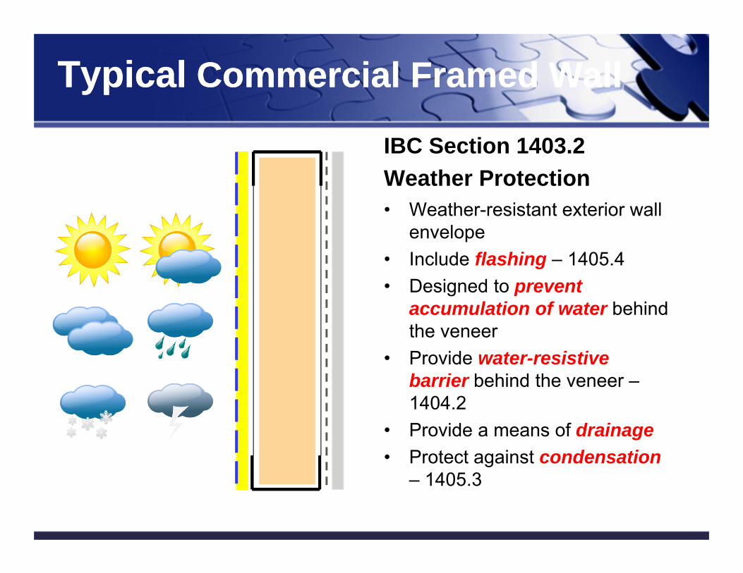
IBC Section 1403.2 Weather Protection• Weather-resistant exterior wall
envelope• Include flashing – 1405.4• Designed to prevent
accumulation of water behind the veneer
• Provide water-resistive barrier behind the veneer –1404.2
• Provide a means of drainage• Protect against condensation
– 1405.3
10
Typical Commercial Framed WallTypical Commercial Framed Wall
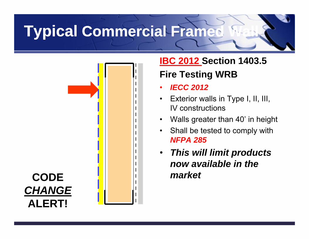
IBC 2012 Section 1403.5 Fire Testing WRB• IECC 2012• Exterior walls in Type I, II, III,
IV constructions• Walls greater than 40’ in height• Shall be tested to comply with
NFPA 285• This will limit products
now available in the market
11
Typical Commercial Framed WallTypical Commercial Framed Wall
CODECHANGEALERT!
Energy Code RequirementsEnergy Code Requirements
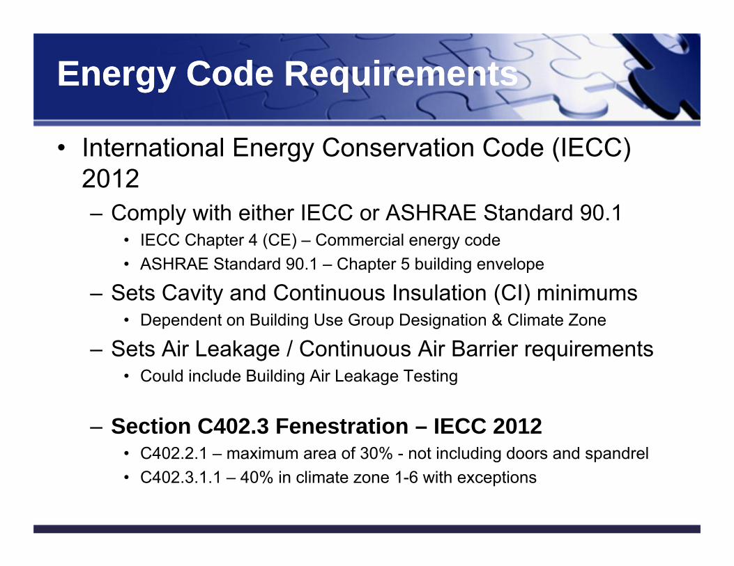
• International Energy Conservation Code (IECC) 2012– Comply with either IECC or ASHRAE Standard 90.1
• IECC Chapter 4 (CE) – Commercial energy code• ASHRAE Standard 90.1 – Chapter 5 building envelope
– Sets Cavity and Continuous Insulation (CI) minimums• Dependent on Building Use Group Designation & Climate Zone
– Sets Air Leakage / Continuous Air Barrier requirements• Could include Building Air Leakage Testing
– Section C402.3 Fenestration – IECC 2012• C402.2.1 – maximum area of 30% - not including doors and spandrel• C402.3.1.1 – 40% in climate zone 1-6 with exceptions
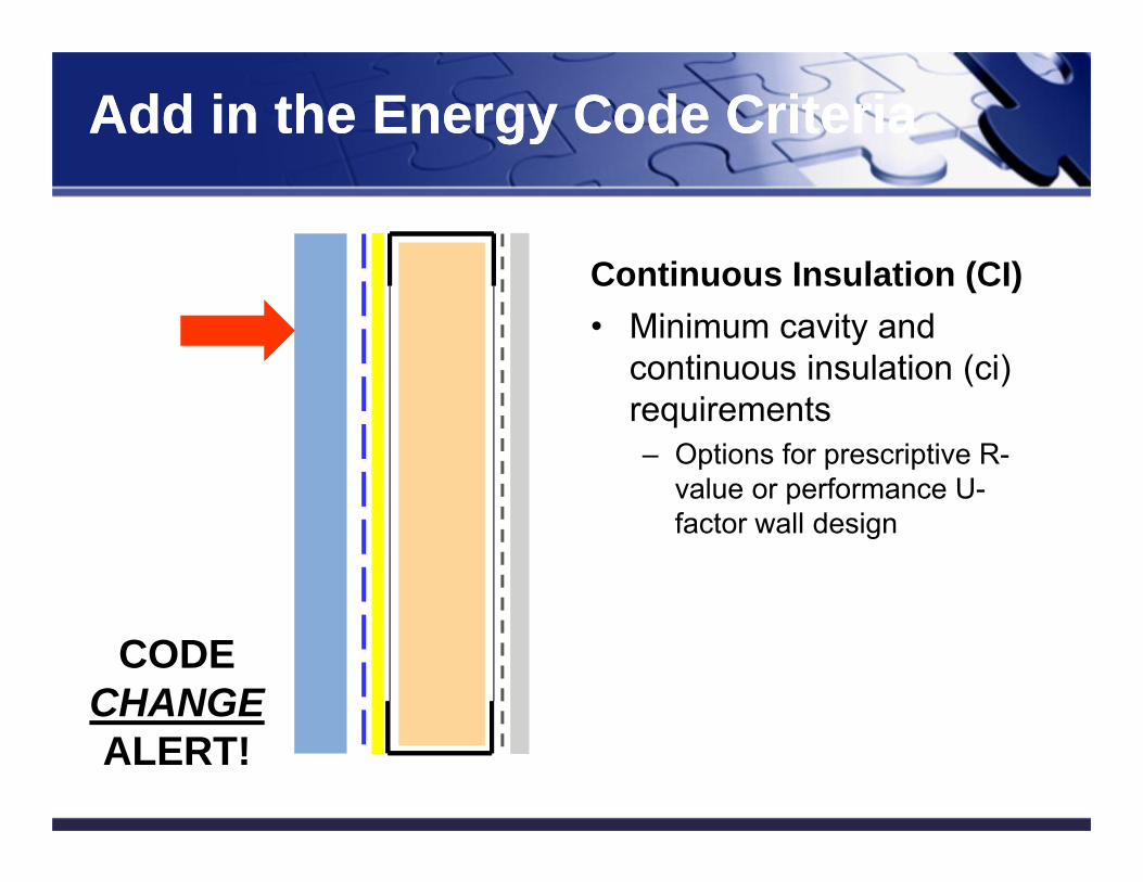
Continuous Insulation (CI)• Minimum cavity and
continuous insulation (ci) requirements– Options for prescriptive R-
value or performance U-factor wall design
13
Add in the Energy Code CriteriaAdd in the Energy Code Criteria
CODECHANGEALERT!
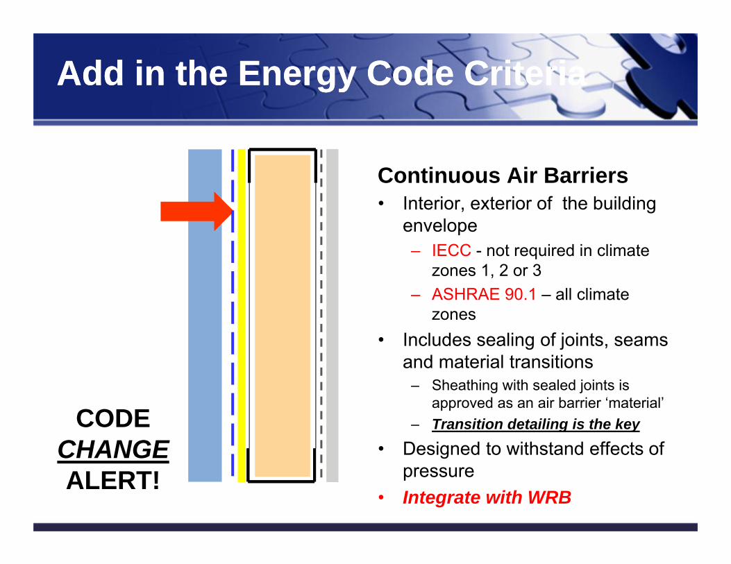
Continuous Air Barriers• Interior, exterior of the building
envelope– IECC - not required in climate
zones 1, 2 or 3– ASHRAE 90.1 – all climate
zones• Includes sealing of joints, seams
and material transitions– Sheathing with sealed joints is
approved as an air barrier ‘material’– Transition detailing is the key
• Designed to withstand effects of pressure
• Integrate with WRB14
Add in the Energy Code CriteriaAdd in the Energy Code Criteria
CODECHANGEALERT!
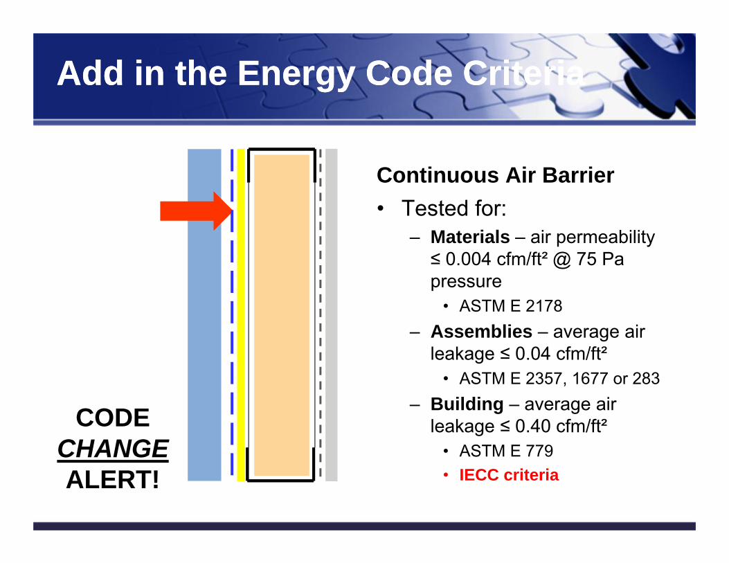
Continuous Air Barrier• Tested for:
– Materials – air permeability ≤ 0.004 cfm/ft² @ 75 Pa pressure
• ASTM E 2178– Assemblies – average air
leakage ≤ 0.04 cfm/ft²• ASTM E 2357, 1677 or 283
– Building – average air leakage ≤ 0.40 cfm/ft²
• ASTM E 779• IECC criteria
15
Add in the Energy Code CriteriaAdd in the Energy Code Criteria
CODECHANGEALERT!
16
Building Code RequirementsBuilding Code Requirements
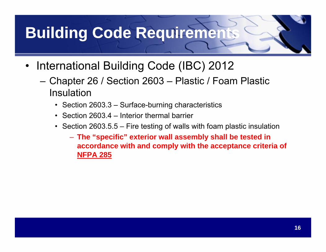
• International Building Code (IBC) 2012– Chapter 26 / Section 2603 – Plastic / Foam Plastic
Insulation• Section 2603.3 – Surface-burning characteristics• Section 2603.4 – Interior thermal barrier• Section 2603.5.5 – Fire testing of walls with foam plastic insulation
– The “specific” exterior wall assembly shall be tested in accordance with and comply with the acceptance criteria of NFPA 285
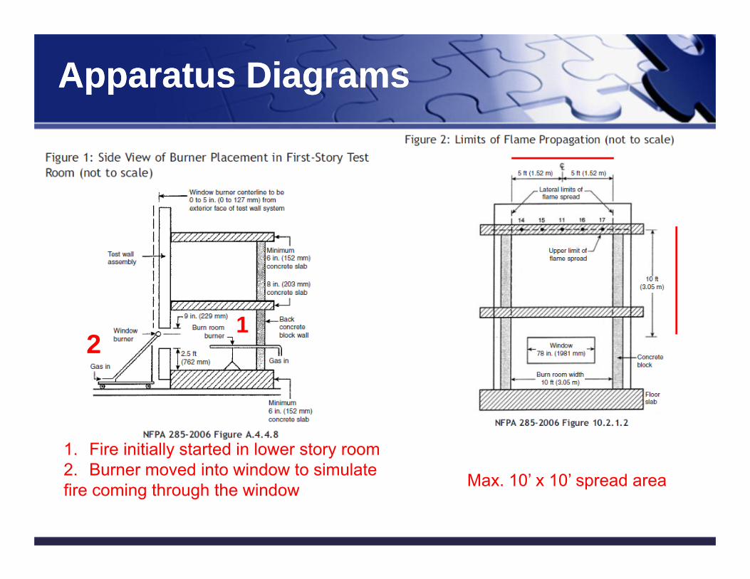
Apparatus DiagramsApparatus Diagrams
Max. 10’ x 10’ spread area
1. Fire initially started in lower story room2. Burner moved into window to simulate fire coming through the window
12
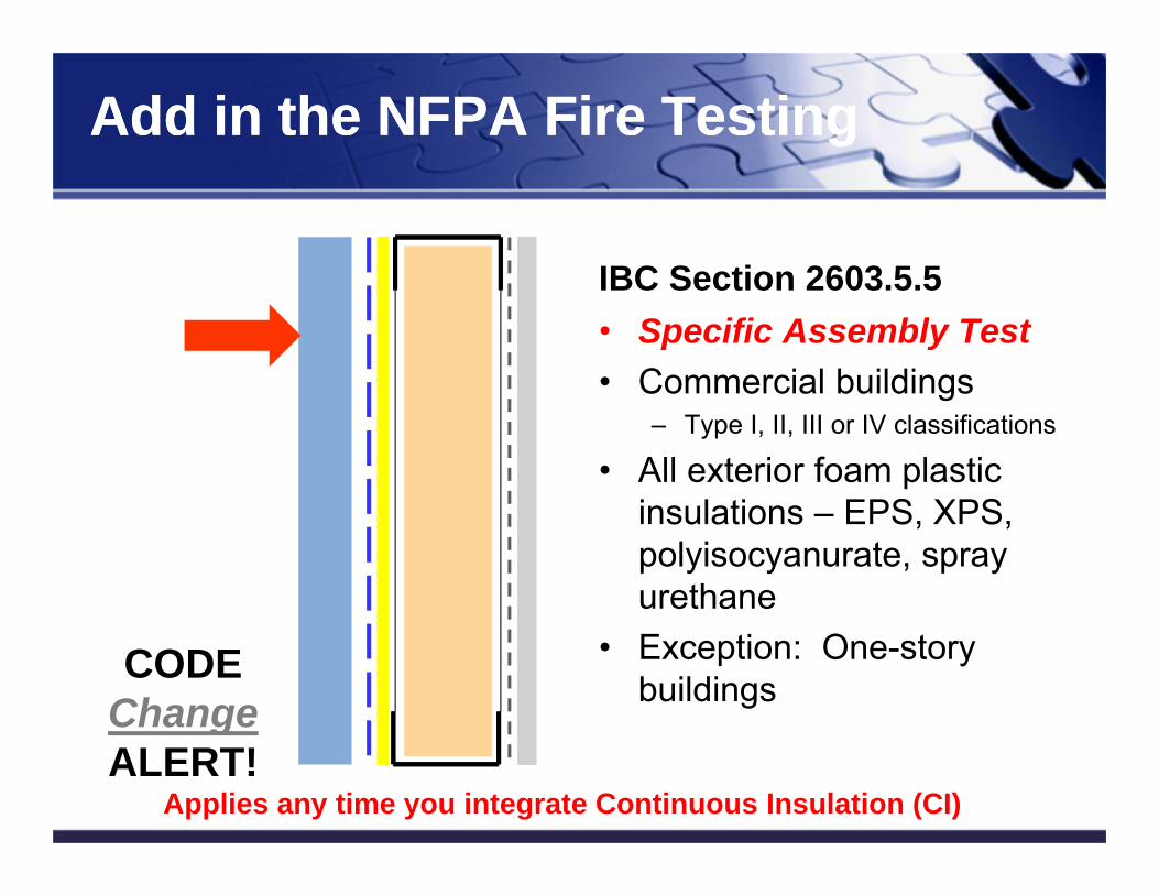
IBC Section 2603.5.5• Specific Assembly Test• Commercial buildings
– Type I, II, III or IV classifications
• All exterior foam plastic insulations – EPS, XPS, polyisocyanurate, spray urethane
• Exception: One-story buildings
18
Add in the NFPA Fire TestingAdd in the NFPA Fire Testing
Applies any time you integrate Continuous Insulation (CI)
CODEChangeALERT!
19
What’s next in Energy Codes?What’s next in Energy Codes?
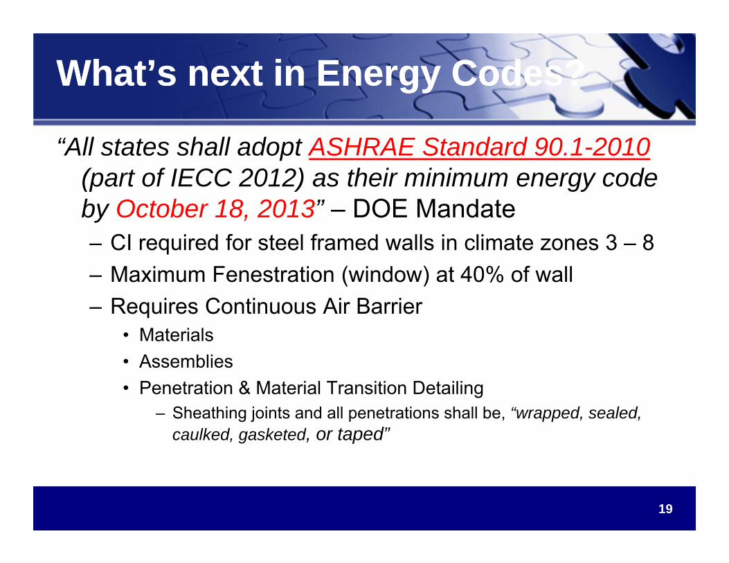
“All states shall adopt ASHRAE Standard 90.1-2010 (part of IECC 2012) as their minimum energy code by October 18, 2013” – DOE Mandate– CI required for steel framed walls in climate zones 3 – 8– Maximum Fenestration (window) at 40% of wall– Requires Continuous Air Barrier
• Materials• Assemblies• Penetration & Material Transition Detailing
– Sheathing joints and all penetrations shall be, “wrapped, sealed, caulked, gasketed, or taped”
20
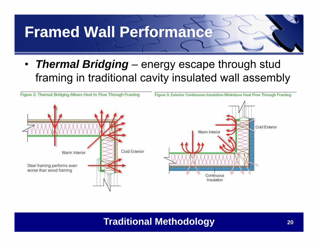
Framed Wall PerformanceFramed Wall Performance
• Thermal Bridging – energy escape through stud framing in traditional cavity insulated wall assembly
Traditional Methodology
21
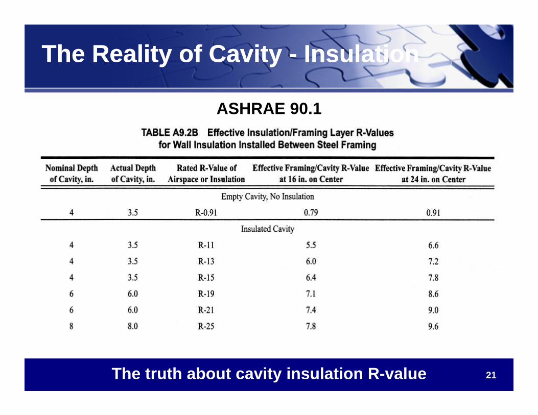
The Reality of Cavity - InsulationThe Reality of Cavity - Insulation
The truth about cavity insulation R-value
ASHRAE 90.1
22
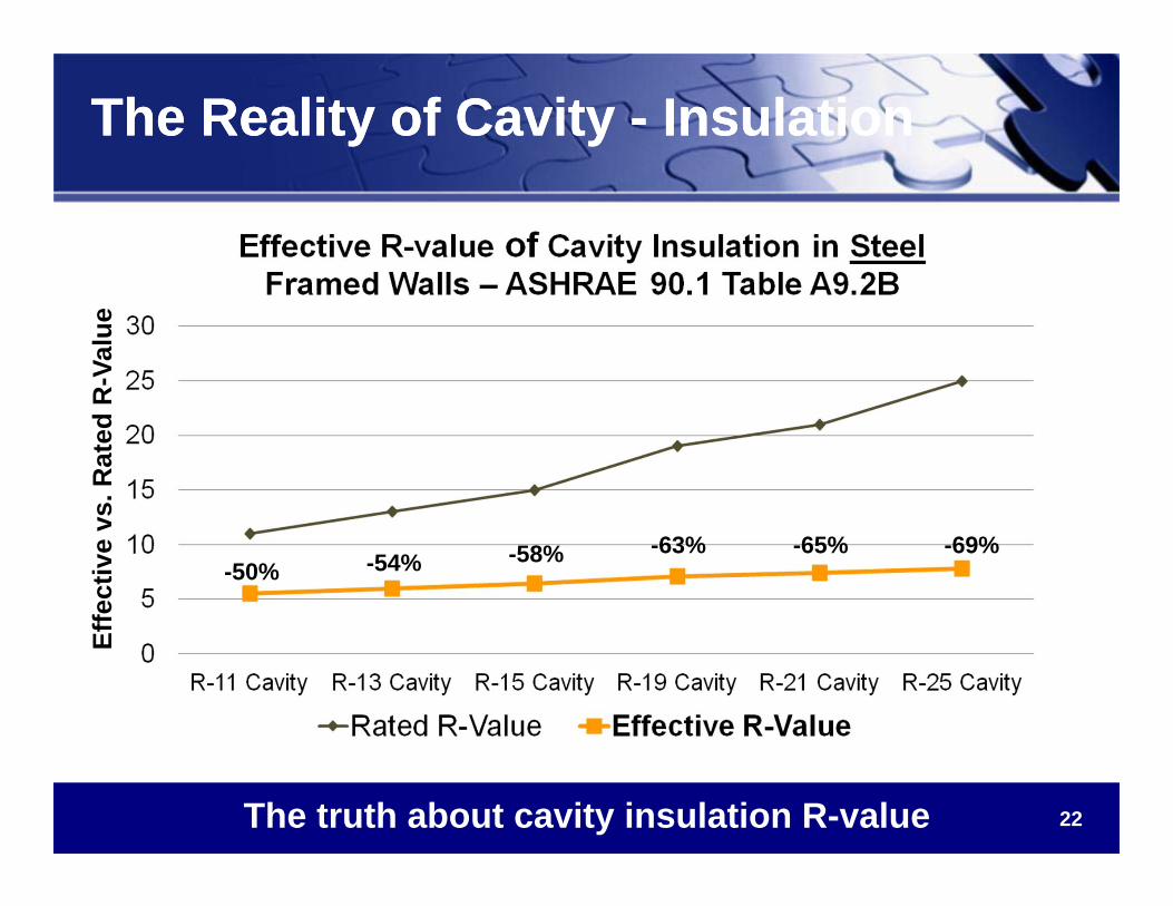
The Reality of Cavity - InsulationThe Reality of Cavity - Insulation
The truth about cavity insulation R-value
Effe
ctiv
e vs
. Rat
ed R
-Val
ue
-65% -69%-63%-58%-54%-50%
23
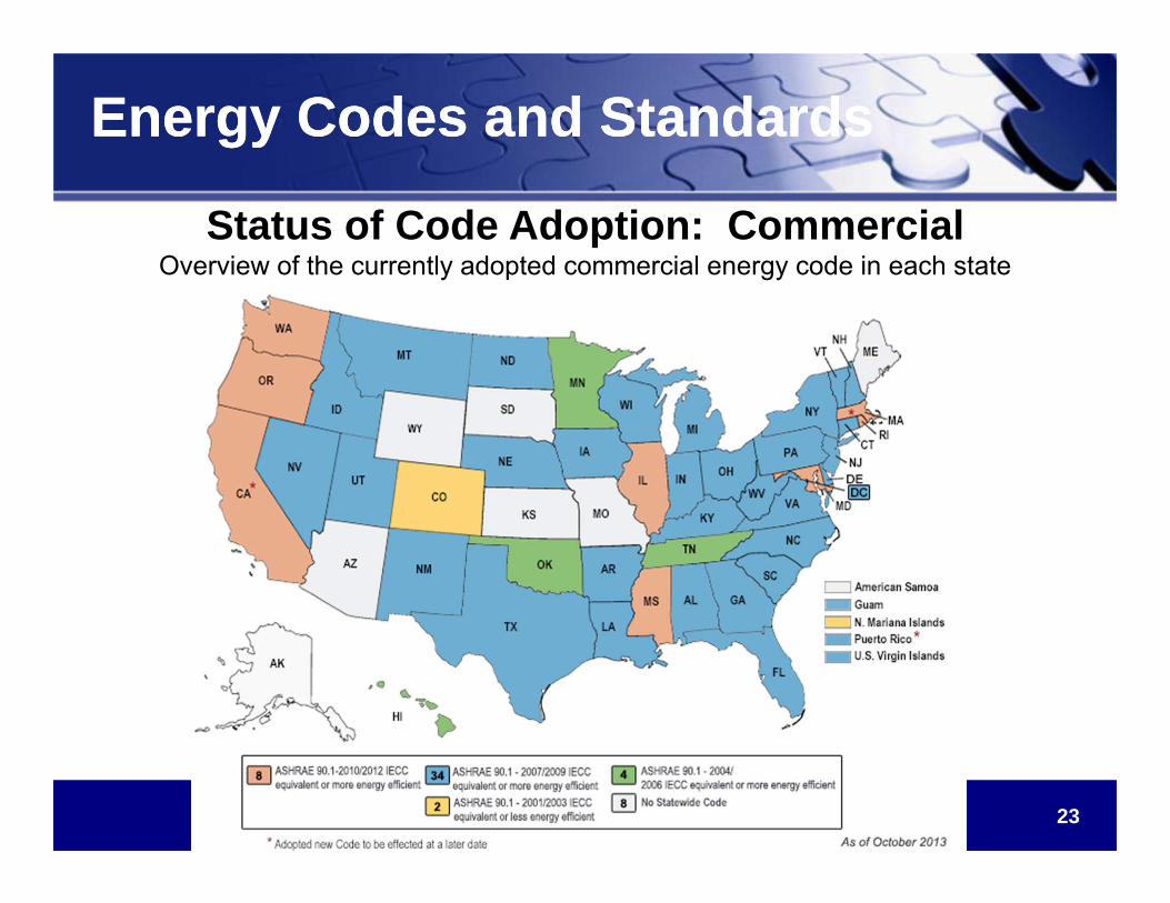
Energy Codes and StandardsEnergy Codes and Standards
Status of Code Adoption: CommercialOverview of the currently adopted commercial energy code in each state
as of October, 2012
24
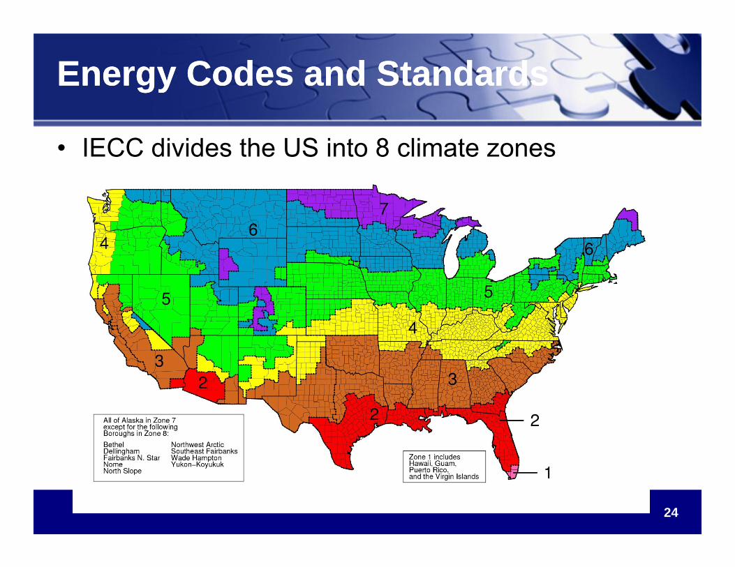
Energy Codes and StandardsEnergy Codes and Standards
• IECC divides the US into 8 climate zones
25
IECC Envelope Design PathsIECC Envelope Design Paths
Path 1 – Prescriptive R-value Path
The IECC provides for 2 Envelope Design Paths
1. Prescriptive R-value Path• Looks “only” at the insulation components of the wall
• Minimum R-values for Cavity and Continuous Insulation are defined
by the code
• IECC TABLE 502.2(1) BUILDING ENVELOPE REQUIREMENTS –
OPAQUE ASSEMBLIES
26
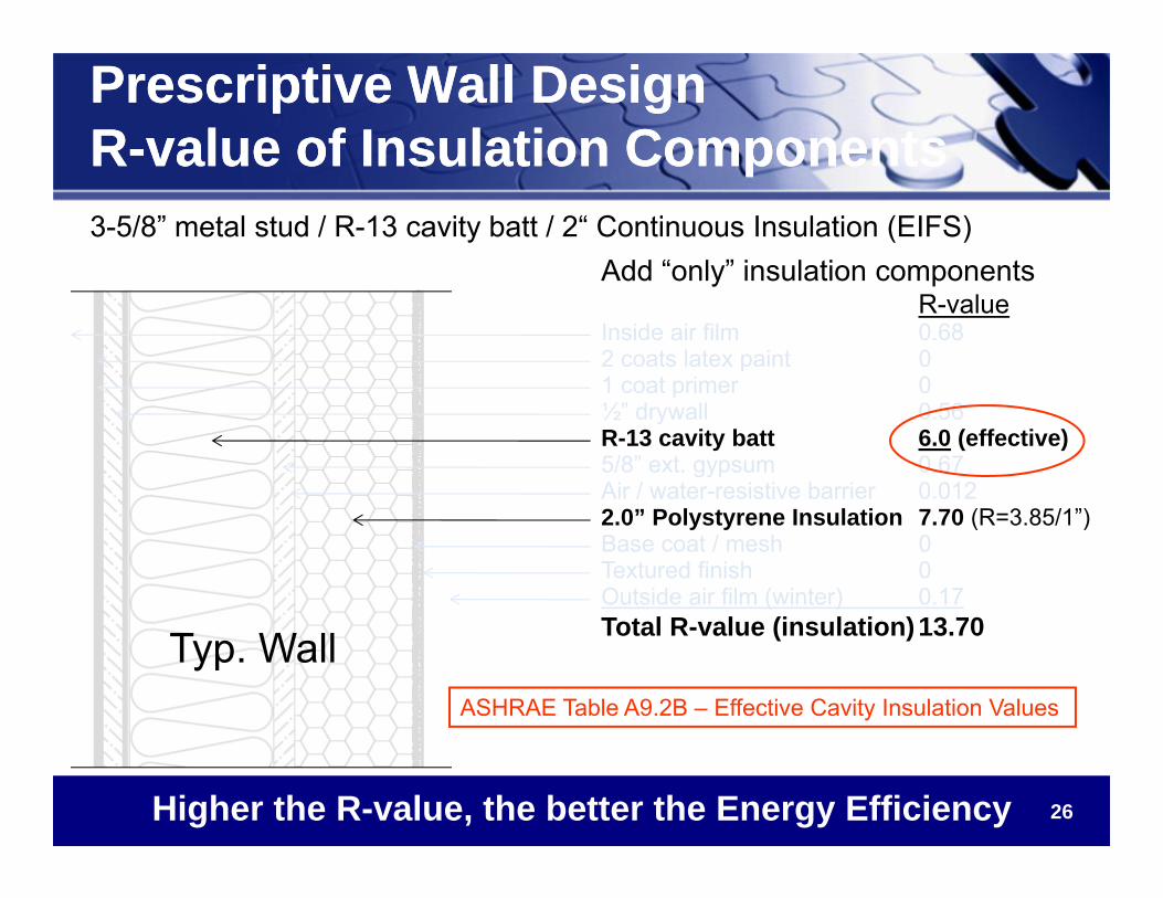
Prescriptive Wall DesignR-value of Insulation ComponentsPrescriptive Wall DesignR-value of Insulation Components3-5/8” metal stud / R-13 cavity batt / 2“ Continuous Insulation (EIFS)
Add “only” insulation componentsR-value
Inside air film 0.682 coats latex paint 01 coat primer 0½” drywall 0.56R-13 cavity batt 6.0 (effective)5/8” ext. gypsum 0.67Air / water-resistive barrier 0.0122.0” Polystyrene Insulation 7.70 (R=3.85/1”)Base coat / mesh 0Textured finish 0Outside air film (winter) 0.17Total R-value (insulation)13.70 Typ. Wall
Higher the R-value, the better the Energy Efficiency
ASHRAE Table A9.2B – Effective Cavity Insulation Values
27
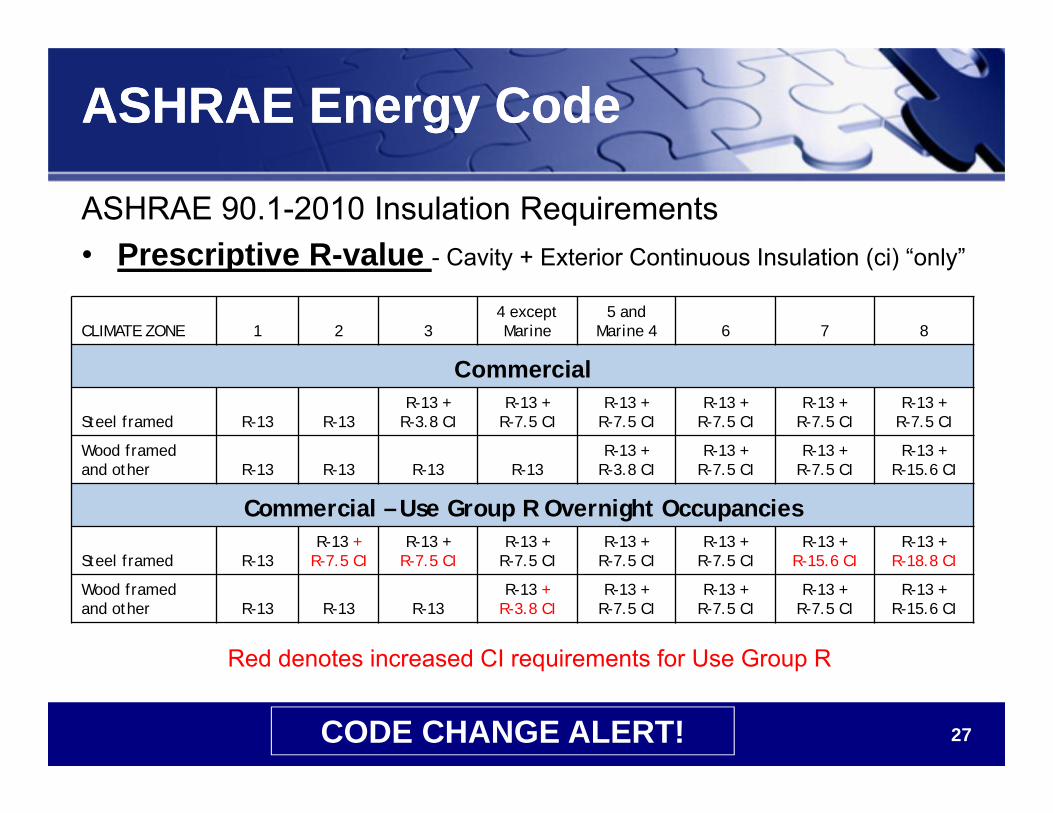
ASHRAE Energy CodeASHRAE Energy Code
ASHRAE 90.1-2010 Insulation Requirements• Prescriptive R-value - Cavity + Exterior Continuous Insulation (ci) “only”
CLIMATE ZONE 1 2 34 except Marine
5 and Marine 4 6 7 8
Commercial
Steel framed R-13 R-13R-13 +
R-3.8 CIR-13 +
R-7.5 CIR-13 +
R-7.5 CIR-13 +
R-7.5 CIR-13 +
R-7.5 CIR-13 +
R-7.5 CI
Wood framed and other R-13 R-13 R-13 R-13
R-13 +R-3.8 CI
R-13 +R-7.5 CI
R-13 +R-7.5 CI
R-13 +R-15.6 CI
Commercial – Use Group R Overnight Occupancies
Steel framed R-13R-13 +
R-7.5 CIR-13 +
R-7.5 CIR-13 +
R-7.5 CIR-13 +
R-7.5 CIR-13 +
R-7.5 CIR-13 +
R-15.6 CIR-13 +
R-18.8 CI
Wood framed and other R-13 R-13 R-13
R-13 +R-3.8 CI
R-13 +R-7.5 CI
R-13 +R-7.5 CI
R-13 +R-7.5 CI
R-13 +R-15.6 CI
Red denotes increased CI requirements for Use Group R
CODE CHANGE ALERT!
28
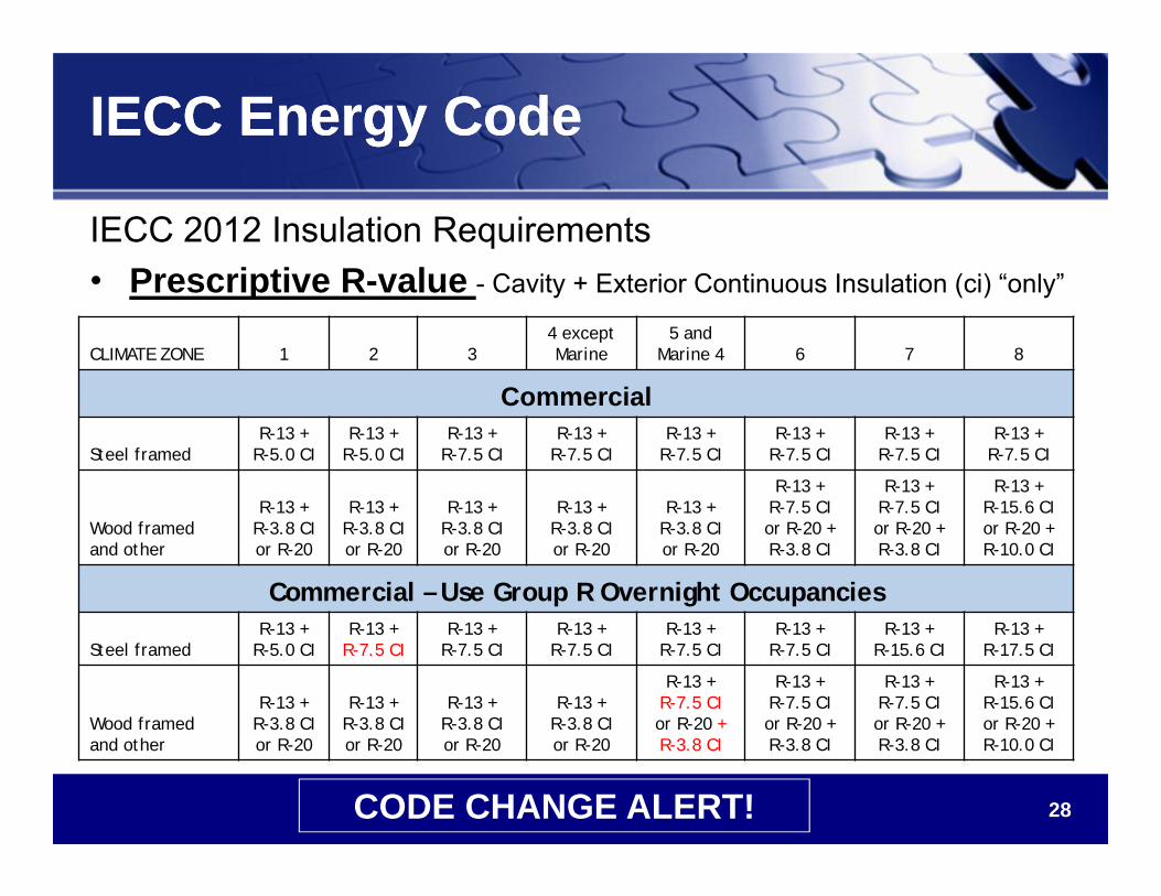
IECC Energy CodeIECC Energy Code
IECC 2012 Insulation Requirements• Prescriptive R-value - Cavity + Exterior Continuous Insulation (ci) “only”
CLIMATE ZONE 1 2 34 except Marine
5 and Marine 4 6 7 8
Commercial
Steel framedR-13 +
R-5.0 CIR-13 +
R-5.0 CIR-13 +
R-7.5 CIR-13 +
R-7.5 CIR-13 +
R-7.5 CIR-13 +
R-7.5 CIR-13 +
R-7.5 CIR-13 +
R-7.5 CI
Wood framed and other
R-13 +R-3.8 CIor R-20
R-13 +R-3.8 CIor R-20
R-13 +R-3.8 CIor R-20
R-13 +R-3.8 CIor R-20
R-13 +R-3.8 CIor R-20
R-13 +R-7.5 CIor R-20 + R-3.8 CI
R-13 +R-7.5 CIor R-20 + R-3.8 CI
R-13 +R-15.6 CIor R-20 + R-10.0 CI
Commercial – Use Group R Overnight Occupancies
Steel framedR-13 +
R-5.0 CIR-13 +
R-7.5 CIR-13 +
R-7.5 CIR-13 +
R-7.5 CIR-13 +
R-7.5 CIR-13 +
R-7.5 CIR-13 +
R-15.6 CIR-13 +
R-17.5 CI
Wood framed and other
R-13 +R-3.8 CIor R-20
R-13 +R-3.8 CIor R-20
R-13 +R-3.8 CIor R-20
R-13 +R-3.8 CIor R-20
R-13 +R-7.5 CIor R-20 + R-3.8 CI
R-13 +R-7.5 CIor R-20 + R-3.8 CI
R-13 +R-7.5 CIor R-20 + R-3.8 CI
R-13 +R-15.6 CIor R-20 + R-10.0 CI
CODE CHANGE ALERT!
29
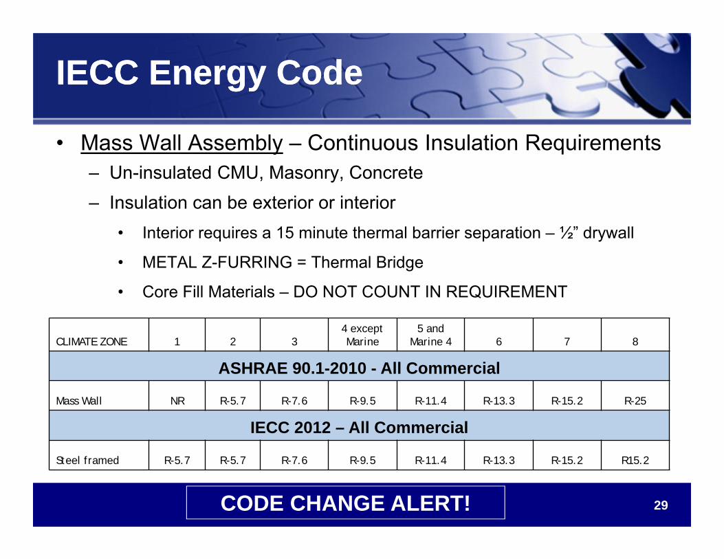
IECC Energy CodeIECC Energy Code
• Mass Wall Assembly – Continuous Insulation Requirements– Un-insulated CMU, Masonry, Concrete– Insulation can be exterior or interior
• Interior requires a 15 minute thermal barrier separation – ½” drywall
• METAL Z-FURRING = Thermal Bridge
• Core Fill Materials – DO NOT COUNT IN REQUIREMENT
CLIMATE ZONE 1 2 34 except Marine
5 and Marine 4 6 7 8
ASHRAE 90.1-2010 - All Commercial
Mass Wall NR R-5.7 R-7.6 R-9.5 R-11.4 R-13.3 R-15.2 R-25
IECC 2012 – All Commercial
Steel framed R-5.7 R-5.7 R-7.6 R-9.5 R-11.4 R-13.3 R-15.2 R15.2
CODE CHANGE ALERT!
30
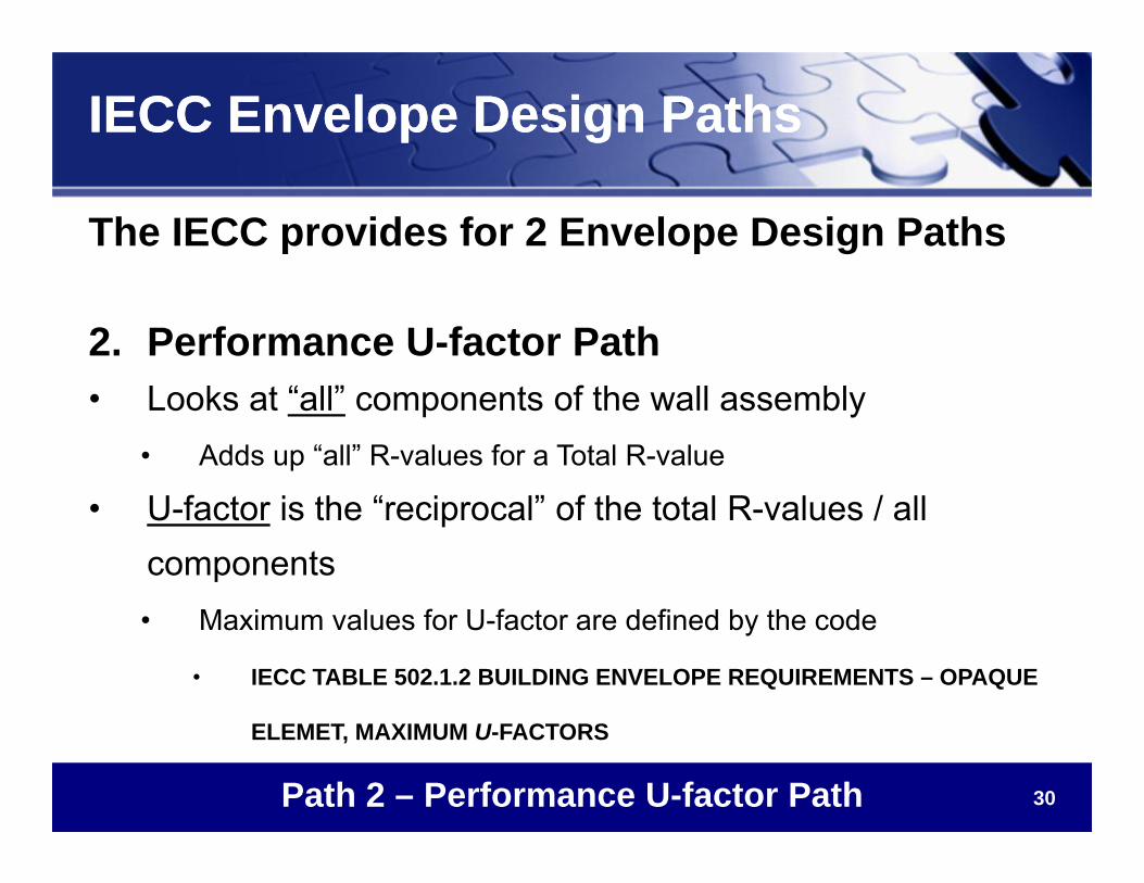
IECC Envelope Design PathsIECC Envelope Design Paths
The IECC provides for 2 Envelope Design Paths
2. Performance U-factor Path• Looks at “all” components of the wall assembly
• Adds up “all” R-values for a Total R-value
• U-factor is the “reciprocal” of the total R-values / all components• Maximum values for U-factor are defined by the code
• IECC TABLE 502.1.2 BUILDING ENVELOPE REQUIREMENTS – OPAQUE
ELEMET, MAXIMUM U-FACTORS
Path 2 – Performance U-factor Path
31
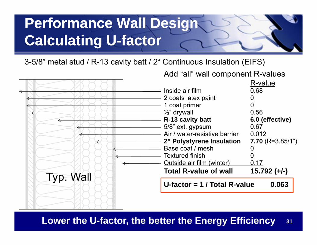
Performance Wall DesignCalculating U-factorPerformance Wall DesignCalculating U-factor3-5/8” metal stud / R-13 cavity batt / 2“ Continuous Insulation (EIFS)
Add “all” wall component R-valuesR-value
Inside air film 0.682 coats latex paint 01 coat primer 0½” drywall 0.56R-13 cavity batt 6.0 (effective)5/8” ext. gypsum 0.67Air / water-resistive barrier 0.0122” Polystyrene Insulation 7.70 (R=3.85/1”)Base coat / mesh 0Textured finish 0Outside air film (winter) 0.17Total R-value of wall 15.792 (+/-)
U-factor = 1 / Total R-value 0.063
Lower the U-factor, the better the Energy Efficiency
Typ. Wall
32
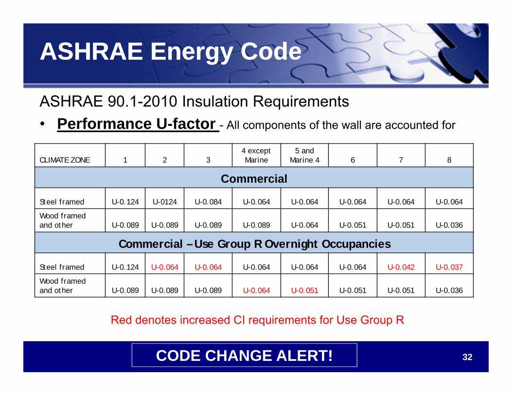
ASHRAE Energy CodeASHRAE Energy Code
ASHRAE 90.1-2010 Insulation Requirements• Performance U-factor - All components of the wall are accounted for
CLIMATE ZONE 1 2 34 except Marine
5 and Marine 4 6 7 8
Commercial
Steel framed U-0.124 U-0124 U-0.084 U-0.064 U-0.064 U-0.064 U-0.064 U-0.064
Wood framed and other U-0.089 U-0.089 U-0.089 U-0.089 U-0.064 U-0.051 U-0.051 U-0.036
Commercial – Use Group R Overnight Occupancies
Steel framed U-0.124 U-0.064 U-0.064 U-0.064 U-0.064 U-0.064 U-0.042 U-0.037
Wood framed and other U-0.089 U-0.089 U-0.089 U-0.064 U-0.051 U-0.051 U-0.051 U-0.036
Red denotes increased CI requirements for Use Group R
CODE CHANGE ALERT!
33 33
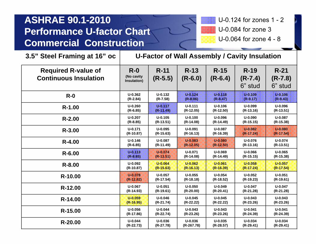
ASHRAE 90.1-2010Performance U-factor ChartCommercial Construction
ASHRAE 90.1-2010Performance U-factor ChartCommercial Construction3.5” Steel Framing at 16” oc U-Factor of Wall Assembly / Cavity Insulation
Required R-value ofContinuous Insulation
R-0(No cavityInsulation)
R-11(R-5.5)
R-13(R-6.0)
R-15(R-6.4)
R-19(R-7.4)6” stud
R-21(R-7.8)6” stud
R-0 U-0.362(R-2.84)
U-0.132(R-7.58)
U-0.124(R-8.06)
U-0.118(R-8.47)
U-0.109(R-9.17)
U-0.106(R-9.43)
R-1.00 U-0.260(R-6.85)
U-0.117(R-11.49)
U-0.111(R-12.05)
U-0.106(R-12.50)
U-0.099(R-13.16)
U-0.096(R-13.51)
R-2.00 U-0.207(R-8.85)
U-0.105(R-13.51)
U-0.100(R-14.08)
U-0.096(R-14.49)
U-0.090(R-15.15)
U-0.087(R-15.38)
R-3.00 U-0.171(R-10.87)
U-0.095(R-15.63)
U-0.091(R-16.13)
U-0.087(R-16.39)
U-0.082(R-17.24)
U-0.080(R-17.54)
R-4.00 U-0.146(R-6.85)
U-0.087(R-11.49)
U-0.083(R-12.05)
U-0.080(R-12.50)
U-0.076(R-13.16)
U-0.074(R-13.51)
R-6.00 U-0.113(R-8.85)
U-0.074(R-13.51)
U-0.071(R-14.08)
U-0.069(R-14.49)
U-0.066(R-15.15)
U-0.065(R-15.38)
R-8.00 U-0.092(R-10.87)
U-0.064(R-15.63)
U-0.062(R-16.13)
U-0.061(R-16.39)
U-0.058(R-17.24)
U-0.057(R-17.54)
R-10.00 U-0.078(R-12.82)
U-0.057(R-17.54)
U-0.055(R-18.18)
U-0.054(R-18.52)
U-0.052(R-19.23)
U-0.051(R-19.61)
R-12.00 U-0.067(R-14.93)
U-0.051(R-19.61)
U-0.050(R-20.00)
U-0.049(R-20.41)
U-0.047(R-21.28)
U-0.047(R-21.28)
R-14.00 U-0.059(R-16.95)
U-0.046(R-21.74)
U-0.045(R-22.22)
U-0.045(R-22.22)
U-0.043(R-23.26)
U-0.043(R-23.26)
R-15.00 U-0.056(R-17.86)
U-0.044(R-22.74)
U-0.043(R-23.26)
U-0.043(R-23.26)
U-0.041(R-24.39)
U-0.041(R-24.39)
R-20.00 U-0.044(R-22.73)
U-0.036(R-27.78)
U-0.036(R-267.78)
U-0.035(R-28.57)
U-0.034(R-29.41)
U-0.034(R-29.41)
U-0.077 for zones 1 - 4
U-0.055 for zones 5 - 8
U-0.124 for zones 1 - 2
U-0.064 for zone 4 - 8U-0.084 for zone 3
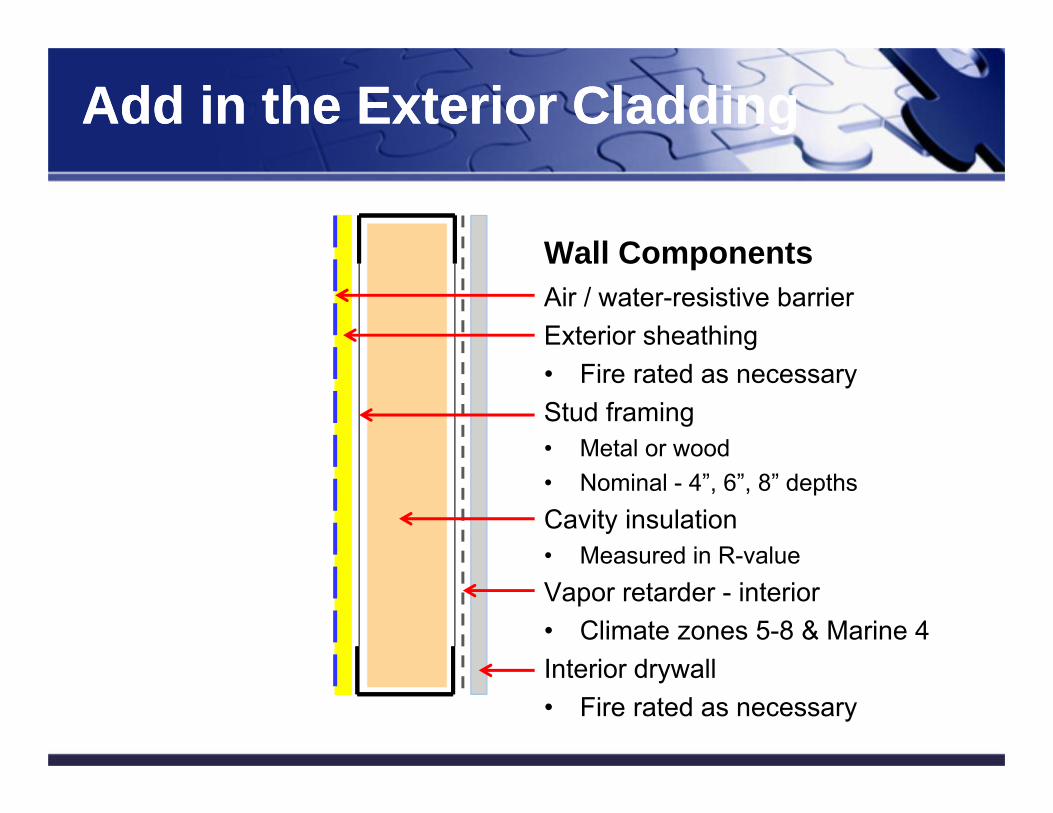
Wall ComponentsAir / water-resistive barrierExterior sheathing• Fire rated as necessaryStud framing• Metal or wood• Nominal - 4”, 6”, 8” depthsCavity insulation• Measured in R-valueVapor retarder - interior• Climate zones 5-8 & Marine 4Interior drywall • Fire rated as necessary
34
Add in the Exterior CladdingAdd in the Exterior Cladding
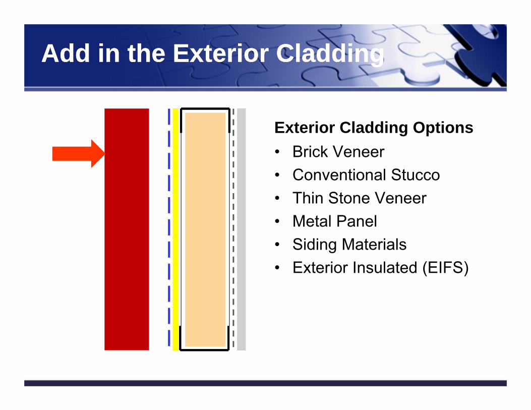
Exterior Cladding Options• Brick Veneer• Conventional Stucco• Thin Stone Veneer• Metal Panel• Siding Materials• Exterior Insulated (EIFS)
35
Add in the Exterior CladdingAdd in the Exterior Cladding
Add in Continuous Insulation (CI)Add in Continuous Insulation (CI)
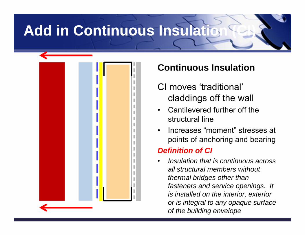
Continuous Insulation
CI moves ‘traditional’ claddings off the wall
• Cantilevered further off the structural line
• Increases “moment” stresses at points of anchoring and bearing
Definition of CI• Insulation that is continuous across
all structural members without thermal bridges other than fasteners and service openings. It is installed on the interior, exterior or is integral to any opaque surface of the building envelope
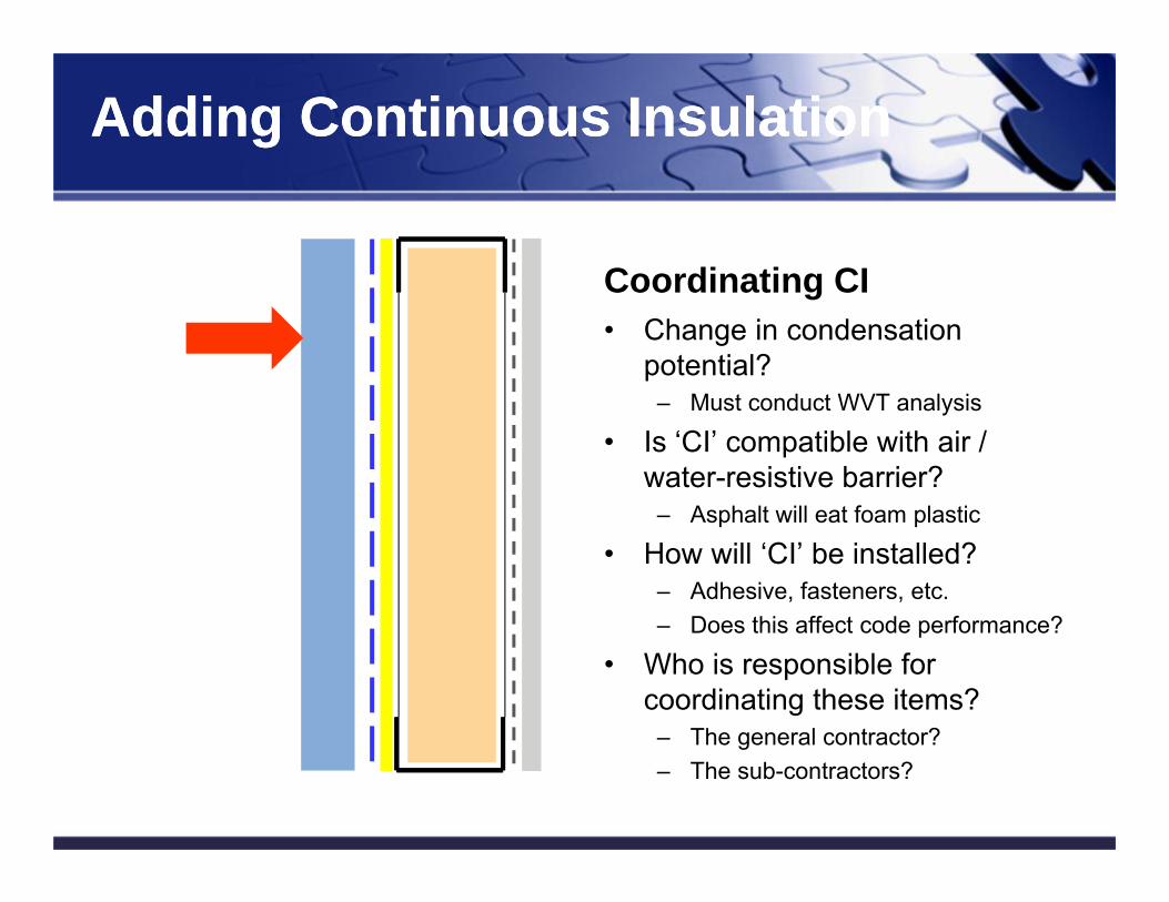
Coordinating CI• Change in condensation
potential?– Must conduct WVT analysis
• Is ‘CI’ compatible with air / water-resistive barrier?
– Asphalt will eat foam plastic
• How will ‘CI’ be installed?– Adhesive, fasteners, etc.– Does this affect code performance?
• Who is responsible for coordinating these items?
– The general contractor?– The sub-contractors?
37
Adding Continuous InsulationAdding Continuous Insulation
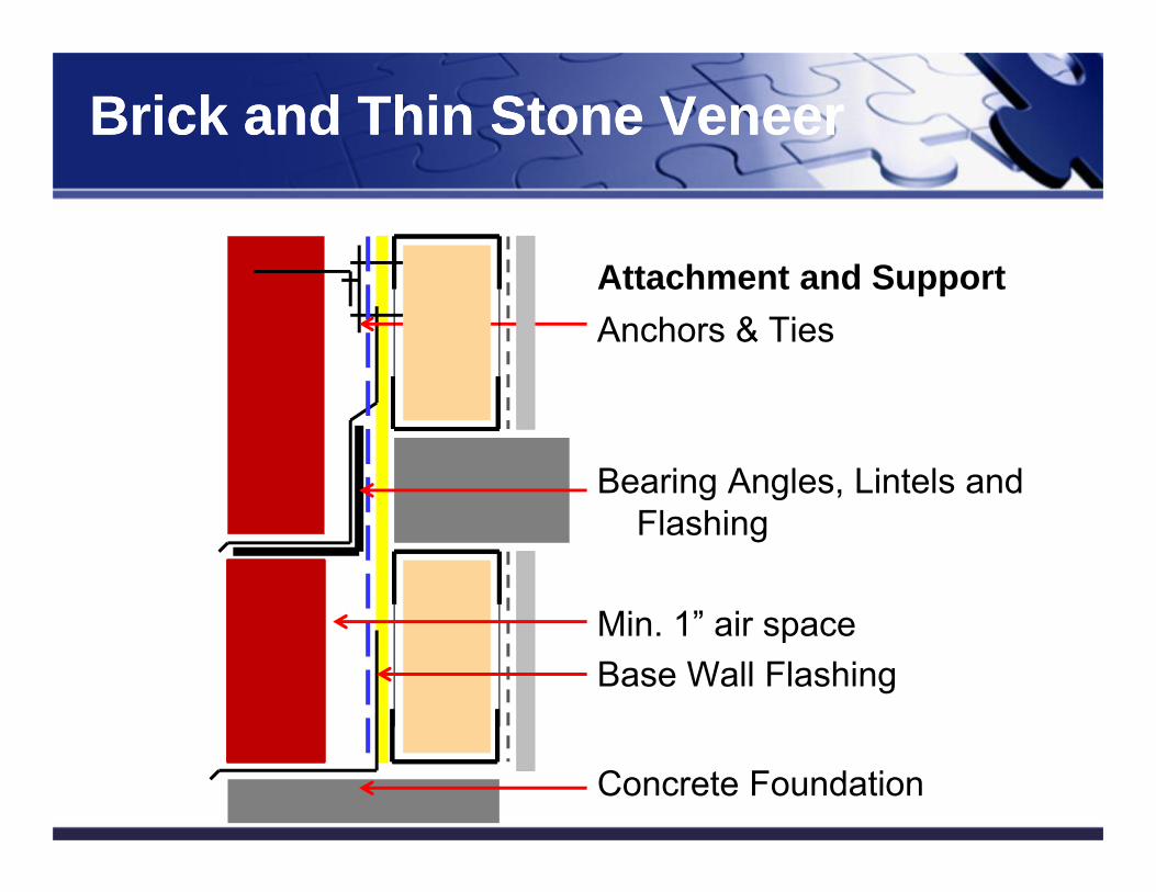
Attachment and SupportAnchors & Ties
Bearing Angles, Lintels and Flashing
Min. 1” air spaceBase Wall Flashing
Concrete Foundation38
Brick and Thin Stone VeneerBrick and Thin Stone Veneer
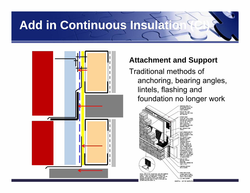
Attachment and SupportTraditional methods of
anchoring, bearing angles, lintels, flashing and foundation no longer work
39
Add in Continuous Insulation (CI)Add in Continuous Insulation (CI)
Add in Continuous Insulation (CI)Add in Continuous Insulation (CI)
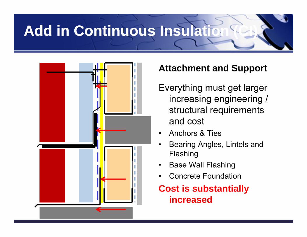
Attachment and Support
Everything must get larger increasing engineering / structural requirements and cost
• Anchors & Ties• Bearing Angles, Lintels and
Flashing• Base Wall Flashing• Concrete Foundation
Cost is substantially increased
Add in Continuous Insulation (CI)Add in Continuous Insulation (CI)
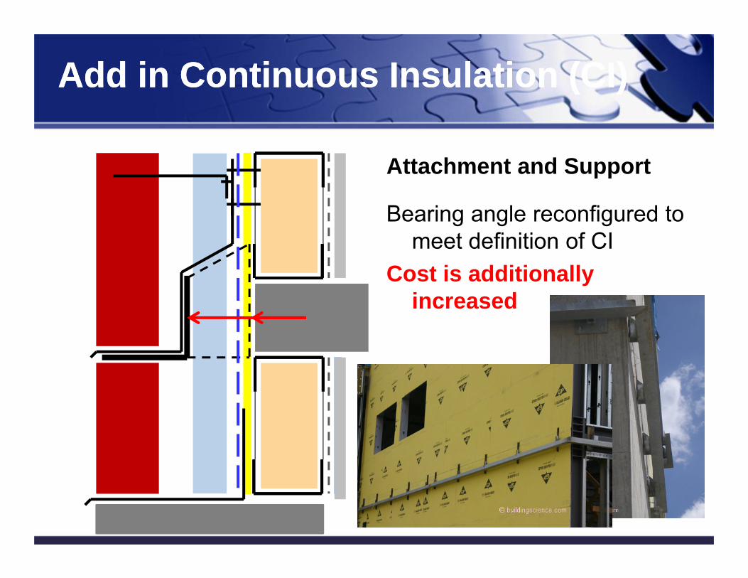
Attachment and Support
Bearing angle reconfigured to meet definition of CI
Cost is additionally increased
Stucco & Siding Stucco & Siding
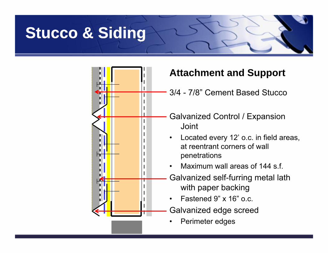
Attachment and Support
3/4 - 7/8” Cement Based Stucco
Galvanized Control / Expansion Joint
• Located every 12’ o.c. in field areas, at reentrant corners of wall penetrations
• Maximum wall areas of 144 s.f.Galvanized self-furring metal lath
with paper backing• Fastened 9” x 16” o.c.Galvanized edge screed• Perimeter edges
Add in Continuous Insulation (CI)Add in Continuous Insulation (CI)
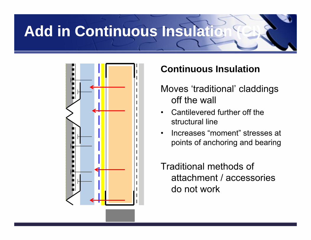
Continuous Insulation
Moves ‘traditional’ claddings off the wall
• Cantilevered further off the structural line
• Increases “moment” stresses at points of anchoring and bearing
Traditional methods of attachment / accessories do not work
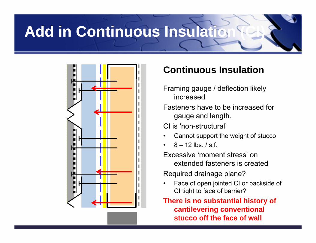
Continuous Insulation
Framing gauge / deflection likely increased
Fasteners have to be increased for gauge and length.
CI is ‘non-structural’• Cannot support the weight of stucco• 8 – 12 lbs. / s.f.Excessive ‘moment stress’ on
extended fasteners is createdRequired drainage plane? • Face of open jointed CI or backside of
CI tight to face of barrier?There is no substantial history of
cantilevering conventional stucco off the face of wall
Add in Continuous Insulation (CI)Add in Continuous Insulation (CI)
Brick and Thin Stone Veneer w/ CIBrick and Thin Stone Veneer w/ CI
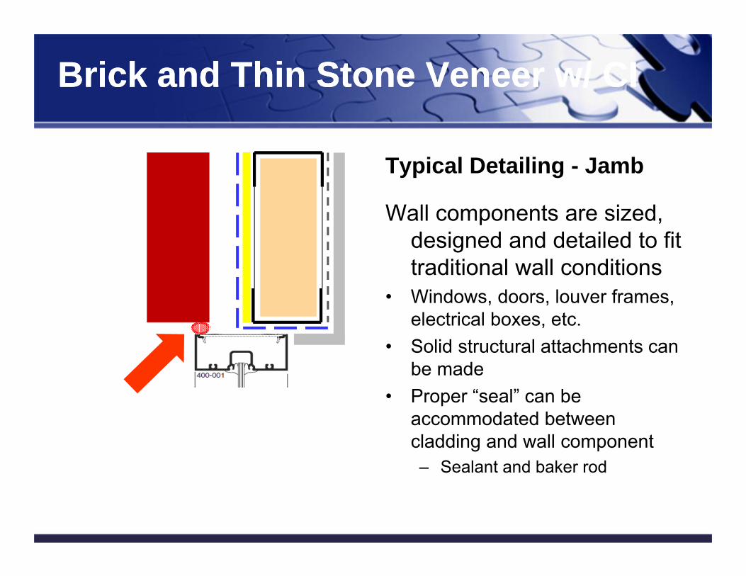
Typical Detailing - Jamb
Wall components are sized, designed and detailed to fit traditional wall conditions
• Windows, doors, louver frames, electrical boxes, etc.
• Solid structural attachments can be made
• Proper “seal” can be accommodated between cladding and wall component– Sealant and baker rod
Add in Continuous Insulation (CI)Add in Continuous Insulation (CI)
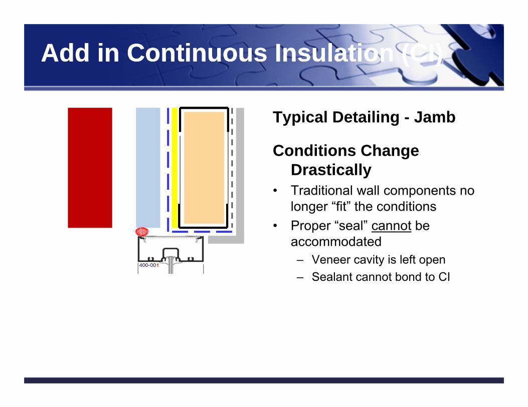
Typical Detailing - Jamb
Conditions Change Drastically
• Traditional wall components no longer “fit” the conditions
• Proper “seal” cannot be accommodated– Veneer cavity is left open– Sealant cannot bond to CI
Add in Continuous Insulation (CI)Add in Continuous Insulation (CI)
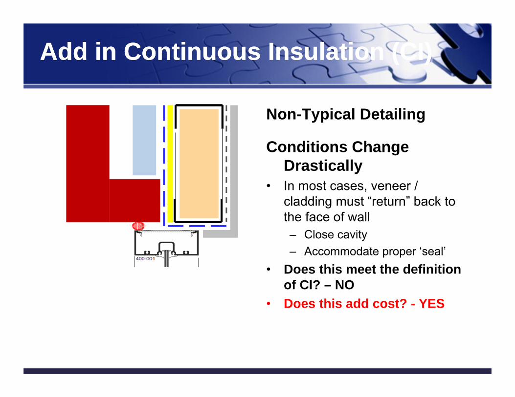
Non-Typical Detailing
Conditions Change Drastically
• In most cases, veneer / cladding must “return” back to the face of wall– Close cavity– Accommodate proper ‘seal’
• Does this meet the definition of CI? – NO
• Does this add cost? - YES
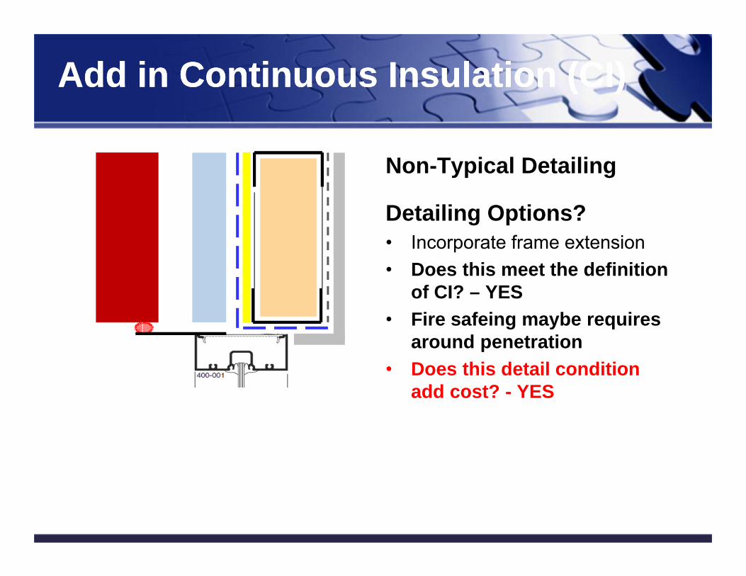
Add in Continuous Insulation (CI)Add in Continuous Insulation (CI)
Detailing Options?• Incorporate frame extension• Does this meet the definition
of CI? – YES• Fire safeing maybe requires
around penetration• Does this detail condition
add cost? - YES
Non-Typical Detailing
Stucco & Siding Stucco & Siding
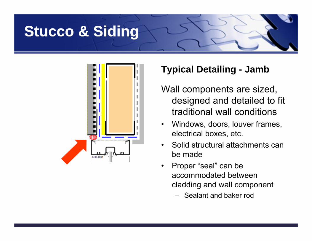
Typical Detailing - Jamb
Wall components are sized, designed and detailed to fit traditional wall conditions
• Windows, doors, louver frames, electrical boxes, etc.
• Solid structural attachments can be made
• Proper “seal” can be accommodated between cladding and wall component– Sealant and baker rod
Stucco & Siding Stucco & Siding
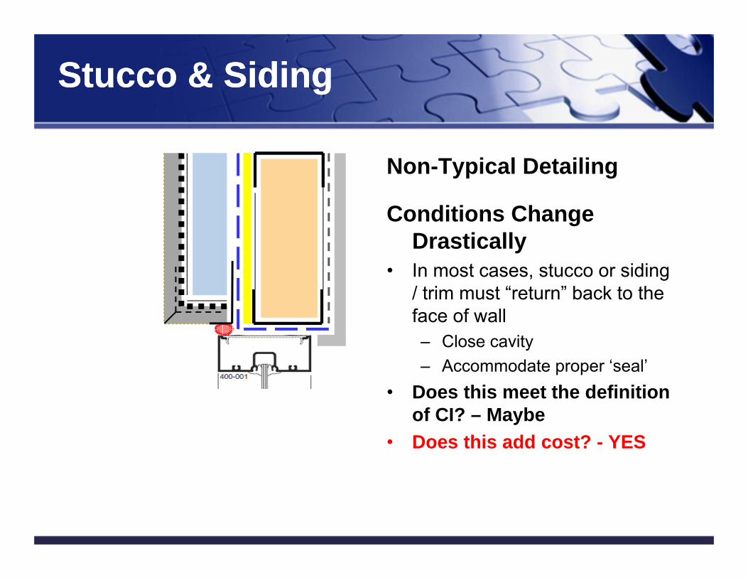
Non-Typical Detailing
Conditions Change Drastically
• In most cases, stucco or siding / trim must “return” back to the face of wall– Close cavity– Accommodate proper ‘seal’
• Does this meet the definition of CI? – Maybe
• Does this add cost? - YES
Add in Continuous Insulation (CI)Add in Continuous Insulation (CI)
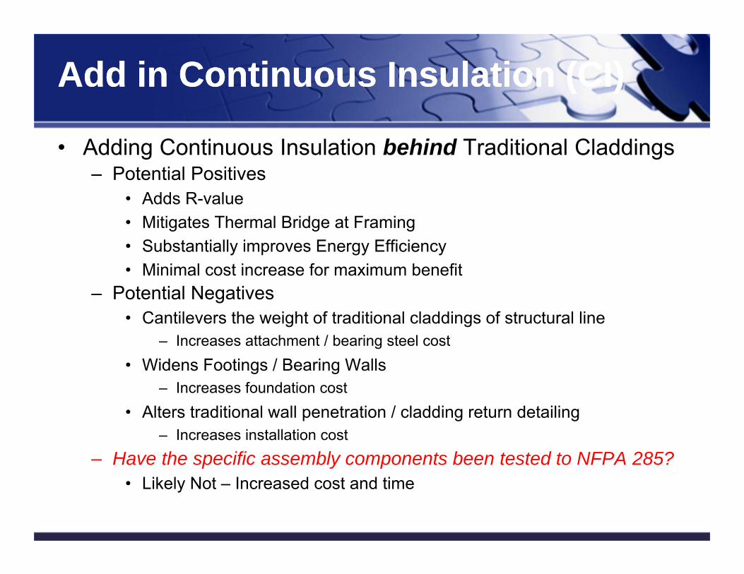
• Adding Continuous Insulation behind Traditional Claddings– Potential Positives
• Adds R-value• Mitigates Thermal Bridge at Framing• Substantially improves Energy Efficiency• Minimal cost increase for maximum benefit
– Potential Negatives• Cantilevers the weight of traditional claddings of structural line
– Increases attachment / bearing steel cost• Widens Footings / Bearing Walls
– Increases foundation cost• Alters traditional wall penetration / cladding return detailing
– Increases installation cost– Have the specific assembly components been tested to NFPA 285?
• Likely Not – Increased cost and time
51
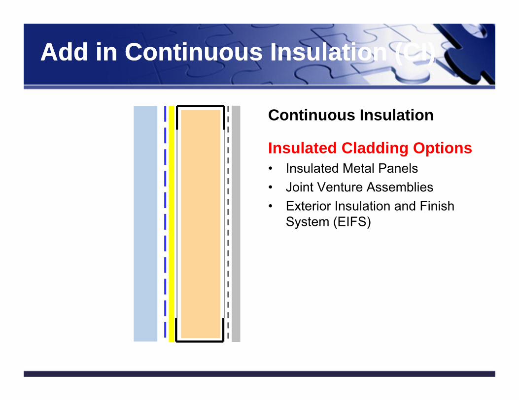
Add in Continuous Insulation (CI)Add in Continuous Insulation (CI)
Continuous Insulation
Insulated Cladding Options• Insulated Metal Panels• Joint Venture Assemblies• Exterior Insulation and Finish
System (EIFS)
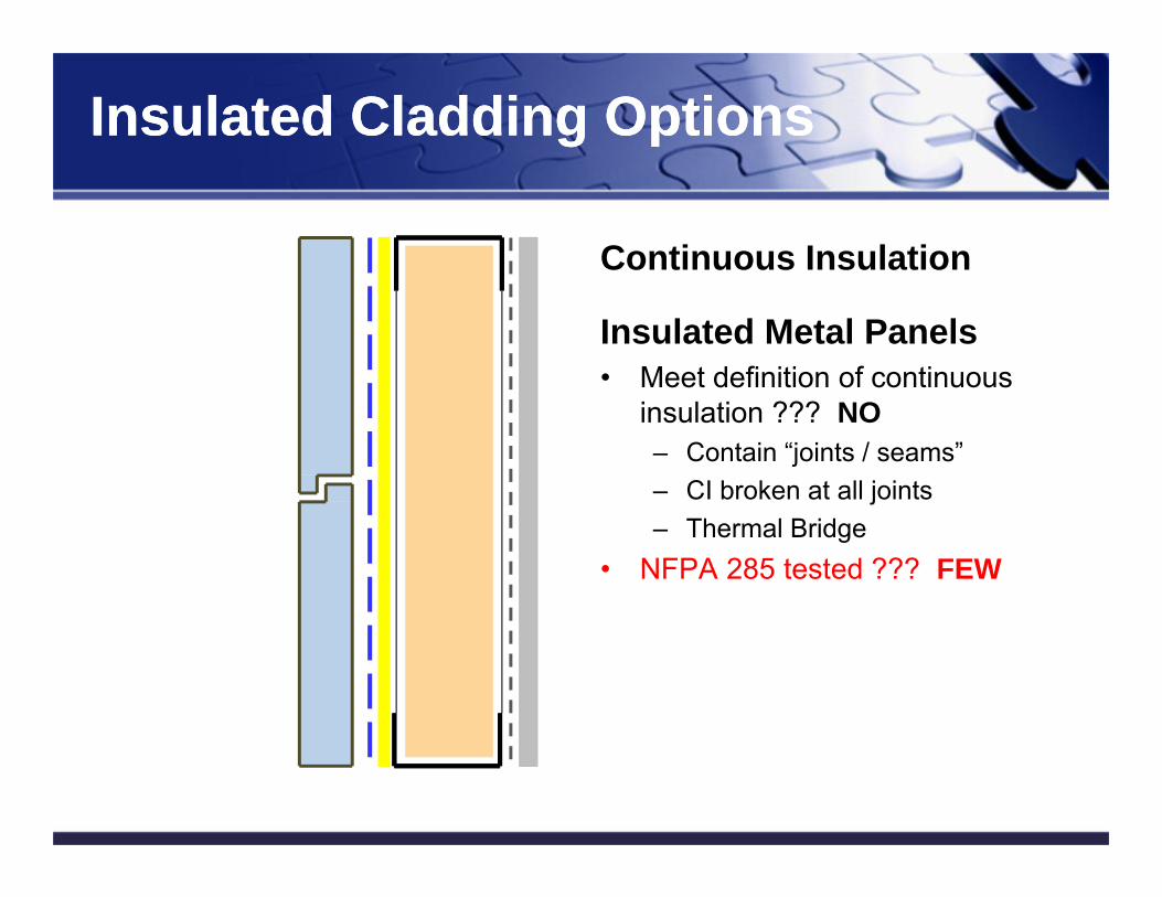
Insulated Cladding OptionsInsulated Cladding Options
Continuous Insulation
Insulated Metal Panels• Meet definition of continuous
insulation ??? NO– Contain “joints / seams”– CI broken at all joints– Thermal Bridge
• NFPA 285 tested ??? FEW
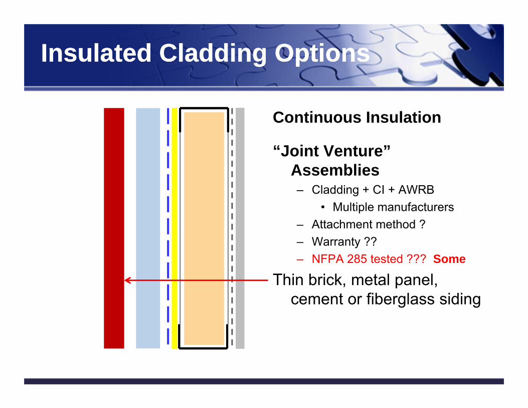
Insulated Cladding OptionsInsulated Cladding Options
Continuous Insulation
“Joint Venture” Assemblies– Cladding + CI + AWRB
• Multiple manufacturers– Attachment method ?– Warranty ??– NFPA 285 tested ??? Some
Thin brick, metal panel, cement or fiberglass siding
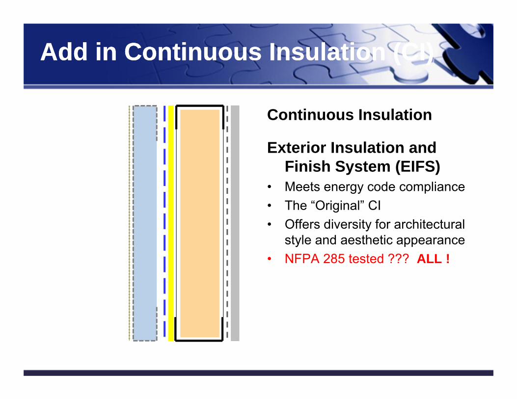
Add in Continuous Insulation (CI)Add in Continuous Insulation (CI)
Continuous Insulation
Exterior Insulation and Finish System (EIFS)
• Meets energy code compliance• The “Original” CI• Offers diversity for architectural
style and aesthetic appearance• NFPA 285 tested ??? ALL !
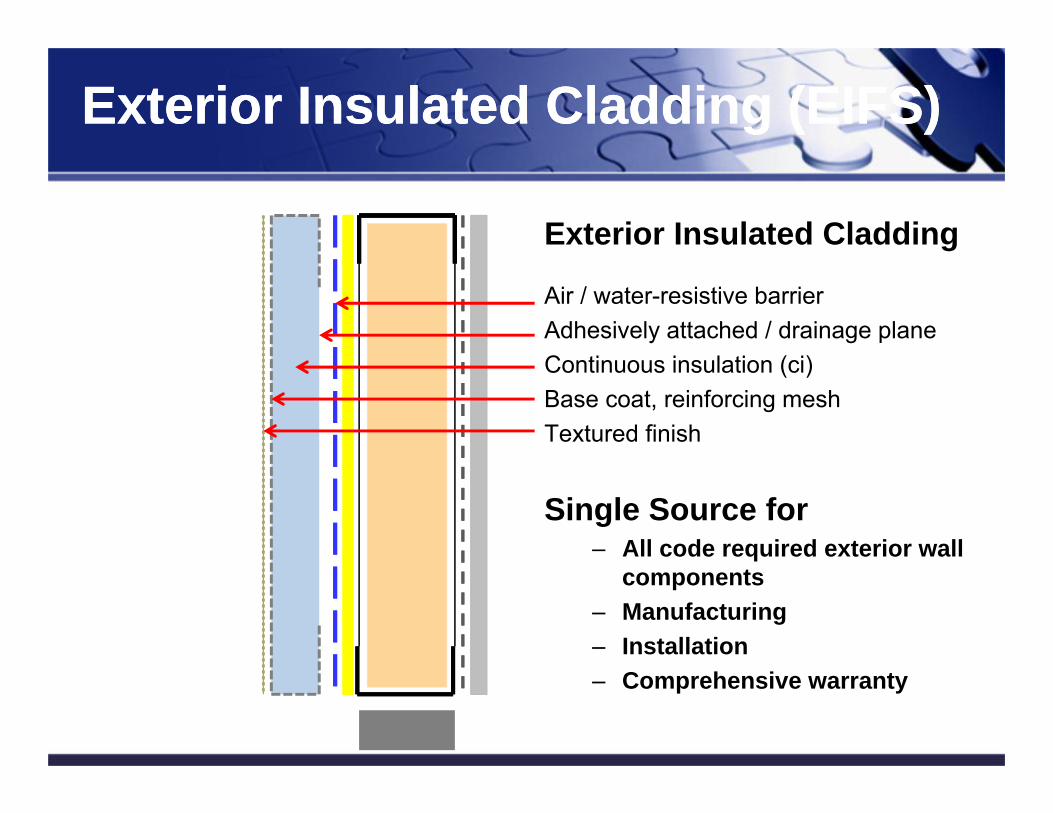
Exterior Insulated Cladding (EIFS)Exterior Insulated Cladding (EIFS)
Exterior Insulated Cladding
Air / water-resistive barrierAdhesively attached / drainage planeContinuous insulation (ci)Base coat, reinforcing meshTextured finish
Single Source for– All code required exterior wall
components– Manufacturing– Installation – Comprehensive warranty
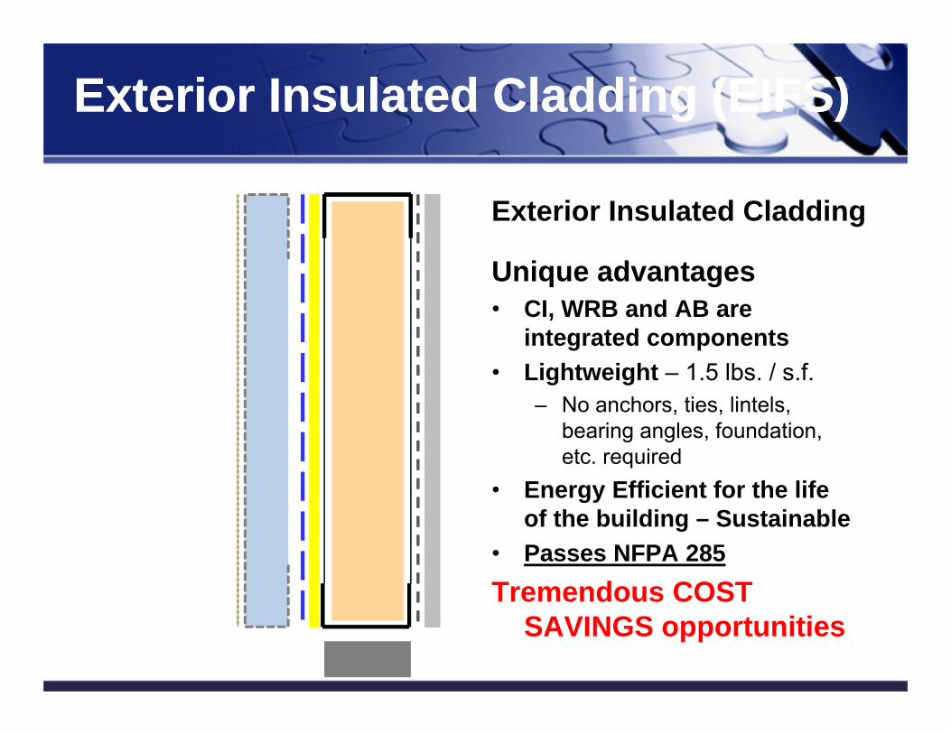
Exterior Insulated Cladding (EIFS)Exterior Insulated Cladding (EIFS)
Exterior Insulated Cladding
Unique advantages• CI, WRB and AB are
integrated components• Lightweight – 1.5 lbs. / s.f.
– No anchors, ties, lintels, bearing angles, foundation, etc. required
• Energy Efficient for the life of the building – Sustainable
• Passes NFPA 285Tremendous COST
SAVINGS opportunities
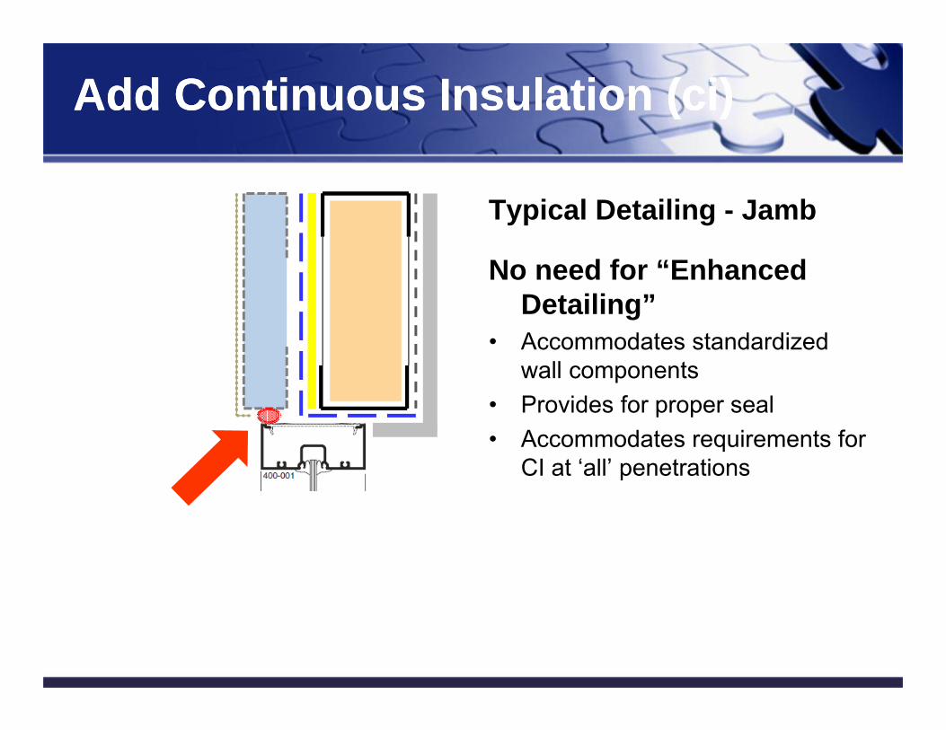
Add Continuous Insulation (ci)Add Continuous Insulation (ci)
Typical Detailing - Jamb
No need for “Enhanced Detailing”
• Accommodates standardized wall components
• Provides for proper seal• Accommodates requirements for
CI at ‘all’ penetrations
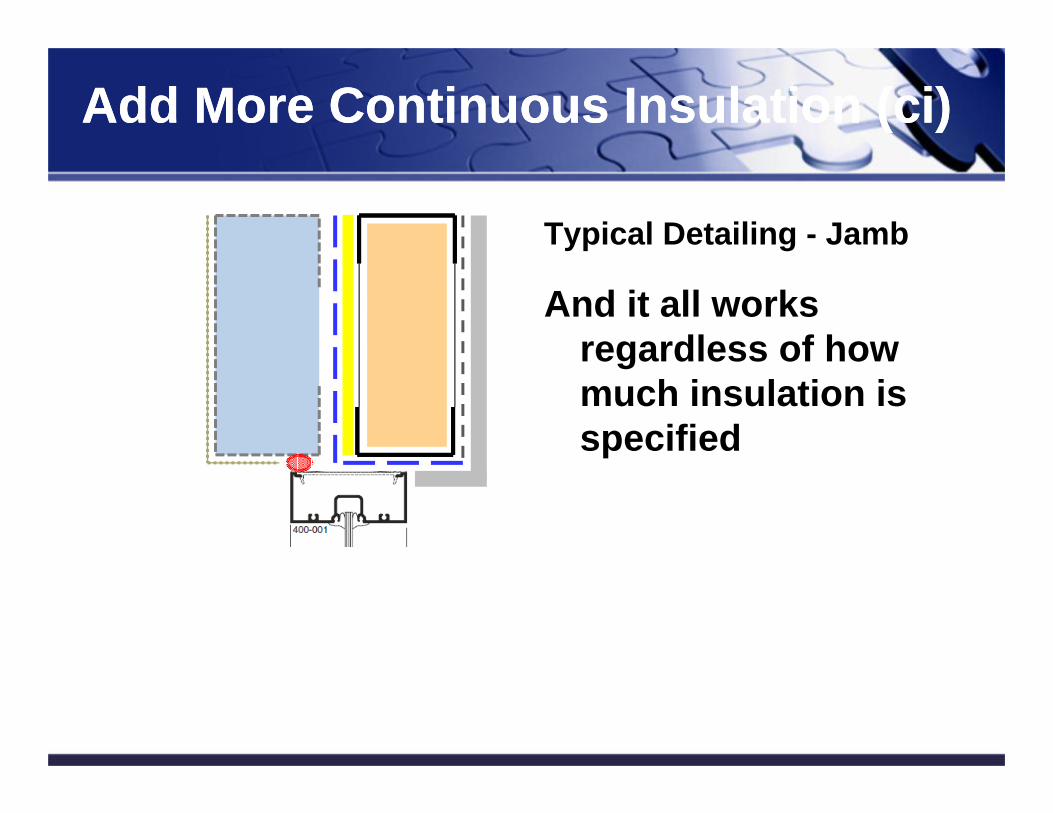
Add More Continuous Insulation (ci)Add More Continuous Insulation (ci)
Typical Detailing - Jamb
And it all works regardless of how much insulation is specified
Exterior Insulated Cladding (EIFS)Exterior Insulated Cladding (EIFS)
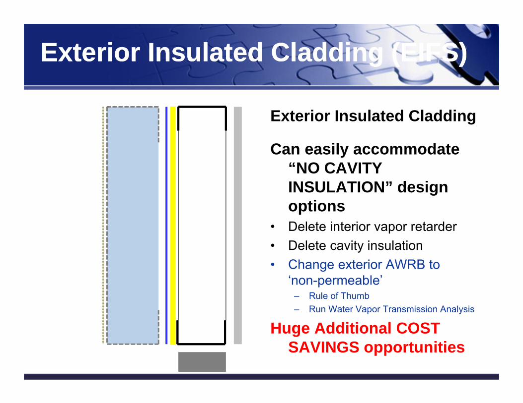
Exterior Insulated Cladding
Can easily accommodate “NO CAVITY INSULATION” design options
• Delete interior vapor retarder• Delete cavity insulation• Change exterior AWRB to
‘non-permeable’– Rule of Thumb– Run Water Vapor Transmission Analysis
Huge Additional COST SAVINGS opportunities
61
Insulated Claddings – EIFS with EPSInsulated Claddings – EIFS with EPS
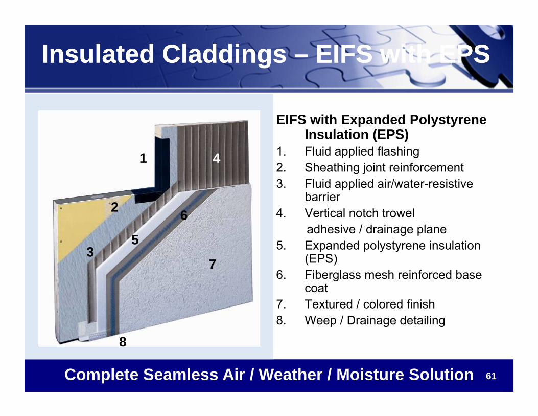
EIFS with Expanded Polystyrene Insulation (EPS)
1. Fluid applied flashing2. Sheathing joint reinforcement3. Fluid applied air/water-resistive
barrier4. Vertical notch trowel
adhesive / drainage plane5. Expanded polystyrene insulation
(EPS)6. Fiberglass mesh reinforced base
coat7. Textured / colored finish8. Weep / Drainage detailing
Complete Seamless Air / Weather / Moisture Solution
1
2
3
4
5
6
7
8
62
EIFS Insulation OptionsEPS or XPSEIFS Insulation OptionsEPS or XPS
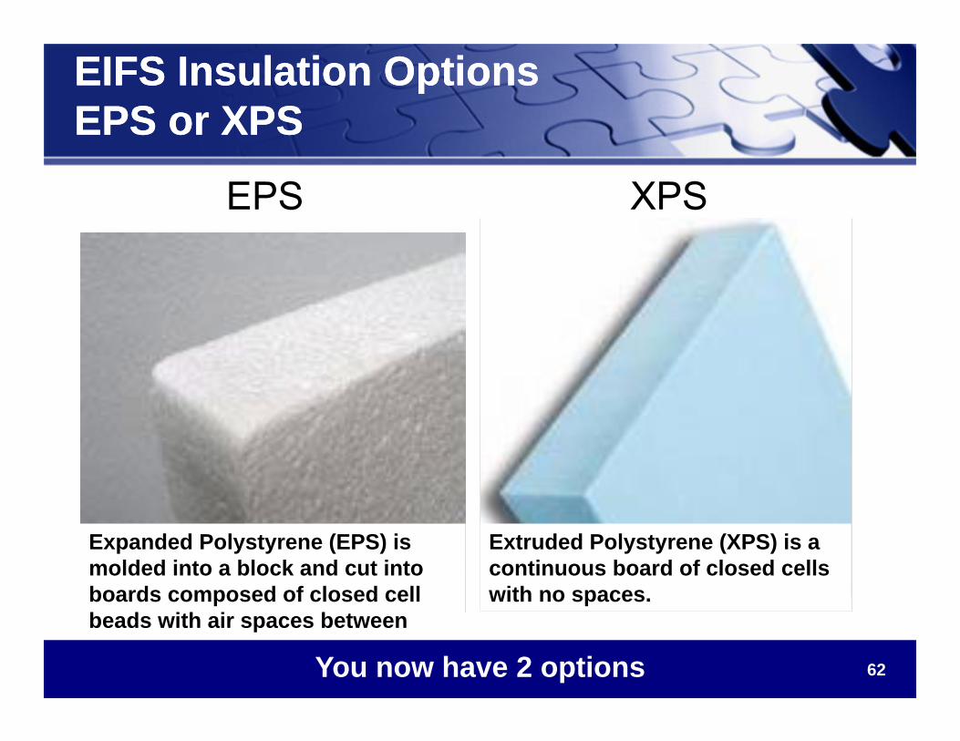
EPS XPS
Extruded Polystyrene (XPS) is a continuous board of closed cells with no spaces.
Expanded Polystyrene (EPS) is molded into a block and cut into boards composed of closed cell beads with air spaces between
You now have 2 options
63
Insulated Claddings – EIFS with XPSInsulated Claddings – EIFS with XPS
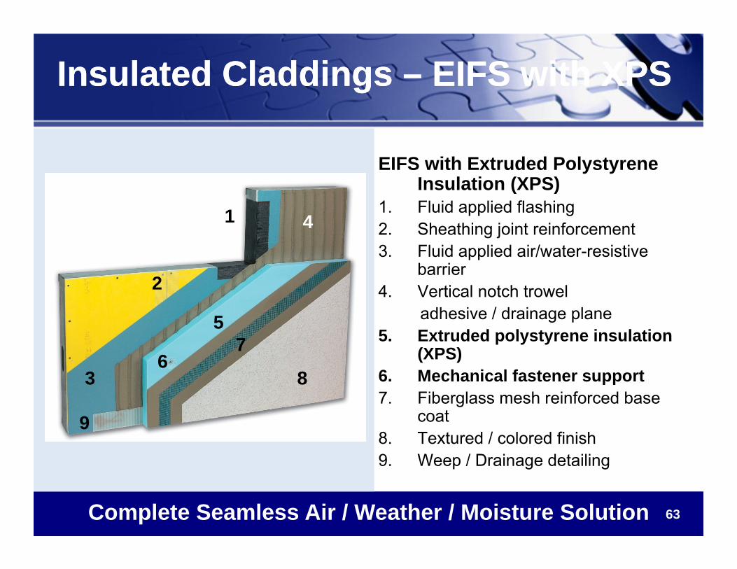
EIFS with Extruded Polystyrene Insulation (XPS)
1. Fluid applied flashing2. Sheathing joint reinforcement3. Fluid applied air/water-resistive
barrier4. Vertical notch trowel
adhesive / drainage plane5. Extruded polystyrene insulation
(XPS)6. Mechanical fastener support7. Fiberglass mesh reinforced base
coat8. Textured / colored finish9. Weep / Drainage detailing
Complete Seamless Air / Weather / Moisture Solution
1
2
3
4
5
68
9
7
64
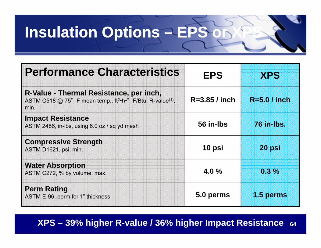
Insulation Options – EPS or XPSInsulation Options – EPS or XPS
Performance Characteristics EPS XPSR-Value - Thermal Resistance, per inch,ASTM C518 @ 75°F mean temp., ft2•h•°F/Btu, R-value(1), min.
R=3.85 / inch R=5.0 / inch
Impact ResistanceASTM 2486, in-lbs, using 6.0 oz / sq yd mesh 56 in-lbs 76 in-lbs.
Compressive StrengthASTM D1621, psi, min. 10 psi 20 psi
Water AbsorptionASTM C272, % by volume, max. 4.0 % 0.3 %
Perm RatingASTM E-96, perm for 1” thickness 5.0 perms 1.5 perms
XPS – 39% higher R-value / 36% higher Impact Resistance
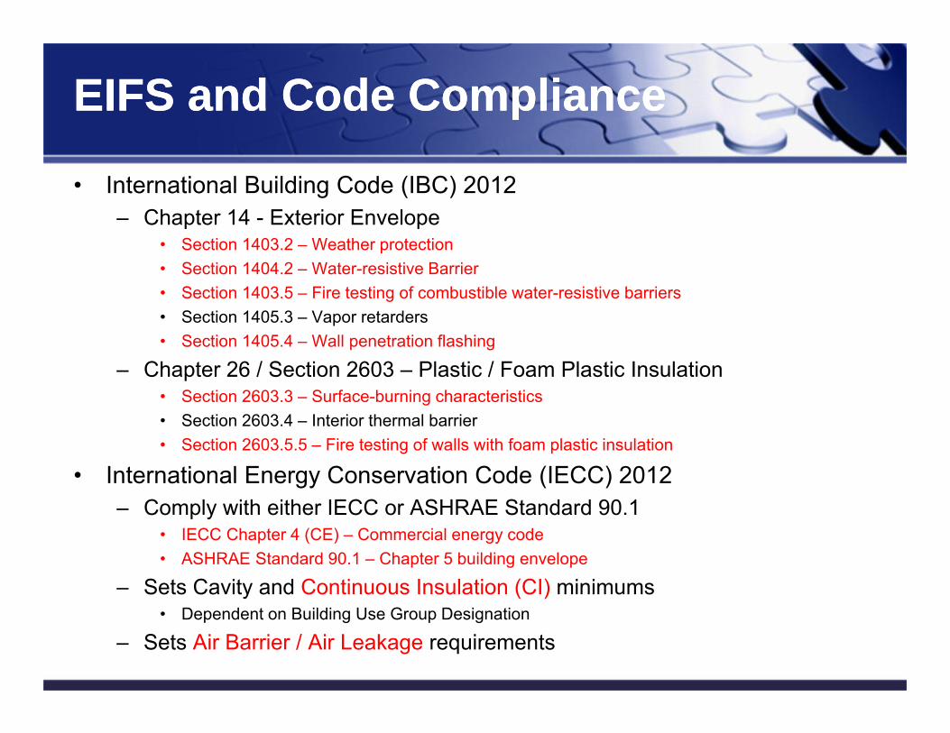
EIFS and Code ComplianceEIFS and Code Compliance
• International Building Code (IBC) 2012– Chapter 14 - Exterior Envelope
• Section 1403.2 – Weather protection• Section 1404.2 – Water-resistive Barrier• Section 1403.5 – Fire testing of combustible water-resistive barriers• Section 1405.3 – Vapor retarders• Section 1405.4 – Wall penetration flashing
– Chapter 26 / Section 2603 – Plastic / Foam Plastic Insulation• Section 2603.3 – Surface-burning characteristics• Section 2603.4 – Interior thermal barrier• Section 2603.5.5 – Fire testing of walls with foam plastic insulation
• International Energy Conservation Code (IECC) 2012– Comply with either IECC or ASHRAE Standard 90.1
• IECC Chapter 4 (CE) – Commercial energy code• ASHRAE Standard 90.1 – Chapter 5 building envelope
– Sets Cavity and Continuous Insulation (CI) minimums• Dependent on Building Use Group Designation
– Sets Air Barrier / Air Leakage requirements65
66
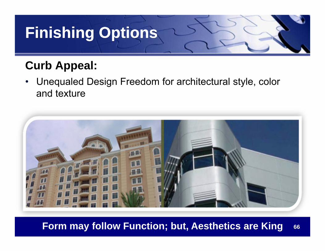
Finishing OptionsFinishing Options
Curb Appeal:• Unequaled Design Freedom for architectural style, color
and texture
Form may follow Function; but, Aesthetics are King
67
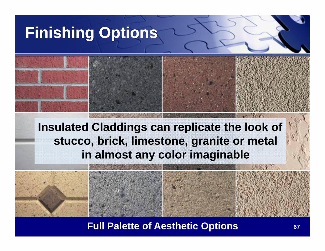
Finishing OptionsFinishing Options
Full Palette of Aesthetic Options
Insulated Claddings can replicate the look of stucco, brick, limestone, granite or metal
in almost any color imaginable
Insulated Claddings can replicate the look of stucco, brick, limestone, granite or metal
in almost any color imaginable
68
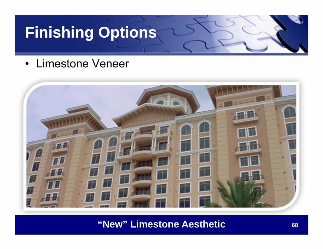
Finishing OptionsFinishing Options
• Limestone Veneer
“New” Limestone Aesthetic
69
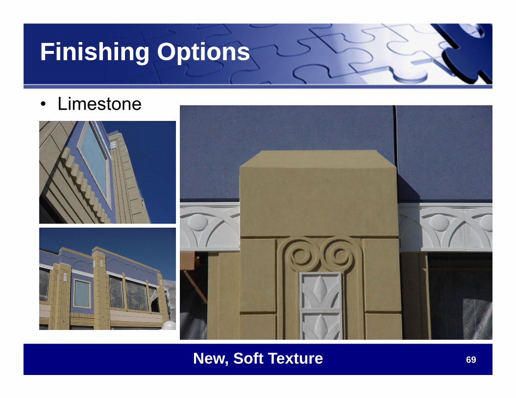
Finishing OptionsFinishing Options
New, Soft Texture
• Limestone
70
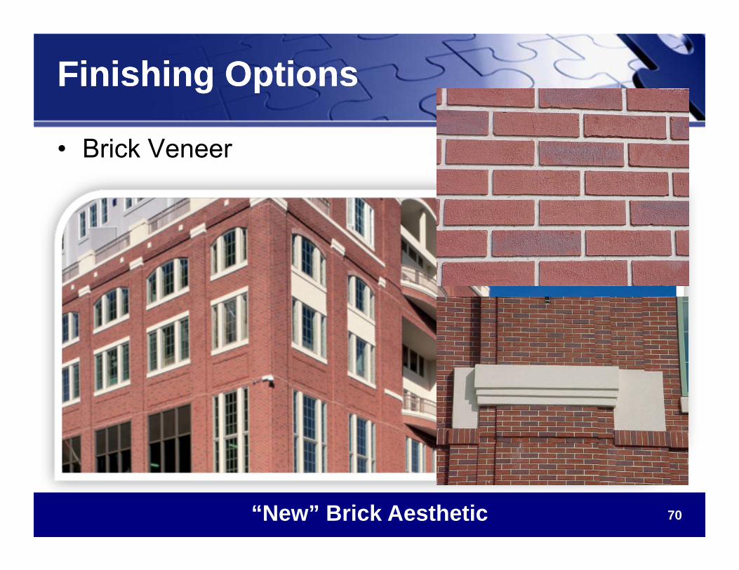
Finishing OptionsFinishing Options
• Brick Veneer
“New” Brick Aesthetic
71
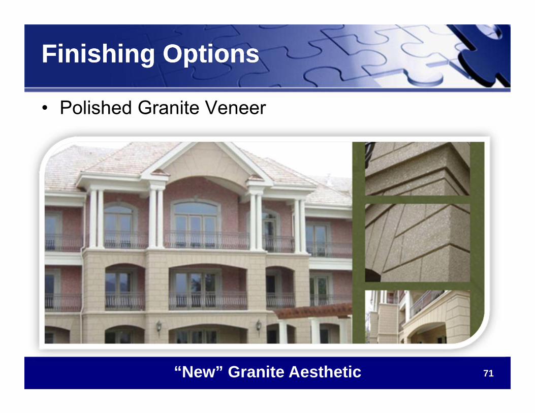
Finishing OptionsFinishing Options
• Polished Granite Veneer
“New” Granite Aesthetic
72
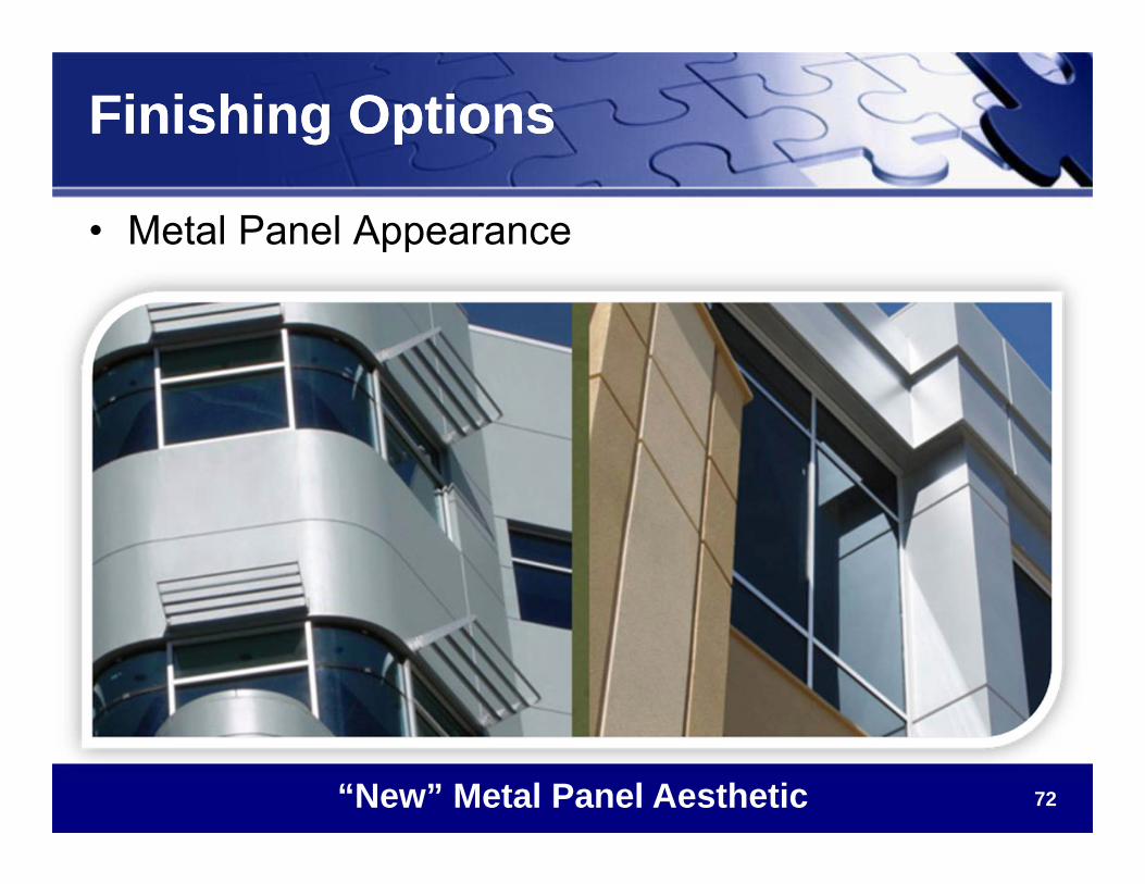
Finishing OptionsFinishing Options
• Metal Panel Appearance
“New” Metal Panel Aesthetic
73
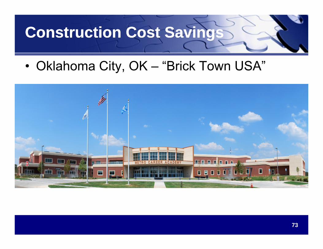
Construction Cost SavingsConstruction Cost Savings
• Oklahoma City, OK – “Brick Town USA”
74
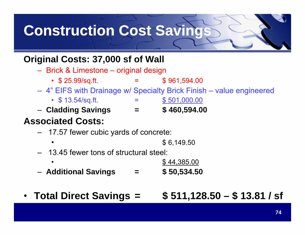
Construction Cost SavingsConstruction Cost Savings
Original Costs: 37,000 sf of Wall– Brick & Limestone – original design
• $ 25.99/sq.ft. = $ 961,594.00 – 4” EIFS with Drainage w/ Specialty Brick Finish – value engineered
• $ 13.54/sq.ft. = $ 501,000.00– Cladding Savings = $ 460,594.00
Associated Costs:– 17.57 fewer cubic yards of concrete:
• $ 6,149.50– 13.45 fewer tons of structural steel:
• $ 44,385.00– Additional Savings = $ 50,534.50
• Total Direct Savings = $ 511,128.50 – $ 13.81 / sf
75
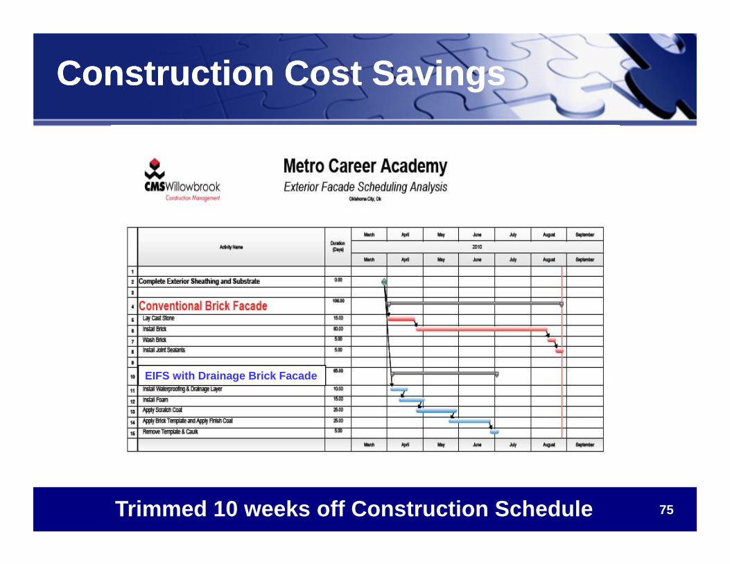
Construction Cost SavingsConstruction Cost Savings
Trimmed 10 weeks off Construction Schedule
EIFS with Drainage Brick Facade
76
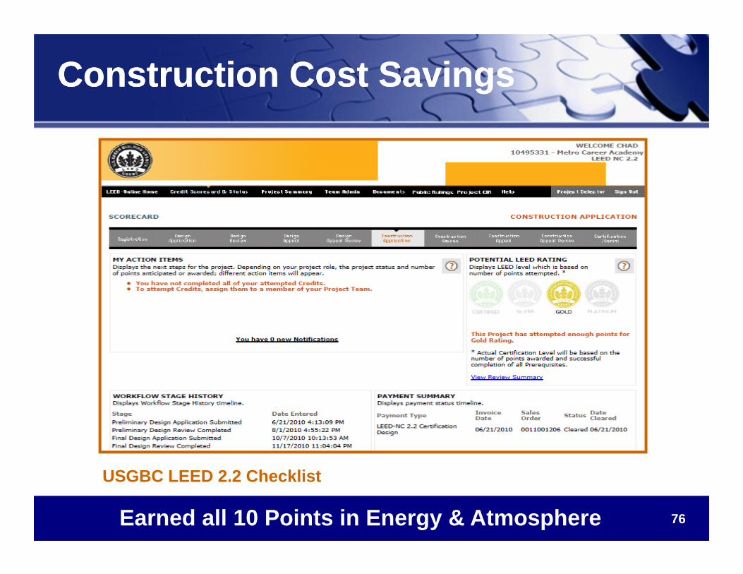
Construction Cost SavingsConstruction Cost Savings
USGBC LEED 2.2 Checklist
Earned all 10 Points in Energy & Atmosphere
77
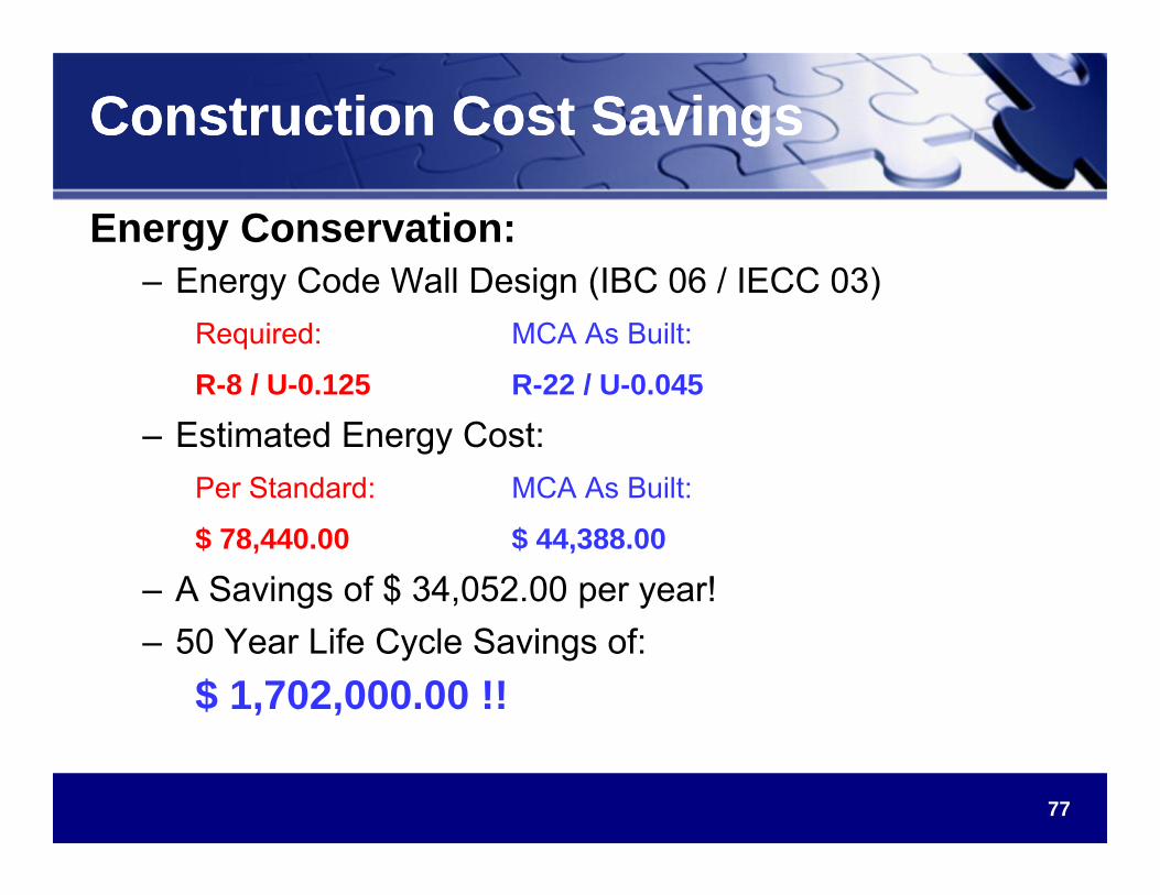
Construction Cost SavingsConstruction Cost Savings
Energy Conservation:– Energy Code Wall Design (IBC 06 / IECC 03)
Required: MCA As Built:
R-8 / U-0.125 R-22 / U-0.045
– Estimated Energy Cost:Per Standard: MCA As Built:
$ 78,440.00 $ 44,388.00
– A Savings of $ 34,052.00 per year!– 50 Year Life Cycle Savings of:
$ 1,702,000.00 !!
78
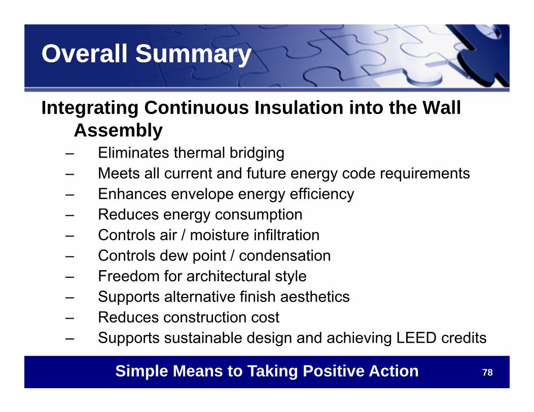
Overall SummaryOverall Summary
Integrating Continuous Insulation into the Wall Assembly
– Eliminates thermal bridging– Meets all current and future energy code requirements– Enhances envelope energy efficiency– Reduces energy consumption– Controls air / moisture infiltration– Controls dew point / condensation– Freedom for architectural style– Supports alternative finish aesthetics– Reduces construction cost– Supports sustainable design and achieving LEED credits
Simple Means to Taking Positive Action
79
This concludes the AIA / USGBCContinuing Education System Program
Questions?Thank you for your time!
www.dryvit.com • 800-556-7752